EP2303360B1 - Drug delivery pump drive using one or more shaped memory alloy wires - Google Patents
Drug delivery pump drive using one or more shaped memory alloy wiresDownload PDFInfo
- Publication number
- EP2303360B1 EP2303360B1EP09745518.2AEP09745518AEP2303360B1EP 2303360 B1EP2303360 B1EP 2303360B1EP 09745518 AEP09745518 AEP 09745518AEP 2303360 B1EP2303360 B1EP 2303360B1
- Authority
- EP
- European Patent Office
- Prior art keywords
- wheel
- memory alloy
- rotational direction
- shape memory
- pump drive
- Prior art date
- Legal status (The legal status is an assumption and is not a legal conclusion. Google has not performed a legal analysis and makes no representation as to the accuracy of the status listed.)
- Active
Links
Images


Classifications
- A—HUMAN NECESSITIES
- A61—MEDICAL OR VETERINARY SCIENCE; HYGIENE
- A61M—DEVICES FOR INTRODUCING MEDIA INTO, OR ONTO, THE BODY; DEVICES FOR TRANSDUCING BODY MEDIA OR FOR TAKING MEDIA FROM THE BODY; DEVICES FOR PRODUCING OR ENDING SLEEP OR STUPOR
- A61M5/00—Devices for bringing media into the body in a subcutaneous, intra-vascular or intramuscular way; Accessories therefor, e.g. filling or cleaning devices, arm-rests
- A61M5/14—Infusion devices, e.g. infusing by gravity; Blood infusion; Accessories therefor
- A61M5/142—Pressure infusion, e.g. using pumps
- A61M5/145—Pressure infusion, e.g. using pumps using pressurised reservoirs, e.g. pressurised by means of pistons
- A61M5/1452—Pressure infusion, e.g. using pumps using pressurised reservoirs, e.g. pressurised by means of pistons pressurised by means of pistons
- A—HUMAN NECESSITIES
- A61—MEDICAL OR VETERINARY SCIENCE; HYGIENE
- A61M—DEVICES FOR INTRODUCING MEDIA INTO, OR ONTO, THE BODY; DEVICES FOR TRANSDUCING BODY MEDIA OR FOR TAKING MEDIA FROM THE BODY; DEVICES FOR PRODUCING OR ENDING SLEEP OR STUPOR
- A61M5/00—Devices for bringing media into the body in a subcutaneous, intra-vascular or intramuscular way; Accessories therefor, e.g. filling or cleaning devices, arm-rests
- A61M5/14—Infusion devices, e.g. infusing by gravity; Blood infusion; Accessories therefor
- A61M5/142—Pressure infusion, e.g. using pumps
- A61M5/14244—Pressure infusion, e.g. using pumps adapted to be carried by the patient, e.g. portable on the body
- F—MECHANICAL ENGINEERING; LIGHTING; HEATING; WEAPONS; BLASTING
- F03—MACHINES OR ENGINES FOR LIQUIDS; WIND, SPRING, OR WEIGHT MOTORS; PRODUCING MECHANICAL POWER OR A REACTIVE PROPULSIVE THRUST, NOT OTHERWISE PROVIDED FOR
- F03G—SPRING, WEIGHT, INERTIA OR LIKE MOTORS; MECHANICAL-POWER PRODUCING DEVICES OR MECHANISMS, NOT OTHERWISE PROVIDED FOR OR USING ENERGY SOURCES NOT OTHERWISE PROVIDED FOR
- F03G7/00—Mechanical-power-producing mechanisms, not otherwise provided for or using energy sources not otherwise provided for
- F03G7/06—Mechanical-power-producing mechanisms, not otherwise provided for or using energy sources not otherwise provided for using expansion or contraction of bodies due to heating, cooling, moistening, drying or the like
- F03G7/061—Mechanical-power-producing mechanisms, not otherwise provided for or using energy sources not otherwise provided for using expansion or contraction of bodies due to heating, cooling, moistening, drying or the like characterised by the actuating element
- F03G7/0614—Mechanical-power-producing mechanisms, not otherwise provided for or using energy sources not otherwise provided for using expansion or contraction of bodies due to heating, cooling, moistening, drying or the like characterised by the actuating element using shape memory elements
- F03G7/06143—Wires
- F—MECHANICAL ENGINEERING; LIGHTING; HEATING; WEAPONS; BLASTING
- F03—MACHINES OR ENGINES FOR LIQUIDS; WIND, SPRING, OR WEIGHT MOTORS; PRODUCING MECHANICAL POWER OR A REACTIVE PROPULSIVE THRUST, NOT OTHERWISE PROVIDED FOR
- F03G—SPRING, WEIGHT, INERTIA OR LIKE MOTORS; MECHANICAL-POWER PRODUCING DEVICES OR MECHANISMS, NOT OTHERWISE PROVIDED FOR OR USING ENERGY SOURCES NOT OTHERWISE PROVIDED FOR
- F03G7/00—Mechanical-power-producing mechanisms, not otherwise provided for or using energy sources not otherwise provided for
- F03G7/06—Mechanical-power-producing mechanisms, not otherwise provided for or using energy sources not otherwise provided for using expansion or contraction of bodies due to heating, cooling, moistening, drying or the like
- F03G7/062—Mechanical-power-producing mechanisms, not otherwise provided for or using energy sources not otherwise provided for using expansion or contraction of bodies due to heating, cooling, moistening, drying or the like characterised by the activation arrangement
- F—MECHANICAL ENGINEERING; LIGHTING; HEATING; WEAPONS; BLASTING
- F03—MACHINES OR ENGINES FOR LIQUIDS; WIND, SPRING, OR WEIGHT MOTORS; PRODUCING MECHANICAL POWER OR A REACTIVE PROPULSIVE THRUST, NOT OTHERWISE PROVIDED FOR
- F03G—SPRING, WEIGHT, INERTIA OR LIKE MOTORS; MECHANICAL-POWER PRODUCING DEVICES OR MECHANISMS, NOT OTHERWISE PROVIDED FOR OR USING ENERGY SOURCES NOT OTHERWISE PROVIDED FOR
- F03G7/00—Mechanical-power-producing mechanisms, not otherwise provided for or using energy sources not otherwise provided for
- F03G7/06—Mechanical-power-producing mechanisms, not otherwise provided for or using energy sources not otherwise provided for using expansion or contraction of bodies due to heating, cooling, moistening, drying or the like
- F03G7/063—Mechanical-power-producing mechanisms, not otherwise provided for or using energy sources not otherwise provided for using expansion or contraction of bodies due to heating, cooling, moistening, drying or the like characterised by the mechanic interaction
- F03G7/0631—One-way operation, e.g. release mechanism
- F—MECHANICAL ENGINEERING; LIGHTING; HEATING; WEAPONS; BLASTING
- F03—MACHINES OR ENGINES FOR LIQUIDS; WIND, SPRING, OR WEIGHT MOTORS; PRODUCING MECHANICAL POWER OR A REACTIVE PROPULSIVE THRUST, NOT OTHERWISE PROVIDED FOR
- F03G—SPRING, WEIGHT, INERTIA OR LIKE MOTORS; MECHANICAL-POWER PRODUCING DEVICES OR MECHANISMS, NOT OTHERWISE PROVIDED FOR OR USING ENERGY SOURCES NOT OTHERWISE PROVIDED FOR
- F03G7/00—Mechanical-power-producing mechanisms, not otherwise provided for or using energy sources not otherwise provided for
- F03G7/06—Mechanical-power-producing mechanisms, not otherwise provided for or using energy sources not otherwise provided for using expansion or contraction of bodies due to heating, cooling, moistening, drying or the like
- F03G7/063—Mechanical-power-producing mechanisms, not otherwise provided for or using energy sources not otherwise provided for using expansion or contraction of bodies due to heating, cooling, moistening, drying or the like characterised by the mechanic interaction
- F03G7/0634—Mechanical-power-producing mechanisms, not otherwise provided for or using energy sources not otherwise provided for using expansion or contraction of bodies due to heating, cooling, moistening, drying or the like characterised by the mechanic interaction using cam gearings
- A—HUMAN NECESSITIES
- A61—MEDICAL OR VETERINARY SCIENCE; HYGIENE
- A61M—DEVICES FOR INTRODUCING MEDIA INTO, OR ONTO, THE BODY; DEVICES FOR TRANSDUCING BODY MEDIA OR FOR TAKING MEDIA FROM THE BODY; DEVICES FOR PRODUCING OR ENDING SLEEP OR STUPOR
- A61M2205/00—General characteristics of the apparatus
- A61M2205/02—General characteristics of the apparatus characterised by a particular materials
- A61M2205/0266—Shape memory materials
- Y—GENERAL TAGGING OF NEW TECHNOLOGICAL DEVELOPMENTS; GENERAL TAGGING OF CROSS-SECTIONAL TECHNOLOGIES SPANNING OVER SEVERAL SECTIONS OF THE IPC; TECHNICAL SUBJECTS COVERED BY FORMER USPC CROSS-REFERENCE ART COLLECTIONS [XRACs] AND DIGESTS
- Y10—TECHNICAL SUBJECTS COVERED BY FORMER USPC
- Y10T—TECHNICAL SUBJECTS COVERED BY FORMER US CLASSIFICATION
- Y10T74/00—Machine element or mechanism
- Y10T74/18—Mechanical movements
- Y10T74/18056—Rotary to or from reciprocating or oscillating
Definitions
- the present inventionis generally related drug delivery pumps, and in particular to a drug delivery pump drive using a shape memory alloy to advance a plunger piston to deliver a liquid drug from a container.
- miniature drug delivery pumpsuse an electric motor and a system of many gears to reduce the high speed motors down to a slower speed.
- the slower speedprovides the precision needed to control the very small doses of a liquid drug being delivered by means of an advancing lead screw and nut moving the syringe piston.
- Due to the above performance requirements, such miniature drug delivery pumpuse an expensive high quality electric motor and the associated high quality gears, therefore making such pumps expensive and generally not disposable in nature.
- concealment under clothingis problematic due the relative size of the motor and the noise generated during operation.
- WO 2004/056412shows a syringe-type infusion pump drive with a unidirectionally rotatable ratchet wheel with threads interacting with a threaded plunger rod to axially displace the plunger within the syringe container.
- One spring loaded pawlprevents the ratchet wheel from rotating in the wrong direction.
- a second spring loaded pawlis actuated in the drive direction by a contracting shape memory alloy (SMA) wire, rotating the ratchet wheel by one tooth.
- SMAcontracting shape memory alloy
- WO 03/048571 A1discloses a rotary or linear motor actuated by SMA wires. Instead of spring elements to restore the SMA wire after contraction, the small force due to the reverse shape memory effect is used to move the actuator in the direction opposite to contraction. For that purpose the SMA wire is placed in a low friction guide, where its motion during expansion is directed in one single direction.
- EP1130257 A2describes a rope made from SMA wires that is used to actuate a large scale ratchet mechanism.
- WO 2004/082108 A1discloses a discrete step rotary actuator comprising a stator, a rotor and actuating elements made with SMA wires, the actuating elements having a first portion anchored to the stator and a second portion with a terminal element.
- the rotorhas a number of circumferentially arranged seatings, into which the terminal elements can engage when the SMA wires are contracted.
- the passage of the SMA wires from the extended configuration to the shortened configurationimparts a ratchet like rotation couple on the rotor with respect to the stator.
- Spring elements placed between the actuating element and the statorinduce the displacement of the terminal element between two consecutive seatings during the passage of the SMA wires from the shortened to the extended configuration.
- US 2003/0229310 A1discloses a syringe-type infusion pump, in which a plunger comprising a SMA actuator is unilaterally displaced within a cylinder, in order to expel the liquid from the cylinder.
- the plungerconsists of an elongated two-way SMA element secured between a first and a second lateral segment of the plunger.
- the SMA elementWhen the SMA element is heated, the length of the element decreases and draws together the two lateral segments.
- the SMA elementWhen the SMA element is cooled down, it increases its length again and pushes apart the two lateral segments.
- the two lateral segmentsfrictionally engage with the cylinder wall and are shaped and sized such that they can move only in one direction.
- each cycle of heating and cooling the SMA elementunilaterally shifts the plunger by a certain distance in a caterpillar-like manner, thereby pushing the liquid out of the cylinder.
- US 2002/0005681 A1shows a motor driven by piezo elements coupled to a clutch and a counter mass.
- the high frequency oscillations of the piezo elementsare transferred via the roller clutch to a rotating shaft.
- the present inventionprovides a drug delivery pump drive which uses a shape memory alloy (SMA) to advance a plunger piston to deliver a liquid drug from a container and a method thereof.
- SMAshape memory alloy
- the small size of the SMA based pump drivehelps to reduce overall size of the drug delivery pump, thereby resulting in a suitable wearable device.
- the drug delivery pumpmay be disposable.
- the present inventionin one embodiment provides a SMA based pump drive for a miniature drug delivery pump having a single SMA wire used to drive a main wheel in a driven direction and a spring to rewind the main wheel after each drive cycle.
- the SMA based pump driveprovides a pair of SMA wires which are wrapped around the circumference of the main wheel in opposite directions and connected thereto so that one SMA wire rotates the main wheel clockwise and the other SMA wire rotates the wheel counter clockwise when excited sequentially.
- the SMA based pump driveprovides a plurality of the above mentioned opposed pairs of the SMA wires.
- a SMA wireis provided in a linear solenoid arrangement with a spring return to provide reciprocating linear motion.
- a set of concentric (inner and outer) tubes having matching facing helical slots with bearings therebetweenis provided to convert the reciprocating linear motion into reciprocating rotary motion.
- the SMA wire and spring returnlinearly reciprocate, pulling the inner tube therewith, the helical slots and bearings between the inner and outer tubes cause the outer tube to rotate a few degrees back and forth for each drive cycle.
- the outer tubebeing connected to the main wheel, transfers this clockwise and counterclockwise (reciprocating rotary) motion for each drive cycle to the main wheel.
- a unidirectional clutchwhich converts the reciprocating rotary motion of the main wheel into rotational motion in a single direction. This rotational motion in a single direction is used to advance a lead screw and push the plunger piston to dispense the liquid drug from the container.
- a pump drive used to dispense a liquid drug from a container having a plunger pistoncomprises a unidirectional clutch provided about a rotational axis and supporting centrally a wheel.
- the unidirectional clutchhas an inner race operably connected to the plunger piston, wherein the unidirectional clutch is configured to rotate both the inner race about the rotational axis in unison with rotation of the wheel in only a first rotational direction which advances the plunger piston, and to let the wheel rotate relative to the inner race about the rotational axis in a second rotational direction opposite to the first rotational direction without advancing the plunger piston.
- the pump drivealso includes at least one shape memory alloy wire providing a motor force when excited to rotate the wheel in at least the first rotational direction.
- a pump driveused to dispense a liquid drug from a container having a plunger piston.
- the pump drivecomprises a lead screw having a rotational axis and being operably connected to the plunger piston wherein rotation of the lead screw about the rotational axis advances the piston plunger in a dispensing direction which dispenses the liquid drug from the container, a wheel, and a unidirectional clutch provided about the rotational axis and supporting centrally the wheel.
- the unidirectional clutchhas an inner race connected centrally to the lead screw, wherein the unidirectional clutch is configured to rotate both the inner race and lead screw about the rotational axis in unison with rotation of the wheel in only a first rotational direction, and to let the wheel rotate relative to the inner race without rotating the lead screw about the rotational axis in a second rotational direction opposite to the first rotational direction.
- the pump drivefurther includes at least one shape memory alloy wire providing a motor force when excited to rotate the wheel in at least the first rotational direction.
- a pump drive used to dispense a liquid drug from a container having a plunger pistoncomprises a unidirectional clutch provided about a rotational axis and supporting centrally a wheel.
- the unidirectional clutchhas an inner race operably connected to the plunger piston, wherein the unidirectional clutch is configured to rotate both the inner race about the rotational axis in unison with rotation of the wheel in only a first rotational direction which advances the plunger piston, and to let the wheel rotate relative to the inner race about the rotational axis in a second rotational direction opposite to the first rotational direction without advancing the plunger piston.
- the pump drivealso includes a linear drive to rotate the wheel in the second rotational direction, and a pair of inner and outer concentric tubes with helical slots and bearings therebetween located about the axis of rotation.
- the linear driveacts on the inner tube in opposition such that the inner tube reciprocates with linear motion along the axis of rotation, wherein the helical slots and bearings cause the outer tube to reciprocate with rotary motion about the axis of rotation as the inner tube reciprocates with linear motion along the axis of rotation, and wherein the outer tube is connected to the wheel such that the rotary motion of the outer tube causes the wheel to rotate in the first rotational direction and then in the second rotational direction.
- a method of dispensing a liquid drug from a container having a plunger pistoncomprises providing a unidirectional clutch about a rotational axis which supports centrally a wheel, the unidirectional clutch having an inner race operably connected to the plunger piston, wherein the unidirectional clutch both rotates the inner race about the rotational axis in unison with rotation of the wheel in only a first rotational direction which advances the plunger piston, and lets the wheel rotate relative to the inner race about the rotational axis in a second rotational direction opposite to the first rotational direction without advancing the plunger piston.
- the methodalso includes providing a motor force by exciting at least one shape memory alloy wire which rotates the wheel in at least the first rotational direction.
- a method of dispensing a liquid drug from a container having a plunger pistoncomprises providing a unidirectional clutch about a rotational axis which supports centrally a wheel, the unidirectional clutch having an inner race operably connected to the plunger piston, wherein the unidirectional clutch both rotates the inner race about the rotational axis in unison with rotation of the wheel in only a first rotational direction which advances the plunger piston, and lets the wheel rotate relative to the inner race about the rotational axis in a second rotational direction opposite to the first rotational direction without advancing the plunger piston; providing a linear drive to rotate the wheel in the second rotational direction.
- the methodalso includes providing a pair of inner and outer concentric tubes with helical slots and bearings therebetween located about the axis of rotation, wherein the linear drive acts on the inner tube in opposition such that the inner tube reciprocates with linear motion along the axis of rotation, wherein the helical slots and bearings cause the outer tube to reciprocate with rotary motion about the axis of rotation as the inner tube reciprocates with linear motion along the axis of rotation, and wherein the outer tube is connected to the wheel such that the rotary motion of the outer tube causes the wheel to rotate in the first rotational direction and then in the second rotational direction.
- a method of dispensing a liquid drug from a container having a plunger pistoncomprises providing a lead screw having a rotational axis and operably connecting the lead screw to the plunger piston wherein rotation of the lead screw about the rotational axis advances the piston plunger in a dispensing direction which dispenses the liquid drug from the container, providing a wheel, and providing a unidirectional clutch to support the wheel about the rotational axis.
- the methodfurther includes connecting an inner race of the unidirectional clutch centrally to the lead screw, wherein the unidirectional clutch is configured to rotate both the inner race and lead screw about the rotational axis in unison with rotation of the wheel only in a first rotational direction, and to let the wheel rotation relative to the inner race without rotating the lead screw about the rotational axis in a second rotational direction opposite to the first rotational direction; providing at least one shape memory alloy wire which when excited provides a motor force to rotate the wheel in at least the first rotational direction; and exciting the shape memory alloy wire.
- the present inventionprovides a miniature drug delivery pump which uses a shape memory alloy (SMA) based pump drive to advance a syringe plunger to deliver a liquid drug from a container.
- SMAshape memory alloy
- the present inventionhas a cost and size advantage compared to traditional miniature drug delivery pumps and is a very compact and potentially disposable pump device design due to cost.
- FIGS. 1-4various illustrative embodiments of the SMA based pump drive according to the present invention are shown, and generally indicated by symbols 10, 20, 30, and 40, respectively. All of these embodiments of the SMA based pump drive 10, 20, 30, and 40 are reciprocating in design which converts linear motion of at least one SMA wire into unidirectional rotary motion.
- Shape memory alloysare metals which exhibit two very unique properties, pseudo-elasticity, and a shape memory effect due to the metals having Martensite (unheated, deformable state) and Austenite (heated, original shape recovering state) phase changes. In most shape memory alloys, a temperature change of only about 10°C is necessary to initiate the phase change (Martensite to Austenite) to recover an original size and shape of the wire after elongation and deformation.
- Alloys used as a shape memory alloy (SMA) wireinclude, for example and not limited thereto, copper based alloys, such as for example, copper-zinc-aluminum-nickel, copper-aluminum-nickel, iron- manganese-silicon alloys, and nickel-titanium (NiTi) alloys.
- the present inventionin all embodiments uses at least one SMA wire as a prime mover for a unidirectional clutch which turns in one direction a lead screw which translates a plunger piston to dispense a liquid, such as a drug, from a container or cartridge.
- a shape memory alloy (SMA) wire 12is fixed at one end 16 to a support 18.
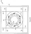
- the other end 22 of the SMA wire 12is wrapped around the circumference and connected to a main wheel 24 (i.e., an outer race) of a unidirectional clutch 28.
- Excitation (heating) of the SMA wire 12causes the SMA wire 12 to work to regain it original size and shape, i.e., shorten in length, which rotates the main wheel 24 in a first direction about an axis of rotation, indicated by symbol "X".
- a spring 26After excitation and cooling below the Martensite phase temperature, a spring 26 re-deforms by bending and elongating the SMA wire 12, and rotates the main wheel 24 in a second opposed direction about the axis of rotation X to complete a drive cycle. As shown, the spring 26 is also attached to the support 18 at one end and to the main wheel 24 at the other end at point which places the spring 26 in opposition to the contraction of the SMA wire 12 when in the Austenite phase.
- the excitation of the SMA wire 12is effected by the application of electrical energy from a battery 62 via conductors 14 which creates heat through the resistance of the SMA wire 12 itself.
- the application of the electrical energy from the battery 62is controlled by a controller 25 which is configured to switch the electrical energy on and off.
- the switchingis a timed pulse when command by a user to operate, such as for example, via a push button 72.
- pushing the push button 72results in the controller 25 switching the electrical energy from the battery 62 on and off such that the SMA wire 12 will complete the correct number of drive cycles to release a defined quantity of the liquid drug.
- a push of the push button 72causes the release of a dose of 0.5 ml of insulin.
- other dosages per push of the push button 72are also possible, which may range from 0.1 ml to 1 ml, and will depend on the programming/circuitry of controller 25, degrees of rotation of the main wheel 24 effected by the SMA wire 12, the transmitted torque of the unidirectional clutch 28 to a lead screw 32, and threading 41 between the lead screw 32 and a nut portion 43 of a plunger piston 44 ( FIG. 6 ), which advances a plunger piston 44 to dispense the liquid drug from a drug container 46 ( FIG. 5 )
- each SMA wire 12is orientated adjacent the axis of rotation X of the main wheel 24, and in one particular embodiment, substantially perpendicular to the axis of rotation X.
- each SMA wire 12is wrapped around at least half of the circumference of the main wheel 24 with the end 22 of the SMA wire 12 coupled directly thereto.
- each SMA wire 12extends about three quarters of the way around the circumference of the main wheel 24 and is coupled to a spoke 31 as best shown by FIG.
- the spoke 31is situated above a surface portion 33 of the main wheel 24 that is recessed below the outermost circumference of the main wheel 24 and extends in a direction parallel to the axis of rotation X.
- the outermost circumference of the main wheel 24is defined by front and rear face plate portions 35a and 35b, respectively.
- the spoke 31spans between and is mounted at respective ends to the front and rear face plate portions 35a and 35b.
- the SMA wire 12connects to the spoke 31 in a conventional fashion, such as for example, and not limited thereto, welding, screwing, wrapping, clamping, etc.
- an opposed pair of SMA wires 12a and 12bare connected at their first ends to a respective support 18. At their other ends, the SMA wires 12a and 12b are connected to the main wheel 24 in opposition, such that the excitation of one wire will deform the other and vice-versa, thereby causing cycling of the main wheel 24 in a clockwise and counter clockwise fashion.
- the SMA wires 12a and 12bare electrical energized and controlled as described above with reference to the conductors 14, the controller 25, and the battery 62 shown by FIG. 1 , for brevity and ease of illustration, no further discussion or showing thereof in FIG. 2 is provided.
- each of the SMA wires 12a and 12bis also wrapped at least half way around the main wheel 24 and connected thereto, such as via spokes 31 as shown in the embodiment depicted in FIG. 2A .
- the other end of each SMA wire 12a and 12bis connected to and about the frame 19 such that opposed pairs of the SMA wires 12a and 12b act in opposition to each other in the same manner as shown in FIG. 2 , e.g., providing clockwise rotation and then providing counterclockwise rotation, or vice versa.
- a counteracting spring 26such as shown by FIG. 1 , is provided either singularly or a plurality replacing one side of the SMA wires 12a or 12b about the frame 19 and main wheel 24, such that the SMA wires provide rotation in a first direction (e.g., clockwise) and the spring(s) 26 provides rotation in a second direction (e.g., counterclockwise).
- first directione.g., clockwise
- second directione.g., counterclockwise
- SMA wire 12may be used in the SMA based pump drive 30 than the single or double SMA wire embodiments shown by FIGS. 1 and 2 , and still produce a desired torque.
- the SMA based pump drive 30provides a more robust system than the single and double SMA wire embodiments shown by FIGS. 1 and 2 , due to the fact that should any of the SMA wires 12a or 12b encounter mechanical failure, the other remaining opposed pairs of SMA wires 12a and 12b will continue to provide sufficient torque to rotate the main wheel 24 under the provided load and generate the motor force needed to push a plunger piston of a liquid drug container.
- the SMA based pump drive 30may be useful in health situations in which redundancy and reliability of delivering a liquid drug is needed.
- the opposed pairs of plurality of SMA wires 12a and 12bare electrical energized and controlled as described above with reference to FIG .2 , and via a plurality of the respective conductors 14 tied in parallel to the controller 25 and the battery 62 shown by FIG. 1 , for brevity and ease of illustration, no further discussion or showing thereof in FIG. 3 is provided.
- the SMA wire 12is provided as a coil in a linear drive 109 and orientated along the axis of rotation X of the main wheel 24.
- the SMA wire 12is operably coupled to the main wheel 24 via a linear solenoid arrangement, indicated generally by symbol 110, which includes the linear drive 109.
- the linear drive 109 shown in the FIG. 4may be replaced with an electro-magnetic solenoid with a spring return, if faster fluid deliver is a desire.
- the linear drive 109includes an actuator body 112, which is shown with a portion of a side wall 114 removed to show the interior components thereof.
- the actuator body 112Housed within the actuator body 112 is the coiled SMA wire 12 and a plunge rod 116.
- the plunge rod 116is housed slidably within the actuator body 112 and fixed for linear (back and forth) motion by a rail portion 118 provided on the side wall 114 engaged with a slot 120 provided on the plunge rod 116.
- the rail portion 118may be provided on the plunge rod 116 and the slot 120 provided on the side wall 114, wherein this alternative arrangement is illustrated by the shown hidden lines within the actuator body 112.
- the linear drive 109 of the solenoid arrangement 110also include a spring return 122 to provide the reciprocating linear motion after excitation of the coiled SMA wire 12 as explained above in a previous section.
- the spring return 122is a spring housed also within the actuator body 112 in opposition to (i.e., biased against) the Austenite phase of the coiled SMA wire 12.
- a set of concentric inner and outer tubes 124 and 126, respectively,is also provided by the linear solenoid arrangement 110.
- An extension portion 128 of the plunge rod 116which extends outwardly and centrally from the actuator body 112 connects centrally along the axis of rotation X to the inner tube 124. In this manner, the reciprocating linear motion of the plunge rod 116, due to movement from excitation of the coiled SMA wire 12 and the opposite motion thereafter from the spring return 122, is transferred to the inner tube 124.
- the set of concentric inner and outer tubes 124 and 126are provided with matching facing helical slots 130 having bearings 132 therebetween, which convert the reciprocating linear motion of the inner tube 124 into reciprocating rotary motion of the outer tube 126.
- the bearings 132 between the inner and outer tubesroll in their respective helical slots 130 causing the outer tube 126 to rotate a few degrees back and forth for each drive (push-pull) cycle of the plunge rod 116.
- the outer tube 126being connected to the main wheel 24, transfers this clockwise and counterclockwise (rotational) motion for each drive cycle to the main wheel 24.
- the unidirectional clutch 28is a one-way roller clutch or Sprag clutch; however, the invention is not limited in this respect and may find application with other unidirectional clutches.
- the unidirectional clutch 28alternately slips in one direction and then grabs in the opposite direction for each drive cycle of the SMA wire 12.
- the lead screw 32which is connected centrally along the axis of rotation X to the clutch 28, also turns in the non-slip direction.
- clutch rollers 34jam between the main wheel 24 and the inner race 36, locking them together. This locking action allows the angular displacement of the main wheel 24 to be transmitted to the lead screw 32.
- springs 38 between the clutch rollers 34 and inner race 36are compressed, relieving the jam (i.e., releasing the locking action) to permit the clutch rollers 34 to slip.
- the clutch rollers 34 slipthe main wheel 24 rotates freely about the inner race 26 such that no counterclockwise angular displacement of the main wheel 24 is transmitted to the lead screw 32.
- the clutch 28transmits angular displacement of the main wheel 24 to the lead screw 32 only if the main wheel 24 and inner race 26 move in the clockwise direction when the clutch rollers 34 are wedged (jammed) between the surface of their respective tilted slope pockets 37 of the main wheel 24 and outer surface of the inner race 26.
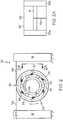
- FIG. 5an exploded view of an embodiment of a miniature drug delivery pump, generally indicated by symbol 50 is shown, for example, with the SMA based pump drive 40 shown by FIG. 4 .
- the unidirectional rotational motion of the lead screw 32also causes rotation about the nut portion 43 of the plunger 42 causing linear movement (translation) of the plunger 42 along the axis of rotation X in a dispensing direction. Translation of the plunger 42 in the dispensing direction advances the plunger piston 44 to dispense a liquid drug from the drug container 46.
- the drug container 46is accommodated in a cradle 48 of a base 51 of the drug delivery pump 50.
- the drug container 46is removable from the cradle 48 of the drug delivery pump 50, via removing a removable cap 52 from a cover 54 of the drug delivery pump 50 which permits removing and replacing the drug container 46 via an opening 56 defined in the cover 54.
- the opening 56 and/or the drug container 46may be keyed or provided in shape which ensures proper alignment of the plunger piston 44 with the plunger 42.
- the drug container 46is not removable as the drug delivery pump 50 in such an embodiment is intended to be disposable after fully dispensing the liquid drug from the drug container 46.
- the cover 54snaps onto the base 51 without requiring separate cover fasteners via projections 58 of a pliable material which extend from the base 51 and resiliently seat into notches 60 provided in the inside surface of the cover 54.
- separate cover fastenersmay be provided.
- the battery 62is also provided to power the SMA based pump drive 40 of the drug delivery pump 50.
- the battery 62 in the illustrated embodimentis a size AAAA, which is about 42.5 mm long and about 8.3 mm in diameter, weighing around 6.5 grams. Output of alkaline batteries in this size is 1.5 volts, 625 mA ⁇ h. Although elements in the figures may be exaggerated in portion to other components, it is to be appreciated that the approximate relative size between the drug delivery pump 50 and the battery 62 is intended to be shown in the embodiment illustrated by FIG. 5 .
- the drug delivery pump 50is not much larger than the AAAA battery 62, and is in one embodiment about 61 mm long, about 32 mm wide, and 15.5 mm in height, and weighs about one ounce, with the drug container 46 holding 2 ml of a liquid drug.
- Such dimensions of the drug delivery pump 50is about one fourth the size of existing conventional pumps.
- the small size and weight of the drug delivery pump 50makes it easier for the patient to hold the deliver pump in place, such via an adhesive on the skin and/or to conceal the deliver pump under clothing.
- the battery 62is held in a battery cradle 64 provided in the base 51 and contacts electrical terminal posts 66.
- the conductors 14 of the SMA based pump drive 40each connect between a respective one of the electrical terminal posts 66 and the controller 25.
- a hole 70is provided in the cover 54 such that the push button 72 may be depressed to energize the SMA wire 12 of the SMA based pump drive 40. It is to be appreciated that other electrical/IC components are provided, but are not shown for convenience of illustration as the actual control and electrical system of the drug pump is not the focus of the present invention.
- the lead screw 32which extends through and supports the main wheel 24 and the unidirectional clutch 28 about the axis of rotation X, is supported in turn by a base support 76 and the cradle 48.
- one or more of the projections 58may serve to support the SMA based pump drive 40 against rearward thrust, which may further be support in other directions (e.g., up, side-to-side) by other supports, such a strapping 77. In this manner, motion by the SMA base pump drive 40, which is counter to the thrust and torque provided by the lead screw 32 when rotated along the axis of rotation X, is minimized.
- the lead screw 32in one embodiment has a key portion 78 which fits into a slot 80 provided in the inner race 36, such that the lead screw 32 rotates only with the inner race 36.
- the lead screw 32is accommodated in a threaded cavity 82 of the nut portion 43 of the plunger 42.
- the SMA wire 12 of the pump driveis energized by depressing the push button 72 ( FIG. 7 )
- the lead screw 32rotates and advances out of the threaded cavity 82 along the rotational axis X causing movement of the plunger 42.
- the plunger 42advances the plunger piston 44 into the drug container 46 ( FIG. 5 ) to dispense a liquid drug therefrom.
- the lead screw 32provides the threaded cavity 82 in which a threaded outer diameter (not shown) of the plunger 42 is accommodated.
- the inner race 36 of the clutch 28provides the threaded cavity 82 which act directly on the threaded outer diameter of the plunger 42.
- the drug delivery pump 50provides a scaled window 92 through which a portion of the plunger piston 44 is visible and by which the patient in one embodiment uses to meter the delivery of a relatively large dose of the liquid drug.
- dispensing of very small amounts of the liquid drugcan be provided by controlling the pump drive with a timed switching circuit of the controller 25, wherein depressing push button 72 activates the timed switching circuit which energizes the pump drive for a predetermined period per button push.
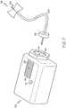
- the drug container 46includes an injection site 94 which is used to connect a spike connector 96 of an administration set 98 to the drug delivery pump 50.
- the spike connector 96is connected to a fluid conduit 100 which at the distal end connects to a catheter 102, which enters the patient's intravenous system through the skin for delivery of the liquid drug.
Landscapes
- Engineering & Computer Science (AREA)
- Chemical & Material Sciences (AREA)
- Combustion & Propulsion (AREA)
- Health & Medical Sciences (AREA)
- Mechanical Engineering (AREA)
- General Engineering & Computer Science (AREA)
- Biomedical Technology (AREA)
- Anesthesiology (AREA)
- Vascular Medicine (AREA)
- Heart & Thoracic Surgery (AREA)
- Hematology (AREA)
- Life Sciences & Earth Sciences (AREA)
- Animal Behavior & Ethology (AREA)
- General Health & Medical Sciences (AREA)
- Public Health (AREA)
- Veterinary Medicine (AREA)
- Infusion, Injection, And Reservoir Apparatuses (AREA)
- Reciprocating Pumps (AREA)
Description
- The present invention is generally related drug delivery pumps, and in particular to a drug delivery pump drive using a shape memory alloy to advance a plunger piston to deliver a liquid drug from a container.
- Typically miniature drug delivery pumps use an electric motor and a system of many gears to reduce the high speed motors down to a slower speed. The slower speed provides the precision needed to control the very small doses of a liquid drug being delivered by means of an advancing lead screw and nut moving the syringe piston. Due to the above performance requirements, such miniature drug delivery pump use an expensive high quality electric motor and the associated high quality gears, therefore making such pumps expensive and generally not disposable in nature. In addition, concealment under clothing is problematic due the relative size of the motor and the noise generated during operation.
WO 2004/056412 shows a syringe-type infusion pump drive with a unidirectionally rotatable ratchet wheel with threads interacting with a threaded plunger rod to axially displace the plunger within the syringe container. One spring loaded pawl prevents the ratchet wheel from rotating in the wrong direction. A second spring loaded pawl is actuated in the drive direction by a contracting shape memory alloy (SMA) wire, rotating the ratchet wheel by one tooth. The SMA wire is reset by a torque spring.WO 03/048571 A1 EP1130257 A2 describes a rope made from SMA wires that is used to actuate a large scale ratchet mechanism.WO 2004/082108 A1 discloses a discrete step rotary actuator comprising a stator, a rotor and actuating elements made with SMA wires, the actuating elements having a first portion anchored to the stator and a second portion with a terminal element. The rotor has a number of circumferentially arranged seatings, into which the terminal elements can engage when the SMA wires are contracted. The passage of the SMA wires from the extended configuration to the shortened configuration imparts a ratchet like rotation couple on the rotor with respect to the stator. Spring elements placed between the actuating element and the stator induce the displacement of the terminal element between two consecutive seatings during the passage of the SMA wires from the shortened to the extended configuration.US 2003/0229310 A1 discloses a syringe-type infusion pump, in which a plunger comprising a SMA actuator is unilaterally displaced within a cylinder, in order to expel the liquid from the cylinder. The plunger consists of an elongated two-way SMA element secured between a first and a second lateral segment of the plunger. When the SMA element is heated, the length of the element decreases and draws together the two lateral segments. When the SMA element is cooled down, it increases its length again and pushes apart the two lateral segments. The two lateral segments frictionally engage with the cylinder wall and are shaped and sized such that they can move only in one direction. As a result each cycle of heating and cooling the SMA element unilaterally shifts the plunger by a certain distance in a caterpillar-like manner, thereby pushing the liquid out of the cylinder.US 2002/0005681 A1 shows a motor driven by piezo elements coupled to a clutch and a counter mass. The high frequency oscillations of the piezo elements are transferred via the roller clutch to a rotating shaft.- It is against the above background that the present invention provides a drug delivery pump drive which uses a shape memory alloy (SMA) to advance a plunger piston to deliver a liquid drug from a container and a method thereof. The small size of the SMA based pump drive helps to reduce overall size of the drug delivery pump, thereby resulting in a suitable wearable device. In addition, due to the low cost of the SMA based pump drive, the drug delivery pump may be disposable.
- The present invention in one embodiment provides a SMA based pump drive for a miniature drug delivery pump having a single SMA wire used to drive a main wheel in a driven direction and a spring to rewind the main wheel after each drive cycle. In another embodiment, the SMA based pump drive provides a pair of SMA wires which are wrapped around the circumference of the main wheel in opposite directions and connected thereto so that one SMA wire rotates the main wheel clockwise and the other SMA wire rotates the wheel counter clockwise when excited sequentially. In another embodiment, the SMA based pump drive provides a plurality of the above mentioned opposed pairs of the SMA wires. In still another embodiment of the SMA based pump drive, a SMA wire is provided in a linear solenoid arrangement with a spring return to provide reciprocating linear motion. A set of concentric (inner and outer) tubes having matching facing helical slots with bearings therebetween is provided to convert the reciprocating linear motion into reciprocating rotary motion. As the SMA wire and spring return linearly reciprocate, pulling the inner tube therewith, the helical slots and bearings between the inner and outer tubes cause the outer tube to rotate a few degrees back and forth for each drive cycle. The outer tube being connected to the main wheel, transfers this clockwise and counterclockwise (reciprocating rotary) motion for each drive cycle to the main wheel. Inside the main wheel is a unidirectional clutch which converts the reciprocating rotary motion of the main wheel into rotational motion in a single direction. This rotational motion in a single direction is used to advance a lead screw and push the plunger piston to dispense the liquid drug from the container.
- In another embodiment, a pump drive used to dispense a liquid drug from a container having a plunger piston is disclosed. The pump drive comprises a unidirectional clutch provided about a rotational axis and supporting centrally a wheel. The unidirectional clutch has an inner race operably connected to the plunger piston, wherein the unidirectional clutch is configured to rotate both the inner race about the rotational axis in unison with rotation of the wheel in only a first rotational direction which advances the plunger piston, and to let the wheel rotate relative to the inner race about the rotational axis in a second rotational direction opposite to the first rotational direction without advancing the plunger piston. The pump drive also includes at least one shape memory alloy wire providing a motor force when excited to rotate the wheel in at least the first rotational direction.
- In still another embodiment, a pump drive used to dispense a liquid drug from a container having a plunger piston is disclosed. The pump drive comprises a lead screw having a rotational axis and being operably connected to the plunger piston wherein rotation of the lead screw about the rotational axis advances the piston plunger in a dispensing direction which dispenses the liquid drug from the container, a wheel, and a unidirectional clutch provided about the rotational axis and supporting centrally the wheel. The unidirectional clutch has an inner race connected centrally to the lead screw, wherein the unidirectional clutch is configured to rotate both the inner race and lead screw about the rotational axis in unison with rotation of the wheel in only a first rotational direction, and to let the wheel rotate relative to the inner race without rotating the lead screw about the rotational axis in a second rotational direction opposite to the first rotational direction. The pump drive further includes at least one shape memory alloy wire providing a motor force when excited to rotate the wheel in at least the first rotational direction.
- In another embodiment, a pump drive used to dispense a liquid drug from a container having a plunger piston is disclosed. The pump drive comprises a unidirectional clutch provided about a rotational axis and supporting centrally a wheel. The unidirectional clutch has an inner race operably connected to the plunger piston, wherein the unidirectional clutch is configured to rotate both the inner race about the rotational axis in unison with rotation of the wheel in only a first rotational direction which advances the plunger piston, and to let the wheel rotate relative to the inner race about the rotational axis in a second rotational direction opposite to the first rotational direction without advancing the plunger piston. The pump drive also includes a linear drive to rotate the wheel in the second rotational direction, and a pair of inner and outer concentric tubes with helical slots and bearings therebetween located about the axis of rotation. In this embodiment, the linear drive acts on the inner tube in opposition such that the inner tube reciprocates with linear motion along the axis of rotation, wherein the helical slots and bearings cause the outer tube to reciprocate with rotary motion about the axis of rotation as the inner tube reciprocates with linear motion along the axis of rotation, and wherein the outer tube is connected to the wheel such that the rotary motion of the outer tube causes the wheel to rotate in the first rotational direction and then in the second rotational direction.
- In another embodiment, a method of dispensing a liquid drug from a container having a plunger piston is disclosed. The method comprises providing a unidirectional clutch about a rotational axis which supports centrally a wheel, the unidirectional clutch having an inner race operably connected to the plunger piston, wherein the unidirectional clutch both rotates the inner race about the rotational axis in unison with rotation of the wheel in only a first rotational direction which advances the plunger piston, and lets the wheel rotate relative to the inner race about the rotational axis in a second rotational direction opposite to the first rotational direction without advancing the plunger piston. The method also includes providing a motor force by exciting at least one shape memory alloy wire which rotates the wheel in at least the first rotational direction.
- In still another embodiment, a method of dispensing a liquid drug from a container having a plunger piston is disclosed. The method comprises providing a unidirectional clutch about a rotational axis which supports centrally a wheel, the unidirectional clutch having an inner race operably connected to the plunger piston, wherein the unidirectional clutch both rotates the inner race about the rotational axis in unison with rotation of the wheel in only a first rotational direction which advances the plunger piston, and lets the wheel rotate relative to the inner race about the rotational axis in a second rotational direction opposite to the first rotational direction without advancing the plunger piston; providing a linear drive to rotate the wheel in the second rotational direction. The method also includes providing a pair of inner and outer concentric tubes with helical slots and bearings therebetween located about the axis of rotation, wherein the linear drive acts on the inner tube in opposition such that the inner tube reciprocates with linear motion along the axis of rotation, wherein the helical slots and bearings cause the outer tube to reciprocate with rotary motion about the axis of rotation as the inner tube reciprocates with linear motion along the axis of rotation, and wherein the outer tube is connected to the wheel such that the rotary motion of the outer tube causes the wheel to rotate in the first rotational direction and then in the second rotational direction.
- In yet another embodiment, a method of dispensing a liquid drug from a container having a plunger piston is disclosed. The method comprises providing a lead screw having a rotational axis and operably connecting the lead screw to the plunger piston wherein rotation of the lead screw about the rotational axis advances the piston plunger in a dispensing direction which dispenses the liquid drug from the container, providing a wheel, and providing a unidirectional clutch to support the wheel about the rotational axis. The method further includes connecting an inner race of the unidirectional clutch centrally to the lead screw, wherein the unidirectional clutch is configured to rotate both the inner race and lead screw about the rotational axis in unison with rotation of the wheel only in a first rotational direction, and to let the wheel rotation relative to the inner race without rotating the lead screw about the rotational axis in a second rotational direction opposite to the first rotational direction; providing at least one shape memory alloy wire which when excited provides a motor force to rotate the wheel in at least the first rotational direction; and exciting the shape memory alloy wire.
- These and other features and advantages of the invention will be more fully understood from the following description of various embodiments of the invention taken together with the accompanying drawings.
- The following detailed description of the various embodiments of the present invention can be best understood when read in conjunction with the following drawings, where like structure is indicated with like reference numerals and in which:
FIG. 1 is an end view of one embodiment of a SMA based pump drive according to the present invention having a single SMA wire with a spring return and a unidirectional clutch;FIG. 2 is an end view of another embodiment of a SMA based pump drive according to the present invention having an opposed pair of SMA wires and a unidirectional clutch;FIG. 2A is a section view of the embodiment shown byFIG. 2 and taken alongsection line 2A-2A;FIG. 3 is an end view of still another embodiment of a SMA based pump drive according to the present invention having a plurality of opposed pairs of SMA wires and a unidirectional clutch;FIG. 4 is an exploded view of yet another embodiment of a SMA based pump drive according to the present invention having a coiled SMA wire with a spring return driving a pair of concentric tubes and a unidirectional clutch;FIG. 5 is an exploded view of an embodiment of a miniature drug delivery pump according to the present invention and shown with the SMA based pump drive shown byFIG. 4 ;FIG. 6 is an exploded view of particular components of a SMA based pump drive and their arrangement thereof according to the present invention; andFIG. 7 is a perspective view of the miniature drug delivery pump embodiment shown byFIG. 5 according to the present invention with an administration set.- It is against the above background that the present invention provides a miniature drug delivery pump which uses a shape memory alloy (SMA) based pump drive to advance a syringe plunger to deliver a liquid drug from a container. The present invention has a cost and size advantage compared to traditional miniature drug delivery pumps and is a very compact and potentially disposable pump device design due to cost.
- In the following description of the embodiments of the invention, skilled artisans appreciate that elements in the figures are illustrated for simplicity and clarity and have not necessarily been drawn to scale. For example, the dimensions of some of the elements in the figures may be exaggerated relative to other elements to help to improve understanding of embodiment(s) of the present invention. Accordingly, the drawings are merely schematic representations, intending to depict only typical embodiments of the invention, and therefore should not be considered as limiting the scope of the invention. The invention will be described with additional specificity and detail through the accompanying drawings. The description of the invention may contain, for example, such descriptive terms as up, down, top, bottom, forward, back, clockwise, counterclockwise, right, or left. These terms are meant to provide a general orientation of the parts of the invention and are not meant to be limiting as to the scope of the invention.
- Referring now to
FIGS. 1-4 , various illustrative embodiments of the SMA based pump drive according to the present invention are shown, and generally indicated bysymbols pump drive - Shape memory alloys are metals which exhibit two very unique properties, pseudo-elasticity, and a shape memory effect due to the metals having Martensite (unheated, deformable state) and Austenite (heated, original shape recovering state) phase changes. In most shape memory alloys, a temperature change of only about 10°C is necessary to initiate the phase change (Martensite to Austenite) to recover an original size and shape of the wire after elongation and deformation. Alloys used as a shape memory alloy (SMA) wire include, for example and not limited thereto, copper based alloys, such as for example, copper-zinc-aluminum-nickel, copper-aluminum-nickel, iron- manganese-silicon alloys, and nickel-titanium (NiTi) alloys. The present invention in all embodiments uses at least one SMA wire as a prime mover for a unidirectional clutch which turns in one direction a lead screw which translates a plunger piston to dispense a liquid, such as a drug, from a container or cartridge.
- In the first illustrated embodiment of the SMA based pump drive10 shown by
FIG. 1 , a shape memory alloy (SMA)wire 12 is fixed at oneend 16 to asupport 18. Theother end 22 of theSMA wire 12 is wrapped around the circumference and connected to a main wheel24 (i.e., an outer race) of aunidirectional clutch 28. Excitation (heating) of theSMA wire 12 causes theSMA wire 12 to work to regain it original size and shape, i.e., shorten in length, which rotates themain wheel 24 in a first direction about an axis of rotation, indicated by symbol "X". After excitation and cooling below the Martensite phase temperature, aspring 26 re-deforms by bending and elongating theSMA wire 12, and rotates themain wheel 24 in a second opposed direction about the axis of rotation X to complete a drive cycle. As shown, thespring 26 is also attached to thesupport 18 at one end and to themain wheel 24 at the other end at point which places thespring 26 in opposition to the contraction of theSMA wire 12 when in the Austenite phase. - In the SMA based pump drive10 shown by
FIG. 1 , as with the other embodiments of the SMA basedpump drive 20, 30, and40 (FIGS. 2 ,3 , and4 , respectively), the excitation of theSMA wire 12 is effected by the application of electrical energy from abattery 62 viaconductors 14 which creates heat through the resistance of theSMA wire 12 itself. The application of the electrical energy from thebattery 62 is controlled by acontroller 25 which is configured to switch the electrical energy on and off. In one embodiment, the switching is a timed pulse when command by a user to operate, such as for example, via apush button 72. In one embodiment, pushing thepush button 72 results in thecontroller 25 switching the electrical energy from thebattery 62 on and off such that theSMA wire 12 will complete the correct number of drive cycles to release a defined quantity of the liquid drug. For example, in one embodiment, a push of thepush button 72 causes the release of a dose of 0.5 ml of insulin. In other embodiments, other dosages per push of thepush button 72 are also possible, which may range from 0.1 ml to 1 ml, and will depend on the programming/circuitry ofcontroller 25, degrees of rotation of themain wheel 24 effected by theSMA wire 12, the transmitted torque of the unidirectional clutch28 to alead screw 32, and threading41 between thelead screw 32 and anut portion 43 of a plunger piston44 (FIG. 6 ), which advances aplunger piston 44 to dispense the liquid drug from a drug container46 (FIG. 5 ) - It is to be appreciated that in the SMA based pump drives10, 20, and30 (
FIGS. 1-3 , respectively), eachSMA wire 12 is orientated adjacent the axis of rotation X of themain wheel 24, and in one particular embodiment, substantially perpendicular to the axis of rotation X. In addition, in the embodiments shown byFIGS. 1-3 , eachSMA wire 12 is wrapped around at least half of the circumference of themain wheel 24 with theend 22 of theSMA wire 12 coupled directly thereto. For example, in the illustrated embodiments shown inFIGS. 2 and3 , eachSMA wire 12 extends about three quarters of the way around the circumference of themain wheel 24 and is coupled to aspoke 31 as best shown byFIG. 2A , which is a side portion view of themain wheel 24 taken alongsection line 2A-2A inFIG. 2 . In one embodiment, thespoke 31 is situated above asurface portion 33 of themain wheel 24 that is recessed below the outermost circumference of themain wheel 24 and extends in a direction parallel to the axis of rotation X. In one embodiment the outermost circumference of themain wheel 24 is defined by front and rearface plate portions FIG. 2A , thespoke 31 spans between and is mounted at respective ends to the front and rearface plate portions SMA wire 12 connects to thespoke 31 in a conventional fashion, such as for example, and not limited thereto, welding, screwing, wrapping, clamping, etc. - As shown by
FIG. 2 , for this embodiment of the SMA based pump drive20, an opposed pair ofSMA wires respective support 18. At their other ends, theSMA wires main wheel 24 in opposition, such that the excitation of one wire will deform the other and vice-versa, thereby causing cycling of themain wheel 24 in a clockwise and counter clockwise fashion. As theSMA wires conductors 14, thecontroller 25, and thebattery 62 shown byFIG. 1 , for brevity and ease of illustration, no further discussion or showing thereof inFIG. 2 is provided. - With reference now to
FIG. 3 , for this SMA basedpump drive 30, a plurality of opposed pairs ofSMA wires frame 19 and the circumference of themain wheel 24. In this illustrated embodiment, each of theSMA wires main wheel 24 and connected thereto, such as viaspokes 31 as shown in the embodiment depicted inFIG. 2A . The other end of eachSMA wire frame 19 such that opposed pairs of theSMA wires FIG. 2 , e.g., providing clockwise rotation and then providing counterclockwise rotation, or vice versa. In an alternative embodiment, a counteractingspring 26, such as shown byFIG. 1 , is provided either singularly or a plurality replacing one side of theSMA wires frame 19 andmain wheel 24, such that the SMA wires provide rotation in a first direction (e.g., clockwise) and the spring(s)26 provides rotation in a second direction (e.g., counterclockwise). It is to be appreciated that in comparison to the SMA based pump drives10 and20 (FIGS. 1 and2 , respectively), if similar sized SMA wires are used, the SMA based pump drive30 ofFIG. 3 would provide a larger torque due to the greater number of similarlysized SMA wires 12. Accordingly, thinner, lowercost SMA wire 12 may be used in the SMA based pump drive30 than the single or double SMA wire embodiments shown byFIGS. 1 and2 , and still produce a desired torque. In addition, the SMA based pump drive30 provides a more robust system than the single and double SMA wire embodiments shown byFIGS. 1 and2 , due to the fact that should any of theSMA wires SMA wires main wheel 24 under the provided load and generate the motor force needed to push a plunger piston of a liquid drug container. Accordingly, the SMA based pump drive30 may be useful in health situations in which redundancy and reliability of delivering a liquid drug is needed. As the opposed pairs of plurality ofSMA wires FIG .2 , and via a plurality of therespective conductors 14 tied in parallel to thecontroller 25 and thebattery 62 shown byFIG. 1 , for brevity and ease of illustration, no further discussion or showing thereof inFIG. 3 is provided. - For the SMA based pump drive40 illustrated by
FIG. 4 , theSMA wire 12 is provided as a coil in alinear drive 109 and orientated along the axis of rotation X of themain wheel 24. TheSMA wire 12 is operably coupled to themain wheel 24 via a linear solenoid arrangement, indicated generally bysymbol 110, which includes thelinear drive 109. In an alternative embodiment, thelinear drive 109 shown in theFIG. 4 may be replaced with an electro-magnetic solenoid with a spring return, if faster fluid deliver is a desire. - In the illustrated embodiment, the
linear drive 109 includes anactuator body 112, which is shown with a portion of aside wall 114 removed to show the interior components thereof. Housed within theactuator body 112 is the coiledSMA wire 12 and aplunge rod 116. Theplunge rod 116 is housed slidably within theactuator body 112 and fixed for linear (back and forth) motion by arail portion 118 provided on theside wall 114 engaged with aslot 120 provided on theplunge rod 116. Alternatively, therail portion 118 may be provided on theplunge rod 116 and theslot 120 provided on theside wall 114, wherein this alternative arrangement is illustrated by the shown hidden lines within theactuator body 112. - The
linear drive 109 of thesolenoid arrangement 110 also include aspring return 122 to provide the reciprocating linear motion after excitation of the coiledSMA wire 12 as explained above in a previous section. In the illustrated embodiment, thespring return 122 is a spring housed also within theactuator body 112 in opposition to (i.e., biased against) the Austenite phase of the coiledSMA wire 12. A set of concentric inner andouter tubes linear solenoid arrangement 110. Anextension portion 128 of theplunge rod 116, which extends outwardly and centrally from theactuator body 112 connects centrally along the axis of rotation X to theinner tube 124. In this manner, the reciprocating linear motion of theplunge rod 116, due to movement from excitation of the coiledSMA wire 12 and the opposite motion thereafter from thespring return 122, is transferred to theinner tube 124. - The set of concentric inner and
outer tubes helical slots 130 havingbearings 132 therebetween, which convert the reciprocating linear motion of theinner tube 124 into reciprocating rotary motion of theouter tube 126. As theplunge rod 116 linearly reciprocates, pulling theinner tube 124 therewith, thebearings 132 between the inner and outer tubes roll in their respectivehelical slots 130 causing theouter tube 126 to rotate a few degrees back and forth for each drive (push-pull) cycle of theplunge rod 116. Theouter tube 126 being connected to themain wheel 24, transfers this clockwise and counterclockwise (rotational) motion for each drive cycle to themain wheel 24. - In one embodiment, the
unidirectional clutch 28 is a one-way roller clutch or Sprag clutch; however, the invention is not limited in this respect and may find application with other unidirectional clutches. In such an embodiment, as the back and forth oscillation of themain wheel 24 occurs, the unidirectional clutch28 alternately slips in one direction and then grabs in the opposite direction for each drive cycle of theSMA wire 12. As the unidirectional clutch28 turns in the non-slip direction, thelead screw 32, which is connected centrally along the axis of rotation X to the clutch28, also turns in the non-slip direction. - For example and with reference to
FIG. 1 , as themain wheel 24 rotates in the clockwise direction,clutch rollers 34 jam between themain wheel 24 and theinner race 36, locking them together. This locking action allows the angular displacement of themain wheel 24 to be transmitted to thelead screw 32. As themain wheel 24 rotates in an opposite (counterclockwise) direction, springs38 between theclutch rollers 34 andinner race 36 are compressed, relieving the jam (i.e., releasing the locking action) to permit theclutch rollers 34 to slip. As theclutch rollers 34 slip, themain wheel 24 rotates freely about theinner race 26 such that no counterclockwise angular displacement of themain wheel 24 is transmitted to thelead screw 32. Thus, in this embodiment, the clutch28 transmits angular displacement of themain wheel 24 to thelead screw 32 only if themain wheel 24 andinner race 26 move in the clockwise direction when theclutch rollers 34 are wedged (jammed) between the surface of their respective tilted slope pockets37 of themain wheel 24 and outer surface of theinner race 26. - With reference to
FIG. 5 , an exploded view of an embodiment of a miniature drug delivery pump, generally indicated bysymbol 50 is shown, for example, with the SMA based pump drive40 shown byFIG. 4 . In all embodiments, the unidirectional rotational motion of thelead screw 32 also causes rotation about thenut portion 43 of theplunger 42 causing linear movement (translation) of theplunger 42 along the axis of rotation X in a dispensing direction. Translation of theplunger 42 in the dispensing direction advances theplunger piston 44 to dispense a liquid drug from thedrug container 46. - As shown, the
drug container 46 is accommodated in acradle 48 of abase 51 of thedrug delivery pump 50. In one embodiment, thedrug container 46 is removable from thecradle 48 of thedrug delivery pump 50, via removing aremovable cap 52 from acover 54 of thedrug delivery pump 50 which permits removing and replacing thedrug container 46 via anopening 56 defined in thecover 54. In such an embodiment, theopening 56 and/or thedrug container 46 may be keyed or provided in shape which ensures proper alignment of theplunger piston 44 with theplunger 42. In another embodiment, thedrug container 46 is not removable as thedrug delivery pump 50 in such an embodiment is intended to be disposable after fully dispensing the liquid drug from thedrug container 46. - In the illustrated embodiment of
FIG. 5 , thecover 54 snaps onto thebase 51 without requiring separate cover fasteners viaprojections 58 of a pliable material which extend from thebase 51 and resiliently seat intonotches 60 provided in the inside surface of thecover 54. In an alternative embodiment separate cover fasteners may be provided. - The
battery 62 is also provided to power the SMA based pump drive40 of thedrug delivery pump 50. Thebattery 62 in the illustrated embodiment is a size AAAA, which is about 42.5 mm long and about 8.3 mm in diameter, weighing around 6.5 grams. Output of alkaline batteries in this size is 1.5 volts, 625 mA·h. Although elements in the figures may be exaggerated in portion to other components, it is to be appreciated that the approximate relative size between thedrug delivery pump 50 and thebattery 62 is intended to be shown in the embodiment illustrated byFIG. 5 . Accordingly, as shown thedrug delivery pump 50 is not much larger than theAAAA battery 62, and is in one embodiment about 61 mm long, about 32 mm wide, and 15.5 mm in height, and weighs about one ounce, with thedrug container 46 holding 2 ml of a liquid drug. Such dimensions of thedrug delivery pump 50 is about one fourth the size of existing conventional pumps. The small size and weight of thedrug delivery pump 50 makes it easier for the patient to hold the deliver pump in place, such via an adhesive on the skin and/or to conceal the deliver pump under clothing. - The
battery 62 is held in abattery cradle 64 provided in thebase 51 and contacts electrical terminal posts66. Theconductors 14 of the SMA based pump drive40 each connect between a respective one of the electrical terminal posts66 and thecontroller 25. A hole70 is provided in thecover 54 such that thepush button 72 may be depressed to energize theSMA wire 12 of the SMA basedpump drive 40. It is to be appreciated that other electrical/IC components are provided, but are not shown for convenience of illustration as the actual control and electrical system of the drug pump is not the focus of the present invention. - The
lead screw 32 which extends through and supports themain wheel 24 and the unidirectional clutch28 about the axis of rotation X, is supported in turn by a base support76 and thecradle 48. In addition, one or more of theprojections 58 may serve to support the SMA based pump drive40 against rearward thrust, which may further be support in other directions (e.g., up, side-to-side) by other supports, such a strapping77. In this manner, motion by the SMAbase pump drive 40, which is counter to the thrust and torque provided by thelead screw 32 when rotated along the axis of rotation X, is minimized. - With reference to
FIG. 6 , an exploded view of particular components of a SMA based pump drive and their arrangement thereof according to an embodiment of the present invention is shown. Thelead screw 32 in one embodiment has akey portion 78 which fits into a slot80 provided in theinner race 36, such that thelead screw 32 rotates only with theinner race 36. Thelead screw 32 is accommodated in a threadedcavity 82 of thenut portion 43 of theplunger 42. As theSMA wire 12 of the pump drive is energized by depressing the push button72 (FIG. 7 ), thelead screw 32 rotates and advances out of the threadedcavity 82 along the rotational axis X causing movement of theplunger 42. As the mentioned above previously, movement of the plunger42 (i.e., translational along the rotational axis X) advances theplunger piston 44 into the drug container46 (FIG. 5 ) to dispense a liquid drug therefrom. It is to be appreciated that in an alternative embodiment, the arrangement of thelead screw 32 and theplunger 42 used to push theplunger piston 44 is reversed. In such an alternative embodiment, thelead screw 32 provides the threadedcavity 82 in which a threaded outer diameter (not shown) of theplunger 42 is accommodated. In still another embodiment, theinner race 36 of the clutch28 provides the threadedcavity 82 which act directly on the threaded outer diameter of theplunger 42. - As shown by
FIG. 7 , in one embodiment, thedrug delivery pump 50 provides a scaledwindow 92 through which a portion of theplunger piston 44 is visible and by which the patient in one embodiment uses to meter the delivery of a relatively large dose of the liquid drug. In another embodiment, dispensing of very small amounts of the liquid drug can be provided by controlling the pump drive with a timed switching circuit of thecontroller 25, whereindepressing push button 72 activates the timed switching circuit which energizes the pump drive for a predetermined period per button push. Thedrug container 46 includes aninjection site 94 which is used to connect aspike connector 96 of an administration set98 to thedrug delivery pump 50. Thespike connector 96 is connected to afluid conduit 100 which at the distal end connects to acatheter 102, which enters the patient's intravenous system through the skin for delivery of the liquid drug. - Although not limited to, some of the noted advantages of the present invention are as follows: the inherent precision of the motion from the SMA wire which can be used to accurately deliver very small doses (i.e., about 0.01 ml), the ability to run at high frequency (up to 1 hz) to deliver quickly a large dose (i.e., about 1.0 ml), nearly silent operation, fewer moving parts, and inexpensive parts. Such advantages result in an overall compact and low cost drug delivery pump for the consumer.
- The foregoing description of the invention has been presented for purposes of illustration and description. It is not intended to be exhaustive or to limit the invention to the precise form disclosed, and other modifications and variations may be possible in light of the above teachings. The above embodiments disclosed were chosen and described to explain the principles of the invention and its practical application to thereby enable others skilled in the art to best utilize the invention. It is intended that the appended claims be construed to include other alternative embodiments of the invention except insofar as limited by the prior art.
Claims (16)
- A pump drive (10, 20, 30, 40) used to dispense a liquid drug from a container (46) having a plunger piston (44), said pump drivecharacterized by:a unidirectional clutch (28) provided about a rotational axis (X) and supporting centrally a wheel (24), the unidirectional clutch having an inner race (36) operably connected to the plunger piston, wherein the unidirectional clutch is configured to rotate both the inner race about the rotational axis in unison with rotation of the wheel in only a first rotational direction which advances the plunger piston, and to let the wheel rotate relative to the inner race about the rotational axis in a second rotational direction opposite to the first rotational direction without advancing the plunger piston; andat least one shape memory alloy wire (12, 12a, 12b) providing a motor force when excited to rotate the wheel in at least the first rotational direction.
- The pump drive according to claim 1,characterized by a lead screw (32) having a rotational axis (X) and being operably connected to the plunger piston (44), wherein rotation of the lead screw about the rotational axis (X) advances the piston plunger in a dispensing direction which dispenses the liquid drug from the container (46).
- The pump drive according to claim 1 or 2, further comprising a spring (26) to rotate the wheel (24) in the second rotational direction.
- The pump drive according to claim 1 or 2, further comprising a spring (26) connected directly to the wheel (24) to rotate the wheel in the second rotational direction, wherein the shape memory alloy wire (12, 12a, 12b) is also connected directly to the wheel.
- The pump drive according to claim 1 or 2, further comprising a spring (122) to rotate the wheel (24) in the second rotational direction, a pair of inner and outer concentric tubes (124, 126) with helical slots (130) and bearings (132) therebetween located about the axis of rotation (X), wherein the shaped memory alloy wire (12) and the spring act on the inner tube (124) in opposition such that the inner tube reciprocates with linear motion along the axis of rotation, wherein the helical slots and bearings cause the outer tube (126) to reciprocate with rotary motion about the axis of rotation as the inner tube reciprocates with linear motion along the axis of rotation, and wherein the outer tube is connected to the wheel such that the rotary motion of the outer tube causes the wheel to rotate in the first rotational direction and then in the second rotational direction.
- The pump drive according to claim 1 or 2, further comprising a spring (122) to rotate the wheel (24) in the second rotational direction, a pair of inner and outer concentric tubes (124, 126) with helical slots (130) and bearings (132) therebetween located about the axis of rotation (X), wherein the shaped memory alloy wire (12) and the spring are provided in an actuator body (112) and act on a plunge rod (116) in opposition such that the plunge rod reciprocates with linear motion along the axis of rotation, wherein the plunger rod is slidably housed in the actuator body and has a portion (128) that extends from the actuator body which connects to the inner tube, wherein the inner tube (124) reciprocates with linear motion along the axis of rotation with the plunge rod, wherein the helical slots and bearings cause the outer tube (126) to reciprocate with rotary motion about the axis of rotation as the inner tube reciprocates with linear motion along the axis of rotation, and wherein the outer tube is connected to the wheel such that the rotary motion of the outer tube causes the wheel to rotate in the first rotational direction and then in the second rotational direction.
- The pump drive according to claim 1 or 2, wherein the at least one shape memory alloy wire is a first shape memory alloy wire or a plurality of first shape memory alloy wires (12a) providing the motor force when excited to rotate the wheel (24) in the first rotational direction and a second shape memory alloy wire or a plurality of second shape memory alloy wires (12b) providing the motor force when excited to rotate the wheel in the second rotational direction.
- The pump drive according to claim 1 or 2, wherein the at least one shape memory alloy wire is a first shape memory wire or a plurality of first shape memory alloy wires (12a), each mounted directly and laterally to the wheel (24) and providing the motor force when excited to rotate the wheel in the first rotational direction, and a second shape memory alloy wire or a plurality of second shape memory alloy wires (12b), also mounted directly and laterally to the wheel and providing the motor force when excited to rotate the wheel in the second rotational direction.
- The pump drive according to claim 1 or 2, wherein the at least one shape memory alloy wire is a first shape memory wire or a plurality of first shape memory alloy wires (12a) mounted directly to a first spoke of the wheel (24) and providing the motor force when excited to rotate the wheel (24) in the first rotational direction, and a second shape memory alloy wire or a plurality of second shape memory alloy wires (12b) mounted directly to a second spoke (31) of the wheel and providing the motor force when excited to rotate the wheel in the second rotational direction, wherein the first and second spokes extend parallel to the axis of rotation (X).
- The pump drive according to claim 1 or 2, wherein the at least one shaped memory alloy wire is a plurality of shape memory alloy wires (12a), each mounted directly and laterally to the wheel (24) and providing the motor force when excited to rotate the wheel in the first rotational direction, and wherein the pump drive (10, 20, 30, 40) further comprises at least one spring (26) mounted directly and laterally to the wheel and acting in opposition to the plurality of shape memory alloy wires (38) to provide the motor force to rotate the wheel in the second rotational direction.
- The pump drive according to any of the preceding claims, wherein the shape memory alloy wire (12, 12a, 12b) is excited by applying and removing electric energy to the shape memory alloy wire.
- The pump drive according to any of the preceding claims, wherein the shape memory alloy wire (12, 12a, 12b) is formed from a material selected from copper based alloys, copper-zinc-aluminum-nickel, copper-aluminum-nickel, iron- manganese-silicon alloys, and nickel-titanium alloys.
- The pump drive according to claim 1, 2, 7, 8, or 9, wherein the shape memory alloy wire (12, 12a, 12b) is wrapped around at least half the circumference of the wheel (24).
- The pump drive according to claim 1, 2, 5, or 6,, wherein the shaped memory alloy wire (12, 12a, 12b) is formed as a coil.
- The pump drive according to claim 1 or 2, comprising: a linear drive (109) to rotate the wheel (24) in the second rotational direction, comprising a shaped memory alloy wire (12) and a return spring (122); and a pair of inner and outer concentric tubes (124, 126) with helical slots (130) and bearings (132) therebetween located about the axis of rotation (X), wherein the shaped memory alloy wire (12) and the return spring (122) of the linear drive act on the inner tube in opposition such that the inner tube reciprocates with linear motion along the axis of rotation, wherein the helical slots and bearings cause the outer tube to reciprocate with rotary motion about the axis of rotation as the inner tube reciprocates with linear motion along the axis of rotation, and wherein the outer tube is connected to the wheel such that the rotary motion of the outer tube causes the wheel to rotate in the first rotational direction and then in the second rotational direction.
- A drug delivery pump (50)characterized by a pump drive (10, 20, 30, 40) according to any of the preceding claims, and a container (46) holding the liquid drug.
Applications Claiming Priority (2)
| Application Number | Priority Date | Filing Date | Title |
|---|---|---|---|
| US12/120,672US8172811B2 (en) | 2008-05-15 | 2008-05-15 | Drug delivery pump drive using a shaped memory alloy wire |
| PCT/EP2009/003234WO2009138184A1 (en) | 2008-05-15 | 2009-05-06 | Drug delivery pump drive using one or more shaped memory alloy wires |
Publications (2)
| Publication Number | Publication Date |
|---|---|
| EP2303360A1 EP2303360A1 (en) | 2011-04-06 |
| EP2303360B1true EP2303360B1 (en) | 2017-01-18 |
Family
ID=41315097
Family Applications (1)
| Application Number | Title | Priority Date | Filing Date |
|---|---|---|---|
| EP09745518.2AActiveEP2303360B1 (en) | 2008-05-15 | 2009-05-06 | Drug delivery pump drive using one or more shaped memory alloy wires |
Country Status (4)
| Country | Link |
|---|---|
| US (3) | US8172811B2 (en) |
| EP (1) | EP2303360B1 (en) |
| DK (1) | DK2303360T3 (en) |
| WO (1) | WO2009138184A1 (en) |
Families Citing this family (17)
| Publication number | Priority date | Publication date | Assignee | Title |
|---|---|---|---|---|
| US8662443B2 (en) | 2011-02-02 | 2014-03-04 | The Boeing Company | Shape memory alloy actuated torsion lock |
| US8499913B2 (en)* | 2011-05-20 | 2013-08-06 | The Boeing Company | Shape memory alloy actuator system and method |
| EP2587057B1 (en)* | 2011-10-28 | 2016-04-13 | Arquimea Ingenieria, S.L. | Linear actuator device |
| US8904781B2 (en)* | 2012-07-13 | 2014-12-09 | Simmonds Precision Products, Inc. | Interlaced actuation system |
| USD741688S1 (en)* | 2013-01-23 | 2015-10-27 | Water Renu Llc | Bracket with slotted side walls |
| US9631268B2 (en) | 2013-02-26 | 2017-04-25 | The Boeing Company | Methods and systems for shape memory alloy structures |
| US20170290975A1 (en)* | 2016-04-06 | 2017-10-12 | Flextronics Ap, Llc | Automatic injection device having a drive system with a shape memory spring |
| US10274017B2 (en)* | 2016-10-21 | 2019-04-30 | General Electric Company | Method and system for elastic bearing support |
| GB201702038D0 (en)* | 2017-02-08 | 2017-03-22 | Cambridge Mechatronics Ltd | SMA dose verification |
| US10371132B2 (en) | 2017-02-10 | 2019-08-06 | Peopleflo Manufacturing, Inc. | Reciprocating pump and transmission assembly having a one-way clutch |
| WO2019052110A1 (en)* | 2017-09-12 | 2019-03-21 | 美敦力公司 | Fluid infusion device and driving mechanism therefor |
| CN107469186B (en)* | 2017-09-12 | 2019-08-16 | 美敦力公司 | Fluid infusion apparatus and its driving mechanism |
| CN112292528B (en)* | 2018-06-21 | 2024-10-01 | 剑桥机电有限公司 | Shape memory alloy actuator |
| US11311670B2 (en) | 2018-10-12 | 2022-04-26 | Flex Ltd | Automatic injection device having a passive drive system with a shape memory spring |
| GB2595645A (en)* | 2020-05-27 | 2021-12-08 | Cambridge Mechatronics Ltd | Actuator assembly |
| WO2022109967A1 (en)* | 2020-11-27 | 2022-06-02 | Medtrum Technologies Inc. | A driving structure of a drug infusion device |
| EP4251236A4 (en)* | 2020-11-27 | 2024-10-30 | Medtrum Technologies Inc. | A driving structure of a drug infusion device |
Family Cites Families (48)
| Publication number | Priority date | Publication date | Assignee | Title |
|---|---|---|---|---|
| US381160A (en) | 1888-04-17 | Device for converting motion | ||
| US1258368A (en) | 1916-09-05 | 1918-03-05 | Westinghouse Electric & Mfg Co | Motor. |
| US2722613A (en) | 1954-06-25 | 1955-11-01 | Gen Electric | Thermal-electric motor |
| FR1348159A (en) | 1963-02-15 | 1964-01-04 | Batic Sa | Device for activating the control members of the speed changes of automated machines |
| US4150544A (en) | 1976-10-14 | 1979-04-24 | Pachter John J | Engine |
| US4282442A (en) | 1979-07-11 | 1981-08-04 | Heinrich Massinger | Device for converting reciprocal linear motion to continuous rotary motion |
| US4443888A (en) | 1982-03-29 | 1984-04-17 | Litton Industrial Products, Inc. | SID Monitor |
| JPS6081476A (en) | 1983-10-12 | 1985-05-09 | Hitachi Ltd | actuator |
| US4660431A (en)* | 1984-07-11 | 1987-04-28 | R&H Technology, Inc. | Rotary motion linear actuator |
| US4587128A (en) | 1984-08-30 | 1986-05-06 | Borden, Inc. | Process for making a snack food product |
| US4829843A (en) | 1984-08-31 | 1989-05-16 | The Furukawa Electric Co., Ltd. | Apparatus for rocking a crank |
| US4711157A (en) | 1985-06-05 | 1987-12-08 | General Motors Corporation | Actuator for converting linear motion to rotary motion and vice versa |
| US4945779A (en)* | 1987-12-22 | 1990-08-07 | Hr Textron, Inc. | Ball screw rotary actuator |
| US4811564A (en) | 1988-01-11 | 1989-03-14 | Palmer Mark D | Double action spring actuator |
| DE8904747U1 (en) | 1989-04-15 | 1989-06-01 | Wexler, Zeev, Hod Hacarmel, Haifa | Pneumatic or hydraulic rotary actuator for a shut-off valve, in particular a ball shut-off valve |
| CA2081094A1 (en) | 1992-02-18 | 1993-08-19 | Gordon Walter Culp | Walking toothed actuator |
| US5543678A (en) | 1993-05-11 | 1996-08-06 | Hoiberg; Dane A. | Flat motors |
| US5816306A (en) | 1993-11-22 | 1998-10-06 | Giacomel; Jeffrey A. | Shape memory alloy actuator |
| KR100199844B1 (en) | 1994-10-31 | 1999-06-15 | 배길훈 | Hydraulic Pump Using Shape Memory Alloy |
| US6203528B1 (en) | 1995-03-06 | 2001-03-20 | Baxter International Inc. | Unitary molded elastomer conduit for use with a medical infusion pump |
| US5575790A (en)* | 1995-03-28 | 1996-11-19 | Rensselaer Polytechnic Institute | Shape memory alloy internal linear actuator for use in orthopedic correction |
| GB9606829D0 (en) | 1996-03-30 | 1996-06-05 | Jeffrey Peter | Supplying materials etc |
| US6249717B1 (en) | 1996-11-08 | 2001-06-19 | Sangstat Medical Corporation | Liquid medication dispenser apparatus |
| WO1998030260A1 (en) | 1997-01-10 | 1998-07-16 | Japan Servo Co., Ltd. | Liquid transportation apparatus |
| US5919167A (en) | 1998-04-08 | 1999-07-06 | Ferring Pharmaceuticals | Disposable micropump |
| JP3233901B2 (en) | 1998-05-22 | 2001-12-04 | セントラル技研工業株式会社 | Screw rod drive mechanism by ultrasonic vibration |
| US6244228B1 (en) | 1998-12-11 | 2001-06-12 | Damon Kuhn | Rotary-to-linear motion converter and use thereof |
| US6375638B2 (en) | 1999-02-12 | 2002-04-23 | Medtronic Minimed, Inc. | Incremental motion pump mechanisms powered by shape memory alloy wire or the like |
| JP3613066B2 (en) | 1999-04-15 | 2005-01-26 | ソニー株式会社 | Drive device using shape memory alloy |
| US6752787B1 (en) | 1999-06-08 | 2004-06-22 | Medtronic Minimed, Inc., | Cost-sensitive application infusion device |
| KR20010087231A (en) | 2000-03-03 | 2001-09-15 | 레비스 스테픈 이 | Shape memory alloy bundles and actuators |
| US6485465B2 (en)* | 2000-03-29 | 2002-11-26 | Medtronic Minimed, Inc. | Methods, apparatuses, and uses for infusion pump fluid pressure and force detection |
| US6832477B2 (en) | 2000-05-08 | 2004-12-21 | Mark A Gummin | Shape memory alloy actuator |
| US6429573B2 (en) | 2000-06-23 | 2002-08-06 | The Penn State Research Foundation | Smart material motor with mechanical diodes |
| WO2002057627A1 (en) | 2001-01-17 | 2002-07-25 | M 2 Medical A/S | Shape memory alloy actuator |
| US6736796B2 (en) | 2001-11-26 | 2004-05-18 | Nili-Med Ltd. | Fluid drug delivery device |
| US7052251B2 (en) | 2002-04-22 | 2006-05-30 | Medtronic Minimed, Inc. | Shape memory alloy wire driven positive displacement micropump with pulsatile output |
| US6656158B2 (en) | 2002-04-23 | 2003-12-02 | Insulet Corporation | Dispenser for patient infusion device |
| US6723072B2 (en) | 2002-06-06 | 2004-04-20 | Insulet Corporation | Plunger assembly for patient infusion device |
| US7144384B2 (en) | 2002-09-30 | 2006-12-05 | Insulet Corporation | Dispenser components and methods for patient infusion device |
| US7128727B2 (en) | 2002-09-30 | 2006-10-31 | Flaherty J Christopher | Components and methods for patient infusion device |
| WO2004056412A2 (en) | 2002-12-23 | 2004-07-08 | M2 Medical A/S | A disposable, wearable insulin dispensing device, a combination of such a device and a programming controller and a method of controlling the operation of such a device |
| ITTO20030196A1 (en)* | 2003-03-14 | 2004-09-15 | Fiat Ricerche | DISCRETE STEP ROTARY ACTUATOR. |
| US20040220551A1 (en) | 2003-04-30 | 2004-11-04 | Flaherty J. Christopher | Low profile components for patient infusion device |
| US6940209B2 (en) | 2003-09-08 | 2005-09-06 | New Scale Technologies | Ultrasonic lead screw motor |
| US20050177111A1 (en) | 2004-02-06 | 2005-08-11 | Shaul Ozeri | Miniature infusion pump |
| DE102005038654A1 (en) | 2005-08-16 | 2007-03-08 | Siemens Ag | Positioning device for actuating a coupled third object |
| EP3165247B1 (en)* | 2006-02-09 | 2020-10-28 | DEKA Products Limited Partnership | Pumping fluid delivery systems and methods using force application assembley |
- 2008
- 2008-05-15USUS12/120,672patent/US8172811B2/enactiveActive
- 2009
- 2009-05-06DKDK09745518.2Tpatent/DK2303360T3/enactive
- 2009-05-06WOPCT/EP2009/003234patent/WO2009138184A1/enactiveApplication Filing
- 2009-05-06EPEP09745518.2Apatent/EP2303360B1/enactiveActive
- 2012
- 2012-04-30USUS13/460,087patent/US8480633B2/enactiveActive
- 2013
- 2013-06-07USUS13/912,769patent/US9463274B2/enactiveActive
Non-Patent Citations (1)
| Title |
|---|
| None* |
Also Published As
| Publication number | Publication date |
|---|---|
| US20130261595A1 (en) | 2013-10-03 |
| US8480633B2 (en) | 2013-07-09 |
| US8172811B2 (en) | 2012-05-08 |
| EP2303360A1 (en) | 2011-04-06 |
| US20120230845A1 (en) | 2012-09-13 |
| US20090283377A1 (en) | 2009-11-19 |
| WO2009138184A1 (en) | 2009-11-19 |
| DK2303360T3 (en) | 2017-05-01 |
| US9463274B2 (en) | 2016-10-11 |
Similar Documents
| Publication | Publication Date | Title |
|---|---|---|
| EP2303360B1 (en) | Drug delivery pump drive using one or more shaped memory alloy wires | |
| EP2198164B1 (en) | Drug delivery pump drive using linear piezoelectric motor | |
| EP2211939B1 (en) | Drug delivery device with shape memory actuator, lead screw and ratchet mechanism | |
| US7592740B2 (en) | Miniature drug delivery pump with a piezoelectric drive system | |
| US6375638B2 (en) | Incremental motion pump mechanisms powered by shape memory alloy wire or the like | |
| US20240342377A1 (en) | Process and autoinjector device for injections with increased patient comfort | |
| JP6937396B2 (en) | Metering feed mechanism and discharge device | |
| US20230372627A1 (en) | Needle-free Transdermal Injection Device | |
| JP2008529562A (en) | Medical device drive | |
| JP6937397B2 (en) | Chemical solution pump and chemical solution administration device | |
| CN117679580A (en) | Insulin pump and infusion driving device thereof | |
| CN219614580U (en) | Driving device and medicine injection equipment | |
| WO2024042317A1 (en) | Peristaltic pump | |
| WO2024249639A1 (en) | Infusion pumps and methods with shape memory wire driven syringe mechanism | |
| GB2621833A (en) | Peristaltic pump |
Legal Events
| Date | Code | Title | Description |
|---|---|---|---|
| PUAI | Public reference made under article 153(3) epc to a published international application that has entered the european phase | Free format text:ORIGINAL CODE: 0009012 | |
| 17P | Request for examination filed | Effective date:20101116 | |
| AK | Designated contracting states | Kind code of ref document:A1 Designated state(s):AT BE BG CH CY CZ DE DK EE ES FI FR GB GR HR HU IE IS IT LI LT LU LV MC MK MT NL NO PL PT RO SE SI SK TR | |
| AX | Request for extension of the european patent | Extension state:AL BA RS | |
| DAX | Request for extension of the european patent (deleted) | ||
| GRAP | Despatch of communication of intention to grant a patent | Free format text:ORIGINAL CODE: EPIDOSNIGR1 | |
| RIN1 | Information on inventor provided before grant (corrected) | Inventor name:ROE, STEVEN, N. | |
| RAP1 | Party data changed (applicant data changed or rights of an application transferred) | Owner name:ROCHE DIABETES CARE GMBH Owner name:F. HOFFMANN-LA ROCHE AG | |
| INTG | Intention to grant announced | Effective date:20160801 | |
| STAA | Information on the status of an ep patent application or granted ep patent | Free format text:STATUS: GRANT OF PATENT IS INTENDED | |
| GRAS | Grant fee paid | Free format text:ORIGINAL CODE: EPIDOSNIGR3 | |
| GRAA | (expected) grant | Free format text:ORIGINAL CODE: 0009210 | |
| STAA | Information on the status of an ep patent application or granted ep patent | Free format text:STATUS: THE PATENT HAS BEEN GRANTED | |
| AK | Designated contracting states | Kind code of ref document:B1 Designated state(s):AT BE BG CH CY CZ DE DK EE ES FI FR GB GR HR HU IE IS IT LI LT LU LV MC MK MT NL NO PL PT RO SE SI SK TR | |
| REG | Reference to a national code | Ref country code:GB Ref legal event code:FG4D | |
| REG | Reference to a national code | Ref country code:CH Ref legal event code:EP | |
| REG | Reference to a national code | Ref country code:AT Ref legal event code:REF Ref document number:862525 Country of ref document:AT Kind code of ref document:T Effective date:20170215 | |
| REG | Reference to a national code | Ref country code:IE Ref legal event code:FG4D | |
| REG | Reference to a national code | Ref country code:DE Ref legal event code:R096 Ref document number:602009043840 Country of ref document:DE | |
| REG | Reference to a national code | Ref country code:FR Ref legal event code:PLFP Year of fee payment:9 | |
| REG | Reference to a national code | Ref country code:NL Ref legal event code:FP | |
| REG | Reference to a national code | Ref country code:DK Ref legal event code:T3 Effective date:20170427 | |
| REG | Reference to a national code | Ref country code:LT Ref legal event code:MG4D | |
| REG | Reference to a national code | Ref country code:AT Ref legal event code:MK05 Ref document number:862525 Country of ref document:AT Kind code of ref document:T Effective date:20170118 | |
| PG25 | Lapsed in a contracting state [announced via postgrant information from national office to epo] | Ref country code:HR Free format text:LAPSE BECAUSE OF FAILURE TO SUBMIT A TRANSLATION OF THE DESCRIPTION OR TO PAY THE FEE WITHIN THE PRESCRIBED TIME-LIMIT Effective date:20170118 Ref country code:FI Free format text:LAPSE BECAUSE OF FAILURE TO SUBMIT A TRANSLATION OF THE DESCRIPTION OR TO PAY THE FEE WITHIN THE PRESCRIBED TIME-LIMIT Effective date:20170118 Ref country code:GR Free format text:LAPSE BECAUSE OF FAILURE TO SUBMIT A TRANSLATION OF THE DESCRIPTION OR TO PAY THE FEE WITHIN THE PRESCRIBED TIME-LIMIT Effective date:20170419 Ref country code:LT Free format text:LAPSE BECAUSE OF FAILURE TO SUBMIT A TRANSLATION OF THE DESCRIPTION OR TO PAY THE FEE WITHIN THE PRESCRIBED TIME-LIMIT Effective date:20170118 Ref country code:IS Free format text:LAPSE BECAUSE OF FAILURE TO SUBMIT A TRANSLATION OF THE DESCRIPTION OR TO PAY THE FEE WITHIN THE PRESCRIBED TIME-LIMIT Effective date:20170518 Ref country code:NO Free format text:LAPSE BECAUSE OF FAILURE TO SUBMIT A TRANSLATION OF THE DESCRIPTION OR TO PAY THE FEE WITHIN THE PRESCRIBED TIME-LIMIT Effective date:20170418 | |
| PG25 | Lapsed in a contracting state [announced via postgrant information from national office to epo] | Ref country code:SE Free format text:LAPSE BECAUSE OF FAILURE TO SUBMIT A TRANSLATION OF THE DESCRIPTION OR TO PAY THE FEE WITHIN THE PRESCRIBED TIME-LIMIT Effective date:20170118 Ref country code:BG Free format text:LAPSE BECAUSE OF FAILURE TO SUBMIT A TRANSLATION OF THE DESCRIPTION OR TO PAY THE FEE WITHIN THE PRESCRIBED TIME-LIMIT Effective date:20170418 Ref country code:PL Free format text:LAPSE BECAUSE OF FAILURE TO SUBMIT A TRANSLATION OF THE DESCRIPTION OR TO PAY THE FEE WITHIN THE PRESCRIBED TIME-LIMIT Effective date:20170118 Ref country code:LV Free format text:LAPSE BECAUSE OF FAILURE TO SUBMIT A TRANSLATION OF THE DESCRIPTION OR TO PAY THE FEE WITHIN THE PRESCRIBED TIME-LIMIT Effective date:20170118 Ref country code:LU Free format text:LAPSE BECAUSE OF NON-PAYMENT OF DUE FEES Effective date:20170531 Ref country code:ES Free format text:LAPSE BECAUSE OF FAILURE TO SUBMIT A TRANSLATION OF THE DESCRIPTION OR TO PAY THE FEE WITHIN THE PRESCRIBED TIME-LIMIT Effective date:20170118 Ref country code:PT Free format text:LAPSE BECAUSE OF FAILURE TO SUBMIT A TRANSLATION OF THE DESCRIPTION OR TO PAY THE FEE WITHIN THE PRESCRIBED TIME-LIMIT Effective date:20170518 Ref country code:AT Free format text:LAPSE BECAUSE OF FAILURE TO SUBMIT A TRANSLATION OF THE DESCRIPTION OR TO PAY THE FEE WITHIN THE PRESCRIBED TIME-LIMIT Effective date:20170118 | |
| REG | Reference to a national code | Ref country code:DE Ref legal event code:R097 Ref document number:602009043840 Country of ref document:DE | |
| PG25 | Lapsed in a contracting state [announced via postgrant information from national office to epo] | Ref country code:SK Free format text:LAPSE BECAUSE OF FAILURE TO SUBMIT A TRANSLATION OF THE DESCRIPTION OR TO PAY THE FEE WITHIN THE PRESCRIBED TIME-LIMIT Effective date:20170118 Ref country code:RO Free format text:LAPSE BECAUSE OF FAILURE TO SUBMIT A TRANSLATION OF THE DESCRIPTION OR TO PAY THE FEE WITHIN THE PRESCRIBED TIME-LIMIT Effective date:20170118 Ref country code:EE Free format text:LAPSE BECAUSE OF FAILURE TO SUBMIT A TRANSLATION OF THE DESCRIPTION OR TO PAY THE FEE WITHIN THE PRESCRIBED TIME-LIMIT Effective date:20170118 Ref country code:CZ Free format text:LAPSE BECAUSE OF FAILURE TO SUBMIT A TRANSLATION OF THE DESCRIPTION OR TO PAY THE FEE WITHIN THE PRESCRIBED TIME-LIMIT Effective date:20170118 Ref country code:IT Free format text:LAPSE BECAUSE OF FAILURE TO SUBMIT A TRANSLATION OF THE DESCRIPTION OR TO PAY THE FEE WITHIN THE PRESCRIBED TIME-LIMIT Effective date:20170118 | |
| PLBE | No opposition filed within time limit | Free format text:ORIGINAL CODE: 0009261 | |
| STAA | Information on the status of an ep patent application or granted ep patent | Free format text:STATUS: NO OPPOSITION FILED WITHIN TIME LIMIT | |
| 26N | No opposition filed | Effective date:20171019 | |
| GBPC | Gb: european patent ceased through non-payment of renewal fee | Effective date:20170506 | |
| PG25 | Lapsed in a contracting state [announced via postgrant information from national office to epo] | Ref country code:MC Free format text:LAPSE BECAUSE OF FAILURE TO SUBMIT A TRANSLATION OF THE DESCRIPTION OR TO PAY THE FEE WITHIN THE PRESCRIBED TIME-LIMIT Effective date:20170118 | |
| REG | Reference to a national code | Ref country code:IE Ref legal event code:MM4A | |
| PG25 | Lapsed in a contracting state [announced via postgrant information from national office to epo] | Ref country code:SI Free format text:LAPSE BECAUSE OF FAILURE TO SUBMIT A TRANSLATION OF THE DESCRIPTION OR TO PAY THE FEE WITHIN THE PRESCRIBED TIME-LIMIT Effective date:20170118 | |
| PG25 | Lapsed in a contracting state [announced via postgrant information from national office to epo] | Ref country code:LU Free format text:LAPSE BECAUSE OF NON-PAYMENT OF DUE FEES Effective date:20170506 | |
| REG | Reference to a national code | Ref country code:FR Ref legal event code:PLFP Year of fee payment:10 | |
| REG | Reference to a national code | Ref country code:BE Ref legal event code:MM Effective date:20170531 | |
| PG25 | Lapsed in a contracting state [announced via postgrant information from national office to epo] | Ref country code:GB Free format text:LAPSE BECAUSE OF NON-PAYMENT OF DUE FEES Effective date:20170506 Ref country code:IE Free format text:LAPSE BECAUSE OF NON-PAYMENT OF DUE FEES Effective date:20170506 | |
| PG25 | Lapsed in a contracting state [announced via postgrant information from national office to epo] | Ref country code:BE Free format text:LAPSE BECAUSE OF NON-PAYMENT OF DUE FEES Effective date:20170531 | |
| PG25 | Lapsed in a contracting state [announced via postgrant information from national office to epo] | Ref country code:MT Free format text:LAPSE BECAUSE OF NON-PAYMENT OF DUE FEES Effective date:20170506 | |
| PG25 | Lapsed in a contracting state [announced via postgrant information from national office to epo] | Ref country code:HU Free format text:LAPSE BECAUSE OF FAILURE TO SUBMIT A TRANSLATION OF THE DESCRIPTION OR TO PAY THE FEE WITHIN THE PRESCRIBED TIME-LIMIT; INVALID AB INITIO Effective date:20090506 | |
| PG25 | Lapsed in a contracting state [announced via postgrant information from national office to epo] | Ref country code:CY Free format text:LAPSE BECAUSE OF NON-PAYMENT OF DUE FEES Effective date:20170118 | |
| PG25 | Lapsed in a contracting state [announced via postgrant information from national office to epo] | Ref country code:MK Free format text:LAPSE BECAUSE OF FAILURE TO SUBMIT A TRANSLATION OF THE DESCRIPTION OR TO PAY THE FEE WITHIN THE PRESCRIBED TIME-LIMIT Effective date:20170118 | |
| PG25 | Lapsed in a contracting state [announced via postgrant information from national office to epo] | Ref country code:TR Free format text:LAPSE BECAUSE OF FAILURE TO SUBMIT A TRANSLATION OF THE DESCRIPTION OR TO PAY THE FEE WITHIN THE PRESCRIBED TIME-LIMIT Effective date:20170118 | |
| REG | Reference to a national code | Ref country code:FR Ref legal event code:PLFP Year of fee payment:15 | |
| PGFP | Annual fee paid to national office [announced via postgrant information from national office to epo] | Ref country code:NL Payment date:20250423 Year of fee payment:17 | |
| PGFP | Annual fee paid to national office [announced via postgrant information from national office to epo] | Ref country code:DE Payment date:20250423 Year of fee payment:17 | |
| PGFP | Annual fee paid to national office [announced via postgrant information from national office to epo] | Ref country code:DK Payment date:20250423 Year of fee payment:17 | |
| PGFP | Annual fee paid to national office [announced via postgrant information from national office to epo] | Ref country code:FR Payment date:20250423 Year of fee payment:17 | |
| PGFP | Annual fee paid to national office [announced via postgrant information from national office to epo] | Ref country code:CH Payment date:20250601 Year of fee payment:17 |