EP2303144B1 - Endoscopic suturing system - Google Patents
Endoscopic suturing systemDownload PDFInfo
- Publication number
- EP2303144B1 EP2303144B1EP09767596.1AEP09767596AEP2303144B1EP 2303144 B1EP2303144 B1EP 2303144B1EP 09767596 AEP09767596 AEP 09767596AEP 2303144 B1EP2303144 B1EP 2303144B1
- Authority
- EP
- European Patent Office
- Prior art keywords
- needle
- tissue
- endoscope
- assembly
- distal end
- Prior art date
- Legal status (The legal status is an assumption and is not a legal conclusion. Google has not performed a legal analysis and makes no representation as to the accuracy of the status listed.)
- Active
Links
Images


Classifications
- A—HUMAN NECESSITIES
- A61—MEDICAL OR VETERINARY SCIENCE; HYGIENE
- A61B—DIAGNOSIS; SURGERY; IDENTIFICATION
- A61B17/00—Surgical instruments, devices or methods
- A61B17/04—Surgical instruments, devices or methods for suturing wounds; Holders or packages for needles or suture materials
- A61B17/0469—Suturing instruments for use in minimally invasive surgery, e.g. endoscopic surgery
- A—HUMAN NECESSITIES
- A61—MEDICAL OR VETERINARY SCIENCE; HYGIENE
- A61B—DIAGNOSIS; SURGERY; IDENTIFICATION
- A61B1/00—Instruments for performing medical examinations of the interior of cavities or tubes of the body by visual or photographical inspection, e.g. endoscopes; Illuminating arrangements therefor
- A61B1/012—Instruments for performing medical examinations of the interior of cavities or tubes of the body by visual or photographical inspection, e.g. endoscopes; Illuminating arrangements therefor characterised by internal passages or accessories therefor
- A61B1/018—Instruments for performing medical examinations of the interior of cavities or tubes of the body by visual or photographical inspection, e.g. endoscopes; Illuminating arrangements therefor characterised by internal passages or accessories therefor for receiving instruments
- A—HUMAN NECESSITIES
- A61—MEDICAL OR VETERINARY SCIENCE; HYGIENE
- A61B—DIAGNOSIS; SURGERY; IDENTIFICATION
- A61B17/00—Surgical instruments, devices or methods
- A61B17/04—Surgical instruments, devices or methods for suturing wounds; Holders or packages for needles or suture materials
- A61B17/0487—Suture clamps, clips or locks, e.g. for replacing suture knots; Instruments for applying or removing suture clamps, clips or locks
- A—HUMAN NECESSITIES
- A61—MEDICAL OR VETERINARY SCIENCE; HYGIENE
- A61B—DIAGNOSIS; SURGERY; IDENTIFICATION
- A61B17/00—Surgical instruments, devices or methods
- A61B17/04—Surgical instruments, devices or methods for suturing wounds; Holders or packages for needles or suture materials
- A61B17/06—Needles ; Sutures; Needle-suture combinations; Holders or packages for needles or suture materials
- A61B17/06114—Packages or dispensers for needles or sutures
- A61B17/06119—Packages or dispensers for needles or sutures of cylindrical shape
- A61B17/06123—Flat cylinders, e.g. including an inner reel
- A—HUMAN NECESSITIES
- A61—MEDICAL OR VETERINARY SCIENCE; HYGIENE
- A61B—DIAGNOSIS; SURGERY; IDENTIFICATION
- A61B17/00—Surgical instruments, devices or methods
- A61B17/04—Surgical instruments, devices or methods for suturing wounds; Holders or packages for needles or suture materials
- A61B17/06—Needles ; Sutures; Needle-suture combinations; Holders or packages for needles or suture materials
- A61B17/062—Needle manipulators
- A61B17/0625—Needle manipulators the needle being specially adapted to interact with the manipulator, e.g. being ridged to snap fit in a hole of the manipulator
- A—HUMAN NECESSITIES
- A61—MEDICAL OR VETERINARY SCIENCE; HYGIENE
- A61B—DIAGNOSIS; SURGERY; IDENTIFICATION
- A61B17/00—Surgical instruments, devices or methods
- A61B17/068—Surgical staplers, e.g. containing multiple staples or clamps
- A—HUMAN NECESSITIES
- A61—MEDICAL OR VETERINARY SCIENCE; HYGIENE
- A61B—DIAGNOSIS; SURGERY; IDENTIFICATION
- A61B17/00—Surgical instruments, devices or methods
- A61B17/00234—Surgical instruments, devices or methods for minimally invasive surgery
- A—HUMAN NECESSITIES
- A61—MEDICAL OR VETERINARY SCIENCE; HYGIENE
- A61B—DIAGNOSIS; SURGERY; IDENTIFICATION
- A61B17/00—Surgical instruments, devices or methods
- A61B17/00234—Surgical instruments, devices or methods for minimally invasive surgery
- A61B2017/00292—Surgical instruments, devices or methods for minimally invasive surgery mounted on or guided by flexible, e.g. catheter-like, means
- A61B2017/00296—Surgical instruments, devices or methods for minimally invasive surgery mounted on or guided by flexible, e.g. catheter-like, means mounted on an endoscope
- A—HUMAN NECESSITIES
- A61—MEDICAL OR VETERINARY SCIENCE; HYGIENE
- A61B—DIAGNOSIS; SURGERY; IDENTIFICATION
- A61B17/00—Surgical instruments, devices or methods
- A61B17/00234—Surgical instruments, devices or methods for minimally invasive surgery
- A61B2017/00349—Needle-like instruments having hook or barb-like gripping means, e.g. for grasping suture or tissue
- A—HUMAN NECESSITIES
- A61—MEDICAL OR VETERINARY SCIENCE; HYGIENE
- A61B—DIAGNOSIS; SURGERY; IDENTIFICATION
- A61B17/00—Surgical instruments, devices or methods
- A61B17/04—Surgical instruments, devices or methods for suturing wounds; Holders or packages for needles or suture materials
- A61B17/0401—Suture anchors, buttons or pledgets, i.e. means for attaching sutures to bone, cartilage or soft tissue; Instruments for applying or removing suture anchors
- A61B2017/0417—T-fasteners
- A—HUMAN NECESSITIES
- A61—MEDICAL OR VETERINARY SCIENCE; HYGIENE
- A61B—DIAGNOSIS; SURGERY; IDENTIFICATION
- A61B17/00—Surgical instruments, devices or methods
- A61B17/04—Surgical instruments, devices or methods for suturing wounds; Holders or packages for needles or suture materials
- A61B17/0401—Suture anchors, buttons or pledgets, i.e. means for attaching sutures to bone, cartilage or soft tissue; Instruments for applying or removing suture anchors
- A61B2017/0464—Suture anchors, buttons or pledgets, i.e. means for attaching sutures to bone, cartilage or soft tissue; Instruments for applying or removing suture anchors for soft tissue
- A—HUMAN NECESSITIES
- A61—MEDICAL OR VETERINARY SCIENCE; HYGIENE
- A61B—DIAGNOSIS; SURGERY; IDENTIFICATION
- A61B17/00—Surgical instruments, devices or methods
- A61B17/04—Surgical instruments, devices or methods for suturing wounds; Holders or packages for needles or suture materials
- A61B2017/0496—Surgical instruments, devices or methods for suturing wounds; Holders or packages for needles or suture materials for tensioning sutures
- A—HUMAN NECESSITIES
- A61—MEDICAL OR VETERINARY SCIENCE; HYGIENE
- A61B—DIAGNOSIS; SURGERY; IDENTIFICATION
- A61B17/00—Surgical instruments, devices or methods
- A61B17/04—Surgical instruments, devices or methods for suturing wounds; Holders or packages for needles or suture materials
- A61B17/06—Needles ; Sutures; Needle-suture combinations; Holders or packages for needles or suture materials
- A61B17/06004—Means for attaching suture to needle
- A61B2017/06047—Means for attaching suture to needle located at the middle of the needle
- A—HUMAN NECESSITIES
- A61—MEDICAL OR VETERINARY SCIENCE; HYGIENE
- A61B—DIAGNOSIS; SURGERY; IDENTIFICATION
- A61B17/00—Surgical instruments, devices or methods
- A61B17/04—Surgical instruments, devices or methods for suturing wounds; Holders or packages for needles or suture materials
- A61B17/06—Needles ; Sutures; Needle-suture combinations; Holders or packages for needles or suture materials
- A61B17/06066—Needles, e.g. needle tip configurations
- A61B2017/0608—J-shaped
- A—HUMAN NECESSITIES
- A61—MEDICAL OR VETERINARY SCIENCE; HYGIENE
- A61B—DIAGNOSIS; SURGERY; IDENTIFICATION
- A61B17/00—Surgical instruments, devices or methods
- A61B17/064—Surgical staples, i.e. penetrating the tissue
- A61B2017/0649—Coils or spirals
- A—HUMAN NECESSITIES
- A61—MEDICAL OR VETERINARY SCIENCE; HYGIENE
- A61B—DIAGNOSIS; SURGERY; IDENTIFICATION
- A61B17/00—Surgical instruments, devices or methods
- A61B17/28—Surgical forceps
- A61B17/29—Forceps for use in minimally invasive surgery
- A61B17/2909—Handles
- A61B2017/2912—Handles transmission of forces to actuating rod or piston
Definitions
- the present inventionrelates to a treatment device which can be inserted into a body through a natural orifice with an endoscope or other steerable guide member.
- the present inventionmay be used to perform suturing on the tissue of a mammal, whether human or not, and whether or not alive, but is not limited thereto.
- U.S. Pat No. 7,344,545discloses an endoscopic suturing system having many embodiments to perform a surgical operation.
- This suturing systemgenerally comprises an assembly having first and second arms which are actuatable by a push rod to rotatably approach each other while one arm grasps tissue and the second arm drives a curved needle through the tissue.
- the systemalso includes a needle recovery member requiring a rigid alignment with the curved needle arm. While this system affords the ability to grasp thick tissue, the tissue grasping arm and the arrangement of the needle recovery member provides bulk to the system making it difficult to use in endoscopic procedures.
- US Pat Appln Pub No. US2005/0149067 A1discloses an endoscopic suturing system having a needle holder arm that is actuated directly by a push rod to move a needle to puncture tissue. Movement and control of the needle is directly linked to the movement of the push rod.
- the treatment device of the inventionis defined in claim 1. Preferred embodiments are defined in the dependent claims.
- the present inventionprovides an endoscopic treatment device having a structure enabling a small profile for delivery while providing both a large opening and closing angle and producing a large needle force for piercing tissue to perform a surgical operation such as tissue approximation and suturing within the body.
- an endoscopic treatment devicewhich is used to perform treatment in a body while being operated outside the body.
- the treatment devicecomprises a flexible member coupled to a proximal handle assembly for operation outside of the body and a distal cap assembly where the cap assembly is adapted to engage the distal end of an endoscope.
- the flexible memberis connected to a link mechanism and is actuated to cause a needle assembly having a needle holder arm and needle which are coupled to the cap assembly to move in a direction to puncture tissue and a direction to be removed from tissue.
- an endoscopic treatment systemfor use with an endoscope having a cap assembly adapted to be positioned at the distal end of an endoscope where the cap assembly has at least one mounting bracket which is fixedly attached.
- a transmission member with a flexible structurehas a distal end portion that is inserted into a body and is capable of being operated outside the body by a proximal portion coupled to a handle assembly.
- a push rodis coupled to the distal end portion of the transmission member.
- a connecting member having a needle holder armis coupled to the push rod and pivotally coupled to the mounting bracket.
- a removable needleis connected to the needle holder arm and is adapted to pierce tissue.
- An elongate needle capture deviceis positioned within the instrument channel of the endoscope and has a distal end adapted to receive and grasp the needle and a proximal end coupled to a handle assembly.
- a removable needle assemblyhaving a needle tip member and a needle base member.
- the needle tip memberhas a sharpened end which is adapted to pierce tissue and a hollow end to receive the needle base member.
- the needle tip memberalso includes an aperture which may take the form of a longitudinal slot through the wall adjacent the hollow end which is adapted to allow suture to extend there from.
- the needle base memberhas a first end which is adapted to engage the hollow end of the needle tip member and a second end which is adapted to removably engage a needle holder arm.
- the needle base memberfurther includes a stop member which when coupled with the needle holder arm limits the depth to which the needle base is inserted into the needle holder arm. The coupling engagement of needle tip member and the first end of the needle base member are adapted to secure a length of suture material to the needle assembly and allow it to extend through the aperture adjacent the hollow end of the needle tip member.
- a needle clip assemblyhaving first and second ends where a needle tip adapted for piercing tissue is positioned at the first end and a tissue stop member is positioned at the second end.
- the needle clip assemblyhas a constrained first configuration and an unconstrained second configuration where the needle clip assembly is resiliently biased to move from the first configuration to the second configuration.
- the constrained first configurationmay take the form of a generally straightened elongate member.
- the unconstrained second configurationmay take the form of a loop, helix or substantially closed loop form.
- an endoscopic treatment systemfor use with an endoscope having a cap assembly adapted to be positioned at the distal end of an endoscope where the cap assembly has two pair of fixedly attached mounting brackets.
- a transmission member with a flexible structurehas a distal end portion that is inserted into a body and is capable of being operated outside the body.
- a push rodis coupled to the distal end portion of the transmission member.
- a connecting member having a needle holder armis coupled to the push rod and pivotally coupled to the outer pair of mounting brackets.
- a link member having two endsis pivotally coupled to the inner pair of mounting brackets at one end and pivotally coupled to the needle holder arm at the other end.
- a removable needleis connected to the needle holder arm and is adapted to pierce tissue.
- the connecting membermoves the needle holder arm in a direction to pierce tissue or a direction to remove it from tissue.
- An elongate needle capture deviceis positioned within the instrument channel of the endoscope having a proximal handle and a distal end adapted to receive and grasp the needle.
- a combination handle assemblyadapted to operate the movement of the transmission member thereby opening and closing the needle arm and adapted to operate the needle capture device to thereby grasp and release the needle.
- the handle assemblyincludes a handle main body coupled to an endoscope channel coupling which is adapted to engage the instrument channel of an endoscope.
- An elongate needle capture deviceincludes a proximal housing which is removably coupled to the handle main body and a distal end is which positioned through the endoscope channel coupling into the instrument channel of an end.
- An actuatable trigger leveris coupled to handle main body and operates the transmission member to axially advance or retract the transmission member.
- an endoscopic treatment systemthat further includes a tissue grasping member.
- the tissue grasping membertakes the form of an elongate member having proximal and distal ends and is positioned with a channel of an endoscope.
- the distal end of the tissue grasping membermay take the form of a helix or tapered spiral in which rotation of the helix when at a desired site adjacent tissue, causes the helix to substantially engage the tissue and allow the tissue to be retracted.
- an endoscopic treatment systemthat further includes a tissue grasping member.
- the tissue grasping membertakes the form of an elongate member having proximal and distal ends and is positioned with a channel of an endoscope.
- the distal end of the tissue grasping membermay take the form of a pair of jaws such that when at a desired site adjacent tissue, operation of the jaws causes the jaws to substantially engage the tissue and allow the tissue to be retracted.
- an endoscopic treatment devicewhich is used to perform treatment in a body while being operated outside the body.
- the treatment devicecomprises a flexible member coupled to a proximal handle assembly for operation outside of the body and a distal cap assembly where the cap assembly is adapted to engage the distal end of an endoscope.
- the cap assemblyincludes an elongate channel lock member having one end which is fixedly attached to the cap assembly and extends through the channel of an endoscope and is removably secured to the proximal end of the endoscope channel.
- the channel lock membermay take the form of a small diameter flexible wire assembly or wire braid assembly.
- an endoscopic suturing systemfor use with an endoscope having a cap assembly adapted to be positioned at the distal end of an endoscope where the cap assembly defines mounting locations.
- a transmission member with a flexible structurehas a distal end portion that is inserted into a body and is capable of being operated outside the body.
- a push memberis optionally coupled to the distal end portion of the transmission member.
- a link member having a geared portionis coupled to the push member or the transmission member and pivotally coupled at a first mounting location.
- a connecting member having a geared portion and a needle holding arm at one endis pivotally coupled at a second mounting location such that the geared portions of the link member and the connecting member intermesh.
- an endoscopic suturing systemfor use with an endoscope having a cap assembly adapted to be positioned at the distal end of the endoscope where the cap assembly includes an elongate needle guard.
- the needle guardgenerally extends from a base of the cap in a direction distal to the end of the endoscope.
- the needle guardextends in a distal direction parallel to the axis of the endoscope.
- the needle guardis adapted to prevent tissue from inadvertently contacting the needle tip while the needle tip is in an open position and the tissue is being positioned for suturing.
- an endoscopic suturing systemfor use with an endoscope having a cap assembly adapted to be positioned at the distal end of the endoscope where the cap assembly includes an elongate channel guard.
- the channel guardgenerally extends from a base of the cap in a direction distal to the end of the endoscope and is coaxial with the endoscope channel which used by the needle capture device.
- the channel guardis adapted to aid in suturing by positioning tissue a sufficient distance away from the end of the endoscope channel allowing for better visualization and providing a surface to support the tissue during the suturing operation.
- the distal end of the channel guardis inclined to provide a plane which is generally perpendicular to the needle tip as the needle tip intersects the plane along the needle suturing path.
- the minimum length that the channel guard extends from the capis related to the field of view from the endoscope such that minimum length allows sufficient tissue to be visualized when the tissue is placed in a position for suturing.
- an endoscopic treatment devicewhich is used to perform treatment in a body while being operated outside the body.
- the treatment devicecomprises a flexible member coupled to a proximal handle assembly for operation outside of the body and a distal cap assembly where the cap assembly is adapted to engage the distal end of an endoscope.
- the cap assemblyincludes an elongate channel lock member having one end which is removably secured to the cap assembly and extends through the channel of an endoscope and is removably secured to the proximal end of the endoscope channel by a tensioning assembly.
- the channel lock membermay take the form of a small diameter flexible wire assembly or wire braid assembly.
- the channel lock memberincludes retaining members fixedly secured to each end.
- the tensioning assemblyincludes a bayonet lock fitting adapted to engage a bayonet prong on the endoscope, a housing member, a rotatable wheel member having a tab member and a tensioner member.
- the proximal end of the channel lock memberis secured to the tab member of the rotatable wheel such that rotation of the wheel applies a preset tension to the channel lock member.
- the housing member of the tensioning assemblyin conjunction with the tensioner member, preferably formed of a spring, maintains the tension on the channel lock member by resisting compression during normal bending operation of the endoscope.
- a cinch systemincluding a cinch delivery device and a cinch device.
- the cinch delivery devicetakes the form of an elongate tubular member having proximal end coupled to a handle assembly and a distal end. The distal end of the cinch delivery device is removably coupled to the cinch device.
- the cinch devicehas a housing that incorporates a suture capture hook at is distal end for capturing suture that has been placed through tissue.
- a cinch plugis positioned within the cinch housing and is movable from a first suture non-retaining position to a second suture retaining position for securing suture in a fixed position by operating the handle assembly. Once suture has been secured by the cinch plug in the cinch housing the handle assembly may be operated to uncouple the cinch device from the cinch delivery tool.
- a suturing method using an endoscopic suturing systemcomprises the steps of:
- a suturing method using an endoscopic suturing system including a tissue graspercomprises the steps of:
- a suturing method of performing a running stitch using an endoscopic suturing systemcomprises the steps of:
- a method of securing tissue using an endoscopic suturing systemincluding a resilient pre-biased needle clip and a tissue grasper. This method comprises the steps of:
- FIG.1an endoscope system 10 which comprises an endoscope 12, a video display unit 14, an image processing device 16, a light source 17, a suction device 18 is used with and an endoscopic suturing device 20 as part of an endoscopic treatment system according to one embodiment of the present disclosure.
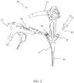
- FIG. 2 and FIG. 3illustrate respectively the proximal and distal portions of endoscope 12 and endoscopic suturing device 20.
- the endoscopic suturing device 20has an operable handle 22 which is removably coupled to endoscope 12 at a first instrument channel 24.
- a tissue grasper 26which is used to gather tissue is shown positioned within a second instrument channel 28 of endoscope 12.
- the endoscopic suturing device 20includes an elongate needle capture device 30 which is removably coupled to handle 22 and extends to the distal end of endoscope 12 slidably positioned within instrument channel 24.
- the endoscopic suturing device 20is operated by handle 22 which is proximally coupled to transmission assembly 32 which extends distally along the exterior of insertion tube 34 to the distal end 36 of endoscope 12.
- the transmission assemblyis coupled at its distal end to a cap assembly 38 which is positioned over the distal end 36 of endoscope 12.
- FIG. 3shows the distal end 40 of needle capture device 30 and the distal end helical tip 42 of tissue grasper 36 extending from instrument channels 24 and 28 respectively.
- Transmission assembly 32comprises an outer sheath 50 which is preferably formed of a flexible coil and a push rod 52 positioned within the lumen and extending from the distal end of outer sheath 50. Outer sheath 50 is fixedly secured to cap assembly 38.
- Push rod 52is coupled to a connecting member 54 via a pivot pin 56, and optionally via a push member 52a which may couple the rod 52 and the pivot pin 56.
- the connecting member 54is also connected to a pair of outer mounting brackets 58 via pivot pin 60. The mounting brackets 58 are fixedly attached to cap assembly 38.
- a pair of inner mounting brackets 62are fixedly attached to the cap assembly 38 and pivotally connected to one end of a link member 64 via pivot pin 66.
- the other end of link member 64is connected to the needle holder arm 48 via pivot pin 68.
- Needle holder arm 48is coupled to connecting member 54 via pivot pin 69.
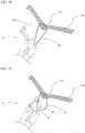
- FIG. 4the pivotable connections of connecting member 54 and link member 64 to outer and inner mounting brackets 58 and 62 respectively, allow the rotation of needle holder arm 48 when push rod 52 is axially advanced or retracted.
- FIG. 4the cap assembly 38 is shown in an open configuration with push rod 52 advanced (compare FIG. 3 where the cap assembly is in a closed configuration with push rod 52 retracted).
- FIG. 5shows the endoscopic suturing device 20 in an open configuration and from another angle where outer and inner pairs of mounting brackets 58 and 62 are more visible.
- FIG. 6shows a view of cap assembly 38 uncoupled from an endoscope.
- Cap assembly 38includes a fixedly attached insert guide 70 coupled to a flexible channel lock 72.
- Insert guide 70is a tubular projection from cap assembly 38 and is adapted to be positioned within the lumen of an endoscope instrument channel at its distal end.
- the elongate flexible channel lock 72extends from the insert guide 70 through an instrument channel and is secured to the proximal end of the instrument channel.
- the channel lock 72ensures that the cap assembly 38 does not inadvertently disengage from the distal end of the endoscope.
- channel lock 72takes the form of a small diameter single or multi stranded wire or cable formed primarily of metals or polymers. Additionally the small diameter of channel lock 72 allows room for other instruments to be positioned within the instrument channel of the endoscope.
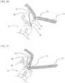
- FIG. 7illustrates needle assembly 44 which comprises a needle body 74, a needle tip 76 and suture 46.
- the suture 46may be formed of any materials commonly available for surgical suture such as nylon, polyolefins, PLA, PGA, stainless steel, nitinol and others.
- FIG. 8shows a detailed exploded view of two components of needle assembly 44.
- Needle tip 76has a sharp distal end and a hollow proximal end having a suture slot 78 through the side wall.
- Needle body 74has a rounded or blunt tapered proximal end 74a adapted to fit within the needle holder arm with the proximal end 74a presenting a should er 79 between end 74a and the remainder of the needle body 74.
- a distal end 74b of the needle body 74has a suture slot 80 adapted to concentrically engage needle tip 76.
- Flexible suture materialis positioned on the distal end of needle body 74 extending through the aligned suture slots 78 and 80.
- the needle tip 76 and needle body 74are formed from suitable biomaterials and may be made from polymers such as nylon, PEEK, PLA, PGA, PLGA or metals such as stainless steel, nitinol or titanium.
- the componentsmay be joined using standard joining techniques such as thermal bonding, ultrasonic welding laser welding, adhesives or mechanical crimping.
- FIG. 9illustrates an alternative needle assembly 82 having a needle tail 84 and a needle tip 86.
- Needle tip 86has a sharpened distal end, a suture aperture 88 and a hollow proximal end which is adapted to receive needle tail 84.
- Suture 90is positioned within the hollow end of needle tip 86 and extends through aperture 88. Needle tail 84 and suture 90 are secured in the hollow end of needle tip 86 using any of the aforementioned joining techniques.
- Needle tail 84is preferably formed in a straightened shape and of a resilient material such as nitinol. When needle tail 84 is placed in a curved needle holder arm the needle tail bends and applies a force to the inner wall of the needle holder arm maintaining the needle assembly 82 securely in place.
- FIG. 10 through FIG. 13Aillustrate alternate versions of needle assemblies for use in closing tissue defects.
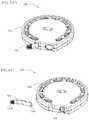
- FIG. 10shows a needle clip 92 in a straightened configuration having a body portion 94 a proximal beaded end 96 and a piercing tip 98.
- the needle clip 92is preferably formed of nitinol or other resilient material and biased into a generally circular shape. Needle clip 92 may be constrained in a generally straightened configuration but when unconstrained transitions to its biased generally circular configuration as shown in FIG. 11.
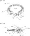
- FIG. 12shows an alternate needle clip 100 having a proximal bead 102, a piercing tip 104, an outer coil covering 106, and a body portion 108 connecting the proximal and distal ends.
- the needle clip 100also includes a securing member 110 to fixedly attach at least a portion of coil 106 to body portion 108.
- the needle clip 100is preferably comprised of nitinol or other resilient material and is biased into a generally circular shape. Needle clip 100 may be constrained in a generally straightened configuration but when unconstrained transitions to its biased generally circular configuration as shown in FIG. 13 .
- the coil 106may be formed of suitable biomaterials such as polymers of nylon, polyester, PEEK, PLA, PGA, PLGA or metals such as stainless steel, nitinol, titanium or platinum.
- the coil 106provides increased surface area for tissue in growth and encapsulation as well as distributing the force placed on tissue when closing a tissue defect.
- FIG. 13Ashows a needle clip 100 in which the coil 106 extends over the sharp piercing tip thereby shielding the tip from inadvertent damage to surrounding tissue.
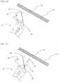
- FIG. 14shows the tissue grasper 26 which has a proximal handle 108, an elongate shaft member 110 and a helical tip 42.
- Shaft member 110is formed of a wire or multi-stranded cable or any torque transmitting configuration that provides flexibility which does not impede the steering capabilities of the endoscope.
- FIG. 15shows an enlarged view of the distal end of tissue grasper 26.
- Shaft member 110is coupled to helical tip 42 by tip coupling member 112.
- Tip coupling member 112may be fixedly joined to helical tip 42 and shaft member 110 by any of the aforementioned joining techniques.
- FIG. 16 and FIG. 17show a cinch deployment system 114 for securing suture placed at a tissue defect site.
- the cinch deployment system 114comprises a cinch assembly 116 and a cinch delivery device 118.
- the cinch delivery device 118has an elongate flexible tubular shaft 120 which is removably coupled at its distal end to cinch assembly 116 and fixedly attached at its proximal end to handle member 122.
- Handle member 122includes a slidable finger ring assembly 124 and a thumb ring 126. Slidably disposed within the lumen of tubular shaft 120 is push rod 128.
- Push rod 128extends from the distal end of tubular shaft 120 to the proximal end of tubular shaft 120 and is coupled to the slidable finger ring assembly 124 with fixation screw 130, such that movement of the finger ring assembly relative to the thumb ring 126 causes the axial movement of push rod 128 within the lumen of tubular shaft 120.
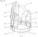
- a partially exploded view of the distal end of the cinch deployment system 114is shown in FIG. 18 .
- push rod 128extends from tubular shaft 120 and through latch assembly 129.
- Latch assembly 129is fixedly attached to tubular shaft 120 and has two latch arms 132 with latch tabs 134 at their distal ends. Latch arms 132 are biased inwardly towards the central longitudinal axis of tubular shaft 120.
- Latch assembly 129is positioned within the lumen of a latch coupling 136 and is fixedly secured.
- Latch coupling 136is configured at its distal end to engage with the proximal end of cinch 116 such that the latch arms 132 extend within the proximal lumen of cinch 116 and when push rod 128 is positioned within latch assembly 129 the latch arms 132 are forced outwardly such that the latch tabs 134 locking engage the cinch tab apertures 138.
- push rod 128is axially retracted from latch assembly 129 the latch arms 132 move inwardly towards their biased configuration causing latch tabs 134 to release their locking engagement with cinch tab apertures 138 to thereby release the cinch assembly 116.
- Cinch assembly 116has a tubular housing member 139 having cinch tab apertures 138 located at its proximal end and a suture hook 140 fixedly attached at its distal end.
- a securing clasp 142is slidably positioned within the lumen of housing member 139.
- a retention tab 144is preferably formed from the wall of housing member 139 and biased inwardly towards the central axis at of housing member 139 at its distal end.
- FIG. 21illustrates a guide tube 146 for use in an endoscopic procedure.
- Guide tube 146has a proximal end 148 including a lumen 150 that extends to the distal end 152.
- a guide tube 146is positioned in a patient to provide a conduit to a desired location while protecting the surrounding tissue from inadvertent damage.
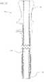
- FIG. 22 and FIG. 23show a guide tube 146 with an endoscopic suturing device 20 positioned in the lumen 150. Once the guide tube 146 is positioned at a desired treatment location within the body the distal end of the endoscopic suturing device 20 may be extended beyond the distal end of the guide tube 146.
- FIG. 24 through FIG. 34depicts a method of performing a suturing operation using an endoscopic suturing device 20.
- the endoscopic suturing device 20is positioned adjacent tissue 154 which has a tissue defect 156 to be closed.
- the endoscopic suturing device 20is in an open configuration.
- FIG. 25shows the tissue grasper 26 extended from the endoscope instrument channel such that helical tip 42 is adjacent tissue defect 156. Rotation of the tissue grasper 26 causes the helical tip 42 to securely engage the tissue 154 adjacent to the tissue defect 156.
- the tissue 154may be brought closer to the endoscope by slightly retracting the tissue grasper 26 into the instrument channel of the endoscope as shown in FIG. 26 .
- the degree of tissue retractioncorrelates to the size and location of the stitch. For instance, to have a larger amount of tissue sutured, the tissue 154 may be brought into contact with the endoscope by the tissue grasper as shown in FIG. 27 .
- the needle holder arm 48is actuated to move to a closed position causing the needle assembly 44 to pierce tissue 154.
- the suture 46is pulled through the tissue as shown in FIG. 28 .
- the control over the amount of tissue retractedallows the physician the ability to perform a partial thickness stitch within the wall of a tissue or a full thickness stitch which extends through a wall of tissue.
- the needle capture devicecaptures the needle assembly 44 by gripping it at shoulder 79 ( FIG. 7 ) and removes it from the needle holder arm 48 (not shown).
- FIG. 29shows the needle holder arm 48 moved to an open configuration and removed from tissue 154. Suture 46 remains through the tissue.
- FIG. 30shows the lengthening of the suture 46 through the tissue 154 by retracting the endoscopic suturing device 20 while retaining the needle assembly 44 within the needle capture device.
- FIG. 31shows the needle holder arm 48 moved to a closed configuration and needle assembly 44 reinserted into the needle holder arm 48 by advancing the needle capture device if the physician wishes to make another stitch. If the physician does not wish to make another stitch, the needle assembly with suture can be retracted through the endoscope channel and with both ends of the suture, a knot can be tied and pushed down the endoscope channel to the treatment site to secure the tissue.
- the suturecan be secured using a cinch deployment system.
- a cinch assembly 116 and a cinch delivery device 118may be used to capture the suture 46.
- the suturemay be pulled tight to securely close the tissue defect 156.
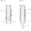
- the cinch assembly 116may be moved to a closed configuration, thereby securing the suture 46 as shown in FIG. 33 .
- the cinch delivery device 118can release the cinch assembly 116 as shown in FIG. 34 and the suture 46 may then be cut using any standard cutting means such as scissors. It is contemplated that the cinch assembly may incorporate cutting means after securing the suture.
- FIG. 35 through FIG. 38shows another method of closing a tissue defect and securing the suture.
- FIG. 35shows the endoscopic suturing device 20 having delivered a needle assembly 44 (shown schematically) and suture 46 through tissue 154 adjacent a tissue defect 156 where the needle assembly 44 is resting adjacent the surface of tissue 154.
- FIG. 36shows a cinch deployment system having a cinch assembly 116 and a cinch delivery device 118 that has grasped a portion of suture 46. The suture is pulled tight to close the tissue defect 156 while the needle assembly prevents the end of suture 46 from pulling through the tissue 154.
- the cinch assembly 116may be moved to a closed configuration, thereby securing the suture 46 as shown in FIG. 37 .
- the cinch delivery device 118can release the cinch assembly 116 as shown in FIG. 38 and the suture 46 may then be cut using any standard cutting means such as scissors.
- FIG. 39 through FIG. 42shows still another method securely closing a tissue defect.
- FIG. 39shows an endoscopic suturing device 20 having an open configuration and a needle clip 100 having a proximal bead 102 and a piercing tip 104 positioned in needle holder arm 48.
- the helical tip 42 of the tissue grasper 26has engaged tissue 154 adjacent to the tissue defect 156 and retracted the tissue towards the endoscope.
- FIG. 40shows the needle holder arm 48 in a closed configuration positioned through the tissue with the piercing tip 104 of needle clip 100 having pierced and exited the tissue.
- FIG. 41shows the needle capture device grasping the piercing tip of the needle clip 100 with the needle holder arm 48 in an open configuration and removed from tissue 154.
- the proximal bead 102 of needle clip 100is positioned adjacent the tissue site initially pierced by the piercing tip.
- FIG. 42shows the release of tissue 154 from the tissue grasper and the resilient needle clip 100 taking its pre-biased generally circular shape thereby closing the tissue defect 156.
- the application of a tissue sealant or adhesivemay be used to aid in the closing the tissue defect.
- FIG. 43shows an endoscopic suturing device 320 according to another embodiment of the present invention.
- Endoscopic suturing device 320includes a cap assembly 322 which is adapted to engage with the distal end of an endoscope, an elongate channel lock member 324 which is optionally removable from cap assembly 322, an outer sheath 326, an inner sheath 328 and an elongate flexible transmission member 330.
- cap assembly 322further includes a fixedly attached channel lock receiver 332, an endoscope channel insert guide 334, an elongate tissue guard 336, an elongate needle guard 338 which extends distally from the base of the cap assembly and houses the mechanical assembly that provides rotational motion for needle holder arm 340 as shown in FIG 44 .
- Channel insert guide 334is a tubular projection from cap assembly 322 and is adapted to be positioned within the lumen of an endoscope instrument channel at its distal end.
- the elongate flexible channel lock member 324extends from the channel lock receiver 332 through an instrument channel and is secured at the proximal end of the instrument channel.
- the channel lock member 324ensures that the cap assembly 322 does not inadvertently disengage from the distal end of the endoscope.
- channel lock member 324takes the form of a small diameter single or multi stranded wire or cable formed primarily of metals or polymers. Additionally the small diameter of channel lock 324 allows room for other instruments to be positioned within the instrument channel of the endoscope.
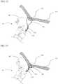
- FIGS. 44 and 45respectively show the cap assembly 322 in a needle arm 340 closed configuration and a needle arm open configuration.
- the cap assembly 322has a cap or ring element 322a having an inner diameter of approximately 13.5mm, an outer diameter of approximately 14.2mm, a height of a little over 2mm, and a portion 322b having a rim width of between 1mm and 2mm.
- the elongate tissue guard 336circumscribes approximately 50° of the ring 322a on its outside surface 336a and extends vertically approximately 9mm over the top of the ring element 322a at its middle portion.
- the inside surface 336b of the elongate tissue guard 336is generally semicircular (thereby helping define side walls 336d) and defines an approximately 4mm - 5mm opening which extends above a smaller ring 322c (see FIG. 48 ) of the cap assembly and above a channel of the endoscope into which the needle capture device (described hereinafter with reference to Figs. 55-57 ) is to be located.
- This channelmay be the same channel of the endoscope into which the channel insert guide 334 is inserted as described hereinafter.
- the top surface 336d of the elongate tissue guard 336is angled at an approximately 45° angle. With the provided arrangement, and as discussed hereinafter with reference to Figs. 63-39 , the tissue guard 336 helps fold tissue for stitching and helps prevent tissue which is drawn into the cap assembly from clogging the endoscope channel and preventing stitching.
- the elongate needle guard 338has a height of between approximately 18mm and 19mm, and forms an arched opening between two arms 338a, 338b which have outside surface spaced approximately 5mm apart from each other and inside surfaces spaced approximately 3.7mm from each other.
- the armsare joined by a top arch 338c and an optional cross-member (stop) 338d located below the arch 338c.
- a gear linkage 342described hereinafter.
- the curved needle holder arm 340is arranged such that when a needle is held in the needle holder arm 340, in a fully open position, the tip of the needle is preferably located under the arch 338c and between the arms 338a, 338b. The holder arm 340 can then rotate into a closed position through the arched opening above the gear linkage.
- Each arm 338a, 338bhas a width of approximately .64 mm and a radial thickness of approximately 2.5mm.
- FIG. 46shows a detailed exploded view of cap assembly 322.
- Needle holder arm 340includes a first end 340a which is adapted to frictionally engage a needle assembly, and a second end 340b is fixedly secured to needle arm gear link 342 (e.g., in a receiving hole 342a defined therein).
- needle holder arm 340bends through an arc of approximately 90°.
- Gear link 342is mounted between needle guard arms 338a, 338b and includes a gear portion 344 which is mounted using pivot pin 345 through mounting hole 346 in gear link 342 to mounting holes (first mounting locations) 347 defined in the housing (arms) of needle guard 338, and an arm or extension portion 343.
- Gear portion 344includes lateral gear teeth 344a.
- push member gear link 348includes gear portion 350a with lateral gear teeth 350b which mesh with gear teeth 344a, and an arm 350c.
- Gear link 348is mounted using pivot pin 351 through mounting hole 352 to mounting holes (second mounting locations) 353 defined in the housing (arms) of needle guard 338.
- Gear link 348is also coupled through mounting hole 354 in arm 350c to push member joint 356 using pivot pin 357 and mounting bracket 358.
- Push member joint 356is fixedly coupled to transmission member 330.
- cap assembly 322assembled where gear portion of gear link 348 intermeshes with gear portion of gear link 342 such that when transmission member 330 is advanced gear link 348 rotates and its gear portion causes the gear portion of gear link 342 to rotate causing needle holder arm 340 to move to a closed position.
- arm 343 of gear link 342extends around and above gear link 348 and between cross-member 338d and arch 338c.
- the arm 343 of gear link 342In the open position ( FIG. 45 ), the arm 343 of gear link 342 extends radially outward relative to needle guard arms 338a, 338b, and the back of the arm 350c may engage the edge of cross-member 338d which can act as a stop to gear movement.
- Cap assembly 322may also include a wash deflector 360 as shown in FIG. 48 .
- the wash deflectorredirects fluid from the endoscope to wash the gear mechanism to remove debris.
- the aforementioned componentsare all preferably made from biocompatible metals such as stainless steel and titanium although some high strength polymers may be suitable.
- the vertical positioning of mounting holes 347 and 353 in the needle guard arms 338a, 338breduces the profile of cap assembly 322 and facilitates delivery of the endoscopic suturing device 320 to a treatment site.
- FIGS 49 and 50illustrate views of cap assembly 322 where channel lock member 324 is optionally removably secured in channel lock receiver 332 by channel lock retention member 362.
- retention member 362is formed of a large bead fixedly secured to the distal end of channel lock member 324, whereas channel lock receiver 332 defines a groove 333 having a width smaller than the width of the bead.
- the channel lock wire or cable 324can be welded or otherwise fixed to the channel lock receiver 332 or to another part of the cap assembly.
- FIG 50An additional mechanism to increase the retention of the cap assembly to the distal end of the endoscope is show in FIG 50 where the channel insert guide 334 has a partially split structure (i.e., one or more longitudinal slits 335 are provided).
- the two portions of the splitmay be biased outwardly such that when they are placed in the instrument channel of the endoscope they apply and outward force to the inner wall of the channel thereby aiding in the retention of the cap assembly to the distal end of the endoscope.
- FIGS. 51 and 52show how tension is applied to channel lock member 324 and maintained at the proximal end of the endoscope by using a channel lock tensioner 365 that secures the proximal channel lock retention member 366 secured to the proximal end of the channel lock member.
- the channel lock tensioner 365includes a bayonet lock connector 370, which couples to the endoscope instrument channel and a spring 372 which supports a tensioner housing 374 coupled to a rotatable tensioning wheel 376 having a tab member 378.
- the proximal end of channel lock member 324is threaded through tensioner housing 374 and through a valve located at the top of the housing, and is positioned within a tab receptacle 380.
- the tab receptacle 380secures channel lock retention member 366 to the tensioner wheel 376.
- the tensioner wheel 376can then be rotated (e.g., clockwise) to apply the appropriate tension on the channel lock member and then locked into place by a locking element (not shown).
- Spring 372is used to compensate, by compressing, for the bending of the endoscope to maintain a constant tension on the channel lock member.
- the springcan be provided on the wheel 376 to spring load the wheel toward a desired position (e.g., the position of FIG. 51 ). As the channel lock member 324 is bent along with the scope through a tortuous path, wheel 376 can rotate against the force of the spring to maintain the desired tension on the channel lock member 324.
- FIG. 53illustrates needle assembly 400 which comprises suture 402, a needle tip 404, a lock gap 405 and a needle body 406.
- the suture 402may be formed of any materials commonly available for surgical suture such as nylon, polyolefins, PLA, PGA, stainless steel, nitinol and others.
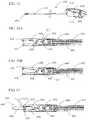
- FIGS. 54A through 54Cshow detailed exploded views of the components of needle assembly 400.
- Needle tip 404has a sharp distal end and a hollow proximal end with a swage lip 408.
- Needle body 406has a proximal end adapted to fit within the needle holder arm 340 and a distal end having a suture slot 410.
- Needle body 406is adapted to concentrically engage needle tip 404 and create lock gap 405.
- Flexible suture material 402is positioned on the distal end of needle body 406 extending through the suture slot 410.
- the needle tip 404 and needle body 406are formed from suitable biomaterials and may be made from polymers such as nylon, PEEK, PLA, PGA, PLGA or metals such as stainless steel, nitinol or titanium.
- the componentsmay be joined using standard joining techniques such as thermal bonding, ultrasonic welding laser welding, adhesives or mechanical crimping.
- FIG. 55illustrates a needle capture device 450, which includes an elongate catheter or tube 452 having at its distal end a needle capture assembly 454 and at is proximal end a button actuator 456 coupled to handle assembly 458.
- the needle capture device 450is a 3mm tool in that the tube 452 and the distal end needle capture assembly 454 are preferably at most 3mm in diameter.
- the handle assembly 458is preferably adapted to be coupled to the handle assembly operating the needle holder arm of the endoscopic suturing device 320 for ease of use.
- handle assembly 458is provided with a deflecting tooth lock 459a and a generally rigid tooth 459b which are arranged to engage with reciprocal cavity and locking element in the handle assembly 600 of the suturing device 320 as discussed below with reference to Figs. 58 and 59A-59C .
- FIGS. 56A and 56Bshow an enlarged partial cross-sectional view of needle capture assembly 454 and the distal end 460 of tube 452 in closed and open configurations respectively.
- Slidably positioned within the lumen of tube 452is push rod or cable 462 which has a proximal end mechanically coupled to button actuator 456 and a distal end coupled to actuator pin 464.
- Actuator pin 464is positioned within an angled slot 465 defined in lever arm 466 adjacent fixed pivot pin 468.
- an interlock feature 470At the distal end of lever arm 466.
- the distal inner portion of needle capture assembly 454forms needle receptacle 472.
- Button actuator 456incorporates a spring assembly which places push rod 462 under a tension load thereby causing lever arm 466 to remain in an engaged or closed configuration as shown in FIG. 56A .
- button actuator 456When button actuator 456 is depressed, push rod 462 is advanced, there by causing lever arm 466 and interlock feature 470 to a disengaging or open configuration as shown in FIG. 56B.
- FIG. 57illustrates needle assembly 400 positioned within needle receptacle 472 of needle capture assembly 454. As shown, needle assembly 400 is secured in place by the interlocking engagement of interlock feature 470 and lock gap 405. In this configuration needle capture device 450 can be used to deliver the needle through the instrument channel of the endoscope to load the needle assembly into needle holder arm 340.
- a handle assembly 600 for the endoscopic suturing device 320is seen in FIG. 58 and 59A-59C .
- the handle assembly 600includes a first stationary handle 604 and a second rotatable handle 608 which is rotatably coupled to stationary handle by pivot axle 612.
- the rotatable handle 608is spring-biased to the open position seen in FIG. 58 by a spring 614 which sits and is fixed between the handles.
- the stationary handle 604defines a proximal cavity 616 for receiving the handle assembly 458 of the needle capture device 450. Extending from the stationary handle 604 is a tube 618 which terminates in a port 620.
- Port 620includes a fluid valve 622 and a mechanical bayonet lock 624 for coupling to the proximal end of an endoscope. Also extending from the stationary handle is sheath 328 which houses the transmission wire 330. Second handle 608 defines a fingers grip section 626, and ratcheted locking element 628 at its proximal end. As described hereinafter, the rotatable second handle 608 is coupled to the transmission wire 330. Movement of the rotatable handle towards the fixed handle causes axial movement (retraction) of the transmission wire 330. Movement of the rotatable handle away from the fixed handle causes axial movement (extension) of the transmission wire 330 in an opposite direction.
- FIG. 59Apivotably coupled to the inside of first handle 604 by pivot pin 632 is an actuation pivot element 634.
- the transmission wire 330is coupled to the actuation pivot element 634 at a second location 636 by a spring 638 which can move in a predetermined distance in a cavity 639 defined by fixed handle 604.
- the rotatable handle 608is also coupled to the actuation pivot element 634 at a third location 640 by bracket 642 which is coupled to the rotatable handle 608 by post 644.
- rotation of the handle 608i.e., squeezing
- bracket 642to pull location 640 of the actuation pivot element 634 downward.
- Movement of location 640 downwardis accompanied by clockwise rotation of the actuation pivot element 634 about pivot pin 632, and thus backward (clockwise) movement of the connection between spring 638 and the actuation pivot element 634 at location 636. Movement of spring 638 backward pulls transmission wire 330 backward.
- FIG. 59AAlso seen in FIG. 59A is the interaction of handle assembly 600 with the handle assembly 458 of the needle capture device 450. More particularly, the stationary handle 604 is provided with a catch 648 which extends into cavity 616 and is designed to engage the flexible tooth (latch) 459a of the needle capture device handle assembly 458. In addition, cavity 616 has a bottom proximal ledge 650 for receiving rigid tooth 459b. Tube 618 which extends out of the stationary handle 604 extends into a tubular cavity 654 of the stationary handle 604 which houses a spring 656, thereby spring loading tube 618 outward.
- the distal end of the needle capture assemblyis threaded into cavity 616 of the stationary handle 604, tubular cavity 654, tube 618, port 620 and then into the endoscope.
- the needle capture assembly 454is pushed through until the handle 458 engages the cavity 616 of the stationary handle 604.
- rigid tooth 459baligns with ledge 650, and flexible latch 459a engages catch 648, thereby locking the needle capture device 450 in place.
- Cable 462 of the needle capture device 450 with sheeth 452extends from the button actuator 457 through the tubular cavity 654, through the tube 618, and through and out of the port 620.
- button 456is pushed as previously described. Disconnection of the needle capture device 450 from the handle assembly 600 is obtained by pressing down on a relieved portion 459c of the handle 458 adjacent and proximal the latch 459a, thereby causing the latch to disengage from the catch 648, and pulling proximally on the handle 458.
- the needle capture device handle 458is preferably provided with a ratchet locking extension or (hooked) tooth 459d.
- the handles 604 and 608may be locked into place in a closed position by engaging ratcheted locking element or tooth 628 on rotatable handle 608 with the similar ratcheted locking extension or tooth 459d of the needle capture assembly 450 (which in turn is locked in stationary handle 604) as seen best in FIG. 59C .
- the teeth 628 and 459dare generally laterally offset, but include hooked portions which after sliding past each other, will engage or grip each other, thereby locking in place. Disengagement is obtained by applying a relative lateral force to one or both of the handles.
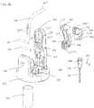
- FIG. 60AAn innovative suture dispenser 500 having a dispenser body 502 and a removable needle shield tab 504 is shown in FIG 60A .
- the suture dispenser 500is shown in FIG 60B with the needle shield tab 504 removed from the dispenser revealing a needle retaining member 506.
- FIG. 60Cshows an exploded perspective view of the components.
- Suture dispenser 500includes a lower body 508 and upper body 510 which together form a cavity which houses suture spool 512 containing suture 402, needle shield 504 and needle retaining member 506.
- Wall 513bis a low wall which is placed in between walls 513a and 513c and is connected to the angled portion 513e of wall 513a. Wall 513b effectively forms two grooves with the first groove seating the needle retaining member 506 and holding it in place and the second groove seating a portion of the needle shield tab 504. Needle shield tab, however extends out of a radial opening or orifice in outer wall 513c and can be pulled out (i.e., can slide out) completely to reveal a receiving cavity 514 in the needle retaining member 506.
- the outer wall 513cis also provided with an opening or orifice 513f in front of the receiving cavity 514.
- the suture dispenser 500 and most of its componentsare easily fabricated at low cost using suitable polymers, such as polyethylene, polypropylene or polystyrene, injection molding and preferably designs which snap together (e.g., latches 508c and hollow receiving post 508d on lower body 508, and catches 510c and post (not shown) on upper body 510).
- needle shield 504is preferably provided with prongs 504a.
- the prongsare squeezably held between ribs (not shown) extending from the lower and upper bodies 508, 510 in order to hold the needle shield 504 in place.
- the prongsare resilient, application of force to the tab portion 504b of the needle shield 504, permits the needle shield 504 to be removed from the dispenser body 502.
- needle retaining member 506includes a needle receiving cavity 514 as shown in FIGS. 61A and 61B where removable needle assembly 400 is held.
- needle body 406is frictionally held within an orifice 514a defined in the body of retaining member 506 (in much the same manner it is frictionally held in the needle holder arm 340 ( FIG. 46 ) and the needle is connected to suture 402 which is wound on the suture spool.
- Needle tip 404is accessible to the needle capture assembly 454 through needle receiving cavity 514; i.e., the cavity provides room around the needle tip to permit the needle capture assembly to enter the cavity and grab the needle. Also as shown in FIG.
- the needle retaining member 506has laterally elongated upper and lower flanges 514b which are receiving and seat in the grooves formed by the walls 513a, 513b of the lower and upper bodies 508, 510 of the suture dispenser 500.
- the body of the needle retaining memberhas a cylindrical portion which extends backward through the orifice 513d of the inner wall 513a.
- FIGS. 62A and 62Bshow the suture dispenser 500 receiving the needle capture assembly 454 of needle capture device 450.
- FIG. 62Bshows a partial cross section view of the needle capture assembly 454 interlockingly engaged with the needle for removal from the dispenser.
- FIG. 63 through FIG. 69depicts a method of performing a suturing operation using an endoscopic suturing device 320 of the present invention.
- the endoscopic suturing device 320is positioned adjacent tissue 154 which has a tissue defect 156 to be closed.
- the endoscopic suturing device 320is in an open configuration and the tip of needle assembly 400 is shrouded by needle guard 338.
- FIG. 64shows the tissue grasper 26 is extended from the endoscope instrument channel such that helical tip 42 is adjacent tissue defect 156. Rotation of the tissue grasper 26 causes the helical tip 42 to securely engage the tissue 154 adjacent to the tissue defect 156.
- the tissue 154may be brought closer to the endoscope by slightly retracting the tissue grasper 26 into the instrument channel of the endoscope as shown in FIG. 65 .
- the needle guard 338prevents the tissue from dragging against the tip of needle assembly 400, thereby reducing inadvertent tissue damage.
- the degree of tissue retractioncorrelates to the size and location of the stitch. For instance to have a larger amount of tissue sutured, the tissue grasper may bring the tissue 154 close to the endoscope as shown in FIG. 66 .
- the needle holder arm 340is actuated to move to a closed position causing the needle assembly 400 to pierce tissue 154.
- the angled portion of tissue guard 336provides support for the tissue allowing the needle to more easily penetrate the tissue as shown in FIG. 67 .
- the suture 402is pulled through the tissue as shown in FIG. 68 .
- the control over the amount of tissue retractedallows the physician the ability to perform a partial thickness stitch within the wall of a tissue or a full thickness stitch which extends through a wall of tissue.
- the needle capture devicecaptures the needle assembly 400 and removes it from the needle holder arm 340(not shown).
- FIG. 69shows the needle holder arm 340 moved to an open configuration and removed from tissue 154. Suture 402 remains through the tissue.
- the needle holder armcan be reloaded with the needle assembly without needing to remove the endoscopic suturing device from the body as previously described. If only one stitch is required the suture may be tied into a surgical knot or a cinch device used to secure the suture, thereby closing the tissue defect.
- each treatment device described abovecan be used together with a rigid endoscope, trocar, or the like as well as flexible endoscopes.
- each treatment device described abovecan be used together with a rigid endoscope, trocar, or the like as well as flexible endoscopes.
- particular sizes and shapeswere described with respect to the end cap, needle guard, tissue guard, etc. of a particular embodiment, other sizes and shapes could be utilized.
Landscapes
- Health & Medical Sciences (AREA)
- Life Sciences & Earth Sciences (AREA)
- Surgery (AREA)
- Animal Behavior & Ethology (AREA)
- Public Health (AREA)
- Engineering & Computer Science (AREA)
- Biomedical Technology (AREA)
- Heart & Thoracic Surgery (AREA)
- Medical Informatics (AREA)
- Molecular Biology (AREA)
- Veterinary Medicine (AREA)
- General Health & Medical Sciences (AREA)
- Nuclear Medicine, Radiotherapy & Molecular Imaging (AREA)
- Dentistry (AREA)
- Physics & Mathematics (AREA)
- Biophysics (AREA)
- Optics & Photonics (AREA)
- Pathology (AREA)
- Radiology & Medical Imaging (AREA)
- Surgical Instruments (AREA)
- Endoscopes (AREA)
Description
- This application claims priority from provisional patent application
U.S. 61/073,340 file June 17, 2008 U.S. 61/162,249 filed March 20, 2009 - The present invention relates to a treatment device which can be inserted into a body through a natural orifice with an endoscope or other steerable guide member. The present invention may be used to perform suturing on the tissue of a mammal, whether human or not, and whether or not alive, but is not limited thereto.
U.S. Pat No. 7,344,545 (Olympus Corporation) discloses an endoscopic suturing system having many embodiments to perform a surgical operation. This suturing system generally comprises an assembly having first and second arms which are actuatable by a push rod to rotatably approach each other while one arm grasps tissue and the second arm drives a curved needle through the tissue. The system also includes a needle recovery member requiring a rigid alignment with the curved needle arm. While this system affords the ability to grasp thick tissue, the tissue grasping arm and the arrangement of the needle recovery member provides bulk to the system making it difficult to use in endoscopic procedures.- US Pat Appln Pub No.
US2005/0149067 A1 discloses an endoscopic suturing system having a needle holder arm that is actuated directly by a push rod to move a needle to puncture tissue. Movement and control of the needle is directly linked to the movement of the push rod. - The treatment device of the invention is defined in
claim 1. Preferred embodiments are defined in the dependent claims. - The present invention provides an endoscopic treatment device having a structure enabling a small profile for delivery while providing both a large opening and closing angle and producing a large needle force for piercing tissue to perform a surgical operation such as tissue approximation and suturing within the body.
- In accordance with an aspect of the present disclosure there is provided an endoscopic treatment device which is used to perform treatment in a body while being operated outside the body. The treatment device comprises a flexible member coupled to a proximal handle assembly for operation outside of the body and a distal cap assembly where the cap assembly is adapted to engage the distal end of an endoscope. The flexible member is connected to a link mechanism and is actuated to cause a needle assembly having a needle holder arm and needle which are coupled to the cap assembly to move in a direction to puncture tissue and a direction to be removed from tissue.
- According to another aspect of the present disclosure there is provided an endoscopic treatment system for use with an endoscope having a cap assembly adapted to be positioned at the distal end of an endoscope where the cap assembly has at least one mounting bracket which is fixedly attached. A transmission member with a flexible structure has a distal end portion that is inserted into a body and is capable of being operated outside the body by a proximal portion coupled to a handle assembly. A push rod is coupled to the distal end portion of the transmission member. A connecting member having a needle holder arm is coupled to the push rod and pivotally coupled to the mounting bracket. A removable needle is connected to the needle holder arm and is adapted to pierce tissue. When the push rod is actuated by the transmission member, the connecting member moves the needle holder arm in a direction to pierce tissue or in a direction to remove it from tissue. An elongate needle capture device is positioned within the instrument channel of the endoscope and has a distal end adapted to receive and grasp the needle and a proximal end coupled to a handle assembly.
- In accordance with another aspect of the present disclosure there is provided a removable needle assembly having a needle tip member and a needle base member. The needle tip member has a sharpened end which is adapted to pierce tissue and a hollow end to receive the needle base member. The needle tip member also includes an aperture which may take the form of a longitudinal slot through the wall adjacent the hollow end which is adapted to allow suture to extend there from. The needle base member has a first end which is adapted to engage the hollow end of the needle tip member and a second end which is adapted to removably engage a needle holder arm. The needle base member further includes a stop member which when coupled with the needle holder arm limits the depth to which the needle base is inserted into the needle holder arm. The coupling engagement of needle tip member and the first end of the needle base member are adapted to secure a length of suture material to the needle assembly and allow it to extend through the aperture adjacent the hollow end of the needle tip member.
- In accordance with still another aspect of the present disclosure there is provided a needle clip assembly having first and second ends where a needle tip adapted for piercing tissue is positioned at the first end and a tissue stop member is positioned at the second end. The needle clip assembly has a constrained first configuration and an unconstrained second configuration where the needle clip assembly is resiliently biased to move from the first configuration to the second configuration. The constrained first configuration may take the form of a generally straightened elongate member. The unconstrained second configuration may take the form of a loop, helix or substantially closed loop form.
- In accordance with yet another aspect of the present disclosure there is provided an endoscopic treatment system for use with an endoscope having a cap assembly adapted to be positioned at the distal end of an endoscope where the cap assembly has two pair of fixedly attached mounting brackets. A transmission member with a flexible structure has a distal end portion that is inserted into a body and is capable of being operated outside the body. A push rod is coupled to the distal end portion of the transmission member. A connecting member having a needle holder arm is coupled to the push rod and pivotally coupled to the outer pair of mounting brackets. A link member having two ends is pivotally coupled to the inner pair of mounting brackets at one end and pivotally coupled to the needle holder arm at the other end. A removable needle is connected to the needle holder arm and is adapted to pierce tissue. When the push rod is actuated by the transmission member, the connecting member moves the needle holder arm in a direction to pierce tissue or a direction to remove it from tissue. An elongate needle capture device is positioned within the instrument channel of the endoscope having a proximal handle and a distal end adapted to receive and grasp the needle.
- In accordance with yet another aspect of the present invention there is provided a combination handle assembly adapted to operate the movement of the transmission member thereby opening and closing the needle arm and adapted to operate the needle capture device to thereby grasp and release the needle. The handle assembly includes a handle main body coupled to an endoscope channel coupling which is adapted to engage the instrument channel of an endoscope. An elongate needle capture device includes a proximal housing which is removably coupled to the handle main body and a distal end is which positioned through the endoscope channel coupling into the instrument channel of an end. An actuatable trigger lever is coupled to handle main body and operates the transmission member to axially advance or retract the transmission member.
- In accordance with another aspect of the present disclosure there is provided an endoscopic treatment system that further includes a tissue grasping member. The tissue grasping member takes the form of an elongate member having proximal and distal ends and is positioned with a channel of an endoscope. The distal end of the tissue grasping member may take the form of a helix or tapered spiral in which rotation of the helix when at a desired site adjacent tissue, causes the helix to substantially engage the tissue and allow the tissue to be retracted.
- In accordance with still another aspect of the present invention there is provided an endoscopic treatment system that further includes a tissue grasping member. The tissue grasping member takes the form of an elongate member having proximal and distal ends and is positioned with a channel of an endoscope. The distal end of the tissue grasping member may take the form of a pair of jaws such that when at a desired site adjacent tissue, operation of the jaws causes the jaws to substantially engage the tissue and allow the tissue to be retracted.
- In accordance with another aspect of the present disclosure there is provided an endoscopic treatment device which is used to perform treatment in a body while being operated outside the body. The treatment device comprises a flexible member coupled to a proximal handle assembly for operation outside of the body and a distal cap assembly where the cap assembly is adapted to engage the distal end of an endoscope. The cap assembly includes an elongate channel lock member having one end which is fixedly attached to the cap assembly and extends through the channel of an endoscope and is removably secured to the proximal end of the endoscope channel. The channel lock member may take the form of a small diameter flexible wire assembly or wire braid assembly.
- In accordance with yet another aspect of the present disclosure there is provided an endoscopic suturing system for use with an endoscope having a cap assembly adapted to be positioned at the distal end of an endoscope where the cap assembly defines mounting locations. A transmission member with a flexible structure has a distal end portion that is inserted into a body and is capable of being operated outside the body. A push member is optionally coupled to the distal end portion of the transmission member. A link member having a geared portion is coupled to the push member or the transmission member and pivotally coupled at a first mounting location. A connecting member having a geared portion and a needle holding arm at one end is pivotally coupled at a second mounting location such that the geared portions of the link member and the connecting member intermesh.
- In accordance with another aspect of the present disclosure there is provided an endoscopic suturing system for use with an endoscope having a cap assembly adapted to be positioned at the distal end of the endoscope where the cap assembly includes an elongate needle guard. The needle guard generally extends from a base of the cap in a direction distal to the end of the endoscope. Preferably the needle guard extends in a distal direction parallel to the axis of the endoscope. The needle guard is adapted to prevent tissue from inadvertently contacting the needle tip while the needle tip is in an open position and the tissue is being positioned for suturing.
- In accordance with another aspect of the present disclosure there is provided an endoscopic suturing system for use with an endoscope having a cap assembly adapted to be positioned at the distal end of the endoscope where the cap assembly includes an elongate channel guard. The channel guard generally extends from a base of the cap in a direction distal to the end of the endoscope and is coaxial with the endoscope channel which used by the needle capture device. The channel guard is adapted to aid in suturing by positioning tissue a sufficient distance away from the end of the endoscope channel allowing for better visualization and providing a surface to support the tissue during the suturing operation. Preferably, the distal end of the channel guard is inclined to provide a plane which is generally perpendicular to the needle tip as the needle tip intersects the plane along the needle suturing path. Preferably, the minimum length that the channel guard extends from the cap is related to the field of view from the endoscope such that minimum length allows sufficient tissue to be visualized when the tissue is placed in a position for suturing.
- In accordance with another aspect of the present disclosure there is provided an endoscopic treatment device which is used to perform treatment in a body while being operated outside the body. The treatment device comprises a flexible member coupled to a proximal handle assembly for operation outside of the body and a distal cap assembly where the cap assembly is adapted to engage the distal end of an endoscope. The cap assembly includes an elongate channel lock member having one end which is removably secured to the cap assembly and extends through the channel of an endoscope and is removably secured to the proximal end of the endoscope channel by a tensioning assembly. The channel lock member may take the form of a small diameter flexible wire assembly or wire braid assembly. Preferably, the channel lock member includes retaining members fixedly secured to each end. The tensioning assembly includes a bayonet lock fitting adapted to engage a bayonet prong on the endoscope, a housing member, a rotatable wheel member having a tab member and a tensioner member. The proximal end of the channel lock member is secured to the tab member of the rotatable wheel such that rotation of the wheel applies a preset tension to the channel lock member. The housing member of the tensioning assembly in conjunction with the tensioner member, preferably formed of a spring, maintains the tension on the channel lock member by resisting compression during normal bending operation of the endoscope.
- According to another aspect of the endoscopic treatment system of the present disclosure there is provided a cinch system including a cinch delivery device and a cinch device. The cinch delivery device takes the form of an elongate tubular member having proximal end coupled to a handle assembly and a distal end. The distal end of the cinch delivery device is removably coupled to the cinch device. The cinch device has a housing that incorporates a suture capture hook at is distal end for capturing suture that has been placed through tissue. A cinch plug is positioned within the cinch housing and is movable from a first suture non-retaining position to a second suture retaining position for securing suture in a fixed position by operating the handle assembly. Once suture has been secured by the cinch plug in the cinch housing the handle assembly may be operated to uncouple the cinch device from the cinch delivery tool.
- According to still another aspect of the present disclosure, there is provided a suturing method using an endoscopic suturing system. This method comprises the steps of:
- (1) inserting a guide tube and/or endoscope into a body with a suturing device coupled to the endoscope and or guide tube;
- (2) opening a needle arm of the suturing device having a removable needle;
- (3) pushing the needle against tissue at a desired suture site;
- (4) closing the needle arm of the suturing device;
- (5) piercing the tissue with the needle;
- (6) recovering the needle by using a needle capture device;
- (7) removing the needle from the tissue;
- (8) opening the needle arm to remove it from tissue;
- (9) closing the needle arm; and
- (10) removing the suturing device from the body.
- According to yet another aspect of the present invention, there is provided a suturing method using an endoscopic suturing system including a tissue grasper. This method comprises the steps of:
- (1) inserting a guide tube into a body;
- (2) inserting a suturing device coupled to an endoscope into the guide tube and into the body;
- (3) opening a needle arm of the suturing device having a removable needle;
- (4) engaging a tissue adjacent a desired suture site using a tissue grasper;
- (5) pushing the needle against tissue at a desired suture site;
- (6) closing the needle arm of the suturing device;
- (7) piercing the tissue with the needle;
- (8) recovering the needle by using a needle capture device;
- (9) removing the needle from the tissue;
- (10) opening the needle arm to remove it from tissue;
- (11) releasing the tissue from the tissue grasper;
- (12) closing the needle arm; and
- (13) removing the suturing device from the body.
- According to another aspect of the present disclosure, there is provided a suturing method of performing a running stitch using an endoscopic suturing system. This method comprises the steps of:
- (1) inserting a guide tube into a body;
- (2) inserting a suturing device coupled to the endoscope into the guide tube and inserting the suturing device into the body;
- (3) opening a needle arm of the suturing device having a removable needle;
- (4) pushing the needle against tissue at a desired suture site;
- (5) closing the needle arm of the suturing device;
- (6) piercing the tissue with the needle;
- (7) recovering the needle by using a needle capture device;
- (8) removing the needle from the tissue;
- (9) opening the needle arm to remove it from tissue;
- (10) closing the needle arm;
- (11) inserting the needle into the needle arm endoscopically using the needle capture device;
- (12) performing steps (3) through (11) as needed.
- According to still yet another aspect of the present disclosure there is provided a method of securing tissue using an endoscopic suturing system including a resilient pre-biased needle clip and a tissue grasper. This method comprises the steps of:
- (1) inserting a guide tube into a body;
- (2) inserting a suturing device coupled to the endoscope into the guide tube and inserting the suturing device into the body;
- (3) opening a needle holding arm of the suturing device having a removable needle clip;
- (4) engaging a tissue adjacent a desired suture site using a tissue grasper
- (5) pushing the needle clip against tissue at a desired suture site;
- (6) closing the needle holding arm of the suturing device;
- (7) piercing the tissue with the needle clip;
- (8) grasping the needle clip tip using a needle capture device;
- (9) opening the needle holding arm to remove it from tissue;
- (10) releasing the needle clip from the needle capture device
- (11) releasing the tissue from the tissue grasper;
- (12) closing the needle holding arm; and
- (13) removing the suturing device from the body.
- Advantages of the invention will be set forth in the description which follows, and in part will be obvious from the description, or may be learned by practice of the invention. Advantages of the invention may be realized and obtained by means of the instrumentalities and combinations particularly pointed out hereinafter.
- The accompanying drawings, which are incorporated in and constitute a part of the specification, illustrate embodiments of the invention or embodiments of the present disclosure which are not covered by the invention as defined in the claims, and together with the general description given above and the detailed description of the embodiments given below, serve to explain the principles of the invention.
FIG. 1 is an illustrative view showing an endoscopic suturing system with endoscope system;FIG. 2 is an enlarged view of the proximal portion of an endoscope and an endoscopic suturing system shown inFIG. 1 ;FIG. 3 is a perspective enlarged view of the distal end of an endoscopic suturing system according to an embodiment of the present disclosure where the actuating arm of the suturing device is closed;FIG. 4 is a perspective enlarged view of the distal end of an endoscopic suturing system according to an embodiment of the present disclosure where the actuating arm of the suturing device is open;FIG. 5 is another perspective enlarged view of the distal end of an endoscopic suturing system according to an embodiment of the present disclosure where the actuating arm of the suturing device is open;FIG. 6 is a perspective enlarged view of the cap assembly of an endoscopic suturing system according to an embodiment of the present disclosure where the actuating arm of the suturing device is closed;FIG. 7 is an illustrative view of a needle assembly for use with an endoscopic suturing device according to an embodiment of the present invention;FIG. 8 is an exploded view of a needle assembly ofFIG. 7 ;FIG. 9 is an illustrative view of a needle assembly for use with an endoscopic suturing device according to another embodiment of the present invention.FIG. 10 is a view of an endoscopic clip for use with an endoscopic suturing system according to an embodiment of the present disclosure;FIG. 11 is a view of the preferentially biased resilient endoscopic clip ofFIG. 10 when unconstrained.FIG. 12 is a view of an endoscopic clip for use with an endoscopic suturing system according to another embodiment of the present disclosure;FIG. 13 is a view of the preferentially biased resilient endoscopic clip ofFIG. 12 when unconstrained;FIG. 13A is a view of the preferentially biased resilient modified endoscopic clip ofFIG. 13 when unconstrained and having a coil that extends over the sharp tip;FIG. 14 is a view of the helical tissue grasper;FIG. 15 is an enlarged view of the distal end of the helical tissue grasper;FIG. 16 is a top view of a cinch device and cinch delivery device;FIG. 17 is a side view of a cinch device and cinch delivery device;FIG. 18 is an enlarged exploded view of the distal end of the cinch and cinch delivery device;FIG. 19 is an enlarged view of the cinch device in an open configuration;FIG. 20 is an enlarged view of the cinch device in a closed configuration;FIG. 21 is a sectional view of an endoscopic guide tube;FIG. 22 is a partial sectional view of an endoscopic suturing system disposed within the lumen of an endoscopic guide tube;FIG. 23 is a partial sectional view of an endoscopic suturing system extending from the distal end of an endoscopic guide tube;FIG. 24 through FIG. 34 illustrate steps in a surgical suturing procedure using an endoscopic suturing system according to an embodiment of the present disclosure whereinFIG. 24 is a view of a step in which a an endoscopic suturing device is positioned adjacent a wound at a desired treatment location;FIG. 25 is a view of a step in which a tissue grasper is extended adjacent a wound at a desired treatment location;FIG. 26 is a view of a step in which a tissue grasper engages tissue and is slightly retracted to bring tissue closer to the endoscope;FIG. 27 is a view of an alternative step in which a tissue grasper engages tissue and is substantially retracted to bring tissue in contact with the endoscope;FIG. 28 is a view of a step in which the needle pierces tissue;FIG. 29 is a view of a step in which the needle holder arm is removed from the tissue depositing a suture through the tissue;FIG. 30 is a view of a step in which the tissue grasper disengages the tissue;FIG. 31 is a view of a step in which the needle is reloaded into the needle holder arm;FIG. 32 is a view of a step in which a cinch device captures suture;FIG. 33 is a view of a step in which the suture is tightened using the cinch device to thereby close the wound;FIG. 34 is a view of a cinch device released from the cinch delivery device;FIG. 35 through FIG. 38 illustrate steps in a surgical suturing procedure using an endoscopic suturing system according to another embodiment of the present disclosure whereinFIG. 35 is a view of a step in which a an endoscopic suturing device has delivered a needle through tissue at a desired treatment location;FIG. 36 is a view of a step in which a cinch device captures suture;FIG. 37 is a view of a step in which the suture is tightened using the cinch device to thereby close the wound;FIG. 38 is a view of a cinch device released from the cinch delivery device;FIG. 39 through FIG. 42 illustrate steps in a surgical suturing procedure using an endoscopic suturing system according to yet another embodiment of the present disclosure whereinFIG. 39 is a view of a step in which an endoscopic suturing device having a needle clip is positioned at a desired treatment location;FIG. 40 is a view of a step in which the needle clip pierces tissue;FIG. 41 is a view of a step in which the needle holder arm is removed from the tissue depositing the needle clip through the tissue;FIG. 42 is a view of a step in which the tissue grasper disengages the tissue and the needle clip close the wound;FIG. 43 is an illustrative view showing an endoscopic suturing system with a channel lock member including a treatment device according to an embodiment of the present invention;FIG. 44 is a perspective enlarged view of the cap assembly of an endoscopic suturing system according to an embodiment of the present invention where the actuating arm of the suturing device is closed;FIG. 45 is a perspective enlarged view of the cap assembly of an endoscopic suturing system according to an embodiment of the present invention where the actuating arm of the suturing device is open;FIG. 46 is a perspective enlarged exploded view of the cap assembly of an endoscopic suturing system according to an embodiment of the present invention;FIG. 47 is another perspective enlarged view of the cap assembly of an endoscopic suturing system according to an embodiment of the present invention where the actuating arm of the suturing device is closed;FIG. 48 is yet another perspective enlarged view of the cap assembly of an endoscopic suturing system according to an embodiment of the present invention where the actuating arm of the suturing device is closed;FIG. 49 is still another perspective enlarged view of the cap assembly of an endoscopic suturing system according to an embodiment of the present invention;FIG. 50 is still yet another perspective enlarged view of the cap assembly of an endoscopic suturing system according to an embodiment of the present invention;FIG. 51 is perspective enlarged view of the channel lock tensioner assembly in a first configuration according to an embodiment of the present invention;FIG. 52 is perspective enlarged view of the channel lock tensioner assembly in a second configuration according to an embodiment of the present invention;FIG. 53 is an illustrative view of a needle assembly according to an embodiment of the present invention;FIGS. 54A through 54C illustrate steps in assembling the components of a needle assembly according to an embodiment of the present invention;FIG. 55 is an illustrative view of a needle capture device according to an embodiment of the present invention;FIGS. 56A and 56B are enlarged partial section views of the distal end of a needle capture device, whereFIG 56A illustrates the needle capture assembly in a normally closed configuration andFIG. 56B illustrates the needle capture assembly in an open configuration;FIG. 57 is an enlarged partial section view of the needle capture assembly interlockingly engaging a needle assembly according to an embodiment of the present invention;FIG. 58 is a perspective view of a handle assembly of an endoscopic suturing system according to an embodiment of the present invention;FIG. 59A is a cross-sectional view of the handle assembly ofFIG. 58 in a closed position with the handle assembly of the capture assembly locked in position therein;FIG. 59B is a perspective view of the arrangement ofFIG. 59A ;FIG. 59C is a perspective view of the handle assembly ofFIG. 58 in an open position and with the handle assembly of the capture assembly locked in position therein;FIG. 60A is a perspective view of a molded suture dispenser including a removable needle shield tab;FIG. 60B is a perspective view of the suture dispenser where the needle shield tab has been removed to provide access to the needle retaining member;FIG. 60C is an exploded perspective view illustrating the components of the molded suture dispenser;FIG. 61A is an enlarged perspective view of the needle retaining member;FIG. 61B is an enlarged partial cross-sectional view of the needle retaining member securing the removable needle assembly;FIG. 62A is a perspective view illustrating the needle capture device engaging the suture dispenser;FIG. 62B is an enlarged partial cross-sectional view of the needle capture assembly interlockingly engaging the removable needle assembly positioned within the needle retaining member of the suture dispenser;FIG. 63 through FIG. 69 illustrate steps in a surgical suturing procedure using an endoscopic suturing system according to another embodiment of the present invention whereinFIG. 63 is a view of a step in which a an endoscopic suturing device is positioned adjacent a wound at a desired treatment location;FIG. 64 is a view of a step in which a tissue grasper is extended adjacent a wound at a desired treatment location;FIG. 65 is a view of a step in which a tissue grasper engages tissue and is slightly retracted to bring tissue closer to the endoscope;FIG. 66 is a view of an alternative step in which a tissue grasper engages tissue and is substantially retracted to bring tissue in contact with the endoscope;FIG. 67 is a view of a step in which the needle partially pierces tissue;FIG. 68 is a view of a step in which the needle completely pierces tissue;FIG. 69 is a view of a step in which the needle holder arm is removed from the tissue depositing a suture through the tissue;- As shown in
FIG.1 anendoscope system 10 which comprises anendoscope 12, avideo display unit 14, animage processing device 16, alight source 17, asuction device 18 is used with and anendoscopic suturing device 20 as part of an endoscopic treatment system according to one embodiment of the present disclosure.FIG. 2 andFIG. 3 illustrate respectively the proximal and distal portions ofendoscope 12 andendoscopic suturing device 20. Theendoscopic suturing device 20 has anoperable handle 22 which is removably coupled toendoscope 12 at afirst instrument channel 24. Atissue grasper 26 which is used to gather tissue is shown positioned within asecond instrument channel 28 ofendoscope 12. Theendoscopic suturing device 20 includes an elongateneedle capture device 30 which is removably coupled to handle 22 and extends to the distal end ofendoscope 12 slidably positioned withininstrument channel 24. Theendoscopic suturing device 20 is operated byhandle 22 which is proximally coupled totransmission assembly 32 which extends distally along the exterior ofinsertion tube 34 to thedistal end 36 ofendoscope 12. The transmission assembly is coupled at its distal end to acap assembly 38 which is positioned over thedistal end 36 ofendoscope 12.FIG. 3 shows thedistal end 40 ofneedle capture device 30 and the distal endhelical tip 42 oftissue grasper 36 extending frominstrument channels distal end 40 isneedle assembly 44 which is connected to suture 46.Needle assembly 44 is removably inserted intoneedle holder arm 48.Transmission assembly 32 comprises anouter sheath 50 which is preferably formed of a flexible coil and apush rod 52 positioned within the lumen and extending from the distal end ofouter sheath 50.Outer sheath 50 is fixedly secured to capassembly 38. Pushrod 52 is coupled to a connectingmember 54 via apivot pin 56, and optionally via a push member 52a which may couple therod 52 and thepivot pin 56. The connectingmember 54 is also connected to a pair of outer mountingbrackets 58 viapivot pin 60. The mountingbrackets 58 are fixedly attached to capassembly 38. A pair of inner mountingbrackets 62 are fixedly attached to thecap assembly 38 and pivotally connected to one end of alink member 64 viapivot pin 66. The other end oflink member 64 is connected to theneedle holder arm 48 viapivot pin 68.Needle holder arm 48 is coupled to connectingmember 54 viapivot pin 69. - As shown in
FIG. 3 ,FIG. 4 , andFIG. 5 , the pivotable connections of connectingmember 54 andlink member 64 to outer and inner mountingbrackets needle holder arm 48 whenpush rod 52 is axially advanced or retracted. InFIG. 4 , thecap assembly 38 is shown in an open configuration withpush rod 52 advanced (compareFIG. 3 where the cap assembly is in a closed configuration withpush rod 52 retracted).FIG. 5 shows theendoscopic suturing device 20 in an open configuration and from another angle where outer and inner pairs of mountingbrackets FIG. 6 shows a view ofcap assembly 38 uncoupled from an endoscope.Cap assembly 38 includes a fixedly attachedinsert guide 70 coupled to aflexible channel lock 72. Insert guide 70 is a tubular projection fromcap assembly 38 and is adapted to be positioned within the lumen of an endoscope instrument channel at its distal end. The elongateflexible channel lock 72 extends from theinsert guide 70 through an instrument channel and is secured to the proximal end of the instrument channel. Thechannel lock 72 ensures that thecap assembly 38 does not inadvertently disengage from the distal end of the endoscope. Preferablychannel lock 72 takes the form of a small diameter single or multi stranded wire or cable formed primarily of metals or polymers. Additionally the small diameter ofchannel lock 72 allows room for other instruments to be positioned within the instrument channel of the endoscope.FIG. 7 illustratesneedle assembly 44 which comprises aneedle body 74, aneedle tip 76 andsuture 46. Thesuture 46 may be formed of any materials commonly available for surgical suture such as nylon, polyolefins, PLA, PGA, stainless steel, nitinol and others.FIG. 8 shows a detailed exploded view of two components ofneedle assembly 44.Needle tip 76 has a sharp distal end and a hollow proximal end having asuture slot 78 through the side wall.Needle body 74 has a rounded or blunt tapered proximal end 74a adapted to fit within the needle holder arm with the proximal end 74a presenting a should er 79 between end 74a and the remainder of theneedle body 74. A distal end 74b of theneedle body 74 has asuture slot 80 adapted to concentrically engageneedle tip 76. Flexible suture material is positioned on the distal end ofneedle body 74 extending through the alignedsuture slots needle tip 76 andneedle body 74 are formed from suitable biomaterials and may be made from polymers such as nylon, PEEK, PLA, PGA, PLGA or metals such as stainless steel, nitinol or titanium. The components may be joined using standard joining techniques such as thermal bonding, ultrasonic welding laser welding, adhesives or mechanical crimping.FIG. 9 illustrates analternative needle assembly 82 having aneedle tail 84 and aneedle tip 86.Needle tip 86 has a sharpened distal end, asuture aperture 88 and a hollow proximal end which is adapted to receiveneedle tail 84.Suture 90 is positioned within the hollow end ofneedle tip 86 and extends throughaperture 88.Needle tail 84 andsuture 90 are secured in the hollow end ofneedle tip 86 using any of the aforementioned joining techniques.Needle tail 84 is preferably formed in a straightened shape and of a resilient material such as nitinol. Whenneedle tail 84 is placed in a curved needle holder arm the needle tail bends and applies a force to the inner wall of the needle holder arm maintaining theneedle assembly 82 securely in place.FIG. 10 through FIG. 13A illustrate alternate versions of needle assemblies for use in closing tissue defects.FIG. 10 shows aneedle clip 92 in a straightened configuration having a body portion 94 a proximalbeaded end 96 and a piercingtip 98. Theneedle clip 92 is preferably formed of nitinol or other resilient material and biased into a generally circular shape.Needle clip 92 may be constrained in a generally straightened configuration but when unconstrained transitions to its biased generally circular configuration as shown inFIG. 11. FIG. 12 shows analternate needle clip 100 having aproximal bead 102, a piercingtip 104, an outer coil covering 106, and abody portion 108 connecting the proximal and distal ends. Theneedle clip 100 also includes a securingmember 110 to fixedly attach at least a portion ofcoil 106 tobody portion 108. Theneedle clip 100 is preferably comprised of nitinol or other resilient material and is biased into a generally circular shape.Needle clip 100 may be constrained in a generally straightened configuration but when unconstrained transitions to its biased generally circular configuration as shown inFIG. 13 . Thecoil 106 may be formed of suitable biomaterials such as polymers of nylon, polyester, PEEK, PLA, PGA, PLGA or metals such as stainless steel, nitinol, titanium or platinum. Thecoil 106 provides increased surface area for tissue in growth and encapsulation as well as distributing the force placed on tissue when closing a tissue defect.FIG. 13A shows aneedle clip 100 in which thecoil 106 extends over the sharp piercing tip thereby shielding the tip from inadvertent damage to surrounding tissue.FIG. 14 shows thetissue grasper 26 which has aproximal handle 108, anelongate shaft member 110 and ahelical tip 42.Shaft member 110 is formed of a wire or multi-stranded cable or any torque transmitting configuration that provides flexibility which does not impede the steering capabilities of the endoscope.FIG. 15 shows an enlarged view of the distal end oftissue grasper 26.Shaft member 110 is coupled tohelical tip 42 bytip coupling member 112.Tip coupling member 112 may be fixedly joined tohelical tip 42 andshaft member 110 by any of the aforementioned joining techniques.FIG. 16 and FIG. 17 show acinch deployment system 114 for securing suture placed at a tissue defect site. Thecinch deployment system 114 comprises acinch assembly 116 and acinch delivery device 118. Thecinch delivery device 118 has an elongate flexibletubular shaft 120 which is removably coupled at its distal end to cinchassembly 116 and fixedly attached at its proximal end to handlemember 122.Handle member 122 includes a slidablefinger ring assembly 124 and athumb ring 126. Slidably disposed within the lumen oftubular shaft 120 ispush rod 128. Pushrod 128 extends from the distal end oftubular shaft 120 to the proximal end oftubular shaft 120 and is coupled to the slidablefinger ring assembly 124 withfixation screw 130, such that movement of the finger ring assembly relative to thethumb ring 126 causes the axial movement ofpush rod 128 within the lumen oftubular shaft 120. A partially exploded view of the distal end of thecinch deployment system 114 is shown inFIG. 18 . As depicted,push rod 128 extends fromtubular shaft 120 and throughlatch assembly 129.Latch assembly 129 is fixedly attached totubular shaft 120 and has twolatch arms 132 withlatch tabs 134 at their distal ends. Latcharms 132 are biased inwardly towards the central longitudinal axis oftubular shaft 120.Latch assembly 129 is positioned within the lumen of alatch coupling 136 and is fixedly secured.Latch coupling 136 is configured at its distal end to engage with the proximal end ofcinch 116 such that thelatch arms 132 extend within the proximal lumen ofcinch 116 and whenpush rod 128 is positioned withinlatch assembly 129 thelatch arms 132 are forced outwardly such that thelatch tabs 134 locking engage the cinch tab apertures 138. Whenpush rod 128 is axially retracted fromlatch assembly 129 thelatch arms 132 move inwardly towards their biased configuration causinglatch tabs 134 to release their locking engagement withcinch tab apertures 138 to thereby release thecinch assembly 116.FIG. 19 illustrates thecinch assembly 116 in an open configuration.Cinch assembly 116 has atubular housing member 139 havingcinch tab apertures 138 located at its proximal end and asuture hook 140 fixedly attached at its distal end. A securingclasp 142 is slidably positioned within the lumen ofhousing member 139. Aretention tab 144 is preferably formed from the wall ofhousing member 139 and biased inwardly towards the central axis at ofhousing member 139 at its distal end. When suture has been captured bysuture hook 140 the suture may be secured withincinch assembly 116 by advancingpush rod 128 such that securingclasp 142 extends fromhousing member 139 and engagessuture hook 140. With securingclasp 142 in extendedconfiguration retention tab 144 moves to its inwardly biased configuration restricting the proximal movement of the securingclasp 142 thereby fixing the suture in place.FIG. 21 illustrates aguide tube 146 for use in an endoscopic procedure.Guide tube 146 has aproximal end 148 including alumen 150 that extends to thedistal end 152. Generally aguide tube 146 is positioned in a patient to provide a conduit to a desired location while protecting the surrounding tissue from inadvertent damage. As shown inFIG. 22 and FIG. 23 show aguide tube 146 with anendoscopic suturing device 20 positioned in thelumen 150. Once theguide tube 146 is positioned at a desired treatment location within the body the distal end of theendoscopic suturing device 20 may be extended beyond the distal end of theguide tube 146.FIG. 24 through FIG. 34 depicts a method of performing a suturing operation using anendoscopic suturing device 20. As shown inFIG. 24 , theendoscopic suturing device 20 is positionedadjacent tissue 154 which has atissue defect 156 to be closed. Theendoscopic suturing device 20 is in an open configuration.FIG. 25 shows thetissue grasper 26 extended from the endoscope instrument channel such thathelical tip 42 isadjacent tissue defect 156. Rotation of thetissue grasper 26 causes thehelical tip 42 to securely engage thetissue 154 adjacent to thetissue defect 156. Thetissue 154 may be brought closer to the endoscope by slightly retracting thetissue grasper 26 into the instrument channel of the endoscope as shown inFIG. 26 . The degree of tissue retraction correlates to the size and location of the stitch. For instance, to have a larger amount of tissue sutured, thetissue 154 may be brought into contact with the endoscope by the tissue grasper as shown inFIG. 27 . Theneedle holder arm 48 is actuated to move to a closed position causing theneedle assembly 44 to piercetissue 154. Thesuture 46 is pulled through the tissue as shown inFIG. 28 . The control over the amount of tissue retracted allows the physician the ability to perform a partial thickness stitch within the wall of a tissue or a full thickness stitch which extends through a wall of tissue. The needle capture device captures theneedle assembly 44 by gripping it at shoulder 79 (FIG. 7 ) and removes it from the needle holder arm 48 (not shown).FIG. 29 shows theneedle holder arm 48 moved to an open configuration and removed fromtissue 154.Suture 46 remains through the tissue.FIG. 30 shows the lengthening of thesuture 46 through thetissue 154 by retracting theendoscopic suturing device 20 while retaining theneedle assembly 44 within the needle capture device.FIG. 31 shows theneedle holder arm 48 moved to a closed configuration andneedle assembly 44 reinserted into theneedle holder arm 48 by advancing the needle capture device if the physician wishes to make another stitch. If the physician does not wish to make another stitch, the needle assembly with suture can be retracted through the endoscope channel and with both ends of the suture, a knot can be tied and pushed down the endoscope channel to the treatment site to secure the tissue. Alternatively, the suture can be secured using a cinch deployment system. As shown inFIG. 32 acinch assembly 116 and acinch delivery device 118 may be used to capture thesuture 46. The suture may be pulled tight to securely close thetissue defect 156. Once thetissue defect 156 is sufficiently closed thecinch assembly 116 may be moved to a closed configuration, thereby securing thesuture 46 as shown inFIG. 33 . Thecinch delivery device 118 can release thecinch assembly 116 as shown inFIG. 34 and thesuture 46 may then be cut using any standard cutting means such as scissors. It is contemplated that the cinch assembly may incorporate cutting means after securing the suture.FIG. 35 through FIG. 38 shows another method of closing a tissue defect and securing the suture.FIG. 35 shows theendoscopic suturing device 20 having delivered a needle assembly 44 (shown schematically) andsuture 46 throughtissue 154 adjacent atissue defect 156 where theneedle assembly 44 is resting adjacent the surface oftissue 154.FIG. 36 shows a cinch deployment system having acinch assembly 116 and acinch delivery device 118 that has grasped a portion ofsuture 46. The suture is pulled tight to close thetissue defect 156 while the needle assembly prevents the end ofsuture 46 from pulling through thetissue 154. Once thetissue defect 156 is sufficiently closed thecinch assembly 116 may be moved to a closed configuration, thereby securing thesuture 46 as shown inFIG. 37 . Thecinch delivery device 118 can release thecinch assembly 116 as shown inFIG. 38 and thesuture 46 may then be cut using any standard cutting means such as scissors.FIG. 39 through FIG. 42 shows still another method securely closing a tissue defect.FIG. 39 shows anendoscopic suturing device 20 having an open configuration and aneedle clip 100 having aproximal bead 102 and a piercingtip 104 positioned inneedle holder arm 48. Thehelical tip 42 of thetissue grasper 26 has engagedtissue 154 adjacent to thetissue defect 156 and retracted the tissue towards the endoscope.FIG. 40 shows theneedle holder arm 48 in a closed configuration positioned through the tissue with the piercingtip 104 ofneedle clip 100 having pierced and exited the tissue.FIG. 41 shows the needle capture device grasping the piercing tip of theneedle clip 100 with theneedle holder arm 48 in an open configuration and removed fromtissue 154. Theproximal bead 102 ofneedle clip 100 is positioned adjacent the tissue site initially pierced by the piercing tip.FIG. 42 shows the release oftissue 154 from the tissue grasper and theresilient needle clip 100 taking its pre-biased generally circular shape thereby closing thetissue defect 156. As can be appreciated, the application of a tissue sealant or adhesive may be used to aid in the closing the tissue defect.FIG. 43 shows anendoscopic suturing device 320 according to another embodiment of the present invention.Endoscopic suturing device 320 includes acap assembly 322 which is adapted to engage with the distal end of an endoscope, an elongatechannel lock member 324 which is optionally removable fromcap assembly 322, anouter sheath 326, aninner sheath 328 and an elongateflexible transmission member 330. As seen inFIG. 44 ,cap assembly 322 further includes a fixedly attachedchannel lock receiver 332, an endoscopechannel insert guide 334, anelongate tissue guard 336, anelongate needle guard 338 which extends distally from the base of the cap assembly and houses the mechanical assembly that provides rotational motion forneedle holder arm 340 as shown inFIG 44 .Channel insert guide 334 is a tubular projection fromcap assembly 322 and is adapted to be positioned within the lumen of an endoscope instrument channel at its distal end. The elongate flexiblechannel lock member 324 extends from thechannel lock receiver 332 through an instrument channel and is secured at the proximal end of the instrument channel. Thechannel lock member 324 ensures that thecap assembly 322 does not inadvertently disengage from the distal end of the endoscope. Preferablychannel lock member 324 takes the form of a small diameter single or multi stranded wire or cable formed primarily of metals or polymers. Additionally the small diameter ofchannel lock 324 allows room for other instruments to be positioned within the instrument channel of the endoscope.FIGS. 44 and45 respectively show thecap assembly 322 in aneedle arm 340 closed configuration and a needle arm open configuration.- For purposes of example only, and not by way of limitation, in the shown embodiment, the
cap assembly 322 has a cap orring element 322a having an inner diameter of approximately 13.5mm, an outer diameter of approximately 14.2mm, a height of a little over 2mm, and a portion 322b having a rim width of between 1mm and 2mm. - For purposes of example only, and not by way of limitation, in the shown embodiment, the
elongate tissue guard 336 circumscribes approximately 50° of thering 322a on itsoutside surface 336a and extends vertically approximately 9mm over the top of thering element 322a at its middle portion. The inside surface 336b of theelongate tissue guard 336 is generally semicircular (thereby helping define side walls 336d) and defines an approximately 4mm - 5mm opening which extends above a smaller ring 322c (seeFIG. 48 ) of the cap assembly and above a channel of the endoscope into which the needle capture device (described hereinafter with reference toFigs. 55-57 ) is to be located. This channel may be the same channel of the endoscope into which thechannel insert guide 334 is inserted as described hereinafter. The top surface 336d of theelongate tissue guard 336 is angled at an approximately 45° angle. With the provided arrangement, and as discussed hereinafter with reference toFigs. 63-39 , thetissue guard 336 helps fold tissue for stitching and helps prevent tissue which is drawn into the cap assembly from clogging the endoscope channel and preventing stitching. - For purposes of example only, and not by way of limitation, in the shown embodiment, the
elongate needle guard 338 has a height of between approximately 18mm and 19mm, and forms an arched opening between twoarms 338a, 338b which have outside surface spaced approximately 5mm apart from each other and inside surfaces spaced approximately 3.7mm from each other. The arms are joined by a top arch 338c and an optional cross-member (stop) 338d located below the arch 338c. In between the arms and below cross-member 338d is agear linkage 342 described hereinafter. In addition, the curvedneedle holder arm 340 is arranged such that when a needle is held in theneedle holder arm 340, in a fully open position, the tip of the needle is preferably located under the arch 338c and between thearms 338a, 338b. Theholder arm 340 can then rotate into a closed position through the arched opening above the gear linkage. Eacharm 338a, 338b has a width of approximately .64 mm and a radial thickness of approximately 2.5mm. FIG. 46 shows a detailed exploded view ofcap assembly 322.Needle holder arm 340 includes a first end 340a which is adapted to frictionally engage a needle assembly, and asecond end 340b is fixedly secured to needle arm gear link 342 (e.g., in a receiving hole 342a defined therein). By way of example only and not by way of limitation,needle holder arm 340 bends through an arc of approximately 90°.Gear link 342 is mounted betweenneedle guard arms 338a, 338b and includes agear portion 344 which is mounted usingpivot pin 345 through mountinghole 346 ingear link 342 to mounting holes (first mounting locations) 347 defined in the housing (arms) ofneedle guard 338, and an arm orextension portion 343.Gear portion 344 includeslateral gear teeth 344a. Similarly, pushmember gear link 348 includes gear portion 350a with lateral gear teeth 350b which mesh withgear teeth 344a, and an arm 350c.Gear link 348 is mounted usingpivot pin 351 through mountinghole 352 to mounting holes (second mounting locations) 353 defined in the housing (arms) ofneedle guard 338.Gear link 348 is also coupled through mountinghole 354 in arm 350c to push member joint 356 usingpivot pin 357 and mountingbracket 358. Push member joint 356 is fixedly coupled totransmission member 330.FIGS. 47 and48 show cap assembly 322 assembled where gear portion ofgear link 348 intermeshes with gear portion ofgear link 342 such that whentransmission member 330 isadvanced gear link 348 rotates and its gear portion causes the gear portion ofgear link 342 to rotate causingneedle holder arm 340 to move to a closed position. In the closed position,arm 343 ofgear link 342 extends around and abovegear link 348 and between cross-member 338d and arch 338c. In the open position (FIG. 45 ), thearm 343 ofgear link 342 extends radially outward relative toneedle guard arms 338a, 338b, and the back of the arm 350c may engage the edge of cross-member 338d which can act as a stop to gear movement.Cap assembly 322 may also include awash deflector 360 as shown inFIG. 48 . The wash deflector redirects fluid from the endoscope to wash the gear mechanism to remove debris. The aforementioned components are all preferably made from biocompatible metals such as stainless steel and titanium although some high strength polymers may be suitable. The vertical positioning of mountingholes needle guard arms 338a, 338b reduces the profile ofcap assembly 322 and facilitates delivery of theendoscopic suturing device 320 to a treatment site.- To aid in the retention of
cap assembly 322 on the distal end of the endoscopeFIGS 49 and 50 illustrate views ofcap assembly 322 wherechannel lock member 324 is optionally removably secured inchannel lock receiver 332 by channellock retention member 362. Preferablyretention member 362 is formed of a large bead fixedly secured to the distal end ofchannel lock member 324, whereaschannel lock receiver 332 defines a groove 333 having a width smaller than the width of the bead. If desired, the channel lock wire orcable 324 can be welded or otherwise fixed to thechannel lock receiver 332 or to another part of the cap assembly. An additional mechanism to increase the retention of the cap assembly to the distal end of the endoscope is show inFIG 50 where thechannel insert guide 334 has a partially split structure (i.e., one or morelongitudinal slits 335 are provided). The two portions of the split may be biased outwardly such that when they are placed in the instrument channel of the endoscope they apply and outward force to the inner wall of the channel thereby aiding in the retention of the cap assembly to the distal end of the endoscope.FIGS. 51 and 52 show how tension is applied tochannel lock member 324 and maintained at the proximal end of the endoscope by using achannel lock tensioner 365 that secures the proximal channellock retention member 366 secured to the proximal end of the channel lock member. Thechannel lock tensioner 365 includes abayonet lock connector 370, which couples to the endoscope instrument channel and aspring 372 which supports atensioner housing 374 coupled to arotatable tensioning wheel 376 having atab member 378. The proximal end ofchannel lock member 324 is threaded throughtensioner housing 374 and through a valve located at the top of the housing, and is positioned within atab receptacle 380. Thetab receptacle 380 secures channellock retention member 366 to thetensioner wheel 376. Thetensioner wheel 376 can then be rotated (e.g., clockwise) to apply the appropriate tension on the channel lock member and then locked into place by a locking element (not shown).Spring 372 is used to compensate, by compressing, for the bending of the endoscope to maintain a constant tension on the channel lock member. Alternatively, instead of providing aspring 372 between thebayonet lock 370 and thetensioner housing 374, the spring can be provided on thewheel 376 to spring load the wheel toward a desired position (e.g., the position ofFIG. 51 ). As thechannel lock member 324 is bent along with the scope through a tortuous path,wheel 376 can rotate against the force of the spring to maintain the desired tension on thechannel lock member 324. FIG. 53 illustratesneedle assembly 400 which comprisessuture 402, aneedle tip 404, alock gap 405 and aneedle body 406. Thesuture 402 may be formed of any materials commonly available for surgical suture such as nylon, polyolefins, PLA, PGA, stainless steel, nitinol and others.FIGS. 54A through 54C show detailed exploded views of the components ofneedle assembly 400.Needle tip 404 has a sharp distal end and a hollow proximal end with aswage lip 408.Needle body 406 has a proximal end adapted to fit within theneedle holder arm 340 and a distal end having asuture slot 410.Needle body 406 is adapted to concentrically engageneedle tip 404 and createlock gap 405.Flexible suture material 402 is positioned on the distal end ofneedle body 406 extending through thesuture slot 410. Theneedle tip 404 andneedle body 406 are formed from suitable biomaterials and may be made from polymers such as nylon, PEEK, PLA, PGA, PLGA or metals such as stainless steel, nitinol or titanium. The components may be joined using standard joining techniques such as thermal bonding, ultrasonic welding laser welding, adhesives or mechanical crimping.FIG. 55 illustrates aneedle capture device 450, which includes an elongate catheter ortube 452 having at its distal end aneedle capture assembly 454 and at is proximal end abutton actuator 456 coupled to handleassembly 458. By way of example only, and not by way of limitation, theneedle capture device 450 is a 3mm tool in that thetube 452 and the distal endneedle capture assembly 454 are preferably at most 3mm in diameter. Thehandle assembly 458 is preferably adapted to be coupled to the handle assembly operating the needle holder arm of theendoscopic suturing device 320 for ease of use. Toward that end, handleassembly 458 is provided with a deflectingtooth lock 459a and a generallyrigid tooth 459b which are arranged to engage with reciprocal cavity and locking element in thehandle assembly 600 of thesuturing device 320 as discussed below with reference toFigs. 58 and59A-59C .FIGS. 56A and 56B show an enlarged partial cross-sectional view ofneedle capture assembly 454 and thedistal end 460 oftube 452 in closed and open configurations respectively. Slidably positioned within the lumen oftube 452 is push rod orcable 462 which has a proximal end mechanically coupled tobutton actuator 456 and a distal end coupled toactuator pin 464.Actuator pin 464 is positioned within anangled slot 465 defined inlever arm 466 adjacent fixedpivot pin 468. At the distal end oflever arm 466 is aninterlock feature 470. The distal inner portion ofneedle capture assembly 454 forms needlereceptacle 472.Button actuator 456 incorporates a spring assembly which places pushrod 462 under a tension load thereby causinglever arm 466 to remain in an engaged or closed configuration as shown inFIG. 56A . Whenbutton actuator 456 is depressed, pushrod 462 is advanced, there by causinglever arm 466 and interlock feature 470 to a disengaging or open configuration as shown inFIG. 56B. FIG. 57 illustratesneedle assembly 400 positioned withinneedle receptacle 472 ofneedle capture assembly 454. As shown,needle assembly 400 is secured in place by the interlocking engagement ofinterlock feature 470 andlock gap 405. In this configurationneedle capture device 450 can be used to deliver the needle through the instrument channel of the endoscope to load the needle assembly intoneedle holder arm 340.- A
handle assembly 600 for theendoscopic suturing device 320 is seen inFIG. 58 and59A-59C . Thehandle assembly 600 includes a firststationary handle 604 and a secondrotatable handle 608 which is rotatably coupled to stationary handle bypivot axle 612. Therotatable handle 608 is spring-biased to the open position seen inFIG. 58 by aspring 614 which sits and is fixed between the handles. Thestationary handle 604 defines aproximal cavity 616 for receiving thehandle assembly 458 of theneedle capture device 450. Extending from thestationary handle 604 is atube 618 which terminates in aport 620.Port 620 includes afluid valve 622 and amechanical bayonet lock 624 for coupling to the proximal end of an endoscope. Also extending from the stationary handle issheath 328 which houses thetransmission wire 330.Second handle 608 defines afingers grip section 626, and ratcheted lockingelement 628 at its proximal end. As described hereinafter, the rotatablesecond handle 608 is coupled to thetransmission wire 330. Movement of the rotatable handle towards the fixed handle causes axial movement (retraction) of thetransmission wire 330. Movement of the rotatable handle away from the fixed handle causes axial movement (extension) of thetransmission wire 330 in an opposite direction. - Turning now to
Figs. 59A-59C , additional details of thehandle assembly 600 are seen in addition to how thehandle assembly 458 of theneedle capture device 450 interacts with thehandle assembly 600 of theendoscopic suturing device 320. More particularly, as seen inFIG. 59A , pivotably coupled to the inside offirst handle 604 bypivot pin 632 is anactuation pivot element 634. Thetransmission wire 330 is coupled to theactuation pivot element 634 at asecond location 636 by aspring 638 which can move in a predetermined distance in acavity 639 defined by fixedhandle 604. Therotatable handle 608 is also coupled to theactuation pivot element 634 at athird location 640 bybracket 642 which is coupled to therotatable handle 608 by post 644. As a result, rotation of the handle 608 (i.e., squeezing) toward the closed position ofFIG. 59A causesbracket 642 to pulllocation 640 of theactuation pivot element 634 downward. Movement oflocation 640 downward in turn is accompanied by clockwise rotation of theactuation pivot element 634 aboutpivot pin 632, and thus backward (clockwise) movement of the connection betweenspring 638 and theactuation pivot element 634 atlocation 636. Movement ofspring 638 backward pullstransmission wire 330 backward. - Also seen in
FIG. 59A is the interaction ofhandle assembly 600 with thehandle assembly 458 of theneedle capture device 450. More particularly, thestationary handle 604 is provided with acatch 648 which extends intocavity 616 and is designed to engage the flexible tooth (latch) 459a of the needle capturedevice handle assembly 458. In addition,cavity 616 has a bottom proximal ledge 650 for receivingrigid tooth 459b.Tube 618 which extends out of thestationary handle 604 extends into atubular cavity 654 of thestationary handle 604 which houses aspring 656, therebyspring loading tube 618 outward. - When it is desired to extend the
needle capture device 450 with its distalneedle capture assembly 454 through the endoscope, the distal end of the needle capture assembly is threaded intocavity 616 of thestationary handle 604,tubular cavity 654,tube 618,port 620 and then into the endoscope. Theneedle capture assembly 454 is pushed through until thehandle 458 engages thecavity 616 of thestationary handle 604. When pushed as far as possible,rigid tooth 459b aligns with ledge 650, andflexible latch 459a engagescatch 648, thereby locking theneedle capture device 450 in place.Cable 462 of theneedle capture device 450 withsheeth 452 extends from the button actuator 457 through thetubular cavity 654, through thetube 618, and through and out of theport 620. To actuate the needle capture assembly,button 456 is pushed as previously described. Disconnection of theneedle capture device 450 from thehandle assembly 600 is obtained by pressing down on arelieved portion 459c of thehandle 458 adjacent and proximal thelatch 459a, thereby causing the latch to disengage from thecatch 648, and pulling proximally on thehandle 458. - As seen best in
Figs. 59B and59C , the needle capture device handle 458 is preferably provided with a ratchet locking extension or (hooked)tooth 459d. When theneedle capture assembly 450 is in place in thehandle 600 assembly of the endoscopic suturing device, thehandles tooth 628 onrotatable handle 608 with the similar ratcheted locking extension ortooth 459d of the needle capture assembly 450 (which in turn is locked in stationary handle 604) as seen best inFIG. 59C . As will be appreciated, theteeth - An
innovative suture dispenser 500 having adispenser body 502 and a removableneedle shield tab 504 is shown inFIG 60A . Thesuture dispenser 500 is shown inFIG 60B with theneedle shield tab 504 removed from the dispenser revealing aneedle retaining member 506. To better illustrate thesuture dispenser 500,FIG. 60C shows an exploded perspective view of the components.Suture dispenser 500 includes alower body 508 andupper body 510 which together form a cavity which housessuture spool 512 containingsuture 402,needle shield 504 andneedle retaining member 506. The lower andupper bodies ribs 508a, 508b (similar ribs on upper body not shown) on and about which spool 512 rests so thatspool 512 can rotate with a minimum of friction in the cavity. The lower andupper bodies walls 513a, 513b, 513c (seen inFIG. 60C only with respect to lower body 508) which retain theneedle retaining member 506 in place but permit theneedle shield tab 504 to be removed. More particularly, wall 513a is seen to form a back wall for the needle retaining member. It includes a cutout ororifice 513d for receiving a rear portion of the needle retaining member (and needle) and it angles at 513e to joinouter wall 513c. Wall 513b is a low wall which is placed in betweenwalls 513a and 513c and is connected to the angled portion 513e of wall 513a. Wall 513b effectively forms two grooves with the first groove seating theneedle retaining member 506 and holding it in place and the second groove seating a portion of theneedle shield tab 504. Needle shield tab, however extends out of a radial opening or orifice inouter wall 513c and can be pulled out (i.e., can slide out) completely to reveal a receivingcavity 514 in theneedle retaining member 506. Theouter wall 513c is also provided with an opening ororifice 513f in front of the receivingcavity 514. Thesuture dispenser 500 and most of its components are easily fabricated at low cost using suitable polymers, such as polyethylene, polypropylene or polystyrene, injection molding and preferably designs which snap together (e.g., latches 508c and hollow receivingpost 508d onlower body 508, and catches 510c and post (not shown) on upper body 510). - As seen in
FIG. 60B ,needle shield 504 is preferably provided withprongs 504a. The prongs are squeezably held between ribs (not shown) extending from the lower andupper bodies needle shield 504 in place. However, because the prongs are resilient, application of force to the tab portion 504b of theneedle shield 504, permits theneedle shield 504 to be removed from thedispenser body 502. - As previously mentioned,
needle retaining member 506 includes aneedle receiving cavity 514 as shown inFIGS. 61A and 61B whereremovable needle assembly 400 is held. As shown in the partial cross-section view ofFIG. 61B ,needle body 406 is frictionally held within an orifice 514a defined in the body of retaining member 506 (in much the same manner it is frictionally held in the needle holder arm 340 (FIG. 46 ) and the needle is connected to suture 402 which is wound on the suture spool.Needle tip 404 is accessible to theneedle capture assembly 454 throughneedle receiving cavity 514; i.e., the cavity provides room around the needle tip to permit the needle capture assembly to enter the cavity and grab the needle. Also as shown inFIG. 61B , theneedle retaining member 506 has laterally elongated upper and lower flanges 514b which are receiving and seat in the grooves formed by the walls 513a, 513b of the lower andupper bodies suture dispenser 500. The body of the needle retaining member has a cylindrical portion which extends backward through theorifice 513d of the inner wall 513a. FIGS. 62A and 62B show thesuture dispenser 500 receiving theneedle capture assembly 454 ofneedle capture device 450.FIG. 62B shows a partial cross section view of theneedle capture assembly 454 interlockingly engaged with the needle for removal from the dispenser.FIG. 63 through FIG. 69 depicts a method of performing a suturing operation using anendoscopic suturing device 320 of the present invention. As shown inFIG. 63 , theendoscopic suturing device 320 is positionedadjacent tissue 154 which has atissue defect 156 to be closed. Theendoscopic suturing device 320 is in an open configuration and the tip ofneedle assembly 400 is shrouded byneedle guard 338.FIG. 64 shows thetissue grasper 26 is extended from the endoscope instrument channel such thathelical tip 42 isadjacent tissue defect 156. Rotation of thetissue grasper 26 causes thehelical tip 42 to securely engage thetissue 154 adjacent to thetissue defect 156. Thetissue 154 may be brought closer to the endoscope by slightly retracting thetissue grasper 26 into the instrument channel of the endoscope as shown inFIG. 65 . During the retraction of tissue, theneedle guard 338 prevents the tissue from dragging against the tip ofneedle assembly 400, thereby reducing inadvertent tissue damage. The degree of tissue retraction correlates to the size and location of the stitch. For instance to have a larger amount of tissue sutured, the tissue grasper may bring thetissue 154 close to the endoscope as shown inFIG. 66 . When attempting to suture a large amount of tissue, the position of the angled distal end oftissue guard 336, in conjunction with theneedle guard 338, aids in folding the tissue in preparation for suturing and preferably aids in preventing the tissue from locating immediately adjacent and thereby clogging the needle capture device. Theneedle holder arm 340 is actuated to move to a closed position causing theneedle assembly 400 to piercetissue 154. The angled portion oftissue guard 336 provides support for the tissue allowing the needle to more easily penetrate the tissue as shown inFIG. 67 . Thesuture 402 is pulled through the tissue as shown inFIG. 68 . The control over the amount of tissue retracted allows the physician the ability to perform a partial thickness stitch within the wall of a tissue or a full thickness stitch which extends through a wall of tissue. The needle capture device captures theneedle assembly 400 and removes it from the needle holder arm 340(not shown).FIG. 69 shows theneedle holder arm 340 moved to an open configuration and removed fromtissue 154. Suture 402 remains through the tissue. To continue a running stitch, the needle holder arm can be reloaded with the needle assembly without needing to remove the endoscopic suturing device from the body as previously described. If only one stitch is required the suture may be tied into a surgical knot or a cinch device used to secure the suture, thereby closing the tissue defect.- The present invention has been described in conjunction with the preferred embodiments shown in various drawings. Obviously, however, other similar embodiments can be used to realize the same functions as those of the present invention, the above embodiments can be modified, or other embodiments can be added. The present invention is not therefore limited to any single embodiment. For example, each treatment device described above can be used together with a rigid endoscope, trocar, or the like as well as flexible endoscopes. Also, while particular sizes and shapes were described with respect to the end cap, needle guard, tissue guard, etc. of a particular embodiment, other sizes and shapes could be utilized. For purposes of understanding the specification and claims, where the terms "substantially" or "approximately" are used, they should be understood to provide a range of plus or minus 20%, For example, an angle of "approximately 180 degrees" should be understood to include an angle in the range of 144 to 216 degrees. A size of "substantially 2mm" should be understood to include a size in the range of 1.6 to 2.4mm. Further, it should be appreciated that different aspects of each embodiment can be used in conjunction with the other embodiment. By way of example only, the handle assemblies for the needle capture device and for the endoscopic suturing device described with reference to
Figs. 55 and58-59C , can be used in conjunction with the needle capture device and endoscopic suturing device of the first embodiment (FIG. 1 ). It will therefore be appreciated by those skilled in the art that yet other modifications could be made to the provided invention without deviating from scope of the invention which is defined by the claims.
Claims (13)
- A treatment device for use with an endoscope or guide member and a needle which is used to perform treatment in a body by being operated outside the body, comprising:said needle;a cap assembly (322) configured to be arranged at the distal end portion of the endoscope or guide member and having a link mechanism actuated by an operation outside the body;a flexible transmission member (330) coupled to said link mechanism, the flexible transmission member (330) having a distal end portion which is capable of being inserted into the body through or adjacent the endoscope or guide member; anda needle holder arm (340) which is adapted to hold the needle and is coupled to and is actuated by the link mechanism and is able to move in a first direction to cause the needle to puncture a tissue and in a second direction opposite said first direction;wherein said cap assembly (322) has first and second mounting locations;characterized in thatsaid link mechanism comprises a gear assembly having a first gear element (348) and a second gear element (343) meshing with said first gear element;wherein said first gear element (348) is pivotally coupled at said first mounting location (347) and coupled to said transmission member (330), and said second gear element (343) is pivotally coupled at said second mounting location (353) and coupled to said needle holder arm (340), such that movement of said transmission member (330) results in movement of said needle holder arm (340); whereinsaid first and second mounting locations (353, 347) are defined on two arms (338a, 338b) wherein, in a first position, said needle holder arm (340) holds the needle so that the tip of the needle is located between said two arms and spaced from a distal end face of the endoscope or guide member and, in a second position, said needle holder arm (340) extends and holds the needle so that a tissue piercing tip of the needle is exposed.
- A treatment device according to claim 1, wherein:
said two arms (338a, 338b) are coupled by an arch (338c), and in said first position said tip of the needle is located under said arch (338c). - A treatment device according to claim 2, wherein:
said treatment device is used with an endoscope having an instrument channel, and wherein in a third position, corresponding to a closed position, said needle holder arm (340) holds the needle so that the tip of the needle is oriented in alignment with and at the distal end of the instrument channel. - A treatment device according to claim 3, wherein:
said flexible transmission member (330) includes a push wire or cable coupled to said link mechanism and a coil defining a lumen through which said push wire or cable extends, said coil attached to a ring element (322a) of said cap assembly (322), said ring element extending over a distal end face of the endoscope or guide member. - A treatment device according to claim 4 wherein:
said cap assembly (322) includes including a tissue guard member (336) extending substantially perpendicular to the distal end face of the endoscope or guide member when said cap assembly (322) is arranged at the distal end portion of the endoscope or guide member, said tissue guard member (336) having an inner surface, an outer surface, side surfaces joining said inner surface and said outer surface, and a top surface, said inner surface curved along a circle of a first diameter and extending at least approximately 180 degrees around that circle and located above and around a channel of the endoscope or guide member, said top surface angled relative to the distal end face. - A treatment device according to claim 5, wherein:
said top surface is angled at approximately 45 degrees relative to said ring element. - A treatment device according to claim 5 or 6, wherein:
a portion of said tissue guard member extends approximately 9 mm past said ring element, and said first diameter is approximately between 4 mm and 5 mm in size. - A treatment device according to any previous claim, wherein said needle holder arm (340) is curved.
- A treatment device according to any previous claim, further comprising:
a handle which moves and causes said transmission member (330) to actuate said link mechanism (342). - A treatment device according to any previous claim, wherein:
said cap assembly (322) has at least one mounting bracket (358) fixedly attached to said transmission member (330), and said link mechanism includes a first connecting member (354) pivotally coupled to said mounting bracket. - A treatment device according to any previous claim, further comprising:a flexible member (450) comprising a needle capture device (454) adapted for insertion through the endoscope; and/ora flexible member comprising a tissue grasper (26) adapted for insertion through the endoscope or guide member.
- A treatment device according to any previous claim, further comprising:a flexible member including a channel lock member (324) adapted for insertion through the endoscope or guide member and to be held under tension for locking said cap assembly (322) relative to the endoscope or guide member; and/orsaid needle is removably coupled to said needle holder arm (340); and/orsaid needle holder arm (340) is curved through an angle of ninety degrees.
- A treatment device or system according to claim 12, further comprising a tissue securing member (402) coupled to said needle.
Applications Claiming Priority (3)
| Application Number | Priority Date | Filing Date | Title |
|---|---|---|---|
| US7334008P | 2008-06-17 | 2008-06-17 | |
| US16224909P | 2009-03-20 | 2009-03-20 | |
| PCT/US2009/047508WO2009155287A1 (en) | 2008-06-17 | 2009-06-16 | Endoscopic suturing system |
Publications (3)
| Publication Number | Publication Date |
|---|---|
| EP2303144A1 EP2303144A1 (en) | 2011-04-06 |
| EP2303144A4 EP2303144A4 (en) | 2017-05-17 |
| EP2303144B1true EP2303144B1 (en) | 2019-04-17 |
Family
ID=41415463
Family Applications (1)
| Application Number | Title | Priority Date | Filing Date |
|---|---|---|---|
| EP09767596.1AActiveEP2303144B1 (en) | 2008-06-17 | 2009-06-16 | Endoscopic suturing system |
Country Status (5)
| Country | Link |
|---|---|
| US (7) | US8287556B2 (en) |
| EP (1) | EP2303144B1 (en) |
| JP (2) | JP5763531B2 (en) |
| ES (1) | ES2734905T3 (en) |
| WO (1) | WO2009155287A1 (en) |
Families Citing this family (120)
| Publication number | Priority date | Publication date | Assignee | Title |
|---|---|---|---|---|
| ATE329531T1 (en) | 1999-07-02 | 2006-07-15 | Quickpass Inc | SURGICAL SEWING DEVICE |
| US9775600B2 (en) | 2010-10-01 | 2017-10-03 | Endoevolution, Llc | Devices and methods for minimally invasive suturing |
| EP1909655A2 (en) | 2005-06-20 | 2008-04-16 | Sutura, Inc. | Method and apparatus for applying a knot to a suture |
| US8246636B2 (en) | 2007-03-29 | 2012-08-21 | Nobles Medical Technologies, Inc. | Suturing devices and methods for closing a patent foramen ovale |
| US8771296B2 (en) | 2008-05-09 | 2014-07-08 | Nobles Medical Technologies Inc. | Suturing devices and methods for suturing an anatomic valve |
| US12108939B2 (en) | 2008-06-17 | 2024-10-08 | Boston Scientific Scimed, Inc. | Endoscopic tissue grasping systems and methods |
| US9867610B2 (en)* | 2008-06-17 | 2018-01-16 | Apollo Endosurgery Us, Inc. | Endoscopic suturing system with retained end cap |
| WO2009155287A1 (en)* | 2008-06-17 | 2009-12-23 | Apollo Endosurgery, Inc. | Endoscopic suturing system |
| US9486126B2 (en) | 2008-06-17 | 2016-11-08 | Apollo Endosurgery, Inc. | Endoscopic helix tissue grasping device |
| US11812951B2 (en) | 2008-06-17 | 2023-11-14 | Apollo Endosurgery Us, Inc. | Endoscopic needle assembly |
| US8465502B2 (en) | 2008-08-25 | 2013-06-18 | Covidien Lp | Surgical clip applier and method of assembly |
| US8267944B2 (en) | 2008-08-29 | 2012-09-18 | Tyco Healthcare Group Lp | Endoscopic surgical clip applier with lock out |
| US9358015B2 (en) | 2008-08-29 | 2016-06-07 | Covidien Lp | Endoscopic surgical clip applier with wedge plate |
| EP2429374B1 (en)* | 2009-05-01 | 2013-09-25 | Cook Medical Technologies LLC | Medical device for suturing perforations |
| US9186136B2 (en) | 2009-12-09 | 2015-11-17 | Covidien Lp | Surgical clip applier |
| US8403945B2 (en) | 2010-02-25 | 2013-03-26 | Covidien Lp | Articulating endoscopic surgical clip applier |
| US8968337B2 (en) | 2010-07-28 | 2015-03-03 | Covidien Lp | Articulating clip applier |
| US8540735B2 (en) | 2010-12-16 | 2013-09-24 | Apollo Endosurgery, Inc. | Endoscopic suture cinch system |
| US8979826B2 (en)* | 2010-12-29 | 2015-03-17 | Boston Scientific Scimed, Inc. | Instrument holder |
| EP3644194B1 (en) | 2011-04-15 | 2022-12-07 | Heartstitch, Inc. | Suturing devices for suturing an anatomic valve |
| US20130131697A1 (en) | 2011-11-21 | 2013-05-23 | Covidien Lp | Surgical clip applier |
| US9364216B2 (en) | 2011-12-29 | 2016-06-14 | Covidien Lp | Surgical clip applier with integrated clip counter |
| US9345465B2 (en)* | 2012-01-13 | 2016-05-24 | Dallen Medical, Inc. | Actuator for band tensioning system |
| US9408610B2 (en) | 2012-05-04 | 2016-08-09 | Covidien Lp | Surgical clip applier with dissector |
| US9706988B2 (en) | 2012-05-11 | 2017-07-18 | Heartstitch, Inc. | Suturing devices and methods for suturing an anatomic structure |
| US9532787B2 (en) | 2012-05-31 | 2017-01-03 | Covidien Lp | Endoscopic clip applier |
| US9113892B2 (en) | 2013-01-08 | 2015-08-25 | Covidien Lp | Surgical clip applier |
| WO2014164955A2 (en) | 2013-03-12 | 2014-10-09 | Apollo Endosurgery, Inc. | Endoscopic suture cinch system with replaceable cinch |
| US10448946B2 (en) | 2013-03-12 | 2019-10-22 | Apollo Endosurgery Us, Inc. | Endoscopic suture cinch |
| WO2015002815A1 (en) | 2013-07-02 | 2015-01-08 | Med-Venture Investments, Llc | Suturing devices and methods for suturing an anatomic structure |
| US9775624B2 (en) | 2013-08-27 | 2017-10-03 | Covidien Lp | Surgical clip applier |
| JP6469109B2 (en) | 2013-12-06 | 2019-02-13 | メッド − ベンチャー インベストメンツ、エルエルシー | Suture method and apparatus |
| US10178993B2 (en) | 2014-07-11 | 2019-01-15 | Cardio Medical Solutions, Inc. | Device and method for assisting end-to-side anastomosis |
| US10111672B2 (en) | 2014-11-24 | 2018-10-30 | Boston Scientific Scimed, Inc. | Surgical closure devices including a stapling member |
| US9931124B2 (en) | 2015-01-07 | 2018-04-03 | Covidien Lp | Reposable clip applier |
| CN107205747B (en) | 2015-01-15 | 2020-09-08 | 柯惠有限合伙公司 | Reusable endoscopic surgical clip applier |
| US10292712B2 (en) | 2015-01-28 | 2019-05-21 | Covidien Lp | Surgical clip applier with integrated cutter |
| JP6682763B2 (en)* | 2015-02-03 | 2020-04-15 | 日本ゼオン株式会社 | Endoscope treatment tool |
| US10159491B2 (en) | 2015-03-10 | 2018-12-25 | Covidien Lp | Endoscopic reposable surgical clip applier |
| US10932948B2 (en)* | 2015-04-20 | 2021-03-02 | Bausch & Lomb Incorporated | Ultrasonic needles and transducer assemblies formed of non-metal materials or a combination of materials |
| US10327757B1 (en)* | 2015-06-17 | 2019-06-25 | Ethicon Llc | Surgical system with endoscope and suturing instrument |
| US10660652B2 (en) | 2015-10-10 | 2020-05-26 | Covidien Lp | Endoscopic surgical clip applier |
| US10639028B2 (en)* | 2015-10-29 | 2020-05-05 | Apollo Endosurgery Us, Inc. | Endoscopic suture loop anchors and methods |
| CN108348259B (en) | 2015-11-03 | 2020-12-11 | 柯惠有限合伙公司 | Endoscopic Surgical Fixture Applicator |
| US10390831B2 (en) | 2015-11-10 | 2019-08-27 | Covidien Lp | Endoscopic reposable surgical clip applier |
| US10905425B2 (en) | 2015-11-10 | 2021-02-02 | Covidien Lp | Endoscopic reposable surgical clip applier |
| US10702280B2 (en) | 2015-11-10 | 2020-07-07 | Covidien Lp | Endoscopic reposable surgical clip applier |
| US10463245B2 (en) | 2015-12-21 | 2019-11-05 | Snug Harbor Orthopedics, LLC | Method of using cannula for surgical procedure |
| CN108472044B (en) | 2016-01-11 | 2021-04-16 | 柯惠有限合伙公司 | endoscope-reserved surgical clip applier |
| AU2016388454A1 (en) | 2016-01-18 | 2018-07-19 | Covidien Lp | Endoscopic surgical clip applier |
| CA2958160A1 (en) | 2016-02-24 | 2017-08-24 | Covidien Lp | Endoscopic reposable surgical clip applier |
| JP6165404B1 (en)* | 2016-03-30 | 2017-07-19 | オリンパス株式会社 | Thread fixing tool |
| WO2017168609A1 (en)* | 2016-03-30 | 2017-10-05 | オリンパス株式会社 | Thread fixing tool |
| WO2017180092A1 (en)* | 2016-04-11 | 2017-10-19 | Nobles Medical Technologies Ii, Inc. | Suture spools for tissue suturing device |
| US11141147B2 (en)* | 2016-08-10 | 2021-10-12 | Apollo Endosurgery Us, Inc. | Endoscopic suturing system having external instrument channel |
| US11051800B2 (en) | 2016-08-10 | 2021-07-06 | Apollo Endosurgery Us, Inc. | Endoscopic suturing system having external instrument channel |
| WO2018027788A1 (en) | 2016-08-11 | 2018-02-15 | Covidien Lp | Endoscopic surgical clip applier and clip applying systems |
| US10639044B2 (en) | 2016-10-31 | 2020-05-05 | Covidien Lp | Ligation clip module and clip applier |
| US10660651B2 (en) | 2016-10-31 | 2020-05-26 | Covidien Lp | Endoscopic reposable surgical clip applier |
| WO2018087769A1 (en) | 2016-11-13 | 2018-05-17 | Anchora Medical Ltd. | Minimally-invasive tissue suturing device |
| CA3052298C (en) | 2017-02-22 | 2021-12-21 | Boston Scientific Scimed, Inc. | Suture based closure device |
| US10779715B2 (en)* | 2017-02-23 | 2020-09-22 | Sony Olympus Medical Solutions Inc. | Endoscope apparatus |
| US10898181B2 (en) | 2017-03-17 | 2021-01-26 | Cypris Medical, Inc. | Suturing system |
| ES2887035T3 (en)* | 2017-06-15 | 2021-12-21 | Endo Tools Therapeutics S A | Device for supporting an endoscopic tool |
| EP3641660B1 (en) | 2017-06-19 | 2024-11-20 | Heartstitch, Inc. | Suturing devices for suturing an opening in the apex of the heart |
| EP4115818A3 (en) | 2017-06-19 | 2023-04-05 | Heartstitch, Inc. | Suturing systems and methods for suturing body tissue |
| US10863992B2 (en) | 2017-08-08 | 2020-12-15 | Covidien Lp | Endoscopic surgical clip applier |
| US10932790B2 (en) | 2017-08-08 | 2021-03-02 | Covidien Lp | Geared actuation mechanism and surgical clip applier including the same |
| US10786262B2 (en) | 2017-08-09 | 2020-09-29 | Covidien Lp | Endoscopic reposable surgical clip applier |
| KR102026748B1 (en)* | 2017-08-11 | 2019-09-30 | 김기성 | Trocar for laparoscopic surgery |
| US10786263B2 (en)* | 2017-08-15 | 2020-09-29 | Covidien Lp | Endoscopic reposable surgical clip applier |
| EP3668415B1 (en) | 2017-08-18 | 2023-10-25 | Nobles Medical Technologies II, Inc. | Apparatus for applying a knot to a suture |
| US10835341B2 (en) | 2017-09-12 | 2020-11-17 | Covidien Lp | Endoscopic surgical clip applier and handle assemblies for use therewith |
| CN107582117B (en)* | 2017-10-10 | 2025-07-25 | 常州永华医疗器械有限公司 | Suture device and working method thereof |
| US11116513B2 (en) | 2017-11-03 | 2021-09-14 | Covidien Lp | Modular surgical clip cartridge |
| US11376015B2 (en) | 2017-11-03 | 2022-07-05 | Covidien Lp | Endoscopic surgical clip applier and handle assemblies for use therewith |
| US10945734B2 (en) | 2017-11-03 | 2021-03-16 | Covidien Lp | Rotation knob assemblies and surgical instruments including the same |
| US10849630B2 (en) | 2017-12-13 | 2020-12-01 | Covidien Lp | Reposable multi-fire surgical clip applier |
| US10743887B2 (en) | 2017-12-13 | 2020-08-18 | Covidien Lp | Reposable multi-fire surgical clip applier |
| US11051827B2 (en) | 2018-01-16 | 2021-07-06 | Covidien Lp | Endoscopic surgical instrument and handle assemblies for use therewith |
| US10660637B2 (en)* | 2018-04-06 | 2020-05-26 | Cypris Medical, Inc. | Suturing system |
| US10993721B2 (en) | 2018-04-25 | 2021-05-04 | Covidien Lp | Surgical clip applier |
| EP3801294B1 (en) | 2018-05-25 | 2025-01-22 | Boston Scientific Scimed, Inc. | Device for applying a cinch to a suture |
| US11298122B2 (en) | 2018-06-07 | 2022-04-12 | EnVision Endoscopy, Inc. | Endoscopic suturing device with circular needle |
| WO2019246275A1 (en) | 2018-06-19 | 2019-12-26 | Boston Scientific Scimed, Inc. | Endoscopic suturing device and associated control handle |
| WO2020006122A1 (en) | 2018-06-27 | 2020-01-02 | Boston Scientific Scimed, Inc. | Endoscope attachment mechanism for use with suture based closure device |
| US10786273B2 (en) | 2018-07-13 | 2020-09-29 | Covidien Lp | Rotation knob assemblies for handle assemblies |
| US11259887B2 (en) | 2018-08-10 | 2022-03-01 | Covidien Lp | Feedback mechanisms for handle assemblies |
| US11051828B2 (en) | 2018-08-13 | 2021-07-06 | Covidien Lp | Rotation knob assemblies and surgical instruments including same |
| US11253267B2 (en) | 2018-08-13 | 2022-02-22 | Covidien Lp | Friction reduction mechanisms for handle assemblies |
| US11278267B2 (en) | 2018-08-13 | 2022-03-22 | Covidien Lp | Latch assemblies and surgical instruments including the same |
| US11033256B2 (en) | 2018-08-13 | 2021-06-15 | Covidien Lp | Linkage assembly for reusable surgical handle assemblies |
| WO2020051348A1 (en) | 2018-09-06 | 2020-03-12 | Boston Scientific Scimed, Inc. | Endoscopic suturing needle and suture assembly attachment methods |
| US11147566B2 (en) | 2018-10-01 | 2021-10-19 | Covidien Lp | Endoscopic surgical clip applier |
| US11864751B2 (en) | 2018-12-05 | 2024-01-09 | Boston Scientific Scimed, Inc. | Endoscopic tissue approximation system and methods |
| IL264561A (en)* | 2019-01-31 | 2020-08-31 | Lydus Medical Ltd | Anastomosis device |
| US11547411B2 (en)* | 2019-02-22 | 2023-01-10 | Covidien Lp | Anastomosis wound protector |
| US11524398B2 (en) | 2019-03-19 | 2022-12-13 | Covidien Lp | Gear drive mechanisms for surgical instruments |
| EP4582011A3 (en) | 2019-05-16 | 2025-08-20 | Boston Scientific Scimed, Inc. | Suture based closure device for use with endoscope |
| WO2021009836A1 (en)* | 2019-07-16 | 2021-01-21 | オリンパス株式会社 | Endoscopic treatment tool and method for using same |
| US11779340B2 (en) | 2020-01-02 | 2023-10-10 | Covidien Lp | Ligation clip loading device |
| US11723669B2 (en) | 2020-01-08 | 2023-08-15 | Covidien Lp | Clip applier with clip cartridge interface |
| EP4106603B1 (en) | 2020-02-18 | 2025-03-26 | Boston Scientific Scimed Inc. | Suture based closure device for use with endoscope |
| CN115135259A (en) | 2020-02-19 | 2022-09-30 | 波士顿科学国际有限公司 | High-power plaque removal system with multiple safety limits |
| US12167844B2 (en) | 2020-03-02 | 2024-12-17 | Boston Scientific Scimed, Inc. | Endoscopic tissue approximation system and methods |
| US12035904B2 (en) | 2020-03-03 | 2024-07-16 | Boston Scientific Scimed, Inc. | Endoscopic tissue approximation system and methods |
| WO2021176635A1 (en)* | 2020-03-05 | 2021-09-10 | オリンパス株式会社 | Endoscopic suturing method, endoscope cap, and suturing system |
| US12114866B2 (en) | 2020-03-26 | 2024-10-15 | Covidien Lp | Interoperative clip loading device |
| KR20220162764A (en) | 2020-03-31 | 2022-12-08 | 보스톤 싸이엔티픽 싸이메드 인코포레이티드 | Suture-based suturing device |
| CN111466972B (en)* | 2020-04-28 | 2025-02-18 | 张强 | Suture implantation device and suture |
| US12137899B2 (en) | 2020-05-11 | 2024-11-12 | Cypris Medical, Inc. | Multiple suture placement system |
| US20230110619A1 (en)* | 2020-10-23 | 2023-04-13 | EnVision Endoscopy, Inc. | Endoscopic suture cinch |
| EP4231947A4 (en) | 2020-10-23 | 2024-10-02 | Envision Endoscopy, Inc. | ENDOSCOPIC SUTURE STRAP |
| WO2022094228A1 (en) | 2020-10-30 | 2022-05-05 | Boston Scientific Scimed, Inc. | Atherectomy burrs with blood flow enhancements |
| CN112704465A (en)* | 2021-01-15 | 2021-04-27 | 宁波胜杰康生物科技有限公司 | Rotatable endoscope outer channel |
| CA3217853A1 (en) | 2021-04-26 | 2022-11-03 | Boston Scientific Scimed, Inc. | Suture based closure device |
| CN117545411A (en) | 2021-04-26 | 2024-02-09 | 波士顿科学国际有限公司 | suture-based closure device |
| US12419648B2 (en) | 2022-09-26 | 2025-09-23 | Covidien Lp | Two-part fasteners for surgical clip appliers and surgical clip appliers for deploying the same |
| KR20250097922A (en) | 2022-11-21 | 2025-06-30 | 보스톤 싸이엔티픽 싸이메드 인코포레이티드 | Robotic system for use through natural orifices and suturing within the gastrointestinal tract |
| CN118141442B (en)* | 2024-05-11 | 2024-08-06 | 北京天星医疗股份有限公司 | Full suture ship anchor shape knot-free anchor system |
Family Cites Families (213)
| Publication number | Priority date | Publication date | Assignee | Title |
|---|---|---|---|---|
| US3495703A (en) | 1968-04-25 | 1970-02-17 | Smithkline Corp | Suture package |
| US3603492A (en) | 1970-04-13 | 1971-09-07 | John S Schantz | Needle and thread holder |
| US3749328A (en) | 1972-02-07 | 1973-07-31 | J Dusenbery | Apparatus for winding thin film into a roll |
| US3901244A (en) | 1973-05-07 | 1975-08-26 | Edward E Schweizer | Suture cartridge |
| US4084692A (en) | 1974-09-03 | 1978-04-18 | Ethicon, Inc. | Dispenser for surgical threads |
| US4183431A (en) | 1978-06-09 | 1980-01-15 | Sharpoint, Inc. | Access suture package |
| USD263505S (en) | 1979-10-01 | 1982-03-23 | American Cyanamid Company | Dispenser for surgical sutures |
| US6656182B1 (en) | 1982-05-20 | 2003-12-02 | John O. Hayhurst | Tissue manipulation |
| US5601557A (en) | 1982-05-20 | 1997-02-11 | Hayhurst; John O. | Anchoring and manipulating tissue |
| US4794911A (en) | 1986-09-20 | 1989-01-03 | Olympus Optical Company Ltd. | Means to facilitate detachably mounting cap to distal end of endoscope |
| FR2640131B1 (en) | 1988-12-12 | 1991-03-29 | Ethnor | LIGATURE ASSEMBLY FOR ENDOSCOPIC SURGERY, LIGATURE AND LIGATURE HANDLING INSTRUMENT FOR SUCH ASSEMBLY |
| US5026379A (en) | 1989-12-05 | 1991-06-25 | Inbae Yoon | Multi-functional instruments and stretchable ligating and occluding devices |
| US5041129A (en) | 1990-07-02 | 1991-08-20 | Acufex Microsurgical, Inc. | Slotted suture anchor and method of anchoring a suture |
| US5131534A (en) | 1991-01-07 | 1992-07-21 | United States Surgical Corporation | Suture dispenser |
| GB2260704B (en) | 1991-09-30 | 1995-08-23 | Philip Richardson | Suturing apparatus |
| US5141520A (en) | 1991-10-29 | 1992-08-25 | Marlowe Goble E | Harpoon suture anchor |
| US5433725A (en) | 1991-12-13 | 1995-07-18 | Unisurge, Inc. | Hand-held surgical device and tools for use therewith, assembly and method |
| US5249671A (en) | 1992-02-07 | 1993-10-05 | United States Surgical Corporation | Package and method of loading for resilient surgical sutures |
| US5217486A (en) | 1992-02-18 | 1993-06-08 | Mitek Surgical Products, Inc. | Suture anchor and installation tool |
| US5208305A (en)* | 1992-04-17 | 1993-05-04 | Minnesota Mining And Manufacturing Company | Fluorine-containing polymers and preparation and use thereof |
| US5403328A (en) | 1992-04-22 | 1995-04-04 | United States Surgical Corporation | Surgical apparatus and method for suturing body tissue |
| US5263585A (en) | 1992-05-07 | 1993-11-23 | Myriadlase, Inc. | Package for an elongated flexible fiber |
| US5437266A (en) | 1992-07-02 | 1995-08-01 | Mcpherson; William | Coil screw surgical retractor |
| US5713910A (en) | 1992-09-04 | 1998-02-03 | Laurus Medical Corporation | Needle guidance system for endoscopic suture device |
| US7060077B2 (en) | 1992-09-04 | 2006-06-13 | Boston Scientific Scimed, Inc. | Suturing instruments and methods of use |
| US5364408A (en) | 1992-09-04 | 1994-11-15 | Laurus Medical Corporation | Endoscopic suture system |
| US6010515A (en) | 1993-09-03 | 2000-01-04 | University College London | Device for use in tying knots |
| US6048351A (en) | 1992-09-04 | 2000-04-11 | Scimed Life Systems, Inc. | Transvaginal suturing system |
| GB9218754D0 (en) | 1992-09-04 | 1992-10-21 | Univ London | Device for use in securing a thread |
| US5304185A (en) | 1992-11-04 | 1994-04-19 | Unisurge, Inc. | Needle holder |
| US6036699A (en) | 1992-12-10 | 2000-03-14 | Perclose, Inc. | Device and method for suturing tissue |
| US5284240A (en) | 1993-01-22 | 1994-02-08 | Ethicon, Inc. | No touch suture package |
| US5356424A (en) | 1993-02-05 | 1994-10-18 | American Cyanamid Co. | Laparoscopic suturing device |
| US5307924A (en) | 1993-03-26 | 1994-05-03 | Abbott Laboratories | Packaging for T-shaped tension devices |
| FR2704132B1 (en) | 1993-04-23 | 1995-07-13 | Ethnor | System for ligature and / or suture for endoscopic surgery. |
| US5403348A (en) | 1993-05-14 | 1995-04-04 | Bonutti; Peter M. | Suture anchor |
| US5681331A (en) | 1993-06-02 | 1997-10-28 | De La Torre; Roger A. | Surgical instrument for tying a knot in a length of suture at a remote location |
| US5527321A (en) | 1993-07-14 | 1996-06-18 | United States Surgical Corporation | Instrument for closing trocar puncture wounds |
| CA2129277A1 (en) | 1993-09-13 | 1995-03-14 | Christopher Scanlon | Retainer package for resilient filaments |
| US5470338A (en) | 1993-10-08 | 1995-11-28 | United States Surgical Corporation | Instrument for closing trocar puncture wounds |
| US5474568A (en)* | 1993-10-08 | 1995-12-12 | United States Surgical Corporation | Instrument for closing trocar puncture wounds |
| US5478344A (en) | 1993-10-08 | 1995-12-26 | United States Surgical Corporation | Surgical suturing apparatus with loading mechanism |
| US5527322A (en) | 1993-11-08 | 1996-06-18 | Perclose, Inc. | Device and method for suturing of internal puncture sites |
| US5545180A (en) | 1993-12-13 | 1996-08-13 | Ethicon, Inc. | Umbrella-shaped suture anchor device with actuating ring member |
| US5765740A (en) | 1993-12-30 | 1998-06-16 | Ferguson; Patrick J. | Suture-material-dispenser system for suture material |
| US5391173A (en) | 1994-02-10 | 1995-02-21 | Wilk; Peter J. | Laparoscopic suturing technique and associated device |
| US5522843A (en) | 1994-02-23 | 1996-06-04 | Orthopaedic Biosystems Limited, Inc. | Apparatus for attaching soft tissue to bone |
| CA2141911C (en) | 1994-02-24 | 2002-04-23 | Jude S. Sauer | Surgical crimping device and method of use |
| US5520702A (en) | 1994-02-24 | 1996-05-28 | United States Surgical Corporation | Method and apparatus for applying a cinch member to the ends of a suture |
| GB9405790D0 (en) | 1994-03-23 | 1994-05-11 | Univ London | Sewing device |
| US5685823A (en) | 1994-03-30 | 1997-11-11 | Asahi Kogaku Kogyo Kabushiki Kaisha | End structure of endoscope |
| JP3379821B2 (en) | 1994-05-31 | 2003-02-24 | オリンパス光学工業株式会社 | Endoscope |
| US5464424A (en) | 1994-06-27 | 1995-11-07 | O'donnell, Jr.; Francis E. | Laser adjustable suture |
| US5478345A (en) | 1994-08-19 | 1995-12-26 | United States Surgical Corporation | Mechanism for endoscopic suturing device |
| US5514159A (en) | 1994-09-13 | 1996-05-07 | United States Surgical Corporation | Guillotine suture clip |
| WO1996009797A1 (en) | 1994-09-28 | 1996-04-04 | Innovasive Devices, Inc. | Suture tensioning device |
| US5814071A (en) | 1994-11-10 | 1998-09-29 | Innovasive Devices, Inc. | Suture anchor assembly and methods |
| US5584860A (en) | 1995-02-15 | 1996-12-17 | Mitek Surgical Products, Inc. | Suture anchor loader and driver |
| US5643320A (en) | 1995-03-13 | 1997-07-01 | Depuy Inc. | Soft tissue anchor and method |
| US5755729A (en) | 1995-04-27 | 1998-05-26 | General Surgical Innovations, Inc. | Magazine for loading a needle and a length of suture onto a surgical instrument |
| US6086608A (en) | 1996-02-22 | 2000-07-11 | Smith & Nephew, Inc. | Suture collet |
| US5628395A (en) | 1995-06-23 | 1997-05-13 | Ethicon, Inc. | Suture tray package having grooved winding surface |
| US6562052B2 (en) | 1995-08-24 | 2003-05-13 | Sutura, Inc. | Suturing device and method |
| US6117144A (en) | 1995-08-24 | 2000-09-12 | Sutura, Inc. | Suturing device and method for sealing an opening in a blood vessel or other biological structure |
| US5653717A (en) | 1995-08-28 | 1997-08-05 | Urohealth Systems, Inc. | Wound closure device |
| US5707379A (en) | 1995-10-20 | 1998-01-13 | Coral Medical | Method and apparatus for intracorporeal suturing |
| US5824009A (en) | 1995-12-06 | 1998-10-20 | Kabushiki Kaisha Matsutani Seisakusho | Guide instrument for a medical needle with thread |
| US5626614A (en) | 1995-12-22 | 1997-05-06 | Applied Medical Resources Corporation | T-anchor suturing device and method for using same |
| US5662658A (en) | 1996-01-19 | 1997-09-02 | Mitek Surgical Products, Inc. | Bone anchor inserter, method for loading same, method for holding and delivering a bone anchor, and method for inserting a bone anchor in a bone |
| US5860992A (en) | 1996-01-31 | 1999-01-19 | Heartport, Inc. | Endoscopic suturing devices and methods |
| US5891160A (en) | 1996-02-23 | 1999-04-06 | Cardiovascular Technologies, Llc | Fastener delivery and deployment mechanism and method for placing the fastener in minimally invasive surgery |
| US5817013A (en) | 1996-03-19 | 1998-10-06 | Enable Medical Corporation | Method and apparatus for the minimally invasive harvesting of a saphenous vein and the like |
| US5833055A (en) | 1996-03-29 | 1998-11-10 | Ethicon, Inc. | Surgical suture package with peelable foil heat seal |
| DE19618291A1 (en) | 1996-05-07 | 1998-01-29 | Storz Karl Gmbh & Co | Instrument with a bendable handle |
| US5733293A (en) | 1996-05-08 | 1998-03-31 | United States Surgical Corporation | Disposable loading unit for a vascular suturing instrument |
| US5782862A (en) | 1996-07-01 | 1998-07-21 | Bonutti; Peter M. | Suture anchor inserter assembly and method |
| US5810848A (en) | 1996-08-21 | 1998-09-22 | Hayhurst; John O. | Suturing system |
| US5814054A (en) | 1996-09-23 | 1998-09-29 | Symbiosis Corporation | Automatic needle-passer suturing instrument |
| US6053935A (en) | 1996-11-08 | 2000-04-25 | Boston Scientific Corporation | Transvaginal anchor implantation device |
| US5948002A (en) | 1996-11-15 | 1999-09-07 | Bonutti; Peter M. | Apparatus and method for use in positioning a suture anchor |
| US5993466A (en) | 1997-06-17 | 1999-11-30 | Yoon; Inbae | Suturing instrument with multiple rotatably mounted spreadable needle holders |
| US5993467A (en) | 1996-11-27 | 1999-11-30 | Yoon; Inbae | Suturing instrument with rotatably mounted spreadable needle holder |
| US5759188A (en) | 1996-11-27 | 1998-06-02 | Yoon; Inbae | Suturing instrument with rotatably mounted needle driver and catcher |
| US5879371A (en) | 1997-01-09 | 1999-03-09 | Elective Vascular Interventions, Inc. | Ferruled loop surgical fasteners, instruments, and methods for minimally invasive vascular and endoscopic surgery |
| US6149658A (en) | 1997-01-09 | 2000-11-21 | Coalescent Surgical, Inc. | Sutured staple surgical fasteners, instruments and methods for minimally invasive vascular and endoscopic surgery |
| US5843099A (en) | 1997-01-16 | 1998-12-01 | Bei Medical Systems, Inc. | Single system ligature carrier and tissue clamp for sacrospinous colpopexy |
| US5947982A (en) | 1997-04-02 | 1999-09-07 | Smith & Nephew, Inc. | Suture-passing forceps |
| US5897564A (en) | 1997-04-08 | 1999-04-27 | Ethicon Endo-Surgery, Inc. | Endoscopic instrument assembly for fastening tissue |
| US6126666A (en) | 1997-04-14 | 2000-10-03 | Forschungszcutrum Karlsruhe Gmbh | Device for inserting a surgical suture needle into an endoscopic suture apparatus |
| US5910105A (en) | 1997-04-14 | 1999-06-08 | C.R. Bard, Inc. | Control handle for an endoscope |
| US5954731A (en) | 1997-07-29 | 1999-09-21 | Yoon; Inbae | Surgical instrument with multiple rotatably mounted spreadable end effectors |
| US6159234A (en) | 1997-08-01 | 2000-12-12 | Peter M. Bonutti | Method and apparatus for securing a suture |
| US6475230B1 (en) | 1997-08-01 | 2002-11-05 | Peter M. Bonutti | Method and apparatus for securing a suture |
| US6010525A (en) | 1997-08-01 | 2000-01-04 | Peter M. Bonutti | Method and apparatus for securing a suture |
| US6063114A (en) | 1997-09-04 | 2000-05-16 | Kensey Nash Corporation | Connector system for vessels, ducts, lumens or hollow organs and methods of use |
| US5954732A (en) | 1997-09-10 | 1999-09-21 | Hart; Charles C. | Suturing apparatus and method |
| IL121752A0 (en) | 1997-09-11 | 1998-02-22 | Gaber Benny | Stitching tool |
| US5887594A (en) | 1997-09-22 | 1999-03-30 | Beth Israel Deaconess Medical Center Inc. | Methods and devices for gastroesophageal reflux reduction |
| US5897563A (en) | 1997-10-08 | 1999-04-27 | Ethicon Endo-Surgery, Inc. | Method for using a needle holder to assist in suturing |
| DE19744543A1 (en) | 1997-10-09 | 1999-04-22 | Braun Surgical S A B | Suture material dispenser |
| US5951587A (en) | 1997-10-09 | 1999-09-14 | Ethicon-Endo-Surgery, Inc. | Needle holder with suture filament grasping abilities |
| US6171316B1 (en) | 1997-10-10 | 2001-01-09 | Origin Medsystems, Inc. | Endoscopic surgical instrument for rotational manipulation |
| DE19747154C1 (en) | 1997-10-24 | 1999-03-04 | Karlsruhe Forschzent | Surgical needle insertion implement |
| JP4121615B2 (en) | 1997-10-31 | 2008-07-23 | オリンパス株式会社 | Endoscope |
| US6086600A (en) | 1997-11-03 | 2000-07-11 | Symbiosis Corporation | Flexible endoscopic surgical instrument for invagination and fundoplication |
| US6277064B1 (en) | 1997-12-30 | 2001-08-21 | Inbae Yoon | Surgical instrument with rotatably mounted offset endoscope |
| US6068648A (en) | 1998-01-26 | 2000-05-30 | Orthodyne, Inc. | Tissue anchoring system and method |
| US5944739A (en) | 1998-03-12 | 1999-08-31 | Surgical Dynamics, Inc. | Suture anchor installation system |
| WO1999047050A2 (en) | 1998-03-20 | 1999-09-23 | Scimed Life Systems, Inc. | Endoscopic suture systems |
| US5964764A (en) | 1998-03-24 | 1999-10-12 | Hugh S. West, Jr. | Apparatus and methods for mounting a ligament graft to a bone |
| US5918733A (en) | 1998-04-08 | 1999-07-06 | Ethicon, Inc. | Ligating reel package |
| JPH11299725A (en) | 1998-04-21 | 1999-11-02 | Olympus Optical Co Ltd | Hood for endoscope |
| WO1999055237A1 (en) | 1998-04-29 | 1999-11-04 | Inbae Yoon | Instrument and method of suturing anatomical tissue and tying suture material |
| US6095323A (en) | 1998-06-12 | 2000-08-01 | Ferguson; Patrick J. | Suture-material-dispenser system for suture material |
| WO1999065398A1 (en) | 1998-06-17 | 1999-12-23 | Inbae Yoon | Suturing instrument with angled needle holder and method for use thereof |
| US6352503B1 (en) | 1998-07-17 | 2002-03-05 | Olympus Optical Co., Ltd. | Endoscopic surgery apparatus |
| GB9817995D0 (en) | 1998-08-19 | 1998-10-14 | Griffith John D | A surgical sewing device |
| DE19840986A1 (en) | 1998-09-08 | 2000-03-09 | Etm Endoskopische Technik Gmbh | Quick release for an endoscope |
| DE69931018T2 (en) | 1998-12-30 | 2006-11-23 | Ethicon, Inc. | Thread belay device |
| US6136010A (en) | 1999-03-04 | 2000-10-24 | Perclose, Inc. | Articulating suturing device and method |
| US6071289A (en) | 1999-03-15 | 2000-06-06 | Ethicon Endo-Surgery, Inc. | Surgical device for suturing tissue |
| US6467612B1 (en) | 1999-05-24 | 2002-10-22 | David Rosenfeld | Suture reel dispenser with end of suture indicator |
| US6821285B2 (en)* | 1999-06-22 | 2004-11-23 | Ndo Surgical, Inc. | Tissue reconfiguration |
| US6494888B1 (en) | 1999-06-22 | 2002-12-17 | Ndo Surgical, Inc. | Tissue reconfiguration |
| US6663639B1 (en) | 1999-06-22 | 2003-12-16 | Ndo Surgical, Inc. | Methods and devices for tissue reconfiguration |
| US7637905B2 (en) | 2003-01-15 | 2009-12-29 | Usgi Medical, Inc. | Endoluminal tool deployment system |
| ATE329531T1 (en) | 1999-07-02 | 2006-07-15 | Quickpass Inc | SURGICAL SEWING DEVICE |
| US6635073B2 (en) | 2000-05-03 | 2003-10-21 | Peter M. Bonutti | Method of securing body tissue |
| US7993368B2 (en)* | 2003-03-13 | 2011-08-09 | C.R. Bard, Inc. | Suture clips, delivery devices and methods |
| US6663643B2 (en) | 2000-03-27 | 2003-12-16 | Onux Medical, Inc. | Surgical suturing instrument and method of use |
| US7131979B2 (en) | 2002-05-17 | 2006-11-07 | Dvl Acquisition Sub, Inc. | Surgical suturing instrument and method of use |
| US6596001B2 (en) | 2000-05-01 | 2003-07-22 | Ethicon, Inc. | Aiming device for surgical instrument and method for use for treating female urinary incontinence |
| ES2435094T3 (en) | 2000-05-19 | 2013-12-18 | C.R. Bard, Inc. | Device and method of tissue capture and suturing |
| US6921361B2 (en) | 2000-07-24 | 2005-07-26 | Olympus Corporation | Endoscopic instrument for forming an artificial valve |
| WO2002015795A2 (en) | 2000-08-25 | 2002-02-28 | Sutura, Inc. | Suture cutter |
| US6755843B2 (en) | 2000-09-29 | 2004-06-29 | Olympus Optical Co., Ltd. | Endoscopic suturing device |
| US6719763B2 (en) | 2000-09-29 | 2004-04-13 | Olympus Optical Co., Ltd. | Endoscopic suturing device |
| US6533796B1 (en) | 2000-10-11 | 2003-03-18 | Lsi Solutions, Inc. | Loader for surgical suturing instrument |
| JP2002156651A (en)* | 2000-11-16 | 2002-05-31 | Nec Corp | Method for forming pattern, and method for manufacturing reflection type liquid crystal display device by using the same |
| US6569085B2 (en) | 2001-08-16 | 2003-05-27 | Syntheon, Llc | Methods and apparatus for delivering a medical instrument over an endoscope while the endoscope is in a body lumen |
| US6988895B1 (en)* | 2001-01-12 | 2006-01-24 | Ncs Pearson, Inc. | Electronic test item display as an image with overlay controls |
| US7235086B2 (en) | 2001-02-02 | 2007-06-26 | Lsi Solutions, Inc. | Crimping instrument with motion limiting feature |
| US6997931B2 (en) | 2001-02-02 | 2006-02-14 | Lsi Solutions, Inc. | System for endoscopic suturing |
| US7083638B2 (en) | 2001-02-12 | 2006-08-01 | Arthrocare Corporation | Method and apparatus for attaching connective tissues to bone using a knotless suture anchoring device |
| ATE415869T1 (en) | 2001-03-23 | 2008-12-15 | Arthrex Inc | INSTRUMENT FOR PULLING A THREAD DURING ARTHROSCOPIC SEWING OF TISSUE |
| US7020531B1 (en) | 2001-05-01 | 2006-03-28 | Intrapace, Inc. | Gastric device and suction assisted method for implanting a device on a stomach wall |
| US6808491B2 (en) | 2001-05-21 | 2004-10-26 | Syntheon, Llc | Methods and apparatus for on-endoscope instruments having end effectors and combinations of on-endoscope and through-endoscope instruments |
| US7144401B2 (en)* | 2001-06-07 | 2006-12-05 | Olympus Optical Co., Ltd. | Suturing device for endoscope |
| US7033379B2 (en) | 2001-06-08 | 2006-04-25 | Incisive Surgical, Inc. | Suture lock having non-through bore capture zone |
| EP2308391B1 (en) | 2001-06-14 | 2016-08-31 | Endoevolution, Llc | Apparatus for surgical suturing with thread management |
| US6719764B1 (en) | 2001-08-24 | 2004-04-13 | Scimed Life Systems, Inc. | Forward deploying suturing device and methods of use |
| JP3880907B2 (en) | 2001-08-31 | 2007-02-14 | オリンパス株式会社 | Endoscopic suture device |
| US6695852B2 (en) | 2001-10-31 | 2004-02-24 | Spineology, Inc. | Tension tools for tension band clip |
| US7094246B2 (en) | 2001-12-07 | 2006-08-22 | Abbott Laboratories | Suture trimmer |
| US7918867B2 (en) | 2001-12-07 | 2011-04-05 | Abbott Laboratories | Suture trimmer |
| US6740030B2 (en) | 2002-01-04 | 2004-05-25 | Vision Sciences, Inc. | Endoscope assemblies having working channels with reduced bending and stretching resistance |
| US7530985B2 (en)* | 2002-01-30 | 2009-05-12 | Olympus Corporation | Endoscopic suturing system |
| US7344545B2 (en) | 2002-01-30 | 2008-03-18 | Olympus Corporation | Endoscopic suturing system |
| US7618425B2 (en)* | 2002-01-30 | 2009-11-17 | Olympus Corporation | Endoscopic suturing system |
| JP3639560B2 (en) | 2002-02-28 | 2005-04-20 | オリンパス株式会社 | Endoscope hood |
| US6921408B2 (en) | 2002-03-12 | 2005-07-26 | Lsi Solutions, Inc. | Apparatus for sewing tissue and method of use |
| US7261728B2 (en)* | 2002-03-15 | 2007-08-28 | Ethicon Endo-Surgery, Inc. | Biopsy forceps device and method |
| US7060025B2 (en) | 2002-03-15 | 2006-06-13 | Ethicon Endo-Surgery, Inc. | Method for controlling position of medical instruments |
| US6988987B2 (en) | 2002-03-18 | 2006-01-24 | Olympus Corporation | Guide tube |
| US7527590B2 (en) | 2002-03-19 | 2009-05-05 | Olympus Corporation | Anastomosis system |
| JP3890589B2 (en) | 2002-04-15 | 2007-03-07 | ニプロ株式会社 | Intracardiac suture device |
| JP2004049891A (en) | 2002-05-29 | 2004-02-19 | Olympus Corp | Endoscope apparatus |
| US7139979B2 (en) | 2002-06-10 | 2006-11-21 | National Instruments Corporation | Displaying operations in an application using a graphical programming representation |
| US7442198B2 (en) | 2002-06-12 | 2008-10-28 | Boston Scientific Scimed, Inc. | Suturing instrument with multi-load cartridge |
| JP4373146B2 (en) | 2002-07-11 | 2009-11-25 | オリンパス株式会社 | Endoscopic suturing device |
| ES2385557T3 (en) | 2002-07-17 | 2012-07-26 | Tyco Healthcare Group Lp | Joint effort needle |
| US7041111B2 (en) | 2002-08-02 | 2006-05-09 | Boston Scientific Scimed, Inc. | Placing sutures |
| US7083630B2 (en) | 2002-08-29 | 2006-08-01 | Scimed Life Systems, Inc. | Devices and methods for fastening tissue layers |
| CA2497158C (en) | 2002-08-29 | 2006-05-02 | Universite De Liege | Devices for surgical treatment of female urinary incontinence |
| US7223230B2 (en) | 2002-09-06 | 2007-05-29 | C. R. Bard, Inc. | External endoscopic accessory control system |
| US6966916B2 (en) | 2002-09-26 | 2005-11-22 | Kumar Sarbjeet S | Device and method for surgical repair of abdominal wall hernias |
| US7338504B2 (en) | 2002-10-03 | 2008-03-04 | Gibbens Group, L.L.C. | Cycling suturing and knot-tying device |
| US6749328B1 (en)* | 2002-10-25 | 2004-06-15 | Robert Killen | Wheelbarrow with mixing assembly |
| US7090690B2 (en) | 2002-11-19 | 2006-08-15 | Arthrocare Corporation | Devices and methods for repairing soft tissue |
| US6866673B2 (en) | 2002-12-20 | 2005-03-15 | Ran Oren | Suture manipulating and/or cutting implement |
| US6893393B2 (en) | 2003-02-19 | 2005-05-17 | Boston Scientific Scimed., Inc. | Guidewire locking device and method |
| US6804937B2 (en) | 2003-03-13 | 2004-10-19 | Ethicon, Inc. | Package winding machine |
| US7431694B2 (en) | 2003-05-16 | 2008-10-07 | Ethicon Endo-Surgery, Inc. | Method of guiding medical devices |
| US7935128B2 (en) | 2003-05-21 | 2011-05-03 | Boston Scientific Scimed, Inc. | Remotely-reloadable suturing device |
| US7191900B2 (en) | 2003-06-03 | 2007-03-20 | Js Vascular, Inc. | Guide wire containment and dispensing apparatus |
| US7150757B2 (en) | 2003-06-11 | 2006-12-19 | Fallin T Wade | Adjustable line locks and methods |
| US7637369B2 (en) | 2003-07-18 | 2009-12-29 | Tyco Healthcare Group Lp | Suture packaging |
| JP2005093662A (en)* | 2003-09-17 | 2005-04-07 | Pioneer Electronic Corp | Cooling apparatus and electronic apparatus equipped with cooling device |
| JP4624085B2 (en)* | 2003-12-01 | 2011-02-02 | 尚志 鍾 | Endoscopic treatment tool |
| JP4472362B2 (en) | 2004-01-16 | 2010-06-02 | オリンパス株式会社 | Endoscopic treatment tool |
| US7703459B2 (en) | 2004-03-09 | 2010-04-27 | Usgi Medical, Inc. | Apparatus and methods for mapping out endoluminal gastrointestinal surgery |
| JP4643328B2 (en) | 2004-04-07 | 2011-03-02 | オリンパス株式会社 | Medical ligature suturing device |
| WO2006033671A2 (en) | 2004-04-15 | 2006-03-30 | Wilson-Cook Medical Inc. | Endoscopic surgical access devices and methods of articulating an external accessory channel |
| US8057511B2 (en)* | 2004-05-07 | 2011-11-15 | Usgi Medical, Inc. | Apparatus and methods for positioning and securing anchors |
| US20050250984A1 (en)* | 2004-05-07 | 2005-11-10 | Usgi Medical Inc. | Multiple removable apparatus and methods for manipulating and securing tissue |
| WO2005112786A2 (en) | 2004-05-14 | 2005-12-01 | Ethicon Endo-Surgery, Inc. | T-type suture anchoring devices and methods of using same |
| US7931661B2 (en) | 2004-06-14 | 2011-04-26 | Usgi Medical, Inc. | Apparatus and methods for performing transluminal gastrointestinal procedures |
| JP4302602B2 (en) | 2004-09-24 | 2009-07-29 | オリンパス株式会社 | Endoscopic treatment tool, endoscopic treatment system, and support adapter |
| US7694489B2 (en) | 2005-03-11 | 2010-04-13 | Tyco Healthcare Group Lp | Suture winding device |
| JP4798703B2 (en) | 2005-03-11 | 2011-10-19 | タイコ ヘルスケア グループ リミテッド パートナーシップ | Suture winding device and method of use thereof |
| US9585651B2 (en)* | 2005-05-26 | 2017-03-07 | Usgi Medical, Inc. | Methods and apparatus for securing and deploying tissue anchors |
| US8641728B2 (en)* | 2005-06-13 | 2014-02-04 | Ethicon Endo-Surgery, Inc. | Attachment apparatus for coupling with an endoscope |
| US7846169B2 (en)* | 2005-06-13 | 2010-12-07 | Ethicon Endo-Surgery, Inc. | Adjustable vacuum chamber for a surgical suturing apparatus |
| JP4716821B2 (en) | 2005-08-24 | 2011-07-06 | オリンパスメディカルシステムズ株式会社 | Endoscope system, endoscope treatment tool, and endoscope |
| US7637639B2 (en) | 2005-12-21 | 2009-12-29 | 3M Innovative Properties Company | LED emitter with radial prismatic light diverter |
| SE0600028L (en) | 2006-01-10 | 2007-05-08 | Cimatex Ab | Container for a catheter |
| US8394111B2 (en)* | 2006-01-13 | 2013-03-12 | Olympus Medical Systems Corp. | Endoscopic treatment instrument and retaining device |
| US7988656B2 (en) | 2006-01-13 | 2011-08-02 | Olympus Medical Systems Corp. | Natural orifice medical operation and endoscopic overtube |
| JP4755047B2 (en)* | 2006-08-08 | 2011-08-24 | テルモ株式会社 | Working mechanism and manipulator |
| US20080086148A1 (en)* | 2006-10-04 | 2008-04-10 | Endogastric Solutions, Inc. | Assemblies for deploying fasteners in tissue and snares for use in such assemblies |
| WO2009021161A1 (en)* | 2007-08-08 | 2009-02-12 | Spirx Closure, Llc | Methods and devices for delivering sutures in tissue |
| US9867610B2 (en)* | 2008-06-17 | 2018-01-16 | Apollo Endosurgery Us, Inc. | Endoscopic suturing system with retained end cap |
| WO2009155287A1 (en)* | 2008-06-17 | 2009-12-23 | Apollo Endosurgery, Inc. | Endoscopic suturing system |
- 2009
- 2009-06-16WOPCT/US2009/047508patent/WO2009155287A1/enactiveApplication Filing
- 2009-06-16ESES09767596Tpatent/ES2734905T3/enactiveActive
- 2009-06-16EPEP09767596.1Apatent/EP2303144B1/enactiveActive
- 2009-06-16USUS12/485,576patent/US8287556B2/enactiveActive
- 2009-06-16JPJP2011514752Apatent/JP5763531B2/enactiveActive
- 2012
- 2012-10-12USUS13/650,507patent/US10799232B2/enactiveActive
- 2014
- 2014-05-07JPJP2014095799Apatent/JP5848391B2/enactiveActive
- 2020
- 2020-01-31USUS16/778,060patent/US12004735B2/enactiveActive
- 2020-01-31USUS16/778,009patent/US11564677B2/enactiveActive
- 2020-09-30USUS17/039,216patent/US12016550B2/enactiveActive
- 2024
- 2024-02-21USUS18/583,208patent/US20240188954A1/enactivePending
- 2025
- 2025-01-17USUS19/028,159patent/US20250195062A1/enactivePending
Non-Patent Citations (1)
| Title |
|---|
| None* |
Also Published As
| Publication number | Publication date |
|---|---|
| US20090312775A1 (en) | 2009-12-17 |
| JP2014193372A (en) | 2014-10-09 |
| JP2011524238A (en) | 2011-09-01 |
| JP5848391B2 (en) | 2016-01-27 |
| US20200163666A1 (en) | 2020-05-28 |
| US20130096581A1 (en) | 2013-04-18 |
| US20200163665A1 (en) | 2020-05-28 |
| EP2303144A1 (en) | 2011-04-06 |
| US12016550B2 (en) | 2024-06-25 |
| EP2303144A4 (en) | 2017-05-17 |
| WO2009155287A1 (en) | 2009-12-23 |
| JP5763531B2 (en) | 2015-08-12 |
| US20250195062A1 (en) | 2025-06-19 |
| US10799232B2 (en) | 2020-10-13 |
| ES2734905T3 (en) | 2019-12-12 |
| US12004735B2 (en) | 2024-06-11 |
| US8287556B2 (en) | 2012-10-16 |
| US20210093314A1 (en) | 2021-04-01 |
| US20240188954A1 (en) | 2024-06-13 |
| US11564677B2 (en) | 2023-01-31 |
Similar Documents
| Publication | Publication Date | Title |
|---|---|---|
| US20240188954A1 (en) | Endoscopic suturing system | |
| AU2017254809B2 (en) | Endoscopic Suturing System | |
| US11812951B2 (en) | Endoscopic needle assembly | |
| US20230181183A1 (en) | Endoscopic needle assembly |
Legal Events
| Date | Code | Title | Description |
|---|---|---|---|
| PUAI | Public reference made under article 153(3) epc to a published international application that has entered the european phase | Free format text:ORIGINAL CODE: 0009012 | |
| 17P | Request for examination filed | Effective date:20110106 | |
| AK | Designated contracting states | Kind code of ref document:A1 Designated state(s):AT BE BG CH CY CZ DE DK EE ES FI FR GB GR HR HU IE IS IT LI LT LU LV MC MK MT NL NO PL PT RO SE SI SK TR | |
| AX | Request for extension of the european patent | Extension state:AL BA RS | |
| DAX | Request for extension of the european patent (deleted) | ||
| RAP1 | Party data changed (applicant data changed or rights of an application transferred) | Owner name:APOLLO ENDOSURGERY, INC. | |
| RA4 | Supplementary search report drawn up and despatched (corrected) | Effective date:20170420 | |
| RIC1 | Information provided on ipc code assigned before grant | Ipc:A61B 17/04 20060101AFI20170412BHEP Ipc:A61B 1/04 20060101ALI20170412BHEP Ipc:A61B 1/00 20060101ALI20170412BHEP | |
| GRAP | Despatch of communication of intention to grant a patent | Free format text:ORIGINAL CODE: EPIDOSNIGR1 | |
| STAA | Information on the status of an ep patent application or granted ep patent | Free format text:STATUS: GRANT OF PATENT IS INTENDED | |
| RIC1 | Information provided on ipc code assigned before grant | Ipc:A61B 1/018 20060101ALI20181011BHEP Ipc:A61B 17/00 20060101ALI20181011BHEP Ipc:A61B 17/04 20060101AFI20181011BHEP Ipc:A61B 17/06 20060101ALI20181011BHEP Ipc:A61B 1/04 20060101ALI20181011BHEP | |
| RIC1 | Information provided on ipc code assigned before grant | Ipc:A61B 17/00 20060101ALI20181017BHEP Ipc:A61B 1/018 20060101ALI20181017BHEP Ipc:A61B 17/04 20060101AFI20181017BHEP Ipc:A61B 17/06 20060101ALI20181017BHEP | |
| INTG | Intention to grant announced | Effective date:20181105 | |
| GRAS | Grant fee paid | Free format text:ORIGINAL CODE: EPIDOSNIGR3 | |
| GRAA | (expected) grant | Free format text:ORIGINAL CODE: 0009210 | |
| STAA | Information on the status of an ep patent application or granted ep patent | Free format text:STATUS: THE PATENT HAS BEEN GRANTED | |
| AK | Designated contracting states | Kind code of ref document:B1 Designated state(s):AT BE BG CH CY CZ DE DK EE ES FI FR GB GR HR HU IE IS IT LI LT LU LV MC MK MT NL NO PL PT RO SE SI SK TR | |
| REG | Reference to a national code | Ref country code:GB Ref legal event code:FG4D | |
| REG | Reference to a national code | Ref country code:CH Ref legal event code:EP | |
| REG | Reference to a national code | Ref country code:DE Ref legal event code:R096 Ref document number:602009057942 Country of ref document:DE | |
| REG | Reference to a national code | Ref country code:AT Ref legal event code:REF Ref document number:1120687 Country of ref document:AT Kind code of ref document:T Effective date:20190515 Ref country code:IE Ref legal event code:FG4D | |
| REG | Reference to a national code | Ref country code:NL Ref legal event code:FP | |
| REG | Reference to a national code | Ref country code:LT Ref legal event code:MG4D | |
| PG25 | Lapsed in a contracting state [announced via postgrant information from national office to epo] | Ref country code:LT Free format text:LAPSE BECAUSE OF FAILURE TO SUBMIT A TRANSLATION OF THE DESCRIPTION OR TO PAY THE FEE WITHIN THE PRESCRIBED TIME-LIMIT Effective date:20190417 Ref country code:NO Free format text:LAPSE BECAUSE OF FAILURE TO SUBMIT A TRANSLATION OF THE DESCRIPTION OR TO PAY THE FEE WITHIN THE PRESCRIBED TIME-LIMIT Effective date:20190717 Ref country code:SE Free format text:LAPSE BECAUSE OF FAILURE TO SUBMIT A TRANSLATION OF THE DESCRIPTION OR TO PAY THE FEE WITHIN THE PRESCRIBED TIME-LIMIT Effective date:20190417 Ref country code:FI Free format text:LAPSE BECAUSE OF FAILURE TO SUBMIT A TRANSLATION OF THE DESCRIPTION OR TO PAY THE FEE WITHIN THE PRESCRIBED TIME-LIMIT Effective date:20190417 Ref country code:PT Free format text:LAPSE BECAUSE OF FAILURE TO SUBMIT A TRANSLATION OF THE DESCRIPTION OR TO PAY THE FEE WITHIN THE PRESCRIBED TIME-LIMIT Effective date:20190817 Ref country code:HR Free format text:LAPSE BECAUSE OF FAILURE TO SUBMIT A TRANSLATION OF THE DESCRIPTION OR TO PAY THE FEE WITHIN THE PRESCRIBED TIME-LIMIT Effective date:20190417 | |
| PG25 | Lapsed in a contracting state [announced via postgrant information from national office to epo] | Ref country code:BG Free format text:LAPSE BECAUSE OF FAILURE TO SUBMIT A TRANSLATION OF THE DESCRIPTION OR TO PAY THE FEE WITHIN THE PRESCRIBED TIME-LIMIT Effective date:20190717 Ref country code:LV Free format text:LAPSE BECAUSE OF FAILURE TO SUBMIT A TRANSLATION OF THE DESCRIPTION OR TO PAY THE FEE WITHIN THE PRESCRIBED TIME-LIMIT Effective date:20190417 Ref country code:PL Free format text:LAPSE BECAUSE OF FAILURE TO SUBMIT A TRANSLATION OF THE DESCRIPTION OR TO PAY THE FEE WITHIN THE PRESCRIBED TIME-LIMIT Effective date:20190417 Ref country code:GR Free format text:LAPSE BECAUSE OF FAILURE TO SUBMIT A TRANSLATION OF THE DESCRIPTION OR TO PAY THE FEE WITHIN THE PRESCRIBED TIME-LIMIT Effective date:20190718 | |
| REG | Reference to a national code | Ref country code:ES Ref legal event code:FG2A Ref document number:2734905 Country of ref document:ES Kind code of ref document:T3 Effective date:20191212 | |
| REG | Reference to a national code | Ref country code:AT Ref legal event code:MK05 Ref document number:1120687 Country of ref document:AT Kind code of ref document:T Effective date:20190417 | |
| PG25 | Lapsed in a contracting state [announced via postgrant information from national office to epo] | Ref country code:IS Free format text:LAPSE BECAUSE OF FAILURE TO SUBMIT A TRANSLATION OF THE DESCRIPTION OR TO PAY THE FEE WITHIN THE PRESCRIBED TIME-LIMIT Effective date:20190817 | |
| REG | Reference to a national code | Ref country code:DE Ref legal event code:R097 Ref document number:602009057942 Country of ref document:DE | |
| PG25 | Lapsed in a contracting state [announced via postgrant information from national office to epo] | Ref country code:DK Free format text:LAPSE BECAUSE OF FAILURE TO SUBMIT A TRANSLATION OF THE DESCRIPTION OR TO PAY THE FEE WITHIN THE PRESCRIBED TIME-LIMIT Effective date:20190417 Ref country code:AT Free format text:LAPSE BECAUSE OF FAILURE TO SUBMIT A TRANSLATION OF THE DESCRIPTION OR TO PAY THE FEE WITHIN THE PRESCRIBED TIME-LIMIT Effective date:20190417 Ref country code:RO Free format text:LAPSE BECAUSE OF FAILURE TO SUBMIT A TRANSLATION OF THE DESCRIPTION OR TO PAY THE FEE WITHIN THE PRESCRIBED TIME-LIMIT Effective date:20190417 Ref country code:CZ Free format text:LAPSE BECAUSE OF FAILURE TO SUBMIT A TRANSLATION OF THE DESCRIPTION OR TO PAY THE FEE WITHIN THE PRESCRIBED TIME-LIMIT Effective date:20190417 Ref country code:EE Free format text:LAPSE BECAUSE OF FAILURE TO SUBMIT A TRANSLATION OF THE DESCRIPTION OR TO PAY THE FEE WITHIN THE PRESCRIBED TIME-LIMIT Effective date:20190417 Ref country code:SK Free format text:LAPSE BECAUSE OF FAILURE TO SUBMIT A TRANSLATION OF THE DESCRIPTION OR TO PAY THE FEE WITHIN THE PRESCRIBED TIME-LIMIT Effective date:20190417 Ref country code:MC Free format text:LAPSE BECAUSE OF FAILURE TO SUBMIT A TRANSLATION OF THE DESCRIPTION OR TO PAY THE FEE WITHIN THE PRESCRIBED TIME-LIMIT Effective date:20190417 | |
| REG | Reference to a national code | Ref country code:CH Ref legal event code:PL | |
| PLBE | No opposition filed within time limit | Free format text:ORIGINAL CODE: 0009261 | |
| STAA | Information on the status of an ep patent application or granted ep patent | Free format text:STATUS: NO OPPOSITION FILED WITHIN TIME LIMIT | |
| 26N | No opposition filed | Effective date:20200120 | |
| PG25 | Lapsed in a contracting state [announced via postgrant information from national office to epo] | Ref country code:TR Free format text:LAPSE BECAUSE OF FAILURE TO SUBMIT A TRANSLATION OF THE DESCRIPTION OR TO PAY THE FEE WITHIN THE PRESCRIBED TIME-LIMIT Effective date:20190417 | |
| PG25 | Lapsed in a contracting state [announced via postgrant information from national office to epo] | Ref country code:IE Free format text:LAPSE BECAUSE OF NON-PAYMENT OF DUE FEES Effective date:20190616 | |
| PG25 | Lapsed in a contracting state [announced via postgrant information from national office to epo] | Ref country code:LI Free format text:LAPSE BECAUSE OF NON-PAYMENT OF DUE FEES Effective date:20190630 Ref country code:SI Free format text:LAPSE BECAUSE OF FAILURE TO SUBMIT A TRANSLATION OF THE DESCRIPTION OR TO PAY THE FEE WITHIN THE PRESCRIBED TIME-LIMIT Effective date:20190417 Ref country code:LU Free format text:LAPSE BECAUSE OF NON-PAYMENT OF DUE FEES Effective date:20190616 Ref country code:CH Free format text:LAPSE BECAUSE OF NON-PAYMENT OF DUE FEES Effective date:20190630 | |
| PG25 | Lapsed in a contracting state [announced via postgrant information from national office to epo] | Ref country code:CY Free format text:LAPSE BECAUSE OF FAILURE TO SUBMIT A TRANSLATION OF THE DESCRIPTION OR TO PAY THE FEE WITHIN THE PRESCRIBED TIME-LIMIT Effective date:20190417 | |
| PG25 | Lapsed in a contracting state [announced via postgrant information from national office to epo] | Ref country code:HU Free format text:LAPSE BECAUSE OF FAILURE TO SUBMIT A TRANSLATION OF THE DESCRIPTION OR TO PAY THE FEE WITHIN THE PRESCRIBED TIME-LIMIT; INVALID AB INITIO Effective date:20090616 Ref country code:MT Free format text:LAPSE BECAUSE OF FAILURE TO SUBMIT A TRANSLATION OF THE DESCRIPTION OR TO PAY THE FEE WITHIN THE PRESCRIBED TIME-LIMIT Effective date:20190417 | |
| PG25 | Lapsed in a contracting state [announced via postgrant information from national office to epo] | Ref country code:MK Free format text:LAPSE BECAUSE OF FAILURE TO SUBMIT A TRANSLATION OF THE DESCRIPTION OR TO PAY THE FEE WITHIN THE PRESCRIBED TIME-LIMIT Effective date:20190417 | |
| P01 | Opt-out of the competence of the unified patent court (upc) registered | Effective date:20230530 | |
| PGFP | Annual fee paid to national office [announced via postgrant information from national office to epo] | Ref country code:FR Payment date:20230626 Year of fee payment:15 | |
| PGFP | Annual fee paid to national office [announced via postgrant information from national office to epo] | Ref country code:BE Payment date:20230627 Year of fee payment:15 | |
| PGFP | Annual fee paid to national office [announced via postgrant information from national office to epo] | Ref country code:IT Payment date:20230620 Year of fee payment:15 Ref country code:ES Payment date:20230703 Year of fee payment:15 | |
| REG | Reference to a national code | Ref country code:DE Ref legal event code:R081 Ref document number:602009057942 Country of ref document:DE Owner name:BOSTON SCIENTIFIC SCIMED, INC., MAPLE GROVE, US Free format text:FORMER OWNER: APOLLO ENDOSURGERY US, INC., AUSTIN, TX, US Ref country code:DE Ref legal event code:R081 Ref document number:602009057942 Country of ref document:DE Owner name:BOSTON SCIENTIFIC SCIMED, INC., MAPLE GROVE, US Free format text:FORMER OWNER: APOLLO ENDOSURGERY, INC., AUSTIN, TEX., US | |
| REG | Reference to a national code | Ref country code:GB Ref legal event code:732E Free format text:REGISTERED BETWEEN 20240314 AND 20240320 | |
| REG | Reference to a national code | Ref country code:NL Ref legal event code:PD Owner name:BOSTON SCIENTIFIC SCIMED, INC; US Free format text:DETAILS ASSIGNMENT: CHANGE OF OWNER(S), ASSIGNMENT; FORMER OWNER NAME: APOLLO ENDOSURGERY US, INC. Effective date:20240430 Ref country code:NL Ref legal event code:HC Owner name:APOLLO ENDOSURGERY US, INC.; US Free format text:DETAILS ASSIGNMENT: CHANGE OF OWNER(S), CHANGE OF OWNER(S) NAME; FORMER OWNER NAME: APOLLO ENDOSURGERY, INC. Effective date:20240430 | |
| REG | Reference to a national code | Ref country code:BE Ref legal event code:PD Owner name:APOLLO ENDOSURGERY, INC.; US Free format text:DETAILS ASSIGNMENT: CHANGE OF OWNER(S), ASSIGNMENT; FORMER OWNER NAME: APOLLO ENDOSURGERY US, INC. Effective date:20240417 Ref country code:BE Ref legal event code:PD Owner name:BOSTON SCIENTIFIC SCIMED, INC.; US Free format text:DETAILS ASSIGNMENT: CHANGE OF OWNER(S), ASSIGNMENT; FORMER OWNER NAME: DENNEMEYER & ASSOCIATES Effective date:20240417 Ref country code:BE Ref legal event code:HC Owner name:APOLLO ENDOSURGERY US, INC.; US Free format text:DETAILS ASSIGNMENT: CHANGE OF OWNER(S), CHANGE OF OWNER(S) NAME; FORMER OWNER NAME: APOLLO ENDOSURGERY, INC. Effective date:20240415 | |
| REG | Reference to a national code | Ref country code:ES Ref legal event code:PC2A Owner name:BOSTON SCIENTIFIC SCIMED, INC. Effective date:20241010 | |
| REG | Reference to a national code | Ref country code:DE Ref legal event code:R082 Ref document number:602009057942 Country of ref document:DE Representative=s name:VOSSIUS & PARTNER PATENTANWAELTE RECHTSANWAELT, DE | |
| PG25 | Lapsed in a contracting state [announced via postgrant information from national office to epo] | Ref country code:BE Free format text:LAPSE BECAUSE OF NON-PAYMENT OF DUE FEES Effective date:20240630 | |
| PG25 | Lapsed in a contracting state [announced via postgrant information from national office to epo] | Ref country code:FR Free format text:LAPSE BECAUSE OF NON-PAYMENT OF DUE FEES Effective date:20240630 | |
| PG25 | Lapsed in a contracting state [announced via postgrant information from national office to epo] | Ref country code:IT Free format text:LAPSE BECAUSE OF NON-PAYMENT OF DUE FEES Effective date:20240616 | |
| REG | Reference to a national code | Ref country code:BE Ref legal event code:MM Effective date:20240630 | |
| PGFP | Annual fee paid to national office [announced via postgrant information from national office to epo] | Ref country code:NL Payment date:20250520 Year of fee payment:17 | |
| PGFP | Annual fee paid to national office [announced via postgrant information from national office to epo] | Ref country code:DE Payment date:20250520 Year of fee payment:17 | |
| PGFP | Annual fee paid to national office [announced via postgrant information from national office to epo] | Ref country code:GB Payment date:20250520 Year of fee payment:17 | |
| REG | Reference to a national code | Ref country code:ES Ref legal event code:FD2A Effective date:20250731 | |
| PG25 | Lapsed in a contracting state [announced via postgrant information from national office to epo] | Ref country code:ES Free format text:LAPSE BECAUSE OF NON-PAYMENT OF DUE FEES Effective date:20240617 |