EP2301598A1 - Catheter device - Google Patents
Catheter deviceDownload PDFInfo
- Publication number
- EP2301598A1 EP2301598A1EP10008270AEP10008270AEP2301598A1EP 2301598 A1EP2301598 A1EP 2301598A1EP 10008270 AEP10008270 AEP 10008270AEP 10008270 AEP10008270 AEP 10008270AEP 2301598 A1EP2301598 A1EP 2301598A1
- Authority
- EP
- European Patent Office
- Prior art keywords
- rotor
- drive shaft
- catheter device
- distal
- pump
- Prior art date
- Legal status (The legal status is an assumption and is not a legal conclusion. Google has not performed a legal analysis and makes no representation as to the accuracy of the status listed.)
- Granted
Links
Images


Classifications
- A—HUMAN NECESSITIES
- A61—MEDICAL OR VETERINARY SCIENCE; HYGIENE
- A61M—DEVICES FOR INTRODUCING MEDIA INTO, OR ONTO, THE BODY; DEVICES FOR TRANSDUCING BODY MEDIA OR FOR TAKING MEDIA FROM THE BODY; DEVICES FOR PRODUCING OR ENDING SLEEP OR STUPOR
- A61M60/00—Blood pumps; Devices for mechanical circulatory actuation; Balloon pumps for circulatory assistance
- A61M60/40—Details relating to driving
- A61M60/403—Details relating to driving for non-positive displacement blood pumps
- A61M60/419—Details relating to driving for non-positive displacement blood pumps the force acting on the blood contacting member being permanent magnetic, e.g. from a rotating magnetic coupling between driving and driven magnets
- A—HUMAN NECESSITIES
- A61—MEDICAL OR VETERINARY SCIENCE; HYGIENE
- A61M—DEVICES FOR INTRODUCING MEDIA INTO, OR ONTO, THE BODY; DEVICES FOR TRANSDUCING BODY MEDIA OR FOR TAKING MEDIA FROM THE BODY; DEVICES FOR PRODUCING OR ENDING SLEEP OR STUPOR
- A61M60/00—Blood pumps; Devices for mechanical circulatory actuation; Balloon pumps for circulatory assistance
- A61M60/10—Location thereof with respect to the patient's body
- A61M60/122—Implantable pumps or pumping devices, i.e. the blood being pumped inside the patient's body
- A61M60/126—Implantable pumps or pumping devices, i.e. the blood being pumped inside the patient's body implantable via, into, inside, in line, branching on, or around a blood vessel
- A61M60/13—Implantable pumps or pumping devices, i.e. the blood being pumped inside the patient's body implantable via, into, inside, in line, branching on, or around a blood vessel by means of a catheter allowing explantation, e.g. catheter pumps temporarily introduced via the vascular system
- A—HUMAN NECESSITIES
- A61—MEDICAL OR VETERINARY SCIENCE; HYGIENE
- A61M—DEVICES FOR INTRODUCING MEDIA INTO, OR ONTO, THE BODY; DEVICES FOR TRANSDUCING BODY MEDIA OR FOR TAKING MEDIA FROM THE BODY; DEVICES FOR PRODUCING OR ENDING SLEEP OR STUPOR
- A61M60/00—Blood pumps; Devices for mechanical circulatory actuation; Balloon pumps for circulatory assistance
- A61M60/20—Type thereof
- A61M60/205—Non-positive displacement blood pumps
- A61M60/216—Non-positive displacement blood pumps including a rotating member acting on the blood, e.g. impeller
- A61M60/237—Non-positive displacement blood pumps including a rotating member acting on the blood, e.g. impeller the blood flow through the rotating member having mainly axial components, e.g. axial flow pumps
- A—HUMAN NECESSITIES
- A61—MEDICAL OR VETERINARY SCIENCE; HYGIENE
- A61M—DEVICES FOR INTRODUCING MEDIA INTO, OR ONTO, THE BODY; DEVICES FOR TRANSDUCING BODY MEDIA OR FOR TAKING MEDIA FROM THE BODY; DEVICES FOR PRODUCING OR ENDING SLEEP OR STUPOR
- A61M60/00—Blood pumps; Devices for mechanical circulatory actuation; Balloon pumps for circulatory assistance
- A61M60/80—Constructional details other than related to driving
- A61M60/802—Constructional details other than related to driving of non-positive displacement blood pumps
- A61M60/804—Impellers
- A61M60/806—Vanes or blades
- A61M60/808—Vanes or blades specially adapted for deformable impellers, e.g. expandable impellers
- A—HUMAN NECESSITIES
- A61—MEDICAL OR VETERINARY SCIENCE; HYGIENE
- A61M—DEVICES FOR INTRODUCING MEDIA INTO, OR ONTO, THE BODY; DEVICES FOR TRANSDUCING BODY MEDIA OR FOR TAKING MEDIA FROM THE BODY; DEVICES FOR PRODUCING OR ENDING SLEEP OR STUPOR
- A61M60/00—Blood pumps; Devices for mechanical circulatory actuation; Balloon pumps for circulatory assistance
- A61M60/80—Constructional details other than related to driving
- A61M60/802—Constructional details other than related to driving of non-positive displacement blood pumps
- A61M60/81—Pump housings
- A—HUMAN NECESSITIES
- A61—MEDICAL OR VETERINARY SCIENCE; HYGIENE
- A61M—DEVICES FOR INTRODUCING MEDIA INTO, OR ONTO, THE BODY; DEVICES FOR TRANSDUCING BODY MEDIA OR FOR TAKING MEDIA FROM THE BODY; DEVICES FOR PRODUCING OR ENDING SLEEP OR STUPOR
- A61M60/00—Blood pumps; Devices for mechanical circulatory actuation; Balloon pumps for circulatory assistance
- A61M60/80—Constructional details other than related to driving
- A61M60/802—Constructional details other than related to driving of non-positive displacement blood pumps
- A61M60/818—Bearings
- A61M60/825—Contact bearings, e.g. ball-and-cup or pivot bearings
- A—HUMAN NECESSITIES
- A61—MEDICAL OR VETERINARY SCIENCE; HYGIENE
- A61M—DEVICES FOR INTRODUCING MEDIA INTO, OR ONTO, THE BODY; DEVICES FOR TRANSDUCING BODY MEDIA OR FOR TAKING MEDIA FROM THE BODY; DEVICES FOR PRODUCING OR ENDING SLEEP OR STUPOR
- A61M60/00—Blood pumps; Devices for mechanical circulatory actuation; Balloon pumps for circulatory assistance
- A61M60/10—Location thereof with respect to the patient's body
- A61M60/122—Implantable pumps or pumping devices, i.e. the blood being pumped inside the patient's body
- A61M60/126—Implantable pumps or pumping devices, i.e. the blood being pumped inside the patient's body implantable via, into, inside, in line, branching on, or around a blood vessel
- A61M60/148—Implantable pumps or pumping devices, i.e. the blood being pumped inside the patient's body implantable via, into, inside, in line, branching on, or around a blood vessel in line with a blood vessel using resection or like techniques, e.g. permanent endovascular heart assist devices
- A—HUMAN NECESSITIES
- A61—MEDICAL OR VETERINARY SCIENCE; HYGIENE
- A61M—DEVICES FOR INTRODUCING MEDIA INTO, OR ONTO, THE BODY; DEVICES FOR TRANSDUCING BODY MEDIA OR FOR TAKING MEDIA FROM THE BODY; DEVICES FOR PRODUCING OR ENDING SLEEP OR STUPOR
- A61M60/00—Blood pumps; Devices for mechanical circulatory actuation; Balloon pumps for circulatory assistance
- A61M60/40—Details relating to driving
- A61M60/403—Details relating to driving for non-positive displacement blood pumps
- A61M60/408—Details relating to driving for non-positive displacement blood pumps the force acting on the blood contacting member being mechanical, e.g. transmitted by a shaft or cable
- A61M60/411—Details relating to driving for non-positive displacement blood pumps the force acting on the blood contacting member being mechanical, e.g. transmitted by a shaft or cable generated by an electromotor
- A61M60/414—Details relating to driving for non-positive displacement blood pumps the force acting on the blood contacting member being mechanical, e.g. transmitted by a shaft or cable generated by an electromotor transmitted by a rotating cable, e.g. for blood pumps mounted on a catheter
- A—HUMAN NECESSITIES
- A61—MEDICAL OR VETERINARY SCIENCE; HYGIENE
- A61M—DEVICES FOR INTRODUCING MEDIA INTO, OR ONTO, THE BODY; DEVICES FOR TRANSDUCING BODY MEDIA OR FOR TAKING MEDIA FROM THE BODY; DEVICES FOR PRODUCING OR ENDING SLEEP OR STUPOR
- A61M60/00—Blood pumps; Devices for mechanical circulatory actuation; Balloon pumps for circulatory assistance
- A61M60/80—Constructional details other than related to driving
- A61M60/802—Constructional details other than related to driving of non-positive displacement blood pumps
- A61M60/827—Sealings between moving parts
- A61M60/829—Sealings between moving parts having a purge fluid supply
Definitions
- the inventionrelates to a catheter device which is a miniaturized pump.
- Implantable blood pumpsare increasingly being used to treat patients with severe heart disease. Such blood pumps have hitherto been intended primarily for long-term use. However, blood pumps are also being developed that are designed for short-term cardiac support and can be used minimally invasively. Medical goals are the relief and recovery of the heart or the bridging up to a possible heart transplantation.
- the breadth of the field of application of such pumpsdepends on the one hand on the simplicity of the introduction into the body, on the other hand on the realizable technical properties and in particular on the reliably realizable operating time of the available pump systems. Ideally, such a short-term blood pump should be percutaneously-intravascular without any surgical intervention.
- the output of the left ventricleis significantly reduced.
- the reduced coronary supplycan lead to irreversible heart failure.
- the pumping function of the left ventricleshould be partially or largely taken over and the coronary supply improved.
- heart surgerysuch a system can be used left and right ventricular and replace a heart-lung machine.
- IABPintra-aortic balloon pump
- the intra-aortic balloon pump or intra-aortic counter-pulsationis a mechanical system that is also used to support the pumping power of the heart in patients with cardiogenic shock.
- Thisis a catheter with a cylindrical molded plastic balloon is advanced over the groin into the thoracic aorta (aorta thoracalis) so that the balloon lies below the exit of the left clavicular artery (subclavian artery).
- the balloonis inflated rhythmically with an external pump with each heart action in diastole with 30-40 cm 3 of helium and drained again in systole.
- the balloon pumpimproves the circulation of the heart muscle and also of all other organs.
- the achievable hemodynamic improvementis very limited, since due to the design principle of IABP no active blood delivery takes place.
- the aorta below the left ventricleis closed and thus the blood ejected from the heart is pushed back and redistributed, thus also into the coronary arteries. There is no increase in blood flow.
- the suction port of the pumpis placed retrograde over the aortic valve in the left ventricle.
- the pump rotoris located at the end of a cannula in the upper descending aorta and is driven by an external motor.
- Disadvantage of the systemis that the transfemoral implantation is only possible surgically via a femoral artery and possibly by a Graftankopplung due to the large diameter of the rotor.
- the axial pumphas a flexible compressible tube which forms the pump housing.
- the tubeis a radially compressible rotor.
- the drive shaft of the rotorpasses through a catheter.
- the cathetercan be pulled together with the tube and the rotor in a cover tube.
- the radial compressibility of the componentsallows the realization of a puncture diameter that is justifiable for percutaneous implantation using the Seldinger technique. Due to the development in the cardiovascular system, a relatively large pump diameter of 10 to 14 mm can be provided. This reduces the rotor speed and thus the mechanical stress of the components.
- the blood pumpis an axial pump located within a catheter tube, at the end of which a balloon is provided which can be inflated to deploy the pump sheath and close the flow path leading past the pump, thereby closing the pump in the blood vessel fasten.
- a cup-shaped end of the catheterin a tubular guide catheter to arrange to withdraw this and unfold in this way the cup-like end.
- the pumphas a drive part and a pump part that are so small in diameter that they can be pushed through a blood vessel.
- the pump partis followed by a flexible cannula.
- the cannulacan be widened to a diameter which is greater than that of the drive part or of the pump part.
- the cannulais set in the constricted state in which it has a small diameter. It is widened in the blood vessel so that it offers a lower flow resistance for the blood to be pumped.
- the artificial hearthas a pump section and a drive section for driving the pump section.
- the pump sectionis relatively small and serves to receive an axial flow pump.
- the axial flow pumpis designed as a screw pump.
- Various embodiments of screw pumpsare provided.
- EP 0 364 293 A2is a catheter with integrated blood pump described.
- a flexible rimextends over a tubular portion of the catheter and contacts the walls of the aorta, thus ensuring that all blood within the aorta flows through the pump.
- the flexible expandable edgespaces the pump from the aortic valve.
- the catheter deviceincludes a drive shaft connected to a motor and a rotor attached to the drive shaft at the distal end portion.
- the rotorhas a frame structure formed of a helical restriction frame and rotor struts extending radially inwardly from the restriction frame.
- the rotor strutsare secured to the drive shaft with their ends remote from the bounding box.
- Between the limiting frame and the drive shaftextends an elastic covering.
- the frame structureis formed of an elastic material such that the rotor unfolds automatically after an imposed compression.
- the rotorDue to the frame structure of the rotor with boundary frame and rotor struts, the rotor is very stable, yet foldable and can be compressed to almost any small diameter. Due to the fact that, in principle, an almost arbitrarily long design of the rotor in the longitudinal direction and radial direction is possible, the rotor can be optimized depending on the available space with regard to a maximum delivery capacity. It is thus possible to optimally adjust the delivery rate for each application.
- the rotoris compressible such that it can be introduced into the body with a puncture needle via a puncture having a diameter of approximately 9 French.
- a rotor diameteris achieved, which is many times larger than the diameter of the rotor in the compressed state. As a result, a high flow rate is achieved.
- the rotorDue to the framework-like construction of the boundary frame and rotor struts, the rotor is given a high degree of rigidity, which allows the rotor to be rotated at high speeds without being unbalanced.
- a prototype of this catheter devicecould be operated for several hours to deliver a liquid at a speed of about 32,000 rpm.
- the frame structure of the rotoris made of a shape memory material, e.g. Nitinol, formed.
- the rotorcan be brought to a temperature at which the shape memory material softens.
- a rotor made of nitinolis compressed at a temperature of about 0 ° C.
- the shape memory materialsolidifies again and unfolds. As a rule, it is not possible to non-destructively compress the rotor again without cooling down.
- the elastic covering between the limiting frame and the drive shaftis preferably made of a polymer coating, such as e.g. PU, PE, PP, silicone or parylene formed.
- the rotoris surrounded by a tubular pump section of a pump housing.
- the pump housingis formed of a grid, the openings at least are closed in the region of the pump section by means of an elastic covering.
- Such a pump housingmay be formed with a small gap distance from the rotor, whereby optimum flow conditions can be set and the delivery rate can be further optimized.
- the grid of the pump housingis preferably formed of a shape memory material which is compressible together with the rotor.
- the pump housingprotects the rotor from external influences.
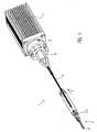
- FIG. 1 1shows a catheter device 1.
- the catheter device 1according to the invention represents a pump.
- the catheter device 1has a pump head 3 at a distal end 2.
- the pump head 3has a rotor 3.2 for conveying a medium in the conveying direction 5, which is connected to a drive shaft 4.
- the conveying direction 5is directed from the distal end 2 to a proximal end 6.
- a motor 7is arranged at the distance from the pump head 3 proximal end 6.
- the drive shaft 4is surrounded by a catheter shaft 8 and connected by a clutch 9 frictionally connected to the motor 7.
- the pump head 3comprises a butt plate 10 at the distal end, the rotor 3.2 arranged on the drive shaft 4, a pump housing 3.1 and an outflow tube 18.
- the butt plate 10is formed from a ball 10.1 with an attached cylindrical portion 10.2.
- the butt plate 10is made of stainless steel, for example ( Fig.2 . Figure 3 ).
- the butt plate 10could also be formed of polyethylene PE, polypropylene PP, polyetheretherketone PEEK, polyvinyl chloride PVC, Teflon PTFE, acrylic, epoxy, polyurethane PU, carbon fiber, coated materials, composite materials, PEBAX, a polyether block amide. In principle, all hemocompatible materials are suitable because only a small mechanical stress on this component occurs.
- the diameter of the ball 10.1is approximately 3.2 mm.
- the cylindrical portion 10.2is about 5.5 mm long and has a diameter of about 2.2 mm.
- the total length of the butt plateis about 7.0 mm.
- the cylindrical portion 10.2has at its distal end, in the connection region to the ball 10.1 a transversely to the conveying direction 5 arranged through hole 10.3. Furthermore, the cylinder 10.2 has an axial bore 10.4, which extends from the proximal end of the cylindrical portion 10.2 to the ball 10.1 out, so that a communicating passage from the through hole 10.3 is formed to the proximal end of the butt plate 10. in the The area of the axial bore 10.4 is formed a step 10.5, so that the axial bore is widened in the direction of the proximal end.
- the through hole 10.3on the one hand avoided that in the butt plate a blind hole is formed and on the other hand, the through hole allows the attachment of a thread that is helpful in compressing the pump head 3.
- the ball 10.1 of the butt plate 10may also be provided a pigtail, a spiral, a meandering wire with ball point or an atraumatic fiber bundle.
- the butt plateis preferred because of its small size.
- the tip of the butt plate 10is an atraumatic ball for the protection of the heart muscle (endocardium).
- About the butt plate 10 of the pump head 3can be supported on the heart wall.
- a tubular catheter shaft piece 8.1is inserted from the proximal end into the butt plate 10 to the step.
- the distal catheter shaft 8.1is snugly received in the axial bore 10.4 and is fixed there ( Fig. 4 ).
- the distal catheter shaft 8.1is made of polyurethane or other suitable material, in particular an elastic plastic material (eg PE, PVC, Teflon, elastomer) formed.
- the distal end of the distal catheter shaft 8.1is connected to the butt plate 10.
- the compoundcan be formed as an adhesive bond by means of, for example, cyanoacrylate adhesive or it takes place as a welded, clamped or shrink-welded connection.
- the distal catheter shaft 8.1forms a straight but slightly flexible connection between the butt plate 10 and the pump housing 3.1.
- the straight connectionestablishes a coaxiality of all components arranged in it (drive shaft, shaft protection, housing, connection socket).
- the distal catheter shaft 8.1is used in conjunction with the butt plate 10 as a positioning aid of the pump head 3 when introduced into a vessel or the heart.
- the catheter shaft 8.1 in the present embodimenthas a length of about 25 mm, an outer diameter of about 1.9 mm and an inner diameter of about 1.3 mm.
- a distal, tubular connector socket 12.1provided ( Fig. 5 . Fig. 6 ).
- the distal connection bushing 12.1has a larger inner diameter in the distal region than in the proximal region.
- the proximal end of the distal catheter shaft piece 8. 1is snugly received and fixed.
- a distal connection section 3.1.1 of the pump housing 3.1is accommodated in the proximal region of the distal connection bushing 12.1, a distal connection section 3.1.1 of the pump housing 3.1 is accommodated.
- the distal connection section 3.1.1 of the pump housing 3.1is connected to the distal connection bushing 12.1 and the proximal end of the distal catheter shaft section 8.1 (FIG. Fig. 7a, Fig. 7b ).
- the distal connection socket 12.1has a length of about 5 mm and an outer diameter of about 2.2 mm. In the distal region the diameter is approximately 2 mm and in the proximal region approximately 1.5 mm. The shorter the connection bushing, the lower the resulting stiffening.
- the distal and an analogous trained proximal connection socket 12.1, 12.2are for example made of stainless steel, copper, brass, titanium or other suitable metal, polyethylene (PE), polypropylene (PP), Teflon (PTFE), PEBAX, a polyether block Amide, or other suitable material formed.
- the expandable or compressible pump housing 3.1is a tubular grid structure 3.1.6 made of Nitinol or other suitable memory alloy or other shape memory material, such as plastic, iron alloy, copper alloy.
- the pump housing 3.1is subdivided from distal to proximal into five sections (FIG. Fig. 8 ).
- the first distal sectionis a tubular distal connection section 3.1.1.
- a second sectionis a conically expanded in the conveying direction 5 suction 3.1.2.
- the suction section 3.1.2is followed by a pump section 3.1.3.
- the tubular pump section 3.1.3receives the rotor 3.2.
- the inner diameter of the pump section 3.1.3 in the expanded stateis approximately 6.15 mm.
- An outlet section 3.1.4conically narrows in the conveying direction 5 and forms the connection between the pump section 3.1.3 and a proximal connecting section 3.1.5.
- the proximal connection section 3.1.5is analogous to the distal connection section 3.1.1 tubular with a smaller diameter than the pump section 3.1.3.
- the pump housing 3.1can be compressed so that it does not exceed a maximum diameter of less than 3 mm over the entire length.
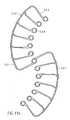
- the lattice structure 3.1.6 of the pump housing 3.1has openings 3.1.7 between the lattice struts (FIG. Fig. 8 . Fig. 9 ).
- the openingsare formed as polygons 3.1.7, in the present Embodiment diamonds are.
- small diamonds 3.1.7.1are provided in the pump section 3.1.3.
- the small diamonds 3.1.7.1are summarized step by step to become larger diamonds. Adjacent to a small rhombus is a larger rhombus with double edge length arranged. This doubling of the edge length is repeated until the openings have the desired size.
- large diamonds 3.1.7.2are provided, which have approximately four times the edge length of the small diamonds 3.1.7.1.
- the large diamonds 3.1.7.2are summarized to smaller diamonds.
- medium-sized diamonds 3.1.7.3are provided which have approximately twice the edge length of the small diamonds 3.1.7.1 ( Fig. 9 ).
- the formation of the openings 3.1.7 and the number of multiplicationscan be arbitrary.
- the width of the lattice strutsis increased.
- the strength of the lattice strutsis kept approximately equal or even amplified to the larger diamonds out.
- the lattice structure 3.1.6 of the pump housing 3.1is covered in the pump section 3.1.3 with a PU covering 3.1.8, whereby the grid openings are sealed liquid-tight.
- This covering or the sealing of the grid structure 3.1.6can also be used e.g. by a PU tube which is arranged on the surface outside or inside, be formed.
- a covering other than PUsuch as e.g. PE, PP, silicone or parylene, as long as it meets the mechanical and geometric requirements.
- the performance parameters including blood damage to the pumpcan be controlled specifically.
- proximal connection section 3.1.5 of the pump housing 3.1is received in the proximal connection socket 12.2 and connected thereto.
- proximal connection bushing 12.2a tubular proximal catheter shaft section 8.2 is accommodated analogously to the distal connection bushing 12.1 and connected thereto ( Fig. 7a, Fig. 7b ).
- Fig. 7a, Fig. 7bThe same types of connection already described above may be provided.
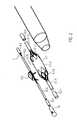
- a distal shaft protection 13.1 and a proximal shaft protection 13.2are arranged in the axial direction ( Fig. 6 ).
- the distal and the proximal shaft protection 13.1, 13.2are formed as a tube made of PU or another of the materials already listed above.
- the distal shaft protection 13.1extends in the direction of conveyance 5 from just before the distal connection bush 12.1 to the distal end of the pump section 3.1.3 of the pump housing 3.1, i. to the rotor 3.2.
- the proximal shaft protector 13.2extends from the proximal end of the rotor 3.2 to just past the proximal end of the proximal connection bushing 12.1.
- the distal and the proximal shaft protection 13.1, 13.2are in the two areas in which they are disposed within the distal and the proximal connection sleeve 12.1, 12.2 and the distal and proximal catheter shaft 8.1, 8.2, connected to these.
- connection sockets 12.1, 12.2together with the components arranged therein (shaft protection, pump housing, catheter shaft) a bearing area for the drive shaft 4.
- the connection sockets 12.1, 12.2ensure the Achszentriertheit the drive shaft 4, in particular in the pump housing 3.1.
- the drive shaft 4is arranged in the axial direction.
- the drive shaft 4has three sections in the conveying direction 5.
- the rotor 3.2.is glued to the drive shaft.
- other non-positive connectionssuch as welding or clamping can be provided.
- the proximal shaft protection 13.2( Fig. 2 . Fig.
- the distal and proximal shaft guards 13.1, 13.2center and support the drive shaft 4 during operation and during the compression and expansion process.
- the drive shaft 4is preferably formed of a plurality, in particular six wires (not shown) which are arranged left or right wound around a soul (not shown) formed.
- the outer diameter of the drive shaft 4is approximately 0.48 mm.
- the drive shaft 4can also have a different number of souls and wires and have a smaller or a larger diameter.
- the diameter of the drive shaftmay be in the range of 0.3 mm to 1 mm, and is preferably about 0.4 mm to 0.6 mm.
- the smaller the diameter of the drive shaftthe larger the rotational speed can be, because the smaller the diameter, the lower the speed with which the circumference of the drive shaft moves with respect to its surroundings.
- a high peripheral speedis problematic when the drive shaft is in contact with the environment.
- the catheter deviceis designed for speeds greater than 20,000 rpm and up to 40,000 rpm. Therefore, the diameter of the drive shaft 4 is made as small as possible, but so thick that it still has sufficient strength.
- the drive shaft 4is wound left - is in the axial direction about the distal and the proximal portion of the drive shaft 4.1, 4.3 an oppositely wound (here: dextrorotatory) spiral guide 14 arranged to the friction of the To minimize drive shaft 4, to avoid the wall contact of the drive shaft 4 with the proximal catheter shaft 8.2 and to prevent kinking of the drive shaft 4 as a result of bending.
- the guide spiral 14may be formed of stainless steel and glued to the shaft protection 13.1, 13.2. It can also be provided to form the guide spiral as a spring.
- the winding direction of the guide spiral 14may also be equal to the winding direction of the drive shaft 4.
- the drive shaft 4extends from the distal end of the distal shaft protection 13.1 in the conveying direction 5 behind the distal connection bush 12.1 up to the coupling 9.
- a bearing plate 15is arranged ( Fig. 6 ).
- the bearing plate 15is provided with a through hole 15.1.
- the diameter of the through hole 15.1corresponds approximately to the outer diameter of the drive shaft 4.
- the bearing disk 15is arranged on the drive shaft 4 such that it receives the proximal end of the distal shaft protection 13.1 and limited in the conveying direction 5.
- the bearing plate 15is formed for example of stainless steel, Teflon or ceramic or other suitable material.
- the bearing plate 15is connected by means of cyanoacrylate with the fixed shaft protection and therefore can absorb axial forces against the conveying direction 5 (connecting means s.o.).
- Fig. 11athe covering in the form of the PU skin is stretched between the comb-shaped frame structure. Due to the structure of the rotor 3.2 as a coated frame structure 3.2.1 Nitinol, it is possible to expand the rotor 3.2 or to compress.
- the PU skinhas a high elasticity, so that it is not damaged during compression.
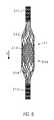
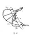
- the frame structure 3.2.1has a circumferential, helical or spiral outer boundary frame 3.2.2 with a plurality of rotor frames 3.2.3 connected to the boundary frame 3.2.2 and extending radially inward (FIG. Fig. 12 ). At the free ends of the rotor struts 3.2.3 rings 3.2.4 are formed. Through the rings 3.2.4 of the rotor struts 3.2.3, the drive shaft 4 extends.
- a spacer sleeve 16is arranged in each case.
- the distal end of the rotor 3.2rests against the bearing disk 15 with a spacer sleeve 16 at the distal end.
- the end-side spacer sleeve 16may also be formed as a special bearing spacer sleeve 16. In this way, two of the frame structures 3.2.1 form a two-bladed rotor 3.2.
- the rotor 3.2can also be one-piece ( Fig. 11b ) or have a plurality of frame structures ( Fig. 11a ). Each frame structure forms a rotor blade.
- a frame structure 3.2.1is shown for a rotor 3.2, which forms two rotor blades. If required, a plurality of rotor blades and, accordingly, a plurality of frame structures 3.2.1 can be arranged on a rotor 3.2.
- the frame structuremay also have any other suitable shape.
- the distance between two adjacent rings 3.2.4is smaller than the corresponding portion of the spiral bounding box 3.2.2.
- the slope of the rotor 3.2can be determined. It can vary within a rotor 3.2.
- the pitch of the rotor 3.2is determined.
- the length of the spacer sleeves 16can be uniform for all positions, but it can also be varied symmetrically or asymmetrically for each position. Due to the complete design freedom, a very flexible design of the rotor 3.2 can be achieved. Due to the flexible design, it is possible to generate different conveying or pumping properties of the rotor 3.2.
- the rotor 3.2has a high dimensional stability with a flexible design possibility and with minimum use of material (for example a thin frame structure). It achieves maximum rigidity and stability. Nevertheless, the combination of the frame structure with the string, which further supports the properties of the frame structure by stabilization, allows very high compression. This leads to the very good compressibility and expandability of the rotor. Due to the good surface formation of the PU skin on the lattice structure, a very good adaptation of the housing structure to the rotor structure is possible.
- the rotor 3.2has approximately the inner diameter of the compressed pump housing 3.1 in the compressed state.
- the outer diameter of the compressed pump housingis approximately between 2 mm to 4 mm, and preferably about 3.3 mm.
- the drive shaft 4is analogously received by a proximal connection socket 12.2.
- a tubular elastic discharge hose 18is arranged ( Fig. 1 . Fig. 13 ).
- the discharge hose 18is formed of PU.
- the discharge hose 18has a length of about 70 mm, a diameter of about 10 mm and a wall thickness of about 0.01 mm to 0.1 mm and preferably about 0.03 mm.
- the two ends of the outflow hose 18are formed tapered, wherein at the proximal conical end of the outflow hose, a cylindrical portion is arranged.
- the distal conically tapered end of the outflow hose 18closes tightly with the PU covering of the pump section 3.1.3 of the pump housing 3.1.
- the cylindrical proximal portionis fixedly connected to the proximal catheter shaft 8.2. Both are connected by means of dissolved PU liquid-tight.
- outlet openings 18.1are arranged radially circumferentially.
- the outlet openings 18.1may be e.g. be formed in the conveying direction 5 oval. It can also be provided that the outlet openings are round, crescent-shaped or in any geometry to generate other outlet flows.
- the outlet openings 18.1swirl the blood emerging into the bulbus aorticus. This prevents a laminar flow and thus the water jet pump effect against the coronary arteries.
- Outflow tube 18directs the pumping volume of the pump from the left ventricle via the aortic valve into the aorta.
- the outflow hose 18acts as a check valve. With a positive pressure difference between outflow hose 18 and aorta, the outflow hose 18 is more or less open according to the flow rate generated by the pump. At zero or negative pressure difference, the discharge tube 18 closes due to its high flexibility just like the aortic valve and fits tightly against the proximal catheter shaft 8.2. This flexibility results in a good seal during the flow over the sails of the aortic valve. In this way, there is only low reflux from the aorta into the left ventricle.
- the clutch 9 and the motor 7are arranged.
- the distance between the pump head 3 and the coupling 9 or the length of the proximal catheter shaft 8.2may vary depending on the patient and is approximately 90 to 150 cm.
- a tubular cover tube 29is arranged above the catheter device 1.
- the cover tube 29is designed such that it surrounds the compressed pump head 3 and the proximal catheter shaft 8.2. Through the cover tube 29 of the pump head 3 is held in its compressed state.
- the cover tube 29is withdrawn from the fixed catheter device 1 until the pump head 3 is exposed.
- Pump housing 3.1 and rotor 3.2unfold due to the spring force of the elastic material radially outward. That is, the grid structure 3.1.6 of the pump housing 3.1 and the frame structure 3.2.1 of the rotor 3.2 expand until they have reached their predetermined diameter. It may also be provided to use temperature effects of the memory material during expansion supportive.
- the cover tube 29is advanced to the shaft cap 10, whereby the rotor 3.2 and the pump housing 3.1 are compressed and drawn into the cover tube, after which it is extracted through the puncture site.
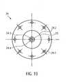
- the coupling 9is a magnetic coupling ( Fig. 14 . Fig. 15 ).
- the coupling 9has a coupling housing 19 with a distal magnet unit 23.1.
- the coupling housing 19is connected to the proximal catheter shaft 8.2, which forms a continuous cavity.
- the coupling housing 19hermetically separates the proximal catheter shaft 8.2 from a motor assembly 30.
- the motor assembly 30has a proximal magnet unit 23.2.
- the proximal magnet unit 23.2is non-positively connected to the motor 7.
- the distal magnet unit 23. 1is connected to the drive shaft 4 via a coupling element 22.
- the distal magnet unit 23.1 and the proximal magnet unit 23.2are coupled to one another in a rotationally fixed manner via magnetic forces.
- a non-positive connectionis ensured with non-contact rotary power transmission.
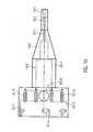
- the coupling housing 19has from distal to proximal a distal cylindrical portion 19.1, a conically widening portion 19.2, a second cylindrical portion 19.3 and a proximal cylindrical portion 19.4.
- the clutch housingis e.g. formed from polymethyl acrylate (PMMA) or another injection-moldable or machined material.
- a centrally disposed in the axial direction through holeis formed in the distal cylindrical portion 19.1 .
- the through holeextends through the entire coupling housing 19th
- the through holenarrows in three stages from a first catheter shaft receiving portion 19.5 to a second guide coil receiving portion 19.6 and to a third drive shaft passage portion 19.7.
- the bore diameter of the catheter shaft receiving portion 19.5is about 1.9 mm, that of the guide spiral receiving portion 19.6 is about 1.28 mm and that of the third bore portion is about 1.0 mm.
- the proximal end of the proximal catheter shaftis disposed in the catheter shaft receiving portion 19.5 of the clutch housing 19 and fixedly connected thereto. In the guide spiral receiving portion 19.6, the guide coil 14 is received.
- the drive shaft 4extends through the through-bore of the drive shaft passage portion 19.7 of the distal cylindrical portion 19.1 and the conically widening portion 19.1, 19.2.
- the drive shaft passage section 19.7expands in the conically widening section 19.2 into a fourth bore section 19.8.
- the fourth bore sectionmerges into a hollow cylindrical bearing section 19. 9 at the beginning of the second cylindrical section 19.
- an outer ring magnet 20.1is arranged in the distal end region of the storage section 19.9.
- the outer ring magnet 20.1is fixed via a press fit in the bore of the bearing section 19.9 and can additionally or alternatively be fixed by means of an adhesive bond.
- the storage section 19.9has a diameter of about 10 mm.
- the bore of the bearing portion 19.9merges into a larger sixth distal coupling portion 19.10.
- a radially arranged flushing bore 19.15is formed in the distal coupling section 19.10.
- a pumpfor introducing a medium, e.g. NaCl, glucose solution, Ringer's solution, plasma expander, etc. connected.
- a mediume.g. NaCl, glucose solution, Ringer's solution, plasma expander, etc. connected.
- the bore of the distal coupling portion 19.10merges into a larger proximal coupling portion 19.11.
- 19.11 formed paragraph 19.12 8 x M1.6 threaded holes 19.13 are radially symmetrical.
- At the proximal end of the proximal portion 19.4three L-shaped cutouts 19.14, distributed around the circumference, arranged.
- the distal coupling portion 19.10has a diameter of about 22 mm.
- the flushing bore 19.15has a diameter of about 6.5 mm and the proximal coupling portion 19.11 has a diameter of about 30 mm.
- the proximal end of the drive shaft 4is rotatable, tensile and pressure-resistant (non-positively) connected to a cuboid square bar 21 ( Figure 17 ).
- the square rod 21In the axial direction, the square rod 21 a recess 21.1 for receiving the proximal end of the drive shaft 4.
- the drive shaft 4is fixed in the recess.
- the square rod 21is made of brass, for example, which has good lubricating properties. Other suitable materials are all materials to be extruded or cut, such as PE, PP, PTFE, gold, silver, titanium, diamond, etc.
- the square bar 21has a length of about 19.4 mm and a cross section of about 2.88 mm x 2.88 mm.
- the square rod 21transmits the rotational movement of the motor to the drive shaft.
- the square rod 21may have any geometric shape that allows a statically determined force entry.
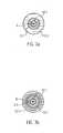
- the square rod 21is received by an axial recess 22.1 axially displaceable within a rotationally symmetrical coupling element 22 ( Fig. 23 ). As a result, it is able to compensate for differences in length in the axial direction ( Fig. 18 ).
- the recess 22.1is formed by a larger, central bore and four along the circumference of the central bore arranged smaller holes.
- the holesmay be formed by drilling, erosion, ultrasonic drilling, laser drilling or water jet drilling.
- the arrangement of the holes four axially extending double stop edgesare provided.
- the recess 22.1is arranged within a cylindrical portion 22.2 of the coupling element 22 and extends from the distal end of the coupling element 22 to just before a disc-shaped proximal portion 22.3 of the coupling element 22nd
- the cylindrical portion 22.2has an outer diameter of about 8 mm and the disc-shaped portion 22.3 has an outer diameter of about 18 mm.
- the recess 22.1is formed such that the square rod 21 is fixed radially or in the circumferential direction and is received axially displaceable.
- the radial fixation of the square bar 21is effected by the contacting of all four longitudinal edges of the square bar 21 with one of the four double stop edges of the recess 22.1. With an axial displacement of the square rod 21 in the recess 22.1 results in the corresponding lines of contact only a minimal friction.
- a square barfor example, a triangular or pentagonal bar or a profile bar with an arbitrary in the longitudinal direction of the rod constant cross-sectional area can be provided.
- the Recess 22.1is to be adapted in shape to the cross-sectional area of the profile bar.
- a shoulder 22.4is formed at the distal outer end or circumference of the cylindrical portion 22.2 of the coupling element 22 at the distal outer end or circumference of the cylindrical portion 22.2 of the coupling element 22.
- a second inner ring magnet 20.2is arranged at the distal outer end or circumference of the cylindrical portion 22.2.
- the paragraph 22.4takes the ring magnet 20.2 such that its outer surface is flush with the lateral surface of the cylindrical portion 22.2. This forms in conjunction with the 19.9 of the coupling housing 19 in the surrounding him corresponding outer ring magnet 20.1 a magnetic ring bearing 20.3.
- the two ring magnets 20.1, 20.2are arranged such that e.g. the north pole of the outer ring magnet is oriented distally and the south pole is oriented proximally.
- the north and the south pole of the inner ring magnetare formed correspondingly opposite. Accordingly, the north and south poles of the two ring magnets can also be arranged vice versa.
- the magnetic ring bearing 20.3centers the drive shaft 4 in the axial and in the radial direction. The radial centering is done by the magnetic attraction forces in the radial direction.
- the axial centeringtakes place in that with a small offset of the inner ring magnet 20.2 magnetic restoring forces are generated, which pull the inner ring magnet 20.2 in a position coinciding in the axial direction with the position of the outer ring magnet 20.1 position. At a larger offset, however, repulsion forces between the two magnetic rings 20.1 and 20.2 occur, whereby they are pressed apart.
- the ring magnets 20.1, 20.2do not touch, i. no lubrication is required.
- the magnetic ring bearingdampens vibration.
- a magnet receptacle 22.5is formed in the disk-shaped section 22.3 of the magnetic coupling element 22.
- the magnet holder 22.5is a centric circular cutout.
- the central circular cutout 22.5has a diameter of about 16.5 mm and a depth of about 3 mm.
- the magnet holder 22.5accommodates the four-segment annular distal magnet unit 23.1.
- the annular distal magnet unitis glued into the magnet holder 22.5.
- a ball head bearing mount 22.6is formed centrally.
- the ball-head bearing mount 22.6is an approximately hemispherical recess 22.6.
- the hemispherical recess 22.6has a diameter of about 0.5 to 1.3 mm.
- the square rod 21 or the cylindrical section of the coupling element 22is received by the fourth bore section 19.8 or by the bearing section 19.9 of the coupling housing 19.
- the disc-shaped portion 22.3 of the coupling element 22is received by the distal coupling portion 19.10 of the coupling housing 19.
- the clutch housing 19is hermetically separated from the engine assembly by a shroud 24 ( Fig. 19 ).
- the clutch housing 19is gas-tight and liquid-tight except for the flushing bore 19.15 in the clutch housing 22 and the free spaces between the drive shaft passage section 19.7 and the drive shaft 4.
- the cover plate 24is arranged on the shoulder 19.12 of the coupling housing 19 and is fixed by eight screws, which are received in accordance with radially symmetrically arranged in the cover plate 24 holes 24.1 and are screwed into the threaded holes 19.13 of the coupling housing 19. This compound is liquid and gas tight.
- the lens 24is formed, for example, from polymethyl acrylate (PMMA) or other non-metallic material (such as Peek, PEBAX, Teflon, PP, PE, all injection-moldable, extrudable, or chipping non-magnetic materials).
- the lens 24On the distal side, the lens 24 has a central thickening 24.2.
- a central hemispherical cutout 24.4is formed in the center of the cover plate 24 in the center of the cover plate 24 in the center of the cover plate 24 .
- a cylindrical centering pin 24.5In the through hole 24.3 a cylindrical centering pin 24.5 is fixed ( Figure 21 ).
- a ball head 24.6is arranged which is received in the hemispherical cutout ( Fig. 15 . Fig. 20 ).
- the distal magnet unit 23.1is acted upon proximally with a force. These opposite forces cause a resultant force with which the coupling element 22 is pressed against the ball head 24.6. This resulting force is adjusted so that the ball head 24.6 is stored safely and yet the wear in the ball bearing is kept low.
- the ball head 24.6forms in conjunction with the distally disposed ball head bearing mount 22.7 of the coupling element 22 a ball head bearing 25.
- the ball bearing 25is a sliding bearing. It However, other sliding bearings, such as a cone bearing or a cylinder head bearing are possible in which instead of the ball a cone or a cylinder is provided as a bearing body.
- the receptacleis adapted to the shape of the bearing body accordingly.
- the axial centering of the magnetic ring bearing 20.3takes place in that the inner ring magnet 20.2 is not located in the axial direction exactly centered in the outer ring magnet 20.1, but slightly offset to the proximal. As a result, the inner ring magnet 20.2 is acted upon distally with a force.
- the ball head 24.6may be formed of ruby, aluminum oxide or a hard plastic.
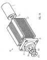
- the motor arrangementcomprises the proximal magnet unit 23.2, a proximal magnet mount 26, a coupling flange 27, a motor mount 7.1, with a cooling fan arranged thereon and the motor 7 (FIG. Fig. 14 . Fig. 22 ).
- a proximal magnet unit 23.2is arranged axially in alignment with the distal magnet unit 23.1 at a distance of approximately 0.5 to 8 mm and preferably approximately 1 to 2 mm.
- the proximal annular magnet unit 23.2has four segments analogous to the distal magnet unit 23.1.
- the magnetic receptacle 26is disc-shaped and has on its distal side a central circular cutout 26.1.
- cutout 26.1are analogous to the distal magnet unit 23.1 glued four magnet segments using two-component epoxy resin adhesive or cyanoacrylate adhesive (see above).
- the four segments of the distal and the proximal magnet unit 23.1, 23.2may be formed as bent bar magnets each having a different polarity at their end regions.
- the four segmentsmay also be formed as four quarters of a bent ring magnet.
- the segmentscan also be designed as short, axially aligned bar magnets which are arranged in a ring. It can also be provided more than four segments. In the initial position, the two magnets are arranged such that each overlap a north and a south pole of the bar magnet of the two magnet units 23.1, 23.2 and attract each other.
- the four segmentsare arranged four times alternating with their north and south poles on impact so that the segments attract a magnet unit.
- the distal and the proximal magnet unit 23.1, 23.2are arranged to one another such that complementary poles are arranged opposite each other. As a result, the two magnet units attract and it can be a torque transmitted because the magnetic forces would like to maintain this complementary pole arrangement.
- the central circular cutout 26.1has a diameter of approximately 16.5 mm and a depth of approximately 3 mm.
- the magnet holder 26is connected to a motor shaft 7.2 of the motor 7.
- the magnet holder 26is rotatably disposed within a correspondingly shaped recess of the coupling flange 27 of the motor mount.
- the magnet holder 26is rotatably disposed within a correspondingly shaped recess of the coupling flange 27 of the motor mount.
- the magnet holder 26is rotatably disposed within a correspondingly shaped recess of the coupling flange 27 of the motor mount.
- the coupling flange 27are arranged equally spaced three dowel pins 27.1.
- the clutch housing 19is connected to the dowel pins 27.1 of the coupling flange 27 of the motor assembly.
- the coupling flange 27is secured while maintaining the axis symmetry on a distal end face 7.1.1 of the motor mount.
- the motor mount 7.1is a cuboid body, are arranged on the side surfaces 7.1.2 cooling fins 7.1.3.
- the motor mount 7.1has a centrally located bore 7.1.4 in the axial direction. Through this hole 7.1.4, the motor shaft is guided 7.2. Furthermore, an axially aligned recess 7.1.5 is provided in which the motor 7 is arranged.
- the motor 7is for example a standard electric motor the company Faulhaber with a power of 38 W at 30,000 rpm or another suitable engine.
- a cooling fanis arranged on a side surface 7.1.2 of the cuboid motor mount 7.1 .
- a cover tube 29is arranged over the pump head 3 and a distal portion of the proximal catheter shaft piece.
- the cover tube 29has an inner diameter which corresponds in the region of the pump head 3 to the outer diameter of the unexpanded pump housing.
- the outer diameter of the cover tubeis approximately 3 mm.
- the two magnet units 23.1, 23.2are spatially separated from each other by the cover plate 24 in the coupling housing 19. Due to the magnetic attraction forces between the two magnet units 23.1, 23.2 there is a non-positive connection. In each case opposite poles of the two magnet units 23.1, 23.2 face each other, whereby they attract each other and a non-rotatable frictional connection is formed.
- the ball head bearing mount 22.7 of the coupling element 22is pressed onto the ball head 24.6 of the cover plate 24 and forms the ball head bearing 25.
- the ball bearingcentered the axial movement of the drive shaft. 4
- the inner ring magnet 20.1is radially guided at a constant distance in the outer ring magnet 20.2. In this way centered and leads the magnetic ring bearing 20.3 in conjunction with the ball bearing 25, the rotationally symmetrical movement of the coupling element 22 and the drive shaft 4 to prevent shocks or unbalance.
- the motor shaft 7.2rotates at a speed of about 20,000 rpm to 40,000 rpm, and preferably about 32,000 rpm to 35,000 rpm, which are transmitted to the drive shaft 4.
- the rotor 3.2delivers a delivery rate of approximately 2 l / min to 2.5 l / min at a differential pressure of 60 mm Hg.
- the resistance at the distal magnet unit 23.1increases.
- the magnetic fields between the proximal and the distal magnet unit 23.2, 23.1are not completely superimposed during operation, since the distal magnet unit 23.1 always follows the proximal magnet unit 23.2 slightly. If the required torque at the distal magnet unit 23.1 now increases, the north and south poles of the magnet units 23.1, 23.2 no longer overlap but repel each other. As a result, the distal magnet unit 23.1 is pressed distally by the proximal magnet unit 23.2. The magnetic connection between the two magnet units 23.1, 23.2 is disconnected. The drive shaft 4 stops immediately.
- the amount of the transmittable torqueis limited. As soon as the set torque is exceeded, the two magnet units 23.1, 23.2 separate. The distal magnet unit 23.1 can no longer follow the proximal magnet unit 23.2 due to the fast rotational movement, since the magnetic binding forces are no longer sufficient. As a result, the north and south poles no longer overlap and the magnet units 23.1, 23.2 repel each other. The connection of the magnet units 23.1, 23.2 is separated and limits the maximum transmissible torque. The magnet units 23.1, 23.2 are held by the magnetic ring bearing 20.3 by the mutual repulsion of the ring magnets 20.1, 20.2 in the decoupled state.
- This conditioncan be changed again by applying an external magnetic field.
- an external magnetic fieldBy means of a magnet which is guided past the coupling housing 19 from distal to proximal, the two magnet units 23.1, 23.2 can be returned to their coupled initial position.
- the coupling housing 19 and the motor assembly 30are spatially separated. This makes it possible to lubricate the drive shaft 4 via the arranged on the flushing bore 19.15 pump despite the high speed with in about 5-10 ml / h, so as to minimize the friction. It can also be provided to introduce an infusion via the flushing bore 19.15, which also lubricates the drive shaft 4.
- the small diameter of the drive shaftis at high speeds of about 32,000 rev / min of advantage.
- the peripheral speedwould be too high and it could cause damage to the drive shaft 4 and the adjacent components due to the friction.
- the drive shaft 4can transmit torque even with an axial length change (extension and shortening).
- a change in lengthoccurs, for example, when the pump head 3 is compressed.
- the rotor 3.2is compressed to the drive shaft folded and clamped in the housing.
- the pump housing 3.1extends proximally. The drive shaft 4 can move so far that it is not torn off by the rotor 3.2.
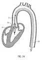
- the pump head 3is arranged in the left ventricle in such a way that the outflow tube 18 is arranged approximately centrally in the transition of the aorta to the heart, that is to say in the region of the heart valve.
- the catheter device 1is preferably designed such that it can be used to produce a specific pump pressure in the range from approximately 100 mm Hg to 150 mm Hg.
- the catheter devicedelivers blood when the pressure built up by the heart is less than the pump pressure. A sick heart is thus relieved.
- the catheter devicecan not deliver blood. In this case, the outflow tube is compressed by the heart valve, so that it is sealed. However, if the pressure difference is smaller than the pump pressure, then some blood is delivered against the pressure difference.
- Fig. 24shows the positioned catheter device 1 for left heart support.
- the pump head 3is completely in the left ventricle.
- the discharge hoseextends through the heart valve.
- a cover tube 29is first guided by means of a guide wire into the left ventricle (Seldinger technique). The guidewire is then removed from the cover tube.
- the catheter device 1is introduced with compressed and cooled pump housing 3.1 and rotor 3.2 through the cover tube until the catheter device 1 with the pump head 3 has reached the left ventricle. Unfolding occurs by retracting the cover tube 29 on the fixed catheter shaft 8 until the tip of the cover tube 29 has released the pumphead 3.
- the cover tube 29is advanced to the butt plate 10, whereby rotor 3.2 and pump housing 3.1 are retracted in the compressed state in the cover tube 29, after which it is extracted through the puncture site.
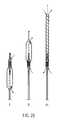
- a pumping mediumis provided from proximal to distal, that is to say pumping against the original conveying direction 5 ( Fig. 25 II).
- the bearing disk 15is arranged on the proximal side of the rotor 3.2.
- the conveying direction to the distalcan be realized either by reversing the direction of rotation with respect to the above embodiment or by reversing the pitch of the rotor 3.2.
- Outflow tube 18is located at the distal end of the pump section of pump housing 19 and extends distally beyond the pump head.
- the outflow hosecan have a lattice structure made of a shape memory material, for example similar to that of the pump housing.
- the butt plate 10extends beyond the distal end of the outflow tube.
- the pumping mediumflows through the now serving as an inlet outlet openings of the pump housing into the pump housing and passes through the now serving as an outlet inlet opening of the pump housing in the discharge hose 18.
- the embodiment just describedmay be provided, for example, for use in the right ventricle.
- the catheter device according to the inventioncan also be designed such that pumping from distal to proximal and from proximal to distal is possible ( Fig. 25 III).
- bearing washers 15are provided at the distal and proximal ends of the rotor 3.2.
- the outflow tube 18is arranged at the distal end of the pump section 3.1.3 of the pump housing 3.1 and extends in the distal direction.
- the discharge hose 18has a grid structure for stiffening, e.g. similar to the pump housing.
- the grid structureis covered with a PU skin.
- the diameter of the discharge hosecorresponds approximately to that of the expanded pump housing.
- a pumping mediumcan enter and exit through the outlet openings of the pump housing.
- the pumping mediumthen enters, for example, via the outlet openings of the pump housing and the inlet openings of the pump housing in the outflow tube and exits at the distal end of the outflow tube.
- the flow through the catheter deviceis reversed accordingly.
- the pumping mediumenters the outflow hose at the distal end of the outflow hose and passes via the inlet opening of the pump housing to the outlet openings of the pump housing.
- the embodiment just describedcan be used, for example, for drainage or for filling hollow organs or spaces.
- the reversal of the conveying directioncan be achieved on the one hand by reversing the direction of rotation of the rotor and on the other hand by reversing the pitch of the rotor.
- the magnet unitseach have four curved bar magnets, which are each set with opposite poles to each other.
- the magnet unitscan also be designed such that the north and south poles of the magnet units are aligned in the axial direction, wherein the poles are arranged on the axially distally or proximally facing surfaces.
- the magnetsare arranged annularly according to the previous embodiments.
- Such a couplingcan be used for example for driving a milling head instead of a rotor.
- a microfillere.g. Kidney stones or bone are minimally invasively milled.
- the number of magnetscan basically be varied as desired.
- the radial compressibility of the componentspermits the realization of a puncture diameter which is justifiable for percutaneous implantation in Seldinger technique, due to the very small diameter of the catheter device of about 3 mm. Due to the expansion of the rotor up to a diameter of about 15 mm, it is still possible to realize very high flow rates.
- Expansible catheter pumpseg US 4,753,221
- a propellerwith several stiff pump blades. These are arranged pivotally. Since the wings are stiff, they can not be made arbitrarily wide because they would give the catheter in the folded state, a too large thickness. Therefore, the delivery rate is limited.
- the rotor after the WO 99/44651has an elastic band to connect the ends of a Nitinol spiral with a rotation axis. Due to this elastic connection, the helix is not perfectly centered. As a result, vibrations occur during pumping which make higher speeds or delivery rates impossible.
- the rotorDue to the frame structure of the rotor with boundary frame and rotor struts according to the catheter device 1, the rotor is more stable, foldable and can be expanded to almost any size diameter.
- the pitch of the rotorcan also be varied as desired.
- the rotormay be formed with one or more rotor blades, wherein the rotor blades have correspondingly a quarter, a half, a whole or any number of wraps around the drive shaft. This means, that the rotor according to the invention is arbitrarily variable in size, its shape, its pitch and therefore can be used for a variety of applications.
Landscapes
- Health & Medical Sciences (AREA)
- Heart & Thoracic Surgery (AREA)
- Engineering & Computer Science (AREA)
- Life Sciences & Earth Sciences (AREA)
- General Health & Medical Sciences (AREA)
- Anesthesiology (AREA)
- Biomedical Technology (AREA)
- Hematology (AREA)
- Cardiology (AREA)
- Animal Behavior & Ethology (AREA)
- Mechanical Engineering (AREA)
- Public Health (AREA)
- Veterinary Medicine (AREA)
- Vascular Medicine (AREA)
- External Artificial Organs (AREA)
- Non-Portable Lighting Devices Or Systems Thereof (AREA)
- Endoscopes (AREA)
- Eye Examination Apparatus (AREA)
Abstract
Description
Translated fromGermanDie Erfindung betrifft eine Katheter-Vorrichtung, die eine miniaturisierte Pumpe ist.The invention relates to a catheter device which is a miniaturized pump.
Für die Behandlung schwer herzkranker Patienten werden zunehmend implantierbare Blutpumpen eingesetzt. Derartige Blutpumpen sind bisher vorwiegend für den langfristigen Einsatz vorgesehen. Es werden aber auch Blutpumpen entwickelt, die für die kurzfristige Herzunterstützung ausgelegt sind und minimal-invasiv eingesetzt werden können. Medizinische Ziele sind dabei die Entlastung und Gesundung des Herzens oder aber die Überbrückung bis zu einer möglichen Herztransplantation. Die Breite des Einsatzgebietes solcher Pumpen hängt einerseits von der Einfachheit der Einbringung in den Körper, andererseits von den realisierbaren technischen Eigenschaften und insbesondere der zuverlässig realisierbaren Betriebsdauer der verfügbaren Pumpensysteme ab. Idealerweise sollte eine solche Blutpumpe für die Kurzfristbehandlung perkutan-intravasal ohne jeglichen chirurgischen Eingriff einsetzbar sein.Implantable blood pumps are increasingly being used to treat patients with severe heart disease. Such blood pumps have hitherto been intended primarily for long-term use. However, blood pumps are also being developed that are designed for short-term cardiac support and can be used minimally invasively. Medical goals are the relief and recovery of the heart or the bridging up to a possible heart transplantation. The breadth of the field of application of such pumps depends on the one hand on the simplicity of the introduction into the body, on the other hand on the realizable technical properties and in particular on the reliably realizable operating time of the available pump systems. Ideally, such a short-term blood pump should be percutaneously-intravascular without any surgical intervention.
Im kardiogenen Schock ist die Auswurfleistung des linken Ventrikels erheblich reduziert. Die verminderte Koronarversorgung kann zum irreversiblen Herzversagen führen. Durch den Einsatz eines temporären linksventrikulären Unterstützungssystems soll die Pumpfunktion des linken Ventrikels teilweise bzw. weitgehend übernommen und die Koronarversorgung verbessert werden. Bei Herzoperationen kann ein solches System links- und rechtsventrikulär eingesetzt werden und eine Herz-Lungenmaschine ersetzen.In cardiogenic shock, the output of the left ventricle is significantly reduced. The reduced coronary supply can lead to irreversible heart failure. By using a temporary left ventricular assist system, the pumping function of the left ventricle should be partially or largely taken over and the coronary supply improved. In heart surgery, such a system can be used left and right ventricular and replace a heart-lung machine.
Ein perkutan-intravsal implantierbares System, das bisher klinische Bedeutung erlangt hat, ist die intraaortale Ballonpumpe (IABP). Die Intraaortale Ballonpumpe oder intraaortale Gegenpulsation ist ein mechanisches System, das auch zur Unterstützung der Pumpleistung des Herzens bei Patienten mit einem kardiogenen Schock eingesetzt wird. Dabei wird ein Katheter mit einem zylindrisch geformten Kunststoffballon über die Leiste in die Brustschlagader (Aorta thoracalis) vorgeschoben, so dass der Ballon unterhalb des Abgangs der linken Schlüsselbeinarterie (Arteria subclavia sinistra) liegt. Dort wird der Ballon mit einer externen Pumpe rhythmisch mit jeder Herzaktion in der Diastole mit 30-40 cm3 Helium aufgeblasen und in der Systole wieder abgelassen. Auf diese Weise verbessert die Ballonpumpe die Durchblutung des Herzmuskels und auch die aller anderen Organe. Die erzielbare hämodynamische Verbesserung ist jedoch nur sehr begrenzt, da aufgrund des Konstruktionsprinzips der IABP keine aktive Blutförderung stattfindet. Durch eine Gegenpulsation wird lediglich im Rhythmus des Herzschlags die Aorta unterhalb des linken Ventrikels verschlossen und somit das vom Herzen noch ausgeworfene Blut zurückgedrückt und umverteilt, damit auch in die Koronarien. Eine Steigerung des Blutflusses erfolgt nicht.A percutaneous intravascular implantable system that has been clinically important has been the intra-aortic balloon pump (IABP). The intra-aortic balloon pump or intra-aortic counter-pulsation is a mechanical system that is also used to support the pumping power of the heart in patients with cardiogenic shock. This is a catheter with a cylindrical molded plastic balloon is advanced over the groin into the thoracic aorta (aorta thoracalis) so that the balloon lies below the exit of the left clavicular artery (subclavian artery). There, the balloon is inflated rhythmically with an external pump with each heart action in diastole with 30-40 cm3 of helium and drained again in systole. In this way, the balloon pump improves the circulation of the heart muscle and also of all other organs. However, the achievable hemodynamic improvement is very limited, since due to the design principle of IABP no active blood delivery takes place. By counterpulsation, only at the rhythm of the heartbeat, the aorta below the left ventricle is closed and thus the blood ejected from the heart is pushed back and redistributed, thus also into the coronary arteries. There is no increase in blood flow.
Eine bekannte transfemoral implantierbare Mikro-Axialpumpe "Hemopump™"der Firma Medtronic Inc, USA, stellt sich nach experimenteller und vorläufiger klinischer Prüfung als erfolgsversprechendes Konzept dar, welches eine ausreichende Linksherzentlastung bewirken kann. Der Ansaugstutzen der Pumpe wird retrograd über die Aortenklappe im linken Ventrikel platziert. Der Pumpenrotor befindet sich am Ende einer Kanüle in der oberen Aorta descendens und wird durch einen externen Motor angetrieben. Nachteil des Systems ist, dass die transfemorale Implantation aufgrund des großen Durchmessers des Rotors nur operativ über eine femorale Arterietomie und gegebenenfalls durch eine Graftankopplung möglich ist.A well-known transfemoral implantable micro-axial pump "Hemopump™ " from Medtronic Inc., USA, is a promising concept after experimental and provisional clinical trials, which can provide sufficient left-sided focus. The suction port of the pump is placed retrograde over the aortic valve in the left ventricle. The pump rotor is located at the end of a cannula in the upper descending aorta and is driven by an external motor. Disadvantage of the system is that the transfemoral implantation is only possible surgically via a femoral artery and possibly by a Graftankopplung due to the large diameter of the rotor.
Aus der
In der
Aus der
In der
In der
Der vorliegenden Erfindung liegt die Aufgabe zugrunde, eine perkutan-intravasal durch die Femoralarterie einsetzbare Blutpumpe zur Herzunterstützung bereitzustellen, die ohne chirurgischen Eingriff eingeführt werden kann.It is an object of the present invention to provide a percutaneous-intravascular intravenous blood pump for cardiac assist which can be inserted without surgical intervention.
Die Aufgabe wird mit einer Katheter-Vorrichtung gemäß Anspruch 1 gelöst. Vorteilhafte Ausgestaltungen der Erfindung sind in den Unteransprüchen angegeben.The object is achieved with a catheter device according to claim 1. Advantageous embodiments of the invention are specified in the subclaims.
Die Katheter-Vorrichtung umfasst eine Antriebswelle, die mit einem Motor verbunden ist und einen Rotor, der am distalen Endbereich auf der Antriebswelle befestigt ist. Der Rotor weist eine Rahmenstruktur auf, die aus einem schraubenförmigen Begrenzungsrahmen und sich radial nach innen vom Begrenzungsrahmen erstreckenden Rotorstreben ausgebildet ist. Die Rotorstreben sind mit ihren vom Begrenzungsrahmen entfernten Enden an der Antriebswelle befestigt. Zwischen den Begrenzungsrahmen und der Antriebswelle erstreckt sich eine elastische Bespannung. Die Rahmenstruktur ist aus einem elastischen Material derart ausgebildet, dass sich der Rotor nach einer aufgezwungenen Kompression selbständig entfaltet.The catheter device includes a drive shaft connected to a motor and a rotor attached to the drive shaft at the distal end portion. The rotor has a frame structure formed of a helical restriction frame and rotor struts extending radially inwardly from the restriction frame. The rotor struts are secured to the drive shaft with their ends remote from the bounding box. Between the limiting frame and the drive shaft extends an elastic covering. The frame structure is formed of an elastic material such that the rotor unfolds automatically after an imposed compression.
Durch die Rahmenstruktur des Rotors mit Begrenzungsrahmen und Rotorstreben ist der Rotor sehr stabil, aber dennoch faltbar und lässt sich auf nahezu beliebig kleine Durchmesser komprimieren. Dadurch, dass prinzipiell eine nahezu beliebig lange Ausbildung des Rotors in Längsrichtung und Radialrichtung möglich ist, kann der Rotor je nach dem zur Verfügung stehenden Raum im Hinblick auf eine maximale Förderleistung optimiert werden. Es ist somit möglich, die Förderleistung für eine jede Anwendung optimal anzupassen.Due to the frame structure of the rotor with boundary frame and rotor struts, the rotor is very stable, yet foldable and can be compressed to almost any small diameter. Due to the fact that, in principle, an almost arbitrarily long design of the rotor in the longitudinal direction and radial direction is possible, the rotor can be optimized depending on the available space with regard to a maximum delivery capacity. It is thus possible to optimally adjust the delivery rate for each application.
Der Rotor ist derart komprimierbar, dass die Einbringung in den Körper mit einer Punktionsnadel über eine Punktion mit einem Durchmesser von in etwa 9 French (ca. 3 mm) erfolgen kann. Durch das selbständige Entfalten des Rotors wird ein Rotordurchmesser erzielt, der um ein Vielfaches größer als der Durchmesser des Rotors im komprimierten Zustand ist. Hierdurch wird eine hohe Förderleistung erzielt.The rotor is compressible such that it can be introduced into the body with a puncture needle via a puncture having a diameter of approximately 9 French. By the independent deployment of the rotor, a rotor diameter is achieved, which is many times larger than the diameter of the rotor in the compressed state. As a result, a high flow rate is achieved.
Durch den gerüstartigen Aufbau aus Begrenzungsrahmen und Rotorstreben wird dem Rotor eine hohe Festigkeit verliehen, die es erlaubt, den Rotor mit hohen Drehzahlen zu drehen, ohne dass er unwucht wird. Ein Prototyp dieser Katheter-Vorrichtung konnte über mehrere Stunden zum Fördern einer Flüssigkeit mit einer Drehzahl von etwa 32.000 U/min betrieben werden. Der Rotor wies einen Durchmesser von etwa 18 French (=ca. 6 mm) auf und war derart ausgestaltet, dass eine Druckdifferenz von etwa 120 mmHg erzielt wurde. Dies ist für eine derart miniaturisierte Pumpe eine außergewöhnliche Leistung. Mit dieser Katheter-Vorrichtung wurde auch ein deutlicher Fortschritt in Bezug auf Zuverlässigkeit und Lebensdauer erzielt.Due to the framework-like construction of the boundary frame and rotor struts, the rotor is given a high degree of rigidity, which allows the rotor to be rotated at high speeds without being unbalanced. A prototype of this catheter device could be operated for several hours to deliver a liquid at a speed of about 32,000 rpm. The rotor had a diameter of about 18 French (= about 6 mm) and was designed so that a pressure difference of about 120 mmHg was achieved. This is an extraordinary achievement for such a miniaturized pump. With this catheter device, a significant advance in reliability and durability has also been achieved.
Vorzugsweise ist die Rahmenstruktur des Rotors aus einem Formgedächtnismaterial, wie z.B. Nitinol, ausgebildet. Beim Komprimieren kann der Rotor auf eine Temperatur gebracht werden, bei der das Formgedächtnismaterial weich wird. Ein aus Nitinol bestehender Rotor wird beispielsweise bei einer Temperatur von etwa 0°C komprimiert. Beim Erwärmen wird das Formgedächtnismaterial wieder fest und entfaltet sich. In der Regel ist es nicht möglich, den Rotor ohne Abzukühlen wieder zerstörungsfrei zu komprimieren.Preferably, the frame structure of the rotor is made of a shape memory material, e.g. Nitinol, formed. During compression, the rotor can be brought to a temperature at which the shape memory material softens. For example, a rotor made of nitinol is compressed at a temperature of about 0 ° C. Upon heating, the shape memory material solidifies again and unfolds. As a rule, it is not possible to non-destructively compress the rotor again without cooling down.
Die elastische Bespannung zwischen Begrenzungsrahmen und Antriebswelle ist vorzugsweise aus einer Polymerbeschichtung, wie z.B. PU, PE, PP, Silikon oder Parylene ausgebildet.The elastic covering between the limiting frame and the drive shaft is preferably made of a polymer coating, such as e.g. PU, PE, PP, silicone or parylene formed.
Zweckmäßigerweise ist der Rotor von einem rohrförmigen Pumpenabschnitt eines Pumpengehäuses umgeben. Das Pumpengehäuse ist aus einem Gitter ausgebildet, dessen Öffnungen zumindest im Bereich des Pumpenabschnitts mittels einer elastischen Bespannung geschlossen sind. Ein solches Pumpengehäuse kann mit einem geringen Spaltabstand zum Rotor ausgebildet sein, wodurch sich optimale Strömungsbedingungen einstellen und die Förderleistung weiter optimiert werden kann.Conveniently, the rotor is surrounded by a tubular pump section of a pump housing. The pump housing is formed of a grid, the openings at least are closed in the region of the pump section by means of an elastic covering. Such a pump housing may be formed with a small gap distance from the rotor, whereby optimum flow conditions can be set and the delivery rate can be further optimized.
Das Gitter des Pumpengehäuses ist vorzugsweise aus einem Formgedächtnismaterial ausgebildet, das zusammen mit dem Rotor komprimierbar ist.The grid of the pump housing is preferably formed of a shape memory material which is compressible together with the rotor.
Durch das Pumpengehäuse wird der Rotor von äußeren Einflüssen geschützt.The pump housing protects the rotor from external influences.
Die Erfindung wird im folgenden anhand der Zeichnungen beispielhaft näher erläutert. Diese zeigen schematisch in:
- Fig. 1
- ein perspektivische Darstellung einer erfindungsgemäßen Katheter-Vorrichtung,
- Fig. 2
- eine Explosionszeichnungen einer erfindungsgemäßen Katheter-Vorrichtung ,
- Fig. 3
- eine Schaftkappe der Katheter-Vorrichtung in einer seitlich geschnittenen Ansicht,
- Fig. 4
- ein distales Katheterschaftstück der Katheter-Vorrichtung in einer seitlich geschnittenen Ansicht,
- Fig. 5
- eine Verbindungsbuchse der Katheter-Vorrichtung in einer seitlich geschnittenen Ansicht,
- Fig. 6
- eine Pumpe der Katheter-Vorrichtung mit Lagerung in einer seitlich geschnittenen Ansicht,
- Fig. 7a
- einen Schnitt entlang der Linie A-A durch die distale Verbindungsbuchse der Katheter-Vorrichtung,
- Fig. 7b
- einen Schnitt entlang der Linie B-B durch die proximale Verbindungsbuchse der Katheter-Vorrichtung,
- Fig. 8
- eine Gitterstruktur eines Pumpengehäuses der Katheter-Vorrichtung,
- Fig. 9
- einen Ausschnitt der Gitterstruktur des Pumpengehäuses der Katheter-Vorrichtung,
- Fig. 10
- eine Antriebswelle mit Führungsspirale und Wellenschutz der Katheter-Vorrichtung,
- Fig. 11a
- eine Rahmenstruktur eines Rotors einer Pumpe der Katheter-Vorrichtung,
- Fig. 11b
- eine weitere Rahmenstruktur des Rotors der Pumpe der Katheter-Vorrichtung,
- Fig. 12
- den erfindungsgemäßen Rotor der Pumpe der Katheter-Vorrichtung in einer perspektivischen Ansicht,
- Fig. 13
- einen Abströmschlauch der Katheter-Vorrichtung in einer perspektivischen Ansicht,
- Fig. 14
- eine erfindungsgemäße Kupplung mit Kupplungsgehäuse und Motor der KatheterVorrichtung in einer perspektivischen Ansicht,
- Fig. 15
- die erfindungsgemäße Kupplung mit dem Kupplungsgehäuse der KatheterVorrichtung in einer perspektivischen Ansicht,
- Fig. 16
- das Kupplungsgehäuse der Katheter-Vorrichtung in einer perspektivischen Ansicht,
- Fig. 17
- eine Vierkantstange der Kupplung der Katheter-Vorrichtung in einer seitlichen Ansicht,
- Fig. 18
- ein Kupplungselement der Kupplung der Katheter-Vorrichtung in einer seitlichen Ansicht,
- Fig. 19
- eine Abschlussscheibe der Kupplung der Katheter-Vorrichtung in einer seitlichen Ansicht,
- Fig. 20
- eine Kugelkopflagerkugel der Kupplung der Katheter-Vorrichtung in einer seitlichen Ansicht,
- Fig. 21
- einen Zentrierstift der Kupplung der Katheter-Vorrichtung in einer seitlichen Ansicht,
- Fig. 22
- eine Motoraufnahme der Katheter-Vorrichtung in einer seitlichen Ansicht,
- Fig. 23
- das Kupplungselement mit der darin angeordneten Vierkantstange in einer Draufsicht,
- Fig. 24
- die im Körper positionierte Katheter-Vorrichtung, und
- Fig. 25
- schematisch alternative Ausführungsformen der Katheter-Vorrichtung.
- Fig. 1
- a perspective view of a catheter device according to the invention,
- Fig. 2
- an exploded view of a catheter device according to the invention,
- Fig. 3
- a butt plate of the catheter device in a side view,
- Fig. 4
- a distal catheter shaft of the catheter device in a side-cut view,
- Fig. 5
- a connector socket of the catheter device in a side-cut view,
- Fig. 6
- a pump of the catheter device with storage in a side-cut view,
- Fig. 7a
- a section along the line AA through the distal connection socket of the catheter device,
- Fig. 7b
- a section along the line BB through the proximal connection socket of the catheter device,
- Fig. 8
- a lattice structure of a pump housing of the catheter device,
- Fig. 9
- a detail of the grid structure of the pump housing of the catheter device,
- Fig. 10
- a drive shaft with guide spiral and shaft protection of the catheter device,
- Fig. 11a
- a frame structure of a rotor of a pump of the catheter device,
- Fig. 11b
- another frame structure of the rotor of the pump of the catheter device,
- Fig. 12
- the rotor of the pump of the catheter device according to the invention in a perspective view,
- Fig. 13
- a discharge tube of the catheter device in a perspective view,
- Fig. 14
- 3 shows a coupling according to the invention with coupling housing and motor of the catheter device in a perspective view,
- Fig. 15
- the coupling according to the invention with the coupling housing of the catheter device in a perspective view,
- Fig. 16
- the coupling housing of the catheter device in a perspective view,
- Fig. 17
- a square bar of the coupling of the catheter device in a side view,
- Fig. 18
- a coupling element of the coupling of the catheter device in a side view,
- Fig. 19
- a cover plate of the coupling of the catheter device in a side view,
- Fig. 20
- a ball-head bearing ball of the coupling of the catheter device in a side view,
- Fig. 21
- a centering pin of the coupling of the catheter device in a side view,
- Fig. 22
- a motor mount of the catheter device in a side view,
- Fig. 23
- the coupling element with the square rod arranged therein in a plan view,
- Fig. 24
- the catheter device positioned in the body, and
- Fig. 25
- schematically alternative embodiments of the catheter device.
Der Pumpenkopf 3 weist einen Rotor 3.2 zum Fördern eines Mediums in Förderrichtung 5 auf, der mit einer Antriebswelle 4 verbunden ist. Die Förderrichtung 5 ist vom distalen Ende 2 zu einem proximalen Ende 6 gerichtet. An dem vom Pumpenkopf 3 beabstandeten proximalen Ende 6 ist ein Motor 7 angeordnet. Die Antriebswelle 4 ist von einem Katheterschaft 8 umgeben und mittels einer Kupplung 9 kraftschlüssig mit dem Motor 7 verbunden.The
Nachfolgend wird zunächst der Pumpenkopf 3 näher erläutert. Der Pumpenkopf 3 umfasst eine Schaftkappe 10 am distalen Ende, den auf der Antriebswelle 4 angeordneten Rotor 3.2, ein Pumpengehäuse 3.1 und einen Abströmschlauch 18.Subsequently, the
Die Schaftkappe 10 ist aus einer Kugel 10.1 mit einem angesetzten zylinderförmigen Abschnitt 10.2 ausgebildet. Die Schaftkappe 10 ist beispielsweise aus Edelstahl ausgebildet (
Der Durchmesser der Kugel 10.1 beträgt in etwa 3.2 mm. Der zylinderförmige Abschnitt 10.2 ist in etwa 5,5 mm lang und hat einen Durchmesser von in etwa 2,2 mm. Die Gesamtlänge der Schaftkappe beträgt in etwa 7,0 mm.The diameter of the ball 10.1 is approximately 3.2 mm. The cylindrical portion 10.2 is about 5.5 mm long and has a diameter of about 2.2 mm. The total length of the butt plate is about 7.0 mm.
Der zylinderförmige Abschnitt 10.2 weist an seinem distalen Ende, im Anschlussbereich zur Kugel 10.1 eine quer zur Förderrichtung 5 angeordnete Durchgangsbohrung 10.3 auf. Weiterhin weist der Zylinder 10.2 eine axiale Bohrung 10.4 auf, die sich vom proximalen Ende des zylinderförmigen Abschnittes 10.2 bis zur Kugel 10.1 hin erstreckt, so dass ein kommunizierender Durchgang von der Durchgangsbohrung 10.3 bis zum proximalen Ende der Schaftkappe 10 ausgebildet ist. Im Bereich der axialen Bohrung 10.4 ist eine Stufe 10.5 ausgebildet, so dass die axiale Bohrung in Richtung des proximalen Endes aufgeweitet ist.The cylindrical portion 10.2 has at its distal end, in the connection region to the ball 10.1 a transversely to the conveying
Durch die Durchgangsbohrung 10.3 wird einerseits vermieden, dass in der Schaftkappe ein Sackloch entsteht und andererseits erlaubt das Durchgangsloch die Anbringung eines Fadens, der beim Komprimieren des Pumpenkopfes 3 hilfreich ist.By the through hole 10.3 on the one hand avoided that in the butt plate a blind hole is formed and on the other hand, the through hole allows the attachment of a thread that is helpful in compressing the
Anstelle der Kugel 10.1 der Schaftkappe 10 kann auch ein Pigtail, eine Spirale, ein mäanderförmiger Draht mit Kugelspitze oder ein atraumatisches Faserbündel vorgesehen sein. Die Schaftkappe ist aufgrund ihrer geringen Größe bevorzugt.Instead of the ball 10.1 of the
Die Spitze der Schaftkappe 10 ist eine atraumatische Kugel zum Schutz des Herzmuskels (Endocard). Über die Schaftkappe 10 kann der Pumpenkopf 3 an der Herzwand abgestützt werden.The tip of the
Ein rohrförmiges bzw. schlauchförmiges, distales Katheterschaftstück 8.1 ist vom proximalen Ende in die Schaftkappe 10 bis zur Stufe eingeführt. Das distale Katheterschaftstück 8.1 wird in der axialen Bohrung 10.4 passgenau aufgenommen und ist dort fixiert (
Das distale Katheterschaftstück 8.1 bildet eine gerade, aber leicht flexible Verbindung zwischen der Schaftkappe 10 und dem Pumpengehäuse 3.1. Die gerade Verbindung stellt eine Koaxialität aller in ihr angeordneten Bauteile (Antriebswelle, Wellenschutz, Gehäuse, Verbindungsbuchse) her.The distal catheter shaft 8.1 forms a straight but slightly flexible connection between the
Das distale Katheterschaftstück 8.1 dient in Verbindung mit der Schaftkappe 10 als Positionierungshilfe des Pumpenkopfes 3 beim Einbringen in ein Gefäß bzw. das Herz.The distal catheter shaft 8.1 is used in conjunction with the
Das Katheterschaftstück 8.1 im vorliegenden Ausführungsbeispiel weist eine Länge von in etwa 25 mm, einen Außendurchmesser von in etwa 1,9 mm und einen Innendurchmesser von in etwa 1,3 mm auf.The catheter shaft 8.1 in the present embodiment has a length of about 25 mm, an outer diameter of about 1.9 mm and an inner diameter of about 1.3 mm.
Am proximalen Ende des distalen Katheterschaftstücks 8.1 ist eine distale, röhrenförmige Verbindungsbuchse 12.1 vorgesehen (
Die distale Verbindungsbuchse 12.1 weist eine Länge von in etwa 5 mm und einen Außendurchmesser von in etwa 2,2 mm auf. Im distalen Bereich beträgt der Durchmesser in etwa 2 mm und im proximalen Bereich in etwa 1,5 mm. Je kürzer die Verbindungsbuchse ist, desto geringer ist die hierdurch bewirkte Aussteifung.The distal connection socket 12.1 has a length of about 5 mm and an outer diameter of about 2.2 mm. In the distal region the diameter is approximately 2 mm and in the proximal region approximately 1.5 mm. The shorter the connection bushing, the lower the resulting stiffening.
Die distale und eine analog ausgebildete proximale Verbindungsbuchse 12.1, 12.2 sind beispielsweise aus Edelstahl, Kupfer, Messing, Titan oder einem anderen geeigneten Metall, aus Polyethylen (PE), Polypropylen (PP), Teflon (PTFE), PEBAX, einem Polyether-Block-Amid, oder einem anderen geeigneten Material ausgebildet.The distal and an analogous trained proximal connection socket 12.1, 12.2 are for example made of stainless steel, copper, brass, titanium or other suitable metal, polyethylene (PE), polypropylene (PP), Teflon (PTFE), PEBAX, a polyether block Amide, or other suitable material formed.
Das expandierbare bzw. komprimierbare Pumpengehäuse 3.1 ist eine rohrförmig ausgebildete Gitterstruktur 3.1.6 aus Nitinol oder einer anderen geeigneten Gedächtnislegierung oder einem anderen Formgedächtnismaterial, z.B. Kunststoff, Eisenlegierung, Kupferlegierung. Das Pumpengehäuse 3.1 ist von distal nach proximal in fünf Abschnitte unterteilt (
Die Gitterstruktur 3.1.6 des Pumpengehäuses 3.1 weist zwischen den Gitterstreben Öffnungen 3.1.7 auf (
Die Gitterstruktur 3.1.6 des Pumpengehäuses 3.1 ist im Pumpenabschnitt 3.1.3 mit einer PU-Bespannung 3.1.8 bespannt, wodurch die Gitteröffnungen flüssigkeitsdicht verschlossen sind.The lattice structure 3.1.6 of the pump housing 3.1 is covered in the pump section 3.1.3 with a PU covering 3.1.8, whereby the grid openings are sealed liquid-tight.
Diese Bespannung bzw. die Abdichtung der Gitterstruktur 3.1.6 kann auch z.B. durch einen PU-Schlauch der auf der Oberfläche außen oder innen angeordnet ist, ausgebildet sein.This covering or the sealing of the grid structure 3.1.6 can also be used e.g. by a PU tube which is arranged on the surface outside or inside, be formed.
Es kann auch eine andere Bespannung als PU verwendet werden, wie z.B. PE, PP, Silikon oder Parylene, solange sie die mechanischen und geometrischen Anforderungen erfüllt.It is also possible to use a covering other than PU, such as e.g. PE, PP, silicone or parylene, as long as it meets the mechanical and geometric requirements.
Durch die Auswahl einzelner Öffnungen 3.1.71, insbesondere der mittleren und größeren Öffnungen 3.1.7.3, 3.1.7.2, die nicht beschichtet werden, können die Leistungsparameter inkl. Blutschädigung der Pumpe gezielt gesteuert werden.By selecting individual openings 3.1.71, in particular the middle and larger openings 3.1.7.3, 3.1.7.2, which are not coated, the performance parameters including blood damage to the pump can be controlled specifically.
Durch die polygonale Struktur und die besondere Ausführung der PU-Bespannung ergibt sich eine annähernd runde Querschnittsform für das Pumpengehäuse 3.1. In Verbindung mit dem runden Rotor 3.2 ergeben sich dadurch sehr geringe Spalte zwischen Rotor 3.2 und Pumpengehäuse 3.1. Dies führt zu vergleichsweise niedriger Blutschädigung, niedrigen Leckströmen und einem guten Wirkungsgrad. Durch die Gitterstruktur 3.1.6 ergibt sich eine sehr gute radiale und axiale Stabilität sowie eine sehr gute axiale Komprimierbarkeit und Expandierbarkeit. Durch die spezielle Struktur kann sehr einfach eine Anpassung von Länge und Durchmesser an die Leistungsanforderungen erfolgen.Due to the polygonal structure and the special design of the PU covering results in an approximately round cross-sectional shape for the pump housing 3.1. In conjunction with the round rotor 3.2, this results in very small gaps between the rotor 3.2 and the pump housing 3.1. This leads to comparatively low blood damage, low leakage currents and good efficiency. By the lattice structure 3.1.6 results in a very good radial and axial stability and a very good axial compressibility and expandability. Due to the special structure It is very easy to adapt the length and diameter to the performance requirements.
Der proximale Verbindungsabschnitt 3.1.5 des Pumpengehäuses 3.1 ist in der proximalen Verbindungsbuchse 12.2 aufgenommen und mit dieser verbunden. In der proximalen Verbindungsbuchse 12.2 ist analog zur distalen Verbindungsbuchse 12.1 ein schlauchförmiges proximales Katheterschaftstück 8.2 aufgenommen und mit dieser verbunden (
Innerhalb des distalen und des proximalen Katheterschaftstückes 8.1, 8.2 ist in axialer Richtung ein distaler Wellenschutz 13.1 und ein proximaler Wellenschutz 13.2 angeordnet (
Der distale Wellenschutz 13.1 erstreckt sich in Förderichtung 5 von kurz vor der distalen Verbindungsbuchse 12.1 bis zum distalen Ende des Pumpenabschnitts 3.1.3 des Pumpengehäuses 3.1, d.h. bis zum Rotor 3.2. Der proximale Wellenschutz 13.2 erstreckt sich vom proximalen Ende des Rotors 3.2 bis kurz hinter das proximale Ende der proximalen Verbindungsbuchse 12.1.The distal shaft protection 13.1 extends in the direction of
Der distale und der proximale Wellenschutz 13.1, 13.2 sind in den beiden Bereichen, in denen sie innerhalb der distalen und der proximalen Verbindungsbuchse 12.1, 12.2 bzw. des distalen und des proximalen Katheterschaftstücks 8.1, 8.2 angeordnet sind, mit diesen verbunden.The distal and the proximal shaft protection 13.1, 13.2 are in the two areas in which they are disposed within the distal and the proximal connection sleeve 12.1, 12.2 and the distal and proximal catheter shaft 8.1, 8.2, connected to these.
Die beiden Verbindungsbuchsen 12.1, 12.2 bilden zusammen mit den darin angeordneten Bauteilen (Wellenschutz, Pumpengehäuse, Katheterschaft) einen Lagerbereich für die Antriebswelle 4. Die Verbindungsbuchsen 12.1, 12.2 gewährleisten die Achszentriertheit der Antriebswelle 4 insbesondere im Pumpengehäuse 3.1.The two connection sockets 12.1, 12.2 together with the components arranged therein (shaft protection, pump housing, catheter shaft) a bearing area for the
Innerhalb des distalen und des proximalen Wellenschutzes 13.1, 13.2 bzw. des Pumpengehäuses 3.1 ist in axialer Richtung die Antriebswelle 4 angeordnet. Die Antriebswelle 4 weist in Förderichtung 5 drei Abschnitte auf. Einen distalen Abschnitt der Antriebswelle 4.1 im Bereich der Schaftkappe 10. Einen Pumpenabschnitt der Antriebswelle 4.2, auf dem der Rotor 3.2 drehfest angeordnet ist und einen proximalen Abschnitt der Antriebswelle 4.3, der sich vom Pumpenabschnitt 3.1.3 bis hin zur Kupplung 9 erstreckt. Der Rotor 3.2. ist mit der Antriebswelle verklebt. Es können jedoch auch andere kraftschlüssige Verbindungen wie Schweißen oder Klemmen vorgesehen sein. Der proximale Wellenschutz 13.2 (
Die Antriebswelle 4 ist bevorzugt aus mehreren, insbesondere sechs Drähten (nicht dargestellt), die links- oder rechtsgewickelt um eine Seele (nicht dargestellt) angeordnet sind, ausgebildet. Der Außendurchmesser der Antriebswelle 4 beträgt in etwa 0,48 mm. Die Antriebswelle 4 kann aber auch eine andere Anzahl von Seelen und Drähten aufweisen und einen kleineren oder einen größeren Durchmesser aufweisen. Der Durchmesser der Antriebswelle kann im Bereich von 0,3 mm bis 1 mm liegen und beträgt vorzugsweise etwa 0,4 mm bis 0,6 mm. Je kleiner der Durchmesser der Antriebswelle ist, desto größer kann die Drehgeschwindigkeit sein, denn je kleiner der Durchmesser ist, desto geringer ist die Geschwindigkeit, mit der sich der Umfang der Antriebswelle gegenüber seiner Umgebung bewegt. Eine hohe Umfangsgeschwindigkeit ist problematisch, wenn die Antriebswelle mit der Umgebung in Berührung kommt. Die Katheter-Vorrichtung ist für Drehzahlen von mehr als 20.000 U/min und bis zu 40.000 U/min ausgelegt. Daher wird der Durchmesser der Antriebswelle 4 so gering wie möglich ausgebildet, aber so dick, dass sie noch eine ausreichende Festigkeit besitzt.The
Entgegen der Wickelrichtung der Antriebswelle 4 - im vorliegenden Ausführungsbeispiel ist sie links gewickelt - ist in axialer Richtung um den distalen und den proximalen Abschnitt der Antriebswelle 4.1, 4.3 ein entgegengesetzt gewickelte (hier: rechtsdrehend), spiralförmig ausgebildete Führungsspirale 14 angeordnet, um die Reibung der Antriebswelle 4 zu minimieren, den Wandkontakt der Antriebswelle 4 mit dem proximalen Katheterschaftstück 8.2 zu vermeiden sowie ein Abknicken der Antriebswelle 4 in Folge von Biegung zu verhindern. Durch die Führungsspirale 14 wird die Antriebswelle 4 geführt und geschient bzw. stabilisiert (
Die Antriebswelle 4 erstreckt sich vom distalen Ende des distalen Wellenschutzes 13.1 in Förderrichtung 5 hinter der distalen Verbindungsbuchse 12.1 bis hin zur Kupplung 9.The
Das proximale Katheterschaftstück 8.2 stellt in Verbindung mit der Führungsspirale 14 eine längen- und verwindungskonstante Verbindung zwischen dem Pumpenkopf 3 und der Kupplung 9 bereit.The proximal catheter shaft 8.2 in conjunction with the guide coil 14 a length and torsion constant connection between the
Am proximalen Ende des distalen Wellenschutzes 13.1 ist eine Lagerscheibe 15 angeordnet (
Die Lagerscheibe 15 ist beispielsweise aus Edelstahl, Teflon oder Keramik bzw. einem anderen geeigneten Material ausgebildet. Die Lagerscheibe 15 ist mittels Cyanacrylatkleber mit dem feststehenden Wellenschutz verbunden und kann daher Axialkräfte entgegen der Förderichtung 5 aufnehmen (Verbindungsmittel s.o.).The bearing
Im Pumpenabschnitt 4.2 der Antriebswelle 4 ist der spiralförmige, expandierbare Rotor 3.2 drehfest auf der Antriebswelle 4 angeordnet. Als Rotor 3.2 ist im vorliegenden Ausführungsbeispiel eine zweiflügelige, kammförmig ausgebildete Rahmenstruktur 3.2.1 aus Nitinol oder einem anderen Formgedächtnismaterial, z.B. Kunststoff (s.o.) vorgesehen, die mit einer PU-Haut beschichtet bzw. von dieser flüssigkeitsdicht umgeben ist (
Die Rahmenstruktur 3.2.1 weist einen umlaufenden, schraubenförmigen bzw. spiralförmigen äußeren Begrenzungsrahmen 3.2.2 mit mehreren mit dem Begrenzungsrahmen 3.2.2 verbundenen und radial nach innen verlaufenden Rotorstreben 3.2.3 auf (
Zwischen zwei benachbarten Ringen 3.2.4 ist jeweils eine Abstandshülse 16 angeordnet. Das distale Ende des Rotors 3.2 liegt mit einer distal endseitigen Abstandshülse 16 an der Lagerscheibe 15 an. Die endseitige Abstandshülse 16 kann auch als spezielle Lagerabstandshülse 16 ausgebildet sein. Auf diese Weise bilden zwei der Rahmenstrukturen 3.2.1 einen zweiflügeligen Rotor 3.2 aus.Between two adjacent rings 3.2.4 a
Der Rotor 3.2 kann auch einteilig (
Der Abstand zwischen zwei benachbarten Ringen 3.2.4 ist kleiner als der entsprechende Abschnitt des spiralförmigen Begrenzungsrahmens 3.2.2. Je größer die Differenz zwischen dem Abstand zwischen zwei Ringen 3.2.4 und dem entsprechenden Abschnitt des spiralförmigen Begrenzungsrahmens 3.2.2 ist, desto größer ist die Steigung des Rotors. Durch die Länge der Abstandshülsen 16 kann somit die Steigung des Rotors 3.2 festgelegt werden. Sie kann innerhalb eines Rotors 3.2 variieren.The distance between two adjacent rings 3.2.4 is smaller than the corresponding portion of the spiral bounding box 3.2.2. The greater the difference between the distance between two rings 3.2.4 and the corresponding portion of the spiral bounding frame 3.2.2, the greater the pitch of the rotor. By the length of the
Durch die Länge bzw. Anzahl der Abstandshülsen 16 im Verhältnis zur Dimensionierung des umlaufenden, spiralförmigen äußeren Begrenzungsrahmens 3.2.2 zwischen zwei Rotorstreben 3.2.3 wird die Steigung des Rotors 3.2 festgelegt. Die Länge der Abstandshülsen 16 kann für alle Positionen einheitlich sein, sie kann aber auch symmetrisch oder asymmetrisch für jede Position variiert werden. Durch die völlige Gestaltungsfreiheit kann ein sehr flexibles Design des Rotors 3.2 erreicht werden. Durch das flexible Design ist es möglich, unterschiedliche Förder- bzw. Pumpeigenschaften des Rotors 3.2 zu generieren.By the length or number of
Der Rotor 3.2 weist eine hohe Formstabilität bei flexibler Gestaltungsmöglichkeit und bei minimalem Materialeinsatz (z.B. dünne Rahmenstruktur) auf. Es wird eine maximale Steifigkeit und Stabilität erreicht. Trotzdem erlaubt die Kombination aus der Rahmenstruktur mit der Bespannung, die die Eigenschaften der Rahmenstruktur durch Stabilisierung weiter unterstützt, eine sehr starke Komprimierung. Dies führt zu der sehr guten Komprimierbarkeit und Expandierbarkeit des Rotors. Aufgrund der guten Flächenausbildung der PU-Haut auf der Gitterstruktur ist eine sehr gute Anpassung der Gehäusestruktur an die Rotorstruktur möglich.The rotor 3.2 has a high dimensional stability with a flexible design possibility and with minimum use of material (for example a thin frame structure). It achieves maximum rigidity and stability. Nevertheless, the combination of the frame structure with the string, which further supports the properties of the frame structure by stabilization, allows very high compression. This leads to the very good compressibility and expandability of the rotor. Due to the good surface formation of the PU skin on the lattice structure, a very good adaptation of the housing structure to the rotor structure is possible.
Der Rotor 3.2 weist im komprimierten Zustand in etwa den Innendurchmesser des komprimierten Pumpengehäuses 3.1 auf. Der Außendurchmesser des komprimierten Pumpengehäuses beträgt in etwa zwischen 2 mm bis 4 mm und vorzugsweise in etwa 3,3 mm.The rotor 3.2 has approximately the inner diameter of the compressed pump housing 3.1 in the compressed state. The outer diameter of the compressed pump housing is approximately between 2 mm to 4 mm, and preferably about 3.3 mm.
Im expandierten Zustand ist der spiralförmige äußere Begrenzungsrahmen 3.2.2 des Rotors 3.2 geringfügig beabstandet zur Innenfläche des Pumpengehäuses 3.1. Der Abstand zwischen dem äußeren Begrenzungsrahmen 3.2.2 und der Innenfläche des Pumpengehäuses 3.1 beträgt in etwa zwischen 0,01 mm und 0,5 mm. Je kleiner der Abstand zwischen der Rahmenstruktur 3.2.1 und der Innenfläche des Pumpengehäuses 3.1 ist, desto höher ist die Förderleistung des Rotors 3.2.In the expanded state of the spiral outer boundary frame 3.2.2 of the rotor 3.2 is slightly spaced from the inner surface of the pump housing 3.1. The distance between the outer boundary frame 3.2.2 and the inner surface of the pump housing 3.1 is approximately between 0.01 mm and 0.5 mm. The smaller the distance between the frame structure 3.2.1 and the inner surface of the pump housing 3.1, the higher the delivery rate of the rotor 3.2.
An der distal endseitigen Abstandshülse 16 des Rotors berühren sich die am distalen Wellenschutz 13.1 befestigte Lagerscheibe 15 und die distal endseitige Abstandshülse 16, die beide auf der Antriebswelle 4 angeordnet sind. Indem der Rotor 3.2 durch die Antriebswelle 4 in eine Drehbewegung versetzt wird, kontaktiert die distale Abstandshülse 16 des Rotors 3.2 die Lagerscheibe 15 in Art eines Gleitlagers. Auf diese Weise ist ein distales Rotorlager 17 ausgebildet (
Beim Pumpen wird der Rotor 3.2 aufgrund der Förderung des Pumpmediums mit einer axialen Kraft entgegen der Förderrichtung 5 belastet. Diese Kraft wird über die distal endseitige Abstandshülse 16 auf die Lagerscheibe 15 abgeleitet.When pumping the rotor 3.2 is charged due to the promotion of the pumping medium with an axial force against the conveying
Zum Schmieren des distalen Rotorlagers wird über die Durchgangsbohrung 10.3 der Schaftkappe 10, den Freiräumen zwischen dem distalen Wellenschutz 13.1 und der Antriebswelle 4 und dem Freiraum zwischen der Antriebswelle und der Lagerscheibe 15 Blut bzw. Serum eingesogen. Die Sogwirkung entsteht aufgrund der Drehbewegung der Antriebswelle 4 und des Rotors 3.2.For lubricating the distal rotor bearing, blood or serum is drawn in through the
An der proximal endseitigen Abstandshülse 16 des Rotors 3.2 wird die Antriebswelle 4 analog von einer proximalen Verbindungsbuchse 12.2 aufgenommen.At the proximal end-
In etwa am proximalen Ende des Pumpenabschnitts 3.1.3 des Pumpengehäuses ist ein rohrförmiger elastischer Abströmschlauch 18 angeordnet (
Das distale konisch zulaufende Ende des Abströmschlauches 18 schließt dicht mit der PU-Bespannung des Pumpenabschnittes 3.1.3 des Pumpengehäuses 3.1 ab. Der zylinderförmige proximale Abschnitt ist fest mit dem proximalen Katheterschaftstück 8.2 verbunden. Beide sind mittels gelöstem PU miteinander flüssigkeitsdicht verbunden.The distal conically tapered end of the
Am proximalen Ende des Abströmschlauches 18 sind radial umlaufend mehrere Auslassöffnungen 18.1 angeordnet. Die Auslassöffnungen 18.1 können z.B. in Förderrichtung 5 oval ausgebildet sein. Es kann auch vorgesehen sein die Auslassöffnungen rund, halbmondförmig bzw. in einer beliebigen Geometrie auszubilden um andere Auslassströmungen zu generieren. Die Auslassöffnungen 18.1 verwirbeln das in den Bulbus Aorticus austretende Blut. Dadurch wird eine laminare Strömung und damit der Wasserstrahlpumpeneffekt gegenüber den Koronararterien verhindert.At the proximal end of the discharge hose 18 a plurality of outlet openings 18.1 are arranged radially circumferentially. The outlet openings 18.1 may be e.g. be formed in the conveying
Der Abströmschlauch 18 leitet das Pumpvolumen der Pumpe aus dem linken Ventrikel über die Aortenklappe in die Aorta. Hierbei wirkt der Abströmschlauch 18 wie ein Rückschlagventil. Bei positiver Druckdifferenz zwischen Abströmschlauch 18 und Aorta ist der Abströmschlauch 18 entsprechend der von der Pumpe erzeugten Durchflussmenge mehr oder weniger geöffnet. Bei Null oder negativer Druckdifferenz schließt sich der Abströmschlauch 18 aufgrund seiner hohen Flexibilität genau wie die Aortenklappe und legt sich eng an das proximale Katheterschaftstück 8.2 an. Diese Flexibilität führt zu einer guten Abdichtung während der Durchströmung gegenüber den Segeln der Aortenklappe. Auf diese Weise kommt es lediglich zu geringen Rückflüssen aus der Aorta in den linken Ventrikel.
Am proximalen Ende des Katheterschaftes 8.2 sind die Kupplung 9 und der Motor 7 angeordnet. Der Abstand zwischen dem Pumpenkopf 3 und der Kupplung 9 bzw. die Länge des proximalen Katheterschaftstücks 8.2 kann je nach Patient variieren und beträgt in etwa 90 bis 150 cm.At the proximal end of the catheter shaft 8.2, the
Nachfolgend wird das Verfahren zum Expandieren des Rotors 3.2 beschrieben.Hereinafter, the method for expanding the rotor 3.2 will be described.
Über der Katheter-Vorrichtung 1 ist ein rohrförmiger Deckschlauch 29 angeordnet. Der Deckschlauch 29 ist derart ausgebildet, dass er den komprimierten Pumpenkopf 3 sowie das proximale Katheterschaftstück 8.2 umgibt. Durch den Deckschlauch 29 wird der Pumpenkopf 3 in seinem komprimierten Zustand gehalten.Above the catheter device 1, a
Nach der korrekten Positionierung des Pumpenkopfes 3 wird der Deckschlauch 29 von der fixierten Katheter-Vorrichtung 1 zurückgezogen, bis der Pumpenkopf 3 frei liegt. Pumpengehäuse 3.1 und Rotor 3.2 entfalten sich aufgrund der Federkraft des elastischen Materials radial nach außen. Das heißt, die Gitterstruktur 3.1.6 des Pumpengehäuses 3.1 und die Rahmenstruktur 3.2.1 des Rotors 3.2 weiten sich auf bis sie ihren vorgegebenen Durchmesser erreicht haben. Es kann auch vorgesehen sein Temperatureffekte des Memory-Materials beim Expandieren unterstützend zu nutzen.After the correct positioning of the
Zur Entfernung der Katheter-Vorrichtung 1 wird der Deckschlauch 29 bis zur Schaftkappe 10 vorgeschoben, wodurch der Rotor 3.2 und das Pumpengehäuse 3.1 komprimiert werden und in den Deckschlauch eingezogen werden, wonach dieser durch die Punktionsstelle hindurch extrahiert wird.To remove the catheter device 1, the
Nachfolgend werden die Kupplung 9 und der Motor 7 erläutert.Hereinafter, the
Die Kupplung 9 ist eine Magnetkupplung (
Die distale Magneteinheit 23.1 und die proximale Magneteinheit 23.2 sind über Magnetkräfte drehfest miteinander gekoppelt. Durch die beiden Magneteinheiten 23.1, 23.2 wird eine kraftschlüssige Verbindung bei berührungsfreier rotatorischer Kraftübertragung gewährleistet.The distal magnet unit 23.1 and the proximal magnet unit 23.2 are coupled to one another in a rotationally fixed manner via magnetic forces. By the two magnet units 23.1, 23.2 a non-positive connection is ensured with non-contact rotary power transmission.
Das Kupplungsgehäuse 19 weist von distal nach proximal einen distalen zylinderförmigen Abschnitt 19.1, einen sich konisch aufweitenden Abschnitt 19.2, einen zweiten zylinderförmigen Abschnitt 19.3 und einen proximalen zylinderförmigen Abschnitt 19.4 auf. Das Kupplungsgehäuse ist z.B. aus Polymethylacrylat (PMMA) ausgebildet oder einem anderen spritzgussfähigen oder zu spanenden Material hergestellt.The coupling housing 19 has from distal to proximal a distal cylindrical portion 19.1, a conically widening portion 19.2, a second cylindrical portion 19.3 and a proximal cylindrical portion 19.4. The clutch housing is e.g. formed from polymethyl acrylate (PMMA) or another injection-moldable or machined material.
Im distalen zylinderförmigen Abschnitt 19.1 ist eine in axialer Richtung mittig angeordnete Durchgangsbohrung ausgebildet. Die Durchgangsbohrung erstreckt sich durch das gesamte Kupplungsgehäuse 19.In the distal cylindrical portion 19.1 a centrally disposed in the axial direction through hole is formed. The through hole extends through the entire coupling housing 19th
Vom distalen Ende des distalen zylinderförmigen Abschnitts 19.1 verengt sich die Durchgangsbohrung dreistufig von einem ersten Katheterschaftaufnahmeabschnitt 19.5 auf einen zweiten Führungsspiraleaufnahmeabschnitt 19.6 und auf einen dritten Antriebswellendurchtrittsabschnitt 19.7.From the distal end of the distal cylindrical portion 19.1, the through hole narrows in three stages from a first catheter shaft receiving portion 19.5 to a second guide coil receiving portion 19.6 and to a third drive shaft passage portion 19.7.
Der Bohrungsdurchmesser des Katheterschaftaufnahmeabschnitts 19.5 beträgt in etwa 1,9 mm, der des Führungsspiraleaufnahmeabschnitts 19.6 in etwa 1,28 mm und der des dritten Bohrungsabschnitts in etwa 1,0 mm.The bore diameter of the catheter shaft receiving portion 19.5 is about 1.9 mm, that of the guide spiral receiving portion 19.6 is about 1.28 mm and that of the third bore portion is about 1.0 mm.
Das proximale Ende des proximalen Katheterschaftes ist im Katheterschaftaufnahmeabschnitt 19.5 des Kupplungsgehäuses 19 angeordnet und mit diesem fest verbunden. Im Führungsspiraleaufnahmeabschnitt 19.6 ist die Führungsspirale 14 aufgenommen.The proximal end of the proximal catheter shaft is disposed in the catheter shaft receiving portion 19.5 of the clutch housing 19 and fixedly connected thereto. In the guide spiral receiving portion 19.6, the
Die Antriebswelle 4 erstreckt sich durch die Durchgangsbohrung des Antriebswellendurchtrittsabschnitts 19.7 des distalen zylinderförmigen Abschnitts 19.1 und des sich konisch aufweitenden Abschnitts 19.1, 19.2. Der Antriebswellendurchtrittsabschnitt 19.7 weitet sich im sich konisch aufweitenden Abschnitt 19.2 in einen vierten Bohrungsabschnitt 19.8 auf.The
Der vierte Bohrungsabschnitt geht zu Beginn des zweiten zylinderförmigen Abschnitts 19.3 in einen hohlzylindrischen Lagerungsabschnitt 19.9 über. Im distalen Endbereich des Lagerungsabschnitts 19.9 ist ein äußerer Ringmagnet 20.1 angeordnet. Der äußere Ringmagnet 20.1 ist über eine Presspassung in der Bohrung des Lagerungsabschnitts 19.9 fixiert und kann zusätzlich oder alternativ mittels einer Klebung fixiert sein.The fourth bore section merges into a hollow cylindrical bearing section 19. 9 at the beginning of the second cylindrical section 19. In the distal end region of the storage section 19.9 an outer ring magnet 20.1 is arranged. The outer ring magnet 20.1 is fixed via a press fit in the bore of the bearing section 19.9 and can additionally or alternatively be fixed by means of an adhesive bond.
Der Lagerungsabschnitt 19.9 weist einen Durchmesser von in etwa 10 mm auf.The storage section 19.9 has a diameter of about 10 mm.
Am Anfang des proximalen zylinderförmigen Abschnitts 19.4 des Kupplungsgehäuses 19 geht die Bohrung des Lagerungsabschnitts 19.9 in einen größeren sechsten distalen Kupplungsabschnitt 19.10 über. Im distalen Kupplungsabschnitt 19.10 ist eine radial angeordnete Spülbohrung 19.15 ausgebildet.At the beginning of the proximal cylindrical portion 19.4 of the coupling housing 19, the bore of the bearing portion 19.9 merges into a larger sixth distal coupling portion 19.10. In the distal coupling section 19.10, a radially arranged flushing bore 19.15 is formed.
An der Spülbohrung ist eine Pumpe (nicht dargestellt) zum Einbringen eines Mediums, z.B. NaCl, Glukoselösung, Ringerlösung, Plasmaexpander, etc. angeschlossen.At the flushing bore is a pump (not shown) for introducing a medium, e.g. NaCl, glucose solution, Ringer's solution, plasma expander, etc. connected.
Die Bohrung des distalen Kupplungsabschnitts 19.10 geht in einen größeren proximalen Kupplungsabschnitt 19.11 über. Im zwischen dem distalen und dem proximalen Kupplungsabschnitt 19.10, 19.11 ausgebildeten Absatz 19.12 sind radial symmetrisch 8 x M 1,6 Gewindebohrungen 19.13 ausgebildet. Am proximalen Ende des proximalen Abschnitts 19.4 sind drei L-förmige Ausfräsungen 19.14, auf den Umfang verteilt, angeordnet.The bore of the distal coupling portion 19.10 merges into a larger proximal coupling portion 19.11. In between the distal and the proximal coupling portion 19.10, 19.11 formed paragraph 19.12 8 x M 1.6 threaded holes 19.13 are radially symmetrical. At the proximal end of the proximal portion 19.4 three L-shaped cutouts 19.14, distributed around the circumference, arranged.
Der distale Kupplungsabschnitt 19.10 weist einen Durchmesser von in etwa 22 mm auf. Die Spülbohrung 19.15 weist einen Durchmesser von in etwa 6,5 mm auf und der proximale Kupplungsabschnitt 19.11 weist einen Durchmesser von in etwa 30 mm auf.The distal coupling portion 19.10 has a diameter of about 22 mm. The flushing bore 19.15 has a diameter of about 6.5 mm and the proximal coupling portion 19.11 has a diameter of about 30 mm.
Das proximale Ende der Antriebswelle 4 ist dreh, zug- und druckfest (kraftschlüssig) mit einer quaderförmigen Vierkantstange 21 verbunden (
Die Vierkantstange 21 weist eine Länge von in etwa 19,4 mm und einen Querschnitt von in etwa 2,88 mm x 2,88 mm auf.The
Die Vierkantstange 21 überträgt die Drehbewegung des Motors auf die Antriebswelle. Die Vierkantstange 21 kann jede beliebige geometrische Form aufweisen, die einen statisch bestimmten Krafteintrag ermöglicht.The
Die Vierkantstange 21 wird von einer axialen Ausnehmung 22.1 innerhalb eines rotationssymmetrischen Kupplungselements 22 axial verschiebbar aufgenommen (
Durch die Anordnung der Bohrungen werden vier axial verlaufende Doppelanschlagkanten bereitgestellt. Die Ausnehmung 22.1 ist innerhalb eines zylinderförmigen Abschnitts 22.2 des Kupplungselements 22 angeordnet und erstreckt sich vom distalen Ende des Kupplungselements 22 bis kurz vor einen scheibenförmigen proximalen Abschnitt 22.3 des Kupplungselements 22.The arrangement of the holes four axially extending double stop edges are provided. The recess 22.1 is arranged within a cylindrical portion 22.2 of the
Der zylinderförmige Abschnitt 22.2 weist einen Außendurchmesser von in etwa 8 mm auf und der scheibenförmige Abschnitt 22.3 weist einen Außendurchmesser von in etwa 18 mm auf.The cylindrical portion 22.2 has an outer diameter of about 8 mm and the disc-shaped portion 22.3 has an outer diameter of about 18 mm.
Die Ausnehmung 22.1 ist derart ausgebildet, dass die Vierkantstange 21 radial bzw. in Umfangsrichtung fixiert und axial verschieblich aufgenommen wird. Die radiale Fixierung der Vierkantstange 21 erfolgt durch die Kontaktierung aller vier Längskanten der Vierkantstange 21 mit jeweils einer der vier Doppelanschlagkanten der Ausnehmung 22.1. Bei einer axialen Verschiebung der Vierkantstange 21 in der Ausnehmung 22.1 ergibt sich an den entsprechenden Berührungslinien nur eine minimale Reibung.The recess 22.1 is formed such that the
Es können auch mehr oder weniger Anschlagkanten vorgesehen sein. Anstelle einer Vierkantstange kann z.B auch eine Dreikant- oder Fünfkantstange oder eine Profilstange mit einer an sich beliebigen in Längsrichtung der Stange gleich bleibender Querschnittsfläche vorgesehen sein. Die Ausnehmung 22.1 ist in der Form entsprechend an die Querschnittsfläche der Profilstange anzupassen.It can also be provided more or less stop edges. Instead of a square bar, for example, a triangular or pentagonal bar or a profile bar with an arbitrary in the longitudinal direction of the rod constant cross-sectional area can be provided. The Recess 22.1 is to be adapted in shape to the cross-sectional area of the profile bar.
Am distalen äußeren Ende bzw. Umfang des zylinderförmigen Abschnitts 22.2 des Kupplungselements 22 ist ein Absatz 22.4 ausgebildet. Auf diesem Absatz 22.4 ist ein zweiter innerer Ringmagnet 20.2 angeordnet. Der Absatz 22.4 nimmt den Ringmagneten 20.2 derart auf, dass dessen Außenfläche bündig mit der Mantelfläche des zylinderförmigen Abschnittes 22.2 abschließt. Dieser bildet in Verbindung mit dem im Lagerungsabschnitt 19.9 des Kupplungsgehäuses 19 entsprechend ihn umgebenden äußeren Ringmagneten 20.1 ein Magnetringlager 20.3 aus.At the distal outer end or circumference of the cylindrical portion 22.2 of the
Im Magnetringlager 20.3 sind die beiden Ringmagnete 20.1, 20.2 derart angeordnet, dass z.B. der Nordpol des äußeren Ringmagnet nach distal und der Südpol nach proximal ausgerichtet ist. Der Nord- und der Südpol des inneren Ringmagneten sind entsprechend entgegengesetzt ausgebildet. Entsprechend können die Nord- und Südpole der beiden Ringmagneten auch umgekehrt angeordnet sein. Das Magnetringlager 20.3 zentriert die Antriebswelle 4 in axialer und in radialer Richtung. Die radiale Zentrierung erfolgt durch die magnetischen Anziehungskräfte in radialer Richtung. Die axiale Zentrierung erfolgt dadurch, dass bei einem kleinen Versatz des inneren Ringmagneten 20.2 magnetische Rückstellkräfte erzeugt werden, die den inneren Ringmagneten 20.2 in eine in Axialrichtung mit der Position des äußeren Ringmagneten 20.1 übereinstimmende Stellung ziehen. Bei einem größeren Versatz treten hingegen Abstoßungskräfte zwischen den beiden Magnetringen 20.1 und 20.2 auf, wodurch sie auseinander gedrückt werden.In the magnetic ring bearing 20.3, the two ring magnets 20.1, 20.2 are arranged such that e.g. the north pole of the outer ring magnet is oriented distally and the south pole is oriented proximally. The north and the south pole of the inner ring magnet are formed correspondingly opposite. Accordingly, the north and south poles of the two ring magnets can also be arranged vice versa. The magnetic ring bearing 20.3 centers the
Im Magnetringlager 20.3 berühren sich die Ringmagneten 20.1, 20.2 nicht, d.h. es ist keine Schmierung erforderlich. Zudem wirkt das Magnetringlager schwingungsdämpfend.In the magnetic ring bearing 20.3, the ring magnets 20.1, 20.2 do not touch, i. no lubrication is required. In addition, the magnetic ring bearing dampens vibration.
Am proximalen Ende des Kupplungselements ist im scheibenförmigen Abschnitt 22.3 des Magnetkupplungselements 22 eine Magnetaufnahme 22.5 ausgebildet. Die Magnetaufnahme 22.5 ist eine zentrische zirkuläre Ausfräsung.At the proximal end of the coupling element, a magnet receptacle 22.5 is formed in the disk-shaped section 22.3 of the
Die zentrische zirkuläre Ausfräsung 22.5 weist einen Durchmesser von in etwa 16,5 mm und eine Tiefe von in etwa 3 mm auf.The central circular cutout 22.5 has a diameter of about 16.5 mm and a depth of about 3 mm.
Die Magnetaufnahme 22.5 nimmt die aus vier Segmenten bestehende ringförmige distale Magneteinheit 23.1 auf. Die ringförmige distale Magneteinheit ist in die Magnetaufnahme 22.5 eingeklebt. In der proximalen Stirnseite des Kupplungselements 22 ist mittig eine Kugelkopflageraufnahme 22.6 ausgebildet. Die Kugelkopflageraufnahme 22.6 ist eine etwa halbkugelförmige Ausnehmung 22.6.The magnet holder 22.5 accommodates the four-segment annular distal magnet unit 23.1. The annular distal magnet unit is glued into the magnet holder 22.5. In the proximal end face of the
Die halbkugelförmige Ausnehmung 22.6 weist einen Durchmesser von in etwa 0,5 bis 1,3 mm auf.The hemispherical recess 22.6 has a diameter of about 0.5 to 1.3 mm.
Die Vierkantstange 21 bzw. der zylinderförmige Abschnitt des Kupplungselements 22 wird vom vierten Bohrungsabschnitt 19.8 bzw. vom Lagerungsabschnitt 19.9 des Kupplungsgehäuses 19 aufgenommen. Der scheibenförmige Abschnitt 22.3 des Kupplungselements 22 wird vom distalen Kupplungsabschnitt 19.10 des Kupplungsgehäuses 19 aufgenommen.The
Das Kupplungsgehäuse 19 wird durch eine Abschlussscheibe 24 hermetisch von der Motoranordnung getrennt (
Die Abschlussscheibe 24 ist auf dem Absatz 19.12 des Kupplungsgehäuses 19 angeordnet und ist mittels acht Schrauben fixiert, die entsprechend von radiär symmetrisch in der Abschlussscheibe 24 angeordneten Bohrungen 24.1 aufgenommen sind und in den Gewindebohrungen 19.13 des Kupplungsgehäuses 19 verschraubt sind. Diese Verbindung ist flüssigkeits- und gasdicht ausgebildet. Die Abschlussscheibe 24 ist beispielsweise aus Polymethylacrylat (PMMA) oder einem anderen nicht metallischen Material (wie z.B. Peek, PEBAX, Teflon, PP, PE, alle spritzgießbaren, extrudierbaren oder zu spanenden, nicht-magnetischen Materialien) ausgebildet.The
Distalseitig weist die Abschlussscheibe 24 eine zentrale Verdickung 24.2 auf. Im Zentrum der Abschlussscheibe 24 ist eine Durchgangsbohrung 24.3 und eine zentrische halbkugelige Ausfräsung 24.4 ausgebildet. In der Durchgangsbohrung 24.3 ist ein zylinderförmiger Zentrierstift 24.5 fixiert (
Die distale Magneteinheit 23.1 wird nach proximal mit einer Kraft beaufschlagt. Diese entgegengesetzten Kräfte bewirken eine resultierende Kraft, mit der das Kupplungselement 22 gegen den Kugelkopf 24.6 gedrückt wird. Diese resultierende Kraft wird so eingestellt, dass der Kugelkopf 24.6 sicher gelagert ist und dennoch der Verschleiß im Kugelkopflager gering gehalten wird.The distal magnet unit 23.1 is acted upon proximally with a force. These opposite forces cause a resultant force with which the
Der Kugelkopf 24.6 bildet in Verbindung mit der distal angeordneten Kugelkopflageraufnahme 22.7 des Kupplungselements 22 ein Kugelkopflager 25 aus. Das Kugelkopflager 25 ist ein Gleitlager. Es sind jedoch auch andere Gleitlager, wie z.B. ein Kegelkopflager bzw. ein Zylinderkopflager möglich, bei welchen an Stelle der Kugel ein Kegel bzw. ein Zylinder als Lagerkörper vorgesehen ist. Die Aufnahme ist der Form des Lagerkörpers entsprechend angepasst.The ball head 24.6 forms in conjunction with the distally disposed ball head bearing mount 22.7 of the coupling element 22 a ball head bearing 25. The
Das Kugelkopflager 25 stellt in Verbindung mit dem Magnetringlager 20.3 eine axiale Laufzentrierung und -führung des Kupplungselements 22 und der darin angeordneten Antriebswelle 4 innerhalb des Kupplungsgehäuses 19 sicher.The ball-and-
Die axiale Zentrierung des Magnetringlagers 20.3 erfolgt dadurch, dass der innere Ringmagnet 20.2 in Axialrichtung nicht genau mittig im äußeren Ringmagneten 20.1 angeordnet ist, sondern leicht nach proximal versetzt ist. Dadurch wird der innere Ringmagnet 20.2 nach distal mit einer Kraft beaufschlagt. Der Kugelkopf 24.6 kann aus Rubin, Aluminiumoxid oder einem harten Kunststoff ausgebildet sein.The axial centering of the magnetic ring bearing 20.3 takes place in that the inner ring magnet 20.2 is not located in the axial direction exactly centered in the outer ring magnet 20.1, but slightly offset to the proximal. As a result, the inner ring magnet 20.2 is acted upon distally with a force. The ball head 24.6 may be formed of ruby, aluminum oxide or a hard plastic.
Um zu verhindern, dass Blut und Serum durch die Freiräume zwischen der Antriebswelle 4 und dem proximalen Rotorlager 17.2, aufgrund der Rotationsbewegung der Antriebswelle 4, angesaugt werden und das Blut gerinnt und/oder an der Antriebswelle 4 anhaftet, wird über die Spülbohrung im Kupplungsgehäuse ein Spülmedium eingebracht um einen Gegendruck zum angesaugten bzw. hineingedrückten Blutstrom zu erzeugen. Dadurch wird das Kugelkopflager geschmiert. Geeignete Spülmedien sind z.B.:
- 3-20% Glukoselösung;
- 5-40% Dextranlösung mit Molmasse 5.000 bis 65.000, insbesondere 10% Dextranlösung MM 40.000 in 0,9% NaCl;
- Ringerlösung: eine Elektrolytgemischlösung mit K, Na, Mg;
- andere physiologische Elektrolytlösungen.
- 3-20% glucose solution;
- 5-40% dextran solution with molecular weight 5,000 to 65,000, in particular 10% dextran solution MM 40,000 in 0.9% NaCl;
- Ringer's solution: a mixed electrolyte solution with K, Na, Mg;
- other physiological electrolyte solutions.
Die Motoranordnung umfasst die proximale Magneteinheit 23.2, eine proximale Magnetaufnahme 26, einen Kupplungsflansch 27, eine Motoraufnahme 7.1, mit einem darauf angeordneten Kühllüfter und den Motor 7 (
Auf der proximalen Seite der Abschlussscheibe 24 ist in einem Abstand von in etwa 0,5 bis 8 mm und vorzugsweise etwa 1 bis 2 mm eine proximale Magneteinheit 23.2 axial fluchtend zur distalen Magneteinheit 23.1 angeordnet. Die proximale ringförmige Magneteinheit 23.2 weist analog zur distalen Magneteinheit 23.1 vier Segmente auf.On the proximal side of the
Die Magnetaufnahme 26 ist scheibenförmig ausgebildet und weist auf ihrer distalen Seite eine zentrische zirkuläre Ausfräsung 26.1 auf. In die Ausfräsung 26.1 sind analog zur distalen Magneteinheit 23.1 vier Magnetsegmente mittels Zwei-Komponenten-Epoxydharzkleber oder Cyanacrylatkleber eingeklebt (s.o.).The
Die vier Segmente der distalen und der proximalen Magneteinheit 23.1, 23.2 können als gebogene Stabmagneten ausgebildet sein die an ihren Endbereichen jeweils eine unterschiedliche Polung aufweisen. Die vier Segmente können auch als vier Viertel eines gebogenen Ringmagneten ausgebildet sein. Die Segmente können auch als kurze, axial ausgerichtete Stabmagnete ausgebildet sein, die ringförmig angeordnet sind. Es können auch mehr als vier Segmente vorgesehen sein. In der Ausgangstellung sind die beiden Magneten derart angeordnet, dass sich jeweils ein Nord- und ein Südpol der Stabmagneten der beiden Magneteinheiten 23.1, 23.2 überlagern und sich gegenseitig anziehen.The four segments of the distal and the proximal magnet unit 23.1, 23.2 may be formed as bent bar magnets each having a different polarity at their end regions. The four segments may also be formed as four quarters of a bent ring magnet. The segments can also be designed as short, axially aligned bar magnets which are arranged in a ring. It can also be provided more than four segments. In the initial position, the two magnets are arranged such that each overlap a north and a south pole of the bar magnet of the two magnet units 23.1, 23.2 and attract each other.
Die vier Segmente sind viermal mit ihren Nord- und Südpolen alternierend auf Stoß angeordnet, so dass sich die Segmente einer Magneteinheit anziehen. Die distale und der proximale Magneteinheit 23.1, 23.2 sind zueinander derart angeordnet, dass jeweils komplementäre Pole zueinander gegenüberliegend angeordnet sind. Hierdurch ziehen sich die beiden Magneteinheiten an und es lässt sich ein Drehmoment übertragen, da die Magnetkräfte diese komplementäre Polanordnung beibehalten möchte.The four segments are arranged four times alternating with their north and south poles on impact so that the segments attract a magnet unit. The distal and the proximal magnet unit 23.1, 23.2 are arranged to one another such that complementary poles are arranged opposite each other. As a result, the two magnet units attract and it can be a torque transmitted because the magnetic forces would like to maintain this complementary pole arrangement.
Die zentrische zirkuläre Ausfräsung 26.1 weist einen Durchmesser von in etwa 16,5 mm und eine Tiefe von in etwa 3 mm auf.The central circular cutout 26.1 has a diameter of approximately 16.5 mm and a depth of approximately 3 mm.
Die Magnetaufnahme 26 ist mit einer Motorwelle 7.2 des Motors 7 verbunden. Die Magnetaufnahme 26 ist drehbar innerhalb einer entsprechend ausgeformten Aussparung des Kupplungsflansches 27 der Motoraufnahme angeordnet. Entlang des äußeren Umfangs des ringförmigen Steges der Aussparung sind gleichmäßig beabstandet drei Passstifte 27.1 angeordnet.The
Über die L-förmigen Ausfräsungen 19.14 des Kupplungsgehäuses 19 wird das Kupplungsgehäuse 19 mit den Passstiften 27.1 des Kupplungsflansches 27 der Motoranordnung verbunden.About the L-shaped cutouts 19.14 of the clutch housing 19, the clutch housing 19 is connected to the dowel pins 27.1 of the
Der Kupplungsflansch 27 ist unter Wahrung der Achssymmetrie auf einer distalen Stirnseite 7.1.1 der Motoraufnahme befestigt. Die Motoraufnahme 7.1 ist ein quaderförmiger Körper, an dessen Seitenflächen 7.1.2 Kühllamellen 7.1.3 angeordnet sind.The
Die Motoraufnahme 7.1 weist in axialer Richtung eine mittig angeordnete Bohrung 7.1.4 auf. Durch diese Bohrung 7.1.4 ist die Motorwelle 7.2 geführt. Weiterhin ist eine axial fluchtende Ausnehmung 7.1.5 vorgesehen in der der Motor 7 angeordnet ist. Der Motor 7 ist beispielsweise ein Standard-Elektromotor der Firma Faulhaber mit einer Leistung von 38 W bei 30000 U/min oder ein anderer geeigneter Motor.The motor mount 7.1 has a centrally located bore 7.1.4 in the axial direction. Through this hole 7.1.4, the motor shaft is guided 7.2. Furthermore, an axially aligned recess 7.1.5 is provided in which the
An einer Seitenfläche 7.1.2 der quaderförmigen Motoraufnahme 7.1 ist ein Kühlungslüfter angeordnet.On a side surface 7.1.2 of the cuboid motor mount 7.1 a cooling fan is arranged.
Über dem Pumpenkopf 3 und einem distalen Bereich des proximalen Katheterschaftstücks ist ein Deckschlauch 29 angeordnet. Der Deckschlauch 29 weist einen Innendurchmesser auf, der im Bereich des Pumpenkopfes 3 dem Außendurchmesser des nicht expandierten Pumpengehäuses entspricht. Der Außendurchmesser des Deckschlauches beträgt in etwa 3 mm.Over the
Nachfolgend wird das Verfahren zum Kuppeln mit der Magnetkupplung 9 beschrieben.Hereinafter, the method for coupling with the
Die beiden Magneteinheiten 23.1, 23.2 sind durch die Abschlussscheibe 24 im Kupplungsgehäuse 19 räumlich voneinander getrennt. Durch die magnetischen Anziehungskräfte zwischen den beiden Magneteinheiten 23.1, 23.2 erfolgt eine kraftschlüssige Verbindung. Hierbei stehen sich jeweils entgegengesetzte Pole der beiden Magneteinheiten 23.1, 23.2 gegenüber, wodurch sie sich anziehen und ein drehfester Kraftschluss gebildet wird.The two magnet units 23.1, 23.2 are spatially separated from each other by the
Weiterhin wird hierdurch die Kugelkopflageraufnahme 22.7 des Kupplungselements 22 auf den Kugelkopf 24.6 der Abschlussscheibe 24 gepresst und bildet das Kugelkopflager 25 aus. Das Kugelkopflager zentriert den axialen Lauf der Antriebswelle 4.Furthermore, as a result, the ball head bearing mount 22.7 of the
Durch die Anordnung der beiden Ringmagnete 20.1, 20.2 des Magnetringlagers 20.3 wird der innere Ringmagnet 20.1 mit konstantem Abstand im äußeren Ringmagneten 20.2 radial geführt. Auf diese Weise zentriert und führt das Magnetringlager 20.3 in Verbindung mit dem Kugelkopflager 25 den rotationssymmetrischen Lauf des Kupplungselements 22 bzw. der Antriebswelle 4, um Schläge bzw. eine Unwucht zu verhindern.Due to the arrangement of the two ring magnets 20.1, 20.2 of the magnetic ring bearing 20.3, the inner ring magnet 20.1 is radially guided at a constant distance in the outer ring magnet 20.2. In this way centered and leads the magnetic ring bearing 20.3 in conjunction with the
Über die kraftschlüssige Verbindung zwischen den Magneteinheiten 23.1, 23.2 wird die vom Motor 7 über die Motorwelle 7.2 auf die proximale Magneteinheit 23.2 übertragene Drehbewegung auf die distale Magneteinheit 23.1 überführt.About the non-positive connection between the magnet units 23.1, 23.2 is transferred from the
Die Motorwelle 7.2 dreht sich mit einer Drehzahl von in etwa 20000 U/min bis 40000 U/min und vorzugsweise etwa 32000 U/min bis 35000 U/min, die auf die Antriebswelle 4 übertragen werden. Bei 32000 U/min ergibt sich eine Förderleistung des Rotors 3.2 von in etwa 2 I/min bis 2,5 I/min bei einem Differenzdruck von 60 mm Hg.The motor shaft 7.2 rotates at a speed of about 20,000 rpm to 40,000 rpm, and preferably about 32,000 rpm to 35,000 rpm, which are transmitted to the
Im Falle einer Blockierung des Rotors 3.2 muss die kraftschlüssige Verbindung zwischen Motor 7 und Antriebswelle 4 getrennt werden, um ein "Aufwickeln" der Antriebswelle 4 bei feststehendem Rotor zu verhindern. Durch ein "Aufwickeln" der Antriebswelle 4 könnte der Pumpenkopf 3 seine Position verändern und könnte dadurch das Herz und/oder die Aorta bzw. die Vene beschädigen.In the case of a blocking of the rotor 3.2, the non-positive connection between the
Sobald der Rotor 3.2 blockiert, verdreht bzw. verkürzt sich die Antriebswelle 4, der Widerstand an der distalen Magneteinheit 23.1 steigt. Die Magnetfelder zwischen der proximalen und der distalen Magneteinheit 23.2, 23.1 überlagern sich im Betrieb nicht vollständig, da die distale Magneteinheit 23.1 der proximalen Magneteinheit 23.2 immer ein wenig nachläuft. Erhöht sich nun das benötigte Drehmoment an der distalen Magneteinheit 23.1 überlagern sich die Nord- und Südpole der Magneteinheiten 23.1, 23.2 nicht mehr sondern stoßen einander ab. Hierdurch wird die distale Magneteinheit 23.1 von der proximalen Magneteinheit 23.2 in Richtung distal gedrückt. Die magnetische Verbindung zwischen den beiden Magneteinheiten 23.1, 23.2 ist getrennt. Die Antriebswelle 4 steht sofort still.As soon as the rotor 3.2 blocks, the
Durch die Verschiebung des Kupplungselements 22 in Richtung distal wird der innere Ringmagnet 20.2 des Kupplungselements 22 ebenfalls in Richtung distal verschoben und die Nord- und Südpole der beiden Ringmagneten 20.1, 20.2 des Magnetringlagers 20.3 überlagern sich nicht mehr, sondern stoßen sich ab. Hierdurch wird die Kupplung 9 im entkoppelten Zustand gehalten und es kommt zu einer dauerhaften Entkopplung von Motor 7 und Antriebswelle 4.By the displacement of the
Durch das Magnetringlager 20.3 bzw. die magnetische Verbindung der beiden Magneteinheiten 23.1, 23.2 wird der Betrag des übertragbaren Drehmoments begrenzt. Sobald das eingestellte Drehmoment überschritten wird, trennen sich die beiden Magneteinheiten 23.1, 23.2. Die distale Magneteinheit 23.1 kann der proximalen Magneteinheit 23.2 aufgrund der schnellen Drehbewegung nicht mehr nachlaufen, da die magnetischen Bindungskräfte nicht mehr ausreichen. Hierdurch überlagern sich die Nord- und Südpole nicht mehr und die Magneteinheiten 23.1, 23.2 stoßen sich ab. Die Verbindung der Magneteinheiten 23.1, 23.2 wird getrennt und das maximal übertragbare Drehmoment begrenzt. Die Magneteinheiten 23.1, 23.2 werden vom Magnetringlager 20.3 durch die gegenseitige Abstoßung der Ringmagnete 20.1, 20.2 im entkoppelten Zustand gehalten.By the magnetic ring bearing 20.3 or the magnetic connection of the two magnet units 23.1, 23.2, the amount of the transmittable torque is limited. As soon as the set torque is exceeded, the two magnet units 23.1, 23.2 separate. The distal magnet unit 23.1 can no longer follow the proximal magnet unit 23.2 due to the fast rotational movement, since the magnetic binding forces are no longer sufficient. As a result, the north and south poles no longer overlap and the magnet units 23.1, 23.2 repel each other. The connection of the magnet units 23.1, 23.2 is separated and limits the maximum transmissible torque. The magnet units 23.1, 23.2 are held by the magnetic ring bearing 20.3 by the mutual repulsion of the ring magnets 20.1, 20.2 in the decoupled state.
Dieser Zustand lässt sich durch das Ansetzen eines äußeren Magnetfelds wieder ändern. Durch einen von distal nach proximal am Kupplungsgehäuse 19 vorbeigeführten Magneten können die beiden Magneteinheiten 23.1, 23.2 wieder in ihre gekoppelte Ausgangsstellung gebracht werden. Erfindungsgemäß sind das Kupplungsgehäuse 19 und die Motoranordnung 30 räumlich voneinander getrennt. Hierdurch ist es möglich, die Antriebswelle 4 über die an der Spülbohrung 19.15 angeordnete Pumpe trotz der hohen Drehzahl mit in etwa 5-10 ml/h zu schmieren um so die Reibung zu minimieren. Es kann auch vorgesehen sein eine Infusion über die Spülbohrung 19.15 einzubringen, die die Antriebswelle 4 ebenfalls schmiert.This condition can be changed again by applying an external magnetic field. By means of a magnet which is guided past the coupling housing 19 from distal to proximal, the two magnet units 23.1, 23.2 can be returned to their coupled initial position. According to the coupling housing 19 and the
Der kleine Durchmesser der Antriebswelle ist bei hohen Drehzahlen von in etwa 32000 U/min von Vorteil. Bei größeren Durchmessern würde die Umfangsgeschwindigkeit zu hoch werden und es könnte aufgrund der Reibung zu einer Beschädigung der Antriebswelle 4 bzw. der daran angrenzenden Bauteile kommen.The small diameter of the drive shaft is at high speeds of about 32,000 rev / min of advantage. For larger diameters, the peripheral speed would be too high and it could cause damage to the
Aufgrund der räumlichen Trennung durch die Abschlussscheibe 24 ist es möglich, die Antriebswelle 4 zu schmieren bzw. abzudichten. Kein bekanntes Lager, durch das eine Welle hindurchgeführt ist, würde bei dieser Größe und derartigen Drehzahlen dicht bleiben und einen einwandfreien Lauf ermöglichen.Due to the spatial separation through the
Aus der Anordnung des Kugelkopflagers 25 (Gleitlager), des Magnetringlagers 20.3 (berührungsfrei, dämpfend und zentrierend) und des axialen Gleitlagers zwischen Antriebswelle 4 und Kupplungsgehäuse 19 ergeben sich drei Stabilisationspunkte. Dadurch kann die Antriebswelle 4 ein Drehmoment auch bei einer axialen Längenveränderung übertragen (Verlängerung und Verkürzung). Zu einer Längenänderung kommt es beispielsweise, wenn der Pumpenkopf 3 komprimiert wird. Dabei wird der Rotor 3.2 zusammengedrückt, um die Antriebswelle gefaltet und im Gehäuse festgeklemmt. Das Pumpengehäuse 3.1 verlängert sich proximal. Die Antriebswelle 4 kann sich soweit bewegen, dass sie nicht vom Rotor 3.2 abgerissen wird. Durch die Verschiebbarkeit der Antriebswelle 4 kann die Längenänderung des PU-Katheterschafts aufgrund von Flüssigkeitsaufnahme, Temperaturunterschieden, und durch Biegung des Katheterschaftes 8.2, die die Längenverhältnisse zwischen Antriebswelle 4 und Katheterschaft 8.2 beeinflussen, ausgeglichen werden. Dieser Mechanismus ist durch die Verschiebbarkeit der Vierkantstange 21 innerhalb der axialen Ausnehmung 22.1 möglich.From the arrangement of the ball bearing 25 (plain bearings), the magnetic ring bearing 20.3 (non-contact, damping and centering) and the axial sliding bearing between the
Der Pumpenkopf 3 wird derart in der linken Herzkammer angeordnet, dass der Abströmschlauch 18 in etwa mittig im Übergang der Aorta zum Herzen, also im Bereich der Herzklappe angeordnet ist. Die Katheter-Vorrichtung 1 ist vorzugsweise derart ausgebildet, dass mit ihr ein bestimmter Pumpendruck im Bereich von etwa 100 mm Hg bis 150 mm Hg erzeigt werden kann. Befindet sich das Herz in der Systole, dann fördert die Katheter-Vorrichtung Blut, wenn der vom Herz aufgebaute Druck kleiner als der Pumpendruck ist. Ein krankes Herz wird somit entlastet. Während der Diastole liegt eine entgegengesetzte Druckdifferenz vor. Ist die Druckdifferenz größer als der Pumpendruck, dann kann die Katheter-Vorrichtung kein Blut fördern. Hierbei wird der Abströmschlauch von der Herzklappe zusammengedrückt, so dass er abgedichtet ist. Ist die Druckdifferenz jedoch kleiner als der Pumpendruck, dann wird etwas Blut entgegen der Druckdifferenz gefördert.The
Zum Einbringen der Katheter-Vorrichtung wird zunächst ein Deckschlauch 29 mittels eines Führungsdrahtes bis in die linke Herzkammer geführt (Seldinger-Technik). Der Führungsdraht wird dann aus dem Deckschlauch entfernt. Die Katheter-Vorrichtung 1 wird mit komprimierten und gekühlten Pumpengehäuse 3.1 und Rotor 3.2 durch den Deckschlauch eingeführt, bis die Katheter-Vorrichtung 1 mit dem Pumpenkopf 3 die linke Herzkammer erreicht hat. Die Entfaltung erfolgt, indem der Deckschlauch 29 auf dem fixierten Katheterschaft 8 zurückgezogen wird, bis die Spitze des Deckschlauchs 29 den Pumpenkopf freigegeben 3 hat.To insert the catheter device, a
Zur Entfernung des Systems wird der Deckschlauch 29 bis zur Schaftkappe 10 vorgeschoben, wodurch Rotor 3.2 und Pumpengehäuse 3.1 im komprimierten Zustand in den Deckschlauch 29 eingezogen werden, wonach dieser durch die Punktionsstelle hindurch extrahiert wird.To remove the system, the
In einem weiteren Ausführungsbeispiel der vorliegenden Erfindung ist vorgesehen ein Pumpmedium von proximal nach distal, das heißt entgegen der ursprünglichen Förderrichtung 5 zu pumpen (
Beim Betrieb strömt das Pumpmedium durch die nun als Einlass dienende Auslassöffnungen des Pumpengehäuses ins Pumpengehäuse und gelangt über die nun als Auslass dienende Einlassöffnung des Pumpengehäuses in den Abströmschlauch 18. Über das distale Ende des Abströmschlauchs tritt das Pumpmedium aus der Katheter-Vorrichtung 1 aus.During operation, the pumping medium flows through the now serving as an inlet outlet openings of the pump housing into the pump housing and passes through the now serving as an outlet inlet opening of the pump housing in the
Das eben beschriebene Ausführungsbeispiel kann zum Beispiel für den Einsatz im rechten Ventrikel vorgesehen sein.The embodiment just described may be provided, for example, for use in the right ventricle.
In einem weiteren Ausführungsbeispiel kann die erfindungsgemäße Katheter-Vorrichtung auch derart ausgebildet sein, dass ein Pumpen von distal nach proximal und von proximal nach distal möglich ist (
Bei diesem Ausführungsbeispiel sind Lagerscheiben 15 am distalen und am proximalen Ende des Rotors 3.2 vorgesehen. Der Abströmschlauch 18 ist am distalen Ende des Pumpenabschnittes 3.1.3 des Pumpengehäuses 3.1 angeordnet und erstreckt sich in distaler Richtung. Der Abströmschlauch 18 weist zur Aussteifung eine Gitterstruktur, z.B. ähnlich dem Pumpengehäuse auf. Die Gitterstruktur ist mit einer PU-Haut bespannt. Der Durchmesser des Abströmschlauchs entspricht in etwa dem des expandierten Pumpengehäuses.In this embodiment, bearing
Beim Betrieb kann ein Pumpmedium durch die Auslassöffnungen des Pumpengehäuses ein- bzw. austreten. Das Pumpmedium tritt dann beispielsweise über die Auslassöffnungen des Pumpengehäuses und die Einlassöffnungen des Pumpengehäuses in den Abströmschlauch und tritt am distalen Ende des Abströmschlauchs aus. Bei umgekehrter Pumprichtung erfolgt die Durchströmung der Katheter-Vorrichtung entsprechend umgekehrt. Das heißt, dass das Pumpmedium am distalen Ende des Abströmschlauchs in den Abströmschlauch eintritt und über die Einlassöffnung des Pumpengehäuses zu den Auslassöffnungen des Pumpengehäuses gelangt. Somit ist durch den druck- und sogstabilisierten Abströmschlauch 18 ein Abströmen nach distal oder proximal möglich.During operation, a pumping medium can enter and exit through the outlet openings of the pump housing. The pumping medium then enters, for example, via the outlet openings of the pump housing and the inlet openings of the pump housing in the outflow tube and exits at the distal end of the outflow tube. In the reverse pumping direction, the flow through the catheter device is reversed accordingly. This means that the pumping medium enters the outflow hose at the distal end of the outflow hose and passes via the inlet opening of the pump housing to the outlet openings of the pump housing. Thus, by the pressure and suction stabilized
Das eben beschriebene Ausführungsbeispiel kann beispielsweise für Drainagen oder zum Auffüllen von Hohlorganen bzw. -räumen verwendet werden.The embodiment just described can be used, for example, for drainage or for filling hollow organs or spaces.
Die Umkehr der Förderrichtung kann einerseits durch Umkehren der Drehrichtung des Rotors und andererseits durch Umkehrung der Steigung des Rotors erzielt werden.The reversal of the conveying direction can be achieved on the one hand by reversing the direction of rotation of the rotor and on the other hand by reversing the pitch of the rotor.
Die Erfindung ist oben anhand eines Ausführungsbeispiels beschrieben, bei dem die Magneteinheiten jeweils vier gebogene Stabmagnete aufweisen, die jeweils mit entgegengesetzten Polen aneinander gesetzt sind. Im Rahmen der Erfindung können die Magneteinheiten auch derart ausgebildet sein, dass die Nord- und Südpole der Magneteinheiten in axialer Richtung ausgerichtet sind, wobei die Pole an den axial nach distal bzw. proximal weisenden Flächen angeordnet sind. Die Magnete sind entsprechend den vorherigen Ausführungsbeispielen ringförmig angeordnet. Durch eine derartige Ausrichtung der Nord- und Südpole der Magnete ziehen sich die beiden Magneteinheiten mit höheren Magnetkräften an. Dadurch ist möglich, ein höheres Drehmoment über die Kupplung zu übertragen.The invention is described above with reference to an embodiment in which the magnet units each have four curved bar magnets, which are each set with opposite poles to each other. In the context of the invention, the magnet units can also be designed such that the north and south poles of the magnet units are aligned in the axial direction, wherein the poles are arranged on the axially distally or proximally facing surfaces. The magnets are arranged annularly according to the previous embodiments. By such an orientation of the north and south poles of the magnets, the two magnet units attract with higher magnetic forces. This makes it possible to transmit a higher torque via the clutch.
Eine derartige Kupplung kann beispielsweise zum Antreiben eines Fräskopfs anstelle eines Rotors verwendet werden. Mit einer solchen Mikrofräse können z.B. Nierensteine oder Knochen minimalinvasiv gefräst werden.Such a coupling can be used for example for driving a milling head instead of a rotor. With such a microfiller, e.g. Kidney stones or bone are minimally invasively milled.
Die Anzahl der Magnete kann grundsätzlich beliebig variiert werden.The number of magnets can basically be varied as desired.
Die radiale Komprimierbarkeit der Komponenten erlaubt die Realisierung eines für eine perkutane Implantation in Seldinger-Technik vertretbar kleinen Punktionsdurchmessers, aufgrund des sehr geringen Durchmessers der Katheter-Vorrichtung von etwa 3 mm. Durch die Expansion des Rotors bis zu einem Durchmesser von in etwa 15 mm ist es dennoch möglich sehr hohe Förderleistungen zu realisieren.The radial compressibility of the components permits the realization of a puncture diameter which is justifiable for percutaneous implantation in Seldinger technique, due to the very small diameter of the catheter device of about 3 mm. Due to the expansion of the rotor up to a diameter of about 15 mm, it is still possible to realize very high flow rates.
Aus dem Stand der Technik sind aufweitbare Katheterpumpen (z.B.
Der Rotor nach der
Durch die Rahmenstruktur des Rotors mit Begrenzungsrahmen und Rotorstreben gemäß der Katheter-Vorrichtung 1 ist der Rotor stabiler, faltbar und lässt sich auf nahezu beliebig große Durchmesser expandieren. Dadurch dass eine nahezu beliebig lange Ausbildung des Rotors in Längsrichtung möglich ist, ist die radiale Erstreckung des Rotors frei wählbar. Somit können beliebige insbesondere sehr hohe Förderleistungen erzielt werden und es ist möglich, die Förderleistung für jeden Anwendungsfall individuell anzupassen.Due to the frame structure of the rotor with boundary frame and rotor struts according to the catheter device 1, the rotor is more stable, foldable and can be expanded to almost any size diameter. The fact that an almost arbitrarily long training of the rotor in the longitudinal direction is possible, the radial extent of the rotor is arbitrary. Thus, any particular very high flow rates can be achieved and it is possible to customize the flow rate for each application individually.
Die Steigung des Rotors lässt sich ebenfalls beliebig variieren. Der Rotor kann mit einem oder mehreren Rotorblättern ausgebildet sein, wobei die Rotorblätter entsprechend eine viertel, eine halbe, eine ganze oder beliebig viele Umschlingungen um die Antriebswelle aufweisen. Das heißt, dass der erfindungsgemäße Rotor ist in seiner Größe, seiner Form, seiner Steigung beliebig variierbar ist und daher für die verschiedensten Anwendungen genutzt werden kann.The pitch of the rotor can also be varied as desired. The rotor may be formed with one or more rotor blades, wherein the rotor blades have correspondingly a quarter, a half, a whole or any number of wraps around the drive shaft. This means, that the rotor according to the invention is arbitrarily variable in size, its shape, its pitch and therefore can be used for a variety of applications.
- 11
- Katheter-VorrichtungCatheter device
- 22
- distales Endedistal end
- 33
- Pumpenkopfpump head
- 3.13.1
- Pumpengehäusepump housing
- 3.1.13.1.1
- distaler Verbindungsabschnittdistal connection section
- 3.1.23.1.2
- Ansaugabschnittsuction
- 3.1.33.1.3
- Pumpenabschnittpump section
- 3.1.43.1.4
- Auslassabschnittoutlet
- 3.1.53.1.5
- proximaler Verbindungsabschnittproximal connecting section
- 3.1.63.1.6
- Gitterstrukturlattice structure
- 3.1.73.1.7
- Öffnungenopenings
- 3.1.7.13.1.7.1
- kleine Rautesmall rhombus
- 3.1.7.23.1.7.2
- große Rautebig rhombus
- 3.1.7.33.1.7.3
- mittelgroße Rautemedium sized rhombus
- 3.1.83.1.8
- PU-Bespannung vom PumpengehäusePU covering from the pump housing
- 3.23.2
- Rotorrotor
- 3.2.13.2.1
- Rahmenstrukturframe structure
- 3.2.23.2.2
- BegrenzungsrahmenBounding Box
- 3.2.33.2.3
- Rotorstrebenrotor bars
- 3.2.43.2.4
- Ringerings
- 4.4th
- Antriebswelledrive shaft
- 4.14.1
- distaler Abschnitt der Antriebswelledistal portion of the drive shaft
- 4.24.2
- Pumpenabschnitt der AntriebswellePump section of the drive shaft
- 4.34.3
- proximaler Abschnitt der Antriebswelleproximal portion of the drive shaft
- 5.5th
- Förderrichtungconveying direction
- 6.6th
- proximales Endeproximal end
- 7.7th
- Motorengine
- 7.17.1
- Motoraufnahmeengine mount
- 7.1.17.1.1
- Stirnseitefront
- 7.1.27.1.2
- Seitenflächeside surface
- 7.1.37.1.3
- Kühllamellencooling fins
- 7.1.47.1.4
- Bohrungdrilling
- 7.1.57.1.5
- Ausnehmungrecess
- 7.27.2
- Motorwellemotor shaft
- 8.8th.
- Katheterschaftcatheter shaft
- 8.18.1
- distales Katheterschaftstückdistal catheter shaft
- 8.28.2
- proximales Katherschaftstückproximal Catherine piece
- 9.9th
- Kupplungclutch
- 10.10th
- Schaftkappebutt plate
- 10.110.1
- KugelBullet
- 10.210.2
- zylinderförmiger Abschnittcylindrical section
- 10.310.3
- DurchgangsbohrungThrough Hole
- 10.410.4
- axiale Bohrungaxial bore
- 10.510.5
- Stufestep
- 12.112.1
- distale Verbindungsbuchsedistal connection socket
- 12.212.2
- proximale Verbindungsbuchseproximal connection socket
- 13.113.1
- distaler Wellenschutzdistal shaft protection
- 13.213.2
- proximaler Wellenschutzproximal shaft protection
- 1414
- Führungsspiraleguide spiral
- 1515
- Lagerscheibebearing disk
- 15.115.1
- DurchgangsbohrungThrough Hole
- 1616
- Abstandshülsenspacer sleeves
- 1717
- distales Rotorlagerdistal rotor bearing
- 1818
- Abströmschlauchoutlet hose
- 18.118.1
- Auslassöffnungoutlet
- 1919
- Kupplungsgehäuseclutch housing
- 19.119.1
- distaler zylinderförmiger Abschnittdistal cylindrical section
- 19.219.2
- konisch aufweitender Abschnittconically widening section
- 19.319.3
- zweiter zylinderförmiger Abschnittsecond cylindrical section
- 19.419.4
- proximaler zylinderförmiger Abschnittproximal cylindrical section
- 19.519.5
- KatheterschaftaufnahmeabschnittCatheter shaft receiving portion
- 19.619.6
- FührungsspiraleaufnahmeabschnittGuide spiral receiving portion
- 19.719.7
- AntriebswellendurchtrittsabschnittDrive shaft passage section
- 19.819.8
- vierter Bohrungsabschnittfourth bore section
- 19.919.9
- Lagerungsabschnittstorage section
- 19.1019:10
- distaler Kupplungsabschnittdistal coupling section
- 19.1119:11
- proximaler Kupplungsabschnittproximal coupling section
- 19.1219:12
- Absatzparagraph
- 19.1319:13
- Gewindebohrungthreaded hole
- 19.1419:14
- L-förmige AusfräsungL-shaped cutout
- 19.1519:15
- Spülbohrungflushing
- 20.120.1
- äußerer Ringmagnetouter ring magnet
- 20.220.2
- innerer Ringmagnetinner ring magnet
- 20.320.3
- MagnetringlagerMagnet ring bearing
- 2121
- VierkantstangeSquare rod
- 21.121.1
- Ausnehmungrecess
- 2222
- Kupplungselementcoupling member
- 22.122.1
- Ausnehmungrecess
- 22.222.2
- zylinderförmiger Abschnittcylindrical section
- 22.322.3
- scheibenförmiger Abschnittdisc-shaped section
- 22.422.4
- Absatzparagraph
- 22.522.5
- Magnetaufnahmemagnetic recording
- 22.622.6
- KugelkopflageraufnahmeBall head bearing mount
- 23.123.1
- distale Magneteinheitdistal magnet unit
- 23.223.2
- proximale Magneteinheitproximal magnet unit
- 2424
- Abschlussscheibelens
- 24.124.1
- Bohrungendrilling
- 24.224.2
- Verdickungenthickening
- 24.324.3
- DurchgangsbohrungThrough Hole
- 24.424.4
- halbkugelige Ausfräsunghemispherical cutout
- 24.524.5
- ZentrierstiftCentering
- 24.624.6
- Kugelkopfball head
- 2525
- KugelkopflagerBall head bearing
- 2626
- Magnetaufnahmemagnetic recording
- 26.126.1
- Ausfräsungcountersink
- 2727
- Kupplungsflanschcoupling flange
- 27.127.1
- Passstiftedowels
- 2828
- 2929
- Deckschlauchcover hose
- 3030
- Motoranordnungengine location
Claims (15)
Translated fromGermandass die Steigung des Rotors (3.2) innerhalb des Rotors (3.2) variiert.Comprising catheter device,
that the pitch of the rotor (3.2) varies within the rotor (3.2).
dadurch gekennzeichnet,
dass der Rotor (3.2) eine Rahmenstruktur (3.2.1) aufweist, die aus einem schraubenförmigen Begrenzungsrahmen (3.2.2) und sich nach innen vom Begrenzungsrahmen (3.2.2) zur Antriebswelle (4) erstreckenden Rotorstreben (3.2.3) ausgebildet ist, und die Rotorstreben (3.2.3) mit ihren vom Begrenzungsrahmen (3.2.2) entfernten Enden an der Antriebswelle (4) befestigt sind, und sich eine elastische Bespannung zwischen dem Begrenzungsrahmen (3.2.2) und der Antriebswelle (4) erstreckt, wobei die Rahmenstruktur (3.2.1) aus einem elastischen Material derart ausgebildet ist, dass sich der Rotor (3.2) nach einer aufgezwungenen Kompression selbständig entfaltet.Catheter device according to claim 1,
characterized,
in that the rotor (3.2) has a frame structure (3.2.1) which is formed from a helical limiting frame (3.2.2) and rotor struts (3.2.3) extending inwards from the limiting frame (3.2.2) to the drive shaft (4) , and the rotor struts (3.2.3) with their ends remote from the limiting frame (3.2.2) are fastened to the drive shaft (4), and an elastic covering extends between the limiting frame (3.2.2) and the drive shaft (4), wherein the frame structure (3.2.1) is formed of an elastic material such that the rotor (3.2) unfolds automatically after an imposed compression.
dadurch gekennzeichnet,
dass die Rotorstreben (3.2.3) radial nach innen verlaufen, wobei die Differenz zwischen dem Abstand der Rotorstreben (3.2.3) auf der Antriebswelle (4) und dem entsprechenden Abschnitt des spiralförmigen Begrenzungsrahmens (3.2.2), die Steigung des Rotors (3.2) definiert.Catheter device according to claim 2,
characterized,
that the rotor struts (3.2.3) extend radially inwards, the difference between the distance of the rotor struts (3.2.3) on the drive shaft (4) and the corresponding section of the spiral bounding frame (3.2.2), the pitch of the rotor ( 3.2).
dadurch gekennzeichnet,
dass an den freien Enden der Rotorstreben (3.2.3) Ringe (3.2.4) ausgebildet sind, wobei sich die Antriebswelle (4) durch die Ringe (3.2.4) der Rotorstreben (3.2.3) erstreckt.Catheter device according to claim 2 or 3,
characterized,
that at the free ends of the rotor struts (3.2.3) rings (3.2.4) are formed, wherein the drive shaft (4) through the rings (3.2.4) of the rotor struts (3.2.3) extends.
dadurch gekennzeichnet,
dass zwischen den Rotorstreben (3.2.3) Abstandshülsen (16) angeordnet sind, die auf der Antriebswelle (4) angeordnet sind.Catheter device according to one of claims 2 to 4,
characterized,
that between the rotor struts (3.2.3) spacer sleeves (16) are arranged, which are arranged on the drive shaft (4).
dadurch gekennzeichnet,
dass die Abstandshülsen (16) eine unterschiedliche Länge aufweisen.Catheter device according to claim 5,
characterized,
that the spacer sleeves (16) have a different length.
dadurch gekennzeichnet,
dass die Abstandshülsen (16) kürzer ausgebildet sind als der Abstand zwischen den Anbindungsstellen zweier benachbarter Rotorstreben (3.2.3) am Begrenzungsrahmen (3.2.2).Catheter device according to one of claims 5 or 6,
characterized,
that the spacer sleeves (16) are shorter than the distance between the attachment points of two adjacent rotor struts (3.2.3) on the boundary frame (3.2.2).
dadurch gekennzeichnet,
dass das distale Ende des Rotors (3.2) mit einer distal endseitigen Abstandshülse (16) an einer Lagerscheibe (15) anliegt.Catheter device according to one of claims 5 to 7,
characterized,
in that the distal end of the rotor (3.2) rests against a bearing disk (15) with a spacer sleeve (16) which is located distally on the end.
dadurch gekennzeichnet,
dass die Länge der Abstandshülsen (16) asymmetrisch für jede Position variierbar ist.Catheter device according to one of claims 5 to 8,
characterized,
that the length of the spacer sleeves (16) is asymmetric for each variable position.
dadurch gekennzeichnet,
dass die Rahmenstruktur (3.2.1) des Rotors (3.2) aus einem Formgedächtnismaterial ausgebildet ist, wobei das Formgedächtnismaterial Nitinol oder eine andere geeignete Gedächtnislegierung oder ein anderes Formgedächtnismaterial, wie zum Beispiel ein Kunststoff, eine Eisenlegierung oder eine Kupferlegierung ist.Catheter device according to one of claims 2 to 9,
characterized,
in that the frame structure (3.2.1) of the rotor (3.2) is formed from a shape memory material, wherein the shape memory material is Nitinol or another suitable memory alloy or other shape memory material, such as a plastic, an iron alloy or a copper alloy.
dadurch gekennzeichnet,
dass die Rahmenstruktur (3.2.1) einen Rotorflügel ausbildet.Catheter device according to one of claims 2 to 10,
characterized,
that the frame structure (3.2.1) forms a rotor blade.
dadurch gekennzeichnet,
dass der Rotor (3.2) mehrere Rahmenstrukturen (3.2.1) aufweist.Catheter device according to one of claims 2 to 11,
characterized,
that comprises the rotor (3.2) a plurality of frame structures (3.2.1).
dadurch gekennzeichnet,
dass der Rotor (3.2) mehrere Rotorflügel aufweist.A catheter device according to any one of claims 2 to 12,
characterized,
that the rotor (3.2) has a plurality of rotor blades.
dadurch gekennzeichnet,
dass sich die Rotorflügel über einen Umschlingungswinkelbereich von 45° bis 720° und vorzugsweise von 360° um die Antriebswelle (4) erstrecken.A catheter device according to any one of claims 12 to 13,
characterized,
that the rotor blades extend over a wrap angle range of 45 ° to 720 ° and preferably of 360 ° about the drive shaft (4).
dadurch gekennzeichnet,
dass die elastische Bespannung des Rotors (3.2) aus einer Polymerbeschichtung wie z.B. PU, PE, PP, Silikon oder Parylene ausgebildet ist.Catheter device according to one of claims 2 to 14,
characterized,
that the elastic covering of the rotor (3.2) is formed from a polymer coating such as PU, PE, PP, silicone or parylene.
Applications Claiming Priority (3)
| Application Number | Priority Date | Filing Date | Title |
|---|---|---|---|
| EP07019658AEP2047873B1 (en) | 2007-10-08 | 2007-10-08 | Catheter device |
| EP08785716.5AEP2217300B1 (en) | 2007-10-08 | 2008-08-27 | Catheter device |
| PCT/EP2008/007015WO2009046789A1 (en) | 2007-10-08 | 2008-08-27 | Catheter device |
Related Parent Applications (3)
| Application Number | Title | Priority Date | Filing Date |
|---|---|---|---|
| EP08785716.5ADivision-IntoEP2217300B1 (en) | 2007-10-08 | 2008-08-27 | Catheter device |
| EP08785716.5ADivisionEP2217300B1 (en) | 2007-10-08 | 2008-08-27 | Catheter device |
| EP08785716.5Division | 2008-08-27 |
Publications (3)
| Publication Number | Publication Date |
|---|---|
| EP2301598A1true EP2301598A1 (en) | 2011-03-30 |
| EP2301598B1 EP2301598B1 (en) | 2017-07-05 |
| EP2301598B2 EP2301598B2 (en) | 2024-06-19 |
Family
ID=39049395
Family Applications (11)
| Application Number | Title | Priority Date | Filing Date |
|---|---|---|---|
| EP07019658AActiveEP2047873B1 (en) | 2007-10-08 | 2007-10-08 | Catheter device |
| EP10008272.6AActiveEP2345440B1 (en) | 2007-10-08 | 2008-08-27 | Catheter device |
| EP17151182.7APendingEP3187210A1 (en) | 2007-10-08 | 2008-08-27 | Catheter device |
| EP10008271.8AActiveEP2308524B2 (en) | 2007-10-08 | 2008-08-27 | Catheter device |
| EP10008270.0AActiveEP2301598B2 (en) | 2007-10-08 | 2008-08-27 | Catheter device |
| EP18186035.4APendingEP3427770A1 (en) | 2007-10-08 | 2008-08-27 | Catheter device |
| EP08785716.5AActiveEP2217300B1 (en) | 2007-10-08 | 2008-08-27 | Catheter device |
| EP10008268.4AActiveEP2298374B1 (en) | 2007-10-08 | 2008-08-27 | Catheter device |
| EP15002837.1AActiveEP3000493B2 (en) | 2007-10-08 | 2008-08-27 | Catheter device |
| EP17162607.0AActiveEP3216467B1 (en) | 2007-10-08 | 2008-08-27 | Catheter device |
| EP15002836.3AActiveEP3000492B2 (en) | 2007-10-08 | 2008-08-27 | Catheter device |
Family Applications Before (4)
| Application Number | Title | Priority Date | Filing Date |
|---|---|---|---|
| EP07019658AActiveEP2047873B1 (en) | 2007-10-08 | 2007-10-08 | Catheter device |
| EP10008272.6AActiveEP2345440B1 (en) | 2007-10-08 | 2008-08-27 | Catheter device |
| EP17151182.7APendingEP3187210A1 (en) | 2007-10-08 | 2008-08-27 | Catheter device |
| EP10008271.8AActiveEP2308524B2 (en) | 2007-10-08 | 2008-08-27 | Catheter device |
Family Applications After (6)
| Application Number | Title | Priority Date | Filing Date |
|---|---|---|---|
| EP18186035.4APendingEP3427770A1 (en) | 2007-10-08 | 2008-08-27 | Catheter device |
| EP08785716.5AActiveEP2217300B1 (en) | 2007-10-08 | 2008-08-27 | Catheter device |
| EP10008268.4AActiveEP2298374B1 (en) | 2007-10-08 | 2008-08-27 | Catheter device |
| EP15002837.1AActiveEP3000493B2 (en) | 2007-10-08 | 2008-08-27 | Catheter device |
| EP17162607.0AActiveEP3216467B1 (en) | 2007-10-08 | 2008-08-27 | Catheter device |
| EP15002836.3AActiveEP3000492B2 (en) | 2007-10-08 | 2008-08-27 | Catheter device |
Country Status (7)
| Country | Link |
|---|---|
| EP (11) | EP2047873B1 (en) |
| CN (2) | CN101854964B (en) |
| AT (1) | ATE491483T1 (en) |
| CA (5) | CA3020247C (en) |
| DE (6) | DE502007005973D1 (en) |
| ES (1) | ES2901005T3 (en) |
| WO (1) | WO2009046789A1 (en) |
Cited By (38)
| Publication number | Priority date | Publication date | Assignee | Title |
|---|---|---|---|---|
| US8926492B2 (en) | 2011-10-11 | 2015-01-06 | Ecp Entwicklungsgesellschaft Mbh | Housing for a functional element |
| US8932141B2 (en) | 2009-10-23 | 2015-01-13 | Ecp Entwicklungsgesellschaft Mbh | Flexible shaft arrangement |
| US8944748B2 (en) | 2009-05-05 | 2015-02-03 | Ecp Entwicklungsgesellschaft Mbh | Fluid pump changeable in diameter, in particular for medical application |
| US8979493B2 (en) | 2009-03-18 | 2015-03-17 | ECP Entwicklungsgesellscaft mbH | Fluid pump |
| US8998792B2 (en) | 2008-12-05 | 2015-04-07 | Ecp Entwicklungsgesellschaft Mbh | Fluid pump with a rotor |
| US9028216B2 (en) | 2009-09-22 | 2015-05-12 | Ecp Entwicklungsgesellschaft Mbh | Rotor for an axial flow pump for conveying a fluid |
| US9067006B2 (en) | 2009-06-25 | 2015-06-30 | Ecp Entwicklungsgesellschaft Mbh | Compressible and expandable blade for a fluid pump |
| US9089670B2 (en) | 2009-02-04 | 2015-07-28 | Ecp Entwicklungsgesellschaft Mbh | Catheter device having a catheter and an actuation device |
| US9217442B2 (en) | 2010-03-05 | 2015-12-22 | Ecp Entwicklungsgesellschaft Mbh | Pump or rotary cutter for operation in a fluid |
| US9314558B2 (en) | 2009-12-23 | 2016-04-19 | Ecp Entwicklungsgesellschaft Mbh | Conveying blades for a compressible rotor |
| US9328741B2 (en) | 2010-05-17 | 2016-05-03 | Ecp Entwicklungsgesellschaft Mbh | Pump arrangement |
| US9339596B2 (en) | 2009-12-23 | 2016-05-17 | Ecp Entwicklungsgesellschaft Mbh | Radially compressible and expandable rotor for a fluid pump |
| US9358330B2 (en) | 2009-12-23 | 2016-06-07 | Ecp Entwicklungsgesellschaft Mbh | Pump device having a detection device |
| US9416791B2 (en) | 2010-01-25 | 2016-08-16 | Ecp Entwicklungsgesellschaft Mbh | Fluid pump having a radially compressible rotor |
| US9416783B2 (en) | 2009-09-22 | 2016-08-16 | Ecp Entwicklungsgellschaft Mbh | Compressible rotor for a fluid pump |
| US9603983B2 (en) | 2009-10-23 | 2017-03-28 | Ecp Entwicklungsgesellschaft Mbh | Catheter pump arrangement and flexible shaft arrangement having a core |
| US9611743B2 (en) | 2010-07-15 | 2017-04-04 | Ecp Entwicklungsgesellschaft Mbh | Radially compressible and expandable rotor for a pump having an impeller blade |
| EP2301598B1 (en) | 2007-10-08 | 2017-07-05 | Ais Gmbh Aachen Innovative Solutions | Catheter device |
| US9771801B2 (en) | 2010-07-15 | 2017-09-26 | Ecp Entwicklungsgesellschaft Mbh | Rotor for a pump, produced with a first elastic material |
| US9867916B2 (en) | 2010-08-27 | 2018-01-16 | Berlin Heart Gmbh | Implantable blood conveying device, manipulating device and coupling device |
| US9895475B2 (en) | 2010-07-15 | 2018-02-20 | Ecp Entwicklungsgesellschaft Mbh | Blood pump for the invasive application within a body of a patient |
| US9974893B2 (en) | 2010-06-25 | 2018-05-22 | Ecp Entwicklungsgesellschaft Mbh | System for introducing a pump |
| US10107299B2 (en) | 2009-09-22 | 2018-10-23 | Ecp Entwicklungsgesellschaft Mbh | Functional element, in particular fluid pump, having a housing and a conveying element |
| US10172985B2 (en) | 2009-08-06 | 2019-01-08 | Ecp Entwicklungsgesellschaft Mbh | Catheter device having a coupling device for a drive device |
| US10391278B2 (en) | 2011-03-10 | 2019-08-27 | Ecp Entwicklungsgesellschaft Mbh | Push device for the axial insertion of an elongate, flexible body |
| US11648387B2 (en) | 2015-05-18 | 2023-05-16 | Magenta Medical Ltd. | Blood pump |
| US11648392B2 (en) | 2016-11-23 | 2023-05-16 | Magenta Medical Ltd. | Blood pumps |
| US11648391B2 (en) | 2013-03-13 | 2023-05-16 | Magenta Medical Ltd. | Blood pump |
| US11666746B2 (en) | 2011-09-05 | 2023-06-06 | Ecp Entwicklungsgesellschaft Mbh | Medical product comprising a functional element for the invasive use in a patient's body |
| US11666747B2 (en) | 2019-01-24 | 2023-06-06 | Magenta Medical Ltd. | Manufacturing an impeller |
| US11684275B2 (en) | 2018-01-10 | 2023-06-27 | Magenta Medical Ltd. | Distal tip element for blood pump |
| US11839540B2 (en) | 2012-06-06 | 2023-12-12 | Magenta Medical Ltd | Vena-caval apparatus and methods |
| US11839754B2 (en) | 2016-10-25 | 2023-12-12 | Magenta Medical Ltd | Ventricular assist device |
| US11883274B2 (en) | 2013-03-13 | 2024-01-30 | Magenta Medical Ltd. | Vena-caval blood pump |
| US12128227B2 (en) | 2020-04-07 | 2024-10-29 | Magenta Medical Ltd. | Manufacture of an impeller |
| US12128228B2 (en) | 2019-05-23 | 2024-10-29 | Magenta Medical Ltd | Blood pumps |
| US12343518B2 (en) | 2018-01-10 | 2025-07-01 | Magenta Medical Ltd. | Blood-pressure-measurement element |
| US12440665B2 (en) | 2021-11-22 | 2025-10-14 | Magenta Medical Ltd. | Magnetic phase detection |
Families Citing this family (82)
| Publication number | Priority date | Publication date | Assignee | Title |
|---|---|---|---|---|
| US7393181B2 (en) | 2004-09-17 | 2008-07-01 | The Penn State Research Foundation | Expandable impeller pump |
| CN102380135A (en) | 2006-03-23 | 2012-03-21 | 宾州研究基金会 | Heart assist device with expandable impeller pump |
| US8439859B2 (en) | 2007-10-08 | 2013-05-14 | Ais Gmbh Aachen Innovative Solutions | Catheter device |
| US8489190B2 (en) | 2007-10-08 | 2013-07-16 | Ais Gmbh Aachen Innovative Solutions | Catheter device |
| EP2246078A1 (en) | 2009-04-29 | 2010-11-03 | ECP Entwicklungsgesellschaft mbH | Shaft assembly with a shaft which moves within a fluid-filled casing |
| CN102481398A (en)* | 2009-07-01 | 2012-05-30 | 宾夕法尼亚州研究基金会 | Blood pump with expandable cannula |
| EP2298373A1 (en) | 2009-09-22 | 2011-03-23 | ECP Entwicklungsgesellschaft mbH | Fluid pump with at least one turbine blade and a seating device |
| US8690749B1 (en) | 2009-11-02 | 2014-04-08 | Anthony Nunez | Wireless compressible heart pump |
| WO2012094641A2 (en) | 2011-01-06 | 2012-07-12 | Thoratec Corporation | Percutaneous heart pump |
| US9162017B2 (en) | 2011-08-29 | 2015-10-20 | Minnetronix, Inc. | Expandable vascular pump |
| US8721517B2 (en) | 2012-05-14 | 2014-05-13 | Thoratec Corporation | Impeller for catheter pump |
| US9327067B2 (en) | 2012-05-14 | 2016-05-03 | Thoratec Corporation | Impeller for catheter pump |
| US9872947B2 (en) | 2012-05-14 | 2018-01-23 | Tc1 Llc | Sheath system for catheter pump |
| US9446179B2 (en) | 2012-05-14 | 2016-09-20 | Thoratec Corporation | Distal bearing support |
| EP4218887A1 (en) | 2012-05-14 | 2023-08-02 | Tc1 Llc | Mechanical circulatory support device for stabilizing a patient after cardiogenic shock |
| US9358329B2 (en) | 2012-07-03 | 2016-06-07 | Thoratec Corporation | Catheter pump |
| EP4186557A1 (en) | 2012-07-03 | 2023-05-31 | Tc1 Llc | Motor assembly for catheter pump |
| US9421311B2 (en) | 2012-07-03 | 2016-08-23 | Thoratec Corporation | Motor assembly for catheter pump |
| WO2014164136A1 (en) | 2013-03-13 | 2014-10-09 | Thoratec Corporation | Fluid handling system |
| US11077294B2 (en) | 2013-03-13 | 2021-08-03 | Tc1 Llc | Sheath assembly for catheter pump |
| US11033728B2 (en) | 2013-03-13 | 2021-06-15 | Tc1 Llc | Fluid handling system |
| US9308302B2 (en) | 2013-03-15 | 2016-04-12 | Thoratec Corporation | Catheter pump assembly including a stator |
| EP4190376A1 (en) | 2013-03-15 | 2023-06-07 | Tc1 Llc | Catheter pump assembly including a stator |
| JP5896478B2 (en)* | 2013-09-24 | 2016-03-30 | 朝日インテック株式会社 | Balloon catheter |
| EP2860849B1 (en) | 2013-10-11 | 2016-09-14 | ECP Entwicklungsgesellschaft mbH | Compressible motor, implanting assembly and method for positioning the motor |
| CN104721943A (en)* | 2013-12-24 | 2015-06-24 | 微创心脉医疗科技(上海)有限公司 | Balloon, balloon expander catheter and manufacturing method and former of balloon |
| US9616159B2 (en)* | 2014-03-05 | 2017-04-11 | Medtronic Vascular Galway | Modular implantable ventricular assist device |
| EP3131597B1 (en) | 2014-04-15 | 2020-12-02 | Tc1 Llc | Catheter pump introducer systems |
| EP3131599B1 (en) | 2014-04-15 | 2019-02-20 | Tc1 Llc | Catheter pump with access ports |
| WO2015160943A1 (en) | 2014-04-15 | 2015-10-22 | Thoratec Corporation | Sensors for catheter pumps |
| US10583232B2 (en) | 2014-04-15 | 2020-03-10 | Tc1 Llc | Catheter pump with off-set motor position |
| EP3583973A1 (en) | 2014-08-18 | 2019-12-25 | Tc1 Llc | Guide features for percutaneous catheter pump |
| CN104225696B (en)* | 2014-09-04 | 2017-06-27 | 江苏大学 | A foldable minimally invasive implanted intraventricular axial blood pump |
| US9770543B2 (en) | 2015-01-22 | 2017-09-26 | Tc1 Llc | Reduced rotational mass motor assembly for catheter pump |
| US9675738B2 (en) | 2015-01-22 | 2017-06-13 | Tc1 Llc | Attachment mechanisms for motor of catheter pump |
| WO2016118781A2 (en) | 2015-01-22 | 2016-07-28 | Thoratec Corporation | Motor assembly with heat exchanger for catheter pump |
| US9907890B2 (en) | 2015-04-16 | 2018-03-06 | Tc1 Llc | Catheter pump with positioning brace |
| EP3153190A1 (en) | 2015-10-09 | 2017-04-12 | ECP Entwicklungsgesellschaft mbH | Pump, in particular blood pump |
| US11160970B2 (en) | 2016-07-21 | 2021-11-02 | Tc1 Llc | Fluid seals for catheter pump motor assembly |
| EP3808401A1 (en) | 2016-07-21 | 2021-04-21 | Tc1 Llc | Gas-filled chamber for catheter pump motor assembly |
| CA3066361A1 (en) | 2017-06-07 | 2018-12-13 | Shifamed Holdings, Llc | Intravascular fluid movement devices, systems, and methods of use |
| DK3446730T3 (en) | 2017-08-23 | 2021-11-22 | Ecp Entw Mbh | Drive shaft cover with a heat-conducting part |
| EP3446731A1 (en)* | 2017-08-23 | 2019-02-27 | ECP Entwicklungsgesellschaft mbH | Device for compressing a compressible part of a catheter pump |
| WO2019094963A1 (en) | 2017-11-13 | 2019-05-16 | Shifamed Holdings, Llc | Intravascular fluid movement devices, systems, and methods of use |
| DE102018201030B4 (en) | 2018-01-24 | 2025-10-16 | Kardion Gmbh | Magnetic dome element with magnetic bearing function |
| CN112004563B (en) | 2018-02-01 | 2024-08-06 | 施菲姆德控股有限责任公司 | Intravascular blood pump and methods of use and manufacture |
| US20190321601A1 (en)* | 2018-03-30 | 2019-10-24 | Jaywant P. Parmar | Electromagnetic Motion and Tracking Seldinger Technique Access System: Introducing the EMMT STA System |
| DE102018207575A1 (en) | 2018-05-16 | 2019-11-21 | Kardion Gmbh | Magnetic face turning coupling for the transmission of torques |
| DE102018207611A1 (en) | 2018-05-16 | 2019-11-21 | Kardion Gmbh | Rotor bearing system |
| DE102018208541A1 (en) | 2018-05-30 | 2019-12-05 | Kardion Gmbh | Axial pump for a cardiac assist system and method of making an axial pump for a cardiac assist system |
| DE102018208555A1 (en) | 2018-05-30 | 2019-12-05 | Kardion Gmbh | Apparatus for anchoring a cardiac assist system in a blood vessel, method of operation, and method of making a device and cardiac assist system |
| DE102018208539A1 (en) | 2018-05-30 | 2019-12-05 | Kardion Gmbh | A motor housing module for sealing an engine compartment of a motor of a cardiac assist system and cardiac assistance system and method for mounting a cardiac assist system |
| DE102018208538A1 (en) | 2018-05-30 | 2019-12-05 | Kardion Gmbh | Intravascular blood pump and process for the production of electrical conductors |
| DE102018208550A1 (en) | 2018-05-30 | 2019-12-05 | Kardion Gmbh | A lead device for directing blood flow to a cardiac assist system, cardiac assist system, and method of making a lead device |
| DE102018210058A1 (en) | 2018-06-21 | 2019-12-24 | Kardion Gmbh | Stator blade device for guiding the flow of a fluid flowing out of an outlet opening of a heart support system, heart support system with stator blade device, method for operating a stator blade device and manufacturing method |
| DE102018210076A1 (en) | 2018-06-21 | 2019-12-24 | Kardion Gmbh | Method and device for detecting a state of wear of a cardiac support system, method and device for operating a cardiac support system and cardiac support system |
| DE102018211327A1 (en) | 2018-07-10 | 2020-01-16 | Kardion Gmbh | Impeller for an implantable vascular support system |
| DE102018212153A1 (en) | 2018-07-20 | 2020-01-23 | Kardion Gmbh | Inlet line for a pump unit of a cardiac support system, cardiac support system and method for producing an inlet line for a pump unit of a cardiac support system |
| US12161857B2 (en) | 2018-07-31 | 2024-12-10 | Shifamed Holdings, Llc | Intravascular blood pumps and methods of use |
| CN112654389A (en) | 2018-08-07 | 2021-04-13 | 开迪恩有限公司 | Bearing device for a cardiac support system and method for flushing an intermediate space in a bearing device for a cardiac support system |
| WO2020073047A1 (en) | 2018-10-05 | 2020-04-09 | Shifamed Holdings, Llc | Intravascular blood pumps and methods of use |
| CN111166948A (en)* | 2018-11-09 | 2020-05-19 | 上海微创医疗器械(集团)有限公司 | Percutaneous blood pump and basket thereof |
| CN111202877B (en)* | 2018-11-22 | 2022-04-01 | 上海微创心力医疗科技有限公司 | Percutaneous blood pump and perfusion system thereof |
| CN111384796A (en)* | 2018-12-29 | 2020-07-07 | 上海微创心力医疗科技有限公司 | Motor stator, mold and method for manufacturing motor stator, and motor and conduit pump |
| EP3698820A1 (en)* | 2019-02-22 | 2020-08-26 | ECP Entwicklungsgesellschaft mbH | Catheter device with a drive shaft cover |
| WO2021011473A1 (en) | 2019-07-12 | 2021-01-21 | Shifamed Holdings, Llc | Intravascular blood pumps and methods of manufacture and use |
| US11654275B2 (en) | 2019-07-22 | 2023-05-23 | Shifamed Holdings, Llc | Intravascular blood pumps with struts and methods of use and manufacture |
| US12171994B2 (en) | 2019-09-11 | 2024-12-24 | Boston Scientific Scimed, Inc. | Reduced thrombosis blood pump with washout bearing |
| US12121713B2 (en) | 2019-09-25 | 2024-10-22 | Shifamed Holdings, Llc | Catheter blood pumps and collapsible blood conduits |
| EP4501393A3 (en) | 2019-09-25 | 2025-04-09 | Shifamed Holdings, LLC | Catheter blood pumps and collapsible pump housings |
| WO2021062265A1 (en) | 2019-09-25 | 2021-04-01 | Shifamed Holdings, Llc | Intravascular blood pump systems and methods of use and control thereof |
| EP4072650A4 (en) | 2019-12-11 | 2024-01-10 | Shifamed Holdings, LLC | Descending aorta and vena cava blood pumps |
| EP3858397A1 (en) | 2020-01-31 | 2021-08-04 | Abiomed Europe GmbH | Intravascular blood pump |
| DE102020102474A1 (en) | 2020-01-31 | 2021-08-05 | Kardion Gmbh | Pump for conveying a fluid and method for manufacturing a pump |
| DE102020102473A1 (en) | 2020-01-31 | 2021-08-05 | Kardion Gmbh | Pump for conveying a fluid and method for manufacturing a pump |
| CN114642827A (en)* | 2020-12-17 | 2022-06-21 | 苏州心岭迈德医疗科技有限公司 | Ventricular Assisted Blood Pumping Devices and Systems |
| EP4291287A1 (en) | 2021-04-14 | 2023-12-20 | Boston Scientific Scimed Inc. | Flexible tip for transvalvular circulatory support device |
| TW202320881A (en)* | 2021-09-17 | 2023-06-01 | 美商阿比奥梅德公司 | Intravascular blood pump |
| AU2022390146B2 (en) | 2021-11-17 | 2025-04-03 | Boston Scientific Scimed Inc. | Device housing features to facilitate damage free guidewire translations |
| WO2023096892A1 (en) | 2021-11-23 | 2023-06-01 | Boston Scientific Scimed Inc. | Percutaneous circulatory support device facilitating reduced hemolysis |
| WO2024216065A2 (en)* | 2023-04-13 | 2024-10-17 | Abiomed Europe Gmbh | Blood pump |
| CN119158163A (en)* | 2023-06-19 | 2024-12-20 | 上海心恒睿医疗科技有限公司 | Percutaneous ventricular assist device |
Citations (10)
| Publication number | Priority date | Publication date | Assignee | Title |
|---|---|---|---|---|
| US4753221A (en) | 1986-10-22 | 1988-06-28 | Intravascular Surgical Instruments, Inc. | Blood pumping catheter and method of use |
| EP0364293A2 (en) | 1988-10-13 | 1990-04-18 | Kensey Nash Corporation | Blood pumping catheter |
| EP0445782A1 (en) | 1990-03-08 | 1991-09-11 | Sun Medical Technology Research Corporation | Auxiliary artificial heart of the embedded-in-body type |
| WO1999044651A1 (en) | 1998-03-07 | 1999-09-10 | Guenther Rolf W | Self-deploying axial-flow pump introduced intravascularly for temporary cardiac support |
| EP1034808A1 (en)* | 1999-03-09 | 2000-09-13 | Paul Frederik Gründeman | A device for transventricular mechanical circulatory support |
| DE10059714C1 (en) | 2000-12-01 | 2002-05-08 | Impella Cardiotech Ag | Intravasal pump has pump stage fitted with flexible expandible sleeve contricted during insertion through blood vessel |
| WO2003103745A2 (en)* | 2002-06-11 | 2003-12-18 | Walid Aboul-Hosn | Expandable blood pump and related methods |
| WO2006020942A1 (en)* | 2004-08-13 | 2006-02-23 | Delgado Reynolds M Iii | Method and apparatus for long-term assisting a left ventricle to pump blood |
| EP2047872A1 (en)* | 2007-10-08 | 2009-04-15 | Ais Gmbh Aachen Innovative Solutions | Catheter device |
| EP2229965A1 (en)* | 2009-03-18 | 2010-09-22 | ECP Entwicklungsgesellschaft mbH | Fluid pump with particular form of a rotor blade |
Family Cites Families (35)
| Publication number | Priority date | Publication date | Assignee | Title |
|---|---|---|---|---|
| US4686982A (en) | 1985-06-19 | 1987-08-18 | John Nash | Spiral wire bearing for rotating wire drive catheter |
| US4811743A (en) | 1987-04-21 | 1989-03-14 | Cordis Corporation | Catheter guidewire |
| US5154705A (en)* | 1987-09-30 | 1992-10-13 | Lake Region Manufacturing Co., Inc. | Hollow lumen cable apparatus |
| US4846152A (en) | 1987-11-24 | 1989-07-11 | Nimbus Medical, Inc. | Single-stage axial flow blood pump |
| US5112292A (en)* | 1989-01-09 | 1992-05-12 | American Biomed, Inc. | Helifoil pump |
| US5300112A (en) | 1992-07-14 | 1994-04-05 | Aai Corporation | Articulated heart pump |
| SE501215C2 (en) | 1992-09-02 | 1994-12-12 | Oeyvind Reitan | catheter Pump |
| US5376114A (en) | 1992-10-30 | 1994-12-27 | Jarvik; Robert | Cannula pumps for temporary cardiac support and methods of their application and use |
| US5735792A (en) | 1992-11-25 | 1998-04-07 | Clarus Medical Systems, Inc. | Surgical instrument including viewing optics and an atraumatic probe |
| US5947892A (en) | 1993-11-10 | 1999-09-07 | Micromed Technology, Inc. | Rotary blood pump |
| US5527159A (en) | 1993-11-10 | 1996-06-18 | The United States Of America As Represented By The Administrator Of The National Aeronautics And Space Administration | Rotary blood pump |
| US5957672A (en) | 1993-11-10 | 1999-09-28 | The United States Of America As Represented By The Administrator Of The National Aeronautics And Space Administration | Blood pump bearing system |
| US5746692A (en) | 1994-05-05 | 1998-05-05 | Imagen Medical, Inc. | Catheter and endoscope system with distal protruding ball tip and method |
| US6436056B1 (en) | 1996-02-28 | 2002-08-20 | Boston Scientific Corporation | Polymeric implements for torque transmission |
| US6254359B1 (en) | 1996-05-10 | 2001-07-03 | The United States Of America As Represented By The Administrator Of The National Aeronautics And Space Administration | Method for providing a jewel bearing for supporting a pump rotor shaft |
| DE19622335C2 (en)* | 1996-06-04 | 1999-03-18 | Voelker Wolfram Priv Doz Dr Me | Balloon catheter |
| US5776079A (en) | 1996-08-06 | 1998-07-07 | Cook Incorporated | Retrograde-antegrade catheterization guide wire |
| DE19821307C1 (en)* | 1998-05-13 | 1999-10-21 | Impella Cardiotech Gmbh | Intra-cardiac blood pump |
| DE19843112C2 (en) | 1998-09-21 | 2002-07-18 | Roehm Gmbh | Process for the recovery of monomeric esters of substituted or unsubstituted acrylic acid from corresponding structural units of polymer material, preferably by depolymerization of polymethyl methacrylate |
| US6245007B1 (en) | 1999-01-28 | 2001-06-12 | Terumo Cardiovascular Systems Corporation | Blood pump |
| AU7354400A (en) | 1999-09-03 | 2001-04-10 | A-Med Systems, Inc. | Guidable intravascular blood pump and related methods |
| US6454775B1 (en)* | 1999-12-06 | 2002-09-24 | Bacchus Vascular Inc. | Systems and methods for clot disruption and retrieval |
| US6585758B1 (en) | 1999-11-16 | 2003-07-01 | Scimed Life Systems, Inc. | Multi-section filamentary endoluminal stent |
| US20010031981A1 (en)* | 2000-03-31 | 2001-10-18 | Evans Michael A. | Method and device for locating guidewire and treating chronic total occlusions |
| US6855136B2 (en) | 2002-04-03 | 2005-02-15 | Gore Enterprise Holdings, Inc. | Infusion catheter having an atraumatic tip |
| US7678068B2 (en) | 2002-12-02 | 2010-03-16 | Gi Dynamics, Inc. | Atraumatic delivery devices |
| WO2005009286A2 (en) | 2003-07-23 | 2005-02-03 | Viacor, Inc. | Method and apparatus for improving mitral valve function |
| WO2005030296A2 (en) | 2003-09-25 | 2005-04-07 | Medforte Research Foundation | Axial-flow blood pump with magnetically suspended, radially and axially stabilized impeller |
| US7763011B2 (en) | 2003-12-22 | 2010-07-27 | Boston Scientific Scimed, Inc. | Variable density braid stent |
| US7393181B2 (en) | 2004-09-17 | 2008-07-01 | The Penn State Research Foundation | Expandable impeller pump |
| DE102004054714A1 (en) | 2004-11-12 | 2006-05-24 | Impella Cardiosystems Gmbh | Foldable intravascular insertable blood pump |
| US20090069854A1 (en) | 2005-04-21 | 2009-03-12 | Eqlibra Medical Ltd. | Implantable electric device |
| CN102380135A (en) | 2006-03-23 | 2012-03-21 | 宾州研究基金会 | Heart assist device with expandable impeller pump |
| US8489190B2 (en)* | 2007-10-08 | 2013-07-16 | Ais Gmbh Aachen Innovative Solutions | Catheter device |
| EP2047873B1 (en) | 2007-10-08 | 2010-12-15 | Ais Gmbh Aachen Innovative Solutions | Catheter device |
- 2007
- 2007-10-08EPEP07019658Apatent/EP2047873B1/enactiveActive
- 2007-10-08DEDE502007005973Tpatent/DE502007005973D1/enactiveActive
- 2007-10-08ATAT07019658Tpatent/ATE491483T1/enactive
- 2008
- 2008-08-27CACA3020247Apatent/CA3020247C/enactiveActive
- 2008-08-27EPEP10008272.6Apatent/EP2345440B1/enactiveActive
- 2008-08-27DEDE202008018622.6Upatent/DE202008018622U1/ennot_activeExpired - Lifetime
- 2008-08-27EPEP17151182.7Apatent/EP3187210A1/enactivePending
- 2008-08-27CACA3178216Apatent/CA3178216A1/enactivePending
- 2008-08-27CACA3020250Apatent/CA3020250C/enactiveActive
- 2008-08-27EPEP10008271.8Apatent/EP2308524B2/enactiveActive
- 2008-08-27CNCN2008801107193Apatent/CN101854964B/enactiveActive
- 2008-08-27EPEP10008270.0Apatent/EP2301598B2/enactiveActive
- 2008-08-27CACA3020253Apatent/CA3020253C/enactiveActive
- 2008-08-27DEDE202008018578.5Upatent/DE202008018578U1/ennot_activeExpired - Lifetime
- 2008-08-27EPEP18186035.4Apatent/EP3427770A1/enactivePending
- 2008-08-27DEDE202008018612.9Upatent/DE202008018612U1/ennot_activeExpired - Lifetime
- 2008-08-27EPEP08785716.5Apatent/EP2217300B1/enactiveActive
- 2008-08-27ESES17162607Tpatent/ES2901005T3/enactiveActive
- 2008-08-27EPEP10008268.4Apatent/EP2298374B1/enactiveActive
- 2008-08-27CACA2701809Apatent/CA2701809C/enactiveActive
- 2008-08-27EPEP15002837.1Apatent/EP3000493B2/enactiveActive
- 2008-08-27EPEP17162607.0Apatent/EP3216467B1/enactiveActive
- 2008-08-27DEDE202008018576.9Upatent/DE202008018576U1/ennot_activeExpired - Lifetime
- 2008-08-27EPEP15002836.3Apatent/EP3000492B2/enactiveActive
- 2008-08-27CNCN201210246027.XApatent/CN102805885B/enactiveActive
- 2008-08-27WOPCT/EP2008/007015patent/WO2009046789A1/enactiveApplication Filing
- 2008-08-27DEDE202008018575.0Upatent/DE202008018575U1/ennot_activeExpired - Lifetime
Patent Citations (11)
| Publication number | Priority date | Publication date | Assignee | Title |
|---|---|---|---|---|
| US4753221A (en) | 1986-10-22 | 1988-06-28 | Intravascular Surgical Instruments, Inc. | Blood pumping catheter and method of use |
| EP0364293A2 (en) | 1988-10-13 | 1990-04-18 | Kensey Nash Corporation | Blood pumping catheter |
| EP0445782A1 (en) | 1990-03-08 | 1991-09-11 | Sun Medical Technology Research Corporation | Auxiliary artificial heart of the embedded-in-body type |
| JPH04126158A (en) | 1990-03-08 | 1992-04-27 | Kenji Yamazaki | Auxiliary artificial heart of internal buried type |
| WO1999044651A1 (en) | 1998-03-07 | 1999-09-10 | Guenther Rolf W | Self-deploying axial-flow pump introduced intravascularly for temporary cardiac support |
| EP1034808A1 (en)* | 1999-03-09 | 2000-09-13 | Paul Frederik Gründeman | A device for transventricular mechanical circulatory support |
| DE10059714C1 (en) | 2000-12-01 | 2002-05-08 | Impella Cardiotech Ag | Intravasal pump has pump stage fitted with flexible expandible sleeve contricted during insertion through blood vessel |
| WO2003103745A2 (en)* | 2002-06-11 | 2003-12-18 | Walid Aboul-Hosn | Expandable blood pump and related methods |
| WO2006020942A1 (en)* | 2004-08-13 | 2006-02-23 | Delgado Reynolds M Iii | Method and apparatus for long-term assisting a left ventricle to pump blood |
| EP2047872A1 (en)* | 2007-10-08 | 2009-04-15 | Ais Gmbh Aachen Innovative Solutions | Catheter device |
| EP2229965A1 (en)* | 2009-03-18 | 2010-09-22 | ECP Entwicklungsgesellschaft mbH | Fluid pump with particular form of a rotor blade |
Cited By (119)
| Publication number | Priority date | Publication date | Assignee | Title |
|---|---|---|---|---|
| EP2301598B1 (en) | 2007-10-08 | 2017-07-05 | Ais Gmbh Aachen Innovative Solutions | Catheter device |
| US9964115B2 (en) | 2008-12-05 | 2018-05-08 | Ecp Entwicklungsgesellschaft Mbh | Fluid pump with a rotor |
| US10495101B2 (en) | 2008-12-05 | 2019-12-03 | Ecp Entwicklungsgesellschaft Mbh | Fluid pump with a rotor |
| US11852155B2 (en) | 2008-12-05 | 2023-12-26 | Ecp Entwicklungsgesellschaft Mbh | Fluid pump with a rotor |
| US8998792B2 (en) | 2008-12-05 | 2015-04-07 | Ecp Entwicklungsgesellschaft Mbh | Fluid pump with a rotor |
| US10662967B2 (en) | 2008-12-05 | 2020-05-26 | Ecp Entwicklungsgesellschaft Mbh | Fluid pump with a rotor |
| US9404505B2 (en) | 2008-12-05 | 2016-08-02 | Ecp Entwicklungsgesellschaft Mbh | Fluid pump with a rotor |
| US12209593B2 (en) | 2008-12-05 | 2025-01-28 | Ecp Entwicklungsgesellschaft Mbh | Fluid pump with a rotor |
| US11229774B2 (en) | 2009-02-04 | 2022-01-25 | Ecp Entwicklungsgesellschaft Mbh | Catheter device having a catheter and an actuation device |
| US9981110B2 (en) | 2009-02-04 | 2018-05-29 | Ecp Entwicklungsgesellschaft Mbh | Catheter device having a catheter and an actuation device |
| US11969560B2 (en) | 2009-02-04 | 2024-04-30 | Ecp Entwicklungsgesellschaft Mbh | Catheter device having a catheter and an actuation device |
| US12377246B2 (en) | 2009-02-04 | 2025-08-05 | Ecp Entwicklungsgesellschaft Mbh | Catheter device having a catheter and an actuation device |
| US9089670B2 (en) | 2009-02-04 | 2015-07-28 | Ecp Entwicklungsgesellschaft Mbh | Catheter device having a catheter and an actuation device |
| US9649475B2 (en) | 2009-02-04 | 2017-05-16 | Ecp Entwicklungsgesellschaft Mbh | Catheter device having a catheter and an actuation device |
| US10406323B2 (en) | 2009-02-04 | 2019-09-10 | Ecp Entwicklungsgesellschaft Mbh | Catheter device having a catheter and an actuation device |
| US8979493B2 (en) | 2009-03-18 | 2015-03-17 | ECP Entwicklungsgesellscaft mbH | Fluid pump |
| US10265448B2 (en) | 2009-05-05 | 2019-04-23 | Ecp Entwicklungsgesellschaft Mbh | Fluid pump changeable in diameter, in particular for medical application |
| US11278711B2 (en) | 2009-05-05 | 2022-03-22 | Ecp Entwicklungsgesellschaft Mbh | Fluid pump changeable in diameter, in particular for medical application |
| US11577066B2 (en) | 2009-05-05 | 2023-02-14 | Ecp Entwicklundgesellschaft Mbh | Fluid pump changeable in diameter, in particular for medical application |
| US9512839B2 (en) | 2009-05-05 | 2016-12-06 | Ecp Entwicklungsgesellschaft Mbh | Fluid pump changeable in diameter, in particular for medical application |
| US8944748B2 (en) | 2009-05-05 | 2015-02-03 | Ecp Entwicklungsgesellschaft Mbh | Fluid pump changeable in diameter, in particular for medical application |
| US11994133B2 (en) | 2009-06-25 | 2024-05-28 | Ecp Entwicklungsgesellschaft Mbh | Compressible and expandable blade for a fluid pump |
| US9067006B2 (en) | 2009-06-25 | 2015-06-30 | Ecp Entwicklungsgesellschaft Mbh | Compressible and expandable blade for a fluid pump |
| US10330101B2 (en) | 2009-06-25 | 2019-06-25 | Ecp Entwicklungsgesellschaft Mbh | Compressible and expandable blade for a fluid pump |
| US12372092B2 (en) | 2009-06-25 | 2025-07-29 | Ecp Entwicklungsgesellschaft Mbh | Compressible and expandable blade for a fluid pump |
| US11268521B2 (en) | 2009-06-25 | 2022-03-08 | Ecp Entwicklungsgesellschaft Mbh | Compressible and expandable blade for a fluid pump |
| US12042647B2 (en) | 2009-08-06 | 2024-07-23 | Ecp Entwicklungsgesellschaft Mbh | Catheter device having a coupling device for a drive device |
| US10172985B2 (en) | 2009-08-06 | 2019-01-08 | Ecp Entwicklungsgesellschaft Mbh | Catheter device having a coupling device for a drive device |
| US11116960B2 (en) | 2009-08-06 | 2021-09-14 | Ecp Entwicklungsgesellschaft Mbh | Catheter device having a coupling device for a drive device |
| US11773861B2 (en) | 2009-09-22 | 2023-10-03 | Ecp Entwicklungsgesellschaft Mbh | Compressible rotor for a fluid pump |
| US11421701B2 (en) | 2009-09-22 | 2022-08-23 | Ecp Entwicklungsgesellschaft Mbh | Compressible rotor for a fluid pump |
| US12276285B2 (en) | 2009-09-22 | 2025-04-15 | Ecp Entwicklungsgesellschaft Mbh | Compressible rotor for a fluid pump |
| US9416783B2 (en) | 2009-09-22 | 2016-08-16 | Ecp Entwicklungsgellschaft Mbh | Compressible rotor for a fluid pump |
| US10107299B2 (en) | 2009-09-22 | 2018-10-23 | Ecp Entwicklungsgesellschaft Mbh | Functional element, in particular fluid pump, having a housing and a conveying element |
| US9028216B2 (en) | 2009-09-22 | 2015-05-12 | Ecp Entwicklungsgesellschaft Mbh | Rotor for an axial flow pump for conveying a fluid |
| US12313113B2 (en) | 2009-10-23 | 2025-05-27 | Ecp Entwicklungsgesellschaft Mbh | Catheter pump arrangement and flexible shaft arrangement having a core |
| US10792406B2 (en) | 2009-10-23 | 2020-10-06 | Ecp Entwicklungsgesellschaft Mbh | Catheter pump arrangement and flexible shaft arrangement having a core |
| US9603983B2 (en) | 2009-10-23 | 2017-03-28 | Ecp Entwicklungsgesellschaft Mbh | Catheter pump arrangement and flexible shaft arrangement having a core |
| US8932141B2 (en) | 2009-10-23 | 2015-01-13 | Ecp Entwicklungsgesellschaft Mbh | Flexible shaft arrangement |
| US11434922B2 (en) | 2009-12-23 | 2022-09-06 | Ecp Entwicklungsgesellschaft Mbh | Radially compressible and expandable rotor for a fluid pump |
| US9358330B2 (en) | 2009-12-23 | 2016-06-07 | Ecp Entwicklungsgesellschaft Mbh | Pump device having a detection device |
| US10557475B2 (en) | 2009-12-23 | 2020-02-11 | Ecp Entwicklungsgesellschaft Mbh | Radially compressible and expandable rotor for a fluid pump |
| US10561772B2 (en) | 2009-12-23 | 2020-02-18 | Ecp Entwicklungsgesellschaft Mbh | Pump device having a detection device |
| US12305662B2 (en) | 2009-12-23 | 2025-05-20 | Ecp Entwicklungsgesellschaft Mbh | Conveying blades for a compressible rotor |
| US11781557B2 (en) | 2009-12-23 | 2023-10-10 | Ecp Entwicklungsgesellschaft Mbh | Radially compressible and expandable rotor for a fluid pump |
| US9795727B2 (en) | 2009-12-23 | 2017-10-24 | Ecp Entwicklungsgesellschaft Mbh | Pump device having a detection device |
| US10806838B2 (en) | 2009-12-23 | 2020-10-20 | Ecp Entwicklungsgesellschaft Mbh | Conveying blades for a compressible rotor |
| US11773863B2 (en) | 2009-12-23 | 2023-10-03 | Ecp Entwicklungsgesellschaft Mbh | Conveying blades for a compressible rotor |
| US9314558B2 (en) | 2009-12-23 | 2016-04-19 | Ecp Entwicklungsgesellschaft Mbh | Conveying blades for a compressible rotor |
| US9339596B2 (en) | 2009-12-23 | 2016-05-17 | Ecp Entwicklungsgesellschaft Mbh | Radially compressible and expandable rotor for a fluid pump |
| US11815097B2 (en) | 2009-12-23 | 2023-11-14 | Ecp Entwicklungsgesellschaft Mbh | Pump device having a detection device |
| US12158151B2 (en) | 2009-12-23 | 2024-12-03 | Ecp Entwicklungsgesellschaft Mbh | Pump device having a detection device |
| US12117014B2 (en) | 2009-12-23 | 2024-10-15 | Ecp Entwicklungsgesellschaft Mbh | Conveying blades for a compressible rotor |
| US11549517B2 (en) | 2009-12-23 | 2023-01-10 | Ecp Entwicklungsgesellschaft Mbh | Conveying blades for a compressible rotor |
| US11266824B2 (en) | 2009-12-23 | 2022-03-08 | Ecp Entwicklungsgesellschaft Mbh | Conveying blades for a compressible rotor |
| US11486400B2 (en) | 2009-12-23 | 2022-11-01 | Ecp Entwicklungsgesellschaft Mbh | Pump device having a detection device |
| US9903384B2 (en) | 2009-12-23 | 2018-02-27 | Ecp Entwicklungsgesellschaft Mbh | Radially compressible and expandable rotor for a fluid pump |
| US12085088B2 (en) | 2009-12-23 | 2024-09-10 | Ecp Entwicklungsgesellschaft Mbh | Radially compressible and expandable rotor for a fluid pump |
| US11517739B2 (en) | 2010-01-25 | 2022-12-06 | Ecp Entwicklungsgesellschaft Mbh | Fluid pump having a radially compressible rotor |
| US12018698B2 (en) | 2010-01-25 | 2024-06-25 | Ecp Entwicklungsgesellschaft Mbh | Fluid pump having a radially compressible rotor |
| US10316853B2 (en) | 2010-01-25 | 2019-06-11 | Ecp Entwicklungsgesellschaft Mbh | Fluid pump having a radially compressible rotor |
| US9416791B2 (en) | 2010-01-25 | 2016-08-16 | Ecp Entwicklungsgesellschaft Mbh | Fluid pump having a radially compressible rotor |
| US10413646B2 (en) | 2010-03-05 | 2019-09-17 | Ecp Entwicklungsgesellschaft Mbh | Pump or rotary cutter for operation in a fluid |
| US9907891B2 (en) | 2010-03-05 | 2018-03-06 | Ecp Entwicklungsgesellschaft Mbh | Pump or rotary cutter for operation in a fluid |
| US11986205B2 (en) | 2010-03-05 | 2024-05-21 | Ecp Entwicklungsgesellschaft Mbh | Pump or rotary cutter for operation in a fluid |
| US9217442B2 (en) | 2010-03-05 | 2015-12-22 | Ecp Entwicklungsgesellschaft Mbh | Pump or rotary cutter for operation in a fluid |
| US11976674B2 (en) | 2010-05-17 | 2024-05-07 | Ecp Entwicklungsgesellschaft Mbh | Pump arrangement |
| US9759237B2 (en) | 2010-05-17 | 2017-09-12 | Ecp Entwicklungsgesellschaft Mbh | Pump arrangement |
| US10221866B2 (en) | 2010-05-17 | 2019-03-05 | Ecp Entwicklungsgesellschaft Mbh | Pump arrangement |
| US11168705B2 (en) | 2010-05-17 | 2021-11-09 | Ecp Entwicklungsgesellschaft Mbh | Pump arrangement |
| US9328741B2 (en) | 2010-05-17 | 2016-05-03 | Ecp Entwicklungsgesellschaft Mbh | Pump arrangement |
| US11957846B2 (en) | 2010-06-25 | 2024-04-16 | Ecp Entwicklungsgesellschaft Mbh | System for introducing a pump |
| US10898625B2 (en) | 2010-06-25 | 2021-01-26 | Ecp Entwicklungsgesellschaft Mbh | System for introducing a pump |
| US10874781B2 (en) | 2010-06-25 | 2020-12-29 | Ecp Entwicklungsgesellschaft Mbh | System for introducing a pump |
| US9974893B2 (en) | 2010-06-25 | 2018-05-22 | Ecp Entwicklungsgesellschaft Mbh | System for introducing a pump |
| US11844939B2 (en) | 2010-07-15 | 2023-12-19 | Ecp Entwicklungsgesellschaft Mbh | Blood pump for the invasive application within a body of a patient |
| US9895475B2 (en) | 2010-07-15 | 2018-02-20 | Ecp Entwicklungsgesellschaft Mbh | Blood pump for the invasive application within a body of a patient |
| US10589012B2 (en) | 2010-07-15 | 2020-03-17 | Ecp Entwicklungsgesellschaft Mbh | Blood pump for the invasive application within a body of a patient |
| US9611743B2 (en) | 2010-07-15 | 2017-04-04 | Ecp Entwicklungsgesellschaft Mbh | Radially compressible and expandable rotor for a pump having an impeller blade |
| US10920596B2 (en) | 2010-07-15 | 2021-02-16 | Ecp Entwicklungsgesellschaft Mbh | Radially compressible and expandable rotor for a pump having an impeller blade |
| US9771801B2 (en) | 2010-07-15 | 2017-09-26 | Ecp Entwicklungsgesellschaft Mbh | Rotor for a pump, produced with a first elastic material |
| US11913467B2 (en) | 2010-07-15 | 2024-02-27 | Ecp Entwicklungsgesellschaft Mbh | Radially compressible and expandable rotor for a pump having an impeller blade |
| US9867916B2 (en) | 2010-08-27 | 2018-01-16 | Berlin Heart Gmbh | Implantable blood conveying device, manipulating device and coupling device |
| US11083885B2 (en) | 2010-08-27 | 2021-08-10 | Berlin Heart Gmbh | Implantable blood conveying device, manipulating device and coupling device |
| US10391278B2 (en) | 2011-03-10 | 2019-08-27 | Ecp Entwicklungsgesellschaft Mbh | Push device for the axial insertion of an elongate, flexible body |
| US11666746B2 (en) | 2011-09-05 | 2023-06-06 | Ecp Entwicklungsgesellschaft Mbh | Medical product comprising a functional element for the invasive use in a patient's body |
| US8926492B2 (en) | 2011-10-11 | 2015-01-06 | Ecp Entwicklungsgesellschaft Mbh | Housing for a functional element |
| US11839540B2 (en) | 2012-06-06 | 2023-12-12 | Magenta Medical Ltd | Vena-caval apparatus and methods |
| US11883274B2 (en) | 2013-03-13 | 2024-01-30 | Magenta Medical Ltd. | Vena-caval blood pump |
| US11850415B2 (en) | 2013-03-13 | 2023-12-26 | Magenta Medical Ltd. | Blood pump |
| US12414851B2 (en) | 2013-03-13 | 2025-09-16 | Magenta Medical Ltd | Impeller for blood pump |
| US11648391B2 (en) | 2013-03-13 | 2023-05-16 | Magenta Medical Ltd. | Blood pump |
| US11648387B2 (en) | 2015-05-18 | 2023-05-16 | Magenta Medical Ltd. | Blood pump |
| US12390631B2 (en) | 2015-05-18 | 2025-08-19 | Magenta Medical Ltd. | Blood pump |
| US11839754B2 (en) | 2016-10-25 | 2023-12-12 | Magenta Medical Ltd | Ventricular assist device |
| US12090314B2 (en) | 2016-10-25 | 2024-09-17 | Magenta Medical Ltd. | Ventricular assist device |
| US11648392B2 (en) | 2016-11-23 | 2023-05-16 | Magenta Medical Ltd. | Blood pumps |
| US12133978B2 (en) | 2016-11-23 | 2024-11-05 | Magenta Medical Ltd. | Blood pumps |
| US11690521B2 (en) | 2018-01-10 | 2023-07-04 | Magenta Medical Ltd. | Impeller for blood pump |
| US11806117B2 (en) | 2018-01-10 | 2023-11-07 | Magenta Medical Ltd. | Drive cable for blood pump |
| US12127820B2 (en) | 2018-01-10 | 2024-10-29 | Magenta Medical Ltd. | Ventricular assist device |
| US12059235B2 (en) | 2018-01-10 | 2024-08-13 | Magenta Medical Ltd. | Blood pump catheter with dual-function continuous lumen |
| US11684275B2 (en) | 2018-01-10 | 2023-06-27 | Magenta Medical Ltd. | Distal tip element for blood pump |
| US12343518B2 (en) | 2018-01-10 | 2025-07-01 | Magenta Medical Ltd. | Blood-pressure-measurement element |
| US11944413B2 (en) | 2018-01-10 | 2024-04-02 | Magenta Medical Ltd. | Ventricular assist device |
| US11806116B2 (en) | 2018-01-10 | 2023-11-07 | Magenta Medical Ltd. | Sensor for blood pump |
| US11950889B2 (en) | 2018-01-10 | 2024-04-09 | Magenta Medical Ltd. | Ventricular assist device |
| US12207906B2 (en) | 2018-01-10 | 2025-01-28 | Magenta Medical Ltd. | Tube for ventricular assist device |
| US11844592B2 (en) | 2018-01-10 | 2023-12-19 | Magenta Medical Ltd. | Impeller and frame for blood pump |
| US11944800B2 (en) | 2019-01-24 | 2024-04-02 | Magenta Medical Ltd. | Atraumatic balloon for blood pump |
| US12186545B2 (en) | 2019-01-24 | 2025-01-07 | Magenta Medical Ltd. | Impleller and frame for a blood pump |
| US12329957B2 (en) | 2019-01-24 | 2025-06-17 | Magenta Medical Ltd. | Impeller housing |
| US11964143B2 (en) | 2019-01-24 | 2024-04-23 | Magenta Medical Ltd. | Flexible drive cable with rigid axial shaft |
| US12023476B2 (en) | 2019-01-24 | 2024-07-02 | Magenta Medical Ltd. | Duckbill valve for use with percutaneous medical devices |
| US11666747B2 (en) | 2019-01-24 | 2023-06-06 | Magenta Medical Ltd. | Manufacturing an impeller |
| US12128228B2 (en) | 2019-05-23 | 2024-10-29 | Magenta Medical Ltd | Blood pumps |
| US12128227B2 (en) | 2020-04-07 | 2024-10-29 | Magenta Medical Ltd. | Manufacture of an impeller |
| US12440665B2 (en) | 2021-11-22 | 2025-10-14 | Magenta Medical Ltd. | Magnetic phase detection |
| US12440663B2 (en) | 2022-04-18 | 2025-10-14 | Magenta Medical Ltd. | Curved tube for a ventricular assist device |
Also Published As
Similar Documents
| Publication | Publication Date | Title |
|---|---|---|
| EP2217300B1 (en) | Catheter device | |
| EP2047872B1 (en) | Catheter device | |
| US11786700B2 (en) | Catheter device | |
| US10980927B2 (en) | Catheter device | |
| HK40003657B (en) | Catheter device |
Legal Events
| Date | Code | Title | Description |
|---|---|---|---|
| PUAI | Public reference made under article 153(3) epc to a published international application that has entered the european phase | Free format text:ORIGINAL CODE: 0009012 | |
| 17P | Request for examination filed | Effective date:20100903 | |
| AC | Divisional application: reference to earlier application | Ref document number:2217300 Country of ref document:EP Kind code of ref document:P | |
| AK | Designated contracting states | Kind code of ref document:A1 Designated state(s):AT BE BG CH CY CZ DE DK EE ES FI FR GB GR HR HU IE IS IT LI LT LU LV MC MT NL NO PL PT RO SE SI SK TR | |
| 17Q | First examination report despatched | Effective date:20131105 | |
| RIC1 | Information provided on ipc code assigned before grant | Ipc:A61M 1/10 20060101AFI20161222BHEP Ipc:A61M 1/12 20060101ALN20161222BHEP | |
| GRAP | Despatch of communication of intention to grant a patent | Free format text:ORIGINAL CODE: EPIDOSNIGR1 | |
| STAA | Information on the status of an ep patent application or granted ep patent | Free format text:STATUS: GRANT OF PATENT IS INTENDED | |
| INTG | Intention to grant announced | Effective date:20170127 | |
| GRAS | Grant fee paid | Free format text:ORIGINAL CODE: EPIDOSNIGR3 | |
| GRAA | (expected) grant | Free format text:ORIGINAL CODE: 0009210 | |
| STAA | Information on the status of an ep patent application or granted ep patent | Free format text:STATUS: THE PATENT HAS BEEN GRANTED | |
| AC | Divisional application: reference to earlier application | Ref document number:2217300 Country of ref document:EP Kind code of ref document:P | |
| AK | Designated contracting states | Kind code of ref document:B1 Designated state(s):AT BE BG CH CY CZ DE DK EE ES FI FR GB GR HR HU IE IS IT LI LT LU LV MC MT NL NO PL PT RO SE SI SK TR | |
| REG | Reference to a national code | Ref country code:GB Ref legal event code:FG4D Free format text:NOT ENGLISH | |
| REG | Reference to a national code | Ref country code:CH Ref legal event code:EP | |
| REG | Reference to a national code | Ref country code:AT Ref legal event code:REF Ref document number:906140 Country of ref document:AT Kind code of ref document:T Effective date:20170715 | |
| REG | Reference to a national code | Ref country code:IE Ref legal event code:FG4D Free format text:LANGUAGE OF EP DOCUMENT: GERMAN | |
| REG | Reference to a national code | Ref country code:DE Ref legal event code:R096 Ref document number:502008015436 Country of ref document:DE | |
| REG | Reference to a national code | Ref country code:NL Ref legal event code:FP | |
| REG | Reference to a national code | Ref country code:FR Ref legal event code:PLFP Year of fee payment:10 | |
| REG | Reference to a national code | Ref country code:SE Ref legal event code:TRGR | |
| REG | Reference to a national code | Ref country code:LT Ref legal event code:MG4D | |
| PG25 | Lapsed in a contracting state [announced via postgrant information from national office to epo] | Ref country code:LT Free format text:LAPSE BECAUSE OF FAILURE TO SUBMIT A TRANSLATION OF THE DESCRIPTION OR TO PAY THE FEE WITHIN THE PRESCRIBED TIME-LIMIT Effective date:20170705 Ref country code:FI Free format text:LAPSE BECAUSE OF FAILURE TO SUBMIT A TRANSLATION OF THE DESCRIPTION OR TO PAY THE FEE WITHIN THE PRESCRIBED TIME-LIMIT Effective date:20170705 Ref country code:HR Free format text:LAPSE BECAUSE OF FAILURE TO SUBMIT A TRANSLATION OF THE DESCRIPTION OR TO PAY THE FEE WITHIN THE PRESCRIBED TIME-LIMIT Effective date:20170705 Ref country code:NO Free format text:LAPSE BECAUSE OF FAILURE TO SUBMIT A TRANSLATION OF THE DESCRIPTION OR TO PAY THE FEE WITHIN THE PRESCRIBED TIME-LIMIT Effective date:20171005 | |
| PG25 | Lapsed in a contracting state [announced via postgrant information from national office to epo] | Ref country code:BG Free format text:LAPSE BECAUSE OF FAILURE TO SUBMIT A TRANSLATION OF THE DESCRIPTION OR TO PAY THE FEE WITHIN THE PRESCRIBED TIME-LIMIT Effective date:20171005 Ref country code:IS Free format text:LAPSE BECAUSE OF FAILURE TO SUBMIT A TRANSLATION OF THE DESCRIPTION OR TO PAY THE FEE WITHIN THE PRESCRIBED TIME-LIMIT Effective date:20171105 Ref country code:LV Free format text:LAPSE BECAUSE OF FAILURE TO SUBMIT A TRANSLATION OF THE DESCRIPTION OR TO PAY THE FEE WITHIN THE PRESCRIBED TIME-LIMIT Effective date:20170705 Ref country code:ES Free format text:LAPSE BECAUSE OF FAILURE TO SUBMIT A TRANSLATION OF THE DESCRIPTION OR TO PAY THE FEE WITHIN THE PRESCRIBED TIME-LIMIT Effective date:20170705 Ref country code:PL Free format text:LAPSE BECAUSE OF FAILURE TO SUBMIT A TRANSLATION OF THE DESCRIPTION OR TO PAY THE FEE WITHIN THE PRESCRIBED TIME-LIMIT Effective date:20170705 Ref country code:GR Free format text:LAPSE BECAUSE OF FAILURE TO SUBMIT A TRANSLATION OF THE DESCRIPTION OR TO PAY THE FEE WITHIN THE PRESCRIBED TIME-LIMIT Effective date:20171006 | |
| REG | Reference to a national code | Ref country code:CH Ref legal event code:PL | |
| REG | Reference to a national code | Ref country code:DE Ref legal event code:R026 Ref document number:502008015436 Country of ref document:DE | |
| PLBI | Opposition filed | Free format text:ORIGINAL CODE: 0009260 | |
| PLAX | Notice of opposition and request to file observation + time limit sent | Free format text:ORIGINAL CODE: EPIDOSNOBS2 | |
| PG25 | Lapsed in a contracting state [announced via postgrant information from national office to epo] | Ref country code:RO Free format text:LAPSE BECAUSE OF FAILURE TO SUBMIT A TRANSLATION OF THE DESCRIPTION OR TO PAY THE FEE WITHIN THE PRESCRIBED TIME-LIMIT Effective date:20170705 Ref country code:CZ Free format text:LAPSE BECAUSE OF FAILURE TO SUBMIT A TRANSLATION OF THE DESCRIPTION OR TO PAY THE FEE WITHIN THE PRESCRIBED TIME-LIMIT Effective date:20170705 Ref country code:MC Free format text:LAPSE BECAUSE OF FAILURE TO SUBMIT A TRANSLATION OF THE DESCRIPTION OR TO PAY THE FEE WITHIN THE PRESCRIBED TIME-LIMIT Effective date:20170705 Ref country code:CH Free format text:LAPSE BECAUSE OF NON-PAYMENT OF DUE FEES Effective date:20170831 Ref country code:LI Free format text:LAPSE BECAUSE OF NON-PAYMENT OF DUE FEES Effective date:20170831 Ref country code:DK Free format text:LAPSE BECAUSE OF FAILURE TO SUBMIT A TRANSLATION OF THE DESCRIPTION OR TO PAY THE FEE WITHIN THE PRESCRIBED TIME-LIMIT Effective date:20170705 | |
| 26 | Opposition filed | Opponent name:THORATEC LLC Effective date:20180405 | |
| REG | Reference to a national code | Ref country code:IE Ref legal event code:MM4A | |
| PG25 | Lapsed in a contracting state [announced via postgrant information from national office to epo] | Ref country code:EE Free format text:LAPSE BECAUSE OF FAILURE TO SUBMIT A TRANSLATION OF THE DESCRIPTION OR TO PAY THE FEE WITHIN THE PRESCRIBED TIME-LIMIT Effective date:20170705 Ref country code:SK Free format text:LAPSE BECAUSE OF FAILURE TO SUBMIT A TRANSLATION OF THE DESCRIPTION OR TO PAY THE FEE WITHIN THE PRESCRIBED TIME-LIMIT Effective date:20170705 | |
| REG | Reference to a national code | Ref country code:BE Ref legal event code:MM Effective date:20170831 | |
| PG25 | Lapsed in a contracting state [announced via postgrant information from national office to epo] | Ref country code:LU Free format text:LAPSE BECAUSE OF NON-PAYMENT OF DUE FEES Effective date:20170827 | |
| PG25 | Lapsed in a contracting state [announced via postgrant information from national office to epo] | Ref country code:IE Free format text:LAPSE BECAUSE OF NON-PAYMENT OF DUE FEES Effective date:20170827 | |
| PLAF | Information modified related to communication of a notice of opposition and request to file observations + time limit | Free format text:ORIGINAL CODE: EPIDOSCOBS2 | |
| REG | Reference to a national code | Ref country code:FR Ref legal event code:PLFP Year of fee payment:11 | |
| PG25 | Lapsed in a contracting state [announced via postgrant information from national office to epo] | Ref country code:BE Free format text:LAPSE BECAUSE OF NON-PAYMENT OF DUE FEES Effective date:20170831 Ref country code:SI Free format text:LAPSE BECAUSE OF FAILURE TO SUBMIT A TRANSLATION OF THE DESCRIPTION OR TO PAY THE FEE WITHIN THE PRESCRIBED TIME-LIMIT Effective date:20170705 | |
| PG25 | Lapsed in a contracting state [announced via postgrant information from national office to epo] | Ref country code:MT Free format text:LAPSE BECAUSE OF FAILURE TO SUBMIT A TRANSLATION OF THE DESCRIPTION OR TO PAY THE FEE WITHIN THE PRESCRIBED TIME-LIMIT Effective date:20170705 | |
| REG | Reference to a national code | Ref country code:AT Ref legal event code:MM01 Ref document number:906140 Country of ref document:AT Kind code of ref document:T Effective date:20170827 | |
| PLBB | Reply of patent proprietor to notice(s) of opposition received | Free format text:ORIGINAL CODE: EPIDOSNOBS3 | |
| PG25 | Lapsed in a contracting state [announced via postgrant information from national office to epo] | Ref country code:AT Free format text:LAPSE BECAUSE OF NON-PAYMENT OF DUE FEES Effective date:20170827 | |
| PG25 | Lapsed in a contracting state [announced via postgrant information from national office to epo] | Ref country code:HU Free format text:LAPSE BECAUSE OF FAILURE TO SUBMIT A TRANSLATION OF THE DESCRIPTION OR TO PAY THE FEE WITHIN THE PRESCRIBED TIME-LIMIT; INVALID AB INITIO Effective date:20080827 | |
| REG | Reference to a national code | Ref country code:DE Ref legal event code:R082 Ref document number:502008015436 Country of ref document:DE Representative=s name:KLUNKER IP PATENTANWAELTE PARTG MBB, DE Ref country code:DE Ref legal event code:R082 Ref document number:502008015436 Country of ref document:DE Representative=s name:COHAUSZ & FLORACK PATENT- UND RECHTSANWAELTE P, DE | |
| PG25 | Lapsed in a contracting state [announced via postgrant information from national office to epo] | Ref country code:CY Free format text:LAPSE BECAUSE OF NON-PAYMENT OF DUE FEES Effective date:20170705 | |
| REG | Reference to a national code | Ref country code:DE Ref legal event code:R082 Ref document number:502008015436 Country of ref document:DE Representative=s name:COHAUSZ & FLORACK PATENT- UND RECHTSANWAELTE P, DE | |
| APBM | Appeal reference recorded | Free format text:ORIGINAL CODE: EPIDOSNREFNO | |
| APBP | Date of receipt of notice of appeal recorded | Free format text:ORIGINAL CODE: EPIDOSNNOA2O | |
| APAH | Appeal reference modified | Free format text:ORIGINAL CODE: EPIDOSCREFNO | |
| APBQ | Date of receipt of statement of grounds of appeal recorded | Free format text:ORIGINAL CODE: EPIDOSNNOA3O | |
| PG25 | Lapsed in a contracting state [announced via postgrant information from national office to epo] | Ref country code:TR Free format text:LAPSE BECAUSE OF FAILURE TO SUBMIT A TRANSLATION OF THE DESCRIPTION OR TO PAY THE FEE WITHIN THE PRESCRIBED TIME-LIMIT Effective date:20170705 | |
| RAP2 | Party data changed (patent owner data changed or rights of a patent transferred) | Owner name:AIS GMBH AACHEN INNOVATIVE SOLUTIONS | |
| PG25 | Lapsed in a contracting state [announced via postgrant information from national office to epo] | Ref country code:PT Free format text:LAPSE BECAUSE OF FAILURE TO SUBMIT A TRANSLATION OF THE DESCRIPTION OR TO PAY THE FEE WITHIN THE PRESCRIBED TIME-LIMIT Effective date:20170705 | |
| REG | Reference to a national code | Ref country code:DE Ref legal event code:R079 Ref document number:502008015436 Country of ref document:DE Free format text:PREVIOUS MAIN CLASS: A61M0001100000 Ipc:A61M0060000000 | |
| PLBP | Opposition withdrawn | Free format text:ORIGINAL CODE: 0009264 | |
| P01 | Opt-out of the competence of the unified patent court (upc) registered | Effective date:20230517 | |
| APBU | Appeal procedure closed | Free format text:ORIGINAL CODE: EPIDOSNNOA9O | |
| PUAH | Patent maintained in amended form | Free format text:ORIGINAL CODE: 0009272 | |
| STAA | Information on the status of an ep patent application or granted ep patent | Free format text:STATUS: PATENT MAINTAINED AS AMENDED | |
| 27A | Patent maintained in amended form | Effective date:20240619 | |
| AK | Designated contracting states | Kind code of ref document:B2 Designated state(s):AT BE BG CH CY CZ DE DK EE ES FI FR GB GR HR HU IE IS IT LI LT LU LV MC MT NL NO PL PT RO SE SI SK TR | |
| REG | Reference to a national code | Ref country code:DE Ref legal event code:R102 Ref document number:502008015436 Country of ref document:DE | |
| REG | Reference to a national code | Ref country code:NL Ref legal event code:FP | |
| REG | Reference to a national code | Ref country code:SE Ref legal event code:RPEO | |
| REG | Reference to a national code | Ref country code:GB Ref legal event code:CORR Free format text:CORRECTED TRANSLATION OF EUROPEAN PATENT FILED; PATENT FILED UNDER SECTION 80(3) | |
| PGFP | Annual fee paid to national office [announced via postgrant information from national office to epo] | Ref country code:DE Payment date:20240723 Year of fee payment:17 | |
| PGFP | Annual fee paid to national office [announced via postgrant information from national office to epo] | Ref country code:GB Payment date:20240723 Year of fee payment:17 | |
| PGFP | Annual fee paid to national office [announced via postgrant information from national office to epo] | Ref country code:FR Payment date:20240723 Year of fee payment:17 | |
| PGFP | Annual fee paid to national office [announced via postgrant information from national office to epo] | Ref country code:IT Payment date:20240723 Year of fee payment:17 Ref country code:SE Payment date:20240723 Year of fee payment:17 | |
| PGFP | Annual fee paid to national office [announced via postgrant information from national office to epo] | Ref country code:NL Payment date:20250704 Year of fee payment:18 |