EP2298979B1 - Drum type washing machine - Google Patents
Drum type washing machineDownload PDFInfo
- Publication number
- EP2298979B1 EP2298979B1EP10012611.9AEP10012611AEP2298979B1EP 2298979 B1EP2298979 B1EP 2298979B1EP 10012611 AEP10012611 AEP 10012611AEP 2298979 B1EP2298979 B1EP 2298979B1
- Authority
- EP
- European Patent Office
- Prior art keywords
- drum
- door
- washing machine
- cabinet
- inlet
- Prior art date
- Legal status (The legal status is an assumption and is not a legal conclusion. Google has not performed a legal analysis and makes no representation as to the accuracy of the status listed.)
- Expired - Lifetime
Links
- 238000005406washingMethods0.000titleclaimsdescription100
- XLYOFNOQVPJJNP-UHFFFAOYSA-NwaterSubstancesOXLYOFNOQVPJJNP-UHFFFAOYSA-N0.000claimsdescription18
- 230000000149penetrating effectEffects0.000claimsdescription11
- 238000007789sealingMethods0.000claimsdescription11
- 230000003014reinforcing effectEffects0.000claimsdescription10
- 230000001965increasing effectEffects0.000description8
- 238000001035dryingMethods0.000description7
- 238000010981drying operationMethods0.000description4
- 230000035939shockEffects0.000description3
- 238000010586diagramMethods0.000description2
- 238000009434installationMethods0.000description2
- 230000000694effectsEffects0.000description1
- 230000001939inductive effectEffects0.000description1
- 238000012986modificationMethods0.000description1
- 230000004048modificationEffects0.000description1
- 238000004804windingMethods0.000description1
Images


Classifications
- D—TEXTILES; PAPER
- D06—TREATMENT OF TEXTILES OR THE LIKE; LAUNDERING; FLEXIBLE MATERIALS NOT OTHERWISE PROVIDED FOR
- D06F—LAUNDERING, DRYING, IRONING, PRESSING OR FOLDING TEXTILE ARTICLES
- D06F37/00—Details specific to washing machines covered by groups D06F21/00 - D06F25/00
- D06F37/20—Mountings, e.g. resilient mountings, for the rotary receptacle, motor, tub or casing; Preventing or damping vibrations
- D06F37/206—Mounting of motor
- D—TEXTILES; PAPER
- D06—TREATMENT OF TEXTILES OR THE LIKE; LAUNDERING; FLEXIBLE MATERIALS NOT OTHERWISE PROVIDED FOR
- D06F—LAUNDERING, DRYING, IRONING, PRESSING OR FOLDING TEXTILE ARTICLES
- D06F37/00—Details specific to washing machines covered by groups D06F21/00 - D06F25/00
- D06F37/02—Rotary receptacles, e.g. drums
- D06F37/04—Rotary receptacles, e.g. drums adapted for rotation or oscillation about a horizontal or inclined axis
- D—TEXTILES; PAPER
- D06—TREATMENT OF TEXTILES OR THE LIKE; LAUNDERING; FLEXIBLE MATERIALS NOT OTHERWISE PROVIDED FOR
- D06F—LAUNDERING, DRYING, IRONING, PRESSING OR FOLDING TEXTILE ARTICLES
- D06F37/00—Details specific to washing machines covered by groups D06F21/00 - D06F25/00
- D06F37/26—Casings; Tubs
- D06F37/261—Tubs made by a specially selected manufacturing process or characterised by their assembly from elements
- D06F37/263—Tubs made by a specially selected manufacturing process or characterised by their assembly from elements assembled from at least two elements connected to each other; Connecting or sealing means therefor
- D—TEXTILES; PAPER
- D06—TREATMENT OF TEXTILES OR THE LIKE; LAUNDERING; FLEXIBLE MATERIALS NOT OTHERWISE PROVIDED FOR
- D06F—LAUNDERING, DRYING, IRONING, PRESSING OR FOLDING TEXTILE ARTICLES
- D06F37/00—Details specific to washing machines covered by groups D06F21/00 - D06F25/00
- D06F37/26—Casings; Tubs
- D06F37/267—Tubs specially adapted for mounting thereto components or devices not provided for in preceding subgroups
- D06F37/268—Tubs specially adapted for mounting thereto components or devices not provided for in preceding subgroups for suspension devices
- D—TEXTILES; PAPER
- D06—TREATMENT OF TEXTILES OR THE LIKE; LAUNDERING; FLEXIBLE MATERIALS NOT OTHERWISE PROVIDED FOR
- D06F—LAUNDERING, DRYING, IRONING, PRESSING OR FOLDING TEXTILE ARTICLES
- D06F37/00—Details specific to washing machines covered by groups D06F21/00 - D06F25/00
- D06F37/26—Casings; Tubs
- D06F37/267—Tubs specially adapted for mounting thereto components or devices not provided for in preceding subgroups
- D06F37/269—Tubs specially adapted for mounting thereto components or devices not provided for in preceding subgroups for the bearing of the rotary receptacle
- D—TEXTILES; PAPER
- D06—TREATMENT OF TEXTILES OR THE LIKE; LAUNDERING; FLEXIBLE MATERIALS NOT OTHERWISE PROVIDED FOR
- D06F—LAUNDERING, DRYING, IRONING, PRESSING OR FOLDING TEXTILE ARTICLES
- D06F37/00—Details specific to washing machines covered by groups D06F21/00 - D06F25/00
- D06F37/30—Driving arrangements
- D06F37/302—Automatic drum positioning
- D—TEXTILES; PAPER
- D06—TREATMENT OF TEXTILES OR THE LIKE; LAUNDERING; FLEXIBLE MATERIALS NOT OTHERWISE PROVIDED FOR
- D06F—LAUNDERING, DRYING, IRONING, PRESSING OR FOLDING TEXTILE ARTICLES
- D06F37/00—Details specific to washing machines covered by groups D06F21/00 - D06F25/00
- D06F37/30—Driving arrangements
- D06F37/304—Arrangements or adaptations of electric motors
- D—TEXTILES; PAPER
- D06—TREATMENT OF TEXTILES OR THE LIKE; LAUNDERING; FLEXIBLE MATERIALS NOT OTHERWISE PROVIDED FOR
- D06F—LAUNDERING, DRYING, IRONING, PRESSING OR FOLDING TEXTILE ARTICLES
- D06F2103/00—Parameters monitored or detected for the control of domestic laundry washing machines, washer-dryers or laundry dryers
- D06F2103/24—Spin speed; Drum movements
- D—TEXTILES; PAPER
- D06—TREATMENT OF TEXTILES OR THE LIKE; LAUNDERING; FLEXIBLE MATERIALS NOT OTHERWISE PROVIDED FOR
- D06F—LAUNDERING, DRYING, IRONING, PRESSING OR FOLDING TEXTILE ARTICLES
- D06F2105/00—Systems or parameters controlled or affected by the control systems of washing machines, washer-dryers or laundry dryers
- D06F2105/46—Drum speed; Actuation of motors, e.g. starting or interrupting
- D06F2105/48—Drum speed
- D—TEXTILES; PAPER
- D06—TREATMENT OF TEXTILES OR THE LIKE; LAUNDERING; FLEXIBLE MATERIALS NOT OTHERWISE PROVIDED FOR
- D06F—LAUNDERING, DRYING, IRONING, PRESSING OR FOLDING TEXTILE ARTICLES
- D06F2105/00—Systems or parameters controlled or affected by the control systems of washing machines, washer-dryers or laundry dryers
- D06F2105/62—Stopping or disabling machine operation
- D—TEXTILES; PAPER
- D06—TREATMENT OF TEXTILES OR THE LIKE; LAUNDERING; FLEXIBLE MATERIALS NOT OTHERWISE PROVIDED FOR
- D06F—LAUNDERING, DRYING, IRONING, PRESSING OR FOLDING TEXTILE ARTICLES
- D06F34/00—Details of control systems for washing machines, washer-dryers or laundry dryers
- D06F34/08—Control circuits or arrangements thereof
- D—TEXTILES; PAPER
- D06—TREATMENT OF TEXTILES OR THE LIKE; LAUNDERING; FLEXIBLE MATERIALS NOT OTHERWISE PROVIDED FOR
- D06F—LAUNDERING, DRYING, IRONING, PRESSING OR FOLDING TEXTILE ARTICLES
- D06F37/00—Details specific to washing machines covered by groups D06F21/00 - D06F25/00
- D06F37/02—Rotary receptacles, e.g. drums
- D06F37/04—Rotary receptacles, e.g. drums adapted for rotation or oscillation about a horizontal or inclined axis
- D06F37/10—Doors; Securing means therefor
- D—TEXTILES; PAPER
- D06—TREATMENT OF TEXTILES OR THE LIKE; LAUNDERING; FLEXIBLE MATERIALS NOT OTHERWISE PROVIDED FOR
- D06F—LAUNDERING, DRYING, IRONING, PRESSING OR FOLDING TEXTILE ARTICLES
- D06F37/00—Details specific to washing machines covered by groups D06F21/00 - D06F25/00
- D06F37/20—Mountings, e.g. resilient mountings, for the rotary receptacle, motor, tub or casing; Preventing or damping vibrations
- D06F37/22—Mountings, e.g. resilient mountings, for the rotary receptacle, motor, tub or casing; Preventing or damping vibrations in machines with a receptacle rotating or oscillating about a horizontal axis
- D—TEXTILES; PAPER
- D06—TREATMENT OF TEXTILES OR THE LIKE; LAUNDERING; FLEXIBLE MATERIALS NOT OTHERWISE PROVIDED FOR
- D06F—LAUNDERING, DRYING, IRONING, PRESSING OR FOLDING TEXTILE ARTICLES
- D06F37/00—Details specific to washing machines covered by groups D06F21/00 - D06F25/00
- D06F37/42—Safety arrangements, e.g. for stopping rotation of the receptacle upon opening of the casing door
Definitions
- the present inventionrelates to a drum type washing machine, and particularly, to a drum type washing machine which is able to maximize washing capacity without changing entire size of the washing machine.
- Figure 1is a cross-sectional view showing a drum type washing machine according to the conventional art
- Figure 2is a front view showing the drum type washing machine according to the conventional art.
- the drum type washing machinecomprises: a cabinet 102 forming an outer appearance of the washing machine; a tub 104 disposed inside the cabinet 102 for storing washing water; a drum 106 disposed inside the tub 104 to be rotatable for washing and drying laundries; and a driving motor 110 located on a rear portion of the tube 104 and connected with the drum 106 through a driving axis 108 for rotating the drum 106.
- An inlet 112is formed on a front portion of the cabinet 102 so as to put or to draw the laundries, and a door 114 is disposed on a front portion of the inlet 112.
- the tub 104is a cylindrical shape having an opening 116 on the front portion thereof so as to be communicated with the inlet 112 of the cabinet 102, and a diameter of the tub 104 is designed to be 30 ⁇ 40mm shorter than a width of the cabinet 102 so as to prevent from contacting to the cabinet 102 in drying process.
- the drum 106is a cylinder shape with an opened end so that the laundries can be put/drawn.
- a diameter 106is designed to be 15 ⁇ 20mm shorter than that of the tub 104 in order to prevent interruption between the tub 104.
- a plurality of supporting springs 120are installed between an upper part of the tub104 and an inner upper wall of the cabinet 102, and a plurality of dampers 122 are installed between a lower part of the tub 104 and an inner lower wall of the cabinet 102 to support the tub 104 so as to buff the shock.
- a gasket 124is installed between the inlet 112 of the cabinet 102 and the opening 116 of the tub 104 in order to prevent the washing water stored in the tub 104 from being leaked into the space between the tub 104 and the cabinet 102.
- a supporting frame 126 where the driving motor 110 is mountedis installed on a rear portion of the tub 104.
- the driving motor 110is fixed on a rear surface of the supporting frame 126, and the driving axis 108 of the driving motor 110 is fixed on a lower surface of the drum 106 to generate the driving force for rotating the drum 106.
- the diameter of the tub 104is designed as considering maximum vibration width of the tub 104 in the cabinet 102 for preventing the tub 104 from contacting to the cabinet 102, and the diameter of the drum 106 is also designed to be shorter than the diameter of the tub 104 in order to prevent the interruption between the tub 104 since the drum 106 is rotated in the tub 104. Therefore, in order to increase the diameter of the drum 106 which is directly related to the washing capacity, the size of the cabinet 102 should be increased.
- the gasket 124 for preventing the washing water from being leakedis installed between the inlet 112 of the cabinet 102 and the opening 116 of the tub 104, and therefore, the length of the drum 106 is reduced as much as the length of the gasket 124. Therefore, it is difficult to increase the capacity of the drum 106.
- DE 101 54 208 A1describes a drum lock for domestic devices, especially washing machines and dryers, wherein a drum being rotary driven is located in a fixed container, the drum being non-rotatably connected to a drive belt pulley, on which a locking device is applied, which consists of at least one axially movable locking piston which engages an aperture in the pulley.
- a locking devicewhich consists of at least one axially movable locking piston which engages an aperture in the pulley.
- an object of the present inventionis to provide a drum type washing machine which is able to increase washing capacity without increasing entire size of a washing machine by forming a cabinet and a tub integrally in order to increase a diameter of the drum without increasing a size of the cabinet.
- Another object of the present inventionis to provide a drum type washing machine which is able to compact entire size of the washing machine while increasing washing capacity by minimizing installation space of a driving motor.
- Another object of the present inventionis to provide a drum type washing machine in which a drum rotates more stably in washing and drying processes by supporting both sides of the drum to be rotatable.
- Still another object of the present inventionis to provide a drum type washing machine which is able to increase convenience in using the washing machine by making a drum door opening/closing a drum operated automatically.
- a drum type washing machinecomprising: a cabinet making an outer appearance of the washing machine; a tub fixed inside of the cabinet for storing washing water; a drum disposed in the tub, having both side surfaces supported by the cabinet to be rotatable and an inlet, through which laundries are put/drawn, formed on a circumferential surface thereof; and a driving motor fixed on one side surface of the drum for generating driving force which rotates the drum.
- the tubis formed as a cylinder having a front portion formed integrally on a front inner wall of the cabinet and a rear portion formed integrally on a rear inner wall of the cabinet.
- the tubcomprises: a first separating wall portion integrally fixed between upper front inner wall of the cabinet and a rear inner wall of the cabinet; and a second separating wall portion fixed integrally on a lower front inner wall and the rear inner wall of the cabinet and formed as a curved surface.
- Penetrating holesare formed on both side surfaces of the tub, and a first and second supporting frames having shorter diameters than those of the penetrating holes are located on both side surface of the tube.
- gasketsare installed between an inner circumferential surface of the penetrating hole and outer circumferential surfaces of the first and second supporting frames respectively.
- the driving motorcomprises: a rotor fixed on a side surface of the drum and a stator located on an inner circumferential surface of the rotor to interact with the rotor.
- the rotoris formed integrally with the driving axis and fixed on the side surface of the drum, and a magnet is mounted on the inner circumferential surface thereof.
- a drum dooris installed on an inlet of the drum for opening/closing the inlet, and guide rails for guiding the drum door so as to be moved are formed on both side surfaces of the drum inlet to be a predetermined length.
- a locking system for locking the drum dooris installed on the drum door, and the locking system comprises: a housing fixed on the front portion of the drum door so as to have a predetermined space; a locking rod inserted into the housing to be moved in up-and-down direction; a spring disposed between a stopper fixed on one side of the locking rod and an inner wall of the housing for granting a predetermined elastic force to the locking rod; and a locking hole, in which the locking rod is inserted, formed on one side of the drum inlet.
- a drum type washing machinecomprising: a cabinet forming an outer appearance; a tub fixed in the cabinet for storing washing water; a drum disposed in the tub, having both side surfaces supported by the cabinet to be rotatable and an inlet, through which laundries are put/drawn, formed on a circumferential surface thereof; a drum door installed on the inlet of the drum for opening/closing the drum inlet; and a door opening/closing device for automatically opening/closing the drum door.
- the door opening/closing devicecomprises a suspending rod connected to an end portion of a hinge shaft of the door; an actuator mounted on one side of the suspending rod for restricting the rotation of the suspending rod; and a controlling means for driving the actuator and rotating the drum for opening/closing the drum door.
- the controlling meanscomprises: a drum location detecting device for detecting the location of the drum; and a control unit for driving the driving motor and the actuator according to a signal applied from the drum location detecting device.
- a backspin preventing meansis installed on the door hinge shaft for preventing the drum door from rotating toward the opening direction, and the backspin preventing means is a backspin preventing spring wound on the door hinge shaft having one end portion fixed on a hinge shaft supporting the drum and the other end portion extended to be a predetermined length along with the suspending rod.
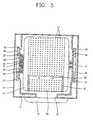
- Figure 3is a cross-sectional view showing a drum type washing machine according to an embodiment of the present invention
- Figure 4is a cross-sectional view in line IV-IV direction in Figure 3
- Figure 5is a cross-sectional view in line V-V direction in Figure 3 .
- the drum type washing machinecomprises: a cabinet 10 forming an outer appearance of the washing machine; a tub 11 formed integrally with the cabinet 10 for storing washing water; and a drum 12 disposed in the tub 11 to be rotatable for washing and drying laundries.
- the cabinet 10is formed as a rectangle having an inlet 13 through which the laundries are put/drawn formed on a front portion thereof and a cabinet door 14 for opening/closing the inlet 13 formed on the inlet 13.
- the tub 11is formed as a cylinder disposed in the cabinet 10.
- a front portion of the tub 11is fixed or integrally formed on a boundary surface of the inlet 13 of the cabinet 10 as opened status, and a rear portion of the tub 11 is fixed or integrally formed on a rear surface of the cabinet 10.
- penetrating holes 15 of circular shape having a predetermined diameter respectivelyare formed on both planes of the tub 11.
- the drum 12is a cylinder having shorter diameter than that of the tub 11 and disposed in the tub 11 to be rotatable.
- a plurality of washing water holes 17 through which the washing water goes in/outare formed on boundary direction of the drum 12, and both side surfaces of the drum 12 are sealed respectively.
- an inlet 16 through which the laundries can be put/drawn in order to receive the laundries in the drum 12is formed on a circumferential surface of the drum 12, and a drum door 18 for opening/closing the inlet 16 is installed on the inlet 16 of the drum to be opened/closed.
- a hinge shaft 19 for supporting the drum 12 to be rotatableis fixed on a center of one side surface of the drum 12, and a driving axis 21 for rotating the drum 12 by connecting with a driving motor 20 is fixed on a center of the other side surface of the drum 12.
- the hinge shaft 19is fixed on the center of one side surface of the drum 12 which is formed as a plane shape and is supported by a first supporting frame 22 to be rotatable.
- the first supporting frame 22is formed as a disc having a predetermined diameter and a supporting hole 24 penetrated a center thereof so that the hinge shaft 19 can be inserted therein.
- a first gasket 23 for preventing the washing water filled in the tub 11 from being leaked to outside of the tub 11is installed between an outer circumferential surface of the first supporting frame 22 and an inner circumferential surface of the penetrating hole 14 of the tub 11.
- a bearing 25 for supporting the hinge shaft 19 so as to be rotatableis installed between the inner circumferential surface of the supporting hole 24 on the first supporting frame 22 and the outer circumferential surface of the hinge shaft 19, and a first reinforcing plate 26 for reinforcing the supporting frame 22 is mounted on a rear surface of the first supporting frame 22.
- the first gasket 23is formed as a folded ring type having a predetermined width.
- the driving motor 20comprises: a rotor 27 formed integrally with the driving axis 21 and fixed on the other side surface of the drum 12; and a stator 28 located on the inner circumferential surface of the rotor 27 with a predetermined gap from the rotor 27 and rotating the rotor 27 by interacting with the rotor 27 when the power source is applied.
- the rotor 27has a front surface fixed on the center of the other side surface of the drum 12, and a magnet 29 is mounted on inner surface boundary direction of the rotor 27.
- the driving axis 21is supported by a second supporting frame 30 to be rotatable, and the second supporting frame 30 is formed as a disc having a predetermined diameter.
- a bearing 32 for supporting the driving axis 21 to be rotatableis mounted between an inner circumferential surface of the supporting hole 31 formed on the center portion of the second supporting frame 30 and an outer circumferential surface of the driving axis 21, and the stator 28 is fixed on the front surface of the second supporting frame 30.
- a second gasket 33 for preventing the washing water filled in the tub 11 from being leakedis mounted between the outer circumferential surface of the second supporting frame 30 and the inner circumferential surface of the penetrating hole 15 of the tub 11, and a second reinforcing plate 34 for reinforcing the second supporting frame 30 is mounted on a rear surface of the second supporting frame.
- the second gasket 33has same shape as that of the first gasket 23.
- Buffing springs 35 for absorbing the shock generated when the drum 12 is rotatedare installed between the first and second reinforcing plates 26 and 34 and upper inner wall of the cabinet 10, and dampers 36 for absorbing vibration are installed between the first and second reinforcing plates 26 and 34 and the lower inner wall of the cabinet 10.
- the hinge shaft 19 and the driving axis 21 which are fixed on the drum 12are supported respectively on the first and second supporting plates 26 and 34, and thereby, the vibration generated due to the rotation of the drum 12 is softened and absorbed by the buffing springs 35 and the dampers 36.
- Figure 6is a partial perspective view showing a drum door of the drum type washing machine according to the present invention.
- Guide rails 37are installed on both sides of the inlet 16 of the drum 12 for guiding the drum door 18 as a predetermined length toward the circumferential direction, and the drum door 18 is a plate type having same curvature rate as that of the circumferential surface of the drum 12 and having a plurality of washing water in/out holes 39.
- both side surface of the door 18are inserted in the guide rails 37 and moved along with the guide rails 37 to open/close the inlet 16 of the drum 12.
- a door handle 38 for the user to open/close manuallyis installed on one side of the drum door 18, and a locking device for locking the drum door 18 after closing the drum door 18 is installed on the door handle 38.
- the locking devicecomprises: a housing 40 fixed on front end portion of the drum door 18 to have a predetermined space; a locking rod 41 inserted into the housing 40 to be reciprocated in up-and-down direction and formed integrally with the door handle 38; a spring 43 disposed between a stopper 42 fixed on one side of the locking rod 41 and the inner wall of the housing 40 for granting a certain elastic force to the locking rod 41; and a locking hole 44 formed on one side of the inlet 16 of the drum 12 so that the locking rod 41 is inserted therein.
- the locking rod 41 formed integrally with the door handle 38is moved upward due to the elastic force of the spring 43. And when the user releases the handle after closing the drum door 18 in above status, the locking rod 41 is inserted into the locking hole 44 formed on the drum 12 by the elastic force of the spring to prevent the drum door 18 from being opened.
- the laundriesare put into the drum 12 after opening the cabinet door 14 and the drum door 18, and then, the drum door 18 and the cabinet door 14 are closed. That is, the door handle 38 is moved toward the closing direction of the inlet 16 of the drum 12 as holding the door handle 38, and after that, the lock rod 41 is set to be located on the locking hole 44 by pulling the door handle 38 upward and the door handle 38 is released. Then, the locking rod 41 is inserted into the locking hole 44 by the elastic force of the spring 43 and the closed status of the drum door 18 is maintained.
- the driving motor 20is operated to rotate the drum 12 and perform the washing and drying processes.
- the both side surfaces of the drum 12are supported by the hinge shaft 19 and by the driving axis 21 to be rotatable, and therefore, the drum 12 rotated more stably.
- the shock and vibration generated when the drum 12 is rotatedis buffed by the buffing spring 35 and, the damper 36 disposed between the first and second reinforcing plates 26 and 34 fixed on the first and second supporting frames 22 and 30 supporting the hinge shaft 19 and the driving axis 21 and the cabinet 10.
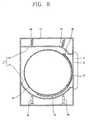
- Figure 8is a cross-sectional view showing a drum type washing machine according to a second embodiment of the present invention.
- the drum type washing machine according to the second embodimenthas same structures and operations as those of the above embodiment except the tub 11.
- the tub 11comprises: a first separating wall portion 46 integrally fixed between upper front wall and rear inner wall of the cabinet 10 and straightly formed; and a second separating wall portion 47 integrally fixed on the lower front inner wall and the rear inner wall of the cabinet 10 and formed as a curved plate.
- Figure 9is a cross-sectional view showing a drum type washing machine according to a third embodiment of the present invention
- Figure 10is a cross-sectional view in line X-X direction in Figure 9 .
- the drum type washing machinecomprises: a cabinet 10 forming an outer appearance of the washing machine; a tub 11 formed integrally with the cabinet 10 for storing washing water; a drum 12 disposed in the tub 11 to be rotatable for washing and drying the laundries; a drum door 50 formed on a circumferential surface of the drum 12 for opening/ctosing an inlet through which the laundries come in/go out; and a door opening/closing device for opening/closing the drum door 50 automatically.
- the cabinet 10 and the tub 11have same structures and operations as those of the above embodiment, and therefore, descriptions for those will be omitted.
- the drum 12 according to the third embodimentis formed as a cylinder having shorter diameter than that of the tub 11 and both side surfaces sealed.
- the hinge shaft 19 for supporting the drum 12 to be rotatableis fixed on a center of one side surface, and the rotor 27 of the driving motor 20 rotating the drum 12 is fixed on a center of the other side surface.
- an inlet 52 through which the laundries come in/go outis formed on the circumferential surface of the drum 12 in order to put the laundries into the drum 12, and the drum door 50 for opening/closing the inlet 52 is installed on the inlet 52 of the drum 12 to be opened/closed.
- a plurality of suspending rods 54 for preventing the drum door 50 from moving more than a predetermined degree by suspending the drum door 50are installed on one end portion of the drum inlet 52, and a plurality of locking rods 56 for locking the closed status of the drum door 50 are formed on the other end portion of the drum inlet 52.
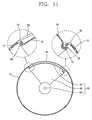
- Figure 11is a cross-sectional view showing a status that the drum door of the drum type washing machine according to the third embodiment of the present invention is closed
- Figure 12is a cross-sectional view showing a status that the drum door of the drum type washing machine according to the third embodiment of the present invention is opened.
- the drum door 50comprises: a sealed portion 60 formed as an arc having same size as that of the drum inlet 52 for closing the drum inlet 52; connecting portions 62 extended from both end portions of the sealing portion 60 toward the center of the drum 12 as a sector form; and door hinge shafts mounted on end portions of the connecting portions 62 for supporting the drum door 50 to be rotatable.
- a plurality of entrance holes through which the washing water comes in/ goes outare formed on the sealing portion 60.
- a suspending hook 66 for preventing the drum door 50 from moving more toward the closing direction by suspending on the suspending rod 54 of the door inlet 52is formed on one end portion of the sealing portion 60
- a locking hook 68 for maintaining the closed status of the drum door 50 by being inserted into the locking rod 56 of the door inlet 52is formed on the other end portion of the sealing portion 60.
- the locking hook 68is formed on the end portion of the sealing portion 60 to be elastically transformed, and located as escaped from the locking rod 56, that is, located with a certain distance from the locking rod 56 when the drum 12 is in stopped status, not to interrupt the opening operation of the drum door 50.
- a weighed body 70 having a predetermined weightis fixed on the locking hook 68 or integrally formed with the locking hook 68. Therefore, when the drum 12 is rotated, centrifugal force is applied to the weighed body 70, and accordingly, the locking hook 68 is elastically transformed and inserted in the locking rod 56 to lock the drum door 50.
- the door hinge shafts 64 connected to the both sides of the drum door 50are inserted in the penetrating holes 74 formed on the hinge shaft 19 and on the driving axis 21 supporting the drum 12 to be rotatable, and supported by them to be rotatable.
- the door opening/closing device for opening/closing the drum door 50automatically is installed on the door hinge shaft 64 which is inserted in to the hinge shaft 19 supporting the drum 12.
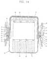
- Figure 14is a cross-sectional view showing the door opening/closing device according to the third embodiment of the present invention
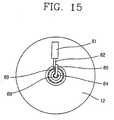
- Figure 15is a rear view showing the door opening/closing device according to the third embodiment of the present invention
- Figure 16is a block diagram showing a controlling means of the door opening/closing device according to the third embodiment of the present invention.
- the door opening/closing devicecomprises: a suspending rod 80 extended integrally from the end portion of the door hinge shaft 64, an actuator 81 for restricting the rotation of the suspending rod 80, and a controlling means for controlling the actuator 81 or the drum 12 so as to open/close the drum door 50.
- a backspin preventing means for preventing the drum door 50 from rotating toward the closing directionis installed on the door hinge shaft 64.
- the suspending rod 80is bent on the end portion of the door hinge shaft 64 as a right angle, and then, the rotation of the suspending rod 80 is restricted when the actuator 81 is operated.
- a push rod 82 for restricting the rotation of the suspending rod 80 by contacting to the side surface of the suspending rod 80is inserted into the actuator 81, and the actuator 81 is fixed on the rear surface of the first reinforcing plate 26. It is desirable that the actuator 81 is formed as a solenoid type which drives the push rod 82 as pushing it when the power source is applied.
- the controlling meanscomprises a drum position detector 84 for detecting the position of the drum 12, a driving motor 20 for driving the drum 12 after being applied a signal of the drum position detector 84, and a control unit 85 for operating the actuator 81.
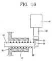
- Figures 17 and 18are cross-sectional views showing a backspin preventing means of the drum type washing machine according to the third embodiment of the present invention.
- the backspin preventing meansis a backspin preventing spring 88 having one end portion fixed on the hinge shaft 19 which is fixed on the drum 12 and the other end portion extended along with the suspending rod 80 to be a predetermined length and located to be face the front surface of the push rod 82 of the actuator 81.
- the backspin preventing meansmay be a one-way clutch which is installed on the door hinge shaft 64 for preventing the drum door 18 from moving toward the opening direction.
- the actuator 81When the laundries are put into the drum 12 through the drum inlet 52 as opening the cabinet door 14 and then the cabinet door 14 is closed and the power switch is turned on, the actuator 81 is operated according to the controlling signal of the control unit 85. Then, the push rod 82 is straightly moved to contact to the side surface of the suspending rod 80, and at the same time, to push the one end portion 87 of the backspin preventing spring 88. Therefore, the backspin preventing spring 88 is released from the door hinge shaft 64 to release the locked status of the drum door 50.
- the suspending hook 66 of the drum door 50is coupled to the suspending rod 80 installed on one side of the drum inlet 52 to prevent the drum door 50 from moving more than the status that the drum door 50 closes the drum inlet 52.
- washing and drying operationsare performed as the drum 12 is rotated by the normal operation of the driving motor 20.
- the locking hook 68 of the drum door 50is elastically transformed by the centrifugal force of the drum 12, and then, inserted into the locking rod 56 installed on the drum inlet 52 to maintain the status that the drum door 40 is closed on the drum inlet 52.
- the backspin preventing spring 88is operated to prevent the drum door 50 from being opened. That is, when the drum 12 is rotated toward the direction of opening the drum door 40, the backspin preventing spring 88 compresses the outer circumferential surface of the door hinge shaft 64 to prevent the drum door 50 from being opened.
- the drum 12is stopped at the set position, and the opening operation of the drum door 50 is performed and the laundries are drawn from the drum 12.
- control unit 85controls the driving motor 20 according to the signal applied from the drum position detector 84 so that the drum 12 can be stopped at the set position, and drives the actuator 81. Then, the push rod 82 is straightly moved and contacted to the side surface of the suspending rod 80 to restrict the drum door 50 not to rotate. In above status, the control unit 85 operates the driving motor 20 again to rotate the drum 12, and thereby, the drum inlet 52 is opened from the drum door 50.
- the tubis fixed inside the cabinet, and therefore, the size of the drum can be maximized. Therefore, the washing capacity of the drum can be increased without increasing the size of the cabinet. Also, the installation space of the driving motor can be minimized by fixing the rotor of the driving motor onto the drum directly, and therefore, the washing capacity can be increased and the entire size of the washing machine can be compacted.
- the drumcan be rotated stably in the washing and drying operations.
- the drum dooropens/closes the drum inlet formed on the circumferential surface of the drum automatically, and thereby, the convenience in usage can be increased.
Landscapes
- Engineering & Computer Science (AREA)
- Textile Engineering (AREA)
- Main Body Construction Of Washing Machines And Laundry Dryers (AREA)
Description
- The present invention relates to a drum type washing machine, and particularly, to a drum type washing machine which is able to maximize washing capacity without changing entire size of the washing machine.
Figure 1 is a cross-sectional view showing a drum type washing machine according to the conventional art, andFigure 2 is a front view showing the drum type washing machine according to the conventional art.- The drum type washing machine according to the conventional art comprises: a
cabinet 102 forming an outer appearance of the washing machine; atub 104 disposed inside thecabinet 102 for storing washing water; adrum 106 disposed inside thetub 104 to be rotatable for washing and drying laundries; and a drivingmotor 110 located on a rear portion of thetube 104 and connected with thedrum 106 through adriving axis 108 for rotating thedrum 106. - An
inlet 112 is formed on a front portion of thecabinet 102 so as to put or to draw the laundries, and adoor 114 is disposed on a front portion of theinlet 112. - The
tub 104 is a cylindrical shape having anopening 116 on the front portion thereof so as to be communicated with theinlet 112 of thecabinet 102, and a diameter of thetub 104 is designed to be 30 ∼ 40mm shorter than a width of thecabinet 102 so as to prevent from contacting to thecabinet 102 in drying process. - The
drum 106 is a cylinder shape with an opened end so that the laundries can be put/drawn. In addition, since thedrum 106 is rotated in thetub 104, adiameter 106 is designed to be 15 ∼ 20mm shorter than that of thetub 104 in order to prevent interruption between thetub 104. - A plurality of supporting
springs 120 are installed between an upper part of the tub104 and an inner upper wall of thecabinet 102, and a plurality ofdampers 122 are installed between a lower part of thetub 104 and an inner lower wall of thecabinet 102 to support thetub 104 so as to buff the shock. - A
gasket 124 is installed between theinlet 112 of thecabinet 102 and the opening 116 of thetub 104 in order to prevent the washing water stored in thetub 104 from being leaked into the space between thetub 104 and thecabinet 102. In addition, a supportingframe 126 where thedriving motor 110 is mounted is installed on a rear portion of thetub 104. - The
driving motor 110 is fixed on a rear surface of the supportingframe 126, and thedriving axis 108 of thedriving motor 110 is fixed on a lower surface of thedrum 106 to generate the driving force for rotating thedrum 106. - In the drum type washing machine according to the conventional art, the diameter of the
tub 104 is designed as considering maximum vibration width of thetub 104 in thecabinet 102 for preventing thetub 104 from contacting to thecabinet 102, and the diameter of thedrum 106 is also designed to be shorter than the diameter of thetub 104 in order to prevent the interruption between thetub 104 since thedrum 106 is rotated in thetub 104. Therefore, in order to increase the diameter of thedrum 106 which is directly related to the washing capacity, the size of thecabinet 102 should be increased. - Also, the
gasket 124 for preventing the washing water from being leaked is installed between theinlet 112 of thecabinet 102 and the opening 116 of thetub 104, and therefore, the length of thedrum 106 is reduced as much as the length of thegasket 124. Therefore, it is difficult to increase the capacity of thedrum 106. DE 101 54 208 A1 describes a drum lock for domestic devices, especially washing machines and dryers, wherein a drum being rotary driven is located in a fixed container, the drum being non-rotatably connected to a drive belt pulley, on which a locking device is applied, which consists of at least one axially movable locking piston which engages an aperture in the pulley. In order for the locking piston to be applicable to stronger locking and clamping forces it is intended that the locking piston is mechanically coupled to a force storage device loaded by an external force source.- Therefore, an object of the present invention is to provide a drum type washing machine which is able to increase washing capacity without increasing entire size of a washing machine by forming a cabinet and a tub integrally in order to increase a diameter of the drum without increasing a size of the cabinet.
- Another object of the present invention is to provide a drum type washing machine which is able to compact entire size of the washing machine while increasing washing capacity by minimizing installation space of a driving motor.
- Also, another object of the present invention is to provide a drum type washing machine in which a drum rotates more stably in washing and drying processes by supporting both sides of the drum to be rotatable.
- Still another object of the present invention is to provide a drum type washing machine which is able to increase convenience in using the washing machine by making a drum door opening/closing a drum operated automatically.
- To achieve these objects of the present invention, as embodied and broadly described herein, there is provided a drum type washing machine according to the present invention comprising: a cabinet making an outer appearance of the washing machine; a tub fixed inside of the cabinet for storing washing water; a drum disposed in the tub, having both side surfaces supported by the cabinet to be rotatable and an inlet, through which laundries are put/drawn, formed on a circumferential surface thereof; and a driving motor fixed on one side surface of the drum for generating driving force which rotates the drum.
- The tub is formed as a cylinder having a front portion formed integrally on a front inner wall of the cabinet and a rear portion formed integrally on a rear inner wall of the cabinet.
- The tub comprises: a first separating wall portion integrally fixed between upper front inner wall of the cabinet and a rear inner wall of the cabinet; and a second separating wall portion fixed integrally on a lower front inner wall and the rear inner wall of the cabinet and formed as a curved surface.
- Penetrating holes are formed on both side surfaces of the tub, and a first and second supporting frames having shorter diameters than those of the penetrating holes are located on both side surface of the tube. In addition, gaskets are installed between an inner circumferential surface of the penetrating hole and outer circumferential surfaces of the first and second supporting frames respectively.
- The driving motor comprises: a rotor fixed on a side surface of the drum and a stator located on an inner circumferential surface of the rotor to interact with the rotor. In addition, the rotor is formed integrally with the driving axis and fixed on the side surface of the drum, and a magnet is mounted on the inner circumferential surface thereof.
- A drum door is installed on an inlet of the drum for opening/closing the inlet, and guide rails for guiding the drum door so as to be moved are formed on both side surfaces of the drum inlet to be a predetermined length.
- A locking system for locking the drum door is installed on the drum door, and the locking system comprises: a housing fixed on the front portion of the drum door so as to have a predetermined space; a locking rod inserted into the housing to be moved in up-and-down direction; a spring disposed between a stopper fixed on one side of the locking rod and an inner wall of the housing for granting a predetermined elastic force to the locking rod; and a locking hole, in which the locking rod is inserted, formed on one side of the drum inlet.
- Also, there is provided a drum type washing machine comprising: a cabinet forming an outer appearance; a tub fixed in the cabinet for storing washing water; a drum disposed in the tub, having both side surfaces supported by the cabinet to be rotatable and an inlet, through which laundries are put/drawn, formed on a circumferential surface thereof; a drum door installed on the inlet of the drum for opening/closing the drum inlet; and a door opening/closing device for automatically opening/closing the drum door.
- The door opening/closing device comprises a suspending rod connected to an end portion of a hinge shaft of the door; an actuator mounted on one side of the suspending rod for restricting the rotation of the suspending rod; and a controlling means for driving the actuator and rotating the drum for opening/closing the drum door.
- The controlling means comprises: a drum location detecting device for detecting the location of the drum; and a control unit for driving the driving motor and the actuator according to a signal applied from the drum location detecting device.
- A backspin preventing means is installed on the door hinge shaft for preventing the drum door from rotating toward the opening direction, and the backspin preventing means is a backspin preventing spring wound on the door hinge shaft having one end portion fixed on a hinge shaft supporting the drum and the other end portion extended to be a predetermined length along with the suspending rod.
- The foregoing and other objects, features, aspects and advantages of the present invention will become more apparent from the following detailed description of the present invention when taken in conjunction with the accompanying drawings.
- The accompanying drawings, which are included to provide a further understanding of the invention and are incorporated in and constitute a part of this specification, illustrate embodiments of the invention and together with the description serve to explain the principles of the invention.
- In the drawings:
Figure 1 is a cross-sectional view showing a drum type washing machine according to the conventional art;Figure 2 is a cross-sectional view in line II-II direction inFigure 1 ;Figure 3 is a cross-sectional view showing a drum type washing machine according to an embodiment of the present invention;Figure 4 is a cross-sectional view in line IV-IV direction shown inFigure 3 ;Figure 5 is a cross-sectional view in line V-V direction shown inFigure 3 ;Figure 6 is a partial perspective view showing a drum cover of the drum type washing machine according to the embodiment of the present invention;Figure 7 is an enlarged cross-sectional view showing A part ofFigure 6 ;Figure 8 is a cross-sectional view showing a drum type washing machine according to a second embodiment of the present invention;Figure 9 is a cross-sectional view showing a drum type washing machine according to a third embodiment of the present invention;Figure 10 is a cross-sectional view in line X-X direction inFigure 9 ;Figure 11 . is a cross-sectional view showing a status that a drum door of the drum type washing machine according to the third embodiment of the present invention is closed;Figure 12 is a cross-sectional view showing a status that a drum door of the drum type washing machine according to the third embodiment of the present invention is closed;Figure 13 is an enlarged view showing part B inFigure 12 ;Figure 14 is a cross-sectional view showing a door opening/closing device of the drum type washing machine according to the third embodiment of the present invention;Figure 15 is a rear view showing the door opening/closing device of the drum type washing machine according to the third embodiment of the present invention;Figure 16 is a block diagram showing a controlling means of the door opening/closing device of the drum type washing machine according to the third embodiment of the present invention; andFigures 17 and18 are partial cross-sectional views showing a door backspin preventing device of the drum type washing machine according to the third embodiment of the present invention.- Reference will now be made in detail to the preferred embodiments of the present invention, examples of which are illustrated in the accompanying drawings.
Figure 3 is a cross-sectional view showing a drum type washing machine according to an embodiment of the present invention,Figure 4 is a cross-sectional view in line IV-IV direction inFigure 3 , andFigure 5 is a cross-sectional view in line V-V direction inFigure 3 .- The drum type washing machine according to the embodiment of the present invention comprises: a
cabinet 10 forming an outer appearance of the washing machine; atub 11 formed integrally with thecabinet 10 for storing washing water; and adrum 12 disposed in thetub 11 to be rotatable for washing and drying laundries. - The
cabinet 10 is formed as a rectangle having aninlet 13 through which the laundries are put/drawn formed on a front portion thereof and acabinet door 14 for opening/closing theinlet 13 formed on theinlet 13. - The
tub 11 is formed as a cylinder disposed in thecabinet 10. In addition, a front portion of thetub 11 is fixed or integrally formed on a boundary surface of theinlet 13 of thecabinet 10 as opened status, and a rear portion of thetub 11 is fixed or integrally formed on a rear surface of thecabinet 10. And penetratingholes 15 of circular shape having a predetermined diameter respectively are formed on both planes of thetub 11. - The
drum 12 is a cylinder having shorter diameter than that of thetub 11 and disposed in thetub 11 to be rotatable. In addition, a plurality ofwashing water holes 17 through which the washing water goes in/out are formed on boundary direction of thedrum 12, and both side surfaces of thedrum 12 are sealed respectively. In addition, aninlet 16 through which the laundries can be put/drawn in order to receive the laundries in thedrum 12 is formed on a circumferential surface of thedrum 12, and adrum door 18 for opening/closing theinlet 16 is installed on theinlet 16 of the drum to be opened/closed. - A
hinge shaft 19 for supporting thedrum 12 to be rotatable is fixed on a center of one side surface of thedrum 12, and a drivingaxis 21 for rotating thedrum 12 by connecting with a drivingmotor 20 is fixed on a center of the other side surface of thedrum 12. - The
hinge shaft 19 is fixed on the center of one side surface of thedrum 12 which is formed as a plane shape and is supported by a first supportingframe 22 to be rotatable. Herein, the first supportingframe 22 is formed as a disc having a predetermined diameter and a supportinghole 24 penetrated a center thereof so that thehinge shaft 19 can be inserted therein. In addition, afirst gasket 23 for preventing the washing water filled in thetub 11 from being leaked to outside of thetub 11 is installed between an outer circumferential surface of the first supportingframe 22 and an inner circumferential surface of the penetratinghole 14 of thetub 11. - Herein, a
bearing 25 for supporting thehinge shaft 19 so as to be rotatable is installed between the inner circumferential surface of the supportinghole 24 on the first supportingframe 22 and the outer circumferential surface of thehinge shaft 19, and a first reinforcingplate 26 for reinforcing the supportingframe 22 is mounted on a rear surface of the first supportingframe 22. - The
first gasket 23 is formed as a folded ring type having a predetermined width. - The driving
motor 20 comprises: arotor 27 formed integrally with the drivingaxis 21 and fixed on the other side surface of thedrum 12; and astator 28 located on the inner circumferential surface of therotor 27 with a predetermined gap from therotor 27 and rotating therotor 27 by interacting with therotor 27 when the power source is applied. - Herein, the
rotor 27 has a front surface fixed on the center of the other side surface of thedrum 12, and amagnet 29 is mounted on inner surface boundary direction of therotor 27. - The driving
axis 21 is supported by a second supportingframe 30 to be rotatable, and the second supportingframe 30 is formed as a disc having a predetermined diameter. In addition, abearing 32 for supporting the drivingaxis 21 to be rotatable is mounted between an inner circumferential surface of the supportinghole 31 formed on the center portion of the second supportingframe 30 and an outer circumferential surface of the drivingaxis 21, and thestator 28 is fixed on the front surface of the second supportingframe 30. - In addition, a
second gasket 33 for preventing the washing water filled in thetub 11 from being leaked is mounted between the outer circumferential surface of the second supportingframe 30 and the inner circumferential surface of the penetratinghole 15 of thetub 11, and a second reinforcingplate 34 for reinforcing the second supportingframe 30 is mounted on a rear surface of the second supporting frame. - Herein, the
second gasket 33 has same shape as that of thefirst gasket 23. - Buffing springs 35 for absorbing the shock generated when the
drum 12 is rotated are installed between the first and second reinforcingplates cabinet 10, anddampers 36 for absorbing vibration are installed between the first and second reinforcingplates cabinet 10. - That is, the
hinge shaft 19 and the drivingaxis 21 which are fixed on thedrum 12 are supported respectively on the first and second supportingplates drum 12 is softened and absorbed by the buffing springs 35 and thedampers 36. Figure 6 is a partial perspective view showing a drum door of the drum type washing machine according to the present invention.Guide rails 37 are installed on both sides of theinlet 16 of thedrum 12 for guiding thedrum door 18 as a predetermined length toward the circumferential direction, and thedrum door 18 is a plate type having same curvature rate as that of the circumferential surface of thedrum 12 and having a plurality of washing water in/out holes 39. In addition, both side surface of thedoor 18 are inserted in the guide rails 37 and moved along with the guide rails 37 to open/close theinlet 16 of thedrum 12.- Herein, a
door handle 38 for the user to open/close manually is installed on one side of thedrum door 18, and a locking device for locking thedrum door 18 after closing thedrum door 18 is installed on thedoor handle 38. - As shown in
Figure 7 , the locking device comprises: ahousing 40 fixed on front end portion of thedrum door 18 to have a predetermined space; a lockingrod 41 inserted into thehousing 40 to be reciprocated in up-and-down direction and formed integrally with thedoor handle 38; aspring 43 disposed between astopper 42 fixed on one side of the lockingrod 41 and the inner wall of thehousing 40 for granting a certain elastic force to the lockingrod 41; and alocking hole 44 formed on one side of theinlet 16 of thedrum 12 so that the lockingrod 41 is inserted therein. - That is, in the above locking device, when the user pulls the
door handle 38, the lockingrod 41 formed integrally with thedoor handle 38 is moved upward due to the elastic force of thespring 43. And when the user releases the handle after closing thedrum door 18 in above status, the lockingrod 41 is inserted into the lockinghole 44 formed on thedrum 12 by the elastic force of the spring to prevent thedrum door 18 from being opened. - Operations of the drum type washing machine constructed as above according to the present invention will be described as follows.
- The laundries are put into the
drum 12 after opening thecabinet door 14 and thedrum door 18, and then, thedrum door 18 and thecabinet door 14 are closed. That is, thedoor handle 38 is moved toward the closing direction of theinlet 16 of thedrum 12 as holding thedoor handle 38, and after that, thelock rod 41 is set to be located on the lockinghole 44 by pulling thedoor handle 38 upward and thedoor handle 38 is released. Then, the lockingrod 41 is inserted into the lockinghole 44 by the elastic force of thespring 43 and the closed status of thedrum door 18 is maintained. - In above status, when a power switch is turned on, the washing water is induced into the
tub 11. At that time, the front and rear portions of thetub 11 are integrally fixed on thecabinet 10 respectively, and the penetratingholes 15 formed on both side surfaces are connected to the first and second supportingframes gaskets tub 11 is not leaked to outside. - When the inducing of washing water is completed, the driving
motor 20 is operated to rotate thedrum 12 and perform the washing and drying processes. - Herein, the both side surfaces of the
drum 12 are supported by thehinge shaft 19 and by the drivingaxis 21 to be rotatable, and therefore, thedrum 12 rotated more stably. In addition, the shock and vibration generated when thedrum 12 is rotated is buffed by the buffingspring 35 and, thedamper 36 disposed between the first and second reinforcingplates frames hinge shaft 19 and the drivingaxis 21 and thecabinet 10. - In addition, when the power source is applied to the
stator 28 of the drivingmotor 20, therotor 27 fixed on the surface of thedrum 12 is rotated to rotate thedrum 12. - At that time, since the
rotor 27 is fixed on the side surface of thedrum 12, the space where the drivingmotor 20 is installed can be reduced greatly. Figure 8 is a cross-sectional view showing a drum type washing machine according to a second embodiment of the present invention.- The drum type washing machine according to the second embodiment has same structures and operations as those of the above embodiment except the
tub 11. - That is, the
tub 11 according to the second embodiment comprises: a firstseparating wall portion 46 integrally fixed between upper front wall and rear inner wall of thecabinet 10 and straightly formed; and a secondseparating wall portion 47 integrally fixed on the lower front inner wall and the rear inner wall of thecabinet 10 and formed as a curved plate. Figure 9 is a cross-sectional view showing a drum type washing machine according to a third embodiment of the present invention, andFigure 10 is a cross-sectional view in line X-X direction inFigure 9 .- The drum type washing machine according to the third embodiment comprises: a
cabinet 10 forming an outer appearance of the washing machine; atub 11 formed integrally with thecabinet 10 for storing washing water; adrum 12 disposed in thetub 11 to be rotatable for washing and drying the laundries; adrum door 50 formed on a circumferential surface of thedrum 12 for opening/ctosing an inlet through which the laundries come in/go out; and a door opening/closing device for opening/closing thedrum door 50 automatically. - The
cabinet 10 and thetub 11 have same structures and operations as those of the above embodiment, and therefore, descriptions for those will be omitted. - The
drum 12 according to the third embodiment is formed as a cylinder having shorter diameter than that of thetub 11 and both side surfaces sealed. In addition thehinge shaft 19 for supporting thedrum 12 to be rotatable is fixed on a center of one side surface, and therotor 27 of the drivingmotor 20 rotating thedrum 12 is fixed on a center of the other side surface. - In addition, an
inlet 52 through which the laundries come in/go out is formed on the circumferential surface of thedrum 12 in order to put the laundries into thedrum 12, and thedrum door 50 for opening/closing theinlet 52 is installed on theinlet 52 of thedrum 12 to be opened/closed. - Herein, a plurality of suspending
rods 54 for preventing thedrum door 50 from moving more than a predetermined degree by suspending thedrum door 50 are installed on one end portion of thedrum inlet 52, and a plurality of lockingrods 56 for locking the closed status of thedrum door 50 are formed on the other end portion of thedrum inlet 52. Figure 11 is a cross-sectional view showing a status that the drum door of the drum type washing machine according to the third embodiment of the present invention is closed, andFigure 12 is a cross-sectional view showing a status that the drum door of the drum type washing machine according to the third embodiment of the present invention is opened.- The
drum door 50 comprises: a sealedportion 60 formed as an arc having same size as that of thedrum inlet 52 for closing thedrum inlet 52; connectingportions 62 extended from both end portions of the sealingportion 60 toward the center of thedrum 12 as a sector form; and door hinge shafts mounted on end portions of the connectingportions 62 for supporting thedrum door 50 to be rotatable. - A plurality of entrance holes through which the washing water comes in/ goes out are formed on the sealing
portion 60. In addition, a suspendinghook 66 for preventing thedrum door 50 from moving more toward the closing direction by suspending on the suspendingrod 54 of thedoor inlet 52 is formed on one end portion of the sealingportion 60, and alocking hook 68 for maintaining the closed status of thedrum door 50 by being inserted into the lockingrod 56 of thedoor inlet 52 is formed on the other end portion of the sealingportion 60. - As shown in
Figure 13 , the lockinghook 68 is formed on the end portion of the sealingportion 60 to be elastically transformed, and located as escaped from the lockingrod 56, that is, located with a certain distance from the lockingrod 56 when thedrum 12 is in stopped status, not to interrupt the opening operation of thedrum door 50. - In addition, a weighed
body 70 having a predetermined weight is fixed on the lockinghook 68 or integrally formed with the lockinghook 68. Therefore, when thedrum 12 is rotated, centrifugal force is applied to the weighedbody 70, and accordingly, the lockinghook 68 is elastically transformed and inserted in the lockingrod 56 to lock thedrum door 50. - The
door hinge shafts 64 connected to the both sides of thedrum door 50 are inserted in the penetratingholes 74 formed on thehinge shaft 19 and on the drivingaxis 21 supporting thedrum 12 to be rotatable, and supported by them to be rotatable. In addition, the door opening/closing device for opening/closing thedrum door 50 automatically is installed on thedoor hinge shaft 64 which is inserted in to thehinge shaft 19 supporting thedrum 12. Figure 14 is a cross-sectional view showing the door opening/closing device according to the third embodiment of the present invention, andFigure 15 is a rear view showing the door opening/closing device according to the third embodiment of the present invention, andFigure 16 is a block diagram showing a controlling means of the door opening/closing device according to the third embodiment of the present invention.- As shown in
Figure 14 , the door opening/closing device comprises: a suspendingrod 80 extended integrally from the end portion of thedoor hinge shaft 64, anactuator 81 for restricting the rotation of the suspendingrod 80, and a controlling means for controlling theactuator 81 or thedrum 12 so as to open/close thedrum door 50. - In addition, a backspin preventing means for preventing the
drum door 50 from rotating toward the closing direction is installed on thedoor hinge shaft 64. - The suspending
rod 80 is bent on the end portion of thedoor hinge shaft 64 as a right angle, and then, the rotation of the suspendingrod 80 is restricted when theactuator 81 is operated. - A
push rod 82 for restricting the rotation of the suspendingrod 80 by contacting to the side surface of the suspendingrod 80 is inserted into theactuator 81, and theactuator 81 is fixed on the rear surface of the first reinforcingplate 26. It is desirable that theactuator 81 is formed as a solenoid type which drives thepush rod 82 as pushing it when the power source is applied. - As shown in
Figure 16 , the controlling means comprises adrum position detector 84 for detecting the position of thedrum 12, a drivingmotor 20 for driving thedrum 12 after being applied a signal of thedrum position detector 84, and acontrol unit 85 for operating theactuator 81. Figures 17 and18 are cross-sectional views showing a backspin preventing means of the drum type washing machine according to the third embodiment of the present invention.- The backspin preventing means is a
backspin preventing spring 88 having one end portion fixed on thehinge shaft 19 which is fixed on thedrum 12 and the other end portion extended along with the suspendingrod 80 to be a predetermined length and located to be face the front surface of thepush rod 82 of theactuator 81. - As shown in
Figure 17 , if the force is compressed toward the direction of opening thedrum door 18 by the centrifugal force when thedrum 12 is driven toward the reverse direction in washing and drying processes, the force is compressed toward the direction of winding thebackspin preventing spring 88. Accordingly, thespring 88 is compressed on the outer circumferential surface of thedoor hinge shaft 64 to prevent thedrum door 18 from being opened. - In addition, as shown in
Figure 18 , when thepush rod 82 pushes theend portion 87 of thespring 88 by the operation of theactuator 81, thespring 88 is released from thedoor hinge shaft 64 and thedrum door 50 can be rotated freely. - The backspin preventing means may be a one-way clutch which is installed on the
door hinge shaft 64 for preventing thedrum door 18 from moving toward the opening direction. - Operations of the drum type washing machine constructed as above according to the third embodiment of the present invention will be described as follows.
- When the laundries are put into the
drum 12 through thedrum inlet 52 as opening thecabinet door 14 and then thecabinet door 14 is closed and the power switch is turned on, theactuator 81 is operated according to the controlling signal of thecontrol unit 85. Then, thepush rod 82 is straightly moved to contact to the side surface of the suspendingrod 80, and at the same time, to push the oneend portion 87 of thebackspin preventing spring 88. Therefore, thebackspin preventing spring 88 is released from thedoor hinge shaft 64 to release the locked status of thedrum door 50. - In above status, when the
control unit 85 operates the drivingmotor 20, thedrum 12 is rotated toward the direction of closing thedrum door 50, and then, thedrum door 50 is closed on thedrum inlet 52. - At that time, the suspending
hook 66 of thedrum door 50 is coupled to the suspendingrod 80 installed on one side of thedrum inlet 52 to prevent thedrum door 50 from moving more than the status that thedrum door 50 closes thedrum inlet 52. - In addition, the washing and drying operations are performed as the
drum 12 is rotated by the normal operation of the drivingmotor 20. At that time, the lockinghook 68 of thedrum door 50 is elastically transformed by the centrifugal force of thedrum 12, and then, inserted into the lockingrod 56 installed on thedrum inlet 52 to maintain the status that thedrum door 40 is closed on thedrum inlet 52. - That is, when the centrifugal force is applied by the weight of the weighed
body 70 fixed on the lockinghook 68, the lockinghook 68 is inserted into the lockingrod 56 while elastically transformed. - In addition, when the
drum 12 is rotated toward the direction of opening thedrum door 50 in the washing and drying operations, thebackspin preventing spring 88 is operated to prevent thedrum door 50 from being opened. That is, when thedrum 12 is rotated toward the direction of opening thedrum door 40, thebackspin preventing spring 88 compresses the outer circumferential surface of thedoor hinge shaft 64 to prevent thedrum door 50 from being opened. - After a predetermined time passes and the washing and drying operations are completed, the
drum 12 is stopped at the set position, and the opening operation of thedrum door 50 is performed and the laundries are drawn from thedrum 12. - That is, the
control unit 85 controls the drivingmotor 20 according to the signal applied from thedrum position detector 84 so that thedrum 12 can be stopped at the set position, and drives theactuator 81. Then, thepush rod 82 is straightly moved and contacted to the side surface of the suspendingrod 80 to restrict thedrum door 50 not to rotate. In above status, thecontrol unit 85 operates the drivingmotor 20 again to rotate thedrum 12, and thereby, thedrum inlet 52 is opened from thedrum door 50. - Effects of the drum type washing machine constructed and operated as above will be described as follows.
- According to the drum type washing machine of the present invention, the tub is fixed inside the cabinet, and therefore, the size of the drum can be maximized. Therefore, the washing capacity of the drum can be increased without increasing the size of the cabinet. Also, the installation space of the driving motor can be minimized by fixing the rotor of the driving motor onto the drum directly, and therefore, the washing capacity can be increased and the entire size of the washing machine can be compacted.
- Also, since the hinge shaft and the driving axis are fixed on center portions of the both sides of the drum and supported to be rotatable, the drum can be rotated stably in the washing and drying operations.
- Also, the drum door opens/closes the drum inlet formed on the circumferential surface of the drum automatically, and thereby, the convenience in usage can be increased.
- As the present invention may be embodied in several forms without departing from the spirit or essential characteristics thereof, it should also be understood that the above-described embodiments are not limited by any of the details of the foregoing description, unless otherwise specified, but rather should be construed broadly within its spirit and scope as defined in the appended claims, and therefore all changes and modifications that fall within the metes and bounds of the claims, or equivalence of such metes and bounds are therefore intended to be embraced by the appended claims.
Claims (18)
- A drum type washing machine comprising:a cabinet (10) forming an outer appearance;a tub (11) fixed inside the cabinet (10) for storing washing water;a drum (12) disposed in the tub (11) and having both side surfaces supported by the cabinet (10) to be rotatable and an inlet (52) at a circumferential surface thereof for loading and unloading laundry;a drum door (50) installed on the drum inlet (52) for opening/closing the drum inlet (52);a door opening/closing device for opening/closing the drum door (50) automatically, anda controlling means opening/closing the drum door (50),characterized in that the door opening/closing device comprises:a suspending rod (80) connected to an end portion of a door hinge shaft (64); andan actuator (81) mounted on one side of the suspending rod (80) for restricting the rotation of the suspending rod (80),wherein the controlling means opens/closes the drum door (50) by driving the actuator (81) and rotating the drum (12).
- The washing machine of claim 1, wherein the drum door (50) comprises:a sealing portion (60) formed as an arc having same size as that of the drum inlet (52) for opening/closing the drum inlet (52);connecting portions (62) extended from both end portions of the sealing portion (60) toward a center of the drum (12) as a sector form; anddoor hinge shafts (64) mounted on end portion of the connecting portion (62) for supporting the drum door (50) to be rotatable.
- The washing machine of claim 2, wherein a plurality of entrance holes through which the washing water comes in/goes out are formed on the sealing portion (60).
- The washing machine of claim 2, further comprising a locking device for locking the closed status of the drum door (59), the locking device is mounted between the sealing portion (60) and the drum inlet (52).
- The washing machine of claim 4, wherein the locking device comprises:suspending rods (54) formed on one end portion of the door inlet (52);suspending hooks (66) formed on one end portion of the sealing portion (60) and suspended on the suspending rods for restricting movement of the drum door (50) toward the closing direction;locking rods (68) formed on the other end portion of the door inlet (52); andlocking hooks (56) formed on the other end portion of the sealing portion (60) and inserted into the locking rods (68) for maintaining the closed status of the drum door (50).
- The washing machine of claim 5, wherein the locking hook (68) is formed to be elastically transformed, is located on a position escaped from the locking rod (56) in the state that the drum is stopped, and inserted into the locking rod (56) after being elastically transformed by the centrifugal force when the drum is rotated.
- The washing machine of claim 5, wherein the locking hook (68) includes a weighed body (70) so as to be elastically transformed by the centrifugal force when the drum (12) is rotated.
- The washing machine of claim 1, wherein the actuator (81) includes a push rod (82) which is straightly moved by contacting the side surface of the suspending rod (80) so as to restrict the rotation of the suspending rod (80).
- The washing machine of claim 1, wherein the controlling means comprises:a drum position detector (84) for detecting position of the drum (12); anda control unit (85) for operating a driving motor (20) and the actuator (81) according to signals applied from the drum position detector (84).
- The washing machine of claim 8, wherein a backspin preventing means (88) is installed on the door hinge shaft (64) for preventing the drum door (50) from rotating toward the opening direction.
- The washing machine of claim 1, further comprising: a driving motor (20) fixed on one side surface of the drum (12) to rotate the drum (12).
- The washing machine of claim 1, wherein the cabinet is formed as a rectangle comprising an inlet (13) through which the laundries can be entered/drawn and a cabinet door (14) for opening/closing the inlet (13).
- The washing machine of claim 1, wherein the tub (11) is formed as a cylinder having a front portion integrally formed on a front inner wall of the cabinet (10) and a rear portion integrally formed on a rear inner wall of the cabinet (10).
- The washing machine of claim 1, wherein the tub (11) comprises:a first separating wall portion (46) integrally fixed between an upper front inner wall of the cabinet (10) and a rear inner wall of the cabinet (10) and straightly formed; anda second separating wall portion (47) fixed integrally on a lower front inner wall and a rear inner wall of the cabinet and formed as a curved plate.
- The washing machine of claim 1, wherein penetrating holes (15) are formed on both side surfaces of the tub (11) respectively, a first and second supporting frames (22, 30) having shorter diameters than those of the penetrating holes (15) are located on both side surfaces of the tub (11), and gaskets (23, 33) are installed between inner circumferential surfaces of the penetrating holes (15) and outer circumferential surface of the first and second supporting frames (22, 30).
- The washing machine of claim 15, wherein the drum (12) is formed as a cylinder with sealed both sides and comprises a hinge shaft (19), which is supported by the first supporting frame (22) to be rotatable, fixed on a center of one side surface thereof and a driving axis (21), which is supported by the second supporting frame (30) to be rotatable, fixed on a center of the other side surface thereof.
- The washing machine of claim 16, wherein a buffing spring (35) is installed between the first and second reinforcing plates (26, 34) and an upper inner wall of the cabinet, and a damper (36) is installed between the first and second reinforcing plates (26, 34) and a lower inner wall of the cabinet.
- The washing machine of claim 11, wherein the driving motor (20) comprises a rotor (27) fixed on a side surface of the drum and a stator (28) located inside the rotor for interacting with the rotor (27), wherein the stator (28) is fixed on the front surface of the second supporting frame (22).
Applications Claiming Priority (3)
| Application Number | Priority Date | Filing Date | Title |
|---|---|---|---|
| KR10-2002-0085520AKR100492586B1 (en) | 2002-12-27 | 2002-12-27 | Drum type washing machine with united cabinet/tub |
| KR10-2002-0085519AKR100492585B1 (en) | 2002-12-27 | 2002-12-27 | Drum type washing machine with united cabinet/tub |
| EP03028461AEP1433891B1 (en) | 2002-12-27 | 2003-12-12 | Drum type washing machine |
Related Parent Applications (2)
| Application Number | Title | Priority Date | Filing Date |
|---|---|---|---|
| EP03028461.6Division | 2003-12-12 | ||
| EP03028461ADivisionEP1433891B1 (en) | 2002-12-27 | 2003-12-12 | Drum type washing machine |
Publications (3)
| Publication Number | Publication Date |
|---|---|
| EP2298979A2 EP2298979A2 (en) | 2011-03-23 |
| EP2298979A3 EP2298979A3 (en) | 2013-01-23 |
| EP2298979B1true EP2298979B1 (en) | 2014-04-09 |
Family
ID=32473828
Family Applications (7)
| Application Number | Title | Priority Date | Filing Date |
|---|---|---|---|
| EP10012611.9AExpired - LifetimeEP2298979B1 (en) | 2002-12-27 | 2003-12-12 | Drum type washing machine |
| EP10012608AWithdrawnEP2302124A3 (en) | 2002-12-27 | 2003-12-12 | Drum type washing machine |
| EP10012609.3AExpired - LifetimeEP2325368B1 (en) | 2002-12-27 | 2003-12-12 | Drum type washing machine |
| EP10012475AWithdrawnEP2302123A3 (en) | 2002-12-27 | 2003-12-12 | Drum type washing machine |
| EP03028461AExpired - LifetimeEP1433891B1 (en) | 2002-12-27 | 2003-12-12 | Drum type washing machine |
| EP10012610.1AExpired - LifetimeEP2305874B1 (en) | 2002-12-27 | 2003-12-12 | Drum type washing machine |
| EP10012607AWithdrawnEP2314749A3 (en) | 2002-12-27 | 2003-12-12 | Drum type washing machine |
Family Applications After (6)
| Application Number | Title | Priority Date | Filing Date |
|---|---|---|---|
| EP10012608AWithdrawnEP2302124A3 (en) | 2002-12-27 | 2003-12-12 | Drum type washing machine |
| EP10012609.3AExpired - LifetimeEP2325368B1 (en) | 2002-12-27 | 2003-12-12 | Drum type washing machine |
| EP10012475AWithdrawnEP2302123A3 (en) | 2002-12-27 | 2003-12-12 | Drum type washing machine |
| EP03028461AExpired - LifetimeEP1433891B1 (en) | 2002-12-27 | 2003-12-12 | Drum type washing machine |
| EP10012610.1AExpired - LifetimeEP2305874B1 (en) | 2002-12-27 | 2003-12-12 | Drum type washing machine |
| EP10012607AWithdrawnEP2314749A3 (en) | 2002-12-27 | 2003-12-12 | Drum type washing machine |
Country Status (4)
| Country | Link |
|---|---|
| US (7) | US7591155B2 (en) |
| EP (7) | EP2298979B1 (en) |
| JP (1) | JP2004209254A (en) |
| CN (1) | CN100529234C (en) |
Families Citing this family (60)
| Publication number | Priority date | Publication date | Assignee | Title |
|---|---|---|---|---|
| KR100464054B1 (en) | 2002-12-27 | 2005-01-03 | 엘지전자 주식회사 | Drum type washing machine with united cabinet/tub |
| EP2298979B1 (en) | 2002-12-27 | 2014-04-09 | LG Electronics Inc. | Drum type washing machine |
| KR100587307B1 (en)* | 2004-06-09 | 2006-06-08 | 엘지전자 주식회사 | Drum washing machine and drum washing machine |
| KR100634802B1 (en)* | 2004-07-20 | 2006-10-16 | 엘지전자 주식회사 | Drum washing machine |
| KR20060040891A (en)* | 2004-11-05 | 2006-05-11 | 엘지전자 주식회사 | Drum door automatic switchgear of washing machine |
| KR100743707B1 (en)* | 2005-02-03 | 2007-07-30 | 엘지전자 주식회사 | Tub integral drum washing machine with drying unit |
| US7647083B2 (en) | 2005-03-01 | 2010-01-12 | Masimo Laboratories, Inc. | Multiple wavelength sensor equalization |
| KR100651853B1 (en) | 2005-09-30 | 2006-12-01 | 엘지전자 주식회사 | Insert Injection Bearing Housing Assembly and Cabinet / Tub Integrated Drum Washing Machine |
| US7841220B2 (en) | 2005-09-30 | 2010-11-30 | Lg Electronics Inc. | Drum-type washing machine |
| WO2007105843A1 (en) | 2006-03-16 | 2007-09-20 | Lg Electronics Inc. | Top-loading drum type washing machine |
| US7536882B2 (en) | 2006-03-29 | 2009-05-26 | Lg Electronics Inc. | Drum type washing machine |
| KR100762143B1 (en)* | 2006-03-29 | 2007-10-02 | 엘지전자 주식회사 | Drum of drum washing machine |
| KR100786083B1 (en)* | 2006-03-29 | 2007-12-17 | 엘지전자 주식회사 | Top loading drum washing machine |
| KR100793796B1 (en)* | 2006-04-27 | 2008-01-11 | 엘지전자 주식회사 | Top Loading Drum Washing Machine and Control Method |
| KR101819498B1 (en)* | 2008-12-30 | 2018-01-17 | 엘지전자 주식회사 | Laundry Machine |
| KR101700189B1 (en)* | 2008-12-30 | 2017-01-26 | 엘지전자 주식회사 | Laundry machine |
| BRPI0923839B1 (en)* | 2008-12-30 | 2019-06-25 | Lg Electronics Inc. | LAUNDRY MACHINE |
| MX2011007089A (en)* | 2008-12-30 | 2011-09-15 | Lg Electronics Inc | Laundry machine. |
| WO2010077108A2 (en)* | 2008-12-31 | 2010-07-08 | 엘지전자 주식회사 | Laundry machine |
| CN102301056B (en) | 2008-12-31 | 2013-09-04 | Lg电子株式会社 | laundry device |
| AU2009334005B2 (en)* | 2008-12-31 | 2013-03-14 | Lg Electronics Inc. | Laundry machine |
| KR101556150B1 (en)* | 2008-12-31 | 2015-09-30 | 엘지전자 주식회사 | A Drum Type Washing Machine |
| KR20100129156A (en) | 2009-05-28 | 2010-12-08 | 엘지전자 주식회사 | Washing machine |
| KR101698854B1 (en)* | 2009-05-28 | 2017-01-24 | 엘지전자 주식회사 | manufacturing method for washing machine |
| KR20100129157A (en) | 2009-05-28 | 2010-12-08 | 엘지전자 주식회사 | Washing machine |
| KR20100129175A (en)* | 2009-05-28 | 2010-12-08 | 엘지전자 주식회사 | Washing machine |
| KR101602668B1 (en)* | 2009-07-23 | 2016-03-11 | 엘지전자 주식회사 | A laundry treatment machine |
| EP2317001B1 (en)* | 2009-10-29 | 2016-05-25 | Electrolux Home Products Corporation N.V. | Household appliance for wall mounting |
| WO2011069122A1 (en) | 2009-12-04 | 2011-06-09 | Masimo Corporation | Calibration for multi-stage physiological monitors |
| DE102010001299A1 (en)* | 2010-01-28 | 2011-08-18 | BSH Bosch und Siemens Hausgeräte GmbH, 81739 | Washing machine with a laundry drum |
| EP2385163B1 (en)* | 2010-05-03 | 2016-10-05 | Electrolux Home Products Corporation N.V. | A laundry machine with an integrated heat pump system |
| KR101373617B1 (en) | 2012-08-06 | 2014-03-12 | 동부대우전자 주식회사 | Wall-mounted Drum Washing Machine |
| US20140033446A1 (en)* | 2012-08-06 | 2014-02-06 | Gene Vander Zwaag | Washer-dryer apparatus for dairy towels and method |
| ES2463315B1 (en)* | 2012-11-27 | 2015-04-28 | Bsh Electrodomésticos España, S.A. | Domestic appliance, especially laundry washing or drying machine |
| WO2016002693A1 (en)* | 2014-06-30 | 2016-01-07 | 興和株式会社 | Tomography device |
| FR3033337B1 (en)* | 2014-07-11 | 2018-06-15 | D&P S.R.L. | DEVICE FOR OPENING AND CLOSING A ROTARY CONTAINER OF A WASHING MACHINE, AND OPENING AND CLOSING METHOD CORRESPONDING TO THE ROTARY CONTAINER |
| CN106400390B (en)* | 2014-09-29 | 2019-07-23 | 青岛海尔滚筒洗衣机有限公司 | A kind of roller washing machine |
| JP6538377B2 (en)* | 2015-03-11 | 2019-07-03 | 東芝ライフスタイル株式会社 | Washing machine |
| KR102402151B1 (en) | 2015-06-30 | 2022-05-27 | 엘지전자 주식회사 | Laundry Treating Apparatus |
| JP6787643B2 (en)* | 2015-08-21 | 2020-11-18 | Thk株式会社 | Upper and lower seismic isolation device |
| US10487432B2 (en) | 2015-12-01 | 2019-11-26 | Whirlpool Corporation | Laundry treating appliance |
| US10125446B2 (en) | 2015-12-01 | 2018-11-13 | Whirlpool Corporation | Laundry treating appliance |
| US10036114B2 (en) | 2015-12-01 | 2018-07-31 | Whirlpool Corporation | Laundry treating appliance |
| US10053808B2 (en) | 2015-12-01 | 2018-08-21 | Whirlpool Corporation | Laundry treating appliance |
| US10905149B2 (en)* | 2016-01-11 | 2021-02-02 | Lyco Manufacturing, Inc. | Rotary drum blancher with skinsheet clamp |
| CN106283457B (en)* | 2016-09-02 | 2018-08-17 | 立信染整机械(深圳)有限公司 | Submerged Fabric Driving Mechanism of Continuous Open Width Washing Equipment |
| JP6796211B2 (en)* | 2016-11-30 | 2020-12-02 | ▲無▼▲錫▼小天鵝電器有限公司Wuxi Little Swan Electric Co.,Ltd. | Washing machine |
| CN109518397B (en)* | 2017-09-19 | 2022-02-18 | 青岛海尔洗涤电器有限公司 | Drum washing machine |
| CN108149441B (en)* | 2018-01-12 | 2023-09-12 | 珠海格力电器股份有限公司 | Washing machine cylinder structure and washing machine |
| CN108246525A (en)* | 2018-04-20 | 2018-07-06 | 河南杰川计算机科技有限公司 | A kind of oily food oil remover |
| JP2022518649A (en)* | 2018-10-23 | 2022-03-16 | 青島海爾滾筒洗衣机有限公司 | Drum washing machine and its control method |
| CN111663296B (en)* | 2019-03-07 | 2023-05-12 | 青岛海尔洗涤电器有限公司 | Washing machine and control method thereof |
| CN110512960B (en)* | 2019-09-16 | 2020-09-29 | 温州天健电器有限公司 | Door lock for electric appliance |
| CN114575089B (en)* | 2020-11-18 | 2025-04-25 | 合肥海尔滚筒洗衣机有限公司 | Drum washing machine |
| CN114517374A (en)* | 2020-11-19 | 2022-05-20 | 青岛海尔滚筒洗衣机有限公司 | drum washing machine |
| US11859334B2 (en) | 2020-12-09 | 2024-01-02 | Samsung Electronics Co., Ltd. | Washing machine |
| CN114687143A (en)* | 2020-12-28 | 2022-07-01 | 青岛海尔滚筒洗衣机有限公司 | Drum washing machine |
| CN115404676A (en)* | 2021-05-26 | 2022-11-29 | 广州奕至家居科技有限公司 | A mini washing machine, structure of opening door for mini washing machine |
| US12378715B2 (en)* | 2021-12-29 | 2025-08-05 | Electrolux Appliances Aktiebolag | Laundry machine door assembly |
| CN114941222B (en)* | 2022-04-18 | 2023-06-23 | 武汉市依翎针织有限责任公司 | Clothing production cleaning equipment |
Family Cites Families (293)
| Publication number | Priority date | Publication date | Assignee | Title |
|---|---|---|---|---|
| US1611865A (en) | 1926-12-28 | Geabr-shefting mechanism | ||
| US262070A (en)* | 1882-08-01 | Said john d | ||
| US912038A (en) | 1907-12-28 | 1909-02-09 | John W Seifert | Washing-machine. |
| US1077043A (en) | 1908-12-07 | 1913-10-28 | Fritz Muser | Cylinder washing-machine. |
| US1611895A (en) | 1920-05-10 | 1926-12-28 | John A Dienner | Power-transmission device for washing machines and the like |
| US1470245A (en) | 1921-09-27 | 1923-10-09 | Slider George | Cylinder washing machine |
| US1657181A (en)* | 1926-06-28 | 1928-01-24 | American Laundry Mach Co | Door-clamping means for washing machines, cylinders, and the like |
| US1787427A (en) | 1926-09-01 | 1931-01-06 | Star Laundry Machine Corp | Washing machine |
| US2033630A (en)* | 1934-06-22 | 1936-03-10 | Edward R Gould | Washing machine |
| US2156992A (en) | 1935-10-07 | 1939-05-02 | Leland G Knapp | Washing machine |
| US2089066A (en) | 1935-11-21 | 1937-08-03 | Gen Electric | Vibration absorbing mounting |
| US2096649A (en) | 1936-02-21 | 1937-10-19 | Rasanen Isak | Heating device |
| GB460019A (en)* | 1936-06-17 | 1937-01-20 | George Frederick Ostins | A new or improved domestic washing machine |
| US2153418A (en) | 1936-06-22 | 1939-04-04 | Murray Corp | Seal construction |
| US2225144A (en) | 1937-02-23 | 1940-12-17 | Bendix Home Appliances Inc | Multiple speed electric motor |
| US2165884A (en) | 1937-03-06 | 1939-07-11 | Bendix Home Appliances Inc | Cleaning textile and similar materials |
| US2191607A (en) | 1937-03-06 | 1940-02-27 | Bendix Home Appliances Inc | Washing machine rotor |
| US2152458A (en) | 1937-05-08 | 1939-03-28 | Gen Electric | Motor |
| US2217351A (en) | 1937-10-04 | 1940-10-08 | Nat Rubber Machinery Co | Flexible mounting cylinder washer and extractor mechanism |
| US2278911A (en) | 1938-04-23 | 1942-04-07 | Westinghouse Electric & Mfg Co | Washing apparatus |
| US2230345A (en) | 1938-04-25 | 1941-02-04 | Bendix Home Appliances Inc | Cleaning machine |
| US2296267A (en) | 1939-04-15 | 1942-09-22 | Westinghouse Electric & Mfg Co | Laundry apparatus |
| US2323765A (en) | 1939-05-19 | 1943-07-06 | Murray Corp | Washing machine |
| US2389774A (en) | 1939-05-19 | 1945-11-27 | Murray Corp | Washing machine |
| US2296261A (en) | 1939-11-07 | 1942-09-22 | Westinghouse Electric & Mfg Co | Laundry apparatus |
| US2331897A (en) | 1940-01-08 | 1943-10-19 | Gen Motors Corp | Domestic appliance |
| US2356816A (en) | 1940-12-31 | 1944-08-29 | Westinghouse Electric & Mfg Co | Laundry apparatus |
| US2408509A (en) | 1941-08-14 | 1946-10-01 | Gen Motors Corp | Domestic appliance |
| US2356818A (en) | 1942-10-02 | 1944-08-29 | Westinghouse Electric & Mfg Co | Cleaning apparatus |
| US2521578A (en) | 1943-09-11 | 1950-09-05 | Murray Corp | Washing machine for squeezing fabrics during the washing, rinsing, and drying cycles |
| US2526002A (en) | 1944-07-05 | 1950-10-17 | Horton Mfg Co Inc | Clothes-washing machine |
| US2527239A (en) | 1944-08-25 | 1950-10-24 | Gen Electric | Lubricating system for clotheswashing machines |
| US2579472A (en)* | 1945-07-30 | 1951-12-25 | John W Chamberlin | Vibration dampening support for cleaning and extracting apparatus ratus |
| US2556490A (en) | 1945-08-27 | 1951-06-12 | Avco Mfg Corp | Washing by intermittent high and low speed rotation |
| US2526048A (en) | 1945-12-13 | 1950-10-17 | Crosley Division Avco Mfg Corp | Vibration damping device for laundry machines |
| US2510836A (en) | 1945-12-21 | 1950-06-06 | Crosley Division Avco Mfg Corp | Vibration dampener for laundry machines |
| US2526444A (en) | 1946-01-08 | 1950-10-17 | Gen Electric | Control for automatic washing machines |
| BE474720A (en) | 1946-03-28 | |||
| US2434476A (en) | 1946-04-19 | 1948-01-13 | Ind Patent Corp | Combined dryer and automatic washer |
| US2642996A (en) | 1946-05-01 | 1953-06-23 | Avco Mfg Corp | Washing machine centrifugal extractor support and damping mechanism |
| US2593752A (en) | 1946-05-02 | 1952-04-22 | Murray Corp | Fabric washing machine |
| US2555269A (en) | 1946-08-24 | 1951-05-29 | Avco Mfg Corp | Resilient mounting for clothes receiving cylinders in washing machines |
| US2589284A (en) | 1946-09-20 | 1952-03-18 | Hamilton Mfg Co | Drier |
| US2629245A (en) | 1946-11-29 | 1953-02-24 | Avco Mfg Corp | Reciprocating washer and centrifugal drier provided with shock absorbing hydraulic suspension assembly |
| US2664326A (en) | 1947-02-11 | 1953-12-29 | Ekstrand & Tholand Inc | Plated bearing and the manufacture thereof |
| US2579836A (en) | 1948-03-26 | 1951-12-25 | Interchem Corp | Printing inks |
| US2565604A (en) | 1948-06-28 | 1951-08-28 | John J Geiger | Washing machine |
| US2542509A (en) | 1948-07-08 | 1951-02-20 | Wolverine Supply And Mfg Compa | Toy washing machine of the oscillating drum type |
| US2615320A (en) | 1948-08-12 | 1952-10-28 | Gallay Sa | Laundering machine |
| US2634595A (en) | 1948-10-02 | 1953-04-14 | Kenneth T Snow | Torque responsive washing machine |
| US2717135A (en) | 1948-12-29 | 1955-09-06 | Easy Washing Machine Corp | Resilient support for laundry apparatus |
| US2652708A (en) | 1949-01-06 | 1953-09-22 | Dole Valve Co | Combined clothes washer and drier |
| US2509516A (en) | 1949-03-04 | 1950-05-30 | Joseph E Murphy | Foot control valve spring lifter |
| US2541166A (en) | 1949-04-09 | 1951-02-13 | John H Leef | Roller type support for the tumbling drum of a clothes-washing machine |
| US2656700A (en) | 1949-08-06 | 1953-10-27 | Maytag Co | Centrifugally operated valve for rotatable receptacles |
| US2711297A (en) | 1949-10-07 | 1955-06-21 | Speed Queen Corp | Suspension for laundry machines |
| US2620070A (en) | 1950-05-03 | 1952-12-02 | Gen Tire & Rubber Co | Washing machine tub and spin basket |
| US2960780A (en) | 1951-09-07 | 1960-11-22 | Jr William E Stilwell | Apparatus for the complete laundering of fabrics |
| US2758685A (en) | 1952-04-08 | 1956-08-14 | Gen Motors Corp | Agitating and spinning mechanism |
| US2836046A (en) | 1952-05-08 | 1958-05-27 | Maytag Co | Tumbler type washing machines |
| US2644326A (en) | 1952-06-25 | 1953-07-07 | Gen Electric | Water drain for spin basket type washing machines |
| US2737799A (en) | 1952-11-20 | 1956-03-13 | Knipmeyer Kenneth | Laundry apparatus |
| US2757531A (en) | 1952-11-22 | 1956-08-07 | Bendix Home Appliances Divisio | Washing machine |
| US2774621A (en) | 1954-02-01 | 1956-12-18 | Connecticut Hard Rubber Co | Flexible gaskets |
| US2957330A (en) | 1954-02-26 | 1960-10-25 | Kermit R Cline | Combination washer and drier |
| US2844225A (en) | 1954-04-02 | 1958-07-22 | Gen Electric | Drive mechanism for clothes washers and the like |
| US2859877A (en) | 1954-08-30 | 1958-11-11 | Gen Motors Corp | Suspension system for spinner type washing machine |
| US2843314A (en) | 1954-09-27 | 1958-07-15 | Whirlpool Co | Vacuum cleaner suction unit |
| US2908871A (en) | 1954-10-26 | 1959-10-13 | Bell Telephone Labor Inc | Negative resistance semiconductive apparatus |
| US2986914A (en) | 1955-03-11 | 1961-06-06 | Gen Motors Corp | Laundry appliance |
| US3073668A (en) | 1955-07-13 | 1963-01-15 | Rothenberger Jakob | Method of treating materials in a washing machine |
| US2882706A (en) | 1956-01-11 | 1959-04-21 | Gen Motors Corp | Tympanic jet washer |
| US2895319A (en) | 1956-03-29 | 1959-07-21 | Leo T Rochefort | Washing machine |
| US2844255A (en) | 1956-04-06 | 1958-07-22 | Landon Inc | Combination filter and surface skimmer |
| US2873599A (en) | 1956-06-07 | 1959-02-17 | Gen Electric | Basket mounting arrangement for laundry machine |
| DE1148517B (en) | 1956-07-23 | 1963-05-16 | A Michaelis G M B H Maschf | Drum washing machine |
| DE1095778B (en) | 1956-07-30 | 1960-12-29 | Robert Hanning | Electrically heated washing machine |
| US2930217A (en)* | 1957-01-07 | 1960-03-29 | William F Rehmke | Washing machine |
| US2995918A (en) | 1957-01-11 | 1961-08-15 | Mc Graw Edison Co | Laundry machine |
| US2893135A (en) | 1957-04-08 | 1959-07-07 | Maytag Co | Unitary tub washer-drier |
| US2972877A (en) | 1957-05-24 | 1961-02-28 | Whirlpool Co | Laundry machine |
| US2984094A (en) | 1957-11-08 | 1961-05-16 | Frame Sa | Washing machine |
| US2975528A (en) | 1957-11-29 | 1961-03-21 | Gen Motors Corp | Prime mover for clothes drier |
| DE1113439B (en)* | 1958-07-09 | 1961-09-07 | Erwin Bonn | Household spin dryer |
| GB1181797A (en) | 1958-12-12 | 1970-02-18 | Gen Motors France | Clothes Washer Machines |
| DE1108170B (en)* | 1958-12-31 | 1961-06-08 | Bbc Brown Boveri & Cie | Device for balancing out the unbalance in washing machines and spin dryers with a horizontal shaft |
| US2995023A (en) | 1959-04-10 | 1961-08-08 | Blackstone Corp | Pulsator mechanism for washing machines |
| US3058331A (en)* | 1959-06-10 | 1962-10-16 | Madonna Anthony | Sliding door construction for cylindrical containers |
| US2959966A (en) | 1959-06-24 | 1960-11-15 | Gen Electric | Joining member for providing a flexible connection between two relatively movable members |
| BE594847A (en) | 1959-09-21 | |||
| US2987189A (en) | 1959-09-21 | 1961-06-06 | Gen Electric | Vibration isolating system |
| US3089326A (en)* | 1960-06-08 | 1963-05-14 | Frame Sa | Washing machine |
| US3135688A (en) | 1960-12-01 | 1964-06-02 | Whirlpool Co | Pivoting nozzle water balance system for a laundry extractor |
| US2990706A (en) | 1960-12-14 | 1961-07-04 | Gen Electric | Combination washer and dryer |
| US3098581A (en) | 1961-03-03 | 1963-07-23 | Philco Corp | Laundering apparatus |
| DE1912481U (en) | 1961-07-24 | 1965-03-18 | Siemens Elektrogeraete Gmbh | DEVICE FOR SPINNING WASHING WITH ELASTIC SUSPENSION OF THE DRUM UNIT. |
| US3048026A (en) | 1961-08-07 | 1962-08-07 | Gen Electric | Article treating machine with fluid operated sequence control mechanism |
| DE1290908B (en) | 1961-08-23 | 1969-03-20 | Tech Fortschritt Mbh Ges | Drum washing machine |
| CH383911A (en) | 1962-02-26 | 1964-11-15 | Frame Sa | Washing and spinning machine |
| GB1027014A (en) | 1962-05-18 | 1966-04-20 | Sidney Barton Pope | Improved washing machine |
| US3153951A (en) | 1962-12-24 | 1964-10-27 | Gen Motors Corp | Agitating and spinning mechanism |
| US3503228A (en) | 1963-07-08 | 1970-03-31 | Whirlpool Co | Direct motor drive for agitator and spin tub |
| US3206267A (en) | 1963-08-12 | 1965-09-14 | Ametek Inc | Laundry machines |
| US3273361A (en) | 1963-09-19 | 1966-09-20 | Gen Motors Corp | Clothes washer machine with a programmed rebalancing cycle |
| DE1188547B (en)* | 1963-12-14 | 1965-03-11 | Poensgen G M B H Geb | Double drum washing machines with sliding doors |
| US3257830A (en) | 1964-07-06 | 1966-06-28 | Gen Electric | Washing machine |
| GB1120431A (en) | 1964-08-04 | 1968-07-17 | Leo Marcus Kahn | Improvements in or relating to balancing arrangements for centrifugal hydro-extractors, particularly in combination with washing or cleaning machines |
| CH440197A (en) | 1965-04-20 | 1967-07-31 | Frame Sa | Washing and spinning machine equipped with a balancing device |
| US3389881A (en) | 1965-07-17 | 1968-06-25 | Philips Corp | Resilient supports for rotating machine parts |
| US3391469A (en) | 1965-12-09 | 1968-07-09 | San Kenteen Corp | Centrifugal dryer |
| US3333444A (en) | 1966-04-12 | 1967-08-01 | Gen Electric | Washing machine |
| US3362198A (en) | 1966-08-04 | 1968-01-09 | Gen Electric | Washing machine balancing means |
| GB1161212A (en) | 1966-08-31 | 1969-08-13 | Philips Electronic Associated | Improvements in or relating to Domestic Washing Machines. |
| US3509742A (en) | 1966-10-05 | 1970-05-05 | Fritz Bauer | Supporting structure for a washing machine |
| US3459461A (en) | 1967-10-02 | 1969-08-05 | Thomas W Bannon Jr | Washer-extractor unitary frame structure with parallel plates |
| US3531954A (en)* | 1968-08-06 | 1970-10-06 | Michael R Krupsky | Combination clothes washer and dryer |
| GB1270950A (en) | 1968-08-09 | 1972-04-19 | Girling Ltd | Improvements in or relating to clothes washing machines |
| AT304419B (en) | 1970-08-01 | 1973-01-10 | Zanussi A Spa Industrie | Device for automatic balancing of washing machines and spin dryers |
| FR2116896A5 (en)* | 1970-12-04 | 1972-07-21 | Rousselet Joseph Antoine Noel | CENTRIFUGAL WASHER-WRINKERS |
| US3742738A (en)* | 1971-07-26 | 1973-07-03 | Mc Graw Edison Co | Laundry handling system and equipment |
| BE770906A (en)* | 1971-08-04 | 1971-12-16 | Hooge Nv E | IMPROVED CLOSURE FOR WASHING MACHINE DRUMS. |
| US3783653A (en)* | 1972-07-18 | 1974-01-08 | Hooge Nv E | Locking device for washing machine drums |
| FR2230782A1 (en) | 1973-02-02 | 1974-12-20 | Wilhelm Robert | Washing machine with pistons close to rotor - which oscillate to assist dirt removal |
| FR2218422B1 (en) | 1973-02-19 | 1976-09-10 | Amiens Const Electro Mec | |
| JPS5249571Y2 (en) | 1973-03-20 | 1977-11-10 | ||
| DE2401888A1 (en) | 1974-01-16 | 1975-07-17 | Licentia Gmbh | Leak water monitor for washing machines - with a lever on a float actuating a magnetic warning system |
| US3952557A (en)* | 1974-06-20 | 1976-04-27 | General Electric Company | Wobble washing machine |
| DE2454489C2 (en) | 1974-11-16 | 1982-07-29 | Licentia Patent-Verwaltungs-Gmbh, 6000 Frankfurt | Method for producing a connection between the shaft journal and the drum of a laundry treatment machine |
| DD119628A1 (en) | 1975-02-25 | 1976-05-05 | ||
| NL7603833A (en) | 1976-04-12 | 1977-10-14 | Philips Nv | WASHING MACHINE. |
| DE2633604A1 (en) | 1976-07-27 | 1978-02-02 | Licentia Gmbh | Tub for front loading washing machine - with rear wall and supporting ring clamped to tub |
| IT1067355B (en) | 1976-08-02 | 1985-03-16 | Eurodomestici Ind Riunite | TANK FOR WASHING MACHINE |
| JPS5351671A (en) | 1976-10-20 | 1978-05-11 | Hitachi Ltd | Drum type washing machine |
| DE2648116A1 (en)* | 1976-10-23 | 1978-04-27 | Icentia Patent Verwaltungs Gmb | Safety catch for washing machine double door - has retaining stirrup positioned between gap bounding overlapping L=shaped brackets |
| DE2649341A1 (en)* | 1976-10-29 | 1978-05-03 | Licentia Gmbh | Lock of two-part drum lid of peripherally loaded washing machine - with hook on one lid section and U=piece with toggle lever on other |
| GB1568506A (en) | 1978-03-09 | 1980-05-29 | English Electric Valve Co Ltd | Laser arrangements |
| JPS55149137A (en) | 1979-05-11 | 1980-11-20 | Tdk Corp | High performance high coercive force powder and its manufacture |
| US4295387A (en) | 1979-07-12 | 1981-10-20 | Zhivotov Jury G | Apparatus for balancing bodies of revolution |
| US4437325A (en) | 1979-09-21 | 1984-03-20 | General Electric Company | Laundry machine |
| US4327302A (en) | 1979-09-21 | 1982-04-27 | General Electric Company | Electronically commutated motor, stationary and rotatable assemblies therefore, and lamination |
| FR2478151A1 (en)* | 1980-03-11 | 1981-09-18 | Thomson Brandt | Top-loading washing machine - has drum door which slides and pivots to open |
| DD155854A3 (en) | 1980-05-09 | 1982-07-14 | Keller Karl Heinz | FORMATION OF SAFETY AND SEAL ASSEMBLY FOR WASHING MACHINE DRIVESHAFTS |
| US4412390A (en) | 1980-09-23 | 1983-11-01 | Grant William P | Centrifugal spin air dryer |
| DD153614A1 (en) | 1980-10-15 | 1982-01-20 | Erich Barth | DRUM BEARING, ESPECIALLY FOR DRUM MACHINES AND CENTRIFUGES |
| IT1169242B (en) | 1981-04-15 | 1987-05-27 | Candy Ind Spa | IMPROVEMENT OF A WASHING MACHINE IN A BATHTUB GROUP |
| FR2511401A1 (en) | 1981-08-12 | 1983-02-18 | Amiens Const Elect Mec | Mountings for washing machine drum casings - comprising combination of telescoping dampers and conic plastic friction bearings |
| EP0082828B1 (en) | 1981-12-18 | 1987-02-04 | Institut Cerac S.A. | Washing machine |
| FR2545512B1 (en)* | 1983-05-06 | 1985-07-12 | Amiens Const Elect Mec | TANK WASHING MACHINE COMPRISING A PART OF SYNTHETIC MATERIAL |
| DE3437835A1 (en) | 1983-10-31 | 1985-05-23 | I.T.W. España, S.A., Las Franquesas des Valles, Barcelona | STORAGE SYSTEM FOR WASHING MACHINE DRUM |
| US4618193A (en)* | 1983-12-07 | 1986-10-21 | Whirlpool Corporation | Cabinet construction for an automatic washer |
| GB2157326A (en) | 1984-04-13 | 1985-10-23 | Philips Electronic Associated | Wash tub |
| ES2000513A6 (en) | 1985-07-16 | 1988-03-01 | Zanussi A Spa Industrie | Composite structure tub for a washing machine of the radial-loading type. |
| GB2189511B (en) | 1986-04-26 | 1989-12-06 | Faini Spa | A drum housing particularly for washing machines |
| JPH0614385Y2 (en)* | 1986-05-28 | 1994-04-13 | 和泉電気株式会社 | Operation display device for electromagnetic relay |
| US4819460A (en)* | 1986-06-18 | 1989-04-11 | Emerson Electric Co. | Washing machine with direct drive system |
| FR2606798B1 (en) | 1986-11-18 | 1989-01-13 | Ciapem | WASHING MACHINE PROVIDED WITH A SYNTHETIC TANK |
| JPS6395587U (en) | 1986-12-11 | 1988-06-20 | ||
| FR2610017A1 (en) | 1987-01-27 | 1988-07-29 | Ciapem | Washing machine fitted with dampers |
| DE3708976A1 (en) | 1987-03-19 | 1988-10-06 | Faini Spa | BULL-EYE WASHING MACHINE |
| DE3713921A1 (en) | 1987-04-25 | 1988-11-10 | Flender A F & Co | Shaft seal |
| JPH01230390A (en) | 1988-03-11 | 1989-09-13 | Mitsubishi Electric Corp | Rotary drum with automatic door opening/closing device |
| DD276605A3 (en) | 1988-04-04 | 1990-03-07 | Schwarzenberg Waschgeraete | SUSPENSION FOR A WATERPROOF WASH DRUM |
| DE3811583A1 (en) | 1988-04-07 | 1989-10-19 | Licentia Gmbh | Rotary washing machine which can be front-loaded |
| IT1227642B (en) | 1988-11-30 | 1991-04-23 | Ind Candy S P A M | METHOD FOR ASSEMBLING AND MANUFACTURING A BATHTUB GROUP, FOR WASHING MACHINES, AND BATHTUB GROUP OBTAINED BY SUCH METHOD |
| SU1615258A1 (en) | 1988-12-22 | 1990-12-23 | Центральное Конструкторское Бюро Прачечного Оборудования "Коммунмаш" | End-type washing and wringing machine |
| SU1703740A1 (en) | 1988-12-22 | 1992-01-07 | Производственное Объединение "Укрэлектрочермет" | Washing-and-wringing out machine |
| SU1663074A1 (en) | 1989-01-02 | 1991-07-15 | Омский технологический институт бытового обслуживания | Washing machine |
| JPH02189188A (en) | 1989-01-14 | 1990-07-25 | Brother Ind Ltd | Dehydration washing machine |
| JPH0696069B2 (en) | 1989-03-28 | 1994-11-30 | 三洋電機株式会社 | Washing machine |
| IT1230168B (en) | 1989-06-29 | 1991-10-14 | Merloni A Spa | REINFORCED TANK, PARTICULARLY FOR WASHING MACHINES. |
| US4989684A (en) | 1989-07-25 | 1991-02-05 | Richard Conaway | Suspension device for the cab of a truck vehicle |
| DE3934434A1 (en) | 1989-10-14 | 1991-04-18 | Licentia Gmbh | Washing machine with conical water-tight drum - in which double-walled drum consists of cylindrical perforated inner wall and conical outer jacket |
| DE4003890A1 (en) | 1990-02-09 | 1991-08-14 | Bauer Fritz & Soehne Ohg | FRICTION VIBRATION DAMPER |
| DE4105763A1 (en) | 1991-02-23 | 1992-08-27 | Suspa Compart Ag | LINKING A VIBRATION DAMPER FOR A WASHING MACHINE |
| JP2834855B2 (en) | 1990-06-26 | 1998-12-14 | 三洋電機株式会社 | Drum type washing machine |
| US5199690A (en) | 1990-07-26 | 1993-04-06 | M/Rad Corporation | Active vibration isolation system |
| US5209458A (en) | 1991-02-25 | 1993-05-11 | Eubank Mark A | Flexible leveling device and method of use |
| JPH0732832B2 (en) | 1991-07-16 | 1995-04-12 | 株式会社金星社 | Combined washing machine with pulsator and drum |
| US5280660A (en) | 1992-10-05 | 1994-01-25 | Pellerin Milnor Corporation | Centrifugal extracting machine having balancing system |
| IT1258088B (en) | 1992-10-29 | 1996-02-20 | Zanussi Elettrodomestici | PROCEDURE FOR THE MANUFACTURE OF PLASTIC BASKET AND BASKET SO OBTAINED. |
| DE4239504A1 (en) | 1992-11-25 | 1994-05-26 | Bauknecht Hausgeraete | Appts. for equalising imbalance - in laundry treatment machine with rotating laundry drum, at least one drum having equalising mass |
| KR950007848B1 (en) | 1993-01-20 | 1995-07-20 | 엘지전자주식회사 | Tub rotation detector of complex washer and method thereof |
| DE4310594A1 (en) | 1993-03-31 | 1994-10-06 | Bosch Siemens Hausgeraete | Washing machine with a casing-loadable laundry drum mounted horizontally within a tub |
| KR950014319B1 (en) | 1993-03-31 | 1995-11-24 | 엘지전자주식회사 | Drive of fully automatic washing machine |
| DE4426900C2 (en)* | 1993-08-11 | 1996-05-02 | Miele & Cie | Coat-fed drum washing machine |
| DE4330079C2 (en) | 1993-09-06 | 2000-05-11 | Bsh Bosch Siemens Hausgeraete | Front loading drum washing machine |
| IT1261350B (en) | 1993-11-30 | 1996-05-14 | Merloni Elettrodomestici Spa | FACILITATED FRONT LOADING WASHING MACHINE. |
| US5546772A (en)* | 1994-05-02 | 1996-08-20 | Whirlpool Corporation | Tub door system for a top loading horizontal axis automatic washer |
| US5526657A (en) | 1994-08-19 | 1996-06-18 | Maytag Corporation | Integrated tub and cabinet structure |
| US5711170A (en) | 1994-08-19 | 1998-01-27 | Maytag Corporation | Integrated tub and cabinet structure |
| KR100211866B1 (en) | 1994-09-01 | 1999-08-02 | 전주범 | Suspension apparatus of a tub for a washing machine |
| MY115384A (en) | 1994-12-06 | 2003-05-31 | Sharp Kk | Drum type washing machine and drier |
| KR200151035Y1 (en) | 1994-12-07 | 1999-07-15 | 윤종용 | Vibration and noise reduction device of drum type washing machine |
| US5548979A (en)* | 1995-01-23 | 1996-08-27 | General Electric Company | Horizontal axis clothes washing machine with tub suspension |
| SE503960C2 (en) | 1995-01-31 | 1996-10-07 | Electrolux Ab | Washing machine for fixed or free-swinging arrangement |
| IT238832Y1 (en) | 1995-02-01 | 2000-11-15 | Zanussi Elettrodomestici | WASHING MACHINE WITH PERFECTED ANTI-BALANCE BASKET |
| JPH08299658A (en) | 1995-05-12 | 1996-11-19 | Toshiba Corp | Drum type washing machine |
| EP0750064A1 (en) | 1995-06-24 | 1996-12-27 | Whirlpool Europe B.V. | Fixing method for a domestic washing machine motor, and the resultant washing machine |
| US5887456A (en) | 1995-08-30 | 1999-03-30 | Sharp Kabushiki Kaisha | Drum type drying/washing machine |
| JPH0966185A (en) | 1995-08-31 | 1997-03-11 | Sanyo Electric Co Ltd | Washing machine |
| JP3139947B2 (en) | 1995-10-30 | 2001-03-05 | 株式会社東芝 | Washing machine |
| JPH09313766A (en) | 1996-01-31 | 1997-12-09 | Sharp Corp | Drum-type drying and washing machine, drum-type drying machine, and operating method of drum-type and drying-type washing machine |
| DE19615010A1 (en) | 1996-04-16 | 1997-10-23 | Suspa Compart Ag | Friction dampers, in particular for washing machines with a spin cycle |
| KR100207073B1 (en) | 1996-06-12 | 1999-07-15 | 윤종용 | Power transfer apparatus of a washing machine |
| US5947136A (en) | 1996-09-10 | 1999-09-07 | Silicon Valley Group Inc. | Catch cup cleaning system |
| TR199601079A2 (en) | 1996-12-30 | 1998-07-21 | Ar�El�K A.�. | Short and modular washing machine. |
| KR100242321B1 (en) | 1997-02-18 | 2000-03-02 | 윤종용 | Dc motor |
| EP0869212A3 (en)* | 1997-03-31 | 1999-02-03 | White Consolidated Industries, Inc. | Center pivot door for a top load horizontal axis washing machine |
| IT1294130B1 (en) | 1997-05-15 | 1999-03-22 | Electrolux Zanussi Elettrodome | METHOD TO REALIZE AN ACTIVE DAMPING OF VIBRATIONS DUE TO THE WASHING GROUP AND WASHING MACHINE TO IMPLEMENT THIS |
| JPH1128298A (en) | 1997-07-11 | 1999-02-02 | Toshiba Corp | Drum type washing machine |
| US5927106A (en) | 1997-10-29 | 1999-07-27 | Pellerin Milnor Corporation | Textile treating machine |
| EP0921179A1 (en) | 1997-12-05 | 1999-06-09 | Fina Research S.A. | Production of olefins |
| US5913951A (en) | 1997-12-17 | 1999-06-22 | Maytag Corporation | Radially oriented motor for a fluid balance ring |
| US5924312A (en) | 1997-12-23 | 1999-07-20 | Maytag Corporation | Multiple direction vibration absorber |
| GB9800494D0 (en) | 1998-01-09 | 1998-03-04 | Monotub Plc | Washing machine |
| DE19806884A1 (en) | 1998-02-19 | 1999-08-26 | Pharmagg Systemtechnik Gmbh | Machine for washing, cleaning and/or spinning |
| PT1088126E (en) | 1998-04-14 | 2005-04-29 | Tulga Simsek | A MACHINE AND A METHOD FOR THE BALANCE OF A SUCH MACHINE |
| US5979195A (en) | 1998-05-15 | 1999-11-09 | Maytag Corporation | Seal arrangement between inner and outer tubs of a horizontal axis washing machine |
| JPH11353774A (en)* | 1998-06-11 | 1999-12-24 | Mitsumi Electric Co Ltd | Magnetic head |
| KR20000007274A (en) | 1998-07-02 | 2000-02-07 | 윤종용 | Weight balancer for drum washing machine |
| CA2350741C (en) | 1998-11-09 | 2007-01-30 | Fisher & Paykel Limited | Top loading washing machine |
| US6363756B1 (en) | 1998-11-09 | 2002-04-02 | Fisher & Paykel Limited | Top loading laundry appliance |
| DE19859567A1 (en) | 1998-12-22 | 2000-06-29 | Bsh Bosch Siemens Hausgeraete | Drive device for a washing machine that can be loaded from the front |
| US6477867B1 (en) | 1998-12-23 | 2002-11-12 | Fisher & Paykel Limited | Laundry appliance |
| WO2000053837A1 (en) | 1999-03-10 | 2000-09-14 | Kabusiki Kaisha Toshiba | Drum type washing machine |
| JP3699855B2 (en) | 1999-03-15 | 2005-09-28 | 株式会社東芝 | Drum washing machine |
| TW470801B (en) | 1999-03-31 | 2002-01-01 | Toshiba Corp | Drum type washing machine |
| JP3955697B2 (en) | 1999-05-25 | 2007-08-08 | 株式会社東芝 | Drum washing machine |
| TW472094B (en) | 1999-05-19 | 2002-01-11 | Toshiba Corp | Rolling drum type washing machine |
| US6460382B1 (en) | 1999-10-18 | 2002-10-08 | Lg Electronics Inc. | Structure of driving unit in drum type washing machine |
| AU753411B2 (en) | 1999-10-19 | 2002-10-17 | Lg Electronics Inc. | Structure of driving unit in drum type washing machine |
| DE19950747A1 (en) | 1999-10-21 | 2001-04-26 | Suspa Holding Gmbh | damper |
| US6516368B1 (en)* | 1999-11-09 | 2003-02-04 | International Business Machines Corporation | Bus master and bus snooper for execution of global operations utilizing a single token for multiple operations with explicit release |
| DE19960501A1 (en) | 1999-12-15 | 2001-06-21 | Bsh Bosch Siemens Hausgeraete | Suds container for a washing machine |
| DE19961780B4 (en) | 1999-12-21 | 2006-08-10 | BSH Bosch und Siemens Hausgeräte GmbH | Drive device for a washing machine |
| GB2360296A (en) | 2000-03-15 | 2001-09-19 | Monotub Ind Plc | Washing machine drive |
| US6578225B2 (en) | 2000-05-25 | 2003-06-17 | Skf Autobalance Systems Ab | Low-speed prebalancing for washing machines |
| CN2423308Y (en) | 2000-06-10 | 2001-03-14 | 孙学军 | A drum type washing machine |
| AU760902B2 (en)* | 2000-10-12 | 2003-05-22 | Lg Electronics Inc. | Drawer-type washing machine |
| DE60017570T2 (en) | 2000-10-31 | 2005-06-23 | Candy S.P.A., Monza | Inclined washing machine with shock absorbing device |
| DE10154208A1 (en)* | 2000-11-08 | 2002-06-20 | Innotec Gmbh | Drum lock for domestic device, especially washing machines and dryers, has locking piston for belt drive pulley mechanically coupled to force storage device loaded by external force source |
| KR100763367B1 (en) | 2000-11-15 | 2007-10-04 | 엘지전자 주식회사 | Drum Washing Machine |
| KR100734349B1 (en) | 2000-11-17 | 2007-07-03 | 엘지전자 주식회사 | Drum Washing Machine with Rotatable Baffle |
| US7089769B2 (en) | 2001-05-08 | 2006-08-15 | Lg Electronics Inc. | Direct drive washing machine |
| JP2002346281A (en) | 2001-05-30 | 2002-12-03 | Sanyo Electric Co Ltd | Drum type washing machine |
| GB0118472D0 (en) | 2001-07-28 | 2001-09-19 | North John H | Improvements in and relating to washing machines |
| US6742208B2 (en) | 2001-08-24 | 2004-06-01 | Maytag Corporation | Clothes washing machine incorporating noise reduction system |
| JP3548144B2 (en) | 2001-09-06 | 2004-07-28 | 三洋電機株式会社 | Drum type washing machine |
| JP3636120B2 (en) | 2001-09-10 | 2005-04-06 | 株式会社日立製作所 | Drum washing machine |
| US6594841B2 (en) | 2001-09-21 | 2003-07-22 | Maytag Corporation | Unbalance detection system for a washing machine |
| JP2003093790A (en)* | 2001-09-25 | 2003-04-02 | Sanyo Electric Co Ltd | Drum type washing machine |
| US7073356B2 (en) | 2001-09-28 | 2006-07-11 | Sanyo Electric Co., Ltd. | Drum type washing machine |
| KR100436144B1 (en) | 2001-09-28 | 2004-06-14 | 삼성전자주식회사 | Drum type washing machine |
| JP3772821B2 (en) | 2001-10-23 | 2006-05-10 | エルジー電子株式会社 | Washing machine |
| US6662682B2 (en) | 2001-11-15 | 2003-12-16 | Honeywell International Inc. | Dynamic balancing application mass placement |
| KR100432221B1 (en)* | 2001-12-28 | 2004-05-22 | 삼성전자주식회사 | Drum type washing machine |
| JP2003230792A (en) | 2002-02-07 | 2003-08-19 | Toshiba Corp | Drum type washing machine |
| TR200402634T2 (en) | 2002-04-10 | 2005-10-21 | Fisher&Paykel Appliances Limited | A washing machine |
| US6968632B2 (en) | 2002-04-10 | 2005-11-29 | Fisher & Paykel Appliances Limited | Laundry appliance |
| US7249742B2 (en)* | 2002-04-10 | 2007-07-31 | Fisher & Paykel Appliances Limited | Self-levelling foot arrangement for an appliance |
| JP2004057821A (en) | 2002-07-30 | 2004-02-26 | Lg Electron Inc | Washing machine |
| KR20040026887A (en) | 2002-09-26 | 2004-04-01 | 엘지전자 주식회사 | Tub assembly of drum-type washing machine |
| KR20040047223A (en) | 2002-11-29 | 2004-06-05 | 엘지전자 주식회사 | drum washing machine |
| EP1707662B1 (en) | 2002-12-10 | 2008-05-07 | LG Electronics Inc. | Drum type washing machine |
| US7334799B2 (en) | 2002-12-23 | 2008-02-26 | Caterpillar Inc. | Sealing device for a turbocharger |
| KR100464054B1 (en)* | 2002-12-27 | 2005-01-03 | 엘지전자 주식회사 | Drum type washing machine with united cabinet/tub |
| EP2298979B1 (en) | 2002-12-27 | 2014-04-09 | LG Electronics Inc. | Drum type washing machine |
| DE602004000615T2 (en) | 2003-03-06 | 2006-09-07 | Lg Electronics Inc. | Combination damper and washing machine with the same |
| US7584633B2 (en) | 2003-04-14 | 2009-09-08 | Lg Electronics Inc. | Spray type drum washing machine |
| JP4220291B2 (en) | 2003-04-17 | 2009-02-04 | 大日本印刷株式会社 | Non-contact IC card and base material for non-contact IC card |
| KR100484658B1 (en) | 2003-05-20 | 2005-04-20 | 엘지전자 주식회사 | The damper structure of drum washing machine |
| US7013682B2 (en) | 2003-05-23 | 2006-03-21 | Equator Corportion | Laundry machine door assembly and method |
| AU2003271371B2 (en) | 2003-06-05 | 2005-12-01 | Lg Electronics Inc. | Method and apparatus of manufacturing drum |
| US20040244121A1 (en) | 2003-06-09 | 2004-12-09 | Lg Electronics Inc. | Mono-tub drum-type washing machine and method for controlling the same |
| KR100688160B1 (en) | 2003-08-07 | 2007-03-02 | 엘지전자 주식회사 | Front Loading Type Drum Washing Machine |
| KR100595192B1 (en) | 2003-11-06 | 2006-06-30 | 엘지전자 주식회사 | Driving part structure of drum washing machine |
| FR2864114B1 (en) | 2003-12-22 | 2006-04-21 | Brandt Ind | ROTARY DRUM DOOR, IN PARTICULAR FOR WASHING OR DRYING MACHINE |
| JP2005198698A (en) | 2004-01-13 | 2005-07-28 | Sharp Corp | Drum washing machine |
| KR100565659B1 (en) | 2004-02-23 | 2006-03-30 | 엘지전자 주식회사 | Washing machine damper and its control method |
| KR100587307B1 (en) | 2004-06-09 | 2006-06-08 | 엘지전자 주식회사 | Drum washing machine and drum washing machine |
| JP4564287B2 (en) | 2004-06-15 | 2010-10-20 | 株式会社東芝 | Drum washing machine |
| DE102005032499B4 (en) | 2004-07-13 | 2009-10-22 | Lg Electronics Inc. | Damper for vibration damping and thus equipped washing machine |
| JP2006026409A (en) | 2004-07-16 | 2006-02-02 | Lg Electronics Inc | Washing machine and method for controlling the same |
| CN1293276C (en) | 2004-07-19 | 2007-01-03 | 深圳职业技术学院 | Full automatic multiple-story garage |
| KR100634802B1 (en) | 2004-07-20 | 2006-10-16 | 엘지전자 주식회사 | Drum washing machine |
| JP2006034755A (en) | 2004-07-29 | 2006-02-09 | Matsushita Electric Ind Co Ltd | Drum washing machine |
| KR100765277B1 (en) | 2005-01-10 | 2007-10-09 | 엘지전자 주식회사 | Drum Washing Machine |
| KR100743707B1 (en) | 2005-02-03 | 2007-07-30 | 엘지전자 주식회사 | Tub integral drum washing machine with drying unit |
| KR100686017B1 (en) | 2005-05-11 | 2007-02-26 | 엘지전자 주식회사 | washer |
| US7841220B2 (en) | 2005-09-30 | 2010-11-30 | Lg Electronics Inc. | Drum-type washing machine |
| DE102006054558A1 (en) | 2005-11-21 | 2007-08-09 | Lg Electronics Inc. | Washing machine |
| US7536882B2 (en) | 2006-03-29 | 2009-05-26 | Lg Electronics Inc. | Drum type washing machine |
| JP5084389B2 (en) | 2007-07-26 | 2012-11-28 | Kddi株式会社 | Transmitter, receiver, additional information embedding method, additional information restoration method, and program |
- 2003
- 2003-12-12EPEP10012611.9Apatent/EP2298979B1/ennot_activeExpired - Lifetime
- 2003-12-12EPEP10012608Apatent/EP2302124A3/ennot_activeWithdrawn
- 2003-12-12EPEP10012609.3Apatent/EP2325368B1/ennot_activeExpired - Lifetime
- 2003-12-12EPEP10012475Apatent/EP2302123A3/ennot_activeWithdrawn
- 2003-12-12EPEP03028461Apatent/EP1433891B1/ennot_activeExpired - Lifetime
- 2003-12-12EPEP10012610.1Apatent/EP2305874B1/ennot_activeExpired - Lifetime
- 2003-12-12EPEP10012607Apatent/EP2314749A3/ennot_activeWithdrawn
- 2003-12-22USUS10/740,575patent/US7591155B2/enactiveActive
- 2003-12-26CNCNB2003101235345Apatent/CN100529234C/ennot_activeExpired - Fee Related
- 2004
- 2004-01-05JPJP2004000440Apatent/JP2004209254A/enactivePending
- 2009
- 2009-09-21USUS12/563,801patent/US8087267B2/ennot_activeExpired - Fee Related
- 2011
- 2011-09-23USUS13/241,348patent/US20120006076A1/ennot_activeAbandoned
- 2011-09-23USUS13/241,337patent/US20120011897A1/ennot_activeAbandoned
- 2011-09-23USUS13/241,411patent/US20120011892A1/ennot_activeAbandoned
- 2011-09-23USUS13/241,366patent/US20120011898A1/ennot_activeAbandoned
- 2011-09-23USUS13/241,396patent/US8671719B2/ennot_activeExpired - Fee Related
Also Published As
| Publication number | Publication date |
|---|---|
| EP2314749A3 (en) | 2013-01-09 |
| EP1433891A2 (en) | 2004-06-30 |
| EP2305874A3 (en) | 2013-01-09 |
| US20040129035A1 (en) | 2004-07-08 |
| EP2302124A3 (en) | 2013-01-09 |
| EP2302123A2 (en) | 2011-03-30 |
| EP2298979A2 (en) | 2011-03-23 |
| US20100018261A1 (en) | 2010-01-28 |
| EP2325368A3 (en) | 2013-01-16 |
| EP1433891B1 (en) | 2012-05-02 |
| EP2325368B1 (en) | 2016-12-07 |
| EP2314749A2 (en) | 2011-04-27 |
| US20120006076A1 (en) | 2012-01-12 |
| US20120011891A1 (en) | 2012-01-19 |
| US20120011898A1 (en) | 2012-01-19 |
| US20120011897A1 (en) | 2012-01-19 |
| EP2302124A2 (en) | 2011-03-30 |
| US20120011892A1 (en) | 2012-01-19 |
| EP1433891A3 (en) | 2004-08-18 |
| EP2298979A3 (en) | 2013-01-23 |
| CN1511997A (en) | 2004-07-14 |
| EP2302123A3 (en) | 2013-01-16 |
| US8671719B2 (en) | 2014-03-18 |
| CN100529234C (en) | 2009-08-19 |
| EP2305874A2 (en) | 2011-04-06 |
| EP2325368A2 (en) | 2011-05-25 |
| EP2305874B1 (en) | 2017-08-23 |
| JP2004209254A (en) | 2004-07-29 |
| US7591155B2 (en) | 2009-09-22 |
| US8087267B2 (en) | 2012-01-03 |
Similar Documents
| Publication | Publication Date | Title |
|---|---|---|
| EP2298979B1 (en) | Drum type washing machine | |
| EP2292829B1 (en) | Drum type washing maschine | |
| US20060010935A1 (en) | Damper and washing machine having the damper | |
| KR20210069960A (en) | Washing machine and vibration reduction apparatus thereof | |
| US11885060B2 (en) | Laundry device | |
| KR20010046776A (en) | drum-type washing machine with tilt angle changeable tub | |
| JP3121808B2 (en) | Washing machine | |
| KR100492585B1 (en) | Drum type washing machine with united cabinet/tub | |
| KR100268281B1 (en) | Door Locking Device for Drum Washing Machine | |
| RU2796284C1 (en) | Laundry washing device | |
| CN221480334U (en) | Novel mini washing machine | |
| RU2798248C1 (en) | Device for treatment of laundry | |
| WO2023194889A1 (en) | Laundry care appliance |
Legal Events
| Date | Code | Title | Description |
|---|---|---|---|
| PUAI | Public reference made under article 153(3) epc to a published international application that has entered the european phase | Free format text:ORIGINAL CODE: 0009012 | |
| AC | Divisional application: reference to earlier application | Ref document number:1433891 Country of ref document:EP Kind code of ref document:P | |
| AK | Designated contracting states | Kind code of ref document:A2 Designated state(s):DE FR GB IT | |
| PUAL | Search report despatched | Free format text:ORIGINAL CODE: 0009013 | |
| AK | Designated contracting states | Kind code of ref document:A3 Designated state(s):DE FR GB IT | |
| RIC1 | Information provided on ipc code assigned before grant | Ipc:D06F 37/22 20060101AFI20121214BHEP Ipc:D06F 37/04 20060101ALI20121214BHEP Ipc:D06F 37/26 20060101ALI20121214BHEP Ipc:D06F 37/42 20060101ALI20121214BHEP Ipc:D06F 37/20 20060101ALI20121214BHEP Ipc:D06F 37/30 20060101ALI20121214BHEP Ipc:D06F 37/10 20060101ALI20121214BHEP | |
| 17P | Request for examination filed | Effective date:20130613 | |
| RBV | Designated contracting states (corrected) | Designated state(s):DE FR GB IT | |
| 17Q | First examination report despatched | Effective date:20130906 | |
| GRAP | Despatch of communication of intention to grant a patent | Free format text:ORIGINAL CODE: EPIDOSNIGR1 | |
| INTG | Intention to grant announced | Effective date:20131023 | |
| GRAS | Grant fee paid | Free format text:ORIGINAL CODE: EPIDOSNIGR3 | |
| GRAA | (expected) grant | Free format text:ORIGINAL CODE: 0009210 | |
| AC | Divisional application: reference to earlier application | Ref document number:1433891 Country of ref document:EP Kind code of ref document:P | |
| AK | Designated contracting states | Kind code of ref document:B1 Designated state(s):DE FR GB IT | |
| REG | Reference to a national code | Ref country code:GB Ref legal event code:FG4D | |
| REG | Reference to a national code | Ref country code:DE Ref legal event code:R096 Ref document number:60345998 Country of ref document:DE Effective date:20140522 | |
| REG | Reference to a national code | Ref country code:DE Ref legal event code:R097 Ref document number:60345998 Country of ref document:DE | |
| PLBE | No opposition filed within time limit | Free format text:ORIGINAL CODE: 0009261 | |
| STAA | Information on the status of an ep patent application or granted ep patent | Free format text:STATUS: NO OPPOSITION FILED WITHIN TIME LIMIT | |
| 26N | No opposition filed | Effective date:20150112 | |
| REG | Reference to a national code | Ref country code:DE Ref legal event code:R097 Ref document number:60345998 Country of ref document:DE Effective date:20150112 | |
| REG | Reference to a national code | Ref country code:FR Ref legal event code:PLFP Year of fee payment:13 | |
| REG | Reference to a national code | Ref country code:FR Ref legal event code:PLFP Year of fee payment:14 | |
| REG | Reference to a national code | Ref country code:FR Ref legal event code:PLFP Year of fee payment:15 | |
| PGFP | Annual fee paid to national office [announced via postgrant information from national office to epo] | Ref country code:GB Payment date:20171107 Year of fee payment:15 | |
| REG | Reference to a national code | Ref country code:FR Ref legal event code:PLFP Year of fee payment:16 | |
| GBPC | Gb: european patent ceased through non-payment of renewal fee | Effective date:20181212 | |
| PG25 | Lapsed in a contracting state [announced via postgrant information from national office to epo] | Ref country code:GB Free format text:LAPSE BECAUSE OF NON-PAYMENT OF DUE FEES Effective date:20181212 | |
| PGFP | Annual fee paid to national office [announced via postgrant information from national office to epo] | Ref country code:FR Payment date:20211110 Year of fee payment:19 | |
| PGFP | Annual fee paid to national office [announced via postgrant information from national office to epo] | Ref country code:IT Payment date:20211112 Year of fee payment:19 | |
| PGFP | Annual fee paid to national office [announced via postgrant information from national office to epo] | Ref country code:DE Payment date:20220615 Year of fee payment:20 | |
| PG25 | Lapsed in a contracting state [announced via postgrant information from national office to epo] | Ref country code:FR Free format text:LAPSE BECAUSE OF NON-PAYMENT OF DUE FEES Effective date:20221231 | |
| REG | Reference to a national code | Ref country code:DE Ref legal event code:R071 Ref document number:60345998 Country of ref document:DE | |
| PG25 | Lapsed in a contracting state [announced via postgrant information from national office to epo] | Ref country code:IT Free format text:LAPSE BECAUSE OF NON-PAYMENT OF DUE FEES Effective date:20221212 |