EP2298373A1 - Fluid pump with at least one turbine blade and a seating device - Google Patents
Fluid pump with at least one turbine blade and a seating deviceDownload PDFInfo
- Publication number
- EP2298373A1 EP2298373A1EP09075441AEP09075441AEP2298373A1EP 2298373 A1EP2298373 A1EP 2298373A1EP 09075441 AEP09075441 AEP 09075441AEP 09075441 AEP09075441 AEP 09075441AEP 2298373 A1EP2298373 A1EP 2298373A1
- Authority
- EP
- European Patent Office
- Prior art keywords
- airfoil
- fluid pump
- pump according
- rotor
- support
- Prior art date
- Legal status (The legal status is an assumption and is not a legal conclusion. Google has not performed a legal analysis and makes no representation as to the accuracy of the status listed.)
- Withdrawn
Links
- 239000012530fluidSubstances0.000titleclaimsabstractdescription39
- 238000005086pumpingMethods0.000claimsdescription6
- 239000012781shape memory materialSubstances0.000claimsdescription4
- 239000013013elastic materialSubstances0.000claimsdescription2
- 239000000463materialSubstances0.000description10
- 230000003014reinforcing effectEffects0.000description9
- 210000004204blood vesselAnatomy0.000description5
- 230000006835compressionEffects0.000description4
- 238000007906compressionMethods0.000description4
- 238000010276constructionMethods0.000description4
- 229910001285shape-memory alloyInorganic materials0.000description4
- 230000004323axial lengthEffects0.000description3
- 239000008280bloodSubstances0.000description3
- 210000004369bloodAnatomy0.000description3
- 230000007704transitionEffects0.000description3
- 101100390736Danio rerio fign geneProteins0.000description2
- 101100390738Mus musculus Fign geneProteins0.000description2
- 230000008878couplingEffects0.000description2
- 238000010168coupling processMethods0.000description2
- 238000005859coupling reactionMethods0.000description2
- 230000000694effectsEffects0.000description2
- 238000004519manufacturing processMethods0.000description2
- 229910001000nickel titaniumInorganic materials0.000description2
- HLXZNVUGXRDIFK-UHFFFAOYSA-Nnickel titaniumChemical compound[Ti].[Ti].[Ti].[Ti].[Ti].[Ti].[Ti].[Ti].[Ti].[Ti].[Ti].[Ni].[Ni].[Ni].[Ni].[Ni].[Ni].[Ni].[Ni].[Ni].[Ni].[Ni].[Ni].[Ni].[Ni]HLXZNVUGXRDIFK-UHFFFAOYSA-N0.000description2
- 230000006641stabilisationEffects0.000description2
- 238000011105stabilizationMethods0.000description2
- 235000010678Paulownia tomentosaNutrition0.000description1
- 240000002834Paulownia tomentosaSpecies0.000description1
- 150000001875compoundsChemical class0.000description1
- 239000003814drugSubstances0.000description1
- 230000008030eliminationEffects0.000description1
- 238000003379elimination reactionMethods0.000description1
- 210000001308heart ventricleAnatomy0.000description1
- 238000003780insertionMethods0.000description1
- 230000037431insertionEffects0.000description1
- 238000011089mechanical engineeringMethods0.000description1
- 239000002184metalSubstances0.000description1
- 239000011368organic materialSubstances0.000description1
- RVTZCBVAJQQJTK-UHFFFAOYSA-Noxygen(2-);zirconium(4+)Chemical compound[O-2].[O-2].[Zr+4]RVTZCBVAJQQJTK-UHFFFAOYSA-N0.000description1
- 238000005096rolling processMethods0.000description1
- 238000007493shaping processMethods0.000description1
- 125000006850spacer groupChemical group0.000description1
Images


Classifications
- F—MECHANICAL ENGINEERING; LIGHTING; HEATING; WEAPONS; BLASTING
- F04—POSITIVE - DISPLACEMENT MACHINES FOR LIQUIDS; PUMPS FOR LIQUIDS OR ELASTIC FLUIDS
- F04D—NON-POSITIVE-DISPLACEMENT PUMPS
- F04D29/00—Details, component parts, or accessories
- F04D29/18—Rotors
- F04D29/181—Axial flow rotors
- A—HUMAN NECESSITIES
- A61—MEDICAL OR VETERINARY SCIENCE; HYGIENE
- A61M—DEVICES FOR INTRODUCING MEDIA INTO, OR ONTO, THE BODY; DEVICES FOR TRANSDUCING BODY MEDIA OR FOR TAKING MEDIA FROM THE BODY; DEVICES FOR PRODUCING OR ENDING SLEEP OR STUPOR
- A61M60/00—Blood pumps; Devices for mechanical circulatory actuation; Balloon pumps for circulatory assistance
- A61M60/10—Location thereof with respect to the patient's body
- A61M60/122—Implantable pumps or pumping devices, i.e. the blood being pumped inside the patient's body
- A61M60/126—Implantable pumps or pumping devices, i.e. the blood being pumped inside the patient's body implantable via, into, inside, in line, branching on, or around a blood vessel
- A61M60/13—Implantable pumps or pumping devices, i.e. the blood being pumped inside the patient's body implantable via, into, inside, in line, branching on, or around a blood vessel by means of a catheter allowing explantation, e.g. catheter pumps temporarily introduced via the vascular system
- A—HUMAN NECESSITIES
- A61—MEDICAL OR VETERINARY SCIENCE; HYGIENE
- A61M—DEVICES FOR INTRODUCING MEDIA INTO, OR ONTO, THE BODY; DEVICES FOR TRANSDUCING BODY MEDIA OR FOR TAKING MEDIA FROM THE BODY; DEVICES FOR PRODUCING OR ENDING SLEEP OR STUPOR
- A61M60/00—Blood pumps; Devices for mechanical circulatory actuation; Balloon pumps for circulatory assistance
- A61M60/40—Details relating to driving
- A61M60/403—Details relating to driving for non-positive displacement blood pumps
- A61M60/408—Details relating to driving for non-positive displacement blood pumps the force acting on the blood contacting member being mechanical, e.g. transmitted by a shaft or cable
- A61M60/411—Details relating to driving for non-positive displacement blood pumps the force acting on the blood contacting member being mechanical, e.g. transmitted by a shaft or cable generated by an electromotor
- A61M60/416—Details relating to driving for non-positive displacement blood pumps the force acting on the blood contacting member being mechanical, e.g. transmitted by a shaft or cable generated by an electromotor transmitted directly by the motor rotor drive shaft
- A—HUMAN NECESSITIES
- A61—MEDICAL OR VETERINARY SCIENCE; HYGIENE
- A61M—DEVICES FOR INTRODUCING MEDIA INTO, OR ONTO, THE BODY; DEVICES FOR TRANSDUCING BODY MEDIA OR FOR TAKING MEDIA FROM THE BODY; DEVICES FOR PRODUCING OR ENDING SLEEP OR STUPOR
- A61M60/00—Blood pumps; Devices for mechanical circulatory actuation; Balloon pumps for circulatory assistance
- A61M60/80—Constructional details other than related to driving
- A61M60/802—Constructional details other than related to driving of non-positive displacement blood pumps
- A61M60/818—Bearings
- A61M60/825—Contact bearings, e.g. ball-and-cup or pivot bearings
- F—MECHANICAL ENGINEERING; LIGHTING; HEATING; WEAPONS; BLASTING
- F04—POSITIVE - DISPLACEMENT MACHINES FOR LIQUIDS; PUMPS FOR LIQUIDS OR ELASTIC FLUIDS
- F04D—NON-POSITIVE-DISPLACEMENT PUMPS
- F04D19/00—Axial-flow pumps
- F—MECHANICAL ENGINEERING; LIGHTING; HEATING; WEAPONS; BLASTING
- F04—POSITIVE - DISPLACEMENT MACHINES FOR LIQUIDS; PUMPS FOR LIQUIDS OR ELASTIC FLUIDS
- F04D—NON-POSITIVE-DISPLACEMENT PUMPS
- F04D29/00—Details, component parts, or accessories
- F04D29/40—Casings; Connections of working fluid
- F04D29/52—Casings; Connections of working fluid for axial pumps
- F04D29/528—Casings; Connections of working fluid for axial pumps especially adapted for liquid pumps
- A—HUMAN NECESSITIES
- A61—MEDICAL OR VETERINARY SCIENCE; HYGIENE
- A61M—DEVICES FOR INTRODUCING MEDIA INTO, OR ONTO, THE BODY; DEVICES FOR TRANSDUCING BODY MEDIA OR FOR TAKING MEDIA FROM THE BODY; DEVICES FOR PRODUCING OR ENDING SLEEP OR STUPOR
- A61M2205/00—General characteristics of the apparatus
- A61M2205/02—General characteristics of the apparatus characterised by a particular materials
- A61M2205/0244—Micromachined materials, e.g. made from silicon wafers, microelectromechanical systems [MEMS] or comprising nanotechnology
- A—HUMAN NECESSITIES
- A61—MEDICAL OR VETERINARY SCIENCE; HYGIENE
- A61M—DEVICES FOR INTRODUCING MEDIA INTO, OR ONTO, THE BODY; DEVICES FOR TRANSDUCING BODY MEDIA OR FOR TAKING MEDIA FROM THE BODY; DEVICES FOR PRODUCING OR ENDING SLEEP OR STUPOR
- A61M2205/00—General characteristics of the apparatus
- A61M2205/02—General characteristics of the apparatus characterised by a particular materials
- A61M2205/0266—Shape memory materials
- A—HUMAN NECESSITIES
- A61—MEDICAL OR VETERINARY SCIENCE; HYGIENE
- A61M—DEVICES FOR INTRODUCING MEDIA INTO, OR ONTO, THE BODY; DEVICES FOR TRANSDUCING BODY MEDIA OR FOR TAKING MEDIA FROM THE BODY; DEVICES FOR PRODUCING OR ENDING SLEEP OR STUPOR
- A61M5/00—Devices for bringing media into the body in a subcutaneous, intra-vascular or intramuscular way; Accessories therefor, e.g. filling or cleaning devices, arm-rests
- A61M5/14—Infusion devices, e.g. infusing by gravity; Blood infusion; Accessories therefor
- A61M5/142—Pressure infusion, e.g. using pumps
- A61M5/14212—Pumping with an aspiration and an expulsion action
- A61M5/14236—Screw, impeller or centrifugal type pumps
- A—HUMAN NECESSITIES
- A61—MEDICAL OR VETERINARY SCIENCE; HYGIENE
- A61M—DEVICES FOR INTRODUCING MEDIA INTO, OR ONTO, THE BODY; DEVICES FOR TRANSDUCING BODY MEDIA OR FOR TAKING MEDIA FROM THE BODY; DEVICES FOR PRODUCING OR ENDING SLEEP OR STUPOR
- A61M60/00—Blood pumps; Devices for mechanical circulatory actuation; Balloon pumps for circulatory assistance
- A61M60/10—Location thereof with respect to the patient's body
- A61M60/122—Implantable pumps or pumping devices, i.e. the blood being pumped inside the patient's body
- A61M60/126—Implantable pumps or pumping devices, i.e. the blood being pumped inside the patient's body implantable via, into, inside, in line, branching on, or around a blood vessel
- A61M60/148—Implantable pumps or pumping devices, i.e. the blood being pumped inside the patient's body implantable via, into, inside, in line, branching on, or around a blood vessel in line with a blood vessel using resection or like techniques, e.g. permanent endovascular heart assist devices
- A—HUMAN NECESSITIES
- A61—MEDICAL OR VETERINARY SCIENCE; HYGIENE
- A61M—DEVICES FOR INTRODUCING MEDIA INTO, OR ONTO, THE BODY; DEVICES FOR TRANSDUCING BODY MEDIA OR FOR TAKING MEDIA FROM THE BODY; DEVICES FOR PRODUCING OR ENDING SLEEP OR STUPOR
- A61M60/00—Blood pumps; Devices for mechanical circulatory actuation; Balloon pumps for circulatory assistance
- A61M60/20—Type thereof
- A61M60/205—Non-positive displacement blood pumps
- A61M60/216—Non-positive displacement blood pumps including a rotating member acting on the blood, e.g. impeller
- A61M60/237—Non-positive displacement blood pumps including a rotating member acting on the blood, e.g. impeller the blood flow through the rotating member having mainly axial components, e.g. axial flow pumps
- A—HUMAN NECESSITIES
- A61—MEDICAL OR VETERINARY SCIENCE; HYGIENE
- A61M—DEVICES FOR INTRODUCING MEDIA INTO, OR ONTO, THE BODY; DEVICES FOR TRANSDUCING BODY MEDIA OR FOR TAKING MEDIA FROM THE BODY; DEVICES FOR PRODUCING OR ENDING SLEEP OR STUPOR
- A61M60/00—Blood pumps; Devices for mechanical circulatory actuation; Balloon pumps for circulatory assistance
- A61M60/40—Details relating to driving
- A61M60/403—Details relating to driving for non-positive displacement blood pumps
- A61M60/408—Details relating to driving for non-positive displacement blood pumps the force acting on the blood contacting member being mechanical, e.g. transmitted by a shaft or cable
- A61M60/411—Details relating to driving for non-positive displacement blood pumps the force acting on the blood contacting member being mechanical, e.g. transmitted by a shaft or cable generated by an electromotor
- A61M60/414—Details relating to driving for non-positive displacement blood pumps the force acting on the blood contacting member being mechanical, e.g. transmitted by a shaft or cable generated by an electromotor transmitted by a rotating cable, e.g. for blood pumps mounted on a catheter
- A—HUMAN NECESSITIES
- A61—MEDICAL OR VETERINARY SCIENCE; HYGIENE
- A61M—DEVICES FOR INTRODUCING MEDIA INTO, OR ONTO, THE BODY; DEVICES FOR TRANSDUCING BODY MEDIA OR FOR TAKING MEDIA FROM THE BODY; DEVICES FOR PRODUCING OR ENDING SLEEP OR STUPOR
- A61M60/00—Blood pumps; Devices for mechanical circulatory actuation; Balloon pumps for circulatory assistance
- A61M60/80—Constructional details other than related to driving
- A61M60/802—Constructional details other than related to driving of non-positive displacement blood pumps
- A61M60/804—Impellers
- A61M60/806—Vanes or blades
- A61M60/808—Vanes or blades specially adapted for deformable impellers, e.g. expandable impellers
Definitions
- the inventionis in the field of mechanical engineering, in particular micromechanics, and deals with fluid pumps which work with rotating blades and are particularly adapted for use in difficult to access areas.
- Such pumpscan be used for example in the medical field and for this purpose also have particularly small designs.
- micropumpsfor example, the support of the pumping power of the human heart. Pumps used in this area are usually introduced into the body through blood vessels and optionally operated in a ventricle.
- Such pumpshave the disadvantage that they have a large diameter in relation to the pumping capacity and can hardly be introduced through a blood vessel.
- a rotorwhich has a smaller diameter in a compressed state than in an expanded state and which has a deployable rotor blade, which unfolds in operation by the fluid back pressure of the blood.
- a particular problem hereis that the blades are usually attached to a central hub and from this rotationally drivable and movable so that the blades are thus flexible, but on the other hand must have some rigidity or a limitation of their mobility to the exert the necessary pressure on the fluid to promote.
- the present inventionis therefore based on the object to further develop a pump of the type described in order to achieve a good pump performance despite a small pump diameter in the compressed state during operation.
- the constructionshould be as inexpensive and inexpensive as possible.
- At least one airfoilis provided, which is rotatable about an axis of rotation in order to convey fluid, and a support device which supports the at least one airfoil in a support region.
- the support meansis also variable between a compressed rotor state and an expanded rotor state, and at least a part of at least one airfoil extends in the expanded rotor state at least partially from the support region radially inwardly towards the rotor axis.
- the support regionis not located at the radially inner end of the airfoil, but is radially offset relative to the outer side of the airfoil, the airfoil (s) is supported in a region in which the relative velocity to the fluid is greater than in the region of the axis of rotation and optionally the mechanical load on the blade is correspondingly stronger.
- the support region and the support meansmay be the only region in which the airfoil (s) are supported or connected to another component or at least the single region by force transmitting to other components by means of the support means is / are.
- the fluid-promoting region of the airfoil / of the airfoilscan lie completely or only partially radially within the support region.
- a lower mechanical requirementis placed on the support device and its connection to the respective airfoil, as if the support means would support the airfoils in the region of the axis of rotation.
- the bladescan also be made weaker, since they are supported in a region of higher load and the average distance of the fluid-conveying areas of the airfoil / blades, viewed in the radial direction, from the support area is lower than if this / these in the region of a hub supported on the axis of rotation would be (n).
- the predominant part of the fluid-conveying region of the blade airfoil (s)extends radially within the support region (s).
- the support areais closest to the fastest moving parts of the airfoil / vanes and can support them efficiently, for example, transmit torque to them.
- the support regionis arranged radially outside on the circumference of the fluid-carrying region of the airfoil / of the airfoils.
- the support regioncan completely surround the airfoils radially on the outside.
- the airfoilcan be fixedly connected to the support device so that it rotates with the airfoil.
- the support meansmay for example consist of the same material as the airfoil and be made in one piece with this.
- the support deviceis made of a different material than the airfoil, for example of a superelastic compound or a shape memory material, in particular Nitinol, so that the support device can actively transition into an operating state before the transition to the operating state, in order to erect the rotor with the blades, so that no further requirements with respect to an automatic deformation are placed on the blades.
- a superelastic compound or a shape memory materialin particular Nitinol
- the at least one airfoilcan also be movably guided and supported relative to the support device.
- the support devicecan stand as a stator relative to the blades. It is then a guide, for example in the form of a mechanical or magnetic bearing of the blades against the support necessary.
- the support devicecan be formed, for example, by at least one ring positioned concentrically to the axis of rotation and possibly mounted. This ring may have an axial length that is less than the axial length of the airfoils.
- ringsmay, for example, be configured meandering in the circumferential direction in order to be able to realize a corresponding deformability particularly easily, for example as a result of superelasticity or shape memory properties.
- ringsare preferably arranged coaxially with each other.
- the support meansmay also be formed by a flexible tube surrounding the airfoil / airfoils.
- a flexible tubemay itself consist of a shape memory material, for example also of a mesh wire mesh of nitinol wire, or it may consist of a fluid impermeable flexible organic material and support elements such as support rings.
- the hosecan be inflated in the pumping operation by overpressure due to the built-up fluid pressure.
- the tubecan be connected at certain points or in sections with the outer ends of the airfoil / blades.
- the rotordoes not need a hub in the region of the airfoils so that the airfoil (s) can be radially spaced with all its parts from the axis of rotation.
- the otherwise claimed by a hub cross-section of the rotor in addition to the promotion of fluidis available.
- the support deviceWhen the support device rotates with the airfoil (s), it may be supported in at least one rotary bearing that is disposed axially outside the region over which the airfoil / blades extend / extend.
- This constructionallows easy storage in a commercial rotary bearing, such as a rolling bearing or a magnetic bearing. Such storage is less expensive and less friction than storage on Scope of the support device in the area of the blades.
- a hydrodynamic bearingon the periphery of the support means when a rotor of the type described in a housing runs, and between the housing and the support means, a gap is provided, in which there is a fluid.
- this fluidcould be identical to the delivered fluid.
- Fig. 1shows in three-dimensional view a rotor of a fluid pump, in particular a micropump for axial delivery of blood, as it is commonly used in medicine to support the human heart.
- a fluid pumpin particular a micropump for axial delivery of blood
- Such a pumpis mounted, for example, at the end of a hollow catheter and, when introduced through a blood vessel into a cardiac ventricle, delivers blood under pressure from a ventricle to a blood vessel.
- a rotorrotates at a few thousand revolutions per minute in order to achieve the required delivery rate.
- the airfoil 1is helically formed, connected to a hub 2 in the region of the axis of rotation 3 and externally supported by a support means 4 in the form of a tubular shell, with which the airfoil 1 is connected at its outer edge.
- the hub 2is usually connected to a drivable shaft, which passes through the hollow catheter and a blood vessel to a motor drive, which may be usually located outside of the body. Between the motor drive and the hollow catheter, a lock is provided.
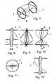
- Fig. 2shows a plan view in which the upper edge of the airfoil 1 and the tubular casing 4 is clearly visible.
- the airfoil 1can also be understood as two partial airfoils which extend radially from the hub 2 to the tubular support means 4 and extend axially helically.
- Fig. 3shows the rotor from the Fig. 1 in a side view, wherein the closed tubular or tubular shell 4 can be seen and the projecting beyond these ends of the hub second
- Fig. 4shows a broken view of the rotor Fig. 3 , wherein the edge regions of the airfoil 1, where it is connected to the sheath / support means 4, are shown in dashed lines.
- Fig. 5shows a longitudinal section through the rotor Fig. 1 , wherein at the upper end of the rotor, the blade 1 cuts the plane of the drawing.
- the airfoilcan, as in Fig. 5 and also in the following Fig. 6 represented, be made in one piece with the formed as a collapsible tube or as a collapsible tube support means 4.
- Thiscan for example consist of a plastic as a flexible hose and expanded by the pumping effect due to the pressure built up in its interior and kept dimensionally stable.
- the dimensional stabilitycan also be produced by the elastic restoring forces of the material.
- the bladesare expanded and brought into the ready form with the expansion movement.
- the blade 1, for example,is stretched between the support 4 and the hub 2 in the expanded state by train and thus well stabilized.
- FIG. 7shows an embodiment with two rings 6, 7, which together form the support means and support the airfoil 1.
- the support areas of the airfoil 1lie radially its extreme edge.
- the rings 6, 7may consist of a shape memory alloy, such as Nitinol, and be selectively expanded after insertion into a body to assume the illustrated circular shape. At the same time they pull the support areas of the airfoil 1 radially outward and tension this.
- a shape memory alloysuch as Nitinol
- Fig. 8shows a longitudinal section through the rotor according to FIGS. 7 and 9 the course of the edge of the airfoil in a side view.
- Fig. 10shows a three-dimensional side view, which makes the helical structure of the airfoil 1 clear.
- the rings 6, 7can also consist of an elastic material, for example a rubber-like material, which has low restoring forces when transported to the place of use in compressed form and stabilizes itself after taking the circular ring shape.
- the Fig. 11shows an axial plan view of the rotor according to Fig. 7 and the Fig. 12 a section in which the blade 1 cuts the plane of the drawing at the top and bottom of the rotor.
- the airfoilpasses through 180 degrees of helix between the upper and lower ends of the rotor.
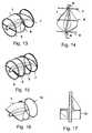
- a rotor of a fluid pumpwhich has a support device with three rings 6, 7, 8, which are each seen radially in the edge region of the airfoil 1 connected thereto and spaced from each other by means not shown struts.
- Fig. 14shows a side view of the rotor Fig. 13 .
- Fig. 15is a rotor with four rings 6, 7, 8, 9 shown in perspective, which together form the essential part form a support device. Incidentally, the same applies to the rings 6, 7, 8, 9 to those already described embodiments.
- the torquecan be introduced into the rotor via the support device.
- a part of the support meansmust be connected, for example via struts with a drive device or a drive shaft. This coupling will be discussed in more detail below.
- the torquecan also be introduced via the hub 2, if one is present.
- the effect of the support meansis limited to the radial support and shaping of the airfoil (s).
- Fig. 16shows an embodiment in three-dimensional representation, in which an airfoil 1 is stabilized at its periphery by a pipe section 10 and a hose section.
- Fig. 17shows the same arrangement in a longitudinal section.
- the pipe section 10may for example consist of a plastic and be made in one piece with the airfoil, but also of a different material of the airfoil material, such as a shape memory alloy.
- a hose or pipe sectionhas the disadvantage over a ring, possibly more difficult to compress, but the advantage of being more easily stabilized in expanded form.
- Fig. 18shows in three-dimensional view a rotor of a fluid pump with a rotor blade 1, which is supported by a support means 11 in the form of a continuous hose member.
- the hose member 11extends over the full axial length of the airfoil. However, the hose member may also be axially shorter than the airfoil. 1
- Fig. 19shows a longitudinal section through the embodiment Fig. 18 , wherein in particular three annular reinforcing elements 12, 13, 14 can be seen, which are fixed radially on the outside of the hose member 11 or made integrally with this.
- the reinforcing elements 12, 13, 14may be made of the same material as the hose member 11, but also from another, tends to be more rigid A material, such as a shape memory alloy of a rubber, which may tend to be stiffer than the flexible material of which the hose member 11 consists.
- the hose element 11can be at least partially mitexpandiert by expansion of the annular reinforcing elements 12, 13, 14 during the deployment.
- This expansion movementcan also be reinforced by an overpressure built up in the rotor as soon as the rotor is set in rotation.
- Fig. 20shows a side view of the rotor Fig. 18, 19 in closed form.
- annular reinforcing elements 12 ', 13', 14 'are meander-shaped in the circumferential direction.
- These reinforcing elementscan consist of a shape-memory material and are easy to fold, in particular due to the meander-shaped design.
- these reinforcing elementsmay also have a sawtooth structure or a wave line structure.
- Such reinforcing elementscan be glued, for example, on the hose member.
- Fig. 22shows a three-dimensional view of a hose member 15 which forms a support means for the paddle wheel 1 and is reinforced on its outer side by a wire mesh 16.
- the wire mesh 16may be glued, for example, on the hose member 15, in particular only selectively.
- the wire meshcan, as in Stents common, be designed so that a radial compression does not lead to a change in the length of the wire mesh element.
- the wire meshmay consist of a shape memory alloy as a metal wire or as, in particular one-piece, lattice structure, but also a production of a plastic is conceivable.
- the Fig. 23shows an embodiment of a rotor with two blades 1 ', 1 ", each attached to its outer side helically in a tubular member 15, for example, are glued, wherein the two helical shapes are coordinated so that the two blades 1', 1" at Compression of the support means 15 can slide past each other radially with respect to the axis of rotation, so that a substantial compression of the rotor as a whole is possible.
- Both vanes 1 ', 1"terminate radially at a distance from the axis of rotation, wherein a hub is not present At the edge of the blades close to the axis of rotation, only small forces act on them due to the fluid to be delivered, since the relative movement in this region close to the axis is small.
- the space saved by the omission of the hubcan be used in addition to the transport of the fluid, and the absence of the hub and the collapsibility of the blades make possible a substantial compression of the rotor in the radial direction.
- Fig. 24shows the embodiment Fig. 23 in a longitudinal section.
- tubular casingthat supports the support forms for the airfoils, an inner flexible shell and an outer mesh.
- FIGS. 25-29in particular show the coupling of the support means to two shaft journals which are provided on both sides of the rotor and can serve both a storage and the introduction of a torque.
- Fig. 25shows in a longitudinal sectional view of a tubular support means 17, which is connected via struts 18,19,20,21 with two shaft journals 22, 23. Since the airfoil 1 is supported by the support means 17, the entire rotor is rotatably supported and driven via the shaft journals 22, 23.
- Fig. 26shows a rotated about the rotation axis 24 by 90 ° representation in a side view.
- Fig. 27shows a view from the same direction as Fig. 26 in a sectional view.
- FIGS. 28, 29show the object of the FIGS. 25, 26, 27 each a three-dimensional representation, wherein the Fig. 28 an outside view shows while Fig. 29 shows a partially broken view, in which within the support means 17, the airfoil 1 is visible.
- FIGS. 28, 29show in contrast to the FIGS. 25, 26, 27 as a connection between the support means 17 and the shaft journals 22, 23 not fork-shaped struts 18, 19, but a triangular plate 25.
- Thishas over two bifurcated struts the advantage of being more stable, however, the disadvantage that during a rotational movement with high rotational frequency, the fluid must be displaced by the plate 25.
- Fig. 30shows a support means in which from the tubular member 17 in the shaft journal 22 by means of a triangular plate 25, the torque is transmitted.
- Fig. 31shows the same constellation in a partially broken representation.
- Fig. 33shows the same constellation as Fig. 32 in a longitudinal section.
- the FIGS. 32 and 33make it clear that there the torque is introduced directly into the airfoil 1 and that the support means 17 only serves to stabilize the airfoil / blades radially in the outer region or for expansion of the airfoil and for subsequent shape stabilization.
- the continuation of the helical structure 26 to the shaft journal 22also has the advantage that this is also at Rotation causes little resistance in the surrounding fluid, as it represents a continuation of the helical structure of the airfoil.
Landscapes
- Engineering & Computer Science (AREA)
- Health & Medical Sciences (AREA)
- Heart & Thoracic Surgery (AREA)
- Mechanical Engineering (AREA)
- Life Sciences & Earth Sciences (AREA)
- Anesthesiology (AREA)
- Biomedical Technology (AREA)
- Hematology (AREA)
- Animal Behavior & Ethology (AREA)
- General Health & Medical Sciences (AREA)
- Public Health (AREA)
- Veterinary Medicine (AREA)
- Cardiology (AREA)
- General Engineering & Computer Science (AREA)
- Vascular Medicine (AREA)
- Structures Of Non-Positive Displacement Pumps (AREA)
- External Artificial Organs (AREA)
Abstract
Description
Translated fromGermanDie Erfindung liegt auf dem Gebiet des Maschinenbaus, insbesondere der Mikromechanik, und befasst sich mit Fluidpumpen, die mit rotierenden Schaufelblättern arbeiten und besonders zum Einsatz in schwierig zugänglichen Bereichen eingerichtet sind.The invention is in the field of mechanical engineering, in particular micromechanics, and deals with fluid pumps which work with rotating blades and are particularly adapted for use in difficult to access areas.
Derartige Pumpen können beispielsweise im medizinischen Bereich eingesetzt werden und zu diesem Zweck auch besonders kleine Bauformen aufweisen.Such pumps can be used for example in the medical field and for this purpose also have particularly small designs.
Eine besondere Anwendung von Mikropumpen ist beispielsweise die Unterstützung der Pumpkraft des menschlichen Herzens. Pumpen, die in diesem Bereich eingesetzt werden, werden üblicherweise durch Blutgefäße in den Körper eingeführt und gegebenenfalls in einer Herzkammer betrieben.A particular application of micropumps is, for example, the support of the pumping power of the human heart. Pumps used in this area are usually introduced into the body through blood vessels and optionally operated in a ventricle.
Es ist eine Vielzahl solcher Pumpen bereits bekannt geworden, die verschiedenste Bauformen aufweisen. Aus der
Derartige Pumpen haben den Nachteil, dass sie einen im Verhältnis zur Pumpleistung großen Durchmesser aufweisen und kaum durch ein Blutgefäß einzuführen sind.Such pumps have the disadvantage that they have a large diameter in relation to the pumping capacity and can hardly be introduced through a blood vessel.
Im Gegensatz dazu ist aus der
Andere bekannt gewordene Rotoren weisen ebenfalls Schaufelblätter auf, die zum Betrieb entfaltbar sind, beispielsweise durch Gelenke oder durch elastische Verformbarkeit der Schaufelblätter.Other known rotors also have airfoils which are deployable for operation, for example by joints or by elastic deformability of the airfoils.
Ein besonderes Problem ist hierbei, dass die Schaufelblätter üblicherweise an einer zentrischen Nabe befestigt und von dieser aus rotatorisch antreibbar und auch beweglich schwenkbar sind, dass die Schaufelblätter somit flexibel sein, jedoch andererseits eine gewisse Steifigkeit bzw. eine Begrenzung ihrer Beweglichkeit aufweisen müssen, um den notwendigen Druck auf das Fluid zur Förderung auszuüben.A particular problem here is that the blades are usually attached to a central hub and from this rotationally drivable and movable so that the blades are thus flexible, but on the other hand must have some rigidity or a limitation of their mobility to the exert the necessary pressure on the fluid to promote.
Diese Aufgabe wurde im Stand der Technik bisher noch nicht optimal gelöst. Der vorliegenden Erfindung liegt daher die Aufgabe zugrunde, eine Pumpe der beschriebenen Art weiterzuentwickeln, um trotz eines im komprimierten Zustand geringen Pumpendurchmessers im Betrieb eine gute Pumpleistung zu erreichen. Die Konstruktion soll
dabei möglichst unaufwendig und kostengünstig sein.This task has not yet been optimally solved in the prior art. The present invention is therefore based on the object to further develop a pump of the type described in order to achieve a good pump performance despite a small pump diameter in the compressed state during operation. The construction should
be as inexpensive and inexpensive as possible.
Die Aufgabe wird gemäß der Erfindung mit den Merkmalen des Patentanspruchs 1 gelöst.The object is achieved according to the invention with the features of
Dabei ist wenigstens ein Schaufelblatt vorgesehen, das um eine Rotationsachse drehbar ist, um Fluid zu fördern, sowie eine Stützeinrichtung, die das wenigstens eine Schaufelblatt in einem Stützbereich stützt. Die Stützeinrichtung ist zudem zwischen einem komprimierten Rotorzustand und einem expandierten Rotorzustand veränderbar, und wenigstens ein Teil wenigstens eines Schaufelblattes erstreckt sich im expandierten Rotorzustand wenigstens teilweise vom Stützbereich aus gesehen radial nach innen auf die Rotorachse hin. Dadurch, dass der Stützbereich nicht am radial inneren Ende des Schaufelblattes liegt, sondern zum Schaufelradäußeren radial betrachtet versetzt ist, wird das Schaufelblatt/werden die Schaufelblätter in einem Bereich gestützt, in dem die Relativgeschwindigkeit zum Fluid größer ist als im Bereich der Rotationsachse und gegebenenfalls die mechanische Belastung des Schaufelblattes entsprechend stärker ist. Der Stützbereich und die Stützeinrichtung kann der einzige Bereich sein, in dem das Schaufelblatt /die Schaufelblätter gelagert oder mit einem anderen Bauteil verbunden oder zumindest der einzige Bereich, indem es/sie mittels der Stützeinrichtung mit anderen Bauteilen kraftübertragend verbunden ist/sind. Dabei kann der Fluid fördernde Bereich des Schaufelblattes / der Schaufelblätter ganz oder nur teilweise radial innerhalb des Stützbereiches liegen. Jedenfalls wird hier an die Stützeinrichtung und ihre Verbindung zu dem jeweiligen Schaufelblatt eine geringere mechanische Anforderung gestellt, als wenn die Stützeinrichtung die Schaufelblätter im Bereich der Rotationsachse stützen würde. Die Schaufelblätter können zudem schwächer ausgeführt werden, da sie in einem Bereich höherer Belastung gestützt werden und der mittlere Abstand der Fluid fördernden Bereiche des Schaufelblattes / der Schaufelblätter, in radialer Richtung betrachtet, vom Stützbereich geringer ist, als wenn dieses/diese im Bereich einer Nabe auf der Rotationsachse gestützt wäre(n).In this case, at least one airfoil is provided, which is rotatable about an axis of rotation in order to convey fluid, and a support device which supports the at least one airfoil in a support region. The support means is also variable between a compressed rotor state and an expanded rotor state, and at least a part of at least one airfoil extends in the expanded rotor state at least partially from the support region radially inwardly towards the rotor axis. Because the support region is not located at the radially inner end of the airfoil, but is radially offset relative to the outer side of the airfoil, the airfoil (s) is supported in a region in which the relative velocity to the fluid is greater than in the region of the axis of rotation and optionally the mechanical load on the blade is correspondingly stronger. The support region and the support means may be the only region in which the airfoil (s) are supported or connected to another component or at least the single region by force transmitting to other components by means of the support means is / are. In this case, the fluid-promoting region of the airfoil / of the airfoils can lie completely or only partially radially within the support region. In any case, a lower mechanical requirement is placed on the support device and its connection to the respective airfoil, as if the support means would support the airfoils in the region of the axis of rotation. The blades can also be made weaker, since they are supported in a region of higher load and the average distance of the fluid-conveying areas of the airfoil / blades, viewed in the radial direction, from the support area is lower than if this / these in the region of a hub supported on the axis of rotation would be (n).
Es kann auch vorgesehen sein, dass sich der überwiegende Teil des Fluid fördernden Bereiches des Schaufelblattes / der Schaufelblätter radial innerhalb des Stützbereiches / der Stützbereiche erstreckt. Damit ist der Stützbereich den sich am schnellsten bewegenden Teilen des Schaufelblattes / der Schaufelblätter am nächsten und kann diese effizient stützen, beispielsweise ein Drehmoment auf diese übertragen.It can also be provided that the predominant part of the fluid-conveying region of the blade airfoil (s) extends radially within the support region (s). Thus, the support area is closest to the fastest moving parts of the airfoil / vanes and can support them efficiently, for example, transmit torque to them.
Vorteilhaft kann auch vorgesehen sein, dass der Stützbereich radial außen am Umfang des Fluid führenden Bereiches des Schaufelblattes / der Schaufelblätter angeordnet ist. Dabei kann der Stützbereich die Schaufelblätter vollständig radial außen umgeben.Advantageously, it can also be provided that the support region is arranged radially outside on the circumference of the fluid-carrying region of the airfoil / of the airfoils. In this case, the support region can completely surround the airfoils radially on the outside.
Grundsätzlich kann das Schaufelblatt mit der Stützeinrichtung fest verbunden sein, so dass diese mit dem Schaufelblatt rotiert.In principle, the airfoil can be fixedly connected to the support device so that it rotates with the airfoil.
Dies ist eine Bauform, die besonders einfach herzustellen und mechanisch stabil ist. Die Stützeinrichtung kann beispielsweise aus demselben Material bestehen wie das Schaufelblatt und einstückig mit diesem hergestellt sein.This is a design that is particularly easy to manufacture and mechanically stable. The support means may for example consist of the same material as the airfoil and be made in one piece with this.
Es kann jedoch auch vorgesehen sein, dass die Stützeinrichtung aus einem anderen Material hergestellt ist als das Schaufelblatt, beispielsweise aus einer superelastischen Verbindung bzw. einem Formgedächtnismaterial, insbesondere Nitinol, so dass die Stützeinrichtung vor dem Übergang in den Betriebszustand aktiv in eine Betriebsgestalt übergehen kann, um damit den Rotor mit den Schaufelblättern aufzurichten, damit an die Schaufelblätter keine weiteren Anforderungen in Bezug auf eine selbsttätige Verformung gestellt werden. Diese können dann als dünne, nicht selbsttragende biegeschlaffe Folien hergestellt sein.However, it can also be provided that the support device is made of a different material than the airfoil, for example of a superelastic compound or a shape memory material, in particular Nitinol, so that the support device can actively transition into an operating state before the transition to the operating state, in order to erect the rotor with the blades, so that no further requirements with respect to an automatic deformation are placed on the blades. These can then be produced as thin, non-self-supporting, pliable films.
Das wenigstens eine Schaufelblatt kann jedoch auch beweglich gegenüber der Stützeinrichtung geführt und gelagert sein. Dann kann die Stützeinrichtung als Stator gegenüber den Schaufelblättern stillstehen. Es ist dann eine Führung beispielsweise in Form einer mechanischen oder magnetischen Lagerung der Schaufelblätter gegenüber der Stützeinrichtung notwendig.However, the at least one airfoil can also be movably guided and supported relative to the support device. Then the support device can stand as a stator relative to the blades. It is then a guide, for example in the form of a mechanical or magnetic bearing of the blades against the support necessary.
Die Stützeinrichtung kann beispielsweise durch wenigstens einen zur Rotationsachse konzentrisch positionierten und gegebenenfalls gelagerten Ring gebildet sein. Dieser Ring kann eine axiale Länge aufweisen, die geringer als die axiale Länge der Schaufelblätter ist.The support device can be formed, for example, by at least one ring positioned concentrically to the axis of rotation and possibly mounted. This ring may have an axial length that is less than the axial length of the airfoils.
Es können auch zwei oder mehr solche Ringe axial voneinander beabstandet jeweils mit dem Schaufelblatt / den Schaufelblättern verbunden sein. Die Ringe können beispielsweise in Umfangsrichtung mäanderförmig ausgestaltet sein, um eine entsprechende Verformbarkeit beispielsweise infolge von Superelastizität bzw. Formgedächtniseigenschaften besonders einfach realisieren zu können. Mehrere Ringe sind vorzugsweise koaxial zueinander angeordnet.It is also possible for two or more such rings to be axially spaced from each other with the airfoil / be connected to the blades. The rings may, for example, be configured meandering in the circumferential direction in order to be able to realize a corresponding deformability particularly easily, for example as a result of superelasticity or shape memory properties. Several rings are preferably arranged coaxially with each other.
Die Stützeinrichtung kann jedoch auch durch einen das Schaufelblatt / die Schaufelblätter umgebenden flexiblen Schlauch gebildet sein. Ein solcher Schlauch kann selbst aus einem Formgedächtnismaterial bestehen, beispielsweise auch aus einem Maschendrahtgeflecht aus Nitinoldraht, oder er kann aus einem für das Fluid undurchlässigen flexiblen organischen Material bestehen und Stützelemente wie beispielsweise Stützringe aufweisen. Der Schlauch kann im Pumpbetrieb durch Überdruck infolge des aufgebauten Fluiddrucks aufblasbar sein.However, the support means may also be formed by a flexible tube surrounding the airfoil / airfoils. Such a tube may itself consist of a shape memory material, for example also of a mesh wire mesh of nitinol wire, or it may consist of a fluid impermeable flexible organic material and support elements such as support rings. The hose can be inflated in the pumping operation by overpressure due to the built-up fluid pressure.
Der Schlauch kann punktuell oder streckenweise mit den äußeren Enden des Schaufelblattes / der Schaufelblätter verbunden sein.The tube can be connected at certain points or in sections with the outer ends of the airfoil / blades.
Gemäß der vorliegenden Erfindung benötigt der Rotor im Bereich der Schaufelblätter keine Nabe, so dass das Schaufelblatt / die Schaufelblätter radial mit allen seinen / ihren Teilen von der Rotationsachse beabstandet sein kann / können. In diesem Fall steht der ansonsten durch eine Nabe beanspruchte Querschnitt des Rotors zusätzlich zur Förderung von Fluid zur Verfügung.According to the present invention, the rotor does not need a hub in the region of the airfoils so that the airfoil (s) can be radially spaced with all its parts from the axis of rotation. In this case, the otherwise claimed by a hub cross-section of the rotor in addition to the promotion of fluid is available.
Wenn sich die Stützeinrichtung mit dem Schaufelblatt / den Schaufelblättern dreht, so kann sie kann in wenigstens einem Rotationslager gelagert sein, das axial außerhalb des Bereiches angeordnet ist, über den sich das Schaufelblatt / die Schaufelblätter erstreckt / erstrecken.When the support device rotates with the airfoil (s), it may be supported in at least one rotary bearing that is disposed axially outside the region over which the airfoil / blades extend / extend.
Diese Konstruktion ermöglicht eine einfache Lagerung in einem handelsüblichen Rotationslager, beispielsweise einem Wälzlager oder einem magnetischen Lager. Eine solche Lagerung ist weniger aufwendig und reibungsärmer als eine Lagerung am
Umfang der Stützeinrichtung im Bereich der Schaufelblätter.This construction allows easy storage in a commercial rotary bearing, such as a rolling bearing or a magnetic bearing. Such storage is less expensive and less friction than storage on
Scope of the support device in the area of the blades.
Es kann aber auch eine beispielsweise hydrodynamische Lagerung am Umfang der Stützeinrichtung vorgesehen sein, wenn ein Rotor der beschriebenen Art in einem Gehäuse läuft, und zwischen dem Gehäuse und der Stützeinrichtung ein Spalt vorgesehen ist, in dem sich ein Fluid befindet. In einer besonders einfachen Ausführung könnte dieses Fluid mit dem geförderten Fluid identisch sein.But it may also be provided, for example, a hydrodynamic bearing on the periphery of the support means when a rotor of the type described in a housing runs, and between the housing and the support means, a gap is provided, in which there is a fluid. In a particularly simple embodiment, this fluid could be identical to the delivered fluid.
Im Folgenden wird die Erfindung anhand eines Ausführungsbeispiels in einer Zeichnung gezeigt und anschließend beschrieben. Dabei zeigt
- Fig. 1
- eine dreidimensionale, teilweise durch- brochene Ansicht eines Rotors einer Fluidpumpe mit einer Stützeinrichtung und einem Schaufelblatt,
- Fig. 2
- eine axiale Draufsicht auf den Gegen- stand aus
Fig. 1 , - Fig. 3
- eine Seitenansicht,
- Fig. 4
- eine teilweise durchbrochene Seiten- ansicht des Gegenstandes aus
Fig. 1 , - Fign. 5 & 6
- jeweils Längsschnitte des Gegenstandes aus
Fig. 1 , - Fig. 7
- einen Rotor mit einer aus zwei Ringen bestehenden Stützeinrichtung und einem Schaufelblatt in dreidimensionaler An- sicht,
- Fig. 8
- den Gegenstand aus
Fig. 7 in einem Längsschnitt, - Fig. 9
- den Gegenstand aus
Fig. 7 in einer ersten Seitenansicht, - Fig. 10
- den Gegenstand aus
Fig. 7 in einer zweiten Seitenansicht, - Fig. 11
- den Gegenstand aus
Fig. 7 in einer axialen Draufsicht, - Fig. 12
- den Gegenstand aus
Fig. 7 in einem gegenüber dem Längsschnitt ausFig. 8 winkelmäßig versetzten Längsschnitt, - Fig. 13
- einen Rotor mit einer aus drei Ringen bestehenden Stützeinrichtung,
- Fig. 14
- eine Seitenansicht des Rotors aus
Fig. 13 , - Fig. 15
- einen Rotor mit einer vier Ringe auf- weisenden Stützeinrichtung in drei- dimensionaler Ansicht,
- Fig. 16
- einen Rotor, bei dem die Stützeinrich- tung aus mindestens einem Schlauchstück besteht,
- Fig. 17
- einen Längsschnitt des Gegenstandes aus
Fig. 16 , - Fig. 18
- einen Rotor, bei dem das Schaufelblatt / die Schaufelblätter zur Gänze von einer schlauchartigen Stützeinrichtung umgeben sind, wobei Verstärkungsringe den Schlauch verstärken,
- Fig. 19
- den Rotor aus
Fig. 18 in einem Längs- schnitt, - Fig. 20
- den Rotor aus
Fig. 18 in einer Seiten- ansicht, - Fig. 21
- den Rotor aus
Fig. 18 in einer drei- dimensionalen Ansicht, wobei die Stütz- ringe in Umfangsrichtung mäanderförmig gestaltet sind, - Fig. 22
- einen Rotor mit einer schlauchartigen Stützeinrichtung, die durch ein Maschendrahtgeflecht verstärkt ist, in dreidimensionaler Ansicht,
- Fig. 23
- einen Rotor ähnlich dem aus
Fig. 22 , wobei zwei Rotorblätter ohne eine Nabe derart angeordnet sind, dass sie nicht bis zur Rotationsachse reichen und beim Komprimieren des Rotors aneinander vor- beigleiten können, - Fig. 24
- die Anordnung aus
Fig. 23 in einem Längsschnitt, - Fig. 25
- eine Rotoranordnung mit einem Schaufel- blatt, das von einer schlauchartigen Stützeinrichtung umgeben ist, wobei die Stützeinrichtung mittels gabelförmiger Streben beiderseits an je einen Wellen- zapfen angeschlossen ist,
- Fig. 26
- eine Seitenansicht des Gegenstandes aus
Fig. 25 , - Fig. 27
- eine teilweise durchbrochene Ansicht des Gegenstandes aus
Fig. 26 , - Fig. 28
- eine dreidimensionale Außenansicht des Gegenstandes aus den
Fign. 25-27 , - Fig. 29
- eine teilweise durchbrochene dreidimen- sionale Ansicht des Gegenstandes aus
Fig. 28 , - Fig. 30
- einen Rotor mit einer schlauchförmigen Stützeinrichtung, die über eine Strebe an einen Wellenzapfen angeschlossen ist, wobei ein einziges Schaufelblatt vorgesehen ist,
- Fig. 31
- die Anordnung aus
Fig. 30 in teilweise durchbrochener Ansicht, - Fig. 32
- eine Ausgestaltung ähnlich der Kon- struktion aus
Fig. 30 , wobei das Schau- felblatt direkt und nicht über die Stützeinrichtung an den Wellenzapfen angekoppelt ist, - Fig. 33
- die Konstruktion aus
Fig. 32 in einem Längsschnitt.
- Fig. 1
- 3 is a three-dimensional, partially broken-away view of a rotor of a fluid pump with a support device and an airfoil,
- Fig. 2
- an axial plan view of the object from
Fig. 1 . - Fig. 3
- a side view,
- Fig. 4
- a partially open side view of the object
Fig. 1 . - FIGS. 5 & 6
- each longitudinal sections of the article
Fig. 1 . - Fig. 7
- a rotor with a support consisting of two rings and an airfoil in three-dimensional view,
- Fig. 8
- the object out
Fig. 7 in a longitudinal section, - Fig. 9
- the object out
Fig. 7 in a first side view, - Fig. 10
- the object out
Fig. 7 in a second side view, - Fig. 11
- the object out
Fig. 7 in an axial plan view, - Fig. 12
- the object out
Fig. 7 in one opposite the longitudinal sectionFig. 8 angularly offset longitudinal section, - Fig. 13
- a rotor having a support structure consisting of three rings,
- Fig. 14
- a side view of the rotor
Fig. 13 . - Fig. 15
- a rotor with a four-ring support device in three dimensional view,
- Fig. 16
- a rotor in which the support device consists of at least one piece of hose,
- Fig. 17
- a longitudinal section of the article
Fig. 16 . - Fig. 18
- a rotor in which the airfoil / vanes are entirely surrounded by a tubular support means, reinforcing rings reinforcing the hose,
- Fig. 19
- off the rotor
Fig. 18 in a longitudinal section, - Fig. 20
- off the rotor
Fig. 18 in a side view, - Fig. 21
- off the rotor
Fig. 18 in a three-dimensional view, with the support rings being meander-shaped in the circumferential direction, - Fig. 22
- a rotor with a hose-like support device, which is reinforced by a wire mesh, in three-dimensional view,
- Fig. 23
- a rotor similar to that
Fig. 22 in which two rotor blades without a hub are arranged in such a way that they do not reach up to the axis of rotation and when the rotor is compressed against one another. can accompany - Fig. 24
- the arrangement
Fig. 23 in a longitudinal section, - Fig. 25
- a rotor arrangement with a blade leaf, which is surrounded by a tube-like support device, wherein the support device is connected by means of fork-shaped struts on both sides to a respective shaft journal,
- Fig. 26
- a side view of the object
Fig. 25 . - Fig. 27
- a partially open view of the object
Fig. 26 . - Fig. 28
- a three-dimensional exterior view of the object of the
FIGS. 25-27 . - Fig. 29
- a partially open three-dimensional view of the object
Fig. 28 . - Fig. 30
- a rotor having a tubular support means connected by a strut to a shaft journal, wherein a single airfoil is provided,
- Fig. 31
- the arrangement
Fig. 30 in a partially broken view, - Fig. 32
- an embodiment similar to the construction of
Fig. 30 where the show leaf directly and is not coupled via the support means to the shaft journal, - Fig. 33
- the construction
Fig. 32 in a longitudinal section.
Die Nabe 2 ist üblicherweise mit einer antreibbaren Welle verbunden, die durch den Hohlkatheter und ein Blutgefäß zu einem Motorantrieb verläuft, der üblicherweise außerhalb des Körpers angeordnet sein kann. Zwischen dem Motorantrieb und dem Hohlkatheter ist eine Schleuse vorgesehen.The
Das Schaufelblatt 1 kann auch als zwei Teilschaufelblätter aufgefasst werden, die sich radial jeweils von der Nabe 2 zur schlauchförmigen Stützeinrichtung 4 hin erstrecken und axial wendelförmig verlaufen.The
Das Schaufelblatt kann, wie in
Aus der
Die Ringe 6, 7 können aus einer Formgedächtnislegierung, beispielsweise Nitinol, bestehen und nach dem Einführen in einen Körper gezielt expandiert werden, um die dargestellte Kreisform anzunehmen. Gleichzeitig ziehen sie die Stützbereiche des Schaufelblattes 1 radial nach außen und spannen dieses.The
Es können zusätzlich zu den dargestellten Elementen noch Abstandshalter zwischen den Ringen 6, 7 vorgesehen sein, die nicht formveränderlich sein müssen und ihre Gestalt beim Übergang zwischen der komprimierten und der expandierten Form des Rotors behalten können. Diese können als parallel zur Nabe 2 verlaufende Stangen bzw. Streben ausgebildet sein.It may be provided in addition to the illustrated elements nor spacers between the
Grundsätzlich können die Ringe 6, 7 auch aus einem elastischen Material, beispielsweise gummiartigen Material bestehen, das beim Transport zum Einsatzort in komprimierter Form geringe Rückstellkräfte aufweist und sich nach Einnahme der Kreisringform selbst stabilisiert.In principle, the
Die
In der
In der
einer Stützeinrichtung bilden. Im Übrigen gilt für die Ringe 6, 7, 8, 9 das zu den oben beschriebenen Ausführungsformen bereits Ausgeführte.In the
form a support device. Incidentally, the same applies to the
Grundsätzlich kann das Drehmoment in den Rotor über die Stützeinrichtung eingebracht werden. Dazu muss ein Teil der Stützeinrichtung beispielsweise über Streben mit einer Antriebseinrichtung bzw. einer Antriebswelle verbunden sein. Auf diese Ankopplung wird weiter unten noch genauer eingegangen.In principle, the torque can be introduced into the rotor via the support device. For this purpose, a part of the support means must be connected, for example via struts with a drive device or a drive shaft. This coupling will be discussed in more detail below.
Alternativ kann das Drehmoment auch über die Nabe 2 eingebracht werden, sofern eine solche vorhanden ist. In diesem Fall beschränkt sich die Wirkung der Stützeinrichtung auf die radiale Stützung und Formgebung des Schaufelblattes / der Schaufelblätter.Alternatively, the torque can also be introduced via the
Der Rohrabschnitt 10 kann beispielsweise aus einem Kunststoff bestehen und einstückig mit dem Schaufelblatt hergestellt sein, jedoch auch aus einem vom Material des Schaufelblattes unterschiedlichen Material, beispielsweise einer Formgedächtnislegierung. Ein derartiger Schlauch- oder Rohrabschnitt hat gegenüber einem Ring den Nachteil, möglicherweise schwieriger komprimierbar zu sein, jedoch den Vorteil, in sich in expandierter Form leichter stabilisierbar zu sein.The
Die Verstärkungselemente 12, 13, 14 können aus demselben Material bestehen wie das Schlauchelement 11, jedoch auch aus einem anderen, tendenziell steiferen Material, beispielsweise aus einer Formgedächtnislegierung aus einem Gummi, das tendenziell steifer sein kann als das flexible Material, aus dem das Schlauchelement 11 besteht.The reinforcing
Insofern kann bei der Entfaltung das Schlauchelement 11 durch Expansion der ringförmigen Verstärkungselemente 12, 13, 14 zumindest teilweise mitexpandiert werden. Diese Expansionsbewegung kann zudem durch einen in dem Rotor aufgebauten Überdruck verstärkt werden, sobald der Rotor in Rotation versetzt wird.In this respect, the
In der
Derartige Verstärkungselemente können beispielsweise auf das Schlauchelement aufgeklebt sein.Such reinforcing elements can be glued, for example, on the hose member.
Die
Beide Schaufelblätter 1', 1" enden radial mit Abstand von der Rotationsachse, wobei eine Nabe nicht vorhanden ist. An dem rotationsachsennahen Rand der Schaufelblätter wirken nur geringe Kräfte auf diese durch das zu fördernde Fluid, da die Relativbewegung in diesem achsennahen Bereich gering ist. Der durch das Weglassen der Nabe eingesparte Raum kann zusätzlich zum Transport des Fluids genutzt werden, und das Fehlen der Nabe sowie die Zusammenschiebbarkeit der Schaufelblätter macht eine weitgehende Kompression des Rotors in radialer Richtung möglich.Both
Ähnlich wie bei der Gestaltung aus
Die
Die
Die
Aus der
Die
Im Gegensatz dazu zeigt
Rotation wenig Widerstand in dem umgebenden Fluid hervorruft, da es eine Fortsetzung der wendelförmigen Struktur des Schaufelblattes darstellt.
Rotation causes little resistance in the surrounding fluid, as it represents a continuation of the helical structure of the airfoil.
Anhand der oben beschriebenen Beispiele wurde verdeutlicht, dass mit den Mitteln der Erfindung durch die Stützung von einem oder mehreren Schaufelblättern radial in deren Außenbereich mit geringem Aufwand eine hohe Stabilisierung der Schaufelblätter erreicht wird. Die Verbindung von Schaufelblättern mit einer Nabe wird dadurch entweder nicht besonders beansprucht oder sie wird insgesamt unnötig, was auch zum Entfallen der Nabe führen kann. Die Stützeinrichtung kann zudem bei der Expansion des Rotors das Schaufelblatt / die Schaufelblätter mitexpandieren, so dass diese aus handelsüblichen flexiblen Materialien ohne besonders hohe mechanische Anforderungen hergestellt werden können.From the examples described above, it was clarified that with the means of the invention the support of one or more blades radially in the outer region with little effort a high stabilization of the blades is achieved. The connection of blades with a hub is thereby either not particularly stressed or it is unnecessary altogether, which can also lead to elimination of the hub. The support device can also expand with the expansion of the rotor, the airfoil / the blades, so that they can be made of commercially available flexible materials without particularly high mechanical requirements.
Claims (15)
Translated fromGerman(4,6,7,8,9,10,12,12',13,13',14,14',15,17), die das wenigstens eine Schaufelblatt in wenigstens einem Stützbereich stützt, wobei die Stützeinrichtung zwischen einem ersten Zustand, in dem der Rotor radial komprimiert ist, und einem zweiten Zustand, in dem der Rotor radial expandiert ist, veränderbar ist und wobei sich wenigstens ein Schaufelblatt im radial expandierten Zustand des Rotors wenigstens teilweise in Bezug auf die Rotationsachse (3) von dem Stützbereich / den Stützbereichen aus radial nach innen erstreckt.Fluid pump with at least one airfoil (1,1 ', 1 ") which is rotatable about a rotation axis (3) and in operation promotes a fluid and with a support means
(4,6,7,8,9,10,12,12 ', 13,13', 14,14 ', 15,17), which supports the at least one airfoil in at least one support area, wherein the support means between a first State in which the rotor is radially compressed, and a second state in which the rotor is radially expanded, is variable and wherein at least one airfoil in the radially expanded state of the rotor at least partially with respect to the axis of rotation (3) from the support region / extends the support areas from radially inward.
(4,6,7,8,9,10,12,12',13,13',14,14',15,17) geführt und gelagert ist.Fluid pump according to claim 1, 2 or 3,characterized in that the at least one airfoil (1,1 ', 1 ") movable relative to the support means
(4,6,7,8,9,10,12,12 ', 13,13', 14,14 ', 15,17) is guided and stored.
(6,7,8,9,12,12',13,13',14,14',) gebildet ist.Fluid pump according to one of claims 1 to 5,characterized in that the support means by at least one concentric to the axis of rotation ring
(6,7,8,9,12,12 ', 13,13', 14,14 ',) is formed.
(4,6,7,8,9,10.12.12',13,13',14,14',15,17) in wenigstens einem Rotationslager gelagert ist, das / die axial außerhalb des Bereiches angeordnet ist / sind, in dem sich das Schaufelblatt / die Schaufelblätter erstreckt / erstrecken.Fluid pump according to claim 1 or one of the following,characterized in that the support means
(4,6,7,8,9,10.12.12 ', 13,13', 14,14 ', 15,17) is mounted in at least one rotary bearing, which / is arranged axially outside of the area, are in where the airfoil (s) extend.
Priority Applications (9)
| Application Number | Priority Date | Filing Date | Title |
|---|---|---|---|
| EP09075441AEP2298373A1 (en) | 2009-09-22 | 2009-09-22 | Fluid pump with at least one turbine blade and a seating device |
| DE112010003745TDE112010003745T5 (en) | 2009-09-22 | 2010-09-22 | Fluid pump with at least one airfoil and a support means |
| US13/261,205US9089634B2 (en) | 2009-09-22 | 2010-09-22 | Fluid pump having at least one impeller blade and a support device |
| CN201080042123.1ACN102655891B (en) | 2009-09-22 | 2010-09-22 | Fluid pump with at least one impeller blade and support |
| PCT/EP2010/005867WO2011035927A1 (en) | 2009-09-22 | 2010-09-22 | Fluid pump having at least one impeller blade and a support device |
| US14/807,615US10208763B2 (en) | 2009-09-22 | 2015-07-23 | Fluid pump having at least one impeller blade and a support device |
| US16/243,855US11592028B2 (en) | 2009-09-22 | 2019-01-09 | Fluid pump having at least one impeller blade and a support device |
| US18/098,761US12066030B2 (en) | 2009-09-22 | 2023-01-19 | Fluid pump having at least one impeller blade and a support device |
| US18/773,050US20250012290A1 (en) | 2009-09-22 | 2024-07-15 | Fluid pump having at least one impeller blade and a support device |
Applications Claiming Priority (1)
| Application Number | Priority Date | Filing Date | Title |
|---|---|---|---|
| EP09075441AEP2298373A1 (en) | 2009-09-22 | 2009-09-22 | Fluid pump with at least one turbine blade and a seating device |
Publications (1)
| Publication Number | Publication Date |
|---|---|
| EP2298373A1true EP2298373A1 (en) | 2011-03-23 |
Family
ID=41667412
Family Applications (1)
| Application Number | Title | Priority Date | Filing Date |
|---|---|---|---|
| EP09075441AWithdrawnEP2298373A1 (en) | 2009-09-22 | 2009-09-22 | Fluid pump with at least one turbine blade and a seating device |
Country Status (5)
| Country | Link |
|---|---|
| US (5) | US9089634B2 (en) |
| EP (1) | EP2298373A1 (en) |
| CN (1) | CN102655891B (en) |
| DE (1) | DE112010003745T5 (en) |
| WO (1) | WO2011035927A1 (en) |
Cited By (12)
| Publication number | Priority date | Publication date | Assignee | Title |
|---|---|---|---|---|
| US10722631B2 (en) | 2018-02-01 | 2020-07-28 | Shifamed Holdings, Llc | Intravascular blood pumps and methods of use and manufacture |
| US11185677B2 (en) | 2017-06-07 | 2021-11-30 | Shifamed Holdings, Llc | Intravascular fluid movement devices, systems, and methods of use |
| US11511103B2 (en) | 2017-11-13 | 2022-11-29 | Shifamed Holdings, Llc | Intravascular fluid movement devices, systems, and methods of use |
| US11654275B2 (en) | 2019-07-22 | 2023-05-23 | Shifamed Holdings, Llc | Intravascular blood pumps with struts and methods of use and manufacture |
| US11724089B2 (en) | 2019-09-25 | 2023-08-15 | Shifamed Holdings, Llc | Intravascular blood pump systems and methods of use and control thereof |
| US11964145B2 (en) | 2019-07-12 | 2024-04-23 | Shifamed Holdings, Llc | Intravascular blood pumps and methods of manufacture and use |
| WO2024153205A1 (en)* | 2023-01-18 | 2024-07-25 | 上海魅丽纬叶医疗科技有限公司 | Foldable composite rotating blades and medical power pump |
| US12102815B2 (en) | 2019-09-25 | 2024-10-01 | Shifamed Holdings, Llc | Catheter blood pumps and collapsible pump housings |
| US12121713B2 (en) | 2019-09-25 | 2024-10-22 | Shifamed Holdings, Llc | Catheter blood pumps and collapsible blood conduits |
| US12161857B2 (en) | 2018-07-31 | 2024-12-10 | Shifamed Holdings, Llc | Intravascular blood pumps and methods of use |
| US12220570B2 (en) | 2018-10-05 | 2025-02-11 | Shifamed Holdings, Llc | Intravascular blood pumps and methods of use |
| US12409310B2 (en) | 2019-12-11 | 2025-09-09 | Shifamed Holdings, Llc | Descending aorta and vena cava blood pumps |
Families Citing this family (98)
| Publication number | Priority date | Publication date | Assignee | Title |
|---|---|---|---|---|
| US7393181B2 (en) | 2004-09-17 | 2008-07-01 | The Penn State Research Foundation | Expandable impeller pump |
| CN102380135A (en) | 2006-03-23 | 2012-03-21 | 宾州研究基金会 | Heart assist device with expandable impeller pump |
| HUE055876T2 (en)* | 2008-10-10 | 2021-12-28 | Medicaltree Patent Ltd | Heart help pump |
| EP2194278A1 (en) | 2008-12-05 | 2010-06-09 | ECP Entwicklungsgesellschaft mbH | Fluid pump with a rotor |
| EP2216059A1 (en) | 2009-02-04 | 2010-08-11 | ECP Entwicklungsgesellschaft mbH | Catheter device with a catheter and an actuation device |
| EP2229965A1 (en) | 2009-03-18 | 2010-09-22 | ECP Entwicklungsgesellschaft mbH | Fluid pump with particular form of a rotor blade |
| EP2246078A1 (en) | 2009-04-29 | 2010-11-03 | ECP Entwicklungsgesellschaft mbH | Shaft assembly with a shaft which moves within a fluid-filled casing |
| EP2248544A1 (en) | 2009-05-05 | 2010-11-10 | ECP Entwicklungsgesellschaft mbH | Fluid pump with variable circumference, particularly for medical use |
| EP2266640A1 (en) | 2009-06-25 | 2010-12-29 | ECP Entwicklungsgesellschaft mbH | Compressible and expandable turbine blade for a fluid pump |
| EP2282070B1 (en) | 2009-08-06 | 2012-10-17 | ECP Entwicklungsgesellschaft mbH | Catheter device with a coupling device for a drive device |
| EP2298371A1 (en) | 2009-09-22 | 2011-03-23 | ECP Entwicklungsgesellschaft mbH | Function element, in particular fluid pump with a housing and a transport element |
| EP2298373A1 (en) | 2009-09-22 | 2011-03-23 | ECP Entwicklungsgesellschaft mbH | Fluid pump with at least one turbine blade and a seating device |
| EP2298372A1 (en) | 2009-09-22 | 2011-03-23 | ECP Entwicklungsgesellschaft mbH | Rotor for an axial pump for transporting a fluid |
| EP2299119B1 (en) | 2009-09-22 | 2018-11-07 | ECP Entwicklungsgesellschaft mbH | Inflatable rotor for a fluid pump |
| EP2314330A1 (en) | 2009-10-23 | 2011-04-27 | ECP Entwicklungsgesellschaft mbH | Flexible shaft arrangement |
| EP2314331B1 (en) | 2009-10-23 | 2013-12-11 | ECP Entwicklungsgesellschaft mbH | Catheter pump arrangement and flexible shaft arrangement with a cable core |
| EP2338541A1 (en) | 2009-12-23 | 2011-06-29 | ECP Entwicklungsgesellschaft mbH | Radial compressible and expandable rotor for a fluid pump |
| EP2338540A1 (en) | 2009-12-23 | 2011-06-29 | ECP Entwicklungsgesellschaft mbH | Delivery blade for a compressible rotor |
| EP2338539A1 (en) | 2009-12-23 | 2011-06-29 | ECP Entwicklungsgesellschaft mbH | Pump device with a detection device |
| EP2347778A1 (en) | 2010-01-25 | 2011-07-27 | ECP Entwicklungsgesellschaft mbH | Fluid pump with a radially compressible rotor |
| EP2363157A1 (en) | 2010-03-05 | 2011-09-07 | ECP Entwicklungsgesellschaft mbH | Device for exerting mechanical force on a medium, in particular fluid pump |
| EP2388029A1 (en) | 2010-05-17 | 2011-11-23 | ECP Entwicklungsgesellschaft mbH | Pump array |
| EP2399639A1 (en) | 2010-06-25 | 2011-12-28 | ECP Entwicklungsgesellschaft mbH | System for introducing a pump |
| EP2407186A1 (en) | 2010-07-15 | 2012-01-18 | ECP Entwicklungsgesellschaft mbH | Rotor for a pump, produced with an initial elastic material |
| EP2407187A3 (en) | 2010-07-15 | 2012-06-20 | ECP Entwicklungsgesellschaft mbH | Blood pump for invasive application within the body of a patient |
| EP2407185A1 (en) | 2010-07-15 | 2012-01-18 | ECP Entwicklungsgesellschaft mbH | Radial compressible and expandable rotor for a pump with a turbine blade |
| EP2422735A1 (en) | 2010-08-27 | 2012-02-29 | ECP Entwicklungsgesellschaft mbH | Implantable blood transportation device, manipulation device and coupling device |
| WO2012094641A2 (en) | 2011-01-06 | 2012-07-12 | Thoratec Corporation | Percutaneous heart pump |
| EP2497521A1 (en) | 2011-03-10 | 2012-09-12 | ECP Entwicklungsgesellschaft mbH | Push device for axial insertion of a string-shaped, flexible body |
| US9162017B2 (en)* | 2011-08-29 | 2015-10-20 | Minnetronix, Inc. | Expandable vascular pump |
| EP2564771A1 (en) | 2011-09-05 | 2013-03-06 | ECP Entwicklungsgesellschaft mbH | Medicinal product with a functional element for invasive use in the body of a patient |
| US8926492B2 (en) | 2011-10-11 | 2015-01-06 | Ecp Entwicklungsgesellschaft Mbh | Housing for a functional element |
| EP4218887A1 (en) | 2012-05-14 | 2023-08-02 | Tc1 Llc | Mechanical circulatory support device for stabilizing a patient after cardiogenic shock |
| US8721517B2 (en) | 2012-05-14 | 2014-05-13 | Thoratec Corporation | Impeller for catheter pump |
| US9872947B2 (en) | 2012-05-14 | 2018-01-23 | Tc1 Llc | Sheath system for catheter pump |
| US9446179B2 (en) | 2012-05-14 | 2016-09-20 | Thoratec Corporation | Distal bearing support |
| US9327067B2 (en) | 2012-05-14 | 2016-05-03 | Thoratec Corporation | Impeller for catheter pump |
| CN108742951B (en) | 2012-06-06 | 2021-05-25 | 洋红医疗有限公司 | Artificial kidney valve |
| EP4186557A1 (en) | 2012-07-03 | 2023-05-31 | Tc1 Llc | Motor assembly for catheter pump |
| US9421311B2 (en) | 2012-07-03 | 2016-08-23 | Thoratec Corporation | Motor assembly for catheter pump |
| US9358329B2 (en) | 2012-07-03 | 2016-06-07 | Thoratec Corporation | Catheter pump |
| US20140100310A1 (en) | 2012-10-08 | 2014-04-10 | Teknor Apex Company | Thermoplastic elastomer compositions having biorenewable content |
| US11077294B2 (en) | 2013-03-13 | 2021-08-03 | Tc1 Llc | Sheath assembly for catheter pump |
| WO2014164136A1 (en) | 2013-03-13 | 2014-10-09 | Thoratec Corporation | Fluid handling system |
| US10583231B2 (en) | 2013-03-13 | 2020-03-10 | Magenta Medical Ltd. | Blood pump |
| US11033728B2 (en) | 2013-03-13 | 2021-06-15 | Tc1 Llc | Fluid handling system |
| EP4233702A3 (en) | 2013-03-13 | 2023-12-20 | Magenta Medical Ltd. | Manufacture of an impeller |
| EP4190376A1 (en) | 2013-03-15 | 2023-06-07 | Tc1 Llc | Catheter pump assembly including a stator |
| US9308302B2 (en) | 2013-03-15 | 2016-04-12 | Thoratec Corporation | Catheter pump assembly including a stator |
| US9764113B2 (en) | 2013-12-11 | 2017-09-19 | Magenta Medical Ltd | Curved catheter |
| US10583232B2 (en) | 2014-04-15 | 2020-03-10 | Tc1 Llc | Catheter pump with off-set motor position |
| EP3131599B1 (en) | 2014-04-15 | 2019-02-20 | Tc1 Llc | Catheter pump with access ports |
| EP3131597B1 (en) | 2014-04-15 | 2020-12-02 | Tc1 Llc | Catheter pump introducer systems |
| WO2015160943A1 (en) | 2014-04-15 | 2015-10-22 | Thoratec Corporation | Sensors for catheter pumps |
| EP3583973A1 (en) | 2014-08-18 | 2019-12-25 | Tc1 Llc | Guide features for percutaneous catheter pump |
| US9770543B2 (en) | 2015-01-22 | 2017-09-26 | Tc1 Llc | Reduced rotational mass motor assembly for catheter pump |
| WO2016118781A2 (en) | 2015-01-22 | 2016-07-28 | Thoratec Corporation | Motor assembly with heat exchanger for catheter pump |
| US9675738B2 (en) | 2015-01-22 | 2017-06-13 | Tc1 Llc | Attachment mechanisms for motor of catheter pump |
| USD767112S1 (en)* | 2015-04-15 | 2016-09-20 | K&N Engineering, Inc. | Vent breather |
| US9907890B2 (en) | 2015-04-16 | 2018-03-06 | Tc1 Llc | Catheter pump with positioning brace |
| WO2016185473A1 (en) | 2015-05-18 | 2016-11-24 | Magenta Medical Ltd. | Blood pump |
| EP4548956A3 (en)* | 2015-08-04 | 2025-08-06 | Abiomed Europe GmbH | Blood pump with self-flushing bearing |
| EP3808401A1 (en) | 2016-07-21 | 2021-04-21 | Tc1 Llc | Gas-filled chamber for catheter pump motor assembly |
| US11160970B2 (en) | 2016-07-21 | 2021-11-02 | Tc1 Llc | Fluid seals for catheter pump motor assembly |
| EP3518825B1 (en) | 2016-09-29 | 2020-05-27 | Magenta Medical Ltd. | Blood vessel tube |
| CA3039285A1 (en) | 2016-10-25 | 2018-05-03 | Magenta Medical Ltd. | Ventricular assist device |
| US10179197B2 (en)* | 2016-11-21 | 2019-01-15 | Cardiobridge Gmbh | Catheter pump with a pump head for insertion into the aorta |
| JP7094279B2 (en) | 2016-11-23 | 2022-07-01 | マジェンタ・メディカル・リミテッド | Blood pump |
| US20180172020A1 (en)* | 2016-12-15 | 2018-06-21 | Saudi Arabian Oil Company | Wellbore tools including smart materials |
| RU2650457C1 (en)* | 2017-01-18 | 2018-04-13 | ООО "Научно-производственное объединение Челнинский насосный завод" | Impeller and compressor stage guide of the submerged centrifugal pump |
| FR3071282B1 (en) | 2017-09-21 | 2022-04-08 | Fineheart | INTERNAL BLADE TURBINE |
| US10905808B2 (en) | 2018-01-10 | 2021-02-02 | Magenta Medical Ltd. | Drive cable for use with a blood pump |
| EP3638336B1 (en) | 2018-01-10 | 2022-04-06 | Magenta Medical Ltd. | Ventricular assist device |
| DE102018201030B4 (en) | 2018-01-24 | 2025-10-16 | Kardion Gmbh | Magnetic dome element with magnetic bearing function |
| US10893927B2 (en) | 2018-03-29 | 2021-01-19 | Magenta Medical Ltd. | Inferior vena cava blood-flow implant |
| DE102018207575A1 (en) | 2018-05-16 | 2019-11-21 | Kardion Gmbh | Magnetic face turning coupling for the transmission of torques |
| DE102018207611A1 (en) | 2018-05-16 | 2019-11-21 | Kardion Gmbh | Rotor bearing system |
| DE102018208550A1 (en) | 2018-05-30 | 2019-12-05 | Kardion Gmbh | A lead device for directing blood flow to a cardiac assist system, cardiac assist system, and method of making a lead device |
| DE102018208538A1 (en) | 2018-05-30 | 2019-12-05 | Kardion Gmbh | Intravascular blood pump and process for the production of electrical conductors |
| DE102018208541A1 (en) | 2018-05-30 | 2019-12-05 | Kardion Gmbh | Axial pump for a cardiac assist system and method of making an axial pump for a cardiac assist system |
| DE102018208539A1 (en) | 2018-05-30 | 2019-12-05 | Kardion Gmbh | A motor housing module for sealing an engine compartment of a motor of a cardiac assist system and cardiac assistance system and method for mounting a cardiac assist system |
| US10668195B2 (en) | 2018-06-01 | 2020-06-02 | Fbr Medical, Inc. | Catheter pump with fixed-diameter impeller |
| DE102018210076A1 (en) | 2018-06-21 | 2019-12-24 | Kardion Gmbh | Method and device for detecting a state of wear of a cardiac support system, method and device for operating a cardiac support system and cardiac support system |
| DE102018210058A1 (en) | 2018-06-21 | 2019-12-24 | Kardion Gmbh | Stator blade device for guiding the flow of a fluid flowing out of an outlet opening of a heart support system, heart support system with stator blade device, method for operating a stator blade device and manufacturing method |
| DE102018211327A1 (en) | 2018-07-10 | 2020-01-16 | Kardion Gmbh | Impeller for an implantable vascular support system |
| DE102018212153A1 (en) | 2018-07-20 | 2020-01-23 | Kardion Gmbh | Inlet line for a pump unit of a cardiac support system, cardiac support system and method for producing an inlet line for a pump unit of a cardiac support system |
| US11541224B2 (en) | 2018-07-30 | 2023-01-03 | Cardiovascular Systems, Inc. | Intravascular pump without inducer and centrifugal force-driven expansion of impeller blades and/or expandable and collapsible impeller housing |
| CN112654389A (en) | 2018-08-07 | 2021-04-13 | 开迪恩有限公司 | Bearing device for a cardiac support system and method for flushing an intermediate space in a bearing device for a cardiac support system |
| CN111166949A (en)* | 2018-11-13 | 2020-05-19 | 上海微创医疗器械(集团)有限公司 | Impeller, method for manufacturing impeller, and percutaneous blood pump |
| AU2020211431B2 (en) | 2019-01-24 | 2024-10-24 | Magenta Medical Ltd | Ventricular assist device |
| EP3972661B1 (en) | 2019-05-23 | 2024-09-11 | Magenta Medical Ltd. | Blood pumps |
| CN113123972B (en) | 2019-12-31 | 2023-06-06 | 丹佛斯(天津)有限公司 | Oil pump and scroll compressor |
| DE102020102474A1 (en) | 2020-01-31 | 2021-08-05 | Kardion Gmbh | Pump for conveying a fluid and method for manufacturing a pump |
| EP3984589B1 (en) | 2020-04-07 | 2023-08-23 | Magenta Medical Ltd. | Magnetic phase sensing |
| WO2024057257A2 (en)* | 2022-09-14 | 2024-03-21 | Magenta Medical Ltd | Pump-head portion of ventricular assist device |
| CN116317290A (en)* | 2022-09-20 | 2023-06-23 | 安徽通灵仿生科技有限公司 | Catheter pump motor |
| CN119327028B (en)* | 2024-10-28 | 2025-08-01 | 同济大学 | Micro pump head |
| CN120384890B (en)* | 2025-06-30 | 2025-09-26 | 成都永益泵业股份有限公司 | Slurry pump impeller and manufacturing method thereof |
Citations (7)
| Publication number | Priority date | Publication date | Assignee | Title |
|---|---|---|---|---|
| US4969865A (en)* | 1989-01-09 | 1990-11-13 | American Biomed, Inc. | Helifoil pump |
| WO1998053864A1 (en) | 1997-05-30 | 1998-12-03 | Cardinove Inc. | Ventricular assist device comprising an enclosed-impeller axial flow blood pump |
| WO2003103745A2 (en) | 2002-06-11 | 2003-12-18 | Walid Aboul-Hosn | Expandable blood pump and related methods |
| US20060008349A1 (en)* | 2004-05-20 | 2006-01-12 | Kenneth Khaw | Replaceable expandable transmyocardial ventricular assist device |
| EP1738783A1 (en) | 2005-07-01 | 2007-01-03 | Universitätsspital Basel | Axial flow pump with helical blade |
| WO2007112033A2 (en)* | 2006-03-23 | 2007-10-04 | The Penn State Research Foundation | Heart assist device with expandable impeller pump |
| EP2047872A1 (en)* | 2007-10-08 | 2009-04-15 | Ais Gmbh Aachen Innovative Solutions | Catheter device |
Family Cites Families (136)
| Publication number | Priority date | Publication date | Assignee | Title |
|---|---|---|---|---|
| US3510229A (en) | 1968-07-23 | 1970-05-05 | Maytag Co | One-way pump |
| US3568659A (en) | 1968-09-24 | 1971-03-09 | James N Karnegis | Disposable percutaneous intracardiac pump and method of pumping blood |
| CH538410A (en)* | 1971-02-17 | 1973-06-30 | L Somers S Brice | Flexible device for the transport of granular, powdery or fluid products |
| US4014317A (en) | 1972-02-18 | 1977-03-29 | The United States Of America As Represented By The Department Of Health, Education And Welfare | Multipurpose cardiocirculatory assist cannula and methods of use thereof |
| US3812812A (en) | 1973-06-25 | 1974-05-28 | M Hurwitz | Trolling propeller with self adjusting hydrodynamic spoilers |
| US4207028A (en) | 1979-06-12 | 1980-06-10 | Ridder Sven O | Extendable and retractable propeller for watercraft |
| US4559951A (en) | 1982-11-29 | 1985-12-24 | Cardiac Pacemakers, Inc. | Catheter assembly |
| US4563181A (en) | 1983-02-18 | 1986-01-07 | Mallinckrodt, Inc. | Fused flexible tip catheter |
| US4686982A (en) | 1985-06-19 | 1987-08-18 | John Nash | Spiral wire bearing for rotating wire drive catheter |
| US4679558A (en) | 1985-08-12 | 1987-07-14 | Intravascular Surgical Instruments, Inc. | Catheter based surgical methods and apparatus therefor |
| US4801243A (en) | 1985-12-28 | 1989-01-31 | Bird-Johnson Company | Adjustable diameter screw propeller |
| US4747821A (en) | 1986-10-22 | 1988-05-31 | Intravascular Surgical Instruments, Inc. | Catheter with high speed moving working head |
| US4753221A (en) | 1986-10-22 | 1988-06-28 | Intravascular Surgical Instruments, Inc. | Blood pumping catheter and method of use |
| US4749376A (en) | 1986-10-24 | 1988-06-07 | Intravascular Surgical Instruments, Inc. | Reciprocating working head catheter |
| US4817613A (en) | 1987-07-13 | 1989-04-04 | Devices For Vascular Intervention, Inc. | Guiding catheter |
| US5154705A (en) | 1987-09-30 | 1992-10-13 | Lake Region Manufacturing Co., Inc. | Hollow lumen cable apparatus |
| US5061256A (en) | 1987-12-07 | 1991-10-29 | Johnson & Johnson | Inflow cannula for intravascular blood pumps |
| US5183384A (en) | 1988-05-16 | 1993-02-02 | Trumbly Joe H | Foldable propeller assembly |
| US5011469A (en) | 1988-08-29 | 1991-04-30 | Shiley, Inc. | Peripheral cardiopulmonary bypass and coronary reperfusion system |
| US4919647A (en) | 1988-10-13 | 1990-04-24 | Kensey Nash Corporation | Aortically located blood pumping catheter and method of use |
| US4957504A (en) | 1988-12-02 | 1990-09-18 | Chardack William M | Implantable blood pump |
| US5112292A (en) | 1989-01-09 | 1992-05-12 | American Biomed, Inc. | Helifoil pump |
| US5052404A (en) | 1989-03-02 | 1991-10-01 | The Microspring Company, Inc. | Torque transmitter |
| US4995857A (en) | 1989-04-07 | 1991-02-26 | Arnold John R | Left ventricular assist device and method for temporary and permanent procedures |
| US5042984A (en) | 1989-08-17 | 1991-08-27 | Kensey Nash Corporation | Catheter with working head having selectable impacting surfaces and method of using the same |
| US5097849A (en) | 1989-08-17 | 1992-03-24 | Kensey Nash Corporation | Method of use of catheter with working head having selectable impacting surfaces |
| US5040944A (en) | 1989-09-11 | 1991-08-20 | Cook Einar P | Pump having impeller rotational about convoluted stationary member |
| GB2239675A (en) | 1989-12-05 | 1991-07-10 | Man Fai Shiu | Pump for pumping liquid |
| US5118264A (en) | 1990-01-11 | 1992-06-02 | The Cleveland Clinic Foundation | Purge flow control in rotary blood pumps |
| US5145333A (en) | 1990-03-01 | 1992-09-08 | The Cleveland Clinic Foundation | Fluid motor driven blood pump |
| JPH0636821B2 (en) | 1990-03-08 | 1994-05-18 | 健二 山崎 | Implantable auxiliary artificial heart |
| US5108411A (en) | 1990-03-28 | 1992-04-28 | Cardiovascular Imaging Systems, Inc. | Flexible catheter drive cable |
| US5092844A (en) | 1990-04-10 | 1992-03-03 | Mayo Foundation For Medical Education And Research | Intracatheter perfusion pump apparatus and method |
| US5163910A (en) | 1990-04-10 | 1992-11-17 | Mayo Foundation For Medical Education And Research | Intracatheter perfusion pump apparatus and method |
| US5191888A (en) | 1990-04-18 | 1993-03-09 | Cordis Corporation | Assembly of an extension guidewire and an alignment tool for same |
| US5113872A (en) | 1990-04-18 | 1992-05-19 | Cordis Corporation | Guidewire extension system with connectors |
| US5813405A (en) | 1990-04-18 | 1998-09-29 | Cordis Corporation | Snap-in connection assembly for extension guidewire system |
| US5117838A (en) | 1990-04-18 | 1992-06-02 | Cordis Corporation | Rotating guidewire extension system |
| ES2020787A6 (en) | 1990-07-20 | 1991-09-16 | Figuera Aymerich Diego | Intra-ventricular expansible assist pump |
| US5192286A (en) | 1991-07-26 | 1993-03-09 | Regents Of The University Of California | Method and device for retrieving materials from body lumens |
| US5201679A (en) | 1991-12-13 | 1993-04-13 | Attwood Corporation | Marine propeller with breakaway hub |
| US6302910B1 (en) | 1992-06-23 | 2001-10-16 | Sun Medical Technology Research Corporation | Auxiliary artificial heart of an embedded type |
| US5300112A (en) | 1992-07-14 | 1994-04-05 | Aai Corporation | Articulated heart pump |
| US5676651A (en) | 1992-08-06 | 1997-10-14 | Electric Boat Corporation | Surgically implantable pump arrangement and method for pumping body fluids |
| SE501215C2 (en)* | 1992-09-02 | 1994-12-12 | Oeyvind Reitan | catheter Pump |
| US5376114A (en) | 1992-10-30 | 1994-12-27 | Jarvik; Robert | Cannula pumps for temporary cardiac support and methods of their application and use |
| US5368438A (en) | 1993-06-28 | 1994-11-29 | Baxter International Inc. | Blood pump |
| DK145093D0 (en) | 1993-12-23 | 1993-12-23 | Gori 1902 As | PROPELLER |
| US5531789A (en) | 1993-12-24 | 1996-07-02 | Sun Medical Technology Research Corporation | Sealing system of an artificial internal organ |
| DE19535781C2 (en) | 1995-09-26 | 1999-11-11 | Fraunhofer Ges Forschung | Device for active flow support of body fluids |
| US5701911A (en) | 1996-04-05 | 1997-12-30 | Medtronic, Inc. | Guide wire extension docking system |
| US6254359B1 (en) | 1996-05-10 | 2001-07-03 | The United States Of America As Represented By The Administrator Of The National Aeronautics And Space Administration | Method for providing a jewel bearing for supporting a pump rotor shaft |
| IL118352A0 (en) | 1996-05-21 | 1996-09-12 | Sudai Amnon | Apparatus and methods for revascularization |
| US5820571A (en) | 1996-06-24 | 1998-10-13 | C. R. Bard, Inc. | Medical backloading wire |
| US5779721A (en) | 1996-07-26 | 1998-07-14 | Kensey Nash Corporation | System and method of use for revascularizing stenotic bypass grafts and other blood vessels |
| US5851174A (en) | 1996-09-17 | 1998-12-22 | Robert Jarvik | Cardiac support device |
| US5882329A (en) | 1997-02-12 | 1999-03-16 | Prolifix Medical, Inc. | Apparatus and method for removing stenotic material from stents |
| US6129704A (en) | 1997-06-12 | 2000-10-10 | Schneider (Usa) Inc. | Perfusion balloon catheter having a magnetically driven impeller |
| DE29804046U1 (en) | 1998-03-07 | 1998-04-30 | Günther, Rolf W., Prof. Dr.med., 52074 Aachen | Percutaneously implantable, self-expanding axial pump for temporary heart support |
| US6308632B1 (en) | 1998-11-23 | 2001-10-30 | James E. Shaffer | Deployable folded propeller assembly for aerial projectiles |
| CA2256131A1 (en) | 1998-12-16 | 2000-06-16 | Micro Therapeutics, Inc. | Miniaturized medical brush |
| EP1034808A1 (en)* | 1999-03-09 | 2000-09-13 | Paul Frederik Gründeman | A device for transventricular mechanical circulatory support |
| DE20007581U1 (en) | 1999-04-20 | 2000-10-19 | Mediport Kardiotechnik GmbH, 12247 Berlin | Device for the axial conveyance of fluid media |
| US6458139B1 (en) | 1999-06-21 | 2002-10-01 | Endovascular Technologies, Inc. | Filter/emboli extractor for use in variable sized blood vessels |
| US6506025B1 (en) | 1999-06-23 | 2003-01-14 | California Institute Of Technology | Bladeless pump |
| US6398714B1 (en) | 1999-07-29 | 2002-06-04 | Intra-Vasc.Nl B.V. | Cardiac assist catheter pump and catheter and fitting for use therein |
| US7022100B1 (en) | 1999-09-03 | 2006-04-04 | A-Med Systems, Inc. | Guidable intravascular blood pump and related methods |
| JP2003510035A (en) | 1999-09-10 | 2003-03-18 | インサイト・ゲノミックス・インコーポレイテッド | Apoptotic protein |
| US6454775B1 (en) | 1999-12-06 | 2002-09-24 | Bacchus Vascular Inc. | Systems and methods for clot disruption and retrieval |
| JP2001207988A (en) | 2000-01-26 | 2001-08-03 | Nipro Corp | Magnetic driving type axial flow pump |
| US20010031981A1 (en)* | 2000-03-31 | 2001-10-18 | Evans Michael A. | Method and device for locating guidewire and treating chronic total occlusions |
| US6592612B1 (en) | 2000-05-04 | 2003-07-15 | Cardeon Corporation | Method and apparatus for providing heat exchange within a catheter body |
| US8034097B2 (en)* | 2000-05-22 | 2011-10-11 | Malte Neuss | Radially expandable vessel support |
| US6537030B1 (en) | 2000-10-18 | 2003-03-25 | Fasco Industries, Inc. | Single piece impeller having radial output |
| DE20119322U1 (en) | 2000-11-21 | 2002-02-21 | Schering Ag, 13353 Berlin | Tubular vascular grafts (stents) |
| DE10058669B4 (en) | 2000-11-25 | 2004-05-06 | Impella Cardiotechnik Ag | micromotor |
| DE10059714C1 (en) | 2000-12-01 | 2002-05-08 | Impella Cardiotech Ag | Intravasal pump has pump stage fitted with flexible expandible sleeve contricted during insertion through blood vessel |
| DE10108810A1 (en) | 2001-02-16 | 2002-08-29 | Berlin Heart Ag | Device for the axial conveyance of liquids |
| US6517315B2 (en) | 2001-05-29 | 2003-02-11 | Hewlett-Packard Company | Enhanced performance fan with the use of winglets |
| ITFO20010019A1 (en) | 2001-08-07 | 2003-02-07 | Gabriele Canestrini | SYSTEM AND MEANS FOR SELECTING DIFFERENT PRODUCTS AND RECYCLABLE WASTE. |
| US6981942B2 (en) | 2001-11-19 | 2006-01-03 | University Of Medicine And Dentristy Of New Jersey | Temporary blood circulation assist device |
| US20030231959A1 (en) | 2002-06-12 | 2003-12-18 | William Hackett | Impeller assembly for centrifugal pumps |
| US7118356B2 (en) | 2002-10-02 | 2006-10-10 | Nanyang Technological University | Fluid pump with a tubular driver body capable of selective axial expansion and contraction |
| US6860713B2 (en) | 2002-11-27 | 2005-03-01 | Nidec Corporation | Fan with collapsible blades, redundant fan system, and related method |
| US20040215222A1 (en) | 2003-04-25 | 2004-10-28 | Michael Krivoruchko | Intravascular material removal device |
| US7655022B2 (en) | 2003-04-28 | 2010-02-02 | Cardiac Pacemakers, Inc. | Compliant guiding catheter sheath system |
| US7074018B2 (en) | 2003-07-10 | 2006-07-11 | Sheldon Chang | Direct drive linear flow blood pump |
| DE10336902C5 (en) | 2003-08-08 | 2019-04-25 | Abiomed Europe Gmbh | Intracardiac pumping device |
| EP1670524A4 (en) | 2003-10-09 | 2012-12-26 | Thoratec Corp | Impeller |
| EP2151257B1 (en) | 2004-08-13 | 2013-04-17 | Delgado, Reynolds M., III | Apparatus for long-term assisting a left ventricle to pump blood |
| US7393181B2 (en) | 2004-09-17 | 2008-07-01 | The Penn State Research Foundation | Expandable impeller pump |
| DE102004054714A1 (en)* | 2004-11-12 | 2006-05-24 | Impella Cardiosystems Gmbh | Foldable intravascular insertable blood pump |
| US7479102B2 (en) | 2005-02-28 | 2009-01-20 | Robert Jarvik | Minimally invasive transvalvular ventricular assist device |
| AU2006255059A1 (en) | 2005-06-06 | 2006-12-14 | Foster-Miller, Inc. | Blood pump |
| DE102005052102A1 (en) | 2005-10-28 | 2007-05-03 | Boehringer Ingelheim Pharma Gmbh & Co. Kg | New beta-agonists, process for their preparation and their use as medicines |
| DE102006036948A1 (en) | 2006-08-06 | 2008-02-07 | Akdis, Mustafa, Dipl.-Ing. | blood pump |
| US9028392B2 (en)* | 2006-12-01 | 2015-05-12 | NuCardia, Inc. | Medical device |
| AU2008219653B2 (en) | 2007-02-26 | 2014-01-16 | Heartware, Inc. | Intravascular ventricular assist device |
| ES2605170T3 (en) | 2007-03-19 | 2017-03-13 | Boston Scientific Neuromodulation Corporation | Cable manufacturing procedures and apparatus with conductors and related flexible cable configurations |
| DE102007014224A1 (en) | 2007-03-24 | 2008-09-25 | Abiomed Europe Gmbh | Blood pump with micromotor |
| US7828710B2 (en) | 2007-06-05 | 2010-11-09 | Medical Value Partners, Llc | Apparatus comprising a drive cable for a medical device |
| JP5351401B2 (en)* | 2007-09-28 | 2013-11-27 | 三菱重工業株式会社 | Compressor |
| EP2047873B1 (en) | 2007-10-08 | 2010-12-15 | Ais Gmbh Aachen Innovative Solutions | Catheter device |
| US8489190B2 (en) | 2007-10-08 | 2013-07-16 | Ais Gmbh Aachen Innovative Solutions | Catheter device |
| US8439859B2 (en) | 2007-10-08 | 2013-05-14 | Ais Gmbh Aachen Innovative Solutions | Catheter device |
| EP2194278A1 (en) | 2008-12-05 | 2010-06-09 | ECP Entwicklungsgesellschaft mbH | Fluid pump with a rotor |
| EP2216059A1 (en) | 2009-02-04 | 2010-08-11 | ECP Entwicklungsgesellschaft mbH | Catheter device with a catheter and an actuation device |
| EP2218469B1 (en) | 2009-02-12 | 2012-10-31 | ECP Entwicklungsgesellschaft mbH | Casing for a functional element |
| EP2229965A1 (en) | 2009-03-18 | 2010-09-22 | ECP Entwicklungsgesellschaft mbH | Fluid pump with particular form of a rotor blade |
| EP2246078A1 (en) | 2009-04-29 | 2010-11-03 | ECP Entwicklungsgesellschaft mbH | Shaft assembly with a shaft which moves within a fluid-filled casing |
| EP2248544A1 (en) | 2009-05-05 | 2010-11-10 | ECP Entwicklungsgesellschaft mbH | Fluid pump with variable circumference, particularly for medical use |
| US8617239B2 (en) | 2009-05-18 | 2013-12-31 | Cardiobridge Gmbh | Catheter pump |
| EP2266640A1 (en) | 2009-06-25 | 2010-12-29 | ECP Entwicklungsgesellschaft mbH | Compressible and expandable turbine blade for a fluid pump |
| EP2282070B1 (en) | 2009-08-06 | 2012-10-17 | ECP Entwicklungsgesellschaft mbH | Catheter device with a coupling device for a drive device |
| EP2298372A1 (en) | 2009-09-22 | 2011-03-23 | ECP Entwicklungsgesellschaft mbH | Rotor for an axial pump for transporting a fluid |
| EP2298373A1 (en) | 2009-09-22 | 2011-03-23 | ECP Entwicklungsgesellschaft mbH | Fluid pump with at least one turbine blade and a seating device |
| EP2299119B1 (en) | 2009-09-22 | 2018-11-07 | ECP Entwicklungsgesellschaft mbH | Inflatable rotor for a fluid pump |
| EP2298371A1 (en) | 2009-09-22 | 2011-03-23 | ECP Entwicklungsgesellschaft mbH | Function element, in particular fluid pump with a housing and a transport element |
| EP2314331B1 (en) | 2009-10-23 | 2013-12-11 | ECP Entwicklungsgesellschaft mbH | Catheter pump arrangement and flexible shaft arrangement with a cable core |
| EP2314330A1 (en) | 2009-10-23 | 2011-04-27 | ECP Entwicklungsgesellschaft mbH | Flexible shaft arrangement |
| US8734508B2 (en)* | 2009-12-21 | 2014-05-27 | Boston Scientific Scimed, Inc. | Systems and methods for making and using percutaneously-delivered pumping systems for providing hemodynamic support |
| EP2338539A1 (en) | 2009-12-23 | 2011-06-29 | ECP Entwicklungsgesellschaft mbH | Pump device with a detection device |
| EP2338540A1 (en) | 2009-12-23 | 2011-06-29 | ECP Entwicklungsgesellschaft mbH | Delivery blade for a compressible rotor |
| EP2338541A1 (en) | 2009-12-23 | 2011-06-29 | ECP Entwicklungsgesellschaft mbH | Radial compressible and expandable rotor for a fluid pump |
| EP2347778A1 (en) | 2010-01-25 | 2011-07-27 | ECP Entwicklungsgesellschaft mbH | Fluid pump with a radially compressible rotor |
| EP2353626A1 (en) | 2010-01-27 | 2011-08-10 | ECP Entwicklungsgesellschaft mbH | Supply device for a fluid |
| EP2363157A1 (en) | 2010-03-05 | 2011-09-07 | ECP Entwicklungsgesellschaft mbH | Device for exerting mechanical force on a medium, in particular fluid pump |
| EP2388029A1 (en) | 2010-05-17 | 2011-11-23 | ECP Entwicklungsgesellschaft mbH | Pump array |
| EP2399639A1 (en) | 2010-06-25 | 2011-12-28 | ECP Entwicklungsgesellschaft mbH | System for introducing a pump |
| EP2407187A3 (en) | 2010-07-15 | 2012-06-20 | ECP Entwicklungsgesellschaft mbH | Blood pump for invasive application within the body of a patient |
| EP2407185A1 (en) | 2010-07-15 | 2012-01-18 | ECP Entwicklungsgesellschaft mbH | Radial compressible and expandable rotor for a pump with a turbine blade |
| EP2407186A1 (en) | 2010-07-15 | 2012-01-18 | ECP Entwicklungsgesellschaft mbH | Rotor for a pump, produced with an initial elastic material |
| EP2497521A1 (en) | 2011-03-10 | 2012-09-12 | ECP Entwicklungsgesellschaft mbH | Push device for axial insertion of a string-shaped, flexible body |
| US8734331B2 (en)* | 2011-08-29 | 2014-05-27 | Minnetronix, Inc. | Expandable blood pumps and methods of their deployment and use |
| WO2016185473A1 (en)* | 2015-05-18 | 2016-11-24 | Magenta Medical Ltd. | Blood pump |
| CN114432588B (en)* | 2022-01-18 | 2023-11-10 | 江苏大学 | An aortic puncture type axial flow blood pump with folded blade structure |
- 2009
- 2009-09-22EPEP09075441Apatent/EP2298373A1/ennot_activeWithdrawn
- 2010
- 2010-09-22USUS13/261,205patent/US9089634B2/enactiveActive
- 2010-09-22CNCN201080042123.1Apatent/CN102655891B/enactiveActive
- 2010-09-22DEDE112010003745Tpatent/DE112010003745T5/enactivePending
- 2010-09-22WOPCT/EP2010/005867patent/WO2011035927A1/enactiveApplication Filing
- 2015
- 2015-07-23USUS14/807,615patent/US10208763B2/enactiveActive
- 2019
- 2019-01-09USUS16/243,855patent/US11592028B2/enactiveActive
- 2023
- 2023-01-19USUS18/098,761patent/US12066030B2/enactiveActive
- 2024
- 2024-07-15USUS18/773,050patent/US20250012290A1/enactivePending
Patent Citations (7)
| Publication number | Priority date | Publication date | Assignee | Title |
|---|---|---|---|---|
| US4969865A (en)* | 1989-01-09 | 1990-11-13 | American Biomed, Inc. | Helifoil pump |
| WO1998053864A1 (en) | 1997-05-30 | 1998-12-03 | Cardinove Inc. | Ventricular assist device comprising an enclosed-impeller axial flow blood pump |
| WO2003103745A2 (en) | 2002-06-11 | 2003-12-18 | Walid Aboul-Hosn | Expandable blood pump and related methods |
| US20060008349A1 (en)* | 2004-05-20 | 2006-01-12 | Kenneth Khaw | Replaceable expandable transmyocardial ventricular assist device |
| EP1738783A1 (en) | 2005-07-01 | 2007-01-03 | Universitätsspital Basel | Axial flow pump with helical blade |
| WO2007112033A2 (en)* | 2006-03-23 | 2007-10-04 | The Penn State Research Foundation | Heart assist device with expandable impeller pump |
| EP2047872A1 (en)* | 2007-10-08 | 2009-04-15 | Ais Gmbh Aachen Innovative Solutions | Catheter device |
Cited By (15)
| Publication number | Priority date | Publication date | Assignee | Title |
|---|---|---|---|---|
| US11185677B2 (en) | 2017-06-07 | 2021-11-30 | Shifamed Holdings, Llc | Intravascular fluid movement devices, systems, and methods of use |
| US11717670B2 (en) | 2017-06-07 | 2023-08-08 | Shifamed Holdings, LLP | Intravascular fluid movement devices, systems, and methods of use |
| US11511103B2 (en) | 2017-11-13 | 2022-11-29 | Shifamed Holdings, Llc | Intravascular fluid movement devices, systems, and methods of use |
| US12076545B2 (en) | 2018-02-01 | 2024-09-03 | Shifamed Holdings, Llc | Intravascular blood pumps and methods of use and manufacture |
| US11229784B2 (en) | 2018-02-01 | 2022-01-25 | Shifamed Holdings, Llc | Intravascular blood pumps and methods of use and manufacture |
| US10722631B2 (en) | 2018-02-01 | 2020-07-28 | Shifamed Holdings, Llc | Intravascular blood pumps and methods of use and manufacture |
| US12161857B2 (en) | 2018-07-31 | 2024-12-10 | Shifamed Holdings, Llc | Intravascular blood pumps and methods of use |
| US12220570B2 (en) | 2018-10-05 | 2025-02-11 | Shifamed Holdings, Llc | Intravascular blood pumps and methods of use |
| US11964145B2 (en) | 2019-07-12 | 2024-04-23 | Shifamed Holdings, Llc | Intravascular blood pumps and methods of manufacture and use |
| US11654275B2 (en) | 2019-07-22 | 2023-05-23 | Shifamed Holdings, Llc | Intravascular blood pumps with struts and methods of use and manufacture |
| US11724089B2 (en) | 2019-09-25 | 2023-08-15 | Shifamed Holdings, Llc | Intravascular blood pump systems and methods of use and control thereof |
| US12102815B2 (en) | 2019-09-25 | 2024-10-01 | Shifamed Holdings, Llc | Catheter blood pumps and collapsible pump housings |
| US12121713B2 (en) | 2019-09-25 | 2024-10-22 | Shifamed Holdings, Llc | Catheter blood pumps and collapsible blood conduits |
| US12409310B2 (en) | 2019-12-11 | 2025-09-09 | Shifamed Holdings, Llc | Descending aorta and vena cava blood pumps |
| WO2024153205A1 (en)* | 2023-01-18 | 2024-07-25 | 上海魅丽纬叶医疗科技有限公司 | Foldable composite rotating blades and medical power pump |
Also Published As
| Publication number | Publication date |
|---|---|
| DE112010003745T5 (en) | 2013-02-28 |
| US11592028B2 (en) | 2023-02-28 |
| US10208763B2 (en) | 2019-02-19 |
| US9089634B2 (en) | 2015-07-28 |
| CN102655891A (en) | 2012-09-05 |
| US20190211836A1 (en) | 2019-07-11 |
| US20230235745A1 (en) | 2023-07-27 |
| US20120224970A1 (en) | 2012-09-06 |
| WO2011035927A1 (en) | 2011-03-31 |
| US20160053768A1 (en) | 2016-02-25 |
| CN102655891B (en) | 2015-08-19 |
| US12066030B2 (en) | 2024-08-20 |
| US20250012290A1 (en) | 2025-01-09 |
Similar Documents
| Publication | Publication Date | Title |
|---|---|---|
| EP2298373A1 (en) | Fluid pump with at least one turbine blade and a seating device | |
| DE112010003744B4 (en) | Rotor for an axial pump for conveying a fluid | |
| DE112012005415B4 (en) | Pump housing with an interior space for accommodating a pump rotor | |
| DE112010004977B4 (en) | Radially compressible and expandable rotor for a fluid pump | |
| DE112010002711B4 (en) | Compressible and expandable blade for a fluid pump | |
| EP3579904B1 (en) | Catheter pump comprising drive unit and catheter | |
| EP2338540A1 (en) | Delivery blade for a compressible rotor | |
| EP3393543B1 (en) | Catheter pump with pump head for introduction in arterial vessel system | |
| EP2248544A1 (en) | Fluid pump with variable circumference, particularly for medical use | |
| DE112011102347T5 (en) | Blood pump for invasive use within a patient's body | |
| EP2999496B1 (en) | Pump, in particular a blood pump | |
| EP2218469B1 (en) | Casing for a functional element | |
| EP2229965A1 (en) | Fluid pump with particular form of a rotor blade | |
| EP3441616B1 (en) | Compressible rotor for a fluid pump | |
| EP2343091B1 (en) | Fluid pump with a transport device with controllable volume alteration | |
| DE112011100345T5 (en) | Conveying device for a fluid | |
| DE112011102353T5 (en) | Radially compressible and expandable rotor for a pump with an airfoil | |
| EP2194278A1 (en) | Fluid pump with a rotor | |
| DE112011100328T5 (en) | Fluid pump with a radially compressible rotor | |
| DE202009018416U1 (en) | Diameter changeable fluid pump | |
| EP2298371A1 (en) | Function element, in particular fluid pump with a housing and a transport element | |
| DE112022001482T5 (en) | PUMP INCLUDING A COMPRESSIBLE ROTOR WITH OFFSET ROTOR BLADES | |
| DE102009059721A1 (en) | drive | |
| EP3088017A1 (en) | Rotor for a fluid pump and method and mould for its preparation |
Legal Events
| Date | Code | Title | Description |
|---|---|---|---|
| PUAI | Public reference made under article 153(3) epc to a published international application that has entered the european phase | Free format text:ORIGINAL CODE: 0009012 | |
| AK | Designated contracting states | Kind code of ref document:A1 Designated state(s):AT BE BG CH CY CZ DE DK EE ES FI FR GB GR HR HU IE IS IT LI LT LU LV MC MK MT NL NO PL PT RO SE SI SK SM TR | |
| AX | Request for extension of the european patent | Extension state:AL BA RS | |
| STAA | Information on the status of an ep patent application or granted ep patent | Free format text:STATUS: THE APPLICATION IS DEEMED TO BE WITHDRAWN | |
| 18D | Application deemed to be withdrawn | Effective date:20110924 |