EP2298372A1 - Rotor for an axial pump for transporting a fluid - Google Patents
Rotor for an axial pump for transporting a fluidDownload PDFInfo
- Publication number
- EP2298372A1 EP2298372A1EP09075440AEP09075440AEP2298372A1EP 2298372 A1EP2298372 A1EP 2298372A1EP 09075440 AEP09075440 AEP 09075440AEP 09075440 AEP09075440 AEP 09075440AEP 2298372 A1EP2298372 A1EP 2298372A1
- Authority
- EP
- European Patent Office
- Prior art keywords
- airfoil
- webs
- rotor according
- rotor
- blade
- Prior art date
- Legal status (The legal status is an assumption and is not a legal conclusion. Google has not performed a legal analysis and makes no representation as to the accuracy of the status listed.)
- Withdrawn
Links
Images


Classifications
- F—MECHANICAL ENGINEERING; LIGHTING; HEATING; WEAPONS; BLASTING
- F04—POSITIVE - DISPLACEMENT MACHINES FOR LIQUIDS; PUMPS FOR LIQUIDS OR ELASTIC FLUIDS
- F04D—NON-POSITIVE-DISPLACEMENT PUMPS
- F04D29/00—Details, component parts, or accessories
- F04D29/18—Rotors
- F04D29/181—Axial flow rotors
- A—HUMAN NECESSITIES
- A61—MEDICAL OR VETERINARY SCIENCE; HYGIENE
- A61M—DEVICES FOR INTRODUCING MEDIA INTO, OR ONTO, THE BODY; DEVICES FOR TRANSDUCING BODY MEDIA OR FOR TAKING MEDIA FROM THE BODY; DEVICES FOR PRODUCING OR ENDING SLEEP OR STUPOR
- A61M60/00—Blood pumps; Devices for mechanical circulatory actuation; Balloon pumps for circulatory assistance
- A61M60/10—Location thereof with respect to the patient's body
- A61M60/122—Implantable pumps or pumping devices, i.e. the blood being pumped inside the patient's body
- A61M60/126—Implantable pumps or pumping devices, i.e. the blood being pumped inside the patient's body implantable via, into, inside, in line, branching on, or around a blood vessel
- A61M60/13—Implantable pumps or pumping devices, i.e. the blood being pumped inside the patient's body implantable via, into, inside, in line, branching on, or around a blood vessel by means of a catheter allowing explantation, e.g. catheter pumps temporarily introduced via the vascular system
- A—HUMAN NECESSITIES
- A61—MEDICAL OR VETERINARY SCIENCE; HYGIENE
- A61M—DEVICES FOR INTRODUCING MEDIA INTO, OR ONTO, THE BODY; DEVICES FOR TRANSDUCING BODY MEDIA OR FOR TAKING MEDIA FROM THE BODY; DEVICES FOR PRODUCING OR ENDING SLEEP OR STUPOR
- A61M60/00—Blood pumps; Devices for mechanical circulatory actuation; Balloon pumps for circulatory assistance
- A61M60/20—Type thereof
- A61M60/205—Non-positive displacement blood pumps
- A61M60/216—Non-positive displacement blood pumps including a rotating member acting on the blood, e.g. impeller
- A61M60/237—Non-positive displacement blood pumps including a rotating member acting on the blood, e.g. impeller the blood flow through the rotating member having mainly axial components, e.g. axial flow pumps
- A—HUMAN NECESSITIES
- A61—MEDICAL OR VETERINARY SCIENCE; HYGIENE
- A61M—DEVICES FOR INTRODUCING MEDIA INTO, OR ONTO, THE BODY; DEVICES FOR TRANSDUCING BODY MEDIA OR FOR TAKING MEDIA FROM THE BODY; DEVICES FOR PRODUCING OR ENDING SLEEP OR STUPOR
- A61M60/00—Blood pumps; Devices for mechanical circulatory actuation; Balloon pumps for circulatory assistance
- A61M60/40—Details relating to driving
- A61M60/403—Details relating to driving for non-positive displacement blood pumps
- A61M60/408—Details relating to driving for non-positive displacement blood pumps the force acting on the blood contacting member being mechanical, e.g. transmitted by a shaft or cable
- A61M60/411—Details relating to driving for non-positive displacement blood pumps the force acting on the blood contacting member being mechanical, e.g. transmitted by a shaft or cable generated by an electromotor
- A61M60/414—Details relating to driving for non-positive displacement blood pumps the force acting on the blood contacting member being mechanical, e.g. transmitted by a shaft or cable generated by an electromotor transmitted by a rotating cable, e.g. for blood pumps mounted on a catheter
- A—HUMAN NECESSITIES
- A61—MEDICAL OR VETERINARY SCIENCE; HYGIENE
- A61M—DEVICES FOR INTRODUCING MEDIA INTO, OR ONTO, THE BODY; DEVICES FOR TRANSDUCING BODY MEDIA OR FOR TAKING MEDIA FROM THE BODY; DEVICES FOR PRODUCING OR ENDING SLEEP OR STUPOR
- A61M60/00—Blood pumps; Devices for mechanical circulatory actuation; Balloon pumps for circulatory assistance
- A61M60/80—Constructional details other than related to driving
- A61M60/802—Constructional details other than related to driving of non-positive displacement blood pumps
- A61M60/804—Impellers
- A61M60/806—Vanes or blades
- A61M60/808—Vanes or blades specially adapted for deformable impellers, e.g. expandable impellers
- A—HUMAN NECESSITIES
- A61—MEDICAL OR VETERINARY SCIENCE; HYGIENE
- A61M—DEVICES FOR INTRODUCING MEDIA INTO, OR ONTO, THE BODY; DEVICES FOR TRANSDUCING BODY MEDIA OR FOR TAKING MEDIA FROM THE BODY; DEVICES FOR PRODUCING OR ENDING SLEEP OR STUPOR
- A61M60/00—Blood pumps; Devices for mechanical circulatory actuation; Balloon pumps for circulatory assistance
- A61M60/80—Constructional details other than related to driving
- A61M60/802—Constructional details other than related to driving of non-positive displacement blood pumps
- A61M60/81—Pump housings
- F—MECHANICAL ENGINEERING; LIGHTING; HEATING; WEAPONS; BLASTING
- F04—POSITIVE - DISPLACEMENT MACHINES FOR LIQUIDS; PUMPS FOR LIQUIDS OR ELASTIC FLUIDS
- F04D—NON-POSITIVE-DISPLACEMENT PUMPS
- F04D29/00—Details, component parts, or accessories
- F04D29/18—Rotors
- F04D29/22—Rotors specially for centrifugal pumps
- F04D29/24—Vanes
- F04D29/247—Vanes elastic or self-adjusting
- A—HUMAN NECESSITIES
- A61—MEDICAL OR VETERINARY SCIENCE; HYGIENE
- A61M—DEVICES FOR INTRODUCING MEDIA INTO, OR ONTO, THE BODY; DEVICES FOR TRANSDUCING BODY MEDIA OR FOR TAKING MEDIA FROM THE BODY; DEVICES FOR PRODUCING OR ENDING SLEEP OR STUPOR
- A61M2205/00—General characteristics of the apparatus
- A61M2205/02—General characteristics of the apparatus characterised by a particular materials
- A61M2205/0266—Shape memory materials
- A—HUMAN NECESSITIES
- A61—MEDICAL OR VETERINARY SCIENCE; HYGIENE
- A61M—DEVICES FOR INTRODUCING MEDIA INTO, OR ONTO, THE BODY; DEVICES FOR TRANSDUCING BODY MEDIA OR FOR TAKING MEDIA FROM THE BODY; DEVICES FOR PRODUCING OR ENDING SLEEP OR STUPOR
- A61M60/00—Blood pumps; Devices for mechanical circulatory actuation; Balloon pumps for circulatory assistance
- A61M60/10—Location thereof with respect to the patient's body
- A61M60/122—Implantable pumps or pumping devices, i.e. the blood being pumped inside the patient's body
- A61M60/126—Implantable pumps or pumping devices, i.e. the blood being pumped inside the patient's body implantable via, into, inside, in line, branching on, or around a blood vessel
- A61M60/148—Implantable pumps or pumping devices, i.e. the blood being pumped inside the patient's body implantable via, into, inside, in line, branching on, or around a blood vessel in line with a blood vessel using resection or like techniques, e.g. permanent endovascular heart assist devices
Definitions
- the inventionis in the field of mechanical engineering, in particular precision engineering, and is of particular benefit in the medical field.
- the inventionrelates to a rotor for an axial pump.
- micropumpsare required for a variety of applications. These are used for micro-invasive applications, for example for the promotion of endogenous fluids in the body's own cavities or vessels.
- micro-invasive applicationsfor example for the promotion of endogenous fluids in the body's own cavities or vessels.
- cathetersare connected in micro design with catheters and introduced, for example, by the body's own vessels and brought to the site.
- heart pumpswhich are introduced into the body through a large blood vessel and can support or even replace the blood supply of the heart.
- rotary pumpshave become known in this context, which are designed as axial pumps.
- a special feature of some such pumpsin addition to their inherently small size, is the radial compressibility, so that such a pump can be compressed for transport through a blood vessel and expanded after it has been brought to the site, for example, in a heart chamber.
- Such a pumpis for example from the US patents US 2009/0060743 A1 and US 2008/0114339 A1 known.
- the axial pumps described in these documentseach have a shaft and flexible attached blade rows, which promote fluid in the axial direction upon rotation of the shaft.
- the bladesare radially to the shaft can be applied, so that in this way the rotor is compressible.
- the individual airfoilsalign, inter alia, by the fluid back pressure, so that the pump has a considerable delivery capacity.
- the present inventionis based on the background of the prior art the object to provide a rotor for an axial pump, which is as simple as possible and inexpensive to produce. He should also be low in mass and allow sufficient flow.
- the rotor according to the inventionhas an airfoil with at least one partial surface which extends transversely to the axis of rotation beyond the latter, wherein the airfoil has webs which individually or as a network connect different edge regions of the airfoil to one another.
- At least a partial surface of the airfoilis designed such that elements of the subarea face each other with respect to the axis of rotation at the same axial position on different sides of the axis of rotation.
- Thiscan for example be realized such that the axis of rotation passes through the partial surface and is surrounded radially to several sides of elements of the partial surface.
- This examplecan also be described such that the sub-area can be inscribed a circle through which the axis of rotation passes centrally.
- Such websare suitable, in particular jointly with optionally provided edge strips of the airfoil to open this and to allow the attachment of a film which forms the conveying surface of the airfoil and is supported by the webs.
- the bladeis advantageously designed hubless and self-supporting realized.
- At least one of the websmay connect two edge regions of the airfoil, which face each other radially with respect to the axis of rotation.
- At least one webconnects two edge regions of the airfoil, which lie opposite one another in the longitudinal direction of the axis of rotation.
- the total area of the airfoilmay be subdivided by webs according to a desired pattern to provide a desired airfoil surface formed either by the webs themselves or by a film stretched over the webs.
- the webslike the conveying surface of the airfoil, do not have to run in one plane, but can describe a three-dimensional, for example, helical surface.
- the websmay also be connected to one another at points at nodes of the airfoil, for example, at such points that are exposed to a special mechanical stress. However, such nodes may also be chosen such that they allow or facilitate folding of the webs during a compression or expansion movement of the airfoil.
- the meander structureis created in the surface of the airfoil.
- the websconsist of a shape memory alloy, for example nitinol.
- a desired shape of the airfoilcan be sought by changing the temperature.
- the mechanism of compressionhere can be supported by exploiting the hyperelastic properties of Nitinol.
- edge portions of the airfoilare formed as edge strips, they can additionally stabilize the airfoil and together with the webs form a reliable hold or a support for a corresponding airfoil sheet.
- Such a filmcan then be attached to the webs and the edge strips or parts of the edge strips, for example by gluing.
- the inventionalso relates to a rotor for an axial pump for conveying a fluid having an axis of rotation and having an airfoil, which has no hubs as a body which is flat relative to its contour is designed, which is twisted spirally about an axis.
- This designallows for a particularly simple production and, in particular by the fact that no hub is needed, is particularly simple and compressible to a particularly small degree. This is crucial for introducing the rotor, for example via a bloodstream in the body of a human for medical applications.
- the bladeis made as a gridwork or network of webs from a flat sheet.
- the bladeis made in particular of a Nitinolblech by cutting out the webs in particular by water cutting, laser cutting or electroerodating.
- the websmay be formed meandering in the sheet plane and / or perpendicular thereto. This results in a slight bendability in the compression of the rotor in the radial direction.
- the webs in the sheet metal planemay have a different area moment of inertia than perpendicular thereto.
- a particularly simple embodiment of a blade according to the inventionprovides that this is designed as an elongated, in particular rectangular body, which is spirally rotated about an axis, in particular its longitudinal central axis.
- the spiral shapecan also be designed irregularly with respect to the slope or possibly otherwise distorted.
- the axis of rotation of the bodyis preferably substantially parallel to the axis of rotation during assembly of the rotor or coincides with this.
- an airfoilfor example, by the fact that the ends of a flat rectangle are rotated by 180 degrees or by a different angular amount about the longitudinal axis against each other.
- the airfoil surfaceis then formed as a single contiguous surface extending across and penetrating the axis of rotation.
- the surfacecan also have recesses, for example in the region of the axis of rotation.
- Such an airfoilmay be formed self-supporting in accordance with stable design of the webs and edges, so that for example the torque can be transmitted through the airfoil alone and no hub is needed.
- the stiffness of the airfoil itselfis sufficient for the delivery of the fluid, if this from one of its ends is driven forth. The torque is then introduced via the front edge of the airfoil.
- the bladeis firmly connected to a hollow cylindrical member surrounding this.
- a hollow cylindrical componentmay be provided, for example, as a ring or hose section, which may additionally stabilize the blade and be made in one piece with this.
- a plurality of coaxial and axially spaced-apart ringsmay be connected to the blade at the periphery of the rotor.
- These ringscan then be axially spaced from one another by webs and configured to be radially compressible in order to be collapsed together with the airfoil for the purpose of introduction into a body.
- the present inventionallows for the simplest manufacture of an airfoil for an axial pump in which the edges and reinforcing webs of the airfoil can be made in one piece and provided with a foil, for example by injection molding or machining a metal sheet. Corresponding sections axially adjoining the blade airfoil may also be produced in one piece with the airfoil, in order subsequently to allow a rotatable mounting and the introduction of a torque axially onto the airfoil.
- a drivable shaft 4which can be driven by a motor 5 arranged outside the body at high speed.
- the hollow catheter 3may be filled with a biocompatible fluid, which on the one hand can serve to reduce the friction of the shaft and on the other hand the dissipation of heat.
- a heart pump 6is arranged, which sucks blood through first openings 7 within the heart chamber 2 and this emits via second openings 8 within the blood vessel 1 again. In this way, the pump 6 supports or replaces the pumping action of the heart.
- a rotor 9is shown schematically, which rotates about its longitudinal axis, driven by the shaft 4, and in the axial direction of the heart chamber 2 to the blood vessel 1 out promotes the blood.
- an axial pumpis provided with a housing and a rotor mounted therein with conveyor blades.
- Such heart pumpsare already known in various designs, in particular, the radial compressibility of such pumps for their performance plays a major role.
- the pumpsshould be introduced in compressed form through the blood vessel 1 and then expandable so that the delivery blades with the largest possible delivery surfaces and in a sufficiently large flow cross-section can promote the blood.
- various rotor designs with foldable rotors and housingsare already known. The rotor according to the invention will be described in detail with reference to the following figures.
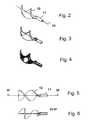
- Fig. 2first shows an embodiment of a one-piece airfoil, which is helically rotated about an axis of rotation 10. There is provided a shaft 11 which connects axially to the blade 12, but this does not penetrate. The blade 12 is so far self-supporting and transmits the torque without a hub is necessary.
- the airfoil 12may be integral with the shaft extension 11 and optionally with a further shaft extension on the axially opposite side be prepared of the airfoil 12, for example in an injection molding of plastic.
- Fig. 2shows schematically the outer shape of the airfoil 12, without going into the internal structure in more detail. This will be described in more detail in the context of the invention with reference to the following figures below.
- Fig. 3shows the blade Fig. 2 from the same perspective, but invisible lines are shown in dashed lines.
- Fig. 4shows a representation in which based on hatching the three-dimensional shape is shown plastic.
- Fig. 5shows a side view of the airfoil 12 and the shaft extension 11, wherein a section is indicated by VI, which in more detail in the Fig. 6 is shown.
- Fig. 7shows another embodiment of a rotor in which the airfoil 12 is surrounded by a tubular support means or shell, with which it is rigidly connected in this embodiment, so that the tubular sheath or support means 13 rotates with the airfoil 12.
- the shellis connected by means of a fork-shaped holder 14 with the shaft extension 11.
- the holdercan also be designed as a spatially twisted triangular plate, which can be connected directly to the end of the blade 12.
- the sheathis advantageously compressible and expandable and gives the blade 12 support.
- the sheath 13may consist of a plastic tube piece, which of a Mesh wire mesh can be surrounded for support.
- the wire meshmay also consist of a shape memory material, so that it can support the sleeve 13 shaping its form changes.
- thiscan be connected to the inner sides of the sleeve 13 and are clamped by their expansion movement.
- Fig. 8shows the view Fig. 7 , in which invisible lines are shown in dashed lines, and Fig. 9 shows a three-dimensional representation of the airfoil 12, wherein the shape is highlighted by hatching.
- Fig. 10shows as a further variant of a sleeve 13 surrounded blade 12 ', which has a built-in shape shaft extension 11', which is not connected to the sleeve 13 by itself.
- Fig. 11shows an embodiment of a sleeve 13 with two shaft extensions 11 on both sides, which are each connected via a fork-shaped holder 14 with the sleeve 13, but not with the airfoil.
- the bladecan have a substantially constant cross section without thickening; Cross-sectional changes are by no means excluded. Accordingly, the torque is transmitted via the flat body itself, so no hub is needed.
- Fig. 12shows in more detail the structure of a typical airfoil 12, which is spanned by webs 15, 16, 17.
- edge strips 18, 19are shown, which can typically consist of the same material as the webs 15, 16, 17.
- the individual websare designed wavy, the respective wave contour remains within the blade leaf surface.
- the webs in the surface of the airfoilare tensioned and thus expandable and compressible.
- this wave structuregives a stiffening perpendicular to the blade surface.
- the websmay for example consist of a shape memory material such as nitinol, which additionally facilitates the compression and expansion of the airfoil 12.
- the blade 12 in the example shownconsists of a substantially rectangular frame, whose end-side edge strips 20, 21, located in Fig. 13 are rotated by 180 degrees about the rotation axis 10 against each other to form a helical structure.
- a high symmetry of the airfoilis achieved with a correspondingly symmetrical force distribution.
- the starting bodymay also have other basic shapes than the rectangular one, wherein it is advantageous if the body covers the cross-section of a rotor housing as far as possible later in helical form and simulates with its outer contour as accurately as possible the inner contour of the housing.
- the shaft extensions 11in one piece or by a welded connection with the webs 15, 16, 17 and the edge strips 18, 19, 20, 21 are connected, so that the entire rotor can be made particularly simple and inexpensive and reliable connections exist for transmitting the torque.
- the scaffold formed by the webs 15, 16, 17 and the edge strips 18, 19, 20, 21is typically covered with a thin, highly flexible film which forms the actual conveying surface.
- the compressionis facilitated because the webs can deform over their entire length, on the other hand, the rotor is flexible, whereby the introduction in compressed form along a blood vessel can be facilitated.
- the websare connected in places in nodes and form a network that gives the airfoil additional rigidity.
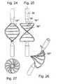
- FIGS. 16, 17 and 18show in two side views and in a three-dimensional view of a rotor with an airfoil 12 ', in which the individual webs 15', 16 'substantially along the axis of rotation 10 and thereby helically around it.
- Even with high fluid back pressure, resulting in high rotor speedscan adjust, evasive movements of the airfoil 12 'are closely limited by a good stabilization of the webs.
- the airfoil as a wholecan be regarded as a rectangular frame, whose two opposite end-side edge strips 20 ', 21' are rotated by 180 degrees about the axis of rotation 10 against each other.
- the production of a corresponding planar frame with parallel webs 15 ', 16'is particularly simple.
- FIGS. 20, 21, 22show in two side views and in three-dimensional view of an airfoil 12 "with two shaft extensions 11 ', wherein the blade horizontally transverse to the axis of rotation 10 extending webs 15", 16 ", which are straight in itself, the airfoil 12" as a whole, however, the same give helical structure, as they respect to the contour in the airfoil according to Fig. 17 given is.
- the webs 15", 16 “of the airfoil 12”can be stretched particularly efficiently during the expansion movement resulting in a stable airfoil.
- the stretched between the webs and the edge strips 20 ", 21” filmis also stabilized so that it is wrinkle-free in the fluid to be delivered.
- Fig. 23shows an end view of the rotor with the over the axis of rotation beyond webs.
- FIGS. 24-27show an embodiment similar to that in the FIGS. 20-23 shown, with an airfoil 12 "', the webs 15"', 16 “'transverse to the axis of rotation 10, wherein the individual webs 15 "', 16"' in itself not straight, but are wavy curved to achieve an optionally further improved blade geometry.
- FIGS. 12 to 26illustrated design principle any formation of the webs, so that there are extensive optimization options to design the pattern according to the requirements.
- This envisaged decompressed shapeis not necessarily the shape of the rotor in the operating state, as it may continue to deform under the influence of the fluid pressure.
- a particularly advantageous design of the rotoris now such that under the influence of the fluid pressure the rotor is subjected exclusively to elastic deformations and has the optimum geometry for the application in the intended operating point.
- the inventive design of the rotor of an axial pump with the corresponding bladeallows a material-saving and technically simple production of the rotor, which combines a good compressibility with high stability during operation.
Landscapes
- Health & Medical Sciences (AREA)
- Engineering & Computer Science (AREA)
- Heart & Thoracic Surgery (AREA)
- Mechanical Engineering (AREA)
- Life Sciences & Earth Sciences (AREA)
- Anesthesiology (AREA)
- Biomedical Technology (AREA)
- Hematology (AREA)
- Cardiology (AREA)
- Animal Behavior & Ethology (AREA)
- General Health & Medical Sciences (AREA)
- Public Health (AREA)
- Veterinary Medicine (AREA)
- General Engineering & Computer Science (AREA)
- Vascular Medicine (AREA)
- Structures Of Non-Positive Displacement Pumps (AREA)
- External Artificial Organs (AREA)
Abstract
Description
Translated fromGermanDie Erfindung liegt auf dem Gebiet des Maschinenbaus, insbesondere der Feinwerktechnik, und ist mit besonderem Gewinn auf dem medizinischen Gebiet anwendbar.The invention is in the field of mechanical engineering, in particular precision engineering, and is of particular benefit in the medical field.
Spezieller bezieht sich die Erfindung auf einen Rotor für eine Axialpumpe.More particularly, the invention relates to a rotor for an axial pump.
Insbesondere in der Medizintechnik werden für vielfältige Anwendungen Pumpen in kleinen Bauformen, sogenannte Mikropumpen, benötigt. Diese werden für mikroinvasive Anwendungen, beispielsweise zur Förderung körpereigener Flüssigkeiten in körpereigenen Hohlräumen bzw. Gefäßen eingesetzt. Üblicherweise werden solche Pumpen in Mikrobauform mit Kathetern verbunden und beispielsweise durch körpereigene Gefäße eingeführt und an den Anwendungsort gebracht. Ein spezielles Beispiel zum Einsatz derartiger Pumpen sind die sogenannten Herzpumpen, die durch ein großes Blutgefäß in den Körper eingeführt werden und die Blutförderung des Herzens unterstützen oder sogar ersetzen können.Especially in medical technology pumps in small designs, so-called micropumps are required for a variety of applications. These are used for micro-invasive applications, for example for the promotion of endogenous fluids in the body's own cavities or vessels. Usually, such pumps are connected in micro design with catheters and introduced, for example, by the body's own vessels and brought to the site. A specific example of the use of such pumps These are the so-called heart pumps, which are introduced into the body through a large blood vessel and can support or even replace the blood supply of the heart.
Speziell sind in diesem Zusammenhang Rotationspumpen bekannt geworden, die als Axialpumpen ausgeführt sind.Specifically, rotary pumps have become known in this context, which are designed as axial pumps.
Eine spezielle Eigenschaft mancher derartiger Pumpen ist außer ihrer an sich kleinen Bauform weiter die radiale Komprimierbarkeit, so dass eine derartige Pumpe zum Transport durch ein Blutgefäß komprimiert und nach dem Verbringen an den Einsatzort beispielsweise in einer Herzkammer expandiert werden kann.A special feature of some such pumps, in addition to their inherently small size, is the radial compressibility, so that such a pump can be compressed for transport through a blood vessel and expanded after it has been brought to the site, for example, in a heart chamber.
Eine derartige Pumpe ist beispielsweise aus den US-Offenlegungsschriften
Der vorliegenden Erfindung liegt vor dem Hintergrund des Standes der Technik die Aufgabe zugrunde, einen Rotor für eine Axialpumpe zu schaffen, der möglichst einfach aufgebaut und kostengünstig herstellbar ist. Er soll außerdem massearm sein und eine ausreichende Förderleistung ermöglichen.The present invention is based on the background of the prior art the object to provide a rotor for an axial pump, which is as simple as possible and inexpensive to produce. He should also be low in mass and allow sufficient flow.
Die Aufgabe wird mit dem Merkmalen der Erfindung gemäß Patentanspruch 1 gelöst.The object is achieved with the features of the invention according to claim 1.
Der erfindungsgemäße Rotor weist ein Schaufelblatt mit wenigstens einer Teilfläche auf, die sich quer zur Rotationsachse über diese hinweg erstreckt, wobei das Schaufelblatt Stege aufweist, die jeweils einzeln oder als Netzwerk verschiedene Randbereiche des Schaufelblattes miteinander verbinden.The rotor according to the invention has an airfoil with at least one partial surface which extends transversely to the axis of rotation beyond the latter, wherein the airfoil has webs which individually or as a network connect different edge regions of the airfoil to one another.
Das kann zum Beispiel bedeuten, dass wenigstens eine Teilfläche des Schaufelblattes derart gestaltet ist, dass Elemente der Teilfläche einander bezüglich der Rotationsachse auf derselben axialen Position auf verschiedenen Seiten der Rotationsachse gegenüberliegen. Dies kann beispielsweise derart realisiert sein, dass die Rotationsachse die Teilfläche durchsetzt und radial zu mehreren Seiten von Elementen der Teilfläche umgeben ist. Dieses Beispiel kann auch derart beschrieben werden, dass der Teilfläche ein Kreis einbeschrieben werden kann, den die Rotationsachse mittig durchsetzt.This may mean, for example, that at least a partial surface of the airfoil is designed such that elements of the subarea face each other with respect to the axis of rotation at the same axial position on different sides of the axis of rotation. This can for example be realized such that the axis of rotation passes through the partial surface and is surrounded radially to several sides of elements of the partial surface. This example can also be described such that the sub-area can be inscribed a circle through which the axis of rotation passes centrally.
Dabei weist das Schaufelblatt durchgehende Stege oder ein Netzwerk von Stegen auf, die verschiedene Randbereiche des Schaufelblattes, die auch als Randabschnitte bezeichnet werden können, miteinander verbinden und somit das Schaufelblatt aufspannen. Derartige Stege sind dazu geeignet, insbesondere gemeinsam mit gegebenenfalls vorgesehenen Randleisten des Schaufelblattes dieses aufzuspannen und die Befestigung einer Folie zu erlauben, die die Förderfläche des Schaufelblattes bildet und von den Stegen gestützt ist. Damit wird eine sehr leichte Bauart des Schaufelblattes realisiert, die dennoch die Schaffung einer großen Förderfläche erlaubt.In this case, the airfoil on through webs or a network of webs, which connect different edge regions of the airfoil, which can also be referred to as edge portions together, and thus span the airfoil. Such webs are suitable, in particular jointly with optionally provided edge strips of the airfoil to open this and to allow the attachment of a film which forms the conveying surface of the airfoil and is supported by the webs. Thus, a very lightweight design of the airfoil is realized, yet allows the creation of a large conveying surface.
Das Schaufelblatt ist vorteilhaft nabenlos gestaltet und selbsttragend realisiert.The blade is advantageously designed hubless and self-supporting realized.
Das bedeutet, dass das Drehmoment entlang des Rotors mittels der Schaufelblattfläche, also des flachen, gebogenen Körpers übertragen wird, der das Schaufelblatt im Wesentlichen bildet. Da die üblicherweise zur Übertragung des Drehmomentes und zur Halterung der Schaufelblattfläche vorgesehene Nabe ein wesentliches Volumen aufweist, das mit der Konstruktion gemäß der Erfindung eingespart werden kann, ist eine wesentlich stärkere Komprimierbarkeit des Rotors gemäß der Erfindung erreichbar.This means that the torque is transmitted along the rotor by means of the airfoil surface, ie the flat, curved body which essentially forms the airfoil. Since the hub usually provided for transmitting the torque and supporting the airfoil surface has a substantial volume that can be saved with the construction according to the invention, a much greater compressibility of the rotor according to the invention can be achieved.
Wenigstens einer der Stege kann zwei Randbereiche des Schaufelblattes verbinden, die einander radial bezüglich der Rotationsachse gegenüberliegen.At least one of the webs may connect two edge regions of the airfoil, which face each other radially with respect to the axis of rotation.
Es kann jedoch auch vorgesehen sein, dass wenigstens ein Steg zwei Randbereiche des Schaufelblattes verbindet, die in Längsrichtung der Rotationsachse gesehen einander gegenüberliegen.However, it can also be provided that at least one web connects two edge regions of the airfoil, which lie opposite one another in the longitudinal direction of the axis of rotation.
In jedem Fall kann die Gesamtfläche des Schaufelblattes nach einem gewünschten Muster durch Stege unterteilt sein, um eine gewünschte Schaufelblattfläche zu schaffen, die entweder durch die Stege selbst gebildet wird oder durch eine über die Stege gespannte Folie. Die Stege müssen ebenso wie die Förderfläche des Schaufelblattes nicht in einer Ebene verlaufen, sondern können eine dreidimensional, bespielsweise als Schraubenwendel verlaufende Fläche beschreiben. Dabei können die Stege auch punktweise an Knotenpunkten des Schaufelblattes miteinander verbunden sein, beispielsweise an solchen Punkten, die einer besonderen mechanischen Belastung ausgesetzt sind. Derartige Knotenpunkte können allerdings auch derart gewählt werden, dass durch sie ein Falten der Stege bei einer Kompressions- oder Expansionsbewegung des Schaufelblattes ermöglicht oder erleichtert wird.In any case, the total area of the airfoil may be subdivided by webs according to a desired pattern to provide a desired airfoil surface formed either by the webs themselves or by a film stretched over the webs. The webs, like the conveying surface of the airfoil, do not have to run in one plane, but can describe a three-dimensional, for example, helical surface. In this case, the webs may also be connected to one another at points at nodes of the airfoil, for example, at such points that are exposed to a special mechanical stress. However, such nodes may also be chosen such that they allow or facilitate folding of the webs during a compression or expansion movement of the airfoil.
Um die Stege entsprechend komprimierbar bzw. expandierbar zu gestalten, können sie vorteilhaft mäanderförmig gestaltet werden. Vorteilhaft ist die Mäanderstruktur in der Fläche des Schaufelblattes angelegt.In order to make the webs correspondingly compressible or expandable, they can advantageously be designed meandering. Advantageously, the meander structure is created in the surface of the airfoil.
Um einen entsprechenden Mechanismus zur Komprimierung und Expandierung des Schaufelblattes zu schaffen, kann vorteilhaft vorgesehen sein, dass die Stege aus einer Formgedächtnislegierung, beispielsweise Nitinol, bestehen. In diesem Fall kann durch Temperaturwechsel jeweils eine gewünschte Gestalt des Schaufelblattes angestrebt werden. Auch kann der Mechanismus des Komprimierens hier durch Ausnutzung de hyperelastischen Eigenschaften des Werkstoffes Nitinol unterstützt werden.In order to provide a corresponding mechanism for compressing and expanding the airfoil, it can be advantageously provided that the webs consist of a shape memory alloy, for example nitinol. In this case, a desired shape of the airfoil can be sought by changing the temperature. Also, the mechanism of compression here can be supported by exploiting the hyperelastic properties of Nitinol.
Wenn Randabschnitte des Schaufelblattes als Randleisten ausgebildet sind, so können diese das Schaufelblatt zusätzlich stabilisieren und gemeinsam mit den Stegen einen zuverlässigen Halt bzw. eine Stütze für eine entsprechende Schaufelblattfolie bilden. Eine derartige Folie kann dann an den Stegen und an den Randleisten oder Teilen der Randleisten beispielsweise durch Kleben befestigt sein.If edge portions of the airfoil are formed as edge strips, they can additionally stabilize the airfoil and together with the webs form a reliable hold or a support for a corresponding airfoil sheet. Such a film can then be attached to the webs and the edge strips or parts of the edge strips, for example by gluing.
Die Erfindung bezieht sich auch auf einen Rotor für eine Axialpumpe zur Förderung eines Fluids mit einer Rotationsachse und mit einem Schaufelblatt, welches nabenlos als ein bezüglich seiner Kontur flacher Körper gestaltet ist, der um eine Achse spiralförmig verdreht ist.
Diese Konstruktionsart lässt eine besonders einfache Herstellung zu und ist, insbesondere dadurch, dass keine Nabe benötigt wird, besonders einfach und auf ein besonders kleines Maß komprimierbar. Dies ist zum Einführen des Rotors beispielsweise über eine Blutbahn im Körper eines Menschen für medizinische Anwendungen entscheidend.The invention also relates to a rotor for an axial pump for conveying a fluid having an axis of rotation and having an airfoil, which has no hubs as a body which is flat relative to its contour is designed, which is twisted spirally about an axis.
This design allows for a particularly simple production and, in particular by the fact that no hub is needed, is particularly simple and compressible to a particularly small degree. This is crucial for introducing the rotor, for example via a bloodstream in the body of a human for medical applications.
Vorteilhaft ist das Schaufelblatt als ein Gitterwerk oder Netzwerk von Stegen aus einem ebenen Blech hergestellt.Advantageously, the blade is made as a gridwork or network of webs from a flat sheet.
Dies lässt eine Kostengünstige Serienherstellung mit gängigen Methoden der Blechbearbeitung zu.This allows a cost-effective serial production with common methods of sheet metal working.
Speziell kann vorteilhaft vorgesehen sein, dass das Schaufelblatt insbesondere aus einem Nitinolblech, durch Ausschneiden der Stege insbesondere durch Wasserschneiden, Laserschneiden oder Elektroerodieren hergestellt ist.Specifically, it may be advantageously provided that the blade is made in particular of a Nitinolblech by cutting out the webs in particular by water cutting, laser cutting or electroerodating.
Die Stege können dabei in der Blechebene und/oder senkrecht dazu mäanderförmig geformt sein.
Dadurch ergibt sich eine leichte Biegbarkeit bei der Kompression des Rotors in Radialrichtung.The webs may be formed meandering in the sheet plane and / or perpendicular thereto.
This results in a slight bendability in the compression of the rotor in the radial direction.
Weiterhin können die Stege in der Blechebene ein anderes Flächenträgheitsmoment aufweisen als senkrecht dazu.Furthermore, the webs in the sheet metal plane may have a different area moment of inertia than perpendicular thereto.
Dadurch kann gegenüber einer radialen Kompression des Schaufelblattes ein wesentlich geringerer widerstand realisiert werden als gegenüber Belastungen, die durch den Pumpbetrieb auf das Schaufelblatt wirken. Belastungen, die durch einen Fluiddruck gegen die Schaufelblattebene entstehen, werden somit sehr viel steifer aufgenommen.As a result, compared to a radial compression of the airfoil, a much lower resistance can be realized than to loads which act on the airfoil through the pumping operation. Loads caused by a fluid pressure against the blade blade plane are thus absorbed much stiffer.
Eine besonders einfache Ausgestaltung eines erfindungsgemäßen Schaufelblatts sieht vor, dass dieses als ein länglicher, insbesondere rechteckiger Körper gestaltet ist, der um eine Achse, insbesondere seine Längsmittelachse spiralförmig verdreht ist. Dabei kann die Spiralform auch unregelmäßig bezüglich der Steigung ausgestaltet oder gegebenenfalls anderweitig verzerrt sein.A particularly simple embodiment of a blade according to the invention provides that this is designed as an elongated, in particular rectangular body, which is spirally rotated about an axis, in particular its longitudinal central axis. In this case, the spiral shape can also be designed irregularly with respect to the slope or possibly otherwise distorted.
Die Verdrehungsachse des Körpers liegt beim Zusammenbau des Rotors vorzugsweise im Wesentlichen parallel zur Rotationsachse oder fällt mit dieser zusammen.The axis of rotation of the body is preferably substantially parallel to the axis of rotation during assembly of the rotor or coincides with this.
Damit ergibt sich eine symmetrische oder begrenzt unsymmetrische wendelförmige Gestaltung eines Schaufelblattes, beispielsweise dadurch, dass die Enden eines ebenen Rechtecks um 180 Grad oder um einen anderen Winkelbetrag um die Längsachse gegeneinander verdreht sind. Die Schaufelblattfläche ist dann als eine einzige, zusammenhängende Fläche ausgebildet, die sich über die Rotationsachse hinweg erstreckt und von dieser durchsetzt ist. Die Fläche kann dabei auch Ausnehmungen, beispielsweise im Bereich der Rotationsachse aufweisen.This results in a symmetrical or limited asymmetrical helical design of an airfoil, for example, by the fact that the ends of a flat rectangle are rotated by 180 degrees or by a different angular amount about the longitudinal axis against each other. The airfoil surface is then formed as a single contiguous surface extending across and penetrating the axis of rotation. The surface can also have recesses, for example in the region of the axis of rotation.
Ein derartiges Schaufelblatt kann bei entsprechend stabiler Gestaltung der Stege und Ränder selbsttragend ausgebildet sein, so dass beispielsweise das Drehmoment über das Schaufelblatt allein übertragen werden kann und keine Nabe benötigt wird. Die Steifheit des Schaufelblattes selbst reicht für die Förderung des Fluids aus, wenn dies von einem seiner Enden her angetrieben wird. Das Drehmoment wird dann über den stirnseitigen Rand des Schaufelblattes eingeleitet.Such an airfoil may be formed self-supporting in accordance with stable design of the webs and edges, so that for example the torque can be transmitted through the airfoil alone and no hub is needed. The stiffness of the airfoil itself is sufficient for the delivery of the fluid, if this from one of its ends is driven forth. The torque is then introduced via the front edge of the airfoil.
Es kann jedoch vorteilhaft auch vorgesehen sein, dass das Schaufelblatt mit einem dieses umgebenden hohlzylindrischen Bauteil fest verbunden ist. Ein derartiges hohlzylindrisches Bauteil kann beispielsweise als Ring oder Schlauchabschnitt vorgesehen sein, der das Schaufelblatt zusätzlich stabilisiert und mit diesem einstückig hergestellt sein kann. Es können jedoch auch mehrere koaxiale und axial zueinander beabstandete Ringe am Umfang des Rotors mit dem Schaufelblatt verbunden sein.However, it can also be advantageously provided that the blade is firmly connected to a hollow cylindrical member surrounding this. Such a hollow cylindrical component may be provided, for example, as a ring or hose section, which may additionally stabilize the blade and be made in one piece with this. However, a plurality of coaxial and axially spaced-apart rings may be connected to the blade at the periphery of the rotor.
Diese Ringe können dann axial zueinander durch Stege beabstandet und in sich radial komprimierbar ausgestaltet sein, um zum Zwecke der Einbringung in einen Körper zusammen mit dem Schaufelblatt kollabiert werden zu können.These rings can then be axially spaced from one another by webs and configured to be radially compressible in order to be collapsed together with the airfoil for the purpose of introduction into a body.
Die vorliegende Erfindung gestattet die einfachste Herstellung eines Schaufelblatts für eine Axialpumpe, bei der die Ränder und Verstärkungsstege des Schaufelblattes einstückig beispielsweise durch Spritzguss oder Bearbeitung eines Bleches hergestellt und mit einer Folie versehen sein können. Auch entsprechend sich axial an das Schaufelblatt anschließende Abschnitte können einstückig mit dem Schaufelblatt hergestellt sein, um axial an das Schaufelblatt anschließend eine drehbare Lagerung und die Einleitung eines Drehmoments zu ermöglichen.The present invention allows for the simplest manufacture of an airfoil for an axial pump in which the edges and reinforcing webs of the airfoil can be made in one piece and provided with a foil, for example by injection molding or machining a metal sheet. Corresponding sections axially adjoining the blade airfoil may also be produced in one piece with the airfoil, in order subsequently to allow a rotatable mounting and the introduction of a torque axially onto the airfoil.
Im Folgenden wird die Erfindung anhand eines Ausführungsbeispiels in einer Zeichnung gezeigt und anschließend erläutert. Dabei zeigt
- Fig. 1
- im Schnitt eine Übersicht über einen in eine Herzkammer eingeführten Herzkatheter mit einer Axialpumpe,
- Fig. 2
- ein Schaufelblatt einer Axialpumpe in drei- dimensionaler Ansicht,
- Fig. 3
- das Schaufelblatt aus
Fig. 2 , wobei un- sichtbare Konturen eingezeichnet sind, - Fig. 4
- das Schaufelblatt aus
Fig. 2 mit einer Her- vorhebung der sichtbaren Oberfläche durch Schraffur, - Fig. 5
- eine Seitenansicht des Schaufelblattes aus
Fig. 2 , - Fig. 6
- einen Schnitt der Ansicht aus
Fig. 5 , - Fig. 7
- eine Ausgestaltung eines Rotors einer Axialpumpe in dreidimensionaler Ansicht,
- Fig. 8
- die Ansicht aus
Fig. 7 mit eingezeichneten unsichtbaren Konturen sowie - Fig. 9
- eine teilweise durchbrochene Sicht der An- ordnung aus
Fig. 7 , - Fig. 10
- einen weiteren Rotor, bei dem die Befesti- gung einer Antriebswelle anders gelöst ist als bei der Ausführung gemäß
Fig. 7 , - Fig. 11
- einen Rotor mit zwei beiderseits befestig- ten Wellenansätzen,
- Fig. 12
- eine Seitenansicht eines Rotors mit mäan- derförmigen bzw. gewellten Stegen, die das Schaufelblatt aufspannen,
- Fig. 13
- das Schaufelblatt aus
Fig. 12 in einer um 90 Grad gedrehten Ansicht, - Fig. 14
- das Schaufelblatt aus
Fig. 12 in einer dreidimensionalen Ansicht, - Fig. 15
- das Schaufelblatt aus
Fig. 12 in einer axi- alen Draufsicht, - Fig. 16
- eine andere Variante eines Schaufelblattes mit im Wesentlichen in Richtung der Rota- tionsachse verlaufenden Stegen in einer Seitenansicht,
- Fig. 17
- die Anordnung aus
Fig. 16 in einer um 90 Grad gedrehten Seitenansicht, - Fig. 18
- die Anordnung aus
Fig. 16 in einer drei- dimensionalen Ansicht, - Fig. 19
- die Anordnung aus
Fig. 16 in einer axialen Draufsicht, - Fig. 20
- eine weitere Ausführungsform eines Rotors mit quer zur Rotationsachse gerade ver- laufenden Stegen in einer Seitenansicht,
- Fig. 21
- die Anordnung aus
Fig. 20 in einer um 90 Grad gedrehten Seitenansicht, - Fig. 22
- die Anordnung aus
Fig. 20 in einer drei- dimensionalen Ansicht, - Fig. 23
- die Anordnung aus
Fig. 20 in einer axialen Draufsicht, - Fig. 24
- eine weitere Ausführungsform eines Rotors mit quer zur Rotationsachse verlaufenden, gebogenen Stegen in einer Seitenansicht,
- Fig. 25
- die Ausführungsform gemäß
Fig. 24 in einer um 90 Grad gedrehten Seitenansicht, - Fig. 26
- die Ausführungsform gemäß
Fig. 24 in einer dreidimensionalen Ansicht und - Fig. 27
- eine Draufsicht auf die Anordnung gemäß
Fig. 24 in axialer Richtung.
- Fig. 1
- in section an overview of a cardiac catheter inserted into a heart chamber with an axial pump,
- Fig. 2
- an airfoil of an axial pump in a three-dimensional view,
- Fig. 3
- the blade out
Fig. 2 , where invisible contours are drawn, - Fig. 4
- the blade out
Fig. 2 with a highlighting of the visible surface by hatching, - Fig. 5
- a side view of the airfoil
Fig. 2 . - Fig. 6
- a section of the view
Fig. 5 . - Fig. 7
- an embodiment of a rotor of an axial pump in three-dimensional view,
- Fig. 8
- the view
Fig. 7 with drawn invisible contours as well - Fig. 9
- a partially open view of the arrangement
Fig. 7 . - Fig. 10
- another rotor, in which the fastening of a drive shaft is solved differently than in the embodiment according to
Fig. 7 . - Fig. 11
- a rotor with two shaft extensions fixed on both sides,
- Fig. 12
- FIG. 4 shows a side view of a rotor with meandering or corrugated webs which span the airfoil, FIG.
- Fig. 13
- the blade out
Fig. 12 in a 90 degree rotated view, - Fig. 14
- the blade out
Fig. 12 in a three-dimensional view, - Fig. 15
- the blade out
Fig. 12 in an axial plan view, - Fig. 16
- another variant of an airfoil with essentially extending in the direction of the axis of rotation tion webs in a side view,
- Fig. 17
- the arrangement
Fig. 16 in a 90 degree rotated side view, - Fig. 18
- the arrangement
Fig. 16 in a three-dimensional view, - Fig. 19
- the arrangement
Fig. 16 in an axial plan view, - Fig. 20
- 2 shows a further embodiment of a rotor with webs running straight across the axis of rotation, in a side view,
- Fig. 21
- the arrangement
Fig. 20 in a 90 degree rotated side view, - Fig. 22
- the arrangement
Fig. 20 in a three-dimensional view, - Fig. 23
- the arrangement
Fig. 20 in an axial plan view, - Fig. 24
- a further embodiment of a rotor with transversely to the axis of rotation extending, curved webs in a side view,
- Fig. 25
- the embodiment according to
Fig. 24 in a 90 degree rotated side view, - Fig. 26
- the embodiment according to
Fig. 24 in a three-dimensional view and - Fig. 27
- a plan view of the arrangement according to
Fig. 24 in the axial direction.
Durch den Hohlkatheter 3 verläuft eine antreibbare Welle 4, die durch einen außerhalb des Körpers angeordneten Motor 5 mit hoher Drehzahl angetrieben werden kann. Der Hohlkatheter 3 kann mit einer körperverträglichen Flüssigkeit gefüllt sein, die einerseits der Verminderung der Reibung der Welle und andererseits der Abführung von Wärme dienen kann.Through the
Am Ende des Hohlkatheters 3 ist eine Herzpumpe 6 angeordnet, die durch erste Öffnungen 7 innerhalb der Herzkammer 2 Blut ansaugt und dieses über zweite Öffnungen 8 innerhalb des Blutgefäßes 1 wieder abgibt. Auf diese Weise unterstützt die Pumpe 6 die Pumptätigkeit des Herzens oder ersetzt diese.At the end of the
Im Inneren der Pumpe 6 ist schematisch ein Rotor 9 dargestellt, der um seine Längsachse, angetrieben durch die Welle 4, rotiert und in axialer Richtung von der Herzkammer 2 zum Blutgefäß 1 hin das Blut fördert. Typischerweise ist eine derartige Axialpumpe mit einem Gehäuse und einem darin gelagerten Rotor mit Förderschaufeln versehen.Inside the
Derartige Herzpumpen sind bereits in verschiedenen Bauformen bekannt, wobei insbesondere die radiale Komprimierbarkeit solcher Pumpen für ihre Leistungsfähigkeit eine große Rolle spielt. Die Pumpen sollen in komprimierter Form durch das Blutgefäß 1 einbringbar und daraufhin expandierbar sein, damit die Förderschaufeln mit möglichst großen Förderflächen und in einem ausreichend großen Strömungsquerschnitt das Blut fördern können. Hierzu sind verschiedene Rotorkonstruktionen mit faltbaren Rotoren und Gehäusen bereits bekannt. Der erfindungsgemäße Rotor wird anhand der folgenden Figuren genauer geschildert.Such heart pumps are already known in various designs, in particular, the radial compressibility of such pumps for their performance plays a major role. The pumps should be introduced in compressed form through the blood vessel 1 and then expandable so that the delivery blades with the largest possible delivery surfaces and in a sufficiently large flow cross-section can promote the blood. For this purpose, various rotor designs with foldable rotors and housings are already known. The rotor according to the invention will be described in detail with reference to the following figures.
Das Schaufelblatt 12 kann einstückig mit dem Wellenansatz 11 und gegebenenfalls mit einem weiteren Wellenansatz auf der axial gegenüberliegenden Seite des Schaufelblattes 12 hergestellt sein, beispielsweise in einem Spritzgussverfahren aus Kunststoff.The
Die
Die Hülle ist mittels einer gabelförmigen Halterung 14 mit dem Wellenansatz 11 verbunden. Die Halterung kann auch als räumlich verdrehte dreieckige Platte ausgeführt sein, die mit dem Ende des Schaufelblattes 12 direkt verbunden sein kann. Die Hülle ist vorteilhaft komprimierbar und expandierbar und verleiht dem Schaufelblatt 12 Halt. Beispielsweise kann die Hülle 13 aus einem Kunststoffschlauchstück bestehen, das von einem
Maschendrahtgeflecht zur Stützung umgeben sein kann.
The shell is connected by means of a fork-shaped
Mesh wire mesh can be surrounded for support.
Das Maschendrahtgeflecht kann auch aus einem Formgedächtnismaterial bestehen, so dass dieses über seine Formveränderungen die Hülse 13 formgebend stützen kann. Insbesondere in dem Fall, dass das Schaufelblatt 12 nabenlos ausgebildet und nicht selbsttragend stabilisiert ist, kann dieses mit den Innenseiten der Hülse 13 verbunden sein und durch deren Expansionsbewegung aufgespannt werden.The wire mesh may also consist of a shape memory material, so that it can support the
Wie in den
Die Stege können beispielsweise aus einem Formgedächtnismaterial wie Nitinol bestehen, was die Komprimierung und Expandierung des Schaufelblattes 12 zusätzlich erleichtert.The webs may for example consist of a shape memory material such as nitinol, which additionally facilitates the compression and expansion of the
Grundsätzlich besteht das Schaufelblatt 12 in dem dargestellten Beispiel aus einem im Wesentlichen rechteckigen Rahmen, dessen endseitige Randleisten 20, 21, eingezeichnet in
Durch das Fehlen einer Nabe in dem axialen Bereich des Schaufelblattes 12 wird einerseits die Komprimierung erleichtert, da die Stege sich auf ihrer gesamten Länge verformen können, andererseits wird der Rotor biegsam, wodurch das Einführen in komprimierter Form längs eines Blutgefäßes erleichtert werden kann. Gemäß der beschriebenen Ausführungsform sind die Stege stellenweise in Knotenpunkten verbunden und bilden ein Netzwerk, das dem Schaufelblatt zusätzliche Steifigkeit verleiht.The lack of a hub in the axial region of the
Die
Die
Die
Steges aus der geraden Richtung bei Einnehmen der dargestellten Wendelform des Schaufelblattes 12"' erleichtert. Es kann aber auch durch eine definierte Vorbiegung der Stege erreicht werden. Der hierdurch erzielte Vorteil ist einerseits, dass die Stege beim Komprimieren eine definierte Vorzugsrichtung einnehmen, so dass es beim Komprimieren nicht zu undefinierten Knickbelastungen der Stege kommt. Ein weiterer Vorteil besteht darin, dass sich die vorgekrümmten Stege wenn sie im Betriebszustand dem Fluiddruck ausweichen, was bei derart elastischen Strukturen nahezu unvermeidbar ist, eine zunehmend gerade Form annehmen. Der Rotor der
Auch bei dieser Ausführungsform, wie bei den übrigen oben geschilderten, ist das Schaufelblatt insgesamt von Randleisten zum Befestigen der die Förderfläche bildenden Folie und zur Stabilisierung des Schaufelblattes umgeben.The
However, it can also be achieved by a defined pre-bending of the webs The advantage achieved on the one hand is that the webs adopt a defined preferred direction during compression, so that it Another advantage is that the pre-curved webs, when they dodge the fluid pressure in the operating state, which is almost unavoidable in such elastic structures, take on an increasingly straight shape
Also in this embodiment, as in the other above-described, the airfoil is surrounded in total by edge strips for securing the foil forming the conveying surface and for stabilizing the airfoil.
Grundsätzlich erlaubt das in den
In einer vorteilhaften Ausführungsform sind die dabei die Stege so ausgebildet, dass bei der Verformung des Rotors in die vorgesehene komprimierte Form ausschließlich elastische Verformungen auftreten, so dass sich der Rotor nach Wegfall der die Komprimierung auslösenden Kräfte selbsttätig in die vorgesehene dekomprimierte Form entfalten kann.In an advantageous embodiment, while the webs are formed so that in the deformation of the Rotor in the intended compressed form only elastic deformations occur, so that the rotor can automatically unfold after elimination of the compression triggering forces in the intended decompressed form.
Diese vorgesehene dekomprimierte Form ist nicht zwingend die Form des Rotors im Betriebszustand, da dieser sich unter dem Einfluss des Fluiddrucks möglicherweise weiter verformt.This envisaged decompressed shape is not necessarily the shape of the rotor in the operating state, as it may continue to deform under the influence of the fluid pressure.
Eine besonders vorteilhafte Gestaltung des Rotors ist nun derart, dass der Rotor unter dem Einfluss des Fluiddrucks ausschließlich elastischen Verformungen unterliegt und im vorgesehenen Arbeitspunkt die für den Anwendungsfall optimale Geometrie aufweist.A particularly advantageous design of the rotor is now such that under the influence of the fluid pressure the rotor is subjected exclusively to elastic deformations and has the optimum geometry for the application in the intended operating point.
Insgesamt erlaubt die erfindungsgemäße Gestaltung des Rotors einer Axialpumpe mit dem entsprechenden Schaufelblatt eine Material sparende und technisch einfache Herstellung des Rotors, die eine gute Komprimierbarkeit mit hoher Stabilität im Betrieb verbindet.Overall, the inventive design of the rotor of an axial pump with the corresponding blade allows a material-saving and technically simple production of the rotor, which combines a good compressibility with high stability during operation.
Claims (18)
Translated fromGermanPriority Applications (5)
| Application Number | Priority Date | Filing Date | Title |
|---|---|---|---|
| EP09075440AEP2298372A1 (en) | 2009-09-22 | 2009-09-22 | Rotor for an axial pump for transporting a fluid |
| US13/261,206US9028216B2 (en) | 2009-09-22 | 2010-09-22 | Rotor for an axial flow pump for conveying a fluid |
| DE112010003744.2TDE112010003744B4 (en) | 2009-09-22 | 2010-09-22 | Rotor for an axial pump for conveying a fluid |
| CN201080042108.7ACN102665784B (en) | 2009-09-22 | 2010-09-22 | Rotating element of an axial flow pump for conveying fluids |
| PCT/EP2010/005866WO2011035926A1 (en) | 2009-09-22 | 2010-09-22 | Rotor for an axial flow pump for conveying a fluid |
Applications Claiming Priority (1)
| Application Number | Priority Date | Filing Date | Title |
|---|---|---|---|
| EP09075440AEP2298372A1 (en) | 2009-09-22 | 2009-09-22 | Rotor for an axial pump for transporting a fluid |
Publications (1)
| Publication Number | Publication Date |
|---|---|
| EP2298372A1true EP2298372A1 (en) | 2011-03-23 |
Family
ID=41668500
Family Applications (1)
| Application Number | Title | Priority Date | Filing Date |
|---|---|---|---|
| EP09075440AWithdrawnEP2298372A1 (en) | 2009-09-22 | 2009-09-22 | Rotor for an axial pump for transporting a fluid |
Country Status (5)
| Country | Link |
|---|---|
| US (1) | US9028216B2 (en) |
| EP (1) | EP2298372A1 (en) |
| CN (1) | CN102665784B (en) |
| DE (1) | DE112010003744B4 (en) |
| WO (1) | WO2011035926A1 (en) |
Cited By (11)
| Publication number | Priority date | Publication date | Assignee | Title |
|---|---|---|---|---|
| US10722631B2 (en) | 2018-02-01 | 2020-07-28 | Shifamed Holdings, Llc | Intravascular blood pumps and methods of use and manufacture |
| US11185677B2 (en) | 2017-06-07 | 2021-11-30 | Shifamed Holdings, Llc | Intravascular fluid movement devices, systems, and methods of use |
| US11511103B2 (en) | 2017-11-13 | 2022-11-29 | Shifamed Holdings, Llc | Intravascular fluid movement devices, systems, and methods of use |
| US11654275B2 (en) | 2019-07-22 | 2023-05-23 | Shifamed Holdings, Llc | Intravascular blood pumps with struts and methods of use and manufacture |
| US11724089B2 (en) | 2019-09-25 | 2023-08-15 | Shifamed Holdings, Llc | Intravascular blood pump systems and methods of use and control thereof |
| US11964145B2 (en) | 2019-07-12 | 2024-04-23 | Shifamed Holdings, Llc | Intravascular blood pumps and methods of manufacture and use |
| US12102815B2 (en) | 2019-09-25 | 2024-10-01 | Shifamed Holdings, Llc | Catheter blood pumps and collapsible pump housings |
| US12121713B2 (en) | 2019-09-25 | 2024-10-22 | Shifamed Holdings, Llc | Catheter blood pumps and collapsible blood conduits |
| US12161857B2 (en) | 2018-07-31 | 2024-12-10 | Shifamed Holdings, Llc | Intravascular blood pumps and methods of use |
| US12220570B2 (en) | 2018-10-05 | 2025-02-11 | Shifamed Holdings, Llc | Intravascular blood pumps and methods of use |
| US12409310B2 (en) | 2019-12-11 | 2025-09-09 | Shifamed Holdings, Llc | Descending aorta and vena cava blood pumps |
Families Citing this family (87)
| Publication number | Priority date | Publication date | Assignee | Title |
|---|---|---|---|---|
| US7393181B2 (en) | 2004-09-17 | 2008-07-01 | The Penn State Research Foundation | Expandable impeller pump |
| CN102380135A (en) | 2006-03-23 | 2012-03-21 | 宾州研究基金会 | Heart assist device with expandable impeller pump |
| EP2194278A1 (en) | 2008-12-05 | 2010-06-09 | ECP Entwicklungsgesellschaft mbH | Fluid pump with a rotor |
| EP2216059A1 (en) | 2009-02-04 | 2010-08-11 | ECP Entwicklungsgesellschaft mbH | Catheter device with a catheter and an actuation device |
| EP2229965A1 (en) | 2009-03-18 | 2010-09-22 | ECP Entwicklungsgesellschaft mbH | Fluid pump with particular form of a rotor blade |
| EP2246078A1 (en) | 2009-04-29 | 2010-11-03 | ECP Entwicklungsgesellschaft mbH | Shaft assembly with a shaft which moves within a fluid-filled casing |
| EP2248544A1 (en) | 2009-05-05 | 2010-11-10 | ECP Entwicklungsgesellschaft mbH | Fluid pump with variable circumference, particularly for medical use |
| EP2266640A1 (en) | 2009-06-25 | 2010-12-29 | ECP Entwicklungsgesellschaft mbH | Compressible and expandable turbine blade for a fluid pump |
| EP2282070B1 (en) | 2009-08-06 | 2012-10-17 | ECP Entwicklungsgesellschaft mbH | Catheter device with a coupling device for a drive device |
| EP2298373A1 (en) | 2009-09-22 | 2011-03-23 | ECP Entwicklungsgesellschaft mbH | Fluid pump with at least one turbine blade and a seating device |
| EP2298371A1 (en) | 2009-09-22 | 2011-03-23 | ECP Entwicklungsgesellschaft mbH | Function element, in particular fluid pump with a housing and a transport element |
| EP2298372A1 (en) | 2009-09-22 | 2011-03-23 | ECP Entwicklungsgesellschaft mbH | Rotor for an axial pump for transporting a fluid |
| EP2299119B1 (en) | 2009-09-22 | 2018-11-07 | ECP Entwicklungsgesellschaft mbH | Inflatable rotor for a fluid pump |
| EP2314330A1 (en) | 2009-10-23 | 2011-04-27 | ECP Entwicklungsgesellschaft mbH | Flexible shaft arrangement |
| EP2314331B1 (en) | 2009-10-23 | 2013-12-11 | ECP Entwicklungsgesellschaft mbH | Catheter pump arrangement and flexible shaft arrangement with a cable core |
| EP2338540A1 (en) | 2009-12-23 | 2011-06-29 | ECP Entwicklungsgesellschaft mbH | Delivery blade for a compressible rotor |
| EP2338541A1 (en) | 2009-12-23 | 2011-06-29 | ECP Entwicklungsgesellschaft mbH | Radial compressible and expandable rotor for a fluid pump |
| EP2338539A1 (en) | 2009-12-23 | 2011-06-29 | ECP Entwicklungsgesellschaft mbH | Pump device with a detection device |
| EP2347778A1 (en) | 2010-01-25 | 2011-07-27 | ECP Entwicklungsgesellschaft mbH | Fluid pump with a radially compressible rotor |
| EP2363157A1 (en) | 2010-03-05 | 2011-09-07 | ECP Entwicklungsgesellschaft mbH | Device for exerting mechanical force on a medium, in particular fluid pump |
| EP2388029A1 (en) | 2010-05-17 | 2011-11-23 | ECP Entwicklungsgesellschaft mbH | Pump array |
| EP2399639A1 (en) | 2010-06-25 | 2011-12-28 | ECP Entwicklungsgesellschaft mbH | System for introducing a pump |
| EP2407185A1 (en) | 2010-07-15 | 2012-01-18 | ECP Entwicklungsgesellschaft mbH | Radial compressible and expandable rotor for a pump with a turbine blade |
| EP2407186A1 (en) | 2010-07-15 | 2012-01-18 | ECP Entwicklungsgesellschaft mbH | Rotor for a pump, produced with an initial elastic material |
| EP2407187A3 (en) | 2010-07-15 | 2012-06-20 | ECP Entwicklungsgesellschaft mbH | Blood pump for invasive application within the body of a patient |
| EP2422735A1 (en) | 2010-08-27 | 2012-02-29 | ECP Entwicklungsgesellschaft mbH | Implantable blood transportation device, manipulation device and coupling device |
| WO2012094641A2 (en) | 2011-01-06 | 2012-07-12 | Thoratec Corporation | Percutaneous heart pump |
| EP2497521A1 (en) | 2011-03-10 | 2012-09-12 | ECP Entwicklungsgesellschaft mbH | Push device for axial insertion of a string-shaped, flexible body |
| US8734331B2 (en) | 2011-08-29 | 2014-05-27 | Minnetronix, Inc. | Expandable blood pumps and methods of their deployment and use |
| US9162017B2 (en) | 2011-08-29 | 2015-10-20 | Minnetronix, Inc. | Expandable vascular pump |
| US8849398B2 (en) | 2011-08-29 | 2014-09-30 | Minnetronix, Inc. | Expandable blood pump for cardiac support |
| EP2564771A1 (en) | 2011-09-05 | 2013-03-06 | ECP Entwicklungsgesellschaft mbH | Medicinal product with a functional element for invasive use in the body of a patient |
| US8926492B2 (en) | 2011-10-11 | 2015-01-06 | Ecp Entwicklungsgesellschaft Mbh | Housing for a functional element |
| US9446179B2 (en) | 2012-05-14 | 2016-09-20 | Thoratec Corporation | Distal bearing support |
| US9327067B2 (en)* | 2012-05-14 | 2016-05-03 | Thoratec Corporation | Impeller for catheter pump |
| US8721517B2 (en) | 2012-05-14 | 2014-05-13 | Thoratec Corporation | Impeller for catheter pump |
| US9872947B2 (en) | 2012-05-14 | 2018-01-23 | Tc1 Llc | Sheath system for catheter pump |
| EP4218887A1 (en) | 2012-05-14 | 2023-08-02 | Tc1 Llc | Mechanical circulatory support device for stabilizing a patient after cardiogenic shock |
| CN108742951B (en) | 2012-06-06 | 2021-05-25 | 洋红医疗有限公司 | Artificial kidney valve |
| US9358329B2 (en) | 2012-07-03 | 2016-06-07 | Thoratec Corporation | Catheter pump |
| EP4186557A1 (en) | 2012-07-03 | 2023-05-31 | Tc1 Llc | Motor assembly for catheter pump |
| US9421311B2 (en) | 2012-07-03 | 2016-08-23 | Thoratec Corporation | Motor assembly for catheter pump |
| EP2745869A1 (en)* | 2012-12-21 | 2014-06-25 | ECP Entwicklungsgesellschaft mbH | Sluice assembly for the introduction of a cord-like body, in particular of a catheter, into a patient |
| US10583231B2 (en) | 2013-03-13 | 2020-03-10 | Magenta Medical Ltd. | Blood pump |
| EP4233702A3 (en)* | 2013-03-13 | 2023-12-20 | Magenta Medical Ltd. | Manufacture of an impeller |
| WO2014164136A1 (en) | 2013-03-13 | 2014-10-09 | Thoratec Corporation | Fluid handling system |
| US11077294B2 (en) | 2013-03-13 | 2021-08-03 | Tc1 Llc | Sheath assembly for catheter pump |
| US11033728B2 (en) | 2013-03-13 | 2021-06-15 | Tc1 Llc | Fluid handling system |
| US9308302B2 (en) | 2013-03-15 | 2016-04-12 | Thoratec Corporation | Catheter pump assembly including a stator |
| EP4190376A1 (en)* | 2013-03-15 | 2023-06-07 | Tc1 Llc | Catheter pump assembly including a stator |
| US9764113B2 (en) | 2013-12-11 | 2017-09-19 | Magenta Medical Ltd | Curved catheter |
| EP3131597B1 (en) | 2014-04-15 | 2020-12-02 | Tc1 Llc | Catheter pump introducer systems |
| WO2015160943A1 (en) | 2014-04-15 | 2015-10-22 | Thoratec Corporation | Sensors for catheter pumps |
| US10583232B2 (en) | 2014-04-15 | 2020-03-10 | Tc1 Llc | Catheter pump with off-set motor position |
| EP3131599B1 (en) | 2014-04-15 | 2019-02-20 | Tc1 Llc | Catheter pump with access ports |
| EP3583973A1 (en) | 2014-08-18 | 2019-12-25 | Tc1 Llc | Guide features for percutaneous catheter pump |
| US9770543B2 (en) | 2015-01-22 | 2017-09-26 | Tc1 Llc | Reduced rotational mass motor assembly for catheter pump |
| US9675738B2 (en) | 2015-01-22 | 2017-06-13 | Tc1 Llc | Attachment mechanisms for motor of catheter pump |
| WO2016118781A2 (en) | 2015-01-22 | 2016-07-28 | Thoratec Corporation | Motor assembly with heat exchanger for catheter pump |
| US10350341B2 (en) | 2015-03-20 | 2019-07-16 | Drexel University | Impellers, blood pumps, and methods of treating a subject |
| US9907890B2 (en) | 2015-04-16 | 2018-03-06 | Tc1 Llc | Catheter pump with positioning brace |
| WO2016185473A1 (en) | 2015-05-18 | 2016-11-24 | Magenta Medical Ltd. | Blood pump |
| US11160970B2 (en) | 2016-07-21 | 2021-11-02 | Tc1 Llc | Fluid seals for catheter pump motor assembly |
| EP3808401A1 (en) | 2016-07-21 | 2021-04-21 | Tc1 Llc | Gas-filled chamber for catheter pump motor assembly |
| EP3518825B1 (en) | 2016-09-29 | 2020-05-27 | Magenta Medical Ltd. | Blood vessel tube |
| CA3039285A1 (en) | 2016-10-25 | 2018-05-03 | Magenta Medical Ltd. | Ventricular assist device |
| JP7094279B2 (en) | 2016-11-23 | 2022-07-01 | マジェンタ・メディカル・リミテッド | Blood pump |
| US10905808B2 (en) | 2018-01-10 | 2021-02-02 | Magenta Medical Ltd. | Drive cable for use with a blood pump |
| EP3638336B1 (en) | 2018-01-10 | 2022-04-06 | Magenta Medical Ltd. | Ventricular assist device |
| DE102018201030B4 (en) | 2018-01-24 | 2025-10-16 | Kardion Gmbh | Magnetic dome element with magnetic bearing function |
| US10893927B2 (en) | 2018-03-29 | 2021-01-19 | Magenta Medical Ltd. | Inferior vena cava blood-flow implant |
| DE102018207575A1 (en) | 2018-05-16 | 2019-11-21 | Kardion Gmbh | Magnetic face turning coupling for the transmission of torques |
| DE102018207611A1 (en) | 2018-05-16 | 2019-11-21 | Kardion Gmbh | Rotor bearing system |
| DE102018208539A1 (en) | 2018-05-30 | 2019-12-05 | Kardion Gmbh | A motor housing module for sealing an engine compartment of a motor of a cardiac assist system and cardiac assistance system and method for mounting a cardiac assist system |
| DE102018208538A1 (en) | 2018-05-30 | 2019-12-05 | Kardion Gmbh | Intravascular blood pump and process for the production of electrical conductors |
| DE102018208550A1 (en) | 2018-05-30 | 2019-12-05 | Kardion Gmbh | A lead device for directing blood flow to a cardiac assist system, cardiac assist system, and method of making a lead device |
| DE102018208541A1 (en) | 2018-05-30 | 2019-12-05 | Kardion Gmbh | Axial pump for a cardiac assist system and method of making an axial pump for a cardiac assist system |
| DE102018210076A1 (en) | 2018-06-21 | 2019-12-24 | Kardion Gmbh | Method and device for detecting a state of wear of a cardiac support system, method and device for operating a cardiac support system and cardiac support system |
| DE102018210058A1 (en) | 2018-06-21 | 2019-12-24 | Kardion Gmbh | Stator blade device for guiding the flow of a fluid flowing out of an outlet opening of a heart support system, heart support system with stator blade device, method for operating a stator blade device and manufacturing method |
| DE102018211327A1 (en) | 2018-07-10 | 2020-01-16 | Kardion Gmbh | Impeller for an implantable vascular support system |
| DE102018212153A1 (en) | 2018-07-20 | 2020-01-23 | Kardion Gmbh | Inlet line for a pump unit of a cardiac support system, cardiac support system and method for producing an inlet line for a pump unit of a cardiac support system |
| CN112654389A (en) | 2018-08-07 | 2021-04-13 | 开迪恩有限公司 | Bearing device for a cardiac support system and method for flushing an intermediate space in a bearing device for a cardiac support system |
| AU2020211431B2 (en) | 2019-01-24 | 2024-10-24 | Magenta Medical Ltd | Ventricular assist device |
| EP3972661B1 (en) | 2019-05-23 | 2024-09-11 | Magenta Medical Ltd. | Blood pumps |
| DE102020102474A1 (en) | 2020-01-31 | 2021-08-05 | Kardion Gmbh | Pump for conveying a fluid and method for manufacturing a pump |
| EP3984589B1 (en) | 2020-04-07 | 2023-08-23 | Magenta Medical Ltd. | Magnetic phase sensing |
| CN119327028B (en)* | 2024-10-28 | 2025-08-01 | 同济大学 | Micro pump head |
Citations (7)
| Publication number | Priority date | Publication date | Assignee | Title |
|---|---|---|---|---|
| US5112292A (en)* | 1989-01-09 | 1992-05-12 | American Biomed, Inc. | Helifoil pump |
| US5181868A (en)* | 1990-02-06 | 1993-01-26 | Reinhard Gabriel | Jet propulsion device for watercraft, aircraft, and circulating pumps |
| WO1999044651A1 (en)* | 1998-03-07 | 1999-09-10 | Guenther Rolf W | Self-deploying axial-flow pump introduced intravascularly for temporary cardiac support |
| EP1738783A1 (en)* | 2005-07-01 | 2007-01-03 | Universitätsspital Basel | Axial flow pump with helical blade |
| US20080114339A1 (en) | 2006-03-23 | 2008-05-15 | The Penn State Research Foundation | Heart assist device with expandable impeller pump |
| US20090060743A1 (en) | 2004-09-17 | 2009-03-05 | The Penn State Research Foundation | Expandable impeller pump |
| EP2047873A1 (en)* | 2007-10-08 | 2009-04-15 | Ais Gmbh Aachen Innovative Solutions | Catheter device |
Family Cites Families (171)
| Publication number | Priority date | Publication date | Assignee | Title |
|---|---|---|---|---|
| US3510229A (en) | 1968-07-23 | 1970-05-05 | Maytag Co | One-way pump |
| US3568659A (en) | 1968-09-24 | 1971-03-09 | James N Karnegis | Disposable percutaneous intracardiac pump and method of pumping blood |
| CH538410A (en) | 1971-02-17 | 1973-06-30 | L Somers S Brice | Flexible device for the transport of granular, powdery or fluid products |
| DE2113986A1 (en) | 1971-03-23 | 1972-09-28 | Svu Textilni | Artificial heart machine - with ptfe or similar inert plastic coated parts,as intracorperal replacement |
| US4014317A (en) | 1972-02-18 | 1977-03-29 | The United States Of America As Represented By The Department Of Health, Education And Welfare | Multipurpose cardiocirculatory assist cannula and methods of use thereof |
| US3812812A (en) | 1973-06-25 | 1974-05-28 | M Hurwitz | Trolling propeller with self adjusting hydrodynamic spoilers |
| US4207028A (en) | 1979-06-12 | 1980-06-10 | Ridder Sven O | Extendable and retractable propeller for watercraft |
| US4559951A (en) | 1982-11-29 | 1985-12-24 | Cardiac Pacemakers, Inc. | Catheter assembly |
| US4563181A (en) | 1983-02-18 | 1986-01-07 | Mallinckrodt, Inc. | Fused flexible tip catheter |
| US4686982A (en) | 1985-06-19 | 1987-08-18 | John Nash | Spiral wire bearing for rotating wire drive catheter |
| US4679558A (en) | 1985-08-12 | 1987-07-14 | Intravascular Surgical Instruments, Inc. | Catheter based surgical methods and apparatus therefor |
| US4801243A (en) | 1985-12-28 | 1989-01-31 | Bird-Johnson Company | Adjustable diameter screw propeller |
| US4747821A (en) | 1986-10-22 | 1988-05-31 | Intravascular Surgical Instruments, Inc. | Catheter with high speed moving working head |
| US4753221A (en) | 1986-10-22 | 1988-06-28 | Intravascular Surgical Instruments, Inc. | Blood pumping catheter and method of use |
| US4749376A (en) | 1986-10-24 | 1988-06-07 | Intravascular Surgical Instruments, Inc. | Reciprocating working head catheter |
| US4817613A (en) | 1987-07-13 | 1989-04-04 | Devices For Vascular Intervention, Inc. | Guiding catheter |
| US5154705A (en) | 1987-09-30 | 1992-10-13 | Lake Region Manufacturing Co., Inc. | Hollow lumen cable apparatus |
| US5061256A (en) | 1987-12-07 | 1991-10-29 | Johnson & Johnson | Inflow cannula for intravascular blood pumps |
| US5183384A (en) | 1988-05-16 | 1993-02-02 | Trumbly Joe H | Foldable propeller assembly |
| US5011469A (en) | 1988-08-29 | 1991-04-30 | Shiley, Inc. | Peripheral cardiopulmonary bypass and coronary reperfusion system |
| US4919647A (en) | 1988-10-13 | 1990-04-24 | Kensey Nash Corporation | Aortically located blood pumping catheter and method of use |
| US4957504A (en) | 1988-12-02 | 1990-09-18 | Chardack William M | Implantable blood pump |
| US4969865A (en) | 1989-01-09 | 1990-11-13 | American Biomed, Inc. | Helifoil pump |
| US4944722A (en) | 1989-02-23 | 1990-07-31 | Nimbus Medical, Inc. | Percutaneous axial flow blood pump |
| US5052404A (en) | 1989-03-02 | 1991-10-01 | The Microspring Company, Inc. | Torque transmitter |
| US4995857A (en) | 1989-04-07 | 1991-02-26 | Arnold John R | Left ventricular assist device and method for temporary and permanent procedures |
| US5042984A (en) | 1989-08-17 | 1991-08-27 | Kensey Nash Corporation | Catheter with working head having selectable impacting surfaces and method of using the same |
| US5097849A (en) | 1989-08-17 | 1992-03-24 | Kensey Nash Corporation | Method of use of catheter with working head having selectable impacting surfaces |
| US5040944A (en) | 1989-09-11 | 1991-08-20 | Cook Einar P | Pump having impeller rotational about convoluted stationary member |
| GB2239675A (en) | 1989-12-05 | 1991-07-10 | Man Fai Shiu | Pump for pumping liquid |
| US5118264A (en) | 1990-01-11 | 1992-06-02 | The Cleveland Clinic Foundation | Purge flow control in rotary blood pumps |
| US5145333A (en) | 1990-03-01 | 1992-09-08 | The Cleveland Clinic Foundation | Fluid motor driven blood pump |
| JPH0636821B2 (en) | 1990-03-08 | 1994-05-18 | 健二 山崎 | Implantable auxiliary artificial heart |
| US5108411A (en) | 1990-03-28 | 1992-04-28 | Cardiovascular Imaging Systems, Inc. | Flexible catheter drive cable |
| US5092844A (en) | 1990-04-10 | 1992-03-03 | Mayo Foundation For Medical Education And Research | Intracatheter perfusion pump apparatus and method |
| US5163910A (en) | 1990-04-10 | 1992-11-17 | Mayo Foundation For Medical Education And Research | Intracatheter perfusion pump apparatus and method |
| US5113872A (en) | 1990-04-18 | 1992-05-19 | Cordis Corporation | Guidewire extension system with connectors |
| US5117838A (en) | 1990-04-18 | 1992-06-02 | Cordis Corporation | Rotating guidewire extension system |
| US5813405A (en) | 1990-04-18 | 1998-09-29 | Cordis Corporation | Snap-in connection assembly for extension guidewire system |
| US5191888A (en) | 1990-04-18 | 1993-03-09 | Cordis Corporation | Assembly of an extension guidewire and an alignment tool for same |
| ES2020787A6 (en) | 1990-07-20 | 1991-09-16 | Figuera Aymerich Diego | Intra-ventricular expansible assist pump |
| US5192286A (en) | 1991-07-26 | 1993-03-09 | Regents Of The University Of California | Method and device for retrieving materials from body lumens |
| US5188621A (en) | 1991-08-26 | 1993-02-23 | Target Therapeutics Inc. | Extendable guidewire assembly |
| IT1251758B (en) | 1991-11-05 | 1995-05-23 | Roberto Parravicini | VENTRICULAR PUMPING ASSISTANCE ELEMENT, WITH EXTERNAL DRIVE |
| US5201679A (en) | 1991-12-13 | 1993-04-13 | Attwood Corporation | Marine propeller with breakaway hub |
| US5271415A (en) | 1992-01-28 | 1993-12-21 | Baxter International Inc. | Guidewire extension system |
| US6302910B1 (en) | 1992-06-23 | 2001-10-16 | Sun Medical Technology Research Corporation | Auxiliary artificial heart of an embedded type |
| US5300112A (en) | 1992-07-14 | 1994-04-05 | Aai Corporation | Articulated heart pump |
| US5676651A (en) | 1992-08-06 | 1997-10-14 | Electric Boat Corporation | Surgically implantable pump arrangement and method for pumping body fluids |
| SE501215C2 (en) | 1992-09-02 | 1994-12-12 | Oeyvind Reitan | catheter Pump |
| US5376114A (en) | 1992-10-30 | 1994-12-27 | Jarvik; Robert | Cannula pumps for temporary cardiac support and methods of their application and use |
| US5365943A (en) | 1993-03-12 | 1994-11-22 | C. R. Bard, Inc. | Anatomically matched steerable PTCA guidewire |
| JPH06346917A (en) | 1993-06-03 | 1994-12-20 | Shicoh Eng Co Ltd | Pressure-proof water-proof sealing system using unidirectional dynamic pressure bearing |
| US5368438A (en) | 1993-06-28 | 1994-11-29 | Baxter International Inc. | Blood pump |
| US5720300A (en) | 1993-11-10 | 1998-02-24 | C. R. Bard, Inc. | High performance wires for use in medical devices and alloys therefor |
| DK145093D0 (en) | 1993-12-23 | 1993-12-23 | Gori 1902 As | PROPELLER |
| US5531789A (en) | 1993-12-24 | 1996-07-02 | Sun Medical Technology Research Corporation | Sealing system of an artificial internal organ |
| US5613935A (en) | 1994-12-16 | 1997-03-25 | Jarvik; Robert | High reliability cardiac assist system |
| DE19535781C2 (en) | 1995-09-26 | 1999-11-11 | Fraunhofer Ges Forschung | Device for active flow support of body fluids |
| EP0768091B1 (en) | 1995-10-16 | 2003-07-30 | Sun Medical Technology Research Corporation | Artificial heart |
| US5701911A (en) | 1996-04-05 | 1997-12-30 | Medtronic, Inc. | Guide wire extension docking system |
| US6254359B1 (en) | 1996-05-10 | 2001-07-03 | The United States Of America As Represented By The Administrator Of The National Aeronautics And Space Administration | Method for providing a jewel bearing for supporting a pump rotor shaft |
| IL118352A0 (en) | 1996-05-21 | 1996-09-12 | Sudai Amnon | Apparatus and methods for revascularization |
| US5820571A (en) | 1996-06-24 | 1998-10-13 | C. R. Bard, Inc. | Medical backloading wire |
| US6015272A (en) | 1996-06-26 | 2000-01-18 | University Of Pittsburgh | Magnetically suspended miniature fluid pump and method of designing the same |
| US5779721A (en) | 1996-07-26 | 1998-07-14 | Kensey Nash Corporation | System and method of use for revascularizing stenotic bypass grafts and other blood vessels |
| US5851174A (en) | 1996-09-17 | 1998-12-22 | Robert Jarvik | Cardiac support device |
| ES2227718T3 (en) | 1996-10-04 | 2005-04-01 | United States Surgical Corporation | CIRCULATORY SUPPORT SYSTEM. |
| US5882329A (en) | 1997-02-12 | 1999-03-16 | Prolifix Medical, Inc. | Apparatus and method for removing stenotic material from stents |
| CA2206644A1 (en) | 1997-05-30 | 1998-11-30 | L. Conrad Pelletier | Ventricular assist device comprising enclosed-impeller axial flow blood pump |
| US6129704A (en) | 1997-06-12 | 2000-10-10 | Schneider (Usa) Inc. | Perfusion balloon catheter having a magnetically driven impeller |
| US6183412B1 (en) | 1997-10-02 | 2001-02-06 | Micromed Technology, Inc. | Implantable pump system |
| US5980471A (en) | 1997-10-10 | 1999-11-09 | Advanced Cardiovascular System, Inc. | Guidewire with tubular connector |
| US6007478A (en) | 1997-11-13 | 1999-12-28 | Impella Cardiotechnik Aktiengesellschaft | Cannula having constant wall thickness with increasing distal flexibility and method of making |
| DE19821307C1 (en)* | 1998-05-13 | 1999-10-21 | Impella Cardiotech Gmbh | Intra-cardiac blood pump |
| GB9824436D0 (en) | 1998-11-06 | 1999-01-06 | Habib Nagy A | Methods of treatment |
| US6308632B1 (en) | 1998-11-23 | 2001-10-30 | James E. Shaffer | Deployable folded propeller assembly for aerial projectiles |
| CA2256131A1 (en) | 1998-12-16 | 2000-06-16 | Micro Therapeutics, Inc. | Miniaturized medical brush |
| US7780628B1 (en) | 1999-01-11 | 2010-08-24 | Angiodynamics, Inc. | Apparatus and methods for treating congestive heart disease |
| US6123659A (en) | 1999-01-26 | 2000-09-26 | Nimbus Inc. | Blood pump with profiled outflow region |
| DE20007581U1 (en) | 1999-04-20 | 2000-10-19 | Mediport Kardiotechnik GmbH, 12247 Berlin | Device for the axial conveyance of fluid media |
| JP2001017552A (en) | 1999-06-18 | 2001-01-23 | Medos Medizintechnik Gmbh | Method to inject fluid in blood vessel of human body, and corresponding cannula |
| US6458139B1 (en) | 1999-06-21 | 2002-10-01 | Endovascular Technologies, Inc. | Filter/emboli extractor for use in variable sized blood vessels |
| US6506025B1 (en) | 1999-06-23 | 2003-01-14 | California Institute Of Technology | Bladeless pump |
| US6247892B1 (en) | 1999-07-26 | 2001-06-19 | Impsa International Inc. | Continuous flow rotary pump |
| AU5317799A (en) | 1999-07-26 | 2001-02-13 | Impsa International, Inc. | Continuous flow rotary pump |
| US6398714B1 (en) | 1999-07-29 | 2002-06-04 | Intra-Vasc.Nl B.V. | Cardiac assist catheter pump and catheter and fitting for use therein |
| US7022100B1 (en) | 1999-09-03 | 2006-04-04 | A-Med Systems, Inc. | Guidable intravascular blood pump and related methods |
| US6454775B1 (en) | 1999-12-06 | 2002-09-24 | Bacchus Vascular Inc. | Systems and methods for clot disruption and retrieval |
| JP2001207988A (en) | 2000-01-26 | 2001-08-03 | Nipro Corp | Magnetic driving type axial flow pump |
| SG86458A1 (en)* | 2000-03-01 | 2002-02-19 | Medinol Ltd | Longitudinally flexible stent |
| US20010031981A1 (en) | 2000-03-31 | 2001-10-18 | Evans Michael A. | Method and device for locating guidewire and treating chronic total occlusions |
| US6592612B1 (en) | 2000-05-04 | 2003-07-15 | Cardeon Corporation | Method and apparatus for providing heat exchange within a catheter body |
| US6537030B1 (en) | 2000-10-18 | 2003-03-25 | Fasco Industries, Inc. | Single piece impeller having radial output |
| DE20119322U1 (en) | 2000-11-21 | 2002-02-21 | Schering Ag, 13353 Berlin | Tubular vascular grafts (stents) |
| DE10058669B4 (en) | 2000-11-25 | 2004-05-06 | Impella Cardiotechnik Ag | micromotor |
| DE10059714C1 (en) | 2000-12-01 | 2002-05-08 | Impella Cardiotech Ag | Intravasal pump has pump stage fitted with flexible expandible sleeve contricted during insertion through blood vessel |
| DE10108810A1 (en) | 2001-02-16 | 2002-08-29 | Berlin Heart Ag | Device for the axial conveyance of liquids |
| US6517315B2 (en) | 2001-05-29 | 2003-02-11 | Hewlett-Packard Company | Enhanced performance fan with the use of winglets |
| DE10155011B4 (en) | 2001-11-02 | 2005-11-24 | Impella Cardiosystems Ag | Intra-aortic pump |
| US6981942B2 (en) | 2001-11-19 | 2006-01-03 | University Of Medicine And Dentristy Of New Jersey | Temporary blood circulation assist device |
| ATE485850T1 (en) | 2002-01-08 | 2010-11-15 | Micromed Technology Inc | SYSTEM FOR DETECTING VENTRICULAR COLLAPSE |
| RU2229899C2 (en) | 2002-03-20 | 2004-06-10 | Федеральный научно-производственный центр закрытое акционерное общество "Научно-производственный концерн (объединение) "ЭНЕРГИЯ" | Device for supporting assist blood circulation |
| AU2003236497A1 (en) | 2002-06-11 | 2003-12-22 | Walid Aboul-Hosn | Expandable blood pump and related methods |
| US20030231959A1 (en) | 2002-06-12 | 2003-12-18 | William Hackett | Impeller assembly for centrifugal pumps |
| US7118356B2 (en) | 2002-10-02 | 2006-10-10 | Nanyang Technological University | Fluid pump with a tubular driver body capable of selective axial expansion and contraction |
| US6860713B2 (en) | 2002-11-27 | 2005-03-01 | Nidec Corporation | Fan with collapsible blades, redundant fan system, and related method |
| US20040215222A1 (en) | 2003-04-25 | 2004-10-28 | Michael Krivoruchko | Intravascular material removal device |
| US7655022B2 (en) | 2003-04-28 | 2010-02-02 | Cardiac Pacemakers, Inc. | Compliant guiding catheter sheath system |
| US7074018B2 (en) | 2003-07-10 | 2006-07-11 | Sheldon Chang | Direct drive linear flow blood pump |
| DE10336902C5 (en) | 2003-08-08 | 2019-04-25 | Abiomed Europe Gmbh | Intracardiac pumping device |
| AU2003261026A1 (en) | 2003-09-02 | 2005-03-16 | Intra-Vasc.Nl B.V. | Catheter pump, catheter and fittings therefore and methods of using a catheter pump. |
| WO2005030316A1 (en) | 2003-09-26 | 2005-04-07 | Medtronic, Inc. | Sutureless pump connector |
| EP1670524A4 (en) | 2003-10-09 | 2012-12-26 | Thoratec Corp | Impeller |
| EP1718361B1 (en) | 2004-02-11 | 2015-06-17 | Fort Wayne Metals Research Products Corporation | Drawn strand filled tubing wire |
| US7942804B2 (en) | 2004-05-20 | 2011-05-17 | Cor-Med Vascular, Inc. | Replaceable expandable transmyocardial ventricular assist device |
| EP2151257B1 (en) | 2004-08-13 | 2013-04-17 | Delgado, Reynolds M., III | Apparatus for long-term assisting a left ventricle to pump blood |
| US7479102B2 (en) | 2005-02-28 | 2009-01-20 | Robert Jarvik | Minimally invasive transvalvular ventricular assist device |
| AU2006255059A1 (en) | 2005-06-06 | 2006-12-14 | Foster-Miller, Inc. | Blood pump |
| US7438699B2 (en) | 2006-03-06 | 2008-10-21 | Orqis Medical Corporation | Quick priming connectors for blood circuit |
| US20070213690A1 (en) | 2006-03-08 | 2007-09-13 | Nickolas Phillips | Blood conduit connector |
| DE102006036948A1 (en) | 2006-08-06 | 2008-02-07 | Akdis, Mustafa, Dipl.-Ing. | blood pump |
| CN101121045A (en)* | 2006-08-07 | 2008-02-13 | 李国荣 | Sleeved type permanent magnetic impeller axial flow type blood pump for assisting heart and assisting method |
| EP2061531B1 (en) | 2006-09-14 | 2016-04-13 | CircuLite, Inc. | Intravascular blood pump and catheter |
| US7988674B2 (en) | 2006-10-30 | 2011-08-02 | Medtronic, Inc. | Externally releasable body portal anchors and systems |
| US9028392B2 (en) | 2006-12-01 | 2015-05-12 | NuCardia, Inc. | Medical device |
| AU2008219653B2 (en) | 2007-02-26 | 2014-01-16 | Heartware, Inc. | Intravascular ventricular assist device |
| ES2605170T3 (en) | 2007-03-19 | 2017-03-13 | Boston Scientific Neuromodulation Corporation | Cable manufacturing procedures and apparatus with conductors and related flexible cable configurations |
| DE102007014224A1 (en) | 2007-03-24 | 2008-09-25 | Abiomed Europe Gmbh | Blood pump with micromotor |
| US9974894B2 (en) | 2007-04-05 | 2018-05-22 | Reliantheart, Inc. | Blood pump system |
| US20080275427A1 (en) | 2007-05-01 | 2008-11-06 | Sage Shahn S | Threaded catheter connector, system, and method |
| US8512312B2 (en) | 2007-05-01 | 2013-08-20 | Medtronic, Inc. | Offset catheter connector, system and method |
| US7828710B2 (en) | 2007-06-05 | 2010-11-09 | Medical Value Partners, Llc | Apparatus comprising a drive cable for a medical device |
| WO2009015784A1 (en) | 2007-07-30 | 2009-02-05 | Ifw Manfred Otte Gmbh | Mould-integrated plastifying unit |
| US8439859B2 (en) | 2007-10-08 | 2013-05-14 | Ais Gmbh Aachen Innovative Solutions | Catheter device |
| US8489190B2 (en) | 2007-10-08 | 2013-07-16 | Ais Gmbh Aachen Innovative Solutions | Catheter device |
| ATE480274T1 (en) | 2007-10-08 | 2010-09-15 | Ais Gmbh Aachen Innovative Sol | CATHETER DEVICE |
| CN201230980Y (en)* | 2008-03-21 | 2009-05-06 | 北京工业大学 | Magnetic force and fluid dynamic-pressure mixed suspended artificial heart blood pump |
| EP2194278A1 (en) | 2008-12-05 | 2010-06-09 | ECP Entwicklungsgesellschaft mbH | Fluid pump with a rotor |
| EP2216059A1 (en) | 2009-02-04 | 2010-08-11 | ECP Entwicklungsgesellschaft mbH | Catheter device with a catheter and an actuation device |
| EP2218469B1 (en) | 2009-02-12 | 2012-10-31 | ECP Entwicklungsgesellschaft mbH | Casing for a functional element |
| EP2229965A1 (en) | 2009-03-18 | 2010-09-22 | ECP Entwicklungsgesellschaft mbH | Fluid pump with particular form of a rotor blade |
| DE102010011998A1 (en) | 2009-03-24 | 2010-09-30 | Ecp Entwicklungsgesellschaft Mbh | Fluid pumping unit, particularly for medical area for use within body vessel, has fluid pump which consists of pump rotor and drive device for driving fluid pump, where drive device has fluid supply line and drive rotor driven by fluid |
| EP2246078A1 (en) | 2009-04-29 | 2010-11-03 | ECP Entwicklungsgesellschaft mbH | Shaft assembly with a shaft which moves within a fluid-filled casing |
| EP2248544A1 (en) | 2009-05-05 | 2010-11-10 | ECP Entwicklungsgesellschaft mbH | Fluid pump with variable circumference, particularly for medical use |
| US8617239B2 (en) | 2009-05-18 | 2013-12-31 | Cardiobridge Gmbh | Catheter pump |
| EP2266640A1 (en) | 2009-06-25 | 2010-12-29 | ECP Entwicklungsgesellschaft mbH | Compressible and expandable turbine blade for a fluid pump |
| EP2282070B1 (en) | 2009-08-06 | 2012-10-17 | ECP Entwicklungsgesellschaft mbH | Catheter device with a coupling device for a drive device |
| EP2299119B1 (en) | 2009-09-22 | 2018-11-07 | ECP Entwicklungsgesellschaft mbH | Inflatable rotor for a fluid pump |
| EP2298372A1 (en) | 2009-09-22 | 2011-03-23 | ECP Entwicklungsgesellschaft mbH | Rotor for an axial pump for transporting a fluid |
| EP2298371A1 (en) | 2009-09-22 | 2011-03-23 | ECP Entwicklungsgesellschaft mbH | Function element, in particular fluid pump with a housing and a transport element |
| EP2298373A1 (en) | 2009-09-22 | 2011-03-23 | ECP Entwicklungsgesellschaft mbH | Fluid pump with at least one turbine blade and a seating device |
| EP2314330A1 (en) | 2009-10-23 | 2011-04-27 | ECP Entwicklungsgesellschaft mbH | Flexible shaft arrangement |
| EP2314331B1 (en) | 2009-10-23 | 2013-12-11 | ECP Entwicklungsgesellschaft mbH | Catheter pump arrangement and flexible shaft arrangement with a cable core |
| EP2338541A1 (en) | 2009-12-23 | 2011-06-29 | ECP Entwicklungsgesellschaft mbH | Radial compressible and expandable rotor for a fluid pump |
| EP2338540A1 (en) | 2009-12-23 | 2011-06-29 | ECP Entwicklungsgesellschaft mbH | Delivery blade for a compressible rotor |
| EP2338539A1 (en) | 2009-12-23 | 2011-06-29 | ECP Entwicklungsgesellschaft mbH | Pump device with a detection device |
| EP2343091B1 (en) | 2010-01-08 | 2014-05-14 | ECP Entwicklungsgesellschaft mbH | Fluid pump with a transport device with controllable volume alteration |
| EP2347778A1 (en) | 2010-01-25 | 2011-07-27 | ECP Entwicklungsgesellschaft mbH | Fluid pump with a radially compressible rotor |
| EP2353626A1 (en) | 2010-01-27 | 2011-08-10 | ECP Entwicklungsgesellschaft mbH | Supply device for a fluid |
| EP2363157A1 (en) | 2010-03-05 | 2011-09-07 | ECP Entwicklungsgesellschaft mbH | Device for exerting mechanical force on a medium, in particular fluid pump |
| EP2388029A1 (en) | 2010-05-17 | 2011-11-23 | ECP Entwicklungsgesellschaft mbH | Pump array |
| EP2399639A1 (en) | 2010-06-25 | 2011-12-28 | ECP Entwicklungsgesellschaft mbH | System for introducing a pump |
| EP2407187A3 (en) | 2010-07-15 | 2012-06-20 | ECP Entwicklungsgesellschaft mbH | Blood pump for invasive application within the body of a patient |
| EP2407186A1 (en) | 2010-07-15 | 2012-01-18 | ECP Entwicklungsgesellschaft mbH | Rotor for a pump, produced with an initial elastic material |
| EP2407185A1 (en) | 2010-07-15 | 2012-01-18 | ECP Entwicklungsgesellschaft mbH | Radial compressible and expandable rotor for a pump with a turbine blade |
| EP2497521A1 (en) | 2011-03-10 | 2012-09-12 | ECP Entwicklungsgesellschaft mbH | Push device for axial insertion of a string-shaped, flexible body |
| EP2564771A1 (en) | 2011-09-05 | 2013-03-06 | ECP Entwicklungsgesellschaft mbH | Medicinal product with a functional element for invasive use in the body of a patient |
| EP2606919A1 (en) | 2011-12-22 | 2013-06-26 | ECP Entwicklungsgesellschaft mbH | Sluice device for inserting a catheter |
| EP2607712B1 (en) | 2011-12-22 | 2016-07-13 | ECP Entwicklungsgesellschaft mbH | Pump housing with an interior for holding a pump rotor |
| EP2606920A1 (en) | 2011-12-22 | 2013-06-26 | ECP Entwicklungsgesellschaft mbH | Sluice device for inserting a catheter |
- 2009
- 2009-09-22EPEP09075440Apatent/EP2298372A1/ennot_activeWithdrawn
- 2010
- 2010-09-22WOPCT/EP2010/005866patent/WO2011035926A1/enactiveIP Right Grant
- 2010-09-22CNCN201080042108.7Apatent/CN102665784B/enactiveActive
- 2010-09-22DEDE112010003744.2Tpatent/DE112010003744B4/enactiveActive
- 2010-09-22USUS13/261,206patent/US9028216B2/enactiveActive
Patent Citations (7)
| Publication number | Priority date | Publication date | Assignee | Title |
|---|---|---|---|---|
| US5112292A (en)* | 1989-01-09 | 1992-05-12 | American Biomed, Inc. | Helifoil pump |
| US5181868A (en)* | 1990-02-06 | 1993-01-26 | Reinhard Gabriel | Jet propulsion device for watercraft, aircraft, and circulating pumps |
| WO1999044651A1 (en)* | 1998-03-07 | 1999-09-10 | Guenther Rolf W | Self-deploying axial-flow pump introduced intravascularly for temporary cardiac support |
| US20090060743A1 (en) | 2004-09-17 | 2009-03-05 | The Penn State Research Foundation | Expandable impeller pump |
| EP1738783A1 (en)* | 2005-07-01 | 2007-01-03 | Universitätsspital Basel | Axial flow pump with helical blade |
| US20080114339A1 (en) | 2006-03-23 | 2008-05-15 | The Penn State Research Foundation | Heart assist device with expandable impeller pump |
| EP2047873A1 (en)* | 2007-10-08 | 2009-04-15 | Ais Gmbh Aachen Innovative Solutions | Catheter device |
Cited By (14)
| Publication number | Priority date | Publication date | Assignee | Title |
|---|---|---|---|---|
| US11185677B2 (en) | 2017-06-07 | 2021-11-30 | Shifamed Holdings, Llc | Intravascular fluid movement devices, systems, and methods of use |
| US11717670B2 (en) | 2017-06-07 | 2023-08-08 | Shifamed Holdings, LLP | Intravascular fluid movement devices, systems, and methods of use |
| US11511103B2 (en) | 2017-11-13 | 2022-11-29 | Shifamed Holdings, Llc | Intravascular fluid movement devices, systems, and methods of use |
| US11229784B2 (en) | 2018-02-01 | 2022-01-25 | Shifamed Holdings, Llc | Intravascular blood pumps and methods of use and manufacture |
| US10722631B2 (en) | 2018-02-01 | 2020-07-28 | Shifamed Holdings, Llc | Intravascular blood pumps and methods of use and manufacture |
| US12076545B2 (en) | 2018-02-01 | 2024-09-03 | Shifamed Holdings, Llc | Intravascular blood pumps and methods of use and manufacture |
| US12161857B2 (en) | 2018-07-31 | 2024-12-10 | Shifamed Holdings, Llc | Intravascular blood pumps and methods of use |
| US12220570B2 (en) | 2018-10-05 | 2025-02-11 | Shifamed Holdings, Llc | Intravascular blood pumps and methods of use |
| US11964145B2 (en) | 2019-07-12 | 2024-04-23 | Shifamed Holdings, Llc | Intravascular blood pumps and methods of manufacture and use |
| US11654275B2 (en) | 2019-07-22 | 2023-05-23 | Shifamed Holdings, Llc | Intravascular blood pumps with struts and methods of use and manufacture |
| US11724089B2 (en) | 2019-09-25 | 2023-08-15 | Shifamed Holdings, Llc | Intravascular blood pump systems and methods of use and control thereof |
| US12121713B2 (en) | 2019-09-25 | 2024-10-22 | Shifamed Holdings, Llc | Catheter blood pumps and collapsible blood conduits |
| US12102815B2 (en) | 2019-09-25 | 2024-10-01 | Shifamed Holdings, Llc | Catheter blood pumps and collapsible pump housings |
| US12409310B2 (en) | 2019-12-11 | 2025-09-09 | Shifamed Holdings, Llc | Descending aorta and vena cava blood pumps |
Also Published As
| Publication number | Publication date |
|---|---|
| DE112010003744B4 (en) | 2025-09-04 |
| DE112010003744T5 (en) | 2013-02-07 |
| US20120237357A1 (en) | 2012-09-20 |
| US9028216B2 (en) | 2015-05-12 |
| CN102665784A (en) | 2012-09-12 |
| CN102665784B (en) | 2015-08-26 |
| WO2011035926A1 (en) | 2011-03-31 |
Similar Documents
| Publication | Publication Date | Title |
|---|---|---|
| DE112010003744B4 (en) | Rotor for an axial pump for conveying a fluid | |
| DE112010004977B4 (en) | Radially compressible and expandable rotor for a fluid pump | |
| DE112010002711B4 (en) | Compressible and expandable blade for a fluid pump | |
| EP2407185A1 (en) | Radial compressible and expandable rotor for a pump with a turbine blade | |
| EP2229965A1 (en) | Fluid pump with particular form of a rotor blade | |
| EP3441616B1 (en) | Compressible rotor for a fluid pump | |
| EP3393543B1 (en) | Catheter pump with pump head for introduction in arterial vessel system | |
| DE112010003745T5 (en) | Fluid pump with at least one airfoil and a support means | |
| EP2999496B1 (en) | Pump, in particular a blood pump | |
| EP2338540A1 (en) | Delivery blade for a compressible rotor | |
| DE112011100345T5 (en) | Conveying device for a fluid | |
| EP3088018A1 (en) | Rotor for a fluid pump and method and mould for its preparation | |
| EP3266475A1 (en) | Blood pump used for cardiac support | |
| EP2761137B1 (en) | Blade of a row of rotor blades or stator blades for use in a turbomachine | |
| EP2194278A1 (en) | Fluid pump with a rotor | |
| DE2744366A1 (en) | IMPELLER FOR A RADIAL TURBO COMPRESSOR | |
| DE102015219530A1 (en) | Blade for a turbomachine, turbofan engine and a method for producing a blade | |
| EP2921714A1 (en) | Stator blade group | |
| DE102016121237B4 (en) | Hydraulic gerotor pump and manufacturing process of a gerotor pump | |
| EP0949419B1 (en) | Internal gear pump | |
| EP1766237B1 (en) | Single-winged vacuum pump | |
| WO2019086065A1 (en) | Additively manufactured intermediate channel for arranging between a low-pressure compressor and a high-pressure compressor, and corresponding manufacturing method | |
| WO2003021105A1 (en) | Flow engine | |
| EP1507958A1 (en) | Axial securing means for impeller blades | |
| EP2746537B1 (en) | Shrouded rotor blade with cutting tooth |
Legal Events
| Date | Code | Title | Description |
|---|---|---|---|
| PUAI | Public reference made under article 153(3) epc to a published international application that has entered the european phase | Free format text:ORIGINAL CODE: 0009012 | |
| AK | Designated contracting states | Kind code of ref document:A1 Designated state(s):AT BE BG CH CY CZ DE DK EE ES FI FR GB GR HR HU IE IS IT LI LT LU LV MC MK MT NL NO PL PT RO SE SI SK SM TR | |
| AX | Request for extension of the european patent | Extension state:AL BA RS | |
| STAA | Information on the status of an ep patent application or granted ep patent | Free format text:STATUS: THE APPLICATION IS DEEMED TO BE WITHDRAWN | |
| 18D | Application deemed to be withdrawn | Effective date:20110924 |