EP2298193A2 - Low energy or minimum disturbance method for measuring frequency response functions of ultrasonic surgical devices in determining optimum operating point - Google Patents
Low energy or minimum disturbance method for measuring frequency response functions of ultrasonic surgical devices in determining optimum operating pointDownload PDFInfo
- Publication number
- EP2298193A2 EP2298193A2EP10177202AEP10177202AEP2298193A2EP 2298193 A2EP2298193 A2EP 2298193A2EP 10177202 AEP10177202 AEP 10177202AEP 10177202 AEP10177202 AEP 10177202AEP 2298193 A2EP2298193 A2EP 2298193A2
- Authority
- EP
- European Patent Office
- Prior art keywords
- ultrasonic
- noise signal
- generator
- signal
- noise
- Prior art date
- Legal status (The legal status is an assumption and is not a legal conclusion. Google has not performed a legal analysis and makes no representation as to the accuracy of the status listed.)
- Granted
Links
- 238000000034methodMethods0.000titledescription11
- 238000005316response functionMethods0.000title1
- 238000012546transferMethods0.000claimsabstractdescription22
- 238000004804windingMethods0.000claimsdescription11
- 210000001519tissueAnatomy0.000description29
- 230000006870functionEffects0.000description16
- XLYOFNOQVPJJNP-UHFFFAOYSA-NwaterSubstancesOXLYOFNOQVPJJNP-UHFFFAOYSA-N0.000description10
- 239000002245particleSubstances0.000description8
- 238000001356surgical procedureMethods0.000description8
- 210000000988bone and boneAnatomy0.000description7
- 238000013467fragmentationMethods0.000description7
- 238000006062fragmentation reactionMethods0.000description7
- 230000007246mechanismEffects0.000description7
- 239000012634fragmentSubstances0.000description5
- 230000008859changeEffects0.000description4
- RTAQQCXQSZGOHL-UHFFFAOYSA-NTitaniumChemical compound[Ti]RTAQQCXQSZGOHL-UHFFFAOYSA-N0.000description3
- 229940030225antihemorrhagicsDrugs0.000description3
- 230000015271coagulationEffects0.000description3
- 238000005345coagulationMethods0.000description3
- 230000008878couplingEffects0.000description3
- 238000010168coupling processMethods0.000description3
- 238000005859coupling reactionMethods0.000description3
- 230000000025haemostatic effectEffects0.000description3
- 230000023597hemostasisEffects0.000description3
- 239000007788liquidSubstances0.000description3
- 239000000463materialSubstances0.000description3
- 230000009467reductionEffects0.000description3
- 239000000523sampleSubstances0.000description3
- 239000010936titaniumSubstances0.000description3
- 229910052719titaniumInorganic materials0.000description3
- 230000008901benefitEffects0.000description2
- 239000003795chemical substances by applicationSubstances0.000description2
- 230000001112coagulating effectEffects0.000description2
- 239000002826coolantSubstances0.000description2
- 239000000498cooling waterSubstances0.000description2
- 230000007423decreaseEffects0.000description2
- 230000000694effectsEffects0.000description2
- 230000002262irrigationEffects0.000description2
- 238000003973irrigationMethods0.000description2
- 230000007935neutral effectEffects0.000description2
- 230000001681protective effectEffects0.000description2
- 239000002023woodSubstances0.000description2
- 208000002177CataractDiseases0.000description1
- 206010028980NeoplasmDiseases0.000description1
- 238000005299abrasionMethods0.000description1
- 230000009471actionEffects0.000description1
- 239000003708ampulSubstances0.000description1
- 239000008280bloodSubstances0.000description1
- 210000004369bloodAnatomy0.000description1
- 210000004204blood vesselAnatomy0.000description1
- 210000001124body fluidAnatomy0.000description1
- 239000010839body fluidSubstances0.000description1
- 239000003990capacitorSubstances0.000description1
- 238000006243chemical reactionMethods0.000description1
- 238000004891communicationMethods0.000description1
- 239000000470constituentSubstances0.000description1
- 238000010276constructionMethods0.000description1
- 238000001816coolingMethods0.000description1
- 239000007799corkSubstances0.000description1
- 230000003247decreasing effectEffects0.000description1
- 230000007547defectEffects0.000description1
- 230000001419dependent effectEffects0.000description1
- 238000013461designMethods0.000description1
- 238000011161developmentMethods0.000description1
- 238000006073displacement reactionMethods0.000description1
- 210000004177elastic tissueAnatomy0.000description1
- 238000005516engineering processMethods0.000description1
- 238000001914filtrationMethods0.000description1
- 239000012530fluidSubstances0.000description1
- 230000035876healingEffects0.000description1
- 238000010438heat treatmentMethods0.000description1
- 230000006872improvementEffects0.000description1
- 208000014674injuryDiseases0.000description1
- 230000003993interactionEffects0.000description1
- 239000010985leatherSubstances0.000description1
- 239000004973liquid crystal related substanceSubstances0.000description1
- 229910052751metalInorganic materials0.000description1
- 239000002184metalSubstances0.000description1
- 238000002324minimally invasive surgeryMethods0.000description1
- 238000012986modificationMethods0.000description1
- 230000004048modificationEffects0.000description1
- 230000008569processEffects0.000description1
- 210000004872soft tissueAnatomy0.000description1
- 239000007787solidSubstances0.000description1
- 125000006850spacer groupChemical group0.000description1
- 239000007921spraySubstances0.000description1
- 229910001220stainless steelInorganic materials0.000description1
- 239000010935stainless steelSubstances0.000description1
- 238000012360testing methodMethods0.000description1
- 230000001225therapeutic effectEffects0.000description1
- 230000007704transitionEffects0.000description1
- 230000008733traumaEffects0.000description1
- 230000000007visual effectEffects0.000description1
- 239000002699waste materialSubstances0.000description1
Images


Classifications
- A—HUMAN NECESSITIES
- A61—MEDICAL OR VETERINARY SCIENCE; HYGIENE
- A61N—ELECTROTHERAPY; MAGNETOTHERAPY; RADIATION THERAPY; ULTRASOUND THERAPY
- A61N7/00—Ultrasound therapy
- A61N7/02—Localised ultrasound hyperthermia
- B—PERFORMING OPERATIONS; TRANSPORTING
- B06—GENERATING OR TRANSMITTING MECHANICAL VIBRATIONS IN GENERAL
- B06B—METHODS OR APPARATUS FOR GENERATING OR TRANSMITTING MECHANICAL VIBRATIONS OF INFRASONIC, SONIC, OR ULTRASONIC FREQUENCY, e.g. FOR PERFORMING MECHANICAL WORK IN GENERAL
- B06B1/00—Methods or apparatus for generating mechanical vibrations of infrasonic, sonic, or ultrasonic frequency
- B06B1/02—Methods or apparatus for generating mechanical vibrations of infrasonic, sonic, or ultrasonic frequency making use of electrical energy
- B06B1/0207—Driving circuits
- B06B1/0223—Driving circuits for generating signals continuous in time
- B06B1/0238—Driving circuits for generating signals continuous in time of a single frequency, e.g. a sine-wave
- B06B1/0246—Driving circuits for generating signals continuous in time of a single frequency, e.g. a sine-wave with a feedback signal
- B06B1/0253—Driving circuits for generating signals continuous in time of a single frequency, e.g. a sine-wave with a feedback signal taken directly from the generator circuit
- H—ELECTRICITY
- H04—ELECTRIC COMMUNICATION TECHNIQUE
- H04B—TRANSMISSION
- H04B11/00—Transmission systems employing sonic, ultrasonic or infrasonic waves
- A—HUMAN NECESSITIES
- A61—MEDICAL OR VETERINARY SCIENCE; HYGIENE
- A61B—DIAGNOSIS; SURGERY; IDENTIFICATION
- A61B17/00—Surgical instruments, devices or methods
- A61B17/22—Implements for squeezing-off ulcers or the like on inner organs of the body; Implements for scraping-out cavities of body organs, e.g. bones; for invasive removal or destruction of calculus using mechanical vibrations; for removing obstructions in blood vessels, not otherwise provided for
- A61B17/22004—Implements for squeezing-off ulcers or the like on inner organs of the body; Implements for scraping-out cavities of body organs, e.g. bones; for invasive removal or destruction of calculus using mechanical vibrations; for removing obstructions in blood vessels, not otherwise provided for using mechanical vibrations, e.g. ultrasonic shock waves
- A61B17/22012—Implements for squeezing-off ulcers or the like on inner organs of the body; Implements for scraping-out cavities of body organs, e.g. bones; for invasive removal or destruction of calculus using mechanical vibrations; for removing obstructions in blood vessels, not otherwise provided for using mechanical vibrations, e.g. ultrasonic shock waves in direct contact with, or very close to, the obstruction or concrement
- A—HUMAN NECESSITIES
- A61—MEDICAL OR VETERINARY SCIENCE; HYGIENE
- A61B—DIAGNOSIS; SURGERY; IDENTIFICATION
- A61B17/00—Surgical instruments, devices or methods
- A61B2017/00017—Electrical control of surgical instruments
- A61B2017/00022—Sensing or detecting at the treatment site
- A61B2017/00106—Sensing or detecting at the treatment site ultrasonic
- A—HUMAN NECESSITIES
- A61—MEDICAL OR VETERINARY SCIENCE; HYGIENE
- A61B—DIAGNOSIS; SURGERY; IDENTIFICATION
- A61B17/00—Surgical instruments, devices or methods
- A61B2017/00017—Electrical control of surgical instruments
- A61B2017/00137—Details of operation mode
- A61B2017/00141—Details of operation mode continuous, e.g. wave
- A61B2017/00146—Details of operation mode continuous, e.g. wave with multiple frequencies
- A—HUMAN NECESSITIES
- A61—MEDICAL OR VETERINARY SCIENCE; HYGIENE
- A61B—DIAGNOSIS; SURGERY; IDENTIFICATION
- A61B17/00—Surgical instruments, devices or methods
- A61B2017/00017—Electrical control of surgical instruments
- A61B2017/00199—Electrical control of surgical instruments with a console, e.g. a control panel with a display
- A—HUMAN NECESSITIES
- A61—MEDICAL OR VETERINARY SCIENCE; HYGIENE
- A61B—DIAGNOSIS; SURGERY; IDENTIFICATION
- A61B17/00—Surgical instruments, devices or methods
- A61B2017/00681—Aspects not otherwise provided for
- A61B2017/00734—Aspects not otherwise provided for battery operated
- A—HUMAN NECESSITIES
- A61—MEDICAL OR VETERINARY SCIENCE; HYGIENE
- A61B—DIAGNOSIS; SURGERY; IDENTIFICATION
- A61B17/00—Surgical instruments, devices or methods
- A61B17/32—Surgical cutting instruments
- A61B17/320068—Surgical cutting instruments using mechanical vibrations, e.g. ultrasonic
- A61B2017/320069—Surgical cutting instruments using mechanical vibrations, e.g. ultrasonic for ablating tissue
- A—HUMAN NECESSITIES
- A61—MEDICAL OR VETERINARY SCIENCE; HYGIENE
- A61B—DIAGNOSIS; SURGERY; IDENTIFICATION
- A61B17/00—Surgical instruments, devices or methods
- A61B17/32—Surgical cutting instruments
- A61B17/320068—Surgical cutting instruments using mechanical vibrations, e.g. ultrasonic
- A61B2017/32007—Surgical cutting instruments using mechanical vibrations, e.g. ultrasonic with suction or vacuum means
- A—HUMAN NECESSITIES
- A61—MEDICAL OR VETERINARY SCIENCE; HYGIENE
- A61B—DIAGNOSIS; SURGERY; IDENTIFICATION
- A61B17/00—Surgical instruments, devices or methods
- A61B17/32—Surgical cutting instruments
- A61B17/320068—Surgical cutting instruments using mechanical vibrations, e.g. ultrasonic
- A61B2017/320072—Working tips with special features, e.g. extending parts
- A61B2017/320074—Working tips with special features, e.g. extending parts blade
- A—HUMAN NECESSITIES
- A61—MEDICAL OR VETERINARY SCIENCE; HYGIENE
- A61B—DIAGNOSIS; SURGERY; IDENTIFICATION
- A61B17/00—Surgical instruments, devices or methods
- A61B17/32—Surgical cutting instruments
- A61B17/320068—Surgical cutting instruments using mechanical vibrations, e.g. ultrasonic
- A61B2017/320072—Working tips with special features, e.g. extending parts
- A61B2017/320078—Tissue manipulating surface
- A—HUMAN NECESSITIES
- A61—MEDICAL OR VETERINARY SCIENCE; HYGIENE
- A61B—DIAGNOSIS; SURGERY; IDENTIFICATION
- A61B17/00—Surgical instruments, devices or methods
- A61B17/32—Surgical cutting instruments
- A61B17/320068—Surgical cutting instruments using mechanical vibrations, e.g. ultrasonic
- A61B17/320092—Surgical cutting instruments using mechanical vibrations, e.g. ultrasonic with additional movable means for clamping or cutting tissue, e.g. with a pivoting jaw
- A61B2017/320095—Surgical cutting instruments using mechanical vibrations, e.g. ultrasonic with additional movable means for clamping or cutting tissue, e.g. with a pivoting jaw with sealing or cauterizing means
- B—PERFORMING OPERATIONS; TRANSPORTING
- B06—GENERATING OR TRANSMITTING MECHANICAL VIBRATIONS IN GENERAL
- B06B—METHODS OR APPARATUS FOR GENERATING OR TRANSMITTING MECHANICAL VIBRATIONS OF INFRASONIC, SONIC, OR ULTRASONIC FREQUENCY, e.g. FOR PERFORMING MECHANICAL WORK IN GENERAL
- B06B2201/00—Indexing scheme associated with B06B1/0207 for details covered by B06B1/0207 but not provided for in any of its subgroups
- B06B2201/70—Specific application
- B06B2201/76—Medical, dental
Definitions
- the present disclosurerelates to an ultrasonic surgical system. More particularly, but not exclusively, it relates to an ultrasonic surgical system able to achieve precise control of a desired operating point.
- a laparoscopic toolwhere the surgeon may use a scissors-type, a pistol or trigger type grip outside the body to operate a manipulative, gripping or clamping mechanism at a distal end of the tool within the body is useful for use with ultrasonically operated haemostatic cutting tools.
- haemostatic cutting toolsare known from British Patent Number 2333709B , International Patent Applications Numbers PCT/GB99/00162 and PCT/GBOO/01580 , and U.S. Pat. No. 5,322,055 .
- Each of the above identified patents and patent applicationsdescribes a surgical tool comprising means to generate ultrasonic vibrations and a waveguide, operatively connected at a proximal end to said generating means, and provided at a distal end with cutting and/or coagulating means.
- Each toolis provided with a jaw to hold tissue to be treated in contact with the ultrasonically vibrating cutting and/or coagulating means.
- the Ampulla (Gaussian) profilewas published by Kleesattel (as early as 1962), and is employed as a basis for many ultrasonic devices in surgical applications including devices patented and commercialized by Cavitron and Valleylab (patents by Wuchinich, et al., 1977, Stoddard. et al., 2001) for use in ultrasonic aspiration.
- the Gaussian profileis used in practice to establish and control the resonance and mechanical gain of devices.
- a resonator, a connecting body and the deviceact together as a three-body system to provide a mechanical gain, which is defined as the ratio of output stroke amplitude of the radiating tip to the input amplitude of the resonator.
- the mechanical gainis the result of the strain induced in the materials of which the resonator, the connecting body and the ultrasonic device are composed.
- the magnetostrictive transducer coupled with the connecting bodyfunctions as the first stage of the booster device with a mechanical gain of about 2:1, due to the reduction in area ratio of the wall of the complex geometry.
- the major diameter of the devicetransitions to the large diameter of the Gaussian in a stepped device geometry with a gain of as large as about 5:1, again due to reduction in area ratio.
- the mechanical gainincreases in the Gaussian due to the Square Root of (1+2*Ln (Area Ratio)), where Ln is the natural logarithm, or about 2:1 for the devices of interest.
- the total mechanical gainis the product of these constituents, or as large as 20:1 for this example.
- Certain devices known in the artcharacteristically produce continuous vibrations having substantially constant amplitude at a predetermined frequency (i.e. 20-30 kHz).
- a predetermined frequencyi.e. 20-30 kHz.
- Certain limitationshave emerged in attempts to use such devices in a broad spectrum of surgical procedures. For example, the action of a continuously vibrating tip may not have a desired effect in breaking up certain types of body tissue, bone, etc.
- the ultrasonic frequencyis limited by the physical characteristics of the handheld device, only the motion available at the tip provides the needed motion to break up a particular tissue. All interaction with the tissue is at the tip, some being purely mechanical and some being ultrasonic.
- the devicesmay have limitations in fragmenting some tissues. The limited focus of such a device may render it ineffective for certain applications due to the vibrations which may be provided by the handheld device. For certain medical procedures, it may be necessary to use multiple hand held devices or it may be necessary to use the same console for powering different handheld devices.
- Certain devices known in the artcharacteristically produce continuous vibrations having a substantially constant amplitude at a frequency of about twenty to about thirty kHz up to about forty to about fifty kHz.
- the amplitudeis inversely proportional to frequency and directly proportional to wavelength because the higher frequency transducers generally have less powerful resonators.
- U.S. Patent Nos. 4,063,557 , 4,223,676 and 4,425,115disclose devices suitable for the removal of soft tissue which are particularly adapted for removing highly compliant elastic tissue mixed with blood. Such devices are adapted to be continuously operated when the surgeon wishes to fragment and remove tissue.
- a known instrument for the ultrasonic fragmentation of tissue at an operation site and aspiration of the tissue particles and fluid away from the siteis the CUSATM 200 System Ultrasonic Aspirator; see also U.S. Patent No. 4,827,911 , now sold as the CUSA ExcelTM.
- the CUSA transducer amplitudecan be adjusted independently of the frequency. In simple harmonic motion devices, the frequency is independent of amplitude.
- Advantages of this unique surgical instrumentinclude minimal damage to healthy tissue in a tumor removal procedure, skeletoning of blood vessels, prompt healing of tissue, minimal heating or tearing of margins of surrounding tissue, minimal pulling of healthy tissue, and excellent tactile feedback for selectively controlled tissue fragmentation and removal.
- hemostasisis needed in desiccation techniques for deep coagulation to dry out large volumes of tissue and also in fulguration techniques for spray coagulation to dry out the surface of tissues.
- the apparatus disclosed in U.S. Patent Nos. 4,931,047 and 5,015,227provide hemostasis in combination with an ultrasonically vibrating surgical fragmentation instrument and aspirator.
- the apparatuseffectively provide both a coagulation capability and an enhanced ability to fragment and aspirate tissue in a manner which reduces trauma to surrounding tissue.
- an ultrasonic therapeutic apparatusincludes a water supply unit for supplying cooling water to cool the probe; a suction unit for removing waste matter by suction from the organic tissue treated by means of the cooling water and the probe; an ultrasonic output setting section for setting a preset value for an ultrasonic output from the ultrasonic vibrator; a feedwater output setting section for setting a preset value for a feedwater output from the water supply unit; and a feedwater output control section for controlling the feedwater output setting by the feedwater output setting section so that the preset feedwater output value is a value such that the probe is cooled and is not excessively heated.
- the transducer which provides the ultrasonic vibrationoperate at resonant frequency.
- the transducer designestablishes the resonant frequency of the system, while the generator tracks the resonant frequency.
- the generatorproduces the electrical driving signal to vibrate the transducer at resonant frequency.
- changes in operational parameterssuch as, changes in temperature, thermal expansion and load impendance, result in deviations in the resonant frequency.
- the material densitydecreases and the speed of sound increases.
- the increase in temperaturemay lead to a lower equivalent mass of the key system components, especially the device which has a very low mass and can heat up and cool down quickly.
- the lower equivalent massmay lead to a change in equivalent resonant frequency.
- the water supply unitsupplies water to cool down the device, the water adds mass to the device as well as acting as a coolant to maintain the temperature of the device. As such, the presence of water may change the equivalent resonant frequency.
- the present disclosurerelates to an ultrasonic system that includes an ultrasonic device configured to impart ultrasonic energy to tissue.
- the systemalso includes an ultrasonic generator configured to supply power to the ultrasonic device.
- the ultrasonic generatorhas a controllable drive signal generator as part of a negative feedback loop configured to provide a drive signal, a controllable noise signal generator configure to provide a noise signal, and a controller.
- the controllerreceives an output signal from the ultrasonic device and the noise signal from the noise signal generator, calculates a transfer function estimate based on the output signal and the noise signal, and adjusts the drive signal generator based on the calculated transfer function estimate.
- an ultrasonic generatorconfigured to supply power to an ultrasonic device.
- the ultrasonic generatorhas a drive signal generator configured to provide a drive signal, a noise signal generator configured to provide a noise signal, and an adder configured to combine the drive signal and the noise signal.
- the ultrasonic generatoralso includes an amplifier having a gain configured to amplify the combined signal.
- a controlleris configured to receive an output signal from the ultrasonic device and the noise signal from the noise signal generator, calculate a transfer function estimate based on the output signal, the noise signal and the gain, and adjust the drive signal generator based on the calculated transfer function estimate.
- an ultrasonic generatorconfigured to supply power to an ultrasonic device.
- the ultrasonic generatorhas a drive signal generator configured to provide a drive signal, an amplifier having a gain configured to amplify the drive signal, a noise signal generator configured to provide a noise signal, and a resonance circuit configured to provide an output to the resonator of the ultrasonic device.
- the ultrasonic generatoralso includes a transformer having a first primary winding coupled to the amplifier, a second primary winding coupled to the noise signal generator and a secondary winding coupled to the resonance circuit.
- a controlleris also provided that is configured to receive an output signal from the ultrasonic device and the noise signal from the noise signal generator, calculate a transfer function estimate based on the output signal and the noise signal, and adjust the drive signal generator based on the calculated transfer function estimate.
- FIG. 1is a perspective view of an ultrasonic device in accordance with an embodiment of the present disclosure
- FIG. 2is a cross-sectional view of a part of the handset of the tool of FIG. 1 . including a turning element;
- FIG. 3is a perspective view of an ultrasonic device in accordance with an embodiment of the present disclosure
- FIG. 4is an enlarged view of a tip of the ultrasonic device of FIG. 3 ;
- FIG. 5is a top view of the ultrasonic device of FIG. 3 with a channel shown in phantom;
- FIG. 6is a side view of the ultrasonic device of FIG. 3 ;
- FIG. 7is a cross-sectional view of the ultrasonic surgical device of FIG. 5 ;
- FIG. 8is a cross-sectional view of the ultrasonic surgical device of FIG. 6 ;
- FIG. 9is a side elevational view of an exemplary handle with the left-side shell removed in accordance with an embodiment of the present disclosure.
- FIG. 10is a perspective view from the front left side of a hand-held ultrasonic cutting pen device in accordance with an embodiment of the present disclosure
- FIG. 11is a side elevational view of the hand-held ultrasonic cutting pen device of FIG. 10 from the left side;
- FIG. 12is a side elevational view of the hand-held ultrasonic cutting pen device of FIG. 11 with the left-side shell removed;
- FIG. 13is a diagrammatic illustration of a hand-held ultrasonic cutting pen device to be connected to a man-portabie, control and power supply assembly in accordance with an embodiment of the present disclosure
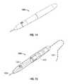
- FIG. 14is a perspective view of a hand-held ultrasonic cutting pen device to be connected to a man-portable, control and power supply assembly in accordance with an embodiment of the present disclosure
- FIG. 15is a perspective view of the hand-held ultrasonic cutting pen device of FIG. 15 with a left-half shell removed;
- FIG. 16is a perspective view of a portable, control and power supply assembly to be connected to a hand-held ultrasonic cutting pen device in accordance with an embodiment of the present disclosure
- FIG. 17is a schematic of an ultrasonic generator in accordance with an embodiment of the present disclosure.
- FIG. 18is a schematic of an ultrasonic generator in accordance with an embodiment of the present disclosure.
- FIG. 19is a schematic of an ultrasonic generator in accordance with an embodiment of the present disclosure.
- distalrefers to that portion of the instrument, or component thereof which is further from the user while the term “proximal” refers to that portion of the instrument or component thereof which is closer to the user.
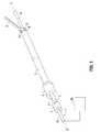
- a surgical toolin this case an ultrasonic surgical haemostatic tool, comprises an elongate waveguide 1 for ultrasonic vibrations (torsional mode ultrasonic vibrations are preferred, although longitudinal mode ultrasonic vibrations may also be utilized).
- An example of such an ultrasonic surgical deviceis disclosed in United States Patent Number 7,520,865 to Young et al . currently owned by and assigned to Covidien AG, the entire contents of which are incorporated herein by reference.
- the waveguide 1defines a longitudinal axis of the tool, as shown by dotted line 2-2.
- a proximal end la of the waveguide 1is mounted to an ultrasonic vibration generator 20 which will be described in more detail hereinbelow.
- the waveguide Iis disposed coaxially within an elongate carrier tube 3, which is mounted at its proximal end to a cylindrical turning element 4.
- the carrier tube 3 and the turning element 4are rotatable as a unit about the longitudinal axis 2, in the sense of arrows 5.
- the turning element 4is acted on by a trigger mechanism or other manual operating means, as detailed below.
- a jaw member 6is mounted pivotably to a distal end 3b of the carrier tube 3.
- a plurality of spacersmay be provided between the waveguide 1 and an inner wall of the carrier tube 3, insulating the carrier tube 3 from ultrasonic vibrations transmitted by the waveguide 1 and maintaining their relative disposition.
- An outer tube 7is disposed coaxially around the carrier tube 3 and the waveguide 1.
- the outer tube 7is mounted at its proximal end to a mounting block 8, which is mounted non-rotatably to a handset of the tool (not shown in this Figure).
- the outer tube 7is provided with a guide lobe 9, which bears on a rearward facing contact surface 10 of the jaw member 6.
- the turning element 4 and the mounting block 8are biased apart, for example with a spring, other resilient device, or cam means such that the guide lobe 9 and the contact surface 10 remain co-operatingly in contact one with another.
- the outer tube 7also acts as a protective sheath for the greater part of the rotatable carrier tube 3 and the waveguide 1, for example protecting them from body fluids as far as possible.
- the carrier tube 3 and the outer tube 7are detachable from the handset of the tool. The carrier tube 3 and the jaw member 6 that it carries may then be withdrawn in a distal direction from the outer tube 7, so that each may be cleaned and sterilized separately before re-use, or alternatively so that either or both may be disposed of and replaced with a fresh equivalent.
- FIG. 2shows a part of the handset of the tool, together with proximal portions of the outer tube 7 and the carrier tube 3.
- the mounting block 8is mounted, permanently or removably, to a handset casing 11.
- the turning element 4is provided with a part helical slot 12 in its cylindrical wall, which is adapted to receive a driving stud (not shown) mounted to a trigger mechanism (not shown) which extends out of the casing 11 through an aperture 13 provided therefor.
- the trigger mechanismmay optionally be mounted to a pivot mounting 14 on the casing 11, as shown, or to a pivot mounting disposed adjacent the aperture 13.
- Pivoting movement of the trigger mechanismwhich is configured to be grasped by a hand of a user, moves the driving stud in a generally longitudinal direction.
- a forward motion of the studcauses the turning element 4, and hence the carrier tube 3, to rotate in an anticlockwise sense (viewed from a proximal end of the tool) and a rearward motion of the stud causes the turning element 4 and the carrier tube 3 to rotate in a clockwise sense.
- the ultrasonic vibration generatoris conveniently mounted inside a detachable element of the casing 11.
- FIG. 2shows the handset with that element detached, and the waveguide 1, mounted to the ultrasonic generator, thereby withdrawn from its operating disposition disposed coaxially within the carrier tube 3.
- Ultrasonic device 100is illustrated in FIG. 3 .
- Ultrasonic device 100is adapted for use in an ultrasonic surgical system having an ultrasonic handpiece.
- An example of such an ultrasonic surgical systemis disclosed in United States Patent Number 6,214,017 to Stoddard et al . currently owned by and assigned to Sherwood Services AG, the entire contents of which are incorporated herein by reference.
- ultrasonic device 100may be adapted for use with the ultrasonic surgical system disclosed in United States Patent Number 4,063,557 to Wuchinich et al. , the entire contents of which are incorporated herein by reference.
- ultrasonic device 100includes an adapter 130 having a first or proximal end 172 and a second or distal end 174. Extending from proximal end 172, adapter 130 includes a fillet 132, a nut 134 and a flange 136 terminating at distal end 174. Flange 136 includes a leading edge 138. Proximal end 172 of adapter 130 is configured to connect ultrasonic device 100 to an ultrasonic handpiece or resonator 150 via a connecting portion 140. Connecting portion 140 is capable of coupling ultrasonic device 100 and connecting portion 140 to ultrasonic handpiece or resonator 150.
- Ultrasonic device 100includes an elongated member 110 having a first or proximal end which coincides with distal end 174 of adapter 130.
- Elongated member 110has a second or distal end 180, and distal end 174 of adapter 130 is joined, in one embodiment unitarily, to the coinciding proximal end of elongated member 110.
- Distal end 180 of elongated member 110is configured as a tip lead 120.
- Tip lead 120extends from a first or proximal end, as is discussed in more detail below.
- Connecting portion 140includes a first or proximal end 142 which is configured to connect to a resonator 150 at a distal end thereof.
- Resonator 150includes, in one embodiment, a magnetostrictive transducer, although other transducer types can be included such as a piezoelectric transducer.
- Resonator 150is supplied power from ultrasonic generator 200 (described in more detail below) such that resonator 150 operates at a desired frequency.
- ultrasonic device 100is made of titanium, although other materials such as stainless steel can be used.
- an internal channel 160is formed within elongated member 110.
- the channelterminates in the connecting body, and does not continue in the resonator.
- the resonatoris typically a laminated core-stack of Permanickel.
- the central channelsupports aspiration suction of tissue.
- the channelalso affords greater mechanical gain because the gain is dependent on the reduction in area ratio of the thin walls.
- the primary purpose of the channelis to support gain for bone tips with the chisel/awl distal ends.
- the internal channels of the bone abrading tips in the disclosure shown and described belowwould also aid in cooling, where irrigation liquid is suctioned via the internal diameter channel.
- Surgical procedures on bonetypically employ an auxiliary suction tube to remove the larger volumes of irrigation liquid and bone debris.
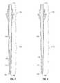
- FIG. 8is a top view of ultrasonic device 100 of FIG. 3 with channel 160 shown in phantom formed within elongated member 110.
- FIG. 6is a side view of ultrasonic device 100 of FIG. 3 with channel 160 in phantom formed within elongated member 110.
- FIG. 7is a cross-sectional view of ultrasonic surgical device 100 of FIG. 5 showing channel 160 formed within elongated member 110.
- FIG. 8is a cross-sectional view of ultrasonic surgical device 100 of FIG. 6 again showing channel 160 formed within elongated member 110.
- Internal channel 160is formed within adapter 130 and elongated member 110 of ultrasonic device 100.
- Elongated member 110is tapered such that the cross-sectional area is a maximum at proximal end 174 interfacing with adapter 130 and is a minimum at proximal end 178 of tip lead 120.
- Channel 160is a substantially constant diameter central hole of diameter d 1 formed within elongated member 110 to enable enhanced mechanical gain in device 100. In the case of a device with a channel, it is the area ratio of the cross-sectional area based on the outer diameter of the elongated member 110 near the leading edge 138 of flange 136 versus the cross-sectional area based on the outer diameter of the elongated member 110 at the distal end 176.
- the area ratio along the length L of the deviceis decreased towards tip lead 120 at the distal end of elongated member 110, and velocity and elongation of the titanium particles are increased.
- the ultrasonic waveis supported by particle motion in the titanium.
- the particlesvibrate about their neutral position in a longitudinal or extensional wave.
- the particlesdo not move along the length of the device, but only vibrate, just as a cork or bobber shows that a wave passes through water via the liquid.
- the displacement of the end of the deviceis due to strain along the device. All the particles supporting the wave are moving at the same resonant frequency. The greater the strain, the greater the velocity of the particles necessary to maintain the same frequency.
- distal end 180 of tip lead 120has a semi-circular plantar surface configuration 122, such that distal end 180 of ultrasonic device 100 is in the form of a chisel and an awl.
- Awlsare utilized in manual boring of holes, such as in boring leather or wood).
- Tip 180 of ultrasonic device 100is blunt or dull.
- the boring of holes with device 100is better facilitated with slightly semi-circular manual motion; however plunge cuts in bone and wood have been accomplished with just longitudinal motion of device 100.
- the combination of the chisel and awl distal end 180 of device 100supports defined cutting or abrasion of sections, planes, notches, grooves, and holes in bone.
- Channel or central hole 160extends from proximal end 172 of adapter 130 to approximately distal end 176 which coincides with proximal end of solid portion 114 of elongated member 110.
- an ultrasonic surgical device 900in accordance with an embodiment of the present disclosure is depicted.
- an ultrasonic-movement-generation assembly 902When an ultrasonic-movement-generation assembly 902 is coupled to a handle 914, the transducer 916 is caused to be realeasably physically coupled to a waveguide 904, 908 through the transducer attachment port 918 and waveguide attachment port 920.
- the transducer assembly 916can be temporarily locked into a fixed rotational position so that the waveguide 904 can be attached to the threads (not shown) with sufficient force. This physical coupling between the waveguide 904 and the transducer assembly 916 allows the transducer assembly 916 to impart movement to the waveguide 904 when power is applied to the transducer assembly 916.
- the device 900has a spindle 906 that attaches to the waveguide 908.
- the spindle 906has indentions that allow a surgeon to easily rotate the spindle 906 and, therefore, the attached waveguide 908 and transducer assembly 916 that is attached to the waveguide 908.
- Such a configurationis useful for obtaining the proper cutting-blade angle during surgery.
- the transducer assembly 916is able to rotate freely within the transducer housing 910.
- the transducer assembly 916is located inside the housing 910 where it cannot be readily secured by the operator, for example, by holding it steady by hand when the waveguide 908 is being secured--the ultrasonic-movement-generation assembly 902 is provided with a button (not shown) that slides into a recess in the housing 910 or, alternatively, by fixing the rotation of the transducer assembly 916 at a maximum rotational angle so that, once the maximum rotation is reached, for example, 360 degrees of rotation, no additional rotation is possible and the waveguide 904 can be screwed thereon. A maximum rotation in the opposite direction will allow the waveguide 904 to be removed as well.
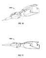
- FIGS. 10 to 12illustrate an entirely hand-held and fully self-contained cautery and cutting device 1000.
- This cutting device 1000reduces the size of the power supply 1002 considerably.
- the waveguide 1004is reduced in length.
- the ultrasonic generator and the power supply 1002reside at the handpiece 1010.
- the pen shaped device shown in FIGS. 10 to 12could have, in accordance with one embodiment, a sealed body 1002, where the body 1002 housing the ultrasonic generator and the power supply 1002 is autoclavable and the waveguide 1004 is simply replaced for each procedure.
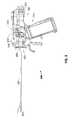
- FIG. 13depicts another shape for the cautery/cutting device 1300 that is shaped to fit into a surgeon's hand for ease of use.
- Another shape for the pen device 1500is shown in FIGS. 14 and 15 and is similar to a writing pen so that the surgery can be carried out with the device 1500 to approximate writing--a process that is comfortable to most physicians.
- the pen 1300, 1500includes all of the transducer components--the transducer 1302, 1502, the protective cannula 1304, 1504, and the waveguide 1306, 1506.
- the base 1600shown in FIG. 16 , has a body 1606 that houses a self-contained power source (i.e., a battery) and a generator circuit operable to generate an output waveform and is sized to be handheld.
- the base 1600is connected through a communications and power tether cord 1602, illustrated diagrammatically in the figures with a dashed line, to the pen-shaped ultrasonic waveguide handle 1500, shown in FIGS. 15-16 .
- the transducer 1502 within the handle 1500is driven by a plurality of driving waves output from the waveform generator within the body 1506.
- the base 1600has a user interface 1604 that can be used to communicate data and carry out functions of the device, such as testing and operation. Through the user interface 1604, the device can be tested in the sealed package without even opening the package. For instance, in one embodiment, a user can press one or more non-illustrated buttons (physical or electronic) in a given sequence (e.g., 5 times in a row) and, thereby, cause the user interface 1604 to display a status of the battery and/or a status of the logic circuitry, all without having to remove it from the sealed package. This is helpful in case of a defect, such as a bad battery, as the purchaser would be able to return the device to the manufacturer before use and, thereby, prove non-use of the device to receive credit. In this embodiment, all of the ultrasonic generator components reside in the base 1600.
- the base 1600is also provided with a non-illustrated clothing attachment mechanism that can be a simple belt clip, or any other way of attaching a device to a wearer.
- the clothing attachment mechanismallows a surgeon or nurse to wear the base 1600 during a surgery so that the cord 1602 will always be of sufficient length, i.e., as long as his arm can reach, no matter where the surgeon is standing.
- an apparatus or ultrasonic generator 1700is provided which is configured to supply power to the resonator 150.
- Ultrasonic generator 1700uses a negative feedback loop to control the output of the ultrasonic generator 1700.
- Ultrasonic generator 1700includes a controllable drive signal generator 1702 that generates a drive signal (A ds ) to control the ultrasonic device.
- the drive signal generator 1702outputs a sine wave in an embodiment of the present disclosure.
- the sine wavemay also be substituted with a square wave, triangular wave or a pulse width modulated (PWM) form of the sine wave.
- Noise generator 1704is also provided which outputs a controllable noise signal (A ns ).
- the ultrasonic devicetends to self heat which would increase resonance.
- the added load at the distal tip of the devicewill add mass and/or compliance, which will also change the resonance.
- the resonancechanges quickly as the ultrasonic device cools again or is transiently loaded and unloaded.
- a noise signalsuch as a "pink" noise or narrowband white noise
- FFTFast Fourier Transform
- a FFTis an efficient algorithm to compute the discrete Fourier transform (DFT) and its inverse.
- DFTdecomposes a sequence of values into components of different frequencies. This operation is useful in many fields but computing it directly from the definition is often too slow to be practical.
- An FFTis a way to compute the same result more quickly: computing a DFT of N points in the obvious way, using the definition, takes O( N 2 ) arithmetical operations, while an FFT can compute the same result in only O(N log N) operations.
- the difference in speedcan be substantial, especially for long data sets where N may be in the thousands or millions-in practice, the computation time can be reduced by several orders of magnitude in such cases, and the improvement is roughly proportional to N /log( N ).
- a pseudo random noise sequencemay be provided as a noise signal by noise signal generator 1704.
- PRNS noise signalallows the ultrasonic system to determine the phase of an output signal with respect to the input signal.
- the drive signal and noise signalare combined (A dns ) by adder 1706 and the combined signal is provided to amplifier 1708.
- Amplifier 1708has a gain "k” which can be a predetermined value set by the manufacturer or could be adjusted by a user of the ultrasonic system.
- the output of amplifier 1708is provided to the ultrasonic device 100 as described above.
- Ultrasonic devicehas a transfer function "G" that determines the resonance and electromechanical gain of the device as described above.
- Ultrasonic deviceoutputs an ultrasonic signal (A out ) proportional to the stroke or mechanical force produced by the ultrasonic device that is to be controlled by the negative feedback loop.
- Controller 1710also receives or has a priori information on the statistics of the noise signal from noise signal generator 1704, the drive signal from drive signal generator 1702, and the gain "k" from amplifier 1708. Controller 1710 may be any available processor or logic circuit configured to perform the functions described below. Controller 1710 may also include a memory configured to store predetermine or measured parameters to use in the controller's 1710 operations. Although not shown, controller 1710 may be coupled to an input device, such as a keypad, keyboard, mouse, touch screen, scanner, or the like. Controller 1710 may also be coupled to an output device such as any type of display that provides a visual indication such as a monitor, light emitting diode display, liquid crystal display, printer, or the like.
- controller 1710applies a transfer function using the FFT's of the ultrasonic signal output and the noise signal from noise signal generator 1704. More specifically, the controller 1710 calculates the new transfer function estimate "G" of the ultrasonic device by dividing the average of the output power FFT's
- the controller 1710can also determine the phase difference between the output power signal and the combined signal by time aligning the noise signal from noise signal generator 1704 and the noise signal in the output power signal.
- the phase differencemay also be determined using a phase-locked loop (PLL) circuit (not shown).
- PLLphase-locked loop
- Drive signal generator 1702is adjusted by the controller 1710 to provide a new drive signal based on the new equivalent resonance frequency.
- FIG. 18depicts another embodiment of an ultrasonic generator 1800 in accordance with the present disclosure.
- a drive signal generator 1802provides a drive signal to amplifier 1804.
- Amplifier 1804may be a non-linear amplifier such as Class D amplifier.
- a Class D amplifieris an electronic amplifier which, in contrast to the active resistance used in linear mode AB-class amplifiers, uses the switching mode of transistors to regulate power delivery. The amplifier, therefore, features high power efficiency (low energy losses), which additionally results in lower weight by eliminating bulky heat sinks. Additionally, if voltage conversion is necessary, the on-the-way high switching frequency allows the bulky audio transformers to be replaced by small inductors. Low pass LC-filtering smoothes the pulses out and restores the signal shape on the load.
- the output of amplifier 1804is provided to an inductor L1 which is coupled to a primary winding 1812 of a transformer 1810.
- the ultrasonic generator 1800provides a noise signal generator 1806 after the amplifier 1804.
- the noise sourceis coupled to a winding on the primary side 1814 of transformer 1815.
- the secondary winding of 1811 of transformer 1815is coupled to primary winding 1812 of transformer 1810.
- the secondary winding 1816 of transformer 1810is coupled to an LC circuit or resonance circuit 1820 which then provides an output of both the drive signal and the noise signal to a resonator such as resonator 150 of ultrasonic device 100 described hereinabove.
- An LC circuitis a resonant circuit or tuned circuit that consists of an inductor, represented by the letter L, and a capacitor, represented by the letter C. When connected together, an electric current can alternate between them at the circuit's resonant frequency.
- the LC circuitis typically used to compensate for losses in the class D amplifier that may occur due to complex loading effects of the ultrasonic device.
- the output of the ultrasonic deviceis provided to a controller 1830 which calculates the new transfer function estimate "G" of the ultrasonic device by dividing the average of the output power FFT's
- the controller 1830can also determine the phase difference between the output power signal and the combined signal by "time aligning" the noise signal from noise signal generator 1806 and the noise signal in the output power signal. Based on the new transfer function estimate "G", a new equivalent resonance frequency can be determined.
- Drive signal generator 1802is adjusted by the controller 1830 to provide a new drive signal based on the new equivalent resonance frequency.
Landscapes
- Engineering & Computer Science (AREA)
- Health & Medical Sciences (AREA)
- Mechanical Engineering (AREA)
- Nuclear Medicine, Radiotherapy & Molecular Imaging (AREA)
- Signal Processing (AREA)
- Biomedical Technology (AREA)
- Computer Networks & Wireless Communication (AREA)
- Radiology & Medical Imaging (AREA)
- Life Sciences & Earth Sciences (AREA)
- Animal Behavior & Ethology (AREA)
- General Health & Medical Sciences (AREA)
- Public Health (AREA)
- Veterinary Medicine (AREA)
- Surgical Instruments (AREA)
Abstract
Description
- The present disclosure relates to an ultrasonic surgical system. More particularly, but not exclusively, it relates to an ultrasonic surgical system able to achieve precise control of a desired operating point.
- Devices which effectively utilize ultrasonic energy for a variety of applications are well-known in a number of diverse arts. A laparoscopic tool where the surgeon may use a scissors-type, a pistol or trigger type grip outside the body to operate a manipulative, gripping or clamping mechanism at a distal end of the tool within the body is useful for use with ultrasonically operated haemostatic cutting tools. Such haemostatic cutting tools are known from British Patent Number
2333709B PCT/GB99/00162 PCT/GBOO/01580 U.S. Pat. No. 5,322,055 . - Each of the above identified patents and patent applications describes a surgical tool comprising means to generate ultrasonic vibrations and a waveguide, operatively connected at a proximal end to said generating means, and provided at a distal end with cutting and/or coagulating means. Each tool is provided with a jaw to hold tissue to be treated in contact with the ultrasonically vibrating cutting and/or coagulating means.
- The Ampulla (Gaussian) profile was published by Kleesattel (as early as 1962), and is employed as a basis for many ultrasonic devices in surgical applications including devices patented and commercialized by Cavitron and Valleylab (patents by Wuchinich, et al., 1977, Stoddard. et al., 2001) for use in ultrasonic aspiration. The Gaussian profile is used in practice to establish and control the resonance and mechanical gain of devices. A resonator, a connecting body and the device act together as a three-body system to provide a mechanical gain, which is defined as the ratio of output stroke amplitude of the radiating tip to the input amplitude of the resonator. The mechanical gain is the result of the strain induced in the materials of which the resonator, the connecting body and the ultrasonic device are composed.
- The magnetostrictive transducer coupled with the connecting body functions as the first stage of the booster device with a mechanical gain of about 2:1, due to the reduction in area ratio of the wall of the complex geometry. The major diameter of the device transitions to the large diameter of the Gaussian in a stepped device geometry with a gain of as large as about 5:1, again due to reduction in area ratio. The mechanical gain increases in the Gaussian due to the Square Root of (1+2*Ln (Area Ratio)), where Ln is the natural logarithm, or about 2:1 for the devices of interest. The total mechanical gain is the product of these constituents, or as large as 20:1 for this example. Thus, the application of ultrasonically vibrating surgical devices used to fragment and remove unwanted tissue with significant precision and safety has led to the development of a number of valuable surgical procedures. Accordingly, the use of ultrasonic aspirators for the fragmentation and surgical removal of tissue from a body has become known. Initially, the technique of surgical aspiration was applied for the fragmentation and removal of cataract tissue. Later, such techniques were applied with significant success to neurosurgery and other surgical specialties where the application of ultrasonic technology through a handheld device for selectively removing tissue on a layer-by-layer basis with precise control has proven feasible.
- Certain devices known in the art characteristically produce continuous vibrations having substantially constant amplitude at a predetermined frequency (i.e. 20-30 kHz). Certain limitations have emerged in attempts to use such devices in a broad spectrum of surgical procedures. For example, the action of a continuously vibrating tip may not have a desired effect in breaking up certain types of body tissue, bone, etc. Because the ultrasonic frequency is limited by the physical characteristics of the handheld device, only the motion available at the tip provides the needed motion to break up a particular tissue. All interaction with the tissue is at the tip, some being purely mechanical and some being ultrasonic. The devices may have limitations in fragmenting some tissues. The limited focus of such a device may render it ineffective for certain applications due to the vibrations which may be provided by the handheld device. For certain medical procedures, it may be necessary to use multiple hand held devices or it may be necessary to use the same console for powering different handheld devices.
- Certain devices known in the art characteristically produce continuous vibrations having a substantially constant amplitude at a frequency of about twenty to about thirty kHz up to about forty to about fifty kHz. The amplitude is inversely proportional to frequency and directly proportional to wavelength because the higher frequency transducers generally have less powerful resonators. For example,
U.S. Patent Nos. 4,063,557 ,4,223,676 and4,425,115 disclose devices suitable for the removal of soft tissue which are particularly adapted for removing highly compliant elastic tissue mixed with blood. Such devices are adapted to be continuously operated when the surgeon wishes to fragment and remove tissue. - A known instrument for the ultrasonic fragmentation of tissue at an operation site and aspiration of the tissue particles and fluid away from the site is the CUSA™ 200 System Ultrasonic Aspirator; see also
U.S. Patent No. 4,827,911 , now sold as the CUSA Excel™. When the longitudinally vibrating tip in such an aspirator is brought into contact with tissue, it gently, selectively and precisely fragments and removes the tissue. Depending on the reserve power of the transducer, the CUSA transducer amplitude can be adjusted independently of the frequency. In simple harmonic motion devices, the frequency is independent of amplitude. Advantages of this unique surgical instrument include minimal damage to healthy tissue in a tumor removal procedure, skeletoning of blood vessels, prompt healing of tissue, minimal heating or tearing of margins of surrounding tissue, minimal pulling of healthy tissue, and excellent tactile feedback for selectively controlled tissue fragmentation and removal. - In many surgical procedures where ultrasonic fragmentation instruments are employed, additional instruments are required for tissue cutting and hemostasis at the operation site. For example, hemostasis is needed in desiccation techniques for deep coagulation to dry out large volumes of tissue and also in fulguration techniques for spray coagulation to dry out the surface of tissues.
- The apparatus disclosed in
U.S. Patent Nos. 4,931,047 and5,015,227 provide hemostasis in combination with an ultrasonically vibrating surgical fragmentation instrument and aspirator. The apparatus effectively provide both a coagulation capability and an enhanced ability to fragment and aspirate tissue in a manner which reduces trauma to surrounding tissue. U.S. Patent No. 4,750,488 and its two continuation Patents,4,750,901 and4,922,902 , disclose methods and apparatus which utilize a combination of ultrasonic fragmentation, aspiration and cauterization.- In
U.S. Patent 5,462,522 , there is disclosed, an ultrasonic therapeutic apparatus. The apparatus includes a water supply unit for supplying cooling water to cool the probe; a suction unit for removing waste matter by suction from the organic tissue treated by means of the cooling water and the probe; an ultrasonic output setting section for setting a preset value for an ultrasonic output from the ultrasonic vibrator; a feedwater output setting section for setting a preset value for a feedwater output from the water supply unit; and a feedwater output control section for controlling the feedwater output setting by the feedwater output setting section so that the preset feedwater output value is a value such that the probe is cooled and is not excessively heated. - In
U.S. Published Application 2009/0143805 A1 , there is disclosed, cutting instruments that utilize ultrasonic waves generate vibrations with an ultrasonic transducer along a longitudinal axis of a cutting blade. By placing a resonant wave along the length of the blade, high-speed longitudinal mechanical movement is produced at the end of the blade. These instruments are advantageous because the mechanical vibrations transmitted to the end of the blade are very effective at cutting organic tissue and, simultaneously, coagulate the tissue using the heat energy produced by the ultrasonic frequencies. Such instruments are particularly well suited for use in minimally invasive procedures, such as endoscopic or laparoscopic procedures, where the blade is passed through a trocar to reach the surgical site. - In an apparatus which fragments, cuts or coagulate tissue by the ultrasonic vibration of a tool tip, it is desirable, for optimum efficiency and energy utilization, that the transducer which provides the ultrasonic vibration operate at resonant frequency. The transducer design establishes the resonant frequency of the system, while the generator tracks the resonant frequency. The generator produces the electrical driving signal to vibrate the transducer at resonant frequency. However, changes in operational parameters, such as, changes in temperature, thermal expansion and load impendance, result in deviations in the resonant frequency.
- More specifically, as the temperature increases, the material density decreases and the speed of sound increases. The increase in temperature may lead to a lower equivalent mass of the key system components, especially the device which has a very low mass and can heat up and cool down quickly. The lower equivalent mass may lead to a change in equivalent resonant frequency. Additionally, when the water supply unit supplies water to cool down the device, the water adds mass to the device as well as acting as a coolant to maintain the temperature of the device. As such, the presence of water may change the equivalent resonant frequency.
- The present disclosure relates to an ultrasonic system that includes an ultrasonic device configured to impart ultrasonic energy to tissue. The system also includes an ultrasonic generator configured to supply power to the ultrasonic device. The ultrasonic generator has a controllable drive signal generator as part of a negative feedback loop configured to provide a drive signal, a controllable noise signal generator configure to provide a noise signal, and a controller. The controller receives an output signal from the ultrasonic device and the noise signal from the noise signal generator, calculates a transfer function estimate based on the output signal and the noise signal, and adjusts the drive signal generator based on the calculated transfer function estimate.
- In another embodiment according to the present disclosure, an ultrasonic generator configured to supply power to an ultrasonic device is provided. The ultrasonic generator has a drive signal generator configured to provide a drive signal, a noise signal generator configured to provide a noise signal, and an adder configured to combine the drive signal and the noise signal. The ultrasonic generator also includes an amplifier having a gain configured to amplify the combined signal. A controller is configured to receive an output signal from the ultrasonic device and the noise signal from the noise signal generator, calculate a transfer function estimate based on the output signal, the noise signal and the gain, and adjust the drive signal generator based on the calculated transfer function estimate.
- In yet another embodiment according to the present disclosure, an ultrasonic generator configured to supply power to an ultrasonic device is provided. The ultrasonic generator has a drive signal generator configured to provide a drive signal, an amplifier having a gain configured to amplify the drive signal, a noise signal generator configured to provide a noise signal, and a resonance circuit configured to provide an output to the resonator of the ultrasonic device. The ultrasonic generator also includes a transformer having a first primary winding coupled to the amplifier, a second primary winding coupled to the noise signal generator and a secondary winding coupled to the resonance circuit. A controller is also provided that is configured to receive an output signal from the ultrasonic device and the noise signal from the noise signal generator, calculate a transfer function estimate based on the output signal and the noise signal, and adjust the drive signal generator based on the calculated transfer function estimate.
- The above and other aspects, features, and advantages of the present disclosure will become more apparent in light of the following detailed description when taken in conjunction with the accompanying drawings in which:
FIG. 1 is a perspective view of an ultrasonic device in accordance with an embodiment of the present disclosure;FIG. 2 is a cross-sectional view of a part of the handset of the tool ofFIG. 1 . including a turning element;FIG. 3 is a perspective view of an ultrasonic device in accordance with an embodiment of the present disclosure;FIG. 4 is an enlarged view of a tip of the ultrasonic device ofFIG. 3 ;FIG. 5 is a top view of the ultrasonic device ofFIG. 3 with a channel shown in phantom;FIG. 6 is a side view of the ultrasonic device ofFIG. 3 ;FIG. 7 is a cross-sectional view of the ultrasonic surgical device ofFIG. 5 ;FIG. 8 is a cross-sectional view of the ultrasonic surgical device ofFIG. 6 ;FIG. 9 is a side elevational view of an exemplary handle with the left-side shell removed in accordance with an embodiment of the present disclosure;FIG. 10 is a perspective view from the front left side of a hand-held ultrasonic cutting pen device in accordance with an embodiment of the present disclosure;- ]
FIG. 11 is a side elevational view of the hand-held ultrasonic cutting pen device ofFIG. 10 from the left side; FIG. 12 is a side elevational view of the hand-held ultrasonic cutting pen device ofFIG. 11 with the left-side shell removed;FIG. 13 is a diagrammatic illustration of a hand-held ultrasonic cutting pen device to be connected to a man-portabie, control and power supply assembly in accordance with an embodiment of the present disclosure;FIG. 14 is a perspective view of a hand-held ultrasonic cutting pen device to be connected to a man-portable, control and power supply assembly in accordance with an embodiment of the present disclosure;FIG. 15 is a perspective view of the hand-held ultrasonic cutting pen device ofFIG. 15 with a left-half shell removed;FIG. 16 is a perspective view of a portable, control and power supply assembly to be connected to a hand-held ultrasonic cutting pen device in accordance with an embodiment of the present disclosure;FIG. 17 is a schematic of an ultrasonic generator in accordance with an embodiment of the present disclosure;FIG. 18 is a schematic of an ultrasonic generator in accordance with an embodiment of the present disclosure; and- FIG. 19 is a schematic of an ultrasonic generator in accordance with an embodiment of the present disclosure.
- Particular embodiments of the present disclosure will be described hereinbelow with reference to the accompanying drawings; however, it is to be understood that the disclosed embodiments are merely exemplary of the disclosure, which may be embodied in various forms. Well-known functions or constructions are not described in detail to avoid obscuring the present disclosure in unnecessary detail. Therefore, specific structural and functional details disclosed herein are not to be interpreted as limiting, but merely as a basis for the claims and as a representative basis for teaching one skilled in the art to variously employ the present disclosure in virtually any appropriately detailed structure.
- Embodiments of the presently disclosed ultrasonic surgical system are described in detail with reference to the drawings, in which like reference numerals designate identical or corresponding elements in each of the several views. As used herein, the term "distal" refers to that portion of the instrument, or component thereof which is further from the user while the term "proximal" refers to that portion of the instrument or component thereof which is closer to the user.
- Referring now to the drawings and to
FIG. 1 in particular, a surgical tool, in this case an ultrasonic surgical haemostatic tool, comprises an elongate waveguide 1 for ultrasonic vibrations (torsional mode ultrasonic vibrations are preferred, although longitudinal mode ultrasonic vibrations may also be utilized). An example of such an ultrasonic surgical device is disclosed in United States Patent Number7,520,865 to Young et al . currently owned by and assigned to Covidien AG, the entire contents of which are incorporated herein by reference. The waveguide 1 defines a longitudinal axis of the tool, as shown by dotted line 2-2. A proximal end la of the waveguide 1 is mounted to anultrasonic vibration generator 20 which will be described in more detail hereinbelow. - The waveguide I is disposed coaxially within an elongate carrier tube 3, which is mounted at its proximal end to a
cylindrical turning element 4. The carrier tube 3 and theturning element 4 are rotatable as a unit about thelongitudinal axis 2, in the sense of arrows 5. The turningelement 4 is acted on by a trigger mechanism or other manual operating means, as detailed below. Ajaw member 6 is mounted pivotably to adistal end 3b of the carrier tube 3. - A plurality of spacers (not shown) may be provided between the waveguide 1 and an inner wall of the carrier tube 3, insulating the carrier tube 3 from ultrasonic vibrations transmitted by the waveguide 1 and maintaining their relative disposition.
- An
outer tube 7 is disposed coaxially around the carrier tube 3 and the waveguide 1. Theouter tube 7 is mounted at its proximal end to amounting block 8, which is mounted non-rotatably to a handset of the tool (not shown in this Figure). At its distal end, theouter tube 7 is provided with aguide lobe 9, which bears on a rearward facingcontact surface 10 of thejaw member 6. The turningelement 4 and the mountingblock 8 are biased apart, for example with a spring, other resilient device, or cam means such that theguide lobe 9 and thecontact surface 10 remain co-operatingly in contact one with another. - When the carrier tube 3 is rotated, the
contact surface 10 of thejaw member 6 mounted thereto moves across theguide lobe 9 of the stationaryouter tube 7, thereby causing a pivoting movement of thejaw member 6 away from or towards contact with the distal end 16 of the waveguide 1, as detailed below. - The
outer tube 7 also acts as a protective sheath for the greater part of the rotatable carrier tube 3 and the waveguide 1, for example protecting them from body fluids as far as possible. In a preferred embodiment of the tool, the carrier tube 3 and theouter tube 7 are detachable from the handset of the tool. The carrier tube 3 and thejaw member 6 that it carries may then be withdrawn in a distal direction from theouter tube 7, so that each may be cleaned and sterilized separately before re-use, or alternatively so that either or both may be disposed of and replaced with a fresh equivalent. FIG. 2 shows a part of the handset of the tool, together with proximal portions of theouter tube 7 and the carrier tube 3. The mountingblock 8 is mounted, permanently or removably, to ahandset casing 11. In this particular embodiment of the tool, the turningelement 4 is provided with a parthelical slot 12 in its cylindrical wall, which is adapted to receive a driving stud (not shown) mounted to a trigger mechanism (not shown) which extends out of thecasing 11 through anaperture 13 provided therefor. The trigger mechanism may optionally be mounted to a pivot mounting 14 on thecasing 11, as shown, or to a pivot mounting disposed adjacent theaperture 13. Pivoting movement of the trigger mechanism, which is configured to be grasped by a hand of a user, moves the driving stud in a generally longitudinal direction. As the driving stud is constrained to move within the parthelical slot 12, a forward motion of the stud causes theturning element 4, and hence the carrier tube 3, to rotate in an anticlockwise sense (viewed from a proximal end of the tool) and a rearward motion of the stud causes theturning element 4 and the carrier tube 3 to rotate in a clockwise sense.- The ultrasonic vibration generator is conveniently mounted inside a detachable element of the
casing 11.FIG. 2 shows the handset with that element detached, and the waveguide 1, mounted to the ultrasonic generator, thereby withdrawn from its operating disposition disposed coaxially within the carrier tube 3. - An
ultrasonic device 100, in accordance with one embodiment of the present disclosure, is illustrated inFIG. 3 .Ultrasonic device 100 is adapted for use in an ultrasonic surgical system having an ultrasonic handpiece. An example of such an ultrasonic surgical system is disclosed in United States Patent Number6,214,017 to Stoddard et al . currently owned by and assigned to Sherwood Services AG, the entire contents of which are incorporated herein by reference. Alternatively,ultrasonic device 100 may be adapted for use with the ultrasonic surgical system disclosed in United States Patent Number4,063,557 to Wuchinich et al. , the entire contents of which are incorporated herein by reference. - Referring to
FIGS. 3 and 4 , in one embodiment of the present disclosure,ultrasonic device 100 includes anadapter 130 having a first orproximal end 172 and a second ordistal end 174. Extending fromproximal end 172,adapter 130 includes a fillet 132, a nut 134 and a flange 136 terminating atdistal end 174. Flange 136 includes a leading edge 138.Proximal end 172 ofadapter 130 is configured to connectultrasonic device 100 to an ultrasonic handpiece orresonator 150 via a connectingportion 140. Connectingportion 140 is capable of couplingultrasonic device 100 and connectingportion 140 to ultrasonic handpiece orresonator 150. As used herein, the term "resonator" is used to refer to what is often referred to in the literature as an ultrasonic handpiece.Ultrasonic device 100 includes anelongated member 110 having a first or proximal end which coincides withdistal end 174 ofadapter 130.Elongated member 110 has a second ordistal end 180, anddistal end 174 ofadapter 130 is joined, in one embodiment unitarily, to the coinciding proximal end ofelongated member 110.Distal end 180 ofelongated member 110 is configured as atip lead 120.Tip lead 120 extends from a first or proximal end, as is discussed in more detail below. - Connecting
portion 140 includes a first orproximal end 142 which is configured to connect to aresonator 150 at a distal end thereof.Resonator 150 includes, in one embodiment, a magnetostrictive transducer, although other transducer types can be included such as a piezoelectric transducer.Resonator 150 is supplied power from ultrasonic generator 200 (described in more detail below) such thatresonator 150 operates at a desired frequency. In one embodiment,ultrasonic device 100 is made of titanium, although other materials such as stainless steel can be used. - As seen in
FIG. 5 , aninternal channel 160 is formed withinelongated member 110. As is known in the art, the channel terminates in the connecting body, and does not continue in the resonator. The resonator is typically a laminated core-stack of Permanickel. In most implementations, the central channel supports aspiration suction of tissue. The channel also affords greater mechanical gain because the gain is dependent on the reduction in area ratio of the thin walls. The primary purpose of the channel is to support gain for bone tips with the chisel/awl distal ends. The internal channels of the bone abrading tips in the disclosure shown and described below would also aid in cooling, where irrigation liquid is suctioned via the internal diameter channel. Surgical procedures on bone typically employ an auxiliary suction tube to remove the larger volumes of irrigation liquid and bone debris. - Referring to
FIGS. 5-6 ,FIG. 8 is a top view ofultrasonic device 100 ofFIG. 3 withchannel 160 shown in phantom formed withinelongated member 110.FIG. 6 is a side view ofultrasonic device 100 ofFIG. 3 withchannel 160 in phantom formed withinelongated member 110.FIG. 7 is a cross-sectional view of ultrasonicsurgical device 100 ofFIG. 5 showing channel 160 formed withinelongated member 110.FIG. 8 is a cross-sectional view of ultrasonicsurgical device 100 ofFIG. 6 again showingchannel 160 formed withinelongated member 110.Internal channel 160 is formed withinadapter 130 andelongated member 110 ofultrasonic device 100. Elongated member 110 is tapered such that the cross-sectional area is a maximum atproximal end 174 interfacing withadapter 130 and is a minimum atproximal end 178 oftip lead 120.Channel 160 is a substantially constant diameter central hole of diameter d1 formed withinelongated member 110 to enable enhanced mechanical gain indevice 100. In the case of a device with a channel, it is the area ratio of the cross-sectional area based on the outer diameter of theelongated member 110 near the leading edge 138 of flange 136 versus the cross-sectional area based on the outer diameter of theelongated member 110 at thedistal end 176. The area ratio along the length L of the device is decreased towardstip lead 120 at the distal end ofelongated member 110, and velocity and elongation of the titanium particles are increased. The ultrasonic wave is supported by particle motion in the titanium. The particles vibrate about their neutral position in a longitudinal or extensional wave. The particles do not move along the length of the device, but only vibrate, just as a cork or bobber shows that a wave passes through water via the liquid. As the device wall thickness decreases, more strain occurs in the metal as the particles move a greater distance about their neutral position. The displacement of the end of the device is due to strain along the device. All the particles supporting the wave are moving at the same resonant frequency. The greater the strain, the greater the velocity of the particles necessary to maintain the same frequency.- As best illustrated in
FIG. 4 ,distal end 180 oftip lead 120 has a semi-circularplantar surface configuration 122, such thatdistal end 180 ofultrasonic device 100 is in the form of a chisel and an awl. (Awls are utilized in manual boring of holes, such as in boring leather or wood).Tip 180 ofultrasonic device 100 is blunt or dull. The boring of holes withdevice 100 is better facilitated with slightly semi-circular manual motion; however plunge cuts in bone and wood have been accomplished with just longitudinal motion ofdevice 100. The combination of the chisel and awldistal end 180 ofdevice 100 supports defined cutting or abrasion of sections, planes, notches, grooves, and holes in bone. Channel orcentral hole 160 extends fromproximal end 172 ofadapter 130 to approximatelydistal end 176 which coincides with proximal end ofsolid portion 114 ofelongated member 110. - Another example of an ultrasonic surgical device is disclosed in United States Published Application Number
20090143805 to Palmer et al . currently owned by and assigned to Syntheon, LLC, the entire contents of which are incorporated herein by reference. Referring now toFIG. 9 , an ultrasonicsurgical device 900 in accordance with an embodiment of the present disclosure is depicted. When an ultrasonic-movement-generation assembly 902 is coupled to ahandle 914, thetransducer 916 is caused to be realeasably physically coupled to awaveguide waveguide attachment port 920. It is envisioned that thetransducer assembly 916 can be temporarily locked into a fixed rotational position so that thewaveguide 904 can be attached to the threads (not shown) with sufficient force. This physical coupling between thewaveguide 904 and thetransducer assembly 916 allows thetransducer assembly 916 to impart movement to thewaveguide 904 when power is applied to thetransducer assembly 916. - The
device 900 has aspindle 906 that attaches to thewaveguide 908. Thespindle 906 has indentions that allow a surgeon to easily rotate thespindle 906 and, therefore, the attachedwaveguide 908 andtransducer assembly 916 that is attached to thewaveguide 908. Such a configuration is useful for obtaining the proper cutting-blade angle during surgery. To provide for this rotation, in one embodiment, thetransducer assembly 916 is able to rotate freely within the transducer housing 910. - During initial coupling of the
transducer assembly 916 andwaveguide 904, all that is needed is that one of thetransducer assembly 916 and thewaveguide 904 remains relatively stationary with respect to the other. According to one embodiment of the present disclosure, when thetransducer assembly 916 is located inside the housing 910 where it cannot be readily secured by the operator, for example, by holding it steady by hand when thewaveguide 908 is being secured--the ultrasonic-movement-generation assembly 902 is provided with a button (not shown) that slides into a recess in the housing 910 or, alternatively, by fixing the rotation of thetransducer assembly 916 at a maximum rotational angle so that, once the maximum rotation is reached, for example, 360 degrees of rotation, no additional rotation is possible and thewaveguide 904 can be screwed thereon. A maximum rotation in the opposite direction will allow thewaveguide 904 to be removed as well. - In an alternative exemplary embodiment to the gun device,
FIGS. 10 to 12 illustrate an entirely hand-held and fully self-contained cautery andcutting device 1000. Thiscutting device 1000 reduces the size of thepower supply 1002 considerably. Here, in comparison to the previous embodiments, thewaveguide 1004 is reduced in length. The ultrasonic generator and thepower supply 1002 reside at thehandpiece 1010. As in the other embodiments described above, the pen shaped device shown inFIGS. 10 to 12 could have, in accordance with one embodiment, a sealedbody 1002, where thebody 1002 housing the ultrasonic generator and thepower supply 1002 is autoclavable and thewaveguide 1004 is simply replaced for each procedure. FIG. 13 depicts another shape for the cautery/cutting device 1300 that is shaped to fit into a surgeon's hand for ease of use. Another shape for thepen device 1500 is shown inFIGS. 14 and 15 and is similar to a writing pen so that the surgery can be carried out with thedevice 1500 to approximate writing--a process that is comfortable to most physicians. Thepen transducer protective cannula waveguide - In these embodiments, the
base 1600, shown inFIG. 16 , has abody 1606 that houses a self-contained power source (i.e., a battery) and a generator circuit operable to generate an output waveform and is sized to be handheld. Thebase 1600 is connected through a communications andpower tether cord 1602, illustrated diagrammatically in the figures with a dashed line, to the pen-shapedultrasonic waveguide handle 1500, shown inFIGS. 15-16 . When in operation, thetransducer 1502 within thehandle 1500 is driven by a plurality of driving waves output from the waveform generator within thebody 1506. - The
base 1600 has auser interface 1604 that can be used to communicate data and carry out functions of the device, such as testing and operation. Through theuser interface 1604, the device can be tested in the sealed package without even opening the package. For instance, in one embodiment, a user can press one or more non-illustrated buttons (physical or electronic) in a given sequence (e.g., 5 times in a row) and, thereby, cause theuser interface 1604 to display a status of the battery and/or a status of the logic circuitry, all without having to remove it from the sealed package. This is helpful in case of a defect, such as a bad battery, as the purchaser would be able to return the device to the manufacturer before use and, thereby, prove non-use of the device to receive credit. In this embodiment, all of the ultrasonic generator components reside in thebase 1600. - The
base 1600 is also provided with a non-illustrated clothing attachment mechanism that can be a simple belt clip, or any other way of attaching a device to a wearer. The clothing attachment mechanism allows a surgeon or nurse to wear thebase 1600 during a surgery so that thecord 1602 will always be of sufficient length, i.e., as long as his arm can reach, no matter where the surgeon is standing. - Referring to
FIG. 17 , an apparatus orultrasonic generator 1700 is provided which is configured to supply power to theresonator 150.Ultrasonic generator 1700 uses a negative feedback loop to control the output of theultrasonic generator 1700.Ultrasonic generator 1700 includes a controllabledrive signal generator 1702 that generates a drive signal (Ads) to control the ultrasonic device. Thedrive signal generator 1702 outputs a sine wave in an embodiment of the present disclosure. The sine wave may also be substituted with a square wave, triangular wave or a pulse width modulated (PWM) form of the sine wave.Noise generator 1704 is also provided which outputs a controllable noise signal (Ans). The ultrasonic device tends to self heat which would increase resonance. Alternatively, the added load at the distal tip of the device will add mass and/or compliance, which will also change the resonance. The resonance changes quickly as the ultrasonic device cools again or is transiently loaded and unloaded. By adding a noise signal such as a "pink" noise or narrowband white noise, with many Fast Fourier Transform (FFT) bins averaged together, an operating point can be determined and the ultrasonic device could be tuned to the operating point. A FFT is an efficient algorithm to compute the discrete Fourier transform (DFT) and its inverse. A DFT decomposes a sequence of values into components of different frequencies. This operation is useful in many fields but computing it directly from the definition is often too slow to be practical. An FFT is a way to compute the same result more quickly: computing a DFT ofN points in the obvious way, using the definition, takes O(N2) arithmetical operations, while an FFT can compute the same result in only O(N log N) operations. The difference in speed can be substantial, especially for long data sets where N may be in the thousands or millions-in practice, the computation time can be reduced by several orders of magnitude in such cases, and the improvement is roughly proportional toN/log(N). - In another embodiment of the present disclosure, a pseudo random noise sequence (PRNS) may be provided as a noise signal by
noise signal generator 1704. Using a PRNS noise signal allows the ultrasonic system to determine the phase of an output signal with respect to the input signal. - The drive signal and noise signal are combined (Adns) by
adder 1706 and the combined signal is provided toamplifier 1708.Amplifier 1708 has a gain "k" which can be a predetermined value set by the manufacturer or could be adjusted by a user of the ultrasonic system. The output ofamplifier 1708 is provided to theultrasonic device 100 as described above. Ultrasonic device has a transfer function "G" that determines the resonance and electromechanical gain of the device as described above. Ultrasonic device outputs an ultrasonic signal (Aout) proportional to the stroke or mechanical force produced by the ultrasonic device that is to be controlled by the negative feedback loop. - As shown in
FIG. 17 , the ultrasonic signal is provided to acontroller 1710.Controller 1710 also receives or has a priori information on the statistics of the noise signal fromnoise signal generator 1704, the drive signal fromdrive signal generator 1702, and the gain "k" fromamplifier 1708.Controller 1710 may be any available processor or logic circuit configured to perform the functions described below.Controller 1710 may also include a memory configured to store predetermine or measured parameters to use in the controller's 1710 operations. Although not shown,controller 1710 may be coupled to an input device, such as a keypad, keyboard, mouse, touch screen, scanner, or the like.Controller 1710 may also be coupled to an output device such as any type of display that provides a visual indication such as a monitor, light emitting diode display, liquid crystal display, printer, or the like. - Because the increase in temperature may lead to a lower equivalent mass of the key ultrasonic system components (for instance, in one embodiment, the water supply unit supplies water to cool down the device where the water adds mass to the device as well as acting as a coolant to maintain the temperature of the device), the equivalent resonant frequency of the ultrasonic device may change. Accordingly,
controller 1710 applies a transfer function using the FFT's of the ultrasonic signal output and the noise signal fromnoise signal generator 1704. More specifically, thecontroller 1710 calculates the new transfer function estimate "G" of the ultrasonic device by dividing the average of the output power FFT's |Aout|2 by the input FFT's noise power |Ans|2 and gain "k". Thecontroller 1710 can also determine the phase difference between the output power signal and the combined signal by time aligning the noise signal fromnoise signal generator 1704 and the noise signal in the output power signal. The phase difference may also be determined using a phase-locked loop (PLL) circuit (not shown). Based on the new transfer function estimate "G", a new equivalent resonance frequency can be determined. Drivesignal generator 1702 is adjusted by thecontroller 1710 to provide a new drive signal based on the new equivalent resonance frequency. FIG. 18 depicts another embodiment of an ultrasonic generator 1800 in accordance with the present disclosure. As shown inFIG. 18 , adrive signal generator 1802 provides a drive signal toamplifier 1804.Amplifier 1804 may be a non-linear amplifier such as Class D amplifier. A Class D amplifier is an electronic amplifier which, in contrast to the active resistance used in linear mode AB-class amplifiers, uses the switching mode of transistors to regulate power delivery. The amplifier, therefore, features high power efficiency (low energy losses), which additionally results in lower weight by eliminating bulky heat sinks. Additionally, if voltage conversion is necessary, the on-the-way high switching frequency allows the bulky audio transformers to be replaced by small inductors. Low pass LC-filtering smoothes the pulses out and restores the signal shape on the load.- The output of
amplifier 1804 is provided to an inductor L1 which is coupled to a primary winding 1812 of atransformer 1810. Unlike the embodiment described inFig. 17 , the ultrasonic generator 1800 provides anoise signal generator 1806 after theamplifier 1804. The noise source is coupled to a winding on theprimary side 1814 oftransformer 1815. The secondary winding of 1811 oftransformer 1815 is coupled to primary winding 1812 oftransformer 1810. The secondary winding 1816 oftransformer 1810 is coupled to an LC circuit orresonance circuit 1820 which then provides an output of both the drive signal and the noise signal to a resonator such asresonator 150 ofultrasonic device 100 described hereinabove. An LC circuit is a resonant circuit or tuned circuit that consists of an inductor, represented by the letter L, and a capacitor, represented by the letter C. When connected together, an electric current can alternate between them at the circuit's resonant frequency. The LC circuit is typically used to compensate for losses in the class D amplifier that may occur due to complex loading effects of the ultrasonic device. - Similar to
ultrasonic generator 1700, the output of the ultrasonic device is provided to acontroller 1830 which calculates the new transfer function estimate "G" of the ultrasonic device by dividing the average of the output power FFT's |Aout|2 by the input FFT's noise power |Ans|2. Thecontroller 1830 can also determine the phase difference between the output power signal and the combined signal by "time aligning" the noise signal fromnoise signal generator 1806 and the noise signal in the output power signal. Based on the new transfer function estimate "G", a new equivalent resonance frequency can be determined. Drivesignal generator 1802 is adjusted by thecontroller 1830 to provide a new drive signal based on the new equivalent resonance frequency. - The described embodiments of the present disclosure are intended to be illustrative rather than restrictive, and are not intended to represent every embodiment of the present disclosure. Various modifications and variations can be made without departing from the spirit or scope of the disclosure as set forth in the following claims both literally and in equivalents recognized in law.
Claims (14)
- An ultrasonic system, comprising:an ultrasonic device configured to impart ultrasonic energy to tissue; andan ultrasonic generator configured to supply power to the ultrasonic device, the ultrasonic generator comprising:a controllable drive signal generator configured to provide a drive signal;a controllable noise signal generator configure to provide a noise signal; anda controller configured to:receive an output signal from the ultrasonic device and the noise signal from the noise signal generator,calculate a transfer function estimate based on the output signal and the noise signal, andadjust the drive signal generator based on the calculated transfer function estimate.
- The ultrasonic system according to claim 1, further comprising:an adder configured to combine the drive signal and the noise signal; andan amplifier having a gain, the amplifier configured to amplify the combined drive signal and noise signal and provide the amplified signal to the ultrasonic device.
- The ultrasonic system according to claim 2 wherein the controller uses the gain of the amplifier to calculate the transfer function estimate.
- The ultrasonic system according to claim 1, 2 or 3, wherein the noise signal is pink noise.
- The ultrasonic system according to claim 1, 2 or 3, wherein the noise signal is a narrowband white noise.
- The ultrasonic system according to claim 1, 2 or 3, wherein the noise signal is a pseudo random noise sequence (PRNS).
- The ultrasonic system according to claim 6 wherein the controller determines a phase difference by time aligning a noise signal in the output signal with the noise signal provided by the noise signal generator.
- The ultrasonic system according to claim 2 or 3, wherein the gain is predetermined by a manufacturer.
- The ultrasonic system according to claim 2 or 3, wherein the gain is set by a user.
- The ultrasonic system according to any one of the preceding claims, wherein the controller calculates a Fast Fourier Transform of the output signal and the noise signal to calculate the transfer function estimate.
- An ultrasonic generator configured to supply power to an ultrasonic device, the ultrasonic generator comprising:a drive signal generator configured to provide a drive signal;a noise signal generator configure to provide a noise signal;an adder configured to combine the drive signal and the noise signal;an amplifier having a gain configured to amplify the combined signal; anda controller configured to:receive an output signal from the ultrasonic device and the noise signal from the noise signal generator,calculate a transfer function estimate based on the output signal, the noise signal and the gain, andadjust the drive signal generator based on the calculated transfer function estimate.
- An ultrasonic generator configured to supply power to an ultrasonic device, the ultrasonic generator comprising:a drive signal generator configured to provide a drive signal;an amplifier having a gain configured to amplify the drive signal;a noise signal generator configure to provide a noise signal;a resonance circuit configured to provide an output to the resonator of the ultrasonic device;a transformer having a first primary winding coupled to the amplifier, a second primary winding coupled to the noise signal generator and a secondary winding coupled to the resonance circuit; anda controller configured to:receive an output signal from the ultrasonic device and the noise signal from the noise signal generator,calculate a transfer function estimate based on the output signal and the noise signal, andadjust the drive signal generator based on the calculated transfer function estimate.
- The ultrasonic generator according to claim 12, wherein the resonance circuit is an LC circuit.
- The ultrasonic generator according to claim 12 or 13, wherein the amplifier is a Class D amplifier.
Applications Claiming Priority (1)
| Application Number | Priority Date | Filing Date | Title |
|---|---|---|---|
| US12/561,067US8207651B2 (en) | 2009-09-16 | 2009-09-16 | Low energy or minimum disturbance method for measuring frequency response functions of ultrasonic surgical devices in determining optimum operating point |
Publications (3)
| Publication Number | Publication Date |
|---|---|
| EP2298193A2true EP2298193A2 (en) | 2011-03-23 |
| EP2298193A3 EP2298193A3 (en) | 2011-08-03 |
| EP2298193B1 EP2298193B1 (en) | 2013-05-01 |
Family
ID=43503460
Family Applications (1)
| Application Number | Title | Priority Date | Filing Date |
|---|---|---|---|
| EP10177202.8ACeasedEP2298193B1 (en) | 2009-09-16 | 2010-09-16 | Low energy or minimum disturbance method for measuring frequency response functions of ultrasonic surgical devices in determining optimum operating point |
Country Status (2)
| Country | Link |
|---|---|
| US (3) | US8207651B2 (en) |
| EP (1) | EP2298193B1 (en) |
Cited By (1)
| Publication number | Priority date | Publication date | Assignee | Title |
|---|---|---|---|---|
| EP2995259A4 (en)* | 2013-05-09 | 2017-06-07 | Alpinion Medical Systems Co., Ltd. | Ultrasound optimization method and ultrasonic medical device therefor |
Families Citing this family (165)
| Publication number | Priority date | Publication date | Assignee | Title |
|---|---|---|---|---|
| US7364577B2 (en) | 2002-02-11 | 2008-04-29 | Sherwood Services Ag | Vessel sealing system |
| ES2262639T3 (en) | 2001-04-06 | 2006-12-01 | Sherwood Services Ag | SHUTTER AND DIVIDER OF GLASSES WITH BUMPER MEMBERS N OCONDUCTIVES. |
| US11229472B2 (en) | 2001-06-12 | 2022-01-25 | Cilag Gmbh International | Modular battery powered handheld surgical instrument with multiple magnetic position sensors |
| US7931649B2 (en) | 2002-10-04 | 2011-04-26 | Tyco Healthcare Group Lp | Vessel sealing instrument with electrical cutting mechanism |
| US7367976B2 (en) | 2003-11-17 | 2008-05-06 | Sherwood Services Ag | Bipolar forceps having monopolar extension |
| US7131970B2 (en) | 2003-11-19 | 2006-11-07 | Sherwood Services Ag | Open vessel sealing instrument with cutting mechanism |
| US8182501B2 (en) | 2004-02-27 | 2012-05-22 | Ethicon Endo-Surgery, Inc. | Ultrasonic surgical shears and method for sealing a blood vessel using same |
| US20060079879A1 (en) | 2004-10-08 | 2006-04-13 | Faller Craig N | Actuation mechanism for use with an ultrasonic surgical instrument |
| US7909823B2 (en) | 2005-01-14 | 2011-03-22 | Covidien Ag | Open vessel sealing instrument |
| US7922953B2 (en) | 2005-09-30 | 2011-04-12 | Covidien Ag | Method for manufacturing an end effector assembly |
| US20070191713A1 (en) | 2005-10-14 | 2007-08-16 | Eichmann Stephen E | Ultrasonic device for cutting and coagulating |
| US7621930B2 (en) | 2006-01-20 | 2009-11-24 | Ethicon Endo-Surgery, Inc. | Ultrasound medical instrument having a medical ultrasonic blade |
| US8911460B2 (en) | 2007-03-22 | 2014-12-16 | Ethicon Endo-Surgery, Inc. | Ultrasonic surgical instruments |
| US8142461B2 (en) | 2007-03-22 | 2012-03-27 | Ethicon Endo-Surgery, Inc. | Surgical instruments |
| US8057498B2 (en) | 2007-11-30 | 2011-11-15 | Ethicon Endo-Surgery, Inc. | Ultrasonic surgical instrument blades |
| US8523889B2 (en) | 2007-07-27 | 2013-09-03 | Ethicon Endo-Surgery, Inc. | Ultrasonic end effectors with increased active length |
| US8808319B2 (en) | 2007-07-27 | 2014-08-19 | Ethicon Endo-Surgery, Inc. | Surgical instruments |
| US8882791B2 (en) | 2007-07-27 | 2014-11-11 | Ethicon Endo-Surgery, Inc. | Ultrasonic surgical instruments |
| US9044261B2 (en) | 2007-07-31 | 2015-06-02 | Ethicon Endo-Surgery, Inc. | Temperature controlled ultrasonic surgical instruments |
| US8512365B2 (en) | 2007-07-31 | 2013-08-20 | Ethicon Endo-Surgery, Inc. | Surgical instruments |
| US8430898B2 (en) | 2007-07-31 | 2013-04-30 | Ethicon Endo-Surgery, Inc. | Ultrasonic surgical instruments |
| EP2217157A2 (en) | 2007-10-05 | 2010-08-18 | Ethicon Endo-Surgery, Inc. | Ergonomic surgical instruments |
| US10010339B2 (en) | 2007-11-30 | 2018-07-03 | Ethicon Llc | Ultrasonic surgical blades |
| US9089360B2 (en) | 2008-08-06 | 2015-07-28 | Ethicon Endo-Surgery, Inc. | Devices and techniques for cutting and coagulating tissue |
| US8142473B2 (en) | 2008-10-03 | 2012-03-27 | Tyco Healthcare Group Lp | Method of transferring rotational motion in an articulating surgical instrument |
| US8016827B2 (en) | 2008-10-09 | 2011-09-13 | Tyco Healthcare Group Lp | Apparatus, system, and method for performing an electrosurgical procedure |
| US8114122B2 (en) | 2009-01-13 | 2012-02-14 | Tyco Healthcare Group Lp | Apparatus, system, and method for performing an electrosurgical procedure |
| US8187273B2 (en) | 2009-05-07 | 2012-05-29 | Tyco Healthcare Group Lp | Apparatus, system, and method for performing an electrosurgical procedure |
| US9700339B2 (en) | 2009-05-20 | 2017-07-11 | Ethicon Endo-Surgery, Inc. | Coupling arrangements and methods for attaching tools to ultrasonic surgical instruments |
| US8246618B2 (en) | 2009-07-08 | 2012-08-21 | Tyco Healthcare Group Lp | Electrosurgical jaws with offset knife |
| US8663220B2 (en) | 2009-07-15 | 2014-03-04 | Ethicon Endo-Surgery, Inc. | Ultrasonic surgical instruments |
| US8133254B2 (en) | 2009-09-18 | 2012-03-13 | Tyco Healthcare Group Lp | In vivo attachable and detachable end effector assembly and laparoscopic surgical instrument and methods therefor |
| US8112871B2 (en) | 2009-09-28 | 2012-02-14 | Tyco Healthcare Group Lp | Method for manufacturing electrosurgical seal plates |
| US11090104B2 (en) | 2009-10-09 | 2021-08-17 | Cilag Gmbh International | Surgical generator for ultrasonic and electrosurgical devices |
| US9050093B2 (en) | 2009-10-09 | 2015-06-09 | Ethicon Endo-Surgery, Inc. | Surgical generator for ultrasonic and electrosurgical devices |
| US9168054B2 (en) | 2009-10-09 | 2015-10-27 | Ethicon Endo-Surgery, Inc. | Surgical generator for ultrasonic and electrosurgical devices |
| US10441345B2 (en) | 2009-10-09 | 2019-10-15 | Ethicon Llc | Surgical generator for ultrasonic and electrosurgical devices |
| USRE47996E1 (en) | 2009-10-09 | 2020-05-19 | Ethicon Llc | Surgical generator for ultrasonic and electrosurgical devices |
| DE102009045945A1 (en)* | 2009-10-23 | 2011-04-28 | Robert Bosch Gmbh | Electric machine tool with ultrasonic excitation |
| JP5436164B2 (en)* | 2009-11-20 | 2014-03-05 | キヤノン株式会社 | Drive circuit for vibration actuator |
| US8486096B2 (en) | 2010-02-11 | 2013-07-16 | Ethicon Endo-Surgery, Inc. | Dual purpose surgical instrument for cutting and coagulating tissue |
| US8951272B2 (en) | 2010-02-11 | 2015-02-10 | Ethicon Endo-Surgery, Inc. | Seal arrangements for ultrasonically powered surgical instruments |
| US8961547B2 (en) | 2010-02-11 | 2015-02-24 | Ethicon Endo-Surgery, Inc. | Ultrasonic surgical instruments with moving cutting implement |
| US8469981B2 (en) | 2010-02-11 | 2013-06-25 | Ethicon Endo-Surgery, Inc. | Rotatable cutting implement arrangements for ultrasonic surgical instruments |
| US8579928B2 (en) | 2010-02-11 | 2013-11-12 | Ethicon Endo-Surgery, Inc. | Outer sheath and blade arrangements for ultrasonic surgical instruments |
| US8258886B2 (en)* | 2010-03-30 | 2012-09-04 | Tyco Healthcare Group Lp | System and method for improved start-up of self-oscillating electro-mechanical surgical devices |
| US8795327B2 (en) | 2010-07-22 | 2014-08-05 | Ethicon Endo-Surgery, Inc. | Electrosurgical instrument with separate closure and cutting members |
| US9192431B2 (en) | 2010-07-23 | 2015-11-24 | Ethicon Endo-Surgery, Inc. | Electrosurgical cutting and sealing instrument |
| US9113940B2 (en) | 2011-01-14 | 2015-08-25 | Covidien Lp | Trigger lockout and kickback mechanism for surgical instruments |
| US9259265B2 (en) | 2011-07-22 | 2016-02-16 | Ethicon Endo-Surgery, Llc | Surgical instruments for tensioning tissue |
| USD680220S1 (en) | 2012-01-12 | 2013-04-16 | Coviden IP | Slider handle for laparoscopic device |
| WO2013119545A1 (en) | 2012-02-10 | 2013-08-15 | Ethicon-Endo Surgery, Inc. | Robotically controlled surgical instrument |
| US9237921B2 (en) | 2012-04-09 | 2016-01-19 | Ethicon Endo-Surgery, Inc. | Devices and techniques for cutting and coagulating tissue |
| US9439668B2 (en) | 2012-04-09 | 2016-09-13 | Ethicon Endo-Surgery, Llc | Switch arrangements for ultrasonic surgical instruments |
| US9724118B2 (en) | 2012-04-09 | 2017-08-08 | Ethicon Endo-Surgery, Llc | Techniques for cutting and coagulating tissue for ultrasonic surgical instruments |
| US9149291B2 (en) | 2012-06-11 | 2015-10-06 | Tenex Health, Inc. | Systems and methods for tissue treatment |
| US11406415B2 (en) | 2012-06-11 | 2022-08-09 | Tenex Health, Inc. | Systems and methods for tissue treatment |
| US20140005705A1 (en) | 2012-06-29 | 2014-01-02 | Ethicon Endo-Surgery, Inc. | Surgical instruments with articulating shafts |
| US9326788B2 (en) | 2012-06-29 | 2016-05-03 | Ethicon Endo-Surgery, Llc | Lockout mechanism for use with robotic electrosurgical device |
| US9820768B2 (en) | 2012-06-29 | 2017-11-21 | Ethicon Llc | Ultrasonic surgical instruments with control mechanisms |
| US9393037B2 (en) | 2012-06-29 | 2016-07-19 | Ethicon Endo-Surgery, Llc | Surgical instruments with articulating shafts |
| US9226767B2 (en) | 2012-06-29 | 2016-01-05 | Ethicon Endo-Surgery, Inc. | Closed feedback control for electrosurgical device |
| US9198714B2 (en) | 2012-06-29 | 2015-12-01 | Ethicon Endo-Surgery, Inc. | Haptic feedback devices for surgical robot |
| US20140005702A1 (en) | 2012-06-29 | 2014-01-02 | Ethicon Endo-Surgery, Inc. | Ultrasonic surgical instruments with distally positioned transducers |
| US9408622B2 (en) | 2012-06-29 | 2016-08-09 | Ethicon Endo-Surgery, Llc | Surgical instruments with articulating shafts |
| US9351754B2 (en) | 2012-06-29 | 2016-05-31 | Ethicon Endo-Surgery, Llc | Ultrasonic surgical instruments with distally positioned jaw assemblies |
| WO2014042890A1 (en)* | 2012-09-13 | 2014-03-20 | Tractus Corporation | Tissue specimen examination systems and methods |
| EP2900158B1 (en) | 2012-09-28 | 2020-04-15 | Ethicon LLC | Multi-function bi-polar forceps |
| US9173667B2 (en) | 2012-10-16 | 2015-11-03 | Med-Sonics Corporation | Apparatus and methods for transferring ultrasonic energy to a bodily tissue |
| US9095367B2 (en) | 2012-10-22 | 2015-08-04 | Ethicon Endo-Surgery, Inc. | Flexible harmonic waveguides/blades for surgical instruments |
| US9339284B2 (en) | 2012-11-06 | 2016-05-17 | Med-Sonics Corporation | Systems and methods for controlling delivery of ultrasonic energy to a bodily tissue |
| US20140135804A1 (en) | 2012-11-15 | 2014-05-15 | Ethicon Endo-Surgery, Inc. | Ultrasonic and electrosurgical devices |
| EP2932922B1 (en)* | 2012-12-13 | 2018-09-05 | Olympus Corporation | Treatment device |
| US10226273B2 (en) | 2013-03-14 | 2019-03-12 | Ethicon Llc | Mechanical fasteners for use with surgical energy devices |
| US9241728B2 (en) | 2013-03-15 | 2016-01-26 | Ethicon Endo-Surgery, Inc. | Surgical instrument with multiple clamping mechanisms |
| WO2014210430A1 (en) | 2013-06-27 | 2014-12-31 | Tractus Corporation | Systems and methods for tissue mapping |
| US9439717B2 (en) | 2013-08-13 | 2016-09-13 | Covidien Lp | Surgical forceps including thermal spread control |
| US9814514B2 (en) | 2013-09-13 | 2017-11-14 | Ethicon Llc | Electrosurgical (RF) medical instruments for cutting and coagulating tissue |
| US9265926B2 (en) | 2013-11-08 | 2016-02-23 | Ethicon Endo-Surgery, Llc | Electrosurgical devices |
| US9974601B2 (en) | 2013-11-19 | 2018-05-22 | Covidien Lp | Vessel sealing instrument with suction system |
| GB2521228A (en) | 2013-12-16 | 2015-06-17 | Ethicon Endo Surgery Inc | Medical device |
| GB2521229A (en) | 2013-12-16 | 2015-06-17 | Ethicon Endo Surgery Inc | Medical device |
| US9795436B2 (en) | 2014-01-07 | 2017-10-24 | Ethicon Llc | Harvesting energy from a surgical generator |
| US9554854B2 (en) | 2014-03-18 | 2017-01-31 | Ethicon Endo-Surgery, Llc | Detecting short circuits in electrosurgical medical devices |
| US10463421B2 (en) | 2014-03-27 | 2019-11-05 | Ethicon Llc | Two stage trigger, clamp and cut bipolar vessel sealer |
| US10092310B2 (en) | 2014-03-27 | 2018-10-09 | Ethicon Llc | Electrosurgical devices |
| US9737355B2 (en) | 2014-03-31 | 2017-08-22 | Ethicon Llc | Controlling impedance rise in electrosurgical medical devices |
| US9913680B2 (en) | 2014-04-15 | 2018-03-13 | Ethicon Llc | Software algorithms for electrosurgical instruments |
| US10285724B2 (en) | 2014-07-31 | 2019-05-14 | Ethicon Llc | Actuation mechanisms and load adjustment assemblies for surgical instruments |
| US9962181B2 (en) | 2014-09-02 | 2018-05-08 | Tenex Health, Inc. | Subcutaneous wound debridement |
| US10639092B2 (en) | 2014-12-08 | 2020-05-05 | Ethicon Llc | Electrode configurations for surgical instruments |
| US10245095B2 (en) | 2015-02-06 | 2019-04-02 | Ethicon Llc | Electrosurgical instrument with rotation and articulation mechanisms |
| US10342602B2 (en) | 2015-03-17 | 2019-07-09 | Ethicon Llc | Managing tissue treatment |
| US10321950B2 (en) | 2015-03-17 | 2019-06-18 | Ethicon Llc | Managing tissue treatment |
| US10595929B2 (en) | 2015-03-24 | 2020-03-24 | Ethicon Llc | Surgical instruments with firing system overload protection mechanisms |
| US9763684B2 (en) | 2015-04-02 | 2017-09-19 | Med-Sonics Corporation | Devices and methods for removing occlusions from a bodily cavity |
| US9763689B2 (en)* | 2015-05-12 | 2017-09-19 | Tenex Health, Inc. | Elongated needles for ultrasonic applications |
| US10034684B2 (en) | 2015-06-15 | 2018-07-31 | Ethicon Llc | Apparatus and method for dissecting and coagulating tissue |
| US11020140B2 (en) | 2015-06-17 | 2021-06-01 | Cilag Gmbh International | Ultrasonic surgical blade for use with ultrasonic surgical instruments |
| US10034704B2 (en) | 2015-06-30 | 2018-07-31 | Ethicon Llc | Surgical instrument with user adaptable algorithms |
| US10898256B2 (en) | 2015-06-30 | 2021-01-26 | Ethicon Llc | Surgical system with user adaptable techniques based on tissue impedance |
| US10357303B2 (en) | 2015-06-30 | 2019-07-23 | Ethicon Llc | Translatable outer tube for sealing using shielded lap chole dissector |
| US11129669B2 (en) | 2015-06-30 | 2021-09-28 | Cilag Gmbh International | Surgical system with user adaptable techniques based on tissue type |
| US11051873B2 (en) | 2015-06-30 | 2021-07-06 | Cilag Gmbh International | Surgical system with user adaptable techniques employing multiple energy modalities based on tissue parameters |
| US11141213B2 (en) | 2015-06-30 | 2021-10-12 | Cilag Gmbh International | Surgical instrument with user adaptable techniques |
| US10154852B2 (en) | 2015-07-01 | 2018-12-18 | Ethicon Llc | Ultrasonic surgical blade with improved cutting and coagulation features |
| US10987159B2 (en) | 2015-08-26 | 2021-04-27 | Covidien Lp | Electrosurgical end effector assemblies and electrosurgical forceps configured to reduce thermal spread |
| US10194973B2 (en) | 2015-09-30 | 2019-02-05 | Ethicon Llc | Generator for digitally generating electrical signal waveforms for electrosurgical and ultrasonic surgical instruments |
| US10595930B2 (en) | 2015-10-16 | 2020-03-24 | Ethicon Llc | Electrode wiping surgical device |
| CN105125256B (en)* | 2015-10-21 | 2017-10-24 | 王彦军 | The micro- intervention pin knife of ultrasound |
| US10213250B2 (en) | 2015-11-05 | 2019-02-26 | Covidien Lp | Deployment and safety mechanisms for surgical instruments |
| US10179022B2 (en) | 2015-12-30 | 2019-01-15 | Ethicon Llc | Jaw position impedance limiter for electrosurgical instrument |
| US10575892B2 (en) | 2015-12-31 | 2020-03-03 | Ethicon Llc | Adapter for electrical surgical instruments |
| US12193698B2 (en) | 2016-01-15 | 2025-01-14 | Cilag Gmbh International | Method for self-diagnosing operation of a control switch in a surgical instrument system |
| US11129670B2 (en) | 2016-01-15 | 2021-09-28 | Cilag Gmbh International | Modular battery powered handheld surgical instrument with selective application of energy based on button displacement, intensity, or local tissue characterization |
| US11051840B2 (en) | 2016-01-15 | 2021-07-06 | Ethicon Llc | Modular battery powered handheld surgical instrument with reusable asymmetric handle housing |
| US10716615B2 (en) | 2016-01-15 | 2020-07-21 | Ethicon Llc | Modular battery powered handheld surgical instrument with curved end effectors having asymmetric engagement between jaw and blade |
| US11229471B2 (en) | 2016-01-15 | 2022-01-25 | Cilag Gmbh International | Modular battery powered handheld surgical instrument with selective application of energy based on tissue characterization |
| US10555769B2 (en) | 2016-02-22 | 2020-02-11 | Ethicon Llc | Flexible circuits for electrosurgical instrument |
| US10646269B2 (en) | 2016-04-29 | 2020-05-12 | Ethicon Llc | Non-linear jaw gap for electrosurgical instruments |
| US10702329B2 (en) | 2016-04-29 | 2020-07-07 | Ethicon Llc | Jaw structure with distal post for electrosurgical instruments |
| US10485607B2 (en) | 2016-04-29 | 2019-11-26 | Ethicon Llc | Jaw structure with distal closure for electrosurgical instruments |
| US10456193B2 (en) | 2016-05-03 | 2019-10-29 | Ethicon Llc | Medical device with a bilateral jaw configuration for nerve stimulation |
| US10245064B2 (en) | 2016-07-12 | 2019-04-02 | Ethicon Llc | Ultrasonic surgical instrument with piezoelectric central lumen transducer |
| US10893883B2 (en) | 2016-07-13 | 2021-01-19 | Ethicon Llc | Ultrasonic assembly for use with ultrasonic surgical instruments |
| US10842522B2 (en) | 2016-07-15 | 2020-11-24 | Ethicon Llc | Ultrasonic surgical instruments having offset blades |
| US10376305B2 (en) | 2016-08-05 | 2019-08-13 | Ethicon Llc | Methods and systems for advanced harmonic energy |
| US10285723B2 (en) | 2016-08-09 | 2019-05-14 | Ethicon Llc | Ultrasonic surgical blade with improved heel portion |
| USD847990S1 (en) | 2016-08-16 | 2019-05-07 | Ethicon Llc | Surgical instrument |
| US10736649B2 (en) | 2016-08-25 | 2020-08-11 | Ethicon Llc | Electrical and thermal connections for ultrasonic transducer |
| US10952759B2 (en) | 2016-08-25 | 2021-03-23 | Ethicon Llc | Tissue loading of a surgical instrument |
| CN106420006B (en)* | 2016-10-30 | 2019-02-01 | 广州烽鼎医疗科技有限公司 | A kind of Intelligent ultrasonic scalpel system |
| US10603064B2 (en) | 2016-11-28 | 2020-03-31 | Ethicon Llc | Ultrasonic transducer |
| US11266430B2 (en) | 2016-11-29 | 2022-03-08 | Cilag Gmbh International | End effector control and calibration |
| US10820920B2 (en) | 2017-07-05 | 2020-11-03 | Ethicon Llc | Reusable ultrasonic medical devices and methods of their use |
| US11534196B2 (en)* | 2018-03-08 | 2022-12-27 | Cilag Gmbh International | Using spectroscopy to determine device use state in combo instrument |
| WO2019198217A1 (en)* | 2018-04-12 | 2019-10-17 | オリンパス株式会社 | Medical device system, abnormality determination method and abnormality determination program |
| EP3698734A1 (en)* | 2019-02-21 | 2020-08-26 | Orthofix S.R.L. | System and method for driving an ultrasonic device |
| US12064109B2 (en) | 2019-12-30 | 2024-08-20 | Cilag Gmbh International | Surgical instrument comprising a feedback control circuit |
| US12076006B2 (en) | 2019-12-30 | 2024-09-03 | Cilag Gmbh International | Surgical instrument comprising an orientation detection system |
| US11779329B2 (en) | 2019-12-30 | 2023-10-10 | Cilag Gmbh International | Surgical instrument comprising a flex circuit including a sensor system |
| US11786291B2 (en) | 2019-12-30 | 2023-10-17 | Cilag Gmbh International | Deflectable support of RF energy electrode with respect to opposing ultrasonic blade |
| US11452525B2 (en) | 2019-12-30 | 2022-09-27 | Cilag Gmbh International | Surgical instrument comprising an adjustment system |
| US12343063B2 (en) | 2019-12-30 | 2025-07-01 | Cilag Gmbh International | Multi-layer clamp arm pad for enhanced versatility and performance of a surgical device |
| US11696776B2 (en) | 2019-12-30 | 2023-07-11 | Cilag Gmbh International | Articulatable surgical instrument |
| US11684412B2 (en) | 2019-12-30 | 2023-06-27 | Cilag Gmbh International | Surgical instrument with rotatable and articulatable surgical end effector |
| US12262937B2 (en) | 2019-12-30 | 2025-04-01 | Cilag Gmbh International | User interface for surgical instrument with combination energy modality end-effector |
| US12336747B2 (en) | 2019-12-30 | 2025-06-24 | Cilag Gmbh International | Method of operating a combination ultrasonic / bipolar RF surgical device with a combination energy modality end-effector |
| US11944366B2 (en) | 2019-12-30 | 2024-04-02 | Cilag Gmbh International | Asymmetric segmented ultrasonic support pad for cooperative engagement with a movable RF electrode |
| US11786294B2 (en) | 2019-12-30 | 2023-10-17 | Cilag Gmbh International | Control program for modular combination energy device |
| US12053224B2 (en) | 2019-12-30 | 2024-08-06 | Cilag Gmbh International | Variation in electrode parameters and deflectable electrode to modify energy density and tissue interaction |
| US11950797B2 (en) | 2019-12-30 | 2024-04-09 | Cilag Gmbh International | Deflectable electrode with higher distal bias relative to proximal bias |
| US11911063B2 (en) | 2019-12-30 | 2024-02-27 | Cilag Gmbh International | Techniques for detecting ultrasonic blade to electrode contact and reducing power to ultrasonic blade |
| US20210196362A1 (en) | 2019-12-30 | 2021-07-01 | Ethicon Llc | Electrosurgical end effectors with thermally insulative and thermally conductive portions |
| US11779387B2 (en) | 2019-12-30 | 2023-10-10 | Cilag Gmbh International | Clamp arm jaw to minimize tissue sticking and improve tissue control |
| US11937863B2 (en) | 2019-12-30 | 2024-03-26 | Cilag Gmbh International | Deflectable electrode with variable compression bias along the length of the deflectable electrode |
| US11660089B2 (en) | 2019-12-30 | 2023-05-30 | Cilag Gmbh International | Surgical instrument comprising a sensing system |
| US11986201B2 (en) | 2019-12-30 | 2024-05-21 | Cilag Gmbh International | Method for operating a surgical instrument |
| US12082808B2 (en) | 2019-12-30 | 2024-09-10 | Cilag Gmbh International | Surgical instrument comprising a control system responsive to software configurations |
| US11937866B2 (en) | 2019-12-30 | 2024-03-26 | Cilag Gmbh International | Method for an electrosurgical procedure |
| US11812957B2 (en) | 2019-12-30 | 2023-11-14 | Cilag Gmbh International | Surgical instrument comprising a signal interference resolution system |
| US12023086B2 (en) | 2019-12-30 | 2024-07-02 | Cilag Gmbh International | Electrosurgical instrument for delivering blended energy modalities to tissue |
| US20210196357A1 (en) | 2019-12-30 | 2021-07-01 | Ethicon Llc | Electrosurgical instrument with asynchronous energizing electrodes |
| US12114912B2 (en) | 2019-12-30 | 2024-10-15 | Cilag Gmbh International | Non-biased deflectable electrode to minimize contact between ultrasonic blade and electrode |
| US12290264B2 (en) | 2021-01-22 | 2025-05-06 | Ultratellege Usa Co., Limited | Dual ultrasonic catheter and methods of use |
Citations (15)
| Publication number | Priority date | Publication date | Assignee | Title |
|---|---|---|---|---|
| US4063557A (en) | 1976-04-01 | 1977-12-20 | Cavitron Corporation | Ultrasonic aspirator |
| US4223676A (en) | 1977-12-19 | 1980-09-23 | Cavitron Corporation | Ultrasonic aspirator |
| US4425115A (en) | 1977-12-19 | 1984-01-10 | Wuchinich David G | Ultrasonic resonant vibrator |
| US4750488A (en) | 1986-05-19 | 1988-06-14 | Sonomed Technology, Inc. | Vibration apparatus preferably for endoscopic ultrasonic aspirator |
| US4750901A (en) | 1986-03-07 | 1988-06-14 | Molteno Anthony C B | Implant for drainage of aqueous humour |
| US4827911A (en) | 1986-04-02 | 1989-05-09 | Cooper Lasersonics, Inc. | Method and apparatus for ultrasonic surgical fragmentation and removal of tissue |
| US4922902A (en) | 1986-05-19 | 1990-05-08 | Valleylab, Inc. | Method for removing cellular material with endoscopic ultrasonic aspirator |
| US4931047A (en) | 1987-09-30 | 1990-06-05 | Cavitron, Inc. | Method and apparatus for providing enhanced tissue fragmentation and/or hemostasis |
| US5015227A (en) | 1987-09-30 | 1991-05-14 | Valleylab Inc. | Apparatus for providing enhanced tissue fragmentation and/or hemostasis |
| US5322055A (en) | 1993-01-27 | 1994-06-21 | Ultracision, Inc. | Clamp coagulator/cutting system for ultrasonic surgical instruments |
| US5462522A (en) | 1993-04-19 | 1995-10-31 | Olympus Optical Co., Ltd. | Ultrasonic therapeutic apparatus |
| GB2333709B (en) | 1998-01-19 | 1999-10-27 | Michael John Radley Young | Ultrasonic cutting tool |
| US6214017B1 (en) | 1998-09-25 | 2001-04-10 | Sherwood Services Ag | Ultrasonic surgical apparatus |
| US7520865B2 (en) | 2002-03-28 | 2009-04-21 | Michael John Radley Young | Surgical tool mechanism |
| US20090143805A1 (en) | 2007-12-03 | 2009-06-04 | Palmer Matthew A | Cordless Hand-Held Ultrasonic Cautery Cutting Device |
Family Cites Families (170)
| Publication number | Priority date | Publication date | Assignee | Title |
|---|---|---|---|---|
| US4052987A (en) | 1976-04-01 | 1977-10-11 | Cavitron Corporation | Automatic aspiration apparatus |
| US4193818A (en) | 1978-05-05 | 1980-03-18 | American Sterilizer Company | Combined ultrasonic cleaning and biocidal treatment in a single pressure vessel |
| US4354502A (en) | 1979-08-28 | 1982-10-19 | The Board Of Regents Of The University Of Washington | Intravascular catheter including untrasonic transducer for use in detection and aspiration of air emboli |
| US4319580A (en) | 1979-08-28 | 1982-03-16 | The Board Of Regents Of The University Of Washington | Method for detecting air emboli in the blood in an intracorporeal blood vessel |
| US4412288A (en) | 1980-04-01 | 1983-10-25 | Michael Herman | Experiment-machine |
| US4516398A (en) | 1980-10-08 | 1985-05-14 | Cooper Lasersonics, Inc. | Method of use of an ultrasonic surgical pre-aspirator having a orifice by-pass |
| US4921476A (en) | 1980-10-08 | 1990-05-01 | Cavitron, Inc. | Method for preventing clogging of a surgical aspirator |
| US4493694A (en) | 1980-10-17 | 1985-01-15 | Cooper Lasersonics, Inc. | Surgical pre-aspirator |
| US4526571A (en) | 1982-10-15 | 1985-07-02 | Cooper Lasersonics, Inc. | Curved ultrasonic surgical aspirator |
| US4589078A (en) | 1983-05-27 | 1986-05-13 | Larry Rosenberg | Programming format and apparatus for the improved coherent beam coupler system and method |
| US4763282A (en) | 1983-05-27 | 1988-08-09 | Larry Rosenberg | Programming format and apparatus for the improved coherent beam coupler system and method |
| US4646754A (en) | 1985-02-19 | 1987-03-03 | Seale Joseph B | Non-invasive determination of mechanical characteristics in the body |
| US4771792A (en) | 1985-02-19 | 1988-09-20 | Seale Joseph B | Non-invasive determination of mechanical characteristics in the body |
| US4750902A (en) | 1985-08-28 | 1988-06-14 | Sonomed Technology, Inc. | Endoscopic ultrasonic aspirators |
| US4787247A (en) | 1986-07-23 | 1988-11-29 | Sonomed Technology, Inc. | Scanning apparatus and method |
| US4851816A (en) | 1987-02-24 | 1989-07-25 | Helene Macias | Crib death (SIDS) warning device |
| US4930512A (en) | 1988-06-16 | 1990-06-05 | Sonomed, Inc. | Hand held spring-loaded ultrasonic probe |
| US5011608A (en) | 1988-11-18 | 1991-04-30 | Dragana Damjanovic | Biogenic amine assay using HPLC-ECD |
| US5045054A (en) | 1990-02-06 | 1991-09-03 | Advanced Osseous Technologies Inc. | Apparatus for implantation and extraction of osteal prostheses |
| US5019083A (en) | 1989-01-31 | 1991-05-28 | Advanced Osseous Technologies, Inc. | Implanting and removal of orthopedic prostheses |
| US5151085A (en) | 1989-04-28 | 1992-09-29 | Olympus Optical Co., Ltd. | Apparatus for generating ultrasonic oscillation |
| US5249121A (en) | 1989-10-27 | 1993-09-28 | American Cyanamid Company | Remote control console for surgical control system |
| US5417246A (en) | 1989-10-27 | 1995-05-23 | American Cyanamid Company | Pneumatic controls for ophthalmic surgical system |
| US5176677A (en) | 1989-11-17 | 1993-01-05 | Sonokinetics Group | Endoscopic ultrasonic rotary electro-cauterizing aspirator |
| US5167619A (en) | 1989-11-17 | 1992-12-01 | Sonokineticss Group | Apparatus and method for removal of cement from bone cavities |
| US5057182A (en) | 1990-01-19 | 1991-10-15 | Sonokinetics Group | Ultrasonic comb horn and methods for using same |
| US5171387A (en) | 1990-01-19 | 1992-12-15 | Sonokinetics Group | Ultrasonic comb horn and methods for using same |
| US5026387A (en) | 1990-03-12 | 1991-06-25 | Ultracision Inc. | Method and apparatus for ultrasonic surgical cutting and hemostatis |
| US6099457A (en) | 1990-08-13 | 2000-08-08 | Endotech, Inc. | Endocurietherapy |
| US5241964A (en) | 1990-10-31 | 1993-09-07 | Medwave, Incorporated | Noninvasive, non-occlusive method and apparatus which provides a continuous indication of arterial pressure and a beat-by-beat characterization of the arterial system |
| US5733336A (en) | 1990-10-31 | 1998-03-31 | Baxter International, Inc. | Ported tissue implant systems and methods of using same |
| US5713888A (en) | 1990-10-31 | 1998-02-03 | Baxter International, Inc. | Tissue implant systems |
| JP2598568B2 (en) | 1990-11-20 | 1997-04-09 | オリンパス光学工業株式会社 | Electronic endoscope device |
| JP3012341B2 (en) | 1990-12-25 | 2000-02-21 | オリンパス光学工業株式会社 | Endoscope device |
| US5627584A (en) | 1991-01-17 | 1997-05-06 | Olympus Optical Co., Ltd. | Endoscope system with centralized control of associated peripheral equipment |
| US5358505A (en) | 1991-05-29 | 1994-10-25 | Sonokinetics, Inc. | Tapered tip ultrasonic aspiration method |
| US5221282A (en) | 1991-05-29 | 1993-06-22 | Sonokinetics Group | Tapered tip ultrasonic aspirator |
| DE69325508T2 (en) | 1992-03-09 | 2000-01-27 | St. Georg's Hospital Medical School, London | NEUROGRAPHIC IMAGING METHOD AND DIFFUSION ANISTROPY |
| US5222600A (en) | 1992-07-28 | 1993-06-29 | Stoddard James T | Autoclave pouch |
| US5300021A (en) | 1992-08-20 | 1994-04-05 | Sonokinetics Group | Apparatus for removing cores of thermoplastic and elastomeric material |
| US5762609A (en) | 1992-09-14 | 1998-06-09 | Sextant Medical Corporation | Device and method for analysis of surgical tissue interventions |
| US5830848A (en) | 1992-10-09 | 1998-11-03 | The Regents Of The University Of California | Method and agents for inducement of endogenous nitric oxide synthase for control and management of labor during pregnancy |
| CN1273077C (en) | 1993-01-07 | 2006-09-06 | 精工爱普生株式会社 | Pulse wave analyser and diagnostic device using the same |
| US5891131A (en) | 1993-02-01 | 1999-04-06 | Arizona Board Of Regents | Method and apparatus for automated simulation and design of corneal refractive procedures |
| US5312329A (en) | 1993-04-07 | 1994-05-17 | Valleylab Inc. | Piezo ultrasonic and electrosurgical handpiece |
| FR2704655B1 (en) | 1993-04-28 | 1995-07-21 | Sodern | Mini-camera for close detection of nuclear radiation emitted by a radioisotope and application to surgical assistance. |
| US6855337B1 (en) | 1993-06-17 | 2005-02-15 | Carle Development Foundation | Bear derived isolate and method |
| US7544662B2 (en) | 1993-06-17 | 2009-06-09 | Carle Development Foundation | Polypeptides useful for appetite suppression |
| US5958782A (en) | 1993-10-21 | 1999-09-28 | Minnesota Mining And Manufacturing Company | Cation-sensing composite structure and compounds for use therein |
| US5484398A (en) | 1994-03-17 | 1996-01-16 | Valleylab Inc. | Methods of making and using ultrasonic handpiece |
| US5466020A (en) | 1994-12-30 | 1995-11-14 | Valleylab Inc. | Bayonet connector for surgical handpiece |
| US5591344A (en) | 1995-02-13 | 1997-01-07 | Aksys, Ltd. | Hot water disinfection of dialysis machines, including the extracorporeal circuit thereof |
| JP3539645B2 (en) | 1995-02-16 | 2004-07-07 | 株式会社日立製作所 | Remote surgery support device |
| US6019724A (en) | 1995-02-22 | 2000-02-01 | Gronningsaeter; Aage | Method for ultrasound guidance during clinical procedures |
| US5797849A (en) | 1995-03-28 | 1998-08-25 | Sonometrics Corporation | Method for carrying out a medical procedure using a three-dimensional tracking and imaging system |
| US6246898B1 (en) | 1995-03-28 | 2001-06-12 | Sonometrics Corporation | Method for carrying out a medical procedure using a three-dimensional tracking and imaging system |
| US6521211B1 (en) | 1995-06-07 | 2003-02-18 | Bristol-Myers Squibb Medical Imaging, Inc. | Methods of imaging and treatment with targeted compositions |
| US6231834B1 (en) | 1995-06-07 | 2001-05-15 | Imarx Pharmaceutical Corp. | Methods for ultrasound imaging involving the use of a contrast agent and multiple images and processing of same |
| US6192752B1 (en) | 1995-08-04 | 2001-02-27 | Zevex, Inc. | Noninvasive electromagnetic fluid level sensor |
| US5730720A (en) | 1995-08-18 | 1998-03-24 | Ip Scientific, Inc. | Perfusion hyperthermia treatment system and method |
| US5811909A (en) | 1996-01-11 | 1998-09-22 | Wuchinich; David G. | Superthermoelastic resonators |
| US6618612B1 (en) | 1996-02-15 | 2003-09-09 | Biosense, Inc. | Independently positionable transducers for location system |
| US5853005A (en) | 1996-05-02 | 1998-12-29 | The United States Of America As Represented By The Secretary Of The Army | Acoustic monitoring system |
| US6017307A (en) | 1996-05-31 | 2000-01-25 | Vasocor, Inc. | Integrated peripheral vascular diagnostic system and method therefor |
| US5844140A (en) | 1996-08-27 | 1998-12-01 | Seale; Joseph B. | Ultrasound beam alignment servo |
| US6832735B2 (en) | 2002-01-03 | 2004-12-21 | Nanoproducts Corporation | Post-processed nanoscale powders and method for such post-processing |
| US6544193B2 (en) | 1996-09-04 | 2003-04-08 | Marcio Marc Abreu | Noninvasive measurement of chemical substances |
| US6120460A (en) | 1996-09-04 | 2000-09-19 | Abreu; Marcio Marc | Method and apparatus for signal acquisition, processing and transmission for evaluation of bodily functions |
| US5808396A (en) | 1996-12-18 | 1998-09-15 | Alcon Laboratories, Inc. | System and method for tuning and controlling an ultrasonic handpiece |
| US6530887B1 (en) | 1996-12-24 | 2003-03-11 | Teratech Corporation | Ultrasound probe with integrated electronics |
| US7468075B2 (en) | 2001-05-25 | 2008-12-23 | Conformis, Inc. | Methods and compositions for articular repair |
| US6086369A (en) | 1997-01-13 | 2000-07-11 | Parkell Products, Inc. | Ultrasonic dental scaler insert |
| US5786691A (en) | 1997-01-30 | 1998-07-28 | Mcdonnell Douglas Corporation | Detection of thermal damage in composite materials using low field nuclear magnetc resonance testing |
| US6122042A (en) | 1997-02-07 | 2000-09-19 | Wunderman; Irwin | Devices and methods for optically identifying characteristics of material objects |
| US5989275A (en) | 1997-02-28 | 1999-11-23 | Ethicon Endo-Surgery, Inc. | Damping ultrasonic transmission components |
| US5810859A (en) | 1997-02-28 | 1998-09-22 | Ethicon Endo-Surgery, Inc. | Apparatus for applying torque to an ultrasonic transmission component |
| US6019725A (en) | 1997-03-07 | 2000-02-01 | Sonometrics Corporation | Three-dimensional tracking and imaging system |
| US6420622B1 (en) | 1997-08-01 | 2002-07-16 | 3M Innovative Properties Company | Medical article having fluid control film |
| US6290685B1 (en) | 1998-06-18 | 2001-09-18 | 3M Innovative Properties Company | Microchanneled active fluid transport devices |
| US5928151A (en) | 1997-08-22 | 1999-07-27 | Acuson Corporation | Ultrasonic system and method for harmonic imaging in three dimensions |
| US20020113555A1 (en) | 1997-08-26 | 2002-08-22 | Color Kinetics, Inc. | Lighting entertainment system |
| US6459919B1 (en) | 1997-08-26 | 2002-10-01 | Color Kinetics, Incorporated | Precision illumination methods and systems |
| US6720745B2 (en) | 1997-08-26 | 2004-04-13 | Color Kinetics, Incorporated | Data delivery track |
| US7038398B1 (en) | 1997-08-26 | 2006-05-02 | Color Kinetics, Incorporated | Kinetic illumination system and methods |
| US6292901B1 (en) | 1997-08-26 | 2001-09-18 | Color Kinetics Incorporated | Power/data protocol |
| US7352339B2 (en) | 1997-08-26 | 2008-04-01 | Philips Solid-State Lighting Solutions | Diffuse illumination systems and methods |
| US20030133292A1 (en) | 1999-11-18 | 2003-07-17 | Mueller George G. | Methods and apparatus for generating and modulating white light illumination conditions |
| US7014336B1 (en) | 1999-11-18 | 2006-03-21 | Color Kinetics Incorporated | Systems and methods for generating and modulating illumination conditions |
| US6016038A (en) | 1997-08-26 | 2000-01-18 | Color Kinetics, Inc. | Multicolored LED lighting method and apparatus |
| US6211626B1 (en) | 1997-08-26 | 2001-04-03 | Color Kinetics, Incorporated | Illumination components |
| US6528954B1 (en) | 1997-08-26 | 2003-03-04 | Color Kinetics Incorporated | Smart light bulb |
| US6117643A (en) | 1997-11-25 | 2000-09-12 | Ut Battelle, Llc | Bioluminescent bioreporter integrated circuit |
| US7132804B2 (en) | 1997-12-17 | 2006-11-07 | Color Kinetics Incorporated | Data delivery track |
| EP1064360B1 (en) | 1998-03-27 | 2008-03-05 | Prolume, Ltd. | Luciferases, gfp fluorescent proteins, their nucleic acids and the use thereof in diagnostics |
| JP4156195B2 (en) | 1998-03-30 | 2008-09-24 | バイオセンス・ウェブスター・インコーポレイテッド | 3-axis coil sensor |
| US6200266B1 (en) | 1998-03-31 | 2001-03-13 | Case Western Reserve University | Method and apparatus for ultrasound imaging using acoustic impedance reconstruction |
| US6141588A (en) | 1998-07-24 | 2000-10-31 | Intermedics Inc. | Cardiac simulation system having multiple stimulators for anti-arrhythmia therapy |
| US7231254B2 (en) | 1998-08-05 | 2007-06-12 | Bioneuronics Corporation | Closed-loop feedback-driven neuromodulation |
| KR100682488B1 (en) | 1998-08-26 | 2007-02-15 | 센서즈 포 메드슨 앤드 사이언스 인코포레이티드 | Optical system |
| EP1112029A4 (en) | 1998-09-11 | 2007-06-06 | Gr Intellectual Reserve Llc | Methods for using resonant acoustic and/or resonant acousto-em energy to detect and/or effect structures |
| US6256859B1 (en) | 1998-09-25 | 2001-07-10 | Sherwood Services Ag | Method of manufacturing an aspiring tool |
| US6219575B1 (en) | 1998-10-23 | 2001-04-17 | Babak Nemati | Method and apparatus to enhance optical transparency of biological tissues |
| US6364835B1 (en) | 1998-11-20 | 2002-04-02 | Acuson Corporation | Medical diagnostic ultrasound imaging methods for extended field of view |
| US6468265B1 (en) | 1998-11-20 | 2002-10-22 | Intuitive Surgical, Inc. | Performing cardiac surgery without cardioplegia |
| US6554770B1 (en) | 1998-11-20 | 2003-04-29 | Acuson Corporation | Medical diagnostic ultrasound imaging methods for extended field of view |
| NZ503232A (en) | 1999-03-08 | 2001-11-30 | Humatro Corp | Melt processable starch compositions comprising amylopectin and a high polymer (such as polyacrylamide) |
| US6666835B2 (en) | 1999-05-14 | 2003-12-23 | University Of Washington | Self-cooled ultrasonic applicator for medical applications |
| JP2000333911A (en) | 1999-05-25 | 2000-12-05 | Nippon Colin Co Ltd | Cardiac function monitoring device |
| US6516665B1 (en) | 1999-06-17 | 2003-02-11 | The Penn State Research Foundation | Micro-electro-mechanical gyroscope |
| US6969352B2 (en) | 1999-06-22 | 2005-11-29 | Teratech Corporation | Ultrasound probe with integrated electronics |
| US6669633B2 (en) | 1999-06-22 | 2003-12-30 | Teratech Corporation | Unitary operator control for ultrasonic imaging graphical user interface |
| US6317619B1 (en) | 1999-07-29 | 2001-11-13 | U.S. Philips Corporation | Apparatus, methods, and devices for magnetic resonance imaging controlled by the position of a moveable RF coil |
| US6982146B1 (en) | 1999-08-30 | 2006-01-03 | The United States Of America As Represented By The Department Of Health And Human Services | High speed parallel molecular nucleic acid sequencing |
| US7510536B2 (en) | 1999-09-17 | 2009-03-31 | University Of Washington | Ultrasound guided high intensity focused ultrasound treatment of nerves |
| US6325811B1 (en) | 1999-10-05 | 2001-12-04 | Ethicon Endo-Surgery, Inc. | Blades with functional balance asymmetries for use with ultrasonic surgical instruments |
| US7483743B2 (en) | 2000-01-11 | 2009-01-27 | Cedars-Sinai Medical Center | System for detecting, diagnosing, and treating cardiovascular disease |
| US6328699B1 (en) | 2000-01-11 | 2001-12-11 | Cedars-Sinai Medical Center | Permanently implantable system and method for detecting, diagnosing and treating congestive heart failure |
| US6577899B2 (en) | 2000-01-21 | 2003-06-10 | Medtronic Minimed, Inc. | Microprocessor controlled ambulatory medical apparatus with hand held communication device |
| JP4477280B2 (en) | 2000-03-16 | 2010-06-09 | メディガス リミテッド | Gastric fistula wall forming device |
| IL141665A (en) | 2001-02-26 | 2007-02-11 | Minelu Zonnenschein | Ultrasonic positioning |
| US6984220B2 (en) | 2000-04-12 | 2006-01-10 | Wuchinich David G | Longitudinal-torsional ultrasonic tissue dissection |
| US6511478B1 (en) | 2000-06-30 | 2003-01-28 | Scimed Life Systems, Inc. | Medical probe with reduced number of temperature sensor wires |
| CN1241658C (en) | 2000-07-13 | 2006-02-15 | 普罗里森姆股份有限公司 | A device for applying energy within the body of a living subject |
| US6808508B1 (en) | 2000-09-13 | 2004-10-26 | Cardiacassist, Inc. | Method and system for closed chest blood flow support |
| US6656133B2 (en) | 2000-10-13 | 2003-12-02 | Ethicon Endo-Surgery, Inc. | Transmission assembly for a surgical biopsy device |
| US6877975B2 (en) | 2000-10-17 | 2005-04-12 | David G. Wuchinich | Rolling pin horn |
| US7066781B2 (en) | 2000-10-20 | 2006-06-27 | Denise Chapman Weston | Children's toy with wireless tag/transponder |
| WO2002041752A2 (en) | 2000-11-24 | 2002-05-30 | U-Systems, Inc. | Method and system for instant biopsy specimen analysis |
| US6613280B2 (en) | 2001-03-20 | 2003-09-02 | Therox, Inc. | Disposable cartridge for producing gas-enriched fluids |
| US6622542B2 (en) | 2001-03-20 | 2003-09-23 | Therox, Inc. | Bubble detector and method of use thereof |
| US6582387B2 (en) | 2001-03-20 | 2003-06-24 | Therox, Inc. | System for enriching a bodily fluid with a gas |
| CA2446853A1 (en) | 2001-05-15 | 2002-11-21 | Psychogenics Inc. | Systems and methods for monitoring behavior informatics |
| AU2002324775A1 (en) | 2001-08-23 | 2003-03-10 | Sciperio, Inc. | Architecture tool and methods of use |
| US6970741B1 (en) | 2001-09-18 | 2005-11-29 | Advanced Bionics Corporation | Monitoring, preventing, and treating rejection of transplanted organs |
| US7010356B2 (en) | 2001-10-31 | 2006-03-07 | London Health Sciences Centre Research Inc. | Multichannel electrode and methods of using same |
| US7048756B2 (en) | 2002-01-18 | 2006-05-23 | Apasara Medical Corporation | System, method and apparatus for evaluating tissue temperature |
| CA2474751A1 (en) | 2002-02-25 | 2003-09-04 | Vanderbilt University | Expression system for human brain-specific voltage-gated sodium channel, type 1 |
| WO2003084390A2 (en) | 2002-04-01 | 2003-10-16 | The Johns Hopkins University School Of Medicine | Device, systems and methods for heating of a vessel in combination with mr/nmr imaging |
| US7118852B2 (en) | 2002-04-11 | 2006-10-10 | Throwleigh Technologies, L.L.C. | Methods and apparatus for decontaminating fluids |
| WO2003089926A2 (en) | 2002-04-19 | 2003-10-30 | Mission Medical, Inc. | Integrated automatic blood processing unit |
| JP4347216B2 (en) | 2002-04-22 | 2009-10-21 | マルシオ マルク アブリュー | Biological parameter measuring device |
| EP2282214B1 (en) | 2002-05-09 | 2022-10-05 | The University of Chicago | Device and method for pressure-driven plug transport and reaction |
| US6857746B2 (en) | 2002-07-01 | 2005-02-22 | Io2 Technology, Llc | Method and system for free-space imaging display and interface |
| US6960894B2 (en) | 2002-08-01 | 2005-11-01 | Stryker Corporation | Cordless, powered surgical tool |
| WO2004044170A2 (en) | 2002-11-13 | 2004-05-27 | Metabolex, Inc. | A pancreatic islet transcription factor and uses thereof |
| US7229966B2 (en) | 2002-12-17 | 2007-06-12 | Nastech Pharmaceutical Company Inc. | Compositions and methods for enhanced mucosal delivery of Y2 receptor-binding peptides and methods for treating and preventing obesity |
| WO2004056314A2 (en) | 2002-12-17 | 2004-07-08 | Nastech Pharmaceutical Company Inc. | Compositions and methods for enhanced mucosal delivery of y2 receptor-binding peptides and methods for treating and preventing obesity |
| US7186692B2 (en) | 2002-12-17 | 2007-03-06 | Nastech Pharmaceutical Company Inc. | Compositions and methods for enhanced mucosal delivery and non-infused administration of Y2 receptor-binding peptides and methods for treating and preventing obesity |
| US7490085B2 (en) | 2002-12-18 | 2009-02-10 | Ge Medical Systems Global Technology Company, Llc | Computer-assisted data processing system and method incorporating automated learning |
| US7187790B2 (en) | 2002-12-18 | 2007-03-06 | Ge Medical Systems Global Technology Company, Llc | Data processing and feedback method and system |
| US7068867B2 (en) | 2003-01-02 | 2006-06-27 | Glucon Medical Ltd | Ultrasonic position indicator |
| US7338637B2 (en) | 2003-01-31 | 2008-03-04 | Hewlett-Packard Development Company, L.P. | Microfluidic device with thin-film electronic devices |
| CA2519376A1 (en) | 2003-03-18 | 2004-09-30 | Dyerx Medical Inc. | Methods and devices for retrieval of a medical agent from a physiological efferent fluid collection site |
| US7300429B2 (en) | 2003-03-18 | 2007-11-27 | Catharos Medical Systems, Inc. | Methods and devices for retrieval of a medical agent from a physiological efferent fluid collection site |
| US7354584B2 (en) | 2003-04-11 | 2008-04-08 | Medimmune, Inc. | Recombinant IL-9 antibodies |
| EP1634052A4 (en) | 2003-06-06 | 2008-04-30 | Univ Illinois | DETECTION CHIP AND APPARATUS FOR TOUCH DETECTION AND / OR FLOW |
| US7559931B2 (en) | 2003-06-09 | 2009-07-14 | OrthAlign, Inc. | Surgical orientation system and method |
| US7494459B2 (en) | 2003-06-26 | 2009-02-24 | Biophan Technologies, Inc. | Sensor-equipped and algorithm-controlled direct mechanical ventricular assist device |
| US11191789B2 (en) | 2003-06-27 | 2021-12-07 | DePuy Synthes Products, Inc. | Cartilage and bone repair and regeneration using postpartum-derived cells |
| JP2005027907A (en) | 2003-07-07 | 2005-02-03 | Olympus Corp | Ultrasonic surgery system and probe |
| US7435232B2 (en) | 2003-09-05 | 2008-10-14 | William Marsh Rice University | Noninvasive tissue assessment |
| MXPA06011020A (en) | 2004-03-24 | 2007-08-14 | Tripath Imaging Inc | Methods and compositions for the detection of cervical disease. |
| US7422582B2 (en) | 2004-09-29 | 2008-09-09 | Stryker Corporation | Control console to which powered surgical handpieces are connected, the console configured to simultaneously energize more than one and less than all of the handpieces |
| WO2006068745A1 (en) | 2004-12-22 | 2006-06-29 | Cargill, Incorporated | Methods for determining cellular response to stimuli |
| US7551161B2 (en) | 2004-12-30 | 2009-06-23 | Mann W Stephen G | Fluid user interface such as immersive multimediator or input/output device with one or more spray jets |
| US7324910B2 (en) | 2005-12-22 | 2008-01-29 | General Electric Company | Sensor array for navigation on surfaces |
| US7539534B2 (en) | 2006-05-02 | 2009-05-26 | Lono Medical Systems, Llc | Configuration for phonography cardio heart monitoring |
| US7593765B2 (en) | 2006-05-02 | 2009-09-22 | Lono Medical Systems, Llc | Fetal heart monitoring |
| US7558622B2 (en) | 2006-05-24 | 2009-07-07 | Bao Tran | Mesh network stroke monitoring appliance |
| US7539533B2 (en) | 2006-05-16 | 2009-05-26 | Bao Tran | Mesh network monitoring appliance |
- 2009
- 2009-09-16USUS12/561,067patent/US8207651B2/ennot_activeExpired - Fee Related
- 2010
- 2010-09-16EPEP10177202.8Apatent/EP2298193B1/ennot_activeCeased
- 2012
- 2012-02-20USUS13/400,350patent/US8390169B2/ennot_activeExpired - Fee Related
- 2013
- 2013-03-04USUS13/784,257patent/US8569925B2/enactiveActive
Patent Citations (16)
| Publication number | Priority date | Publication date | Assignee | Title |
|---|---|---|---|---|
| US4063557A (en) | 1976-04-01 | 1977-12-20 | Cavitron Corporation | Ultrasonic aspirator |
| US4223676A (en) | 1977-12-19 | 1980-09-23 | Cavitron Corporation | Ultrasonic aspirator |
| US4425115A (en) | 1977-12-19 | 1984-01-10 | Wuchinich David G | Ultrasonic resonant vibrator |
| US4750901A (en) | 1986-03-07 | 1988-06-14 | Molteno Anthony C B | Implant for drainage of aqueous humour |
| US4827911A (en) | 1986-04-02 | 1989-05-09 | Cooper Lasersonics, Inc. | Method and apparatus for ultrasonic surgical fragmentation and removal of tissue |
| US4750488A (en) | 1986-05-19 | 1988-06-14 | Sonomed Technology, Inc. | Vibration apparatus preferably for endoscopic ultrasonic aspirator |
| US4922902A (en) | 1986-05-19 | 1990-05-08 | Valleylab, Inc. | Method for removing cellular material with endoscopic ultrasonic aspirator |
| US5015227A (en) | 1987-09-30 | 1991-05-14 | Valleylab Inc. | Apparatus for providing enhanced tissue fragmentation and/or hemostasis |
| US4931047A (en) | 1987-09-30 | 1990-06-05 | Cavitron, Inc. | Method and apparatus for providing enhanced tissue fragmentation and/or hemostasis |
| US5322055A (en) | 1993-01-27 | 1994-06-21 | Ultracision, Inc. | Clamp coagulator/cutting system for ultrasonic surgical instruments |
| US5322055B1 (en) | 1993-01-27 | 1997-10-14 | Ultracision Inc | Clamp coagulator/cutting system for ultrasonic surgical instruments |
| US5462522A (en) | 1993-04-19 | 1995-10-31 | Olympus Optical Co., Ltd. | Ultrasonic therapeutic apparatus |
| GB2333709B (en) | 1998-01-19 | 1999-10-27 | Michael John Radley Young | Ultrasonic cutting tool |
| US6214017B1 (en) | 1998-09-25 | 2001-04-10 | Sherwood Services Ag | Ultrasonic surgical apparatus |
| US7520865B2 (en) | 2002-03-28 | 2009-04-21 | Michael John Radley Young | Surgical tool mechanism |
| US20090143805A1 (en) | 2007-12-03 | 2009-06-04 | Palmer Matthew A | Cordless Hand-Held Ultrasonic Cautery Cutting Device |
Cited By (1)
| Publication number | Priority date | Publication date | Assignee | Title |
|---|---|---|---|---|
| EP2995259A4 (en)* | 2013-05-09 | 2017-06-07 | Alpinion Medical Systems Co., Ltd. | Ultrasound optimization method and ultrasonic medical device therefor |
Also Published As
| Publication number | Publication date |
|---|---|
| US20120191115A1 (en) | 2012-07-26 |
| EP2298193A3 (en) | 2011-08-03 |
| US8569925B2 (en) | 2013-10-29 |
| US8207651B2 (en) | 2012-06-26 |
| EP2298193B1 (en) | 2013-05-01 |
| US20130178883A1 (en) | 2013-07-11 |
| US8390169B2 (en) | 2013-03-05 |
| US20110066174A1 (en) | 2011-03-17 |
Similar Documents
| Publication | Publication Date | Title |
|---|---|---|
| EP2298193B1 (en) | Low energy or minimum disturbance method for measuring frequency response functions of ultrasonic surgical devices in determining optimum operating point | |
| US11826069B2 (en) | Ultrasonic surgical blade | |
| US10639058B2 (en) | Ultrasonic surgical instrument with features for forming bubbles to enhance cavitation | |
| US10835768B2 (en) | Dual purpose surgical instrument for cutting and coagulating tissue | |
| AU2002250265B2 (en) | Ultrasonic scalpel | |
| CN109195537B (en) | Ultrasonic surgical instrument with cooling conduit | |
| EP3524190B1 (en) | Ultrasonic bone cutting instrument | |
| CN102579108B (en) | The surgical instruments improved | |
| JP2016537129A (en) | Ultrasonic surgical instrument with electrosurgical features | |
| AU2002250265A1 (en) | Ultrasonic scalpel | |
| EP3448281B1 (en) | Ultrasonic cleaning of surgical instrument | |
| US10736686B2 (en) | Surgical device employing a cantilevered beam dissector | |
| US8048095B2 (en) | Ultrasound liquid blade scalpel device | |
| JP2000023994A (en) | Ultrasonic treatment device | |
| US20090306694A1 (en) | Ultrasound Liquid Blade Scalpel Method | |
| JP4713779B6 (en) | Surgical equipment | |
| JP2001017445A (en) | Ultrasonic treatment device | |
| WO2009151996A2 (en) | Ultrasound liquid blade scalpel device |
Legal Events
| Date | Code | Title | Description |
|---|---|---|---|
| PUAI | Public reference made under article 153(3) epc to a published international application that has entered the european phase | Free format text:ORIGINAL CODE: 0009012 | |
| AK | Designated contracting states | Kind code of ref document:A2 Designated state(s):AL AT BE BG CH CY CZ DE DK EE ES FI FR GB GR HR HU IE IS IT LI LT LU LV MC MK MT NL NO PL PT RO SE SI SK SM TR | |
| AX | Request for extension of the european patent | Extension state:BA ME RS | |
| PUAL | Search report despatched | Free format text:ORIGINAL CODE: 0009013 | |
| AK | Designated contracting states | Kind code of ref document:A3 Designated state(s):AL AT BE BG CH CY CZ DE DK EE ES FI FR GB GR HR HU IE IS IT LI LT LU LV MC MK MT NL NO PL PT RO SE SI SK SM TR | |
| AX | Request for extension of the european patent | Extension state:BA ME RS | |
| 17P | Request for examination filed | Effective date:20120127 | |
| RIN1 | Information on inventor provided before grant (corrected) | Inventor name:GILBERT, JAMES A. | |
| 17Q | First examination report despatched | Effective date:20120309 | |
| RIC1 | Information provided on ipc code assigned before grant | Ipc:A61B 17/22 20060101AFI20120814BHEP Ipc:A61B 17/00 20060101ALN20120814BHEP Ipc:A61B 17/32 20060101ALN20120814BHEP Ipc:B06B 1/02 20060101ALI20120814BHEP | |
| RIC1 | Information provided on ipc code assigned before grant | Ipc:A61B 17/32 20060101ALN20120913BHEP Ipc:A61B 17/22 20060101AFI20120913BHEP Ipc:A61B 17/00 20060101ALN20120913BHEP Ipc:B06B 1/02 20060101ALI20120913BHEP | |
| GRAP | Despatch of communication of intention to grant a patent | Free format text:ORIGINAL CODE: EPIDOSNIGR1 | |
| RIC1 | Information provided on ipc code assigned before grant | Ipc:B06B 1/02 20060101ALI20121022BHEP Ipc:A61B 17/22 20060101AFI20121022BHEP Ipc:A61B 17/32 20060101ALN20121022BHEP Ipc:A61B 17/00 20060101ALN20121022BHEP | |
| RAP1 | Party data changed (applicant data changed or rights of an application transferred) | Owner name:COVIDIEN LP | |
| GRAS | Grant fee paid | Free format text:ORIGINAL CODE: EPIDOSNIGR3 | |
| GRAA | (expected) grant | Free format text:ORIGINAL CODE: 0009210 | |
| AK | Designated contracting states | Kind code of ref document:B1 Designated state(s):AL AT BE BG CH CY CZ DE DK EE ES FI FR GB GR HR HU IE IS IT LI LT LU LV MC MK MT NL NO PL PT RO SE SI SK SM TR | |
| REG | Reference to a national code | Ref country code:GB Ref legal event code:FG4D | |
| REG | Reference to a national code | Ref country code:CH Ref legal event code:EP Ref country code:AT Ref legal event code:REF Ref document number:609389 Country of ref document:AT Kind code of ref document:T Effective date:20130515 | |
| REG | Reference to a national code | Ref country code:IE Ref legal event code:FG4D | |
| REG | Reference to a national code | Ref country code:DE Ref legal event code:R096 Ref document number:602010006622 Country of ref document:DE Effective date:20130704 | |
| REG | Reference to a national code | Ref country code:AT Ref legal event code:MK05 Ref document number:609389 Country of ref document:AT Kind code of ref document:T Effective date:20130501 | |
| REG | Reference to a national code | Ref country code:NL Ref legal event code:VDEP Effective date:20130501 | |
| REG | Reference to a national code | Ref country code:LT Ref legal event code:MG4D | |
| PG25 | Lapsed in a contracting state [announced via postgrant information from national office to epo] | Ref country code:SI Free format text:LAPSE BECAUSE OF FAILURE TO SUBMIT A TRANSLATION OF THE DESCRIPTION OR TO PAY THE FEE WITHIN THE PRESCRIBED TIME-LIMIT Effective date:20130501 Ref country code:SE Free format text:LAPSE BECAUSE OF FAILURE TO SUBMIT A TRANSLATION OF THE DESCRIPTION OR TO PAY THE FEE WITHIN THE PRESCRIBED TIME-LIMIT Effective date:20130501 Ref country code:ES Free format text:LAPSE BECAUSE OF FAILURE TO SUBMIT A TRANSLATION OF THE DESCRIPTION OR TO PAY THE FEE WITHIN THE PRESCRIBED TIME-LIMIT Effective date:20130812 Ref country code:GR Free format text:LAPSE BECAUSE OF FAILURE TO SUBMIT A TRANSLATION OF THE DESCRIPTION OR TO PAY THE FEE WITHIN THE PRESCRIBED TIME-LIMIT Effective date:20130802 Ref country code:AT Free format text:LAPSE BECAUSE OF FAILURE TO SUBMIT A TRANSLATION OF THE DESCRIPTION OR TO PAY THE FEE WITHIN THE PRESCRIBED TIME-LIMIT Effective date:20130501 Ref country code:FI Free format text:LAPSE BECAUSE OF FAILURE TO SUBMIT A TRANSLATION OF THE DESCRIPTION OR TO PAY THE FEE WITHIN THE PRESCRIBED TIME-LIMIT Effective date:20130501 Ref country code:LT Free format text:LAPSE BECAUSE OF FAILURE TO SUBMIT A TRANSLATION OF THE DESCRIPTION OR TO PAY THE FEE WITHIN THE PRESCRIBED TIME-LIMIT Effective date:20130501 Ref country code:IS Free format text:LAPSE BECAUSE OF FAILURE TO SUBMIT A TRANSLATION OF THE DESCRIPTION OR TO PAY THE FEE WITHIN THE PRESCRIBED TIME-LIMIT Effective date:20130901 Ref country code:NO Free format text:LAPSE BECAUSE OF FAILURE TO SUBMIT A TRANSLATION OF THE DESCRIPTION OR TO PAY THE FEE WITHIN THE PRESCRIBED TIME-LIMIT Effective date:20130801 Ref country code:PT Free format text:LAPSE BECAUSE OF FAILURE TO SUBMIT A TRANSLATION OF THE DESCRIPTION OR TO PAY THE FEE WITHIN THE PRESCRIBED TIME-LIMIT Effective date:20130902 | |
| PG25 | Lapsed in a contracting state [announced via postgrant information from national office to epo] | Ref country code:PL Free format text:LAPSE BECAUSE OF FAILURE TO SUBMIT A TRANSLATION OF THE DESCRIPTION OR TO PAY THE FEE WITHIN THE PRESCRIBED TIME-LIMIT Effective date:20130501 Ref country code:BG Free format text:LAPSE BECAUSE OF FAILURE TO SUBMIT A TRANSLATION OF THE DESCRIPTION OR TO PAY THE FEE WITHIN THE PRESCRIBED TIME-LIMIT Effective date:20130801 Ref country code:CY Free format text:LAPSE BECAUSE OF FAILURE TO SUBMIT A TRANSLATION OF THE DESCRIPTION OR TO PAY THE FEE WITHIN THE PRESCRIBED TIME-LIMIT Effective date:20130501 Ref country code:HR Free format text:LAPSE BECAUSE OF FAILURE TO SUBMIT A TRANSLATION OF THE DESCRIPTION OR TO PAY THE FEE WITHIN THE PRESCRIBED TIME-LIMIT Effective date:20130501 | |
| PG25 | Lapsed in a contracting state [announced via postgrant information from national office to epo] | Ref country code:LV Free format text:LAPSE BECAUSE OF FAILURE TO SUBMIT A TRANSLATION OF THE DESCRIPTION OR TO PAY THE FEE WITHIN THE PRESCRIBED TIME-LIMIT Effective date:20130501 | |
| PG25 | Lapsed in a contracting state [announced via postgrant information from national office to epo] | Ref country code:CZ Free format text:LAPSE BECAUSE OF FAILURE TO SUBMIT A TRANSLATION OF THE DESCRIPTION OR TO PAY THE FEE WITHIN THE PRESCRIBED TIME-LIMIT Effective date:20130501 Ref country code:BE Free format text:LAPSE BECAUSE OF FAILURE TO SUBMIT A TRANSLATION OF THE DESCRIPTION OR TO PAY THE FEE WITHIN THE PRESCRIBED TIME-LIMIT Effective date:20130501 Ref country code:SK Free format text:LAPSE BECAUSE OF FAILURE TO SUBMIT A TRANSLATION OF THE DESCRIPTION OR TO PAY THE FEE WITHIN THE PRESCRIBED TIME-LIMIT Effective date:20130501 Ref country code:EE Free format text:LAPSE BECAUSE OF FAILURE TO SUBMIT A TRANSLATION OF THE DESCRIPTION OR TO PAY THE FEE WITHIN THE PRESCRIBED TIME-LIMIT Effective date:20130501 Ref country code:DK Free format text:LAPSE BECAUSE OF FAILURE TO SUBMIT A TRANSLATION OF THE DESCRIPTION OR TO PAY THE FEE WITHIN THE PRESCRIBED TIME-LIMIT Effective date:20130501 | |
| PG25 | Lapsed in a contracting state [announced via postgrant information from national office to epo] | Ref country code:IT Free format text:LAPSE BECAUSE OF FAILURE TO SUBMIT A TRANSLATION OF THE DESCRIPTION OR TO PAY THE FEE WITHIN THE PRESCRIBED TIME-LIMIT Effective date:20130501 Ref country code:NL Free format text:LAPSE BECAUSE OF FAILURE TO SUBMIT A TRANSLATION OF THE DESCRIPTION OR TO PAY THE FEE WITHIN THE PRESCRIBED TIME-LIMIT Effective date:20130501 Ref country code:RO Free format text:LAPSE BECAUSE OF FAILURE TO SUBMIT A TRANSLATION OF THE DESCRIPTION OR TO PAY THE FEE WITHIN THE PRESCRIBED TIME-LIMIT Effective date:20130501 | |
| PLBE | No opposition filed within time limit | Free format text:ORIGINAL CODE: 0009261 | |
| STAA | Information on the status of an ep patent application or granted ep patent | Free format text:STATUS: NO OPPOSITION FILED WITHIN TIME LIMIT | |
| 26N | No opposition filed | Effective date:20140204 | |
| PG25 | Lapsed in a contracting state [announced via postgrant information from national office to epo] | Ref country code:MC Free format text:LAPSE BECAUSE OF FAILURE TO SUBMIT A TRANSLATION OF THE DESCRIPTION OR TO PAY THE FEE WITHIN THE PRESCRIBED TIME-LIMIT Effective date:20130501 | |
| REG | Reference to a national code | Ref country code:DE Ref legal event code:R097 Ref document number:602010006622 Country of ref document:DE Effective date:20140204 | |
| REG | Reference to a national code | Ref country code:CH Ref legal event code:PL | |
| PG25 | Lapsed in a contracting state [announced via postgrant information from national office to epo] | Ref country code:SM Free format text:LAPSE BECAUSE OF FAILURE TO SUBMIT A TRANSLATION OF THE DESCRIPTION OR TO PAY THE FEE WITHIN THE PRESCRIBED TIME-LIMIT Effective date:20130501 | |
| PG25 | Lapsed in a contracting state [announced via postgrant information from national office to epo] | Ref country code:TR Free format text:LAPSE BECAUSE OF FAILURE TO SUBMIT A TRANSLATION OF THE DESCRIPTION OR TO PAY THE FEE WITHIN THE PRESCRIBED TIME-LIMIT Effective date:20130501 Ref country code:MT Free format text:LAPSE BECAUSE OF FAILURE TO SUBMIT A TRANSLATION OF THE DESCRIPTION OR TO PAY THE FEE WITHIN THE PRESCRIBED TIME-LIMIT Effective date:20130501 | |
| PG25 | Lapsed in a contracting state [announced via postgrant information from national office to epo] | Ref country code:HU Free format text:LAPSE BECAUSE OF FAILURE TO SUBMIT A TRANSLATION OF THE DESCRIPTION OR TO PAY THE FEE WITHIN THE PRESCRIBED TIME-LIMIT; INVALID AB INITIO Effective date:20100916 Ref country code:LI Free format text:LAPSE BECAUSE OF NON-PAYMENT OF DUE FEES Effective date:20140930 Ref country code:LU Free format text:LAPSE BECAUSE OF NON-PAYMENT OF DUE FEES Effective date:20130916 Ref country code:MK Free format text:LAPSE BECAUSE OF FAILURE TO SUBMIT A TRANSLATION OF THE DESCRIPTION OR TO PAY THE FEE WITHIN THE PRESCRIBED TIME-LIMIT Effective date:20130501 Ref country code:CH Free format text:LAPSE BECAUSE OF NON-PAYMENT OF DUE FEES Effective date:20140930 | |
| REG | Reference to a national code | Ref country code:FR Ref legal event code:PLFP Year of fee payment:7 | |
| REG | Reference to a national code | Ref country code:FR Ref legal event code:PLFP Year of fee payment:8 | |
| REG | Reference to a national code | Ref country code:FR Ref legal event code:PLFP Year of fee payment:9 | |
| PG25 | Lapsed in a contracting state [announced via postgrant information from national office to epo] | Ref country code:AL Free format text:LAPSE BECAUSE OF FAILURE TO SUBMIT A TRANSLATION OF THE DESCRIPTION OR TO PAY THE FEE WITHIN THE PRESCRIBED TIME-LIMIT Effective date:20130501 | |
| PGFP | Annual fee paid to national office [announced via postgrant information from national office to epo] | Ref country code:IE Payment date:20180822 Year of fee payment:9 | |
| PG25 | Lapsed in a contracting state [announced via postgrant information from national office to epo] | Ref country code:IE Free format text:LAPSE BECAUSE OF NON-PAYMENT OF DUE FEES Effective date:20190916 | |
| PGFP | Annual fee paid to national office [announced via postgrant information from national office to epo] | Ref country code:GB Payment date:20200819 Year of fee payment:11 | |
| PGFP | Annual fee paid to national office [announced via postgrant information from national office to epo] | Ref country code:FR Payment date:20210819 Year of fee payment:12 | |
| PGFP | Annual fee paid to national office [announced via postgrant information from national office to epo] | Ref country code:DE Payment date:20210818 Year of fee payment:12 | |
| GBPC | Gb: european patent ceased through non-payment of renewal fee | Effective date:20210916 | |
| PG25 | Lapsed in a contracting state [announced via postgrant information from national office to epo] | Ref country code:GB Free format text:LAPSE BECAUSE OF NON-PAYMENT OF DUE FEES Effective date:20210916 | |
| REG | Reference to a national code | Ref country code:DE Ref legal event code:R119 Ref document number:602010006622 Country of ref document:DE | |
| PG25 | Lapsed in a contracting state [announced via postgrant information from national office to epo] | Ref country code:FR Free format text:LAPSE BECAUSE OF NON-PAYMENT OF DUE FEES Effective date:20220930 Ref country code:DE Free format text:LAPSE BECAUSE OF NON-PAYMENT OF DUE FEES Effective date:20230401 |