EP2298049B1 - Control unit for personal protection means for a vehicle - Google Patents
Control unit for personal protection means for a vehicleDownload PDFInfo
- Publication number
- EP2298049B1 EP2298049B1EP09772224.3AEP09772224AEP2298049B1EP 2298049 B1EP2298049 B1EP 2298049B1EP 09772224 AEP09772224 AEP 09772224AEP 2298049 B1EP2298049 B1EP 2298049B1
- Authority
- EP
- European Patent Office
- Prior art keywords
- plastic cover
- circuit board
- plastic
- plug
- interface
- Prior art date
- Legal status (The legal status is an assumption and is not a legal conclusion. Google has not performed a legal analysis and makes no representation as to the accuracy of the status listed.)
- Active
Links
- XLYOFNOQVPJJNP-UHFFFAOYSA-NwaterSubstancesOXLYOFNOQVPJJNP-UHFFFAOYSA-N0.000claimsdescription10
- 238000005476solderingMethods0.000claimsdescription8
- 238000005516engineering processMethods0.000claimsdescription7
- 239000002313adhesive filmSubstances0.000claimsdescription4
- 230000037431insertionEffects0.000claims1
- 238000003780insertionMethods0.000claims1
- 230000013011matingEffects0.000description14
- 238000011156evaluationMethods0.000description9
- 238000000034methodMethods0.000description8
- 230000001133accelerationEffects0.000description3
- 238000004519manufacturing processMethods0.000description3
- 230000004913activationEffects0.000description2
- 238000004026adhesive bondingMethods0.000description2
- 238000010586diagramMethods0.000description2
- 229920009788PA66 GF30Polymers0.000description1
- 229920007776PBT GF30Polymers0.000description1
- 229920007017PBT-GF30Polymers0.000description1
- 230000001419dependent effectEffects0.000description1
- 238000011161developmentMethods0.000description1
- 230000018109developmental processEffects0.000description1
- 239000003365glass fiberSubstances0.000description1
- 238000001746injection mouldingMethods0.000description1
- 238000009434installationMethods0.000description1
- 239000000463materialSubstances0.000description1
- 230000035515penetrationEffects0.000description1
- 230000002093peripheral effectEffects0.000description1
- 230000005236sound signalEffects0.000description1
- 125000006850spacer groupChemical group0.000description1
- 239000007858starting materialSubstances0.000description1
Images


Classifications
- B—PERFORMING OPERATIONS; TRANSPORTING
- B60—VEHICLES IN GENERAL
- B60R—VEHICLES, VEHICLE FITTINGS, OR VEHICLE PARTS, NOT OTHERWISE PROVIDED FOR
- B60R21/00—Arrangements or fittings on vehicles for protecting or preventing injuries to occupants or pedestrians in case of accidents or other traffic risks
- B60R21/01—Electrical circuits for triggering passive safety arrangements, e.g. airbags, safety belt tighteners, in case of vehicle accidents or impending vehicle accidents
- H—ELECTRICITY
- H05—ELECTRIC TECHNIQUES NOT OTHERWISE PROVIDED FOR
- H05K—PRINTED CIRCUITS; CASINGS OR CONSTRUCTIONAL DETAILS OF ELECTRIC APPARATUS; MANUFACTURE OF ASSEMBLAGES OF ELECTRICAL COMPONENTS
- H05K5/00—Casings, cabinets or drawers for electric apparatus
- H05K5/0026—Casings, cabinets or drawers for electric apparatus provided with connectors and printed circuit boards [PCB], e.g. automotive electronic control units
- H05K5/0069—Casings, cabinets or drawers for electric apparatus provided with connectors and printed circuit boards [PCB], e.g. automotive electronic control units having connector relating features for connecting the connector pins with the PCB or for mounting the connector body with the housing
- B—PERFORMING OPERATIONS; TRANSPORTING
- B60—VEHICLES IN GENERAL
- B60R—VEHICLES, VEHICLE FITTINGS, OR VEHICLE PARTS, NOT OTHERWISE PROVIDED FOR
- B60R16/00—Electric or fluid circuits specially adapted for vehicles and not otherwise provided for; Arrangement of elements of electric or fluid circuits specially adapted for vehicles and not otherwise provided for
- B60R16/02—Electric or fluid circuits specially adapted for vehicles and not otherwise provided for; Arrangement of elements of electric or fluid circuits specially adapted for vehicles and not otherwise provided for electric constitutive elements
- B60R16/023—Electric or fluid circuits specially adapted for vehicles and not otherwise provided for; Arrangement of elements of electric or fluid circuits specially adapted for vehicles and not otherwise provided for electric constitutive elements for transmission of signals between vehicle parts or subsystems
- B60R16/0239—Electronic boxes
- H—ELECTRICITY
- H05—ELECTRIC TECHNIQUES NOT OTHERWISE PROVIDED FOR
- H05K—PRINTED CIRCUITS; CASINGS OR CONSTRUCTIONAL DETAILS OF ELECTRIC APPARATUS; MANUFACTURE OF ASSEMBLAGES OF ELECTRICAL COMPONENTS
- H05K5/00—Casings, cabinets or drawers for electric apparatus
- H05K5/0026—Casings, cabinets or drawers for electric apparatus provided with connectors and printed circuit boards [PCB], e.g. automotive electronic control units
- H05K5/0078—Casings, cabinets or drawers for electric apparatus provided with connectors and printed circuit boards [PCB], e.g. automotive electronic control units specially adapted for acceleration sensors, e.g. crash sensors, airbag sensors
- B—PERFORMING OPERATIONS; TRANSPORTING
- B60—VEHICLES IN GENERAL
- B60R—VEHICLES, VEHICLE FITTINGS, OR VEHICLE PARTS, NOT OTHERWISE PROVIDED FOR
- B60R21/00—Arrangements or fittings on vehicles for protecting or preventing injuries to occupants or pedestrians in case of accidents or other traffic risks
- B60R21/01—Electrical circuits for triggering passive safety arrangements, e.g. airbags, safety belt tighteners, in case of vehicle accidents or impending vehicle accidents
- B60R2021/01006—Mounting of electrical components in vehicles
- B—PERFORMING OPERATIONS; TRANSPORTING
- B60—VEHICLES IN GENERAL
- B60R—VEHICLES, VEHICLE FITTINGS, OR VEHICLE PARTS, NOT OTHERWISE PROVIDED FOR
- B60R21/00—Arrangements or fittings on vehicles for protecting or preventing injuries to occupants or pedestrians in case of accidents or other traffic risks
- B60R21/01—Electrical circuits for triggering passive safety arrangements, e.g. airbags, safety belt tighteners, in case of vehicle accidents or impending vehicle accidents
- B60R2021/01286—Electronic control units
- Y—GENERAL TAGGING OF NEW TECHNOLOGICAL DEVELOPMENTS; GENERAL TAGGING OF CROSS-SECTIONAL TECHNOLOGIES SPANNING OVER SEVERAL SECTIONS OF THE IPC; TECHNICAL SUBJECTS COVERED BY FORMER USPC CROSS-REFERENCE ART COLLECTIONS [XRACs] AND DIGESTS
- Y10—TECHNICAL SUBJECTS COVERED BY FORMER USPC
- Y10T—TECHNICAL SUBJECTS COVERED BY FORMER US CLASSIFICATION
- Y10T29/00—Metal working
- Y10T29/49—Method of mechanical manufacture
- Y10T29/49002—Electrical device making
- Y10T29/49117—Conductor or circuit manufacturing
- Y10T29/49124—On flat or curved insulated base, e.g., printed circuit, etc.
- Y10T29/4913—Assembling to base an electrical component, e.g., capacitor, etc.
Definitions
- the inventionrelates to a system comprising a control device for personal protection means for a vehicle and a plug for connecting a cable harness to the control unit.
- a housing for an electrical control devicehaving a bottom part made of plastic, which has a metallic base plate, and a cover part made of plastic, wherein the bottom part has an upstanding from the base plate end wall on which a plug collar is formed, and that a pin header having a plurality of holes and carries in the holes inserted pins, which is insertable from the inside of the housing forth in the connector collar.
- a junction boxhaving a plurality of terminal pins, which are firmly inserted into a housing in which a circuit board is firmly housed, so that one end of the terminal pins protrudes from the housing and the other end of the terminal pins in the housing protrudes in such a way that it is firmly secured on the circuit board.
- Spacers as part of the housingare arranged so that they are in contact with the circuit board so that deformation of the circuit board, when attaching a connector to the terminal pins, is prevented.
- From the DE 103 00 767 A1is an electronic device comprising a housing, a first terminal unit, which is designed as a plug-in element strip or a second terminal unit, the contact elements in the interior of the housing and a extending out of the housing terminal block has known, wherein the housing and the first or the second terminal block are formed such that acting on the first and the second terminal unit forces are transmitted directly to the housing.
- an inventioncomprising a housing having an opening, electronic components and a circuit board installed in the housing is known, wherein a plug body is attached to the housing and a shutter is disposed in the opening.
- a main unit with a motherboard in a housingis known.
- a control unitcontrols output devices of a vehicle.
- the control unitcan be connected to or from the main unit as desired be separated.
- the main unitis connected to actuators via a wiring harness.
- Feneris the main unit with sensors connected to control the actuators above the wiring harness.
- a motherboard of the main unitincludes common circuits with the control units.
- FR 2 721 161 A1From the FR 2 721 161 A1 is an electronic module that uses SMI technology used with CMS components.
- the plugs for connection to the external electrical environmentare mounted on a socket by means of hook means, while the circuit boards have lugs or terminals.
- the inventionincludes a cover in close contact with the periphery (35) of the socket and with the body or circuit board of the connector.
- the system according to the invention with the features of the independent claimhas the advantage that it can be made easier and cheaper.
- a plastic bottomis used to enclose the circuit board.
- the interfaceis advantageously applied to the circuit board. This interface is then ready via an opening in the plastic lid for an electrical connection with a mating connector. Ie. electrical signals can be brought via the interface to the circuit board and to the corresponding electrical components and vice versa.
- the interfacecan be made simpler than in the prior art, since a separate plastic body is saved for the interface.
- a control device for personal protection means for a vehicleis an electrical device which processes sensor signals and generates control signals for the personal protection means in dependence thereon.
- sensor signalsfor example acceleration signals, structure-borne sound signals, rotational motion signals such as yaw rate signals, air pressure signals, for example for detecting a side impact, but also driving dynamics signals and other starter signals are used.
- the personal protection meansmay be, for example, airbags, belt tensioners or crash-active headrests. These are in the case of control d. H. activated with an ignition current in pyrotechnic ignition elements or an activation current in electromagnetic actuators.
- the circuit boardis a typical circuit board on which the electrical components are plugged or glued or soldered.
- SMDSurface Mounted Devices technology
- the plastic lid and the plastic bottomare made of a plastic, which improves in particular the EMC (Electromagnetic Compatibility).
- EMCElectromagnetic Compatibility
- the following materialscan be used: PBT-GF30 and PA66 GF30, whereby the glass fiber content can be variable.
- an admixture for the improvement of electrical shielding propertiesmay be provided, so a better electromagnetic compatibility.
- the plastic lid and the plastic bottomare designed so that they fit together while the at least one circuit board with record.
- the control unitWhen assembled, the control unit is drip-proof, provided that the mating connector has been applied to the interface through the opening in the plastic cover.
- the assembly directionis perpendicular to the PCB.
- the water resistancecan still through seals that the mating connector in encapsulated state, be improved.
- the sealsare mounted in the opening.
- the at least one interfaceis a pin header for the production of an electrical connection with at least one further vehicle component, for example via a cable harness.
- the opening in the plastic lidhas a rectangular or other shape to include the mating connector as closely as possible.
- the at least one interfaceenables the electrical connection in the direction of assembly.
- This assembly directionis perpendicular to the circuit board, d. H. the assembly direction pierces the circuit board as a plane.
- the interfacecan be made simpler, since there is no electrical connection via a plug in the plane of the circuit board, as is known in the art. This allows in particular the cheaper production of the control device according to the invention.
- the plastic lidis designed such that a plug which is inserted into the at least one interface, flush with the plastic lid.
- This flush closureallows better installation of the control device according to the invention in the vehicle and also allows effective protection against water.
- Flush terminationmeans that the surface of the plastic cover is in the same plane as the top of the connector inserted into the interface.
- a harnessis connected to the controller via the connector.
- the interfaceis also commonly known as a customer interface. About this interface, for example, the ignition means driven. Data is read from sensors as well as data from other controllers such as a vehicle dynamics control unit.
- a step in the plastic covermay be provided for this flush termination, wherein the step is constructed in the region of the pin header.
- the shower labelcan be realized by means of a prefabricated adhesive film, wherein the adhesive film absorbs the outer contour of the housing in a suitable form and dripping water can penetrate neither in the region of the connector nor the screwed connections.
- the interfaceis pronounced as at least one pin strip, wherein the plastic lid is formed such that the at least one opening and the at least one pin header are positioned for an electrical connection.
- the plastic lidhas a kind of funnel.
- the fixation of this pin headerfor example, in SMD design via this type of funnel in the housing cover, which brings the circuit board together with the plug in the correct position.
- the mating plug with the interface in the plastic lidis done in contrast to the prior art vertically and not horizontally.
- the headerhas at least two plastic pins for trapping forces. These plastic pins are introduced, for example, in the circuit board and also lead to the attachment of the pin header.
- the Forcesare in particular the forces which occur when the mating connector is fitted in the interface in the housing. This leads to an increased reliability of the control device according to the invention.
- the mating connectoris connected to the at least one interface by a plug-in contact. This can, as stated above, be favored by the corresponding positioning.
- the pin headercan advantageously be fastened to the printed circuit board by means of a through-hole soldering technique, a THRS (Through Hole Reflow Soldering) or a press-fit technique.
- a through-hole soldering techniquea THRS (Through Hole Reflow Soldering) or a press-fit technique.
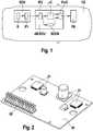
- Fig. 1shows a block diagram of the control device according to the invention with connected components in the vehicle FZ.
- a sensor control unit DCUConnected to the control unit AB-ECU according to the invention is a sensor control unit DCU which has a sensor system S, for example a rotation rate and / or rotational motion sensor, which transmits its data to the airbag control unit AB-ECU via a first interface IF1.
- the interfacecan be a Bus interface or a point-to-point connection.
- the datais received in the airbag control unit AB-ECU from a second interface IF2 and converted into a controller of the internal format, for example SPI (Serial Peripheral Interface).
- SPISerial Peripheral Interface
- the sensor databoth the evaluation circuit namely a microcontroller ⁇ C and a so-called safety controller SCON supplied, so that there are two independent Ausretepfade for the evaluation of the sensor data.
- the control circuit FLICOnly when both evaluations show that the personal protection means PS are to be controlled like airbags does the control circuit FLIC, which receives the evaluation results or activation signals of the microcontroller ⁇ C or the safety controller SCON, control the personal protection means.
- ignition elementsare subjected to an ignition current.
- This functional basic structurecan be varied, for example, sensors can also be arranged in the airbag control unit ABECU. Additional data from other control units, for example via a CAN transceiver, can be taken into account in the evaluation.
- the signalfor example an acceleration signal
- the safety controller SCONis usually simpler than the microntroler ⁇ C.
- precisely such complex structures as safety controllers such as microcontrollersare also possible.
- the safety controllertherefore usually has threshold value evaluations, which usually have fixed threshold values, and therefore these evaluations are not as accurate as those of a more complex software program.
- the control circuit FLIChas corresponding evaluation electronics in order to be able to evaluate the control signals of the microcontroller ⁇ C and the safety controller SCON.
- evaluation electronicsin order to be able to evaluate the control signals of the microcontroller ⁇ C and the safety controller SCON.
- the control unit ABECUstill further components are necessary.
- the airbag control unitis usually installed in the area of the vehicle tunnel. However, if it has no sensors, it is possible to install it in other places. It is only necessary to ensure that in the case of an accident, this airbag control unit is destroyed at most in a late phase of the accident.
- Fig. 2shows a view of a circuit board 20, as it can be used according to the invention.
- the printed circuit board 20,which is configured in particular for SMD components and therefore has only holes for the attachment of the printed circuit board or fixing to the plastic floor or in conjunction with the plastic cover takes various electrical components 21 and the pin header 22, the connection with the Interface in the plastic lid manufactures.
- the components 21 and the pin header 22are fixed, for example, by a so-called reflow process on the circuit board and thus soldered.
- the header 22is presently formed in SMD technology. Ie. It can be designed to save space without a large plastic body.
- the pin headercan be implemented by means of through-hole soldering technology, THRS (Through Hole Reflow Soldering) or press-fit technology.
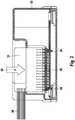
- Fig. 3shows a side sectional view of the control device according to the invention with its housing 32 and the mating connector 31 which connects the wiring harness 36 with the interface on the circuit board through the opening in the plastic cover.
- the plugging direction and the direction of the powerare directed perpendicularly to the circuit board, as shown in case 30.
- the pin header 35 as the interfacehas plastic pins 34 which are provided for intercepting the forces of the mating connector. Alone the possibility of the plug-in direction not horizontally, but as in the present case to make vertical, leads to significant cost savings.
- Fig. 4shows a further side sectional view of the control device according to the invention.
- the housingBy integrating the pin header in the housing, ie the interface is in the housing and the vertical mating of the mating connector there is a danger of the ingress of dripping water into the control unit.
- the housingwas designed with a step in the area of the pin header. This stage close mating connector and the housing cover flush, so that the penetration of a showerlabels no water can penetrate through the opening into the housing.
- Reference numeral 41denotes the shower label and reference numeral 40 denotes the step in the housing cover.
- Fig. 5shows in a flow chart the flow of a process.
- electrical componentsare arranged on the printed circuit board, for example, by soldering or gluing attached.
- the arrangement of the interfacethat is to say the pin strip, likewise takes place on the printed circuit board by soldering or adhesive bonding.
- step 502an opening through which the mating connector is plugged onto the header is provided in the plastic lid. This can already be provided in the injection molding or another production process for the plastic cover.
- step 503the printed circuit board is arranged between the plastic lid and the plastic floor.
- the attachmentsucceeds, for example, initially via non-positive or positive connection means.
Landscapes
- Engineering & Computer Science (AREA)
- Microelectronics & Electronic Packaging (AREA)
- Mechanical Engineering (AREA)
- Casings For Electric Apparatus (AREA)
- Connector Housings Or Holding Contact Members (AREA)
- Coupling Device And Connection With Printed Circuit (AREA)
- Connection Or Junction Boxes (AREA)
- Details Of Connecting Devices For Male And Female Coupling (AREA)
- Air Bags (AREA)
Description
Translated fromGermanDie Erfindung betrifft ein System aufweisend ein Steuergerät für Personenschutzmittel für ein Fahrzeug und einen Stecker für den Anschluss eines Kabelbaums an das Steuergerät.The invention relates to a system comprising a control device for personal protection means for a vehicle and a plug for connecting a cable harness to the control unit.
Aus der
Aus der
Aus der
Aus der
Aus der
Aus der
Aus
Das erfindungsgemäße System mit den Merkmalen des unabhängigen Patentanspruchs hat dem gegenüber den Vorteil, dass es einfacher und kostengünstiger hergestellt werden kann. Vorteilhafter Weise wird nämlich ein Kunststoffboden verwendet, um die Leiterplatte zu umschließen. Die Schnittstelle wird vorteilhafter Weise auf der Leiterplatte aufgebracht. Diese Schnittstelle ist dann über eine Öffnung im Kunststoffdeckel für eine elektrische Verbindung mit einem Gegenstecker bereit. D. h. elektrische Signale können über die Schnittstelle auf die Leiterplatte und zu den entsprechenden elektrischen Bauelementen gebracht werden und umgekehrt. Die Schnittstelle kann einfacher als gemäß dem Stand der Technik hergestellt werden, da ein separater Kunststoffkörper für die Schnittstelle eingespart wird.The system according to the invention with the features of the independent claim has the advantage that it can be made easier and cheaper. Advantageously, namely a plastic bottom is used to enclose the circuit board. The interface is advantageously applied to the circuit board. This interface is then ready via an opening in the plastic lid for an electrical connection with a mating connector. Ie. electrical signals can be brought via the interface to the circuit board and to the corresponding electrical components and vice versa. The interface can be made simpler than in the prior art, since a separate plastic body is saved for the interface.
Vorliegend ist ein Steuergerät für Personenschutzmittel für ein Fahrzeug ein elektrisches Gerät, das Sensorsignale verarbeitet und in Abhängigkeit davon Steuersignale für die Personenschutzmittel erzeugt. Als Sensorsignale werden beispielsweise Beschleunigigungssignale, Körperschallsignale, Drehbewegungssignale wie Drehratensignale, Luftdrucksignale beispielsweise zur Erkennung eines Seitenaufpralls aber auch Fahrdynamiksignale und andere Startersignale verwendet. Die Personenschutzmittel können dabei beispielsweise Airbags, Gurtstraffer bzw. crashaktive Kopfstützen sein. Diese werden im Falle der Ansteuerung d. h. der Aktivierung mit einem Zündstrom bei pyrotechnischen Zündelementen oder einem Aktivierungsstrom bei elektromagnetischen Aktuatoren aktiviert.In the present case, a control device for personal protection means for a vehicle is an electrical device which processes sensor signals and generates control signals for the personal protection means in dependence thereon. As sensor signals, for example acceleration signals, structure-borne sound signals, rotational motion signals such as yaw rate signals, air pressure signals, for example for detecting a side impact, but also driving dynamics signals and other starter signals are used. The personal protection means may be, for example, airbags, belt tensioners or crash-active headrests. These are in the case of control d. H. activated with an ignition current in pyrotechnic ignition elements or an activation current in electromagnetic actuators.
Bei der Leiterplatte handelt es sich um eine typische Leiterplatte auf die die elektrischen Bauelemente eingesteckt oder aufgeklebt bzw. aufgelötet werden. Insbesondere die sogenannte und bekannte SMD (Surface Mounted Devices-Technik) führt zu einer besonders kostengünstigen Ausführung. Auf der Leiterplatte sind demnach die elektrischen Bauelemente und Verbindungskontakte zwischen diesen Bauelementen vorhanden.The circuit board is a typical circuit board on which the electrical components are plugged or glued or soldered. In particular, the so-called and known SMD (Surface Mounted Devices technology) leads to a particularly cost-effective design. Accordingly, the electrical components and connection contacts between these components are present on the printed circuit board.
Der Kunststoffdeckel und der Kunststoffboden bestehen aus einem Kunststoff, der insbesondere die EMV (Elektromagnetische Verträglichkeit) verbessert. Dabei können beispielsweise folgende Materialien verwendet werden: PBT-GF30 und PA66 GF30, wobei der Glasfaseranteil variabel sein kann. Gegebenenfalls kann eine Beimischung für die Verbesserung von elektrischen Abschirmungseigenschaften vorgesehen sein, also eine bessere elektromagnetische Verträglichkeit.The plastic lid and the plastic bottom are made of a plastic, which improves in particular the EMC (Electromagnetic Compatibility). For example, the following materials can be used: PBT-GF30 and PA66 GF30, whereby the glass fiber content can be variable. Optionally, an admixture for the improvement of electrical shielding properties may be provided, so a better electromagnetic compatibility.
Der Kunststoffdeckel und der Kunststoffboden sind so ausgeführt, dass sie zusammenpassen und dabei die wenigstens eine Leiterplatte mit aufnehmen. In zusammengebautem Zustand ist das Steuergerät tropfwasserfest, sofern der Gegenstecker durch die Öffnung im Kunststoffdeckel auf die Schnittstelle aufgebracht wurde. Die Zusammenbaurichtung ist senkrecht zur Leiterplatte. Die Wasserfestigkeit kann noch durch Dichtungen, die den Gegenstecker im zusammengebauten Zustand umschließen, verbessert werden. Die Dichtungen sind dabei in der Öffnung angebracht.The plastic lid and the plastic bottom are designed so that they fit together while the at least one circuit board with record. When assembled, the control unit is drip-proof, provided that the mating connector has been applied to the interface through the opening in the plastic cover. The assembly direction is perpendicular to the PCB. The water resistance can still through seals that the mating connector in encapsulated state, be improved. The seals are mounted in the opening.
Die wenigstens eine Schnittstelle ist eine Stiftleiste für die Herstellung einer elektrischen Verbindung mit wenigstens einer weiteren Fahrzeugkomponente beispielsweise über einen Kabelbaum.The at least one interface is a pin header for the production of an electrical connection with at least one further vehicle component, for example via a cable harness.
Die Öffnung im Kunststoffdeckel weist eine rechteckige oder andere Form auf, um den Gegenstecker möglichst eng zu umfassen.The opening in the plastic lid has a rectangular or other shape to include the mating connector as closely as possible.
Durch die in den abhängigen Ansprüchen aufgeführten Maßnahmen und Weiterbildungen sind vorteilhafte Verbesserungen des in den unabhängigen Patentansprüchen angegebenen Steuergeräts bzw. Verfahrens möglich.Advantageous improvements of the control device or method specified in the independent patent claims are possible by the measures and developments listed in the dependent claims.
Vorteilhaft ist es, dass die wenigstens eine Schnittstelle die elektrische Verbindung in Zusammenbaurichtung ermöglicht. Diese Zusammenbaurichtung ist senkrecht zur Leiterplatte, d. h. die Zusammenbaurichtung durchstößt die Leiterplatte als Ebene. Damit kann die Schnittstelle einfacher ausgeführt werden, da nicht eine elektrische Verbindung über einen Stecker in der Ebene der Leiterplatte stattfindet, wie es aus dem Stand der Technik bekannt ist. Dies ermöglicht insbesondere die günstigere Herstellung des erfindungsgemäßen Steuergeräts.It is advantageous that the at least one interface enables the electrical connection in the direction of assembly. This assembly direction is perpendicular to the circuit board, d. H. the assembly direction pierces the circuit board as a plane. Thus, the interface can be made simpler, since there is no electrical connection via a plug in the plane of the circuit board, as is known in the art. This allows in particular the cheaper production of the control device according to the invention.
Weiterhin ist der Kunststoffdeckel derart gestaltet, dass ein Stecker, der in die wenigstens eine Schnittstelle eingeführt wird, mit dem Kunststoffdeckel bündig abschließt. Dieser bündiger Abschluss ermöglicht den besseren Einbau des erfindungsgemäßen Steuergeräts im Fahrzeug und ermöglicht auch einen effektiven Schutz gegen Wasser. Bündiger Abschluss bedeutet dabei, dass die Oberfläche des Kunststoffdeckels in der gleichen Ebene ist wie die Oberseite des Steckers der in die Schnittstelle eingeführt wird. Über den Stecker wird nämlich ein Kabelbaum an das Steuergerät angeschlossen. Die Schnittstelle ist im allgemeinen Sprachgebrauch auch als Kundenschnittstelle bekannt. Über diese Schnittstelle werden beispielsweise die Zündmittel angesteuert. Es werden Daten von Sensoren eingelesen und auch Daten von anderen Steuergeräten wie beispielsweise einem Fahrdynamikregelungssteuergerät.Furthermore, the plastic lid is designed such that a plug which is inserted into the at least one interface, flush with the plastic lid. This flush closure allows better installation of the control device according to the invention in the vehicle and also allows effective protection against water. Flush termination means that the surface of the plastic cover is in the same plane as the top of the connector inserted into the interface. Namely, a harness is connected to the controller via the connector. The interface is also commonly known as a customer interface. About this interface, for example, the ignition means driven. Data is read from sensors as well as data from other controllers such as a vehicle dynamics control unit.
Vorzugsweise kann für diesen bündigen Abschluss eine Stufe im Kunststoffdeckel vorgesehen sein, wobei die Stufe im Bereich der Stiftleiste konstruiert ist. Durch diese Stufe schließen Gegenstecker und der Gehäusedeckel bündig ab, so dass durch das Anbringen eines sogenannten Showerlabels kein Wasser über die Öffnung in das Steuergerätegehäuse, das durch den Kunststoffdeckel und den Kunststoffboden gebildet wird, eindringen kann.Preferably, a step in the plastic cover may be provided for this flush termination, wherein the step is constructed in the region of the pin header. By this stage close mating connector and the housing cover flush, so that no water can penetrate through the opening in the control unit housing, which is formed by the plastic lid and the plastic bottom by attaching a so-called Shower Label.
Das Showerlabel kann mittels einer vorgefertigten Klebefolie realisiert werden, wobei die Klebefolie die Aussenkontur des Gehäuses in geeigneter Form aufnimmt und Tropfwasser weder in den Bereich der Steckverbindung noch der Anschraubungen eindringen kann.The shower label can be realized by means of a prefabricated adhesive film, wherein the adhesive film absorbs the outer contour of the housing in a suitable form and dripping water can penetrate neither in the region of the connector nor the screwed connections.
Durch diese Maßnahme wird die Wasserschutzklasse von mindestens IP52 erreicht. Die Gefahr des Eindringens von Tropfwasser in das Steuergerät wird damit vermieden.This measure achieves the water protection class of at least IP52. The risk of the ingress of dripping water into the control unit is thus avoided.
Wie oben bereits angedeutet, ist die Schnittstelle als wenigstens eine Stiftleiste ausgeprägt, wobei der Kunststoffdeckel derart ausgebildet ist, dass die wenigstens eine Öffnung und die wenigstens eine Stiftleiste für eine elektrische Verbindung positioniert werden. Dies kann beispielsweise dadurch erreicht werden, dass der Kunststoffdeckel eine Art Trichter aufweist. Die Fixierung dieser Stiftleiste beispielsweise in SMD-Ausführung erfolgt über diese Art von Trichter im Gehäusedeckel, der die Leiterplatte samt Stecker in die richtige Position bringt. Die Steckung des Gegensteckers mit der Schnittstelle im Kunststoffdeckel erfolgt im Gegensatz zum Stand der Technik senkrecht und nicht waagerecht.As already indicated above, the interface is pronounced as at least one pin strip, wherein the plastic lid is formed such that the at least one opening and the at least one pin header are positioned for an electrical connection. This can be achieved, for example, in that the plastic lid has a kind of funnel. The fixation of this pin header, for example, in SMD design via this type of funnel in the housing cover, which brings the circuit board together with the plug in the correct position. The mating plug with the interface in the plastic lid is done in contrast to the prior art vertically and not horizontally.
Auch weist die Stiftleiste wenigstens zwei Kunststoffpins zum Abfangen von Kräften auf. Diese Kunststoffpins sind beispielsweise in die Leiterplatte eingebracht und führen auch zur Befestigung der Stiftleiste. Die Kräfte sind insbesondere die Kräfte, die beim Anbringen des Gegensteckers in die Schnittstelle im Gehäuse auftreten. Dies führt zu einer erhöhten Zuverlässigkeit des erfindungsgemäßen Steuergeräts.Also, the header has at least two plastic pins for trapping forces. These plastic pins are introduced, for example, in the circuit board and also lead to the attachment of the pin header. The Forces are in particular the forces which occur when the mating connector is fitted in the interface in the housing. This leads to an increased reliability of the control device according to the invention.
Vorteilhafter Weise wird der Gegenstecker mit der wenigstens einen Schnittstelle durch eine Steckkontaktierung verbunden. Dies kann, wie oben angegeben, durch die entsprechende Positionierung begünstigt werden.Advantageously, the mating connector is connected to the at least one interface by a plug-in contact. This can, as stated above, be favored by the corresponding positioning.
Die Stiftleiste kann vorteilhafterweise mit einer Durchstecklöttechnik, einer THRS (Through Hole Reflow Soldering) oder einer Einpresstechnik auf der Leiterplatte befestigt sein.The pin header can advantageously be fastened to the printed circuit board by means of a through-hole soldering technique, a THRS (Through Hole Reflow Soldering) or a press-fit technique.
Ausführungsbeispiele der Erfindung sind in der Zeichnung dargestellt und werden in der nachfolgenden Beschreibung näher erläutert.Embodiments of the invention are illustrated in the drawings and are explained in more detail in the following description.
Es zeigen
- Fig. 1
- ein Blockschaltbild des erfindungsgemäßen Steuergeräts mit angeschlossenen Komponenten im Fahrzeug,
- Fig. 2
- eine schematische Darstellung der Leiterplatte,
- Fig. 3
- eine Seitenschnittansicht des erfindungsgemäßen Steuergeräts,
- Fig. 4
- eine weitere Seitenschnittansicht des erfindungsgemäßen Steuergeräts und
- Fig. 5
- ein Flußdiagramm des erfindungsgemäßen Verfahrens.
- Fig. 1
- a block diagram of the control device according to the invention with connected components in the vehicle,
- Fig. 2
- a schematic representation of the circuit board,
- Fig. 3
- a side sectional view of the control device according to the invention,
- Fig. 4
- a further side sectional view of the control device according to the invention and
- Fig. 5
- a flow chart of the method according to the invention.
Dabei werden beispielsweise Zündelemente mit einem Zündstrom beaufschlagt.In this case, for example, ignition elements are subjected to an ignition current.
Diese funktionelle Grundstruktur kann variiert werden, beispielsweise können Sensoren auch im Airbagsteuergerät ABECU angeordnet sein. Es können noch weitere Daten von anderen Steuergeräten beispielsweise über einen CAN-Transceiver in der Auswertung berücksichtigt werden. Bei den Auswertealgorithmen wird das Signal, beispielsweise ein Beschleunigungssignal üblicher Weise rechentechnisch pragmatisch integriert und mit variablen oder festen Schwellwerten verglichen, um zu einer Ansteuerungsentscheidung zu kommen. Bei einem variablen Schwellwert ist es insbesondere vorteilhaft, den Schwellwert auf das Beschleunigungssignal beispielsweise selbst zu adaptieren. Der Safety Controller SCON ist üblicher Weise einfacher ausgebildet als der Mikrontroler µC. Es sind jedoch auch genau solche komplexen Strukturen als Safety Controller wie ein Mikrocontroller möglich. Üblicher Weise weist der Safety Controller daher Schwellwertauswertungen auf, die üblicher Weise feste Schwellwerte aufweisen und daher sind diese Auswertungen nicht so genau wie die eines komplexeren Softwareprogramms.This functional basic structure can be varied, for example, sensors can also be arranged in the airbag control unit ABECU. Additional data from other control units, for example via a CAN transceiver, can be taken into account in the evaluation. In the evaluation algorithms, the signal, for example an acceleration signal, is usually pragmatically integrated in a computational manner and compared with variable or fixed threshold values in order to arrive at a drive decision. In the case of a variable threshold value, it is particularly advantageous, for example, to adapt the threshold value to the acceleration signal itself. The safety controller SCON is usually simpler than the microntroler μC. However, precisely such complex structures as safety controllers such as microcontrollers are also possible. The safety controller therefore usually has threshold value evaluations, which usually have fixed threshold values, and therefore these evaluations are not as accurate as those of a more complex software program.
Die Ansteuerschaltung FLIC weist entsprechende Auswerteelektronik auf um die Ansteuersignale des Mikrocontrollers µC und des Safety Controllers SCON auswerten zu können. Vorliegend sind nur für das Verständnis der Erfindung notwendigen Bauelemente dargestellt. Für den Betrieb des Steuergeräts ABECU sind noch weitere Bauelemente notwendig.The control circuit FLIC has corresponding evaluation electronics in order to be able to evaluate the control signals of the microcontroller μC and the safety controller SCON. In the present case, only necessary for understanding the invention components are shown. For the operation of the control unit ABECU still further components are necessary.
Das Airbagsteuergerät wird üblicher Weise im Bereich des Fahrzeugtunnels eingebaut. Weist es jedoch keine Sensoren auf, ist es möglich es auch an anderen Orten einzubauen. Dabei ist nur darauf zu achten, dass im Falle eines Unfalls dieses Airbagsteuergerät allenfalls in einer späten Phase des Unfalls zerstört wird.The airbag control unit is usually installed in the area of the vehicle tunnel. However, if it has no sensors, it is possible to install it in other places. It is only necessary to ensure that in the case of an accident, this airbag control unit is destroyed at most in a late phase of the accident.
Die Stiftleiste kann mittels Durchstecklöttechnik, THRS (Through Hole Reflow Soldering) oder Einpresstechnik ausgeführt sein.The pin header can be implemented by means of through-hole soldering technology, THRS (Through Hole Reflow Soldering) or press-fit technology.
In Verfahrensschritt 501 erfolgt die Anordnung der Schnittstelle mithin der Stiftleiste ebenfalls auf der Leiterplatte durch Auflöten oder Aufkleben.In
In Verfahrensschritt 502 wird eine Öffnung, durch die der Gegenstecker auf die Stiftleiste aufgesteckt wird, in dem Kunststoffdeckel vorgesehen. Dies kann im Spritzguß- oder einem anderen Herstellungsverfahren für den Kunststoffdeckel schon so vorgesehen sein.In
In Verfahrensschritt 503 wird die bestückte Leiterplatte zwischen dem Kunststoffdeckel und dem Kunststoffboden angeordnent. Die Befestigung gelingt bspw. zunächst über kraft- oder formschlüssige Verbindungsmittel.In
Claims (5)
- System having a control unit (AB-ECU) for personal protection means (PS) for a vehicle (FZ) and having a plug (31) for the connection of a cable harness to the control unit (AB-ECU), wherein the control unit (AB-ECU) comprises:- at least one printed circuit board (20) for receiving electrical components (21);- a plastic cover (32) and a plastic base between which the at least one printed circuit board (20) is arranged;- at least one interface (22, 35) for an electrical connection to at least one further vehicle component, wherein the at least one interface (22, 35) is provided on the at least one printed circuit board (20) and the plastic cover (32) has at least one opening for establishing the electrical connection, wherein the interface (22, 35) is designed as at least one male strip connector (22, 35), wherein the male strip connector (22, 35) has at least two plastic pins (34) for absorbing forces (F), wherein the plastic cover (32) is designed such that the at least one opening and the at least one male strip connector (22, 35) are positioned for electrical connection, wherein the opening is configured in such a way that the plug (31) is fitted onto the male strip connector (22, 35) for establishing the electrical connection, wherein the insertion direction and the force direction are directed perpendicularly on the printed circuit board (20), wherein the plastic cover (32) is configured in such a way that the plug (31), which is introduced into the at least one opening, terminates flush with the plastic cover (32), so that the surface of the plastic cover (32) is in the same plane as the top side of the plug (31).
- System according to Claim 1,characterized in that the plastic cover (32) has a step (40), so that the top side of the plug (31) and the top side of the plastic cover (32) lie in one plane when the plug (31) is introduced into the at least one opening.
- System according to Claim 1,characterized in that the plastic cover (32) is designed as a funnel.
- System according to Claim 1 or 3,characterized in that the male strip connector (22, 35) is fastened by means of through-hole soldering technology, through-hole reflow soldering or press-fitting technology.
- System according to one of Claims 1, 3 and 4,characterized in that protection against the ingress of water into the housing is realized by means of a prefabricated adhesive film (41), wherein the adhesive film (41) adopts the outer contour of the housing which is formed from the plastic cover (32) and the plastic base.
Applications Claiming Priority (2)
| Application Number | Priority Date | Filing Date | Title |
|---|---|---|---|
| DE102008040157ADE102008040157A1 (en) | 2008-07-03 | 2008-07-03 | Personal protective device for a vehicle or method for assembling such a control device |
| PCT/EP2009/055361WO2010000524A1 (en) | 2008-07-03 | 2009-05-04 | Control unit for personal protection means for a vehicle and method for assembling such a control unit |
Publications (2)
| Publication Number | Publication Date |
|---|---|
| EP2298049A1 EP2298049A1 (en) | 2011-03-23 |
| EP2298049B1true EP2298049B1 (en) | 2019-07-10 |
Family
ID=40942340
Family Applications (1)
| Application Number | Title | Priority Date | Filing Date |
|---|---|---|---|
| EP09772224.3AActiveEP2298049B1 (en) | 2008-07-03 | 2009-05-04 | Control unit for personal protection means for a vehicle |
Country Status (8)
| Country | Link |
|---|---|
| US (1) | US8693205B2 (en) |
| EP (1) | EP2298049B1 (en) |
| KR (1) | KR101565189B1 (en) |
| CN (2) | CN105966338B (en) |
| BR (1) | BRPI0914937A2 (en) |
| DE (1) | DE102008040157A1 (en) |
| RU (1) | RU2538905C2 (en) |
| WO (1) | WO2010000524A1 (en) |
Families Citing this family (12)
| Publication number | Priority date | Publication date | Assignee | Title |
|---|---|---|---|---|
| DE102009054234A1 (en)* | 2009-11-21 | 2011-05-26 | Bayerische Motoren Werke Aktiengesellschaft | Electrical controller for vehicle i.e. motor vehicle, has multi-pin plug connector moved into interior of housing such that counter plug connector does not project beyond contour-installation space of housing in inserted state |
| US8926693B2 (en) | 2010-02-17 | 2015-01-06 | Medtronic, Inc. | Heart valve delivery catheter with safety button |
| JP6084010B2 (en)* | 2011-11-25 | 2017-02-22 | キヤノン株式会社 | Imaging device having a configuration capable of preventing disconnection of connector |
| JP5259858B1 (en)* | 2012-05-16 | 2013-08-07 | 株式会社東芝 | Connectors, circuit modules and electronic equipment |
| DE102012221603A1 (en)* | 2012-11-27 | 2014-06-12 | Robert Bosch Gmbh | Actuator arrangement for window lifter drive in motor car, has electronic component, connector and contact element that are formed by surface mount device technique, and are arranged on circuit board |
| DE102014205744B4 (en)* | 2014-01-24 | 2019-05-29 | Eberspächer Climate Control Systems GmbH & Co. KG | Control unit for a vehicle heater |
| RU2633825C1 (en)* | 2016-07-19 | 2017-10-18 | Александр Валерьевич Погудин | Method of increasing active and passive safety of special vehicles for civilian purpose |
| RU2627905C1 (en)* | 2016-07-25 | 2017-08-14 | Александр Валерьевич Погудин | Method of increasing active and passive safety of mechanical vehicles of civilian purpose, having at least four wheels and used for cargo transportation |
| JP6380574B2 (en)* | 2017-02-22 | 2018-08-29 | マツダ株式会社 | Arrangement structure of auxiliary equipment for vehicle |
| CN108327697A (en)* | 2018-03-14 | 2018-07-27 | 瑞立集团瑞安汽车零部件有限公司 | A kind of integrated form EBS rear axle brake apparatus |
| DE102019113068A1 (en)* | 2019-05-17 | 2020-11-19 | Marelli Automotive Lighting Reutlingen (Germany) GmbH | Circuit board with a plug connection |
| KR102781090B1 (en)* | 2020-02-10 | 2025-03-12 | 현대모비스 주식회사 | Air bag control unit for vehicle |
Citations (5)
| Publication number | Priority date | Publication date | Assignee | Title |
|---|---|---|---|---|
| US5428535A (en)* | 1992-09-17 | 1995-06-27 | Kansei Corporation | Vehicle control unit structure |
| FR2721161A1 (en)* | 1994-06-13 | 1995-12-15 | Valeo Electronique | Motor vehicle electronic module on isolated metal substrate carrying surface mounted components |
| US20010027038A1 (en)* | 2000-01-24 | 2001-10-04 | Hisashi Nishikawa | Electronic device with connector and method of manufacturing the same |
| EP1282345A2 (en)* | 2001-07-31 | 2003-02-05 | TRW Automotive Electronics & Components GmbH & Co. KG | Housing for board with electronic components in vehicle |
| DE10300767A1 (en)* | 2003-01-11 | 2004-09-09 | Hella Kg Hueck & Co. | Electronic device, especially controller, has housing and first and/or second connection unit designed so forces acting on first and/or second connection unit are transferred directly to housing |
Family Cites Families (18)
| Publication number | Priority date | Publication date | Assignee | Title |
|---|---|---|---|---|
| US4637943A (en) | 1984-09-17 | 1987-01-20 | Simmonds Precision | Sealed split instrument housing with foil-backed acrylic transfer adhesive tearband |
| JPS6261856A (en)* | 1985-09-12 | 1987-03-18 | Yazaki Corp | Wiring device assembled with functions for automobile |
| DE3933084A1 (en)* | 1989-10-04 | 1991-04-11 | Bosch Gmbh Robert | HOUSING FOR AN ELECTRONIC CIRCUIT |
| WO1995000363A1 (en)* | 1993-06-26 | 1995-01-05 | Robert Bosch Gmbh | Built-on control device |
| DE9315970U1 (en) | 1993-10-20 | 1993-12-02 | Mannesmann Kienzle Gmbh, 78052 Villingen-Schwenningen | Arrangement for closing an opening in a housing |
| DE4426465A1 (en)* | 1994-07-26 | 1996-02-01 | Siemens Ag | Connection part between electrical connections inside a housing and connections protruding from the housing |
| JPH08337083A (en)* | 1995-06-13 | 1996-12-24 | Mitsubishi Electric Corp | IC card |
| CA2195830C (en)* | 1996-01-31 | 2000-05-16 | Kouichi Uezono | Connector fixing construction |
| DE59701895D1 (en) | 1996-09-19 | 2000-07-20 | Siemens Ag | AIRBAG CONTROL UNIT |
| DE19704152C2 (en)* | 1997-02-04 | 1998-11-05 | Siemens Ag | Control device for an anti-lock braking system |
| DE19722357C1 (en)* | 1997-05-28 | 1998-11-19 | Bosch Gmbh Robert | Control unit |
| JP3673422B2 (en)* | 1999-03-12 | 2005-07-20 | 株式会社オートネットワーク技術研究所 | Branch connection box |
| AUPQ729400A0 (en)* | 2000-05-04 | 2000-05-25 | Robert Bosch Gmbh | An electronic control module for a vehicle |
| DE20012623U1 (en) | 2000-07-18 | 2000-11-30 | TRW Automotive Electronics & Components GmbH & Co. KG, 78315 Radolfzell | Housing for an electronic control unit in vehicles |
| DE10107949B4 (en) | 2001-02-20 | 2005-01-13 | Conti Temic Microelectronic Gmbh | Car tax system |
| RU2297344C2 (en)* | 2002-07-03 | 2007-04-20 | Кунт Электроник Санайи Ве Тижарет Аноним Ширкети | Electronic changeover module |
| RU2268829C2 (en)* | 2004-03-12 | 2006-01-27 | Михаил Викторович Ерещенко | Automobile on-board information system |
| DE102008040156A1 (en)* | 2008-07-03 | 2010-01-07 | Robert Bosch Gmbh | Personal protective device for a vehicle and a method for assembling such a control device |
- 2008
- 2008-07-03DEDE102008040157Apatent/DE102008040157A1/ennot_activeCeased
- 2009
- 2009-05-04CNCN201610317972.2Apatent/CN105966338B/ennot_activeExpired - Fee Related
- 2009-05-04WOPCT/EP2009/055361patent/WO2010000524A1/enactiveApplication Filing
- 2009-05-04RURU2011103236/07Apatent/RU2538905C2/ennot_activeIP Right Cessation
- 2009-05-04EPEP09772224.3Apatent/EP2298049B1/enactiveActive
- 2009-05-04KRKR1020107029857Apatent/KR101565189B1/ennot_activeExpired - Fee Related
- 2009-05-04BRBRPI0914937Apatent/BRPI0914937A2/ennot_activeApplication Discontinuation
- 2009-05-04USUS13/002,367patent/US8693205B2/ennot_activeExpired - Fee Related
- 2009-05-04CNCN2009801257195Apatent/CN102084732A/enactivePending
Patent Citations (5)
| Publication number | Priority date | Publication date | Assignee | Title |
|---|---|---|---|---|
| US5428535A (en)* | 1992-09-17 | 1995-06-27 | Kansei Corporation | Vehicle control unit structure |
| FR2721161A1 (en)* | 1994-06-13 | 1995-12-15 | Valeo Electronique | Motor vehicle electronic module on isolated metal substrate carrying surface mounted components |
| US20010027038A1 (en)* | 2000-01-24 | 2001-10-04 | Hisashi Nishikawa | Electronic device with connector and method of manufacturing the same |
| EP1282345A2 (en)* | 2001-07-31 | 2003-02-05 | TRW Automotive Electronics & Components GmbH & Co. KG | Housing for board with electronic components in vehicle |
| DE10300767A1 (en)* | 2003-01-11 | 2004-09-09 | Hella Kg Hueck & Co. | Electronic device, especially controller, has housing and first and/or second connection unit designed so forces acting on first and/or second connection unit are transferred directly to housing |
Also Published As
| Publication number | Publication date |
|---|---|
| CN105966338A (en) | 2016-09-28 |
| KR101565189B1 (en) | 2015-11-02 |
| US20110182043A1 (en) | 2011-07-28 |
| US8693205B2 (en) | 2014-04-08 |
| DE102008040157A1 (en) | 2010-01-07 |
| WO2010000524A1 (en) | 2010-01-07 |
| EP2298049A1 (en) | 2011-03-23 |
| RU2538905C2 (en) | 2015-01-10 |
| BRPI0914937A2 (en) | 2015-10-20 |
| CN105966338B (en) | 2019-10-11 |
| KR20110050597A (en) | 2011-05-16 |
| CN102084732A (en) | 2011-06-01 |
| RU2011103236A (en) | 2012-08-10 |
Similar Documents
| Publication | Publication Date | Title |
|---|---|---|
| EP2298049B1 (en) | Control unit for personal protection means for a vehicle | |
| EP2282914B1 (en) | Control device for passenger protection means for a vehicle and method for assembling a control device for passenger protection means for a vehicle | |
| DE19936300B4 (en) | Pressure detection device and pressure detection device arrangement hereby | |
| EP2296942B1 (en) | Control unit for personal protection means for a vehicle and a method for assembling such a control unit | |
| EP0977979B1 (en) | Method for producing a sensor module, and corresponding sensor module | |
| EP1776565B1 (en) | Sensor for motor vehicles | |
| EP2816372A2 (en) | Distance sensor for a motor vehicle, and assembly of a plurality of distance sensors | |
| DE19755767A1 (en) | Housing for automobile electronic control device | |
| EP1095822B1 (en) | Air bag control unit | |
| WO2011045228A2 (en) | Adapter plate for fixing a housing in a vehicle and corresponding control device | |
| WO2011079896A1 (en) | Sensor with a housing, and method for the production thereof | |
| DE102006032998A1 (en) | Sensor module has sensor strip comprises multiple individual cables and casing, where sending and receiving unit is arranged in housing, and sensor strip is attached to sending and receiving unit for transmission of signals | |
| DE102004033559A1 (en) | Sealing a control unit | |
| EP2219425B1 (en) | Circuit module, in particular control module for a driving dynamics regulating system | |
| DE102012218929A1 (en) | sensor device | |
| DE102008009947A1 (en) | Device for receiving an electrical / electronic component and corresponding mounting method and cover for such a device | |
| DE10239601B4 (en) | On a holding part mounted electronic impact sensor | |
| DE102015206616A1 (en) | Printed circuit board for electronic function control for a vehicle | |
| DE10205818B4 (en) | Housing for an electrical device | |
| WO2018068921A1 (en) | Sensor device for a vehicle, motor vehicle | |
| WO2018046176A1 (en) | Door handle of a vehicle | |
| WO2015110372A1 (en) | Programming a programmable component received in a housing | |
| DE102005042248B3 (en) | Method for forming molded part e.g., for motor vehicle, has electric contact element provided in pluggable connector with conductor element and flat conductor | |
| EP1622438A2 (en) | Electronic apparatus, particularly vehicle sensor | |
| WO2013010836A2 (en) | Connector module, in particular for window lifter drives, and method for producing said module |
Legal Events
| Date | Code | Title | Description |
|---|---|---|---|
| PUAI | Public reference made under article 153(3) epc to a published international application that has entered the european phase | Free format text:ORIGINAL CODE: 0009012 | |
| 17P | Request for examination filed | Effective date:20110203 | |
| AK | Designated contracting states | Kind code of ref document:A1 Designated state(s):AT BE BG CH CY CZ DE DK EE ES FI FR GB GR HR HU IE IS IT LI LT LU LV MC MK MT NL NO PL PT RO SE SI SK TR | |
| AX | Request for extension of the european patent | Extension state:AL BA RS | |
| DAX | Request for extension of the european patent (deleted) | ||
| 17Q | First examination report despatched | Effective date:20131002 | |
| STAA | Information on the status of an ep patent application or granted ep patent | Free format text:STATUS: EXAMINATION IS IN PROGRESS | |
| GRAP | Despatch of communication of intention to grant a patent | Free format text:ORIGINAL CODE: EPIDOSNIGR1 | |
| STAA | Information on the status of an ep patent application or granted ep patent | Free format text:STATUS: GRANT OF PATENT IS INTENDED | |
| INTG | Intention to grant announced | Effective date:20181128 | |
| GRAS | Grant fee paid | Free format text:ORIGINAL CODE: EPIDOSNIGR3 | |
| GRAA | (expected) grant | Free format text:ORIGINAL CODE: 0009210 | |
| STAA | Information on the status of an ep patent application or granted ep patent | Free format text:STATUS: THE PATENT HAS BEEN GRANTED | |
| AK | Designated contracting states | Kind code of ref document:B1 Designated state(s):AT BE BG CH CY CZ DE DK EE ES FI FR GB GR HR HU IE IS IT LI LT LU LV MC MK MT NL NO PL PT RO SE SI SK TR | |
| REG | Reference to a national code | Ref country code:GB Ref legal event code:FG4D Free format text:NOT ENGLISH | |
| REG | Reference to a national code | Ref country code:CH Ref legal event code:EP Ref country code:AT Ref legal event code:REF Ref document number:1154950 Country of ref document:AT Kind code of ref document:T Effective date:20190715 | |
| REG | Reference to a national code | Ref country code:DE Ref legal event code:R096 Ref document number:502009015871 Country of ref document:DE | |
| REG | Reference to a national code | Ref country code:IE Ref legal event code:FG4D Free format text:LANGUAGE OF EP DOCUMENT: GERMAN | |
| REG | Reference to a national code | Ref country code:NL Ref legal event code:MP Effective date:20190710 | |
| REG | Reference to a national code | Ref country code:LT Ref legal event code:MG4D | |
| PG25 | Lapsed in a contracting state [announced via postgrant information from national office to epo] | Ref country code:BG Free format text:LAPSE BECAUSE OF FAILURE TO SUBMIT A TRANSLATION OF THE DESCRIPTION OR TO PAY THE FEE WITHIN THE PRESCRIBED TIME-LIMIT Effective date:20191010 Ref country code:SE Free format text:LAPSE BECAUSE OF FAILURE TO SUBMIT A TRANSLATION OF THE DESCRIPTION OR TO PAY THE FEE WITHIN THE PRESCRIBED TIME-LIMIT Effective date:20190710 Ref country code:HR Free format text:LAPSE BECAUSE OF FAILURE TO SUBMIT A TRANSLATION OF THE DESCRIPTION OR TO PAY THE FEE WITHIN THE PRESCRIBED TIME-LIMIT Effective date:20190710 Ref country code:LT Free format text:LAPSE BECAUSE OF FAILURE TO SUBMIT A TRANSLATION OF THE DESCRIPTION OR TO PAY THE FEE WITHIN THE PRESCRIBED TIME-LIMIT Effective date:20190710 Ref country code:FI Free format text:LAPSE BECAUSE OF FAILURE TO SUBMIT A TRANSLATION OF THE DESCRIPTION OR TO PAY THE FEE WITHIN THE PRESCRIBED TIME-LIMIT Effective date:20190710 Ref country code:PT Free format text:LAPSE BECAUSE OF FAILURE TO SUBMIT A TRANSLATION OF THE DESCRIPTION OR TO PAY THE FEE WITHIN THE PRESCRIBED TIME-LIMIT Effective date:20191111 Ref country code:NL Free format text:LAPSE BECAUSE OF FAILURE TO SUBMIT A TRANSLATION OF THE DESCRIPTION OR TO PAY THE FEE WITHIN THE PRESCRIBED TIME-LIMIT Effective date:20190710 Ref country code:NO Free format text:LAPSE BECAUSE OF FAILURE TO SUBMIT A TRANSLATION OF THE DESCRIPTION OR TO PAY THE FEE WITHIN THE PRESCRIBED TIME-LIMIT Effective date:20191010 | |
| PG25 | Lapsed in a contracting state [announced via postgrant information from national office to epo] | Ref country code:ES Free format text:LAPSE BECAUSE OF FAILURE TO SUBMIT A TRANSLATION OF THE DESCRIPTION OR TO PAY THE FEE WITHIN THE PRESCRIBED TIME-LIMIT Effective date:20190710 Ref country code:IS Free format text:LAPSE BECAUSE OF FAILURE TO SUBMIT A TRANSLATION OF THE DESCRIPTION OR TO PAY THE FEE WITHIN THE PRESCRIBED TIME-LIMIT Effective date:20191110 Ref country code:LV Free format text:LAPSE BECAUSE OF FAILURE TO SUBMIT A TRANSLATION OF THE DESCRIPTION OR TO PAY THE FEE WITHIN THE PRESCRIBED TIME-LIMIT Effective date:20190710 Ref country code:GR Free format text:LAPSE BECAUSE OF FAILURE TO SUBMIT A TRANSLATION OF THE DESCRIPTION OR TO PAY THE FEE WITHIN THE PRESCRIBED TIME-LIMIT Effective date:20191011 | |
| PG25 | Lapsed in a contracting state [announced via postgrant information from national office to epo] | Ref country code:TR Free format text:LAPSE BECAUSE OF FAILURE TO SUBMIT A TRANSLATION OF THE DESCRIPTION OR TO PAY THE FEE WITHIN THE PRESCRIBED TIME-LIMIT Effective date:20190710 | |
| RAP2 | Party data changed (patent owner data changed or rights of a patent transferred) | Owner name:ROBERT BOSCH GMBH | |
| PG25 | Lapsed in a contracting state [announced via postgrant information from national office to epo] | Ref country code:IT Free format text:LAPSE BECAUSE OF FAILURE TO SUBMIT A TRANSLATION OF THE DESCRIPTION OR TO PAY THE FEE WITHIN THE PRESCRIBED TIME-LIMIT Effective date:20190710 Ref country code:RO Free format text:LAPSE BECAUSE OF FAILURE TO SUBMIT A TRANSLATION OF THE DESCRIPTION OR TO PAY THE FEE WITHIN THE PRESCRIBED TIME-LIMIT Effective date:20190710 Ref country code:PL Free format text:LAPSE BECAUSE OF FAILURE TO SUBMIT A TRANSLATION OF THE DESCRIPTION OR TO PAY THE FEE WITHIN THE PRESCRIBED TIME-LIMIT Effective date:20190710 Ref country code:EE Free format text:LAPSE BECAUSE OF FAILURE TO SUBMIT A TRANSLATION OF THE DESCRIPTION OR TO PAY THE FEE WITHIN THE PRESCRIBED TIME-LIMIT Effective date:20190710 Ref country code:DK Free format text:LAPSE BECAUSE OF FAILURE TO SUBMIT A TRANSLATION OF THE DESCRIPTION OR TO PAY THE FEE WITHIN THE PRESCRIBED TIME-LIMIT Effective date:20190710 | |
| PG25 | Lapsed in a contracting state [announced via postgrant information from national office to epo] | Ref country code:SK Free format text:LAPSE BECAUSE OF FAILURE TO SUBMIT A TRANSLATION OF THE DESCRIPTION OR TO PAY THE FEE WITHIN THE PRESCRIBED TIME-LIMIT Effective date:20190710 Ref country code:IS Free format text:LAPSE BECAUSE OF FAILURE TO SUBMIT A TRANSLATION OF THE DESCRIPTION OR TO PAY THE FEE WITHIN THE PRESCRIBED TIME-LIMIT Effective date:20200224 Ref country code:CZ Free format text:LAPSE BECAUSE OF FAILURE TO SUBMIT A TRANSLATION OF THE DESCRIPTION OR TO PAY THE FEE WITHIN THE PRESCRIBED TIME-LIMIT Effective date:20190710 | |
| REG | Reference to a national code | Ref country code:DE Ref legal event code:R097 Ref document number:502009015871 Country of ref document:DE | |
| PLBE | No opposition filed within time limit | Free format text:ORIGINAL CODE: 0009261 | |
| STAA | Information on the status of an ep patent application or granted ep patent | Free format text:STATUS: NO OPPOSITION FILED WITHIN TIME LIMIT | |
| PG2D | Information on lapse in contracting state deleted | Ref country code:IS | |
| 26N | No opposition filed | Effective date:20200603 | |
| PG25 | Lapsed in a contracting state [announced via postgrant information from national office to epo] | Ref country code:SI Free format text:LAPSE BECAUSE OF FAILURE TO SUBMIT A TRANSLATION OF THE DESCRIPTION OR TO PAY THE FEE WITHIN THE PRESCRIBED TIME-LIMIT Effective date:20190710 | |
| REG | Reference to a national code | Ref country code:DE Ref legal event code:R119 Ref document number:502009015871 Country of ref document:DE | |
| PG25 | Lapsed in a contracting state [announced via postgrant information from national office to epo] | Ref country code:MC Free format text:LAPSE BECAUSE OF FAILURE TO SUBMIT A TRANSLATION OF THE DESCRIPTION OR TO PAY THE FEE WITHIN THE PRESCRIBED TIME-LIMIT Effective date:20190710 Ref country code:LI Free format text:LAPSE BECAUSE OF NON-PAYMENT OF DUE FEES Effective date:20200531 Ref country code:CH Free format text:LAPSE BECAUSE OF NON-PAYMENT OF DUE FEES Effective date:20200531 | |
| REG | Reference to a national code | Ref country code:BE Ref legal event code:MM Effective date:20200531 | |
| GBPC | Gb: european patent ceased through non-payment of renewal fee | Effective date:20200504 | |
| PG25 | Lapsed in a contracting state [announced via postgrant information from national office to epo] | Ref country code:LU Free format text:LAPSE BECAUSE OF NON-PAYMENT OF DUE FEES Effective date:20200504 | |
| PG25 | Lapsed in a contracting state [announced via postgrant information from national office to epo] | Ref country code:IE Free format text:LAPSE BECAUSE OF NON-PAYMENT OF DUE FEES Effective date:20200504 Ref country code:GB Free format text:LAPSE BECAUSE OF NON-PAYMENT OF DUE FEES Effective date:20200504 Ref country code:FR Free format text:LAPSE BECAUSE OF NON-PAYMENT OF DUE FEES Effective date:20200531 | |
| PG25 | Lapsed in a contracting state [announced via postgrant information from national office to epo] | Ref country code:BE Free format text:LAPSE BECAUSE OF NON-PAYMENT OF DUE FEES Effective date:20200531 Ref country code:DE Free format text:LAPSE BECAUSE OF NON-PAYMENT OF DUE FEES Effective date:20201201 | |
| REG | Reference to a national code | Ref country code:AT Ref legal event code:MM01 Ref document number:1154950 Country of ref document:AT Kind code of ref document:T Effective date:20200504 | |
| PG25 | Lapsed in a contracting state [announced via postgrant information from national office to epo] | Ref country code:AT Free format text:LAPSE BECAUSE OF NON-PAYMENT OF DUE FEES Effective date:20200504 | |
| PG25 | Lapsed in a contracting state [announced via postgrant information from national office to epo] | Ref country code:MT Free format text:LAPSE BECAUSE OF FAILURE TO SUBMIT A TRANSLATION OF THE DESCRIPTION OR TO PAY THE FEE WITHIN THE PRESCRIBED TIME-LIMIT Effective date:20190710 Ref country code:CY Free format text:LAPSE BECAUSE OF FAILURE TO SUBMIT A TRANSLATION OF THE DESCRIPTION OR TO PAY THE FEE WITHIN THE PRESCRIBED TIME-LIMIT Effective date:20190710 | |
| PG25 | Lapsed in a contracting state [announced via postgrant information from national office to epo] | Ref country code:MK Free format text:LAPSE BECAUSE OF FAILURE TO SUBMIT A TRANSLATION OF THE DESCRIPTION OR TO PAY THE FEE WITHIN THE PRESCRIBED TIME-LIMIT Effective date:20190710 |