EP2296596B1 - Controlling a phacoemulsification system based on real-time analysis of image data - Google Patents
Controlling a phacoemulsification system based on real-time analysis of image dataDownload PDFInfo
- Publication number
- EP2296596B1 EP2296596B1EP09763334.1AEP09763334AEP2296596B1EP 2296596 B1EP2296596 B1EP 2296596B1EP 09763334 AEP09763334 AEP 09763334AEP 2296596 B1EP2296596 B1EP 2296596B1
- Authority
- EP
- European Patent Office
- Prior art keywords
- surgical
- instrument
- events
- detected
- data
- Prior art date
- Legal status (The legal status is an assumption and is not a legal conclusion. Google has not performed a legal analysis and makes no representation as to the accuracy of the status listed.)
- Not-in-force
Links
- 238000010223real-time analysisMethods0.000titledescription2
- 238000000034methodMethods0.000claimsdescription53
- 238000001356surgical procedureMethods0.000claimsdescription44
- 230000004044responseEffects0.000claimsdescription34
- 238000010191image analysisMethods0.000claimsdescription24
- 238000012544monitoring processMethods0.000claimsdescription16
- 238000012545processingMethods0.000claimsdescription16
- 230000009118appropriate responseEffects0.000claimsdescription13
- 230000008569processEffects0.000claimsdescription5
- 230000002123temporal effectEffects0.000claimsdescription4
- 238000013461designMethods0.000description37
- 238000003384imaging methodMethods0.000description15
- 238000004458analytical methodMethods0.000description13
- 238000010586diagramMethods0.000description12
- 230000003287optical effectEffects0.000description11
- 238000003909pattern recognitionMethods0.000description10
- 238000004891communicationMethods0.000description8
- 230000001276controlling effectEffects0.000description7
- 238000003708edge detectionMethods0.000description7
- 208000002177CataractDiseases0.000description6
- 230000007613environmental effectEffects0.000description6
- 238000003860storageMethods0.000description5
- 210000000577adipose tissueAnatomy0.000description4
- 230000008859changeEffects0.000description4
- 238000001514detection methodMethods0.000description4
- 239000012530fluidSubstances0.000description4
- 230000002596correlated effectEffects0.000description3
- 230000002262irrigationEffects0.000description3
- 238000003973irrigationMethods0.000description3
- 231100000430skin reactionToxicity0.000description3
- 230000008901benefitEffects0.000description2
- 230000000875corresponding effectEffects0.000description2
- 238000007405data analysisMethods0.000description2
- 238000009826distributionMethods0.000description2
- 230000006870functionEffects0.000description2
- 238000003825pressingMethods0.000description2
- 230000005855radiationEffects0.000description2
- 238000009877renderingMethods0.000description2
- 238000001228spectrumMethods0.000description2
- 230000001360synchronised effectEffects0.000description2
- 210000001519tissueAnatomy0.000description2
- 230000000007visual effectEffects0.000description2
- 230000004075alterationEffects0.000description1
- 230000036772blood pressureEffects0.000description1
- 238000009529body temperature measurementMethods0.000description1
- 239000013078crystalSubstances0.000description1
- 230000001186cumulative effectEffects0.000description1
- 238000005520cutting processMethods0.000description1
- 238000013500data storageMethods0.000description1
- 230000001419dependent effectEffects0.000description1
- 230000000694effectsEffects0.000description1
- 238000005516engineering processMethods0.000description1
- 230000002708enhancing effectEffects0.000description1
- 230000001678irradiating effectEffects0.000description1
- 230000004130lipolysisEffects0.000description1
- 230000002934lysing effectEffects0.000description1
- 238000005259measurementMethods0.000description1
- 230000007246mechanismEffects0.000description1
- 230000004048modificationEffects0.000description1
- 238000012986modificationMethods0.000description1
- 230000037361pathwayEffects0.000description1
- 230000008447perceptionEffects0.000description1
- 230000002572peristaltic effectEffects0.000description1
- 238000007670refiningMethods0.000description1
- 238000001931thermographyMethods0.000description1
- 238000012546transferMethods0.000description1
- 238000013519translationMethods0.000description1
Images


Classifications
- A—HUMAN NECESSITIES
- A61—MEDICAL OR VETERINARY SCIENCE; HYGIENE
- A61F—FILTERS IMPLANTABLE INTO BLOOD VESSELS; PROSTHESES; DEVICES PROVIDING PATENCY TO, OR PREVENTING COLLAPSING OF, TUBULAR STRUCTURES OF THE BODY, e.g. STENTS; ORTHOPAEDIC, NURSING OR CONTRACEPTIVE DEVICES; FOMENTATION; TREATMENT OR PROTECTION OF EYES OR EARS; BANDAGES, DRESSINGS OR ABSORBENT PADS; FIRST-AID KITS
- A61F9/00—Methods or devices for treatment of the eyes; Devices for putting in contact-lenses; Devices to correct squinting; Apparatus to guide the blind; Protective devices for the eyes, carried on the body or in the hand
- A61F9/007—Methods or devices for eye surgery
- A61F9/00736—Instruments for removal of intra-ocular material or intra-ocular injection, e.g. cataract instruments
- A61F9/00745—Instruments for removal of intra-ocular material or intra-ocular injection, e.g. cataract instruments using mechanical vibrations, e.g. ultrasonic
- A—HUMAN NECESSITIES
- A61—MEDICAL OR VETERINARY SCIENCE; HYGIENE
- A61B—DIAGNOSIS; SURGERY; IDENTIFICATION
- A61B90/00—Instruments, implements or accessories specially adapted for surgery or diagnosis and not covered by any of the groups A61B1/00 - A61B50/00, e.g. for luxation treatment or for protecting wound edges
- A61B90/20—Surgical microscopes characterised by non-optical aspects
- A—HUMAN NECESSITIES
- A61—MEDICAL OR VETERINARY SCIENCE; HYGIENE
- A61B—DIAGNOSIS; SURGERY; IDENTIFICATION
- A61B90/00—Instruments, implements or accessories specially adapted for surgery or diagnosis and not covered by any of the groups A61B1/00 - A61B50/00, e.g. for luxation treatment or for protecting wound edges
- A61B90/36—Image-producing devices or illumination devices not otherwise provided for
- A61B90/361—Image-producing devices, e.g. surgical cameras
- A—HUMAN NECESSITIES
- A61—MEDICAL OR VETERINARY SCIENCE; HYGIENE
- A61B—DIAGNOSIS; SURGERY; IDENTIFICATION
- A61B17/00—Surgical instruments, devices or methods
- A61B17/02—Surgical instruments, devices or methods for holding wounds open, e.g. retractors; Tractors
- A61B17/0231—Surgical instruments, devices or methods for holding wounds open, e.g. retractors; Tractors for eye surgery
- A—HUMAN NECESSITIES
- A61—MEDICAL OR VETERINARY SCIENCE; HYGIENE
- A61B—DIAGNOSIS; SURGERY; IDENTIFICATION
- A61B17/00—Surgical instruments, devices or methods
- A61B2017/00017—Electrical control of surgical instruments
- A61B2017/00022—Sensing or detecting at the treatment site
- A61B2017/00057—Light
- A—HUMAN NECESSITIES
- A61—MEDICAL OR VETERINARY SCIENCE; HYGIENE
- A61B—DIAGNOSIS; SURGERY; IDENTIFICATION
- A61B17/00—Surgical instruments, devices or methods
- A61B2017/00017—Electrical control of surgical instruments
- A61B2017/00115—Electrical control of surgical instruments with audible or visual output
- A—HUMAN NECESSITIES
- A61—MEDICAL OR VETERINARY SCIENCE; HYGIENE
- A61B—DIAGNOSIS; SURGERY; IDENTIFICATION
- A61B34/00—Computer-aided surgery; Manipulators or robots specially adapted for use in surgery
- A61B34/25—User interfaces for surgical systems
- A61B2034/254—User interfaces for surgical systems being adapted depending on the stage of the surgical procedure
- A—HUMAN NECESSITIES
- A61—MEDICAL OR VETERINARY SCIENCE; HYGIENE
- A61B—DIAGNOSIS; SURGERY; IDENTIFICATION
- A61B90/00—Instruments, implements or accessories specially adapted for surgery or diagnosis and not covered by any of the groups A61B1/00 - A61B50/00, e.g. for luxation treatment or for protecting wound edges
- A61B90/36—Image-producing devices or illumination devices not otherwise provided for
- A61B90/361—Image-producing devices, e.g. surgical cameras
- A61B2090/3612—Image-producing devices, e.g. surgical cameras with images taken automatically
- A—HUMAN NECESSITIES
- A61—MEDICAL OR VETERINARY SCIENCE; HYGIENE
- A61B—DIAGNOSIS; SURGERY; IDENTIFICATION
- A61B34/00—Computer-aided surgery; Manipulators or robots specially adapted for use in surgery
- A61B34/10—Computer-aided planning, simulation or modelling of surgical operations
Definitions
- the present inventionrelates to real-time control of a medical instrument system based on detected surgical events.
- Ocular surgerysuch as phacoemulsification surgery
- the surgeonmay rely on a variety of information originating within the surgical theater environment, which may include the surgeon using her auditory, tactile, and visual senses to ascertain cues during the procedure.
- the surgeonmay use these environmental cues to make decisions regarding adjusting and refining the settings and parameters controlling the medical instrument system to best perform the most effective, efficient and safest possible surgical procedure.
- One example of an environmental cueis reporting an audible alarm to inform the surgeon that the instrument logic has detected a parameter, such as flow for example, has reached a value outside of a desired operating range.
- Medical instrument systemsincorporate numerous sensors to detect and collect information from the surgical theater environment sensors and provide this information as input to software programs that monitor the medical instrument system. Together with advancements in sensor technologies, surgical monitoring software programs continue to evolve to take advantage of advanced sensor capabilities.
- One example of the current state of software sensor state of the artis Advanced Medical Optics' "occlusion mode" functionality provided in certain phacoemulsification systems, wherein a control program monitors vacuum sensors and recognizes vacuum levels exceeding a particular value. Once the control program detects that vacuum levels have exceeded the value, the control program adjusts system parameters accordingly.
- the current state of the artalso entails capturing optical images during the surgical procedure and presenting these optical images with the various instrument settings and sensor readings.
- One example of such a designis Advanced Medical Optics' "Surgical Media Center,” aspects of which are reflected in United States Patent Application Serial No. 11/953,229 , "DIGITAL VIDEO CAPTURE SYSTEM AND METHOD WITH CUSTOMIZABLE GRAPHICAL OVERLAY,” inventors Wayne Wong, et al., filed December 10, 2007.
- the Surgical Media Centerprovides simultaneous replay of surgical camera video images synchronized with medical instrument system settings and parameters. Video and system settings information can be communicated to other systems and subsystems.
- Another system related to capturing of optical images, specifically eye positionis reflected in the United States Patent Nos. 7,044,602 to Chernyak , 7,261,415 to Chernyak , and 7,040,759 to Chernyak et al. , each assigned to VISX, Incorporated of Santa Clara, California.
- Phacoemulsification instrument systems manufacturersprovide products that allow the sensors within the systems to detect information from the surgical environment and pass that data to control programs in order to dynamically generate responses and adjust instrument system settings. In conjunction, manufacturers continue to evolve and improve data analysis programs to recognize certain patterns of information reported from digital video camera imaging data. Image analysis techniques may afford the system the ability to perceive small changes or complex patterns otherwise undetected by a surgeon operating a surgical microscope. Important visual information or cues previously unavailable during a surgical procedure can now be employed during the procedure.
- Ocular surgical procedures in particular, including phacoemulsificationinvolve manual procedures selected by the surgeon based on environmental cues originating from instrument sensors. While manual procedures are effective and in wide use, current surgical procedures can be challenging in a surgical environment due to human response time and the ability to perceive very small changes or very complex patterns within environmental cues. It can be difficult for the surgeon to observe available environmental cues, and appropriately respond to these 'events' quickly and accurately by determining and manually implementing new settings and parameters to adjust the surgical instrument. Enhancing a surgeon's ability to perform the surgical procedure is always advantageous.
- US 2004/0152990 A1describes a method and apparatus to operate a surgical instrument in response to a thermal condition being detected that warrants curtailment of further operation.
- command signalsare generated that cause a needle of the surgical instrument to either have its vibrational speed slowed, have its vibrational movement stopped, or have it withdrawn from its relative position.
- the detectionis of infrared radiation wavelengths and is carried out with either a thermal imaging device or a thermal recognition device. A corresponding temperature of the detected infrared radiation wavelengths is compared to a critical temperature to determine whether the thermal condition has been reached.
- US 7,135,016 B1describes an apparatus for ophthalmic surgery comprising a laser source that generates a laser beam; a scanner comprising an input for said laser beam, and an output of a spatially scanned laser beam; controlling circuitry that drives said scanner to remove tissue in a desired pattern on the eye; a microscope for viewing said tissue removal; and a beam combiner comprising a first input for a line of sight of said microscope and second input for said spatially scanned beam.
- US 2008/0058782 A1describes a method and apparatus for fractional treatment of skin by irradiating the skin with electromagnetic energy.
- Sources of the electromagnetic energycan include radio frequency (RF) generators, lasers, and flashlamps.
- the apparatusincludes at least one sensor configured to detect a positional parameter, a skin characteristic, a skin response, or combinations thereof.
- the sensorprovides feedback to a controller.
- the controllercontrols the treatment parameters, including the treatment density. By sensing the positional parameter, skin characteristic and/or skin response to a treatment, the controller automatically adjusts treatment density in real-time in response to the sensed positional parameter, skin characteristic and/or skin response.
- US 2008/0110236 A1describes a method and system for calibrating an analog sensor used in a digital measurement system.
- the designcomprises generating a precise pressure value set at multiple calibration points and supplying said precise pressure value set to an uncalibrated pressure sensor, detecting sensor changes for the uncalibrated pressure sensor based on each precise pressure value generated, polling an actual pressure reading associated with a sensor change for the uncalibrated pressure sensor for each calibration point, and establishing a mathematical relationship between measured value readings and actual pressure for the uncalibrated sensor. Establishing the mathematical relationship converts the uncalibrated sensor to a newly calibrated sensor.
- a known good sensormay be employed to enhance calibration reliability.
- US 2003/0083536 A1describes a methodology and system for lysing adipose tissue including directing ultrasonic energy at a multiplicity of target volumes within the region, which target volumes contain adipose tissue, thereby to selectively lyse the adipose tissue in the target volumes and generally not lyse non-adipose tissue in the target volumes and computerized tracking of the multiplicity of target volumes notwithstanding movement of the body.
- the lipolysis control computercan receive inputs from a video camera and from a temperature measurement unit.
- the present inventionprovides an apparatus configured to control parameters of a surgical instrument employable in an ocular surgical procedure as set out in Claim 1.
- the present inventionalso provides a method for dynamically adjusting parameters applied to an ocular surgical instrument as set out in Claim 8.
- the present inventionfurther provides a method for performing a surgical procedure which comprises controlling a surgical instrument as set out in Claim 14.
- the present designis directed to mechanized control for adjusting surgical instrument settings and/or parameters, e.g. vacuum, aspiration, etc., based on detected surgical events originating within the surgical operating theater environment.
- the present design arrangementmay include an image analysis component configured to recognize and report surgical events determined from the imaging data, such as imaging data received from a camera or via a surgical microscope.
- the arrangementtypically includes an instrument sensor monitoring and analysis component configured to recognize and report surgical events determined from instrument sensor data.
- the arrangementmay include a surgical instrument controller configured to generate and transmit responses instructing the surgical instrument to adjust specific settings and/or parameters and alter the course of the remaining surgery.
- the present designthus provides for dynamic or real-time control of the medical instrument system and/or medical or surgical instrument.
- the present designprovides for real-time control of the medical instrument system, affording alterations to the course of the remaining surgical procedure, realized from real-time analysis of video imaging data.
- Analysis of the imaging datais typically automated or automatic, i.e. requires zero or minimal user interface.
- Analysis of instrument sensor datamay be employed separately or in combination with image data processing to detect surgical events.
- the present designmay include a graphical user interface to further control automated operations and may include configuration and setup functionality.
- the systemcan provide the ability to assign various predetermined settings and parameters in response to specific detected surgical events and show video and instrument sensor data.
- the present designis intended to provide a reliable, noninvasive, and efficient automatic control mechanism for a medical instrument system for use in dynamically controlling the surgical instrument system in real-time.
- One embodiment of the present designis in or with a phacoemulsification surgical system that comprises an independent graphical user interface (GUI) host module, an instrument host module, a GUI device, and a controller module, such as a foot switch, to control the surgical system.
- GUIgraphical user interface
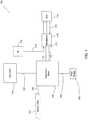
- FIG. 1illustrates an exemplary phacoemulsification/vitrectomy system 100 in a functional block diagram to show the components and interfaces for a safety critical medical instrument system that may be employed in accordance with an aspect of the present invention.
- a serial communication cable 103connects GUI host 101 module and instrument host 102 module for the purposes of controlling the surgical instrument host 102 by the GUI host 101.
- Instrument host 102may be considered a computational device in the arrangement shown, but other arrangements are possible.
- An interface communications cable 120is connected to instrument host 102 module for distributing instrument sensor data 121, and may include distribution of instrument settings and parameters information, to other systems, subsystems and modules within and external to instrument host 102 module. Although shown connected to the instrument host 102 module, interface communications cable 120 may be connected or realized on any other subsystem (not shown) that could accommodate such an interface device able to distribute the respective data.
- a switch module associated with foot pedal 104may transmit control signals relating internal physical and virtual switch position information as input to the instrument host 102 over serial communications cable 105.
- Instrument host 102may provide a database file system for storing configuration parameter values, programs, and other data saved in a storage device (not shown).
- the database file systemmay be realized on the GUI host 101 or any other subsystem (not shown) that could accommodate such a file system.
- the phacoemulsification/vitrectomy system 100has a handpiece 110 that includes a needle and electrical means, typically a piezoelectric crystal, for ultrasonically vibrating the needle.
- the instrument host 102supplies power on line 111 to a phacoemulsification/vitrectomy handpiece 110.
- An irrigation fluid source 112can be fluidly coupled to handpiece 110 through line 113.
- the irrigation fluid and ultrasonic powerare applied by handpiece 110 to a patient's eye, or affected area or region, indicated diagrammatically by block 114.
- the irrigation sourcemay be routed to eye 114 through a separate pathway independent of the handpiece.
- Aspirationis provided to eye 114 by the instrument host 102 pump (not shown), such as a peristaltic pump, through lines 115 and 116.
- a switch 117 disposed on handpiece 110may be utilized to enable a surgeon/operator to select an amplitude of electrical pulses to the handpiece via the instrument host and GUI host. Any suitable input device, such as for example, a foot pedal 104 switch may be utilized in lieu of switch 117.
- the present design surgical systemincludes image processing in or with the phacoemulsification system and may comprise a surgical microscope, digital video cameras, data storage, video rendering, and user interface to control the image capture and analysis system.
- FIG. 2illustrates an exemplary surgical system 200 in a functional block diagram to show the components and interfaces for a real-time digital image capture, distribution, and presentation system that may be employed in accordance with an aspect of the present invention.
- the surgical system digital image processing designwill be discussed herein based on Advanced Medical Optic's surgical media center features and functionality.
- Surgical system 200may include a surgical instrument, for example phacoemulsification instrument 102, such as the phacoemulsification/vitrectomy system 100 shown in FIG. 1 .
- Surgical system 200may further include a surgical microscope 202 focused on the surgical procedure, e.g. patients eye, and may involve digital video cameras 203, or other device suitable for video recording, and may transfer the resulting image data at 204, in analog or digital form, to surgical media center 205 via communications cable 206.
- Surgical media center 205is a processing device that manages the multimedia data recorded by the surgical microscope, and the instrument sensor data 121 in real-time, including but not limited to vacuum, power, flow, and foot pedal position generated from phacoemulsification instrument 102 during the surgical procedure.
- Managing the multimedia dataincludes synchronizing the temporal relationship between the instrument parameters, settings, and sensor data from phaco instrument 102 and the optical data from surgical microscope 202.
- system 200may communicate the digital video as an image data stream, representing the optical data from the procedure/ surgery, with the medical system instrument parameters, settings, and sensor data reported by phaco instrument 102 in real-time to other systems and subsystems.
- the surgical media centermay further include a digital video storage device 207 configured to store the multimedia data recorded.
- Video storage device 207may connect to and be accessed by surgical media center 205 via communications cable 208.
- a video display device 209may connect to surgical media center 205 and digital video storage device 207 via communications cable 208.
- surgical media center 205may record and present a video image of the procedure/ surgery with the medical system instrument parameters and settings utilized by the phacoemulsification instrument 102 in real-time.
- Surgical media center 205may synchronize instrument data with the video stream allowing simultaneous display of video data with a graphical overlay showing the corresponding parameters and system settings at each instant of the procedure on a frame-by-frame basis.
- This cumulative datai.e. the video data synchronized with the setting and parameter data may be stored and archived in digital video storage device 207.
- the usermay select to show or hide different elements of the instrument data rendered on video display device 209.
- the present designtypically includes a real-time surgical instrument control module configured to receive detected surgical events and dynamically adjust instrument parameters and settings to alter the course of the remaining surgery.
- Detected surgical eventsmay originate from image analysis software, instrument sensor monitoring software, and other software components configured to analyze information collected from the surgical environment.
- the detected surgical eventsincluding but not limited to commencements of procedures, termination of procedures, changes in system or patient parameters such as pressure applied, pressure available, patient blood pressure, patient temperature, instrument temperature, and so forth, may be electronically communicated to the instrument control module for matching an appropriate response to received events and sending the response(s) to the surgical instrument.
- the responsemay include commands or instructions containing information relaying adjustments or changes to in-effect instrument settings and parameters.
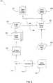
- FIG. 3is a functional block diagram illustrating components and devices for an instrument monitor 301 module with an instrument control module 302 integrated within surgical system 200 for real-time surgical instrument control based on detected surgical events in accordance with an aspect of the present invention.
- a surgical microscopeconfigured to capture an optical image of the eye requiring surgery may communicate the optical images to more than one digital video camera 203.
- digital video cameras 203may convert the optical images received into video images, such as for example a digital image data stream, and provide data streams to one or more image analysis 303 modules.
- Image analysis 303 modulemay analyze the digital image data streams using 'logic' configured to detect imaging specific surgical events 305.
- phaco instrument monitoring 301 modulemay analyze data reported from multiple sensors using 'logic' configured to detect sensor reported specific surgical events 306.
- the present designmay communicate detected surgical events 305 and 306 from the image analysis 303 module and from the phaco instrument monitoring 301 module, respectively, in real-time to phaco instrument control module 302.
- the phaco instrument control module arrangementmay be configured to receive and process data and data analysis information realized from software programs configured to detected surgical events.
- the processing 'logic'may determine from this data appropriate changes to various parameters and settings for phaco instrument 102 such that implementing these changes may alter the course of the remaining surgery.
- the present designmay communicate changes for instrument settings and parameters from phaco instrument control 303 module to phaco instrument 102 for modifying the behavior of the surgical instrument and associated handpiece 114 in real-time.
- settings and parameters available for real-time modificationinclude, but are not limited to controlling: pulse rate and waveform, rate of fluid dispensing, vacuum, aspiration, cutting speed, and combinations thereof.
- a surgeonmay operate surgical microscope 202 to render optical images of the surgical site.
- the surgical microscopemay include one or more digital cameras configured to convert the optical images of the surgical site into a stream of digital image data.
- the digital camera(s)may communicate or deliver the data stream(s) to one or more image analysis 303 modules for processing.
- Data processingmay involve 'logic' configured to detect and report specific surgical events.
- one image analysis software componentmay involve an edge detection capabilities and another image analysis software component may involve pattern recognition techniques.
- the present designmay involve these techniques to provide information from imaging data previously not available to the surgeon.
- the image analysis softwaremay be arranged to accept input from one or more digital cameras. Multiple camera configurations may be positioned to provide for greater depth perception realized by 3D imaging techniques or positioned to provide for multiple viewing angles affording a more complete set of image data. Multiple camera configurations may be arranged to collect non-visible wavelengths such as ultra-violet and infrared and convolve this information with visible wavelength information within the optical images to form a more complete spectrum of light analysis and thus gaining access to new information available for imaging analysis.
- non-visible wavelengthssuch as ultra-violet and infrared
- surgeonmay operate phacoemulsification instrument system 102 to perform activities to complete the procedure.
- the present designmay include one or more software programs arranged to monitor instrument sensors and to control the instrument.
- phaco instrument monitoring 301 modulemay be configured to monitor each sensor incorporated in or with the phaco instrument.
- Phaco instrument control module 302may be configured to provide an appropriate response 304, in real-time, sufficient for dynamically altering the operating settings and parameters of phaco-instrument 102 appropriately when specific surgical events are detected.
- the appropriate responses to a detected surgical eventmay vary depending on the nature and type of event detected.
- Appropriate response 304may include but is not limited to an auditory signal emitted to alert the surgeon, adjusting an operating parameter such as vacuum or fluid flow, and shutdown of the entire system.
- Phaco instrument monitoring 301 modulemay contain logic identifying when specific surgical events occur based upon recognition of predetermined patterns of readings from a sensor or multiple sensors.
- Phaco instrument control module 302may receive continuous and simultaneous communication of surgical events 305 originating from and detected by the image analysis and surgical events 306 originating from and detected by the instrument monitoring module.
- the present designmay be configured to dynamically modify the phaco instrument operating settings and parameters in a predefined manner; affecting a change in the course of the remaining surgery for realizing a safer and more effective ocular procedure.
- the systemmay continuously update settings and operating parameters, in an iterative manner, to remove actively reported events.
- the continuous updatemay involve a feedback arrangement that continuously adjusts the system until the detected event is addressed or the system is shut-down. In this feedback arrangement, the present design may continue to adjust a parameter or other surgical event, reported out of range, until the event is removed by the parameter being restored to an acceptable in range value.
- the present arrangementis configured to correlate surgical events detected by image analysis and instrument monitoring software for determining if they are the same event being detected and reported, or if they are unrelated events.
- the present designmay provide information to the image analysis module for accurate imaging event detection.
- the image analysis component logicmay benefit from knowing the currently selected 'in-use' instrument operating parameters to function correctly.
- the present designs image analysis 303, instrument monitoring 301, and instrument control module 302 softwaremay alternatively comprise one or more distributed software modules or entities and may be realized in hardware, software, firmware, and any combinations thereof to fulfill the functionality the disclosed software programs.
- FIG.4is a functional block diagram illustrating components for an image analysis 303 module for detecting surgical events from digital imaging data in accordance with an aspect of the present invention.
- the present designmay include a pattern recognition 401 component configured to analyze the image data streams for predefined data patterns.
- One potential pattern recognition logic design for extracting desired patterns from image data suitable for use in the current contextis disclosed in "Pattern Recognition Systems and Methods", inventor Shashidhar Sathyanarayana, U.S. Patent Publication 2006/0159319, published July 20, 2006 .
- the present designmay also include an edge detection component 402 configured to analyze the image data streams for detecting edges of one or more objects within the imaging data.
- edge detection logicfor determining the location of at least one edge of an object from image data suitable for use in the current system is disclosed in "System And Method For Edge Detection of an Image", inventor Shashidhar Sathyanarayana, U.S. Patent Publication 2004/0146201, published July 29, 2004 .
- the apparatus and methodmay include an infrared wavelength analysis component 403 for extracting information from the invisible portion of light spectrum.
- a stereoscopic imaging component 404may combine edge detection, pattern recognition, ultra violet and other functionality arranged to analyze multiple data streams rendering stereoscopic content for detecting surgical events realized within multiple views of the surgical procedure.
- image analysis module 303may comprise additional components directed at recovering other types of information from image data 204 for the purpose of generating additional detected events at point 305.
- the edge detection component 402may configure the pattern recognition and edge detection algorithms to identify one or more ocular objects of surgical interest, such as a cataract.
- FIG. 5is a functional block diagram illustrating components for an instrument monitoring module 301 that detects surgical events from instrument sensor data.
- the present designmay include a vacuum sensor analysis component 501 configured to analyze and monitor vacuum related information from sensor data 201.
- Vacuum sensor analysis component 501may monitor sensor data 201 to determine when the actual vacuum pressure reported by the sensor is within a predetermined range of acceptable values associated with the current stage of the ocular procedure. In the situation where the actual value reported exceeds or drops below the expected predetermined range, the present design may generate detected event 306 to indicate such a change has occurred.
- the present designmay include a pressure sensor analysis component 502 configured to analyze and monitor pressure related information from sensor data 201.
- Pressure analysis 502may monitor sensor data 201 for determining if the actual pressure reported by the sensors remains within a predetermined range of values associated with the particular stage of the ocular procedure. In the situation where the actual value reported exceeds or drops below the predetermined range, the present design may generate another detected event 306 to indicate this change in pressure.
- instrument monitoring 301 software modulemay comprise additional components directed at recovering other types of information from sensor data 201 for the purpose of detecting additional events 306.
- FIG. 6is a functional block diagram illustrating components for an instrument control 302 module to assign an appropriate response 304 to detected events 305 and 306.
- the present designmay include an image event response 601 component configured to receive detected events 305 from image analysis module 303 and translate each received event into an appropriate response 304.
- the present designmay include a sensor event response component 602 configured to receive detected events 306 from the instrument monitoring module 301 and translate each received event into an appropriate response 304.
- detected event translationmay involve assigning each event type a response. Each response may be converted or mapped to a predetermined set of software instructions.
- Instrument control module 302may communicate commands at point 604, responsive to each detected event received, to instrument system 100 as an appropriate response 304. The communicated commands and sets of instructions may be received and executed by instrument system 100 for adjusting control of instrument host 102.
- a correlated event response component 603may be provided to receive both image and sensor detected events. Correlated event response 603 may involve comparing the received detected events for determining whether they represent the same or different surgical events. In the situation where the detected image and data event types originate from the same surgical event, the present design may assign a further appropriate response in a manner as previously described for correlated events, or may cancel any duplicate responses originating from and associated with the same surgical event.
- a user interface device executing within surgical system 200may communicate with and enable control of the image analysis, sensor monitoring, and instrument control software for configuration and operational control of the present design's real-time surgical event detection and response automated mode.
- the user interface devicemay include, but is not limited to, a touch screen monitor, mouse, keypad, foot pedal switch, and/or a computer monitor.
- the system 200typically includes algorithms, tables, and data relating desired response to detected surgical event(s). The algorithms and data may be resident within surgical system 200 or realized using external devices and/or software.
- Graphical user interfacesare generally known in the art, and the graphical user interface may provide, for example, touch screen or button to enable/disable automated instrument control and select from a set of operational mode(s) by the user touching the screen or pressing buttons on the interface.
- Other user interfacesmay be provided, such as a selection device including but not limited to a foot pedal switch as discussed.
- the user interface deviceenables the user to select system features, set system parameters, turn functionality on and off, and so forth.
- a graphical user interfacemay be known in the art and can be engaged by touching the screen, pressing buttons, turning dials, and so forth.
- the present designmay adjust instrument settings and parameters based on stored predetermined responses assigned to the particular detected surgical event, either automatically or with user input.
- the image pattern recognition facilitymay detect the presence of a cataract and determine the density of the detected cataract.
- the image pattern recognition facilitymay communicate cataract density information, in real-time, to the instrument control program.
- the instrument control softwaremay assign a tailored set of instructions based on the received cataract density information and communicate the set of instructions for real-time execution by the phacoemulsification instrument affecting control of the surgical procedure in the event of a cataract having the specific density encountered. Real-time altering of instrument settings and parameters in this way may enable the surgeon to continue performing the surgical procedure efficiently, i.e. without interruption to manually adjust the instrument controls.
- the image pattern recognition facility configurationmay detect the presence of a capsular bag and determine the bag's condition, e.g. good, weak, or broken.
- the capsular bag informationmay be communicated from the image pattern recognition facility, in real-time, to the instrument control program.
- the instrument control programmay be configured to assign an immediate phaco "stop-instruction" in the situation when either a weak or broken capsular bag condition is detected.
- the present designmay communicate the "stop-instruction" to the phacoemulsification instrument for real-time execution. Stopping the instrument in this way may prevent surgical complications and enable the surgeon to complete the procedure in a safe manner.
- Further examplesmay include the image analysis software configured to detect a large number of similar surgical events.
- the present designmay allow for assignment of a large number or pattern of similar detected events to a response, such as repeated encounters of excess pressure readings during normal operation, thus affording further refinement in the instruction sets available for controlling the surgical system.
- the present designprovides an ability to control parameters of a surgical instrument employed in a surgical procedure, such as an ocular surgical procedure.
- An image analysis moduledetects surgical events within an image data stream, while an instrument control module receives surgical events detected from the image analysis module and potentially other sources and generates responses to the detected surgical events.
- the instrument control moduleprocesses responses and transmits processed responses in the form of an instruction set.
- the surgical instrumentreceives and executes instruction sets communicated from the instrument control module during the surgical procedure.
- the present designdynamically adjusts parameters applied to a surgical instrument, such as an ocular surgical instrument, detects surgical events from image data collected by a surgical microscope focused on a surgical procedure, establishes a desired response for each detected surgical event, delivers the desired response to the surgical instrument as a set of software instructions, and alters the surgical procedure based on the desired response received as the set of software instructions.
- a surgical instrumentsuch as an ocular surgical instrument
Landscapes
- Health & Medical Sciences (AREA)
- Surgery (AREA)
- Life Sciences & Earth Sciences (AREA)
- Engineering & Computer Science (AREA)
- Veterinary Medicine (AREA)
- Biomedical Technology (AREA)
- Heart & Thoracic Surgery (AREA)
- Nuclear Medicine, Radiotherapy & Molecular Imaging (AREA)
- Animal Behavior & Ethology (AREA)
- General Health & Medical Sciences (AREA)
- Public Health (AREA)
- Ophthalmology & Optometry (AREA)
- Oral & Maxillofacial Surgery (AREA)
- Pathology (AREA)
- Medical Informatics (AREA)
- Molecular Biology (AREA)
- Vascular Medicine (AREA)
- Ultra Sonic Daignosis Equipment (AREA)
- Microscoopes, Condenser (AREA)
Description
- The present invention relates to real-time control of a medical instrument system based on detected surgical events.
- Ocular surgery, such as phacoemulsification surgery, requires a surgeon to continuously make decisions while conducting the surgical procedure. To make these decisions, the surgeon may rely on a variety of information originating within the surgical theater environment, which may include the surgeon using her auditory, tactile, and visual senses to ascertain cues during the procedure. The surgeon may use these environmental cues to make decisions regarding adjusting and refining the settings and parameters controlling the medical instrument system to best perform the most effective, efficient and safest possible surgical procedure. One example of an environmental cue is reporting an audible alarm to inform the surgeon that the instrument logic has detected a parameter, such as flow for example, has reached a value outside of a desired operating range.
- Medical instrument systems incorporate numerous sensors to detect and collect information from the surgical theater environment sensors and provide this information as input to software programs that monitor the medical instrument system. Together with advancements in sensor technologies, surgical monitoring software programs continue to evolve to take advantage of advanced sensor capabilities. One example of the current state of software sensor state of the art is Advanced Medical Optics' "occlusion mode" functionality provided in certain phacoemulsification systems, wherein a control program monitors vacuum sensors and recognizes vacuum levels exceeding a particular value. Once the control program detects that vacuum levels have exceeded the value, the control program adjusts system parameters accordingly.
- The current state of the art also entails capturing optical images during the surgical procedure and presenting these optical images with the various instrument settings and sensor readings. One example of such a design is Advanced Medical Optics' "Surgical Media Center," aspects of which are reflected in United States Patent Application Serial No.
11/953,229 7,044,602 to Chernyak ,7,261,415 to Chernyak , and7,040,759 to Chernyak et al. , each assigned to VISX, Incorporated of Santa Clara, California. - Phacoemulsification instrument systems manufacturers provide products that allow the sensors within the systems to detect information from the surgical environment and pass that data to control programs in order to dynamically generate responses and adjust instrument system settings. In conjunction, manufacturers continue to evolve and improve data analysis programs to recognize certain patterns of information reported from digital video camera imaging data. Image analysis techniques may afford the system the ability to perceive small changes or complex patterns otherwise undetected by a surgeon operating a surgical microscope. Important visual information or cues previously unavailable during a surgical procedure can now be employed during the procedure.
- Ocular surgical procedures in particular, including phacoemulsification, involve manual procedures selected by the surgeon based on environmental cues originating from instrument sensors. While manual procedures are effective and in wide use, current surgical procedures can be challenging in a surgical environment due to human response time and the ability to perceive very small changes or very complex patterns within environmental cues. It can be difficult for the surgeon to observe available environmental cues, and appropriately respond to these 'events' quickly and accurately by determining and manually implementing new settings and parameters to adjust the surgical instrument. Enhancing a surgeon's ability to perform the surgical procedure is always advantageous.
US 2004/0152990 A1 describes a method and apparatus to operate a surgical instrument in response to a thermal condition being detected that warrants curtailment of further operation. When the thermal condition is reached, command signals are generated that cause a needle of the surgical instrument to either have its vibrational speed slowed, have its vibrational movement stopped, or have it withdrawn from its relative position. The detection is of infrared radiation wavelengths and is carried out with either a thermal imaging device or a thermal recognition device. A corresponding temperature of the detected infrared radiation wavelengths is compared to a critical temperature to determine whether the thermal condition has been reached.US 7,135,016 B1 describes an apparatus for ophthalmic surgery comprising a laser source that generates a laser beam; a scanner comprising an input for said laser beam, and an output of a spatially scanned laser beam; controlling circuitry that drives said scanner to remove tissue in a desired pattern on the eye; a microscope for viewing said tissue removal; and a beam combiner comprising a first input for a line of sight of said microscope and second input for said spatially scanned beam.US 2008/0058782 A1 describes a method and apparatus for fractional treatment of skin by irradiating the skin with electromagnetic energy. Sources of the electromagnetic energy can include radio frequency (RF) generators, lasers, and flashlamps. The apparatus includes at least one sensor configured to detect a positional parameter, a skin characteristic, a skin response, or combinations thereof. The sensor provides feedback to a controller. The controller controls the treatment parameters, including the treatment density. By sensing the positional parameter, skin characteristic and/or skin response to a treatment, the controller automatically adjusts treatment density in real-time in response to the sensed positional parameter, skin characteristic and/or skin response.US 2008/0110236 A1 describes a method and system for calibrating an analog sensor used in a digital measurement system. The design comprises generating a precise pressure value set at multiple calibration points and supplying said precise pressure value set to an uncalibrated pressure sensor, detecting sensor changes for the uncalibrated pressure sensor based on each precise pressure value generated, polling an actual pressure reading associated with a sensor change for the uncalibrated pressure sensor for each calibration point, and establishing a mathematical relationship between measured value readings and actual pressure for the uncalibrated sensor. Establishing the mathematical relationship converts the uncalibrated sensor to a newly calibrated sensor. A known good sensor may be employed to enhance calibration reliability.US 2003/0083536 A1 describes a methodology and system for lysing adipose tissue including directing ultrasonic energy at a multiplicity of target volumes within the region, which target volumes contain adipose tissue, thereby to selectively lyse the adipose tissue in the target volumes and generally not lyse non-adipose tissue in the target volumes and computerized tracking of the multiplicity of target volumes notwithstanding movement of the body. The lipolysis control computer can receive inputs from a video camera and from a temperature measurement unit.- Based on the foregoing, it would be advantageous to provide for a system and method that enhances the ability of the system to accurately detect, report, and quickly respond to surgical events from imaging data, and provide information relating environmental changes previously not perceived by the surgeon for use in medical instrument systems that overcomes drawbacks present in previously known designs.
- The present invention provides an apparatus configured to control parameters of a surgical instrument employable in an ocular surgical procedure as set out in Claim 1.
- The present invention also provides a method for dynamically adjusting parameters applied to an ocular surgical instrument as set out in Claim 8.
- The present invention further provides a method for performing a surgical procedure which comprises controlling a surgical instrument as set out in Claim 14.
- Optional features are set out in the dependent claims.
- The present invention is illustrated by way of example, and not by way of limitation, in the figures of the accompanying drawings in which:
FIG. 1 illustrates an exemplary phacoemulsification/vitrectomy system in a functional block diagram to show the components and interfaces for a safety critical medical instrument system that may be employed in accordance with an aspect of the present invention;FIG. 2 illustrates an exemplary surgical system in a functional block diagram to show the components and interfaces for a real-time digital image capture and presentation system that may be employed in accordance with an aspect of the present invention;FIG. 3 is a functional block diagram illustrating components and devices for a phacoemulsification
instrument control module integrated within the surgical system for real-time surgical instrument control based on detected surgical events in accordance with an aspect of the present invention;FIG. 4 is a functional block diagram illustrating components for an image analysis software module for detecting surgical events from digital imaging data in accordance with an aspect of the present invention;FIG. 5 is a functional block diagram illustrating components for an instrument monitoring software module for detecting surgical events from instrument sensor data in accordance with another aspect of the present invention; andFIG. 6 is a functional block diagram illustrating components for an instrument control software module for assigning an appropriate response to detected events in accordance with another aspect of the present invention.- The following description and the drawings illustrate specific embodiments sufficient to enable those skilled in the art to practice the system and method described. Other embodiments may incorporate structural, logical, process and other changes. Examples merely typify possible variations. Individual components and functions are generally optional unless explicitly required, and the sequence of operations may vary. Portions and features of some embodiments may be included in or substituted for those of others.
- The present design is directed to mechanized control for adjusting surgical instrument settings and/or parameters, e.g. vacuum, aspiration, etc., based on detected surgical events originating within the surgical operating theater environment. The present design arrangement may include an image analysis component configured to recognize and report surgical events determined from the imaging data, such as imaging data received from a camera or via a surgical microscope. The arrangement typically includes an instrument sensor monitoring and analysis component configured to recognize and report surgical events determined from instrument sensor data. In addition, the arrangement may include a surgical instrument controller configured to generate and transmit responses instructing the surgical instrument to adjust specific settings and/or parameters and alter the course of the remaining surgery. The present design thus provides for dynamic or real-time control of the medical instrument system and/or medical or surgical instrument.
- In short, the present design provides for real-time control of the medical instrument system, affording alterations to the course of the remaining surgical procedure, realized from real-time analysis of video imaging data. Analysis of the imaging data is typically automated or automatic, i.e. requires zero or minimal user interface. Analysis of instrument sensor data may be employed separately or in combination with image data processing to detect surgical events.
- The present design may include a graphical user interface to further control automated operations and may include configuration and setup functionality. The system can provide the ability to assign various predetermined settings and parameters in response to specific detected surgical events and show video and instrument sensor data.
- The present design is intended to provide a reliable, noninvasive, and efficient automatic control mechanism for a medical instrument system for use in dynamically controlling the surgical instrument system in real-time.
- One embodiment of the present design is in or with a phacoemulsification surgical system that comprises an independent graphical user interface (GUI) host module, an instrument host module, a GUI device, and a controller module, such as a foot switch, to control the surgical system.
FIG. 1 illustrates an exemplary phacoemulsification/vitrectomy system 100 in a functional block diagram to show the components and interfaces for a safety critical medical instrument system that may be employed in accordance with an aspect of the present invention. Aserial communication cable 103 connectsGUI host 101 module andinstrument host 102 module for the purposes of controlling thesurgical instrument host 102 by theGUI host 101.Instrument host 102 may be considered a computational device in the arrangement shown, but other arrangements are possible. Aninterface communications cable 120 is connected toinstrument host 102 module for distributinginstrument sensor data 121, and may include distribution of instrument settings and parameters information, to other systems, subsystems and modules within and external toinstrument host 102 module. Although shown connected to theinstrument host 102 module,interface communications cable 120 may be connected or realized on any other subsystem (not shown) that could accommodate such an interface device able to distribute the respective data.- A switch module associated with
foot pedal 104 may transmit control signals relating internal physical and virtual switch position information as input to theinstrument host 102 overserial communications cable 105.Instrument host 102 may provide a database file system for storing configuration parameter values, programs, and other data saved in a storage device (not shown). In addition, the database file system may be realized on theGUI host 101 or any other subsystem (not shown) that could accommodate such a file system. - The phacoemulsification/
vitrectomy system 100 has ahandpiece 110 that includes a needle and electrical means, typically a piezoelectric crystal, for ultrasonically vibrating the needle. Theinstrument host 102 supplies power online 111 to a phacoemulsification/vitrectomy handpiece 110. Anirrigation fluid source 112 can be fluidly coupled tohandpiece 110 throughline 113. The irrigation fluid and ultrasonic power are applied byhandpiece 110 to a patient's eye, or affected area or region, indicated diagrammatically byblock 114. Alternatively, the irrigation source may be routed to eye 114 through a separate pathway independent of the handpiece. Aspiration is provided to eye 114 by theinstrument host 102 pump (not shown), such as a peristaltic pump, throughlines switch 117 disposed onhandpiece 110 may be utilized to enable a surgeon/operator to select an amplitude of electrical pulses to the handpiece via the instrument host and GUI host. Any suitable input device, such as for example, afoot pedal 104 switch may be utilized in lieu ofswitch 117. - In combination with
phacoemulsification system 100, the present design surgical system includes image processing in or with the phacoemulsification system and may comprise a surgical microscope, digital video cameras, data storage, video rendering, and user interface to control the image capture and analysis system. FIG. 2 illustrates an exemplarysurgical system 200 in a functional block diagram to show the components and interfaces for a real-time digital image capture, distribution, and presentation system that may be employed in accordance with an aspect of the present invention. The surgical system digital image processing design will be discussed herein based on Advanced Medical Optic's surgical media center features and functionality.Surgical system 200 may include a surgical instrument, for example phacoemulsificationinstrument 102, such as the phacoemulsification/vitrectomy system 100 shown inFIG. 1 .Surgical system 200 may further include asurgical microscope 202 focused on the surgical procedure, e.g. patients eye, and may involvedigital video cameras 203, or other device suitable for video recording, and may transfer the resulting image data at 204, in analog or digital form, tosurgical media center 205 viacommunications cable 206.Surgical media center 205 is a processing device that manages the multimedia data recorded by the surgical microscope, and theinstrument sensor data 121 in real-time, including but not limited to vacuum, power, flow, and foot pedal position generated fromphacoemulsification instrument 102 during the surgical procedure. Managing the multimedia data includes synchronizing the temporal relationship between the instrument parameters, settings, and sensor data fromphaco instrument 102 and the optical data fromsurgical microscope 202. In this arrangement,system 200 may communicate the digital video as an image data stream, representing the optical data from the procedure/ surgery, with the medical system instrument parameters, settings, and sensor data reported byphaco instrument 102 in real-time to other systems and subsystems.- The surgical media center may further include a digital
video storage device 207 configured to store the multimedia data recorded.Video storage device 207 may connect to and be accessed bysurgical media center 205 viacommunications cable 208. In addition, avideo display device 209 may connect tosurgical media center 205 and digitalvideo storage device 207 viacommunications cable 208. - In this configuration,
surgical media center 205 may record and present a video image of the procedure/ surgery with the medical system instrument parameters and settings utilized by thephacoemulsification instrument 102 in real-time.Surgical media center 205 may synchronize instrument data with the video stream allowing simultaneous display of video data with a graphical overlay showing the corresponding parameters and system settings at each instant of the procedure on a frame-by-frame basis. This cumulative data, i.e. the video data synchronized with the setting and parameter data may be stored and archived in digitalvideo storage device 207. During playback, the user may select to show or hide different elements of the instrument data rendered onvideo display device 209. - The present design typically includes a real-time surgical instrument control module configured to receive detected surgical events and dynamically adjust instrument parameters and settings to alter the course of the remaining surgery. Detected surgical events may originate from image analysis software, instrument sensor monitoring software, and other software components configured to analyze information collected from the surgical environment. The detected surgical events, including but not limited to commencements of procedures, termination of procedures, changes in system or patient parameters such as pressure applied, pressure available, patient blood pressure, patient temperature, instrument temperature, and so forth, may be electronically communicated to the instrument control module for matching an appropriate response to received events and sending the response(s) to the surgical instrument. The response may include commands or instructions containing information relaying adjustments or changes to in-effect instrument settings and parameters.
FIG. 3 is a functional block diagram illustrating components and devices for aninstrument monitor 301 module with aninstrument control module 302 integrated withinsurgical system 200 for real-time surgical instrument control based on detected surgical events in accordance with an aspect of the present invention. FromFIG. 3 , a surgical microscope configured to capture an optical image of the eye requiring surgery may communicate the optical images to more than onedigital video camera 203. In this arrangement,digital video cameras 203 may convert the optical images received into video images, such as for example a digital image data stream, and provide data streams to one ormore image analysis 303 modules.Image analysis 303 module may analyze the digital image data streams using 'logic' configured to detect imaging specificsurgical events 305.- In conjunction with the image data streams analysis, phaco instrument monitoring 301 module may analyze data reported from multiple sensors using 'logic' configured to detect sensor reported specific
surgical events 306. The present design may communicate detectedsurgical events image analysis 303 module and from the phaco instrument monitoring 301 module, respectively, in real-time to phacoinstrument control module 302. The phaco instrument control module arrangement may be configured to receive and process data and data analysis information realized from software programs configured to detected surgical events. The processing 'logic' may determine from this data appropriate changes to various parameters and settings forphaco instrument 102 such that implementing these changes may alter the course of the remaining surgery. - The present design may communicate changes for instrument settings and parameters from
phaco instrument control 303 module tophaco instrument 102 for modifying the behavior of the surgical instrument and associatedhandpiece 114 in real-time. Examples of settings and parameters available for real-time modification include, but are not limited to controlling: pulse rate and waveform, rate of fluid dispensing, vacuum, aspiration, cutting speed, and combinations thereof. - During an ophthalmic surgical procedure, a surgeon may operate
surgical microscope 202 to render optical images of the surgical site. The surgical microscope may include one or more digital cameras configured to convert the optical images of the surgical site into a stream of digital image data. The digital camera(s) may communicate or deliver the data stream(s) to one ormore image analysis 303 modules for processing. Data processing may involve 'logic' configured to detect and report specific surgical events. For example, one image analysis software component may involve an edge detection capabilities and another image analysis software component may involve pattern recognition techniques. The present design may involve these techniques to provide information from imaging data previously not available to the surgeon. - The image analysis software may be arranged to accept input from one or more digital cameras. Multiple camera configurations may be positioned to provide for greater depth perception realized by 3D imaging techniques or positioned to provide for multiple viewing angles affording a more complete set of image data. Multiple camera configurations may be arranged to collect non-visible wavelengths such as ultra-violet and infrared and convolve this information with visible wavelength information within the optical images to form a more complete spectrum of light analysis and thus gaining access to new information available for imaging analysis.
- In conjunction with operating the surgical microscope to observe the ophthalmic procedure, the surgeon may operate
phacoemulsification instrument system 102 to perform activities to complete the procedure. - The present design may include one or more software programs arranged to monitor instrument sensors and to control the instrument. Referring to
FIG. 3 , phaco instrument monitoring 301 module may be configured to monitor each sensor incorporated in or with the phaco instrument. Phacoinstrument control module 302 may be configured to provide anappropriate response 304, in real-time, sufficient for dynamically altering the operating settings and parameters of phaco-instrument 102 appropriately when specific surgical events are detected. The appropriate responses to a detected surgical event may vary depending on the nature and type of event detected.Appropriate response 304 may include but is not limited to an auditory signal emitted to alert the surgeon, adjusting an operating parameter such as vacuum or fluid flow, and shutdown of the entire system. - Phaco instrument monitoring 301 module may contain logic identifying when specific surgical events occur based upon recognition of predetermined patterns of readings from a sensor or multiple sensors.
- Phaco
instrument control module 302 may receive continuous and simultaneous communication ofsurgical events 305 originating from and detected by the image analysis andsurgical events 306 originating from and detected by the instrument monitoring module. The present design may be configured to dynamically modify the phaco instrument operating settings and parameters in a predefined manner; affecting a change in the course of the remaining surgery for realizing a safer and more effective ocular procedure. The system may continuously update settings and operating parameters, in an iterative manner, to remove actively reported events. The continuous update may involve a feedback arrangement that continuously adjusts the system until the detected event is addressed or the system is shut-down. In this feedback arrangement, the present design may continue to adjust a parameter or other surgical event, reported out of range, until the event is removed by the parameter being restored to an acceptable in range value. The present arrangement is configured to correlate surgical events detected by image analysis and instrument monitoring software for determining if they are the same event being detected and reported, or if they are unrelated events. - In another embodiment, the present design may provide information to the image analysis module for accurate imaging event detection. For example, the image analysis component logic may benefit from knowing the currently selected 'in-use' instrument operating parameters to function correctly. While depicted as multiple elements, the present
designs image analysis 303, instrument monitoring 301, andinstrument control module 302 software may alternatively comprise one or more distributed software modules or entities and may be realized in hardware, software, firmware, and any combinations thereof to fulfill the functionality the disclosed software programs. FIG.4 is a functional block diagram illustrating components for animage analysis 303 module for detecting surgical events from digital imaging data in accordance with an aspect of the present invention. Three software components are illustrated within the image analysis module. The present design may include apattern recognition 401 component configured to analyze the image data streams for predefined data patterns. One potential pattern recognition logic design for extracting desired patterns from image data suitable for use in the current context is disclosed in "Pattern Recognition Systems and Methods", inventorShashidhar Sathyanarayana, U.S. Patent Publication 2006/0159319, published July 20, 2006 .- The present design may also include an
edge detection component 402 configured to analyze the image data streams for detecting edges of one or more objects within the imaging data. One example of edge detection logic for determining the location of at least one edge of an object from image data suitable for use in the current system is disclosed in "System And Method For Edge Detection of an Image", inventorShashidhar Sathyanarayana, U.S. Patent Publication 2004/0146201, published July 29, 2004 . - The apparatus and method may include an infrared
wavelength analysis component 403 for extracting information from the invisible portion of light spectrum. Astereoscopic imaging component 404 may combine edge detection, pattern recognition, ultra violet and other functionality arranged to analyze multiple data streams rendering stereoscopic content for detecting surgical events realized within multiple views of the surgical procedure. Although illustrated with three software components,image analysis module 303 may comprise additional components directed at recovering other types of information fromimage data 204 for the purpose of generating additional detected events atpoint 305. Theedge detection component 402 may configure the pattern recognition and edge detection algorithms to identify one or more ocular objects of surgical interest, such as a cataract. FIG. 5 is a functional block diagram illustrating components for aninstrument monitoring module 301 that detects surgical events from instrument sensor data. The present design may include a vacuumsensor analysis component 501 configured to analyze and monitor vacuum related information fromsensor data 201. Vacuumsensor analysis component 501 may monitorsensor data 201 to determine when the actual vacuum pressure reported by the sensor is within a predetermined range of acceptable values associated with the current stage of the ocular procedure. In the situation where the actual value reported exceeds or drops below the expected predetermined range, the present design may generate detectedevent 306 to indicate such a change has occurred.- The present design may include a pressure
sensor analysis component 502 configured to analyze and monitor pressure related information fromsensor data 201.Pressure analysis 502 may monitorsensor data 201 for determining if the actual pressure reported by the sensors remains within a predetermined range of values associated with the particular stage of the ocular procedure. In the situation where the actual value reported exceeds or drops below the predetermined range, the present design may generate another detectedevent 306 to indicate this change in pressure. - In a similar manner, a third instrument monitoring component is illustrated at
point 503 and may be configured to determine whether multiple sensors reported by the surgical instrument remain within a desired range. Although illustrated with three analysis components, instrument monitoring 301 software module may comprise additional components directed at recovering other types of information fromsensor data 201 for the purpose of detectingadditional events 306. FIG. 6 is a functional block diagram illustrating components for aninstrument control 302 module to assign anappropriate response 304 to detectedevents image event response 601 component configured to receive detectedevents 305 fromimage analysis module 303 and translate each received event into anappropriate response 304. The present design may include a sensorevent response component 602 configured to receive detectedevents 306 from theinstrument monitoring module 301 and translate each received event into anappropriate response 304.- In both situations, detected event translation may involve assigning each event type a response. Each response may be converted or mapped to a predetermined set of software instructions.
Instrument control module 302 may communicate commands atpoint 604, responsive to each detected event received, toinstrument system 100 as anappropriate response 304. The communicated commands and sets of instructions may be received and executed byinstrument system 100 for adjusting control ofinstrument host 102. - A correlated
event response component 603 may be provided to receive both image and sensor detected events. Correlatedevent response 603 may involve comparing the received detected events for determining whether they represent the same or different surgical events. In the situation where the detected image and data event types originate from the same surgical event, the present design may assign a further appropriate response in a manner as previously described for correlated events, or may cancel any duplicate responses originating from and associated with the same surgical event. - A user interface device executing within
surgical system 200 may communicate with and enable control of the image analysis, sensor monitoring, and instrument control software for configuration and operational control of the present design's real-time surgical event detection and response automated mode. The user interface device may include, but is not limited to, a touch screen monitor, mouse, keypad, foot pedal switch, and/or a computer monitor. Thesystem 200 typically includes algorithms, tables, and data relating desired response to detected surgical event(s). The algorithms and data may be resident withinsurgical system 200 or realized using external devices and/or software. Graphical user interfaces are generally known in the art, and the graphical user interface may provide, for example, touch screen or button to enable/disable automated instrument control and select from a set of operational mode(s) by the user touching the screen or pressing buttons on the interface. Other user interfaces may be provided, such as a selection device including but not limited to a foot pedal switch as discussed. - The user interface device enables the user to select system features, set system parameters, turn functionality on and off, and so forth. As noted, such a graphical user interface may be known in the art and can be engaged by touching the screen, pressing buttons, turning dials, and so forth.
- The present design may adjust instrument settings and parameters based on stored predetermined responses assigned to the particular detected surgical event, either automatically or with user input. For example, the image pattern recognition facility may detect the presence of a cataract and determine the density of the detected cataract. The image pattern recognition facility may communicate cataract density information, in real-time, to the instrument control program. The instrument control software may assign a tailored set of instructions based on the received cataract density information and communicate the set of instructions for real-time execution by the phacoemulsification instrument affecting control of the surgical procedure in the event of a cataract having the specific density encountered. Real-time altering of instrument settings and parameters in this way may enable the surgeon to continue performing the surgical procedure efficiently, i.e. without interruption to manually adjust the instrument controls.
- In another example, the image pattern recognition facility configuration may detect the presence of a capsular bag and determine the bag's condition, e.g. good, weak, or broken. The capsular bag information may be communicated from the image pattern recognition facility, in real-time, to the instrument control program. The instrument control program may be configured to assign an immediate phaco "stop-instruction" in the situation when either a weak or broken capsular bag condition is detected. In the situation where a weak or broken capsular bag is indicated, the present design may communicate the "stop-instruction" to the phacoemulsification instrument for real-time execution. Stopping the instrument in this way may prevent surgical complications and enable the surgeon to complete the procedure in a safe manner.
- Further examples may include the image analysis software configured to detect a large number of similar surgical events. In this configuration, the present design may allow for assignment of a large number or pattern of similar detected events to a response, such as repeated encounters of excess pressure readings during normal operation, thus affording further refinement in the instruction sets available for controlling the surgical system.
- In sum, the present design provides an ability to control parameters of a surgical instrument employed in a surgical procedure, such as an ocular surgical procedure. An image analysis module detects surgical events within an image data stream, while an instrument control module receives surgical events detected from the image analysis module and potentially other sources and generates responses to the detected surgical events. The instrument control module processes responses and transmits processed responses in the form of an instruction set. The surgical instrument receives and executes instruction sets communicated from the instrument control module during the surgical procedure.
- The present design dynamically adjusts parameters applied to a surgical instrument, such as an ocular surgical instrument, detects surgical events from image data collected by a surgical microscope focused on a surgical procedure, establishes a desired response for each detected surgical event, delivers the desired response to the surgical instrument as a set of software instructions, and alters the surgical procedure based on the desired response received as the set of software instructions.
Claims (20)
- An apparatus configured to control parameters of a surgical instrument employable in an ocular surgical procedure, comprising:an image analysis module (303) configured to detect surgical events (305) within an image data (204) stream;an instrument monitoring module (301) configured to detect surgical events (306) from sensors within a surgical instrument (102);an instrument control module (302) configured to receive surgical events (305, 306) detected from at least said image analysis module (303) and said instrument monitoring module (301) and generate responses to said detected surgical events (305, 306), said instrument control module (302) configured to process said responses and transmit processed responses in the form of an instruction set, wherein the instrument control module (302) is configured to correlate surgical events received from said image analysis module (303) and said instrument monitoring module (301) to determine if they are the same surgical event, or if they are unrelated surgical events;the surgical instrument (102) configured to receive and execute instruction sets communicated from said instrument control module (302) during the ocular surgical procedure.
- The apparatus of claim 1, wherein the surgical instrument is configured to execute said instruction sets by modifying surgical instrument (102) parameters thereby altering the course of the surgical procedure.
- The apparatus of claim 1, wherein said image analysis module (303) is configured to process image data (204) received from a surgical microscope (202).
- The apparatus of any of claims 1 to 3, wherein the instrument control module (302) is configured to assign a further appropriate response in a situation where detected surgical events from the image analysis module (303) and the instrument monitoring module (301) originate from the same surgical event.
- The apparatus of any of claims 1 to 3, wherein the instrument control module (302) is configured to cancel duplicate responses originating from and associated with the same surgical event.
- The apparatus of any preceding claim, wherein the apparatus is configured to synchronize the temporal relationship between the data from the sensors within the surgical instrument (102) and the image data (204).
- The apparatus of any preceding claim, wherein the image analysis module (303) is configured to detect surgical events (305) within image data (204) from multiple digital camera configurations arranged to collect non-visible wavelengths and convolve this information with visible wavelength information.
- A method for dynamically adjusting parameters applied to an ocular surgical instrument (102), comprising:detecting surgical events (305) from image data (204) collected by a surgical microscope (202) focused on an ocular surgical procedure;detecting surgical events (306) by processing data (121, 201) received from at least one instrument sensor;establishing a desired response for each detected surgical event (305, 306) from the image data (204) collected by the surgical microscope (202) and the data (121, 201) received from the at least one instrument sensor;delivering said desired response to the ocular surgical instrument (102) as a set of software instructions; andaltering the surgical procedure based on the desired response received as the set of software instructions;wherein the method further comprises:correlating surgical events (305) detected from the image data (204) collected by the surgical microscope (202) and surgical events (306) detected by processing the data (121, 201) received from the at least one instrument sensor to determine if they are the same surgical event, or if they are unrelated events.
- The method of claim 8, wherein altering the surgical procedure comprises dynamically adjusting surgical instrument (102) parameters during the procedure.
- The method of claim 8 or claim 9, further comprising assigning a further appropriate response in a situation where surgical events (305) detected from the image data (204) and surgical events (306) detected by processing data (121, 201) received from the at least one instrument sensor originate from the same surgical event.
- The method of claim 8 or claim 9, further comprising cancelling duplicate responses for surgical events (305, 306) originating from and associated with the same surgical event.
- The method of any of claims 8 to 11, further comprising synchronizing the temporal relationship between the data (121, 201) received from the at least one instrument sensor and the image data (204) collected by the surgical microscope (202).
- The method of any of claims 8 to 12, further comprising collecting non-visible wavelengths using multiple digital camera configurations and convolving the non-visible wavelength information with visible wavelength information.
- A method for performing a surgical procedure wherein performing the surgical procedure comprises controlling a surgical instrument (102), comprising:detecting surgical events (305, 306) within a surgical environment, wherein detecting surgical events (305, 306) comprises processing image data (204) received from a surgical microscope (202) and processing data (121, 201) received from at least one instrument sensor;assigning a desired function to at least one detected surgical event (305, 306);translating each desired function into a software instruction set for subsequent use in performing the surgical procedure; andcommunicating sets of instructions to alter remaining portions of the surgical procedure by dynamically adjusting surgical instrument (102) parameters;wherein the method further comprises:correlating surgical events (305, 306) detected by processing the image data (204) and surgical events detected by processing the data (121, 201) received from the at least one instrument sensor to determine if they are the same event, or if they are unrelated events.
- The method of claim 14, wherein the surgical procedure comprises an ocular surgical procedure.
- The method of claim 14 or claim 15, further comprising assigning a further appropriate response in a situation where surgical events (305) detected by processing the image data (204) and surgical events detected by processing the data (121, 201) received from the at least one instrument sensor originate from the same surgical event.
- The method of claim 14 or claim 15, further comprising cancelling duplicate responses for surgical events (305, 306) originating from and associated with the same surgical event.
- The method of any of claims 14 to 17, further comprising synchronizing the temporal relationship between the data (121, 201) received from the at least_one instrument sensor and the image data (204).
- The method of any of claims 14 to 18, further comprising collecting non-visible wavelengths using multiple digital camera configurations and convolving the non-visible wavelength information with visible wavelength information.
- The apparatus of claim 1, the method of claim 8, or the method of claim 14, wherein the ocular surgical procedure comprises a phacoemulsification procedure.
Applications Claiming Priority (2)
| Application Number | Priority Date | Filing Date | Title |
|---|---|---|---|
| US12/135,734US8622951B2 (en) | 2008-06-09 | 2008-06-09 | Controlling a phacoemulsification system based on real-time analysis of image data |
| PCT/US2009/046368WO2009152043A1 (en) | 2008-06-09 | 2009-06-05 | Controlling a phacoemulsification system based on real-time analysis of image data |
Publications (2)
| Publication Number | Publication Date |
|---|---|
| EP2296596A1 EP2296596A1 (en) | 2011-03-23 |
| EP2296596B1true EP2296596B1 (en) | 2017-01-04 |
Family
ID=41057447
Family Applications (1)
| Application Number | Title | Priority Date | Filing Date |
|---|---|---|---|
| EP09763334.1ANot-in-forceEP2296596B1 (en) | 2008-06-09 | 2009-06-05 | Controlling a phacoemulsification system based on real-time analysis of image data |
Country Status (5)
| Country | Link |
|---|---|
| US (4) | US8622951B2 (en) |
| EP (1) | EP2296596B1 (en) |
| AU (1) | AU2009257683B2 (en) |
| CA (1) | CA2727308C (en) |
| WO (1) | WO2009152043A1 (en) |
Cited By (3)
| Publication number | Priority date | Publication date | Assignee | Title |
|---|---|---|---|---|
| US20210158928A1 (en)* | 2018-04-16 | 2021-05-27 | Ricardo Mendes Alves Pereira | Device, system and method for storing clinical-surgical data |
| DE102020106607A1 (en) | 2020-03-11 | 2021-09-16 | Carl Zeiss Meditec Ag | Machine learning system for status recognition of an operation and assistance function |
| US11406455B2 (en) | 2018-04-25 | 2022-08-09 | Carl Zeiss Meditec Ag | Microscopy system and method for operating the microscopy system |
Families Citing this family (101)
| Publication number | Priority date | Publication date | Assignee | Title |
|---|---|---|---|---|
| AU2015203440B2 (en)* | 2010-04-14 | 2017-01-19 | Alcon Inc. | Display for ophthalmic surgical console with user-selectable sectors |
| TWI522085B (en)* | 2010-04-14 | 2016-02-21 | 愛爾康研究有限公司 | Display for ophthalmic surgical console with user-selectable sectors |
| US8945140B2 (en)* | 2010-06-18 | 2015-02-03 | Vantage Surgical Systems, Inc. | Surgical procedures using instrument to boundary spacing information extracted from real-time diagnostic scan data |
| DE102010047011B4 (en)* | 2010-09-30 | 2019-03-14 | Carl Zeiss Meditec Ag | Control device for an ophthalmic surgical system |
| DE102010047009B4 (en)* | 2010-09-30 | 2018-12-06 | Carl Zeiss Meditec Ag | Control device for an ophthalmic surgical system |
| US11871901B2 (en) | 2012-05-20 | 2024-01-16 | Cilag Gmbh International | Method for situational awareness for surgical network or surgical network connected device capable of adjusting function based on a sensed situation or usage |
| US9788906B2 (en) | 2013-03-15 | 2017-10-17 | Synaptive Medical (Barbados) Inc. | Context aware surgical systems for intraoperatively configuring imaging devices |
| US9592095B2 (en)* | 2013-05-16 | 2017-03-14 | Intuitive Surgical Operations, Inc. | Systems and methods for robotic medical system integration with external imaging |
| CA2946724A1 (en)* | 2014-04-23 | 2015-10-29 | Abbott Medical Optics Inc. | Medical device data filtering for real time display |
| US11504192B2 (en) | 2014-10-30 | 2022-11-22 | Cilag Gmbh International | Method of hub communication with surgical instrument systems |
| GB2549023B (en) | 2014-11-27 | 2020-06-17 | Synaptive Medical Barbados Inc | Method, system and apparatus for quantitative surgical image registration |
| US9549851B2 (en) | 2015-01-28 | 2017-01-24 | Novartis Ag | Surgical hand piece with integrated pressure sensor |
| AU2016354489A1 (en)* | 2015-11-11 | 2018-06-07 | Johnson & Johnson Surgical Vision, Inc. | Systems and methods for providing virtual access to a surgical console |
| US10918445B2 (en) | 2016-12-19 | 2021-02-16 | Ethicon Llc | Surgical system with augmented reality display |
| US11510741B2 (en) | 2017-10-30 | 2022-11-29 | Cilag Gmbh International | Method for producing a surgical instrument comprising a smart electrical system |
| US11291510B2 (en) | 2017-10-30 | 2022-04-05 | Cilag Gmbh International | Method of hub communication with surgical instrument systems |
| US11911045B2 (en) | 2017-10-30 | 2024-02-27 | Cllag GmbH International | Method for operating a powered articulating multi-clip applier |
| US11564756B2 (en) | 2017-10-30 | 2023-01-31 | Cilag Gmbh International | Method of hub communication with surgical instrument systems |
| US11925373B2 (en) | 2017-10-30 | 2024-03-12 | Cilag Gmbh International | Surgical suturing instrument comprising a non-circular needle |
| US11801098B2 (en) | 2017-10-30 | 2023-10-31 | Cilag Gmbh International | Method of hub communication with surgical instrument systems |
| US11132462B2 (en) | 2017-12-28 | 2021-09-28 | Cilag Gmbh International | Data stripping method to interrogate patient records and create anonymized record |
| US11786245B2 (en) | 2017-12-28 | 2023-10-17 | Cilag Gmbh International | Surgical systems with prioritized data transmission capabilities |
| US11273001B2 (en)* | 2017-12-28 | 2022-03-15 | Cilag Gmbh International | Surgical hub and modular device response adjustment based on situational awareness |
| US11026751B2 (en) | 2017-12-28 | 2021-06-08 | Cilag Gmbh International | Display of alignment of staple cartridge to prior linear staple line |
| US11179175B2 (en) | 2017-12-28 | 2021-11-23 | Cilag Gmbh International | Controlling an ultrasonic surgical instrument according to tissue location |
| US11559308B2 (en) | 2017-12-28 | 2023-01-24 | Cilag Gmbh International | Method for smart energy device infrastructure |
| US11389164B2 (en) | 2017-12-28 | 2022-07-19 | Cilag Gmbh International | Method of using reinforced flexible circuits with multiple sensors to optimize performance of radio frequency devices |
| US11696760B2 (en) | 2017-12-28 | 2023-07-11 | Cilag Gmbh International | Safety systems for smart powered surgical stapling |
| US11744604B2 (en) | 2017-12-28 | 2023-09-05 | Cilag Gmbh International | Surgical instrument with a hardware-only control circuit |
| US11202570B2 (en) | 2017-12-28 | 2021-12-21 | Cilag Gmbh International | Communication hub and storage device for storing parameters and status of a surgical device to be shared with cloud based analytics systems |
| US11076921B2 (en) | 2017-12-28 | 2021-08-03 | Cilag Gmbh International | Adaptive control program updates for surgical hubs |
| US11659023B2 (en) | 2017-12-28 | 2023-05-23 | Cilag Gmbh International | Method of hub communication |
| US11376002B2 (en) | 2017-12-28 | 2022-07-05 | Cilag Gmbh International | Surgical instrument cartridge sensor assemblies |
| US11571234B2 (en) | 2017-12-28 | 2023-02-07 | Cilag Gmbh International | Temperature control of ultrasonic end effector and control system therefor |
| US11304763B2 (en) | 2017-12-28 | 2022-04-19 | Cilag Gmbh International | Image capturing of the areas outside the abdomen to improve placement and control of a surgical device in use |
| US11786251B2 (en) | 2017-12-28 | 2023-10-17 | Cilag Gmbh International | Method for adaptive control schemes for surgical network control and interaction |
| US20190201112A1 (en) | 2017-12-28 | 2019-07-04 | Ethicon Llc | Computer implemented interactive surgical systems |
| US11464559B2 (en) | 2017-12-28 | 2022-10-11 | Cilag Gmbh International | Estimating state of ultrasonic end effector and control system therefor |
| US20190206569A1 (en) | 2017-12-28 | 2019-07-04 | Ethicon Llc | Method of cloud based data analytics for use with the hub |
| US11903601B2 (en) | 2017-12-28 | 2024-02-20 | Cilag Gmbh International | Surgical instrument comprising a plurality of drive systems |
| US11529187B2 (en) | 2017-12-28 | 2022-12-20 | Cilag Gmbh International | Surgical evacuation sensor arrangements |
| US11602393B2 (en) | 2017-12-28 | 2023-03-14 | Cilag Gmbh International | Surgical evacuation sensing and generator control |
| US11832899B2 (en)* | 2017-12-28 | 2023-12-05 | Cilag Gmbh International | Surgical systems with autonomously adjustable control programs |
| US10918310B2 (en) | 2018-01-03 | 2021-02-16 | Biosense Webster (Israel) Ltd. | Fast anatomical mapping (FAM) using volume filling |
| US11540855B2 (en) | 2017-12-28 | 2023-01-03 | Cilag Gmbh International | Controlling activation of an ultrasonic surgical instrument according to the presence of tissue |
| US12396806B2 (en) | 2017-12-28 | 2025-08-26 | Cilag Gmbh International | Adjustment of a surgical device function based on situational awareness |
| US11832840B2 (en) | 2017-12-28 | 2023-12-05 | Cilag Gmbh International | Surgical instrument having a flexible circuit |
| US11633237B2 (en) | 2017-12-28 | 2023-04-25 | Cilag Gmbh International | Usage and technique analysis of surgeon / staff performance against a baseline to optimize device utilization and performance for both current and future procedures |
| US11666331B2 (en) | 2017-12-28 | 2023-06-06 | Cilag Gmbh International | Systems for detecting proximity of surgical end effector to cancerous tissue |
| US12376855B2 (en) | 2017-12-28 | 2025-08-05 | Cilag Gmbh International | Safety systems for smart powered surgical stapling |
| US11896322B2 (en) | 2017-12-28 | 2024-02-13 | Cilag Gmbh International | Sensing the patient position and contact utilizing the mono-polar return pad electrode to provide situational awareness to the hub |
| US11419667B2 (en) | 2017-12-28 | 2022-08-23 | Cilag Gmbh International | Ultrasonic energy device which varies pressure applied by clamp arm to provide threshold control pressure at a cut progression location |
| US12127729B2 (en) | 2017-12-28 | 2024-10-29 | Cilag Gmbh International | Method for smoke evacuation for surgical hub |
| US12062442B2 (en) | 2017-12-28 | 2024-08-13 | Cilag Gmbh International | Method for operating surgical instrument systems |
| US12096916B2 (en) | 2017-12-28 | 2024-09-24 | Cilag Gmbh International | Method of sensing particulate from smoke evacuated from a patient, adjusting the pump speed based on the sensed information, and communicating the functional parameters of the system to the hub |
| US20190201142A1 (en) | 2017-12-28 | 2019-07-04 | Ethicon Llc | Automatic tool adjustments for robot-assisted surgical platforms |
| US11424027B2 (en) | 2017-12-28 | 2022-08-23 | Cilag Gmbh International | Method for operating surgical instrument systems |
| US11937769B2 (en) | 2017-12-28 | 2024-03-26 | Cilag Gmbh International | Method of hub communication, processing, storage and display |
| US20190201090A1 (en) | 2017-12-28 | 2019-07-04 | Ethicon Llc | Capacitive coupled return path pad with separable array elements |
| US10892995B2 (en) | 2017-12-28 | 2021-01-12 | Ethicon Llc | Surgical network determination of prioritization of communication, interaction, or processing based on system or device needs |
| US11304699B2 (en) | 2017-12-28 | 2022-04-19 | Cilag Gmbh International | Method for adaptive control schemes for surgical network control and interaction |
| US11013563B2 (en) | 2017-12-28 | 2021-05-25 | Ethicon Llc | Drive arrangements for robot-assisted surgical platforms |
| US11998193B2 (en) | 2017-12-28 | 2024-06-04 | Cilag Gmbh International | Method for usage of the shroud as an aspect of sensing or controlling a powered surgical device, and a control algorithm to adjust its default operation |
| US11818052B2 (en) | 2017-12-28 | 2023-11-14 | Cilag Gmbh International | Surgical network determination of prioritization of communication, interaction, or processing based on system or device needs |
| US11559307B2 (en) | 2017-12-28 | 2023-01-24 | Cilag Gmbh International | Method of robotic hub communication, detection, and control |
| US11324557B2 (en) | 2017-12-28 | 2022-05-10 | Cilag Gmbh International | Surgical instrument with a sensing array |
| US11576677B2 (en) | 2017-12-28 | 2023-02-14 | Cilag Gmbh International | Method of hub communication, processing, display, and cloud analytics |
| US11896443B2 (en) | 2017-12-28 | 2024-02-13 | Cilag Gmbh International | Control of a surgical system through a surgical barrier |
| US11423007B2 (en) | 2017-12-28 | 2022-08-23 | Cilag Gmbh International | Adjustment of device control programs based on stratified contextual data in addition to the data |
| US11589888B2 (en) | 2017-12-28 | 2023-02-28 | Cilag Gmbh International | Method for controlling smart energy devices |
| US11678881B2 (en) | 2017-12-28 | 2023-06-20 | Cilag Gmbh International | Spatial awareness of surgical hubs in operating rooms |
| WO2019133144A1 (en) | 2017-12-28 | 2019-07-04 | Ethicon Llc | Detection and escalation of security responses of surgical instruments to increasing severity threats |
| US11612444B2 (en) | 2017-12-28 | 2023-03-28 | Cilag Gmbh International | Adjustment of a surgical device function based on situational awareness |
| US11969216B2 (en) | 2017-12-28 | 2024-04-30 | Cilag Gmbh International | Surgical network recommendations from real time analysis of procedure variables against a baseline highlighting differences from the optimal solution |
| US11257589B2 (en) | 2017-12-28 | 2022-02-22 | Cilag Gmbh International | Real-time analysis of comprehensive cost of all instrumentation used in surgery utilizing data fluidity to track instruments through stocking and in-house processes |
| US11109866B2 (en) | 2017-12-28 | 2021-09-07 | Cilag Gmbh International | Method for circular stapler control algorithm adjustment based on situational awareness |
| US11969142B2 (en) | 2017-12-28 | 2024-04-30 | Cilag Gmbh International | Method of compressing tissue within a stapling device and simultaneously displaying the location of the tissue within the jaws |
| US11432885B2 (en) | 2017-12-28 | 2022-09-06 | Cilag Gmbh International | Sensing arrangements for robot-assisted surgical platforms |
| US11311306B2 (en) | 2017-12-28 | 2022-04-26 | Cilag Gmbh International | Surgical systems for detecting end effector tissue distribution irregularities |
| US10758310B2 (en) | 2017-12-28 | 2020-09-01 | Ethicon Llc | Wireless pairing of a surgical device with another device within a sterile surgical field based on the usage and situational awareness of devices |
| US11166772B2 (en) | 2017-12-28 | 2021-11-09 | Cilag Gmbh International | Surgical hub coordination of control and communication of operating room devices |
| US11864728B2 (en) | 2017-12-28 | 2024-01-09 | Cilag Gmbh International | Characterization of tissue irregularities through the use of mono-chromatic light refractivity |
| US20190201039A1 (en) | 2017-12-28 | 2019-07-04 | Ethicon Llc | Situational awareness of electrosurgical systems |
| US11857152B2 (en) | 2017-12-28 | 2024-01-02 | Cilag Gmbh International | Surgical hub spatial awareness to determine devices in operating theater |
| US11534196B2 (en) | 2018-03-08 | 2022-12-27 | Cilag Gmbh International | Using spectroscopy to determine device use state in combo instrument |
| US12303159B2 (en) | 2018-03-08 | 2025-05-20 | Cilag Gmbh International | Methods for estimating and controlling state of ultrasonic end effector |
| US11986233B2 (en) | 2018-03-08 | 2024-05-21 | Cilag Gmbh International | Adjustment of complex impedance to compensate for lost power in an articulating ultrasonic device |
| US11259830B2 (en) | 2018-03-08 | 2022-03-01 | Cilag Gmbh International | Methods for controlling temperature in ultrasonic device |
| US11589865B2 (en) | 2018-03-28 | 2023-02-28 | Cilag Gmbh International | Methods for controlling a powered surgical stapler that has separate rotary closure and firing systems |
| US11090047B2 (en) | 2018-03-28 | 2021-08-17 | Cilag Gmbh International | Surgical instrument comprising an adaptive control system |
| US11722644B2 (en) | 2018-09-18 | 2023-08-08 | Johnson & Johnson Surgical Vision, Inc. | Live cataract surgery video in phacoemulsification surgical system |
| US11464511B2 (en) | 2019-02-19 | 2022-10-11 | Cilag Gmbh International | Surgical staple cartridges with movable authentication key arrangements |
| US11331100B2 (en) | 2019-02-19 | 2022-05-17 | Cilag Gmbh International | Staple cartridge retainer system with authentication keys |
| DE102019125430B3 (en) | 2019-09-20 | 2020-11-19 | Carl Zeiss Meditec Ag | Control device for an ophthalmic surgical system, ophthalmic surgical system and computer program product |
| CA3163569A1 (en) | 2020-01-03 | 2021-07-08 | Gary P. Gray | Integrated systems for predetermined combination laser-phacoemulsification therapies |
| US12204106B2 (en) | 2020-08-20 | 2025-01-21 | Johnson & Johnson Surgical Vision, Inc. | Presenting visual and thermal images in a headset during phacoemulsification |
| WO2022106991A1 (en) | 2020-11-20 | 2022-05-27 | Auris Health, Inc. | Automated procedure evaluation |
| EP4247288A4 (en)* | 2020-11-20 | 2024-10-30 | Auris Health, Inc. | AI-ASSISTED WORKFLOW SEGMENTATION |
| US20220346884A1 (en)* | 2021-05-03 | 2022-11-03 | Microsurgical Guidance Solutions, Llc | Intraoperative image-guided tools for ophthalmic surgery |
| US20230074640A1 (en)* | 2021-09-07 | 2023-03-09 | International Business Machines Corporation | Duplicate scene detection and processing for artificial intelligence workloads |
| US11699519B1 (en) | 2022-01-04 | 2023-07-11 | Ix Innovation Llc | System for maintaining and controlling surgical tools |
Citations (1)
| Publication number | Priority date | Publication date | Assignee | Title |
|---|---|---|---|---|
| US20080110236A1 (en)* | 2006-11-09 | 2008-05-15 | Advanced Medical Optics, Inc. | Calibration utility for non-linear measurement system |
Family Cites Families (17)
| Publication number | Priority date | Publication date | Assignee | Title |
|---|---|---|---|---|
| US5078140A (en) | 1986-05-08 | 1992-01-07 | Kwoh Yik S | Imaging device - aided robotic stereotaxis system |
| IL122839A0 (en) | 1997-12-31 | 1998-08-16 | Ultra Guide Ltd | Calibration method and apparatus for calibrating position sensors on scanning transducers |
| US6155975A (en)* | 1998-11-06 | 2000-12-05 | Urich; Alex | Phacoemulsification apparatus with personal computer |
| AU4311300A (en) | 2000-05-08 | 2001-11-20 | Gaico Investments, Ltd. | Non-penetrating filtration surgery |
| US7347855B2 (en) | 2001-10-29 | 2008-03-25 | Ultrashape Ltd. | Non-invasive ultrasonic body contouring |
| US7217266B2 (en) | 2001-05-30 | 2007-05-15 | Anderson R Rox | Apparatus and method for laser treatment with spectroscopic feedback |
| CN100450427C (en) | 2002-02-11 | 2009-01-14 | 维思克斯公司 | Determining relative positional and rotational offsets |
| US7400752B2 (en) | 2002-02-21 | 2008-07-15 | Alcon Manufacturing, Ltd. | Video overlay system for surgical apparatus |
| EP1516156B1 (en) | 2002-05-30 | 2019-10-23 | AMO Manufacturing USA, LLC | Tracking torsional eye orientation and position |
| US7502525B2 (en) | 2003-01-27 | 2009-03-10 | Boston Scientific Scimed, Inc. | System and method for edge detection of an image |
| US20040152990A1 (en) | 2003-01-29 | 2004-08-05 | Mackool Richard J. | Monitoring thermal conditions to vary operation of an ultrasonic needle tip of a surgical instrument |
| JP4126253B2 (en)* | 2003-06-25 | 2008-07-30 | 株式会社ニデック | Ultrasonic surgical device |
| US7811255B2 (en) | 2004-03-22 | 2010-10-12 | Alcon, Inc. | Method of controlling a surgical system based on a rate of change of an operating parameter |
| US7778450B2 (en) | 2005-01-20 | 2010-08-17 | Scimed Life Systems, Inc. | Pattern recognition systems and methods |
| US20080058782A1 (en) | 2006-08-29 | 2008-03-06 | Reliant Technologies, Inc. | Method and apparatus for monitoring and controlling density of fractional tissue treatments |
| US8287523B2 (en) | 2006-09-07 | 2012-10-16 | Abbott Medical Optics Inc. | Systems and methods for historical display of surgical operating parameters |
| US8982195B2 (en) | 2006-09-07 | 2015-03-17 | Abbott Medical Optics Inc. | Digital video capture system and method with customizable graphical overlay |
- 2008
- 2008-06-09USUS12/135,734patent/US8622951B2/enactiveActive
- 2009
- 2009-06-05AUAU2009257683Apatent/AU2009257683B2/ennot_activeCeased
- 2009-06-05CACA2727308Apatent/CA2727308C/enactiveActive
- 2009-06-05WOPCT/US2009/046368patent/WO2009152043A1/enactiveApplication Filing
- 2009-06-05EPEP09763334.1Apatent/EP2296596B1/ennot_activeNot-in-force
- 2014
- 2014-01-03USUS14/147,213patent/US9433472B2/enactiveActive
- 2016
- 2016-09-02USUS15/256,420patent/US10080681B2/enactiveActive
- 2018
- 2018-09-24USUS16/140,304patent/US10492947B2/enactiveActive
Patent Citations (1)
| Publication number | Priority date | Publication date | Assignee | Title |
|---|---|---|---|---|
| US20080110236A1 (en)* | 2006-11-09 | 2008-05-15 | Advanced Medical Optics, Inc. | Calibration utility for non-linear measurement system |
Cited By (8)
| Publication number | Priority date | Publication date | Assignee | Title |
|---|---|---|---|---|
| US20210158928A1 (en)* | 2018-04-16 | 2021-05-27 | Ricardo Mendes Alves Pereira | Device, system and method for storing clinical-surgical data |
| US12211605B2 (en)* | 2018-04-16 | 2025-01-28 | Ricardo Mendes Alves Pereira | Device, system and method for storing clinical-surgical data |
| US11406455B2 (en) | 2018-04-25 | 2022-08-09 | Carl Zeiss Meditec Ag | Microscopy system and method for operating the microscopy system |
| US11806092B2 (en) | 2018-04-25 | 2023-11-07 | Carl Zeiss Meditec Ag | Microscopy system and method for operating the microscopy system |
| DE102018206406C5 (en)* | 2018-04-25 | 2025-05-15 | Carl Zeiss Meditec Ag | Microscopy system |
| US12357398B2 (en) | 2018-04-25 | 2025-07-15 | Carl Zeiss Meditec Ag | Microscopy system and method for operating the microscopy system |
| DE102020106607A1 (en) | 2020-03-11 | 2021-09-16 | Carl Zeiss Meditec Ag | Machine learning system for status recognition of an operation and assistance function |
| US11416699B2 (en) | 2020-03-11 | 2022-08-16 | Carl Zeiss Meditec Ag | Machine learning system for identifying a state of a surgery, and assistance function |
Also Published As
| Publication number | Publication date |
|---|---|
| US20160367401A1 (en) | 2016-12-22 |
| CA2727308A1 (en) | 2009-12-17 |
| US9433472B2 (en) | 2016-09-06 |
| US10492947B2 (en) | 2019-12-03 |
| EP2296596A1 (en) | 2011-03-23 |
| US20140121669A1 (en) | 2014-05-01 |
| AU2009257683A1 (en) | 2009-12-17 |
| WO2009152043A1 (en) | 2009-12-17 |
| US10080681B2 (en) | 2018-09-25 |
| CA2727308C (en) | 2017-11-28 |
| US20090306581A1 (en) | 2009-12-10 |
| AU2009257683B2 (en) | 2014-04-03 |
| US8622951B2 (en) | 2014-01-07 |
| US20190021906A1 (en) | 2019-01-24 |
Similar Documents
| Publication | Publication Date | Title |
|---|---|---|
| EP2296596B1 (en) | Controlling a phacoemulsification system based on real-time analysis of image data | |
| US10426339B2 (en) | Apparatuses and methods for parameter adjustment in surgical procedures | |
| US9844321B1 (en) | Enhanced ophthalmic surgical experience using a virtual reality head-mounted display | |
| EP3659013B1 (en) | Controlling a laser surgical device with a sensation generator and a gesture detector | |
| US20050128184A1 (en) | Virtual operating room integration | |
| EP3264256B1 (en) | Generating images for at least two displays in image-guided surgery | |
| CN109069292A (en) | Automatic intraocular pressure filling | |
| US20190354200A1 (en) | Virtual foot pedal | |
| JP2008529707A (en) | Automatic control of medical equipment | |
| KR20160033325A (en) | Medical laser apparatus manipulated by robot arms | |
| KR20160014470A (en) | Apparatus and method for supporting computer aided diagnosis based on providing non-visual information, and computer aided diagnosis system | |
| AU2014202382B2 (en) | Controlling a phacoemulsification system based on real-time analysis of image data | |
| CA2549028A1 (en) | Virtual operating room integration | |
| US20230301701A1 (en) | Electrosurgical generator | |
| EP3658087B1 (en) | System for controlling a laser surgical device with a sensation generator | |
| US20220057635A1 (en) | Presenting visual and thermal images in a headset during phacoemulsification | |
| CA3197548A1 (en) | Adjusting laser pulses to compensate for interfering objects |
Legal Events
| Date | Code | Title | Description |
|---|---|---|---|
| PUAI | Public reference made under article 153(3) epc to a published international application that has entered the european phase | Free format text:ORIGINAL CODE: 0009012 | |
| 17P | Request for examination filed | Effective date:20101209 | |
| AK | Designated contracting states | Kind code of ref document:A1 Designated state(s):AT BE BG CH CY CZ DE DK EE ES FI FR GB GR HR HU IE IS IT LI LT LU LV MC MK MT NL NO PL PT RO SE SI SK TR | |
| AX | Request for extension of the european patent | Extension state:AL BA RS | |
| DAX | Request for extension of the european patent (deleted) | ||
| 17Q | First examination report despatched | Effective date:20151202 | |
| REG | Reference to a national code | Ref country code:DE Ref legal event code:R079 Ref document number:602009043553 Country of ref document:DE Free format text:PREVIOUS MAIN CLASS: A61F0009007000 Ipc:A61B0090000000 | |
| RIC1 | Information provided on ipc code assigned before grant | Ipc:A61B 90/00 20160101AFI20160623BHEP | |
| GRAP | Despatch of communication of intention to grant a patent | Free format text:ORIGINAL CODE: EPIDOSNIGR1 | |
| INTG | Intention to grant announced | Effective date:20160805 | |
| GRAS | Grant fee paid | Free format text:ORIGINAL CODE: EPIDOSNIGR3 | |
| GRAA | (expected) grant | Free format text:ORIGINAL CODE: 0009210 | |
| AK | Designated contracting states | Kind code of ref document:B1 Designated state(s):AT BE BG CH CY CZ DE DK EE ES FI FR GB GR HR HU IE IS IT LI LT LU LV MC MK MT NL NO PL PT RO SE SI SK TR | |
| REG | Reference to a national code | Ref country code:GB Ref legal event code:FG4D | |
| RIN1 | Information on inventor provided before grant (corrected) | Inventor name:CLAUS, MICHAEL, J. | |
| REG | Reference to a national code | Ref country code:CH Ref legal event code:EP | |
| REG | Reference to a national code | Ref country code:AT Ref legal event code:REF Ref document number:858465 Country of ref document:AT Kind code of ref document:T Effective date:20170115 | |
| REG | Reference to a national code | Ref country code:IE Ref legal event code:FG4D | |
| REG | Reference to a national code | Ref country code:DE Ref legal event code:R096 Ref document number:602009043553 Country of ref document:DE | |
| REG | Reference to a national code | Ref country code:NL Ref legal event code:FP | |
| REG | Reference to a national code | Ref country code:LT Ref legal event code:MG4D | |
| REG | Reference to a national code | Ref country code:FR Ref legal event code:PLFP Year of fee payment:9 | |
| REG | Reference to a national code | Ref country code:AT Ref legal event code:MK05 Ref document number:858465 Country of ref document:AT Kind code of ref document:T Effective date:20170104 | |
| PG25 | Lapsed in a contracting state [announced via postgrant information from national office to epo] | Ref country code:FI Free format text:LAPSE BECAUSE OF FAILURE TO SUBMIT A TRANSLATION OF THE DESCRIPTION OR TO PAY THE FEE WITHIN THE PRESCRIBED TIME-LIMIT Effective date:20170104 Ref country code:IS Free format text:LAPSE BECAUSE OF FAILURE TO SUBMIT A TRANSLATION OF THE DESCRIPTION OR TO PAY THE FEE WITHIN THE PRESCRIBED TIME-LIMIT Effective date:20170504 Ref country code:LT Free format text:LAPSE BECAUSE OF FAILURE TO SUBMIT A TRANSLATION OF THE DESCRIPTION OR TO PAY THE FEE WITHIN THE PRESCRIBED TIME-LIMIT Effective date:20170104 Ref country code:GR Free format text:LAPSE BECAUSE OF FAILURE TO SUBMIT A TRANSLATION OF THE DESCRIPTION OR TO PAY THE FEE WITHIN THE PRESCRIBED TIME-LIMIT Effective date:20170405 Ref country code:HR Free format text:LAPSE BECAUSE OF FAILURE TO SUBMIT A TRANSLATION OF THE DESCRIPTION OR TO PAY THE FEE WITHIN THE PRESCRIBED TIME-LIMIT Effective date:20170104 Ref country code:NO Free format text:LAPSE BECAUSE OF FAILURE TO SUBMIT A TRANSLATION OF THE DESCRIPTION OR TO PAY THE FEE WITHIN THE PRESCRIBED TIME-LIMIT Effective date:20170404 | |
| PG25 | Lapsed in a contracting state [announced via postgrant information from national office to epo] | Ref country code:BG Free format text:LAPSE BECAUSE OF FAILURE TO SUBMIT A TRANSLATION OF THE DESCRIPTION OR TO PAY THE FEE WITHIN THE PRESCRIBED TIME-LIMIT Effective date:20170404 Ref country code:AT Free format text:LAPSE BECAUSE OF FAILURE TO SUBMIT A TRANSLATION OF THE DESCRIPTION OR TO PAY THE FEE WITHIN THE PRESCRIBED TIME-LIMIT Effective date:20170104 Ref country code:PT Free format text:LAPSE BECAUSE OF FAILURE TO SUBMIT A TRANSLATION OF THE DESCRIPTION OR TO PAY THE FEE WITHIN THE PRESCRIBED TIME-LIMIT Effective date:20170504 Ref country code:PL Free format text:LAPSE BECAUSE OF FAILURE TO SUBMIT A TRANSLATION OF THE DESCRIPTION OR TO PAY THE FEE WITHIN THE PRESCRIBED TIME-LIMIT Effective date:20170104 Ref country code:LV Free format text:LAPSE BECAUSE OF FAILURE TO SUBMIT A TRANSLATION OF THE DESCRIPTION OR TO PAY THE FEE WITHIN THE PRESCRIBED TIME-LIMIT Effective date:20170104 Ref country code:SE Free format text:LAPSE BECAUSE OF FAILURE TO SUBMIT A TRANSLATION OF THE DESCRIPTION OR TO PAY THE FEE WITHIN THE PRESCRIBED TIME-LIMIT Effective date:20170104 Ref country code:ES Free format text:LAPSE BECAUSE OF FAILURE TO SUBMIT A TRANSLATION OF THE DESCRIPTION OR TO PAY THE FEE WITHIN THE PRESCRIBED TIME-LIMIT Effective date:20170104 | |
| REG | Reference to a national code | Ref country code:DE Ref legal event code:R097 Ref document number:602009043553 Country of ref document:DE | |
| PG25 | Lapsed in a contracting state [announced via postgrant information from national office to epo] | Ref country code:IT Free format text:LAPSE BECAUSE OF FAILURE TO SUBMIT A TRANSLATION OF THE DESCRIPTION OR TO PAY THE FEE WITHIN THE PRESCRIBED TIME-LIMIT Effective date:20170104 Ref country code:RO Free format text:LAPSE BECAUSE OF FAILURE TO SUBMIT A TRANSLATION OF THE DESCRIPTION OR TO PAY THE FEE WITHIN THE PRESCRIBED TIME-LIMIT Effective date:20170104 Ref country code:EE Free format text:LAPSE BECAUSE OF FAILURE TO SUBMIT A TRANSLATION OF THE DESCRIPTION OR TO PAY THE FEE WITHIN THE PRESCRIBED TIME-LIMIT Effective date:20170104 Ref country code:SK Free format text:LAPSE BECAUSE OF FAILURE TO SUBMIT A TRANSLATION OF THE DESCRIPTION OR TO PAY THE FEE WITHIN THE PRESCRIBED TIME-LIMIT Effective date:20170104 Ref country code:CZ Free format text:LAPSE BECAUSE OF FAILURE TO SUBMIT A TRANSLATION OF THE DESCRIPTION OR TO PAY THE FEE WITHIN THE PRESCRIBED TIME-LIMIT Effective date:20170104 | |
| PLBE | No opposition filed within time limit | Free format text:ORIGINAL CODE: 0009261 | |
| STAA | Information on the status of an ep patent application or granted ep patent | Free format text:STATUS: NO OPPOSITION FILED WITHIN TIME LIMIT | |
| PG25 | Lapsed in a contracting state [announced via postgrant information from national office to epo] | Ref country code:DK Free format text:LAPSE BECAUSE OF FAILURE TO SUBMIT A TRANSLATION OF THE DESCRIPTION OR TO PAY THE FEE WITHIN THE PRESCRIBED TIME-LIMIT Effective date:20170104 | |
| 26N | No opposition filed | Effective date:20171005 | |
| PG25 | Lapsed in a contracting state [announced via postgrant information from national office to epo] | Ref country code:MC Free format text:LAPSE BECAUSE OF FAILURE TO SUBMIT A TRANSLATION OF THE DESCRIPTION OR TO PAY THE FEE WITHIN THE PRESCRIBED TIME-LIMIT Effective date:20170104 | |
| REG | Reference to a national code | Ref country code:CH Ref legal event code:NV Representative=s name:E. BLUM AND CO. AG PATENT- UND MARKENANWAELTE , CH | |
| PG25 | Lapsed in a contracting state [announced via postgrant information from national office to epo] | Ref country code:SI Free format text:LAPSE BECAUSE OF FAILURE TO SUBMIT A TRANSLATION OF THE DESCRIPTION OR TO PAY THE FEE WITHIN THE PRESCRIBED TIME-LIMIT Effective date:20170104 | |
| REG | Reference to a national code | Ref country code:IE Ref legal event code:MM4A | |
| PG25 | Lapsed in a contracting state [announced via postgrant information from national office to epo] | Ref country code:IE Free format text:LAPSE BECAUSE OF NON-PAYMENT OF DUE FEES Effective date:20170605 Ref country code:LU Free format text:LAPSE BECAUSE OF NON-PAYMENT OF DUE FEES Effective date:20170605 | |
| REG | Reference to a national code | Ref country code:BE Ref legal event code:MM Effective date:20170630 | |
| REG | Reference to a national code | Ref country code:FR Ref legal event code:PLFP Year of fee payment:10 | |
| PG25 | Lapsed in a contracting state [announced via postgrant information from national office to epo] | Ref country code:BE Free format text:LAPSE BECAUSE OF NON-PAYMENT OF DUE FEES Effective date:20170630 | |
| PG25 | Lapsed in a contracting state [announced via postgrant information from national office to epo] | Ref country code:MT Free format text:LAPSE BECAUSE OF NON-PAYMENT OF DUE FEES Effective date:20170605 | |
| REG | Reference to a national code | Ref country code:CH Ref legal event code:PFA Owner name:JOHNSON AND JOHNSON SURGICAL VISION, INC., US Free format text:FORMER OWNER: ABBOTT MEDICAL OPTICS INC., US | |
| REG | Reference to a national code | Ref country code:DE Ref legal event code:R081 Ref document number:602009043553 Country of ref document:DE Owner name:JOHNSON & JOHNSON SURGICAL VISION, INC., IRVIN, US Free format text:FORMER OWNER: ABBOTT MEDICAL OPTICS INC., SANTA ANA, CALIF., US Ref country code:DE Ref legal event code:R081 Ref document number:602009043553 Country of ref document:DE Owner name:JOHNSON & JOHNSON SURGICAL VISION, INC. (N. D., US Free format text:FORMER OWNER: ABBOTT MEDICAL OPTICS INC., SANTA ANA, CALIF., US | |
| REG | Reference to a national code | Ref country code:NL Ref legal event code:HC Owner name:JOHNSON & JOHNSON SURGICAL VISION, INC.; US Free format text:DETAILS ASSIGNMENT: CHANGE OF OWNER(S), CHANGE OF OWNER(S) NAME; FORMER OWNER NAME: ABBOTT MEDICAL OPTICS INC. Effective date:20181204 | |
| PG25 | Lapsed in a contracting state [announced via postgrant information from national office to epo] | Ref country code:HU Free format text:LAPSE BECAUSE OF FAILURE TO SUBMIT A TRANSLATION OF THE DESCRIPTION OR TO PAY THE FEE WITHIN THE PRESCRIBED TIME-LIMIT; INVALID AB INITIO Effective date:20090605 | |
| PGFP | Annual fee paid to national office [announced via postgrant information from national office to epo] | Ref country code:RO Payment date:20190604 Year of fee payment:12 | |
| PGFP | Annual fee paid to national office [announced via postgrant information from national office to epo] | Ref country code:FR Payment date:20190510 Year of fee payment:11 | |
| PGFP | Annual fee paid to national office [announced via postgrant information from national office to epo] | Ref country code:CH Payment date:20190614 Year of fee payment:11 | |
| PG25 | Lapsed in a contracting state [announced via postgrant information from national office to epo] | Ref country code:CY Free format text:LAPSE BECAUSE OF NON-PAYMENT OF DUE FEES Effective date:20170104 | |
| PG25 | Lapsed in a contracting state [announced via postgrant information from national office to epo] | Ref country code:MK Free format text:LAPSE BECAUSE OF FAILURE TO SUBMIT A TRANSLATION OF THE DESCRIPTION OR TO PAY THE FEE WITHIN THE PRESCRIBED TIME-LIMIT Effective date:20170104 | |
| PG25 | Lapsed in a contracting state [announced via postgrant information from national office to epo] | Ref country code:TR Free format text:LAPSE BECAUSE OF FAILURE TO SUBMIT A TRANSLATION OF THE DESCRIPTION OR TO PAY THE FEE WITHIN THE PRESCRIBED TIME-LIMIT Effective date:20170104 | |
| REG | Reference to a national code | Ref country code:CH Ref legal event code:PL | |
| REG | Reference to a national code | Ref country code:NL Ref legal event code:MM Effective date:20200701 | |
| PG25 | Lapsed in a contracting state [announced via postgrant information from national office to epo] | Ref country code:FR Free format text:LAPSE BECAUSE OF NON-PAYMENT OF DUE FEES Effective date:20200630 Ref country code:NL Free format text:LAPSE BECAUSE OF NON-PAYMENT OF DUE FEES Effective date:20200701 Ref country code:LI Free format text:LAPSE BECAUSE OF NON-PAYMENT OF DUE FEES Effective date:20200630 Ref country code:CH Free format text:LAPSE BECAUSE OF NON-PAYMENT OF DUE FEES Effective date:20200630 | |
| PGFP | Annual fee paid to national office [announced via postgrant information from national office to epo] | Ref country code:GB Payment date:20220428 Year of fee payment:14 Ref country code:DE Payment date:20220505 Year of fee payment:14 | |
| REG | Reference to a national code | Ref country code:DE Ref legal event code:R081 Ref document number:602009043553 Country of ref document:DE Owner name:JOHNSON & JOHNSON SURGICAL VISION, INC., IRVIN, US Free format text:FORMER OWNER: JOHNSON & JOHNSON SURGICAL VISION, INC. (N. D. GES. D. STAATES DELAWARE), SANTA ANA, CA, US | |
| REG | Reference to a national code | Ref country code:DE Ref legal event code:R119 Ref document number:602009043553 Country of ref document:DE | |
| GBPC | Gb: european patent ceased through non-payment of renewal fee | Effective date:20230605 | |
| PG25 | Lapsed in a contracting state [announced via postgrant information from national office to epo] | Ref country code:DE Free format text:LAPSE BECAUSE OF NON-PAYMENT OF DUE FEES Effective date:20240103 Ref country code:GB Free format text:LAPSE BECAUSE OF NON-PAYMENT OF DUE FEES Effective date:20230605 |