EP2294994B1 - External fixation component - Google Patents
External fixation componentDownload PDFInfo
- Publication number
- EP2294994B1 EP2294994B1EP09170102.9AEP09170102AEP2294994B1EP 2294994 B1EP2294994 B1EP 2294994B1EP 09170102 AEP09170102 AEP 09170102AEP 2294994 B1EP2294994 B1EP 2294994B1
- Authority
- EP
- European Patent Office
- Prior art keywords
- capture
- rotation
- capture member
- blocker
- external fixation
- Prior art date
- Legal status (The legal status is an assumption and is not a legal conclusion. Google has not performed a legal analysis and makes no representation as to the accuracy of the status listed.)
- Active
Links
- 230000000295complement effectEffects0.000claimsdescription16
- 238000005096rolling processMethods0.000claimsdescription10
- 230000008878couplingEffects0.000claimsdescription5
- 238000010168coupling processMethods0.000claimsdescription5
- 238000005859coupling reactionMethods0.000claimsdescription5
- 230000000712assemblyEffects0.000description5
- 238000000429assemblyMethods0.000description5
- 230000000903blocking effectEffects0.000description4
- 210000000988bone and boneAnatomy0.000description4
- 230000004913activationEffects0.000description3
- 239000006260foamSubstances0.000description2
- 239000012634fragmentSubstances0.000description2
- 230000000399orthopedic effectEffects0.000description2
- RTAQQCXQSZGOHL-UHFFFAOYSA-NTitaniumChemical compound[Ti]RTAQQCXQSZGOHL-UHFFFAOYSA-N0.000description1
- 230000004308accommodationEffects0.000description1
- 239000000919ceramicSubstances0.000description1
- 238000004140cleaningMethods0.000description1
- 230000006835compressionEffects0.000description1
- 238000007906compressionMethods0.000description1
- 230000001419dependent effectEffects0.000description1
- 210000003141lower extremityAnatomy0.000description1
- 239000000463materialSubstances0.000description1
- 229920003023plasticPolymers0.000description1
- 239000004033plasticSubstances0.000description1
- 229910001220stainless steelInorganic materials0.000description1
- 239000010935stainless steelSubstances0.000description1
- 229910052719titaniumInorganic materials0.000description1
- 239000010936titaniumSubstances0.000description1
- 210000001364upper extremityAnatomy0.000description1
- 238000012800visualizationMethods0.000description1
Images


Classifications
- A—HUMAN NECESSITIES
- A61—MEDICAL OR VETERINARY SCIENCE; HYGIENE
- A61B—DIAGNOSIS; SURGERY; IDENTIFICATION
- A61B17/00—Surgical instruments, devices or methods
- A61B17/56—Surgical instruments or methods for treatment of bones or joints; Devices specially adapted therefor
- A61B17/58—Surgical instruments or methods for treatment of bones or joints; Devices specially adapted therefor for osteosynthesis, e.g. bone plates, screws or setting implements
- A61B17/60—Surgical instruments or methods for treatment of bones or joints; Devices specially adapted therefor for osteosynthesis, e.g. bone plates, screws or setting implements for external osteosynthesis, e.g. distractors, contractors
- A61B17/64—Devices extending alongside the bones to be positioned
- A61B17/6466—Devices extending alongside the bones to be positioned with pin-clamps movable along a solid connecting rod
- Y—GENERAL TAGGING OF NEW TECHNOLOGICAL DEVELOPMENTS; GENERAL TAGGING OF CROSS-SECTIONAL TECHNOLOGIES SPANNING OVER SEVERAL SECTIONS OF THE IPC; TECHNICAL SUBJECTS COVERED BY FORMER USPC CROSS-REFERENCE ART COLLECTIONS [XRACs] AND DIGESTS
- Y10—TECHNICAL SUBJECTS COVERED BY FORMER USPC
- Y10T—TECHNICAL SUBJECTS COVERED BY FORMER US CLASSIFICATION
- Y10T403/00—Joints and connections
- Y10T403/53—Split end with laterally movable opposed portions
- Y—GENERAL TAGGING OF NEW TECHNOLOGICAL DEVELOPMENTS; GENERAL TAGGING OF CROSS-SECTIONAL TECHNOLOGIES SPANNING OVER SEVERAL SECTIONS OF THE IPC; TECHNICAL SUBJECTS COVERED BY FORMER USPC CROSS-REFERENCE ART COLLECTIONS [XRACs] AND DIGESTS
- Y10—TECHNICAL SUBJECTS COVERED BY FORMER USPC
- Y10T—TECHNICAL SUBJECTS COVERED BY FORMER US CLASSIFICATION
- Y10T403/00—Joints and connections
- Y10T403/71—Rod side to plate or side
- Y10T403/7105—Connected by double clamp
Definitions
- the present inventionrelates to an external fixation component comprising a first capture member adapted to capture a first element of an external fixation system and a second capture member adapted to capture a second element of an external fixation system; and a rotation member, coupled to the first capture member and to the second capture member such that the coupling allows the two capture members to rotate about three axes relative to each other.
- External fixation systemsare widely used in orthopedics to connect two or more bone fragments to each other.
- Such orthopedic fixation systemscomprise bone screws, pins, wires which are inserted directly into the bone material and these systems use external structural elements as fixation rods, bars and pin.
- fixation rodsIn order to connect the rods and bars to form a rigid frame, different capture members and fixation clamps are used. Furthermore, said fixation clamps are used to connect the screws and pins to the rigid frame to specifically hold bone fragments at an intended place.
- One adjustable fixation clampshowing the features of the preamble of the independent claims is known from EP 0 700 664 comprising two clamping assemblies or capture members as pairs of jaws allowing clamping of a rod as well as of a pin.
- a clamping assembly for multiple rod-shaped elementsis known from EP 1 627 609 having one single pair of jaws.
- a clampallows clamping more than two, e.g. three or four rod-shaped elements as pins with one single clamp, thus reducing the number of clamps.
- one further fixation clampis necessary to fix the rod of said clamp to the frame of the fixation system, usually these clamping assemblies comprise a rod which is then attached to the frame using a separate adjustable fixation clamp.
- the known adjustable fixation clamp from EP 0 700 664allows two rods or elements to be clamped to be positioned in any angular position when rotated about the longitudinal axis of the device. Said device does not allow inclining one clamping assembly against the other clamping assembly in view of said longitudinal axis of the device.
- EP 1 471 82Ashows a combination of two capture members using a universal joint in-between wherein said coupling is adapted to secure the first and second capture members from rotation with one single activation. Said single activation facilitates the handling of the device. However said device is not so versatile since the one activation element blocks the orientation of the capture members attached to the universal joint as well as any element snapped into the capture members at once.
- the external fixation element according to the prior artprovides a complicated rotation member which is directly connected to the capture members which element is difficult to clean and do not provide a versatile use with a plurality of different capture members.
- An external fixation componentcomprises two capture members adapted to capture independently a first and a second element of an external fixation system. Between them a rotation member is provided, coupled to both capture members such that the coupling allows the two capture members to rotate about three axes relative to each other.
- Each capture membercomprises a central locking screw extending there through and defining a longitudinal axis of the associated capture member.
- the rotation membercomprises two rotation blockers, each blocker providing one interface surface adapted to be in contact with a complementary interface surface of one of the capture members, each blocker further providing a surface opposite to said interface surface comprising an inner cylindrical surface.
- the rotation membercomprises a central disc element forming a rolling surface as complementary surface to said inner cylindrical surface of the corresponding rotation blocker and it comprises two nuts, wherein each nut is associated to one locking screw of a corresponding capture member and wherein each locking screw of a capture member is extending through the corresponding rotation blocker and engages the corresponding nut for an individual locking of each capture member.
- fixation elementafter having clamped one pin or rod with one clamping assembly or capture member, a practitioner willing to attach subsequently a rod to a second clamping assembly of the element can freely turn, rotate and push said second clamping assembly in any direction in the 3D space without losing the first mentioned pin or rod pre-clamped in the first capture member. It is a further advantage that due to the spring actuated first and second clamping assemblies they can be handled easily without fixed clamping and maintain the rods in place. It is especially an advantage to use the clamps having the triangular structure according to this specification allowing accommodation of different rod diameter within a single capture member.
- the practitionercan check the robustness of his external fixator and if he finds that the rod he has used is not stiff enough, he simply opens the single clamping assembly containing said rod, removes said thinner rod, turns the clamping assembly by 120 degrees in one or the other direction around the longitudinal axis of said capture member and snaps and clamps a new thicker fixation rod replacing the original rod.
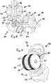
- Fig. 1shows an exploded view of a first embodiment of the external fixation component of the present invention.
- the external fixation componentcomprises three elements.
- There is a first capture member 10which is a clamping assembly.
- Said first capture member 10is connected to a central rotation member 30 which is in turn connected to the second capture member 20, being a second clamping assembly.
- different capture memberscan be used in connection with the central rotation member 30 as well as clamping assemblies from prior art if an adapted central locking screw and shaft is used.
- the first capture member 10comprises a first jaw 11 and a second jaw 12 having central bores 21 and 22, respective.
- a screw 40 with a central shaft for locking the clamping assembly 10is introduced through said bores 21 and 22.
- Shaft 40enters the first jaw through a locking element 50 which is lodged in the rounded recess 24 of first jaw 11.
- the shaft 40comprises a head 42 for actuating the screw, a proximal flange portion 43 followed by a reduced diameter portion 44, and it ends in a thread portion 49.
- said central shaft 40defines the longitudinal axis 46 of clamping assembly 10.
- the underside of the second jaw 12comprises an anti rotation surface, e.g. radially oriented grooves around the central bore 22. This could also be a hard foam insert having such a surface 45 or another specific inlay.
- the second capture member 20 of the embodiment according to Fig. 1comprises identical features compared to the first capture member 10 within this embodiment. Therefore a specific description of said second capture member 20 is omitted.
- Fig. 2shows an assembled view of the embodiment according to Fig. 1 , within which it can be seen, that each capture member 10 and 20 comprise three different receptions 71, 72 and 73 for accommodating different sized rods or pins of an external fixator system.
- the two capture members 10 and 20are connected via the thread portion 49 of the screw with the central rotating member 30.
- the rotation member 30comprises a central disc 61 having a shaft 81 and a complementary disc 62 comprising an inner central bore 84 to accommodate shaft 81 with its outer thread 82.
- Shaft 81defines the rotational axis of the rotation member 30.
- the longitudinal axes 46 of both capture members 10 and 20, connected by the rotation member 30,intersect in the middle between the discs 61 and 62 on the axis defined by shaft 81.
- Shaft 81is thus oriented perpendicular to the plane spanned by the axes 46.
- the width defined by the distance between the discs 61 and 62is not larger than the dimension of the capture members 10 and 20 around axis 46.
- Shaft 81can be adapted to provide an inner abutment surface, when disc 62 is completely screwed on disc 61. It is also possible that the connection between discs 61 and 62 is glued, soldered, riveted etc. It is not necessary that the discs 61 and 62 can be separated. In a different embodiment shaft 81 can also be non-unitary with disc 61 and therefore both discs 61 and 62 would be attached at shaft 81.
- the outer rolling surface 85 of the discs 61 and 62is preferably made up or covered by an anti rotation surface, e.g. grooves tangential to the cylindrical surface of the discs.
- Both discs 61 and 62comprise a circular ring undercut 83 oriented to the inside providing an inner cylindrical abutment surface 88 allowing introducing a first nut 65 having a central bore 31 between the discs 61, 62.
- the underside 33 of the first nut 65is preferably planar as are the side surfaces, wherein the upper surface 32 is rounded complementary to the abutment surface 88 of the discs 61, 62.
- the outer threaded portion 49 of the screw 40is adapted to be screwed into a complementary inner thread within the bore 31 of the first nut 65 of rotation member 30.
- Rotation member 30is connected via first rotation blocker 63 to the first capture member 10.
- Said first rotation blocker 63comprises an inner central bore 41 for the shaft 40 as well as a preferably level upper surface 55, at least partly complementary to the anti rotation surface 45 of the capture member 10.
- First rotation blocker 63furthermore comprises a anti rotation blocker surface 86 provided opposite to the level upper surface 55.
- Said anti rotation blocker surface 86is at least a partly inner cylindrical surface having a curvature complementary to the curvature of the rolling surface of the two discs 61 and 62.
- the length of the shaft 40is adapted to be screwed into the complementary inner thread within bore 31 after traversing bore 41 of the first rotation blocker 63 (and jaws 11 and 12).
- the length of the shaft 40is such that, if the capture member 10 is completely closed, the bottom of screw 40 does not touch the central shaft 81 of the rotation member 30.
- the capture members 10 and 20each comprise a spring 15 positioned along the longitudinal axis of the screw 40 around the reduced diameter shaft 44 between the respective rotation blocker 63 or 64 and the second jaw 12.
- the rotation member 30Beside the central discs 61, 62 with shaft 81 forming the rolling surface and clamping surface providing element the rotation member 30 comprises two blocking elements 65 and 66 connected with the capture member 10 and 20, respectively, via the locking screw 40 as well as two rotation blockers 63 and 64 providing the interface surface 55 with the capture members 10 and 20, respectively.
- Fig. 3shows a view from above on the embodiment according to Fig. 1 providing visualization of the two cross-section views of Fig. 4 and 5 along lines IV-IV and V-V, respectively.
- Identical reference numeralsare used for identical or similar features within all embodiments throughout all drawings.
- Fig. 3shows that locking element 50 has a lateral opening allowing retrieval of the locking element 50, if the screw 40 is loosened to withdraw element 50 from the rounded recess 24.
- Screw 40has a flange 43 positioned inside jaw 11 allowing a translational movement of jaw 11 and even a withdrawal of jaw 11, if the locking element 50 is removed; but second jaw 12 having a smaller dimension bore 22 cannot be removed. Therefore the fixation element 10 remains partly assembled for easy cleaning of the interstitial cavities.
- Spring 15is provided within a spring reception 16 in jaw 12 and within spring reception 67 in the rotation blocker 63 and 64, respectively. These springs 15 enable the practitioner using the element to freely rotate capture member 10 or 20 around longitudinal axis 46 and this independently for each capture member 10 or 20. In other embodiments, not shown in the drawings, there can be provided such a spring between jaws 11 and 12 of a or each capture member 10 or 20 or between rotation blockers 63, 64 and disc 61, 62 or nuts 65, 66 respectively. In such a case the rotation around the shaft axis 81 would be easily enabled, still allowing snapping in of rods into receptions 71, 72 and 73.
- Spring 15 as shown in these embodimentsis a compression spring. It is also possible to provide one or a pack of Belleville washers as a spring element. In other embodiments elastic foams can be used.
- Rotation member 30comprises the partly hollow discs 61 and 62, wherein the circular ring undercut 83 provides the abutment surface of the upper rounded surface 32 of the nuts 65 and 66, respectively.
- surfaces 32are shown as cylindrical complementary to the undercut surface it is clear that said complementary surface 32 is only mandatory for the portions reaching under the disc edges, wherein the zone around the hole 31 can be configured differently.
- the nuts 65 and 66have portions reaching in the interspace between the discs up to surface 85.
- the planar underside 33 of the nuts 65 and 66, respectivelyare cylindrical or reach until the central shaft.
- the complementary interface surfaces 45 and 55 of the capture members 10, 20 and rotation blocker 63, 64, respectivelyare essentially planar in a plane perpendicular to the axis 46 of the respective capture member 10, 20.
- the end portions of screw threads 49are destroyed, so that the nut 65 or 66 cannot be removed from the screw 40 of the capture member 10 or 20, respectively.
- Fig. 6shows a cross-section of an embodiment similar to Fig. 1 , but omitting the springs 15, wherein the capture members 10, 20 are rotated close one to the other.
- Fig. 7shows a perspective view of the position of the external fixation element in Fig. 6 .
- the capture members 10 and 20are rotated in such a way that their longitudinal axes 46 are in a right angle when looking in the plane of the discs 61, 62. At this angle, the edges of the lower planar surfaces 33 of the nuts 65 and 66 come into contact and limit a further rotational movement.
- Fig. 6 and 7show that the external fixation element is easy to handle.
- a rod or pinis snapped, e.g. into reception 71 in first capture member 10.
- Fig. 8shows a perspective view of a second embodiment according to the invention, wherein a further capture member 110 is provided.
- Said further capture member 110is a multipin capture member having four receptions 111 for pins.
- the receptions 111are provided as parallel grooves, but also oblique grooves are possible.
- Beside central screw 40having the same function as in the first mentioned embodiment, there are two multipin fixation screws 112 to clamp jaws 11 and 12 of this embodiment.
- Lower jaw 12comprises the anti-rotation interface surface 45 being in contact with blocking member 64 of the rotation member 30.
- Fig. 9shows a perspective view of a further different embodiment of the invention, showing a different additional capture member 120.
- Said capture member 120is provided with a plurality of pin grooves 121 between jaws 11 and 12, wherein the multipin clamp is closed using one central multipin fixation screw 122 as well as two lateral fixation screws 40. These screws 40 are provided to attach two rotation members 30 being in contact with one first capture member 10 each, which can be oriented in any direction due to the three rotational interfaces.
- Fig. 10shows a perspective view of a fifth embodiment of the invention, wherein Fig. 11 and 12 show cross-sections of the embodiment according to Fig. 10 .
- the external fixation element according to Fig. 10comprises a first capture member 10 and a second capture member 20, wherein different clamping assemblies are used, providing three different receptions 71, 72 and 73 for rods or pins.
- the capture members 10, 20are connected to the rotation member 130 via central shafts 40 traversing rotation blockers 63 and 64 comprising an anti rotation blocker surface 86.
- the central shafts 40comprise an internal thread for accommodating counter screws 165 and 166, respectively. Heads of the counter screws 165 and 166 are lodged in the disc elements 161, 162, respectively.
- the disc elements 161 and 162are different to the discs 61 and 62, but have the common feature of a curved outer rolling surface 85 being opposite to anti rotation blocker surface 86 in blockers 63 and 64.
- the two discs 161 and 162, having the form of a circular segment in cross section,are connected together via two fixation plates 131 joining the two parts.
- a central hollow spring 15is provided around shaft 40 between rotation blockers 63 and 64 and jaw 12.
- the disc elements 161 and 162provide a circular surface to allow rotation of the corresponding capture member about an axis which is here not located in the centre axis 81 of the rotation member 130 but below and opposite the centre.
- the rotationcan be performed by about +- 30 degrees to the left and to the right around the position shown in Fig. 11 .
- the two capture members 10 and 20can only positioned in an angle of 120 degrees and not in an angle of 90 degree as shown in Figs. 6 and 7 .
- a counter screw 165, 166instead of a counter nut 65, 66.
- These screws 165, 166are positioned crossing a slit within the discs 161, 162, and a through bore 41 in blockers 63 and 64, respectively, while the hollow shaft 40 abuts against an upper surface of the blocker 63 or 64.
- the advantage of the screws 165, 166is that their heads are blocked from leaving the central rotation body formed by disc portions 161 and 162. Turning shaft 40 only advances the engagement of the threads of shaft 40 and screw 165, 166.
- shaft 40is still called a central locking screw 40 since the shaft comprises an inner thread 149. Therefore element 40 provides a screw in connection with counter screw 165, 166.
- the combination screw 40 and counter nut 65, 66is used with the (cylindrical) disc elements 61 and 62, and in a different embodiment the shaft 40 and counter screws 165, 166 is used with the (circular segment) disc elements 161 and 162, it is clear for some one skilled in the art that the screw 40 + counter nut 65 combination can be used with the discs 161, 162 and the shaft 40 + counter screw 165 combination can be used with the discs 61, 62.
- the external fixation elementcomprising the capture members 10, 20, 110 and 120 are made e.g. in stainless steel, titanium, ceramics or plastics depending on the application field of the external fixation element.
- the receptions 71, 72, 73, 111, 121can accommodate different sized pins, rods, bars, Schanz screws or Kirschner wires, depending on the application of the external fixation element (upper limbs, lower limbs, size of the patient etc.).
Landscapes
- Health & Medical Sciences (AREA)
- Orthopedic Medicine & Surgery (AREA)
- Life Sciences & Earth Sciences (AREA)
- Surgery (AREA)
- Biomedical Technology (AREA)
- Engineering & Computer Science (AREA)
- Nuclear Medicine, Radiotherapy & Molecular Imaging (AREA)
- Heart & Thoracic Surgery (AREA)
- Medical Informatics (AREA)
- Molecular Biology (AREA)
- Animal Behavior & Ethology (AREA)
- General Health & Medical Sciences (AREA)
- Public Health (AREA)
- Veterinary Medicine (AREA)
- Surgical Instruments (AREA)
Description
- The present invention relates to an external fixation component comprising a first capture member adapted to capture a first element of an external fixation system and a second capture member adapted to capture a second element of an external fixation system; and a rotation member, coupled to the first capture member and to the second capture member such that the coupling allows the two capture members to rotate about three axes relative to each other.
- External fixation systems are widely used in orthopedics to connect two or more bone fragments to each other. Such orthopedic fixation systems comprise bone screws, pins, wires which are inserted directly into the bone material and these systems use external structural elements as fixation rods, bars and pin. In order to connect the rods and bars to form a rigid frame, different capture members and fixation clamps are used. Furthermore, said fixation clamps are used to connect the screws and pins to the rigid frame to specifically hold bone fragments at an intended place.
- One adjustable fixation clamp showing the features of the preamble of the independent claims is known from
EP 0 700 664 comprising two clamping assemblies or capture members as pairs of jaws allowing clamping of a rod as well as of a pin. - A clamping assembly for multiple rod-shaped elements is known from
EP 1 627 609 having one single pair of jaws. However, such a clamp allows clamping more than two, e.g. three or four rod-shaped elements as pins with one single clamp, thus reducing the number of clamps. However, one further fixation clamp is necessary to fix the rod of said clamp to the frame of the fixation system, usually these clamping assemblies comprise a rod which is then attached to the frame using a separate adjustable fixation clamp. - The known adjustable fixation clamp from
EP 0 700 664 allows two rods or elements to be clamped to be positioned in any angular position when rotated about the longitudinal axis of the device. Said device does not allow inclining one clamping assembly against the other clamping assembly in view of said longitudinal axis of the device. EP 1 471 82A - Further similar external fixation components are known from
US 5,160,335 as well as fromUS 2009/008751 A1 . - The external fixation element according to the prior art provides a complicated rotation member which is directly connected to the capture members which element is difficult to clean and do not provide a versatile use with a plurality of different capture members.
- It is therefore an object of the invention to overcome this problem and to provide an external fixation component adapted for a variety of capture elements, especially a single rod clamp as shown in
EP 0 700 664 , so called multi pin clamps as shown inEP 1 627 609 , or different capture elements. It is an object of the invention to provide three rotational axes for two capture elements in a smaller space, especially providing the three rotational axes crossing in one point in space. - Such a device is achieved with the external fixation element having the characterizing features of claim 1 or of
claim 2. - An external fixation component comprises two capture members adapted to capture independently a first and a second element of an external fixation system. Between them a rotation member is provided, coupled to both capture members such that the coupling allows the two capture members to rotate about three axes relative to each other. Each capture member comprises a central locking screw extending there through and defining a longitudinal axis of the associated capture member. The rotation member comprises two rotation blockers, each blocker providing one interface surface adapted to be in contact with a complementary interface surface of one of the capture members, each blocker further providing a surface opposite to said interface surface comprising an inner cylindrical surface. The rotation member comprises a central disc element forming a rolling surface as complementary surface to said inner cylindrical surface of the corresponding rotation blocker and it comprises two nuts, wherein each nut is associated to one locking screw of a corresponding capture member and wherein each locking screw of a capture member is extending through the corresponding rotation blocker and engages the corresponding nut for an individual locking of each capture member.
- It is an advantage of the fixation element according to the invention that after having clamped one pin or rod with one clamping assembly or capture member, a practitioner willing to attach subsequently a rod to a second clamping assembly of the element can freely turn, rotate and push said second clamping assembly in any direction in the 3D space without losing the first mentioned pin or rod pre-clamped in the first capture member. It is a further advantage that due to the spring actuated first and second clamping assemblies they can be handled easily without fixed clamping and maintain the rods in place. It is especially an advantage to use the clamps having the triangular structure according to this specification allowing accommodation of different rod diameter within a single capture member. The practitioner can check the robustness of his external fixator and if he finds that the rod he has used is not stiff enough, he simply opens the single clamping assembly containing said rod, removes said thinner rod, turns the clamping assembly by 120 degrees in one or the other direction around the longitudinal axis of said capture member and snaps and clamps a new thicker fixation rod replacing the original rod.
- Further embodiments of the invention are laid down in the dependent claims.
- Preferred embodiments of the invention are described in the following with reference to the drawings, which are for the purpose of illustrating the present preferred embodiments of the invention and not for the purpose of limiting the same. In the drawings,
- Fig. 1
- shows an exploded view of a first embodiment of the external fixation component of the present invention,
- Fig. 2
- shows an assembled view of the embodiment according to
Fig. 1 , - Fig. 3
- shows a view from above on the embodiment according to
Fig. 1 , - Fig. 4
- shows a cross-section of the embodiment according to
Fig. 1 along line IV-IV inFig. 3 , - Fig. 5
- shows a cross-section of the embodiment according to
Fig. 1 along line V-V inFig. 3 , - Fig. 6
- shows a cross-section of a second embodiment similar to the embodiment of
Fig. 1 , omitting springs, wherein the capture members are rotated close one to the other, - Fig. 7
- shows a perspective view of the position of the element in
Fig. 6 , - Fig. 8
- shows a perspective view of a third embodiment according to the invention,
- Fig. 9
- shows a perspective view of a fourth embodiment of the invention,
- Fig. 10
- shows a perspective view of a fifth embodiment of the invention,
- Fig. 11
- shows one cross-section of the embodiment according to
Fig. 10 , and - Fig. 12
- shows a further cross-section of the embodiment according to
Fig. 10 . Fig. 1 shows an exploded view of a first embodiment of the external fixation component of the present invention. The external fixation component comprises three elements. There is afirst capture member 10 which is a clamping assembly. Saidfirst capture member 10 is connected to acentral rotation member 30 which is in turn connected to thesecond capture member 20, being a second clamping assembly. As will be seen in connection withFig. 8 and9 , different capture members can be used in connection with thecentral rotation member 30 as well as clamping assemblies from prior art if an adapted central locking screw and shaft is used.- The
first capture member 10 comprises afirst jaw 11 and asecond jaw 12 havingcentral bores screw 40 with a central shaft for locking the clampingassembly 10 is introduced through said bores 21 and 22.Shaft 40 enters the first jaw through a lockingelement 50 which is lodged in therounded recess 24 offirst jaw 11. Theshaft 40 comprises ahead 42 for actuating the screw, aproximal flange portion 43 followed by a reduced diameter portion 44, and it ends in athread portion 49. As can be seen inFig. 4 or5 saidcentral shaft 40 defines thelongitudinal axis 46 of clampingassembly 10. Preferably the underside of thesecond jaw 12 comprises an anti rotation surface, e.g. radially oriented grooves around thecentral bore 22. This could also be a hard foam insert having such asurface 45 or another specific inlay. - The
second capture member 20 of the embodiment according toFig. 1 comprises identical features compared to thefirst capture member 10 within this embodiment. Therefore a specific description of saidsecond capture member 20 is omitted. Fig. 2 shows an assembled view of the embodiment according toFig. 1 , within which it can be seen, that eachcapture member different receptions - The two
capture members thread portion 49 of the screw with the central rotatingmember 30. Therotation member 30 comprises acentral disc 61 having ashaft 81 and acomplementary disc 62 comprising an inner central bore 84 to accommodateshaft 81 with its outer thread 82.Shaft 81 defines the rotational axis of therotation member 30. Thelongitudinal axes 46 of bothcapture members rotation member 30, intersect in the middle between thediscs shaft 81.Shaft 81 is thus oriented perpendicular to the plane spanned by theaxes 46. Preferably the width defined by the distance between thediscs capture members axis 46. Shaft 81 can be adapted to provide an inner abutment surface, whendisc 62 is completely screwed ondisc 61. It is also possible that the connection betweendiscs discs different embodiment shaft 81 can also be non-unitary withdisc 61 and therefore bothdiscs shaft 81. The outer rollingsurface 85 of thediscs discs cylindrical abutment surface 88 allowing introducing afirst nut 65 having a central bore 31 between thediscs underside 33 of thefirst nut 65 is preferably planar as are the side surfaces, wherein theupper surface 32 is rounded complementary to theabutment surface 88 of thediscs - The outer threaded
portion 49 of thescrew 40 is adapted to be screwed into a complementary inner thread within the bore 31 of thefirst nut 65 ofrotation member 30. Rotation member 30 is connected viafirst rotation blocker 63 to thefirst capture member 10. Saidfirst rotation blocker 63 comprises an innercentral bore 41 for theshaft 40 as well as a preferably levelupper surface 55, at least partly complementary to theanti rotation surface 45 of thecapture member 10.First rotation blocker 63 furthermore comprises a antirotation blocker surface 86 provided opposite to the levelupper surface 55. Said antirotation blocker surface 86 is at least a partly inner cylindrical surface having a curvature complementary to the curvature of the rolling surface of the twodiscs - The length of the
shaft 40 is adapted to be screwed into the complementary inner thread within bore 31 after traversing bore 41 of the first rotation blocker 63 (andjaws 11 and 12). The length of theshaft 40 is such that, if thecapture member 10 is completely closed, the bottom ofscrew 40 does not touch thecentral shaft 81 of therotation member 30. - In the embodiment shown in
Figs. 1 and 2 , thecapture members spring 15 positioned along the longitudinal axis of thescrew 40 around the reduced diameter shaft 44 between therespective rotation blocker second jaw 12. Thus it can be ensured that initially pins or rods can be readily snapped intoreceptions jaws respective spring 15. Even before thecapture member spring 15 pushes the two blockingsurfaces rotation blocker elements - Beside the
central discs shaft 81 forming the rolling surface and clamping surface providing element therotation member 30 comprises two blockingelements capture member screw 40 as well as tworotation blockers interface surface 55 with thecapture members Fig. 3 shows a view from above on the embodiment according toFig. 1 providing visualization of the two cross-section views ofFig. 4 and5 along lines IV-IV and V-V, respectively. Identical reference numerals are used for identical or similar features within all embodiments throughout all drawings.Fig. 3 shows that lockingelement 50 has a lateral opening allowing retrieval of the lockingelement 50, if thescrew 40 is loosened to withdrawelement 50 from the roundedrecess 24.Screw 40 has aflange 43 positioned insidejaw 11 allowing a translational movement ofjaw 11 and even a withdrawal ofjaw 11, if the lockingelement 50 is removed; butsecond jaw 12 having a smaller dimension bore 22 cannot be removed. Therefore thefixation element 10 remains partly assembled for easy cleaning of the interstitial cavities.Spring 15 is provided within aspring reception 16 injaw 12 and withinspring reception 67 in therotation blocker springs 15 enable the practitioner using the element to freely rotatecapture member longitudinal axis 46 and this independently for eachcapture member jaws capture member rotation blockers disc nuts shaft axis 81 would be easily enabled, still allowing snapping in of rods intoreceptions Spring 15 as shown in these embodiments is a compression spring. It is also possible to provide one or a pack of Belleville washers as a spring element. In other embodiments elastic foams can be used.Rotation member 30 comprises the partlyhollow discs rounded surface 32 of the nuts 65 and 66, respectively. Althoughsurfaces 32 are shown as cylindrical complementary to the undercut surface it is clear that saidcomplementary surface 32 is only mandatory for the portions reaching under the disc edges, wherein the zone around the hole 31 can be configured differently. It is possible that the nuts 65 and 66 have portions reaching in the interspace between the discs up to surface 85. On the other hand it is also possible that theplanar underside 33 of the nuts 65 and 66, respectively, are cylindrical or reach until the central shaft. Preferably the complementary interface surfaces 45 and 55 of thecapture members rotation blocker axis 46 of therespective capture member - In one embodiment, the end portions of
screw threads 49 are destroyed, so that thenut screw 40 of thecapture member nut axis 46, the nuts are removed from the space inside thediscs Fig. 6 shows a cross-section of an embodiment similar toFig. 1 , but omitting thesprings 15, wherein thecapture members Fig. 7 shows a perspective view of the position of the external fixation element inFig. 6 . Thecapture members longitudinal axes 46 are in a right angle when looking in the plane of thediscs planar surfaces 33 of the nuts 65 and 66 come into contact and limit a further rotational movement. However,Fig. 6 and 7 show that the external fixation element is easy to handle. A rod or pin is snapped, e.g. intoreception 71 infirst capture member 10. Then the correspondingscrew 40 is slightly tightened, thus bringing the interface surfaces 45, 55 ofelements axis 46 of thefirst capture member 10. Furthermore blockingsurfaces element 63 anddiscs screw 40 offirst capture member 10 in the angular correct position for further building of an external fixation frame. Then a second rod or pin is e.g. snapped into thereception 72 of thesecond capture member 20, after rotation of the second capture member around its own axis 46 (againstsurfaces 45, 55) as well as around the rollingsurface 86 of thediscs surface 85 of theelement 64. Then thissecond screw 40 ofsecond capture member 20 is tightened and the frame is fixed.Fig. 8 shows a perspective view of a second embodiment according to the invention, wherein afurther capture member 110 is provided. Saidfurther capture member 110 is a multipin capture member having four receptions 111 for pins. The receptions 111 are provided as parallel grooves, but also oblique grooves are possible. Besidecentral screw 40 having the same function as in the first mentioned embodiment, there are two multipin fixation screws 112 to clampjaws Lower jaw 12 comprises theanti-rotation interface surface 45 being in contact with blockingmember 64 of therotation member 30.Fig. 9 shows a perspective view of a further different embodiment of the invention, showing a differentadditional capture member 120. Saidcapture member 120 is provided with a plurality ofpin grooves 121 betweenjaws multipin fixation screw 122 as well as two lateral fixation screws 40. Thesescrews 40 are provided to attach tworotation members 30 being in contact with onefirst capture member 10 each, which can be oriented in any direction due to the three rotational interfaces.Fig. 10 shows a perspective view of a fifth embodiment of the invention, whereinFig. 11 and 12 show cross-sections of the embodiment according toFig. 10 . The external fixation element according toFig. 10 comprises afirst capture member 10 and asecond capture member 20, wherein different clamping assemblies are used, providing threedifferent receptions capture members rotation member 130 viacentral shafts 40traversing rotation blockers rotation blocker surface 86. Thecentral shafts 40 comprise an internal thread for accommodating counter screws 165 and 166, respectively. Heads of the counter screws 165 and 166 are lodged in thedisc elements - The
disc elements discs surface 85 being opposite to antirotation blocker surface 86 inblockers discs fixation plates 131 joining the two parts. As in the embodiment shown above, a centralhollow spring 15 is provided aroundshaft 40 betweenrotation blockers jaw 12. Thedisc elements centre axis 81 of therotation member 130 but below and opposite the centre. This allows for a lesser height of the overall fixation element but of course restricts the possibility of any rotation. Here, the rotation can be performed by about +- 30 degrees to the left and to the right around the position shown inFig. 11 . Thus the twocapture members Figs. 6 and 7 . - One further difference between the embodiments of
Fig. 1 andFig. 10 is the provision of acounter screw counter nut screws discs bore 41 inblockers hollow shaft 40 abuts against an upper surface of theblocker screws disc portions shaft 40 only advances the engagement of the threads ofshaft 40 andscrew shaft 40 is still called acentral locking screw 40 since the shaft comprises aninner thread 149. Thereforeelement 40 provides a screw in connection withcounter screw - In one of the embodiments of the drawings the
combination screw 40 andcounter nut disc elements shaft 40 and counter screws 165, 166 is used with the (circular segment)disc elements screw 40 +counter nut 65 combination can be used with thediscs shaft 40 +counter screw 165 combination can be used with thediscs - The external fixation element comprising the
capture members receptions LIST OF REFERENCE SIGNS 10 first capture member / clamping assembly 22 bore 24 rounded recess 11 first jaw 30 rotation member 12 second jaw 31 bore 15 spring 32 upper surface 16 spring reception 33 lower surface 20 second capture member / clamping assembly 40 central shaft 41 central bore 21 enlarged bore 42 head 43 proximal portion 83 undercut 44 reduced diameter portion 84 bore with thread 45 anti rotation surface 85 outer rolling surface 46 longitudinal axis of 10 or 20 86 anti rotation blocker surface 49 thread portion 88 cylindrical abutment surface 50 locking element 110 further capture member 55 level upper surface 111 receptions 59 side opening 112 multipin fixation screw 61 first disc (with shaft) 120 additional capture member 62 second wheel 121 pin grooves 63 first rotation blocker 122 multipin fixation screw 64 second rotation blocker 130 rotation member 65 first nut 131 fixation plate 66 second nut 149 inner thread of 40 67 spring reception 161 disc 71 first reception 162 disc 72 second reception 165 first counter screw 73 third reception 166 second counter screw 81 shaft 82 thread
Claims (7)
- External fixation component comprising a first capture member (10) adapted to capture a first element of an external fixation system and a second capture member (20, 110, 120) adapted to capture a second element of an external fixation system; and a rotation member (30), coupled to the first capture member (10) and to the second capture member (20, 110. 120) such that the coupling allows the two capture members (10, 20, 110, 120) to rotate about three axes (46, 46, 81) relative to each other, whereas each capture member (10, 20, 110, 120) comprises a central locking screw (40) extending therethrough and defining a longitudinal axis (46) of the associated capture member (10, 20, 110, 120), whereas the rotation member (30) comprises two rotation blockers (63, 64), each blocker (63, 64) providing a first interface surface (55) adapted to be in contact with a complementary second interface surface (45) of one of the capture members (10, 20, 110, 120), whereas each rotation blocker (63, 64) comprises a surface opposite to said first interface surface (55) comprising an inner cylindrical surface (86), whereas the rotation member (30) further comprises a central disc element (61, 62), the central disc element comprising a central axis (81) and forming an outer rolling surface (85) as complementary surface to the inner cylindrical surface (86) of the corresponding rotation blocker (63, 64), the central disc element allowing rotation of the corresponding capture element (10, 20, 110, 120) around the axis (81) of the central disc element (61, 62), wherein the rotation member (30) comprises two counter elements (65, 66), wherein each counter element (65, 66) is associated to one of said locking screw (40) of a corresponding capture member (10, 20, 110, 120) and wherein each locking screw (40) of a capture member (10, 20, 110, 120) is extending through the corresponding rotation blocker (63, 64) and engages the corresponding counter element (65, 66) for an individual locking of each capture member (10, 20, 110, 120),characterized in that the central disc element (61, 62) comprises two lateral cylindrical discs (61, 62) defining an interspace between them, wherein each cylindrical disc (61, 62) comprises a circular ring undercut (83) to accommodate lateral parts of the counter elements (65, 66) in said interspace, wherein each counter element (65, 66) has a cylindrical segment as upper surface (32) to block, upon tightening of the associated screw (40), the first and second interface surfaces (45, 55) between the capture member (10, 20, 110, 120) and the rotation blocker (63, 64) as well as the upper surface (32) and the undercut (83) against a rotational movement around the corresponding axes (46, 81).
- External fixation component comprising a first capture member (10) adapted to capture a first element of an external fixation system and a second capture member (20, 110, 120) adapted to capture a second element of an external fixation system; and a rotation member (130), coupled to the first capture member (10) and to the second capture member (20, 110, 120) such that the coupling allows the two capture members (10, 20, 110, 120) to rotate about three axes (46, 46) relative to each other, whereas each capture member (10, 20) comprises a central locking screw (40) extending there through and defining a longitudinal axis (46) of the associated capture member (10, 20, 110, 120), whereas the rotation member (130) comprises two rotation blockers (63, 64), each blocker (63, 64) providing a first interface surface (55) adapted to be in contact with a complementary second interface surface (45) of one of the capture members (10, 20, 110, 120), whereas each rotation blocker (63, 64) comprises a surface opposite to said first interface surface (55) comprising an inner cylindrical surface (86), whereas the rotation member (130) further comprises a central disc element (161, 162) forming an outer rolling surface (85) as complementary surface to the inner cylindrical surface (86) of the corresponding rotation blocker (63, 64) allowing rotation of the corresponding capture element (10, 20, 110, 120) around an axis of the central disc element (61, 62), wherein the rotation member (130) comprises two counter elements (165, 166), wherein each counter element (165, 166) is associated to one of said locking screw (40) of a corresponding capture member (10, 20, 110, 120) and wherein each locking screw (40) of a capture member (10, 20, 110, 120) is extending through the corresponding rotation blocker (63, 64) and engages the corresponding counter element (165, 166) for an individual locking of each capture member (10, 20, 110, 120),characterized in that the central disc element (161, 162) comprises an upper and a lower disc having the form of a circular segment in cross-section and each disk having a slit in the circumference of said segment to accommodate a respective flange surface of the respective counter elements (165, 166), wherein each counter element (165, 166) has a cylindrical segment as upper surface (32) to block, upon tightening of the associated screw (40), the first and second interface surfaces (45, 55) between the respective capture member (10, 20, 110, 120) and the respective rotation blocker (63, 64) as well as the respective upper surface (32) and an undercut (83) of the respective disc elements against a rotational movement around the corresponding axes (46).
- External fixation component according to claim 1, wherein the counter element (65, 66) is a nut and the locking screw (40) comprises an outer thread for the locking engagement with the nut, wherein each nut (65, 66) comprises a central bore (31) having a thread to accommodate the locking screw (40) of the corresponding capture member (10, 20, 110, 120).
- External fixation component according to claim 2, wherein the counter element (165, 166) is a counter screw and the locking screw (40) comprises an inner thread for the locking engagement with the counter screw.
- External fixation component according to one of claim 1 to 4, wherein said first and second interface surfaces (45, 55) between the capture member (10, 20) and the rotation blocker (63, 64) are perpendicular to said longitudinal axis (46) for a rotation about said axis (46).
- External fixation component according to claim 1 to 5, wherein the first and second interface surfaces (45, 55) between the capture member (10, 20) and the rotation blocker (63, 64) comprise radial grooves around the central through going bore (22, 41) in the capture member (10, 20) as well as in the rotation blocker (63, 64).
- External fixation component according to claim 1 to 6, wherein the rolling surface (85) of the central disc element (61, 62 or 161, 162) comprises engaging grooves oriented in the longitudinal direction of the shaft (81) of the central disc element (61, 62 or 161, 162) and wherein complementary grooves are provided in each rotation blocker (63, 64) on an inner cylindrical surface (86).
Priority Applications (7)
| Application Number | Priority Date | Filing Date | Title |
|---|---|---|---|
| EP09170102.9AEP2294994B1 (en) | 2009-09-11 | 2009-09-11 | External fixation component |
| ES09170102.9TES2668075T3 (en) | 2009-09-11 | 2009-09-11 | External fixation component |
| US12/653,975US8172840B2 (en) | 2009-09-11 | 2009-12-21 | External fixation component |
| CA2710738ACA2710738C (en) | 2009-09-11 | 2010-07-22 | External fixation component |
| AU2010203309AAU2010203309B2 (en) | 2009-09-11 | 2010-07-26 | External fixation component |
| CN201010270933.4ACN102018556B (en) | 2009-09-11 | 2010-09-01 | External fixation component |
| JP2010202843AJP5558980B2 (en) | 2009-09-11 | 2010-09-10 | External fixing component |
Applications Claiming Priority (1)
| Application Number | Priority Date | Filing Date | Title |
|---|---|---|---|
| EP09170102.9AEP2294994B1 (en) | 2009-09-11 | 2009-09-11 | External fixation component |
Publications (2)
| Publication Number | Publication Date |
|---|---|
| EP2294994A1 EP2294994A1 (en) | 2011-03-16 |
| EP2294994B1true EP2294994B1 (en) | 2018-04-04 |
Family
ID=41571520
Family Applications (1)
| Application Number | Title | Priority Date | Filing Date |
|---|---|---|---|
| EP09170102.9AActiveEP2294994B1 (en) | 2009-09-11 | 2009-09-11 | External fixation component |
Country Status (7)
| Country | Link |
|---|---|
| US (1) | US8172840B2 (en) |
| EP (1) | EP2294994B1 (en) |
| JP (1) | JP5558980B2 (en) |
| CN (1) | CN102018556B (en) |
| AU (1) | AU2010203309B2 (en) |
| CA (1) | CA2710738C (en) |
| ES (1) | ES2668075T3 (en) |
Families Citing this family (49)
| Publication number | Priority date | Publication date | Assignee | Title |
|---|---|---|---|---|
| US7708736B2 (en) | 2006-02-22 | 2010-05-04 | Extraortho, Inc. | Articulation apparatus for external fixation device |
| EP1920720B1 (en)* | 2006-10-13 | 2014-03-19 | Stryker Trauma SA | Prevention of re-use of a medical device |
| EP2197372B1 (en) | 2007-09-27 | 2016-04-13 | Zimmer, Inc. | Clamping apparatus for external fixation and stabilization |
| US8858555B2 (en) | 2009-10-05 | 2014-10-14 | Stryker Trauma Sa | Dynamic external fixator and methods for use |
| US9138260B2 (en) | 2010-07-01 | 2015-09-22 | Zimmer, Inc. | Multi-locking external fixation clamp |
| BR112013002146A2 (en) | 2010-07-30 | 2016-05-31 | Smith & Nephew Inc | double acting external clamp |
| US8945128B2 (en) | 2010-08-11 | 2015-02-03 | Stryker Trauma Sa | External fixator system |
| US11141196B2 (en) | 2010-08-11 | 2021-10-12 | Stryker European Operations Holdings Llc | External fixator system |
| EP2417924B1 (en) | 2010-08-11 | 2015-07-01 | Stryker Trauma SA | External fixator system |
| ES2541831T3 (en)* | 2010-10-07 | 2015-07-27 | Stryker Trauma Sa | Coupling element for an external fixing device |
| WO2012051312A1 (en)* | 2010-10-12 | 2012-04-19 | Extraortho, Inc. | Single lock external fixation clamp arrangement |
| WO2012051255A1 (en)* | 2010-10-12 | 2012-04-19 | Extraortho, Inc. | External fixation surgical clamp with swivel |
| US8728078B2 (en) | 2010-11-04 | 2014-05-20 | Zimmer, Inc. | Clamping assembly with links |
| WO2012078897A1 (en) | 2010-12-09 | 2012-06-14 | Extraortho, Inc. | Revolving lock for external fixation clamps |
| EP2648633B1 (en) | 2010-12-09 | 2016-05-18 | Zimmer, Inc. | External fixation clamp with cam driven jaw |
| USD704840S1 (en) | 2010-12-14 | 2014-05-13 | Stryker Trauma Sa | Hinge coupling |
| EP2465454B1 (en) | 2010-12-14 | 2015-04-08 | Stryker Trauma SA | Fixation clamp with thumbwheel |
| USD720853S1 (en) | 2010-12-14 | 2015-01-06 | Stryker Trauma Sa | Fixation clamp |
| ES2540256T3 (en) | 2010-12-14 | 2015-07-09 | Stryker Trauma Sa | Fixing clamp |
| EP2465455B1 (en) | 2010-12-14 | 2015-04-08 | Stryker Trauma SA | Fixation clamp |
| USD683461S1 (en) | 2010-12-14 | 2013-05-28 | Stryker Trauma Sa | Hinge coupling |
| JP6106662B2 (en) | 2011-05-17 | 2017-04-05 | ジンマー,インコーポレイティド | External fixed clamping system using a starting mechanism and stored spring energy |
| USD682426S1 (en)* | 2011-06-14 | 2013-05-14 | Stryker Trauma Sa | Fixation clamp |
| USD663030S1 (en)* | 2011-06-14 | 2012-07-03 | Styker Trauma SA | Fixation clamp |
| ES2581533T3 (en)* | 2011-12-06 | 2016-09-06 | Stryker European Holdings I, Llc | Fixing clamp |
| ITRM20120205A1 (en)* | 2012-05-10 | 2013-11-11 | Yordanova Radoslava | UNIVERSAL FIXER FOR THE JOINT OF WIRES FOR THE REDUCTION AND STABILIZATION OF THE FRACTURES WITH THE USE OF THE TECHNIQUE OF THE KIRSCHNER WIRES |
| US9101398B2 (en) | 2012-08-23 | 2015-08-11 | Stryker Trauma Sa | Bone transport external fixation frame |
| US9408635B2 (en)* | 2013-03-15 | 2016-08-09 | Wright Medical Technology, Inc. | External fixation |
| EP2967671B1 (en) | 2013-03-15 | 2021-11-17 | Biomet C.V. | Polyaxial pivot housing for external fixation system |
| ITMI20130407A1 (en)* | 2013-03-18 | 2014-09-19 | Orthofix Srl | EXTERNAL FIXING DEVICE |
| US9962188B2 (en) | 2013-10-29 | 2018-05-08 | Cardinal Health 247. Inc. | External fixation system and methods of use |
| US9848912B1 (en)* | 2015-04-07 | 2017-12-26 | Matthew James Endara | Adjustment assembly for external fixator assembly |
| US9872707B2 (en) | 2015-12-03 | 2018-01-23 | Globus Medical, Inc. | External fixator assembly |
| US10682160B2 (en) | 2015-12-03 | 2020-06-16 | Globus Medical, Inc. | External fixator assembly |
| US9943337B2 (en) | 2015-12-03 | 2018-04-17 | Globus Medical, Inc. | External fixator assembly |
| US10136919B2 (en) | 2015-12-03 | 2018-11-27 | Globus Medical, Inc. | External fixator assembly |
| TWI572318B (en)* | 2016-04-26 | 2017-03-01 | 長庚醫療財團法人林口長庚紀念醫院 | Kirschner wire fixation structure |
| US10010350B2 (en) | 2016-06-14 | 2018-07-03 | Stryker European Holdings I, Llc | Gear mechanisms for fixation frame struts |
| US10874433B2 (en) | 2017-01-30 | 2020-12-29 | Stryker European Holdings I, Llc | Strut attachments for external fixation frame |
| US10478224B1 (en) | 2017-02-24 | 2019-11-19 | Christopher D. Endara | Distraction clamp for treating injuries |
| WO2019074722A2 (en)* | 2017-10-10 | 2019-04-18 | Miki Roberto Augusto | Universal orthopedic clamp |
| US10568662B2 (en)* | 2017-10-12 | 2020-02-25 | The Orthopaedic Implant Company | Orthopedic clamping devices |
| IT201900007314A1 (en)* | 2019-05-27 | 2020-11-27 | Orthofix Srl | Quick-connect clamp for external fixation systems |
| US11627991B2 (en)* | 2019-10-03 | 2023-04-18 | DePuy Synthes Products, Inc. | Adjustable combination clamp assembly |
| US11633180B2 (en) | 2021-09-24 | 2023-04-25 | Thompson Surgical Instruments, Inc. | Surgical retractor system and clip-on joint clamp |
| US12415442B2 (en)* | 2021-12-02 | 2025-09-16 | Safran Seats Usa Llc | Mounting system for seat frame structure |
| CN116262064B (en)* | 2021-12-15 | 2025-06-03 | 苏州微创脊柱创伤医疗科技有限公司 | External fixator nail clip |
| IT202300007383A1 (en)* | 2023-04-17 | 2024-10-17 | Citieffe Srl | EXTERNAL FIXING DEVICE CLAMP |
| CN118593096B (en)* | 2024-08-08 | 2025-01-17 | 山东航维骨科医疗器械股份有限公司 | Universal clamp splice of external fixation frame |
Family Cites Families (51)
| Publication number | Priority date | Publication date | Assignee | Title |
|---|---|---|---|---|
| USD255713S (en) | 1978-02-15 | 1980-07-01 | A-Dec, Inc. | Dental bur tool |
| CH678485A5 (en)* | 1988-12-15 | 1991-09-30 | Jaquet Orthopedie | |
| US5376091A (en) | 1990-06-08 | 1994-12-27 | Smith & Nephew Richards, Inc. | Dynamic finger support |
| US5304177A (en) | 1992-06-26 | 1994-04-19 | Dietmar Pennig | Auxiliary device for osteosynthesis |
| DE4231443C1 (en) | 1992-09-19 | 1993-10-14 | Pennig Dietmar | Osteosynthesis tools |
| US5358504A (en) | 1993-05-05 | 1994-10-25 | Smith & Nephew Richards, Inc. | Fixation brace with focal hinge |
| CH690293A5 (en) | 1994-09-06 | 2000-07-14 | Jaquet Orthopedie | Joint for components of an external fixator. |
| FR2724553B1 (en) | 1994-09-15 | 1996-12-20 | Tornier Sa | EXTERNAL OR INTERNAL FIXER FOR THE REPAIR OF FRACTURES OR ARTHROPLASTIES OF THE SKELETON |
| US5846245A (en) | 1995-10-20 | 1998-12-08 | New York University | Bone-adjusting device |
| US5891144A (en) | 1996-05-10 | 1999-04-06 | Jaquet Orthopedie S.A. | External fixator |
| EP1079751B1 (en) | 1998-05-19 | 2007-02-28 | Synthes GmbH | Cheek for a one-sided external fixation system for traumatology and orthopedics |
| US6277119B1 (en)* | 1999-10-21 | 2001-08-21 | Electro-Biology, Inc. | External fixation system |
| US8187303B2 (en) | 2004-04-22 | 2012-05-29 | Gmedelaware 2 Llc | Anti-rotation fixation element for spinal prostheses |
| US6613049B2 (en) | 2000-02-02 | 2003-09-02 | Robert A. Winquist | Adjustable bone stabilizing frame system |
| US6872209B2 (en)* | 2000-03-15 | 2005-03-29 | Sdgi Holdings, Inc. | Spinal implant connection assembly |
| ATE346555T1 (en) | 2000-05-09 | 2006-12-15 | Orthofix Srl | FASTENING ELEMENT FOR AN ORTHOPEDIC RING FIXATOR |
| US7125380B2 (en)* | 2000-08-08 | 2006-10-24 | Warsaw Orthopedic, Inc. | Clamping apparatus and methods |
| US6520962B1 (en) | 2000-10-23 | 2003-02-18 | Sdgi Holdings, Inc. | Taper-locked adjustable connector |
| US6565564B2 (en) | 2000-12-14 | 2003-05-20 | Synthes U.S.A. | Multi-pin clamp and rod attachment |
| USD455831S1 (en) | 2001-05-18 | 2002-04-16 | Tibor B. Koros | Swift clamp |
| US7261713B2 (en) | 2001-10-09 | 2007-08-28 | Synthes (Usa) | Adjustable fixator |
| US7004943B2 (en) | 2002-02-04 | 2006-02-28 | Smith & Nephew, Inc. | Devices, systems, and methods for placing and positioning fixation elements in external fixation systems |
| US7048735B2 (en) | 2002-02-04 | 2006-05-23 | Smith & Nephew | External fixation system |
| US20030187432A1 (en) | 2002-03-28 | 2003-10-02 | Johnson Tab C. | External fixation system |
| US6746448B2 (en) | 2002-05-30 | 2004-06-08 | Millennium Medical Technologies, Inc. | Outrigger for bone fixator |
| US7449023B2 (en) | 2002-07-15 | 2008-11-11 | Ebi, Llc | Method and apparatus for the external fixation and correction of bone |
| US7282052B2 (en) | 2002-09-17 | 2007-10-16 | Ebi, L.P. | Unilateral fixator |
| US7282064B2 (en) | 2003-02-11 | 2007-10-16 | Spinefrontier Lls | Apparatus and method for connecting spinal vertebrae |
| US7291148B2 (en) | 2003-06-03 | 2007-11-06 | John M. Agee Trustee Of The John M. Agee Trust | External fixator for Colles' fracture |
| EP1675508B1 (en) | 2003-08-05 | 2016-04-20 | NuVasive, Inc. | System for performing dynamic pedicle integrity assessments |
| AU2005277363A1 (en) | 2004-08-18 | 2006-03-02 | Fsi Acquisition Sub, Llc | Adjacent level facet arthroplasty devices, spine stabilization systems, and methods |
| ES2326269T3 (en) | 2004-08-20 | 2009-10-06 | Stryker Trauma Sa | TIGHTENING ELEMENT AND GASKET ELEMENT. |
| EP1627609B1 (en) | 2004-08-20 | 2007-10-17 | Stryker Trauma SA | Clamping element for clamping of several rod-like elements |
| US7562855B2 (en) | 2004-12-15 | 2009-07-21 | Blanking Systems, Inc. | Clamping mechanism for folder gluer machine |
| US20060155276A1 (en) | 2005-01-11 | 2006-07-13 | Walulik Stephen B | Bone fixation assembly and related method |
| US7575575B2 (en) | 2005-03-18 | 2009-08-18 | Ron Anthon Olsen | Adjustable splint for osteosynthesis with modular components |
| US7578822B2 (en) | 2005-04-29 | 2009-08-25 | Warsaw Orthopedic, Inc. | Instrument for compression or distraction |
| USD526410S1 (en) | 2005-05-17 | 2006-08-08 | Boss Instruments, Ltd., Inc. | Surgical clamp |
| USD537939S1 (en) | 2005-05-17 | 2007-03-06 | Boss Instruments, Ltd., Inc. | Top surgical clamp |
| USD551763S1 (en) | 2005-05-17 | 2007-09-25 | Boss Instruments, Ltd., Inc. | Surgical clamp |
| US8523858B2 (en)* | 2005-06-21 | 2013-09-03 | DePuy Synthes Products, LLC | Adjustable fixation clamp and method |
| US8029505B2 (en)* | 2005-08-25 | 2011-10-04 | Synthes Usa, Llc | External fixation system and method of use |
| ITPD20050266A1 (en) | 2005-09-15 | 2007-03-16 | Mikai Spa | APPARATUS FOR THE TREATMENT OF DISEASES OF MALFORMATIVE AND TRAUMATIC ORIGIN BY THE KNEE AREA |
| US20070123856A1 (en) | 2005-10-27 | 2007-05-31 | Deffenbaugh Daren L | Trauma joint, external fixator and associated method |
| US20080294198A1 (en) | 2006-01-09 | 2008-11-27 | Jackson Roger P | Dynamic spinal stabilization assembly with torsion and shear control |
| WO2007138659A1 (en) | 2006-05-26 | 2007-12-06 | National University Corporation Nagoya University | External fixator |
| EP1920720B1 (en) | 2006-10-13 | 2014-03-19 | Stryker Trauma SA | Prevention of re-use of a medical device |
| US8142432B2 (en) | 2007-02-05 | 2012-03-27 | Synthes Usa, Llc | Apparatus for repositioning portions of fractured bone and method of using same |
| US8109970B2 (en) | 2007-06-05 | 2012-02-07 | Spartek Medical, Inc. | Deflection rod system with a deflection contouring shield for a spine implant and method |
| US8147491B2 (en) | 2007-06-27 | 2012-04-03 | Vilex In Tennessee, Inc. | Multi-angle clamp |
| EP2197372B1 (en)* | 2007-09-27 | 2016-04-13 | Zimmer, Inc. | Clamping apparatus for external fixation and stabilization |
- 2009
- 2009-09-11EPEP09170102.9Apatent/EP2294994B1/enactiveActive
- 2009-09-11ESES09170102.9Tpatent/ES2668075T3/enactiveActive
- 2009-12-21USUS12/653,975patent/US8172840B2/enactiveActive
- 2010
- 2010-07-22CACA2710738Apatent/CA2710738C/enactiveActive
- 2010-07-26AUAU2010203309Apatent/AU2010203309B2/enactiveActive
- 2010-09-01CNCN201010270933.4Apatent/CN102018556B/enactiveActive
- 2010-09-10JPJP2010202843Apatent/JP5558980B2/enactiveActive
Non-Patent Citations (1)
| Title |
|---|
| None* |
Also Published As
| Publication number | Publication date |
|---|---|
| ES2668075T3 (en) | 2018-05-16 |
| JP2011056261A (en) | 2011-03-24 |
| AU2010203309B2 (en) | 2013-06-06 |
| JP5558980B2 (en) | 2014-07-23 |
| US8172840B2 (en) | 2012-05-08 |
| CN102018556B (en) | 2014-10-15 |
| CA2710738A1 (en) | 2011-03-11 |
| EP2294994A1 (en) | 2011-03-16 |
| CN102018556A (en) | 2011-04-20 |
| AU2010203309A1 (en) | 2011-03-31 |
| CA2710738C (en) | 2017-03-21 |
| US20110066151A1 (en) | 2011-03-17 |
Similar Documents
| Publication | Publication Date | Title |
|---|---|---|
| EP2294994B1 (en) | External fixation component | |
| EP2294995B1 (en) | Easy to clean clamping device | |
| US10932821B2 (en) | Fixation clamp | |
| EP2627273B1 (en) | External fixation surgical clamp with swivel | |
| EP2465453B1 (en) | Fixation clamp | |
| EP2465454B1 (en) | Fixation clamp with thumbwheel | |
| US9439679B2 (en) | Bone fixation system | |
| EP2465455B1 (en) | Fixation clamp | |
| US20140303674A1 (en) | Parallel rod connector | |
| EP2601900B1 (en) | Fixation clamp | |
| EP2793719B1 (en) | Bone fixation device | |
| CN108135640B (en) | Device for fixing a rod to a bone |
Legal Events
| Date | Code | Title | Description |
|---|---|---|---|
| PUAI | Public reference made under article 153(3) epc to a published international application that has entered the european phase | Free format text:ORIGINAL CODE: 0009012 | |
| AK | Designated contracting states | Kind code of ref document:A1 Designated state(s):AT BE BG CH CY CZ DE DK EE ES FI FR GB GR HR HU IE IS IT LI LT LU LV MC MK MT NL NO PL PT RO SE SI SK SM TR | |
| AX | Request for extension of the european patent | Extension state:AL BA RS | |
| 17P | Request for examination filed | Effective date:20110823 | |
| 17Q | First examination report despatched | Effective date:20110921 | |
| RAP1 | Party data changed (applicant data changed or rights of an application transferred) | Owner name:STRYKER EUROPEAN HOLDINGS I, LLC | |
| GRAP | Despatch of communication of intention to grant a patent | Free format text:ORIGINAL CODE: EPIDOSNIGR1 | |
| STAA | Information on the status of an ep patent application or granted ep patent | Free format text:STATUS: GRANT OF PATENT IS INTENDED | |
| INTG | Intention to grant announced | Effective date:20171220 | |
| GRAS | Grant fee paid | Free format text:ORIGINAL CODE: EPIDOSNIGR3 | |
| GRAA | (expected) grant | Free format text:ORIGINAL CODE: 0009210 | |
| STAA | Information on the status of an ep patent application or granted ep patent | Free format text:STATUS: THE PATENT HAS BEEN GRANTED | |
| AK | Designated contracting states | Kind code of ref document:B1 Designated state(s):AT BE BG CH CY CZ DE DK EE ES FI FR GB GR HR HU IE IS IT LI LT LU LV MC MK MT NL NO PL PT RO SE SI SK SM TR | |
| AX | Request for extension of the european patent | Extension state:AL BA RS | |
| REG | Reference to a national code | Ref country code:GB Ref legal event code:FG4D | |
| REG | Reference to a national code | Ref country code:CH Ref legal event code:EP Ref country code:CH Ref legal event code:NV Representative=s name:ISLER AND PEDRAZZINI AG, CH | |
| REG | Reference to a national code | Ref country code:AT Ref legal event code:REF Ref document number:984713 Country of ref document:AT Kind code of ref document:T Effective date:20180415 | |
| REG | Reference to a national code | Ref country code:IE Ref legal event code:FG4D | |
| REG | Reference to a national code | Ref country code:DE Ref legal event code:R096 Ref document number:602009051579 Country of ref document:DE | |
| REG | Reference to a national code | Ref country code:ES Ref legal event code:FG2A Ref document number:2668075 Country of ref document:ES Kind code of ref document:T3 Effective date:20180516 | |
| REG | Reference to a national code | Ref country code:NL Ref legal event code:MP Effective date:20180404 | |
| REG | Reference to a national code | Ref country code:FR Ref legal event code:PLFP Year of fee payment:10 | |
| REG | Reference to a national code | Ref country code:LT Ref legal event code:MG4D | |
| PG25 | Lapsed in a contracting state [announced via postgrant information from national office to epo] | Ref country code:NL Free format text:LAPSE BECAUSE OF FAILURE TO SUBMIT A TRANSLATION OF THE DESCRIPTION OR TO PAY THE FEE WITHIN THE PRESCRIBED TIME-LIMIT Effective date:20180404 | |
| PG25 | Lapsed in a contracting state [announced via postgrant information from national office to epo] | Ref country code:PL Free format text:LAPSE BECAUSE OF FAILURE TO SUBMIT A TRANSLATION OF THE DESCRIPTION OR TO PAY THE FEE WITHIN THE PRESCRIBED TIME-LIMIT Effective date:20180404 Ref country code:LT Free format text:LAPSE BECAUSE OF FAILURE TO SUBMIT A TRANSLATION OF THE DESCRIPTION OR TO PAY THE FEE WITHIN THE PRESCRIBED TIME-LIMIT Effective date:20180404 Ref country code:FI Free format text:LAPSE BECAUSE OF FAILURE TO SUBMIT A TRANSLATION OF THE DESCRIPTION OR TO PAY THE FEE WITHIN THE PRESCRIBED TIME-LIMIT Effective date:20180404 Ref country code:BG Free format text:LAPSE BECAUSE OF FAILURE TO SUBMIT A TRANSLATION OF THE DESCRIPTION OR TO PAY THE FEE WITHIN THE PRESCRIBED TIME-LIMIT Effective date:20180704 Ref country code:SE Free format text:LAPSE BECAUSE OF FAILURE TO SUBMIT A TRANSLATION OF THE DESCRIPTION OR TO PAY THE FEE WITHIN THE PRESCRIBED TIME-LIMIT Effective date:20180404 Ref country code:NO Free format text:LAPSE BECAUSE OF FAILURE TO SUBMIT A TRANSLATION OF THE DESCRIPTION OR TO PAY THE FEE WITHIN THE PRESCRIBED TIME-LIMIT Effective date:20180704 | |
| PG25 | Lapsed in a contracting state [announced via postgrant information from national office to epo] | Ref country code:LV Free format text:LAPSE BECAUSE OF FAILURE TO SUBMIT A TRANSLATION OF THE DESCRIPTION OR TO PAY THE FEE WITHIN THE PRESCRIBED TIME-LIMIT Effective date:20180404 Ref country code:HR Free format text:LAPSE BECAUSE OF FAILURE TO SUBMIT A TRANSLATION OF THE DESCRIPTION OR TO PAY THE FEE WITHIN THE PRESCRIBED TIME-LIMIT Effective date:20180404 Ref country code:GR Free format text:LAPSE BECAUSE OF FAILURE TO SUBMIT A TRANSLATION OF THE DESCRIPTION OR TO PAY THE FEE WITHIN THE PRESCRIBED TIME-LIMIT Effective date:20180705 | |
| REG | Reference to a national code | Ref country code:AT Ref legal event code:MK05 Ref document number:984713 Country of ref document:AT Kind code of ref document:T Effective date:20180404 | |
| PG25 | Lapsed in a contracting state [announced via postgrant information from national office to epo] | Ref country code:PT Free format text:LAPSE BECAUSE OF FAILURE TO SUBMIT A TRANSLATION OF THE DESCRIPTION OR TO PAY THE FEE WITHIN THE PRESCRIBED TIME-LIMIT Effective date:20180806 | |
| REG | Reference to a national code | Ref country code:DE Ref legal event code:R097 Ref document number:602009051579 Country of ref document:DE | |
| PG25 | Lapsed in a contracting state [announced via postgrant information from national office to epo] | Ref country code:AT Free format text:LAPSE BECAUSE OF FAILURE TO SUBMIT A TRANSLATION OF THE DESCRIPTION OR TO PAY THE FEE WITHIN THE PRESCRIBED TIME-LIMIT Effective date:20180404 Ref country code:RO Free format text:LAPSE BECAUSE OF FAILURE TO SUBMIT A TRANSLATION OF THE DESCRIPTION OR TO PAY THE FEE WITHIN THE PRESCRIBED TIME-LIMIT Effective date:20180404 Ref country code:CZ Free format text:LAPSE BECAUSE OF FAILURE TO SUBMIT A TRANSLATION OF THE DESCRIPTION OR TO PAY THE FEE WITHIN THE PRESCRIBED TIME-LIMIT Effective date:20180404 Ref country code:SK Free format text:LAPSE BECAUSE OF FAILURE TO SUBMIT A TRANSLATION OF THE DESCRIPTION OR TO PAY THE FEE WITHIN THE PRESCRIBED TIME-LIMIT Effective date:20180404 Ref country code:EE Free format text:LAPSE BECAUSE OF FAILURE TO SUBMIT A TRANSLATION OF THE DESCRIPTION OR TO PAY THE FEE WITHIN THE PRESCRIBED TIME-LIMIT Effective date:20180404 Ref country code:DK Free format text:LAPSE BECAUSE OF FAILURE TO SUBMIT A TRANSLATION OF THE DESCRIPTION OR TO PAY THE FEE WITHIN THE PRESCRIBED TIME-LIMIT Effective date:20180404 | |
| PLBE | No opposition filed within time limit | Free format text:ORIGINAL CODE: 0009261 | |
| STAA | Information on the status of an ep patent application or granted ep patent | Free format text:STATUS: NO OPPOSITION FILED WITHIN TIME LIMIT | |
| PG25 | Lapsed in a contracting state [announced via postgrant information from national office to epo] | Ref country code:SM Free format text:LAPSE BECAUSE OF FAILURE TO SUBMIT A TRANSLATION OF THE DESCRIPTION OR TO PAY THE FEE WITHIN THE PRESCRIBED TIME-LIMIT Effective date:20180404 | |
| 26N | No opposition filed | Effective date:20190107 | |
| PG25 | Lapsed in a contracting state [announced via postgrant information from national office to epo] | Ref country code:MC Free format text:LAPSE BECAUSE OF FAILURE TO SUBMIT A TRANSLATION OF THE DESCRIPTION OR TO PAY THE FEE WITHIN THE PRESCRIBED TIME-LIMIT Effective date:20180404 | |
| PG25 | Lapsed in a contracting state [announced via postgrant information from national office to epo] | Ref country code:SI Free format text:LAPSE BECAUSE OF FAILURE TO SUBMIT A TRANSLATION OF THE DESCRIPTION OR TO PAY THE FEE WITHIN THE PRESCRIBED TIME-LIMIT Effective date:20180404 | |
| REG | Reference to a national code | Ref country code:BE Ref legal event code:MM Effective date:20180930 | |
| REG | Reference to a national code | Ref country code:IE Ref legal event code:MM4A | |
| PG25 | Lapsed in a contracting state [announced via postgrant information from national office to epo] | Ref country code:LU Free format text:LAPSE BECAUSE OF NON-PAYMENT OF DUE FEES Effective date:20180911 | |
| PG25 | Lapsed in a contracting state [announced via postgrant information from national office to epo] | Ref country code:IE Free format text:LAPSE BECAUSE OF NON-PAYMENT OF DUE FEES Effective date:20180911 | |
| PG25 | Lapsed in a contracting state [announced via postgrant information from national office to epo] | Ref country code:BE Free format text:LAPSE BECAUSE OF NON-PAYMENT OF DUE FEES Effective date:20180930 | |
| PG25 | Lapsed in a contracting state [announced via postgrant information from national office to epo] | Ref country code:MT Free format text:LAPSE BECAUSE OF NON-PAYMENT OF DUE FEES Effective date:20180911 | |
| PG25 | Lapsed in a contracting state [announced via postgrant information from national office to epo] | Ref country code:TR Free format text:LAPSE BECAUSE OF FAILURE TO SUBMIT A TRANSLATION OF THE DESCRIPTION OR TO PAY THE FEE WITHIN THE PRESCRIBED TIME-LIMIT Effective date:20180404 | |
| PG25 | Lapsed in a contracting state [announced via postgrant information from national office to epo] | Ref country code:HU Free format text:LAPSE BECAUSE OF FAILURE TO SUBMIT A TRANSLATION OF THE DESCRIPTION OR TO PAY THE FEE WITHIN THE PRESCRIBED TIME-LIMIT; INVALID AB INITIO Effective date:20090911 | |
| PG25 | Lapsed in a contracting state [announced via postgrant information from national office to epo] | Ref country code:MK Free format text:LAPSE BECAUSE OF NON-PAYMENT OF DUE FEES Effective date:20180404 Ref country code:CY Free format text:LAPSE BECAUSE OF FAILURE TO SUBMIT A TRANSLATION OF THE DESCRIPTION OR TO PAY THE FEE WITHIN THE PRESCRIBED TIME-LIMIT Effective date:20180404 | |
| PG25 | Lapsed in a contracting state [announced via postgrant information from national office to epo] | Ref country code:IS Free format text:LAPSE BECAUSE OF FAILURE TO SUBMIT A TRANSLATION OF THE DESCRIPTION OR TO PAY THE FEE WITHIN THE PRESCRIBED TIME-LIMIT Effective date:20180804 | |
| PGFP | Annual fee paid to national office [announced via postgrant information from national office to epo] | Ref country code:IT Payment date:20210811 Year of fee payment:13 | |
| REG | Reference to a national code | Ref country code:GB Ref legal event code:732E Free format text:REGISTERED BETWEEN 20211111 AND 20211117 | |
| REG | Reference to a national code | Ref country code:DE Ref legal event code:R081 Ref document number:602009051579 Country of ref document:DE Owner name:STRYKER EUROPEAN OPERATIONS HOLDINGS LLC (N.D., US Free format text:FORMER OWNER: STRYKER EUROPEAN HOLDINGS I, LLC, KALAMAZOO, MICH., US Ref country code:DE Ref legal event code:R082 Ref document number:602009051579 Country of ref document:DE Representative=s name:WUESTHOFF & WUESTHOFF, PATENTANWAELTE PARTG MB, DE Ref country code:DE Ref legal event code:R082 Ref document number:602009051579 Country of ref document:DE Representative=s name:WUESTHOFF & WUESTHOFF PATENTANWAELTE UND RECHT, DE | |
| PGFP | Annual fee paid to national office [announced via postgrant information from national office to epo] | Ref country code:ES Payment date:20211004 Year of fee payment:13 | |
| REG | Reference to a national code | Ref country code:ES Ref legal event code:PC2A Owner name:STRYKER EUROPEAN OPERATIONS HOLDINGS LLC Effective date:20220427 | |
| P01 | Opt-out of the competence of the unified patent court (upc) registered | Effective date:20230522 | |
| REG | Reference to a national code | Ref country code:ES Ref legal event code:FD2A Effective date:20231027 | |
| PG25 | Lapsed in a contracting state [announced via postgrant information from national office to epo] | Ref country code:IT Free format text:LAPSE BECAUSE OF NON-PAYMENT OF DUE FEES Effective date:20220911 | |
| PG25 | Lapsed in a contracting state [announced via postgrant information from national office to epo] | Ref country code:ES Free format text:LAPSE BECAUSE OF NON-PAYMENT OF DUE FEES Effective date:20220912 | |
| PG25 | Lapsed in a contracting state [announced via postgrant information from national office to epo] | Ref country code:ES Free format text:LAPSE BECAUSE OF NON-PAYMENT OF DUE FEES Effective date:20220912 | |
| PGFP | Annual fee paid to national office [announced via postgrant information from national office to epo] | Ref country code:DE Payment date:20240702 Year of fee payment:16 | |
| PGFP | Annual fee paid to national office [announced via postgrant information from national office to epo] | Ref country code:GB Payment date:20240701 Year of fee payment:16 | |
| PGFP | Annual fee paid to national office [announced via postgrant information from national office to epo] | Ref country code:FR Payment date:20240702 Year of fee payment:16 | |
| PGFP | Annual fee paid to national office [announced via postgrant information from national office to epo] | Ref country code:CH Payment date:20241001 Year of fee payment:16 |