EP2293526B1 - VLAN numbering in access networks - Google Patents
VLAN numbering in access networksDownload PDFInfo
- Publication number
- EP2293526B1 EP2293526B1EP10174513.1AEP10174513AEP2293526B1EP 2293526 B1EP2293526 B1EP 2293526B1EP 10174513 AEP10174513 AEP 10174513AEP 2293526 B1EP2293526 B1EP 2293526B1
- Authority
- EP
- European Patent Office
- Prior art keywords
- network
- vlan
- subscriber
- numbering
- service
- Prior art date
- Legal status (The legal status is an assumption and is not a legal conclusion. Google has not performed a legal analysis and makes no representation as to the accuracy of the status listed.)
- Active
Links
- 238000004891communicationMethods0.000claimsdescription6
- 238000000034methodMethods0.000claimsdescription4
- 238000012544monitoring processMethods0.000claims3
- 230000032258transportEffects0.000description4
- 102100032373Coiled-coil domain-containing protein 85BHuman genes0.000description3
- 101000868814Homo sapiens Coiled-coil domain-containing protein 85BProteins0.000description3
- LVTYICIALWPMFW-UHFFFAOYSA-NdiisopropanolamineChemical compoundCC(O)CNCC(C)OLVTYICIALWPMFW-UHFFFAOYSA-N0.000description3
- 238000013507mappingMethods0.000description2
- 238000000926separation methodMethods0.000description2
- 239000000835fiberSubstances0.000description1
- 239000013307optical fiberSubstances0.000description1
- 230000002085persistent effectEffects0.000description1
- -1said public SIPA)Chemical compound0.000description1
- 238000011144upstream manufacturingMethods0.000description1
Images


Classifications
- H—ELECTRICITY
- H04—ELECTRIC COMMUNICATION TECHNIQUE
- H04L—TRANSMISSION OF DIGITAL INFORMATION, e.g. TELEGRAPHIC COMMUNICATION
- H04L12/00—Data switching networks
- H04L12/28—Data switching networks characterised by path configuration, e.g. LAN [Local Area Networks] or WAN [Wide Area Networks]
- H04L12/46—Interconnection of networks
- H04L12/4641—Virtual LANs, VLANs, e.g. virtual private networks [VPN]
- H—ELECTRICITY
- H04—ELECTRIC COMMUNICATION TECHNIQUE
- H04L—TRANSMISSION OF DIGITAL INFORMATION, e.g. TELEGRAPHIC COMMUNICATION
- H04L12/00—Data switching networks
- H04L12/66—Arrangements for connecting between networks having differing types of switching systems, e.g. gateways
- H—ELECTRICITY
- H04—ELECTRIC COMMUNICATION TECHNIQUE
- H04L—TRANSMISSION OF DIGITAL INFORMATION, e.g. TELEGRAPHIC COMMUNICATION
- H04L41/00—Arrangements for maintenance, administration or management of data switching networks, e.g. of packet switching networks
- H04L41/08—Configuration management of networks or network elements
- H04L41/0803—Configuration setting
- H04L41/0806—Configuration setting for initial configuration or provisioning, e.g. plug-and-play
- H—ELECTRICITY
- H04—ELECTRIC COMMUNICATION TECHNIQUE
- H04L—TRANSMISSION OF DIGITAL INFORMATION, e.g. TELEGRAPHIC COMMUNICATION
- H04L41/00—Arrangements for maintenance, administration or management of data switching networks, e.g. of packet switching networks
- H04L41/08—Configuration management of networks or network elements
- H04L41/0889—Techniques to speed-up the configuration process
- H—ELECTRICITY
- H04—ELECTRIC COMMUNICATION TECHNIQUE
- H04L—TRANSMISSION OF DIGITAL INFORMATION, e.g. TELEGRAPHIC COMMUNICATION
- H04L49/00—Packet switching elements
- H04L49/20—Support for services
- H—ELECTRICITY
- H04—ELECTRIC COMMUNICATION TECHNIQUE
- H04L—TRANSMISSION OF DIGITAL INFORMATION, e.g. TELEGRAPHIC COMMUNICATION
- H04L61/00—Network arrangements, protocols or services for addressing or naming
- H04L61/09—Mapping addresses
- H04L61/25—Mapping addresses of the same type
- H04L61/2596—Translation of addresses of the same type other than IP, e.g. translation from MAC to MAC addresses
- H—ELECTRICITY
- H04—ELECTRIC COMMUNICATION TECHNIQUE
- H04L—TRANSMISSION OF DIGITAL INFORMATION, e.g. TELEGRAPHIC COMMUNICATION
- H04L61/00—Network arrangements, protocols or services for addressing or naming
- H04L61/50—Address allocation
Definitions
- the inventionrelates to VLAN numbering in access networks.
- access networks based on e.g. DSL or fibercan be configured such by network providers, that subscribers are provided access to multiple service providers. In such a network configuration, all connected service providers are vice versa provided access to all connected subscribers.
- US2004/0081180discloses how a system maps network messages between a customer Virtual Local Area Network (VLAN) domain and a provider VLAN domain.
- one or more ports of an intermediate network deviceinclude frame mapping logic and may further include a plurality of highly flexible, programmable mapping tables.
- a received frame associated with a customer VLANis mapped to a provider VLAN that is selected as a function of the frame's customer VLAN and the particular port on which the frame is received.
- the framemay also be mapped to a provider CoS value that is selected as a function of the frame's customer CoS value, customer VLAN and the port on which the frame is received.
- the provider VLAN designation and provider CoS valuemay be appended to the frame. Forwarding decisions within the provider domain are based, at least in part, on the frame's provider VLAN designation and provider CoS value.
- US2002/0141389discloses a system and method for routing packets for IP telephony.
- the systemincludes an IP telephone (IPT) and a Service Gateway (SG) coupled via a network.
- the SGreceives a data packet from the IPT, including a private source IP address (SIPA), source port number (SPN), and destination information for an IP device, performs network address persistent port translation (NAPPT) on the data packet, and sends it to the IP device.
- SIPAsource IP address
- SPNsource port number
- NAPPTnetwork address persistent port translation
- the SGreceives a data packet from the IP device, including a public destination IP address (DIPA, i.e., said public SIPA), a destination port number (DPN,i.e., said SPN), and source information, NAPPTs data packet, using the public DIPA and the DPN to identify the IPT, changing the public DIPA to the private SIPA, leaving the DPN unchanged, and sends the data packet to the IPT.
- DIPApublic destination IP address
- DPNdestination port number
- NAPPTsource information
- the network deviceincludes a user network interface port for receiving and transmitting packets to customers of a network.
- the network devicealso includes a network to network interface port for communicating with a second network device in the network.
- a packet received at the user network interface portis classified, translated based on a predefined provider field associated with the packet, and encapsulated with a tag that is removed when the packet is transmitted from the user network interface port to a customer.
- the aim of the inventionis to reduce the configuration and management efforts needed in configurations for access networks with multiple service providers.
- the present inventionis according to the independent claims, and provides a solution to reduce the configuration and management efforts needed for configuring access networks with multiple service providers.
- the current inventioneliminates the need for configuring and managing the network terminator at the subscriber premises in order to allow the subscriber to access a service provider.
- a network terminator connected to an access networksupports virtual local area network (VLAN) numbering on both the network side and the subscriber side.
- VLANvirtual local area network
- the network terminatorconnects both VLANs.
- the VLAN numbering on the network sidecomprises both port numbers and service numbers.
- the network terminator"strips" the port number from the VLAN numbering on the network side and delivers the services to the subscriber side through the physical port at subscriber side that corresponds with the stripped port number. In this direction towards the subscriber, the network terminator copies the VLAN numbers for the services delivered at the subscriber side from the corresponding VLAN service numbers at the network side.
- the network terminator"adds” a port number to the VLAN numbering from the subscriber side and delivers the services at the network side, with a port number in the VLAN numbering that corresponds with the physical port number at the subscriber side.
- the network terminatorcopies the service numbers from the subscriber side into the VLAN numbers on the network side.
- "stripping"means setting the bits of the port number part from the VLAN ID (or VLAN tag) to zero.
- “adding”means setting the bits of the port number in the VLAN numbering on the network side to the value that corresponds with the physical port number at the subscriber side.
- the number of bits on network side and subscriber side of the network terminatoris constant, preferably 12 bits.
- the network terminatorsupports VLANs on the network side and untagged ethernet on the subscriber side of the device.
- the VLAN numbering on the network sidehas the same structure as explained above, but now one specific service number value is reserved to indicate a relation to untagged ethernet traffic on the subscriber side of the device, i.e. when this specific service number value is used, the device will translate this traffic from the VLAN on the network side to untagged ethernet traffic on the subscriber side, thereby stripping the VLAN tag entirely.
- the network terminatoradds aforementioned specific service number value in the VLAN numbering on the network side.
- the specific service number value to indicate a relation to untagged ethernet traffic on the subscriber side of the deviceis 1000 0000 (decimal 128) in the VLAN numbering on the network side of the device.
- all traffic that is to be transported using untagged ethernet in the subscriber planeis coded by the service provider with the service number in the VLAN tag set to 1000 0000 (128 decimal).
- this translation from VLAN traffic to ethernet traffic(and vice versa) is used, the usage of the port number in the VLAN numbering on the network side remains unchanged.
- the network terminatorsupports a division of the service numbers in the VLAN numbering.
- the service number blocksare used for traffic separation.
- traffic separationis used to distinguish between different classes of service.
- the deviceuses a different traffic queue for each class of service and each traffic queue is handled by the device with a different priority.
- the traffic queuesare implemented in the upstream, i.e. the direction from subscriber to the network.
- the traffic queuesare implemented in the downstream, i.e. the direction from network to subscriber.
- the VLAN numbering on the network sideis such that port numbers in VLAN numbers to one specific network terminator have a constant value for services from one specific service provider.
- the VLAN numbering on the subscriber sidecomprises service numbers and all services from one specific service provider are delivered to the subscriber through one specific physical port on the subscriber side.
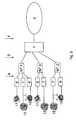
- the embodiment in Fig. :1shows a number of network terminators connected to an access network supporting multiple service providers.
- VLANsare used to separate traffic from different service providers and to separate traffic belonging to different services from a single service provider.
- a multitude of service providersare shown on the right side with SP 1 ... SP n.
- the service providersare connected to the core of the network 2 via the service provider access plane 5.
- the network core 2is connected via access plane 4 to a multitude of access multiplexers 1, such as a digital subscriber line access multiplexer or DSLAM (only one shown).
- the access multiplexer 1connects to a multitude of network terminators NT 1 ... N T m via an access plane 3.
- Access plane 3in practice represents e.g.
- the network terminatorconnects to home gateways, user devices and the like via subscriber plane 9, shown on the left side.
- Connectivity in subscriber plane 9, between network terminator and (user) devices etc.can e.g. be achieved by means of wired connections, such as twisted pair or coaxial cable, or wireless connections, such as wireless fidelity (WiFi), bluetooth or ultra wideband (UWB).
- WiFiwireless fidelity
- UWBultra wideband
- VLANsare used to facilitate communication between service providers and subscribers.
- VLANsare used to separate traffic from different service providers and to separate traffic belonging to different services from a specific service provider. This is indicated by the dotted arrows between the service providers SP 1 ... SP n and the access multiplexer 1.
- SP 1e.g. offers 3 services for transport to subscribers, indicated by VLAN 3, VLAN 755 and VLAN 1130.
- VLAN 3transports traffic belonging to a voice over IP service
- VLAN 755transports traffic belonging to an internet service
- VLAN 1130transports traffic belonging to an IP TV service.
- Fig. 2shows a number of network terminators NT 1 ... NT 3, that deliver multiple services 11 ... 13 to a numbers of subscribers.
- a different home gateway, residential gateway, settop box, vice over IP gateway or the likemay be employed. This is indicated by 6, 7 and 8, each representing a different type of home gateway.
- subscriber plane 9 communicationcan also be based on VLANs. In this case, translation of VLAN numbering between subscriber side and network side is performed by the network terminator.
- the service numbers on network side and subscriber side of the network terminator for a specific service relation between a subscriber and a service providerarc the same.
- untagged ethernetmay be used for communication in the subscriber plane 9.
- the network terminatorin that case translates untagged ethernet traffic from the subscriber plane to VLAN traffic on the network side with a specific service number reserved to indicate untagged ethernet traffic in the subscriber plane.
- the usage of the port number in the VLAN numberingis the same as in the case of translation to VLAN traffic in the subscriber plane, i.e. the port number on the network side corresponds with the physical port number on the subscriber side through which the traffic is delivered to the subscriber.
- Each service delivered to the subscribermay be originating from a different service provider.
- each home gatewayis connected to a different physical port on the subscriber side.
- two or more different services delivered to the subscribermay be originating from one service provider.
- two or more home gatewaysare connected to the same physical port on the subscriber side.
- the physical interface between the network terminator and the home gateway, settop box etc.can e.g. be ethernet, WiFi, Bluetooth and the like.
- the access multiplexer 1translates the VLAN numbers from the core network to VLAN numbers in the access plane 3. For each VLAN number from a specific service provider on the core network, a unique corresponding VLAN number in access plane 3 exists. This leads to the same total number of VLAN numbers in access plane 3 and the core network.
- This kind of VLAN number translation(indicated by T) is known to commonly skilled persons and need therefore not be explained in detail here.
- Fig. 3shows the relation between the physical ports of a network terminator and the virtual LAN numbering on the network side and the subscriber side.
- each physical port or port number on the subscriber side of the network terminatorhas a reflation to a specific port number in the VLAN numbering on the network side of the network terminator.
- the VLAN numbers(or VLAN tags) contain service numbers (port number set to zero).
- the service numbers for a specific physical port on the subscriber sideare the same as the service numbers combined with the corresponding port number in the VLAN numbering on the network side.
- the VLAN numbers(or tags) contain port numbers and service numbers.
Landscapes
- Engineering & Computer Science (AREA)
- Computer Networks & Wireless Communication (AREA)
- Signal Processing (AREA)
- Computer Security & Cryptography (AREA)
- Power Engineering (AREA)
- Small-Scale Networks (AREA)
- Mobile Radio Communication Systems (AREA)
- Data Exchanges In Wide-Area Networks (AREA)
- Transition And Organic Metals Composition Catalysts For Addition Polymerization (AREA)
Abstract
Description
- The invention relates to VLAN numbering in access networks.
- It is known that access networks based on e.g. DSL or fiber can be configured such by network providers, that subscribers are provided access to multiple service providers. In such a network configuration, all connected service providers are vice versa provided access to all connected subscribers.
US2004/0081180 discloses how a system maps network messages between a customer Virtual Local Area Network (VLAN) domain and a provider VLAN domain. Specifically, one or more ports of an intermediate network device include frame mapping logic and may further include a plurality of highly flexible, programmable mapping tables. In accordance with that invention, a received frame associated with a customer VLAN is mapped to a provider VLAN that is selected as a function of the frame's customer VLAN and the particular port on which the frame is received. The frame may also be mapped to a provider CoS value that is selected as a function of the frame's customer CoS value, customer VLAN and the port on which the frame is received. The provider VLAN designation and provider CoS value may be appended to the frame. Forwarding decisions within the provider domain are based, at least in part, on the frame's provider VLAN designation and provider CoS value.US2002/0141389 discloses a system and method for routing packets for IP telephony. The system includes an IP telephone (IPT) and a Service Gateway (SG) coupled via a network. The SG receives a data packet from the IPT, including a private source IP address (SIPA), source port number (SPN), and destination information for an IP device, performs network address persistent port translation (NAPPT) on the data packet, and sends it to the IP device. NAPPT changes the private SIA to a public SIA, leaving the SPN unchanged. The SG receives a data packet from the IP device, including a public destination IP address (DIPA, i.e., said public SIPA), a destination port number (DPN,i.e., said SPN), and source information, NAPPTs data packet, using the public DIPA and the DPN to identify the IPT, changing the public DIPA to the private SIPA, leaving the DPN unchanged, and sends the data packet to the IPT.US2006/0114915 a network device for implementing VLAN translation on a packet is disclosed. The network device includes a user network interface port for receiving and transmitting packets to customers of a network. The network device also includes a network to network interface port for communicating with a second network device in the network. A packet received at the user network interface port is classified, translated based on a predefined provider field associated with the packet, and encapsulated with a tag that is removed when the packet is transmitted from the user network interface port to a customer.- In known configurations for access networks with multiple service providers, configuration and management of a multitude of service providers needs to be performed per network terminator. I.e. for each subscriber the network terminator at the subscriber premises need to be configured to allow access to each specific service provider from the subscriber premises. And for each operational subscriber-service provider relation administration needs to be maintained in the network terminator.
- The aim of the invention is to reduce the configuration and management efforts needed in configurations for access networks with multiple service providers.
- The present invention is according to the independent claims, and provides a solution to reduce the configuration and management efforts needed for configuring access networks with multiple service providers. To this end, the current invention eliminates the need for configuring and managing the network terminator at the subscriber premises in order to allow the subscriber to access a service provider.
- According to an aspect of the invention, a network terminator connected to an access network supports virtual local area network (VLAN) numbering on both the network side and the subscriber side. The network terminator connects both VLANs. The VLAN numbering on the network side comprises both port numbers and service numbers.
- According to an embodiment of this aspect of the invention, the network terminator "strips" the port number from the VLAN numbering on the network side and delivers the services to the subscriber side through the physical port at subscriber side that corresponds with the stripped port number. In this direction towards the subscriber, the network terminator copies the VLAN numbers for the services delivered at the subscriber side from the corresponding VLAN service numbers at the network side.
- Vice versa, the network terminator "adds" a port number to the VLAN numbering from the subscriber side and delivers the services at the network side, with a port number in the VLAN numbering that corresponds with the physical port number at the subscriber side. In this direction towards the network the network terminator copies the service numbers from the subscriber side into the VLAN numbers on the network side. According to the invention "stripping" means setting the bits of the port number part from the VLAN ID (or VLAN tag) to zero.
- Vice versa, "adding" means setting the bits of the port number in the VLAN numbering on the network side to the value
that corresponds with the physical port number at the subscriber side. The number of bits on network side and subscriber side of the network terminator is constant, preferably 12 bits. - According to another aspect of the invention, the network terminator supports VLANs on the network side and untagged ethernet on the subscriber side of the device. The VLAN numbering on the network side has the same structure as explained above, but now one specific service number value is reserved to indicate a relation to untagged ethernet traffic on the subscriber side of the device, i.e. when this specific service number value is used, the device will translate this traffic from the VLAN on the network side to untagged ethernet traffic on the subscriber side, thereby stripping the VLAN tag entirely. According to the invention, for untagged ethernet traffic in the direction from subscriber to network (service provider), the network terminator adds aforementioned specific service number value in the VLAN numbering on the network side.
- According to an embodiment of this other aspect of the invention, the specific service number value to indicate a relation to untagged ethernet traffic on the subscriber side of the device is 1000 0000 (decimal 128) in the VLAN numbering on the network side of the device. In this case, all traffic that is to be transported using untagged ethernet in the subscriber plane, is coded by the service provider with the service number in the VLAN tag set to 1000 0000 (128 decimal). When this translation from VLAN traffic to ethernet traffic (and vice versa) is used, the usage of the port number in the VLAN numbering on the network side remains unchanged.
- According to another aspect of the invention, the network terminator supports a division of the service numbers in the VLAN numbering.
- According to yet another aspect of the invention, the service number blocks are used for traffic separation.
- According to another aspect of the invention, traffic separation is used to distinguish between different classes of service.
- According to another aspect of the invention, the device uses a different traffic queue for each class of service and each traffic queue is handled by the device with a different priority.
- According to another aspect of the invention, the traffic queues are implemented in the upstream, i.e. the direction from subscriber to the network.
- According to another aspect of the invention, the traffic queues are implemented in the downstream, i.e. the direction from network to subscriber.
- According to an embodiment of the invention, the VLAN numbering on the network side is such that port numbers in VLAN numbers to one specific network terminator have a constant value for services from one specific service provider. The VLAN numbering on the subscriber side comprises service numbers and all services from one specific service provider are delivered to the subscriber through one specific physical port on the subscriber side.
- The invention will be explained in greater detail by reference to exemplary embodiments shown in the drawings, in which:
Fig. 1 shows network terminators connected to a multiple service provider network supporting virtual LANs.Fig. 2 shows network terminators connected to a multi service provider network, wherein each network terminator is connected to a number of home gateways, residential gateways, settop boxes, voice over IP gateways and the like.Fig. 3 shows the relation between the physical ports of a network terminator and the virtual LAN numbering on the network side and the subscriber side.- For the purpose of teaching of the invention, preferred embodiments of a device according to the invention are described in the sequel. It will be apparent to the person skilled in the art that other alternative and equivalent embodiments of the invention can be conceived and reduced to practice, the scope of the invention being only limited by the claims as finally granted.
- The embodiment in
Fig. :1 shows a number of network terminators connected to an access network supporting multiple service providers. VLANs are used to separate traffic from different service providers and to separate traffic belonging to different services from a single service provider. A multitude of service providers are shown on the right side withSP 1 ... SP n. The service providers are connected to the core of thenetwork 2 via the serviceprovider access plane 5. In the direction of the subscribers, thenetwork core 2 is connected viaaccess plane 4 to a multitude ofaccess multiplexers 1, such as a digital subscriber line access multiplexer or DSLAM (only one shown). Theaccess multiplexer 1 connects to a multitude of network terminators NT 1 ... N T m via anaccess plane 3.Access plane 3 in practice represents e.g. twisted pair cable, optical fiber or coaxial cable. Finally, the network terminator connects to home gateways, user devices and the like viasubscriber plane 9, shown on the left side. Connectivity insubscriber plane 9, between network terminator and (user) devices etc. can e.g. be achieved by means of wired connections, such as twisted pair or coaxial cable, or wireless connections, such as wireless fidelity (WiFi), bluetooth or ultra wideband (UWB). - In the embodiment of
Fig. 1 , VLANs are used to facilitate communication between service providers and subscribers. In the core of the network VLANs are used to separate traffic from different service providers and to separate traffic belonging to different services from a specific service provider. This is indicated by the dotted arrows between theservice providers SP 1 ... SP n and theaccess multiplexer 1. In the embodiment shown inFig. 1 ,SP 1 e.g. offers 3 services for transport to subscribers, indicated byVLAN 3, VLAN 755 and VLAN 1130. For instance,VLAN 3 transports traffic belonging to a voice over IP service, VLAN 755 transports traffic belonging to an internet service and VLAN 1130 transports traffic belonging to an IP TV service. Mutatis mutandisSP 2 offers one service via 1 VLAN andSP 3 andSP n offer 2 services via 2 VLANs. This is further illustrated inFig. 2 , which shows a number of network terminators NT 1 ...NT 3, that delivermultiple services 11 ... 13 to a numbers of subscribers. For each different service, a different home gateway, residential gateway, settop box, vice over IP gateway or the like may be employed. This is indicated by 6, 7 and 8, each representing a different type of home gateway. Insubscriber plane 9 communication can also be based on VLANs. In this case, translation of VLAN numbering between subscriber side and network side is performed by the network terminator. In this case the service numbers on network side and subscriber side of the network terminator for a specific service relation between a subscriber and a service provider arc the same. This will be explained further below. However, also untagged ethernet may be used for communication in thesubscriber plane 9. Tn that case no VLAN tag is used in the subscriber plane. The network terminator in that case translates untagged ethernet traffic from the subscriber plane to VLAN traffic on the network side with a specific service number reserved to indicate untagged ethernet traffic in the subscriber plane. In this case the usage of the port number in the VLAN numbering is the same as in the case of translation to VLAN traffic in the subscriber plane, i.e. the port number on the network side corresponds with the physical port number on the subscriber side through which the traffic is delivered to the subscriber. - Each service delivered to the subscriber may be originating from a different service provider. In this case, according to the invention, each home gateway is connected to a different physical port on the subscriber side. On the other hand, two or more different services delivered to the subscriber may be originating from one service provider. In this case two or more home gateways are connected to the same physical port on the subscriber side.
- The physical interface between the network terminator and the home gateway, settop box etc. can e.g. be ethernet, WiFi, Bluetooth and the like.
- According to the embodiment in
Fig. 1 theaccess multiplexer 1 translates the VLAN numbers from the core network to VLAN numbers in theaccess plane 3. For each VLAN number from a specific service provider on the core network, a unique corresponding VLAN number inaccess plane 3 exists. This leads to the same total number of VLAN numbers inaccess plane 3 and the core network. This kind of VLAN number translation (indicated by T) is known to commonly skilled persons and need therefore not be explained in detail here. - The invention is further explained with the aid of
Fig. 3 , which shows the relation between the physical ports of a network terminator and the virtual LAN numbering on the network side and the subscriber side. - As shown in
Fig. 3 , each physical port or port number on the subscriber side of the network terminator has a reflation to a specific port number in the VLAN numbering on the network side of the network terminator. On the subscriber side, the VLAN numbers (or VLAN tags) contain service numbers (port number set to zero). The service numbers for a specific physical port on the subscriber side are the same as the service numbers combined with the corresponding port number in the VLAN numbering on the network side. On the network side the VLAN numbers (or tags) contain port numbers and service numbers.
Claims (5)
- Network terminating device (NT, NT1, ... m) adapted for use in an access network (2) supporting virtual local area networks, VLAN, on the network side and untagged Ethernet on the subscriber side for facilitating communication between service providers (SP1, ...n) and subscribers,
in the access network (2) different services from different service providers being delivered to a subscriber as traffic over the network (2), and the traffic being arranged for delivery through one or more ports (6, 7, 8), each with a physical port number, to the subscriber; and
the VLAN being arranged to separate traffic from different service providers and having a numbering thereto ; and
the VLAN numbering on the network side comprising port numbers and service numbers, the service numbers differentiating the different services of one or more of the service providers (SP1, ...n), the untagged Ethernet on the subscriber side being a translation of the VLAN numbering on the network side ;
characterized in that
the network terminating device (NT, NT1, ... m) is adapted for the translation of the VLAN numbering including means for removing the VLAN numbering in the direction from the network side to the subscriber side in case one specific service number is part of the VLAN numbering, and means for adding, in the direction from the subscriber side to the network side, a port number to the VLAN numbering at the network side;
while and thereby eliminating the need for monitoring each operational subscriber service provider relation administration in the network terminating device. - The network terminating device as recited in claim 1, wherein the specific service number corresponds to decimal 128.
- The network terminating device as recited in claim 1, in which the port numbers and service numbers have a binary format structure and wherein the specific service number 1000 0000 is reserved to indicate the relation to untagged Ethernet traffic on the subscriber side of the network terminating device.
- An access network (2) supporting virtual local area networks, VLAN, on the network side and untagged Ethernet on the subscriber side for facilitating communication between service providers (SP1,... n) and subscribers,
in the access network (2) different services from different service providers being delivered to a subscriber as traffic over the network (2), and the traffic being arranged for delivery through one or more ports (6, 7, 8), each with a physical port number on the subscriber side, to the subscriber; and
the VLAN being arranged to separate traffic from different service providers (SP1,... n) and having a numbering thereto ; and
the VLAN numbering on the network side comprising port numbers and service numbers, the service numbers differentiating the different services of one or more of the service providers (SP1,... n), the VLAN numbering on the network side being a translation of the VLAN numbering on the subscriber side ;
characterized in that
the access network (2) contains a network terminating device (NT, NT1,... m) adapted for the translation of the VLAN numbering including for removing the VLAN numbering in the direction from the network side to the subscriber side in case one specific service number is part of the VLAN numbering, and for adding, in the direction from the subscriber side to the network side, a port number to the VLAN numbering at the network side;
while and thereby eliminating the need for monitoring each operational subscriber service provider relation administration in the network terminating device. - A method for facilitating communication between service providers (SP1, ... n) and their subscribers in a multiple service provider access network (2), the access network supporting virtual local area networks, VLAN, on the network side and untagged Ethernet on the subscriber side, the method comprising the steps of :providing different services from different service providers (SP1, ... n) to a subscriber as traffic over the access network (2), and the traffic being delivered through one or more ports (6, 7, 8), each with a physical port number on the subscriber side, to the subscriber ; andseparating traffic from different service providers by using the virtual local area (VLAN) networks having a numbering thereto ; andproviding the VLAN numbering on the network side with port numbers and service numbers, the service numbers differentiating the different services of one or more of the service providers (SP1,... n), the VLAN numbering on the network side being a translation of the VLAN numbering on the subscriber sidecharacterized in that the method furthermore the step offor the translation of the VLAN numbering including removing the VLAN numbering in the direction from the network side to the subscriber side in case one specific service number is part of the VLAN numbering, and adding, in the direction from the subscriber side to the network side, a port number to the VLAN numbering at the network side;while and thereby eliminating the need for monitoring each operational subscriber service provider relation administration in the network terminating device.
Priority Applications (1)
| Application Number | Priority Date | Filing Date | Title |
|---|---|---|---|
| PL10174513TPL2293526T3 (en) | 2007-02-05 | 2007-02-05 | VLAN numbering in access networks |
Applications Claiming Priority (1)
| Application Number | Priority Date | Filing Date | Title |
|---|---|---|---|
| EP07002405AEP1954009B1 (en) | 2007-02-05 | 2007-02-05 | VLAN numbering in access networks |
Related Parent Applications (4)
| Application Number | Title | Priority Date | Filing Date |
|---|---|---|---|
| EP07002405ADivisionEP1954009B1 (en) | 2007-02-05 | 2007-02-05 | VLAN numbering in access networks |
| EP07002405APreviously-Filed-ApplicationEP1954009B1 (en) | 2007-02-05 | 2007-02-05 | VLAN numbering in access networks |
| EP07002405.4Division | 2007-02-05 | ||
| EP07002405Previously-Filed-Application | 2007-02-05 |
Publications (2)
| Publication Number | Publication Date |
|---|---|
| EP2293526A1 EP2293526A1 (en) | 2011-03-09 |
| EP2293526B1true EP2293526B1 (en) | 2015-04-08 |
Family
ID=37898335
Family Applications (2)
| Application Number | Title | Priority Date | Filing Date |
|---|---|---|---|
| EP10174513.1AActiveEP2293526B1 (en) | 2007-02-05 | 2007-02-05 | VLAN numbering in access networks |
| EP07002405AActiveEP1954009B1 (en) | 2007-02-05 | 2007-02-05 | VLAN numbering in access networks |
Family Applications After (1)
| Application Number | Title | Priority Date | Filing Date |
|---|---|---|---|
| EP07002405AActiveEP1954009B1 (en) | 2007-02-05 | 2007-02-05 | VLAN numbering in access networks |
Country Status (5)
| Country | Link |
|---|---|
| US (4) | US8340107B2 (en) |
| EP (2) | EP2293526B1 (en) |
| AT (1) | ATE536033T1 (en) |
| ES (2) | ES2377886T3 (en) |
| PL (2) | PL1954009T3 (en) |
Families Citing this family (5)
| Publication number | Priority date | Publication date | Assignee | Title |
|---|---|---|---|---|
| EP2293526B1 (en)* | 2007-02-05 | 2015-04-08 | Koninklijke KPN N.V. | VLAN numbering in access networks |
| CN103782550A (en)* | 2011-09-20 | 2014-05-07 | 汤姆逊许可公司 | Method and apparatus for null virtual local area network identification transformation |
| US9692732B2 (en)* | 2011-11-29 | 2017-06-27 | Amazon Technologies, Inc. | Network connection automation |
| US9426023B2 (en) | 2014-08-08 | 2016-08-23 | International Business Machines Corporation | Automatic reconfiguration of network parameters during file system failover |
| US11281993B2 (en) | 2016-12-05 | 2022-03-22 | Apple Inc. | Model and ensemble compression for metric learning |
Family Cites Families (36)
| Publication number | Priority date | Publication date | Assignee | Title |
|---|---|---|---|---|
| US6188694B1 (en)* | 1997-12-23 | 2001-02-13 | Cisco Technology, Inc. | Shared spanning tree protocol |
| US6252888B1 (en)* | 1998-04-14 | 2001-06-26 | Nortel Networks Corporation | Method and apparatus providing network communications between devices using frames with multiple formats |
| GB9824594D0 (en)* | 1998-11-11 | 1999-01-06 | 3Com Technologies Ltd | Modifying tag fields in ethernet data packets |
| US8266266B2 (en)* | 1998-12-08 | 2012-09-11 | Nomadix, Inc. | Systems and methods for providing dynamic network authorization, authentication and accounting |
| US6515990B1 (en)* | 1999-03-31 | 2003-02-04 | Advanced Micro Devices, Inc. | Dequeuing logic architecture and operation in a multiport communication switch |
| US6879588B1 (en)* | 1999-05-21 | 2005-04-12 | Broadcom Corporation | Address resolution snoop support for CPU |
| US6901452B1 (en)* | 2000-03-02 | 2005-05-31 | Alcatel | Selectable prioritization for data communication switch |
| EP1162796B1 (en)* | 2000-06-09 | 2012-08-15 | Broadcom Corporation | Cascading of gigabit switches |
| US7047314B2 (en)* | 2000-12-28 | 2006-05-16 | Oki Electric Industry Co., Ltd. | Duplicate private address translating system and duplicate address network system |
| US7068647B2 (en) | 2001-04-03 | 2006-06-27 | Voxpath Networks, Inc. | System and method for routing IP packets |
| US7272137B2 (en)* | 2001-05-14 | 2007-09-18 | Nortel Networks Limited | Data stream filtering apparatus and method |
| JP4236398B2 (en)* | 2001-08-15 | 2009-03-11 | 富士通株式会社 | Communication method, communication system, and communication connection program |
| WO2003067821A1 (en)* | 2002-02-08 | 2003-08-14 | Telefonaktiebolaget Lm Ericsson (Publ) | Method and system relating service providers to clients, in an access network, using dynamically allocated mac addresses |
| US6789121B2 (en)* | 2002-02-08 | 2004-09-07 | Nortel Networks Limited | Method of providing a virtual private network service through a shared network, and provider edge device for such network |
| US20030152075A1 (en)* | 2002-02-14 | 2003-08-14 | Hawthorne Austin J. | Virtual local area network identifier translation in a packet-based network |
| US8051211B2 (en)* | 2002-10-29 | 2011-11-01 | Cisco Technology, Inc. | Multi-bridge LAN aggregation |
| US7180899B2 (en) | 2002-10-29 | 2007-02-20 | Cisco Technology, Inc. | Multi-tiered Virtual Local area Network (VLAN) domain mapping mechanism |
| US7298705B2 (en)* | 2003-02-05 | 2007-11-20 | Broadcom Corporation | Fast-path implementation for a double tagging loopback engine |
| CN1277373C (en)* | 2003-05-07 | 2006-09-27 | 华为技术有限公司 | Method for transmitting user position information in network communication system |
| US6901072B1 (en)* | 2003-05-15 | 2005-05-31 | Foundry Networks, Inc. | System and method for high speed packet transmission implementing dual transmit and receive pipelines |
| US20050138149A1 (en)* | 2003-12-23 | 2005-06-23 | Jagjeet Bhatia | Method and system for increasing available user VLAN space |
| US7333508B2 (en)* | 2004-01-20 | 2008-02-19 | Nortel Networks Limited | Method and system for Ethernet and frame relay network interworking |
| US7391771B2 (en)* | 2004-01-23 | 2008-06-24 | Metro Packet Systems Inc. | Method of sending information through a tree and ring topology of a network system |
| WO2005086429A1 (en)* | 2004-02-27 | 2005-09-15 | Viadux, Inc. | System and method for dynamic vlan multiplexing |
| US7830892B2 (en) | 2004-11-30 | 2010-11-09 | Broadcom Corporation | VLAN translation in a network device |
| EP1703672B1 (en)* | 2005-03-17 | 2007-04-25 | Alcatel Lucent | Method for exchanging packets of user data |
| US9088669B2 (en)* | 2005-04-28 | 2015-07-21 | Cisco Technology, Inc. | Scalable system and method for DSL subscriber traffic over an Ethernet network |
| JP4738901B2 (en)* | 2005-06-07 | 2011-08-03 | 株式会社日立製作所 | VLANID dynamic allocation method and packet transfer apparatus |
| US8054842B2 (en)* | 2005-10-31 | 2011-11-08 | Alcatel Lucent | Apparatus for providing internet protocol television service and internet service |
| US7889738B2 (en)* | 2005-12-21 | 2011-02-15 | Solace Systems Inc. | Shared application inter-working with virtual private networks |
| US20080019385A1 (en)* | 2005-12-30 | 2008-01-24 | Huawei Technologies Co., Inc. (Usa) | System and method of mapping between local and global service instance identifiers in provider networks |
| CN100555949C (en)* | 2006-03-22 | 2009-10-28 | 华为技术有限公司 | A kind of to GPON system configuration Native VLAN and processing Ethernet method of message |
| US8085790B2 (en)* | 2006-07-14 | 2011-12-27 | Cisco Technology, Inc. | Ethernet layer 2 protocol packet switching |
| US7965716B2 (en)* | 2006-12-06 | 2011-06-21 | Telefonaktiebolaget L M Ericsson (Publ) | Extended VLAN classification |
| EP2293526B1 (en)* | 2007-02-05 | 2015-04-08 | Koninklijke KPN N.V. | VLAN numbering in access networks |
| US9160609B2 (en)* | 2010-05-28 | 2015-10-13 | Futurewei Technologies, Inc. | Virtual Layer 2 and mechanism to make it scalable |
- 2007
- 2007-02-05EPEP10174513.1Apatent/EP2293526B1/enactiveActive
- 2007-02-05ESES07002405Tpatent/ES2377886T3/enactiveActive
- 2007-02-05EPEP07002405Apatent/EP1954009B1/enactiveActive
- 2007-02-05PLPL07002405Tpatent/PL1954009T3/enunknown
- 2007-02-05ESES10174513.1Tpatent/ES2540466T3/enactiveActive
- 2007-02-05PLPL10174513Tpatent/PL2293526T3/enunknown
- 2007-02-05ATAT07002405Tpatent/ATE536033T1/enactive
- 2008
- 2008-02-04USUS12/012,605patent/US8340107B2/ennot_activeExpired - Fee Related
- 2012
- 2012-11-30USUS13/690,134patent/US8964768B2/enactiveActive
- 2012-11-30USUS13/690,679patent/US20130114608A1/ennot_activeAbandoned
- 2012-11-30USUS13/690,972patent/US20130114609A1/ennot_activeAbandoned
Also Published As
| Publication number | Publication date |
|---|---|
| US8964768B2 (en) | 2015-02-24 |
| US20130114609A1 (en) | 2013-05-09 |
| US20130089108A1 (en) | 2013-04-11 |
| PL2293526T3 (en) | 2015-08-31 |
| EP1954009A1 (en) | 2008-08-06 |
| EP2293526A1 (en) | 2011-03-09 |
| US20080186980A1 (en) | 2008-08-07 |
| ES2377886T3 (en) | 2012-04-02 |
| ES2540466T3 (en) | 2015-07-09 |
| EP1954009B1 (en) | 2011-11-30 |
| PL1954009T3 (en) | 2012-04-30 |
| US8340107B2 (en) | 2012-12-25 |
| ATE536033T1 (en) | 2011-12-15 |
| US20130114608A1 (en) | 2013-05-09 |
Similar Documents
| Publication | Publication Date | Title |
|---|---|---|
| US8144699B2 (en) | Auto-provisioning of network services over an ethernet access link | |
| AU2003243064B2 (en) | An arrangement and a method relating to ethernet access systems | |
| US7835370B2 (en) | System and method for DSL subscriber identification over ethernet network | |
| US8249082B2 (en) | System method for a communications access network | |
| US8913623B2 (en) | Method and apparatus for processing labeled flows in a communications access network | |
| CN101150493B (en) | A method and system for distributing service at access terminal | |
| US8014316B2 (en) | System, method and computer-readable storage medium for calculating addressing and bandwidth requirements of a network | |
| JP4819956B2 (en) | Apparatus and method in switched telecommunications system | |
| EP4092973A1 (en) | Point-to-multipoint functionality in a bridged network | |
| EP2293526B1 (en) | VLAN numbering in access networks | |
| AU767345B2 (en) | A device and a method in a switched telecommunication system | |
| KR20060059877A (en) | Apparatus and method for Ethernet access system | |
| EP2071766B1 (en) | System and method for improved traffic aggregation in an access network | |
| US20070121628A1 (en) | System and method for source specific multicast | |
| EP2007079A1 (en) | Method and device for routing data traffic and communication system comprising such device |
Legal Events
| Date | Code | Title | Description |
|---|---|---|---|
| PUAI | Public reference made under article 153(3) epc to a published international application that has entered the european phase | Free format text:ORIGINAL CODE: 0009012 | |
| AC | Divisional application: reference to earlier application | Ref document number:1954009 Country of ref document:EP Kind code of ref document:P | |
| AK | Designated contracting states | Kind code of ref document:A1 Designated state(s):AT BE BG CH CY CZ DE DK EE ES FI FR GB GR HU IE IS IT LI LT LU LV MC NL PL PT RO SE SI SK TR | |
| 17P | Request for examination filed | Effective date:20110909 | |
| 17Q | First examination report despatched | Effective date:20120706 | |
| RIC1 | Information provided on ipc code assigned before grant | Ipc:H04L 12/46 20060101ALN20141205BHEP Ipc:H04L 12/24 20060101ALI20141205BHEP Ipc:H04L 29/12 20060101AFI20141205BHEP Ipc:H04L 12/931 20130101ALI20141205BHEP | |
| GRAP | Despatch of communication of intention to grant a patent | Free format text:ORIGINAL CODE: EPIDOSNIGR1 | |
| INTG | Intention to grant announced | Effective date:20150116 | |
| RIN1 | Information on inventor provided before grant (corrected) | Inventor name:VINOD, LUTHRA Inventor name:DE BOER, ALEXANDER PETER | |
| GRAS | Grant fee paid | Free format text:ORIGINAL CODE: EPIDOSNIGR3 | |
| GRAA | (expected) grant | Free format text:ORIGINAL CODE: 0009210 | |
| AC | Divisional application: reference to earlier application | Ref document number:1954009 Country of ref document:EP Kind code of ref document:P | |
| AK | Designated contracting states | Kind code of ref document:B1 Designated state(s):AT BE BG CH CY CZ DE DK EE ES FI FR GB GR HU IE IS IT LI LT LU LV MC NL PL PT RO SE SI SK TR | |
| REG | Reference to a national code | Ref country code:GB Ref legal event code:FG4D | |
| RIN1 | Information on inventor provided before grant (corrected) | Inventor name:VINOD, LUTHRA Inventor name:DE BOER, ALEXANDER PETER | |
| REG | Reference to a national code | Ref country code:CH Ref legal event code:EP | |
| REG | Reference to a national code | Ref country code:IE Ref legal event code:FG4D | |
| REG | Reference to a national code | Ref country code:AT Ref legal event code:REF Ref document number:721307 Country of ref document:AT Kind code of ref document:T Effective date:20150515 | |
| REG | Reference to a national code | Ref country code:DE Ref legal event code:R096 Ref document number:602007041017 Country of ref document:DE Effective date:20150521 | |
| REG | Reference to a national code | Ref country code:ES Ref legal event code:FG2A Ref document number:2540466 Country of ref document:ES Kind code of ref document:T3 Effective date:20150709 | |
| REG | Reference to a national code | Ref country code:NL Ref legal event code:T3 | |
| REG | Reference to a national code | Ref country code:SE Ref legal event code:TRGR | |
| REG | Reference to a national code | Ref country code:NL Ref legal event code:T3 | |
| REG | Reference to a national code | Ref country code:AT Ref legal event code:MK05 Ref document number:721307 Country of ref document:AT Kind code of ref document:T Effective date:20150408 | |
| REG | Reference to a national code | Ref country code:PL Ref legal event code:T3 | |
| REG | Reference to a national code | Ref country code:LT Ref legal event code:MG4D | |
| PG25 | Lapsed in a contracting state [announced via postgrant information from national office to epo] | Ref country code:LT Free format text:LAPSE BECAUSE OF FAILURE TO SUBMIT A TRANSLATION OF THE DESCRIPTION OR TO PAY THE FEE WITHIN THE PRESCRIBED TIME-LIMIT Effective date:20150408 Ref country code:PT Free format text:LAPSE BECAUSE OF FAILURE TO SUBMIT A TRANSLATION OF THE DESCRIPTION OR TO PAY THE FEE WITHIN THE PRESCRIBED TIME-LIMIT Effective date:20150810 Ref country code:FI Free format text:LAPSE BECAUSE OF FAILURE TO SUBMIT A TRANSLATION OF THE DESCRIPTION OR TO PAY THE FEE WITHIN THE PRESCRIBED TIME-LIMIT Effective date:20150408 | |
| PG25 | Lapsed in a contracting state [announced via postgrant information from national office to epo] | Ref country code:GR Free format text:LAPSE BECAUSE OF FAILURE TO SUBMIT A TRANSLATION OF THE DESCRIPTION OR TO PAY THE FEE WITHIN THE PRESCRIBED TIME-LIMIT Effective date:20150709 Ref country code:LV Free format text:LAPSE BECAUSE OF FAILURE TO SUBMIT A TRANSLATION OF THE DESCRIPTION OR TO PAY THE FEE WITHIN THE PRESCRIBED TIME-LIMIT Effective date:20150408 Ref country code:IS Free format text:LAPSE BECAUSE OF FAILURE TO SUBMIT A TRANSLATION OF THE DESCRIPTION OR TO PAY THE FEE WITHIN THE PRESCRIBED TIME-LIMIT Effective date:20150808 Ref country code:AT Free format text:LAPSE BECAUSE OF FAILURE TO SUBMIT A TRANSLATION OF THE DESCRIPTION OR TO PAY THE FEE WITHIN THE PRESCRIBED TIME-LIMIT Effective date:20150408 | |
| REG | Reference to a national code | Ref country code:DE Ref legal event code:R097 Ref document number:602007041017 Country of ref document:DE | |
| PG25 | Lapsed in a contracting state [announced via postgrant information from national office to epo] | Ref country code:EE Free format text:LAPSE BECAUSE OF FAILURE TO SUBMIT A TRANSLATION OF THE DESCRIPTION OR TO PAY THE FEE WITHIN THE PRESCRIBED TIME-LIMIT Effective date:20150408 Ref country code:DK Free format text:LAPSE BECAUSE OF FAILURE TO SUBMIT A TRANSLATION OF THE DESCRIPTION OR TO PAY THE FEE WITHIN THE PRESCRIBED TIME-LIMIT Effective date:20150408 | |
| PLBE | No opposition filed within time limit | Free format text:ORIGINAL CODE: 0009261 | |
| STAA | Information on the status of an ep patent application or granted ep patent | Free format text:STATUS: NO OPPOSITION FILED WITHIN TIME LIMIT | |
| REG | Reference to a national code | Ref country code:FR Ref legal event code:PLFP Year of fee payment:10 | |
| PG25 | Lapsed in a contracting state [announced via postgrant information from national office to epo] | Ref country code:CZ Free format text:LAPSE BECAUSE OF FAILURE TO SUBMIT A TRANSLATION OF THE DESCRIPTION OR TO PAY THE FEE WITHIN THE PRESCRIBED TIME-LIMIT Effective date:20150408 Ref country code:SK Free format text:LAPSE BECAUSE OF FAILURE TO SUBMIT A TRANSLATION OF THE DESCRIPTION OR TO PAY THE FEE WITHIN THE PRESCRIBED TIME-LIMIT Effective date:20150408 Ref country code:RO Free format text:LAPSE BECAUSE OF NON-PAYMENT OF DUE FEES Effective date:20150408 | |
| 26N | No opposition filed | Effective date:20160111 | |
| PG25 | Lapsed in a contracting state [announced via postgrant information from national office to epo] | Ref country code:SI Free format text:LAPSE BECAUSE OF FAILURE TO SUBMIT A TRANSLATION OF THE DESCRIPTION OR TO PAY THE FEE WITHIN THE PRESCRIBED TIME-LIMIT Effective date:20150408 | |
| PG25 | Lapsed in a contracting state [announced via postgrant information from national office to epo] | Ref country code:MC Free format text:LAPSE BECAUSE OF FAILURE TO SUBMIT A TRANSLATION OF THE DESCRIPTION OR TO PAY THE FEE WITHIN THE PRESCRIBED TIME-LIMIT Effective date:20150408 Ref country code:LU Free format text:LAPSE BECAUSE OF FAILURE TO SUBMIT A TRANSLATION OF THE DESCRIPTION OR TO PAY THE FEE WITHIN THE PRESCRIBED TIME-LIMIT Effective date:20160205 | |
| REG | Reference to a national code | Ref country code:CH Ref legal event code:PL | |
| PG25 | Lapsed in a contracting state [announced via postgrant information from national office to epo] | Ref country code:CH Free format text:LAPSE BECAUSE OF NON-PAYMENT OF DUE FEES Effective date:20160229 Ref country code:LI Free format text:LAPSE BECAUSE OF NON-PAYMENT OF DUE FEES Effective date:20160229 | |
| REG | Reference to a national code | Ref country code:IE Ref legal event code:MM4A | |
| PG25 | Lapsed in a contracting state [announced via postgrant information from national office to epo] | Ref country code:IE Free format text:LAPSE BECAUSE OF NON-PAYMENT OF DUE FEES Effective date:20160205 | |
| REG | Reference to a national code | Ref country code:FR Ref legal event code:PLFP Year of fee payment:11 | |
| REG | Reference to a national code | Ref country code:FR Ref legal event code:PLFP Year of fee payment:12 | |
| PG25 | Lapsed in a contracting state [announced via postgrant information from national office to epo] | Ref country code:HU Free format text:LAPSE BECAUSE OF FAILURE TO SUBMIT A TRANSLATION OF THE DESCRIPTION OR TO PAY THE FEE WITHIN THE PRESCRIBED TIME-LIMIT; INVALID AB INITIO Effective date:20070205 Ref country code:CY Free format text:LAPSE BECAUSE OF FAILURE TO SUBMIT A TRANSLATION OF THE DESCRIPTION OR TO PAY THE FEE WITHIN THE PRESCRIBED TIME-LIMIT Effective date:20150408 | |
| PG25 | Lapsed in a contracting state [announced via postgrant information from national office to epo] | Ref country code:BG Free format text:LAPSE BECAUSE OF FAILURE TO SUBMIT A TRANSLATION OF THE DESCRIPTION OR TO PAY THE FEE WITHIN THE PRESCRIBED TIME-LIMIT Effective date:20150408 | |
| PGFP | Annual fee paid to national office [announced via postgrant information from national office to epo] | Ref country code:SE Payment date:20200220 Year of fee payment:14 Ref country code:PL Payment date:20200122 Year of fee payment:14 Ref country code:ES Payment date:20200322 Year of fee payment:14 Ref country code:IT Payment date:20200225 Year of fee payment:14 | |
| PGFP | Annual fee paid to national office [announced via postgrant information from national office to epo] | Ref country code:BE Payment date:20200219 Year of fee payment:14 | |
| PGFP | Annual fee paid to national office [announced via postgrant information from national office to epo] | Ref country code:TR Payment date:20200205 Year of fee payment:14 | |
| REG | Reference to a national code | Ref country code:SE Ref legal event code:EUG | |
| REG | Reference to a national code | Ref country code:BE Ref legal event code:MM Effective date:20210228 | |
| REG | Reference to a national code | Ref country code:DE Ref legal event code:R079 Ref document number:602007041017 Country of ref document:DE Free format text:PREVIOUS MAIN CLASS: H04L0029120000 Ipc:H04L0067286900 | |
| PG25 | Lapsed in a contracting state [announced via postgrant information from national office to epo] | Ref country code:SE Free format text:LAPSE BECAUSE OF NON-PAYMENT OF DUE FEES Effective date:20210206 | |
| PG25 | Lapsed in a contracting state [announced via postgrant information from national office to epo] | Ref country code:IT Free format text:LAPSE BECAUSE OF NON-PAYMENT OF DUE FEES Effective date:20210205 | |
| REG | Reference to a national code | Ref country code:ES Ref legal event code:FD2A Effective date:20220504 | |
| PG25 | Lapsed in a contracting state [announced via postgrant information from national office to epo] | Ref country code:ES Free format text:LAPSE BECAUSE OF NON-PAYMENT OF DUE FEES Effective date:20210206 Ref country code:BE Free format text:LAPSE BECAUSE OF NON-PAYMENT OF DUE FEES Effective date:20210228 | |
| P01 | Opt-out of the competence of the unified patent court (upc) registered | Effective date:20230517 | |
| PG25 | Lapsed in a contracting state [announced via postgrant information from national office to epo] | Ref country code:PL Free format text:LAPSE BECAUSE OF NON-PAYMENT OF DUE FEES Effective date:20210205 | |
| PG25 | Lapsed in a contracting state [announced via postgrant information from national office to epo] | Ref country code:TR Free format text:LAPSE BECAUSE OF NON-PAYMENT OF DUE FEES Effective date:20210205 | |
| PGFP | Annual fee paid to national office [announced via postgrant information from national office to epo] | Ref country code:NL Payment date:20250218 Year of fee payment:19 | |
| PGFP | Annual fee paid to national office [announced via postgrant information from national office to epo] | Ref country code:DE Payment date:20250218 Year of fee payment:19 | |
| PGFP | Annual fee paid to national office [announced via postgrant information from national office to epo] | Ref country code:FR Payment date:20250221 Year of fee payment:19 | |
| PGFP | Annual fee paid to national office [announced via postgrant information from national office to epo] | Ref country code:GB Payment date:20250219 Year of fee payment:19 |