EP2290401B1 - Ultra-stable short pulse remote sensor - Google Patents
Ultra-stable short pulse remote sensorDownload PDFInfo
- Publication number
- EP2290401B1 EP2290401B1EP10166934.9AEP10166934AEP2290401B1EP 2290401 B1EP2290401 B1EP 2290401B1EP 10166934 AEP10166934 AEP 10166934AEP 2290401 B1EP2290401 B1EP 2290401B1
- Authority
- EP
- European Patent Office
- Prior art keywords
- pulses
- pulse
- target
- scattered
- radiation
- Prior art date
- Legal status (The legal status is an assumption and is not a legal conclusion. Google has not performed a legal analysis and makes no representation as to the accuracy of the status listed.)
- Not-in-force
Links
- 230000005855radiationEffects0.000claimsdescription49
- 230000001427coherent effectEffects0.000claimsdescription21
- 238000000034methodMethods0.000claimsdescription15
- 230000003595spectral effectEffects0.000claimsdescription9
- 230000010287polarizationEffects0.000claimsdescription7
- 238000007493shaping processMethods0.000claimsdescription6
- 230000003111delayed effectEffects0.000claimsdescription5
- 230000002452interceptive effectEffects0.000claimsdescription3
- 230000002123temporal effectEffects0.000description14
- 230000003287optical effectEffects0.000description10
- 238000001514detection methodMethods0.000description9
- 238000001228spectrumMethods0.000description9
- 230000006870functionEffects0.000description6
- 239000000523sampleSubstances0.000description6
- 230000007774longtermEffects0.000description4
- 230000008569processEffects0.000description4
- 230000006641stabilisationEffects0.000description4
- 238000011105stabilizationMethods0.000description4
- 238000012512characterization methodMethods0.000description3
- 239000000463materialSubstances0.000description3
- 230000003321amplificationEffects0.000description2
- 230000008901benefitEffects0.000description2
- 230000001419dependent effectEffects0.000description2
- 238000005305interferometryMethods0.000description2
- 238000003199nucleic acid amplification methodMethods0.000description2
- 230000000087stabilizing effectEffects0.000description2
- 230000003044adaptive effectEffects0.000description1
- 238000004458analytical methodMethods0.000description1
- 238000010009beatingMethods0.000description1
- 239000002131composite materialSubstances0.000description1
- 238000006073displacement reactionMethods0.000description1
- 230000000694effectsEffects0.000description1
- 230000005684electric fieldEffects0.000description1
- 238000005516engineering processMethods0.000description1
- 230000007613environmental effectEffects0.000description1
- 239000000835fiberSubstances0.000description1
- 238000003384imaging methodMethods0.000description1
- 230000003993interactionEffects0.000description1
- 239000004973liquid crystal related substanceSubstances0.000description1
- 238000005259measurementMethods0.000description1
- 230000007246mechanismEffects0.000description1
- 230000004048modificationEffects0.000description1
- 238000012986modificationMethods0.000description1
- 239000004038photonic crystalSubstances0.000description1
- 238000012545processingMethods0.000description1
- 238000011084recoveryMethods0.000description1
- 230000004044responseEffects0.000description1
- 239000000126substanceSubstances0.000description1
- 238000012731temporal analysisMethods0.000description1
- 238000012795verificationMethods0.000description1
Images


Classifications
- G—PHYSICS
- G01—MEASURING; TESTING
- G01S—RADIO DIRECTION-FINDING; RADIO NAVIGATION; DETERMINING DISTANCE OR VELOCITY BY USE OF RADIO WAVES; LOCATING OR PRESENCE-DETECTING BY USE OF THE REFLECTION OR RERADIATION OF RADIO WAVES; ANALOGOUS ARRANGEMENTS USING OTHER WAVES
- G01S17/00—Systems using the reflection or reradiation of electromagnetic waves other than radio waves, e.g. lidar systems
- G01S17/02—Systems using the reflection of electromagnetic waves other than radio waves
- G01S17/06—Systems determining position data of a target
- G01S17/08—Systems determining position data of a target for measuring distance only
- G01S17/10—Systems determining position data of a target for measuring distance only using transmission of interrupted, pulse-modulated waves
- G—PHYSICS
- G01—MEASURING; TESTING
- G01S—RADIO DIRECTION-FINDING; RADIO NAVIGATION; DETERMINING DISTANCE OR VELOCITY BY USE OF RADIO WAVES; LOCATING OR PRESENCE-DETECTING BY USE OF THE REFLECTION OR RERADIATION OF RADIO WAVES; ANALOGOUS ARRANGEMENTS USING OTHER WAVES
- G01S7/00—Details of systems according to groups G01S13/00, G01S15/00, G01S17/00
- G01S7/48—Details of systems according to groups G01S13/00, G01S15/00, G01S17/00 of systems according to group G01S17/00
- G01S7/4802—Details of systems according to groups G01S13/00, G01S15/00, G01S17/00 of systems according to group G01S17/00 using analysis of echo signal for target characterisation; Target signature; Target cross-section
- G—PHYSICS
- G01—MEASURING; TESTING
- G01S—RADIO DIRECTION-FINDING; RADIO NAVIGATION; DETERMINING DISTANCE OR VELOCITY BY USE OF RADIO WAVES; LOCATING OR PRESENCE-DETECTING BY USE OF THE REFLECTION OR RERADIATION OF RADIO WAVES; ANALOGOUS ARRANGEMENTS USING OTHER WAVES
- G01S7/00—Details of systems according to groups G01S13/00, G01S15/00, G01S17/00
- G01S7/48—Details of systems according to groups G01S13/00, G01S15/00, G01S17/00 of systems according to group G01S17/00
- G01S7/483—Details of pulse systems
- G01S7/484—Transmitters
Definitions
- Conventional pulsed laser remote sensorsperform over short distances on the order of 1 km or less. Further, they typically require high power and implement incoherent direct detection methods. In contrast, conventional coherent pulsed laser sensors interfere a scattered pulse reflected from a target with a portion of the emitted pulse which was transmitted by the laser at an earlier time. A laser having extremely narrow frequency linewidths and a coherence length of at least twice as long as the operating range of the sensor must be used to ensure interference of the scattered pulse and the emitted pulse.
- a low power coherent pulsed laser remote sensor having a long coherence timeis desired in order to sense targets at long ranges. Further, it is desired that the laser sensor utilize amplitude and phase information contained in radiation pulses scattered by the targets to determine unique target signatures.
- US 2008/140341 A1discloses methods and apparatus for three-dimensional imaging of a sample.
- a sourceis provided of a beam of substantially collimated light characterized by a temporally dependent spectrum.
- the beamis focused in a plane characterized by a fixed displacement along the propagation axis of the beam, and scattered light from the sample is superposed with a reference beam derived from the substantially collimated source onto a focal plane detector array to provide an interference signal.
- a forward scattering modelis derived relating measured data to structure of an object to allow solution of an inverse scattering problem based upon the interference signal so that a three-dimensional structure of the sample may be inferred in near real time.
- US 2005/185188 A1discloses quantum resonance fluorescent microscope systems for detecting component substances in a specimen.
- the systemsare based on exciting the sample containing the material with a femtosecond to nanosecond probe pulse of collimated light, which is tailored to optimize detection of a given material by separating the probe pulse into component features of frequency, polarization, phase and/or amplitude.
- the component featuresare independently shaped and formed into a composite pulse selected to optimize a signature response pulse received from the material.
- two independently re-shaped pulsesare combined, where one re-shaped pulse has two mixed polarization states and the other re-shaped pulse is linearly polarized. These two pulses are made to intersect at an angle of 90 degrees so that the combined pulse has electric field in each of the XYZ axes.
- WO 2010/010437 A1discloses a Fourier transform spectrometer comprising: a coherent light source; an interferometer adapted to separate the coherent light source into two or more parts in order to generate through frequency- or phase-induced effects, interferences between the two or more parts; detection means adapted to detect the interferences, wherein the coherent light source comprises a frequency comb generator having a frequency repetition rate, and the detection means are adapted to detect the beating of pairs of frequencies of the frequency comb separated by the frequency repetition rate or a multiple of the frequency repetition rate.
- an ultra-stable short pulse remote sensorhaving extended temporal coherence for long range environmental sensing, surveillance, and reconnaissance.
- the sensordetermines unique target signatures after an ultrashort pulse has interacted with a target at range by measuring the spectral amplitude and phase of the scattered pulse.
- the ultra-stable short pulse remote sensorimproves over conventional optical remote sensors by achieving coherent detection of targets with reduced power and at long range, e.g., megameter ranges.
- the ultra-stable short pulse sensorcan be implemented in a small and lightweight system using commercially available technology.
- a receiveris configured to detect ultrashort multispectral pulses of radiation scattered by a target, the receiver comprising a detector configured to detect scattered radiation pulses produced by scattering of emitted radiation pulses by the target; an interferometer configured to interfere the scattered pulses with a reference pulse, wherein the emitted pulses and the reference pulse are different radiation pulses in a series of pulses; and a processor configured to determine an intensity and a phase of the scattered pulses based on the interference of the scattered pulses with the reference pulse.
- a method of detecting ultrashort multispectral pulses of radiation scattered by a targetincludes generating a series of coherent radiation pulses; selecting reference radiation pulses from the series of pulses; emitting radiation pulses from the series of pulses, wherein the reference pulses and the emitted pulses are different pulses; receiving scattered radiation pulses produced by scattering of the emitted pulses by the target; interfering the scattered pulses with the reference pulses; and determining an intensity and a phase of the scattered pulses based on the interference.
- a systemconfigured to emit and receive ultrashort multispectral pulses of radiation, the system comprising a source configured to generate a series of radiation pulses including reference radiation pulses and emitted radiation pulses produced by scattering of the emitted radiation pulses by a target; a receiver configured to receive scattered radiation pulses produced by scattering of the emitted radiation pulses by a target; an interferometer configured to interfere the scattered pulses with reference pulses; and a processor configured to determine an intensity and a phase of the scattered pulses based on an output of the interferometer.
- FIG. 1shows an exemplary ultrafast laser transceiver 100 with extended temporal coherence.
- Transceiver 100comprises temporally stabilized laser source 105 and receiver 110.
- Source 105emits a radiation beam comprising a train of ultrafast source pulses at a well defined repetition frequency.
- the pulses emitted from source 105are split into a beam of high-energy pulses 115 and a beam of low-energy reference pulses 120.
- High-energy pulses 115are launched toward target 125 and interact with target 125.
- Scattered radiation pulses 130are reflected back to receiver 110 due to scattering of high-energy pulses 115 by target 125.
- Low-energy reference pulses 120are coupled directly from source 105 to receiver 110.
- Receiver 110coherently combines low-energy pulses 120 and scattered pulses 130 to produce a signal for output or further processing.
- the optical information contained in scattered pulses 130may be measured by determining the differences between scattered pulses 130 and low-energy reference pulses 120.
- Such analysis of scattered pulses 130permits, e.g., discovery, detection, recognition, and/or verification of target 125.
- the range of transceiver 100may be limited due to instability of reference pulses 120 with respect to time, and the greater time-of-flight required for pulses 115 and 130 to reach more distant targets 125.
- FIG. 2shows exemplary pulse trains 200 for the beam of high-energy pulses 115 and the beam of low-energy reference pulses 120. While the sensor is not limited to single pulse detection, the discussion of the sensor operation may address two representative pulses for ease of understanding.
- scattered pulses 130comprises pulse n 0 205 which has been time delayed relative to reference pulses 120. The time delay results due to the time-of-flight required for pulses 115 and 130 to reflect from target 125.
- Pulse n 0 205is caused to interfere with pulse n 0 +n 210, which may be sampled directly from laser source 105 and provided by reference beam 120.
- nis a large number of pulses emitted from source 105 during the time delay of pulse n 0 205, e.g., tens, hundreds, thousands, or millions of pulses.
- a conventional delay lineis not required.
- Conventional delay lineswere necessary in previous devices due to the short coherence time of conventional laser sources which caused radiation pulses to lose coherency with subsequent pulses emitted after the coherence time. Therefore, without a conventional delay line, the coherency between a scattered pulse and a subsequent (i.e., reference) pulse would be lost by the time the scattered pulse returned from the target.
- conventional delay lineswere provided to enable both scattered pulses 130 and the reference pulse 120 from the same source pulse 105 to be interfered. Accordingly, it was necessary to match the delay of the conventional delay line to the time-of-flight for a pulse to reach the target and to return from the target.
- scattered pulse n 0 205can be interfered, e.g., with subsequent reference pulse n 0 +n 210, since reference pulses 120 remain coherent for an extended period of time.
- Figure 3shows the detecting of frequency information associated with scattered pulses 130 by non-linearly mixing scattered pulses 130 and reference pulses 120.
- interferograms 305 and 310may be produced by interference between pulse n 0 205 and pulse n 0 +n 210 and contains the optical information of pulse n 0 205.
- pulse n 0 205In order to produce a reliable signal, pulse n 0 205 must be coherent with pulse n 0 +n 210, such that the interferogram 310 is modulated with a wavelength dependant fringe pattern 315.
- pulse n 0 205 and pulse n 0 +n 210are not coherent, e.g., as in a free-running oscillator, no fringe pattern is observed, as shown by interferogram 305. Furthermore, it is not possible to detect and compensate for instantaneous intensity fluctuations in source 105. Therefore, intensity I(t) and phase ⁇ (t) information cannot be determined.
- the length of time that pulse n 0 205 can be coherently maintained with respect to pulse n 0 +n 210limits the range to which transceiver 100 can detect target 125.
- conventional ultrafast laserswhich operate with high repetition rates in excess of tens of MHz have short temporal coherence.
- source 105may have long term temporal stability in excess of 100 seconds. Further, such long term temporal stability enables interferogram 310 to use a multi-pulse exposure to improve the signal-to-noise ratio. For example, a one second exposure (i.e., only 1% of temporal coherence of source 105) allows interferogram 310 to be constructed from over a million pulses.
- Figures 4 and 5show alternative conventional characterizations of reference pulse 120.
- Figure 4shows the intensity of reference pulse 120 as a function of delay and wavelength.
- Figure 5shows the intensity and phase of reference pulse 120 as a function of delay.
- Figure 6shows the spectrum of exemplary interferogram 310 (see Figure 3 ) produced by the interference of reference pulse 120 with scattered pulses 130.
- fringes 315indicate the interference between reference pulse 120 with scattered pulses 130 caused by coherence between the pulses.
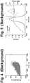
- Figure 7shows an exemplary pulse spectrograph of a scattered pulse corresponding to a first target, i.e. a first mirror.
- Figure 8shows an exemplary pulse spectrograph of a scattered pulse corresponding to a second target, i.e. a second mirror.
- each mirrorinteracts with the reference pulse in an unique manner, thus producing distinct signatures corresponding to a respective mirror.
- Ultra-stable pulse laser (USPL) 905generates a pulse train of ultrashort laser pulses having a wavelength, e.g. between 400 nm and 10,000 nm.
- the pulse traincan have a repetition rate on the order of 0.1 to 10 GHz, and the duration of each pulse can be on the order of several femtoseconds.
- laser 905is capable of extended temporal coherence such that the pulses in the pulse train are coherent with one another for an extended time period.
- Ultra-wideband (UWB) source 910converts the pulses produced by laser 905 to a supercontinuum of pulses having broad multispectral bandwidth, e.g. up to 500 THz.
- the pulsesare characterized by non-linear (NL) detector 915 either before or after being provided to UWB source 910.
- An exemplary reference pulse 120is shown having an intensity and phase which is representative of each of the other pulses in the pulse train.
- Pulse shaping encoder (PS-E) 920shapes the pulses for performance, e.g. in a military environment, and may have adaptive capabilities.
- PS-E 920can be configured as a liquid crystal spatial light modulator to adjust amplitude and phase of the individual spectral components.
- the pulsesreflect from target 125 and pulse shaping decoder (PS-D) 925 recovers scattered pulses 130 from the signal received from target 125.
- the intensity and phase of an exemplary scattered pulses 130are shown.
- Receiver 110interferes reference pulse 120 with scattered pulses 130 in order to recover the signature of target 125.
- Fig. 10shows laser source 105 according to an embodiment which comprises two stabilizing mechanisms.
- Source 105comprises ultrashort pulsed or "ultrafast" laser (USPL) 905 with both repetition rate and carrier-envelop offset (CEO) stabilizations.
- USPLultrashort pulsed or "ultrafast" laser
- CEOcarrier-envelop offset
- One requirement of laser 905comes from the CEO stabilization, which generally benefits from an octave of spectral width. This octave of spectral width can either be inherently designed into the laser or can be created through a process such as supercontinuum generation.
- Supercontinuum generationis a nonlinear phenomenon where the interaction of an ultrafast laser with, but not limited to, photonic crystal fiber (PCF) broadens the fundamental laser spectrum into a UWBW laser spectrum. If supercontinuum generation is used to meet the CEO stabilization criteria, the laser spectrum can be configured to be above 0.2 ⁇ m and below 2 ⁇ m.
- the repetition rate of laser 905may be fixed relative to an ultra-stable RF source.
- a fixed laser repetition rateresults from stabilizing the cavity length.
- the cavity lengthmay be stabilized via a feedback process using phase-locked loop (PLL) 1005.
- PLL 1005detects a small portion of the output of laser 905 by fast photodiode 1010 (rise time ⁇ 1 ns).
- PLL 1005compares the cavity repetition frequency with that of the RF source.
- An error signalis generated which adjusts piezo-electric transducer 1015 (PZT) on the end mirror of the cavity.
- the carrier-envelop offsetmay be stabilized.
- CEOdescribes the actual phase of the carrier wavelength inside the pulse envelope.
- the group velocity(how the pulse envelope propagates) and the phase velocity (how the phase of the spectral components propagate) are different. This difference results in a "slip" in the carrier phase within the pulse envelope and limits the temporal coherence of laser 905.
- locking the CEOpermits measurement of scattered beam 130 using pulse n 0 205 and pulse n 0 +n 210.
- CEOmay be stabilized using, e.g., f-to-2f interferometry, which requires laser 905 to have at least an octave of spectral width.
- PCF 1020samples a fraction of the output of laser 905, which generates a supercontinuum spectrum.
- a portion of the supercontinuummay be frequency doubled and heterodyned with the remaining supercontinuum.
- a heterodyne signalis created which describes the CEO.
- This signalmay be stabilized against a second RF source or an atomic standard, such as a Cs clock, in a similar matter as with PLL 1005.
- the generated error signalis, in turn, is provided as feedback to the current control on laser 905.
- the CEOcan be varied. Accordingly, source 105 has long-term stability in excess of 100 seconds, which exceeds the stability require for the receiver.
- Figures 11A and 11Cshow the correspondence between the time and frequency domain, respectively, for a conventional pulse train.
- Figure 11Ashows the carrier-envelope
- Figure 11Cshows the frequency comb of the pulse train.
- Figure 11Bshows the conventional pulse train comprising pulses having different phases, thus destroying the temporal coherence between the pulses in the train.
- Temporal stabilization of the pulse-repetition rate and carrier-envelopreduces the linewidth of each frequency to sub-hertz values.
- the coherence length of the lasercan be extended since the coherence length is determined by the linewidth of the individual frequency components.
- Figure 12shows an exemplary pulse having a broad multispectral supercontinuum which can be generated, for example, by UWB source 910.
- FIG. 13shows a highly sensitive receiver 110 based on an optical retrieval process which greatly reduces the required return energy in the scattered beam 130.
- Receiver 110combines frequency resolved optical gating (FROG) 1310 with spectral interferometry (SI) 1305 in a technique called TADPOLE (Temporal Analysis by Dispersing a Pair of Light E-fields). Further, receiver 110 can also implement POLLIWOG (POLarization Labeled Interference versus Wavelength of Only a Glint), a modification of TADPOLE, which enables recovery of polarization information from pulses 130. See, e.g., U.S. Patent No. 5,530,544 and 5,936,732 .
- Scattered pulses 130 and reference pulse 120collinearly propagate toward SI device 1305.
- the spectrum of the resulting interference pattern between scattered pulses 130 and reference pulse 120is measured using a spectrometer.
- the signal from the spectrometercalled an interferogram, comprises a fringe pattern which varies as a function of wavelength. Since the interference process requires temporal overlap of both pulse 120 and 130, delay 1315 is provided to ensure that pulses 120 and 130 arrive simultaneously at SI device 1305. In an embodiment, two different pulses 120 and 130 separated by a time delay can be caused to interfere, thus enabling the detection of distant target 125.
- Delay 1315is different than conventional delay lines selected based upon the target range, as discussed above.
- delay 1315is selected to align scattered pulses 130 with a subsequent reference pulse 120, and is not based on time-of-flight of a pulse or target distance. In an embodiment, delay 1315 may provide a delay less than or equal to the period of train of pulses.
- laser source 105can be initially characterized.
- Standard FROG device 1310performs the initial characterization of source 105 using reference pulses 120, and provides the amplitude and phase information specific to laser source 105.
- receiver 110can decode the fringe pattern in the interferogram in order to retrieve the optical information of scattered pulses 130. It is not necessary, however, to perform the initial characterization on each pulse exiting laser 105 since the retrieved optical information describing laser source 105 is valid for extended time periods due to the long term stability and coherence time of source 105. Accordingly, the optical information in scattered beam 130 can be retrieved.
- source 105can be simply an oscillator or an oscillator with a small amplification stage. As a result, source 105 does not require the additional complexity of high power amplification techniques, e.g., a chirp pulsed amplifier.
- Processor and memory 1320may determine a target signature based on the intensity and phase of scattered pulses 130. Further, processor and memory 1320 can be configured to compare the target signature to a database of target signatures, thus enabling target 125 to be classified and/or identified.
- Figure 14shows experimental results of an interferogram from the temporal overlap of two time delayed pulses, i.e., the n th and n th +4 pulses.
- the laser transmitterwas both repetition-rate and CEO stabilized.
- the time delay of four pulsescorresponds to 50 ns (i.e., a distance of 15 m) since the laser source 105 runs at 80 MHz.
- the fringe contrast in Figure 14is excellent with modulation depth of 50%. This fringe contrast verifies that these pulse are mutually coherent, and thus confirms the suitability of using time delayed pulses for long range surveillance and reconnaissance.
- an embodiment of this disclosuremay include a receiver configured to detect ultrashort multispectral pulses of radiation scattered by a target.
- the receivermay comprise: a detector configured to detect scattered radiation pulses produced by scattering of emitted radiation pulses by the target; an interferometer configured to interfere the scattered pulses with reference pulses, wherein the emitted pulses and the reference pulse are different radiation pulses in a series of pulses; and a processor configured to determine an intensity and a phase of the scattered pulses based on the interference of the scattered pulses with the reference pulses.
- the receivermay further comprise a delay configured to delay the reference pulses by less than or equal to a period of the series of pulses, wherein the delayed reference pulses are interfered with the scattered pulses.
- the emitted pulses of the receiverare polarized, and the processor is further configured to detect polarization information contained within the scattered pulses.
- the emitted pulsesare shaped by a pulse shaping encoder.
- the processoris further configured to determine a target signature based on the intensity and phase of the scattered pulses.
Landscapes
- Engineering & Computer Science (AREA)
- Physics & Mathematics (AREA)
- Computer Networks & Wireless Communication (AREA)
- General Physics & Mathematics (AREA)
- Radar, Positioning & Navigation (AREA)
- Remote Sensing (AREA)
- Electromagnetism (AREA)
- Optical Radar Systems And Details Thereof (AREA)
- Geophysics And Detection Of Objects (AREA)
- Radar Systems Or Details Thereof (AREA)
Description
- Conventional pulsed laser remote sensors perform over short distances on the order of 1 km or less. Further, they typically require high power and implement incoherent direct detection methods. In contrast, conventional coherent pulsed laser sensors interfere a scattered pulse reflected from a target with a portion of the emitted pulse which was transmitted by the laser at an earlier time. A laser having extremely narrow frequency linewidths and a coherence length of at least twice as long as the operating range of the sensor must be used to ensure interference of the scattered pulse and the emitted pulse.
- In order to use temporally short pulses for coherent detection, the center frequency of the laser must be stabilized to increase its coherence length. In practice, this is complex and difficult since free running ultrafast laser systems typically have a coherence length of a single pulse duration. Thus, conventional coherent pulsed laser sensors must use a delay line equal to the round trip time-of-flight because it is necessary to interfere the scattered pulse with the same emitted pulse which produced the scattered pulse.
- As a result, a low power coherent pulsed laser remote sensor having a long coherence time is desired in order to sense targets at long ranges. Further, it is desired that the laser sensor utilize amplitude and phase information contained in radiation pulses scattered by the targets to determine unique target signatures.
US 2008/140341 A1 discloses methods and apparatus for three-dimensional imaging of a sample. A source is provided of a beam of substantially collimated light characterized by a temporally dependent spectrum. The beam is focused in a plane characterized by a fixed displacement along the propagation axis of the beam, and scattered light from the sample is superposed with a reference beam derived from the substantially collimated source onto a focal plane detector array to provide an interference signal. A forward scattering model is derived relating measured data to structure of an object to allow solution of an inverse scattering problem based upon the interference signal so that a three-dimensional structure of the sample may be inferred in near real time.US 2005/185188 A1 discloses quantum resonance fluorescent microscope systems for detecting component substances in a specimen. The systems are based on exciting the sample containing the material with a femtosecond to nanosecond probe pulse of collimated light, which is tailored to optimize detection of a given material by separating the probe pulse into component features of frequency, polarization, phase and/or amplitude. The component features are independently shaped and formed into a composite pulse selected to optimize a signature response pulse received from the material. In some cases, two independently re-shaped pulses are combined, where one re-shaped pulse has two mixed polarization states and the other re-shaped pulse is linearly polarized. These two pulses are made to intersect at an angle of 90 degrees so that the combined pulse has electric field in each of the XYZ axes.WO 2010/010437 A1 discloses a Fourier transform spectrometer comprising: a coherent light source; an interferometer adapted to separate the coherent light source into two or more parts in order to generate through frequency- or phase-induced effects, interferences between the two or more parts; detection means adapted to detect the interferences, wherein the coherent light source comprises a frequency comb generator having a frequency repetition rate, and the detection means are adapted to detect the beating of pairs of frequencies of the frequency comb separated by the frequency repetition rate or a multiple of the frequency repetition rate.- The invention is defined by the features of
claims 1 and 6. Further embodiments are defined by the dependent claims. - According to various embodiments, an ultra-stable short pulse remote sensor having extended temporal coherence for long range environmental sensing, surveillance, and reconnaissance is disclosed. In particular, the sensor determines unique target signatures after an ultrashort pulse has interacted with a target at range by measuring the spectral amplitude and phase of the scattered pulse. As a result, the ultra-stable short pulse remote sensor improves over conventional optical remote sensors by achieving coherent detection of targets with reduced power and at long range, e.g., megameter ranges. Further, the ultra-stable short pulse sensor can be implemented in a small and lightweight system using commercially available technology.
- In an embodiment, a receiver is configured to detect ultrashort multispectral pulses of radiation scattered by a target, the receiver comprising a detector configured to detect scattered radiation pulses produced by scattering of emitted radiation pulses by the target; an interferometer configured to interfere the scattered pulses with a reference pulse, wherein the emitted pulses and the reference pulse are different radiation pulses in a series of pulses; and a processor configured to determine an intensity and a phase of the scattered pulses based on the interference of the scattered pulses with the reference pulse.
- In a further embodiment, a method of detecting ultrashort multispectral pulses of radiation scattered by a target includes generating a series of coherent radiation pulses; selecting reference radiation pulses from the series of pulses; emitting radiation pulses from the series of pulses, wherein the reference pulses and the emitted pulses are different pulses; receiving scattered radiation pulses produced by scattering of the emitted pulses by the target; interfering the scattered pulses with the reference pulses; and determining an intensity and a phase of the scattered pulses based on the interference.
- In a further embodiment, a system is configured to emit and receive ultrashort multispectral pulses of radiation, the system comprising a source configured to generate a series of radiation pulses including reference radiation pulses and emitted radiation pulses produced by scattering of the emitted radiation pulses by a target; a receiver configured to receive scattered radiation pulses produced by scattering of the emitted radiation pulses by a target; an interferometer configured to interfere the scattered pulses with reference pulses; and a processor configured to determine an intensity and a phase of the scattered pulses based on an output of the interferometer.
- These and other features and advantages of the novel and non-obvious system and method will be apparent from this disclosure. It is to be understood that the summary, drawing, and detailed description are not restrictive of the scope of the inventive concept described herein.
Figure 1 shows the conceptual operation of the laser sensor;Figure 2 shows oscillator pulse trains comprising an example pulse n0 and a second example pulse n0+n;Figure 3 compares coherent and incoherent interferograms;Figure 4 shows the spectrogram of a conventional reference pulse as function of delay and wavelength (public domain information provided by Rick Terbino, Georgia Institute of Technology);Figure 5 shows the intensity and phase of the conventional reference pulse ofFigure 4 as a function of time (public domain information provided by Rick Terbino, Georgia Institute of Technology);Figure 6 shows experimental results of a conventional spectrum of an interferogram as a function of wavelength;Figure 7 shows a signature corresponding to a first target;Figure 8 shows a signature corresponding to a second target;Figure 9 shows an ultrastable short pulse remote sensor based on an ultrafast laser with extended temporal coherence according to an embodiment;Figure 10 shows an ultrafast laser source according to an embodiment;Figure 11A shows a conventional pulse train in the time-domain;Figure 11B shows the conventional pulse train having pulses with different phases;Figure 11C shows the conventional pulse train in the frequency domain;Figure 12 shows a conventional ultra-wideband supercontinuum pulse;Figure 13 shows a receiver according to an embodiment; andFigure 14 shows an interferogram.Figure 1 shows an exemplaryultrafast laser transceiver 100 with extended temporal coherence.Transceiver 100 comprises temporally stabilizedlaser source 105 andreceiver 110.Source 105 emits a radiation beam comprising a train of ultrafast source pulses at a well defined repetition frequency.- In an embodiment, the pulses emitted from
source 105 are split into a beam of high-energy pulses 115 and a beam of low-energy reference pulses 120. High-energy pulses 115 are launched towardtarget 125 and interact withtarget 125.Scattered radiation pulses 130 are reflected back toreceiver 110 due to scattering of high-energy pulses 115 bytarget 125. - Low-
energy reference pulses 120 are coupled directly fromsource 105 toreceiver 110. Receiver 110 coherently combines low-energy pulses 120 andscattered pulses 130 to produce a signal for output or further processing. In particular, the optical information contained inscattered pulses 130 may be measured by determining the differences betweenscattered pulses 130 and low-energy reference pulses 120. Such analysis ofscattered pulses 130 permits, e.g., discovery, detection, recognition, and/or verification oftarget 125. The range oftransceiver 100, however, may be limited due to instability ofreference pulses 120 with respect to time, and the greater time-of-flight required forpulses distant targets 125. Figure 2 showsexemplary pulse trains 200 for the beam of high-energy pulses 115 and the beam of low-energy reference pulses 120. While the sensor is not limited to single pulse detection, the discussion of the sensor operation may address two representative pulses for ease of
understanding. In particular,scattered pulses 130 comprisespulse n 0 205 which has been time delayed relative toreference pulses 120. The time delay results due to the time-of-flight required forpulses target 125.Pulse n 0 205 is caused to interfere with pulse n0+n 210, which may be sampled directly fromlaser source 105 and provided byreference beam 120. In an embodiment, n is a large number of pulses emitted fromsource 105 during the time delay ofpulse n 0 205, e.g., tens, hundreds, thousands, or millions of pulses.- In one or more embodiments, a conventional delay line is not required. Conventional delay lines were necessary in previous devices due to the short coherence time of conventional laser sources which caused radiation pulses to lose coherency with subsequent pulses emitted after the coherence time. Therefore, without a conventional delay line, the coherency between a scattered pulse and a subsequent (i.e., reference) pulse would be lost by the time the scattered pulse returned from the target. As a result, conventional delay lines were provided to enable both
scattered pulses 130 and thereference pulse 120 from thesame source pulse 105 to be interfered. Accordingly, it was necessary to match the delay of the conventional delay line to the time-of-flight for a pulse to reach the target and to return from the target. In contrast, according to an embodiment,scattered pulse n 0 205 can be interfered, e.g., with subsequent reference pulse n0+n 210, sincereference pulses 120 remain coherent for an extended period of time. Figure 3 shows the detecting of frequency information associated withscattered pulses 130 by non-linearly mixingscattered pulses 130 andreference pulses 120. In particular,interferograms pulse n 0 205 and pulse n0+n 210 and contains the optical information ofpulse n 0 205. In order to produce a reliable signal,pulse n 0 205 must be coherent with pulse n0+n 210, such that theinterferogram 310 is modulated with a wavelengthdependant fringe pattern 315.- In contrast, if
pulse n 0 205 and pulse n0+n 210 are not coherent, e.g., as in a free-running oscillator, no fringe pattern is observed, as shown byinterferogram 305. Furthermore, it is not possible to detect and compensate for instantaneous intensity fluctuations insource 105. Therefore, intensity I(t) and phase ø(t) information cannot be determined. The length of time that pulsen 0 205 can be coherently maintained with respect to pulse n0+n 210 limits the range to whichtransceiver 100 can detecttarget 125. Typically, conventional ultrafast lasers which operate with high repetition rates in excess of tens of MHz have short temporal coherence. - However, it is possible to increase the range of
transceiver 100 by increasing the temporal coherence ofsource 105 so thatpulse n 0 205 remains coherent with pulse n0+n 210 over multiple pulses. In an embodiment,source 105 may have long term temporal stability in excess of 100 seconds. Further, such long term temporal stability enablesinterferogram 310 to use a multi-pulse exposure to improve the signal-to-noise ratio. For example, a one second exposure (i.e., only 1% of temporal coherence of source 105) allowsinterferogram 310 to be constructed from over a million pulses. Figures 4 and 5 show alternative conventional characterizations ofreference pulse 120. In particular,Figure 4 shows the intensity ofreference pulse 120 as a function of delay and wavelength. Further,Figure 5 shows the intensity and phase ofreference pulse 120 as a function of delay. By accurately characterizingreference pulse 120, it is possible to determine the signature oftarget 125 fromscattered pulses 130. In an embodiment,target 125 can be classified and/or identified by comparing the target signature to a database of target signatures.Figure 6 shows the spectrum of exemplary interferogram 310 (seeFigure 3 ) produced by the interference ofreference pulse 120 withscattered pulses 130. In particular,fringes 315 indicate the interference betweenreference pulse 120 withscattered pulses 130 caused by coherence between the pulses.Figure 7 shows an exemplary pulse spectrograph of a scattered pulse corresponding to a first target, i.e. a first mirror. Additionally,Figure 8 shows an exemplary pulse spectrograph of a scattered pulse corresponding to a second target, i.e. a second mirror. As can be seen, each mirror interacts with the reference pulse in an unique manner, thus producing distinct signatures corresponding to a respective mirror.Figure 9 shows a remote sensing system according to an embodiment. Ultra-stable pulse laser (USPL) 905 generates a pulse train of ultrashort laser pulses having a wavelength, e.g. between 400 nm and 10,000 nm. In various embodiments, the pulse train can have a repetition rate on the order of 0.1 to 10 GHz, and the duration of each pulse can be on the order of several femtoseconds. Further,laser 905 is capable of extended temporal coherence such that the pulses in the pulse train are coherent with one another for an extended time period.- Ultra-wideband (UWB)
source 910 converts the pulses produced bylaser 905 to a supercontinuum of pulses having broad multispectral bandwidth, e.g. up to 500 THz. The pulses are characterized by non-linear (NL)detector 915 either before or after being provided toUWB source 910. Anexemplary reference pulse 120 is shown having an intensity and phase which is representative of each of the other pulses in the pulse train. - Pulse shaping encoder (PS-E) 920 shapes the pulses for performance, e.g. in a military environment, and may have adaptive capabilities. In various embodiments, PS-
E 920 can be configured as a liquid crystal spatial light modulator to adjust amplitude and phase of the individual spectral components. The pulses reflect fromtarget 125 and pulse shaping decoder (PS-D) 925 recovers scatteredpulses 130 from the signal received fromtarget 125. The intensity and phase of an exemplaryscattered pulses 130 are shown.Receiver 110 interferesreference pulse 120 withscattered pulses 130 in order to recover the signature oftarget 125. Fig. 10 showslaser source 105 according to an embodiment which comprises two stabilizing mechanisms.Source 105 comprises ultrashort pulsed or "ultrafast" laser (USPL) 905 with both repetition rate and carrier-envelop offset (CEO) stabilizations. One requirement oflaser 905 comes from the CEO stabilization, which generally benefits from an octave of spectral width. This octave of spectral width can either be inherently designed into the laser or can be created through a process such as supercontinuum generation. Supercontinuum generation is a nonlinear phenomenon where the interaction of an ultrafast laser with, but not limited to, photonic crystal fiber (PCF) broadens the fundamental laser spectrum into a UWBW laser spectrum. If supercontinuum generation is used to meet the CEO stabilization criteria, the laser spectrum can be configured to be above 0.2 µm and below 2 µm.- In an embodiment, the repetition rate of
laser 905 may be fixed relative to an ultra-stable RF source. A fixed laser repetition rate results from stabilizing the cavity length. The cavity length may be stabilized via a feedback process using phase-locked loop (PLL) 1005.PLL 1005 detects a small portion of the output oflaser 905 by fast photodiode 1010 (rise time ∼1 ns).PLL 1005 compares the cavity repetition frequency with that of the RF source. An error signal is generated which adjusts piezo-electric transducer 1015 (PZT) on the end mirror of the cavity. - Having fixed the repetition rate, the carrier-envelop offset (CEO) may be stabilized. CEO describes the actual phase of the carrier wavelength inside the pulse envelope. For most pulsed laser applications, the group velocity (how the pulse envelope propagates) and the phase velocity (how the phase of the spectral components propagate) are different. This difference results in a "slip" in the carrier phase within the pulse envelope and limits the temporal coherence of
laser 905. In an embodiment, locking the CEO permits measurement of scatteredbeam 130 usingpulse n 0 205 and pulse n0+n 210. - CEO may be stabilized using, e.g., f-to-2f interferometry, which requires
laser 905 to have at least an octave of spectral width. In particular,PCF 1020 samples a fraction of the output oflaser 905, which generates a supercontinuum spectrum. Next, a portion of the supercontinuum may be frequency doubled and heterodyned with the remaining supercontinuum. By selecting only wavelengths which are present in both spectra via a bandpass filter, a heterodyne signal is created which describes the CEO. This signal may be stabilized against a second RF source or an atomic standard, such as a Cs clock, in a similar matter as withPLL 1005. The generated error signal is, in turn, is provided as feedback to the current control onlaser 905. By changing the current tolaser 905, the CEO can be varied. Accordingly,source 105 has long-term stability in excess of 100 seconds, which exceeds the stability require for the receiver. Figures 11A and 11C show the correspondence between the time and frequency domain, respectively, for a conventional pulse train. In particular,Figure 11A shows the carrier-envelope, andFigure 11C shows the frequency comb of the pulse train. Further,Figure 11B shows the conventional pulse train comprising pulses having different phases, thus destroying the temporal coherence between the pulses in the train. Temporal stabilization of the pulse-repetition rate and carrier-envelop reduces the linewidth of each frequency to sub-hertz values. As a result, the coherence length of the laser can be extended since the coherence length is determined by the linewidth of the individual frequency components.Figure 12 shows an exemplary pulse having a broad multispectral supercontinuum which can be generated, for example, byUWB source 910.Figure 13 shows a highlysensitive receiver 110 based on an optical retrieval process which greatly reduces the required return energy in thescattered beam 130.Receiver 110 combines frequency resolved optical gating (FROG) 1310 with spectral interferometry (SI) 1305 in a technique called TADPOLE (Temporal Analysis by Dispersing a Pair of Light E-fields). Further,receiver 110 can also implement POLLIWOG (POLarization Labeled Interference versus Wavelength of Only a Glint), a modification of TADPOLE, which enables recovery of polarization information frompulses 130. See, e.g.,U.S. Patent No. 5,530,544 and5,936,732 .Scattered pulses 130 andreference pulse 120 collinearly propagate towardSI device 1305. The spectrum of the resulting interference pattern betweenscattered pulses 130 andreference pulse 120 is measured using a spectrometer. The signal from the spectrometer, called an interferogram, comprises a fringe pattern which varies as a function of wavelength. Since the interference process requires temporal overlap of bothpulse delay 1315 is provided to ensure thatpulses SI device 1305. In an embodiment, twodifferent pulses distant target 125.Delay 1315 is different than conventional delay lines selected based upon the target range, as discussed above. In particular,delay 1315 is selected to alignscattered pulses 130 with asubsequent reference pulse 120, and is not based on time-of-flight of a pulse or target distance. In an embodiment,delay 1315 may provide a delay less than or equal to the period of train of pulses.- To acquire the optical information of
scattered pulses 130,laser source 105 can be initially characterized.Standard FROG device 1310 performs the initial characterization ofsource 105 usingreference pulses 120, and provides the amplitude and phase information specific tolaser source 105. Once the optical information ofsource 105 is known,receiver 110 can decode the fringe pattern in the interferogram in order to retrieve the optical information ofscattered pulses 130. It is not necessary, however, to perform the initial characterization on eachpulse exiting laser 105 since the retrieved optical information describinglaser source 105 is valid for extended time periods due to the long term stability and coherence time ofsource 105. Accordingly, the optical information inscattered beam 130 can be retrieved. Further, by reducing pulse energy requirements,source 105 can be simply an oscillator or an oscillator with a small amplification stage. As a result,source 105 does not require the additional complexity of high power amplification techniques, e.g., a chirp pulsed amplifier. - Processor and
memory 1320 may determine a target signature based on the intensity and phase ofscattered pulses 130. Further, processor andmemory 1320 can be configured to compare the target signature to a database of target signatures, thus enablingtarget 125 to be classified and/or identified. Figure 14 shows experimental results of an interferogram from the temporal overlap of two time delayed pulses, i.e., the nth and nth+4 pulses. For this example, the laser transmitter was both repetition-rate and CEO stabilized. The time delay of four pulses corresponds to 50 ns (i.e., a distance of 15 m) since thelaser source 105 runs at 80 MHz. The fringe contrast inFigure 14 is excellent with modulation depth of 50%. This fringe contrast verifies that these pulse are mutually coherent, and thus confirms the suitability of using time delayed pulses for long range surveillance and reconnaissance.- As a non-limiting example, an embodiment of this disclosure may include a receiver configured to detect ultrashort multispectral pulses of radiation scattered by a target. The receiver may comprise: a detector configured to detect scattered radiation pulses produced by scattering of emitted radiation pulses by the target; an interferometer configured to interfere the scattered pulses with reference pulses, wherein the emitted pulses and the reference pulse are different radiation pulses in a series of pulses; and a processor configured to determine an intensity and a phase of the scattered pulses based on the interference of the scattered pulses with the reference pulses.
- In some such embodiments, the receiver may further comprise a delay configured to delay the reference pulses by less than or equal to a period of the series of pulses, wherein the delayed reference pulses are interfered with the scattered pulses. In some embodiments, the emitted pulses of the receiver are polarized, and the processor is further configured to detect polarization information contained within the scattered pulses. In some embodiments, the emitted pulses are shaped by a pulse shaping encoder. In some embodiments, the processor is further configured to determine a target signature based on the intensity and phase of the scattered pulses.
Claims (11)
- A method of detecting ultrashort multi-spectral pulses of radiation scattered by a target, the method comprising:- generating a pulse train (200) of coherent radiation pulses (115, 120), wherein the pulse train of coherent radiation pulses is used to generate reference pulses and emitted pulses;- directing one or more of the emitted pulses to a target (125);- receiving scattered radiation pulses (130) produced by scattering of the emitted pulses by the target; and- interfering each scattered radiation pulse with one of the reference pulses (120) to form an interferogram having a fringe pattern; and-characterised in that the coherent radiation pulses are generated by a laser (905) having a spectral width of at least an octave; and- the one of the reference pulses used to form an interferogram and the emitted pulse used to produce the scattered radiation pulse used to form that interferogram were generated using different radiation pulses within the pulse train of coherent radiation pulses; and- determining an intensity and a phase of the scattered radiation pulses from the fringe patterns of the interferogram;- determining a target signature based on the intensity and phase of the scattered radiation pulses;- comparing the target signature to a database of target signatures; and- classifying the target based on the comparison of the target signature to the database of target signatures.
- The method of claim 1,characterised in that it further comprises delaying the reference pulses by less than or equal to a period of the pulse train before interfering the scattered pulses with the reference pulses.
- The method of claim 1,characterised in that the emitted pulses are ultra-wideband laser pulses of radiation.
- The method of claim 1,characterised in that it further comprises detecting polarization information contained within the scattered radiation pulses.
- The method of claim 1,characterised in that the emitting includes shaping one or more emitted pulses with a pulse shaping encoder.
- A system (100) configured to emit and receive ultra-short multi-spectral pulses of radiation, the system comprising:- a source (105) configured to generate a pulse train (200) of coherent radiation pulses (115, 120);- a receiver (110) configured to receive scattered radiation pulses (130) produced by scattering of the radiation pulses by a target (125); and- an interferometer configured to interfere each scattered radiation pulse with a reference pulse (120) to form an interferogram having a fringe pattern; and-characterised in that the source (105) comprises a laser (905) having a spectral width of at least an octave; and- the reference pulse used to form an interferogram and the scattered radiation pulse used to form that interferogram are generated using different radiation pulses within the pulse train; and- a processor configured to determine an intensity and a phase of the scattered pulses from the fringe pattern of the interferogram;- to determine a target signature based on the intensity and phase of the scattered pulses;- to compare the target signature to a database of target signatures; and- to classify the target based on the comparison of the target signature to the database of target signatures.
- The system of claim 6,characterised in that it further comprises a delay configured to delay the reference pulses by less than or equal to a period of the pulse train, wherein the delayed reference pulses are interfered with the scattered radiation pulses.
- The system of claim 6,characterised in that the emitted radiation pulses are ultra-wideband laser pulses.
- The system of claim 6,characterised in that the source comprises a stability circuit that stabilizes a pulse-repetition rate of the source.
- The system of claim 6,characterised in that the radiation pulses are polarized before being directed to the target, and the processor is further configured to detect polarization information contained within the scattered radiation pulses.
- The system of claim 6,characterised in that the radiation pulses are shaped by a pulse shaping encoder before being directed to the target.
Applications Claiming Priority (1)
| Application Number | Priority Date | Filing Date | Title |
|---|---|---|---|
| US12/546,371US20110043814A1 (en) | 2009-08-24 | 2009-08-24 | Ultra stable short pulse remote sensor |
Publications (3)
| Publication Number | Publication Date |
|---|---|
| EP2290401A2 EP2290401A2 (en) | 2011-03-02 |
| EP2290401A3 EP2290401A3 (en) | 2012-07-04 |
| EP2290401B1true EP2290401B1 (en) | 2018-08-15 |
Family
ID=43242540
Family Applications (1)
| Application Number | Title | Priority Date | Filing Date |
|---|---|---|---|
| EP10166934.9ANot-in-forceEP2290401B1 (en) | 2009-08-24 | 2010-06-22 | Ultra-stable short pulse remote sensor |
Country Status (3)
| Country | Link |
|---|---|
| US (1) | US20110043814A1 (en) |
| EP (1) | EP2290401B1 (en) |
| IL (1) | IL206579B (en) |
Families Citing this family (4)
| Publication number | Priority date | Publication date | Assignee | Title |
|---|---|---|---|---|
| KR101071362B1 (en)* | 2011-03-25 | 2011-10-07 | 위재영 | Vehicle object recognition system and operation method |
| US10007001B1 (en)* | 2017-03-28 | 2018-06-26 | Luminar Technologies, Inc. | Active short-wave infrared four-dimensional camera |
| CN106989834B (en)* | 2017-03-28 | 2019-01-22 | 中国工程物理研究院激光聚变研究中心 | A kind of method for the chirping characteristics and spatial and temporal distributions characteristic that can diagnose ultra-short pulse laser simultaneously |
| CN119471714A (en)* | 2025-01-15 | 2025-02-18 | 中国工程物理研究院应用电子学研究所 | An ultrafast lidar system based on two-dimensional frequency-space mapping of ultrashort pulse lasers |
Citations (2)
| Publication number | Priority date | Publication date | Assignee | Title |
|---|---|---|---|---|
| US20050185188A1 (en)* | 2001-11-06 | 2005-08-25 | Mcgrew Stephen P. | Quantum resonance analytical instrument |
| WO2010010437A1 (en)* | 2008-07-25 | 2010-01-28 | Centre National De La Recherche Scientifique - Cnrs | Fourier transform spectrometer with a frequency comb light source |
Family Cites Families (18)
| Publication number | Priority date | Publication date | Assignee | Title |
|---|---|---|---|---|
| US5589936A (en)* | 1992-09-14 | 1996-12-31 | Nikon Corporation | Optical measuring apparatus for measuring physichemical properties |
| US5530544A (en)* | 1992-10-26 | 1996-06-25 | Sandia Corporation | Method and apparatus for measuring the intensity and phase of one or more ultrashort light pulses and for measuring optical properties of materials |
| US5754292A (en)* | 1992-10-26 | 1998-05-19 | The Regents Of The University Of California | Method and apparatus for measuring the intensity and phase of an ultrashort light pulse |
| US5936732A (en)* | 1997-07-24 | 1999-08-10 | Smirl; Arthur | Apparatus and method for characterizing ultrafast polarization varying optical pulses |
| US6724788B1 (en)* | 2000-09-06 | 2004-04-20 | Max-Planck-Gesellschaft Zur Forderung Der Wissenschaften E.V. | Method and device for generating radiation with stabilized frequency |
| US7973936B2 (en)* | 2001-01-30 | 2011-07-05 | Board Of Trustees Of Michigan State University | Control system and apparatus for use with ultra-fast laser |
| US6930779B2 (en)* | 2001-11-06 | 2005-08-16 | Mcgrew Stephen P. | Quantum resonance analytical instrument |
| JP2005315858A (en)* | 2004-03-31 | 2005-11-10 | Sun Tec Kk | Optical pulse evaluation device and in-service optical pulse evaluation device |
| AT414285B (en)* | 2004-09-28 | 2006-11-15 | Femtolasers Produktions Gmbh | MULTI-REFLECTION DELAY RANGE FOR A LASER BEAM AND RESONATOR BZW. SHORT-PULSE LASER DEVICE WITH SUCH A DELAYED TRACK |
| US7289203B2 (en)* | 2004-09-30 | 2007-10-30 | Chromaplex, Inc. | Method and system for spectral analysis of biological materials using stimulated cars |
| EP1859242B1 (en)* | 2005-03-17 | 2009-09-02 | The Board of Trustees of The Leland Stanford Junior University | Method of retrieving phase and magnitude of weak ultra-short optical pulses using a stronger unknown pulse |
| ES2313179T3 (en)* | 2005-09-30 | 2009-03-01 | Max-Planck-Gesellschaft Zur Forderung Der Wissenschaften E.V. | OPTICAL DEVICE FOR THE MEASUREMENT OF MODULATED LIGHT SIGNALS. |
| WO2008008774A2 (en)* | 2006-07-10 | 2008-01-17 | The Board Of Trustees Of The University Of Illinois | Interferometric synthetic aperture microscopy |
| US7460242B2 (en)* | 2006-08-30 | 2008-12-02 | University Of Central Florida Research Foundation, Inc. | Systems and methods for high-precision length measurement |
| US7522282B2 (en)* | 2006-11-30 | 2009-04-21 | Purdue Research Foundation | Molecular interferometric imaging process and apparatus |
| WO2008064710A1 (en)* | 2006-12-01 | 2008-06-05 | Max-Planck-Gesellschaft Zur Förderung Der Wissenschaft E. V. | Method and device for carrier envelope phase stabilisation |
| CA2681722A1 (en)* | 2007-03-26 | 2008-10-02 | Purdue Research Foundation | Method and apparatus for conjugate quadrature interferometric detection of an immunoassay |
| US8462427B2 (en)* | 2009-07-24 | 2013-06-11 | Coherent, Inc. | Carrier envelope phase stabilization of an optical amplifier |
- 2009
- 2009-08-24USUS12/546,371patent/US20110043814A1/ennot_activeAbandoned
- 2010
- 2010-06-22EPEP10166934.9Apatent/EP2290401B1/ennot_activeNot-in-force
- 2010-06-23ILIL206579Apatent/IL206579B/enactiveIP Right Grant
Patent Citations (2)
| Publication number | Priority date | Publication date | Assignee | Title |
|---|---|---|---|---|
| US20050185188A1 (en)* | 2001-11-06 | 2005-08-25 | Mcgrew Stephen P. | Quantum resonance analytical instrument |
| WO2010010437A1 (en)* | 2008-07-25 | 2010-01-28 | Centre National De La Recherche Scientifique - Cnrs | Fourier transform spectrometer with a frequency comb light source |
Also Published As
| Publication number | Publication date |
|---|---|
| EP2290401A2 (en) | 2011-03-02 |
| IL206579A0 (en) | 2010-12-30 |
| EP2290401A3 (en) | 2012-07-04 |
| US20110043814A1 (en) | 2011-02-24 |
| IL206579B (en) | 2018-12-31 |
Similar Documents
| Publication | Publication Date | Title |
|---|---|---|
| US7605371B2 (en) | High-resolution high-speed terahertz spectrometer | |
| US8558993B2 (en) | Optical frequency comb-based coherent LIDAR | |
| US9711932B2 (en) | Optical signal processing with modelocked lasers | |
| CN106443710B (en) | A kind of dual wavelength polarization high spectral resolution laser radar apparatus | |
| US7433043B2 (en) | Two-dimensional spectral shearing interferometry for ultrafast pulse characterization | |
| JP7625766B1 (en) | Detection of pulses in radio frequency fields | |
| CA2337497C (en) | Speckle mitigation for coherent detection employing a wide band signal | |
| JP6877713B2 (en) | Frequency shift terahertz wave generator and generation method, frequency shift terahertz wave measurement device and measurement method, tomographic state detection device and detection method, sample characteristic measurement device, measurement method | |
| CN110274880A (en) | A kind of optical spectrum detecting method and system of high-precision spatial resolution | |
| EP2290401B1 (en) | Ultra-stable short pulse remote sensor | |
| EP3841401B1 (en) | Systems and methods for measuring a distance to a target and the complex reflectance ratio of a target | |
| Ren et al. | Adaptive Doppler compensation method for coherent LIDAR based on optical phase-locked loop | |
| CN114047521B (en) | Optical frequency comb detection system | |
| Fajardo et al. | Coherent optical transients observed in rubidium atomic line filtered Doppler velocimetry experiments | |
| Pillet et al. | Wideband dual-frequency lidar-radar for high-resolution ranging, profilometry, and Doppler measurement | |
| Zhai et al. | Doppler Frequency Multiplied Terahertz-Wave Doppler Interferometric Velocimeter with High Temporal Resolution | |
| Mogilnitsky et al. | Fabry-Perot interferometer in the world of pulses: New approaches and capabilities | |
| JP2012047696A (en) | Spectral instrument | |
| Chen et al. | Feed-forward coherent dual-comb spectroscopy | |
| Yang et al. | Investigation of a high precision ranging system based on free-running dual comb ranging | |
| Cherniak et al. | Photonic Stepped-Frequency Intensity Modulated Comb Terahertz Radar | |
| Li | Multi-Quantum Optical Two-dimensional Coherent Spectroscopy of Many-Body Quantum Coherence | |
| WO2022209789A1 (en) | Optical beam generation device and optical detector | |
| Genest et al. | Active Fourier-transform spectroscopy for spectral ranging | |
| La Lone et al. | Simultaneous broadband laser ranging and PDV: A diagnostic for non-planar explosive experiments |
Legal Events
| Date | Code | Title | Description |
|---|---|---|---|
| PUAI | Public reference made under article 153(3) epc to a published international application that has entered the european phase | Free format text:ORIGINAL CODE: 0009012 | |
| AK | Designated contracting states | Kind code of ref document:A2 Designated state(s):AL AT BE BG CH CY CZ DE DK EE ES FI FR GB GR HR HU IE IS IT LI LT LU LV MC MK MT NL NO PL PT RO SE SI SK SM TR | |
| AX | Request for extension of the european patent | Extension state:BA ME RS | |
| PUAL | Search report despatched | Free format text:ORIGINAL CODE: 0009013 | |
| AK | Designated contracting states | Kind code of ref document:A3 Designated state(s):AL AT BE BG CH CY CZ DE DK EE ES FI FR GB GR HR HU IE IS IT LI LT LU LV MC MK MT NL NO PL PT RO SE SI SK SM TR | |
| AX | Request for extension of the european patent | Extension state:BA ME RS | |
| RIC1 | Information provided on ipc code assigned before grant | Ipc:G01S 17/10 20060101AFI20120529BHEP Ipc:G01S 17/02 20060101ALI20120529BHEP | |
| 17P | Request for examination filed | Effective date:20130103 | |
| 17Q | First examination report despatched | Effective date:20150508 | |
| STAA | Information on the status of an ep patent application or granted ep patent | Free format text:STATUS: EXAMINATION IS IN PROGRESS | |
| GRAP | Despatch of communication of intention to grant a patent | Free format text:ORIGINAL CODE: EPIDOSNIGR1 | |
| STAA | Information on the status of an ep patent application or granted ep patent | Free format text:STATUS: GRANT OF PATENT IS INTENDED | |
| INTG | Intention to grant announced | Effective date:20180306 | |
| GRAS | Grant fee paid | Free format text:ORIGINAL CODE: EPIDOSNIGR3 | |
| GRAA | (expected) grant | Free format text:ORIGINAL CODE: 0009210 | |
| STAA | Information on the status of an ep patent application or granted ep patent | Free format text:STATUS: THE PATENT HAS BEEN GRANTED | |
| AK | Designated contracting states | Kind code of ref document:B1 Designated state(s):AL AT BE BG CH CY CZ DE DK EE ES FI FR GB GR HR HU IE IS IT LI LT LU LV MC MK MT NL NO PL PT RO SE SI SK SM TR | |
| REG | Reference to a national code | Ref country code:CH Ref legal event code:EP Ref country code:GB Ref legal event code:FG4D Ref country code:AT Ref legal event code:REF Ref document number:1030423 Country of ref document:AT Kind code of ref document:T Effective date:20180815 | |
| REG | Reference to a national code | Ref country code:IE Ref legal event code:FG4D | |
| REG | Reference to a national code | Ref country code:DE Ref legal event code:R096 Ref document number:602010052694 Country of ref document:DE | |
| REG | Reference to a national code | Ref country code:NL Ref legal event code:MP Effective date:20180815 | |
| REG | Reference to a national code | Ref country code:LT Ref legal event code:MG4D | |
| REG | Reference to a national code | Ref country code:AT Ref legal event code:MK05 Ref document number:1030423 Country of ref document:AT Kind code of ref document:T Effective date:20180815 | |
| PG25 | Lapsed in a contracting state [announced via postgrant information from national office to epo] | Ref country code:GR Free format text:LAPSE BECAUSE OF FAILURE TO SUBMIT A TRANSLATION OF THE DESCRIPTION OR TO PAY THE FEE WITHIN THE PRESCRIBED TIME-LIMIT Effective date:20181116 Ref country code:BG Free format text:LAPSE BECAUSE OF FAILURE TO SUBMIT A TRANSLATION OF THE DESCRIPTION OR TO PAY THE FEE WITHIN THE PRESCRIBED TIME-LIMIT Effective date:20181115 Ref country code:SE Free format text:LAPSE BECAUSE OF FAILURE TO SUBMIT A TRANSLATION OF THE DESCRIPTION OR TO PAY THE FEE WITHIN THE PRESCRIBED TIME-LIMIT Effective date:20180815 Ref country code:NL Free format text:LAPSE BECAUSE OF FAILURE TO SUBMIT A TRANSLATION OF THE DESCRIPTION OR TO PAY THE FEE WITHIN THE PRESCRIBED TIME-LIMIT Effective date:20180815 Ref country code:AT Free format text:LAPSE BECAUSE OF FAILURE TO SUBMIT A TRANSLATION OF THE DESCRIPTION OR TO PAY THE FEE WITHIN THE PRESCRIBED TIME-LIMIT Effective date:20180815 Ref country code:NO Free format text:LAPSE BECAUSE OF FAILURE TO SUBMIT A TRANSLATION OF THE DESCRIPTION OR TO PAY THE FEE WITHIN THE PRESCRIBED TIME-LIMIT Effective date:20181115 Ref country code:IS Free format text:LAPSE BECAUSE OF FAILURE TO SUBMIT A TRANSLATION OF THE DESCRIPTION OR TO PAY THE FEE WITHIN THE PRESCRIBED TIME-LIMIT Effective date:20181215 Ref country code:FI Free format text:LAPSE BECAUSE OF FAILURE TO SUBMIT A TRANSLATION OF THE DESCRIPTION OR TO PAY THE FEE WITHIN THE PRESCRIBED TIME-LIMIT Effective date:20180815 Ref country code:LT Free format text:LAPSE BECAUSE OF FAILURE TO SUBMIT A TRANSLATION OF THE DESCRIPTION OR TO PAY THE FEE WITHIN THE PRESCRIBED TIME-LIMIT Effective date:20180815 | |
| PG25 | Lapsed in a contracting state [announced via postgrant information from national office to epo] | Ref country code:AL Free format text:LAPSE BECAUSE OF FAILURE TO SUBMIT A TRANSLATION OF THE DESCRIPTION OR TO PAY THE FEE WITHIN THE PRESCRIBED TIME-LIMIT Effective date:20180815 Ref country code:LV Free format text:LAPSE BECAUSE OF FAILURE TO SUBMIT A TRANSLATION OF THE DESCRIPTION OR TO PAY THE FEE WITHIN THE PRESCRIBED TIME-LIMIT Effective date:20180815 Ref country code:HR Free format text:LAPSE BECAUSE OF FAILURE TO SUBMIT A TRANSLATION OF THE DESCRIPTION OR TO PAY THE FEE WITHIN THE PRESCRIBED TIME-LIMIT Effective date:20180815 Ref country code:ES Free format text:LAPSE BECAUSE OF FAILURE TO SUBMIT A TRANSLATION OF THE DESCRIPTION OR TO PAY THE FEE WITHIN THE PRESCRIBED TIME-LIMIT Effective date:20180815 | |
| PG25 | Lapsed in a contracting state [announced via postgrant information from national office to epo] | Ref country code:PL Free format text:LAPSE BECAUSE OF FAILURE TO SUBMIT A TRANSLATION OF THE DESCRIPTION OR TO PAY THE FEE WITHIN THE PRESCRIBED TIME-LIMIT Effective date:20180815 Ref country code:CZ Free format text:LAPSE BECAUSE OF FAILURE TO SUBMIT A TRANSLATION OF THE DESCRIPTION OR TO PAY THE FEE WITHIN THE PRESCRIBED TIME-LIMIT Effective date:20180815 Ref country code:RO Free format text:LAPSE BECAUSE OF FAILURE TO SUBMIT A TRANSLATION OF THE DESCRIPTION OR TO PAY THE FEE WITHIN THE PRESCRIBED TIME-LIMIT Effective date:20180815 Ref country code:IT Free format text:LAPSE BECAUSE OF FAILURE TO SUBMIT A TRANSLATION OF THE DESCRIPTION OR TO PAY THE FEE WITHIN THE PRESCRIBED TIME-LIMIT Effective date:20180815 Ref country code:EE Free format text:LAPSE BECAUSE OF FAILURE TO SUBMIT A TRANSLATION OF THE DESCRIPTION OR TO PAY THE FEE WITHIN THE PRESCRIBED TIME-LIMIT Effective date:20180815 | |
| REG | Reference to a national code | Ref country code:DE Ref legal event code:R097 Ref document number:602010052694 Country of ref document:DE | |
| PG25 | Lapsed in a contracting state [announced via postgrant information from national office to epo] | Ref country code:SK Free format text:LAPSE BECAUSE OF FAILURE TO SUBMIT A TRANSLATION OF THE DESCRIPTION OR TO PAY THE FEE WITHIN THE PRESCRIBED TIME-LIMIT Effective date:20180815 Ref country code:SM Free format text:LAPSE BECAUSE OF FAILURE TO SUBMIT A TRANSLATION OF THE DESCRIPTION OR TO PAY THE FEE WITHIN THE PRESCRIBED TIME-LIMIT Effective date:20180815 Ref country code:DK Free format text:LAPSE BECAUSE OF FAILURE TO SUBMIT A TRANSLATION OF THE DESCRIPTION OR TO PAY THE FEE WITHIN THE PRESCRIBED TIME-LIMIT Effective date:20180815 | |
| PLBE | No opposition filed within time limit | Free format text:ORIGINAL CODE: 0009261 | |
| STAA | Information on the status of an ep patent application or granted ep patent | Free format text:STATUS: NO OPPOSITION FILED WITHIN TIME LIMIT | |
| 26N | No opposition filed | Effective date:20190516 | |
| PGFP | Annual fee paid to national office [announced via postgrant information from national office to epo] | Ref country code:DE Payment date:20190612 Year of fee payment:10 | |
| PG25 | Lapsed in a contracting state [announced via postgrant information from national office to epo] | Ref country code:SI Free format text:LAPSE BECAUSE OF FAILURE TO SUBMIT A TRANSLATION OF THE DESCRIPTION OR TO PAY THE FEE WITHIN THE PRESCRIBED TIME-LIMIT Effective date:20180815 | |
| PGFP | Annual fee paid to national office [announced via postgrant information from national office to epo] | Ref country code:FR Payment date:20190510 Year of fee payment:10 | |
| PGFP | Annual fee paid to national office [announced via postgrant information from national office to epo] | Ref country code:GB Payment date:20190619 Year of fee payment:10 | |
| PG25 | Lapsed in a contracting state [announced via postgrant information from national office to epo] | Ref country code:MC Free format text:LAPSE BECAUSE OF FAILURE TO SUBMIT A TRANSLATION OF THE DESCRIPTION OR TO PAY THE FEE WITHIN THE PRESCRIBED TIME-LIMIT Effective date:20180815 | |
| REG | Reference to a national code | Ref country code:CH Ref legal event code:PL | |
| REG | Reference to a national code | Ref country code:BE Ref legal event code:MM Effective date:20190630 | |
| PG25 | Lapsed in a contracting state [announced via postgrant information from national office to epo] | Ref country code:TR Free format text:LAPSE BECAUSE OF FAILURE TO SUBMIT A TRANSLATION OF THE DESCRIPTION OR TO PAY THE FEE WITHIN THE PRESCRIBED TIME-LIMIT Effective date:20180815 | |
| PG25 | Lapsed in a contracting state [announced via postgrant information from national office to epo] | Ref country code:IE Free format text:LAPSE BECAUSE OF NON-PAYMENT OF DUE FEES Effective date:20190622 | |
| PG25 | Lapsed in a contracting state [announced via postgrant information from national office to epo] | Ref country code:CH Free format text:LAPSE BECAUSE OF NON-PAYMENT OF DUE FEES Effective date:20190630 Ref country code:LI Free format text:LAPSE BECAUSE OF NON-PAYMENT OF DUE FEES Effective date:20190630 Ref country code:LU Free format text:LAPSE BECAUSE OF NON-PAYMENT OF DUE FEES Effective date:20190622 Ref country code:BE Free format text:LAPSE BECAUSE OF NON-PAYMENT OF DUE FEES Effective date:20190630 | |
| PG25 | Lapsed in a contracting state [announced via postgrant information from national office to epo] | Ref country code:PT Free format text:LAPSE BECAUSE OF FAILURE TO SUBMIT A TRANSLATION OF THE DESCRIPTION OR TO PAY THE FEE WITHIN THE PRESCRIBED TIME-LIMIT Effective date:20181215 | |
| REG | Reference to a national code | Ref country code:DE Ref legal event code:R119 Ref document number:602010052694 Country of ref document:DE | |
| GBPC | Gb: european patent ceased through non-payment of renewal fee | Effective date:20200622 | |
| PG25 | Lapsed in a contracting state [announced via postgrant information from national office to epo] | Ref country code:FR Free format text:LAPSE BECAUSE OF NON-PAYMENT OF DUE FEES Effective date:20200630 Ref country code:GB Free format text:LAPSE BECAUSE OF NON-PAYMENT OF DUE FEES Effective date:20200622 | |
| PG25 | Lapsed in a contracting state [announced via postgrant information from national office to epo] | Ref country code:DE Free format text:LAPSE BECAUSE OF NON-PAYMENT OF DUE FEES Effective date:20210101 Ref country code:CY Free format text:LAPSE BECAUSE OF FAILURE TO SUBMIT A TRANSLATION OF THE DESCRIPTION OR TO PAY THE FEE WITHIN THE PRESCRIBED TIME-LIMIT Effective date:20180815 | |
| PG25 | Lapsed in a contracting state [announced via postgrant information from national office to epo] | Ref country code:HU Free format text:LAPSE BECAUSE OF FAILURE TO SUBMIT A TRANSLATION OF THE DESCRIPTION OR TO PAY THE FEE WITHIN THE PRESCRIBED TIME-LIMIT; INVALID AB INITIO Effective date:20100622 Ref country code:MT Free format text:LAPSE BECAUSE OF FAILURE TO SUBMIT A TRANSLATION OF THE DESCRIPTION OR TO PAY THE FEE WITHIN THE PRESCRIBED TIME-LIMIT Effective date:20180815 | |
| PG25 | Lapsed in a contracting state [announced via postgrant information from national office to epo] | Ref country code:MK Free format text:LAPSE BECAUSE OF FAILURE TO SUBMIT A TRANSLATION OF THE DESCRIPTION OR TO PAY THE FEE WITHIN THE PRESCRIBED TIME-LIMIT Effective date:20180815 |