EP2289809B1 - Base for pressurized bottles - Google Patents
Base for pressurized bottlesDownload PDFInfo
- Publication number
- EP2289809B1 EP2289809B1EP10075356AEP10075356AEP2289809B1EP 2289809 B1EP2289809 B1EP 2289809B1EP 10075356 AEP10075356 AEP 10075356AEP 10075356 AEP10075356 AEP 10075356AEP 2289809 B1EP2289809 B1EP 2289809B1
- Authority
- EP
- European Patent Office
- Prior art keywords
- base
- bottle
- standing ring
- side wall
- plastic bottle
- Prior art date
- Legal status (The legal status is an assumption and is not a legal conclusion. Google has not performed a legal analysis and makes no representation as to the accuracy of the status listed.)
- Not-in-force
Links
- 239000004033plasticSubstances0.000claimsabstractdescription14
- 230000002093peripheral effectEffects0.000description13
- 239000000463materialSubstances0.000description10
- 235000019993champagneNutrition0.000description4
- 238000013459approachMethods0.000description1
- 235000014171carbonated beverageNutrition0.000description1
- 230000007423decreaseEffects0.000description1
- 238000002372labellingMethods0.000description1
- 239000002991molded plasticSubstances0.000description1
- 238000000465mouldingMethods0.000description1
- 229920000642polymerPolymers0.000description1
- 238000009751slip formingMethods0.000description1
Images


Classifications
- B—PERFORMING OPERATIONS; TRANSPORTING
- B65—CONVEYING; PACKING; STORING; HANDLING THIN OR FILAMENTARY MATERIAL
- B65D—CONTAINERS FOR STORAGE OR TRANSPORT OF ARTICLES OR MATERIALS, e.g. BAGS, BARRELS, BOTTLES, BOXES, CANS, CARTONS, CRATES, DRUMS, JARS, TANKS, HOPPERS, FORWARDING CONTAINERS; ACCESSORIES, CLOSURES, OR FITTINGS THEREFOR; PACKAGING ELEMENTS; PACKAGES
- B65D1/00—Rigid or semi-rigid containers having bodies formed in one piece, e.g. by casting metallic material, by moulding plastics, by blowing vitreous material, by throwing ceramic material, by moulding pulped fibrous material or by deep-drawing operations performed on sheet material
- B65D1/02—Bottles or similar containers with necks or like restricted apertures, designed for pouring contents
- B65D1/0223—Bottles or similar containers with necks or like restricted apertures, designed for pouring contents characterised by shape
- B65D1/0261—Bottom construction
- B65D1/0276—Bottom construction having a continuous contact surface, e.g. Champagne-type bottom
Definitions
- the present disclosureis directed to plastic bottles, and particularly to a supporting champagne style base that is unitary with the remainder of the bottle, which improves the perpendicularity of the bottle.
- Plastic bottles that include a base having a continuous uninterrupted standing ring for supporting the bottle on any underlying surfaceare sometimes referred to having a champagne style base.
- the perpendicularity or vertical alignment of such bottlescan depend on the evenness of material distribution in the area of the standing ring, particularly when the bottles are subjected to even small internal pressures of 103.45 kP (15 psi; 775 torr) or less. While small variations from a true vertical alignment can be tolerated, any significant variation may cause problems in subsequent labeling and boxing of such bottles. While a large diameter standing ring is generally thought to provide enhanced stability as a result of the larger foot print, the large diameter standing ring is more flexible as a result of less material being present in the standing ring.
- US Published Application 2004/0251258discloses in Figs 22 and 23 a blow-molded thin wall plastic container "Ae" having a circular cross section with a neck 80, a shoulder 81, a body 82 and a bottom 83.
- the bottom 83includes a peripheral wall 88 and a bottom wall 89, of which the peripheral wall 88 is inclined by a predetermined angle and has its lower end 88a linked to grounding bottom edge wall 89a of the bottom wall 89 having an upwardly curved surface 89 at the center thereof.
- the outer periphery of the grounding bottom edge wall 89a of the bottom wall 89has a diameter remarkably smaller than that of the peripheral wall 85 of the body.
- the lower end 88a of the peripheral wall 88is so inclined as to be connected to the outer periphery of the grounding bottom edge wall 89a of the bottom wall 89.
- the bottom 83is distinguished by a transversal rib 91 arranged under the peripheral wall 88 of the bottom to surround the entire periphery of the container. Both the zone connecting the upper wall section 91a and the lower wall section 91 b of the transversal rib 91 and the zone connecting the upper wall section 91 a and the lower wall section 91 b show an arcuate profile.
- the lower walls section 91 b of the transversal rib 91 and the peripheral wall 88 of the bottomdefine a predetermined angle.
- the lower wall section 91 b of the transversal rib 91is substantially vertical while the upper wall section 91 a is slightly inclined.
- the wall thickness t1 of the lower end 88a of the peripheral wall 88 of the bottomis greater than the wall thickness t2 of the peripheral wall 85 of the body because the lower end 88a has a diameter and a blow ratio smaller than those of the peripheral wall 88.
- the lower wall section 91 b of the transversal rib 91is substantially vertical while the wall thickness of the transversal rib 91 is increased at and near the grounding bottom edge wall 89a of the bottom wall 89.
- Japan Published Application JP 55 163 137 Adiscloses a bottle provided with a bottom structure similar to that of a champagne bottom in which the free standing properties of the bottle are secured by an annular portion 1 in contact with the ground and formed at the lower end of an outer peripheral wall portion 2.
- a bottom wall portionis shown in Figs 1 , 2 , 4A and 4C as being inwardly inclined, and an inner peripheral wall portion in the form of a truncated cone is shown in Figs 2 , 4A and 4B .
- the pressure resisting properties of the bottomare said to be secured by the truncated cone inner peripheral wall portion and a central portion of the bottom wall having a convex curved surface continuously formed thereabove.
- the annular portion in contact with the groundhas a small radius of curvature as shown in Figs 2 and 4A that can often exhibit insufficient biaxial orientation during molding.
- the annular portion in contact with the groundis further expanded in Fig 4C into a semi-circular shape in cross-section to provide a larger radius of curvature.
- the pressure resisting strength of the entire basedecreases so that the central portion of the bottom is easily deformed due to the internal pressure from carbonated beverages, or the like.
- a plastic bottlehas a base centered on a vertical axis.
- the basehas a continuous standing ring to support the bottle on any underlying support surface.
- a side wallis formed unitarily with the base and extends from the base upward to an upper end of the side wall.
- a neckis unitarily connected to the upper end of the side wall that includes a finish adapted to receive a cap to close an opening into the bottle interior.
- the bottlehas a height defined by the distance between the opening and the standing ring, and a maximum width across the bottle.
- the base standing ringis defined in vertical cross-section by a continuous curve.
- the base standing ringhas a diameter less than 80% of the maximum side wall width.
- the continuous curve of the base standing ringis bounded on a radial outside by a conic section portion centered on the vertical axis.
- the vertical alignment or perpendicularity of the bottlecan be further enhanced by limiting the average standing ring thickness to between 1.0 and 1.3 times the thickness of the side wall, (claim 1), or the continuous curve of the base standing ring is bounded on a radial inside by an interior region that includes a plurality of concave domed wedge-shaped sections interspaced with buttress sections having substantially planar inclined outer portions, wherein the buttress sections have inclined outer portions that are inclined at an angle of between 8° and 16° with respect to a plane defined by the base standing ring (claim 2).
- the vertical alignment or perpendicularity of the bottlecan be enhanced by limiting the apex angle of the conic section portion to less than 160°.
- the vertical alignment or perpendicularity of the bottlecan be further enhanced by maintaining the width of the conic section portion to at least 0.889 cm (0.035 inches).
- the vertical alignment or perpendicularity of the bottlecan also be enhanced by limiting the standing ring diameter to be more than 70% of the maximum bottle side wall width.
- the vertical alignment or perpendicularity of the bottlecan be further enhanced by limiting variation in the standing ring thickness to less than ⁇ 20%.
- Another feature of the base that can improve the vertical alignment or perpendicularity of the bottleis confining the vertical cross-sectional radius defining the standing ring to between 0.254 cm and 0.762 cm (0.100 inches and 0.300 inches).
- Another feature of the base that can improve the vertical alignment or perpendicularity of the bottleis limiting the curvature of the concave dome portion to a radius of at least 1.0 times the standing ring diameter.
- the vertical alignment or perpendicularity of the bottlecan be further enhanced by providing the angle of tangency at the point of intersection of the concave dome portion and the standing ring vertical cross-section to be at least 45°.
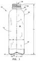
- Fig 1is a sectional outline of an exterior surface of a bottle.
- Fig 2is a bottom plan view of the base of the bottle in Fig 1 .
- Fig 3is a sectional outline view of the base taken along line 3 - 3 of Fig 2 .
- Fig 4is an enlarged view of a portion of the left side of Fig 3 .
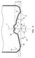
- Fig 5is an enlarged view of a portion of the right side of Fig 3 .
- a bottle 10is shown in Fig 1 and the other Figs that has a generally cylindrical body 12 surrounding a longitudinal axis Y and a closed base 1 that is unitary with the remainder of the bottle.
- the 14 basehas a continuous standing ring 16 to support the bottle 10 on any underlying support surface.
- the standing ring 16has a standing ring diameter D.
- a side wall 18is formed unitarily with the base 14 and extends from the base upward to an upper end 20 of the side wall 18.
- a neck 22is unitarily connected to the upper end 20 of the side wall 18 by a shoulder portion 21.
- the neck 22includes a finish 24 adapted to receive a cap (not shown) to close an opening 26 into the bottle interior 28.
- the bottle 10has a height H defined by the distance between the opening 26 and the standing ring 16, and a maximum width W across the bottle 10.
- the base standing ring 16is defined in vertical cross-section by a continuous curve of radius R s , shown in Figs 4 and 5 , which can be between 0.254 cm and 0.762 cm (0.100 inches and 0.300 inches).
- the radius R Sis independent of the standing ring diameter D, where the standing ring diameter D is measured at the lowest point on the standing ring 16.
- the curve defining the standing ring 16, being continuous,does not include any flattened portion in the plane X defined by the standing ring, shown in Fig 3 .
- the base standing ring 16has a diameter D less than 80% of the maximum side wall width W.
- the base standing ring 16can have a diameter D greater than 70% of the maximum side wall width W.
- the continuous curve of the base standing ring 16 defined by R Sis bounded on a radial inside, starting about at point or ring 30, by an interior region 32.
- the interior region 32can include a plurality of concave domed wedge-shaped sections 34 as seen in Fig 2 .
- the concave domed wedge-shaped sections 34can be formed by a constant inside radius R C of at least 1.0 times the standing ring diameter D as shown in Figs 3 and 5 .
- the angle of tangency at the point of intersection 30 of the concave dome portions 34 and the curve defining the standing ring 16 measured from the plane X as shown in Fig 5can be between 45° and 55°.
- the wedge-shaped sections 34can be interspaced with buttress sections 36, which can also be wedge-shaped.
- the buttress sections 36can have substantially planar inclined outer portions 38.
- the planar outer portions 38can be inclined at an angle ⁇ of between 8° and 16° with respect to a plane X defined by the base standing ring 16 as seen in Fig 4 .
- the buttress sections 36can include inner portions 40 defined by a concave surface 42 that becomes circumferentially continuous as it approaches a central downwardly protruding portion 44 surrounding the axis Y of the bottle.
- the lowest surface of the downwardly protruding section 44can be spaced above the plane X by a distance H C of 14% to 20% of the standing ring diameter D.
- the continuous curve of the base standing ring 16 defined by radius R Sis bounded on a radial outside by a conic section portion 46 starting at point or ring 48 and extending linearly upwardly and outwardly to point or ring 50 as shown in Figs 4 and 5 .
- the distance between point or ring 48 and point or ring 50defines the width of the conic section portion 46, which is preferably at least 0.089 cm (0.035 inches).
- the conic section portion 46is seen to be generated by the rotation around the vertical axis Y of a line generating a conic section having an included apex angle ⁇ of less than 160° as shown in Fig 3 .
- a base outer portion 52 extending outward from point 50 to the side wall 18can be formed as a torus segment defined by a constant radius R T of between about 12% and 20% of the standing ring diameter D.
- the material forming the standing ring 16preferably has an average thickness of between 1.0 and 1.3 times the thickness of the material forming the side wall 18. Between the point or ring 30 and the point or ring 48, the thickness of the material forming the standing ring 16 desirably has a variation that is as small as possible and less than ⁇ 20%.
- a bottle 10 as shown in Fig 1can have a height H of 22.39 cm (8.813 inches) and a maximum width W of 6.40 cm (2.52 inches).
- the standing ring diameter D of the example bottlecan be 4.826 cm (1.90 inches).
- the vertical cross-section radius R S defining the exterior surface of the standing ring 16 of the example bottlecan be 0.381 cm (0.150 inches.
- the width of the conic section portion 46 of the example bottlecan be 0.163 cm (0.064 inches).
- the average thickness of the material forming the side wall 16 of the example bottlecan be 0.0356 cm (0.014 inches) while the average thickness of the material forming the standing ring can be 0.0406 cm (0.016 inches).
- the inside radius R C forming the concave surfaces of the domed wedge-shaped sections 34 of the example bottlecan be 5.055 cm (1.990 inches).
- the angle of tangency at the point of intersection 30 of the concave dome portions 34 and the curve defining the standing ring 16 measured from the plane X in the example bottlecan be 50°.
- the angle of inclination ⁇ of the planar outer portions 38 of the buttress sections 36 of the example bottlecan be 11°.
- the radius R C defining the concave surface 40 of the example bottlecan be 0.668 cm (0.263 inches).
- the lowest surface of the central downwardly protruding portion 44 of the example bottlecan be spaced above the plane X by a distance of 0.800 cm (0.315 inches).
- the apex angle ⁇ of the conic section generating the portion 46 of the example bottlecan be 150°.
- the radius R T forming the base outer portion 52 of the example bottlecan be 0.762 cm (0.300 inches).
- the example bottleshowed a 36% improvement in perpendicularity over a prior design.
Landscapes
- Engineering & Computer Science (AREA)
- Ceramic Engineering (AREA)
- Mechanical Engineering (AREA)
- Containers Having Bodies Formed In One Piece (AREA)
- Pressure Vessels And Lids Thereof (AREA)
Abstract
Description
- The present disclosure is directed to plastic bottles, and particularly to a supporting champagne style base that is unitary with the remainder of the bottle, which improves the perpendicularity of the bottle.
- Plastic bottles that include a base having a continuous uninterrupted standing ring for supporting the bottle on any underlying surface are sometimes referred to having a champagne style base. The perpendicularity or vertical alignment of such bottles can depend on the evenness of material distribution in the area of the standing ring, particularly when the bottles are subjected to even small internal pressures of 103.45 kP (15 psi; 775 torr) or less. While small variations from a true vertical alignment can be tolerated, any significant variation may cause problems in subsequent labeling and boxing of such bottles. While a large diameter standing ring is generally thought to provide enhanced stability as a result of the larger foot print, the large diameter standing ring is more flexible as a result of less material being present in the standing ring. As a result, even small variations in material distribution in large diameter standing rings can lead to unacceptable variations in the vertical alignment or perpendicularity of the bottle. This problem has in the past been addressed by forming a preform with significant non-uniform wall thicknesses so that a substantial amount of material is placed in the chime in direct alignment with the standing ring. Examples are to be found in
US Patents 4,725,464 ;4,780,257 ;4,889,752 and6,248,413 . US Published Application 2004/0251258 discloses in Figs 22 and 23 a blow-molded thin wall plastic container "Ae" having a circular cross section with a neck 80, a shoulder 81, a body 82 and a bottom 83. The bottom 83 includes a peripheral wall 88 and a bottom wall 89, of which the peripheral wall 88 is inclined by a predetermined angle and has its lower end 88a linked to grounding bottom edge wall 89a of the bottom wall 89 having an upwardly curved surface 89 at the center thereof. The outer periphery of the grounding bottom edge wall 89a of the bottom wall 89 has a diameter remarkably smaller than that of the peripheral wall 85 of the body. The lower end 88a of the peripheral wall 88 is so inclined as to be connected to the outer periphery of the grounding bottom edge wall 89a of the bottom wall 89. The bottom 83 is distinguished by a transversal rib 91 arranged under the peripheral wall 88 of the bottom to surround the entire periphery of the container. Both the zone connecting the upper wall section 91a and the lower wall section 91 b of the transversal rib 91 and the zone connecting the upper wall section 91 a and the lower wall section 91 b show an arcuate profile. The lower walls section 91 b of the transversal rib 91 and the peripheral wall 88 of the bottom define a predetermined angle. In connection with the angle of inclination of the peripheral wall 88, the lower wall section 91 b of the transversal rib 91 is substantially vertical while the upper wall section 91 a is slightly inclined. The wall thickness t1 of the lower end 88a of the peripheral wall 88 of the bottom is greater than the wall thickness t2 of the peripheral wall 85 of the body because the lower end 88a has a diameter and a blow ratio smaller than those of the peripheral wall 88. Additionally, the lower wall section 91 b of the transversal rib 91 is substantially vertical while the wall thickness of the transversal rib 91 is increased at and near the grounding bottom edge wall 89a of the bottom wall 89.- Japan Published Application
JP 55 163 137 A Figs 1 ,2 ,4A and 4C as being inwardly inclined, and an inner peripheral wall portion in the form of a truncated cone is shown inFigs 2 ,4A and 4B . The pressure resisting properties of the bottom are said to be secured by the truncated cone inner peripheral wall portion and a central portion of the bottom wall having a convex curved surface continuously formed thereabove. The annular portion in contact with the ground has a small radius of curvature as shown inFigs 2 and4A that can often exhibit insufficient biaxial orientation during molding. Thus, the annular portion in contact with the ground is further expanded inFig 4C into a semi-circular shape in cross-section to provide a larger radius of curvature. However, when the radius of curvature increases, the pressure resisting strength of the entire base decreases so that the central portion of the bottom is easily deformed due to the internal pressure from carbonated beverages, or the like. - A significant disadvantage of using preforms having significant non-uniform wall thicknesses to place additional material in the chime in direct alignment with the standing ring is the additional polymer itself, which increases the cost of the bottle. There is thus a need for a lower-cost solution to enhance the perpendicularity or vertical alignment of blow molded plastic bottles having a champagne style base.
- The problem of the prior art is solved by the features of the independent claims 1 and 2.
- A plastic bottle has a base centered on a vertical axis. The base has a continuous standing ring to support the bottle on any underlying support surface. A side wall is formed unitarily with the base and extends from the base upward to an upper end of the side wall. A neck is unitarily connected to the upper end of the side wall that includes a finish adapted to receive a cap to close an opening into the bottle interior. The bottle has a height defined by the distance between the opening and the standing ring, and a maximum width across the bottle. To enhance the vertical alignment or perpendicularity of the bottle, the base standing ring is defined in vertical cross-section by a continuous curve. The base standing ring has a diameter less than 80% of the maximum side wall width. The continuous curve of the base standing ring is bounded on a radial outside by a conic section portion centered on the vertical axis. The vertical alignment or perpendicularity of the bottle can be further enhanced by limiting the average standing ring thickness to between 1.0 and 1.3 times the thickness of the side wall, (claim 1), or the continuous curve of the base standing ring is bounded on a radial inside by an interior region that includes a plurality of concave domed wedge-shaped sections interspaced with buttress sections having substantially planar inclined outer portions, wherein the buttress sections have inclined outer portions that are inclined at an angle of between 8° and 16° with respect to a plane defined by the base standing ring (claim 2).
- The vertical alignment or perpendicularity of the bottle can be enhanced by limiting the apex angle of the conic section portion to less than 160°. The vertical alignment or perpendicularity of the bottle can be further enhanced by maintaining the width of the conic section portion to at least 0.889 cm (0.035 inches).
- The vertical alignment or perpendicularity of the bottle can also be enhanced by limiting the standing ring diameter to be more than 70% of the maximum bottle side wall width. The vertical alignment or perpendicularity of the bottle can be further enhanced by limiting variation in the standing ring thickness to less than ± 20%. Another feature of the base that can improve the vertical alignment or perpendicularity of the bottle is confining the vertical cross-sectional radius defining the standing ring to between 0.254 cm and 0.762 cm (0.100 inches and 0.300 inches).
- Another feature of the base that can improve the vertical alignment or perpendicularity of the bottle is limiting the curvature of the concave dome portion to a radius of at least 1.0 times the standing ring diameter. The vertical alignment or perpendicularity of the bottle can be further enhanced by providing the angle of tangency at the point of intersection of the concave dome portion and the standing ring vertical cross-section to be at least 45°.
- Other features of the present bottle base and the corresponding advantages of those features will become apparent from the following discussion of the preferred embodiments of the present container, exemplifying the best mode of practice, which is illustrated in the accompanying drawings. The components in the figures are not necessarily to scale, emphasis instead being placed upon illustrating the principles of the features. Moreover, in the figures, like referenced numerals designate corresponding parts throughout the different views.
Fig 1 is a sectional outline of an exterior surface of a bottle.Fig 2 is a bottom plan view of the base of the bottle inFig 1 .Fig 3 is a sectional outline view of the base taken along line 3 - 3 ofFig 2 .Fig 4 is an enlarged view of a portion of the left side ofFig 3 .Fig 5 is an enlarged view of a portion of the right side ofFig 3 .- A
bottle 10 is shown inFig 1 and the other Figs that has a generallycylindrical body 12 surrounding a longitudinal axis Y and a closed base 1 that is unitary with the remainder of the bottle. The 14 base has a continuous standingring 16 to support thebottle 10 on any underlying support surface. The standingring 16 has a standing ring diameter D.A side wall 18 is formed unitarily with thebase 14 and extends from the base upward to anupper end 20 of theside wall 18. Aneck 22 is unitarily connected to theupper end 20 of theside wall 18 by ashoulder portion 21. Theneck 22 includes afinish 24 adapted to receive a cap (not shown) to close anopening 26 into thebottle interior 28. Thebottle 10 has a height H defined by the distance between the opening 26 and the standingring 16, and a maximum width W across thebottle 10. - To enhance the vertical alignment or perpendicularity of the
bottle 10, thebase standing ring 16 is defined in vertical cross-section by a continuous curve of radius Rs, shown inFigs 4 and5 , which can be between 0.254 cm and 0.762 cm (0.100 inches and 0.300 inches). The radius RS is independent of the standing ring diameter D, where the standing ring diameter D is measured at the lowest point on the standingring 16. The curve defining the standingring 16, being continuous, does not include any flattened portion in the plane X defined by the standing ring, shown inFig 3 . Thebase standing ring 16 has a diameter D less than 80% of the maximum side wall width W. Thebase standing ring 16 can have a diameter D greater than 70% of the maximum side wall width W. - The continuous curve of the
base standing ring 16 defined by RS is bounded on a radial inside, starting about at point orring 30, by aninterior region 32. Theinterior region 32 can include a plurality of concave domed wedge-shapedsections 34 as seen inFig 2 . The concave domed wedge-shapedsections 34 can be formed by a constant inside radius RC of at least 1.0 times the standing ring diameter D as shown inFigs 3 and5 . The angle of tangency at the point ofintersection 30 of theconcave dome portions 34 and the curve defining the standingring 16 measured from the plane X as shown inFig 5 can be between 45° and 55°. The wedge-shapedsections 34 can be interspaced with buttresssections 36, which can also be wedge-shaped. The buttresssections 36 can have substantially planar inclinedouter portions 38. The planarouter portions 38 can be inclined at an angle θ of between 8° and 16° with respect to a plane X defined by thebase standing ring 16 as seen inFig 4 . The buttresssections 36 can includeinner portions 40 defined by aconcave surface 42 that becomes circumferentially continuous as it approaches a central downwardly protrudingportion 44 surrounding the axis Y of the bottle. The lowest surface of the downwardly protrudingsection 44 can be spaced above the plane X by a distance HC of 14% to 20% of the standing ring diameter D. - The continuous curve of the
base standing ring 16 defined by radius RS is bounded on a radial outside by aconic section portion 46 starting at point orring 48 and extending linearly upwardly and outwardly to point orring 50 as shown inFigs 4 and5 . The distance between point orring 48 and point orring 50 defines the width of theconic section portion 46, which is preferably at least 0.089 cm (0.035 inches). Theconic section portion 46 is seen to be generated by the rotation around the vertical axis Y of a line generating a conic section having an included apex angle Φ of less than 160° as shown inFig 3 . A baseouter portion 52 extending outward frompoint 50 to theside wall 18 can be formed as a torus segment defined by a constant radius RT of between about 12% and 20% of the standing ring diameter D. - Between the point or 30 and the point or
ring 48, the material forming the standingring 16 preferably has an average thickness of between 1.0 and 1.3 times the thickness of the material forming theside wall 18. Between the point orring 30 and the point orring 48, the thickness of the material forming the standingring 16 desirably has a variation that is as small as possible and less than ± 20%. - By way of example, a
bottle 10 as shown inFig 1 can have a height H of 22.39 cm (8.813 inches) and a maximum width W of 6.40 cm (2.52 inches). The standing ring diameter D of the example bottle can be 4.826 cm (1.90 inches). The vertical cross-section radius RS defining the exterior surface of the standingring 16 of the example bottle can be 0.381 cm (0.150 inches. The width of theconic section portion 46 of the example bottle can be 0.163 cm (0.064 inches). The average thickness of the material forming theside wall 16 of the example bottle can be 0.0356 cm (0.014 inches) while the average thickness of the material forming the standing ring can be 0.0406 cm (0.016 inches). The inside radius RC forming the concave surfaces of the domed wedge-shapedsections 34 of the example bottle can be 5.055 cm (1.990 inches). The angle of tangency at the point ofintersection 30 of theconcave dome portions 34 and the curve defining the standingring 16 measured from the plane X in the example bottle can be 50°. The angle of inclination θ of the planarouter portions 38 of the buttresssections 36 of the example bottle can be 11°. The radius RC defining theconcave surface 40 of the example bottle can be 0.668 cm (0.263 inches). The lowest surface of the central downwardly protrudingportion 44 of the example bottle can be spaced above the plane X by a distance of 0.800 cm (0.315 inches). The apex angle Φ of the conic section generating theportion 46 of the example bottle can be 150°. The radius RT forming the baseouter portion 52 of the example bottle can be 0.762 cm (0.300 inches). The example bottle showed a 36% improvement in perpendicularity over a prior design.
Claims (9)
- A plastic bottle (10) including a base (14) centered on a vertical axis (Y), the base having a standing ring (16) to support the bottle on any underlying support surface, a side wall (18) formed unitarily with the base and extending from the base upward to an upper end (20) of the side wall, and a neck (22) connected to the upper end of the side wall, the neck including a finish (24) adapted to receive a cap to close an opening (26) into the bottle interior, the bottle having a height (H) defined by the distance between the opening and the standing ring, and a maximum width (W) across the side wall, the base standing ring being defined in vertical cross-section by a continuous curve bounded on a radial inside by an interior region (32), the continuous curve being bounded on a radial outside by a conic section portion (46) centered on the vertical axis, the base standing ring having a diameter (D) less than 80% of the maximum side wall width andcharacterized by the standing ring (16) having an average thickness that is between 1.0 and 1.3 times the average thickness of the side wall (18).
- A plastic bottle (10) including a base (14) centered on a vertical axis (Y), the base having a standing ring (16) to support the bottle on any underlying support surface, a side wall (18) formed unitarily with the base and extending from the base upward to an upper end (20) of the side wall, and a neck (22) connected to the upper end of the side wall, the neck including a finish (24) adapted to receive a cap to close an opening (26) into the bottle interior, the bottle having a height (H) defined by the distance between the opening and the standing ring, and a maximum width (W) across the side wall, the base standing ring being defined in vertical cross-section by a continuous curve bounded on a radial inside by an interior region (32), the interior region comprises a concave domed shaped portion, the continuous curve being bounded on a radial outside by a conic section portion (46) centered on the vertical axis, the base standing ring having a diameter (D) less than 80% of the maximum side wall width andcharacterized by the concave domed shaped portion having a plurality of concave domed wedge-shaped sections (34) interspaced with buttress sections (36) and the buttress sections having substantially planar inclined outer portions (38) inclined at an angle (θ) of between 8° and 16° with respect to a plane (X) defined by the base standing ring.
- The plastic bottle of claim 1 or 2, wherein the base standing ring diameter (D) is more than 70% of the maximum side wall width (W).
- The plastic bottle of either of claims 2 or 3, wherein the standing ring (16) has an average thickness that is between 1.0 and 1.3 times the average thickness of the side wall (18).
- The plastic bottle of any of claims 1 - 4, wherein the variation in thickness around the circumference of the standing ring (16) is less than ± 20%.
- The plastic bottle of any of claims 1 - 5, wherein the continuous curve of the standing ring has a defining radius (RS) in vertical cross-section of between 2.54 mm (0.100 inches) and 7.62 mm (0.300 inches).
- The plastic bottle of any of claims 2 - 6, wherein the concave domed wedge-shaped sections (34) are defined by a curve (RC) having a radius of at least 1.0 times the standing ring diameter (D).
- The plastic bottle of any of claims 1 - 7, wherein the conic section portion (46) outside the base standing ring (16) has a width of between 0.889 mm (0.035 inches) and 2.413 mm (0.095 inches).
- The plastic bottle of any of claims 1 - 8, wherein the conic section portion (46) has an apex angle (Φ) of less than 160°.
Applications Claiming Priority (1)
| Application Number | Priority Date | Filing Date | Title |
|---|---|---|---|
| US12/552,025US20110049083A1 (en) | 2009-09-01 | 2009-09-01 | Base for pressurized bottles |
Publications (2)
| Publication Number | Publication Date |
|---|---|
| EP2289809A1 EP2289809A1 (en) | 2011-03-02 |
| EP2289809B1true EP2289809B1 (en) | 2012-04-04 |
Family
ID=43127269
Family Applications (1)
| Application Number | Title | Priority Date | Filing Date |
|---|---|---|---|
| EP10075356ANot-in-forceEP2289809B1 (en) | 2009-09-01 | 2010-08-19 | Base for pressurized bottles |
Country Status (3)
| Country | Link |
|---|---|
| US (1) | US20110049083A1 (en) |
| EP (1) | EP2289809B1 (en) |
| AT (1) | ATE552177T1 (en) |
Cited By (1)
| Publication number | Priority date | Publication date | Assignee | Title |
|---|---|---|---|---|
| CN104097822A (en)* | 2013-04-10 | 2014-10-15 | 克朗斯机械(太仓)有限公司 | Plastic bottle with flexible base section |
Families Citing this family (42)
| Publication number | Priority date | Publication date | Assignee | Title |
|---|---|---|---|---|
| US7900425B2 (en) | 2005-10-14 | 2011-03-08 | Graham Packaging Company, L.P. | Method for handling a hot-filled container having a moveable portion to reduce a portion of a vacuum created therein |
| NZ521694A (en) | 2002-09-30 | 2005-05-27 | Co2 Pac Ltd | Container structure for removal of vacuum pressure |
| US8381940B2 (en) | 2002-09-30 | 2013-02-26 | Co2 Pac Limited | Pressure reinforced plastic container having a moveable pressure panel and related method of processing a plastic container |
| US7543713B2 (en) | 2001-04-19 | 2009-06-09 | Graham Packaging Company L.P. | Multi-functional base for a plastic, wide-mouth, blow-molded container |
| NZ569422A (en) | 2003-07-30 | 2010-02-26 | Graham Packaging Co | Container filling with base projection inverted during transportation, and being pushed up after filling |
| US8017065B2 (en)* | 2006-04-07 | 2011-09-13 | Graham Packaging Company L.P. | System and method for forming a container having a grip region |
| US9707711B2 (en) | 2006-04-07 | 2017-07-18 | Graham Packaging Company, L.P. | Container having outwardly blown, invertible deep-set grips |
| US8747727B2 (en) | 2006-04-07 | 2014-06-10 | Graham Packaging Company L.P. | Method of forming container |
| US8627944B2 (en) | 2008-07-23 | 2014-01-14 | Graham Packaging Company L.P. | System, apparatus, and method for conveying a plurality of containers |
| US7926243B2 (en) | 2009-01-06 | 2011-04-19 | Graham Packaging Company, L.P. | Method and system for handling containers |
| AT510506B1 (en)* | 2010-09-22 | 2013-01-15 | Red Bull Gmbh | FLOOR CONSTRUCTION FOR A PLASTIC BOTTLE |
| US8962114B2 (en) | 2010-10-30 | 2015-02-24 | Graham Packaging Company, L.P. | Compression molded preform for forming invertible base hot-fill container, and systems and methods thereof |
| US9994378B2 (en) | 2011-08-15 | 2018-06-12 | Graham Packaging Company, L.P. | Plastic containers, base configurations for plastic containers, and systems, methods, and base molds thereof |
| US9150320B2 (en) | 2011-08-15 | 2015-10-06 | Graham Packaging Company, L.P. | Plastic containers having base configurations with up-stand walls having a plurality of rings, and systems, methods, and base molds thereof |
| MX353418B (en) | 2011-08-31 | 2018-01-11 | Amcor Group Gmbh | Lightweight container base. |
| US10532848B2 (en) | 2011-08-31 | 2020-01-14 | Amcor Rigid Plastics Usa, Llc | Lightweight container base |
| US10538357B2 (en) | 2011-08-31 | 2020-01-21 | Amcor Rigid Plastics Usa, Llc | Lightweight container base |
| US8919587B2 (en) | 2011-10-03 | 2014-12-30 | Graham Packaging Company, L.P. | Plastic container with angular vacuum panel and method of same |
| FR2991302B1 (en)* | 2012-05-31 | 2014-07-04 | Sidel Participations | CONTAINER HAVING A BACKGROUND PROVIDED WITH A DECOUCHEMENT VOUTE |
| MX354327B (en)* | 2012-08-31 | 2018-02-26 | Amcor Group Gmbh | Lightweight container base. |
| US10513364B2 (en) | 2013-01-15 | 2019-12-24 | Graham Packaging Company, L.P. | Variable displacement container base |
| JP6337381B2 (en) | 2013-01-15 | 2018-06-06 | グレイアム パッケイジング カンパニー リミテッド パートナーシップ | Variable displacement container bottom |
| DE102013101332A1 (en) | 2013-02-11 | 2014-08-14 | Krones Ag | Plastic container |
| US9254937B2 (en) | 2013-03-15 | 2016-02-09 | Graham Packaging Company, L.P. | Deep grip mechanism for blow mold and related methods and bottles |
| US9022776B2 (en) | 2013-03-15 | 2015-05-05 | Graham Packaging Company, L.P. | Deep grip mechanism within blow mold hanger and related methods and bottles |
| EP3046865B1 (en)* | 2013-09-19 | 2017-05-03 | Sidel Participations | Machine and method for processing filled containers having an invertible diaphragm |
| JP6465664B2 (en)* | 2015-01-22 | 2019-02-06 | 三笠産業株式会社 | container |
| USD799967S1 (en)* | 2016-01-15 | 2017-10-17 | Industries Lassonde Inc. | Plastic bottle |
| JP6143213B1 (en)* | 2016-03-04 | 2017-06-07 | 三菱ケミカル株式会社 | Plastic bottle |
| CA3066847A1 (en)* | 2017-06-12 | 2018-12-20 | Societe Des Produits Nestle S.A. | Container bottom base provided with a bi-concave arch |
| USD878919S1 (en)* | 2017-08-18 | 2020-03-24 | Design 24 Societa Benefit S.R.L. | Bottle |
| CA3070970C (en) | 2017-08-25 | 2024-02-06 | Graham Packaging Company, L.P. | Variable displacement base and container and method of using the same |
| JP2019182502A (en)* | 2018-04-12 | 2019-10-24 | 大日本印刷株式会社 | Pet bottle |
| CA3106614A1 (en) | 2018-07-23 | 2020-01-30 | Co2Pac Limited | Variable displacement container base |
| JP7331422B2 (en)* | 2019-04-04 | 2023-08-23 | 大日本印刷株式会社 | warming plastic container |
| USD973440S1 (en)* | 2020-07-21 | 2022-12-27 | 24Bottles Sociata Benefit Srl | Bottle |
| CN112797306B (en)* | 2021-02-02 | 2024-12-03 | 承德锋宇金属制品有限公司 | A C219 steel cylinder with a large outer diameter at the grounding point |
| USD997734S1 (en)* | 2021-08-11 | 2023-09-05 | Eco Alpha Ltd | Bottle |
| DE102021127061A1 (en) | 2021-10-19 | 2023-04-20 | Krones Aktiengesellschaft | Plastic container for holding drinks with improved stability |
| USD1038696S1 (en)* | 2021-12-25 | 2024-08-13 | Reuben Boyd | Water bottle with embedded challenge coin |
| US12054304B2 (en) | 2022-06-03 | 2024-08-06 | Abbott Laboratories | Reclosable plastic bottle with waist and strengthening rib(s) |
| US11970324B2 (en)* | 2022-06-06 | 2024-04-30 | Envases USA, Inc. | Base of a plastic container |
Family Cites Families (35)
| Publication number | Priority date | Publication date | Assignee | Title |
|---|---|---|---|---|
| US64759A (en)* | 1867-05-14 | gratten | ||
| US1532276A (en)* | 1924-03-12 | 1925-04-07 | Elmer F Swartz | Stock feeder |
| US2858801A (en)* | 1955-08-16 | 1958-11-04 | Kenneth E Chance | Animal feeding structure |
| US2933063A (en)* | 1959-07-17 | 1960-04-19 | Petrus J Geerlings | Transparent cover for hog feeder |
| US4077359A (en)* | 1976-04-19 | 1978-03-07 | Aldo Amurri | Stable structure for cattle self-feeding and open air pen cattle breeding |
| JPS55163137A (en)* | 1979-05-31 | 1980-12-18 | Yoshizaki Kozo | Plasticcmade pressure container and making method thereof |
| US4247012A (en)* | 1979-08-13 | 1981-01-27 | Sewell Plastics, Inc. | Bottom structure for plastic container for pressurized fluids |
| US4381061A (en)* | 1981-05-26 | 1983-04-26 | Ball Corporation | Non-paneling container |
| US4465199A (en)* | 1981-06-22 | 1984-08-14 | Katashi Aoki | Pressure resisting plastic bottle |
| SE428775B (en)* | 1981-11-26 | 1983-07-25 | Plm Ab | CONTAINERS AND SETS AND APPARATUS FOR MAKING A SUGAR |
| US4880129A (en)* | 1983-01-05 | 1989-11-14 | American National Can Company | Method of obtaining acceptable configuration of a plastic container after thermal food sterilization process |
| JPS6076613U (en)* | 1983-10-31 | 1985-05-29 | 日精エー・エス・ビー機械株式会社 | Heat-resistant synthetic resin bottle |
| US4580528A (en)* | 1984-10-16 | 1986-04-08 | Gunyah Nominees Pty. Ltd. | Feeding apparatus for animals |
| US4725464A (en) | 1986-05-30 | 1988-02-16 | Continental Pet Technologies, Inc. | Refillable polyester beverage bottle and preform for forming same |
| US4780257A (en) | 1987-05-29 | 1988-10-25 | Devtech, Inc. | One piece self-standing blow molded plastic bottles |
| US4927679A (en)* | 1987-05-29 | 1990-05-22 | Devtech, Inc. | Preform for a monobase container |
| US4889752A (en) | 1987-05-29 | 1989-12-26 | Devtech, Inc. | One piece self-standing blow molded plastic containers |
| US4894268A (en)* | 1987-12-07 | 1990-01-16 | Sonoco Products Company | Stretch blow-molded polyethylene terephthalate wide mouth container and intermediate article |
| US5198248A (en)* | 1990-03-05 | 1993-03-30 | Continental Pet Technologies, Inc. | Blow mold for forming a refillable polyester container |
| US5234126A (en)* | 1991-01-04 | 1993-08-10 | Abbott Laboratories | Plastic container |
| US5217737A (en)* | 1991-05-20 | 1993-06-08 | Abbott Laboratories | Plastic containers capable of surviving sterilization |
| US5375559A (en)* | 1994-01-24 | 1994-12-27 | Baadsgaard; Glen M. | Portable livestock feeder |
| US5630375A (en)* | 1995-03-31 | 1997-05-20 | Mann; Fred W. | Livestock feeder |
| IT1289367B1 (en) | 1996-03-07 | 1998-10-02 | Sipa Spa | PREFORMS IN THERMOPLASTIC RESIN AND RELATED PRODUCTION PROCESS |
| JP2000128140A (en)* | 1998-10-20 | 2000-05-09 | Aoki Technical Laboratory Inc | Polyester resin-made heat-resistant packaging container |
| US6752284B1 (en)* | 1999-02-27 | 2004-06-22 | Yoshino Kogyosho Co., Ltd. | Synthetic resin container with thin wall |
| US6634517B2 (en)* | 2001-09-17 | 2003-10-21 | Crown Cork & Seal Technologies Corporation | Base for plastic container |
| US6769561B2 (en)* | 2001-12-21 | 2004-08-03 | Ball Corporation | Plastic bottle with champagne base |
| US6637369B1 (en)* | 2002-05-30 | 2003-10-28 | Dennis L. Landon | Covered livestock feeder for field use |
| US6942116B2 (en)* | 2003-05-23 | 2005-09-13 | Amcor Limited | Container base structure responsive to vacuum related forces |
| FR2856380B1 (en)* | 2003-06-19 | 2005-10-21 | Sidel Sa | CONTAINER IN THERMOPLASTIC MATERIAL AND CHAMPAGNE BASE |
| US20050217593A1 (en)* | 2004-04-05 | 2005-10-06 | Rice Andrew D | Covered animal feeder with mounting brackets |
| US7416089B2 (en)* | 2004-12-06 | 2008-08-26 | Constar International Inc. | Hot-fill type plastic container with reinforced heel |
| US20070163505A1 (en)* | 2006-01-13 | 2007-07-19 | Sydell Incorporated | Dispenser feeder with removable rain guard extension |
| US7732035B2 (en)* | 2006-03-07 | 2010-06-08 | Plastipak Packaging, Inc. | Base for plastic container |
- 2009
- 2009-09-01USUS12/552,025patent/US20110049083A1/ennot_activeAbandoned
- 2010
- 2010-08-19ATAT10075356Tpatent/ATE552177T1/enactive
- 2010-08-19EPEP10075356Apatent/EP2289809B1/ennot_activeNot-in-force
Cited By (2)
| Publication number | Priority date | Publication date | Assignee | Title |
|---|---|---|---|---|
| CN104097822A (en)* | 2013-04-10 | 2014-10-15 | 克朗斯机械(太仓)有限公司 | Plastic bottle with flexible base section |
| CN104097822B (en)* | 2013-04-10 | 2018-05-01 | 克朗斯机械(太仓)有限公司 | Plastic bottle with flexible base section |
Also Published As
| Publication number | Publication date |
|---|---|
| ATE552177T1 (en) | 2012-04-15 |
| EP2289809A1 (en) | 2011-03-02 |
| US20110049083A1 (en) | 2011-03-03 |
Similar Documents
| Publication | Publication Date | Title |
|---|---|---|
| EP2289809B1 (en) | Base for pressurized bottles | |
| US11987416B2 (en) | Plastic container | |
| US6065624A (en) | Plastic blow molded water bottle | |
| US6634517B2 (en) | Base for plastic container | |
| EP1440008B1 (en) | Plastic bottle with champagne base | |
| US5217128A (en) | Thermoplastic bottle with reinforcing ribs | |
| US4247012A (en) | Bottom structure for plastic container for pressurized fluids | |
| US6176382B1 (en) | Plastic container having base with annular wall and method of making the same | |
| US5988416A (en) | Footed container and base therefor | |
| EP0479695B1 (en) | Wide stance footed bottle | |
| US5714111A (en) | One piece self-standing blow molded plastic containers made from a monobase preform | |
| US4368825A (en) | Self-standing bottle structure | |
| JP2011251772A (en) | Container made of thermoplastic resin | |
| AU2002342701A1 (en) | Base for plastic container | |
| US20120181246A1 (en) | Panelless hot-fill plastic bottle | |
| US10196168B2 (en) | Container having a bottom provided with a stepped arch | |
| GB2524154A (en) | Improved self-standing container | |
| US20010001200A1 (en) | Blow molded plastic container and method of making | |
| EP0441966B1 (en) | Bottle made of synthetic resin | |
| JP7451989B2 (en) | Synthetic resin container | |
| JP6999265B2 (en) | Resin container | |
| AU721474B2 (en) | Blow molded container and method of making | |
| MXPA99009834A (en) | Plastic bottle for water, molded by sopl |
Legal Events
| Date | Code | Title | Description |
|---|---|---|---|
| PUAI | Public reference made under article 153(3) epc to a published international application that has entered the european phase | Free format text:ORIGINAL CODE: 0009012 | |
| AK | Designated contracting states | Kind code of ref document:A1 Designated state(s):AL AT BE BG CH CY CZ DE DK EE ES FI FR GB GR HR HU IE IS IT LI LT LU LV MC MK MT NL NO PL PT RO SE SI SK SM TR | |
| AX | Request for extension of the european patent | Extension state:BA ME RS | |
| RAP1 | Party data changed (applicant data changed or rights of an application transferred) | Owner name:AMCOR RIGID PLASTICS USA, INC. | |
| GRAP | Despatch of communication of intention to grant a patent | Free format text:ORIGINAL CODE: EPIDOSNIGR1 | |
| 17P | Request for examination filed | Effective date:20110830 | |
| RIC1 | Information provided on ipc code assigned before grant | Ipc:B65D 1/02 20060101AFI20111003BHEP | |
| GRAS | Grant fee paid | Free format text:ORIGINAL CODE: EPIDOSNIGR3 | |
| GRAA | (expected) grant | Free format text:ORIGINAL CODE: 0009210 | |
| AK | Designated contracting states | Kind code of ref document:B1 Designated state(s):AL AT BE BG CH CY CZ DE DK EE ES FI FR GB GR HR HU IE IS IT LI LT LU LV MC MK MT NL NO PL PT RO SE SI SK SM TR | |
| REG | Reference to a national code | Ref country code:GB Ref legal event code:FG4D | |
| REG | Reference to a national code | Ref country code:CH Ref legal event code:EP | |
| REG | Reference to a national code | Ref country code:AT Ref legal event code:REF Ref document number:552177 Country of ref document:AT Kind code of ref document:T Effective date:20120415 | |
| REG | Reference to a national code | Ref country code:IE Ref legal event code:FG4D | |
| REG | Reference to a national code | Ref country code:DE Ref legal event code:R096 Ref document number:602010001211 Country of ref document:DE Effective date:20120531 | |
| REG | Reference to a national code | Ref country code:NL Ref legal event code:VDEP Effective date:20120404 | |
| REG | Reference to a national code | Ref country code:AT Ref legal event code:MK05 Ref document number:552177 Country of ref document:AT Kind code of ref document:T Effective date:20120404 | |
| LTIE | Lt: invalidation of european patent or patent extension | Effective date:20120404 | |
| PG25 | Lapsed in a contracting state [announced via postgrant information from national office to epo] | Ref country code:PL Free format text:LAPSE BECAUSE OF FAILURE TO SUBMIT A TRANSLATION OF THE DESCRIPTION OR TO PAY THE FEE WITHIN THE PRESCRIBED TIME-LIMIT Effective date:20120404 Ref country code:IS Free format text:LAPSE BECAUSE OF FAILURE TO SUBMIT A TRANSLATION OF THE DESCRIPTION OR TO PAY THE FEE WITHIN THE PRESCRIBED TIME-LIMIT Effective date:20120804 Ref country code:CY Free format text:LAPSE BECAUSE OF FAILURE TO SUBMIT A TRANSLATION OF THE DESCRIPTION OR TO PAY THE FEE WITHIN THE PRESCRIBED TIME-LIMIT Effective date:20120404 Ref country code:NO Free format text:LAPSE BECAUSE OF FAILURE TO SUBMIT A TRANSLATION OF THE DESCRIPTION OR TO PAY THE FEE WITHIN THE PRESCRIBED TIME-LIMIT Effective date:20120704 Ref country code:SI Free format text:LAPSE BECAUSE OF FAILURE TO SUBMIT A TRANSLATION OF THE DESCRIPTION OR TO PAY THE FEE WITHIN THE PRESCRIBED TIME-LIMIT Effective date:20120404 Ref country code:LT Free format text:LAPSE BECAUSE OF FAILURE TO SUBMIT A TRANSLATION OF THE DESCRIPTION OR TO PAY THE FEE WITHIN THE PRESCRIBED TIME-LIMIT Effective date:20120404 Ref country code:SE Free format text:LAPSE BECAUSE OF FAILURE TO SUBMIT A TRANSLATION OF THE DESCRIPTION OR TO PAY THE FEE WITHIN THE PRESCRIBED TIME-LIMIT Effective date:20120404 Ref country code:FI Free format text:LAPSE BECAUSE OF FAILURE TO SUBMIT A TRANSLATION OF THE DESCRIPTION OR TO PAY THE FEE WITHIN THE PRESCRIBED TIME-LIMIT Effective date:20120404 | |
| PG25 | Lapsed in a contracting state [announced via postgrant information from national office to epo] | Ref country code:PT Free format text:LAPSE BECAUSE OF FAILURE TO SUBMIT A TRANSLATION OF THE DESCRIPTION OR TO PAY THE FEE WITHIN THE PRESCRIBED TIME-LIMIT Effective date:20120806 Ref country code:GR Free format text:LAPSE BECAUSE OF FAILURE TO SUBMIT A TRANSLATION OF THE DESCRIPTION OR TO PAY THE FEE WITHIN THE PRESCRIBED TIME-LIMIT Effective date:20120705 Ref country code:LV Free format text:LAPSE BECAUSE OF FAILURE TO SUBMIT A TRANSLATION OF THE DESCRIPTION OR TO PAY THE FEE WITHIN THE PRESCRIBED TIME-LIMIT Effective date:20120404 Ref country code:HR Free format text:LAPSE BECAUSE OF FAILURE TO SUBMIT A TRANSLATION OF THE DESCRIPTION OR TO PAY THE FEE WITHIN THE PRESCRIBED TIME-LIMIT Effective date:20120404 | |
| PG25 | Lapsed in a contracting state [announced via postgrant information from national office to epo] | Ref country code:BE Free format text:LAPSE BECAUSE OF FAILURE TO SUBMIT A TRANSLATION OF THE DESCRIPTION OR TO PAY THE FEE WITHIN THE PRESCRIBED TIME-LIMIT Effective date:20120404 | |
| PGFP | Annual fee paid to national office [announced via postgrant information from national office to epo] | Ref country code:DE Payment date:20120829 Year of fee payment:3 Ref country code:FR Payment date:20120830 Year of fee payment:3 | |
| PG25 | Lapsed in a contracting state [announced via postgrant information from national office to epo] | Ref country code:CZ Free format text:LAPSE BECAUSE OF FAILURE TO SUBMIT A TRANSLATION OF THE DESCRIPTION OR TO PAY THE FEE WITHIN THE PRESCRIBED TIME-LIMIT Effective date:20120404 Ref country code:AT Free format text:LAPSE BECAUSE OF FAILURE TO SUBMIT A TRANSLATION OF THE DESCRIPTION OR TO PAY THE FEE WITHIN THE PRESCRIBED TIME-LIMIT Effective date:20120404 Ref country code:NL Free format text:LAPSE BECAUSE OF FAILURE TO SUBMIT A TRANSLATION OF THE DESCRIPTION OR TO PAY THE FEE WITHIN THE PRESCRIBED TIME-LIMIT Effective date:20120404 Ref country code:EE Free format text:LAPSE BECAUSE OF FAILURE TO SUBMIT A TRANSLATION OF THE DESCRIPTION OR TO PAY THE FEE WITHIN THE PRESCRIBED TIME-LIMIT Effective date:20120404 Ref country code:RO Free format text:LAPSE BECAUSE OF FAILURE TO SUBMIT A TRANSLATION OF THE DESCRIPTION OR TO PAY THE FEE WITHIN THE PRESCRIBED TIME-LIMIT Effective date:20120404 Ref country code:SK Free format text:LAPSE BECAUSE OF FAILURE TO SUBMIT A TRANSLATION OF THE DESCRIPTION OR TO PAY THE FEE WITHIN THE PRESCRIBED TIME-LIMIT Effective date:20120404 Ref country code:DK Free format text:LAPSE BECAUSE OF FAILURE TO SUBMIT A TRANSLATION OF THE DESCRIPTION OR TO PAY THE FEE WITHIN THE PRESCRIBED TIME-LIMIT Effective date:20120404 | |
| PLBE | No opposition filed within time limit | Free format text:ORIGINAL CODE: 0009261 | |
| STAA | Information on the status of an ep patent application or granted ep patent | Free format text:STATUS: NO OPPOSITION FILED WITHIN TIME LIMIT | |
| PG25 | Lapsed in a contracting state [announced via postgrant information from national office to epo] | Ref country code:IT Free format text:LAPSE BECAUSE OF FAILURE TO SUBMIT A TRANSLATION OF THE DESCRIPTION OR TO PAY THE FEE WITHIN THE PRESCRIBED TIME-LIMIT Effective date:20120404 | |
| 26N | No opposition filed | Effective date:20130107 | |
| PG25 | Lapsed in a contracting state [announced via postgrant information from national office to epo] | Ref country code:MC Free format text:LAPSE BECAUSE OF NON-PAYMENT OF DUE FEES Effective date:20120831 | |
| PG25 | Lapsed in a contracting state [announced via postgrant information from national office to epo] | Ref country code:ES Free format text:LAPSE BECAUSE OF FAILURE TO SUBMIT A TRANSLATION OF THE DESCRIPTION OR TO PAY THE FEE WITHIN THE PRESCRIBED TIME-LIMIT Effective date:20120715 | |
| REG | Reference to a national code | Ref country code:DE Ref legal event code:R097 Ref document number:602010001211 Country of ref document:DE Effective date:20130107 | |
| REG | Reference to a national code | Ref country code:IE Ref legal event code:MM4A | |
| PG25 | Lapsed in a contracting state [announced via postgrant information from national office to epo] | Ref country code:IE Free format text:LAPSE BECAUSE OF NON-PAYMENT OF DUE FEES Effective date:20120819 Ref country code:BG Free format text:LAPSE BECAUSE OF FAILURE TO SUBMIT A TRANSLATION OF THE DESCRIPTION OR TO PAY THE FEE WITHIN THE PRESCRIBED TIME-LIMIT Effective date:20120704 | |
| PG25 | Lapsed in a contracting state [announced via postgrant information from national office to epo] | Ref country code:MT Free format text:LAPSE BECAUSE OF FAILURE TO SUBMIT A TRANSLATION OF THE DESCRIPTION OR TO PAY THE FEE WITHIN THE PRESCRIBED TIME-LIMIT Effective date:20120404 Ref country code:AL Free format text:LAPSE BECAUSE OF FAILURE TO SUBMIT A TRANSLATION OF THE DESCRIPTION OR TO PAY THE FEE WITHIN THE PRESCRIBED TIME-LIMIT Effective date:20120404 | |
| PG25 | Lapsed in a contracting state [announced via postgrant information from national office to epo] | Ref country code:DE Free format text:LAPSE BECAUSE OF NON-PAYMENT OF DUE FEES Effective date:20140301 Ref country code:TR Free format text:LAPSE BECAUSE OF FAILURE TO SUBMIT A TRANSLATION OF THE DESCRIPTION OR TO PAY THE FEE WITHIN THE PRESCRIBED TIME-LIMIT Effective date:20120404 | |
| REG | Reference to a national code | Ref country code:FR Ref legal event code:ST Effective date:20140430 | |
| PG25 | Lapsed in a contracting state [announced via postgrant information from national office to epo] | Ref country code:SM Free format text:LAPSE BECAUSE OF FAILURE TO SUBMIT A TRANSLATION OF THE DESCRIPTION OR TO PAY THE FEE WITHIN THE PRESCRIBED TIME-LIMIT Effective date:20120404 Ref country code:LU Free format text:LAPSE BECAUSE OF NON-PAYMENT OF DUE FEES Effective date:20120819 | |
| REG | Reference to a national code | Ref country code:DE Ref legal event code:R119 Ref document number:602010001211 Country of ref document:DE Effective date:20140301 | |
| PG25 | Lapsed in a contracting state [announced via postgrant information from national office to epo] | Ref country code:HU Free format text:LAPSE BECAUSE OF FAILURE TO SUBMIT A TRANSLATION OF THE DESCRIPTION OR TO PAY THE FEE WITHIN THE PRESCRIBED TIME-LIMIT Effective date:20100819 | |
| PG25 | Lapsed in a contracting state [announced via postgrant information from national office to epo] | Ref country code:FR Free format text:LAPSE BECAUSE OF NON-PAYMENT OF DUE FEES Effective date:20130902 | |
| REG | Reference to a national code | Ref country code:CH Ref legal event code:PL | |
| GBPC | Gb: european patent ceased through non-payment of renewal fee | Effective date:20140819 | |
| PG25 | Lapsed in a contracting state [announced via postgrant information from national office to epo] | Ref country code:CH Free format text:LAPSE BECAUSE OF NON-PAYMENT OF DUE FEES Effective date:20140831 Ref country code:LI Free format text:LAPSE BECAUSE OF NON-PAYMENT OF DUE FEES Effective date:20140831 | |
| PG25 | Lapsed in a contracting state [announced via postgrant information from national office to epo] | Ref country code:MK Free format text:LAPSE BECAUSE OF FAILURE TO SUBMIT A TRANSLATION OF THE DESCRIPTION OR TO PAY THE FEE WITHIN THE PRESCRIBED TIME-LIMIT Effective date:20120404 Ref country code:GB Free format text:LAPSE BECAUSE OF NON-PAYMENT OF DUE FEES Effective date:20140819 |