EP2289141B1 - Apparatus and method of optimizing power system efficiency using a power loss model - Google Patents
Apparatus and method of optimizing power system efficiency using a power loss modelDownload PDFInfo
- Publication number
- EP2289141B1 EP2289141B1EP09755621.1AEP09755621AEP2289141B1EP 2289141 B1EP2289141 B1EP 2289141B1EP 09755621 AEP09755621 AEP 09755621AEP 2289141 B1EP2289141 B1EP 2289141B1
- Authority
- EP
- European Patent Office
- Prior art keywords
- power
- primary
- converter
- power converter
- subsystem
- Prior art date
- Legal status (The legal status is an assumption and is not a legal conclusion. Google has not performed a legal analysis and makes no representation as to the accuracy of the status listed.)
- Not-in-force
Links
- 238000000034methodMethods0.000titleclaimsdescription28
- 230000006870functionEffects0.000claimsdescription33
- 238000001816coolingMethods0.000claimsdescription28
- 238000005259measurementMethods0.000claimsdescription26
- 230000008859changeEffects0.000claimsdescription24
- 238000004891communicationMethods0.000claimsdescription23
- 230000015654memoryEffects0.000claimsdescription14
- 238000012545processingMethods0.000claimsdescription11
- 230000000737periodic effectEffects0.000claims1
- 230000008569processEffects0.000description12
- 238000012512characterization methodMethods0.000description11
- 238000005457optimizationMethods0.000description7
- 230000000694effectsEffects0.000description6
- 230000000153supplemental effectEffects0.000description6
- 230000007423decreaseEffects0.000description5
- 238000013461designMethods0.000description5
- 238000004364calculation methodMethods0.000description4
- 238000006243chemical reactionMethods0.000description4
- 238000010586diagramMethods0.000description3
- 238000013213extrapolationMethods0.000description2
- 238000012544monitoring processMethods0.000description2
- 238000004458analytical methodMethods0.000description1
- 230000003466anti-cipated effectEffects0.000description1
- 230000006399behaviorEffects0.000description1
- 238000013329compoundingMethods0.000description1
- 239000000470constituentSubstances0.000description1
- 230000001419dependent effectEffects0.000description1
- 238000005265energy consumptionMethods0.000description1
- 238000005516engineering processMethods0.000description1
- 238000011156evaluationMethods0.000description1
- 230000004907fluxEffects0.000description1
- 230000006872improvementEffects0.000description1
- 230000006698inductionEffects0.000description1
- 230000004044responseEffects0.000description1
- 238000002945steepest descent methodMethods0.000description1
- 238000012800visualizationMethods0.000description1
Images


Classifications
- H—ELECTRICITY
- H02—GENERATION; CONVERSION OR DISTRIBUTION OF ELECTRIC POWER
- H02M—APPARATUS FOR CONVERSION BETWEEN AC AND AC, BETWEEN AC AND DC, OR BETWEEN DC AND DC, AND FOR USE WITH MAINS OR SIMILAR POWER SUPPLY SYSTEMS; CONVERSION OF DC OR AC INPUT POWER INTO SURGE OUTPUT POWER; CONTROL OR REGULATION THEREOF
- H02M3/00—Conversion of DC power input into DC power output
- H02M3/22—Conversion of DC power input into DC power output with intermediate conversion into AC
- H02M3/24—Conversion of DC power input into DC power output with intermediate conversion into AC by static converters
- H02M3/28—Conversion of DC power input into DC power output with intermediate conversion into AC by static converters using discharge tubes with control electrode or semiconductor devices with control electrode to produce the intermediate AC
- H—ELECTRICITY
- H02—GENERATION; CONVERSION OR DISTRIBUTION OF ELECTRIC POWER
- H02J—CIRCUIT ARRANGEMENTS OR SYSTEMS FOR SUPPLYING OR DISTRIBUTING ELECTRIC POWER; SYSTEMS FOR STORING ELECTRIC ENERGY
- H02J1/00—Circuit arrangements for DC mains or DC distribution networks
- H02J1/08—Three-wire systems; Systems having more than three wires
- H02J1/082—Plural DC voltage, e.g. DC supply voltage with at least two different DC voltage levels
- H—ELECTRICITY
- H02—GENERATION; CONVERSION OR DISTRIBUTION OF ELECTRIC POWER
- H02M—APPARATUS FOR CONVERSION BETWEEN AC AND AC, BETWEEN AC AND DC, OR BETWEEN DC AND DC, AND FOR USE WITH MAINS OR SIMILAR POWER SUPPLY SYSTEMS; CONVERSION OF DC OR AC INPUT POWER INTO SURGE OUTPUT POWER; CONTROL OR REGULATION THEREOF
- H02M1/00—Details of apparatus for conversion
- H02M1/0003—Details of control, feedback or regulation circuits
- H02M1/0012—Control circuits using digital or numerical techniques
- H—ELECTRICITY
- H02—GENERATION; CONVERSION OR DISTRIBUTION OF ELECTRIC POWER
- H02M—APPARATUS FOR CONVERSION BETWEEN AC AND AC, BETWEEN AC AND DC, OR BETWEEN DC AND DC, AND FOR USE WITH MAINS OR SIMILAR POWER SUPPLY SYSTEMS; CONVERSION OF DC OR AC INPUT POWER INTO SURGE OUTPUT POWER; CONTROL OR REGULATION THEREOF
- H02M1/00—Details of apparatus for conversion
- H02M1/0048—Circuits or arrangements for reducing losses
- H—ELECTRICITY
- H02—GENERATION; CONVERSION OR DISTRIBUTION OF ELECTRIC POWER
- H02M—APPARATUS FOR CONVERSION BETWEEN AC AND AC, BETWEEN AC AND DC, OR BETWEEN DC AND DC, AND FOR USE WITH MAINS OR SIMILAR POWER SUPPLY SYSTEMS; CONVERSION OF DC OR AC INPUT POWER INTO SURGE OUTPUT POWER; CONTROL OR REGULATION THEREOF
- H02M1/00—Details of apparatus for conversion
- H02M1/0067—Converter structures employing plural converter units, other than for parallel operation of the units on a single load
- H02M1/007—Plural converter units in cascade
- H—ELECTRICITY
- H02—GENERATION; CONVERSION OR DISTRIBUTION OF ELECTRIC POWER
- H02M—APPARATUS FOR CONVERSION BETWEEN AC AND AC, BETWEEN AC AND DC, OR BETWEEN DC AND DC, AND FOR USE WITH MAINS OR SIMILAR POWER SUPPLY SYSTEMS; CONVERSION OF DC OR AC INPUT POWER INTO SURGE OUTPUT POWER; CONTROL OR REGULATION THEREOF
- H02M1/00—Details of apparatus for conversion
- H02M1/0067—Converter structures employing plural converter units, other than for parallel operation of the units on a single load
- H02M1/008—Plural converter units for generating at two or more independent and non-parallel outputs, e.g. systems with plural point of load switching regulators
- Y—GENERAL TAGGING OF NEW TECHNOLOGICAL DEVELOPMENTS; GENERAL TAGGING OF CROSS-SECTIONAL TECHNOLOGIES SPANNING OVER SEVERAL SECTIONS OF THE IPC; TECHNICAL SUBJECTS COVERED BY FORMER USPC CROSS-REFERENCE ART COLLECTIONS [XRACs] AND DIGESTS
- Y02—TECHNOLOGIES OR APPLICATIONS FOR MITIGATION OR ADAPTATION AGAINST CLIMATE CHANGE
- Y02B—CLIMATE CHANGE MITIGATION TECHNOLOGIES RELATED TO BUILDINGS, e.g. HOUSING, HOUSE APPLIANCES OR RELATED END-USER APPLICATIONS
- Y02B70/00—Technologies for an efficient end-user side electric power management and consumption
- Y02B70/10—Technologies improving the efficiency by using switched-mode power supplies [SMPS], i.e. efficient power electronics conversion e.g. power factor correction or reduction of losses in power supplies or efficient standby modes
Definitions
- the controller unitalso contains a processor unit that is adapted to collect data on the operating parameters of the power devices.
- the processor unituses the power-loss models stored in the memory unit along with the operational data to create an estimate of the instantaneous power loss of each of the power components.
- the processor unitthen performs a weighted sum of the power losses of each of the power components to arrive at a goal function.
- the goal functionhas a relationship with the total power loss of the system. Indeed, if the weighting factors used in forming the sum of the component power losses are all set to unity, the goal function will be identical to the total system power loss.
- the freedom to set weighting factorsprovides the system with additional capability to allocate costs to the various components. For example, if it is much harder to cool the primary converter than other components of the system, weighting factors may be selected to reflect this.
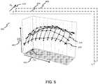
- the efficiency plot 402represents efficiency measured with respect to only two of the potential parameters, output voltage and output current, over which efficiency may be characterized.
- An additional parameter, the input voltageis represented schematically at 418 with frames 404 and 406 representing additional plots just like that shown at 402 but characterized with respect to different values of the input voltage.
- additional sets of plotscould be presented (not shown in Figure 5 ) with respect to different values of device temperature or other parameters.
- the constraints of two-dimensional visualizationlimit the display of the efficiency surface 414 to two dimensions at a time, but is should be appreciated that the efficiency surface is in reality a multidimensional surface that is a function of several parameters that may be varied during the characterization process.
- the power loss of device dis measured for a large number of combinations of V IN , V OUT , I OUT , and T.
- the number of measurements made and the spacing of the data points in parameter spacewill be determined by the desired level of accuracy of the predictive power loss multidimensional surface.
- an uninterruptible power supplymight communicate to the controller that the supply voltage is about to drop, or a power distribution unit (PDU) could communicate status to the controller regarding loads that will be switched on or off or modified, and the controller can make the appropriate adjustments to system parameters to steer the optimally efficient path through these mode changes.
- the controllercan provide status feedback to the external equipment to, for example, constrain operating modes or set switch ramp rates.
Landscapes
- Engineering & Computer Science (AREA)
- Power Engineering (AREA)
- Dc-Dc Converters (AREA)
- Inverter Devices (AREA)
Description
- The present invention relates to power subsystem architectures, and more particularly, to a power subsystem that actively provides energy management and control of subsystem efficiency by using power-loss models of power devices.
- It is well known in the art to use a distributed power subsystem architecture comprising multiple power conversion stages to provide necessary bus voltages for microprocessors, memories, and other electronic devices. A conventional system might operate from an alternating current (AC) primary voltage source that is converted to an intermediate direct current (DC) bus voltage using an isolated AC/DC converter. This intermediate DC bus voltage is then typically distributed throughout the system and converted locally by secondary DC/DC converters to lower voltages matched to the input voltage requirements of system loads. Alternatively, a system might operate from a primary DC bus voltage that is first converted to an intermediate bus voltage by an isolated DC/DC converter. The intermediate voltage is again distributed to secondary regulators or converters to provide the required supply voltages. Examples of conventional systems are depicted in
Figures 1 and 2 which illustrate, respectively, an AC system operating at 230 VAC with an intermediate bus at 12 VDC, and a DC system operating at 48 VDC with an intermediate bus at 12 VDC. - The efficiency of any power converter or regulator is typically a complex function of its operating point, depending on the input voltage, the output voltage, the load current, and the temperature of the device, among other parameters. Thus, the efficiency will typically vary with system activity as loads are switched on or off or run at high or low clock rates and as the system heats up or cools down. Nevertheless, once designed and optimized for a particular operating point, conventional power subsystems are operated statically, regardless of system activity.
- In the system depicted in
Figure 1 , the efficiency of the primary power converter will tend to increase as the input voltage increases, and the efficiency will decrease as the output voltage decreases and as the temperature rises. Similarly, the efficiency of the regulators will tend to increase as the input voltage decreases and as the output voltage rises, and the efficiency will decrease as the temperature rises. The behavior of the system inFigure 2 is similar. Thus, it is clear that the selection of the intermediate voltage will affect the efficiency of the overall system. Lowering the intermediate voltage will reduce the efficiency of the primary converter but raise the efficiency of the secondary regulators. Thus for a given operating state of the system, there is an optimal intermediate voltage that will maximize the overall efficiency of the system. Similarly, although the efficiency of both the primary converter and the secondary regulators decrease as the temperature increases, operating a fan or other active cooling system consumes power and thus reduces system efficiency. Thus, there is also an optimal temperature set point for a given operating state of the system that will maximize power efficiency. - In a typical system, the power subsystem is optimized for a single operating point that would preferably be the operating point at which the system would be found most often. The intermediate voltage and temperature control point are set to this operating point and generally remain fixed, regardless of the actual operating state of the system. However, to reduce total energy consumption, it would be better to dynamically optimize the set points of the power subsystem based on actual system activity. However, in many cases, it is impractical to measure the power loss of a power conversion device directly with enough accuracy to enable effective control. For the most part, this is because measuring the power loss involves taking the difference of two large quantities, the input power and the output power, to arrive at a small power loss measurement. For example, a typical converter might run at an input power of 100W and an output power of 92W, resulting in a power loss of 8W. If the input and output power losses can each be measured with a precision of +/-2%, which is a challenge in itself, the calculation of the power loss will exhibit a large combined error as illustrated below:

- Document
EP 1 569 323 A2 describes a device and method for dynamically optimizing a power converter unit. The power converter unit includes a plurality of parallel modules providing a single output voltage to a single load. Each system may be separately deactivated by a processor to reduce gate power. The processor monitors dynamic parameters affecting the efficiency of the power converter unit, and accordingly determines the number of parallel modules to be activated based on the parameters in order to maximize efficiency. - Document
US 5 532 914 A describes a DC-DC converter apparatus which includes a main converter section, a main control section, a supplemental power supply section, a signal processing section and a supplemental control section. The main converter section coverts a D.C. input into an adequate D.C. output and supplies the converted D.C. output to a load. The supplemental power supply section supplies operating electric power to the main converter section and main control section of the DC-DC converter apparatus. The supplemental control section controls the operative or non-operative state of the supplemental power supply section based on a signal from the signal processing section. The main control section controls the operative or non-operative state of the main converter section in response to the operation or the supplemental power supply section. - Document
US 6 538 412 B1 describes a method for controlling a power drive system. To minimize the energy required for operation of a rail vehicle, in a drive system that has an intermediate circuit converter 1 and a three-phase motor 7 fed by it, the intermediate circuit voltage in theintermediate circuit 12 and/or the magnetic flux in the drive motor 7 are optimized to correspond to the actual operating requirements, including, if necessary, the energy expenditure for the auxiliaries 9 that are provided to cool the components. - Document
US 2007/278986 A1 describes an electric motor drive control system, wherein a voltage command value of a converter is set by executing the step of determining a candidate voltage of a system voltage as a converter output voltage in a voltage range from the minimum necessary voltage corresponding to induction voltage of a motor generator and a maximum output voltage of the converter; the step of estimating power loss at the battery, converter, inverter and motor generator, at each candidate voltage, and calculating total sum of estimated power loss of the overall system; and the step of setting the voltage command value based on the candidate voltage that minimizes the total sum of estimated power losses among the candidate voltages. - Thus, it would be useful to provide a power subsystem that utilizes active control to dynamically optimize design set points in order to maximize subsystem efficiency as system activity changes. And it would be useful to provide a method of characterizing and monitoring the power loss of the power subsystem components in a manner that provides sufficient precision to enable the dynamic optimization of design set points.
- The invention is defined by the features of the independent claims. The dependent claims are directed to preferred embodiments of the invention. The invention provides a power subsystem architecture and a method of characterizing power subsystem components to enable dynamic optimization of design set points to achieve maximum power efficiency across all operating states of a system.
- An embodiment of a power subsystem in accordance with the present invention includes a power bus that may be alternating current (AC) or direct current (DC). A primary power converter converts the primary bus voltage to an intermediate voltage that is distributed to one or more secondary power converters. The secondary power converters may be linear regulators, switching converters, boost converters, buck converters, or any other type of voltage-regulating device known in the art. The one or more secondary converters condition the power that is provided to the system loads.
- In one embodiment of a power subsystem in accordance with the present invention, the individual power devices are adapted to measure temperature, current, voltage, and other operating parameters at the device level and to make the measurement data available over a communications bus such as I2C, RS-485, or any other communication bus known to those skilled in the art. In an alternative embodiment, an external measurement unit is adapted to measure operating parameters of the individual devices. The external measurement unit may comprise a centrally located device or may comprise a collection of individual measurement devices distributed throughout the system. The measured operating parameters may include input and output voltages, input and output currents, and device temperature, among others. The specific transducers and detectors used to make such measurements are well known in the art.
- The power subsystem also includes a controller unit that may include an application-specific integrated circuit (ASIC), a field-programmable gate array (FPGA), a digital signal processing (DSP) device, a microcontroller, a general-purpose processing device, or any other type of processing device. The controller unit includes a communications unit that communicates with the power devices in the system. In an alternative embodiment including an external measurement unit, the communications unit may also communicate with the external measurement unit. The controller unit also includes a memory unit that contains detailed power-loss model data for each of the power components of the system.
- In one embodiment of a power system in accordance with the present invention, the controller unit is a module within the power subsystem, interfaced to the other devices and adapted to collect telemetry from and send commands to the other system devices. In another embodiment, the controller is external to the power subsystem and could comprise, for example, a computer or microprocessor adapted to control the power subsystem. In still another embodiment, the controller could be implemented within one of the power devices itself. For example, the logic circuitry used to operate the primary power converter could also operate as the controller unit.
- In general, the efficiency of a power device is a complex function of a number of operating parameters, such as input and output voltage, current, and temperature, among others. Before the power subsystem is assembled, each of the power devices is independently characterized to measure its power loss, or efficiency, for a large number of different operating conditions. As each operating parameter is varied, the power loss of the device under characterization is measured, and a data point is saved and later written to the memory unit of the power subsystem. The desired level of precision of the power-loss model will dictate how many data points are to be measured and how close their spacing should be. The application for which the power subsystem is to be used will set the required level of precision. Using the measured data points, a function is created that predicts the power loss of the characterized device for an arbitrary combination of operating parameters. Because the measured data consists of a set of discrete data points, it is necessary to interpolate between data points using a linear interpolation model, a cubic spline model, or any other interpolation model known in the art. Similarly, to address operating modes that lie outside of the measured data set, extrapolation methods known in the art may be used.
- The controller unit also contains a processor unit that is adapted to collect data on the operating parameters of the power devices. The processor unit then uses the power-loss models stored in the memory unit along with the operational data to create an estimate of the instantaneous power loss of each of the power components. The processor unit then performs a weighted sum of the power losses of each of the power components to arrive at a goal function. The goal function has a relationship with the total power loss of the system. Indeed, if the weighting factors used in forming the sum of the component power losses are all set to unity, the goal function will be identical to the total system power loss. However, the freedom to set weighting factors provides the system with additional capability to allocate costs to the various components. For example, if it is much harder to cool the primary converter than other components of the system, weighting factors may be selected to reflect this.
- The processor then proceeds to evaluate the effect on the goal function of small changes to the operating parameters of each of the components with the objective of minimizing the goal function and thereby maximizing the efficiency of the subsystem. If the processor determines, for example, that lowering the intermediate bus voltage will result in an improvement of overall subsystem efficiency, it will then command that change to the primary power converter to cause its output voltage to change to the optimal value calculated by the processor. The measurement, calculation, and command cycle will be repeated at a rate set by the demands of the application for which the power subsystem is used. This process results in the dynamic optimization of the efficiency of the subsystem, taking into account changes in loads or operating modes.
- Sometimes, commanding the system to change an intermediate voltage or other parameter might have negative consequences, such as reducing the input voltage to the secondary converters below their recommended levels. To address this, an alternative embodiment of a power subsystem in accordance with the invention also includes a set of subsystem constraint data that is stored in the memory unit. This data may include limits on such parameters as the input voltage, output voltage, temperature, and current, among others, that should not be exceeded in applying a change of state to the system. The constraint data may also change over time. The processor will minimize the goal function subject to the power component constraints such that a commanded change of state will not violate any of the constraints.
- Similarly, some loads that the power subsystem is designed to supply may have limits on current, voltage, temperature, or other parameters that must be kept within an acceptable range. Thus, another embodiment of a power subsystem in accordance with the invention includes a load constraints database that is stored in the memory unit. The minimization of the goal function by the processor will be performed subject to the load constraints such that none of them is violated.
- Another embodiment of a power subsystem in accordance with the present invention includes an active cooling system such as a fan, a heat pump, or other active temperature-control device. Power loss models for the cooling system are developed in the same manner as discussed above and are stored in the memory unit. The processor unit is further adapted to include the cooling system in the evaluation of the goal function in order to maximize subsystem efficiency. For example, many power devices may operate more efficiently at lower temperatures. However, it also takes energy to run the active cooling system. The goal function is used to balance these trades and arrive at the optimal amount of cooling that minimizes the overall subsystem power loss.
- From the foregoing discussion, it should be clear to those skilled in the art that certain advantages of a dynamically optimized power conversion system have been achieved. Further advantages and applications of the invention will become clear to those skilled in the art by examination of the following detailed description of the preferred embodiment. Reference will be made to the attached sheets of drawing that will first be described briefly.
Figures 1 and 2 depict typical distributed power subsystem architectures for an AC and a DC primary bus, respectively;Figure 3 depicts a block diagram of a dynamically optimized power subsystem architecture in accordance with the present invention;Figure 4 depicts an alternate embodiment of a dynamically optimized power subsystem in accordance with the present invention in which an external measurement device is used to collect operational data;Figure 5 illustrates a multidimensional analysis, performed in accordance with the present invention, of the efficiency of a typical power converter module;Figures 6A and 6B depict device constraints used to limit the effective control range of a system in accordance with the present invention; andFigure 7 depicts a flow chart describing the operation of the efficiency optimization procedure in accordance with the present invention.- The invention provides a power subsystem architecture and method of device power-loss characterization and monitoring that enables the dynamic control of operating set points to achieve high efficiency over a wide range of system operating conditions. In the detailed description that follows, like element numerals are used to indicate like elements appearing in one or more of the figures.
- Conventional distributed power subsystem architectures are depicted in the block diagrams of
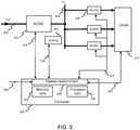
Figures 1 and 2 . InFigure 1 , an AC/DC converter 102 is used to convert a 230-voltprimary AC bus 104 to a 12-voltintermediate DC bus 106. Theintermediate bus 106 is distributed to secondary converters orregulators Figure 2 depicts a similar system that uses a primary DC/DC converter 202 to convert a 48-voltprimary DC bus 204 to a 12-voltintermediate bus 202. In bothFigure 1 and Figure 2 , the voltage of theintermediate bus secondary converters Figure 3 depicts a block diagram of an embodiment of a power subsystem in accordance with the present invention. Aprimary power converter 302 converts theprimary AC bus 304 to anintermediate DC bus 306. It should be appreciated that a primary DC bus and a primary DC/DC converter could be used as well and still fall within the scope and spirit of the invention. Theintermediate bus 306 is distributed to secondary isolated or non-isolated power converters, e.g., 308, or regulators, which may be linear regulators, switching converters, boost converters, buck converters, or any other type of voltage converter or regulator known in the art. Thesecondary power converters 308 condition the voltages used to drive the system loads 310.- A
controller unit 326 comprises acommunications unit 334 for communicating with the power subsystem components, amemory unit 332 for storing power-loss model data, and aprocessor unit 336 for calculating subsystem operating power losses. The controller may comprise an application-specific integrated circuit (ASIC), a field-programmable gate array (FPGA), a digital signal processing (DSP) device, a microcontroller, a general-purpose processing device, or any other processing device known in the art. The embodiment shown inFigure 3 depicts thecontroller 326 as a separate module within the power subsystem with interfaces to the other power subsystem components. For example, thecontroller 326 might be implemented in a microcontroller having internal or external memory and interfaced to the other power subsystem components via an I2C bus. - In an alternative embodiment, the controller may comprise an external device connected to the power subsystem. For example, the controller could be a computer system with its own microprocessor and memory devices that is interfaced to the power subsystem over a communications cable.
- In still another embodiment, the controller may reside within one of the power devices itself. For example, the controller could be implemented within the logic circuitry of the
primary power converter 302 or within one or more of the secondary converters, e.g., 308. Other physical locations of the controller are possible and would also fall within the scope and spirit of the present invention. - The
communications unit 334 communicates with the power devices and other circuit elements via a communications bus such as I2C, RS-485, or any other communications bus known in the art. The communications bus may be point-to-point (e.g., USB) or bussed (e.g, I2C). In the embodiment illustrated inFigure 3 , the components such as theprimary converter 302 and thesecondary converter 308 are assumed to include sensing circuits capable of measuring at least one of temperatures, voltages, and currents and generating digital telemetry including these measurements that is sent back to thecommunications unit 334 over the communications bus, e.g., 318, 324, and 312. For a system using components that do not have such capability, an external measurement device may be used, as discussed below with reference toFigure 4 . - The
communications unit 334 collects measurement data from theprimary converter 302, the secondary converters, e.g., 308 and other system devices, e.g., 320. This measurement data may comprise, among other items, input voltage, output voltage, current, and temperature data for each of the respective power subsystem components. Acooling circuit 320 provides active cooling of the power system components and may comprise a fan, an active heat pump, or any other active cooling device known in the art. Operational parameters, including temperature and current consumed by the cooling device are also returned to thecommunications unit 334.System constraints 328 and, optionally,load constraints 330 may also be sent to thecommunications unit 334. The nature of this constraint data is described more fully below with reference toFigures 6A and 6B . - The
controller 326 makes use of the measurement data from the power system components and theconstraints data Figure 5 . The controller sends control commands to theprimary converter 302, to thesecondary converters 308, and to thecooling system 320. The power subsystem components respond by changing their operating set points in accordance with the commanded adjustments in order to maximize power system efficiency for the current temperature and system loads. Figure 4 presents an alternative embodiment of a power subsystem in accordance with the present invention. In this embodiment, the secondary DC/DC converters, e.g., 362, are assumed not to have the capability of measuring and reporting voltage and current telemetry themselves. Thus, anexternal measurement circuit 366, employing sensors well known in the art, is used to gatheranalog measurements 364 and create digital telemetry that is then sent to thecommunications unit 380 over acommunications bus 368. Theexternal measurement unit 366 may be a centralized unit as shown inFigure 4 , or may comprise several distributed units that are located near the devices to be measured. Devices that are capable of generating their own digital telemetry may communicate directly with thecommunications unit 380, such as theprimary converter 352, and thecooling unit 358 depicted in this embodiment. Any combination of devices that interface with anexternal measurement unit 366 or that develop their own telemetry may be used in accordance with the present invention.- Calculating the instantaneous power losses of the
primary converter 320 and the secondary converters 308 (seeFigure 3 ) is difficult because of the compounding nature of measurement errors when a small quantity (the power loss) is determined from the difference of two large quantities (the input power and the output power). To circumvent this problem, a power system operating in accordance with the present invention makes use of characterization data collected for each power subsystem component to enable calculation of the overall system efficiency from measurements of several performance parameters. Thecontroller 326 includes amemory unit 332 that is adapted to store power-loss-model characterization data for each of the components of the power subsystem. Aprocessor unit 336 combines the measured data with the previously gathered characterization data in order to obtain accurate estimates of power loss that are then used to calculate operating efficiency. - The efficiency of a power conversion device is a complex function of several parameters, including input and output voltage, input and output current, and temperature, among others. Each component of a power subsystem in accordance with the present invention is characterized to measure its power loss across multiple values of multiple operating parameters. Although this process can be time consuming, it need be performed only once to gather characterization data that can be stored in tabular form in the
memory unit 332.Figure 5 presents agraphical plot 402 of theefficiency 408 of a typical power converter component with respect to two of these dimensions, theoutput voltage 412 and theoutput current 410. Here, the efficiency of the device being characterized is plotted along thevertical axis 408, as a function of the output voltage, plotted along anorthogonal axis 412, and the output current, plotted along the otherorthogonal axis 410. Each measured point is represented by a filled circle, e.g., 416. These points are connected to form acomplex surface 414 representing the efficiency with respect to these two parameters. The preferred method of interpolating between the measured points to generate this complex surface is to use a multidimensional natural cubic spline, well known to those skilled in the art. A simpler linear interpolation model could also be used at the cost of some loss of accuracy. Similar techniques can be used to extrapolate beyond the measured data, although the greatest accuracy will be achieved by collecting measured data points that envelope all of the anticipated operating modes of the component when installed in the system. Of course, other methods, well known in the art, of interpolating between and extrapolating beyond measured data may be used in accordance with the present invention. - The
efficiency plot 402 represents efficiency measured with respect to only two of the potential parameters, output voltage and output current, over which efficiency may be characterized. An additional parameter, the input voltage, is represented schematically at 418 withframes Figure 5 ) with respect to different values of device temperature or other parameters. The constraints of two-dimensional visualization limit the display of theefficiency surface 414 to two dimensions at a time, but is should be appreciated that the efficiency surface is in reality a multidimensional surface that is a function of several parameters that may be varied during the characterization process. For the purposes of the following discussion, it will be assumed that the efficiency is characterized with respect to the input voltage, VIN, the output voltage, VOUT, the output current IOUT, and the device temperature T, because these are the parameters that will generally produce the largest effect on device efficiency. However, it should be appreciated that fewer or additional characterization parameters may be used to characterize a device in accordance with the present invention. Although the foregoing discussion has focused on the use of the power-loss data to calculate device efficiency, the invention is not limited to applications that use efficiency calculations. The power-loss data can also be used directly to characterize a device in accordance with the present invention. - In a process in accordance with the present invention, the power loss of device d, represented by Pd, is measured for a large number of combinations of VIN, VOUT, IOUT, and T. The number of measurements made and the spacing of the data points in parameter space will be determined by the desired level of accuracy of the predictive power loss multidimensional surface. This surface may be represented as:

Figure 3 ) and enables theprocessor unit 336 of the controller to calculate a predicted power loss for device d for any set of measured parameters returned from the device to the measurement unit, e.g., by path 322. Further, theprocessor unit 336 is able to calculate a predicted change in the power loss of device d if one of the input parameters were to change by a small amount. For example, if the input voltage were to increase by ΔVIN, the controller would be able to calculate the predicted change in power loss for device d as follows:
- If the
processor unit 336 calculates that ΔPd is negative, it knows that an increase of ΔVIN for this device will cause a drop in the power loss, or increase in efficiency, so that this would be a preferred operating state for this device. Similarly, thememory unit 332 of thecontroller 326 maintains power-loss models for all of the devices in the system and actively retrieves data on the operating state of each device via thecommunications unit 334, as illustrated schematically inFigure 3 at 318, 324, and 312. Of course, the controller could also use a communication bus to gather this data rather than the point-to-point connections shown inFigure 3 . The voltages, currents, and temperatures at each of the devices can be measured by standard instrumentation circuits well known to those skilled in the art. - By summing the power losses of the individual components used to construct the power subsystem, the power losses of the full subsystem can be calculated by the
processor unit 336 as follows:
Figure 3 , which comprises one AC/DC converter and three secondary DC/DC converters, the power loss of the system can be expressed as follows:

- Again, if this calculated change in power loss is negative, the controller will have determined that an increase in intermediate bus voltage will improve the efficiency of the system for this particular set of operating parameters. The
controller 326 will thus command a change in the intermediate bus voltage via thecommunications unit 334, e.g., overpath 318. - However, before commanding such a change in an operating parameter, the controller first must determine whether the change is valid. For example, reducing the intermediate bus voltage below a certain point may take one of the
secondary regulators 308 out of its specified operating range or reduce its headroom below recommended levels. Furthermore, dropping the intermediate bus voltage will increase the output current of theprimary converter 302 and could place the device into an unsafe operating mode or increase its temperature beyond specified limits. Thus, thememory unit 332 of thecontroller 326 also contains tables of device constraints against which it must check all potential operating parameter adjustments. Examples of such device constraints are provided inFigures 6A and 6B . Figure 6A depicts a typical constraint set for a power converter device. Here, asafe operating area 506 is displayed as a function ofinput voltage 504 andoutput voltage 502. From the figure it is evident that the value of the input voltage at which the device is operated should not exceed a maximum value depicted at 514. Similarly, it should not be operated at an input voltage less than the value depicted at 510. Further, if aspecific output voltage 516 is required, the input voltage cannot be reduced below thevoltage level 512, which would be equivalent to overriding the minimum voltage requirement at 510.Figure 6B depicts a similar constraint operating on the output current and temperature of a typical power converter device. Here, thesafe operating area 554 defines a region oftemperature 552 and output current 550 parameter space beyond which the device should not be operated. The safe region defines a maximum temperature at 562 and a maximum current at 556, but also illustrates that the maximum current may depend on temperature. For example at the temperature indicated at 560, the maximum allowable current is indicated at 558 and is lower than the absolute maximum at 556.- The controller takes into account the constraint files for all of the subsystem components before commanding a change that could potentially cause these limits to be exceeded. At the overall subsystem level, there may be additional constraints that the controller needs to consider. For example, in a given system, it may be very difficult to cool the primary AC/DC converter, so it may be advantageous at the system level to place a larger weight on the AC/DC converter power loss as compared to the other devices. This would result in the system's reaching an optimized operating point with lower AC/DC converter losses to minimize the temperature rise in this device. Such a weighting of the power loss contributions of the constituent devices of a power subsystem can be achieved by the introduction of a weighting coefficient, Ki, multiplying the power loss characterization function for device i. The sum of the weighted power loss functions, then, would no longer equal the total system power loss, but would instead represent a more generalized goal function, GF, for the system that the controller would seek to minimize.

- Additional constraints might come from external equipment. For example, an uninterruptible power supply (UPS) might communicate to the controller that the supply voltage is about to drop, or a power distribution unit (PDU) could communicate status to the controller regarding loads that will be switched on or off or modified, and the controller can make the appropriate adjustments to system parameters to steer the optimally efficient path through these mode changes. In addition, the controller can provide status feedback to the external equipment to, for example, constrain operating modes or set switch ramp rates.
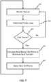
Figure 7 depicts a flow chart of a method of performing the optimization process described above in accordance with the present invention. Atstep 602, the controller collects data from a target device, the data may comprise input and output voltage, output current, device temperature, or any other operating parameters for which characterization data has been obtained previously. Atstep 604, the controller determines the power loss of the target device using the stored power-loss model and the measured parameters collected atstep 602. Atstep 606, the controller evaluates whether it has obtained data from all of the devices in the system. If not, it returns to step 602 for the next device and continues until it has calculated power losses for all of the devices in the system. At that point, the controller proceeds to step 608, at which the overall goal function for the system is calculated. As discussed previously, the goal function may be equal to the overall system power loss or may be a more generalized sum of weighted power losses. The controller then loads device and system constraint data and calculates new subsystem set points to minimize the goal function subject to the device and system constraints. The minimization process may be performed by any of the methods well known to those skilled in the art, such as a steepest descent method obtained by calculating partial derivatives with respect to each of the control parameters. The controller then proceeds to step 610, at which the new set points are applied to the system, improving the overall efficiency. The controller then returns to step 602 to repeat the entire process such that the overall efficiency of the system is iteratively improved, and so that it responds to changes in load requirements, temperature, etc., on a continuous basis. The rate at which this optimization process runs can be selected based on the system requirements, which would include the temperature stability of the system and the character of the loads, among other considerations.- While the description of the optimization process provided above is largely focused on controlling the intermediate voltage of a typical power subsystem, the process can be applied to any parameter that affects the power losses of a power subsystem. For example, this process may be used to control the speed of a cooling fan to balance the increase in efficiency resulting from lower temperature devices with the increase in power loss that accompanies an increase in fan-drive current. Similarly, this process could be used to control the pulse-width modulation (PWM) switching frequency of the converters to maximize efficiency.
- Thus, a power subsystem incorporating a controller in accordance with the present invention that uses power loss models and measured device performance data to actively control design set points results in highly optimized system performance and efficiency. The invention is further defined by the following claims.


Claims (15)
- A power subsystem comprising:an active cooling system (320);a primary power converter (302);at least one secondary power converter (308) operatively connected to the primary power converter (302);wherein the power subsystem is adapted to measure:at least one cooling operating parameter of the cooling system;at least one primary operating parameter of the primary power converter (302); andat least one secondary operating parameter of the at least one secondary power converter (308); anda controller (326) connected to the cooling system (320), the primary power converter (302), and to the at least one secondary converter, whereinthe controller comprises a communication unit (334) adapted to receive the at least one cooling operating parameter, the at least one primary operating parameter and the at least one secondary operating parameter measured by the power subsystem and to send at least one control command to at least one of the cooling system, the primary power converter (302) and the at least one secondary power converter (308);the primary converter (302) is adapted to convert a primary voltage to an intermediate voltage and to distribute the intermediate voltage to the at least one secondary power converter (308); andcharacterized in thatthe controller (326) further comprises:a memory unit (332) adapted to store cooling power-loss model associated with the cooling system (320), a primary power-loss model associated with the primary power converter (302), and at least one secondary power-loss model associated with the at least one secondary power converter (308); anda processor unit (336) adapted to:calculate a goal function from the cooling power-loss model, the primary power-loss model, the at least one secondary power-loss model, the cooling operating parameter, the at least one primary operating parameter and the at least one secondary operating parameter; andcalculate a change of state of at least one of the cooling system, the primary power converter (302) and the at least one secondary power converter (308) such that the goal function is minimized, andgenerate the at least one control command based on the change of state;the cooling system, the primary power converter and the at least one secondary power converter are adapted to change their operating set points based on the at least one control command received from the communication unit (334).
- The power subsystem of Claim 1, wherein:the at least one primary operating parameter of the primary power converter (302) comprises at least one of a primary input voltage, a primary output voltage, a primary output current, and a primary temperature of the primary power converter (302); andthe at least one secondary operating parameter of the at least one secondary power converter (308) comprises at least one of a secondary input voltage, a secondary output voltage, a secondary output current, and a secondary temperature of the at least one secondary power converter (308).
- The power subsystem of Claim 1, wherein the goal function comprises a weighted sum of power losses associated with corresponding ones of the primary power converter (302) and the at least one secondary power converter (308).
- The power subsystem of Claim 3, wherein the goal function is equal to a total power loss of the power subsystem.
- The power subsystem of Claim 1, wherein:
the at least one cooling operating parameter is at least one of a voltage, a current, and a temperature associated with the active cooling system (320). - The power subsystem of Claim 1, wherein the primary power converter comprises at least one of an AC/DC converter and a DC/DC converter.
- The power subsystem of Claim 1, wherein the at least one secondary power converter (308) comprises at least one of a switching converter, a buck converter, a boost converter, and a linear regulator.
- The power subsystem of Claim 1, wherein the controller (326) comprises at least one of an application-specific integrated circuit (ASIC), a field-programmable gate array (FPGA), a digital signal processing (DSP) device, a microcontroller, and a general-purpose processing device.
- The power subsystem of Claim 1, wherein the controller (326) comprises an external processing device connected to the power subsystem.
- The power subsystem of Claim 1, wherein the controller (326) comprises logic circuits residing within at least one of the primary power converter (302) and the at least one secondary power converter (308).
- The power subsystem of Claim 1, wherein at least one of the primary power converter (302) and the at least one secondary power converter (308) is adapted to measure at least one of the at least one primary operating parameter and the at least one secondary operating parameter.
- The power subsystem of Claim 1, further comprising a measurement unit adapted to measure the at least one primary operating parameter and the at least one secondary operating parameter.
- The power subsystem of Claim 1, wherein the controller (326) is further adapted to store subsystem constraints data comprising at least one of:a maximum input voltage, a minimum input voltage, a maximum output voltage, a minimum output voltage, a maximum temperature, a maximum current, and a minimum current of the primary power converter (302); and at least one of:a maximum input voltage, a minimum input voltage, a maximum output voltage, a minimum output voltage, a maximum temperature, a maximum current, and a minimum current of the at least one secondary power converter (308);wherein the processor unit (336) is further adapted to calculate a change of state of at least one of the primary power converter (302) and the at least one secondary power converter (308) such that the goal function is minimized and such that none of the subsystem constraints is violated.
- The power subsystem of Claim 1, wherein the at least one secondary power converter (308) is connected to at least one load (310); and
wherein the controller (326) is further adapted to store load constraints data associated with the at least one load (310) comprising at least one of:a maximum voltage, a minimum voltage, a maximum current, a minimum current, and a maximum temperature for the at least one load (310);wherein the processor unit (336) is further adapted to calculate a change of state of at least one of the primary power converter (302) and the at least one secondary power converter (308) such that the goal function is minimized and such that none of the load constraints is violated. - A method for dynamically optimizing efficiency of a power subsystem containing a plurality of power devices, the plurality of power devices including an active cooling system (320), a primary power converter (302) and at least one secondary power converter (308), the primary converter (302) converting a primary voltage to an intermediate voltage and distributing the intermediate voltage to the at least one secondary power converter (308), the method beingcharacterized by the steps of:creating power-loss models of each of the plurality of power devices;measuring operating parameters of each of the plurality of power devices;calculating the power loss of each of the plurality of power devices from the measured operating parameters and the power-loss models for each of the plurality of power devices;calculating a goal function by forming a weighted sum of the power losses calculated for each of the plurality of power devices;calculating a change of state of the operating parameters of ones of the plurality of power devices such that the goal function is minimized;commanding the calculated change of state to at least one of the plurality of power devices;changing at least one operating set point of the power devices based on the commanded calculated change of state; andrepeating the measuring, calculating, and commanding steps on a periodic basis.
Applications Claiming Priority (2)
| Application Number | Priority Date | Filing Date | Title |
|---|---|---|---|
| US12/127,726US8179705B2 (en) | 2008-05-27 | 2008-05-27 | Apparatus and method of optimizing power system efficiency using a power loss model |
| PCT/US2009/043817WO2009146259A1 (en) | 2008-05-27 | 2009-05-13 | Apparatus and method of optimizing power system efficiency using a power loss model |
Publications (3)
| Publication Number | Publication Date |
|---|---|
| EP2289141A1 EP2289141A1 (en) | 2011-03-02 |
| EP2289141A4 EP2289141A4 (en) | 2013-12-04 |
| EP2289141B1true EP2289141B1 (en) | 2020-09-30 |
Family
ID=41377528
Family Applications (1)
| Application Number | Title | Priority Date | Filing Date |
|---|---|---|---|
| EP09755621.1ANot-in-forceEP2289141B1 (en) | 2008-05-27 | 2009-05-13 | Apparatus and method of optimizing power system efficiency using a power loss model |
Country Status (6)
| Country | Link |
|---|---|
| US (1) | US8179705B2 (en) |
| EP (1) | EP2289141B1 (en) |
| JP (1) | JP5462868B2 (en) |
| KR (1) | KR101300449B1 (en) |
| CN (1) | CN102047522B (en) |
| WO (1) | WO2009146259A1 (en) |
Families Citing this family (492)
| Publication number | Priority date | Publication date | Assignee | Title |
|---|---|---|---|---|
| US20070084897A1 (en) | 2003-05-20 | 2007-04-19 | Shelton Frederick E Iv | Articulating surgical stapling instrument incorporating a two-piece e-beam firing mechanism |
| US9060770B2 (en) | 2003-05-20 | 2015-06-23 | Ethicon Endo-Surgery, Inc. | Robotically-driven surgical instrument with E-beam driver |
| US8215531B2 (en) | 2004-07-28 | 2012-07-10 | Ethicon Endo-Surgery, Inc. | Surgical stapling instrument having a medical substance dispenser |
| US11998198B2 (en) | 2004-07-28 | 2024-06-04 | Cilag Gmbh International | Surgical stapling instrument incorporating a two-piece E-beam firing mechanism |
| US9072535B2 (en) | 2011-05-27 | 2015-07-07 | Ethicon Endo-Surgery, Inc. | Surgical stapling instruments with rotatable staple deployment arrangements |
| US11890012B2 (en) | 2004-07-28 | 2024-02-06 | Cilag Gmbh International | Staple cartridge comprising cartridge body and attached support |
| US9237891B2 (en) | 2005-08-31 | 2016-01-19 | Ethicon Endo-Surgery, Inc. | Robotically-controlled surgical stapling devices that produce formed staples having different lengths |
| US10159482B2 (en) | 2005-08-31 | 2018-12-25 | Ethicon Llc | Fastener cartridge assembly comprising a fixed anvil and different staple heights |
| US7934630B2 (en) | 2005-08-31 | 2011-05-03 | Ethicon Endo-Surgery, Inc. | Staple cartridges for forming staples having differing formed staple heights |
| US11484312B2 (en) | 2005-08-31 | 2022-11-01 | Cilag Gmbh International | Staple cartridge comprising a staple driver arrangement |
| US11246590B2 (en) | 2005-08-31 | 2022-02-15 | Cilag Gmbh International | Staple cartridge including staple drivers having different unfired heights |
| US7669746B2 (en) | 2005-08-31 | 2010-03-02 | Ethicon Endo-Surgery, Inc. | Staple cartridges for forming staples having differing formed staple heights |
| US20070106317A1 (en) | 2005-11-09 | 2007-05-10 | Shelton Frederick E Iv | Hydraulically and electrically actuated articulation joints for surgical instruments |
| US11224427B2 (en) | 2006-01-31 | 2022-01-18 | Cilag Gmbh International | Surgical stapling system including a console and retraction assembly |
| US11278279B2 (en) | 2006-01-31 | 2022-03-22 | Cilag Gmbh International | Surgical instrument assembly |
| US20120292367A1 (en) | 2006-01-31 | 2012-11-22 | Ethicon Endo-Surgery, Inc. | Robotically-controlled end effector |
| US8708213B2 (en) | 2006-01-31 | 2014-04-29 | Ethicon Endo-Surgery, Inc. | Surgical instrument having a feedback system |
| US20110295295A1 (en) | 2006-01-31 | 2011-12-01 | Ethicon Endo-Surgery, Inc. | Robotically-controlled surgical instrument having recording capabilities |
| US7845537B2 (en) | 2006-01-31 | 2010-12-07 | Ethicon Endo-Surgery, Inc. | Surgical instrument having recording capabilities |
| US8186555B2 (en) | 2006-01-31 | 2012-05-29 | Ethicon Endo-Surgery, Inc. | Motor-driven surgical cutting and fastening instrument with mechanical closure system |
| US20110024477A1 (en) | 2009-02-06 | 2011-02-03 | Hall Steven G | Driven Surgical Stapler Improvements |
| US11793518B2 (en) | 2006-01-31 | 2023-10-24 | Cilag Gmbh International | Powered surgical instruments with firing system lockout arrangements |
| US8820603B2 (en) | 2006-01-31 | 2014-09-02 | Ethicon Endo-Surgery, Inc. | Accessing data stored in a memory of a surgical instrument |
| US7753904B2 (en) | 2006-01-31 | 2010-07-13 | Ethicon Endo-Surgery, Inc. | Endoscopic surgical instrument with a handle that can articulate with respect to the shaft |
| US8992422B2 (en) | 2006-03-23 | 2015-03-31 | Ethicon Endo-Surgery, Inc. | Robotically-controlled endoscopic accessory channel |
| US8236010B2 (en) | 2006-03-23 | 2012-08-07 | Ethicon Endo-Surgery, Inc. | Surgical fastener and cutter with mimicking end effector |
| US8322455B2 (en) | 2006-06-27 | 2012-12-04 | Ethicon Endo-Surgery, Inc. | Manually driven surgical cutting and fastening instrument |
| US10568652B2 (en) | 2006-09-29 | 2020-02-25 | Ethicon Llc | Surgical staples having attached drivers of different heights and stapling instruments for deploying the same |
| US7506791B2 (en) | 2006-09-29 | 2009-03-24 | Ethicon Endo-Surgery, Inc. | Surgical stapling instrument with mechanical mechanism for limiting maximum tissue compression |
| US11980366B2 (en) | 2006-10-03 | 2024-05-14 | Cilag Gmbh International | Surgical instrument |
| US8632535B2 (en) | 2007-01-10 | 2014-01-21 | Ethicon Endo-Surgery, Inc. | Interlock and surgical instrument including same |
| US8684253B2 (en) | 2007-01-10 | 2014-04-01 | Ethicon Endo-Surgery, Inc. | Surgical instrument with wireless communication between a control unit of a robotic system and remote sensor |
| US11291441B2 (en) | 2007-01-10 | 2022-04-05 | Cilag Gmbh International | Surgical instrument with wireless communication between control unit and remote sensor |
| US8652120B2 (en) | 2007-01-10 | 2014-02-18 | Ethicon Endo-Surgery, Inc. | Surgical instrument with wireless communication between control unit and sensor transponders |
| US20080169333A1 (en) | 2007-01-11 | 2008-07-17 | Shelton Frederick E | Surgical stapler end effector with tapered distal end |
| US11039836B2 (en) | 2007-01-11 | 2021-06-22 | Cilag Gmbh International | Staple cartridge for use with a surgical stapling instrument |
| US7673782B2 (en) | 2007-03-15 | 2010-03-09 | Ethicon Endo-Surgery, Inc. | Surgical stapling instrument having a releasable buttress material |
| US8893946B2 (en) | 2007-03-28 | 2014-11-25 | Ethicon Endo-Surgery, Inc. | Laparoscopic tissue thickness and clamp load measuring devices |
| US11564682B2 (en) | 2007-06-04 | 2023-01-31 | Cilag Gmbh International | Surgical stapler device |
| US8931682B2 (en) | 2007-06-04 | 2015-01-13 | Ethicon Endo-Surgery, Inc. | Robotically-controlled shaft based rotary drive systems for surgical instruments |
| US7753245B2 (en) | 2007-06-22 | 2010-07-13 | Ethicon Endo-Surgery, Inc. | Surgical stapling instruments |
| US11849941B2 (en) | 2007-06-29 | 2023-12-26 | Cilag Gmbh International | Staple cartridge having staple cavities extending at a transverse angle relative to a longitudinal cartridge axis |
| US8636736B2 (en) | 2008-02-14 | 2014-01-28 | Ethicon Endo-Surgery, Inc. | Motorized surgical cutting and fastening instrument |
| US9179912B2 (en) | 2008-02-14 | 2015-11-10 | Ethicon Endo-Surgery, Inc. | Robotically-controlled motorized surgical cutting and fastening instrument |
| US11986183B2 (en) | 2008-02-14 | 2024-05-21 | Cilag Gmbh International | Surgical cutting and fastening instrument comprising a plurality of sensors to measure an electrical parameter |
| US8573465B2 (en) | 2008-02-14 | 2013-11-05 | Ethicon Endo-Surgery, Inc. | Robotically-controlled surgical end effector system with rotary actuated closure systems |
| JP5410110B2 (en) | 2008-02-14 | 2014-02-05 | エシコン・エンド−サージェリィ・インコーポレイテッド | Surgical cutting / fixing instrument with RF electrode |
| US7866527B2 (en) | 2008-02-14 | 2011-01-11 | Ethicon Endo-Surgery, Inc. | Surgical stapling apparatus with interlockable firing system |
| US8758391B2 (en) | 2008-02-14 | 2014-06-24 | Ethicon Endo-Surgery, Inc. | Interchangeable tools for surgical instruments |
| US7819298B2 (en) | 2008-02-14 | 2010-10-26 | Ethicon Endo-Surgery, Inc. | Surgical stapling apparatus with control features operable with one hand |
| US11272927B2 (en) | 2008-02-15 | 2022-03-15 | Cilag Gmbh International | Layer arrangements for surgical staple cartridges |
| US9585657B2 (en) | 2008-02-15 | 2017-03-07 | Ethicon Endo-Surgery, Llc | Actuator for releasing a layer of material from a surgical end effector |
| US8097967B2 (en) | 2008-06-30 | 2012-01-17 | Demand Energy Networks, Inc. | Energy systems, energy devices, energy utilization methods, and energy transfer methods |
| US8253395B2 (en)* | 2008-08-07 | 2012-08-28 | Microsemi Corporation | Bus voltage optimizer for switched power converter |
| DE102008039334B4 (en)* | 2008-08-22 | 2016-01-14 | Airbus Defence and Space GmbH | Method and device for optimized energy management |
| US11648005B2 (en) | 2008-09-23 | 2023-05-16 | Cilag Gmbh International | Robotically-controlled motorized surgical instrument with an end effector |
| US9005230B2 (en) | 2008-09-23 | 2015-04-14 | Ethicon Endo-Surgery, Inc. | Motorized surgical instrument |
| US8210411B2 (en) | 2008-09-23 | 2012-07-03 | Ethicon Endo-Surgery, Inc. | Motor-driven surgical cutting instrument |
| US9386983B2 (en) | 2008-09-23 | 2016-07-12 | Ethicon Endo-Surgery, Llc | Robotically-controlled motorized surgical instrument |
| US8608045B2 (en) | 2008-10-10 | 2013-12-17 | Ethicon Endo-Sugery, Inc. | Powered surgical cutting and stapling apparatus with manually retractable firing system |
| US8582330B2 (en)* | 2009-01-23 | 2013-11-12 | Lockheed Martin Corporation | High voltage and frequency distributed power system |
| US8517239B2 (en) | 2009-02-05 | 2013-08-27 | Ethicon Endo-Surgery, Inc. | Surgical stapling instrument comprising a magnetic element driver |
| RU2525225C2 (en) | 2009-02-06 | 2014-08-10 | Этикон Эндо-Серджери, Инк. | Improvement of drive surgical suturing instrument |
| US8444036B2 (en) | 2009-02-06 | 2013-05-21 | Ethicon Endo-Surgery, Inc. | Motor driven surgical fastener device with mechanisms for adjusting a tissue gap within the end effector |
| US9231439B2 (en)* | 2009-03-27 | 2016-01-05 | Schneider Electric It Corporation | System and method for estimating an efficiency of a power device |
| WO2010149205A1 (en)* | 2009-06-23 | 2010-12-29 | Telefonaktiebolaget Lm Ericsson (Publ) | Intermediate bus architecture power supply controller |
| US10110003B2 (en)* | 2009-11-24 | 2018-10-23 | James R. Stalker | Energy optimization system |
| US8220688B2 (en) | 2009-12-24 | 2012-07-17 | Ethicon Endo-Surgery, Inc. | Motor-driven surgical cutting instrument with electric actuator directional control assembly |
| US8851354B2 (en) | 2009-12-24 | 2014-10-07 | Ethicon Endo-Surgery, Inc. | Surgical cutting instrument that analyzes tissue thickness |
| US8391036B2 (en)* | 2009-12-29 | 2013-03-05 | International Business Machines Corporation | Selective enablement of power supply sections for improving efficiency |
| CN102201699A (en)* | 2010-03-23 | 2011-09-28 | 百富(澳门离岸商业服务)有限公司 | Distributed power supply system with digital power supply manager for providing digital closed loop power control |
| WO2012007055A1 (en)* | 2010-07-16 | 2012-01-19 | Telefonaktiebolaget Lm Ericsson (Publ) | Intermediate bus architecture power supply controller |
| US8783543B2 (en) | 2010-07-30 | 2014-07-22 | Ethicon Endo-Surgery, Inc. | Tissue acquisition arrangements and methods for surgical stapling devices |
| US20120049634A1 (en)* | 2010-08-24 | 2012-03-01 | Samuel Martin Babb | Power conversion using dc and ac current sharing to produce an ac distribution output |
| DE102010044724A1 (en)* | 2010-09-08 | 2012-03-08 | EnBW Energie Baden-Württemberg AG | Method for improved loss energy forecasting in a transmission network |
| US9277919B2 (en) | 2010-09-30 | 2016-03-08 | Ethicon Endo-Surgery, Llc | Tissue thickness compensator comprising fibers to produce a resilient load |
| US11812965B2 (en) | 2010-09-30 | 2023-11-14 | Cilag Gmbh International | Layer of material for a surgical end effector |
| US9301753B2 (en) | 2010-09-30 | 2016-04-05 | Ethicon Endo-Surgery, Llc | Expandable tissue thickness compensator |
| US9016542B2 (en) | 2010-09-30 | 2015-04-28 | Ethicon Endo-Surgery, Inc. | Staple cartridge comprising compressible distortion resistant components |
| US9055941B2 (en) | 2011-09-23 | 2015-06-16 | Ethicon Endo-Surgery, Inc. | Staple cartridge including collapsible deck |
| US9364233B2 (en) | 2010-09-30 | 2016-06-14 | Ethicon Endo-Surgery, Llc | Tissue thickness compensators for circular surgical staplers |
| US9220501B2 (en) | 2010-09-30 | 2015-12-29 | Ethicon Endo-Surgery, Inc. | Tissue thickness compensators |
| US11298125B2 (en) | 2010-09-30 | 2022-04-12 | Cilag Gmbh International | Tissue stapler having a thickness compensator |
| US12213666B2 (en) | 2010-09-30 | 2025-02-04 | Cilag Gmbh International | Tissue thickness compensator comprising layers |
| US10945731B2 (en) | 2010-09-30 | 2021-03-16 | Ethicon Llc | Tissue thickness compensator comprising controlled release and expansion |
| US11925354B2 (en) | 2010-09-30 | 2024-03-12 | Cilag Gmbh International | Staple cartridge comprising staples positioned within a compressible portion thereof |
| US9351730B2 (en) | 2011-04-29 | 2016-05-31 | Ethicon Endo-Surgery, Llc | Tissue thickness compensator comprising channels |
| US9629814B2 (en) | 2010-09-30 | 2017-04-25 | Ethicon Endo-Surgery, Llc | Tissue thickness compensator configured to redistribute compressive forces |
| US9788834B2 (en) | 2010-09-30 | 2017-10-17 | Ethicon Llc | Layer comprising deployable attachment members |
| US9386988B2 (en) | 2010-09-30 | 2016-07-12 | Ethicon End-Surgery, LLC | Retainer assembly including a tissue thickness compensator |
| RU2013119928A (en) | 2010-09-30 | 2014-11-10 | Этикон Эндо-Серджери, Инк. | A STAPLING SYSTEM CONTAINING A RETAINING MATRIX AND A LEVELING MATRIX |
| US9232941B2 (en) | 2010-09-30 | 2016-01-12 | Ethicon Endo-Surgery, Inc. | Tissue thickness compensator comprising a reservoir |
| US8695866B2 (en) | 2010-10-01 | 2014-04-15 | Ethicon Endo-Surgery, Inc. | Surgical instrument having a power control circuit |
| JP2012165615A (en)* | 2011-02-09 | 2012-08-30 | Ntt Data Intellilink Corp | Power supply system |
| EP2700137B1 (en)* | 2011-04-20 | 2017-06-07 | Telefonaktiebolaget LM Ericsson (publ) | Control of dynamic bus voltage in an intermediate bus architecture power system |
| AU2012250197B2 (en) | 2011-04-29 | 2017-08-10 | Ethicon Endo-Surgery, Inc. | Staple cartridge comprising staples positioned within a compressible portion thereof |
| US11207064B2 (en) | 2011-05-27 | 2021-12-28 | Cilag Gmbh International | Automated end effector component reloading system for use with a robotic system |
| US9525285B2 (en) | 2011-06-13 | 2016-12-20 | Demand Energy Networks, Inc. | Energy systems and energy supply methods |
| CN102331562B (en)* | 2011-08-31 | 2013-07-24 | 华南理工大学 | Method for forecasting efficiency of electrochemical high-frequency switching power supply |
| US9050084B2 (en) | 2011-09-23 | 2015-06-09 | Ethicon Endo-Surgery, Inc. | Staple cartridge including collapsible deck arrangement |
| TW201328118A (en)* | 2011-12-28 | 2013-07-01 | Hon Hai Prec Ind Co Ltd | Uninterruptible power supply system |
| US9044230B2 (en) | 2012-02-13 | 2015-06-02 | Ethicon Endo-Surgery, Inc. | Surgical cutting and fastening instrument with apparatus for determining cartridge and firing motion status |
| BR112014024098B1 (en) | 2012-03-28 | 2021-05-25 | Ethicon Endo-Surgery, Inc. | staple cartridge |
| JP6224070B2 (en) | 2012-03-28 | 2017-11-01 | エシコン・エンド−サージェリィ・インコーポレイテッドEthicon Endo−Surgery,Inc. | Retainer assembly including tissue thickness compensator |
| MX358135B (en) | 2012-03-28 | 2018-08-06 | Ethicon Endo Surgery Inc | Tissue thickness compensator comprising a plurality of layers. |
| US9101358B2 (en) | 2012-06-15 | 2015-08-11 | Ethicon Endo-Surgery, Inc. | Articulatable surgical instrument comprising a firing drive |
| US9408606B2 (en) | 2012-06-28 | 2016-08-09 | Ethicon Endo-Surgery, Llc | Robotically powered surgical device with manually-actuatable reversing system |
| US20140005718A1 (en) | 2012-06-28 | 2014-01-02 | Ethicon Endo-Surgery, Inc. | Multi-functional powered surgical device with external dissection features |
| JP6290201B2 (en) | 2012-06-28 | 2018-03-07 | エシコン・エンド−サージェリィ・インコーポレイテッドEthicon Endo−Surgery,Inc. | Lockout for empty clip cartridge |
| US9282974B2 (en) | 2012-06-28 | 2016-03-15 | Ethicon Endo-Surgery, Llc | Empty clip cartridge lockout |
| US20140001231A1 (en) | 2012-06-28 | 2014-01-02 | Ethicon Endo-Surgery, Inc. | Firing system lockout arrangements for surgical instruments |
| US9289256B2 (en) | 2012-06-28 | 2016-03-22 | Ethicon Endo-Surgery, Llc | Surgical end effectors having angled tissue-contacting surfaces |
| US12383267B2 (en) | 2012-06-28 | 2025-08-12 | Cilag Gmbh International | Robotically powered surgical device with manually-actuatable reversing system |
| US11278284B2 (en) | 2012-06-28 | 2022-03-22 | Cilag Gmbh International | Rotary drive arrangements for surgical instruments |
| BR112014032776B1 (en) | 2012-06-28 | 2021-09-08 | Ethicon Endo-Surgery, Inc | SURGICAL INSTRUMENT SYSTEM AND SURGICAL KIT FOR USE WITH A SURGICAL INSTRUMENT SYSTEM |
| ITRM20120446A1 (en) | 2012-09-18 | 2014-03-19 | Calbatt S R L | SYSTEM AND METHOD FOR THE MEASUREMENT AND PREDICTION OF ACCUMULATION CHARGING EFFICIENCY. |
| EP2725695A1 (en)* | 2012-10-25 | 2014-04-30 | DELPHIN Technology AG | DC/DC converter with galvanic separation |
| CN104823374B (en)* | 2012-11-29 | 2018-05-29 | 瑞典爱立信有限公司 | Phase offset in electric power system with multiple switch converter determines |
| CN103034250A (en)* | 2012-12-31 | 2013-04-10 | 青海骄阳新能源有限公司 | Maximum power point tracking (MPPT) control system and MPPT control method of modular photovoltaic array |
| RU2672520C2 (en) | 2013-03-01 | 2018-11-15 | Этикон Эндо-Серджери, Инк. | Hingedly turnable surgical instruments with conducting ways for signal transfer |
| BR112015021082B1 (en) | 2013-03-01 | 2022-05-10 | Ethicon Endo-Surgery, Inc | surgical instrument |
| US9629629B2 (en) | 2013-03-14 | 2017-04-25 | Ethicon Endo-Surgey, LLC | Control systems for surgical instruments |
| US9808244B2 (en) | 2013-03-14 | 2017-11-07 | Ethicon Llc | Sensor arrangements for absolute positioning system for surgical instruments |
| US9513324B1 (en)* | 2013-03-14 | 2016-12-06 | Motiv Power Systems, Inc. | System and method of load testing multiple power converters without dedicated test equipment |
| US20140278699A1 (en)* | 2013-03-15 | 2014-09-18 | Honeywell International Inc. | Modeling energy conversion in systems |
| CN103178523B (en)* | 2013-04-16 | 2015-08-12 | 四川英杰电气股份有限公司 | A kind of big current current supply circuit |
| BR112015026109B1 (en) | 2013-04-16 | 2022-02-22 | Ethicon Endo-Surgery, Inc | surgical instrument |
| US9826976B2 (en) | 2013-04-16 | 2017-11-28 | Ethicon Llc | Motor driven surgical instruments with lockable dual drive shafts |
| US9574644B2 (en) | 2013-05-30 | 2017-02-21 | Ethicon Endo-Surgery, Llc | Power module for use with a surgical instrument |
| WO2014198309A1 (en)* | 2013-06-12 | 2014-12-18 | Telefonaktiebolaget L M Ericsson (Publ) | Programmable voltage converter |
| CN103389786B (en)* | 2013-07-24 | 2016-10-26 | 北京百度网讯科技有限公司 | Mainboard DC source method for designing and device |
| US9775609B2 (en) | 2013-08-23 | 2017-10-03 | Ethicon Llc | Tamper proof circuit for surgical instrument battery pack |
| MX369362B (en) | 2013-08-23 | 2019-11-06 | Ethicon Endo Surgery Llc | Firing member retraction devices for powered surgical instruments. |
| WO2015101383A1 (en)* | 2013-12-30 | 2015-07-09 | Telefonaktiebolaget L M Ericsson (Publ) | Voltage range determination for an intermediate bus architecture power supply controller |
| TW201526491A (en)* | 2013-12-31 | 2015-07-01 | Ibm | Efficiency adjustments in power supply system |
| US9962161B2 (en) | 2014-02-12 | 2018-05-08 | Ethicon Llc | Deliverable surgical instrument |
| US20140166724A1 (en) | 2014-02-24 | 2014-06-19 | Ethicon Endo-Surgery, Inc. | Staple cartridge including a barbed staple |
| JP6462004B2 (en) | 2014-02-24 | 2019-01-30 | エシコン エルエルシー | Fastening system with launcher lockout |
| US20150272580A1 (en) | 2014-03-26 | 2015-10-01 | Ethicon Endo-Surgery, Inc. | Verification of number of battery exchanges/procedure count |
| US12232723B2 (en) | 2014-03-26 | 2025-02-25 | Cilag Gmbh International | Systems and methods for controlling a segmented circuit |
| US10013049B2 (en)* | 2014-03-26 | 2018-07-03 | Ethicon Llc | Power management through sleep options of segmented circuit and wake up control |
| US10004497B2 (en) | 2014-03-26 | 2018-06-26 | Ethicon Llc | Interface systems for use with surgical instruments |
| US9913642B2 (en) | 2014-03-26 | 2018-03-13 | Ethicon Llc | Surgical instrument comprising a sensor system |
| BR112016021943B1 (en) | 2014-03-26 | 2022-06-14 | Ethicon Endo-Surgery, Llc | SURGICAL INSTRUMENT FOR USE BY AN OPERATOR IN A SURGICAL PROCEDURE |
| US20150297225A1 (en) | 2014-04-16 | 2015-10-22 | Ethicon Endo-Surgery, Inc. | Fastener cartridges including extensions having different configurations |
| US10327764B2 (en) | 2014-09-26 | 2019-06-25 | Ethicon Llc | Method for creating a flexible staple line |
| US10470768B2 (en) | 2014-04-16 | 2019-11-12 | Ethicon Llc | Fastener cartridge including a layer attached thereto |
| CN106456159B (en) | 2014-04-16 | 2019-03-08 | 伊西康内外科有限责任公司 | Fastener Cartridge Assembly and Nail Retainer Cover Arrangement |
| BR112016023825B1 (en) | 2014-04-16 | 2022-08-02 | Ethicon Endo-Surgery, Llc | STAPLE CARTRIDGE FOR USE WITH A SURGICAL STAPLER AND STAPLE CARTRIDGE FOR USE WITH A SURGICAL INSTRUMENT |
| CN106456176B (en) | 2014-04-16 | 2019-06-28 | 伊西康内外科有限责任公司 | Fastener Cartridge Including Extensions With Different Configurations |
| US10044268B1 (en)* | 2014-06-04 | 2018-08-07 | Empower Semiconductor, Inc. | Devices and techniques for controlling voltage regulation |
| US10045781B2 (en) | 2014-06-13 | 2018-08-14 | Ethicon Llc | Closure lockout systems for surgical instruments |
| US9645598B2 (en) | 2014-07-14 | 2017-05-09 | Lenovo Enterprise Solutions (Singapore) Pte. Ltd. | Controlling distributed power stages responsive to the activity level of functions in an integrated circuit |
| KR102233773B1 (en)* | 2014-08-08 | 2021-03-30 | 삼성에스디아이 주식회사 | System for converting power and method for controlling the system |
| US10135242B2 (en) | 2014-09-05 | 2018-11-20 | Ethicon Llc | Smart cartridge wake up operation and data retention |
| US11311294B2 (en) | 2014-09-05 | 2022-04-26 | Cilag Gmbh International | Powered medical device including measurement of closure state of jaws |
| BR112017004361B1 (en) | 2014-09-05 | 2023-04-11 | Ethicon Llc | ELECTRONIC SYSTEM FOR A SURGICAL INSTRUMENT |
| US10105142B2 (en) | 2014-09-18 | 2018-10-23 | Ethicon Llc | Surgical stapler with plurality of cutting elements |
| US11523821B2 (en) | 2014-09-26 | 2022-12-13 | Cilag Gmbh International | Method for creating a flexible staple line |
| CN107427300B (en) | 2014-09-26 | 2020-12-04 | 伊西康有限责任公司 | Surgical suture buttresses and auxiliary materials |
| US10076325B2 (en) | 2014-10-13 | 2018-09-18 | Ethicon Llc | Surgical stapling apparatus comprising a tissue stop |
| US9924944B2 (en) | 2014-10-16 | 2018-03-27 | Ethicon Llc | Staple cartridge comprising an adjunct material |
| US10517594B2 (en) | 2014-10-29 | 2019-12-31 | Ethicon Llc | Cartridge assemblies for surgical staplers |
| US9906128B2 (en) | 2014-10-29 | 2018-02-27 | Infineon Technologies Austria Ag | Intermediate voltage bus converter with power saving modes |
| US11141153B2 (en) | 2014-10-29 | 2021-10-12 | Cilag Gmbh International | Staple cartridges comprising driver arrangements |
| US9844376B2 (en) | 2014-11-06 | 2017-12-19 | Ethicon Llc | Staple cartridge comprising a releasable adjunct material |
| US10736636B2 (en) | 2014-12-10 | 2020-08-11 | Ethicon Llc | Articulatable surgical instrument system |
| US9987000B2 (en) | 2014-12-18 | 2018-06-05 | Ethicon Llc | Surgical instrument assembly comprising a flexible articulation system |
| US10117649B2 (en) | 2014-12-18 | 2018-11-06 | Ethicon Llc | Surgical instrument assembly comprising a lockable articulation system |
| US9943309B2 (en) | 2014-12-18 | 2018-04-17 | Ethicon Llc | Surgical instruments with articulatable end effectors and movable firing beam support arrangements |
| MX389118B (en) | 2014-12-18 | 2025-03-20 | Ethicon Llc | SURGICAL INSTRUMENT WITH AN ANVIL THAT CAN BE SELECTIVELY MOVED ON A DISCRETE, NON-MOBILE AXIS RELATIVE TO A STAPLE CARTRIDGE. |
| US9844375B2 (en) | 2014-12-18 | 2017-12-19 | Ethicon Llc | Drive arrangements for articulatable surgical instruments |
| US10188385B2 (en) | 2014-12-18 | 2019-01-29 | Ethicon Llc | Surgical instrument system comprising lockable systems |
| US10085748B2 (en) | 2014-12-18 | 2018-10-02 | Ethicon Llc | Locking arrangements for detachable shaft assemblies with articulatable surgical end effectors |
| US9844374B2 (en) | 2014-12-18 | 2017-12-19 | Ethicon Llc | Surgical instrument systems comprising an articulatable end effector and means for adjusting the firing stroke of a firing member |
| US9993258B2 (en) | 2015-02-27 | 2018-06-12 | Ethicon Llc | Adaptable surgical instrument handle |
| US10180463B2 (en) | 2015-02-27 | 2019-01-15 | Ethicon Llc | Surgical apparatus configured to assess whether a performance parameter of the surgical apparatus is within an acceptable performance band |
| US11154301B2 (en) | 2015-02-27 | 2021-10-26 | Cilag Gmbh International | Modular stapling assembly |
| US10159483B2 (en) | 2015-02-27 | 2018-12-25 | Ethicon Llc | Surgical apparatus configured to track an end-of-life parameter |
| US10045776B2 (en) | 2015-03-06 | 2018-08-14 | Ethicon Llc | Control techniques and sub-processor contained within modular shaft with select control processing from handle |
| US10687806B2 (en) | 2015-03-06 | 2020-06-23 | Ethicon Llc | Adaptive tissue compression techniques to adjust closure rates for multiple tissue types |
| US9808246B2 (en) | 2015-03-06 | 2017-11-07 | Ethicon Endo-Surgery, Llc | Method of operating a powered surgical instrument |
| US9993248B2 (en) | 2015-03-06 | 2018-06-12 | Ethicon Endo-Surgery, Llc | Smart sensors with local signal processing |
| US9901342B2 (en) | 2015-03-06 | 2018-02-27 | Ethicon Endo-Surgery, Llc | Signal and power communication system positioned on a rotatable shaft |
| US10441279B2 (en) | 2015-03-06 | 2019-10-15 | Ethicon Llc | Multiple level thresholds to modify operation of powered surgical instruments |
| US9924961B2 (en) | 2015-03-06 | 2018-03-27 | Ethicon Endo-Surgery, Llc | Interactive feedback system for powered surgical instruments |
| JP2020121162A (en) | 2015-03-06 | 2020-08-13 | エシコン エルエルシーEthicon LLC | Time dependent evaluation of sensor data to determine stability element, creep element and viscoelastic element of measurement |
| US10617412B2 (en) | 2015-03-06 | 2020-04-14 | Ethicon Llc | System for detecting the mis-insertion of a staple cartridge into a surgical stapler |
| US9895148B2 (en) | 2015-03-06 | 2018-02-20 | Ethicon Endo-Surgery, Llc | Monitoring speed control and precision incrementing of motor for powered surgical instruments |
| US10548504B2 (en) | 2015-03-06 | 2020-02-04 | Ethicon Llc | Overlaid multi sensor radio frequency (RF) electrode system to measure tissue compression |
| US10245033B2 (en) | 2015-03-06 | 2019-04-02 | Ethicon Llc | Surgical instrument comprising a lockable battery housing |
| US10305320B2 (en) | 2015-03-30 | 2019-05-28 | Vertiv S.R.L. | Method of controlling an uninterruptible power supply system to optimize component life |
| US10433844B2 (en) | 2015-03-31 | 2019-10-08 | Ethicon Llc | Surgical instrument with selectively disengageable threaded drive systems |
| KR101674402B1 (en)* | 2015-04-10 | 2016-11-23 | (주)에스엔 | power dissipation measurement algorithm and equipment |
| US9791902B2 (en)* | 2015-05-19 | 2017-10-17 | Dell Products, Lp | System and method for providing multi-dimensional power supply efficiency profiles |
| US10154841B2 (en) | 2015-06-18 | 2018-12-18 | Ethicon Llc | Surgical stapling instruments with lockout arrangements for preventing firing system actuation when a cartridge is spent or missing |
| US10835249B2 (en) | 2015-08-17 | 2020-11-17 | Ethicon Llc | Implantable layers for a surgical instrument |
| US10980538B2 (en) | 2015-08-26 | 2021-04-20 | Ethicon Llc | Surgical stapling configurations for curved and circular stapling instruments |
| US10085751B2 (en) | 2015-09-23 | 2018-10-02 | Ethicon Llc | Surgical stapler having temperature-based motor control |
| US10363036B2 (en) | 2015-09-23 | 2019-07-30 | Ethicon Llc | Surgical stapler having force-based motor control |
| US10238386B2 (en) | 2015-09-23 | 2019-03-26 | Ethicon Llc | Surgical stapler having motor control based on an electrical parameter related to a motor current |
| US10327769B2 (en) | 2015-09-23 | 2019-06-25 | Ethicon Llc | Surgical stapler having motor control based on a drive system component |
| US10076326B2 (en) | 2015-09-23 | 2018-09-18 | Ethicon Llc | Surgical stapler having current mirror-based motor control |
| US10105139B2 (en) | 2015-09-23 | 2018-10-23 | Ethicon Llc | Surgical stapler having downstream current-based motor control |
| US10299878B2 (en) | 2015-09-25 | 2019-05-28 | Ethicon Llc | Implantable adjunct systems for determining adjunct skew |
| US11890015B2 (en) | 2015-09-30 | 2024-02-06 | Cilag Gmbh International | Compressible adjunct with crossing spacer fibers |
| US10478188B2 (en) | 2015-09-30 | 2019-11-19 | Ethicon Llc | Implantable layer comprising a constricted configuration |
| US10980539B2 (en) | 2015-09-30 | 2021-04-20 | Ethicon Llc | Implantable adjunct comprising bonded layers |
| US10433846B2 (en) | 2015-09-30 | 2019-10-08 | Ethicon Llc | Compressible adjunct with crossing spacer fibers |
| US10292704B2 (en) | 2015-12-30 | 2019-05-21 | Ethicon Llc | Mechanisms for compensating for battery pack failure in powered surgical instruments |
| US10368865B2 (en) | 2015-12-30 | 2019-08-06 | Ethicon Llc | Mechanisms for compensating for drivetrain failure in powered surgical instruments |
| US10265068B2 (en) | 2015-12-30 | 2019-04-23 | Ethicon Llc | Surgical instruments with separable motors and motor control circuits |
| US11213293B2 (en) | 2016-02-09 | 2022-01-04 | Cilag Gmbh International | Articulatable surgical instruments with single articulation link arrangements |
| US10413291B2 (en) | 2016-02-09 | 2019-09-17 | Ethicon Llc | Surgical instrument articulation mechanism with slotted secondary constraint |
| BR112018016098B1 (en) | 2016-02-09 | 2023-02-23 | Ethicon Llc | SURGICAL INSTRUMENT |
| US10211753B2 (en)* | 2016-02-10 | 2019-02-19 | Mitsubishi Electric Corporation | Power conversion device and air-conditioning apparatus |
| US10258331B2 (en) | 2016-02-12 | 2019-04-16 | Ethicon Llc | Mechanisms for compensating for drivetrain failure in powered surgical instruments |
| US10448948B2 (en) | 2016-02-12 | 2019-10-22 | Ethicon Llc | Mechanisms for compensating for drivetrain failure in powered surgical instruments |
| US11224426B2 (en) | 2016-02-12 | 2022-01-18 | Cilag Gmbh International | Mechanisms for compensating for drivetrain failure in powered surgical instruments |
| US10413297B2 (en) | 2016-04-01 | 2019-09-17 | Ethicon Llc | Surgical stapling system configured to apply annular rows of staples having different heights |
| US10617413B2 (en) | 2016-04-01 | 2020-04-14 | Ethicon Llc | Closure system arrangements for surgical cutting and stapling devices with separate and distinct firing shafts |
| US10426467B2 (en) | 2016-04-15 | 2019-10-01 | Ethicon Llc | Surgical instrument with detection sensors |
| US10357247B2 (en) | 2016-04-15 | 2019-07-23 | Ethicon Llc | Surgical instrument with multiple program responses during a firing motion |
| US11607239B2 (en) | 2016-04-15 | 2023-03-21 | Cilag Gmbh International | Systems and methods for controlling a surgical stapling and cutting instrument |
| US10828028B2 (en) | 2016-04-15 | 2020-11-10 | Ethicon Llc | Surgical instrument with multiple program responses during a firing motion |
| US10405859B2 (en) | 2016-04-15 | 2019-09-10 | Ethicon Llc | Surgical instrument with adjustable stop/start control during a firing motion |
| US11179150B2 (en) | 2016-04-15 | 2021-11-23 | Cilag Gmbh International | Systems and methods for controlling a surgical stapling and cutting instrument |
| US10335145B2 (en) | 2016-04-15 | 2019-07-02 | Ethicon Llc | Modular surgical instrument with configurable operating mode |
| US10456137B2 (en) | 2016-04-15 | 2019-10-29 | Ethicon Llc | Staple formation detection mechanisms |
| US10492783B2 (en) | 2016-04-15 | 2019-12-03 | Ethicon, Llc | Surgical instrument with improved stop/start control during a firing motion |
| US11317917B2 (en) | 2016-04-18 | 2022-05-03 | Cilag Gmbh International | Surgical stapling system comprising a lockable firing assembly |
| US10363037B2 (en) | 2016-04-18 | 2019-07-30 | Ethicon Llc | Surgical instrument system comprising a magnetic lockout |
| US20170296173A1 (en) | 2016-04-18 | 2017-10-19 | Ethicon Endo-Surgery, Llc | Method for operating a surgical instrument |
| US10268248B2 (en)* | 2016-08-01 | 2019-04-23 | Microsoft Technology Licensing, Llc | Power based thermal management of device |
| US10500000B2 (en) | 2016-08-16 | 2019-12-10 | Ethicon Llc | Surgical tool with manual control of end effector jaws |
| CN106602526B (en)* | 2016-12-01 | 2018-08-14 | 浙江大学 | Power operating mode selection method for relay protection setting calculation |
| US10485543B2 (en) | 2016-12-21 | 2019-11-26 | Ethicon Llc | Anvil having a knife slot width |
| JP2020501815A (en) | 2016-12-21 | 2020-01-23 | エシコン エルエルシーEthicon LLC | Surgical stapling system |
| US10898186B2 (en) | 2016-12-21 | 2021-01-26 | Ethicon Llc | Staple forming pocket arrangements comprising primary sidewalls and pocket sidewalls |
| US20180168625A1 (en) | 2016-12-21 | 2018-06-21 | Ethicon Endo-Surgery, Llc | Surgical stapling instruments with smart staple cartridges |
| US10813638B2 (en) | 2016-12-21 | 2020-10-27 | Ethicon Llc | Surgical end effectors with expandable tissue stop arrangements |
| JP6983893B2 (en) | 2016-12-21 | 2021-12-17 | エシコン エルエルシーEthicon LLC | Lockout configuration for surgical end effectors and replaceable tool assemblies |
| US10980536B2 (en) | 2016-12-21 | 2021-04-20 | Ethicon Llc | No-cartridge and spent cartridge lockout arrangements for surgical staplers |
| US10758229B2 (en) | 2016-12-21 | 2020-09-01 | Ethicon Llc | Surgical instrument comprising improved jaw control |
| US10568625B2 (en) | 2016-12-21 | 2020-02-25 | Ethicon Llc | Staple cartridges and arrangements of staples and staple cavities therein |
| US11419606B2 (en) | 2016-12-21 | 2022-08-23 | Cilag Gmbh International | Shaft assembly comprising a clutch configured to adapt the output of a rotary firing member to two different systems |
| US11090048B2 (en) | 2016-12-21 | 2021-08-17 | Cilag Gmbh International | Method for resetting a fuse of a surgical instrument shaft |
| JP7010957B2 (en) | 2016-12-21 | 2022-01-26 | エシコン エルエルシー | Shaft assembly with lockout |
| JP7010956B2 (en) | 2016-12-21 | 2022-01-26 | エシコン エルエルシー | How to staple tissue |
| US10542982B2 (en) | 2016-12-21 | 2020-01-28 | Ethicon Llc | Shaft assembly comprising first and second articulation lockouts |
| US20180168615A1 (en) | 2016-12-21 | 2018-06-21 | Ethicon Endo-Surgery, Llc | Method of deforming staples from two different types of staple cartridges with the same surgical stapling instrument |
| US10582928B2 (en) | 2016-12-21 | 2020-03-10 | Ethicon Llc | Articulation lock arrangements for locking an end effector in an articulated position in response to actuation of a jaw closure system |
| US10973516B2 (en) | 2016-12-21 | 2021-04-13 | Ethicon Llc | Surgical end effectors and adaptable firing members therefor |
| US10695055B2 (en) | 2016-12-21 | 2020-06-30 | Ethicon Llc | Firing assembly comprising a lockout |
| US11134942B2 (en) | 2016-12-21 | 2021-10-05 | Cilag Gmbh International | Surgical stapling instruments and staple-forming anvils |
| CN110087565A (en) | 2016-12-21 | 2019-08-02 | 爱惜康有限责任公司 | Surgical stapling system |
| MX2019007295A (en) | 2016-12-21 | 2019-10-15 | Ethicon Llc | Surgical instrument system comprising an end effector lockout and a firing assembly lockout. |
| US10426471B2 (en) | 2016-12-21 | 2019-10-01 | Ethicon Llc | Surgical instrument with multiple failure response modes |
| US10069407B1 (en)* | 2017-03-02 | 2018-09-04 | Hewlett Packard Enterprise Development Lp | Converters to convert input voltages to output voltages |
| US10624633B2 (en) | 2017-06-20 | 2020-04-21 | Ethicon Llc | Systems and methods for controlling motor velocity of a surgical stapling and cutting instrument |
| US10779820B2 (en) | 2017-06-20 | 2020-09-22 | Ethicon Llc | Systems and methods for controlling motor speed according to user input for a surgical instrument |
| USD879809S1 (en) | 2017-06-20 | 2020-03-31 | Ethicon Llc | Display panel with changeable graphical user interface |
| USD879808S1 (en) | 2017-06-20 | 2020-03-31 | Ethicon Llc | Display panel with graphical user interface |
| US11090046B2 (en) | 2017-06-20 | 2021-08-17 | Cilag Gmbh International | Systems and methods for controlling displacement member motion of a surgical stapling and cutting instrument |
| US11071554B2 (en) | 2017-06-20 | 2021-07-27 | Cilag Gmbh International | Closed loop feedback control of motor velocity of a surgical stapling and cutting instrument based on magnitude of velocity error measurements |
| US10368864B2 (en) | 2017-06-20 | 2019-08-06 | Ethicon Llc | Systems and methods for controlling displaying motor velocity for a surgical instrument |
| US10646220B2 (en) | 2017-06-20 | 2020-05-12 | Ethicon Llc | Systems and methods for controlling displacement member velocity for a surgical instrument |
| US11653914B2 (en) | 2017-06-20 | 2023-05-23 | Cilag Gmbh International | Systems and methods for controlling motor velocity of a surgical stapling and cutting instrument according to articulation angle of end effector |
| US10888321B2 (en) | 2017-06-20 | 2021-01-12 | Ethicon Llc | Systems and methods for controlling velocity of a displacement member of a surgical stapling and cutting instrument |
| US10881399B2 (en) | 2017-06-20 | 2021-01-05 | Ethicon Llc | Techniques for adaptive control of motor velocity of a surgical stapling and cutting instrument |
| US10390841B2 (en) | 2017-06-20 | 2019-08-27 | Ethicon Llc | Control of motor velocity of a surgical stapling and cutting instrument based on angle of articulation |
| US10327767B2 (en) | 2017-06-20 | 2019-06-25 | Ethicon Llc | Control of motor velocity of a surgical stapling and cutting instrument based on angle of articulation |
| USD890784S1 (en) | 2017-06-20 | 2020-07-21 | Ethicon Llc | Display panel with changeable graphical user interface |
| US10813639B2 (en) | 2017-06-20 | 2020-10-27 | Ethicon Llc | Closed loop feedback control of motor velocity of a surgical stapling and cutting instrument based on system conditions |
| US11517325B2 (en) | 2017-06-20 | 2022-12-06 | Cilag Gmbh International | Closed loop feedback control of motor velocity of a surgical stapling and cutting instrument based on measured displacement distance traveled over a specified time interval |
| US10881396B2 (en) | 2017-06-20 | 2021-01-05 | Ethicon Llc | Surgical instrument with variable duration trigger arrangement |
| US11382638B2 (en) | 2017-06-20 | 2022-07-12 | Cilag Gmbh International | Closed loop feedback control of motor velocity of a surgical stapling and cutting instrument based on measured time over a specified displacement distance |
| US10980537B2 (en) | 2017-06-20 | 2021-04-20 | Ethicon Llc | Closed loop feedback control of motor velocity of a surgical stapling and cutting instrument based on measured time over a specified number of shaft rotations |
| US10307170B2 (en) | 2017-06-20 | 2019-06-04 | Ethicon Llc | Method for closed loop control of motor velocity of a surgical stapling and cutting instrument |
| US10772629B2 (en) | 2017-06-27 | 2020-09-15 | Ethicon Llc | Surgical anvil arrangements |
| US11090049B2 (en) | 2017-06-27 | 2021-08-17 | Cilag Gmbh International | Staple forming pocket arrangements |
| US11266405B2 (en) | 2017-06-27 | 2022-03-08 | Cilag Gmbh International | Surgical anvil manufacturing methods |
| US11324503B2 (en) | 2017-06-27 | 2022-05-10 | Cilag Gmbh International | Surgical firing member arrangements |
| US10856869B2 (en) | 2017-06-27 | 2020-12-08 | Ethicon Llc | Surgical anvil arrangements |
| US10993716B2 (en) | 2017-06-27 | 2021-05-04 | Ethicon Llc | Surgical anvil arrangements |
| US10211586B2 (en) | 2017-06-28 | 2019-02-19 | Ethicon Llc | Surgical shaft assemblies with watertight housings |
| US11259805B2 (en) | 2017-06-28 | 2022-03-01 | Cilag Gmbh International | Surgical instrument comprising firing member supports |
| USD854151S1 (en) | 2017-06-28 | 2019-07-16 | Ethicon Llc | Surgical instrument shaft |
| US10903685B2 (en) | 2017-06-28 | 2021-01-26 | Ethicon Llc | Surgical shaft assemblies with slip ring assemblies forming capacitive channels |
| EP3420947B1 (en) | 2017-06-28 | 2022-05-25 | Cilag GmbH International | Surgical instrument comprising selectively actuatable rotatable couplers |
| USD869655S1 (en) | 2017-06-28 | 2019-12-10 | Ethicon Llc | Surgical fastener cartridge |
| US11564686B2 (en) | 2017-06-28 | 2023-01-31 | Cilag Gmbh International | Surgical shaft assemblies with flexible interfaces |
| US11246592B2 (en) | 2017-06-28 | 2022-02-15 | Cilag Gmbh International | Surgical instrument comprising an articulation system lockable to a frame |
| USD906355S1 (en) | 2017-06-28 | 2020-12-29 | Ethicon Llc | Display screen or portion thereof with a graphical user interface for a surgical instrument |
| US11484310B2 (en) | 2017-06-28 | 2022-11-01 | Cilag Gmbh International | Surgical instrument comprising a shaft including a closure tube profile |
| US10765427B2 (en) | 2017-06-28 | 2020-09-08 | Ethicon Llc | Method for articulating a surgical instrument |
| USD851762S1 (en) | 2017-06-28 | 2019-06-18 | Ethicon Llc | Anvil |
| US10758232B2 (en) | 2017-06-28 | 2020-09-01 | Ethicon Llc | Surgical instrument with positive jaw opening features |
| US10716614B2 (en) | 2017-06-28 | 2020-07-21 | Ethicon Llc | Surgical shaft assemblies with slip ring assemblies with increased contact pressure |
| US10898183B2 (en) | 2017-06-29 | 2021-01-26 | Ethicon Llc | Robotic surgical instrument with closed loop feedback techniques for advancement of closure member during firing |
| US11007022B2 (en) | 2017-06-29 | 2021-05-18 | Ethicon Llc | Closed loop velocity control techniques based on sensed tissue parameters for robotic surgical instrument |
| US10398434B2 (en) | 2017-06-29 | 2019-09-03 | Ethicon Llc | Closed loop velocity control of closure member for robotic surgical instrument |
| US10932772B2 (en) | 2017-06-29 | 2021-03-02 | Ethicon Llc | Methods for closed loop velocity control for robotic surgical instrument |
| US10258418B2 (en) | 2017-06-29 | 2019-04-16 | Ethicon Llc | System for controlling articulation forces |
| US11944300B2 (en) | 2017-08-03 | 2024-04-02 | Cilag Gmbh International | Method for operating a surgical system bailout |
| US11304695B2 (en) | 2017-08-03 | 2022-04-19 | Cilag Gmbh International | Surgical system shaft interconnection |
| US11471155B2 (en) | 2017-08-03 | 2022-10-18 | Cilag Gmbh International | Surgical system bailout |
| US11974742B2 (en) | 2017-08-03 | 2024-05-07 | Cilag Gmbh International | Surgical system comprising an articulation bailout |
| US10729501B2 (en) | 2017-09-29 | 2020-08-04 | Ethicon Llc | Systems and methods for language selection of a surgical instrument |
| USD907648S1 (en) | 2017-09-29 | 2021-01-12 | Ethicon Llc | Display screen or portion thereof with animated graphical user interface |
| USD917500S1 (en) | 2017-09-29 | 2021-04-27 | Ethicon Llc | Display screen or portion thereof with graphical user interface |
| US10796471B2 (en) | 2017-09-29 | 2020-10-06 | Ethicon Llc | Systems and methods of displaying a knife position for a surgical instrument |
| USD907647S1 (en) | 2017-09-29 | 2021-01-12 | Ethicon Llc | Display screen or portion thereof with animated graphical user interface |
| US10765429B2 (en) | 2017-09-29 | 2020-09-08 | Ethicon Llc | Systems and methods for providing alerts according to the operational state of a surgical instrument |
| US11399829B2 (en) | 2017-09-29 | 2022-08-02 | Cilag Gmbh International | Systems and methods of initiating a power shutdown mode for a surgical instrument |
| US10743872B2 (en) | 2017-09-29 | 2020-08-18 | Ethicon Llc | System and methods for controlling a display of a surgical instrument |
| US11134944B2 (en) | 2017-10-30 | 2021-10-05 | Cilag Gmbh International | Surgical stapler knife motion controls |
| US11090075B2 (en) | 2017-10-30 | 2021-08-17 | Cilag Gmbh International | Articulation features for surgical end effector |
| US10842490B2 (en) | 2017-10-31 | 2020-11-24 | Ethicon Llc | Cartridge body design with force reduction based on firing completion |
| US10779903B2 (en) | 2017-10-31 | 2020-09-22 | Ethicon Llc | Positive shaft rotation lock activated by jaw closure |
| US10687813B2 (en) | 2017-12-15 | 2020-06-23 | Ethicon Llc | Adapters with firing stroke sensing arrangements for use in connection with electromechanical surgical instruments |
| US11006955B2 (en) | 2017-12-15 | 2021-05-18 | Ethicon Llc | End effectors with positive jaw opening features for use with adapters for electromechanical surgical instruments |
| US10743874B2 (en) | 2017-12-15 | 2020-08-18 | Ethicon Llc | Sealed adapters for use with electromechanical surgical instruments |
| US10779826B2 (en) | 2017-12-15 | 2020-09-22 | Ethicon Llc | Methods of operating surgical end effectors |
| US10869666B2 (en) | 2017-12-15 | 2020-12-22 | Ethicon Llc | Adapters with control systems for controlling multiple motors of an electromechanical surgical instrument |
| US10828033B2 (en) | 2017-12-15 | 2020-11-10 | Ethicon Llc | Handheld electromechanical surgical instruments with improved motor control arrangements for positioning components of an adapter coupled thereto |
| US10743875B2 (en) | 2017-12-15 | 2020-08-18 | Ethicon Llc | Surgical end effectors with jaw stiffener arrangements configured to permit monitoring of firing member |
| US10966718B2 (en) | 2017-12-15 | 2021-04-06 | Ethicon Llc | Dynamic clamping assemblies with improved wear characteristics for use in connection with electromechanical surgical instruments |
| US11033267B2 (en) | 2017-12-15 | 2021-06-15 | Ethicon Llc | Systems and methods of controlling a clamping member firing rate of a surgical instrument |
| US11197670B2 (en) | 2017-12-15 | 2021-12-14 | Cilag Gmbh International | Surgical end effectors with pivotal jaws configured to touch at their respective distal ends when fully closed |
| US11071543B2 (en) | 2017-12-15 | 2021-07-27 | Cilag Gmbh International | Surgical end effectors with clamping assemblies configured to increase jaw aperture ranges |
| US10779825B2 (en) | 2017-12-15 | 2020-09-22 | Ethicon Llc | Adapters with end effector position sensing and control arrangements for use in connection with electromechanical surgical instruments |
| US11020112B2 (en) | 2017-12-19 | 2021-06-01 | Ethicon Llc | Surgical tools configured for interchangeable use with different controller interfaces |
| US11045270B2 (en) | 2017-12-19 | 2021-06-29 | Cilag Gmbh International | Robotic attachment comprising exterior drive actuator |
| US10835330B2 (en) | 2017-12-19 | 2020-11-17 | Ethicon Llc | Method for determining the position of a rotatable jaw of a surgical instrument attachment assembly |
| US10729509B2 (en) | 2017-12-19 | 2020-08-04 | Ethicon Llc | Surgical instrument comprising closure and firing locking mechanism |
| USD910847S1 (en) | 2017-12-19 | 2021-02-16 | Ethicon Llc | Surgical instrument assembly |
| US10716565B2 (en) | 2017-12-19 | 2020-07-21 | Ethicon Llc | Surgical instruments with dual articulation drivers |
| US11129680B2 (en) | 2017-12-21 | 2021-09-28 | Cilag Gmbh International | Surgical instrument comprising a projector |
| US11076853B2 (en) | 2017-12-21 | 2021-08-03 | Cilag Gmbh International | Systems and methods of displaying a knife position during transection for a surgical instrument |
| US11311290B2 (en) | 2017-12-21 | 2022-04-26 | Cilag Gmbh International | Surgical instrument comprising an end effector dampener |
| US12336705B2 (en) | 2017-12-21 | 2025-06-24 | Cilag Gmbh International | Continuous use self-propelled stapling instrument |
| US11179151B2 (en) | 2017-12-21 | 2021-11-23 | Cilag Gmbh International | Surgical instrument comprising a display |
| CN208489801U (en)* | 2018-03-30 | 2019-02-12 | 华为技术有限公司 | A kind of power supply and power-supply system |
| US11083458B2 (en) | 2018-08-20 | 2021-08-10 | Cilag Gmbh International | Powered surgical instruments with clutching arrangements to convert linear drive motions to rotary drive motions |
| US20200054321A1 (en) | 2018-08-20 | 2020-02-20 | Ethicon Llc | Surgical instruments with progressive jaw closure arrangements |
| US11291440B2 (en) | 2018-08-20 | 2022-04-05 | Cilag Gmbh International | Method for operating a powered articulatable surgical instrument |
| US10842492B2 (en) | 2018-08-20 | 2020-11-24 | Ethicon Llc | Powered articulatable surgical instruments with clutching and locking arrangements for linking an articulation drive system to a firing drive system |
| US10779821B2 (en) | 2018-08-20 | 2020-09-22 | Ethicon Llc | Surgical stapler anvils with tissue stop features configured to avoid tissue pinch |
| US11253256B2 (en) | 2018-08-20 | 2022-02-22 | Cilag Gmbh International | Articulatable motor powered surgical instruments with dedicated articulation motor arrangements |
| US11045192B2 (en) | 2018-08-20 | 2021-06-29 | Cilag Gmbh International | Fabricating techniques for surgical stapler anvils |
| US10912559B2 (en) | 2018-08-20 | 2021-02-09 | Ethicon Llc | Reinforced deformable anvil tip for surgical stapler anvil |
| US11324501B2 (en) | 2018-08-20 | 2022-05-10 | Cilag Gmbh International | Surgical stapling devices with improved closure members |
| US11207065B2 (en) | 2018-08-20 | 2021-12-28 | Cilag Gmbh International | Method for fabricating surgical stapler anvils |
| US10856870B2 (en) | 2018-08-20 | 2020-12-08 | Ethicon Llc | Switching arrangements for motor powered articulatable surgical instruments |
| US11039834B2 (en) | 2018-08-20 | 2021-06-22 | Cilag Gmbh International | Surgical stapler anvils with staple directing protrusions and tissue stability features |
| USD914878S1 (en) | 2018-08-20 | 2021-03-30 | Ethicon Llc | Surgical instrument anvil |
| JP6747619B1 (en)* | 2018-11-20 | 2020-08-26 | 三菱電機株式会社 | DC power distribution system |
| CN109753017B (en)* | 2019-01-29 | 2020-04-07 | 重庆大学 | System and method for acquiring intrinsic energy efficiency element function of numerical control machine tool |
| US11147553B2 (en) | 2019-03-25 | 2021-10-19 | Cilag Gmbh International | Firing drive arrangements for surgical systems |
| US11696761B2 (en) | 2019-03-25 | 2023-07-11 | Cilag Gmbh International | Firing drive arrangements for surgical systems |
| US11147551B2 (en) | 2019-03-25 | 2021-10-19 | Cilag Gmbh International | Firing drive arrangements for surgical systems |
| US11172929B2 (en) | 2019-03-25 | 2021-11-16 | Cilag Gmbh International | Articulation drive arrangements for surgical systems |
| US11471157B2 (en) | 2019-04-30 | 2022-10-18 | Cilag Gmbh International | Articulation control mapping for a surgical instrument |
| US11903581B2 (en) | 2019-04-30 | 2024-02-20 | Cilag Gmbh International | Methods for stapling tissue using a surgical instrument |
| US11426251B2 (en) | 2019-04-30 | 2022-08-30 | Cilag Gmbh International | Articulation directional lights on a surgical instrument |
| US11648009B2 (en) | 2019-04-30 | 2023-05-16 | Cilag Gmbh International | Rotatable jaw tip for a surgical instrument |
| US11432816B2 (en) | 2019-04-30 | 2022-09-06 | Cilag Gmbh International | Articulation pin for a surgical instrument |
| US11452528B2 (en) | 2019-04-30 | 2022-09-27 | Cilag Gmbh International | Articulation actuators for a surgical instrument |
| US11253254B2 (en) | 2019-04-30 | 2022-02-22 | Cilag Gmbh International | Shaft rotation actuator on a surgical instrument |
| US11660163B2 (en) | 2019-06-28 | 2023-05-30 | Cilag Gmbh International | Surgical system with RFID tags for updating motor assembly parameters |
| US11219455B2 (en) | 2019-06-28 | 2022-01-11 | Cilag Gmbh International | Surgical instrument including a lockout key |
| US11259803B2 (en) | 2019-06-28 | 2022-03-01 | Cilag Gmbh International | Surgical stapling system having an information encryption protocol |
| US11478241B2 (en) | 2019-06-28 | 2022-10-25 | Cilag Gmbh International | Staple cartridge including projections |
| US11298127B2 (en) | 2019-06-28 | 2022-04-12 | Cilag GmbH Interational | Surgical stapling system having a lockout mechanism for an incompatible cartridge |
| US11051807B2 (en) | 2019-06-28 | 2021-07-06 | Cilag Gmbh International | Packaging assembly including a particulate trap |
| US11426167B2 (en) | 2019-06-28 | 2022-08-30 | Cilag Gmbh International | Mechanisms for proper anvil attachment surgical stapling head assembly |
| US12004740B2 (en) | 2019-06-28 | 2024-06-11 | Cilag Gmbh International | Surgical stapling system having an information decryption protocol |
| US11523822B2 (en) | 2019-06-28 | 2022-12-13 | Cilag Gmbh International | Battery pack including a circuit interrupter |
| US11399837B2 (en) | 2019-06-28 | 2022-08-02 | Cilag Gmbh International | Mechanisms for motor control adjustments of a motorized surgical instrument |
| US11497492B2 (en) | 2019-06-28 | 2022-11-15 | Cilag Gmbh International | Surgical instrument including an articulation lock |
| US11291451B2 (en) | 2019-06-28 | 2022-04-05 | Cilag Gmbh International | Surgical instrument with battery compatibility verification functionality |
| US11638587B2 (en) | 2019-06-28 | 2023-05-02 | Cilag Gmbh International | RFID identification systems for surgical instruments |
| US11684434B2 (en) | 2019-06-28 | 2023-06-27 | Cilag Gmbh International | Surgical RFID assemblies for instrument operational setting control |
| US11464601B2 (en) | 2019-06-28 | 2022-10-11 | Cilag Gmbh International | Surgical instrument comprising an RFID system for tracking a movable component |
| US11553971B2 (en) | 2019-06-28 | 2023-01-17 | Cilag Gmbh International | Surgical RFID assemblies for display and communication |
| US11376098B2 (en) | 2019-06-28 | 2022-07-05 | Cilag Gmbh International | Surgical instrument system comprising an RFID system |
| US11224497B2 (en) | 2019-06-28 | 2022-01-18 | Cilag Gmbh International | Surgical systems with multiple RFID tags |
| US11627959B2 (en) | 2019-06-28 | 2023-04-18 | Cilag Gmbh International | Surgical instruments including manual and powered system lockouts |
| US11246678B2 (en) | 2019-06-28 | 2022-02-15 | Cilag Gmbh International | Surgical stapling system having a frangible RFID tag |
| US11771419B2 (en) | 2019-06-28 | 2023-10-03 | Cilag Gmbh International | Packaging for a replaceable component of a surgical stapling system |
| US11298132B2 (en) | 2019-06-28 | 2022-04-12 | Cilag GmbH Inlernational | Staple cartridge including a honeycomb extension |
| US11241235B2 (en) | 2019-06-28 | 2022-02-08 | Cilag Gmbh International | Method of using multiple RFID chips with a surgical assembly |
| CN110676853B (en)* | 2019-09-30 | 2022-11-01 | 天津大学 | TAC curve-based active power distribution network absorption capacity calculation method |
| US10869394B1 (en) | 2019-12-02 | 2020-12-15 | Management Services Group, Inc. | Apparatus and methods for reducing unintended transport of data from power distribution systems using layered power filters |
| US11291447B2 (en) | 2019-12-19 | 2022-04-05 | Cilag Gmbh International | Stapling instrument comprising independent jaw closing and staple firing systems |
| US12035913B2 (en) | 2019-12-19 | 2024-07-16 | Cilag Gmbh International | Staple cartridge comprising a deployable knife |
| US11464512B2 (en) | 2019-12-19 | 2022-10-11 | Cilag Gmbh International | Staple cartridge comprising a curved deck surface |
| US11504122B2 (en) | 2019-12-19 | 2022-11-22 | Cilag Gmbh International | Surgical instrument comprising a nested firing member |
| US11234698B2 (en) | 2019-12-19 | 2022-02-01 | Cilag Gmbh International | Stapling system comprising a clamp lockout and a firing lockout |
| US11844520B2 (en) | 2019-12-19 | 2023-12-19 | Cilag Gmbh International | Staple cartridge comprising driver retention members |
| US11931033B2 (en) | 2019-12-19 | 2024-03-19 | Cilag Gmbh International | Staple cartridge comprising a latch lockout |
| US11559304B2 (en) | 2019-12-19 | 2023-01-24 | Cilag Gmbh International | Surgical instrument comprising a rapid closure mechanism |
| US11607219B2 (en) | 2019-12-19 | 2023-03-21 | Cilag Gmbh International | Staple cartridge comprising a detachable tissue cutting knife |
| US11446029B2 (en) | 2019-12-19 | 2022-09-20 | Cilag Gmbh International | Staple cartridge comprising projections extending from a curved deck surface |
| US11529139B2 (en) | 2019-12-19 | 2022-12-20 | Cilag Gmbh International | Motor driven surgical instrument |
| US11701111B2 (en) | 2019-12-19 | 2023-07-18 | Cilag Gmbh International | Method for operating a surgical stapling instrument |
| US11304696B2 (en) | 2019-12-19 | 2022-04-19 | Cilag Gmbh International | Surgical instrument comprising a powered articulation system |
| US11911032B2 (en) | 2019-12-19 | 2024-02-27 | Cilag Gmbh International | Staple cartridge comprising a seating cam |
| US11576672B2 (en) | 2019-12-19 | 2023-02-14 | Cilag Gmbh International | Surgical instrument comprising a closure system including a closure member and an opening member driven by a drive screw |
| US11529137B2 (en) | 2019-12-19 | 2022-12-20 | Cilag Gmbh International | Staple cartridge comprising driver retention members |
| USD966512S1 (en) | 2020-06-02 | 2022-10-11 | Cilag Gmbh International | Staple cartridge |
| USD975278S1 (en) | 2020-06-02 | 2023-01-10 | Cilag Gmbh International | Staple cartridge |
| USD976401S1 (en) | 2020-06-02 | 2023-01-24 | Cilag Gmbh International | Staple cartridge |
| USD967421S1 (en) | 2020-06-02 | 2022-10-18 | Cilag Gmbh International | Staple cartridge |
| USD975850S1 (en) | 2020-06-02 | 2023-01-17 | Cilag Gmbh International | Staple cartridge |
| USD975851S1 (en) | 2020-06-02 | 2023-01-17 | Cilag Gmbh International | Staple cartridge |
| USD974560S1 (en) | 2020-06-02 | 2023-01-03 | Cilag Gmbh International | Staple cartridge |
| US11871925B2 (en) | 2020-07-28 | 2024-01-16 | Cilag Gmbh International | Surgical instruments with dual spherical articulation joint arrangements |
| CN112003281B (en)* | 2020-08-26 | 2022-04-01 | 广东电网有限责任公司广州供电局 | Optimal configuration method, device and equipment for dynamic voltage restorer |
| US12053175B2 (en) | 2020-10-29 | 2024-08-06 | Cilag Gmbh International | Surgical instrument comprising a stowed closure actuator stop |
| US11517390B2 (en) | 2020-10-29 | 2022-12-06 | Cilag Gmbh International | Surgical instrument comprising a limited travel switch |
| USD980425S1 (en) | 2020-10-29 | 2023-03-07 | Cilag Gmbh International | Surgical instrument assembly |
| US11779330B2 (en) | 2020-10-29 | 2023-10-10 | Cilag Gmbh International | Surgical instrument comprising a jaw alignment system |
| US11896217B2 (en) | 2020-10-29 | 2024-02-13 | Cilag Gmbh International | Surgical instrument comprising an articulation lock |
| US11717289B2 (en) | 2020-10-29 | 2023-08-08 | Cilag Gmbh International | Surgical instrument comprising an indicator which indicates that an articulation drive is actuatable |
| US11844518B2 (en) | 2020-10-29 | 2023-12-19 | Cilag Gmbh International | Method for operating a surgical instrument |
| US11931025B2 (en) | 2020-10-29 | 2024-03-19 | Cilag Gmbh International | Surgical instrument comprising a releasable closure drive lock |
| US11534259B2 (en) | 2020-10-29 | 2022-12-27 | Cilag Gmbh International | Surgical instrument comprising an articulation indicator |
| US11452526B2 (en) | 2020-10-29 | 2022-09-27 | Cilag Gmbh International | Surgical instrument comprising a staged voltage regulation start-up system |
| US11617577B2 (en) | 2020-10-29 | 2023-04-04 | Cilag Gmbh International | Surgical instrument comprising a sensor configured to sense whether an articulation drive of the surgical instrument is actuatable |
| USD1013170S1 (en) | 2020-10-29 | 2024-01-30 | Cilag Gmbh International | Surgical instrument assembly |
| US11653915B2 (en) | 2020-12-02 | 2023-05-23 | Cilag Gmbh International | Surgical instruments with sled location detection and adjustment features |
| US11944296B2 (en) | 2020-12-02 | 2024-04-02 | Cilag Gmbh International | Powered surgical instruments with external connectors |
| US11890010B2 (en) | 2020-12-02 | 2024-02-06 | Cllag GmbH International | Dual-sided reinforced reload for surgical instruments |
| US11653920B2 (en) | 2020-12-02 | 2023-05-23 | Cilag Gmbh International | Powered surgical instruments with communication interfaces through sterile barrier |
| US11849943B2 (en) | 2020-12-02 | 2023-12-26 | Cilag Gmbh International | Surgical instrument with cartridge release mechanisms |
| US11744581B2 (en) | 2020-12-02 | 2023-09-05 | Cilag Gmbh International | Powered surgical instruments with multi-phase tissue treatment |
| US11627960B2 (en) | 2020-12-02 | 2023-04-18 | Cilag Gmbh International | Powered surgical instruments with smart reload with separately attachable exteriorly mounted wiring connections |
| US11737751B2 (en) | 2020-12-02 | 2023-08-29 | Cilag Gmbh International | Devices and methods of managing energy dissipated within sterile barriers of surgical instrument housings |
| US11678882B2 (en) | 2020-12-02 | 2023-06-20 | Cilag Gmbh International | Surgical instruments with interactive features to remedy incidental sled movements |
| CN114764125B (en)* | 2020-12-31 | 2025-06-17 | 圣邦微电子(北京)股份有限公司 | Test setup for low dropout linear regulators |
| US11812964B2 (en) | 2021-02-26 | 2023-11-14 | Cilag Gmbh International | Staple cartridge comprising a power management circuit |
| US11701113B2 (en) | 2021-02-26 | 2023-07-18 | Cilag Gmbh International | Stapling instrument comprising a separate power antenna and a data transfer antenna |
| US11749877B2 (en) | 2021-02-26 | 2023-09-05 | Cilag Gmbh International | Stapling instrument comprising a signal antenna |
| US11925349B2 (en) | 2021-02-26 | 2024-03-12 | Cilag Gmbh International | Adjustment to transfer parameters to improve available power |
| US11950777B2 (en) | 2021-02-26 | 2024-04-09 | Cilag Gmbh International | Staple cartridge comprising an information access control system |
| US11980362B2 (en) | 2021-02-26 | 2024-05-14 | Cilag Gmbh International | Surgical instrument system comprising a power transfer coil |
| US11751869B2 (en) | 2021-02-26 | 2023-09-12 | Cilag Gmbh International | Monitoring of multiple sensors over time to detect moving characteristics of tissue |
| US11793514B2 (en) | 2021-02-26 | 2023-10-24 | Cilag Gmbh International | Staple cartridge comprising sensor array which may be embedded in cartridge body |
| US11696757B2 (en) | 2021-02-26 | 2023-07-11 | Cilag Gmbh International | Monitoring of internal systems to detect and track cartridge motion status |
| US11723657B2 (en) | 2021-02-26 | 2023-08-15 | Cilag Gmbh International | Adjustable communication based on available bandwidth and power capacity |
| US12324580B2 (en) | 2021-02-26 | 2025-06-10 | Cilag Gmbh International | Method of powering and communicating with a staple cartridge |
| US11950779B2 (en) | 2021-02-26 | 2024-04-09 | Cilag Gmbh International | Method of powering and communicating with a staple cartridge |
| US11744583B2 (en) | 2021-02-26 | 2023-09-05 | Cilag Gmbh International | Distal communication array to tune frequency of RF systems |
| US11730473B2 (en) | 2021-02-26 | 2023-08-22 | Cilag Gmbh International | Monitoring of manufacturing life-cycle |
| US12108951B2 (en) | 2021-02-26 | 2024-10-08 | Cilag Gmbh International | Staple cartridge comprising a sensing array and a temperature control system |
| US11826012B2 (en) | 2021-03-22 | 2023-11-28 | Cilag Gmbh International | Stapling instrument comprising a pulsed motor-driven firing rack |
| US11826042B2 (en) | 2021-03-22 | 2023-11-28 | Cilag Gmbh International | Surgical instrument comprising a firing drive including a selectable leverage mechanism |
| US11717291B2 (en) | 2021-03-22 | 2023-08-08 | Cilag Gmbh International | Staple cartridge comprising staples configured to apply different tissue compression |
| US11759202B2 (en) | 2021-03-22 | 2023-09-19 | Cilag Gmbh International | Staple cartridge comprising an implantable layer |
| US11806011B2 (en) | 2021-03-22 | 2023-11-07 | Cilag Gmbh International | Stapling instrument comprising tissue compression systems |
| US11723658B2 (en) | 2021-03-22 | 2023-08-15 | Cilag Gmbh International | Staple cartridge comprising a firing lockout |
| US11737749B2 (en) | 2021-03-22 | 2023-08-29 | Cilag Gmbh International | Surgical stapling instrument comprising a retraction system |
| US11744603B2 (en) | 2021-03-24 | 2023-09-05 | Cilag Gmbh International | Multi-axis pivot joints for surgical instruments and methods for manufacturing same |
| US11944336B2 (en) | 2021-03-24 | 2024-04-02 | Cilag Gmbh International | Joint arrangements for multi-planar alignment and support of operational drive shafts in articulatable surgical instruments |
| US11896218B2 (en) | 2021-03-24 | 2024-02-13 | Cilag Gmbh International | Method of using a powered stapling device |
| US11832816B2 (en) | 2021-03-24 | 2023-12-05 | Cilag Gmbh International | Surgical stapling assembly comprising nonplanar staples and planar staples |
| US11786243B2 (en) | 2021-03-24 | 2023-10-17 | Cilag Gmbh International | Firing members having flexible portions for adapting to a load during a surgical firing stroke |
| US11849945B2 (en) | 2021-03-24 | 2023-12-26 | Cilag Gmbh International | Rotary-driven surgical stapling assembly comprising eccentrically driven firing member |
| US11903582B2 (en) | 2021-03-24 | 2024-02-20 | Cilag Gmbh International | Leveraging surfaces for cartridge installation |
| US12102323B2 (en) | 2021-03-24 | 2024-10-01 | Cilag Gmbh International | Rotary-driven surgical stapling assembly comprising a floatable component |
| US11849944B2 (en) | 2021-03-24 | 2023-12-26 | Cilag Gmbh International | Drivers for fastener cartridge assemblies having rotary drive screws |
| US11786239B2 (en) | 2021-03-24 | 2023-10-17 | Cilag Gmbh International | Surgical instrument articulation joint arrangements comprising multiple moving linkage features |
| US11896219B2 (en) | 2021-03-24 | 2024-02-13 | Cilag Gmbh International | Mating features between drivers and underside of a cartridge deck |
| US11857183B2 (en) | 2021-03-24 | 2024-01-02 | Cilag Gmbh International | Stapling assembly components having metal substrates and plastic bodies |
| US11793516B2 (en) | 2021-03-24 | 2023-10-24 | Cilag Gmbh International | Surgical staple cartridge comprising longitudinal support beam |
| US11826047B2 (en) | 2021-05-28 | 2023-11-28 | Cilag Gmbh International | Stapling instrument comprising jaw mounts |
| TWI787913B (en)* | 2021-07-19 | 2022-12-21 | 通嘉科技股份有限公司 | Power supplies and control methods thereof |
| US11980363B2 (en) | 2021-10-18 | 2024-05-14 | Cilag Gmbh International | Row-to-row staple array variations |
| US11957337B2 (en) | 2021-10-18 | 2024-04-16 | Cilag Gmbh International | Surgical stapling assembly with offset ramped drive surfaces |
| US11877745B2 (en) | 2021-10-18 | 2024-01-23 | Cilag Gmbh International | Surgical stapling assembly having longitudinally-repeating staple leg clusters |
| US12239317B2 (en) | 2021-10-18 | 2025-03-04 | Cilag Gmbh International | Anvil comprising an arrangement of forming pockets proximal to tissue stop |
| US12348028B2 (en)* | 2021-10-22 | 2025-07-01 | Amber Semiconductor, Inc. | Multi-output programmable power manager |
| US11937816B2 (en) | 2021-10-28 | 2024-03-26 | Cilag Gmbh International | Electrical lead arrangements for surgical instruments |
| US12089841B2 (en) | 2021-10-28 | 2024-09-17 | Cilag CmbH International | Staple cartridge identification systems |
| US12432790B2 (en) | 2021-10-28 | 2025-09-30 | Cilag Gmbh International | Method and device for transmitting UART communications over a security short range wireless communication |
| CN114397537B (en)* | 2021-12-02 | 2024-10-18 | 大唐汕头新能源有限公司 | Portable optimization method for marine 66kV submarine cable withstand voltage test |
| CN114498616B (en)* | 2021-12-24 | 2025-08-01 | 深圳供电局有限公司 | Power control method, system, computer device, storage medium and computer program product |
| CN116674423B (en)* | 2022-02-23 | 2024-12-10 | 比亚迪股份有限公司 | Control method of energy conversion device, computer equipment, storage medium and vehicle |
| CN115951160B (en)* | 2022-10-28 | 2025-07-08 | 宁德时代新能源科技股份有限公司 | Configuration method and configuration device of battery cell detection system |
| US20240295613A1 (en)* | 2023-03-02 | 2024-09-05 | Inineon Technologies Austria AG | Power delivery control and over current protection |
Citations (2)
| Publication number | Priority date | Publication date | Assignee | Title |
|---|---|---|---|---|
| US6538412B1 (en)* | 1999-07-07 | 2003-03-25 | Daimlerchrysler Rail Systems Gmbh | Method for controlling a power drive system |
| US20070278986A1 (en)* | 2006-05-30 | 2007-12-06 | Toyota Jidosha Kabushiki Kaisha | Electric motor drive control system and control method thereof |
Family Cites Families (39)
| Publication number | Priority date | Publication date | Assignee | Title |
|---|---|---|---|---|
| US4021729A (en)* | 1975-12-03 | 1977-05-03 | I-T-E Imperial Corporation | Cross-field ground fault sensor |
| US4147171A (en)* | 1977-01-28 | 1979-04-03 | Greene Ronald W | Transcutaneous pain control and/or muscle stimulating apparatus |
| US5610826A (en)* | 1991-04-30 | 1997-03-11 | Texas Instruments Incorporated | Analog signal monitor circuit and method |
| US5325062A (en)* | 1992-07-10 | 1994-06-28 | Sequoia Systems, Inc. | Apparatus and method for detection of latent faults in redundant systems |
| JPH06319255A (en)* | 1993-04-30 | 1994-11-15 | Fujitsu Ltd | Dc converter |
| US5684686A (en)* | 1994-01-12 | 1997-11-04 | Deltec Electronics Corporation | Boost-input backed-up uninterruptible power supply |
| US5508606A (en)* | 1994-04-25 | 1996-04-16 | Eaton Corporation | Direct current sensor |
| US5440520A (en)* | 1994-09-16 | 1995-08-08 | Intel Corporation | Integrated circuit device that selects its own supply voltage by controlling a power supply |
| US5905370A (en) | 1997-05-06 | 1999-05-18 | Fairchild Semiconductor Corporation | Programmable step down DC-DC converter controller |
| WO1999026330A2 (en)* | 1997-11-17 | 1999-05-27 | Lifestyle Technologies | Universal power supply |
| JPH11249215A (en)* | 1998-03-06 | 1999-09-17 | Olympus Optical Co Ltd | Camera with flexible printed wiring board |
| US7035064B2 (en)* | 1998-05-29 | 2006-04-25 | Semikron Elektronik Gmbh | Method and circuit arrangement with adaptive overload protection for power switching devices |
| US6194856B1 (en)* | 1999-01-25 | 2001-02-27 | Hitachi, Ltd. | Motor driving apparatus including a modularized current control circuit and method of controlling the same |
| US6160697A (en) | 1999-02-25 | 2000-12-12 | Edel; Thomas G. | Method and apparatus for magnetizing and demagnetizing current transformers and magnetic bodies |
| US7301313B1 (en)* | 1999-03-23 | 2007-11-27 | Intel Corporation | Multiple voltage regulators for use with a single load |
| JP2001145355A (en)* | 1999-11-11 | 2001-05-25 | Lg Electronics Inc | Stand-by power reducing circuit for electric equipment |
| US6651178B1 (en)* | 2000-02-29 | 2003-11-18 | 3Com Corporation | Communication module having power supply requirement identification |
| US6370047B2 (en)* | 2000-03-10 | 2002-04-09 | Power-One, Inc. | Dual input range power supply using two series or parallel connected converter sections with automatic power balancing |
| US6856225B1 (en)* | 2000-05-17 | 2005-02-15 | Xerox Corporation | Photolithographically-patterned out-of-plane coil structures and method of making |
| US6614612B1 (en)* | 2000-07-25 | 2003-09-02 | Stmicroelectronics, Inc. | Embedded programmable filter for disk drive velocity control |
| WO2002031517A2 (en)* | 2000-10-13 | 2002-04-18 | Primarion, Inc. | System and method for current sensing |
| US7359643B2 (en)* | 2001-02-05 | 2008-04-15 | Finisar Corporation | Optical transceiver module with power integrated circuit |
| US6665525B2 (en)* | 2001-05-29 | 2003-12-16 | Ericsson Inc. | High-level modulation method and apparatus |
| US7190754B1 (en)* | 2001-12-24 | 2007-03-13 | Rambus Inc. | Transceiver with selectable data rate |
| US6975785B2 (en)* | 2002-03-18 | 2005-12-13 | Continuum Photonics. Inc. | Multiple-axis control system for an optical switch |
| US6972972B2 (en)* | 2002-04-15 | 2005-12-06 | Airak, Inc. | Power inverter with optical isolation |
| US7394445B2 (en)* | 2002-11-12 | 2008-07-01 | Power-One, Inc. | Digital power manager for controlling and monitoring an array of point-of-load regulators |
| US7456617B2 (en)* | 2002-11-13 | 2008-11-25 | Power-One, Inc. | System for controlling and monitoring an array of point-of-load regulators by a host |
| US7023190B2 (en)* | 2003-02-10 | 2006-04-04 | Power-One, Inc. | ADC transfer function providing improved dynamic regulation in a switched mode power supply |
| US7047110B2 (en)* | 2003-04-16 | 2006-05-16 | Intel Corporation | Method and apparatus for controlling a power supply |
| US7071660B2 (en)* | 2004-02-20 | 2006-07-04 | Virginia Tech Intellectual Properties, Inc. | Two-stage voltage regulators with adjustable intermediate bus voltage, adjustable switching frequency, and adjustable number of active phases |
| US7412612B2 (en)* | 2004-02-24 | 2008-08-12 | Delphi Technologies, Inc. | Dynamically optimized power converter |
| US7142140B2 (en)* | 2004-07-27 | 2006-11-28 | Silicon Laboratories Inc. | Auto scanning ADC for DPWM |
| US20060085656A1 (en)* | 2004-10-12 | 2006-04-20 | Betts-Lacroix Jonathan | Voltage ID conversion system for programmable power supplies |
| TW200703853A (en)* | 2005-03-17 | 2007-01-16 | Int Rectifier Corp | POL system architecture with analog bus |
| JP4406931B2 (en)* | 2005-08-10 | 2010-02-03 | Tdkラムダ株式会社 | Power system |
| WO2007059440A2 (en)* | 2005-11-11 | 2007-05-24 | L & L Engineering Llc | Non-linear pwm controller for dc-to-dc converters |
| JP5192684B2 (en)* | 2006-12-12 | 2013-05-08 | 日本電気通信システム株式会社 | Power circuit |
| WO2008088924A2 (en)* | 2007-01-19 | 2008-07-24 | Astec International Limited | Centralized controller, power manager and dc-dc switching cells for on-board power systems |
- 2008
- 2008-05-27USUS12/127,726patent/US8179705B2/enactiveActive
- 2009
- 2009-05-13WOPCT/US2009/043817patent/WO2009146259A1/enactiveApplication Filing
- 2009-05-13JPJP2011511699Apatent/JP5462868B2/enactiveActive
- 2009-05-13EPEP09755621.1Apatent/EP2289141B1/ennot_activeNot-in-force
- 2009-05-13CNCN200980119503.8Apatent/CN102047522B/ennot_activeExpired - Fee Related
- 2009-05-13KRKR1020107029140Apatent/KR101300449B1/enactiveActive
Patent Citations (2)
| Publication number | Priority date | Publication date | Assignee | Title |
|---|---|---|---|---|
| US6538412B1 (en)* | 1999-07-07 | 2003-03-25 | Daimlerchrysler Rail Systems Gmbh | Method for controlling a power drive system |
| US20070278986A1 (en)* | 2006-05-30 | 2007-12-06 | Toyota Jidosha Kabushiki Kaisha | Electric motor drive control system and control method thereof |
Also Published As
| Publication number | Publication date |
|---|---|
| EP2289141A1 (en) | 2011-03-02 |
| WO2009146259A1 (en) | 2009-12-03 |
| US8179705B2 (en) | 2012-05-15 |
| KR101300449B1 (en) | 2013-08-27 |
| CN102047522B (en) | 2014-06-25 |
| EP2289141A4 (en) | 2013-12-04 |
| JP5462868B2 (en) | 2014-04-02 |
| US20090296432A1 (en) | 2009-12-03 |
| KR20110021952A (en) | 2011-03-04 |
| JP2011523338A (en) | 2011-08-04 |
| CN102047522A (en) | 2011-05-04 |
Similar Documents
| Publication | Publication Date | Title |
|---|---|---|
| EP2289141B1 (en) | Apparatus and method of optimizing power system efficiency using a power loss model | |
| EP2700137B1 (en) | Control of dynamic bus voltage in an intermediate bus architecture power system | |
| US10763027B2 (en) | Method to optimize operation of a transformer cooling system, the corresponding system and a method to determine the VFD capacity | |
| US20120098334A1 (en) | Intermediate Bus Architecture Power Supply Controller | |
| EP4124674B1 (en) | Electrolyzer plant comprising a plurality of electrolyzer modules and a system for controlling operation of the electrolyzer plant | |
| US20080239770A1 (en) | Active Network Filter | |
| US20110031925A1 (en) | Nanosatellite photovoltaic regulator | |
| EP2594002A1 (en) | Intermediate bus architecture power supply controller | |
| KR20160081067A (en) | Low Voltage DC Distribution System and Distribution Method thereof | |
| US9667101B2 (en) | Power supply system, control method thereof, and recording medium | |
| CN102904245A (en) | System and method for power curtailment in a power network | |
| KR20140084917A (en) | System for managementing electric power | |
| JP7579508B2 (en) | EVALUATION APPARATUS, EVALUATION METHOD, POWER CONDITIONER, AND MICROGRID | |
| KR20170119863A (en) | Method for calculating energy storage system capacity and power management system using the same | |
| WO2021215131A1 (en) | Charge/discharge unit, battery module, and power supply system | |
| KR101729273B1 (en) | Method and energy management system for controlling maximum demand power of energy storage system comprising plurality of uninterruptible power supply | |
| KR100939330B1 (en) | Solar cell array simulator and control method | |
| JP2023553345A (en) | DC/DC converter and its control method | |
| JP4431529B2 (en) | Method and program for determining output capacity range of power supply device | |
| JP7097748B2 (en) | Power control device, power control system, reactive power controller and power control method | |
| KR20240050760A (en) | Parallel power conversion system with optimal efficiency and method for controlling thereof | |
| CN113078679B (en) | Grid-connected system of multiple parallel inverter circuits and control method | |
| Shefkiu | Design and Implementation of the Electrical and IT Systems for an Autonomous Ferry | |
| JP6787732B2 (en) | Control device, power system equipped with it, control method and control program | |
| Abdul Zahra et al. | Design and Testing of Bidirectional DC-DC Converters for Emergency Lighting |
Legal Events
| Date | Code | Title | Description |
|---|---|---|---|
| PUAI | Public reference made under article 153(3) epc to a published international application that has entered the european phase | Free format text:ORIGINAL CODE: 0009012 | |
| 17P | Request for examination filed | Effective date:20101222 | |
| AK | Designated contracting states | Kind code of ref document:A1 Designated state(s):AT BE BG CH CY CZ DE DK EE ES FI FR GB GR HR HU IE IS IT LI LT LU LV MC MK MT NL NO PL PT RO SE SI SK TR | |
| AX | Request for extension of the european patent | Extension state:AL BA RS | |
| DAX | Request for extension of the european patent (deleted) | ||
| A4 | Supplementary search report drawn up and despatched | Effective date:20131105 | |
| RIC1 | Information provided on ipc code assigned before grant | Ipc:H02M 3/157 20060101AFI20131029BHEP Ipc:H02J 1/00 20060101ALI20131029BHEP Ipc:H02J 1/08 20060101ALI20131029BHEP Ipc:H02M 3/28 20060101ALI20131029BHEP Ipc:H02M 1/00 20070101ALI20131029BHEP | |
| RAP1 | Party data changed (applicant data changed or rights of an application transferred) | Owner name:PAI CAPITAL LLC | |
| RAP1 | Party data changed (applicant data changed or rights of an application transferred) | Owner name:BEL POWER SOLUTIONS INC. | |
| STAA | Information on the status of an ep patent application or granted ep patent | Free format text:STATUS: EXAMINATION IS IN PROGRESS | |
| 17Q | First examination report despatched | Effective date:20181005 | |
| GRAP | Despatch of communication of intention to grant a patent | Free format text:ORIGINAL CODE: EPIDOSNIGR1 | |
| STAA | Information on the status of an ep patent application or granted ep patent | Free format text:STATUS: GRANT OF PATENT IS INTENDED | |
| INTG | Intention to grant announced | Effective date:20200423 | |
| GRAS | Grant fee paid | Free format text:ORIGINAL CODE: EPIDOSNIGR3 | |
| GRAA | (expected) grant | Free format text:ORIGINAL CODE: 0009210 | |
| STAA | Information on the status of an ep patent application or granted ep patent | Free format text:STATUS: THE PATENT HAS BEEN GRANTED | |
| AK | Designated contracting states | Kind code of ref document:B1 Designated state(s):AT BE BG CH CY CZ DE DK EE ES FI FR GB GR HR HU IE IS IT LI LT LU LV MC MK MT NL NO PL PT RO SE SI SK TR | |
| REG | Reference to a national code | Ref country code:CH Ref legal event code:EP Ref country code:GB Ref legal event code:FG4D | |
| REG | Reference to a national code | Ref country code:DE Ref legal event code:R096 Ref document number:602009062845 Country of ref document:DE Ref country code:AT Ref legal event code:REF Ref document number:1319828 Country of ref document:AT Kind code of ref document:T Effective date:20201015 | |
| REG | Reference to a national code | Ref country code:IE Ref legal event code:FG4D | |
| PG25 | Lapsed in a contracting state [announced via postgrant information from national office to epo] | Ref country code:FI Free format text:LAPSE BECAUSE OF FAILURE TO SUBMIT A TRANSLATION OF THE DESCRIPTION OR TO PAY THE FEE WITHIN THE PRESCRIBED TIME-LIMIT Effective date:20200930 Ref country code:HR Free format text:LAPSE BECAUSE OF FAILURE TO SUBMIT A TRANSLATION OF THE DESCRIPTION OR TO PAY THE FEE WITHIN THE PRESCRIBED TIME-LIMIT Effective date:20200930 Ref country code:SE Free format text:LAPSE BECAUSE OF FAILURE TO SUBMIT A TRANSLATION OF THE DESCRIPTION OR TO PAY THE FEE WITHIN THE PRESCRIBED TIME-LIMIT Effective date:20200930 Ref country code:GR Free format text:LAPSE BECAUSE OF FAILURE TO SUBMIT A TRANSLATION OF THE DESCRIPTION OR TO PAY THE FEE WITHIN THE PRESCRIBED TIME-LIMIT Effective date:20201231 Ref country code:BG Free format text:LAPSE BECAUSE OF FAILURE TO SUBMIT A TRANSLATION OF THE DESCRIPTION OR TO PAY THE FEE WITHIN THE PRESCRIBED TIME-LIMIT Effective date:20201230 Ref country code:NO Free format text:LAPSE BECAUSE OF FAILURE TO SUBMIT A TRANSLATION OF THE DESCRIPTION OR TO PAY THE FEE WITHIN THE PRESCRIBED TIME-LIMIT Effective date:20201230 | |
| REG | Reference to a national code | Ref country code:AT Ref legal event code:MK05 Ref document number:1319828 Country of ref document:AT Kind code of ref document:T Effective date:20200930 | |
| PG25 | Lapsed in a contracting state [announced via postgrant information from national office to epo] | Ref country code:LV Free format text:LAPSE BECAUSE OF FAILURE TO SUBMIT A TRANSLATION OF THE DESCRIPTION OR TO PAY THE FEE WITHIN THE PRESCRIBED TIME-LIMIT Effective date:20200930 | |
| REG | Reference to a national code | Ref country code:NL Ref legal event code:MP Effective date:20200930 | |
| REG | Reference to a national code | Ref country code:LT Ref legal event code:MG4D | |
| PG25 | Lapsed in a contracting state [announced via postgrant information from national office to epo] | Ref country code:CZ Free format text:LAPSE BECAUSE OF FAILURE TO SUBMIT A TRANSLATION OF THE DESCRIPTION OR TO PAY THE FEE WITHIN THE PRESCRIBED TIME-LIMIT Effective date:20200930 Ref country code:EE Free format text:LAPSE BECAUSE OF FAILURE TO SUBMIT A TRANSLATION OF THE DESCRIPTION OR TO PAY THE FEE WITHIN THE PRESCRIBED TIME-LIMIT Effective date:20200930 Ref country code:PT Free format text:LAPSE BECAUSE OF FAILURE TO SUBMIT A TRANSLATION OF THE DESCRIPTION OR TO PAY THE FEE WITHIN THE PRESCRIBED TIME-LIMIT Effective date:20210201 Ref country code:NL Free format text:LAPSE BECAUSE OF FAILURE TO SUBMIT A TRANSLATION OF THE DESCRIPTION OR TO PAY THE FEE WITHIN THE PRESCRIBED TIME-LIMIT Effective date:20200930 Ref country code:LT Free format text:LAPSE BECAUSE OF FAILURE TO SUBMIT A TRANSLATION OF THE DESCRIPTION OR TO PAY THE FEE WITHIN THE PRESCRIBED TIME-LIMIT Effective date:20200930 Ref country code:RO Free format text:LAPSE BECAUSE OF FAILURE TO SUBMIT A TRANSLATION OF THE DESCRIPTION OR TO PAY THE FEE WITHIN THE PRESCRIBED TIME-LIMIT Effective date:20200930 | |
| PG25 | Lapsed in a contracting state [announced via postgrant information from national office to epo] | Ref country code:AT Free format text:LAPSE BECAUSE OF FAILURE TO SUBMIT A TRANSLATION OF THE DESCRIPTION OR TO PAY THE FEE WITHIN THE PRESCRIBED TIME-LIMIT Effective date:20200930 Ref country code:IS Free format text:LAPSE BECAUSE OF FAILURE TO SUBMIT A TRANSLATION OF THE DESCRIPTION OR TO PAY THE FEE WITHIN THE PRESCRIBED TIME-LIMIT Effective date:20210130 Ref country code:ES Free format text:LAPSE BECAUSE OF FAILURE TO SUBMIT A TRANSLATION OF THE DESCRIPTION OR TO PAY THE FEE WITHIN THE PRESCRIBED TIME-LIMIT Effective date:20200930 Ref country code:PL Free format text:LAPSE BECAUSE OF FAILURE TO SUBMIT A TRANSLATION OF THE DESCRIPTION OR TO PAY THE FEE WITHIN THE PRESCRIBED TIME-LIMIT Effective date:20200930 | |
| PG25 | Lapsed in a contracting state [announced via postgrant information from national office to epo] | Ref country code:SK Free format text:LAPSE BECAUSE OF FAILURE TO SUBMIT A TRANSLATION OF THE DESCRIPTION OR TO PAY THE FEE WITHIN THE PRESCRIBED TIME-LIMIT Effective date:20200930 | |
| REG | Reference to a national code | Ref country code:DE Ref legal event code:R097 Ref document number:602009062845 Country of ref document:DE | |
| PLBE | No opposition filed within time limit | Free format text:ORIGINAL CODE: 0009261 | |
| STAA | Information on the status of an ep patent application or granted ep patent | Free format text:STATUS: NO OPPOSITION FILED WITHIN TIME LIMIT | |
| PG25 | Lapsed in a contracting state [announced via postgrant information from national office to epo] | Ref country code:DK Free format text:LAPSE BECAUSE OF FAILURE TO SUBMIT A TRANSLATION OF THE DESCRIPTION OR TO PAY THE FEE WITHIN THE PRESCRIBED TIME-LIMIT Effective date:20200930 | |
| 26N | No opposition filed | Effective date:20210701 | |
| PG25 | Lapsed in a contracting state [announced via postgrant information from national office to epo] | Ref country code:IT Free format text:LAPSE BECAUSE OF FAILURE TO SUBMIT A TRANSLATION OF THE DESCRIPTION OR TO PAY THE FEE WITHIN THE PRESCRIBED TIME-LIMIT Effective date:20200930 | |
| PG25 | Lapsed in a contracting state [announced via postgrant information from national office to epo] | Ref country code:SI Free format text:LAPSE BECAUSE OF FAILURE TO SUBMIT A TRANSLATION OF THE DESCRIPTION OR TO PAY THE FEE WITHIN THE PRESCRIBED TIME-LIMIT Effective date:20200930 | |
| REG | Reference to a national code | Ref country code:DE Ref legal event code:R119 Ref document number:602009062845 Country of ref document:DE | |
| REG | Reference to a national code | Ref country code:CH Ref legal event code:PL | |
| GBPC | Gb: european patent ceased through non-payment of renewal fee | Effective date:20210513 | |
| PG25 | Lapsed in a contracting state [announced via postgrant information from national office to epo] | Ref country code:LU Free format text:LAPSE BECAUSE OF NON-PAYMENT OF DUE FEES Effective date:20210513 Ref country code:MC Free format text:LAPSE BECAUSE OF FAILURE TO SUBMIT A TRANSLATION OF THE DESCRIPTION OR TO PAY THE FEE WITHIN THE PRESCRIBED TIME-LIMIT Effective date:20200930 Ref country code:LI Free format text:LAPSE BECAUSE OF NON-PAYMENT OF DUE FEES Effective date:20210531 Ref country code:CH Free format text:LAPSE BECAUSE OF NON-PAYMENT OF DUE FEES Effective date:20210531 | |
| REG | Reference to a national code | Ref country code:BE Ref legal event code:MM Effective date:20210531 | |
| PG25 | Lapsed in a contracting state [announced via postgrant information from national office to epo] | Ref country code:IE Free format text:LAPSE BECAUSE OF NON-PAYMENT OF DUE FEES Effective date:20210513 Ref country code:GB Free format text:LAPSE BECAUSE OF NON-PAYMENT OF DUE FEES Effective date:20210513 Ref country code:DE Free format text:LAPSE BECAUSE OF NON-PAYMENT OF DUE FEES Effective date:20211201 | |
| PG25 | Lapsed in a contracting state [announced via postgrant information from national office to epo] | Ref country code:IS Free format text:LAPSE BECAUSE OF FAILURE TO SUBMIT A TRANSLATION OF THE DESCRIPTION OR TO PAY THE FEE WITHIN THE PRESCRIBED TIME-LIMIT Effective date:20210130 Ref country code:FR Free format text:LAPSE BECAUSE OF NON-PAYMENT OF DUE FEES Effective date:20210531 | |
| PG25 | Lapsed in a contracting state [announced via postgrant information from national office to epo] | Ref country code:BE Free format text:LAPSE BECAUSE OF NON-PAYMENT OF DUE FEES Effective date:20210531 | |
| PG25 | Lapsed in a contracting state [announced via postgrant information from national office to epo] | Ref country code:HU Free format text:LAPSE BECAUSE OF FAILURE TO SUBMIT A TRANSLATION OF THE DESCRIPTION OR TO PAY THE FEE WITHIN THE PRESCRIBED TIME-LIMIT; INVALID AB INITIO Effective date:20090513 Ref country code:CY Free format text:LAPSE BECAUSE OF FAILURE TO SUBMIT A TRANSLATION OF THE DESCRIPTION OR TO PAY THE FEE WITHIN THE PRESCRIBED TIME-LIMIT Effective date:20200930 | |
| PG25 | Lapsed in a contracting state [announced via postgrant information from national office to epo] | Ref country code:MK Free format text:LAPSE BECAUSE OF FAILURE TO SUBMIT A TRANSLATION OF THE DESCRIPTION OR TO PAY THE FEE WITHIN THE PRESCRIBED TIME-LIMIT Effective date:20200930 | |
| PG25 | Lapsed in a contracting state [announced via postgrant information from national office to epo] | Ref country code:TR Free format text:LAPSE BECAUSE OF FAILURE TO SUBMIT A TRANSLATION OF THE DESCRIPTION OR TO PAY THE FEE WITHIN THE PRESCRIBED TIME-LIMIT Effective date:20200930 | |
| PG25 | Lapsed in a contracting state [announced via postgrant information from national office to epo] | Ref country code:MT Free format text:LAPSE BECAUSE OF FAILURE TO SUBMIT A TRANSLATION OF THE DESCRIPTION OR TO PAY THE FEE WITHIN THE PRESCRIBED TIME-LIMIT Effective date:20200930 |