EP2289054B1 - Bicycle rental system and station - Google Patents
Bicycle rental system and stationDownload PDFInfo
- Publication number
- EP2289054B1 EP2289054B1EP09721977.8AEP09721977AEP2289054B1EP 2289054 B1EP2289054 B1EP 2289054B1EP 09721977 AEP09721977 AEP 09721977AEP 2289054 B1EP2289054 B1EP 2289054B1
- Authority
- EP
- European Patent Office
- Prior art keywords
- bicycle
- station
- power consumption
- consumption mode
- display
- Prior art date
- Legal status (The legal status is an assumption and is not a legal conclusion. Google has not performed a legal analysis and makes no representation as to the accuracy of the status listed.)
- Active
Links
Images


Classifications
- G—PHYSICS
- G06—COMPUTING OR CALCULATING; COUNTING
- G06Q—INFORMATION AND COMMUNICATION TECHNOLOGY [ICT] SPECIALLY ADAPTED FOR ADMINISTRATIVE, COMMERCIAL, FINANCIAL, MANAGERIAL OR SUPERVISORY PURPOSES; SYSTEMS OR METHODS SPECIALLY ADAPTED FOR ADMINISTRATIVE, COMMERCIAL, FINANCIAL, MANAGERIAL OR SUPERVISORY PURPOSES, NOT OTHERWISE PROVIDED FOR
- G06Q20/00—Payment architectures, schemes or protocols
- G06Q20/08—Payment architectures
- G06Q20/12—Payment architectures specially adapted for electronic shopping systems
- G06Q20/127—Shopping or accessing services according to a time-limitation
- B—PERFORMING OPERATIONS; TRANSPORTING
- B62—LAND VEHICLES FOR TRAVELLING OTHERWISE THAN ON RAILS
- B62H—CYCLE STANDS; SUPPORTS OR HOLDERS FOR PARKING OR STORING CYCLES; APPLIANCES PREVENTING OR INDICATING UNAUTHORIZED USE OR THEFT OF CYCLES; LOCKS INTEGRAL WITH CYCLES; DEVICES FOR LEARNING TO RIDE CYCLES
- B62H3/00—Separate supports or holders for parking or storing cycles
- G—PHYSICS
- G06—COMPUTING OR CALCULATING; COUNTING
- G06Q—INFORMATION AND COMMUNICATION TECHNOLOGY [ICT] SPECIALLY ADAPTED FOR ADMINISTRATIVE, COMMERCIAL, FINANCIAL, MANAGERIAL OR SUPERVISORY PURPOSES; SYSTEMS OR METHODS SPECIALLY ADAPTED FOR ADMINISTRATIVE, COMMERCIAL, FINANCIAL, MANAGERIAL OR SUPERVISORY PURPOSES, NOT OTHERWISE PROVIDED FOR
- G06Q20/00—Payment architectures, schemes or protocols
- G06Q20/08—Payment architectures
- G06Q20/10—Payment architectures specially adapted for electronic funds transfer [EFT] systems; specially adapted for home banking systems
- G—PHYSICS
- G06—COMPUTING OR CALCULATING; COUNTING
- G06Q—INFORMATION AND COMMUNICATION TECHNOLOGY [ICT] SPECIALLY ADAPTED FOR ADMINISTRATIVE, COMMERCIAL, FINANCIAL, MANAGERIAL OR SUPERVISORY PURPOSES; SYSTEMS OR METHODS SPECIALLY ADAPTED FOR ADMINISTRATIVE, COMMERCIAL, FINANCIAL, MANAGERIAL OR SUPERVISORY PURPOSES, NOT OTHERWISE PROVIDED FOR
- G06Q30/00—Commerce
- G06Q30/06—Buying, selling or leasing transactions
- G06Q30/0645—Rental transactions; Leasing transactions
- G—PHYSICS
- G06—COMPUTING OR CALCULATING; COUNTING
- G06Q—INFORMATION AND COMMUNICATION TECHNOLOGY [ICT] SPECIALLY ADAPTED FOR ADMINISTRATIVE, COMMERCIAL, FINANCIAL, MANAGERIAL OR SUPERVISORY PURPOSES; SYSTEMS OR METHODS SPECIALLY ADAPTED FOR ADMINISTRATIVE, COMMERCIAL, FINANCIAL, MANAGERIAL OR SUPERVISORY PURPOSES, NOT OTHERWISE PROVIDED FOR
- G06Q50/00—Information and communication technology [ICT] specially adapted for implementation of business processes of specific business sectors, e.g. utilities or tourism
- G06Q50/40—Business processes related to the transportation industry
- G—PHYSICS
- G07—CHECKING-DEVICES
- G07B—TICKET-ISSUING APPARATUS; FARE-REGISTERING APPARATUS; FRANKING APPARATUS
- G07B15/00—Arrangements or apparatus for collecting fares, tolls or entrance fees at one or more control points
- G07B15/02—Arrangements or apparatus for collecting fares, tolls or entrance fees at one or more control points taking into account a variable factor such as distance or time, e.g. for passenger transport, parking systems or car rental systems
- G—PHYSICS
- G07—CHECKING-DEVICES
- G07F—COIN-FREED OR LIKE APPARATUS
- G07F17/00—Coin-freed apparatus for hiring articles; Coin-freed facilities or services
- G07F17/0014—Coin-freed apparatus for hiring articles; Coin-freed facilities or services for vending, access and use of specific services not covered anywhere else in G07F17/00
- G—PHYSICS
- G07—CHECKING-DEVICES
- G07F—COIN-FREED OR LIKE APPARATUS
- G07F17/00—Coin-freed apparatus for hiring articles; Coin-freed facilities or services
- G07F17/0042—Coin-freed apparatus for hiring articles; Coin-freed facilities or services for hiring of objects
- G07F17/0057—Coin-freed apparatus for hiring articles; Coin-freed facilities or services for hiring of objects for the hiring or rent of vehicles, e.g. cars, bicycles or wheelchairs
- G—PHYSICS
- G07—CHECKING-DEVICES
- G07F—COIN-FREED OR LIKE APPARATUS
- G07F17/00—Coin-freed apparatus for hiring articles; Coin-freed facilities or services
- G07F17/10—Coin-freed apparatus for hiring articles; Coin-freed facilities or services for means for safe-keeping of property, left temporarily, e.g. by fastening the property
- G—PHYSICS
- G07—CHECKING-DEVICES
- G07F—COIN-FREED OR LIKE APPARATUS
- G07F17/00—Coin-freed apparatus for hiring articles; Coin-freed facilities or services
- G07F17/24—Coin-freed apparatus for hiring articles; Coin-freed facilities or services for parking meters
- G07F17/244—Coin-freed apparatus for hiring articles; Coin-freed facilities or services for parking meters provided with means for retaining a vehicle
- G—PHYSICS
- G07—CHECKING-DEVICES
- G07F—COIN-FREED OR LIKE APPARATUS
- G07F9/00—Details other than those peculiar to special kinds or types of apparatus
- G07F9/001—Interfacing with vending machines using mobile or wearable devices
- G—PHYSICS
- G07—CHECKING-DEVICES
- G07F—COIN-FREED OR LIKE APPARATUS
- G07F9/00—Details other than those peculiar to special kinds or types of apparatus
- G07F9/002—Vending machines being part of a centrally controlled network of vending machines
- H—ELECTRICITY
- H02—GENERATION; CONVERSION OR DISTRIBUTION OF ELECTRIC POWER
- H02S—GENERATION OF ELECTRIC POWER BY CONVERSION OF INFRARED RADIATION, VISIBLE LIGHT OR ULTRAVIOLET LIGHT, e.g. USING PHOTOVOLTAIC [PV] MODULES
- H02S10/00—PV power plants; Combinations of PV energy systems with other systems for the generation of electric power
- H02S10/20—Systems characterised by their energy storage means
- B—PERFORMING OPERATIONS; TRANSPORTING
- B62—LAND VEHICLES FOR TRAVELLING OTHERWISE THAN ON RAILS
- B62H—CYCLE STANDS; SUPPORTS OR HOLDERS FOR PARKING OR STORING CYCLES; APPLIANCES PREVENTING OR INDICATING UNAUTHORIZED USE OR THEFT OF CYCLES; LOCKS INTEGRAL WITH CYCLES; DEVICES FOR LEARNING TO RIDE CYCLES
- B62H3/00—Separate supports or holders for parking or storing cycles
- B62H2003/005—Supports or holders associated with means for bike rental
- G—PHYSICS
- G07—CHECKING-DEVICES
- G07C—TIME OR ATTENDANCE REGISTERS; REGISTERING OR INDICATING THE WORKING OF MACHINES; GENERATING RANDOM NUMBERS; VOTING OR LOTTERY APPARATUS; ARRANGEMENTS, SYSTEMS OR APPARATUS FOR CHECKING NOT PROVIDED FOR ELSEWHERE
- G07C1/00—Registering, indicating or recording the time of events or elapsed time, e.g. time-recorders for work people
- G07C1/30—Parking meters
- Y—GENERAL TAGGING OF NEW TECHNOLOGICAL DEVELOPMENTS; GENERAL TAGGING OF CROSS-SECTIONAL TECHNOLOGIES SPANNING OVER SEVERAL SECTIONS OF THE IPC; TECHNICAL SUBJECTS COVERED BY FORMER USPC CROSS-REFERENCE ART COLLECTIONS [XRACs] AND DIGESTS
- Y02—TECHNOLOGIES OR APPLICATIONS FOR MITIGATION OR ADAPTATION AGAINST CLIMATE CHANGE
- Y02E—REDUCTION OF GREENHOUSE GAS [GHG] EMISSIONS, RELATED TO ENERGY GENERATION, TRANSMISSION OR DISTRIBUTION
- Y02E10/00—Energy generation through renewable energy sources
- Y02E10/50—Photovoltaic [PV] energy
- Y—GENERAL TAGGING OF NEW TECHNOLOGICAL DEVELOPMENTS; GENERAL TAGGING OF CROSS-SECTIONAL TECHNOLOGIES SPANNING OVER SEVERAL SECTIONS OF THE IPC; TECHNICAL SUBJECTS COVERED BY FORMER USPC CROSS-REFERENCE ART COLLECTIONS [XRACs] AND DIGESTS
- Y02—TECHNOLOGIES OR APPLICATIONS FOR MITIGATION OR ADAPTATION AGAINST CLIMATE CHANGE
- Y02E—REDUCTION OF GREENHOUSE GAS [GHG] EMISSIONS, RELATED TO ENERGY GENERATION, TRANSMISSION OR DISTRIBUTION
- Y02E70/00—Other energy conversion or management systems reducing GHG emissions
- Y02E70/30—Systems combining energy storage with energy generation of non-fossil origin
- Y—GENERAL TAGGING OF NEW TECHNOLOGICAL DEVELOPMENTS; GENERAL TAGGING OF CROSS-SECTIONAL TECHNOLOGIES SPANNING OVER SEVERAL SECTIONS OF THE IPC; TECHNICAL SUBJECTS COVERED BY FORMER USPC CROSS-REFERENCE ART COLLECTIONS [XRACs] AND DIGESTS
- Y04—INFORMATION OR COMMUNICATION TECHNOLOGIES HAVING AN IMPACT ON OTHER TECHNOLOGY AREAS
- Y04S—SYSTEMS INTEGRATING TECHNOLOGIES RELATED TO POWER NETWORK OPERATION, COMMUNICATION OR INFORMATION TECHNOLOGIES FOR IMPROVING THE ELECTRICAL POWER GENERATION, TRANSMISSION, DISTRIBUTION, MANAGEMENT OR USAGE, i.e. SMART GRIDS
- Y04S50/00—Market activities related to the operation of systems integrating technologies related to power network operation or related to communication or information technologies
- Y04S50/10—Energy trading, including energy flowing from end-user application to grid
- Y—GENERAL TAGGING OF NEW TECHNOLOGICAL DEVELOPMENTS; GENERAL TAGGING OF CROSS-SECTIONAL TECHNOLOGIES SPANNING OVER SEVERAL SECTIONS OF THE IPC; TECHNICAL SUBJECTS COVERED BY FORMER USPC CROSS-REFERENCE ART COLLECTIONS [XRACs] AND DIGESTS
- Y04—INFORMATION OR COMMUNICATION TECHNOLOGIES HAVING AN IMPACT ON OTHER TECHNOLOGY AREAS
- Y04S—SYSTEMS INTEGRATING TECHNOLOGIES RELATED TO POWER NETWORK OPERATION, COMMUNICATION OR INFORMATION TECHNOLOGIES FOR IMPROVING THE ELECTRICAL POWER GENERATION, TRANSMISSION, DISTRIBUTION, MANAGEMENT OR USAGE, i.e. SMART GRIDS
- Y04S50/00—Market activities related to the operation of systems integrating technologies related to power network operation or related to communication or information technologies
- Y04S50/12—Billing, invoicing, buying or selling transactions or other related activities, e.g. cost or usage evaluation
- Y—GENERAL TAGGING OF NEW TECHNOLOGICAL DEVELOPMENTS; GENERAL TAGGING OF CROSS-SECTIONAL TECHNOLOGIES SPANNING OVER SEVERAL SECTIONS OF THE IPC; TECHNICAL SUBJECTS COVERED BY FORMER USPC CROSS-REFERENCE ART COLLECTIONS [XRACs] AND DIGESTS
- Y10—TECHNICAL SUBJECTS COVERED BY FORMER USPC
- Y10S—TECHNICAL SUBJECTS COVERED BY FORMER USPC CROSS-REFERENCE ART COLLECTIONS [XRACs] AND DIGESTS
- Y10S194/00—Check-actuated control mechanisms
- Y10S194/902—Check-operated device for controlling parking lot
- Y—GENERAL TAGGING OF NEW TECHNOLOGICAL DEVELOPMENTS; GENERAL TAGGING OF CROSS-SECTIONAL TECHNOLOGIES SPANNING OVER SEVERAL SECTIONS OF THE IPC; TECHNICAL SUBJECTS COVERED BY FORMER USPC CROSS-REFERENCE ART COLLECTIONS [XRACs] AND DIGESTS
- Y10—TECHNICAL SUBJECTS COVERED BY FORMER USPC
- Y10T—TECHNICAL SUBJECTS COVERED BY FORMER US CLASSIFICATION
- Y10T70/00—Locks
- Y10T70/50—Special application
- Y10T70/5872—For cycles
Definitions
- Some citiesare equipped with automatic systems for renting bicycles (bikes). These systems typically have a number of bicycle rental/storage stations located in different parts of the city. Each station enables a customer to rent, pickup, and return a bicycle.
- the bicycles stored at a stationare secured to a bollard, post, dock, or other relatively fixed object, by a locking mechanism.
- the locking mechanismmay release the bicycle once a rental has been validated. The bike then becomes available to the customer for use.
- the bicycleWhen the customer wishes to return the bicycle, the bicycle is returned to the bollard and again secured with the locking mechanism. In some bicycle rental systems, the bicycle may be returned to a bollard at any station.
- parking spacesmay be designated for the temporary storage of vehicles. To prevent abuse and/or as a source of revenue, these parking spaces may be metered, requiring motorists to pay to park.
- a parking metermay be located in close proximity to the parking space. This parking meter may be used to meter a single space, or a group of spaces. These spaces may be in close proximity to the meter on the side of a street, or part of a parking lot.
- the assignee of the present applicationprovides an automated parking payment and management system.
- FR 2 764 261 A1discloses a bicycle garage comprising an enclosure having a floor, walls and a roof, means for detecting the occupation of the enclosure by a bicycle, and means for identifying a bicycle contained in the enclosure.
- JP 2003 331 395 Adiscloses a parking ticket issuing machine of a parking garage side system, which provides a parking ticket issued when a vehicle enters the parking garage, with authorization information that authorizes the rental of a rental moving means.
- a parking charge settlement machineconfirms whether the rental moving means using the parking ticket is used, confirms whether normal return is performed when using the rental moving means, by a confirmation part, and authorizes the vehicle to leave when not using the rental moving means or when confirming normal return after the use.
- JP 2005 180 161 Adiscloses a parking stand installing unit, which is formed so that a parking stand installing tool is arranged in a parking stand installing frame arranged in substantially parallel for installing a plurality of parking stands; a power electric outlet is arranged in locking means of the respective parking stands for distributing electric power; a power cable for connecting mutual these power electric outlets is wired along the parking stand installing frame; an information electric outlet is arranged to be communicable with the locking means on the parking stand side: and a communication cable from this information electric outlet is wired along the parking stand installing frame.
- This unit type parking facilityis formed by installing the parking stands having the locking means on the parking stand installing tool of this parking stand installing unit.
- FR 2824 942 Adiscloses a system for managing a fleet of bicycles, including a plurality of bicycles each provided with an identification means for receiving an identifier, at least one device with at least one storage area for attaching a bicycle, comprising means for reading the identifier stored in the identification means of then bicycle placed in the zone of attachment.
- the systemalso includes media information to be provided to each user to enable access to at least one of said bicycle, wherein the means of identification of the bicycles include an electronic memory and RAM recording means and reading, and the system comprises means for transferring at least one information contained in the information carrier to a user identification means at the time of ordering the release of the bike selected.
- stationswhich may provide for parking payment, bicycle rental or both, are solar powered, and have power saving features.
- the present inventionprovides a bicycle rental station according to Claim 1, and a method of operating a bicycle rental station according to Claim 10.
- Optional featuresare set out in the dependent claims.
- customersmay pay for parking or pickup or return bicycles at an automated station.
- the automated stationmay have a parking/bike meter, bicycle docks, input/output control (ioctl) module, and power plant.
- the bicycle docksmay be divided among a number of bicycle modules.
- the bicycle modulesmay be secured in place at the station, but may also provide flexibility such that they may be added to or remove from a station to meet customer demand.
- the ioctl modulemay be used for communication between the meter and the bicycles modules.
- the power plantacts as a power source for the station and has a solar panel and energy storage device. Low-power operation may be achieved by placing some electronics in a low-power mode.
- Each bicycle dockmay have a trigger mechanism that when activated powers on associated electronics.
- An embodiment of the inventionprovides a single automated meter at which parking may be paid for and a bicycle may be rented.
- the metermay be part of a station, which in turn may be part of a larger network of stations.
- the network of stationsmay be managed by a hosting center, which can process common aspects of bicycle rental and parking payment transactions, such as managing payments or maintaining databases.
- a stationmay have sufficiently low power requirements such that it is operable from power collected from a solar panel and stored in an energy storage device. During inactive periods, the station enters a low-power consumption mode. Activation of a trigger mechanism causes a portion of the station to power on.
- Other power management featuresmay be included to also enable operation within available power levels.
- the metermay feature a modular display socket for connecting different display types to accommodate seasonal variations. For example, a lower power display may be used in the winter when less sunlight is available. Similarly, a smaller display or display with more limited functionality may be used to accommodate cold weather operation.
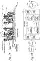
- FIG. 1is an illustration of a parking payment/bicycle rental station 100, i.e., station, according to some embodiments.
- the station 100has a meter 110, input/output control (ioctl) module 120, a number of bicycle docks 131, and a power plant 140.
- the station 100is in proximity to automobile parking spaces.
- the parking spacesmay be in any suitable location, such as on a nearby street, in a parking lot or in a garage.
- the meter 110provides a user interface for a customer to arrange for parking and/or rent a bicycle.
- the meterwill provide a mechanism for a customer to pay for parking or for usage of a bicycle.
- the inventionis not limited to use in conjunction with systems in which parking or bicycle "rental" requires payment of a fee.
- Meter 110may alternatively or additionally provide a mechanism for the system and users to exchange information, such as to identify a user "renting" a bicycle or to indicate a scheduled return time of a bike.
- Meter 110may be implemented using mechanisms known for automated meter systems for parking. However, those techniques may be modified to support transactions with individuals performing bicycle rental related operations. For example, parking meters that present a user interface, receive user input and process payments are known and may be implemented using computer processors programmed to perform parking payment functions. However, any suitable mechanism may be used to implement meter 110.
- Meter 110includes a mechanism to communicate with one or more bicycle modules 130.
- Modules 130may include a mechanism to store bicycles and secure them until rented, but release them under control of meter 110 when they are rented.
- modules 130may include a mechanism to sense status information related to bicycles, such that a bicycle has been returned, and communicate that status information to meter 110.
- bicycles 150are secured to bicycle docks 131.
- the meter 110may transmit to the ioctl module 120 information specifying the bicycle dock 131 at which the rental bicycle is stored.
- the bicycle docks 131may be divided among one or more bicycle modules 130. This provides flexibility for bicycle docks to be easily added, removed, and relocated. In the illustrative example, three bicycles modules, modules 130A-C, are shown. However, a station 100 may have any number of bicycle modules.
- Operation of both meter 110 and bicycle modules 130may require electric power to operate computers or wireless communication mechanisms, sense status related to bicycles, actuate locking mechanisms or perform other suitable functions.
- power for these operationsis derived from solar power. Solar power facilitates easy deployment of stations throughout a wide area.
- station 100includes a power plant 140.
- Power plant 140may use a solar panel and energy storage device (ESD) to provide sufficient solar power such that the station 100 may be run without a connection to a power source external to the station.
- ESDenergy storage device
- Station 100may be part of a system of stations.
- FIG. 2is a block diagram showing a system having a service area 200 and hosting center 300.
- the service area 200may have a number of stations 210A-F.
- Each station 210A-Fmay be similar to station 100 ( FIG. 1 ). However, the stations may be of a variety of service capabilities.
- station 210A and station 210Bare both parking stations while station 210C and station 210D are both bicycle stations.
- Station 210E and station 210Fare hybrid parking/bike stations.
- a stationmay provide automated-teller machine (ATM) services.
- ATMautomated-teller machine
- the stations 210A-Fmay be in communication with the hosting center 300 via connections 230.
- Hosting center 300may be a center used as is known in the art for management of interactions with parking pay station.
- the hosting centermay perform functions related to a pay-parking system, such as processing electronic payments based on user input entered at pay stations distributed over a wide area, tracking status of stations, detecting faults, scheduling maintenance or other suitable operations.
- Hosting center 300may be implemented using mechanisms as known in the art for hosting centers for pay-parking systems. These mechanisms may include one or more servers programmed to perform suitable functions. These mechanisms may also be adapted to perform functions that support a distributed bicycle rental system.
- the hosting center 300serves as the central repository of information used by the system.
- the hosting center 300may have any number of servers 310 for processing payment information and managing bicycle rentals, parking spaces and other system information.
- the hosting center 300may have a parking database 320 that stores information related to parking.
- the hosting center 300may have rental database 330 that stores information related to bicycle rental. These and other databases may be accessible to the server 310.
- the hosting center 300may also support the connection of a portable digital assistant (PDA) 220A-B.
- PDAportable digital assistant
- PDA'smay be used by parking officers for parking enforcement or by mobile technicians to monitor any problem that might occur with the stations.
- This same infrastructuremay be adapted for use in connection with bicycle rentals. For example, PDA's may be used to report damaged, defective, or missing bicycles.
- the hosting center 300may also have any number of workstations such as workstation 340A which is local to the hosting center, or workstation 340B which remotely connects to the hosting center via connection 350. Workstations may be used by operator officers to monitor, configure, and support the system. For example, a price change could be controlled from a workstation.
- FIG. 3is a block diagram of a parking payment/bicycle rental station 100 that mirrors the embodiment of station 100 illustrated in FIG. 1 .
- the structural components of the parking payment/bicycle rental meter 110are described in detail with reference to FIGS. 4A -F .
- the structural components of the bicycle module 130A-C and bicycle docks 131are described in detail with reference to FIGS. 5A -B .
- a station 100is shown having a meter 110, ioctl module 120, bike modules 130A-C and power plant 140.
- connection 230may be a wireless connection, though in other embodiments, a telephone landline or other suitable wired connection may be used. As one example, connection 230 may be implemented using a WWAN, such as a cellular network.
- connection 162may also be a wireless connection, though in other embodiments, a wired connection may be used. As one example, connection 162 may be implemented using wireless LAN or PAN technology.
- the ioctl module 120is connected to each of the bicycle docks 131 via communications and power cable 164. With these connections, status and control information can be exchanged between bicycle docks 131, meter 110 and hosting center 300.
- Each bicycle dock 131securely stores a bicycle and may include one or more sensor and actuators to obtain status information about bicycles (such as whether a bicycle is present or the condition of the bicycle) and to hold or release the bicycle in response to electronic commands.
- bicycle docks 131are shown as part of bicycle modules 130.
- Three bicycle modules 130A-Care shown, however any number of bicycle modules may be used.
- the bicycle modules 130A-Cmay be interconnected via communications and power cable 164.
- the modulesare shown daisy chained, however, any suitable connection method may be used.
- the station 100also has a power plant 140.
- the power plantcollects solar energy via solar panel 141 and stores this energy in an energy storage device (ESD) 143.
- ESDenergy storage device
- ESD 143is a battery. Power from the power plant 140 provides power via power cable 164 to operate bicycle docks 131, and ioctl module 120.
- the meter 110may have a solar panel 118 and an ESD 119. In some embodiments power stored by ESD 119 is shared with power stored by ESD 143 via power cable 166 to facilitate powering each of the station components. In some other embodiments the solar panel 118 and ESD 119 of meter 110 only provide power for meter 110. Alternatively, in some embodiments, the station 100 is directly connected to an external power source.
- FIG. 4Ais an illustration of meter 110 according to an embodiment of the invention.
- FIG. 4Bis a block diagram of the meter 110 illustrated in FIG. 4A .
- Meter 110may provide a user interface for customers to pay for parking or rent a bicycle. These interfaces may include an ID reader 112, a graphical user interface (GUI) 116, a payment interface 115, a printer 113, and any other interface for facilitating station functions. Operational behavior between devices and interfaces may be coordinated by computer 115.
- ID reader 112is a receiver adapted to receive short range wireless communications emitted by a tag on a bicycle, such as an RFID card reader that may receive communications emanating from a tag on a bicycle. (Further details of the user experience at meter 110 are discussed in a subsequent section with reference to FIGs. 6A -B , 7A-F , and 10A-B .)
- GUI 116may comprise a display for presenting visual information.
- the displaymay be a touch-screen display.
- the meter 110has a modular display socket 440 ( FIG 4A ).
- the modular display socket 440may provide an electrical coupling to the display and may mechanically secure the display in position. In this way power usage may be tailored to reflect seasonal changes. For example, during the summer season, longer daytime hours may enable more solar power to be collected and permit a large, high resolution, full color display to be used at a station. The same station in the winter may be equipped with a display that uses considerably less power or that is smaller and therefore operates in cold weather using the same amount of power.
- the modular display socket 440may connect to any of a number of compatible display types.
- the modular display socket 440may be adapted to connect to displays of various sizes.
- FIG. 4Cillustrates a small display 410 having a principle dimension 412 of length d 1 .
- FIG. 4Eillustrates small display 410 electrically coupled to and mechanically secured to the modular display socket 440 in meter 110.
- FIG. 4Dillustrates a large display 430 having a principle dimension 432 of length d 2 .
- FIG. 4Fillustrates large display 430 electrically coupled to and mechanically secured to the modular display socket 440 in meter 110.
- d 2is drawn greater than d 1 to emphasize that the modular display socket may be adapted to connect to displays of various sizes.
- the modular display socket 440may be adapted to connect to displays of various resolutions and color depths.
- modular display socket 440may be adapted to connect a grayscale display (i.e, black and white or monochromatic display) or a color display.
- screen image 1010FIG. 10A
- Screen image 1020FIG. 10B
- FIG. 10Bis an image of a low resolution black and white display.
- Connection 230is formed to enable bidirectional transmission of information related to the services provided at station 100.
- Connection 230may be formed using any appropriate communication technology.
- connection 230may be formed wirelessly using General Packet Radio Service (GPRS) utilizing Global System for Mobile Communications (GSM), IEEE 802.11, IEEE 802.16, or any other appropriate wireless protocol.
- GSMGlobal System for Mobile Communications
- IEEE 802.11, IEEE 802.16, or any other appropriate wireless protocolAlternatively, a wired connection such as Ethernet, telephone, or any other appropriate wired connection may be used.
- the connectionmay be made through the internet or another third party network.
- Transceiver 111is appropriate to the selected communication technology for forming connection 230.
- FIG. 5Ashows an embodiment of bicycle module 130.
- FIG. 5Bshows a block diagram of bicycle module 130 as connected to bicycle modules 130A and 130C and the ioctl module 120.
- the bicycle module 130comprises a number of bicycle docks 131.
- bicycle module 130has five bicycle docks.
- the bicycle modulemay have a communications and power cable 164, which may be connected to adjacent bicycle modules such as bicycle module 130A and 130C, form termination 134, be connected to ioctl module 120 ( FIG. 5B ), or connected to power plant 140 ( FIG. 3 ).
- the communications and power cable 164 in the sketch of bicycle module 130 ( FIG. 5A )is visible in the illustration, however, the cable may be embedded, or partially embedded in bicycle module 130 and bicycle docks 131.
- Each bicycle dock 131may be equipped with a locking mechanism 132 for securing bicycles.
- the locking mechanismmay be of any suitable type.
- the locking mechanism 132may be actuated to lock or unlock using power supplied from the power plant 140 ( FIG. 3 ).
- the locking mechanismmay function in a low-power consumption state. A device in a low-power consumption state may draw a reduced amount of power or no power at all from power plant 140.
- the bicycle dock 131may further comprise a bicycle ID reader 133.
- Bicycle ID reader 133may be positioned on bicycle dock 131 such as to be able to read a bicycle ID tag 151 when bicycle 150 is parked at the bicycle dock.
- RFIDis the exemplary technology.
- any appropriate technologymay be used to identify bicycle 150.
- a bar code and bar code scannermay be used.
- the bicycle ID reader 133may similarly have a low-power consumption state.
- the bicycle dock 131may further comprise a member ID reader 135.
- Member ID readermay be used to read a "membership card” (not shown). Membership is presently discussed.
- customersmay choose to become "members.” Members may eliminate some or all steps performed at the meter 110 ( FIG. 1 ) and perform formalities of the rental process at bicycle dock 131. This may be facilitated by a membership card and a membership information database stored at the hosting center 300 ( FIG. 2 ).
- Membersmay also eliminate some steps of the parking payment process.
- parking payment and bicycle rental membershipsare differentiated, while in other embodiments, the membership is combined.
- the membership cardis an RFID card
- member ID reader 135is an RFID reader.
- the functionality of ID readers 133 and 135may be consolidated into a single reader.
- member ID reader 135may be a magnetic card reader.
- member ID reader 135may similarly have a low-power consumption state.
- the bicycle dock 131may further comprise a display 136 ( FIG. 5B ).
- the displaymay be used to communicate information about a given bicycle dock such as the bicycle is damaged and not available or that the dock is broken and not available. Any suitable form of display may be used.
- the displaymay be a textual or graphical display, such as may be formed using an LCD display panel. Though, in some embodiments, other display mechanisms may be used.
- a displaymay be formed from LEDs (light-emitting diodes) controlled to communicate information to the user, such as whether a bicycle is damaged or locked to the bicycle dock.
- the displaymay also have a low-power consumption state. In some embodiments the low-power consumption state may include first reducing power consumption, and subsequently turning off a device.
- the displaymay first dim and then, after a longer period of inactivity go blank.
- Other componentsmay similarly enter low power states to implement an overall mode of operation that reduces power usage.
- wireless transmitters and receiversmay turn off after a very brief period of inactivity, but a user interface or sensors may remain powered on during a longer period of inactivity.
- a low-power statemay be determined by the availability of power or any other suitable way.
- one or more trigger mechanismsare included.
- the trigger mechanismis a mechanical switch.
- the switchis mechanical.
- Separate trigger mechanismsmay be included on meter 10 and bicycle modules 130, though in some embodiments, a single trigger mechanism may be employed.
- bicycle dock 131includes one or more trigger mechanisms 137.
- Trigger mechanism 137may be used to wake-up some of the electronic elements of the dock, bringing these elements out of the low-power consumption state. Devices may be in a low-power consumption state where low or no power is consumed to conserve solar power.
- the trigger mechanism 137may take any appropriate form such as a button or a switch.
- the trigger mechanism 137is a mechanical device. The trigger mechanism 137 is activated by user action, specifically when a bicycle is placed in a bicycle dock.
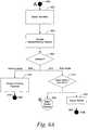
- PROCESS FLOW OF STATION 100WITH REFERENCE TO FIGS. 6A-10B
- Station 100may support various types of activities such as parking payment and bicycle rental or return. To perform these activities, the various aspects of station 100 perform operations in an order determined in part by customer inputs. The operational flow of station 100 is illustrated by the block diagrams of FIGS. 6A -C, 8, and 9 .
- parts of the operation flow performed by meter 110may have a corresponding image displayed on a display, e.g., small display 410 or large display 430, of the GUI 116 ( FIG. 4B ). These images may present information to the customer or prompt the customer to enter information. Example illustrations of the screen images are shown by FIGS. 7A -F and 10A-B .
- Process flow of station 100is described as it relates to an exemplary customer experience which begins at meter 110.
- the meter 110may be in a low-power consumption mode which may be entered after a predetermined time without customer activity. If meter 110 is in a low-power mode, at step 602 it may be "woken up" in response to a trigger. For example, a customer may touch the touch-screen display portion of GUI 116.
- meter 110may present a display of customer options (step 604).
- GUI 116may display screen 710 ( FIG. 7A ) with the prompt 711 "please make a selection." Here two options are show: option 713 is “pay for parking” and option 715 is "bicycle rental.”
- meter 110may await a customer selection.
- option 713 and option 715( FIG. 7A ) is understood to correspond with path 608, parking mode, and path 610, bike mode, respectively. In some embodiments more or less options may be available to the customer.
- FIGS. 10A -Bshow illustrative screen images 1010 and 1020, respectively.
- screen images 1010 and 1020may be presented by GUI 116 to facilitate parking payment.
- step 612the process flow ends at step 618.
- Meter 110may return to A 600, enter low-power consumption mode, or perform another suitable operation.
- step 614additional bicycle rental options may be presented.
- a customermay modify an existing rental agreement, or rent a bicycle.
- GUI 116may display screen 720 ( FIG. 7B ) with the prompt 712 "please make a selection."
- option 723is "modify rental”
- option 725is "rent bicycle.”
- Process flowcontinues to step 622 in FIG. 6A if modify rental (e.g., selecting option 723, FIG 7B ) is chosen by the customer.
- a usermay adjust the rental. For example, additional rental time may be added, a bicycle may be reported stolen or broken, or a customer may swap bicycles.
- process flowends at step 624.
- the meter 110may return A 600 or to another suitable operation.
- process flowcontinues to B 620 if a customer chooses to rent a bicycle, for example, by selecting option 725 ( FIG 7B ).
- an inquiryis made as to the availability of bicycles.
- An updatemay be made by communicating with hosting center 300 or with ioctl module 120. If bicycles are not available a message indicating such may be displayed (step 630) and the process flow is ended at step 632. The process flow may return A 600 or to another suitable operation. If bicycles are available process flow continues to step 634.
- GUI 116may display screen 730 ( FIG. 7C ) with the prompt 731 "please select an available bicycle.”
- screen 730presents options 733, 735, 737, and 739 which correspond to different bicycle sizes.
- a customer selection of a bicycleis received.
- Process flowmay continue to step 638 where the bicycle is temporarily reserved.
- a contractmay be presented to the customer.
- GUI 116may display screen 740 ( FIG. 7D ) with the statement 741 "bicycle temporarily reserved.” This may be followed by the contract language 743 and a prompt 745 such as "do you accept the contract?"
- GUI 116may display options 747 and 749 correspond to "no,” (do not accept the contract) and "accept,” (accept the contract), respectively.
- step 642payment may be made.
- Paymentmay be received in any suitable way such as by credit card or through a membership account. Payment may be facilitated, in part, by payment unit 115 of meter 110.
- GUI 116may display screen 750 ( FIG. 7E ) with the prompt 751 "please insert credit card or member card.”
- the pricemay further depend on additional options such as the rental length, type of bicycle, and return location.
- step 644instructions are presented to the user. These instructions may include instructions on how to unlock the bicycle.
- GUI 116may display screen 760 ( FIG. 7F ) with a statement 761 indicating the rental is authorized and a statement 763 with instructions on where and how to unlock the rented bicycle.
- a receiptmay be printed, for example by printer 113 of meter 110.
- Process flowcontinues at C 648 to operations which may be performed at bicycle dock 131. This process flow is described with reference to FIG. 6C .
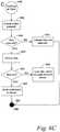
- Process flowcontinues from C 648 on FIG. 6C to step 652 where bicycle dock 131 ( FIG 5B ) is activated.
- Activationmay, for example, be in response to an activation of trigger mechanism 137.
- Trigger mechanism 137for example, may be a button or any appropriate triggering device.
- Activationprompts step 654 where it is determined if the bicycle is reserved. If the bicycle is note reserved, process flow continues to step 656 where an indication is provided. This may lead bicycle dock 131 to continue to end step 665 and the dock may enter a standby, or low-power consumption mode.
- step 658If however, the bicycle is reserved, process flow continues to step 658 and the bicycle is unlocked.
- step 660the bicycle dock determines if the bicycle has been removed. If the bike has not been removed, process flow continues to step 662 where the lock is again secured, and a "not used" event is reported. This event may be reported to meter 110 via ioctl module 120 and may further be reported to hosting center 300 for recordation. This may lead bicycle dock 131 to continue to end step 665.
- a "used" eventis reported. Reporting may be performed in the same way as for a "not used” event.
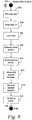
- FIG. 8is a process flow diagram showing a rental process for a member when performed at bicycle dock 131.
- a pass key or member cardis read. If the reading is invalid (step 804), an indication of such is made at step 806 and the process flow is ended (step 830).
- step 804If the reading is valid (step 804) it is determined if the bike is available for use (step 808). If the bicycle is not available, an indication of such is made at step 810 and process flow is ended (step 830).
- a request for rentalis made (step 812). For example, a request may be sent to the hosting center 300 via ioctl module 120 and meter 110.
- a response from the serveris anticipated. If no response is received an indication of such is made (step 816) and process flow is ended (step 830).
- step 814If a response from the server is received (step 814), process flow continues to step 818 where it is determined if the request was authorized. If the request was not authorized, an indication of refusal is made (step 820) and process flow is ended (step 830).
- step 818If the request is authorized (step 818), the bicycle is unlocked (step 822).
- step 824the bicycle dock determines if the bicycle has been removed. If the bike has not been removed, process flow continues to step 826 where the lock is secured, and a "not used" event is reported. This event may be reported to meter 110 via ioctl module 120, and may further be reported to hosting center 300 for recordation. This may lead bicycle dock 131 to continue to end step 830.
- the bicycle dock 131may enter a standby, or low-power consumption mode.
- FIG. 9is a process flow diagram performed when a bicycle is returned to a bicycle dock 131. The process begins at E 900.
- step 902it is detected that a bicycle 150 has been inserted into the bicycle dock 131.
- step 904the bicycle is identified. In some embodiments identification is performed using RFID.
- Step 906the bicycle is secured using the locking mechanism 132.
- An indicationmay then be made that the rental is ended (step 908).
- a reportis made that the rental has ended (step 910).
- the reportmay be transmitted to the hosting center 300 via ioctl module 120 and meter 110.
- damage to the bicyclemay be reported.
- damagemay be reported by the customer.
- the reportmay be transmitted to the hosting center 300 via ioctl module 120 and meter 110.
- a customerindicates the desire for a receipt.
- the receipt requestis transmitted to meter 110 and printed by printer 113. Process flow is terminated at step 918.
- the above-described embodiments of the present inventioncan be implemented in any of numerous ways.
- the embodimentsmay be implemented using hardware, software or a combination thereof.
- the software codecan be executed on any suitable processor or collection of processors, whether provided in a single computer or distributed among multiple computers.
- a computermay be embodied in any of a number of forms, such as a rack-mounted computer, a desktop computer, a laptop computer, or a tablet computer. Additionally, a computer may be embedded in a device not generally regarded as a computer but with suitable processing capabilities, including a Personal Digital Assistant (PDA), a smart phone or any other suitable portable or fixed electronic device.
- PDAPersonal Digital Assistant
- a computermay have one or more input and output devices. These devices can be used, among other things, to present a user interface. Examples of output devices that can be used to provide a user interface include printers or display screens for visual presentation of output and speakers or other sound generating devices for audible presentation of output. Examples of input devices that can be used for a user interface include keyboards, and pointing devices, such as mice, touch pads, and digitizing tablets. As another example, a computer may receive input information through speech recognition or in other audible format.
- Such computersmay be interconnected by one or more networks in any suitable form, including as a local area network or a wide area network, such as an enterprise network or the Internet.
- networksmay be based on any suitable technology and may operate according to any suitable protocol and may include wireless networks, wired networks or fiber optic networks.
- the various methods or processes outlined hereinmay be coded as software that is executable on one or more processors that employ any one of a variety of operating systems or platforms. Additionally, such software may be written using any of a number of suitable programming languages and/or programming or scripting tools, and also may be compiled as executable machine language code or intermediate code that is executed on a framework or virtual machine.
- a computer readable medium(or multiple computer readable media) (e.g., a computer memory, one or more floppy discs, compact discs, optical discs, magnetic tapes, flash memories, circuit configurations in Field Programmable Gate Arrays or other semiconductor devices, or other tangible computer storage medium) encoded with one or more programs that, when executed on one or more computers or other processors, perform methods that implement the various processes discussed above.
- the computer readable medium or mediacan be transportable, such that the program or programs stored thereon can be loaded onto one or more different computers or other processors to implement various processes as discussed above.
- programor “software” are used herein in a generic sense to refer to any type of computer code or set of computer-executable instructions that can be employed to program a computer or other processor to implement various processes as discussed above. Additionally, it should be appreciated that one or more computer programs that when executed perform methods described herein need not reside on a single computer or processor, but may be distributed in a modular fashion amongst a number of different computers or processors to implement various processes described herein.
- Computer-executable instructionsmay be in many forms, such as program modules, executed by one or more computers or other devices.
- program modulesinclude routines, programs, objects, components, data structures, etc. that perform particular tasks or implement particular abstract data types.
- functionality of the program modulesmay be combined or distributed as desired.
- data structuresmay be stored in computer-readable media in any suitable form.
- data structuresmay be shown to have fields that are related through location in the data structure. Such relationships may likewise be achieved by assigning storage for the fields with locations in a computer-readable medium that conveys relationship between the fields.
- any suitable mechanismmay be used to establish a relationship between information in fields of a data structure, including through the use of pointers, tags or other mechanisms that establish relationship between data elements.
- the inventionmay be embodied as a method, of which an example has been provided.
- the acts performed as part of the methodmay be ordered in any suitable way. Accordingly, embodiments may be constructed in which acts are performed in an order different than illustrated, which may include performing some acts simultaneously, even though shown as sequential acts in illustrative embodiments.
Landscapes
- Business, Economics & Management (AREA)
- Physics & Mathematics (AREA)
- General Physics & Mathematics (AREA)
- Accounting & Taxation (AREA)
- Finance (AREA)
- Engineering & Computer Science (AREA)
- Theoretical Computer Science (AREA)
- Strategic Management (AREA)
- General Business, Economics & Management (AREA)
- Economics (AREA)
- Development Economics (AREA)
- Marketing (AREA)
- Mechanical Engineering (AREA)
- Tourism & Hospitality (AREA)
- Health & Medical Sciences (AREA)
- General Health & Medical Sciences (AREA)
- Human Resources & Organizations (AREA)
- Primary Health Care (AREA)
- Coin-Freed Apparatuses For Hiring Articles (AREA)
- Management, Administration, Business Operations System, And Electronic Commerce (AREA)
- Operations Research (AREA)
- Refuse Collection And Transfer (AREA)
Description
- Some cities are equipped with automatic systems for renting bicycles (bikes). These systems typically have a number of bicycle rental/storage stations located in different parts of the city. Each station enables a customer to rent, pickup, and return a bicycle.
- To prevent theft, the bicycles stored at a station are secured to a bollard, post, dock, or other relatively fixed object, by a locking mechanism. The locking mechanism may release the bicycle once a rental has been validated. The bike then becomes available to the customer for use.
- When the customer wishes to return the bicycle, the bicycle is returned to the bollard and again secured with the locking mechanism. In some bicycle rental systems, the bicycle may be returned to a bollard at any station.
- People who do not chose to use bicycles for transportation may travel by car. Motorists find it is frequently necessary to periodically stop a vehicle and leave it unoccupied for a time. For this purpose, parking spaces may be designated for the temporary storage of vehicles. To prevent abuse and/or as a source of revenue, these parking spaces may be metered, requiring motorists to pay to park.
- To collect payment, a parking meter may be located in close proximity to the parking space. This parking meter may be used to meter a single space, or a group of spaces. These spaces may be in close proximity to the meter on the side of a street, or part of a parking lot. For example, the assignee of the present application provides an automated parking payment and management system.
- Further background is provided in the following documents.
FR 2 764 261 A1 JP 2003 331 395 A JP 2005 180 161 A FR 2824 942 A - Reference is also made to
DE 10 2007 012 099 A1 . - An integrated automobile parking payment and management system and bicycle rental system are presented. In this way, the same infrastructure can support motorists paying for parking and bicyclists renting bikes. To enable deployment of such a system throughout a wide area, stations, which may provide for parking payment, bicycle rental or both, are solar powered, and have power saving features.
- The present invention provides a bicycle rental station according to Claim 1, and a method of operating a bicycle rental station according to Claim 10. Optional features are set out in the dependent claims.
- In some embodiments, customers may pay for parking or pickup or return bicycles at an automated station. The automated station may have a parking/bike meter, bicycle docks, input/output control (ioctl) module, and power plant. The bicycle docks may be divided among a number of bicycle modules. The bicycle modules may be secured in place at the station, but may also provide flexibility such that they may be added to or remove from a station to meet customer demand. The ioctl module may be used for communication between the meter and the bicycles modules. The power plant acts as a power source for the station and has a solar panel and energy storage device. Low-power operation may be achieved by placing some electronics in a low-power mode. Each bicycle dock may have a trigger mechanism that when activated powers on associated electronics.
- The invention and embodiments thereof will be better understood when the following detailed description is read in conjunction with the accompanying drawing figures. In the figures, elements are not necessarily drawn to scale. In general, like elements appearing in multiple figures are identified by a like reference designation. In the drawings:
FIG. 1 is a sketch of a parking payment and bicycle rental station;FIG. 2 is a block diagram of a system according to an embodiment of the invention;FIG. 3 is a block diagram of a parking payment and bicycle rental station;FIG. 4A is an illustration of a parking payment and bicycle rental meter;FIG. 4B is a block diagram of a parking payment and bicycle rental meter;FIG. 4C is an illustration of a small display;FIG. 4D is an illustration of a large display;FIG. 4E is an illustration of a small display connected to a parking payment/bicycle rental meter;FIG. 4F is an illustration of a large display connected to a parking payment/bicycle rental meter;FIG. 5A is a sketch of a bicycle module according to an embodiment of the invention;FIG. 5B is a block diagram of a portion of the parking payment/bicycle rental station;FIG. 6A is a process flow diagram of a portion of a process of operating a parking payment and bicycle rental meter according to an embodiment of the invention;FIG. 6B is a process flow diagram of a portion of a bicycle rental process that may be performed using a meter according to an embodiment of the invention;FIG. 6C is a process flow diagram of a portion of a bicycle rental process that may be performed using a bicycle module according to an embodiment of the invention;FIG. 7A is a conceptual sketch of a screen for selecting either the parking payment or bicycle rental mode according to an embodiment of the invention;FIG. 7B is a conceptual sketch of a screen for selecting to either modify an existing rental or start a new rental according to an embodiment of the invention;FIG. 7C is a conceptual sketch of a screen for selecting a bicycle according to an embodiment of the invention;FIG. 7D is a conceptual sketch of a screen for accepting a bicycle rental contract according to an embodiment of the invention;FIG. 7E is a conceptual sketch of a screen for prompting a payment according to an embodiment of the invention;FIG. 7F is a conceptual sketch of a screen presenting instructions for picking up a bicycle according to an embodiment of the invention.FIG. 8 is a process flow diagram of a bicycle rental process that may be performed by a parking payment/bicycle rental station according to an embodiment of the invention;FIG. 9 is a process flow diagram of a bicycle rental return process that may be performed using a parking payment and bicycle rental station according to an embodiment of the invention;FIG. 10A is a gray scale illustration of a high resolution color screen presenting a user interface for parking payment; andFIG. 10A is a black and white illustration of a low resolution screen presenting a user interface for parking transactions using a payment and management system according to some embodiments of the invention.- The inventors have recognized and appreciated that, although generally used for different reasons by different people, automated parking payment and management and bicycle rental services may be combined to yield synergies. An embodiment of the invention provides a single automated meter at which parking may be paid for and a bicycle may be rented. In some embodiments, the meter may be part of a station, which in turn may be part of a larger network of stations. Further, in some embodiments the network of stations may be managed by a hosting center, which can process common aspects of bicycle rental and parking payment transactions, such as managing payments or maintaining databases.
- A station may have sufficiently low power requirements such that it is operable from power collected from a solar panel and stored in an energy storage device. During inactive periods, the station enters a low-power consumption mode. Activation of a trigger mechanism causes a portion of the station to power on. Other power management features may be included to also enable operation within available power levels. For example, the meter may feature a modular display socket for connecting different display types to accommodate seasonal variations. For example, a lower power display may be used in the winter when less sunlight is available. Similarly, a smaller display or display with more limited functionality may be used to accommodate cold weather operation.
FIG. 1 is an illustration of a parking payment/bicycle rental station 100, i.e., station, according to some embodiments. Thestation 100 has ameter 110, input/output control (ioctl)module 120, a number ofbicycle docks 131, and apower plant 140. According to some embodiments thestation 100 is in proximity to automobile parking spaces. Though not shown inFIG. 1 , the parking spaces may be in any suitable location, such as on a nearby street, in a parking lot or in a garage.- The
meter 110 provides a user interface for a customer to arrange for parking and/or rent a bicycle. In some embodiments, the meter will provide a mechanism for a customer to pay for parking or for usage of a bicycle. However, the invention is not limited to use in conjunction with systems in which parking or bicycle "rental" requires payment of a fee.Meter 110 may alternatively or additionally provide a mechanism for the system and users to exchange information, such as to identify a user "renting" a bicycle or to indicate a scheduled return time of a bike. Meter 110 may be implemented using mechanisms known for automated meter systems for parking. However, those techniques may be modified to support transactions with individuals performing bicycle rental related operations. For example, parking meters that present a user interface, receive user input and process payments are known and may be implemented using computer processors programmed to perform parking payment functions. However, any suitable mechanism may be used to implementmeter 110.Meter 110 includes a mechanism to communicate with one ormore bicycle modules 130.Modules 130 may include a mechanism to store bicycles and secure them until rented, but release them under control ofmeter 110 when they are rented. In addition,modules 130 may include a mechanism to sense status information related to bicycles, such that a bicycle has been returned, and communicate that status information tometer 110.- In the embodiment illustrated, bicycles 150 are secured to
bicycle docks 131. In some embodiments, when a bicycle is rented by a user themeter 110 may transmit to theioctl module 120 information specifying thebicycle dock 131 at which the rental bicycle is stored. Thebicycle docks 131 may be divided among one ormore bicycle modules 130. This provides flexibility for bicycle docks to be easily added, removed, and relocated. In the illustrative example, three bicycles modules,modules 130A-C, are shown. However, astation 100 may have any number of bicycle modules. - Operation of both
meter 110 andbicycle modules 130 may require electric power to operate computers or wireless communication mechanisms, sense status related to bicycles, actuate locking mechanisms or perform other suitable functions. In the embodiment illustrated, power for these operations is derived from solar power. Solar power facilitates easy deployment of stations throughout a wide area. - Accordingly,
station 100 includes apower plant 140.Power plant 140 may use a solar panel and energy storage device (ESD) to provide sufficient solar power such that thestation 100 may be run without a connection to a power source external to the station. Station 100 may be part of a system of stations.FIG. 2 is a block diagram showing a system having aservice area 200 and hostingcenter 300. Theservice area 200 may have a number ofstations 210A-F. Eachstation 210A-F may be similar to station 100 (FIG. 1 ). However, the stations may be of a variety of service capabilities. In the figure,station 210A andstation 210B are both parking stations whilestation 210C andstation 210D are both bicycle stations.Station 210E andstation 210F are hybrid parking/bike stations.- These service capabilities are exemplary and alternate and/or additional services may be provided by some station. For example, a station may provide automated-teller machine (ATM) services.
- The
stations 210A-F may be in communication with the hostingcenter 300 viaconnections 230.Hosting center 300 may be a center used as is known in the art for management of interactions with parking pay station. The hosting center may perform functions related to a pay-parking system, such as processing electronic payments based on user input entered at pay stations distributed over a wide area, tracking status of stations, detecting faults, scheduling maintenance or other suitable operations. Hosting center 300 may be implemented using mechanisms as known in the art for hosting centers for pay-parking systems. These mechanisms may include one or more servers programmed to perform suitable functions. These mechanisms may also be adapted to perform functions that support a distributed bicycle rental system.- In the embodiment illustrated, the hosting
center 300 serves as the central repository of information used by the system. The hostingcenter 300 may have any number ofservers 310 for processing payment information and managing bicycle rentals, parking spaces and other system information. The hostingcenter 300 may have aparking database 320 that stores information related to parking. The hostingcenter 300 may haverental database 330 that stores information related to bicycle rental. These and other databases may be accessible to theserver 310. - The hosting
center 300 may also support the connection of a portable digital assistant (PDA) 220A-B. PDA's may be used by parking officers for parking enforcement or by mobile technicians to monitor any problem that might occur with the stations. This same infrastructure may be adapted for use in connection with bicycle rentals. For example, PDA's may be used to report damaged, defective, or missing bicycles. - The hosting
center 300 may also have any number of workstations such asworkstation 340A which is local to the hosting center, orworkstation 340B which remotely connects to the hosting center viaconnection 350. Workstations may be used by operator officers to monitor, configure, and support the system. For example, a price change could be controlled from a workstation. FIG. 3 is a block diagram of a parking payment/bicycle rental station 100 that mirrors the embodiment ofstation 100 illustrated inFIG. 1 . The structural components of the parking payment/bicycle rental meter 110 are described in detail with reference toFIGS. 4A -F . The structural components of thebicycle module 130A-C andbicycle docks 131 are described in detail with reference toFIGS. 5A -B .- A
station 100 is shown having ameter 110,ioctl module 120,bike modules 130A-C andpower plant 140. - The
meter 110 is in communication with hosting station 300 (FIG. 2 ) viaconnection 230.Connection 230 may be a wireless connection, though in other embodiments, a telephone landline or other suitable wired connection may be used. As one example,connection 230 may be implemented using a WWAN, such as a cellular network. - The
meter 110 is in communication withioctl module 120 viaconnection 162.Connection 162 may also be a wireless connection, though in other embodiments, a wired connection may be used. As one example,connection 162 may be implemented using wireless LAN or PAN technology. - The
ioctl module 120 is connected to each of thebicycle docks 131 via communications andpower cable 164. With these connections, status and control information can be exchanged betweenbicycle docks 131,meter 110 and hostingcenter 300. - Each
bicycle dock 131 securely stores a bicycle and may include one or more sensor and actuators to obtain status information about bicycles (such as whether a bicycle is present or the condition of the bicycle) and to hold or release the bicycle in response to electronic commands. - Here the
bicycle docks 131 are shown as part ofbicycle modules 130. Threebicycle modules 130A-C are shown, however any number of bicycle modules may be used. Thebicycle modules 130A-C may be interconnected via communications andpower cable 164. Here the modules are shown daisy chained, however, any suitable connection method may be used. - The
station 100 also has apower plant 140. The power plant collects solar energy viasolar panel 141 and stores this energy in an energy storage device (ESD) 143. - In some
embodiments ESD 143 is a battery. Power from thepower plant 140 provides power viapower cable 164 to operatebicycle docks 131, andioctl module 120. Themeter 110 may have asolar panel 118 and anESD 119. In some embodiments power stored byESD 119 is shared with power stored byESD 143 viapower cable 166 to facilitate powering each of the station components. In some other embodiments thesolar panel 118 andESD 119 ofmeter 110 only provide power formeter 110. Alternatively, in some embodiments, thestation 100 is directly connected to an external power source. FIG. 4A is an illustration ofmeter 110 according to an embodiment of the invention.FIG. 4B is a block diagram of themeter 110 illustrated inFIG. 4A .Meter 110 may provide a user interface for customers to pay for parking or rent a bicycle. These interfaces may include anID reader 112, a graphical user interface (GUI) 116, apayment interface 115, aprinter 113, and any other interface for facilitating station functions. Operational behavior between devices and interfaces may be coordinated bycomputer 115. In someembodiments ID reader 112 is a receiver adapted to receive short range wireless communications emitted by a tag on a bicycle, such as an RFID card reader that may receive communications emanating from a tag on a bicycle. (Further details of the user experience atmeter 110 are discussed in a subsequent section with reference toFIGs. 6A -B ,7A-F , and10A-B .)GUI 116 may comprise a display for presenting visual information. The display may be a touch-screen display. In some embodiments themeter 110 has a modular display socket 440 (FIG 4A ). Themodular display socket 440 may provide an electrical coupling to the display and may mechanically secure the display in position. In this way power usage may be tailored to reflect seasonal changes. For example, during the summer season, longer daytime hours may enable more solar power to be collected and permit a large, high resolution, full color display to be used at a station. The same station in the winter may be equipped with a display that uses considerably less power or that is smaller and therefore operates in cold weather using the same amount of power.- The
modular display socket 440 may connect to any of a number of compatible display types. For example, themodular display socket 440 may be adapted to connect to displays of various sizes.FIG. 4C illustrates asmall display 410 having aprinciple dimension 412 of lengthd1.FIG. 4E illustratessmall display 410 electrically coupled to and mechanically secured to themodular display socket 440 inmeter 110. FIG. 4D illustrates alarge display 430 having aprinciple dimension 432 of lengthd2.FIG. 4F illustrateslarge display 430 electrically coupled to and mechanically secured to themodular display socket 440 inmeter 110.- Here,d2 is drawn greater thand1 to emphasize that the modular display socket may be adapted to connect to displays of various sizes.
- The
modular display socket 440 may be adapted to connect to displays of various resolutions and color depths. For example,modular display socket 440 may be adapted to connect a grayscale display (i.e, black and white or monochromatic display) or a color display. For example screen image 1010 (FIG. 10A ) is a gray scale representation of an image displayed on a high resolution color screen. Screen image 1020 (FIG. 10B ) is an image of a low resolution black and white display. Meter 110 has atransceiver 111 for communication information with hostingstation 300 via connection 230 (FIG. 2 ).Connection 230 is formed to enable bidirectional transmission of information related to the services provided atstation 100.Connection 230 may be formed using any appropriate communication technology. For example,connection 230 may be formed wirelessly using General Packet Radio Service (GPRS) utilizing Global System for Mobile Communications (GSM), IEEE 802.11, IEEE 802.16, or any other appropriate wireless protocol. Alternatively, a wired connection such as Ethernet, telephone, or any other appropriate wired connection may be used. In some embodiments the connection may be made through the internet or another third party network.Transceiver 111 is appropriate to the selected communication technology for formingconnection 230.- Turning now
FIGs. 5A -B, FIG. 5A shows an embodiment ofbicycle module 130.FIG. 5B shows a block diagram ofbicycle module 130 as connected tobicycle modules ioctl module 120. - The
bicycle module 130 comprises a number ofbicycle docks 131. In the example embodiment illustrated inFIG. 5A ,bicycle module 130 has five bicycle docks. The bicycle module may have a communications andpower cable 164, which may be connected to adjacent bicycle modules such asbicycle module form termination 134, be connected to ioctl module 120 (FIG. 5B ), or connected to power plant 140 (FIG. 3 ). The communications andpower cable 164 in the sketch of bicycle module 130 (FIG. 5A ), is visible in the illustration, however, the cable may be embedded, or partially embedded inbicycle module 130 andbicycle docks 131. - Each
bicycle dock 131 may be equipped with alocking mechanism 132 for securing bicycles. The locking mechanism may be of any suitable type. Thelocking mechanism 132 may be actuated to lock or unlock using power supplied from the power plant 140 (FIG. 3 ). The locking mechanism may function in a low-power consumption state. A device in a low-power consumption state may draw a reduced amount of power or no power at all frompower plant 140. - The
bicycle dock 131 may further comprise abicycle ID reader 133.Bicycle ID reader 133 may be positioned onbicycle dock 131 such as to be able to read abicycle ID tag 151 whenbicycle 150 is parked at the bicycle dock. Here, RFID is the exemplary technology. However, any appropriate technology may be used to identifybicycle 150. For example a bar code and bar code scanner may be used. Like thelocking mechanism 132, thebicycle ID reader 133 may similarly have a low-power consumption state. - The
bicycle dock 131 may further comprise amember ID reader 135. Member ID reader may be used to read a "membership card" (not shown). Membership is presently discussed. - In some embodiments of the system customers may choose to become "members." Members may eliminate some or all steps performed at the meter 110 (
FIG. 1 ) and perform formalities of the rental process atbicycle dock 131. This may be facilitated by a membership card and a membership information database stored at the hosting center 300 (FIG. 2 ). - Members may also eliminate some steps of the parking payment process. In some embodiments parking payment and bicycle rental memberships are differentiated, while in other embodiments, the membership is combined.
- In some embodiments the membership card is an RFID card, and
member ID reader 135 is an RFID reader. In some embodiments, for example, when RFID is use, the functionality ofID readers - Any appropriate technology may be used to identify members. For example, members may use cards with a magnetic strip to gain access to
bicycle 150. In this case,member ID reader 135 may be a magnetic card reader. - Like the
locking mechanism 132 and thebicycle ID reader 133,member ID reader 135 may similarly have a low-power consumption state. - The
bicycle dock 131 may further comprise a display 136 (FIG. 5B ). The display may be used to communicate information about a given bicycle dock such as the bicycle is damaged and not available or that the dock is broken and not available. Any suitable form of display may be used. In some embodiments, the display may be a textual or graphical display, such as may be formed using an LCD display panel. Though, in some embodiments, other display mechanisms may be used. For example, a display may be formed from LEDs (light-emitting diodes) controlled to communicate information to the user, such as whether a bicycle is damaged or locked to the bicycle dock. The display may also have a low-power consumption state. In some embodiments the low-power consumption state may include first reducing power consumption, and subsequently turning off a device. For example, the display may first dim and then, after a longer period of inactivity go blank. Other components may similarly enter low power states to implement an overall mode of operation that reduces power usage. For example, wireless transmitters and receivers may turn off after a very brief period of inactivity, but a user interface or sensors may remain powered on during a longer period of inactivity. When a device enters a low-power state may be determined by the availability of power or any other suitable way. - To cause the station to return from a low power state, one or more trigger mechanisms are included. In embodiments in which the system may enter a low power state in which all electronics are powered off, the trigger mechanism is a mechanical switch. In embodiments in which some electronics components operate in low power mode, the switch is mechanical. Separate trigger mechanisms may be included on meter 10 and
bicycle modules 130, though in some embodiments, a single trigger mechanism may be employed. - In the example illustrated,
bicycle dock 131 includes one ormore trigger mechanisms 137.Trigger mechanism 137 may be used to wake-up some of the electronic elements of the dock, bringing these elements out of the low-power consumption state. Devices may be in a low-power consumption state where low or no power is consumed to conserve solar power. Thetrigger mechanism 137 may take any appropriate form such as a button or a switch. Thetrigger mechanism 137 is a mechanical device. Thetrigger mechanism 137 is activated by user action, specifically when a bicycle is placed in a bicycle dock. Station 100 may support various types of activities such as parking payment and bicycle rental or return. To perform these activities, the various aspects ofstation 100 perform operations in an order determined in part by customer inputs. The operational flow ofstation 100 is illustrated by the block diagrams ofFIGS. 6A -C, 8, and 9 .- In some instances, parts of the operation flow performed by
meter 110 may have a corresponding image displayed on a display, e.g.,small display 410 orlarge display 430, of the GUI 116 (FIG. 4B ). These images may present information to the customer or prompt the customer to enter information. Example illustrations of the screen images are shown byFIGS. 7A -F and10A-B . - Process flow of
station 100 is described as it relates to an exemplary customer experience which begins atmeter 110. Beginning at point A 600 inFIG. 6A , themeter 110 may be in a low-power consumption mode which may be entered after a predetermined time without customer activity. Ifmeter 110 is in a low-power mode, atstep 602 it may be "woken up" in response to a trigger. For example, a customer may touch the touch-screen display portion ofGUI 116. - After waking up, or if low-power consumption mode is not used,
meter 110 may present a display of customer options (step 604). Corresponding to step 604,GUI 116 may display screen 710 (FIG. 7A ) with the prompt 711 "please make a selection..." Here two options are show:option 713 is "pay for parking" andoption 715 is "bicycle rental." - At step 606 (
FIG. 6A ),meter 110 may await a customer selection. Hereoption 713 and option 715 (FIG. 7A ) is understood to correspond withpath 608, parking mode, andpath 610, bike mode, respectively. In some embodiments more or less options may be available to the customer. - If parking mode is selected,
path 608 is followed to step 612. Atstep 612 any suitable method for accepting parking payment may be performed.FIGS. 10A -B showillustrative screen images screen images GUI 116 to facilitate parking payment. - Once
step 612 is completed the process flow ends atstep 618.Meter 110 may return to A 600, enter low-power consumption mode, or perform another suitable operation. - If bike mode is selected,
path 610 is followed to step 614. Atstep 614 additional bicycle rental options may be presented. In the present example, a customer may modify an existing rental agreement, or rent a bicycle. Corresponding to step 614,GUI 116 may display screen 720 (FIG. 7B ) with the prompt 712 "please make a selection..." Here two options are show:option 723 is "modify rental" andoption 725 is "rent bicycle." - Process flow continues to step 622 in
FIG. 6A if modify rental (e.g., selectingoption 723,FIG 7B ) is chosen by the customer. At step 622 a user may adjust the rental. For example, additional rental time may be added, a bicycle may be reported stolen or broken, or a customer may swap bicycles. Upon completion ofstep 622 process flow ends atstep 624. Themeter 110 may return A 600 or to another suitable operation. - Alternatively, process flow continues to
B 620 if a customer chooses to rent a bicycle, for example, by selecting option 725 (FIG 7B ). - The process flow for the bicycle rental process continues from
B 620 inFIG. 6B . - At
step 628 an inquiry is made as to the availability of bicycles. An update may be made by communicating with hostingcenter 300 or withioctl module 120. If bicycles are not available a message indicating such may be displayed (step 630) and the process flow is ended atstep 632. The process flow may return A 600 or to another suitable operation. If bicycles are available process flow continues to step 634. - At
step 634 an option to select a bicycle is provided to the customer. In some embodiments a customer may select multiple bicycles for rental. Corresponding to step 634,GUI 116 may display screen 730 (FIG. 7C ) with the prompt 731 "please select an available bicycle." In this example,screen 730presents options - At step 636 a customer selection of a bicycle is received.
- Process flow may continue to step 638 where the bicycle is temporarily reserved. At step 640 a contract may be presented to the customer. Corresponding to step 640,
GUI 116 may display screen 740 (FIG. 7D ) with thestatement 741 "bicycle temporarily reserved." This may be followed by thecontract language 743 and a prompt 745 such as "do you accept the contract?"GUI 116 may displayoptions - Once a user has accepted the contract, process flow continues to step 642 where payment may be made. Payment may be received in any suitable way such as by credit card or through a membership account. Payment may be facilitated, in part, by
payment unit 115 ofmeter 110. Corresponding to step 642,GUI 116 may display screen 750 (FIG. 7E ) with the prompt 751 "please insert credit card or member card." In some embodiments, the price may further depend on additional options such as the rental length, type of bicycle, and return location. - Upon receipt of payment, process flow continues to step 644 where instructions are presented to the user. These instructions may include instructions on how to unlock the bicycle. Corresponding to step 644,
GUI 116 may display screen 760 (FIG. 7F ) with astatement 761 indicating the rental is authorized and astatement 763 with instructions on where and how to unlock the rented bicycle. - At step 646 a receipt may be printed, for example by
printer 113 ofmeter 110. Process flow continues atC 648 to operations which may be performed atbicycle dock 131. This process flow is described with reference toFIG. 6C . - Process flow continues from
C 648 onFIG. 6C to step 652 where bicycle dock 131 (FIG 5B ) is activated. Activation may, for example, be in response to an activation oftrigger mechanism 137.Trigger mechanism 137, for example, may be a button or any appropriate triggering device. - Activation prompts step 654 where it is determined if the bicycle is reserved. If the bicycle is note reserved, process flow continues to step 656 where an indication is provided. This may lead
bicycle dock 131 to continue to endstep 665 and the dock may enter a standby, or low-power consumption mode. - If however, the bicycle is reserved, process flow continues to step 658 and the bicycle is unlocked.
- After a
predetermined time step 660 is performed. Atstep 660 the bicycle dock determines if the bicycle has been removed. If the bike has not been removed, process flow continues to step 662 where the lock is again secured, and a "not used" event is reported. This event may be reported tometer 110 viaioctl module 120 and may further be reported to hostingcenter 300 for recordation. This may leadbicycle dock 131 to continue to endstep 665. - If the bicycle is detected to have been removed at step 660 a "used" event is reported. Reporting may be performed in the same way as for a "not used" event. Once the bicycle is removed process flow continues to end
step 665 and the dock may enter a standby, or low-power consumption mode. FIG. 8 is a process flow diagram showing a rental process for a member when performed atbicycle dock 131. At step 802 a pass key or member card is read. If the reading is invalid (step 804), an indication of such is made atstep 806 and the process flow is ended (step 830).- If the reading is valid (step 804) it is determined if the bike is available for use (step 808). If the bicycle is not available, an indication of such is made at
step 810 and process flow is ended (step 830). - If the bicycle is available, a request for rental is made (step 812). For example, a request may be sent to the hosting
center 300 viaioctl module 120 andmeter 110. At step 814 a response from the server is anticipated. If no response is received an indication of such is made (step 816) and process flow is ended (step 830). - If a response from the server is received (step 814), process flow continues to step 818 where it is determined if the request was authorized. If the request was not authorized, an indication of refusal is made (step 820) and process flow is ended (step 830).
- If the request is authorized (step 818), the bicycle is unlocked (step 822).
- After a
predetermined time step 824 is performed. Atstep 824 the bicycle dock determines if the bicycle has been removed. If the bike has not been removed, process flow continues to step 826 where the lock is secured, and a "not used" event is reported. This event may be reported tometer 110 viaioctl module 120, and may further be reported to hostingcenter 300 for recordation. This may leadbicycle dock 131 to continue to endstep 830. - If the bicycle is detected to have been removed at step 824 a "used" event is reported. Reporting may be performed in the same way as for a "not used" event. Once the bicycle is removed process flow continues to end
step 830. - At
end step 830 thebicycle dock 131 may enter a standby, or low-power consumption mode. FIG. 9 is a process flow diagram performed when a bicycle is returned to abicycle dock 131. The process begins atE 900.- At
step 902 it is detected that abicycle 150 has been inserted into thebicycle dock 131. Atstep 904 the bicycle is identified. In some embodiments identification is performed using RFID. - Process flow continues to step 906 where the bicycle is secured using the
locking mechanism 132. - An indication may then be made that the rental is ended (step 908). A report is made that the rental has ended (step 910). The report may be transmitted to the hosting
center 300 viaioctl module 120 andmeter 110. - At
step 912 damage to the bicycle may be reported. In some embodiments damage may be reported by the customer. The report may be transmitted to the hostingcenter 300 viaioctl module 120 andmeter 110. - At step 914 a customer indicates the desire for a receipt. At
step 916 the receipt request is transmitted tometer 110 and printed byprinter 113. Process flow is terminated atstep 918. - Having thus described several aspects of at least one embodiment of this invention, it is to be appreciated that various alterations, modifications, and improvements will readily occur to those skilled in the art.
- For example, various aspects and advantages are described. Not every embodiment may include every aspect or provide every described advantage.
- Such alterations, modifications, and improvements are intended to be part of this disclosure, and are intended to be within the scope of the invention, which is defined by the appended claims. Accordingly, the foregoing description and drawings are by way of example only.
- The above-described embodiments of the present invention can be implemented in any of numerous ways. For example, the embodiments may be implemented using hardware, software or a combination thereof. When implemented in software, the software code can be executed on any suitable processor or collection of processors, whether provided in a single computer or distributed among multiple computers.
- Further, it should be appreciated that a computer may be embodied in any of a number of forms, such as a rack-mounted computer, a desktop computer, a laptop computer, or a tablet computer. Additionally, a computer may be embedded in a device not generally regarded as a computer but with suitable processing capabilities, including a Personal Digital Assistant (PDA), a smart phone or any other suitable portable or fixed electronic device.
- Also, a computer may have one or more input and output devices. These devices can be used, among other things, to present a user interface. Examples of output devices that can be used to provide a user interface include printers or display screens for visual presentation of output and speakers or other sound generating devices for audible presentation of output. Examples of input devices that can be used for a user interface include keyboards, and pointing devices, such as mice, touch pads, and digitizing tablets. As another example, a computer may receive input information through speech recognition or in other audible format.
- Such computers may be interconnected by one or more networks in any suitable form, including as a local area network or a wide area network, such as an enterprise network or the Internet. Such networks may be based on any suitable technology and may operate according to any suitable protocol and may include wireless networks, wired networks or fiber optic networks.
- Also, the various methods or processes outlined herein may be coded as software that is executable on one or more processors that employ any one of a variety of operating systems or platforms. Additionally, such software may be written using any of a number of suitable programming languages and/or programming or scripting tools, and also may be compiled as executable machine language code or intermediate code that is executed on a framework or virtual machine.
- In this respect, there may be provided a computer readable medium (or multiple computer readable media) (e.g., a computer memory, one or more floppy discs, compact discs, optical discs, magnetic tapes, flash memories, circuit configurations in Field Programmable Gate Arrays or other semiconductor devices, or other tangible computer storage medium) encoded with one or more programs that, when executed on one or more computers or other processors, perform methods that implement the various processes discussed above. The computer readable medium or media can be transportable, such that the program or programs stored thereon can be loaded onto one or more different computers or other processors to implement various processes as discussed above.
- The terms "program" or "software" are used herein in a generic sense to refer to any type of computer code or set of computer-executable instructions that can be employed to program a computer or other processor to implement various processes as discussed above. Additionally, it should be appreciated that one or more computer programs that when executed perform methods described herein need not reside on a single computer or processor, but may be distributed in a modular fashion amongst a number of different computers or processors to implement various processes described herein.
- Computer-executable instructions may be in many forms, such as program modules, executed by one or more computers or other devices. Generally, program modules include routines, programs, objects, components, data structures, etc. that perform particular tasks or implement particular abstract data types. Typically the functionality of the program modules may be combined or distributed as desired.
- Also, data structures may be stored in computer-readable media in any suitable form. For simplicity of illustration, data structures may be shown to have fields that are related through location in the data structure. Such relationships may likewise be achieved by assigning storage for the fields with locations in a computer-readable medium that conveys relationship between the fields. However, any suitable mechanism may be used to establish a relationship between information in fields of a data structure, including through the use of pointers, tags or other mechanisms that establish relationship between data elements.
- Various aspects of the present invention may be used alone, in combination, or in a variety of arrangements not specifically discussed in the embodiments described in the foregoing and is therefore not limited in its application to the details and arrangement of components set forth in the foregoing description or illustrated in the drawings but is defined by the appended claims. For example, aspects described in one embodiment may be combined in any manner with aspects described in other embodiments as defined by the appended claims.
- Also, the invention may be embodied as a method, of which an example has been provided. The acts performed as part of the method may be ordered in any suitable way. Accordingly, embodiments may be constructed in which acts are performed in an order different than illustrated, which may include performing some acts simultaneously, even though shown as sequential acts in illustrative embodiments.
- Use of ordinal terms such as "first," "second," "third," etc., in the claims to modify a claim element does not by itself connote any priority, precedence, or order of one claim element over another or the temporal order in which acts of a method are performed, but are used merely as labels to distinguish one claim element having a certain name from another element having a same name (but for use of the ordinal term) to distinguish the claim elements.
- Also, the phraseology and terminology used herein is for the purpose of description and should not be regarded as limiting. The use of "including," "comprising," or "having," "containing," "involving," and variations thereof herein, is meant to encompass the items listed thereafter and equivalents thereof as well as additional items.
Claims (13)
- A bicycle rental station, comprising:a solar panel;a mechanical trigger mechanism;an energy storage device coupled to receive energy from the solar panel;a wireless transmitter operable in a low-power consumption mode and a higher-power consumption mode, the wireless transmitter being turned off when in the low-power consumption mode; anda plurality of bicycle docks, each bicycle dock comprising electronic elements operable in the low-power consumption mode and the higher-power consumption mode, wherein the mechanical trigger mechanism is a mechanical device configured for activation by a user placing a bicycle in a bicycle dock of the plurality of bicycle docks, and whereinthe electronic elements and the wireless transmitter are coupled to receive energy from the energy storage device, andcharacterised in that the bicycle rental station is configured to, in response to activation of the mechanical trigger mechanism, place some of the electronic elements and the wireless transmitter in the higher-power consumption mode from the low-power consumption mode.
- The bicycle rental station of claim 1, wherein the plurality of bicycle docks are divided among one or more bicycle modules, each bicycle module adapted to connect to one or more adjacent bicycle modules.
- The bicycle rental station of claim 2, wherein the electronic element comprises a receiver for short-range wireless communications, each receiver positioned to receive wireless communications from a tag affixed to a bicycle.
- The bicycle rental station of claim 1, in combination with a payment station, the payment station being configured to receive power from the energy storage device and comprising a user interface to facilitate bicycle rental and parking payment.
- The bicycle rental station of claim 4, further comprising:
an ioctl module that polls the plurality of bicycle docks to determine if the mechanical trigger mechanism has been activated. - The bicycle rental station of claim 5, wherein the wireless transmitter is within the ioctl module, the wireless transmitter further for receiving authorization data from the payment station.
- The bicycle rental station of claim 4, wherein the payment station further comprises a modular display socket, the modular display socket adapted to couple to and mechanically secure any display of a group, the group comprising at least two displays.
- The bicycle rental station of claim 7, wherein the group comprises a monochrome display and a full-color display.
- The bicycle rental station of claim 7, wherein the group comprises a first display and a second display, the first display having a smaller screen size than the second display.
- A method of operating a bicycle rental station, the method comprising:placing some electronic elements of a plurality of electronic elements of a bicycle dock in a low-power consumption mode, the plurality of electronic elements being operable in the low-power consumption mode and a higher-power consumption mode;placing a wireless transmitter of the bicycle rental station in the low-power consumption mode, the wireless transmitter being turned off when in the low-power consumption mode and being further operable in a higher-power consumption mode;storing solar energy collected by a solar panel in an energy storage devicecharacterised bypowering the some of the electronic element and the wireless transmitter from the energy storage device in the higher-power consumption mode in response to activation of a mechanical trigger mechanism by a user placing a bicycle in a bicycle dock of the plurality of bicycle docks.
- The method of claim 10, wherein the electronic component that is powered in the higher-power consumption mode comprises an RFID reader located at the bicycle dock.
- The method of claim 11, further comprising:
performing a reading with the RFID reader while powering the electronic element in the higher-power consumption mode. - The method of claim 12, wherein the portion of the station comprises a locking mechanism located at the bicycle dock, the method further comprising:
locking the locking mechanism securing the bicycle at the bicycle dock.
Priority Applications (1)
| Application Number | Priority Date | Filing Date | Title |
|---|---|---|---|
| EP20207204.7AEP3796272B1 (en) | 2008-03-20 | 2009-03-20 | Bicycle rental system and station |
Applications Claiming Priority (2)
| Application Number | Priority Date | Filing Date | Title |
|---|---|---|---|
| US12/052,309US7898439B2 (en) | 2008-03-20 | 2008-03-20 | Bicycle rental system and station |
| PCT/IB2009/005466WO2009115925A2 (en) | 2008-03-20 | 2009-03-20 | Bicycle rental system and station |
Related Child Applications (1)
| Application Number | Title | Priority Date | Filing Date |
|---|---|---|---|
| EP20207204.7ADivisionEP3796272B1 (en) | 2008-03-20 | 2009-03-20 | Bicycle rental system and station |
Publications (3)
| Publication Number | Publication Date |
|---|---|
| EP2289054A2 EP2289054A2 (en) | 2011-03-02 |
| EP2289054A4 EP2289054A4 (en) | 2011-05-18 |
| EP2289054B1true EP2289054B1 (en) | 2020-11-18 |
Family
ID=41089810
Family Applications (2)
| Application Number | Title | Priority Date | Filing Date |
|---|---|---|---|
| EP20207204.7AActiveEP3796272B1 (en) | 2008-03-20 | 2009-03-20 | Bicycle rental system and station |
| EP09721977.8AActiveEP2289054B1 (en) | 2008-03-20 | 2009-03-20 | Bicycle rental system and station |
Family Applications Before (1)
| Application Number | Title | Priority Date | Filing Date |
|---|---|---|---|
| EP20207204.7AActiveEP3796272B1 (en) | 2008-03-20 | 2009-03-20 | Bicycle rental system and station |
Country Status (6)
| Country | Link |
|---|---|
| US (2) | US7898439B2 (en) |
| EP (2) | EP3796272B1 (en) |
| AU (3) | AU2015207874A1 (en) |
| CA (1) | CA2718702C (en) |
| ES (2) | ES2869773T3 (en) |
| WO (1) | WO2009115925A2 (en) |
Families Citing this family (133)
| Publication number | Priority date | Publication date | Assignee | Title |
|---|---|---|---|---|
| FR2916073A1 (en)* | 2007-05-12 | 2008-11-14 | Mayalys Ltd | RENTAL MANAGER OF A PARK OF MOVING MACHINES COUPLED TO A PARK OF PARKING SITES |
| US8508333B2 (en)* | 2007-12-21 | 2013-08-13 | Pedro Roberto Kanof | Automatic parking station system for cycles and bicycles |
| US8061499B2 (en)* | 2008-04-23 | 2011-11-22 | Societe De Velo En Libre-Service | Method and apparatus for securing a movable item to a structure |
| US8536993B2 (en)* | 2008-06-06 | 2013-09-17 | Societe De Velo En Libre-Service | Modular system and method for providing bicycles |
| US9107480B2 (en) | 2008-10-25 | 2015-08-18 | Dynasty Footwear, Ltd. | Shoe having securely printed tab |
| US20100117863A1 (en)* | 2008-11-10 | 2010-05-13 | Kane Dutt | Parking system and methods of use and doing business |
| FR2938817A1 (en)* | 2008-11-24 | 2010-05-28 | Laurent Mercat | CYCLE STORAGE AND LOCKING SYSTEM |
| US20100163503A1 (en)* | 2008-12-30 | 2010-07-01 | Michael James Kelly | Computerized locking system for storage of bicycles and accessories |
| US8581691B2 (en)* | 2009-03-18 | 2013-11-12 | Cisco Technology, Inc. | Computer program controlled security mechanism |
| EP2459436B1 (en)* | 2009-07-30 | 2013-07-17 | Callloc B.V. | Latching system for a bicycle |
| USD632617S1 (en)* | 2009-12-08 | 2011-02-15 | B-Cycle, Llc | Bicycle sharing station |
| IT1397063B1 (en) | 2009-12-30 | 2012-12-28 | Future Srl | RENTAL AND / OR RECHARGE STATION OF ELECTRIC TRANSPORT VEHICLES, SUCH AS ELECTRIC BICYCLES, THROUGH RENEWABLE ENERGY SOURCES AND METHOD OF HIRE OF BICYCLES |
| US8282011B1 (en)* | 2010-01-05 | 2012-10-09 | Derovations Corporation | Tamper sensitive RFID tag |
| US9797730B2 (en) | 2010-08-27 | 2017-10-24 | Cellco Partnership | Detected arrival at navigated destination automatically triggers delivery of relevant local information to user |
| US8960176B2 (en)* | 2010-11-03 | 2015-02-24 | Ball Buddie Llc | Metered ball delivery |
| US9068374B2 (en)* | 2010-12-06 | 2015-06-30 | PES School of Engineering | Vehicle management system |
| US20120215346A1 (en)* | 2011-02-22 | 2012-08-23 | Gingher Robert G | Bike locking system and method |
| US10641014B2 (en) | 2011-02-22 | 2020-05-05 | Urban Wheely Inc. | Advanced bike locking system and method |
| US9569966B2 (en)* | 2011-03-14 | 2017-02-14 | B-Cycle Llc | Bicycle tracking system with communication hub |
| US9285944B1 (en) | 2011-04-22 | 2016-03-15 | Angel A. Penilla | Methods and systems for defining custom vehicle user interface configurations and cloud services for managing applications for the user interface and learned setting functions |
| US10217160B2 (en) | 2012-04-22 | 2019-02-26 | Emerging Automotive, Llc | Methods and systems for processing charge availability and route paths for obtaining charge for electric vehicles |
| US9123035B2 (en) | 2011-04-22 | 2015-09-01 | Angel A. Penilla | Electric vehicle (EV) range extending charge systems, distributed networks of charge kiosks, and charge locating mobile apps |
| DE102011101817A1 (en)* | 2011-05-17 | 2012-11-22 | Db Rent Gmbh | Method for the automated management and stocking of rental objects |
| US8843307B1 (en)* | 2011-06-07 | 2014-09-23 | Cellco Partnership | Real time parking location navigator |
| JP6026535B2 (en) | 2011-07-26 | 2016-11-16 | ゴゴロ インク | RESERVED POWER STORAGE DEVICE DEVICE, METHOD, AND ARTICLE FOR RESERVING A POWER STORAGE DEVICE IN A COLLECTION, CHARGING AND DISTRIBUTION MACHINE |
| JP6422119B2 (en) | 2011-07-26 | 2018-11-14 | ゴゴロ インク | Apparatus, method and article for redistributing a power storage device such as a battery between collection charge distribution devices |
| US10186094B2 (en) | 2011-07-26 | 2019-01-22 | Gogoro Inc. | Apparatus, method and article for providing locations of power storage device collection, charging and distribution machines |
| WO2013016540A1 (en) | 2011-07-26 | 2013-01-31 | Gogoro, Inc. | Apparatus, method and article for collection, charging and distributing power storage devices, such as batteries |
| WO2013016570A1 (en) | 2011-07-26 | 2013-01-31 | Gogoro, Inc. | Apparatus, method and article for authentication, security and control of power storage devices, such as batteries, based on user profiles |
| CN103858272B (en) | 2011-07-26 | 2017-07-07 | 睿能创意公司 | Thermal Management of Components Used in Electric Motor Driven Vehicles |
| TWI584976B (en) | 2011-07-26 | 2017-06-01 | 睿能創意公司 | Dynamically limiting vehicle operation for best effort economy |
| TWI618020B (en) | 2011-07-26 | 2018-03-11 | 睿能創意公司 | Method,system and computer-readable medium for providing locations of power storage device collection,charging and distribution machines |
| CN103891089B (en) | 2011-07-26 | 2016-10-12 | 睿能创意公司 | Apparatus, method and article for authentication, security and control of electric power storage devices such as batteries |
| TWI485572B (en) | 2011-07-26 | 2015-05-21 | 睿能創意公司 | Apparatus, method and article for physical preservation of power storage devices in vehicles |
| TWI486909B (en) | 2011-07-26 | 2015-06-01 | 睿能創意公司 | Apparatus, method and article for providing vehicle diagnostic data |
| ES2748199T3 (en) | 2011-07-26 | 2020-03-13 | Gogoro Inc | Apparatus, method and article for providing information on the availability of energy storage devices in an energy storage device collection, charging and dispensing machine |
| US9424697B2 (en) | 2011-07-26 | 2016-08-23 | Gogoro Inc. | Apparatus, method and article for a power storage device compartment |
| FR2980882A1 (en)* | 2011-09-30 | 2013-04-05 | Ier Systems | METHOD AND SYSTEM FOR SIGNALING ACTIONS OF USERS IN AN AUTOMATED RENTAL SITE OF VEHICLES, AND AUTOMATED RENTAL INSTALLATION USING SUCH A METHOD AND / OR A SYSTEM. |
| USD676790S1 (en)* | 2012-01-20 | 2013-02-26 | Innovative Timing Systems, LLC. | RFID tag mount assembly for a bicycle |
| WO2013142976A1 (en)* | 2012-03-29 | 2013-10-03 | Société de vélo en libre-service | Integrated apparatus for providing an indication of a path followed by a bicycle |
| US9715780B2 (en)* | 2012-05-15 | 2017-07-25 | Garrsnlockr Llc | Method and apparatus for a solar powered storage system |
| FR2991658B1 (en)* | 2012-06-11 | 2016-04-01 | Jcdecaux Sa | AUTOMATIC CYCLE STORAGE SYSTEM AND CYCLE FOR SUCH A SYSTEM. |
| CN103632451B (en)* | 2012-08-29 | 2018-02-09 | 苏一清 | A kind of moped leasing system |
| CN102842185B (en)* | 2012-09-03 | 2014-04-16 | 谢瑞初 | Public bicycle pile-free parking management system for parking in order |
| CN102855703B (en)* | 2012-09-20 | 2013-05-08 | 刘永安 | System for controlling lease operation of non-motor vehicles based on intelligent antenna and intelligent lock and control method thereof |
| JP2014080835A (en)* | 2012-10-18 | 2014-05-08 | Ricoh Co Ltd | Lock mechanism and lock system |
| ITFI20120223A1 (en)* | 2012-10-22 | 2014-04-23 | Mobisys S R L | PROXIMITY DETECTION AND MONITORING SYSTEM FOR PARKING STALLS OF A PARKING |
| EP2920027B1 (en) | 2012-11-16 | 2021-10-13 | Gogoro Inc. | System and method for vehicle turn signals |
| US9854438B2 (en) | 2013-03-06 | 2017-12-26 | Gogoro Inc. | Apparatus, method and article for authentication, security and control of portable charging devices and power storage devices, such as batteries |
| US11068989B2 (en) | 2013-03-10 | 2021-07-20 | State Farm Mutual Automobile Insurance Company | Adjusting insurance policies based on common driving routes and other risk factors |
| EP2973941A4 (en) | 2013-03-12 | 2016-09-14 | Gogoro Inc | APPARATUS, METHOD AND ARTICLE DESIGNED TO MODIFY EXCHANGE PLANS OF PORTABLE ELECTRIC POWER STORAGE DEVICE |
| US11222485B2 (en) | 2013-03-12 | 2022-01-11 | Gogoro Inc. | Apparatus, method and article for providing information regarding a vehicle via a mobile device |
| US8798852B1 (en) | 2013-03-14 | 2014-08-05 | Gogoro, Inc. | Apparatus, system, and method for authentication of vehicular components |
| US9336642B2 (en) | 2013-03-14 | 2016-05-10 | Simon Minnis | Shared-use bicycle systems |
| US20140279713A1 (en)* | 2013-03-14 | 2014-09-18 | Bank Of America Corporation | Automated payment for a rental period based on determining the location of a renter's mobile communication device |
| US11075530B2 (en) | 2013-03-15 | 2021-07-27 | Gogoro Inc. | Modular system for collection and distribution of electric storage devices |
| US9499223B2 (en)* | 2013-04-19 | 2016-11-22 | Thad V. Oviatt | Bicycle containment apparatus |
| US9320364B2 (en) | 2013-07-03 | 2016-04-26 | HelmutHub Corporation | Helmet dispensing system |
| CN108189701B (en) | 2013-08-06 | 2021-10-22 | 睿能创意公司 | Regulation of electric vehicle systems based on electrical energy storage device thermal profiles |
| EP3030453B1 (en) | 2013-08-06 | 2019-06-19 | Gogoro Inc. | Systems and methods for powering electric vehicles using a single or multiple power cells |
| WO2015025830A1 (en)* | 2013-08-19 | 2015-02-26 | 株式会社リコー | Device management system, information terminal, device management device, and device management method |
| US20150074004A1 (en)* | 2013-09-09 | 2015-03-12 | Joon Kyu Song | Bicycle rental system and method |
| US9124085B2 (en) | 2013-11-04 | 2015-09-01 | Gogoro Inc. | Apparatus, method and article for power storage device failure safety |
| ES2777275T3 (en) | 2013-11-08 | 2020-08-04 | Gogoro Inc | Apparatus, method and article to provide vehicle event data |
| US9598128B2 (en)* | 2013-11-29 | 2017-03-21 | 8D Technologies Inc. | Object management system with locking mechanism |
| NL2011884C2 (en)* | 2013-12-03 | 2015-06-04 | Stertil Bv | Docking station monitoring system, docking station and distribution center provided therewith, and method there for. |
| ES2721000T3 (en) | 2014-01-23 | 2019-07-26 | Gogoro Inc | Systems and methods for using a set of energy storage devices, such as batteries |
| TWI597684B (en)* | 2014-03-13 | 2017-09-01 | 緯創資通股份有限公司 | Apparatus and method for vehicle management and control |
| CN106605338B (en) | 2014-08-11 | 2019-07-16 | 睿能创意公司 | Multidirectional electric connector, plug and system |
| USD746760S1 (en) | 2014-08-15 | 2016-01-05 | Technologies Bewegen Inc. | Bicycle basket |
| USD766138S1 (en) | 2014-08-15 | 2016-09-13 | Technologies Bewegen Inc. | Base station for a bicycle sharing system |
| USD730779S1 (en) | 2014-08-15 | 2015-06-02 | Technologies Bewegen Inc. | Electric bicycle |
| USD730780S1 (en) | 2014-08-15 | 2015-06-02 | Technologies Bewegen Inc. | Bicycle |
| USD738276S1 (en) | 2014-08-18 | 2015-09-08 | Technologies Bewegen Inc. | Bicycle handlebar |
| USD776576S1 (en) | 2014-08-18 | 2017-01-17 | Technologies Bewegen Inc. | Electric bicycle |
| USD730781S1 (en) | 2014-08-18 | 2015-06-02 | Technologies Bewegen Inc. | Electric bicycle |
| USD789883S1 (en) | 2014-09-04 | 2017-06-20 | Gogoro Inc. | Collection, charging and distribution device for portable electrical energy storage devices |
| CN104361688A (en)* | 2014-10-31 | 2015-02-18 | 浙江工商大学 | Card-free self-help leasing and returning device and method for urban public bicycles |
| US10040498B2 (en) | 2014-12-23 | 2018-08-07 | Industrial Technology Research Institute | Multi-diameter clamp for clamping on tires of different sizes |
| JP6584782B2 (en)* | 2015-01-30 | 2019-10-02 | 日本信号株式会社 | Bicycle rental system |
| WO2016145097A1 (en)* | 2015-03-09 | 2016-09-15 | Kranium Sports, Llc | Helmet dispensing system |
| US10543752B2 (en)* | 2015-04-22 | 2020-01-28 | Swiftmile, Inc. | Light electric vehicle ride share system and method |
| CN107873006B (en) | 2015-06-05 | 2021-02-02 | 睿能创意公司 | Vehicle and method for determining a specific type of load of an electric vehicle |
| EP3331753A4 (en) | 2015-08-05 | 2019-04-03 | 8D Technologies ULC | CYCLE MANAGEMENT SYSTEM WITH LOCKING MECHANISM |
| CN105608516B (en)* | 2015-09-07 | 2021-12-07 | 山东智慧树科技服务有限公司 | Bicycle automatic parking system based on two-dimensional code and internet technology |
| CN105270507A (en)* | 2015-11-16 | 2016-01-27 | 谢瑞初 | Pile-site-free type parking management system and method |
| CN105489061B (en)* | 2016-01-25 | 2018-07-13 | 解鸿年 | Public bicycles high in the clouds intelligent parking and mixing system |
| ITUA20162610A1 (en)* | 2016-04-14 | 2017-10-14 | Clear Channel Jolly Pubblicita S P A | CYCLING FOR THE MANAGEMENT OF A BICYCLE FLEET |
| US10244590B2 (en)* | 2016-09-29 | 2019-03-26 | The Regents Of The University Of California | Visible light communication system-on-a-chip |
| MX2019005633A (en) | 2016-11-16 | 2019-10-30 | Walmart Apollo Llc | Docking station with removable lockers. |
| CN106652229A (en)* | 2016-11-29 | 2017-05-10 | 北京千方科技股份有限公司 | Method and system for depositing and extracting public bicycle |
| CN107067565B (en)* | 2017-01-20 | 2020-07-03 | 江苏本能科技有限公司 | Public bicycle management method and system |
| CN106921416B (en)* | 2017-03-21 | 2022-06-14 | 宁波齐心科技股份有限公司 | Pile-free public bicycle leasing control system based on Bluetooth signals |
| CN207051993U (en)* | 2017-05-04 | 2018-02-27 | 杭州微拜斯科技有限公司 | Shared bicycle smart lock and its control system based on cell phone application control |
| US10858061B2 (en)* | 2017-05-18 | 2020-12-08 | Carla Marie Montez | Integrated handlebar system and method |
| CN107085896A (en)* | 2017-05-24 | 2017-08-22 | 苏州豪豪迈运动器材有限公司 | The robot of shared bicycle modularization operation |
| US10858015B2 (en)* | 2017-06-23 | 2020-12-08 | Bombardier Transportation Gmbh | Rail vehicle having a dedicated area for recharging light electric vehicles |
| CN109389763A (en)* | 2017-08-02 | 2019-02-26 | 浙江全域科技有限公司 | A kind of shared bicycle parking interactive system |
| CN107483581B (en)* | 2017-08-16 | 2020-02-14 | 珠海格力电器股份有限公司 | Password verification method of sharing device, cloud server and system |
| WO2019038546A1 (en)* | 2017-08-22 | 2019-02-28 | Clear Channel International Limited | Bicycle hire system |
| TWI661372B (en)* | 2017-09-07 | 2019-06-01 | 微程式資訊股份有限公司 | Multi-operation system for a rental bicycle |
| US11091214B2 (en)* | 2017-11-02 | 2021-08-17 | Lyft, Inc. | Locking mechanism for a bicycle sharing system |
| CN109934998A (en)* | 2017-12-15 | 2019-06-25 | 中国电信股份有限公司 | Shared bicycle and its networking control method, device and computer readable storage medium |
| CN108091062A (en)* | 2017-12-15 | 2018-05-29 | 湖南斯迈尔特智能科技发展有限公司 | Rent is returned the car data processing method |
| CN108022379A (en)* | 2017-12-23 | 2018-05-11 | 佛山市鼎翘五金有限公司 | Improved charger baby automatic lending method |
| MX2018006857A (en)* | 2018-06-05 | 2019-12-06 | Outdoor Mexico Servicios Publicitarios S De R L De C V | Cycle station for bike rental. |
| JP6817983B2 (en)* | 2018-06-15 | 2021-01-20 | 株式会社技研製作所 | Parking system |
| CN109191634A (en)* | 2018-08-10 | 2019-01-11 | 上海掌门科技有限公司 | The unlocking method of shared bicycle |
| CN109410431A (en)* | 2018-10-12 | 2019-03-01 | 深圳市晓控通信科技有限公司 | A kind of energy-saving self-service machine based on block chain technology |
| WO2020090102A1 (en)* | 2018-11-01 | 2020-05-07 | ヤマハ発動機株式会社 | Energy amount control device for powered vehicles |
| US10689046B1 (en) | 2019-04-19 | 2020-06-23 | Lyft, Inc. | Apparatus, systems, and methods for single-sided locks |
| US12012167B2 (en) | 2019-04-19 | 2024-06-18 | Lyft, Inc. | Apparatus, systems, and methods for rotating lock cables |
| US10577834B1 (en) | 2019-04-19 | 2020-03-03 | Lyft, Inc. | Systems and methods for magnet-equipped locks |
| US11593735B2 (en) | 2019-05-21 | 2023-02-28 | International Business Machines Corporation | Automated and efficient personal transportation vehicle sharing |
| USD900239S1 (en) | 2019-09-23 | 2020-10-27 | Lyft, Inc. | Scooter |
| US11939023B2 (en) | 2019-09-23 | 2024-03-26 | Lyft, Inc. | Micromobility electric vehicle cargo handling |
| US10780938B1 (en) | 2019-09-23 | 2020-09-22 | Lyft, Inc. | Micromobility electric vehicle ergonomics |
| USD900238S1 (en) | 2019-09-23 | 2020-10-27 | Lyft, Inc. | Scooter |
| US10789790B1 (en) | 2019-09-23 | 2020-09-29 | Lyft, Inc. | Micromobility electric vehicle with electronic device holder and integrated display |
| USD914107S1 (en) | 2019-09-23 | 2021-03-23 | Lyft, Inc. | Scooter |
| USD900240S1 (en) | 2019-09-23 | 2020-10-27 | Lyft, Inc. | Scooter |
| FR3102875B1 (en)* | 2019-10-31 | 2023-10-20 | El Hadj Mohamed Ait | Method for securing the rental of a locomotion vehicle and/or protective equipment for a user of a locomotion vehicle |
| US10800378B1 (en) | 2020-02-21 | 2020-10-13 | Lyft, Inc. | Vehicle docking stations heartbeat and security |
| KR102186252B1 (en)* | 2020-03-10 | 2020-12-04 | (주)레드건축디자인 | System for storinging shared seoul rental bike and operation method thereof |
| CN111497976B (en)* | 2020-04-23 | 2021-09-24 | 湖南科技大学 | A shared bicycle parking device |
| US10991250B1 (en) | 2020-05-01 | 2021-04-27 | Lyft, Inc. | Lightweight docking station for micromobility transit vehicles systems and methods |
| US11214322B2 (en)* | 2020-05-12 | 2022-01-04 | Lyft, Inc. | Micromobility transit vehicle lock-to mechanism systems and methods |
| WO2022034362A1 (en)* | 2020-08-13 | 2022-02-17 | Pontificia Universidad Javeriana | Modular stations, system and decentralised method for the dispensing and receiving of mobile electronic devices and their peripherals |
| NO345468B1 (en)* | 2020-09-04 | 2021-02-15 | Sparkpark As | E-scooter parking method and system |
| EP4226309A1 (en)* | 2020-10-06 | 2023-08-16 | Moby Health S.R.L | System for sleds automated rental |
| CN114766029A (en)* | 2020-11-10 | 2022-07-19 | 株式会社野村综合研究所 | Article storage system |
| US12209437B2 (en) | 2020-12-11 | 2025-01-28 | Lyft, Inc. | Docking station for micromobility transit vehicles |
| JP7439778B2 (en)* | 2021-02-24 | 2024-02-28 | トヨタ自動車株式会社 | taxi system |
Family Cites Families (75)
| Publication number | Priority date | Publication date | Assignee | Title |
|---|---|---|---|---|
| GB1364014A (en)* | 1971-02-12 | 1974-08-21 | Suwa Seikosha Kk | Timepiece |
| JPS618084A (en) | 1984-06-21 | 1986-01-14 | 三菱電機株式会社 | Loader apparatus of industrial sewing apparatus |
| JPS6180384A (en) | 1984-09-26 | 1986-04-23 | サンサイクルシステム株式会社 | Bicycle rental unit |
| EP0241219B1 (en)* | 1986-04-08 | 1993-01-13 | Seiko Instruments Inc. | Electronic timepiece |
| CA2039435C (en) | 1991-03-28 | 2001-08-14 | Terrance Raymond Smith | Bicycle parking and storage rack |
| CA2039503C (en) | 1991-04-02 | 1994-11-08 | Normand N. Theriault | Bicycle rack |
| CA2046386C (en) | 1991-07-05 | 1998-02-10 | Terrance Raymond Smith | Bicycle rack |
| EP0620889A4 (en) | 1991-09-05 | 1995-02-01 | Integrated Cycle Systems Inc | U-lock security spacer. |
| CA2064178A1 (en) | 1992-03-26 | 1993-09-27 | Terrance Raymond Smith | Bicycle parking and storage rack |
| CA2074997A1 (en) | 1992-07-30 | 1994-01-31 | Masood Kazerani | Bicycle lock |
| US5323915A (en) | 1992-09-11 | 1994-06-28 | Graber Products, Inc. | Security bicycle stand |
| CA2081034A1 (en) | 1992-10-21 | 1994-04-22 | William J. Clegg | Bicycle stand |
| CA2091726A1 (en) | 1993-03-16 | 1994-09-17 | Peter Roy Hexamer | Bicycle shackle |
| GB9311099D0 (en) | 1993-05-28 | 1993-07-14 | White Peter A | Improvements in locks for bicycles and the like |
| DE4407804A1 (en) | 1994-03-09 | 1994-10-27 | Dammann Hans Joachim | Automatic bicycle hire system with a magnetic card |
| US5488844A (en) | 1994-04-26 | 1996-02-06 | Winner International Royalty Corporation | Security device |
| CA2124129A1 (en) | 1994-05-24 | 1995-11-25 | Paul T. Arato | Bicycle storage system |
| US5449074A (en) | 1994-07-18 | 1995-09-12 | Joyce/Streater, Inc. | Bicyle rack |
| US5558349A (en) | 1995-01-05 | 1996-09-24 | Rubin; David M. | Self-locking bicycle |
| FI100393B (en) | 1995-07-07 | 1997-11-28 | Kalevi Ihalainen | Bicycle racks |
| SE509565C2 (en) | 1995-08-30 | 1999-02-08 | Jade Laas Montage Ab | Locking system |
| FR2745258B1 (en) | 1996-02-23 | 1998-04-03 | Daudet Guy | DEVICE FOR HOLDING A PARKING BICYCLE COMPRISING AN ANTI-THEFT DEVICE |
| US7014355B2 (en)* | 1996-10-02 | 2006-03-21 | Innovapark Company Llc | Electronic parking meter system |
| US5917407A (en)* | 1997-05-15 | 1999-06-29 | Squire; Joshua H. M. | Unattended automated bicycle rental station |
| FR2764261B1 (en) | 1997-06-05 | 1999-08-20 | Bicypark Sa | GARAGE FOR CYCLES |
| CA2207588A1 (en) | 1997-06-25 | 1998-12-25 | Paul Riel Clement | Elevated parking |
| US6384717B1 (en)* | 1997-10-14 | 2002-05-07 | Devolpi Dean R. | Bicycle rental and security system |
| CA2279709A1 (en) | 1998-08-12 | 2000-02-12 | Xin Liang | Bicycle wire lock support |
| JP2000113261A (en)* | 1998-09-30 | 2000-04-21 | Honda Motor Co Ltd | Vehicle sharing system |
| US6257419B1 (en) | 1998-11-19 | 2001-07-10 | Jerry Kamysiak | Versatile bicycle stand |
| US6505774B1 (en)* | 1998-12-09 | 2003-01-14 | Miti Manufacturing Company | Automated fee collection and parking ticket dispensing machine |
| JP2000172747A (en) | 1998-12-09 | 2000-06-23 | Etsuo Onoda | Bicycle rental system |
| CA2260326C (en) | 1999-01-25 | 2006-04-11 | Joe Pennella | Bicycle rack |
| US6191685B1 (en) | 1999-02-11 | 2001-02-20 | Vickie Theofanous | Bicycle theft protection system |
| US6309098B1 (en)* | 2000-04-07 | 2001-10-30 | Ye Ping Wong | Contactless-IC-card receive and read-write mechanism for an on-street parking meter |
| JP2002008128A (en) | 2000-06-23 | 2002-01-11 | Sumitomo Metal Steel Products Inc | Bicycle rental method and system |
| US6600407B2 (en)* | 2000-07-20 | 2003-07-29 | Speedchip Co., Ltd. | Record measurement method and system using radio frequency identification |
| JP5008108B2 (en) | 2000-08-18 | 2012-08-22 | 清昭 河西 | Bicycle rental method |
| JP2002063646A (en) | 2000-08-23 | 2002-02-28 | Masaaki Sugihara | Bicycle rental system |
| WO2002067210A1 (en)* | 2001-01-29 | 2002-08-29 | Amar Makdoud | Device for automatic management of renting and keeping cycles or electric bikes |
| JP2001338238A (en) | 2001-03-26 | 2001-12-07 | Etsuo Onoda | Bicycle rental system |
| TW569634B (en)* | 2001-04-24 | 2004-01-01 | Matsushita Electric Works Ltd | A programmable timer unit for use in a remote control load management system |
| FR2824942B1 (en)* | 2001-05-21 | 2003-09-26 | J C Decaux | BICYCLE FLEET MANAGEMENT SYSTEM, BICYCLE AND STORAGE EQUIPMENT FOR SUCH A DEVICE |
| CA2413382A1 (en)* | 2001-12-04 | 2003-06-04 | J.J. Mackay Canada Limited | Pay and display parking machine with user detector |
| JP2003331395A (en)* | 2002-05-16 | 2003-11-21 | Nippon Signal Co Ltd:The | Parking management system |
| DE20210786U1 (en) | 2002-07-16 | 2002-11-28 | Josta Technik Gmbh | Arrangement for renting bicycles |
| US20040122688A1 (en)* | 2002-12-23 | 2004-06-24 | Caterpillar, Inc. | Portable autonomous rental store |
| DE10301887A1 (en) | 2003-01-17 | 2004-07-29 | Oliver Wagener | Distributed bicycle hire system has a number of issuing platforms spread over an area and linked by a wireless data network that is linked to a central location so that bicycle distributions can be monitored |
| US7027358B1 (en)* | 2003-04-28 | 2006-04-11 | Advanced Prevention Technologies Inc. | System for pressure ulcer prophylaxis and treatment |
| FR2856825B1 (en) | 2003-06-27 | 2005-09-30 | Jcdecaux Sa | AUTOMATIC CYCLE STORAGE SYSTEM |
| JP2005078223A (en) | 2003-08-28 | 2005-03-24 | Nec Corp | Bicycle rental system, bicycle rental method, and rental terminal |
| JP2005122675A (en) | 2003-10-17 | 2005-05-12 | Bunichi Iwamoto | Membership bicycle rental system for transferring shared bicycle provided by member in station relay parking lot, and for carrying them to/from parking base to adjust the number of parked bicycle around station |
| JP4004057B2 (en) | 2003-11-19 | 2007-11-07 | エム・シー・エフ株式会社 | Bicycle parking device with front wheel support device |
| JP2005180161A (en)* | 2003-11-30 | 2005-07-07 | Yokohama Tokushu Senpaku Co Ltd | Parking stand installing unit and unit type parking facility |
| FR2863089B1 (en) | 2003-12-01 | 2007-02-23 | Jcdecaux Sa | METHOD AND SYSTEM FOR AUTOMATICALLY RENTING ARTICLES. |
| JP2005173993A (en) | 2003-12-11 | 2005-06-30 | Nec Fielding Ltd | System and method for making effective use of bicycle in bicycle parking lot, bicycle parking lot server, and program |
| FR2863752B1 (en) | 2003-12-16 | 2006-03-24 | Jcdecaux Sa | AUTOMATIC CYCLE STORAGE SYSTEM |
| JP2005202900A (en) | 2004-01-15 | 2005-07-28 | Tokyo Incom:Kk | Bicycle rental system |
| FR2865994B1 (en) | 2004-02-10 | 2007-04-27 | J C Decaux | BICYCLE EQUIPPED WITH AN INBOARD CONTROL SYSTEM |
| JP2005293402A (en) | 2004-04-02 | 2005-10-20 | Nippon Signal Co Ltd:The | Bicycle rental system |
| US20050230339A1 (en) | 2004-04-16 | 2005-10-20 | Hartger Richard W | Event rack/stand |
| EP1623914A1 (en) | 2004-08-02 | 2006-02-08 | Nederlandse Organisatie voor toegepast-natuurwetenschappelijk Onderzoek TNO | Bicycle lock, use thereof and system for giving bicycles on loan |
| FR2878349B1 (en) | 2004-11-22 | 2007-02-23 | Jcdecaux Sa | METHOD AND SYSTEM FOR MANAGING A FLEET OF VEHICLES, AND VEHICLE THEREFOR |
| JP2006185402A (en) | 2004-12-27 | 2006-07-13 | Tadashi Iiizumi | Automatic rental system device for bicycle |
| WO2006096848A2 (en)* | 2005-03-09 | 2006-09-14 | Marcus J Cooper | Automated parking lot system, method, and computer program product |
| FR2883090B1 (en) | 2005-03-11 | 2007-05-25 | Jcdecaux Sa | AUTOMATIC CYCLE STORAGE SYSTEM AND CYCLE FOR SUCH A SYSTEM |
| FR2885588B1 (en) | 2005-05-11 | 2007-07-20 | Jcdecaux Sa | AUTOMATIC CYCLE STORAGE SYSTEM |
| JP4413821B2 (en)* | 2005-06-01 | 2010-02-10 | 新明和エンジニアリング株式会社 | Multilevel parking lot and multilevel parking lot management system |
| ES2267401B1 (en) | 2005-08-16 | 2008-02-16 | Joan Herrera Tugores | SYSTEM FOR THE IDENTIFICATION OF A BIKE PARK. |
| CA2519843C (en) | 2005-09-15 | 2013-08-13 | Linda Young | Locking system with hidden keyed access |
| DE202006004849U1 (en) | 2006-03-22 | 2006-06-14 | Riemann, Herbert | Bicycle hire point for use in station lot bicycle renting system, has connecting column and docking wings, and adapter retainer with power storage and corresponding control system for reliable electric power supply |
| DE102007012099A1 (en)* | 2006-03-30 | 2007-12-06 | Tirolux Sicherheitssysteme Gmbh | Safety device for temporary protection of objects, comprises securing structure in release and safeguarding state, where locking unit is provided for regulating release and has electronic circuit with receiver for receiving signal sequence |
| KR100806049B1 (en)* | 2007-02-16 | 2008-02-26 | 권혁숙 | Bicycle storage |
| WO2008157443A2 (en)* | 2007-06-13 | 2008-12-24 | Intrago Corporation | Shared vehicle management system |
| KR20090008485A (en) | 2007-07-18 | 2009-01-22 | 권혁숙 | Bicycle Storage Rental Information |
- 2008
- 2008-03-20USUS12/052,309patent/US7898439B2/enactiveActive
- 2009
- 2009-03-20CACA2718702Apatent/CA2718702C/enactiveActive
- 2009-03-20EPEP20207204.7Apatent/EP3796272B1/enactiveActive
- 2009-03-20WOPCT/IB2009/005466patent/WO2009115925A2/enactiveApplication Filing
- 2009-03-20EPEP09721977.8Apatent/EP2289054B1/enactiveActive
- 2009-03-20ESES09721977Tpatent/ES2869773T3/enactiveActive
- 2009-03-20ESES20207204Tpatent/ES2952090T3/enactiveActive
- 2011
- 2011-01-24USUS13/012,239patent/US9076136B2/enactiveActive
- 2015
- 2015-07-29AUAU2015207874Apatent/AU2015207874A1/ennot_activeAbandoned
- 2017
- 2017-06-23AUAU2017204273Apatent/AU2017204273B2/enactiveActive
- 2019
- 2019-09-20AUAU2019232910Apatent/AU2019232910A1/ennot_activeAbandoned
Non-Patent Citations (1)
| Title |
|---|
| None* |
Also Published As
| Publication number | Publication date |
|---|---|
| CA2718702A1 (en) | 2009-09-24 |
| AU2017204273A1 (en) | 2017-07-13 |
| AU2009227682B2 (en) | 2015-08-20 |
| EP2289054A2 (en) | 2011-03-02 |
| ES2869773T3 (en) | 2021-10-25 |
| AU2015207874A1 (en) | 2015-08-20 |
| WO2009115925A3 (en) | 2009-11-26 |
| WO2009115925A2 (en) | 2009-09-24 |
| US20110161141A1 (en) | 2011-06-30 |
| US7898439B2 (en) | 2011-03-01 |
| EP3796272C0 (en) | 2023-06-07 |
| EP3796272A1 (en) | 2021-03-24 |
| CA2718702C (en) | 2017-12-05 |
| AU2017204273B2 (en) | 2019-06-20 |
| ES2952090T3 (en) | 2023-10-27 |
| AU2019232910A1 (en) | 2019-10-10 |
| US20090240575A1 (en) | 2009-09-24 |
| EP2289054A4 (en) | 2011-05-18 |
| EP3796272B1 (en) | 2023-06-07 |
| US9076136B2 (en) | 2015-07-07 |
| AU2009227682A1 (en) | 2009-09-24 |
Similar Documents
| Publication | Publication Date | Title |
|---|---|---|
| AU2017204273B2 (en) | Bicycle rental system and station | |
| US8417598B2 (en) | Vehicle identification system, method and recharging station for electric vehicles | |
| CN110626195A (en) | Intelligent sharing charging pile system, use method and sharing business mode | |
| CN202976216U (en) | Hindrance-free parking charging system | |
| US20100280700A1 (en) | User-distributed shared vehicle system | |
| CN108961817A (en) | It is a kind of can wireless charging intelligent car position management system and method | |
| CN108877288A (en) | A kind of intelligent car position information management system and method | |
| EP1619629A1 (en) | Pager device and system for parking payment charges | |
| US20120234906A1 (en) | Parking system and method | |
| CN104732804A (en) | Stall resource sharing or renting or parking lot stall trading system and stall resource sharing or renting or parking lot stall trading method | |
| CN104853050A (en) | System and method for bicycle management | |
| US20090315737A1 (en) | Combination rental vehicle and parking space management system | |
| CN103679518A (en) | Off-line and on-line combined public-transportation bicycle system safe, convenient and rapid to use and implementation method | |
| CN105539194A (en) | Intelligent parking stall management device and management method | |
| US20130311247A1 (en) | System for Supplying Power to an Electric Vehicle on a Parking Space | |
| CN114868170A (en) | Vehicle parking charging method | |
| WO2020107958A1 (en) | Method for controlling operating process of charging pile, and computer storage medium | |
| CN1669061A (en) | Method for using a radiotelephone terminal as remote control for automatic devices supplying fee-paying services | |
| CN105957158A (en) | Unattended parking service system and service method | |
| KR20100038524A (en) | Control system for bicycle rental ald control process thereof | |
| CN107424230A (en) | Intelligent car position management system based on large parking lot | |
| JP2002140763A (en) | Bicycle rental method | |
| AU2009227682B9 (en) | Bicycle rental system and station | |
| CN111192463A (en) | Intelligent parking system and method for parking lot | |
| CN213844202U (en) | Parking lot management system based on ETC and license plate recognition technology |
Legal Events
| Date | Code | Title | Description |
|---|---|---|---|
| PUAI | Public reference made under article 153(3) epc to a published international application that has entered the european phase | Free format text:ORIGINAL CODE: 0009012 | |
| 17P | Request for examination filed | Effective date:20101011 | |
| AK | Designated contracting states | Kind code of ref document:A2 Designated state(s):AT BE BG CH CY CZ DE DK EE ES FI FR GB GR HR HU IE IS IT LI LT LU LV MC MK MT NL NO PL PT RO SE SI SK TR | |
| AX | Request for extension of the european patent | Extension state:AL BA RS | |
| A4 | Supplementary search report drawn up and despatched | Effective date:20110420 | |
| DAX | Request for extension of the european patent (deleted) | ||
| RAP1 | Party data changed (applicant data changed or rights of an application transferred) | Owner name:9352-3033 QUEBEC INC. | |
| STAA | Information on the status of an ep patent application or granted ep patent | Free format text:STATUS: EXAMINATION IS IN PROGRESS | |
| 17Q | First examination report despatched | Effective date:20170412 | |
| RAP1 | Party data changed (applicant data changed or rights of an application transferred) | Owner name:8D TECHNOLOGIES ULC | |
| RAP1 | Party data changed (applicant data changed or rights of an application transferred) | Owner name:LYFT, INC. | |
| GRAP | Despatch of communication of intention to grant a patent | Free format text:ORIGINAL CODE: EPIDOSNIGR1 | |
| STAA | Information on the status of an ep patent application or granted ep patent | Free format text:STATUS: GRANT OF PATENT IS INTENDED | |
| INTG | Intention to grant announced | Effective date:20200204 | |
| GRAJ | Information related to disapproval of communication of intention to grant by the applicant or resumption of examination proceedings by the epo deleted | Free format text:ORIGINAL CODE: EPIDOSDIGR1 | |
| STAA | Information on the status of an ep patent application or granted ep patent | Free format text:STATUS: EXAMINATION IS IN PROGRESS | |
| INTC | Intention to grant announced (deleted) | ||
| GRAP | Despatch of communication of intention to grant a patent | Free format text:ORIGINAL CODE: EPIDOSNIGR1 | |
| STAA | Information on the status of an ep patent application or granted ep patent | Free format text:STATUS: GRANT OF PATENT IS INTENDED | |
| INTG | Intention to grant announced | Effective date:20200612 | |
| GRAS | Grant fee paid | Free format text:ORIGINAL CODE: EPIDOSNIGR3 | |
| GRAA | (expected) grant | Free format text:ORIGINAL CODE: 0009210 | |
| STAA | Information on the status of an ep patent application or granted ep patent | Free format text:STATUS: THE PATENT HAS BEEN GRANTED | |
| AK | Designated contracting states | Kind code of ref document:B1 Designated state(s):AT BE BG CH CY CZ DE DK EE ES FI FR GB GR HR HU IE IS IT LI LT LU LV MC MK MT NL NO PL PT RO SE SI SK TR | |
| REG | Reference to a national code | Ref country code:GB Ref legal event code:FG4D | |
| REG | Reference to a national code | Ref country code:CH Ref legal event code:EP | |
| REG | Reference to a national code | Ref country code:DE Ref legal event code:R096 Ref document number:602009063068 Country of ref document:DE | |
| REG | Reference to a national code | Ref country code:IE Ref legal event code:FG4D | |
| REG | Reference to a national code | Ref country code:AT Ref legal event code:REF Ref document number:1336616 Country of ref document:AT Kind code of ref document:T Effective date:20201215 | |
| REG | Reference to a national code | Ref country code:AT Ref legal event code:MK05 Ref document number:1336616 Country of ref document:AT Kind code of ref document:T Effective date:20201118 | |
| REG | Reference to a national code | Ref country code:NL Ref legal event code:MP Effective date:20201118 | |
| PG25 | Lapsed in a contracting state [announced via postgrant information from national office to epo] | Ref country code:GR Free format text:LAPSE BECAUSE OF FAILURE TO SUBMIT A TRANSLATION OF THE DESCRIPTION OR TO PAY THE FEE WITHIN THE PRESCRIBED TIME-LIMIT Effective date:20210219 Ref country code:FI Free format text:LAPSE BECAUSE OF FAILURE TO SUBMIT A TRANSLATION OF THE DESCRIPTION OR TO PAY THE FEE WITHIN THE PRESCRIBED TIME-LIMIT Effective date:20201118 Ref country code:PT Free format text:LAPSE BECAUSE OF FAILURE TO SUBMIT A TRANSLATION OF THE DESCRIPTION OR TO PAY THE FEE WITHIN THE PRESCRIBED TIME-LIMIT Effective date:20210318 Ref country code:NO Free format text:LAPSE BECAUSE OF FAILURE TO SUBMIT A TRANSLATION OF THE DESCRIPTION OR TO PAY THE FEE WITHIN THE PRESCRIBED TIME-LIMIT Effective date:20210218 | |
| PG25 | Lapsed in a contracting state [announced via postgrant information from national office to epo] | Ref country code:SE Free format text:LAPSE BECAUSE OF FAILURE TO SUBMIT A TRANSLATION OF THE DESCRIPTION OR TO PAY THE FEE WITHIN THE PRESCRIBED TIME-LIMIT Effective date:20201118 Ref country code:PL Free format text:LAPSE BECAUSE OF FAILURE TO SUBMIT A TRANSLATION OF THE DESCRIPTION OR TO PAY THE FEE WITHIN THE PRESCRIBED TIME-LIMIT Effective date:20201118 Ref country code:LV Free format text:LAPSE BECAUSE OF FAILURE TO SUBMIT A TRANSLATION OF THE DESCRIPTION OR TO PAY THE FEE WITHIN THE PRESCRIBED TIME-LIMIT Effective date:20201118 Ref country code:AT Free format text:LAPSE BECAUSE OF FAILURE TO SUBMIT A TRANSLATION OF THE DESCRIPTION OR TO PAY THE FEE WITHIN THE PRESCRIBED TIME-LIMIT Effective date:20201118 Ref country code:BG Free format text:LAPSE BECAUSE OF FAILURE TO SUBMIT A TRANSLATION OF THE DESCRIPTION OR TO PAY THE FEE WITHIN THE PRESCRIBED TIME-LIMIT Effective date:20210218 Ref country code:IS Free format text:LAPSE BECAUSE OF FAILURE TO SUBMIT A TRANSLATION OF THE DESCRIPTION OR TO PAY THE FEE WITHIN THE PRESCRIBED TIME-LIMIT Effective date:20210318 | |
| REG | Reference to a national code | Ref country code:LT Ref legal event code:MG9D | |
| PG25 | Lapsed in a contracting state [announced via postgrant information from national office to epo] | Ref country code:HR Free format text:LAPSE BECAUSE OF FAILURE TO SUBMIT A TRANSLATION OF THE DESCRIPTION OR TO PAY THE FEE WITHIN THE PRESCRIBED TIME-LIMIT Effective date:20201118 | |
| PG25 | Lapsed in a contracting state [announced via postgrant information from national office to epo] | Ref country code:LT Free format text:LAPSE BECAUSE OF FAILURE TO SUBMIT A TRANSLATION OF THE DESCRIPTION OR TO PAY THE FEE WITHIN THE PRESCRIBED TIME-LIMIT Effective date:20201118 Ref country code:SK Free format text:LAPSE BECAUSE OF FAILURE TO SUBMIT A TRANSLATION OF THE DESCRIPTION OR TO PAY THE FEE WITHIN THE PRESCRIBED TIME-LIMIT Effective date:20201118 Ref country code:RO Free format text:LAPSE BECAUSE OF FAILURE TO SUBMIT A TRANSLATION OF THE DESCRIPTION OR TO PAY THE FEE WITHIN THE PRESCRIBED TIME-LIMIT Effective date:20201118 Ref country code:EE Free format text:LAPSE BECAUSE OF FAILURE TO SUBMIT A TRANSLATION OF THE DESCRIPTION OR TO PAY THE FEE WITHIN THE PRESCRIBED TIME-LIMIT Effective date:20201118 Ref country code:CZ Free format text:LAPSE BECAUSE OF FAILURE TO SUBMIT A TRANSLATION OF THE DESCRIPTION OR TO PAY THE FEE WITHIN THE PRESCRIBED TIME-LIMIT Effective date:20201118 | |
| REG | Reference to a national code | Ref country code:DE Ref legal event code:R097 Ref document number:602009063068 Country of ref document:DE | |
| PG25 | Lapsed in a contracting state [announced via postgrant information from national office to epo] | Ref country code:DK Free format text:LAPSE BECAUSE OF FAILURE TO SUBMIT A TRANSLATION OF THE DESCRIPTION OR TO PAY THE FEE WITHIN THE PRESCRIBED TIME-LIMIT Effective date:20201118 | |
| PLBE | No opposition filed within time limit | Free format text:ORIGINAL CODE: 0009261 | |
| STAA | Information on the status of an ep patent application or granted ep patent | Free format text:STATUS: NO OPPOSITION FILED WITHIN TIME LIMIT | |
| REG | Reference to a national code | Ref country code:ES Ref legal event code:FG2A Ref document number:2869773 Country of ref document:ES Kind code of ref document:T3 Effective date:20211025 | |
| 26N | No opposition filed | Effective date:20210819 | |
| PG25 | Lapsed in a contracting state [announced via postgrant information from national office to epo] | Ref country code:MC Free format text:LAPSE BECAUSE OF FAILURE TO SUBMIT A TRANSLATION OF THE DESCRIPTION OR TO PAY THE FEE WITHIN THE PRESCRIBED TIME-LIMIT Effective date:20201118 Ref country code:NL Free format text:LAPSE BECAUSE OF FAILURE TO SUBMIT A TRANSLATION OF THE DESCRIPTION OR TO PAY THE FEE WITHIN THE PRESCRIBED TIME-LIMIT Effective date:20201118 Ref country code:IT Free format text:LAPSE BECAUSE OF FAILURE TO SUBMIT A TRANSLATION OF THE DESCRIPTION OR TO PAY THE FEE WITHIN THE PRESCRIBED TIME-LIMIT Effective date:20201118 | |
| REG | Reference to a national code | Ref country code:CH Ref legal event code:PL | |
| PG25 | Lapsed in a contracting state [announced via postgrant information from national office to epo] | Ref country code:SI Free format text:LAPSE BECAUSE OF FAILURE TO SUBMIT A TRANSLATION OF THE DESCRIPTION OR TO PAY THE FEE WITHIN THE PRESCRIBED TIME-LIMIT Effective date:20201118 | |
| REG | Reference to a national code | Ref country code:BE Ref legal event code:MM Effective date:20210331 | |
| PG25 | Lapsed in a contracting state [announced via postgrant information from national office to epo] | Ref country code:CH Free format text:LAPSE BECAUSE OF NON-PAYMENT OF DUE FEES Effective date:20210331 Ref country code:LI Free format text:LAPSE BECAUSE OF NON-PAYMENT OF DUE FEES Effective date:20210331 Ref country code:LU Free format text:LAPSE BECAUSE OF NON-PAYMENT OF DUE FEES Effective date:20210320 Ref country code:IE Free format text:LAPSE BECAUSE OF NON-PAYMENT OF DUE FEES Effective date:20210320 | |
| PG25 | Lapsed in a contracting state [announced via postgrant information from national office to epo] | Ref country code:IS Free format text:LAPSE BECAUSE OF FAILURE TO SUBMIT A TRANSLATION OF THE DESCRIPTION OR TO PAY THE FEE WITHIN THE PRESCRIBED TIME-LIMIT Effective date:20210318 | |
| PG25 | Lapsed in a contracting state [announced via postgrant information from national office to epo] | Ref country code:BE Free format text:LAPSE BECAUSE OF NON-PAYMENT OF DUE FEES Effective date:20210331 | |
| PG25 | Lapsed in a contracting state [announced via postgrant information from national office to epo] | Ref country code:HU Free format text:LAPSE BECAUSE OF FAILURE TO SUBMIT A TRANSLATION OF THE DESCRIPTION OR TO PAY THE FEE WITHIN THE PRESCRIBED TIME-LIMIT; INVALID AB INITIO Effective date:20090320 Ref country code:CY Free format text:LAPSE BECAUSE OF FAILURE TO SUBMIT A TRANSLATION OF THE DESCRIPTION OR TO PAY THE FEE WITHIN THE PRESCRIBED TIME-LIMIT Effective date:20201118 | |
| PG25 | Lapsed in a contracting state [announced via postgrant information from national office to epo] | Ref country code:MK Free format text:LAPSE BECAUSE OF FAILURE TO SUBMIT A TRANSLATION OF THE DESCRIPTION OR TO PAY THE FEE WITHIN THE PRESCRIBED TIME-LIMIT Effective date:20201118 | |
| PG25 | Lapsed in a contracting state [announced via postgrant information from national office to epo] | Ref country code:MT Free format text:LAPSE BECAUSE OF FAILURE TO SUBMIT A TRANSLATION OF THE DESCRIPTION OR TO PAY THE FEE WITHIN THE PRESCRIBED TIME-LIMIT Effective date:20201118 | |
| PGFP | Annual fee paid to national office [announced via postgrant information from national office to epo] | Ref country code:DE Payment date:20250327 Year of fee payment:17 | |
| PGFP | Annual fee paid to national office [announced via postgrant information from national office to epo] | Ref country code:FR Payment date:20250324 Year of fee payment:17 | |
| PGFP | Annual fee paid to national office [announced via postgrant information from national office to epo] | Ref country code:GB Payment date:20250325 Year of fee payment:17 | |
| PGFP | Annual fee paid to national office [announced via postgrant information from national office to epo] | Ref country code:ES Payment date:20250415 Year of fee payment:17 |