EP2287831B1 - Device and method for preventing ion build-up in liquid crystal displays - Google Patents
Device and method for preventing ion build-up in liquid crystal displaysDownload PDFInfo
- Publication number
- EP2287831B1 EP2287831B1EP10154634.9AEP10154634AEP2287831B1EP 2287831 B1EP2287831 B1EP 2287831B1EP 10154634 AEP10154634 AEP 10154634AEP 2287831 B1EP2287831 B1EP 2287831B1
- Authority
- EP
- European Patent Office
- Prior art keywords
- telephone set
- lcd panel
- operating mode
- telephone
- desktop
- Prior art date
- Legal status (The legal status is an assumption and is not a legal conclusion. Google has not performed a legal analysis and makes no representation as to the accuracy of the status listed.)
- Active
Links
- 238000000034methodMethods0.000titleclaimsdescription14
- 239000004973liquid crystal related substanceSubstances0.000titledescription6
- 230000005236sound signalEffects0.000claimsdescription6
- 230000005540biological transmissionEffects0.000claims3
- 150000002500ionsChemical class0.000description11
- 230000005684electric fieldEffects0.000description7
- 230000006870functionEffects0.000description4
- 210000002858crystal cellAnatomy0.000description3
- 238000010586diagramMethods0.000description3
- 239000012530fluidSubstances0.000description3
- 230000004044responseEffects0.000description3
- 230000008901benefitEffects0.000description2
- 230000001186cumulative effectEffects0.000description2
- 230000000694effectsEffects0.000description2
- 238000002372labellingMethods0.000description2
- 206010062519Poor quality sleepDiseases0.000description1
- 230000004913activationEffects0.000description1
- 230000000903blocking effectEffects0.000description1
- 230000008859changeEffects0.000description1
- 238000011109contaminationMethods0.000description1
- 230000000977initiatory effectEffects0.000description1
- 230000003993interactionEffects0.000description1
- 238000004519manufacturing processMethods0.000description1
- 239000003550markerSubstances0.000description1
- 239000000463materialSubstances0.000description1
- 230000000737periodic effectEffects0.000description1
- 238000011176poolingMethods0.000description1
- 230000008569processEffects0.000description1
- 230000003068static effectEffects0.000description1
Images

Classifications
- G—PHYSICS
- G09—EDUCATION; CRYPTOGRAPHY; DISPLAY; ADVERTISING; SEALS
- G09G—ARRANGEMENTS OR CIRCUITS FOR CONTROL OF INDICATING DEVICES USING STATIC MEANS TO PRESENT VARIABLE INFORMATION
- G09G3/00—Control arrangements or circuits, of interest only in connection with visual indicators other than cathode-ray tubes
- G09G3/20—Control arrangements or circuits, of interest only in connection with visual indicators other than cathode-ray tubes for presentation of an assembly of a number of characters, e.g. a page, by composing the assembly by combination of individual elements arranged in a matrix no fixed position being assigned to or needed to be assigned to the individual characters or partial characters
- G09G3/34—Control arrangements or circuits, of interest only in connection with visual indicators other than cathode-ray tubes for presentation of an assembly of a number of characters, e.g. a page, by composing the assembly by combination of individual elements arranged in a matrix no fixed position being assigned to or needed to be assigned to the individual characters or partial characters by control of light from an independent source
- G09G3/36—Control arrangements or circuits, of interest only in connection with visual indicators other than cathode-ray tubes for presentation of an assembly of a number of characters, e.g. a page, by composing the assembly by combination of individual elements arranged in a matrix no fixed position being assigned to or needed to be assigned to the individual characters or partial characters by control of light from an independent source using liquid crystals
- G09G3/3611—Control of matrices with row and column drivers
- G09G3/3614—Control of polarity reversal in general
- G—PHYSICS
- G09—EDUCATION; CRYPTOGRAPHY; DISPLAY; ADVERTISING; SEALS
- G09G—ARRANGEMENTS OR CIRCUITS FOR CONTROL OF INDICATING DEVICES USING STATIC MEANS TO PRESENT VARIABLE INFORMATION
- G09G2310/00—Command of the display device
- G09G2310/02—Addressing, scanning or driving the display screen or processing steps related thereto
- G09G2310/0264—Details of driving circuits
- G09G2310/0278—Details of driving circuits arranged to drive both scan and data electrodes
- G—PHYSICS
- G09—EDUCATION; CRYPTOGRAPHY; DISPLAY; ADVERTISING; SEALS
- G09G—ARRANGEMENTS OR CIRCUITS FOR CONTROL OF INDICATING DEVICES USING STATIC MEANS TO PRESENT VARIABLE INFORMATION
- G09G2320/00—Control of display operating conditions
- G09G2320/02—Improving the quality of display appearance
- G09G2320/0204—Compensation of DC component across the pixels in flat panels
- G—PHYSICS
- G09—EDUCATION; CRYPTOGRAPHY; DISPLAY; ADVERTISING; SEALS
- G09G—ARRANGEMENTS OR CIRCUITS FOR CONTROL OF INDICATING DEVICES USING STATIC MEANS TO PRESENT VARIABLE INFORMATION
- G09G2320/00—Control of display operating conditions
- G09G2320/02—Improving the quality of display appearance
- G09G2320/0257—Reduction of after-image effects
- G—PHYSICS
- G09—EDUCATION; CRYPTOGRAPHY; DISPLAY; ADVERTISING; SEALS
- G09G—ARRANGEMENTS OR CIRCUITS FOR CONTROL OF INDICATING DEVICES USING STATIC MEANS TO PRESENT VARIABLE INFORMATION
- G09G2320/00—Control of display operating conditions
- G09G2320/06—Adjustment of display parameters
- G09G2320/0626—Adjustment of display parameters for control of overall brightness
- G—PHYSICS
- G09—EDUCATION; CRYPTOGRAPHY; DISPLAY; ADVERTISING; SEALS
- G09G—ARRANGEMENTS OR CIRCUITS FOR CONTROL OF INDICATING DEVICES USING STATIC MEANS TO PRESENT VARIABLE INFORMATION
- G09G2330/00—Aspects of power supply; Aspects of display protection and defect management
- G09G2330/02—Details of power systems and of start or stop of display operation
- G09G2330/021—Power management, e.g. power saving
- G09G2330/022—Power management, e.g. power saving in absence of operation, e.g. no data being entered during a predetermined time
- G—PHYSICS
- G09—EDUCATION; CRYPTOGRAPHY; DISPLAY; ADVERTISING; SEALS
- G09G—ARRANGEMENTS OR CIRCUITS FOR CONTROL OF INDICATING DEVICES USING STATIC MEANS TO PRESENT VARIABLE INFORMATION
- G09G2340/00—Aspects of display data processing
- G09G2340/04—Changes in size, position or resolution of an image
- G09G2340/0407—Resolution change, inclusive of the use of different resolutions for different screen areas
- G09G2340/0435—Change or adaptation of the frame rate of the video stream
- G—PHYSICS
- G09—EDUCATION; CRYPTOGRAPHY; DISPLAY; ADVERTISING; SEALS
- G09G—ARRANGEMENTS OR CIRCUITS FOR CONTROL OF INDICATING DEVICES USING STATIC MEANS TO PRESENT VARIABLE INFORMATION
- G09G3/00—Control arrangements or circuits, of interest only in connection with visual indicators other than cathode-ray tubes
- G09G3/20—Control arrangements or circuits, of interest only in connection with visual indicators other than cathode-ray tubes for presentation of an assembly of a number of characters, e.g. a page, by composing the assembly by combination of individual elements arranged in a matrix no fixed position being assigned to or needed to be assigned to the individual characters or partial characters
- G09G3/34—Control arrangements or circuits, of interest only in connection with visual indicators other than cathode-ray tubes for presentation of an assembly of a number of characters, e.g. a page, by composing the assembly by combination of individual elements arranged in a matrix no fixed position being assigned to or needed to be assigned to the individual characters or partial characters by control of light from an independent source
- G09G3/3406—Control of illumination source
- G—PHYSICS
- G09—EDUCATION; CRYPTOGRAPHY; DISPLAY; ADVERTISING; SEALS
- G09G—ARRANGEMENTS OR CIRCUITS FOR CONTROL OF INDICATING DEVICES USING STATIC MEANS TO PRESENT VARIABLE INFORMATION
- G09G3/00—Control arrangements or circuits, of interest only in connection with visual indicators other than cathode-ray tubes
- G09G3/20—Control arrangements or circuits, of interest only in connection with visual indicators other than cathode-ray tubes for presentation of an assembly of a number of characters, e.g. a page, by composing the assembly by combination of individual elements arranged in a matrix no fixed position being assigned to or needed to be assigned to the individual characters or partial characters
- G09G3/34—Control arrangements or circuits, of interest only in connection with visual indicators other than cathode-ray tubes for presentation of an assembly of a number of characters, e.g. a page, by composing the assembly by combination of individual elements arranged in a matrix no fixed position being assigned to or needed to be assigned to the individual characters or partial characters by control of light from an independent source
- G09G3/36—Control arrangements or circuits, of interest only in connection with visual indicators other than cathode-ray tubes for presentation of an assembly of a number of characters, e.g. a page, by composing the assembly by combination of individual elements arranged in a matrix no fixed position being assigned to or needed to be assigned to the individual characters or partial characters by control of light from an independent source using liquid crystals
- G09G3/3611—Control of matrices with row and column drivers
- G09G3/3648—Control of matrices with row and column drivers using an active matrix
- G09G3/3666—Control of matrices with row and column drivers using an active matrix with the matrix divided into sections
- Y—GENERAL TAGGING OF NEW TECHNOLOGICAL DEVELOPMENTS; GENERAL TAGGING OF CROSS-SECTIONAL TECHNOLOGIES SPANNING OVER SEVERAL SECTIONS OF THE IPC; TECHNICAL SUBJECTS COVERED BY FORMER USPC CROSS-REFERENCE ART COLLECTIONS [XRACs] AND DIGESTS
- Y02—TECHNOLOGIES OR APPLICATIONS FOR MITIGATION OR ADAPTATION AGAINST CLIMATE CHANGE
- Y02D—CLIMATE CHANGE MITIGATION TECHNOLOGIES IN INFORMATION AND COMMUNICATION TECHNOLOGIES [ICT], I.E. INFORMATION AND COMMUNICATION TECHNOLOGIES AIMING AT THE REDUCTION OF THEIR OWN ENERGY USE
- Y02D30/00—Reducing energy consumption in communication networks
- Y02D30/70—Reducing energy consumption in communication networks in wireless communication networks
Definitions
- the present inventionrelates generally to Liquid Crystal Displays (LCDs), and more particularly, to a device and method for preventing ion build-up in LCDs of a telephone.
- LCDsLiquid Crystal Displays
- Telephones having LCD panelsare becoming increasingly popular devices. This is especially true in the business community as the LCD panels are used to display a variety of calling and messaging information to the user.
- the LCD panels on the telephonesfurther provide expanded programmable options for the telephones such as self labeling keys and the like.
- spotslocalized dark smudges or spots
- LCD panels used in telephonescan exhibit areas in the active viewing area of the display where localized dark smudges or spots (hereinafter spots) can occur. These dark spots may occur immediately upon activation of the LCD panel in the telephone or may occur over time. There is presently no practical way of removing dark spots once they appear on the LCD panel.
- the dark spotsare caused by stray ions migrating within the LC fluid to localized areas.
- the dark spotsmay influence viewing area uniformity. These areas are aggravated by static images and contrast ratios that may be set too dark.
- the amount of ion contamination within a given LCD panelis influenced by the manufacturing process of the LCD panels as well as how the process is controlled by the manufacturer. As a result some LCD panels are resistant to dark spots while others are susceptible.
- US 6,507,330describes a method of operating a liquid crystal cell including DC-balancing by displaying an inverse image with electric fields of increased magnitude relative to the image producing electric fields. While the inverse image is displayed the image is prevented from being visible by either turning off the light source or re-directing or blocking the light from reaching the viewing area.
- the image producing electric fields and the inverse image producing electric fieldsare such that the cumulative time integral of the electric fields that are present in one direction across the liquid crystal material is substantially equal to the cumulative time integral of the electric fields that are present in the opposite direction during the given period of time during the operation of liquid crystal cell.
- the time duration of the inverse image portionis shorter than the time duration of the image portion by an amount proportional to the increased magnitude of the additional electric fields. Because of the shorter time period when no image is visible, the system brightness is increased.
- the present inventionencompasses a system and method for preventing ions within the LCD panel from building up and creating dark sports that may hinder clear viewing of the LCD panel.
- the system and methodare disclosed in regards to network protocol telephones, including IP telephones, along with telephone systems including network protocol telephones.
- the system and methodmay be used with a Public Switched Telephone Network (PSTN), or other type of devices that may use LCD panels.
- PSTNPublic Switched Telephone Network
- IP telephone system 10in accordance with an embodiment of the present invention is shown.
- the depicted embodimentis not intended to be limiting, but only exemplary of the type of telephone system to which the methods and structures of the present invention may be applied.
- the IP telephone system 10has one or more desktop IP telephones 11A-11D coupled to an IP phone central controller 12 by individual local-area network (LAN) connections 16.
- the LAN connection 16may be 10/100, gigabit connection, or the like.
- the LAN connection 16is in turn coupled to a wide-area network (WAN) connection WAN, through which a remote gateway such as a voice-over Internet protocol (VOIP) gateway 18 can be addressed.
- Program instructionsare provided to implement software algorithms and are stored within a memory 14 of IP phone central controller 12.
- the program instructionsare executed by a processor 13, to provide such functions as a scheduler and messaging functionality as described in further detail below, by communicating with IP telephones 11A-11D via LAN interfaces 15.
- the LAN interface 15may be 10/100, Gigabit (10/100/1000) LAN interface, or the like.
- the desktop IP telephone 11is controlled by a processor 20.
- the processor 20executes program code stored in memory 22 to provide various functions of the desktop IP telephone 11.
- the depicted exampleis only illustrative and multiple processors may be provided for different functions within the desktop IP telephone 11. However, a single processor implementation has been shown for clarity.
- a handset 21may be interfaced through an audio codec circuit 23 to the processor 20. Audio information received from a microphone in the handset 21 may be converted by the audio codec 23 to information that can be communicated over a Local Area Network (LAN) connected to the Ethernet interface 25. Information received from the Ethernet interface 25 is also converted by the audio codec 23 to audio signals which are provided to an output transducer (speaker) of the handset 21.
- Processor 20 in combination with audio codec 23,implements a protocol such as Session Initiation Protocol (SIP) or other proprietary protocol to support a telephone connection between VOIP gateway and the desktop IP telephone 11.
- SIPSession Initiation Protocol
- Processor 20may also control energy management states within the desktop IP telephone 11. This may include such things as disabling a backlight power supply 26 that provides power to a backlight within the display 24 and sending commands to the Ethernet interface 25 to place the Ethernet interface 25 and the connection in a power-down state.
- the processor 20may further control other power down functions including, but not limited to, disabling the display driver circuitry 24A to remove any information/text on the LCD display 24 itself, powering down LED indicators (such as message waiting indicator), powering down audio circuitry including a digital signal processor, etc.
- the desktop IP telephone 11may further have an LCD display 24.
- the LCD display 24may be used to display a variety of calling and messaging information to the user.
- the LCD display 24 on the telephonesfurther provide expanded programmable options for the telephones such as self labeling keys and the like.
- the LCD display 24may be coupled to a display driver circuitry 24A which may be coupled to the processor 20.
- the display driver circuitry 24Amay receive commands from the processor 20 to control operation of the LCD display 24.
- Desktop IP telephone 11may also include a keypad 27 for providing standard and special telephone button functionality.
- the keypad 27may have a button for call forwarding, call transfer, placing a caller on hold, intercom features, placing the desktop IP telephone 11 in an energy savings mode, and the like.
- the listing of the aboveis given as an example and should not be seen in a limiting scope.
- Desktop IP telephone 11may also include a USB interface 28 or another suitable interface.
- the USB interface 28may be used as interface through which a connection can be established to another device such as personal computer, in order to receive proximity or absence indications. Such indications can also be provided via packets received at the Ethernet interface 25 that originate over a network connection of the personal computer or from a service with which personal computer is interacting, such as an Internet messaging service.
- the low power operating modemay include a deep sleep mode of operation in which Ethernet interface 25, display 24, backlight power supply 26, audio codec 23, and LED indicators are disabled and a light sleep mode of operation wherein the display backlight power supply 26, audio codec 23, and optionally LCD display 24 are de-activated, but Ethernet Interface 25 is maintained in an active state.
- the keypad 27may be scanned to determine if buttons are pressed (including the hook switch activated by handset 21) and processor 20 will generally enter periodic idle or sleep modes except when detecting activity, or when a wakeup timer has elapsed.
- the display driver circuitry 24Amay have a row driver 30 and a column driver 32.
- the column driver 32is comprised of an even number column driver 32A and an odd number column driver 32B.
- the row driver 30 and the column driver 32may be used for outputting display data at a specified location on the display 24.
- the row driver 30 and the column driver 32may be coupled to a timing controller 34.
- a plurality of signal lines 36may be used to couple the row driver 30 and the column driver 32 to the timing controller 34.
- the timing controller 34may also be coupled to the processor 20.
- the timing controller 34receives the image data to be shown on the display 24 and outputs row control signals, column control signals and pixel data.
- the row driver 30receives the row control signals and outputs row driving signals to the LCD panel 24.
- the column driver 32receives the column control signals and outputs column driving signals to the LCD panel 24.
- the LCD panel 24displays pixel data according to the row driving signals and column driving signals respectively.
- the signal lines 36may include, but are not limited to: a First Line Marker (FLM) signal which may be sent at the start of every display frame; CL1 signal which may be a data latch signal, CL2 signal which may be a data shift signal or clock signal; M signal which may be a square wave of approximately 50% duty cycle which is used by the LCD panel 24 to switch the polarity of the display driver voltage to ensure there is no DC component applied across the liquid crystal cell; and data lines.
- FLMFirst Line Marker
- CL1 signalwhich may be a data latch signal
- CL2 signalwhich may be a data shift signal or clock signal
- M signalwhich may be a square wave of approximately 50% duty cycle which is used by the LCD panel 24 to switch the polarity of the display driver voltage to ensure there is no DC component applied across the liquid crystal cell
- data linesmay be coupled to both the row driver 30 and the column driver 32. While other signal lines 36 may be coupled just to the row driver 30 or the column driver 32.
- M signala clock signal
- the LCD panel 24will operate at this fixed frequency F1 regardless of whether the desktop IP telephone 11 is in an active state or in a low power operating mode.
- the fixed frequency F1is typically half the FLM refresh rate of the LCD panel 24.
- the LCD panel 24may exhibit localized dark spots on the LCD panel 24. Once the dark spots appear on the LCD panel 24, there presently is no practical way of removing them. The dark spots are caused by stray ions migrating within the LC fluid to localized areas.
- the likelihood of dark spots that appear on the LCD panel 24is inversely proportional to the operating frequency of the M signal of the LCD panel 24.
- the lateral ion speedcan be maximized, and the ions may be swept away clearing the localized dark spots on the LCD panel 24.
- the ionsare prevented from pooling thereby clearing the localized dark spots on the LCD panel 24.
- the timing controller 34may provide dynamic frequency control for driving the LCD panel 24. This may allow the timing controller 34 to change the frequency used for driving the LCD panel 24. Thus, the timing controller 34 may alter the M signal from the normal operating frequency F1 to a second frequency F2. The LCD panel 24 will then be driven at this second frequency F2 for a predetermined time frame. By operating the LCD panel 24 at the second frequency F2, one may maximize the lateral ion speed, and the ions may be swept away clearing the localized dark spots on the LCD panel 24.
- the second frequency F2is generally a frequency higher than F1.
- Operating the LCD panel 24 at the higher frequency F2may increase the power consumption of the LCD panel 24. It may further reduce the contrast ratio of the LCD panel 24. Thus, it may be desirable to drive the LCD panel 24 at the second frequency F2 during the low power operating mode of the desktop IP telephone 11 such as a sleep mode, a screen saver mode, or the like.
- the LCD panel 24may be driven at the frequency F1 for times when the desktop IP telephone 11 is in an active state and at the frequency F2 for the times the desktop IP telephone 11 is in an inactive state or low power operating mode (hereinafter "inactive" state).
- the "active" operating state of the desktop IP telephone 11may be defined as the times when the backlight of the LCD panel 24 is operating at user defined maximum intensity.
- the “idle” statemay be defined as the time when the backlight is operating at user defined minimum intensity.
- the timing controller 34may signal frequency changes in response to the defined “active" and "inactive" states.
- the LCD panel 24when a user answers a call, or dials a phone number, the LCD panel 24 is in a state where information is changing in response to user interaction and this "active" state is the one which would use the normal operating frequency F1.
- the LCD panel 24When the desktop IP telephone 11 is idle, or unattended for long periods of time, the LCD panel 24 may be considered in an "inactive” state and could be adjusted to be driven at the second frequency F2 to take advantage of the restorative effects.
- the "active" and “inactive” statesmay be user defined. Thus, the above description is given only as examples.
- the LCD panel 24may be driven at the frequency F2 at other times without departing from the spirit and scope of the present invention.
- the IP telephone 11is initially powered-up (Step 40).
- the network (LAN) interface of the desktop IP telephone 11is initialized and connections are established to an IP phone central controller 12 (Step 41).
- any configuration (and/or program code) that is loaded from IP phone central controller 12is downloaded to the desktop IP telephone 11.
- the processor 20may send a signal to the timing controller 34 to set the M signal used to drive the LCD panel 24 (Step 42).
- the timing controller 34may set the M signal to run at the normal operating frequency F1 or at the second frequency F2.
- the second frequency F2is generally a frequency higher than F1.
- the timing controller 34may set the frequency in response to defined "active" and "inactive” states.
- the "active" and “inactive” statesmay be pre-determined for the desktop IP telephone 11 by simply associating them with the times when the backlight of the LCD panel 24 is driven to the customer selected setting.
- the processor 20may be used to determine when the timing controller 34 sends a signal to alter the clock signal C2 used to drive the LCD panel 24.
- the processor 20may be used to determine the "active" and "inactive” states (decision 43). If the processor 20 determines the desktop IP telephone 11 is in an "active” state, the LCD panel 24 will be driven at the frequency F1 (Step 44). If the processor 20 determines that the desktop IP telephone 11 is in an "inactive” state, the LCD panel 34 will be driven at the frequency F2 (Step 45).
- the desktop IP telephone 11provides for dynamic frequency control for driving the LCD panel 24.
- the desktop IP telephone 11allows for the changing of the frequency of the M signal in sync with the operating state of the desktop IP telephone 11.
- the desktop IP phone 11has the ability to reverse any build up of ions that are present in the LC fluid from forming dark smudges in the active area of the LCD panel 24.
Landscapes
- Engineering & Computer Science (AREA)
- Chemical & Material Sciences (AREA)
- Crystallography & Structural Chemistry (AREA)
- Physics & Mathematics (AREA)
- Computer Hardware Design (AREA)
- General Physics & Mathematics (AREA)
- Theoretical Computer Science (AREA)
- Telephone Function (AREA)
Description
- The present invention relates generally to Liquid Crystal Displays (LCDs), and more particularly, to a device and method for preventing ion build-up in LCDs of a telephone.
- Telephones having LCD panels are becoming increasingly popular devices. This is especially true in the business community as the LCD panels are used to display a variety of calling and messaging information to the user. The LCD panels on the telephones further provide expanded programmable options for the telephones such as self labeling keys and the like.
- Large monochrome LCD panels used in telephones can exhibit areas in the active viewing area of the display where localized dark smudges or spots (hereinafter spots) can occur. These dark spots may occur immediately upon activation of the LCD panel in the telephone or may occur over time. There is presently no practical way of removing dark spots once they appear on the LCD panel.
- The dark spots are caused by stray ions migrating within the LC fluid to localized areas. The dark spots may influence viewing area uniformity. These areas are aggravated by static images and contrast ratios that may be set too dark. The amount of ion contamination within a given LCD panel is influenced by the manufacturing process of the LCD panels as well as how the process is controlled by the manufacturer. As a result some LCD panels are resistant to dark spots while others are susceptible.
- Therefore, it would be desirable to provide a system and method to overcome the above problem.
US 6,507,330 describes a method of operating a liquid crystal cell including DC-balancing by displaying an inverse image with electric fields of increased magnitude relative to the image producing electric fields. While the inverse image is displayed the image is prevented from being visible by either turning off the light source or re-directing or blocking the light from reaching the viewing area. The image producing electric fields and the inverse image producing electric fields are such that the cumulative time integral of the electric fields that are present in one direction across the liquid crystal material is substantially equal to the cumulative time integral of the electric fields that are present in the opposite direction during the given period of time during the operation of liquid crystal cell. The time duration of the inverse image portion is shorter than the time duration of the image portion by an amount proportional to the increased magnitude of the additional electric fields. Because of the shorter time period when no image is visible, the system brightness is increased.- The novel features believed characteristic of the invention are set forth in the appended claims. The invention itself, however, as well as a preferred mode of use, further objectives, and advantages thereof, will best be understood by reference to the following detailed description of an illustrative embodiment when read in conjunction with the accompanying drawings, wherein like reference numerals indicate like components, and:
Figure 1 is a block diagram of a IP telephone system in accordance with an embodiment of the present invention;Figure 2 is a block diagram of an IP telephone in accordance with an embodiment of the present invention;Figure 3 is a block diagram showing the LCD panel of the IP telephone; andFigure 4 is a flowchart depicting a method of operation of the IP telephone ofFigure 2 in accordance with an embodiment of the present invention.- The present invention encompasses a system and method for preventing ions within the LCD panel from building up and creating dark sports that may hinder clear viewing of the LCD panel. The system and method are disclosed in regards to network protocol telephones, including IP telephones, along with telephone systems including network protocol telephones. However, the system and method may be used with a Public Switched Telephone Network (PSTN), or other type of devices that may use LCD panels.
- With reference now to the figures, and in particular with reference to
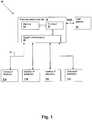
Figure 1 , anIP telephone system 10 in accordance with an embodiment of the present invention is shown. The depicted embodiment is not intended to be limiting, but only exemplary of the type of telephone system to which the methods and structures of the present invention may be applied. - The
IP telephone system 10 has one or moredesktop IP telephones 11A-11D coupled to an IP phonecentral controller 12 by individual local-area network (LAN)connections 16. TheLAN connection 16 may be 10/100, gigabit connection, or the like. TheLAN connection 16 is in turn coupled to a wide-area network (WAN) connection WAN, through which a remote gateway such as a voice-over Internet protocol (VOIP)gateway 18 can be addressed. Program instructions are provided to implement software algorithms and are stored within amemory 14 of IP phonecentral controller 12. The program instructions are executed by aprocessor 13, to provide such functions as a scheduler and messaging functionality as described in further detail below, by communicating withIP telephones 11A-11D viaLAN interfaces 15. TheLAN interface 15 may be 10/100, Gigabit (10/100/1000) LAN interface, or the like. - Referring now to
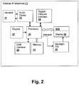
Figure 2 , thedesktop IP telephone 11 is controlled by aprocessor 20. Theprocessor 20 executes program code stored inmemory 22 to provide various functions of thedesktop IP telephone 11. The depicted example is only illustrative and multiple processors may be provided for different functions within thedesktop IP telephone 11. However, a single processor implementation has been shown for clarity. Ahandset 21 may be interfaced through anaudio codec circuit 23 to theprocessor 20. Audio information received from a microphone in thehandset 21 may be converted by theaudio codec 23 to information that can be communicated over a Local Area Network (LAN) connected to the Ethernetinterface 25. Information received from the Ethernetinterface 25 is also converted by theaudio codec 23 to audio signals which are provided to an output transducer (speaker) of thehandset 21.Processor 20 in combination withaudio codec 23, implements a protocol such as Session Initiation Protocol (SIP) or other proprietary protocol to support a telephone connection between VOIP gateway and thedesktop IP telephone 11. Processor 20 may also control energy management states within thedesktop IP telephone 11. This may include such things as disabling abacklight power supply 26 that provides power to a backlight within thedisplay 24 and sending commands to the Ethernetinterface 25 to place the Ethernetinterface 25 and the connection in a power-down state.- The
processor 20 may further control other power down functions including, but not limited to, disabling thedisplay driver circuitry 24A to remove any information/text on theLCD display 24 itself, powering down LED indicators (such as message waiting indicator), powering down audio circuitry including a digital signal processor, etc. - The
desktop IP telephone 11 may further have anLCD display 24. TheLCD display 24 may be used to display a variety of calling and messaging information to the user. TheLCD display 24 on the telephones further provide expanded programmable options for the telephones such as self labeling keys and the like. TheLCD display 24 may be coupled to adisplay driver circuitry 24A which may be coupled to theprocessor 20. Thedisplay driver circuitry 24A may receive commands from theprocessor 20 to control operation of theLCD display 24. Desktop IP telephone 11 may also include akeypad 27 for providing standard and special telephone button functionality. For example, thekeypad 27 may have a button for call forwarding, call transfer, placing a caller on hold, intercom features, placing thedesktop IP telephone 11 in an energy savings mode, and the like. The listing of the above is given as an example and should not be seen in a limiting scope.Desktop IP telephone 11 may also include a USB interface 28 or another suitable interface. The USB interface 28 may be used as interface through which a connection can be established to another device such as personal computer, in order to receive proximity or absence indications. Such indications can also be provided via packets received at the Ethernetinterface 25 that originate over a network connection of the personal computer or from a service with which personal computer is interacting, such as an Internet messaging service.Desktop IP telephone 11 may implement at least one low power operating mode. The low power operating mode may include a deep sleep mode of operation in which Ethernetinterface 25,display 24,backlight power supply 26,audio codec 23, and LED indicators are disabled and a light sleep mode of operation wherein the displaybacklight power supply 26,audio codec 23, and optionallyLCD display 24 are de-activated, but EthernetInterface 25 is maintained in an active state. Thekeypad 27 may be scanned to determine if buttons are pressed (including the hook switch activated by handset 21) andprocessor 20 will generally enter periodic idle or sleep modes except when detecting activity, or when a wakeup timer has elapsed.- Referring now to
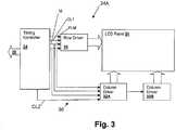
Figure 3 , a detailed view of thedisplay driver circuitry 24A is shown. Thedisplay driver circuitry 24A may have arow driver 30 and a column driver 32. In accordance with one embodiment, the column driver 32 is comprised of an evennumber column driver 32A and an oddnumber column driver 32B. Therow driver 30 and the column driver 32 may be used for outputting display data at a specified location on thedisplay 24. - The
row driver 30 and the column driver 32 may be coupled to atiming controller 34. In the present embodiment, a plurality ofsignal lines 36 may be used to couple therow driver 30 and the column driver 32 to thetiming controller 34. Thetiming controller 34 may also be coupled to theprocessor 20. Thetiming controller 34 receives the image data to be shown on thedisplay 24 and outputs row control signals, column control signals and pixel data. Therow driver 30 receives the row control signals and outputs row driving signals to theLCD panel 24. The column driver 32 receives the column control signals and outputs column driving signals to theLCD panel 24. TheLCD panel 24 displays pixel data according to the row driving signals and column driving signals respectively. - In accordance with one embodiment, the
signal lines 36 may include, but are not limited to: a First Line Marker (FLM) signal which may be sent at the start of every display frame; CL1 signal which may be a data latch signal, CL2 signal which may be a data shift signal or clock signal; M signal which may be a square wave of approximately 50% duty cycle which is used by theLCD panel 24 to switch the polarity of the display driver voltage to ensure there is no DC component applied across the liquid crystal cell; and data lines. Some of thesignal lines 36 may be coupled to both therow driver 30 and the column driver 32. Whileother signal lines 36 may be coupled just to therow driver 30 or the column driver 32. - Presently, most
desktop IP telephone 11 use a clock signal (hereinafter M signal as described above) to drive theLCD panel 24. The M signal is set at a fixed frequency F1. TheLCD panel 24 will operate at this fixed frequency F1 regardless of whether thedesktop IP telephone 11 is in an active state or in a low power operating mode. In general, the fixed frequency F1 is typically half the FLM refresh rate of theLCD panel 24. - As stated above, the
LCD panel 24 may exhibit localized dark spots on theLCD panel 24. Once the dark spots appear on theLCD panel 24, there presently is no practical way of removing them. The dark spots are caused by stray ions migrating within the LC fluid to localized areas. - It has been discovered that the likelihood of dark spots that appear on the
LCD panel 24 is inversely proportional to the operating frequency of the M signal of theLCD panel 24. Under certain conditions, the lateral ion speed can be maximized, and the ions may be swept away clearing the localized dark spots on theLCD panel 24. By adjusting the frequency used to drive theLCD panel 24, the ions are prevented from pooling thereby clearing the localized dark spots on theLCD panel 24. - In accordance with one embodiment of the present invention, the
timing controller 34 may provide dynamic frequency control for driving theLCD panel 24. This may allow thetiming controller 34 to change the frequency used for driving theLCD panel 24. Thus, thetiming controller 34 may alter the M signal from the normal operating frequency F1 to a second frequency F2. TheLCD panel 24 will then be driven at this second frequency F2 for a predetermined time frame. By operating theLCD panel 24 at the second frequency F2, one may maximize the lateral ion speed, and the ions may be swept away clearing the localized dark spots on theLCD panel 24. The second frequency F2 is generally a frequency higher than F1. - Operating the
LCD panel 24 at the higher frequency F2 may increase the power consumption of theLCD panel 24. It may further reduce the contrast ratio of theLCD panel 24. Thus, it may be desirable to drive theLCD panel 24 at the second frequency F2 during the low power operating mode of thedesktop IP telephone 11 such as a sleep mode, a screen saver mode, or the like. - The
LCD panel 24 may be driven at the frequency F1 for times when thedesktop IP telephone 11 is in an active state and at the frequency F2 for the times thedesktop IP telephone 11 is in an inactive state or low power operating mode (hereinafter "inactive" state). For example, the "active" operating state of thedesktop IP telephone 11 may be defined as the times when the backlight of theLCD panel 24 is operating at user defined maximum intensity. The "idle" state may be defined as the time when the backlight is operating at user defined minimum intensity. Thetiming controller 34 may signal frequency changes in response to the defined "active" and "inactive" states. Alternatively, when a user answers a call, or dials a phone number, theLCD panel 24 is in a state where information is changing in response to user interaction and this "active" state is the one which would use the normal operating frequency F1. When thedesktop IP telephone 11 is idle, or unattended for long periods of time, theLCD panel 24 may be considered in an "inactive" state and could be adjusted to be driven at the second frequency F2 to take advantage of the restorative effects. The "active" and "inactive" states may be user defined. Thus, the above description is given only as examples. TheLCD panel 24 may be driven at the frequency F2 at other times without departing from the spirit and scope of the present invention. - Referring now to
Figure 4 , a method of removing the localized dark spots on theLCD panel 24 of thedesktop IP telephone 11 ofFigure 1 is shown. TheIP telephone 11 is initially powered-up (Step 40). Next, the network (LAN) interface of thedesktop IP telephone 11 is initialized and connections are established to an IP phone central controller 12 (Step 41). Upon initial power-on and connection to the IP phonecentral controller 12, any configuration (and/or program code) that is loaded from IP phonecentral controller 12 is downloaded to thedesktop IP telephone 11. - At predetermined time frames, the
processor 20 may send a signal to thetiming controller 34 to set the M signal used to drive the LCD panel 24 (Step 42). Thetiming controller 34 may set the M signal to run at the normal operating frequency F1 or at the second frequency F2. The second frequency F2 is generally a frequency higher than F1. Thetiming controller 34 may set the frequency in response to defined "active" and "inactive" states. The "active" and "inactive" states may be pre-determined for thedesktop IP telephone 11 by simply associating them with the times when the backlight of theLCD panel 24 is driven to the customer selected setting. - The
processor 20 may be used to determine when thetiming controller 34 sends a signal to alter the clock signal C2 used to drive theLCD panel 24. Theprocessor 20 may be used to determine the "active" and "inactive" states (decision 43). If theprocessor 20 determines thedesktop IP telephone 11 is in an "active" state, theLCD panel 24 will be driven at the frequency F1 (Step 44). If theprocessor 20 determines that thedesktop IP telephone 11 is in an "inactive" state, theLCD panel 34 will be driven at the frequency F2 (Step 45). - The
desktop IP telephone 11 provides for dynamic frequency control for driving theLCD panel 24. Thedesktop IP telephone 11 allows for the changing of the frequency of the M signal in sync with the operating state of thedesktop IP telephone 11. By providing a means for driving theLCD panel 24 at a second higher frequency, thedesktop IP phone 11 has the ability to reverse any build up of ions that are present in the LC fluid from forming dark smudges in the active area of theLCD panel 24.
Claims (7)
- A desktop network protocol telephone set (11), comprising:a network interface (25) for connecting the telephone set to a local area network;an audio interface (23) for providing audio signals to and from a handset (21) of the telephone set;a processing circuit (20) responsive to communications from the network interface; anda control circuit (24A) for changing a driving frequency of a clock signal used to drive an LCD panel (24) of the telephone set based on an operating mode of the telephone set, wherein the driving frequency of the clock signal is at a first driving frequency during a full power operating mode of the telephone set and at a second, higher, driving frequency during a low power operating mode of the telephone set.
- The desktop network protocol telephone set of claim 1, wherein the low power operating mode is when a backlight (26) of the LCD panel is operating at a user defined minimum intensity.
- The desktop network protocol telephone set of claim 1, wherein the low power operating mode occurs when the telephone set is unattended for a predetermined period of time.
- The desktop network protocol telephone set of claim 1, wherein the low power operating is user defined.
- A method of operation of a desktop network protocol telephone set (11) coupled to a local area network by a network interface, comprising:first receiving first network transmissions from the local area network corresponding to received audio signals;first converting the first network transmissions to a first audio signal provided to a handset (21) of the telephone set;second receiving a second audio signal from the handset;second converting the second audio signal to second network transmissions and providing them to the network interface;determining an operating mode of the telephone set; andsetting a frequency of a clock signal driving an LCD panel of the telephone based on an operating mode of the telephone, wherein the frequency of the clock signal is at first driving frequency during a full power operating mode of the telephone set and at a second, higher, driving frequency during a low power operating mode of the telephone set.
- The method of claim 5, wherein the low power operating mode is when a backlight of the LCD panel is operating at a user defined minimum intensity.
- The method of claim 5, wherein the full power operating mode is when a backlight of the LCD panel is operating at a user defined maximum intensity.
Applications Claiming Priority (1)
| Application Number | Priority Date | Filing Date | Title |
|---|---|---|---|
| US12/583,343US8526584B2 (en) | 2009-08-18 | 2009-08-18 | Device and method for preventing ion build-up in liquid crystal displays |
Publications (2)
| Publication Number | Publication Date |
|---|---|
| EP2287831A1 EP2287831A1 (en) | 2011-02-23 |
| EP2287831B1true EP2287831B1 (en) | 2019-03-27 |
Family
ID=42691150
Family Applications (1)
| Application Number | Title | Priority Date | Filing Date |
|---|---|---|---|
| EP10154634.9AActiveEP2287831B1 (en) | 2009-08-18 | 2010-02-25 | Device and method for preventing ion build-up in liquid crystal displays |
Country Status (4)
| Country | Link |
|---|---|
| US (1) | US8526584B2 (en) |
| EP (1) | EP2287831B1 (en) |
| CN (1) | CN101998000A (en) |
| CA (1) | CA2703713C (en) |
Families Citing this family (4)
| Publication number | Priority date | Publication date | Assignee | Title |
|---|---|---|---|---|
| US9762748B2 (en)* | 2009-06-08 | 2017-09-12 | Mitel Networks Corporation | Power management in an internet protocol (IP) telephone |
| KR101797523B1 (en)* | 2011-05-23 | 2017-11-15 | 삼성전자 주식회사 | The display apparatus and control method thereof |
| US9288616B2 (en)* | 2013-10-10 | 2016-03-15 | Pushd, Inc. | Automated electronic reminders for a mobile user |
| KR20240120075A (en)* | 2023-01-31 | 2024-08-07 | 엘지디스플레이 주식회사 | Display Device Having Improved Response Property And Method Of Driving The Same |
Family Cites Families (11)
| Publication number | Priority date | Publication date | Assignee | Title |
|---|---|---|---|---|
| US5633651A (en)* | 1994-11-04 | 1997-05-27 | Texas Instruments Incorporated | Automatic bidirectional indicator driver |
| US6507330B1 (en) | 1999-09-01 | 2003-01-14 | Displaytech, Inc. | DC-balanced and non-DC-balanced drive schemes for liquid crystal devices |
| KR100369939B1 (en)* | 2000-12-27 | 2003-01-29 | 한국전자통신연구원 | Method of an Automatic IPv6 Address Generation and IP Address Lookup by using E.164 Telephone Numbers |
| JP2002237886A (en)* | 2001-02-09 | 2002-08-23 | Fujitsu Ltd | Apparatus and method for reducing power in portable terminal with display device |
| JP2007504488A (en) | 2003-08-28 | 2007-03-01 | コーニンクレッカ フィリップス エレクトロニクス エヌ ヴィ | Lateral ion pumping in liquid crystal displays |
| CN1564594A (en)* | 2004-03-25 | 2005-01-12 | 张健 | Visual telephone compatible public telephone switched network with protocal network of internet |
| JP2006039337A (en)* | 2004-07-29 | 2006-02-09 | Nec Electronics Corp | Liquid crystal display and driving circuit thereof |
| US20080037518A1 (en) | 2006-07-26 | 2008-02-14 | Parameswaran Kumarasamy | Method and apparatus for voice over internet protocol call signaling and media tracing |
| TWI336874B (en) | 2007-03-12 | 2011-02-01 | Au Optronics Corp | Drive circuit, display apparatus, and method for adjusting screen refresh rate |
| KR101301394B1 (en) | 2008-04-30 | 2013-08-28 | 엘지디스플레이 주식회사 | Liquid Crystal Display and Driving Method thereof |
| US20090290698A1 (en)* | 2008-05-23 | 2009-11-26 | Sony Ericsson Mobile Communications Ab | Method and device for transmitting voice data in a communication network |
- 2009
- 2009-08-18USUS12/583,343patent/US8526584B2/enactiveActive
- 2010
- 2010-02-25EPEP10154634.9Apatent/EP2287831B1/enactiveActive
- 2010-03-31CNCN2010101513158Apatent/CN101998000A/enactivePending
- 2010-05-13CACA2703713Apatent/CA2703713C/enactiveActive
Non-Patent Citations (1)
| Title |
|---|
| None* |
Also Published As
| Publication number | Publication date |
|---|---|
| CA2703713C (en) | 2014-05-27 |
| CA2703713A1 (en) | 2011-02-18 |
| CN101998000A (en) | 2011-03-30 |
| EP2287831A1 (en) | 2011-02-23 |
| US20110044441A1 (en) | 2011-02-24 |
| US8526584B2 (en) | 2013-09-03 |
Similar Documents
| Publication | Publication Date | Title |
|---|---|---|
| US7391164B2 (en) | Visual notification methods for candy-bar type cellphones | |
| CA2701280C (en) | Power management in an internet protocol (ip) telephone | |
| US6141568A (en) | Battery saving in portable radio apparatus | |
| KR100613667B1 (en) | Display device and control system related thereto | |
| EP2287831B1 (en) | Device and method for preventing ion build-up in liquid crystal displays | |
| US8129925B2 (en) | Terminal device and computer-readable storage medium | |
| CN105096845A (en) | Display control method of display screen, and display screen | |
| US20100110054A1 (en) | Display module and method for using the same | |
| WO2008047568A1 (en) | Display method, display system, mobile communication terminal, and display controller | |
| CN101409774A (en) | Television set | |
| CN103514837A (en) | Terminal screen backlight control method and apparatus | |
| CN210606394U (en) | OLED electronic couplet | |
| CA2518006C (en) | Visual notification methods for candy-bar type cellphones | |
| CA2383394C (en) | System and method for reducing power consumption by a liquid crystal display | |
| US20060052079A1 (en) | Method for controlling the power consumption in an electronic appliance | |
| CN101409056B (en) | Half-transmissive half-reflective liquid crystal display device and driving control method thereof | |
| US20150049755A1 (en) | Power Management in an Internet Protocol (IP) Telephone | |
| US20100069124A1 (en) | Mobile communication device and an incoming caller number prompt method thereof | |
| JPH09218669A (en) | Image display device | |
| CN109413280A (en) | A kind of information prompting method and device | |
| KR20040054118A (en) | Method for controlling power of mobile communication terminal | |
| KR20040043495A (en) | mobile communication terminal having a power control function of the LCD backlight and controlling method therefore | |
| HK1088977A (en) | Visual notification methods for mobilephones | |
| JP5536253B1 (en) | Button telephone system, control method, terminal, and program | |
| JPH02100447A (en) | telephone |
Legal Events
| Date | Code | Title | Description |
|---|---|---|---|
| PUAI | Public reference made under article 153(3) epc to a published international application that has entered the european phase | Free format text:ORIGINAL CODE: 0009012 | |
| AK | Designated contracting states | Kind code of ref document:A1 Designated state(s):AT BE BG CH CY CZ DE DK EE ES FI FR GB GR HR HU IE IS IT LI LT LU LV MC MK MT NL NO PL PT RO SE SI SK SM TR | |
| AX | Request for extension of the european patent | Extension state:AL BA RS | |
| 17P | Request for examination filed | Effective date:20110726 | |
| STAA | Information on the status of an ep patent application or granted ep patent | Free format text:STATUS: EXAMINATION IS IN PROGRESS | |
| 17Q | First examination report despatched | Effective date:20171130 | |
| GRAP | Despatch of communication of intention to grant a patent | Free format text:ORIGINAL CODE: EPIDOSNIGR1 | |
| STAA | Information on the status of an ep patent application or granted ep patent | Free format text:STATUS: GRANT OF PATENT IS INTENDED | |
| INTG | Intention to grant announced | Effective date:20181123 | |
| GRAS | Grant fee paid | Free format text:ORIGINAL CODE: EPIDOSNIGR3 | |
| GRAA | (expected) grant | Free format text:ORIGINAL CODE: 0009210 | |
| STAA | Information on the status of an ep patent application or granted ep patent | Free format text:STATUS: THE PATENT HAS BEEN GRANTED | |
| AK | Designated contracting states | Kind code of ref document:B1 Designated state(s):AT BE BG CH CY CZ DE DK EE ES FI FR GB GR HR HU IE IS IT LI LT LU LV MC MK MT NL NO PL PT RO SE SI SK SM TR | |
| REG | Reference to a national code | Ref country code:GB Ref legal event code:FG4D | |
| REG | Reference to a national code | Ref country code:CH Ref legal event code:EP | |
| REG | Reference to a national code | Ref country code:AT Ref legal event code:REF Ref document number:1113986 Country of ref document:AT Kind code of ref document:T Effective date:20190415 | |
| REG | Reference to a national code | Ref country code:IE Ref legal event code:FG4D | |
| REG | Reference to a national code | Ref country code:DE Ref legal event code:R096 Ref document number:602010057777 Country of ref document:DE | |
| PG25 | Lapsed in a contracting state [announced via postgrant information from national office to epo] | Ref country code:FI Free format text:LAPSE BECAUSE OF FAILURE TO SUBMIT A TRANSLATION OF THE DESCRIPTION OR TO PAY THE FEE WITHIN THE PRESCRIBED TIME-LIMIT Effective date:20190327 Ref country code:LT Free format text:LAPSE BECAUSE OF FAILURE TO SUBMIT A TRANSLATION OF THE DESCRIPTION OR TO PAY THE FEE WITHIN THE PRESCRIBED TIME-LIMIT Effective date:20190327 Ref country code:NO Free format text:LAPSE BECAUSE OF FAILURE TO SUBMIT A TRANSLATION OF THE DESCRIPTION OR TO PAY THE FEE WITHIN THE PRESCRIBED TIME-LIMIT Effective date:20190627 Ref country code:SE Free format text:LAPSE BECAUSE OF FAILURE TO SUBMIT A TRANSLATION OF THE DESCRIPTION OR TO PAY THE FEE WITHIN THE PRESCRIBED TIME-LIMIT Effective date:20190327 | |
| REG | Reference to a national code | Ref country code:NL Ref legal event code:MP Effective date:20190327 | |
| PG25 | Lapsed in a contracting state [announced via postgrant information from national office to epo] | Ref country code:HR Free format text:LAPSE BECAUSE OF FAILURE TO SUBMIT A TRANSLATION OF THE DESCRIPTION OR TO PAY THE FEE WITHIN THE PRESCRIBED TIME-LIMIT Effective date:20190327 Ref country code:LV Free format text:LAPSE BECAUSE OF FAILURE TO SUBMIT A TRANSLATION OF THE DESCRIPTION OR TO PAY THE FEE WITHIN THE PRESCRIBED TIME-LIMIT Effective date:20190327 Ref country code:GR Free format text:LAPSE BECAUSE OF FAILURE TO SUBMIT A TRANSLATION OF THE DESCRIPTION OR TO PAY THE FEE WITHIN THE PRESCRIBED TIME-LIMIT Effective date:20190628 Ref country code:BG Free format text:LAPSE BECAUSE OF FAILURE TO SUBMIT A TRANSLATION OF THE DESCRIPTION OR TO PAY THE FEE WITHIN THE PRESCRIBED TIME-LIMIT Effective date:20190627 Ref country code:NL Free format text:LAPSE BECAUSE OF FAILURE TO SUBMIT A TRANSLATION OF THE DESCRIPTION OR TO PAY THE FEE WITHIN THE PRESCRIBED TIME-LIMIT Effective date:20190327 | |
| REG | Reference to a national code | Ref country code:AT Ref legal event code:MK05 Ref document number:1113986 Country of ref document:AT Kind code of ref document:T Effective date:20190327 | |
| PG25 | Lapsed in a contracting state [announced via postgrant information from national office to epo] | Ref country code:ES Free format text:LAPSE BECAUSE OF FAILURE TO SUBMIT A TRANSLATION OF THE DESCRIPTION OR TO PAY THE FEE WITHIN THE PRESCRIBED TIME-LIMIT Effective date:20190327 Ref country code:PT Free format text:LAPSE BECAUSE OF FAILURE TO SUBMIT A TRANSLATION OF THE DESCRIPTION OR TO PAY THE FEE WITHIN THE PRESCRIBED TIME-LIMIT Effective date:20190727 Ref country code:SK Free format text:LAPSE BECAUSE OF FAILURE TO SUBMIT A TRANSLATION OF THE DESCRIPTION OR TO PAY THE FEE WITHIN THE PRESCRIBED TIME-LIMIT Effective date:20190327 Ref country code:CZ Free format text:LAPSE BECAUSE OF FAILURE TO SUBMIT A TRANSLATION OF THE DESCRIPTION OR TO PAY THE FEE WITHIN THE PRESCRIBED TIME-LIMIT Effective date:20190327 Ref country code:RO Free format text:LAPSE BECAUSE OF FAILURE TO SUBMIT A TRANSLATION OF THE DESCRIPTION OR TO PAY THE FEE WITHIN THE PRESCRIBED TIME-LIMIT Effective date:20190327 Ref country code:EE Free format text:LAPSE BECAUSE OF FAILURE TO SUBMIT A TRANSLATION OF THE DESCRIPTION OR TO PAY THE FEE WITHIN THE PRESCRIBED TIME-LIMIT Effective date:20190327 Ref country code:IT Free format text:LAPSE BECAUSE OF FAILURE TO SUBMIT A TRANSLATION OF THE DESCRIPTION OR TO PAY THE FEE WITHIN THE PRESCRIBED TIME-LIMIT Effective date:20190327 | |
| PG25 | Lapsed in a contracting state [announced via postgrant information from national office to epo] | Ref country code:SM Free format text:LAPSE BECAUSE OF FAILURE TO SUBMIT A TRANSLATION OF THE DESCRIPTION OR TO PAY THE FEE WITHIN THE PRESCRIBED TIME-LIMIT Effective date:20190327 Ref country code:PL Free format text:LAPSE BECAUSE OF FAILURE TO SUBMIT A TRANSLATION OF THE DESCRIPTION OR TO PAY THE FEE WITHIN THE PRESCRIBED TIME-LIMIT Effective date:20190327 | |
| PG25 | Lapsed in a contracting state [announced via postgrant information from national office to epo] | Ref country code:IS Free format text:LAPSE BECAUSE OF FAILURE TO SUBMIT A TRANSLATION OF THE DESCRIPTION OR TO PAY THE FEE WITHIN THE PRESCRIBED TIME-LIMIT Effective date:20190727 Ref country code:AT Free format text:LAPSE BECAUSE OF FAILURE TO SUBMIT A TRANSLATION OF THE DESCRIPTION OR TO PAY THE FEE WITHIN THE PRESCRIBED TIME-LIMIT Effective date:20190327 | |
| REG | Reference to a national code | Ref country code:DE Ref legal event code:R097 Ref document number:602010057777 Country of ref document:DE | |
| PG25 | Lapsed in a contracting state [announced via postgrant information from national office to epo] | Ref country code:DK Free format text:LAPSE BECAUSE OF FAILURE TO SUBMIT A TRANSLATION OF THE DESCRIPTION OR TO PAY THE FEE WITHIN THE PRESCRIBED TIME-LIMIT Effective date:20190327 | |
| PLBE | No opposition filed within time limit | Free format text:ORIGINAL CODE: 0009261 | |
| STAA | Information on the status of an ep patent application or granted ep patent | Free format text:STATUS: NO OPPOSITION FILED WITHIN TIME LIMIT | |
| PG25 | Lapsed in a contracting state [announced via postgrant information from national office to epo] | Ref country code:SI Free format text:LAPSE BECAUSE OF FAILURE TO SUBMIT A TRANSLATION OF THE DESCRIPTION OR TO PAY THE FEE WITHIN THE PRESCRIBED TIME-LIMIT Effective date:20190327 | |
| 26N | No opposition filed | Effective date:20200103 | |
| PG25 | Lapsed in a contracting state [announced via postgrant information from national office to epo] | Ref country code:TR Free format text:LAPSE BECAUSE OF FAILURE TO SUBMIT A TRANSLATION OF THE DESCRIPTION OR TO PAY THE FEE WITHIN THE PRESCRIBED TIME-LIMIT Effective date:20190327 | |
| REG | Reference to a national code | Ref country code:CH Ref legal event code:PL | |
| REG | Reference to a national code | Ref country code:DE Ref legal event code:R082 Ref document number:602010057777 Country of ref document:DE Representative=s name:VENNER SHIPLEY GERMANY LLP, DE Ref country code:DE Ref legal event code:R082 Ref document number:602010057777 Country of ref document:DE Representative=s name:VENNER SHIPLEY LLP, DE | |
| REG | Reference to a national code | Ref country code:BE Ref legal event code:MM Effective date:20200229 | |
| PG25 | Lapsed in a contracting state [announced via postgrant information from national office to epo] | Ref country code:MC Free format text:LAPSE BECAUSE OF FAILURE TO SUBMIT A TRANSLATION OF THE DESCRIPTION OR TO PAY THE FEE WITHIN THE PRESCRIBED TIME-LIMIT Effective date:20190327 Ref country code:LU Free format text:LAPSE BECAUSE OF NON-PAYMENT OF DUE FEES Effective date:20200225 | |
| PG25 | Lapsed in a contracting state [announced via postgrant information from national office to epo] | Ref country code:CH Free format text:LAPSE BECAUSE OF NON-PAYMENT OF DUE FEES Effective date:20200229 Ref country code:LI Free format text:LAPSE BECAUSE OF NON-PAYMENT OF DUE FEES Effective date:20200229 | |
| PG25 | Lapsed in a contracting state [announced via postgrant information from national office to epo] | Ref country code:IE Free format text:LAPSE BECAUSE OF NON-PAYMENT OF DUE FEES Effective date:20200225 | |
| PG25 | Lapsed in a contracting state [announced via postgrant information from national office to epo] | Ref country code:BE Free format text:LAPSE BECAUSE OF NON-PAYMENT OF DUE FEES Effective date:20200229 | |
| PG25 | Lapsed in a contracting state [announced via postgrant information from national office to epo] | Ref country code:MT Free format text:LAPSE BECAUSE OF FAILURE TO SUBMIT A TRANSLATION OF THE DESCRIPTION OR TO PAY THE FEE WITHIN THE PRESCRIBED TIME-LIMIT Effective date:20190327 Ref country code:CY Free format text:LAPSE BECAUSE OF FAILURE TO SUBMIT A TRANSLATION OF THE DESCRIPTION OR TO PAY THE FEE WITHIN THE PRESCRIBED TIME-LIMIT Effective date:20190327 | |
| PG25 | Lapsed in a contracting state [announced via postgrant information from national office to epo] | Ref country code:MK Free format text:LAPSE BECAUSE OF FAILURE TO SUBMIT A TRANSLATION OF THE DESCRIPTION OR TO PAY THE FEE WITHIN THE PRESCRIBED TIME-LIMIT Effective date:20190327 | |
| PGFP | Annual fee paid to national office [announced via postgrant information from national office to epo] | Ref country code:FR Payment date:20241231 Year of fee payment:16 | |
| PGFP | Annual fee paid to national office [announced via postgrant information from national office to epo] | Ref country code:DE Payment date:20241231 Year of fee payment:16 | |
| PGFP | Annual fee paid to national office [announced via postgrant information from national office to epo] | Ref country code:GB Payment date:20250102 Year of fee payment:16 |