EP2286782B1 - Hospital bed control apparatus - Google Patents
Hospital bed control apparatusDownload PDFInfo
- Publication number
- EP2286782B1 EP2286782B1EP10176912.3AEP10176912AEP2286782B1EP 2286782 B1EP2286782 B1EP 2286782B1EP 10176912 AEP10176912 AEP 10176912AEP 2286782 B1EP2286782 B1EP 2286782B1
- Authority
- EP
- European Patent Office
- Prior art keywords
- controller
- weight
- sensor
- pressure
- output
- Prior art date
- Legal status (The legal status is an assumption and is not a legal conclusion. Google has not performed a legal analysis and makes no representation as to the accuracy of the status listed.)
- Expired - Lifetime
Links
Images


Classifications
- A—HUMAN NECESSITIES
- A61—MEDICAL OR VETERINARY SCIENCE; HYGIENE
- A61B—DIAGNOSIS; SURGERY; IDENTIFICATION
- A61B5/00—Measuring for diagnostic purposes; Identification of persons
- A61B5/103—Measuring devices for testing the shape, pattern, colour, size or movement of the body or parts thereof, for diagnostic purposes
- A61B5/11—Measuring movement of the entire body or parts thereof, e.g. head or hand tremor or mobility of a limb
- A61B5/1113—Local tracking of patients, e.g. in a hospital or private home
- A61B5/1115—Monitoring leaving of a patient support, e.g. a bed or a wheelchair
- G—PHYSICS
- G01—MEASURING; TESTING
- G01G—WEIGHING
- G01G19/00—Weighing apparatus or methods adapted for special purposes not provided for in the preceding groups
- G01G19/52—Weighing apparatus combined with other objects, e.g. furniture
- A—HUMAN NECESSITIES
- A61—MEDICAL OR VETERINARY SCIENCE; HYGIENE
- A61G—TRANSPORT, PERSONAL CONVEYANCES, OR ACCOMMODATION SPECIALLY ADAPTED FOR PATIENTS OR DISABLED PERSONS; OPERATING TABLES OR CHAIRS; CHAIRS FOR DENTISTRY; FUNERAL DEVICES
- A61G7/00—Beds specially adapted for nursing; Devices for lifting patients or disabled persons
- A61G7/002—Beds specially adapted for nursing; Devices for lifting patients or disabled persons having adjustable mattress frame
- A61G7/005—Beds specially adapted for nursing; Devices for lifting patients or disabled persons having adjustable mattress frame tiltable around transverse horizontal axis, e.g. for Trendelenburg position
- A—HUMAN NECESSITIES
- A61—MEDICAL OR VETERINARY SCIENCE; HYGIENE
- A61G—TRANSPORT, PERSONAL CONVEYANCES, OR ACCOMMODATION SPECIALLY ADAPTED FOR PATIENTS OR DISABLED PERSONS; OPERATING TABLES OR CHAIRS; CHAIRS FOR DENTISTRY; FUNERAL DEVICES
- A61G7/00—Beds specially adapted for nursing; Devices for lifting patients or disabled persons
- A61G7/002—Beds specially adapted for nursing; Devices for lifting patients or disabled persons having adjustable mattress frame
- A61G7/008—Beds specially adapted for nursing; Devices for lifting patients or disabled persons having adjustable mattress frame tiltable around longitudinal axis, e.g. for rolling
- A—HUMAN NECESSITIES
- A61—MEDICAL OR VETERINARY SCIENCE; HYGIENE
- A61G—TRANSPORT, PERSONAL CONVEYANCES, OR ACCOMMODATION SPECIALLY ADAPTED FOR PATIENTS OR DISABLED PERSONS; OPERATING TABLES OR CHAIRS; CHAIRS FOR DENTISTRY; FUNERAL DEVICES
- A61G7/00—Beds specially adapted for nursing; Devices for lifting patients or disabled persons
- A61G7/002—Beds specially adapted for nursing; Devices for lifting patients or disabled persons having adjustable mattress frame
- A61G7/012—Beds specially adapted for nursing; Devices for lifting patients or disabled persons having adjustable mattress frame raising or lowering of the whole mattress frame
- A—HUMAN NECESSITIES
- A61—MEDICAL OR VETERINARY SCIENCE; HYGIENE
- A61G—TRANSPORT, PERSONAL CONVEYANCES, OR ACCOMMODATION SPECIALLY ADAPTED FOR PATIENTS OR DISABLED PERSONS; OPERATING TABLES OR CHAIRS; CHAIRS FOR DENTISTRY; FUNERAL DEVICES
- A61G7/00—Beds specially adapted for nursing; Devices for lifting patients or disabled persons
- A61G7/002—Beds specially adapted for nursing; Devices for lifting patients or disabled persons having adjustable mattress frame
- A61G7/015—Beds specially adapted for nursing; Devices for lifting patients or disabled persons having adjustable mattress frame divided into different adjustable sections, e.g. for Gatch position
- A—HUMAN NECESSITIES
- A61—MEDICAL OR VETERINARY SCIENCE; HYGIENE
- A61G—TRANSPORT, PERSONAL CONVEYANCES, OR ACCOMMODATION SPECIALLY ADAPTED FOR PATIENTS OR DISABLED PERSONS; OPERATING TABLES OR CHAIRS; CHAIRS FOR DENTISTRY; FUNERAL DEVICES
- A61G7/00—Beds specially adapted for nursing; Devices for lifting patients or disabled persons
- A61G7/002—Beds specially adapted for nursing; Devices for lifting patients or disabled persons having adjustable mattress frame
- A61G7/018—Control or drive mechanisms
- A—HUMAN NECESSITIES
- A61—MEDICAL OR VETERINARY SCIENCE; HYGIENE
- A61G—TRANSPORT, PERSONAL CONVEYANCES, OR ACCOMMODATION SPECIALLY ADAPTED FOR PATIENTS OR DISABLED PERSONS; OPERATING TABLES OR CHAIRS; CHAIRS FOR DENTISTRY; FUNERAL DEVICES
- A61G7/00—Beds specially adapted for nursing; Devices for lifting patients or disabled persons
- A61G7/05—Parts, details or accessories of beds
- A61G7/0504—Harnesses or restraining devices in order to evacuate a patient with the mattress, e.g. in situations of emergency, disaster or fire
- A—HUMAN NECESSITIES
- A61—MEDICAL OR VETERINARY SCIENCE; HYGIENE
- A61G—TRANSPORT, PERSONAL CONVEYANCES, OR ACCOMMODATION SPECIALLY ADAPTED FOR PATIENTS OR DISABLED PERSONS; OPERATING TABLES OR CHAIRS; CHAIRS FOR DENTISTRY; FUNERAL DEVICES
- A61G7/00—Beds specially adapted for nursing; Devices for lifting patients or disabled persons
- A61G7/05—Parts, details or accessories of beds
- A61G7/0507—Side-rails
- A61G7/0508—Side-rails characterised by a particular connection mechanism
- A61G7/0509—Side-rails characterised by a particular connection mechanism sliding or pivoting downwards
- A—HUMAN NECESSITIES
- A61—MEDICAL OR VETERINARY SCIENCE; HYGIENE
- A61G—TRANSPORT, PERSONAL CONVEYANCES, OR ACCOMMODATION SPECIALLY ADAPTED FOR PATIENTS OR DISABLED PERSONS; OPERATING TABLES OR CHAIRS; CHAIRS FOR DENTISTRY; FUNERAL DEVICES
- A61G7/00—Beds specially adapted for nursing; Devices for lifting patients or disabled persons
- A61G7/05—Parts, details or accessories of beds
- A61G7/0507—Side-rails
- A61G7/0508—Side-rails characterised by a particular connection mechanism
- A61G7/051—Side-rails characterised by a particular connection mechanism pivoting sideward
- A—HUMAN NECESSITIES
- A61—MEDICAL OR VETERINARY SCIENCE; HYGIENE
- A61G—TRANSPORT, PERSONAL CONVEYANCES, OR ACCOMMODATION SPECIALLY ADAPTED FOR PATIENTS OR DISABLED PERSONS; OPERATING TABLES OR CHAIRS; CHAIRS FOR DENTISTRY; FUNERAL DEVICES
- A61G7/00—Beds specially adapted for nursing; Devices for lifting patients or disabled persons
- A61G7/05—Parts, details or accessories of beds
- A61G7/0507—Side-rails
- A61G7/0512—Side-rails characterised by customised length
- A61G7/0513—Side-rails characterised by customised length covering particular sections of the bed, e.g. one or more partial side-rail sections along the bed
- A61G7/0514—Side-rails characterised by customised length covering particular sections of the bed, e.g. one or more partial side-rail sections along the bed mounted to individual mattress supporting frame sections
- A—HUMAN NECESSITIES
- A61—MEDICAL OR VETERINARY SCIENCE; HYGIENE
- A61G—TRANSPORT, PERSONAL CONVEYANCES, OR ACCOMMODATION SPECIALLY ADAPTED FOR PATIENTS OR DISABLED PERSONS; OPERATING TABLES OR CHAIRS; CHAIRS FOR DENTISTRY; FUNERAL DEVICES
- A61G7/00—Beds specially adapted for nursing; Devices for lifting patients or disabled persons
- A61G7/05—Parts, details or accessories of beds
- A61G7/0527—Weighing devices
- A—HUMAN NECESSITIES
- A61—MEDICAL OR VETERINARY SCIENCE; HYGIENE
- A61G—TRANSPORT, PERSONAL CONVEYANCES, OR ACCOMMODATION SPECIALLY ADAPTED FOR PATIENTS OR DISABLED PERSONS; OPERATING TABLES OR CHAIRS; CHAIRS FOR DENTISTRY; FUNERAL DEVICES
- A61G7/00—Beds specially adapted for nursing; Devices for lifting patients or disabled persons
- A61G7/05—Parts, details or accessories of beds
- A61G7/057—Arrangements for preventing bed-sores or for supporting patients with burns, e.g. mattresses specially adapted therefor
- A61G7/05715—Arrangements for preventing bed-sores or for supporting patients with burns, e.g. mattresses specially adapted therefor with modular blocks, or inserts, with layers of different material
- A—HUMAN NECESSITIES
- A61—MEDICAL OR VETERINARY SCIENCE; HYGIENE
- A61G—TRANSPORT, PERSONAL CONVEYANCES, OR ACCOMMODATION SPECIALLY ADAPTED FOR PATIENTS OR DISABLED PERSONS; OPERATING TABLES OR CHAIRS; CHAIRS FOR DENTISTRY; FUNERAL DEVICES
- A61G7/00—Beds specially adapted for nursing; Devices for lifting patients or disabled persons
- A61G7/05—Parts, details or accessories of beds
- A61G7/057—Arrangements for preventing bed-sores or for supporting patients with burns, e.g. mattresses specially adapted therefor
- A61G7/05769—Arrangements for preventing bed-sores or for supporting patients with burns, e.g. mattresses specially adapted therefor with inflatable chambers
- B—PERFORMING OPERATIONS; TRANSPORTING
- B60—VEHICLES IN GENERAL
- B60B—VEHICLE WHEELS; CASTORS; AXLES FOR WHEELS OR CASTORS; INCREASING WHEEL ADHESION
- B60B33/00—Castors in general; Anti-clogging castors
- B60B33/0002—Castors in general; Anti-clogging castors assembling to the object, e.g. furniture
- B60B33/0015—Castors in general; Anti-clogging castors assembling to the object, e.g. furniture characterised by adaptations made to castor
- B60B33/0021—Castors in general; Anti-clogging castors assembling to the object, e.g. furniture characterised by adaptations made to castor in the form of a mounting pin
- B—PERFORMING OPERATIONS; TRANSPORTING
- B60—VEHICLES IN GENERAL
- B60B—VEHICLE WHEELS; CASTORS; AXLES FOR WHEELS OR CASTORS; INCREASING WHEEL ADHESION
- B60B33/00—Castors in general; Anti-clogging castors
- B60B33/0036—Castors in general; Anti-clogging castors characterised by type of wheels
- B60B33/0042—Double or twin wheels
- B—PERFORMING OPERATIONS; TRANSPORTING
- B60—VEHICLES IN GENERAL
- B60B—VEHICLE WHEELS; CASTORS; AXLES FOR WHEELS OR CASTORS; INCREASING WHEEL ADHESION
- B60B33/00—Castors in general; Anti-clogging castors
- B60B33/0047—Castors in general; Anti-clogging castors characterised by details of the rolling axle
- B60B33/0049—Castors in general; Anti-clogging castors characterised by details of the rolling axle the rolling axle being horizontal
- B—PERFORMING OPERATIONS; TRANSPORTING
- B60—VEHICLES IN GENERAL
- B60B—VEHICLE WHEELS; CASTORS; AXLES FOR WHEELS OR CASTORS; INCREASING WHEEL ADHESION
- B60B33/00—Castors in general; Anti-clogging castors
- B60B33/0047—Castors in general; Anti-clogging castors characterised by details of the rolling axle
- B60B33/0057—Castors in general; Anti-clogging castors characterised by details of the rolling axle the rolling axle being offset from swivel axis
- B—PERFORMING OPERATIONS; TRANSPORTING
- B60—VEHICLES IN GENERAL
- B60B—VEHICLE WHEELS; CASTORS; AXLES FOR WHEELS OR CASTORS; INCREASING WHEEL ADHESION
- B60B33/00—Castors in general; Anti-clogging castors
- B60B33/006—Castors in general; Anti-clogging castors characterised by details of the swivel mechanism
- B60B33/0065—Castors in general; Anti-clogging castors characterised by details of the swivel mechanism characterised by details of the swivel axis
- B60B33/0068—Castors in general; Anti-clogging castors characterised by details of the swivel mechanism characterised by details of the swivel axis the swivel axis being vertical
- B—PERFORMING OPERATIONS; TRANSPORTING
- B60—VEHICLES IN GENERAL
- B60B—VEHICLE WHEELS; CASTORS; AXLES FOR WHEELS OR CASTORS; INCREASING WHEEL ADHESION
- B60B33/00—Castors in general; Anti-clogging castors
- B60B33/006—Castors in general; Anti-clogging castors characterised by details of the swivel mechanism
- B60B33/0065—Castors in general; Anti-clogging castors characterised by details of the swivel mechanism characterised by details of the swivel axis
- B60B33/0073—Castors in general; Anti-clogging castors characterised by details of the swivel mechanism characterised by details of the swivel axis the swivel axis being symmetrical to wheel or wheels
- B—PERFORMING OPERATIONS; TRANSPORTING
- B60—VEHICLES IN GENERAL
- B60B—VEHICLE WHEELS; CASTORS; AXLES FOR WHEELS OR CASTORS; INCREASING WHEEL ADHESION
- B60B33/00—Castors in general; Anti-clogging castors
- B60B33/02—Castors in general; Anti-clogging castors with disengageable swivel action, i.e. comprising a swivel locking mechanism
- B60B33/021—Castors in general; Anti-clogging castors with disengageable swivel action, i.e. comprising a swivel locking mechanism combined with braking of castor wheel
- G—PHYSICS
- G01—MEASURING; TESTING
- G01G—WEIGHING
- G01G19/00—Weighing apparatus or methods adapted for special purposes not provided for in the preceding groups
- G01G19/44—Weighing apparatus or methods adapted for special purposes not provided for in the preceding groups for weighing persons
- G01G19/445—Weighing apparatus or methods adapted for special purposes not provided for in the preceding groups for weighing persons in a horizontal position
- G—PHYSICS
- G01—MEASURING; TESTING
- G01G—WEIGHING
- G01G23/00—Auxiliary devices for weighing apparatus
- G01G23/18—Indicating devices, e.g. for remote indication; Recording devices; Scales, e.g. graduated
- G01G23/36—Indicating the weight by electrical means, e.g. using photoelectric cells
- G—PHYSICS
- G01—MEASURING; TESTING
- G01G—WEIGHING
- G01G5/00—Weighing apparatus wherein the balancing is effected by fluid action
- G01G5/006—Weighing apparatus wherein the balancing is effected by fluid action with pneumatic means
- G—PHYSICS
- G08—SIGNALLING
- G08B—SIGNALLING OR CALLING SYSTEMS; ORDER TELEGRAPHS; ALARM SYSTEMS
- G08B3/00—Audible signalling systems; Audible personal calling systems
- G08B3/10—Audible signalling systems; Audible personal calling systems using electric transmission; using electromagnetic transmission
- G—PHYSICS
- G08—SIGNALLING
- G08B—SIGNALLING OR CALLING SYSTEMS; ORDER TELEGRAPHS; ALARM SYSTEMS
- G08B5/00—Visible signalling systems, e.g. personal calling systems, remote indication of seats occupied
- G08B5/22—Visible signalling systems, e.g. personal calling systems, remote indication of seats occupied using electric transmission; using electromagnetic transmission
- G08B5/36—Visible signalling systems, e.g. personal calling systems, remote indication of seats occupied using electric transmission; using electromagnetic transmission using visible light sources
- A—HUMAN NECESSITIES
- A61—MEDICAL OR VETERINARY SCIENCE; HYGIENE
- A61G—TRANSPORT, PERSONAL CONVEYANCES, OR ACCOMMODATION SPECIALLY ADAPTED FOR PATIENTS OR DISABLED PERSONS; OPERATING TABLES OR CHAIRS; CHAIRS FOR DENTISTRY; FUNERAL DEVICES
- A61G2203/00—General characteristics of devices
- A61G2203/30—General characteristics of devices characterised by sensor means
- A61G2203/32—General characteristics of devices characterised by sensor means for force
- A—HUMAN NECESSITIES
- A61—MEDICAL OR VETERINARY SCIENCE; HYGIENE
- A61G—TRANSPORT, PERSONAL CONVEYANCES, OR ACCOMMODATION SPECIALLY ADAPTED FOR PATIENTS OR DISABLED PERSONS; OPERATING TABLES OR CHAIRS; CHAIRS FOR DENTISTRY; FUNERAL DEVICES
- A61G2203/00—General characteristics of devices
- A61G2203/30—General characteristics of devices characterised by sensor means
- A61G2203/34—General characteristics of devices characterised by sensor means for pressure
- A—HUMAN NECESSITIES
- A61—MEDICAL OR VETERINARY SCIENCE; HYGIENE
- A61G—TRANSPORT, PERSONAL CONVEYANCES, OR ACCOMMODATION SPECIALLY ADAPTED FOR PATIENTS OR DISABLED PERSONS; OPERATING TABLES OR CHAIRS; CHAIRS FOR DENTISTRY; FUNERAL DEVICES
- A61G2203/00—General characteristics of devices
- A61G2203/30—General characteristics of devices characterised by sensor means
- A61G2203/42—General characteristics of devices characterised by sensor means for inclination
- A—HUMAN NECESSITIES
- A61—MEDICAL OR VETERINARY SCIENCE; HYGIENE
- A61G—TRANSPORT, PERSONAL CONVEYANCES, OR ACCOMMODATION SPECIALLY ADAPTED FOR PATIENTS OR DISABLED PERSONS; OPERATING TABLES OR CHAIRS; CHAIRS FOR DENTISTRY; FUNERAL DEVICES
- A61G2203/00—General characteristics of devices
- A61G2203/30—General characteristics of devices characterised by sensor means
- A61G2203/44—General characteristics of devices characterised by sensor means for weight
- A—HUMAN NECESSITIES
- A61—MEDICAL OR VETERINARY SCIENCE; HYGIENE
- A61G—TRANSPORT, PERSONAL CONVEYANCES, OR ACCOMMODATION SPECIALLY ADAPTED FOR PATIENTS OR DISABLED PERSONS; OPERATING TABLES OR CHAIRS; CHAIRS FOR DENTISTRY; FUNERAL DEVICES
- A61G2203/00—General characteristics of devices
- A61G2203/70—General characteristics of devices with special adaptations, e.g. for safety or comfort
- A61G2203/74—General characteristics of devices with special adaptations, e.g. for safety or comfort for anti-shear when adjusting furniture
- A—HUMAN NECESSITIES
- A61—MEDICAL OR VETERINARY SCIENCE; HYGIENE
- A61G—TRANSPORT, PERSONAL CONVEYANCES, OR ACCOMMODATION SPECIALLY ADAPTED FOR PATIENTS OR DISABLED PERSONS; OPERATING TABLES OR CHAIRS; CHAIRS FOR DENTISTRY; FUNERAL DEVICES
- A61G7/00—Beds specially adapted for nursing; Devices for lifting patients or disabled persons
- A61G7/05—Parts, details or accessories of beds
- A61G7/0506—Head or foot boards
Definitions
- the present inventionrelates generally to hospital beds and, more particularly, to a hospital bed having a force or weight sensor.
- Many hospital bedspermit articulation of their patient support decks for relative positioning or elevation of the head, legs, and feet of a patient to suit various therapeutic needs. Moreover, many hospital beds permit adjustment of their patient support decks from a normal horizontal position to an angled head down or head up position - so called “Trendelenburg” and “reverse Trendelenburg” positions, respectively.
- Some force sensorssuch as load cells of a bed scale, are mounted to a movable frame of a bed instead of a stationary base frame. In such embodiments, when the movable frame is aligned at an angle, the measured weight of the patient is inaccurate because the direction of the weight force is not perpendicular to load cells of the weigh system.
- US 5715548discloses an example of a bed with a built in weigh frame.
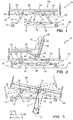
- FIG. 1-3illustrate a hospital bed 10 of the present invention.
- the bed 10illustratively includes a base 12 having a plurality of wheels or casters 14 located on a floor 16.
- a moveable frame 18is coupled to base 12 by a conventional lifting mechanisms 19.
- Frame 18includes a support frame 20 and a weigh frame 22 coupled to support frame 20 by a plurality of load cells 24 in a conventional manner. See, for example, U.S. patent No. 4,953,244 , which is assigned to the assignee of the present invention.
- a support 26is coupled to weigh frame 22.
- An articulating deck 28is coupled to support 26 so that the entire weight of the deck 28 and the patient 42 thereon is supported by the weigh frame 22.
- deck 28includes a head deck section 30, a seat deck section 32, a thigh deck section 34, and a foot deck section 36. These deck sections 30, 32, 34 and 36 are pivotally coupled together to permit articulation of the deck 28 as illustrated in Fig. 2 .
- Mechanisms for moving the various deck sections 30, 32, 34 and 36are well known in the art.
- a patient support 40such as a fluid filled mattress is located on the deck 28 to support the patient 42.
- the patient support 40includes a head zone 44, a seat zone 46, a thigh zone 48, and a foot zone 50.
- the head zone 44, seat zone 46, thigh zone 48, and foot zone 50are independently pressurizable zones.
- a fluid supply 52 and a controlled 54are illustratively coupled to base 12 and to the various zones 44, 46, 48 and 50 of patient support 40 in a conventional manner. Controller 54 therefore adjusts the pressure with in the zones 44, 46, 48 and 50 based on the desired pressure setting characteristics for supporting patient 42.
- fluid supply 52is a blower or compressor used to fill the patient support zones 44, 46, 48, 50 with air, although other types of fluid may be used.
- lifting mechanisms 19provide general raising and lowering of frame 18 relative to base 12. Further, lifting mechanisms 19 provide for positioning of frame 18 (and thus, also patient support deck 28) in Trendelenburg (head down) or reverse Trendelenburg (head up) orientations as shown in Fig. 3 .
- Such types of hospital bed configurationsare well-known.
- the specific lifting mechanisms 19 disclosed hereinare merely exemplary and not limiting to the present invention.
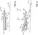
- the weight force Wis conceivable as a sum of component vector forces including a force vector f 1 perpendicular to the weight frame 22 and a second force vector f 2 parallel to the weigh frame 22.
- first force vector f 1has a first magnitude directed at a force angle ⁇ relative to the direction of the weight force W and second force vector f2 has a second magnitude that is directed perpendicular to the direction of first force f 1 .
- force angle ⁇is a complement of the angle between vertical and the plane of seat section 58.
- Load cells 24typically measure only forces which are applied perpendicularly to the weigh frame 22, such as force vector f 1 . Therefore, when a load cell 24 or any other suitable force sensor is positioned to measure and indicate the first force vector f, as the weight of the patient, the measured weight of the patient is inaccurate when the weigh frame 22 is in a Trendelenburg position, a reverse Trendelenburg position, or other angled (non-horizontal) position because the weight force W is not perpendicular to the force sensor.
- a measurement of the force angle ⁇(and a determination of the cosine the force angle ⁇ ) is used to compensate a measurement of the first force f 1 in order to arrive at an actual weight force W (that is, the actual weight of the patient) when the angle of inclination of the weight frame 22 is non-horizontal, typically between the Trendelenburg and reverse Trendelenburg positions.
- angle sensor 58is coupled to movable frame 18 to provide an indication of the angle of the frame.
- angle sensor 58is illustratively an accelerometer, although other sensors may be used.
- the accelerometeris a conventional dual-axis accelerometer.
- the angle sensor 58detects the angle of the movable frame 18 when it is pivoted about a transverse axis such as shown in Fig. 3 .
- the angle sensor 58provides an output signal indicating the angle of movement of movable frame 18 about a longitudinal axis 59 such as during rotational therapy of the patient 42. See, for example, U.S. Patent No.
- a controlleruses output signals from the angle sensor 58 to compensate for the errors created when the movable frame 18 is aligned at a non-horizontal angle.
- a second angle sensor 59is placed on base frame 12.
- a compensationmay be made for unlevel floor 16 to further improve accuracy of the corrected weight signal.
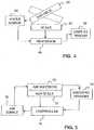
- FIG. 4is a diagrammatical view of an embodiment of the invention.
- a bedhas a bed deck and support frame 60 which are movable to a plurality of angled positions as discussed above.
- hospital bedstypically have a scale 62 such as a series of load cells located beneath a weigh frame. This scale 62 allows caregivers to weigh patients without making them leave the bed.
- Many hospital bedspermit adjustment of a patient support deck and frame 60 from a normal horizontal position to angled head down or head up position - called Trendelenburg and reverse Trendelenburg positions. When the bed deck and frame 60 are aligned at an angle, the measured weight of the patient on the bed is inaccurate due to a cosine error since the load is not perpendicular to the load cells as discussed above.
- an angle sensor 64is coupled to bed deck and/or frame 60. Inputs from angle sensor 64 and bed scale 62 are received by processor 66. An output from processor 66 generates weight output on a display 68. Angle sensor 64 measures the angle of bed deck and frame 60 and outputs a signal corresponding to the angle. Bed scale 62 measures the weight of the bed deck 60 and the patient and outputs a corresponding signal. Processor 66 uses input signals from angle sensors 64 and bed scale 62 to compensate for error introduced in the scale reading when the bed deck 60 is aligned at an angle using the formula discussed above and in more detail below. The processor 66 outputs the corrected patient weight to weight display 68
- a hospital bed 10has a controller which automatically adjusts pressure within a patient support 70 based on a continuous feedback from a scale 72.
- scale 72allows caregivers to weigh patients without making them leave the bed 10. Often the patient's weight is a factor considered when determining optimum air pressure in an air mattress 70 for different size patients.
- Conventional controllersare generally programmed with several weight ranges and corresponding mattress pressures that make the patient more comfortable and reduce pressure on the patient's skin.
- the caregiverinputs the weight of the patient, or presses a button corresponding to a weight range of the patient, and the controller then maintains a predetermined pressure in the air mattress based on the input weight.
- pressure sensors 74measure the air pressure in various zones of air mattress 70.
- An output of pressure sensors 74 and the output of bed scale 72are input into controller 76.
- Controller 76uses the input signals from bed scale 72 to determine the optimum pressure of zones of the air mattress 70 automatically.
- Controller 76uses the input signals from pressure sensors 74 to determine whether the pressure in air mattress *70 needs adjustment.
- the output from controller 76 to air supply 78keeps the air mattress at the desired pressure based on the weight input signal from scale 72.
- Fig. 6is a block diagram of an illustrate patient support pressure control system 200 according to the present invention.
- controller 54 and supply 52operate to adjust one or more pressures within patient support 40 based on the weight of the patient.
- controller 54is a "closed-loop" (or “feedback") type controller constructed from any of various suitable micro-controllers and suitable input-output (“I/O") devices which are well known.
- I/Oinput-output
- Supply 52is illustratively a blower, compressor, pump or other suitable device which is configured in a well known manner to receive control signals from controller 54 and pressurize and provide the compressible medium (discussed above) independently to head zone 44, seat zone 46, thigh zone 48, and foot zone 50 of patient support 40 in response to the control signals.
- supply 52may suitably include valves, pressure regulators, distribution manifolds or the like.
- supply 52includes an input 94 and an output 96.
- Controller 54includes a first cosine generator 98 having an input 102 and an output 106, and a second optional cosine generator 110 having an input 114 and an output 118.
- Each of the cosine generators 98, 110is configured to receive an angle signal (discussed further below) at its respective input and provide at its respective output a cosine signal corresponding to the cosine of the angle represented by the angle signal.
- Controller 54further includes an adjuster 134 having an input 138 and an output 142, and an optional adjuster 146 having an input 150 and an output 154.
- Each of the adjusters 134, 146is configured to suitably amplify or attenuate the signal received at its respective input and provide the resulting signal at its respective output.
- Input 138 of adjuster 134is coupled to output 106 of cosine generator 98 to receive the respective cosine signal (discussed above) therefrom.
- Input 150 of adjuster 146is coupled to output 118 of cosine generator 110 to receive the respective cosine signal (discussed above) therefrom.
- Controller 54further includes a divider 170 having an input 174, inputs 178, and an output 182.
- Divider 170is configured to receive a first signal at input 174, to receive additional signals at each of inputs 178, and to provide at output 182 a signal corresponding to a mathematical division of the signal received at input 174 by all of the signals received at inputs 178.
- One of inputs 178 of divider 170is coupled to output 142 of adjuster 134 to receive the respective signal (discussed above) therefrom.
- Another input 178may be coupled to output 154 of optional adjuster 146 to receive the respective signal (discussed above) therefrom.
- Controller 54further includes a converter 186 having an input 190 and an output 194.
- Converter 186is configured to convert a signal representing the weight of a patient into a signal representing a desired pressure for the various zones 44, 46, 48, 50 of patient support 40. It should be appreciated that the conversion may be may be implemented by a suitable formula of formulate, a suitable lookup table, or a suitable combination thereof for determining an optimum pressure of support 40 based on the patient's weight.
- input 190 of converter 186is coupled to output 182 of divider 170 to receive the respective signal (discussed above) therefrom.
- Controller 54further includes a comparator 198 having an input 202, an input 206, an output 210.
- Comparator 198is configured to receive a signal at input 202, receive a signal at input 206, and provide the difference therebetween at output 210.
- Input 202 of comparator 198is coupled to output 194 of converter 186 to receive the respective desired pressure signal (discussed above) wherefrom,
- Controller 54also includes a compensator 214 having an input 218 and an output 222.
- Compensator 214is suitably configured to move closed-loop parameters of patient support pressure control system 200 into desirable ranges and to provide suitable drive signals to supply 52.
- Input 218 of compensator 214is coupled to output 210 of comparator 198 to receive the respective difference signal (discussed above) therefrom.
- Output 222 of compensator 214is coupled to input 94 of supply 92.
- patient support pressure control system 200further includes at least one pressure sensor 226 having an input 230 and an output 236.
- Pressure sensor 226is configured to be exposed to a pressure of the compressible medium and to generate a pressure signal corresponding thereto.
- pressure sensor 226may be constructed with a suitable strain gage or in any other well known manner. Accordingly, input 230 is coupled a zone 44, 46, 48, 50 of patient support 40 to receive the pressure of the compressible medium herein, and output 236 is coupled to input 206 of comparator 198 to provide the corresponding pressure signal thereto. In the illustrated embodiment, a separate pressure sensor 226 is used for each zone 44, 46, 48, 50.
- Patient support pressure control system 200further includes a force sensor 240 having an input 244 and an output 248.
- Force sensor 240is configured to detect the magnitude of the force f 1 .
- force sensor 240may be implemented with load cells or any other suitable alternative force sensing device. Further, it should be appreciated that force sensor 240 may be implemented as a plurality of individual force sensors, in which case controller 54 processes the force data to derive an aggregate or overall force signal therefrom.
- input 244 of force sensor 240is coupled to weigh frame 22 to detect f 1 .
- force sensor 240may be placed in any number of suitable locations.
- Output 248 of force sensor 240is coupled to input 174 of divider 170 to provide the corresponding pressure signal thereto.
- Angle sensor 252is configured to generate an angle signal corresponding to the angle of the weigh frame 22 when pivoted about an axis transverse to the moveable frame 18 as shown in Fig. 3 . accordingly, angle sensor 252 is coupled to frame 20, weigh frame 22 on deck 28 support to detect angle ⁇ and an output 260 that is coupled to input 102 of cosine generator 98 to provide the corresponding angle signal thereto.
- Angle sensor 252may be implemented with an Orientation Systems type DX-016D-055 tilt sensor, with an Analog Devices ADXL202E accelerometer type tilt sensor, or in any other suitably manner. In any event, various devices for detecting angles using earth magnetic field, accelerometers, inclinometers, drive position monitors, etc. are well-known, and any suitable alternative may be used. Further, it should be readily appreciated that the angle sensor may be located in any number of suitable locations on bed 10.
- Angle sensor 264is configured to generate an angle signal corresponding to an angle of tilt of weigh frame 22 when the moveable frame 18 is pivoted about its longitudinal axis 59. This may be when the frame 18 is rotated to provide lateral rotational therapy to the patient 42. Angle sensor 264 is coupled to support frame 20, weigh frame 22 or deck 28 to detect the angle. An output 272 of sensor 264 is coupled to input 114 of cosine generator 110 to provide the corresponding angle signal thereto. Like angle sensor 252, angle sensor 264 may be implemented with an Orientation Systems type DX-016D-055 tilt sensor, with an Analog Devices ADXL202E tilt sensor, or in any other suitable manner, may be located in any number of suitable locations, and may be implemented as a plurality of separate angle sensors. Illustratively, a single dual axis accelerometer may be used to provide both angle sensors 260 and 264.
- Patient support pressure control system 200also includes a weight display 288 having an input 292.
- Weight display 288is configure to receive a signal corresponding to the weight of the patient and to display of otherwise announce the weight value in a human readable or discernable format as is well known. Accordingly, input 292 of weight display 288 is coupled to output 182 of divider 170 to receive the weight signal wherefrom. Further, it should be readily appreciated that the display of other annunciation device(s) of weight display 288 are suitably positioned on the hospital bed 10 to facilitate reading of the weight information by a user of the present invention.
- Fig. 7is a block diagram of an alternative embodiment of a pressure control system 300 according to the present invention. It should be readily appreciated that the elements of pressure control system 300 are the same as those of pressure control system 200 (discussed above in connection with Fig. 6 ), except pressure control system 300 does not include the angle sensors, cosine generators, adjusters, of divider. Instead, in pressure control system 300, output 248 of force sensor 240 is coupled directly to input 190 of converter 186 and input 292 of weight display 288.
- Fig. 8is a block diagram of a weight display system 400 according to the present invention. It should be readily appreciated that the elements of weight display system 400 are the same as those of pressure control system 200 (discussed above in connection with Fig. 6 ), except weight display system 400 does not "close-the-loop" through the converter, comparator, compensator, or supply.
- Fig. 9is a flow diagram of method of operation 500 for the pressure control system 200.
- Controller 90generates initial control signal(s) for supply 52.
- supply 52pressurizes the zones 44, 46, 48, 50 of patient support 40 with the compressible medium in response to the control signal(s).
- pressure sensor(s) 226generates the pressure signal(s) in response to pressure(s) within patient-support 40.
- force sensor 240generates a force signal(s) in response to the force f 1 (see Fig. 3 , above).
- angle sensor 252(and optional angle sensor 264) generate an angle signal(s) corresponding to angle of alignment of weigh frames 22 about transverse and longitudinal axes.
- weight display 288displays or otherwise announces the weight of the patient (i.e., the weight force W in a human readable or discernable format.
- controller 54generates new control signal(s) for supply 52 in response to the pressure signal(s), the force signal(s), and a cosine of each of the angle signal(s). Steps 520-570 are repeated as necessary to maintain closed-loop control of system 200 as desired,
- controller 54automatically compensate for weight change of the patient by causing supply 52 to increase or decrease pressure within patient support 40 as necessary to maintain desired support characteristics.
- weight display 288indicates the weight of the patient.
- pressure control system 300operation of pressure control system 300 is practically the same as the operation of pressure control system 200 (discussed above) except that in operation of pressure control system 300, the angles of weigh frame 22 are not factored into them closed-loop control of the pressure(s) within patient support 40.
- weight display system 400(see Fig. 8 , above) is practically the same as the operation of pressure control system 200 except that in operation of weight display system 400 the closed-loop control of the pressure(s) within patient support 40 is emitted.
- angle sensor 252may be of conventional design and illustratively include outputs XOUT, YOUT which connect to 2 micro pins each on a microcontroller, or 4 total pins.
- These micro pinsare PCA (programmable counter array) and are interrupt driven. This means that they capture the timing based on a failing or rising edge of the signal coming in.
- the micro pinsgenerate a flag indicating new PCA values in the PCA registers.
- a further illustrative hospital bed 1010including a frame 1012 positioned on the floor 1013, a deck 1014 coupled to the frame 1012, a mattress 1016 positioned on the deck 1014, a headboard 1018 coupled to the frame 1012, a footboard 1020 coupled to the deck 1014, and siderails 1022, 1024 coupled to deck 1014.
- Frame 1012is configured to raise and lower the deck 1014 relative to the floor 1013, while the deck 1014 is configured to articulate to a plurality of positions.
- the deck 1014includes a head section 1026 hingedly connected to a seat section 1028 that is hingedly connected to a foot section 1030.
- the frame 1012 and deck 1014may be of the type disclosed in U.S. Patent No. 5,715,548 , which is assigned to the assignee of the present invention and the disclosure of which is expressly incorporated herein by reference.
- the mattress 1016includes a plurality of sections or zones, illustratively a head section 1032, a seat section 1034, and a foot section 1036 associated with corresponding sections 1026, 1028, and 1030 of the frame 1014. More particularly, each mattress section 1032, 1034, and 1036 is supported by, coupled to, and articulates with the corresponding deck section 1026, 1028, and 1030. Each mattress section 1032, 1034, and 1036 is comprised of at least one corresponding air bladder or cushion 1040, 1042, and 1044 configured to be customizable by inflating to different pressures.
- the patient's weightis a factor considered when determining optimum air pressure in an air mattress for different size patients.
- Conventional controllersare generally programmed with several weight ranges and corresponding mattress pressures that make the patient more comfortable and reduce pressure on the patient's skin.
- the caregiverinputs the weight of the patient, or presses a button corresponding to a weight range of the patient, and the controller then maintains a predetermined pressure in the air mattress based on the input weight.
- a seat force sensor 1029is coupled to the seat section 1028 of the deck 1014.
- the seat force sensor 1029is positioned intermediate the deck 1014 and the mattress 1016 and is configured to detect force or weight applied to the seat section 1034 of the mattress 1016 and output an electrical signal indicative of the detected force.
- the seat force sensor 1029comprises a resistive pressure sensor, although other weight sensors including piezoelectric and capacitor sensors may be substituted therefore.
- a pressure control unit 1038is coupled to the mattress 1016 to independently control the pressures within the air cushions 1040, 1042, and 1044.
- the pressure control unit 1038is illustratively comprised of valves 1046 that regulate the air supplied to the air cushions 1040, 1042, and 1044, pumps or blowers 1048 that pressurize the air to be sent to the air cushions 1040, 1042, and 1044, pressure sensors 1050 configured to measure the pressure within the air cushions 1040, 1042, and 1044, and a controller 1052 configured to determine whether, and to what extent, the pressures within the air cushions 1040, 1042, and 1044 require adjustment.
- the pressure control unit 1038is fluidly connected to the mattress 1016 by air supply hoses 1054, 1056, and 1058, and pressure sensor hoses 1060, 1062, and 1064.
- the pressure control until 1038is electrically connected to the bed 1010 by electrical leads, including a head elevation lead 1066, and a seat force lead 1068.
- the head air cushion 1040is fluidly coupled via the first air supply hose 1054 to the valves 1046 such that the air supply hose 1054 is configured to transfer increases or decreases in pressure from the valves 1046 to the head air cushion 1040.
- Seat air cushion 1042 and foot air cushion 1044are similarly fluidly coupled to the valves 1046 by second and third air supply hoses 1056 and 1058.
- the valves 1046allow for the pressure within each cushion 1040, 1042, and 1044 to be independently controlled. Pressure may be decreased by the valve 1046 releasing pressure to atmosphere.
- Pressuremay be increased by supplying air from the blowers 1048 through the valves 1046, the supply lines 1054, 1056, an 1058 and to the air cushions 1040, 1042, and 1044, respectively:
- each air cushion 1040, 1042, and 1044is configured to be independently pressurized such that pressurization of one cushion 1040, 1042, or 1044 does not necessitate pressurization of the other cushions 1040, 1042, and 1044. Further, pressurization of one cushion 1040, 1042, or 1044 may occur simultaneously with the depressurization of another cushion 1040, 1042, or 1044.
- a first cushion 1040, 1042, or 1044may be depressurized by the valves 1046 diverting pressure from the first cushion 1040, 1042, or 1044 to a second cushion 1040, 1042, or 1044, thereby increasing the pressure of the second cushion 1040, 1042, or 1044.
- An appropriate manifold(not shown) may be utilized to interconnect the air supply hoses 1054, 1056, and 1058 through the valves 1046.
- the controller 1052is preferably electrically coupled to the valves 1046 and blowers 1048.
- the controller 1052is also electrically coupled to the pressure sensors 1050, the seat force sensor 1029 by the seat force lead 1068, and to a head elevation sensor 1070 by the head elevation lead 1066.
- the pressure sensors 1050are coupled to the head, seat, and foot air cushions 1040, 1042, and 1044 to sense the pressure of the air received therein and may be of conventional design.
- the pressure sensors 1050are internal to the pressure control unit 1038 and connected, to the air cushions 1040, 1042, and 1044 via hoses 1060, 1062, and 1064.
- the pressure sensors 1050may be positioned external to the pressure control unit 1038.
- electrical leadsrun from the pressure sensors 1050, located at the respective air cushions 1040, 1042, and 1044, to the controller 1052, located within the pressure control unit 1038.
- the head elevation sensor 1070is configured to measure the angle (A) that the head section 1026 of the deck 1014 forms relative to the floor upon which the bed is placed. As such, the head elevation sensor 1070 is configured to measure the angle (A) of the head section 1026 relative to a substantially horizontal plane. Alternatively, the head elevation sensor 1070 may be configured to measure the angle (B) that the head section 1026 of the deck 1014 forms relative to the frame 1012. While normally the angles (A) and (B) are substantially the same, some variations will exist if the frame 1012 is tilted relative to horizontal.
- a frame angle sensor(not shown) may be associated with the frame 1012 for measuring an angle of the frame 1012 relative to horizontal. As such, compensation may be made for tilting of the frame 1012 from horizontal when measuring the angle (B) between the head section 1026 and the frame 1012.
- the measurement from the head elevation sensor 1070is relayed to the controller 1052 via the head elevation lead 1066.
- the head elevation sensor 1070may comprise any conventional device configured to detect angles including devices using earth magnetic field, accelerometers, inclinometers, drive, position monitors, etc. Further, it should be appreciated that the head elevation sensor 1070 may be located in any number of suitable locations on the bed 1010. Illustratively, the head elevation sensor 1070 may comprise an Orientation Systems type DX-016D-055 tilt sensor of the type described above.
- the seat force sensor 1029is configured to measure the weight supported by the seat section 1028 of the deck 1014. This measurement (F') is relayed to the controller 1052 via the seat force lead 1068.
- the controller 1052receives input from the head elevation sensor 1070 and the seat force sensor 1029 to determine the weight (W) of the patient upon the bed 1010.
- the controller 1652determines, based upon the patient weight (W), the proper baseline pressures P1, P2, and P3 for the air cushions 1040, 1042, and 1044.
- the determination of the weight (W) and proper baseline pressures P1, P2, and P3is illustratively performed by placing the inputs into predetermined formulas or algorithms to calculate the weight (W) and the baseline pressures P1, P2, and P3.
- weight (W) and pressure determinations P1, P2, and P3are performed by comparing the inputs to stored lookup or comparison tables 1078 and 1080 that output the weight (W) and the baseline pressures P1, P2, and P3.
- lookup or comparison tables 1078 and 1080that output the weight (W) and the baseline pressures P1, P2, and P3.
- details of the algorithms and values of the lookup tables 1078 and 1080may be determined based upon patient characteristics and needs.
- the pressures P1, P2, and P3 output by the controller 1052are then compared to the pressures in the cushions 1040, 1042, and 1044 as sensed by the pressure sensors 1050.
- the controller 1052next communicates with the blowers 1048 and valves 1046 to alter the cushion pressures to the pressures output by the controller 1052, as necessary.
- the controller 1052further monitors the seat force (F') and alters the cushion pressures in response to changes in the seat force.
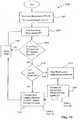
- Fig. 15is a flowchart 1100 of the illustrative method (F') performed by the controller 1052.
- the controller 1052starts at step 1102 by initializing the values for recorded force (F) and tolerance limit (L) to zero.
- the controller 1052proceeds to step 1104 and receives a patient weight measurement (F') from the seat force sensor 1029.
- the next step 1106is to compare (F') to (F). If (F') equals (F), in the initial case meaning that there is no patient within the bed 1010, the controller 1052 cycles through a delay time at block 1108, and then takes another seat force measurement at block 1104.
- the delay time at block 1108can be set to very small intervals such that the cycle back to taking another force measurement at block 1104 can be essentially instantaneous and provide for a substantially constant updating of the seat force measurement (F').
- the limit comparing step 1110compares the measured seat force (F') to the tolerance limits (L).
- Tolerance limits (L)are usually end values of a range of forces that could typically be expected to be produced by a patient with weight (W). During the initial run-through, the weight (W) has not been yet determined, therefore, as the tolerance limits (L) were set to zero in step 1102, the new force (F') is necessarily outside of the limits (L).
- the force measurement (F')is usually only outside of the limits (L) on four occasions: 1) when powered up for the first time, 2) when a second person, such as a visiting relative, sits or otherwise adds weight to the seat section, 3) when the patient leaves the bed, or 4) when the patient gets in the bed.
- the controller 1052proceeds to the head angle measurement step 1112.
- the controller 1052takes input (A) from the head elevation sensor 1070. The controller 1052 then proceeds to the calculation step 1114.
- the calculation step 1114involves the controller 1052 taking the input of the head angle (A) and the seat force measurement (F') to determine the weight (W) and the limits (L) of the range of force measurements associated with the weight (W). This determination is illustratively performed by utilizing the input in algorithms or through the use of a lookup table similar to that illustrated as Table 1 (1078) in Fig. 16 .
- the controller 1052then proceeds to calculation step 1116.
- the calculated weight (W)is taken alone, or in combination with the force measurement (F'), to determine the baseline air cushion pressures P1, P2, and P3. Again, this determination may be performed by using an algorithm or through a lookup table similar to that illustrative as Table 2 (1080) in Fig. 17 .
- the force measurement (F')is next recorded or stored as the current force (F).
- the controller 1052communicates with the valves 1046 and blowers 1048 to set each of the air cushions 1040, 1042, and 1044 to the respective baseline pressures P1, P2, and P3.
- step 1104After the controller 1052 waits out the delay time 1108, another seat force measurement (F') is taken in step 1104. The controller 1052 then proceeds to step 1106. If the patient has shifted within the bed 1010 or the angle of the head section 1026 has been altered, the measured seat force (F') will be different but typically still within the tolerance limits (L). Therefore, when a patient shifts his weight the question of step 1106 is typically answered yes and step 1110 is topically answered no. This causes controller 1052 to proceed to step 1116. Step 1116 takes the new seat force measurement (F'), alone or in combination with the previously determined weight (W), and calculates new air cushion pressures P1, P2, and P3 and adjusts the air cushions 1040, 1042, and 1044 to the new pressures P1, P2, and P3. Also, step 1116 sets and stores the new seat force (F') as the current force (F). The controller 1052 then proceeds to step 1104 after the delay time 1108.
- the processmay proceed directly to the delay time block 1108.
- the controller 1052world not calculate new pressures P1, P2, and P3 nor adjust the pressures in the air cushions 1040, 1042, and 1044 in response thereto. In other words, the controller 1052 would adjust pressures within the air cushions 1040, 1042, and 1044 only when the seat force measurement (F') is outside of then limits (L).
- the head elevation sensor 1070outputs an angle value (A) of substantially zero degrees. Therefore, in step 1114 when determining the weight(W), the controller 1052 takes the measurement from the seat force sensor 1029 and the head section angle of zero to determine the weight (W).
- the weight algorithm and values of Table 1(1078, Fig. 16 ) are determined from known anthropometrical relationships and physics.
- anthropometrical relationshipsallow the controller 1052 to determine the overall weight based upon the weight supported by the seat section 1028 and known body mass relationships:
- the head section 1026assumes an angle (A) relative to the horizontal floor 1013 at the time of weight (W) calculation, physics states that some of the weight normally supported by the head section 1026 when the head section 1026 is lying flat will come to bear upon the seat section 1028. Therefore, anthropometrical relationships along with physics are used to determine the weight (W) of the patient.
- the controller 1052follows steps 1104, 1106, 1110, and 1116 and makes small changes to the pressures P1, P2, and P3 of the air cushions 1040, 1042, and 1044 to compensate for the shift of weight. Alternatively, as noted above, such changes may be ignored by the controller 1052 in order to avoid making such small changes to the pressures P1, P2, and P3.
- a hospital bed 1010'includes a controller 1052' which automatically adjusts pressure within a patient support 16 based on a continuous feedback from a scale 1120.
- the scale 1120illustratively is coupled to the frame 1012 through a plurality of load cells (not shown) and allows caregivers to weigh patients without making them leave the bed. Additional details regarding the scale 1120 are provided in U.S. Patent No. 4,953,244 and U.S. Provisional Patent Application Serial No. 60/365,295 , which are assigned to the assignee of the present invention and are expressly incorporated herein by reference.
- pressure sensors 1050'measure the air pressure in various zones of air mattress 1016.
- An output 1119 of pressure sensors 1050' and a first force output 1121 of the bed scale 1120are input into the controller 1052'.
- the controller 1052'uses the signal 1121 from the bed scale 1120 to determine automatically the optimum pressure of zones 1040, 1042, and 1044 of the air mattress 1016.
- Controller 1052'uses the signal 1119 from pressure sensors 1050' to determine whether the pressures in air mattress 1016 need adjustment.
- Output 1123 from controller 1052' to an air supply 1048'keeps the air mattress 1016 at the desired pressures based on the first force output 1121 from scale 1120.
- a second force sensorillustratively a seat force sensor 1122, is coupled to the seat section 1042 of the air mattress 1016.
- the seat force sensor 1122is configured to detect force transmitted to the seat section 1042 by a patient supported thereon.
- a second force output 1124is transmitted by the seat force sensor 1122 to the controller 1052'.
- the controller 1052'uses the second force output 1124 in combination with the head elevation output 1125 from the head elevation sensor 1070 to determine a second measured weight in the manner detailed above.
- the second measured weightis utilized as a diagnostic tool for verifying proper operation of the bed scale 1120. More particularly, the controller 1052' compares the first measured weight, as determined from the scale 1120, to the second measured weight, as determined from the seat force sensor 1122. If the differential between the first measured weight and the second measured weight exceeds a predetermined value, then the controller 1052' generates a diagnostic output signal 1126.
- the diagnostic output signal 1126may instruct the air supply 1048' to supply fluid in order to maintain a new default baseline pressure independent of the first measured weight. Further, the diagnostic output signal 1126 may activate an alarm 1128, such as a light or an audible signal.
Landscapes
- Health & Medical Sciences (AREA)
- Life Sciences & Earth Sciences (AREA)
- Animal Behavior & Ethology (AREA)
- Veterinary Medicine (AREA)
- Public Health (AREA)
- General Health & Medical Sciences (AREA)
- Nursing (AREA)
- Engineering & Computer Science (AREA)
- Mechanical Engineering (AREA)
- Physics & Mathematics (AREA)
- General Physics & Mathematics (AREA)
- Electromagnetism (AREA)
- Dentistry (AREA)
- Physiology (AREA)
- Heart & Thoracic Surgery (AREA)
- Biomedical Technology (AREA)
- Pathology (AREA)
- Biophysics (AREA)
- Oral & Maxillofacial Surgery (AREA)
- Medical Informatics (AREA)
- Surgery (AREA)
- Rehabilitation Therapy (AREA)
- Molecular Biology (AREA)
- Business, Economics & Management (AREA)
- Critical Care (AREA)
- Emergency Management (AREA)
- Invalid Beds And Related Equipment (AREA)
- Mattresses And Other Support Structures For Chairs And Beds (AREA)
- Air Bags (AREA)
Abstract
Description
- The present invention relates generally to hospital beds and, more particularly, to a hospital bed having a force or weight sensor.
- It is known for beds to have scales which automatically provide a patient's weight to a caregiver. Various types of such scales are known. See, for example,
U.S. Patent Nos. 6,208,250 ;5,859,390 ;5,173,977 ;4,961,470 ;4,281,730 ;4,953,244 ;4,793,428 ;5,269,388 ; and5,279,010 . These scales allow caregivers to weigh patients without having them leave the bed. Some beds have built in weigh frames with load cells located beneath the weigh frames: - Many hospital beds permit articulation of their patient support decks for relative positioning or elevation of the head, legs, and feet of a patient to suit various therapeutic needs. Moreover, many hospital beds permit adjustment of their patient support decks from a normal horizontal position to an angled head down or head up position - so called "Trendelenburg" and "reverse Trendelenburg" positions, respectively. Some force sensors, such as load cells of a bed scale, are mounted to a movable frame of a bed instead of a stationary base frame. In such embodiments, when the movable frame is aligned at an angle, the measured weight of the patient is inaccurate because the direction of the weight force is not perpendicular to load cells of the weigh system.
US 5715548 discloses an example of a bed with a built in weigh frame.- The invention is defined by the claims.
- The detailed description particularly refers to the accompanying figures in which:
Fig. 1 is a side elevational view of a hospital bed with a scale and pressure control system according to an illustrative embodiment of the present invention;Fig. 2 is a side elevational view of the hospital bed ofFig. 1 with a support deck positioned in an articulated, sitting position;Fig. 3 is a side elevational view of the hospital bed ofFig. 1 illustrating the support deck in a Trendelenburg position (head down) in solid line and in a reverse Trendelenburg (head up) position in broken line, respectively;Fig. 4 is a block diagram illustrating the bed scale apparatus which compensates for an angle of a movable support frame to provide an accurate patient weight reading;Fig. 5 is a block diagram illustrating another illustrative embodiment of the invention which continuously adjusts pressure within a patient support based upon an input signal from a bed scale;Fig. 6 is a block diagram of a patient support pressure control system according to an illustrative embodiment of the present invention;Fig. 7 is a block diagram of a pressure control system according to a further illustrative embodiment of the present invention;Fig. 8 is a block diagram of a weight display system according to an illustrative embodiment of the present invention;Fig. 9 is a flow diagram of an illustrative method of operation for the pressure control system ofFig. 1 ;Fig. 10 is a perspective view of another illustrative embodiment bed of the present invention showing a head section of an articulating deck positioned in a horizontal position aligned at a zero degree angle relative to a frame;Fig. 11 is a view similar toFig. 10 illustrating the bed with a head section of the articulating deck moved upwardly to an elevated position, a seat section of the deck inclined slightly upwardly, and foot section of the deck moved to a generally vertical downwardly extending position;Fig. 12 is a side view of the mattress and deck ofFig. 10 in the horizontal position;Fig. 13 is a view similar toFig. 12 illustrating a head section of the mattress and a head section of the deck moved to any upwardly pivoted elevated position;Fig. 14 is a block diagram of an illustrative mattress control system, including a pressure control apparatus, for supplying fluid to a plurality of bladders within the mattress;Fig. 15 is a flow chart illustrating the steps performed by the controller of the pressure control apparatus ofFig. 14 ;Fig. 16 is an illustrative data table configured to be utilized in one embodiment of the flow chart ofFig. 15 ;Fig: 17 is further illustrative data table similar to the data table ofFig. 16 and which is configured to be utilized in another embodiment of the flow chart ofFig. 15 ; andFig. 18 is a block diagram illustrating another illustrative embodiment of the invention which includes a second force sensor in communication with the controller to provide diagnostic information verifying proper operation of a first force sensor.- Referring now to the drawings,
Fig. 1-3 illustrate ahospital bed 10 of the present invention. Thebed 10 illustratively includes abase 12 having a plurality of wheels orcasters 14 located on afloor 16. Amoveable frame 18 is coupled tobase 12 by aconventional lifting mechanisms 19.Frame 18 includes asupport frame 20 and aweigh frame 22 coupled to supportframe 20 by a plurality ofload cells 24 in a conventional manner. See, for example,U.S. patent No. 4,953,244 , which is assigned to the assignee of the present invention. - A
support 26 is coupled toweigh frame 22. An articulatingdeck 28 is coupled to support 26 so that the entire weight of thedeck 28 and thepatient 42 thereon is supported by theweigh frame 22. In an illustrative embodiment,deck 28 includes ahead deck section 30, aseat deck section 32, athigh deck section 34, and afoot deck section 36. Thesedeck sections deck 28 as illustrated inFig. 2 . Mechanisms for moving thevarious deck sections - A patient support 40 such as a fluid filled mattress is located on the
deck 28 to support thepatient 42. Illustratively, thepatient support 40 includes ahead zone 44, aseat zone 46, athigh zone 48, and afoot zone 50. In an illustrated embodiment, thehead zone 44,seat zone 46,thigh zone 48, andfoot zone 50 are independently pressurizable zones. - A
fluid supply 52 and a controlled 54 are illustratively coupled tobase 12 and to thevarious zones patient support 40 in a conventional manner.Controller 54 therefore adjusts the pressure with in thezones patient 42. In an illustrated embodiment,fluid supply 52 is a blower or compressor used to fill thepatient support zones - As discussed above,
frame 18 is pivotally coupled tolifting mechanisms 20, which are in turn pivotally coupled tobase 12. In a manner which is well-known in the art,lifting mechanisms 19 provide general raising and lowering offrame 18 relative tobase 12. Further,lifting mechanisms 19 provide for positioning of frame 18 (and thus, also patient support deck 28) in Trendelenburg (head down) or reverse Trendelenburg (head up) orientations as shown inFig. 3 . Such types of hospital bed configurations are well-known. In any event, it should be appreciated that thespecific lifting mechanisms 19 disclosed herein are merely exemplary and not limiting to the present invention. - When a patient (not shown in
Fig. 3 ) rests onpatient support 40, the patient's mass is accelerated by gravity to produce a weight force W directed in a vertical, downward direction. When thedeck 28 is aligned in a non-parallel for non-horizontal orientation relative to thefloor 16, as shown inFig. 3 , the weight force W is conceivable as a sum of component vector forces including a force vector f1 perpendicular to theweight frame 22 and a second force vector f2 parallel to theweigh frame 22. It should be appreciated, then, that first force vector f1 has a first magnitude directed at a force angle θ relative to the direction of the weight force W and second force vector f2 has a second magnitude that is directed perpendicular to the direction of first force f1. To this end, it should be readily appreciated that force angle θ is a complement of the angle between vertical and the plane ofseat section 58. Load cells 24 typically measure only forces which are applied perpendicularly to theweigh frame 22, such as force vector f1. Therefore, when aload cell 24 or any other suitable force sensor is positioned to measure and indicate the first force vector f, as the weight of the patient, the measured weight of the patient is inaccurate when theweigh frame 22 is in a Trendelenburg position, a reverse Trendelenburg position, or other angled (non-horizontal) position because the weight force W is not perpendicular to the force sensor. However,Fig. 3 shows that:

- As a result, a measurement of the force angle θ (and a determination of the cosine the force angle θ) is used to compensate a measurement of the first force f1 in order to arrive at an actual weight force W (that is, the actual weight of the patient) when the angle of inclination of the
weight frame 22 is non-horizontal, typically between the Trendelenburg and reverse Trendelenburg positions. - As discussed below, the present invention provides an
angle sensor 58 coupled tomovable frame 18 to provide an indication of the angle of the frame. As discussed below,angle sensor 58 is illustratively an accelerometer, although other sensors may be used. In one illustrated embodiment, the accelerometer is a conventional dual-axis accelerometer. In other words, theangle sensor 58 detects the angle of themovable frame 18 when it is pivoted about a transverse axis such as shown inFig. 3 . In addition, theangle sensor 58 provides an output signal indicating the angle of movement ofmovable frame 18 about alongitudinal axis 59 such as during rotational therapy of thepatient 42. See, for example,U.S. Patent No. 6,282,736 which is assigned to the assignee of the present invention and is incorporated herein by reference. As discussed below, a controller uses output signals from theangle sensor 58 to compensate for the errors created when themovable frame 18 is aligned at a non-horizontal angle. - In another embodiment of the present invention, a
second angle sensor 59 is placed onbase frame 12. In this embodiment, a compensation may be made forunlevel floor 16 to further improve accuracy of the corrected weight signal. Fig. 4 is a diagrammatical view of an embodiment of the invention. A bed has a bed deck andsupport frame 60 which are movable to a plurality of angled positions as discussed above. Also as discussed above, hospital beds typically have ascale 62 such as a series of load cells located beneath a weigh frame. Thisscale 62 allows caregivers to weigh patients without making them leave the bed. Many hospital beds permit adjustment of a patient support deck and frame 60 from a normal horizontal position to angled head down or head up position - called Trendelenburg and reverse Trendelenburg positions. When the bed deck andframe 60 are aligned at an angle, the measured weight of the patient on the bed is inaccurate due to a cosine error since the load is not perpendicular to the load cells as discussed above.- Therefore, an
angle sensor 64 is coupled to bed deck and/orframe 60. Inputs fromangle sensor 64 andbed scale 62 are received byprocessor 66. An output fromprocessor 66 generates weight output on adisplay 68.Angle sensor 64 measures the angle of bed deck andframe 60 and outputs a signal corresponding to the angle.Bed scale 62 measures the weight of thebed deck 60 and the patient and outputs a corresponding signal.Processor 66 uses input signals fromangle sensors 64 andbed scale 62 to compensate for error introduced in the scale reading when thebed deck 60 is aligned at an angle using the formula discussed above and in more detail below. Theprocessor 66 outputs the corrected patient weight toweight display 68 - In another embodiment of the present invention, diagrammatically illustrated in
Fig. 5 , ahospital bed 10 has a controller which automatically adjusts pressure within apatient support 70 based on a continuous feedback from ascale 72. As discussed above,scale 72 allows caregivers to weigh patients without making them leave thebed 10. Often the patient's weight is a factor considered when determining optimum air pressure in anair mattress 70 for different size patients. Conventional controllers are generally programmed with several weight ranges and corresponding mattress pressures that make the patient more comfortable and reduce pressure on the patient's skin. Usually the caregiver inputs the weight of the patient, or presses a button corresponding to a weight range of the patient, and the controller then maintains a predetermined pressure in the air mattress based on the input weight. - In the illustrated embodiment,
pressure sensors 74 measure the air pressure in various zones ofair mattress 70. An output ofpressure sensors 74 and the output ofbed scale 72 are input intocontroller 76.Controller 76 uses the input signals frombed scale 72 to determine the optimum pressure of zones of theair mattress 70 automatically.Controller 76 uses the input signals frompressure sensors 74 to determine whether the pressure in air mattress *70 needs adjustment. The output fromcontroller 76 toair supply 78 keeps the air mattress at the desired pressure based on the weight input signal fromscale 72. Fig. 6 is a block diagram of an illustrate patient supportpressure control system 200 according to the present invention. As noted above, in general,controller 54 andsupply 52 operate to adjust one or more pressures withinpatient support 40 based on the weight of the patient. To this end,controller 54 is a "closed-loop" (or "feedback") type controller constructed from any of various suitable micro-controllers and suitable input-output ("I/O") devices which are well known. Further, it should be readily appreciated that the exemplary elements ofcontroller 54 described in connection withFig. 6 may be implemented in suitable hardware, suitable software, of any suitable combination thereof.Supply 52 is illustratively a blower, compressor, pump or other suitable device which is configured in a well known manner to receive control signals fromcontroller 54 and pressurize and provide the compressible medium (discussed above) independently tohead zone 44,seat zone 46,thigh zone 48, andfoot zone 50 ofpatient support 40 in response to the control signals. To this end,supply 52 may suitably include valves, pressure regulators, distribution manifolds or the like. In the exemplary embodiment ofFig. 4 ,supply 52 includes aninput 94 and anoutput 96.Controller 54 includes afirst cosine generator 98 having aninput 102 and anoutput 106, and a secondoptional cosine generator 110 having aninput 114 and anoutput 118. Each of thecosine generators Controller 54 further includes anadjuster 134 having aninput 138 and anoutput 142, and anoptional adjuster 146 having aninput 150 and anoutput 154. Each of theadjusters adjuster 134 is coupled tooutput 106 ofcosine generator 98 to receive the respective cosine signal (discussed above) therefrom. Input 150 ofadjuster 146 is coupled tooutput 118 ofcosine generator 110 to receive the respective cosine signal (discussed above) therefrom.Controller 54 further includes adivider 170 having aninput 174,inputs 178, and anoutput 182.Divider 170 is configured to receive a first signal atinput 174, to receive additional signals at each ofinputs 178, and to provide at output 182 a signal corresponding to a mathematical division of the signal received atinput 174 by all of the signals received atinputs 178. One ofinputs 178 ofdivider 170 is coupled tooutput 142 ofadjuster 134 to receive the respective signal (discussed above) therefrom. Anotherinput 178 may be coupled tooutput 154 ofoptional adjuster 146 to receive the respective signal (discussed above) therefrom.Controller 54 further includes aconverter 186 having aninput 190 and anoutput 194.Converter 186 is configured to convert a signal representing the weight of a patient into a signal representing a desired pressure for thevarious zones patient support 40. It should be appreciated that the conversion may be may be implemented by a suitable formula of formulate, a suitable lookup table, or a suitable combination thereof for determining an optimum pressure ofsupport 40 based on the patient's weight. In any event,input 190 ofconverter 186 is coupled tooutput 182 ofdivider 170 to receive the respective signal (discussed above) therefrom.Controller 54 further includes acomparator 198 having aninput 202, aninput 206, anoutput 210.Comparator 198 is configured to receive a signal atinput 202, receive a signal atinput 206, and provide the difference therebetween atoutput 210. Input 202 ofcomparator 198 is coupled tooutput 194 ofconverter 186 to receive the respective desired pressure signal (discussed above) wherefrom,Controller 54 also includes acompensator 214 having aninput 218 and anoutput 222.Compensator 214 is suitably configured to move closed-loop parameters of patient supportpressure control system 200 into desirable ranges and to provide suitable drive signals to supply 52. Various suitable ways of implementing closed-loop control compensators are well known. Input 218 ofcompensator 214 is coupled tooutput 210 ofcomparator 198 to receive the respective difference signal (discussed above) therefrom.Output 222 ofcompensator 214 is coupled to input 94 of supply 92.- In addition to
controller 54, patient supportpressure control system 200 further includes at least onepressure sensor 226 having aninput 230 and anoutput 236.Pressure sensor 226 is configured to be exposed to a pressure of the compressible medium and to generate a pressure signal corresponding thereto. To this end, it should be appreciated thatpressure sensor 226 may be constructed with a suitable strain gage or in any other well known manner. Accordingly,input 230 is coupled azone patient support 40 to receive the pressure of the compressible medium herein, andoutput 236 is coupled to input 206 ofcomparator 198 to provide the corresponding pressure signal thereto. In the illustrated embodiment, aseparate pressure sensor 226 is used for eachzone - Patient support
pressure control system 200 further includes aforce sensor 240 having aninput 244 and anoutput 248.Force sensor 240 is configured to detect the magnitude of the force f1. To this end,force sensor 240 may be implemented with load cells or any other suitable alternative force sensing device. Further, it should be appreciated thatforce sensor 240 may be implemented as a plurality of individual force sensors, in whichcase controller 54 processes the force data to derive an aggregate or overall force signal therefrom. In any event,input 244 offorce sensor 240 is coupled to weighframe 22 to detect f1. Here, it should be readily appreciated thatforce sensor 240 may be placed in any number of suitable locations.Output 248 offorce sensor 240 is coupled to input 174 ofdivider 170 to provide the corresponding pressure signal thereto. Angle sensor 252 is configured to generate an angle signal corresponding to the angle of theweigh frame 22 when pivoted about an axis transverse to themoveable frame 18 as shown inFig. 3 . accordingly,angle sensor 252 is coupled to frame 20, weighframe 22 ondeck 28 support to detect angle θ and anoutput 260 that is coupled to input 102 ofcosine generator 98 to provide the corresponding angle signal thereto.Angle sensor 252 may be implemented with an Orientation Systems type DX-016D-055 tilt sensor, with an Analog Devices ADXL202E accelerometer type tilt sensor, or in any other suitably manner. In any event, various devices for detecting angles using earth magnetic field, accelerometers, inclinometers, drive position monitors, etc. are well-known, and any suitable alternative may be used. Further, it should be readily appreciated that the angle sensor may be located in any number of suitable locations onbed 10.Angle sensor 264 is configured to generate an angle signal corresponding to an angle of tilt ofweigh frame 22 when themoveable frame 18 is pivoted about itslongitudinal axis 59. This may be when theframe 18 is rotated to provide lateral rotational therapy to thepatient 42.Angle sensor 264 is coupled to supportframe 20, weighframe 22 ordeck 28 to detect the angle. Anoutput 272 ofsensor 264 is coupled to input 114 ofcosine generator 110 to provide the corresponding angle signal thereto. Likeangle sensor 252,angle sensor 264 may be implemented with an Orientation Systems type DX-016D-055 tilt sensor, with an Analog Devices ADXL202E tilt sensor, or in any other suitable manner, may be located in any number of suitable locations, and may be implemented as a plurality of separate angle sensors. Illustratively, a single dual axis accelerometer may be used to provide bothangle sensors - Patient support
pressure control system 200 also includes aweight display 288 having aninput 292.Weight display 288 is configure to receive a signal corresponding to the weight of the patient and to display of otherwise announce the weight value in a human readable or discernable format as is well known. Accordingly,input 292 ofweight display 288 is coupled tooutput 182 ofdivider 170 to receive the weight signal wherefrom. Further, it should be readily appreciated that the display of other annunciation device(s) ofweight display 288 are suitably positioned on thehospital bed 10 to facilitate reading of the weight information by a user of the present invention. Fig. 7 is a block diagram of an alternative embodiment of apressure control system 300 according to the present invention. It should be readily appreciated that the elements ofpressure control system 300 are the same as those of pressure control system 200 (discussed above in connection withFig. 6 ), exceptpressure control system 300 does not include the angle sensors, cosine generators, adjusters, of divider. Instead, inpressure control system 300,output 248 offorce sensor 240 is coupled directly to input 190 ofconverter 186 andinput 292 ofweight display 288.Fig. 8 is a block diagram of aweight display system 400 according to the present invention. It should be readily appreciated that the elements ofweight display system 400 are the same as those of pressure control system 200 (discussed above in connection withFig. 6 ), exceptweight display system 400 does not "close-the-loop" through the converter, comparator, compensator, or supply.Fig. 9 is a flow diagram of method ofoperation 500 for thepressure control system 200. At step 510 (startup), Controller 90 generates initial control signal(s) forsupply 52. Atstep 520,supply 52 pressurizes thezones patient support 40 with the compressible medium in response to the control signal(s). Atstep 530, pressure sensor(s) 226 generates the pressure signal(s) in response to pressure(s) within patient-support 40. Atstep 540,force sensor 240 generates a force signal(s) in response to the force f1 (seeFig. 3 , above). Atstep 550, angle sensor 252 (and optional angle sensor 264) generate an angle signal(s) corresponding to angle of alignment of weigh frames 22 about transverse and longitudinal axes. Atstep 560,weight display 288 displays or otherwise announces the weight of the patient (i.e., the weight force W in a human readable or discernable format. Atstep 570,controller 54 generates new control signal(s) forsupply 52 in response to the pressure signal(s), the force signal(s), and a cosine of each of the angle signal(s). Steps 520-570 are repeated as necessary to maintain closed-loop control ofsystem 200 as desired,- Thus, in operation,
controller 54 automatically compensate for weight change of the patient by causingsupply 52 to increase or decrease pressure withinpatient support 40 as necessary to maintain desired support characteristics. For the user's convenience,weight display 288 indicates the weight of the patient. - It should be appreciated that operation of
pressure control system 300 is practically the same as the operation of pressure control system 200 (discussed above) except that in operation ofpressure control system 300, the angles ofweigh frame 22 are not factored into them closed-loop control of the pressure(s) withinpatient support 40. - Similarly, it should be appreciated that operation of weight display system 400 (see
Fig. 8 , above) is practically the same as the operation ofpressure control system 200 except that in operation ofweight display system 400 the closed-loop control of the pressure(s) withinpatient support 40 is emitted. - As detailed above,
angle sensor 252 may be of conventional design and illustratively include outputs XOUT, YOUT which connect to 2 micro pins each on a microcontroller, or 4 total pins. These micro pins are PCA (programmable counter array) and are interrupt driven. This means that they capture the timing based on a failing or rising edge of the signal coming in. The micro pins generate a flag indicating new PCA values in the PCA registers. One of the XOUT/YOUT pins is set on felling edge and the other on rising edge. This way the high and low times are available (in the PCA registers) and only simple math is required to determine the duty cycle (if HIGH_TIME = LOW_TIME then the duty cycle is 50% which is level from zero). - As shown in
Figs. 10-13 , a furtherillustrative hospital bed 1010 is provided including aframe 1012 positioned on thefloor 1013, adeck 1014 coupled to theframe 1012, amattress 1016 positioned on thedeck 1014, aheadboard 1018 coupled to theframe 1012, afootboard 1020 coupled to thedeck 1014, and siderails 1022, 1024 coupled todeck 1014. Frame 1012 is configured to raise and lower thedeck 1014 relative to thefloor 1013, while thedeck 1014 is configured to articulate to a plurality of positions. Thedeck 1014 includes ahead section 1026 hingedly connected to aseat section 1028 that is hingedly connected to afoot section 1030. Theframe 1012 anddeck 1014 may be of the type disclosed inU.S. Patent No. 5,715,548 , which is assigned to the assignee of the present invention and the disclosure of which is expressly incorporated herein by reference.- The
mattress 1016 includes a plurality of sections or zones, illustratively ahead section 1032, aseat section 1034, and afoot section 1036 associated withcorresponding sections frame 1014. More particularly, eachmattress section corresponding deck section mattress section cushion - As described above, typically the patient's weight is a factor considered when determining optimum air pressure in an air mattress for different size patients. Conventional controllers are generally programmed with several weight ranges and corresponding mattress pressures that make the patient more comfortable and reduce pressure on the patient's skin. Usually the caregiver inputs the weight of the patient, or presses a button corresponding to a weight range of the patient, and the controller then maintains a predetermined pressure in the air mattress based on the input weight.
- As shown in
Figs. 13 and14 of the illustrative embodiment, aseat force sensor 1029 is coupled to theseat section 1028 of thedeck 1014. Illustratively, theseat force sensor 1029 is positioned intermediate thedeck 1014 and themattress 1016 and is configured to detect force or weight applied to theseat section 1034 of themattress 1016 and output an electrical signal indicative of the detected force. Illustratively, theseat force sensor 1029 comprises a resistive pressure sensor, although other weight sensors including piezoelectric and capacitor sensors may be substituted therefore. - As shown in
Fig. 14 , apressure control unit 1038 is coupled to themattress 1016 to independently control the pressures within theair cushions pressure control unit 1038 is illustratively comprised ofvalves 1046 that regulate the air supplied to theair cushions blowers 1048 that pressurize the air to be sent to theair cushions pressure sensors 1050 configured to measure the pressure within theair cushions controller 1052 configured to determine whether, and to what extent, the pressures within theair cushions pressure control unit 1038 is fluidly connected to themattress 1016 byair supply hoses pressure sensor hoses bed 1010 by electrical leads, including ahead elevation lead 1066, and aseat force lead 1068. - The
head air cushion 1040 is fluidly coupled via the firstair supply hose 1054 to thevalves 1046 such that theair supply hose 1054 is configured to transfer increases or decreases in pressure from thevalves 1046 to thehead air cushion 1040.Seat air cushion 1042 andfoot air cushion 1044 are similarly fluidly coupled to thevalves 1046 by second and thirdair supply hoses valves 1046 allow for the pressure within eachcushion valve 1046 releasing pressure to atmosphere. Pressure may be increased by supplying air from theblowers 1048 through thevalves 1046, thesupply lines air cushions air cushion cushion other cushions cushion cushion first cushion valves 1046 diverting pressure from thefirst cushion second cushion second cushion air supply hoses valves 1046. - Operation of the
valves 1046 andblowers 1048 is controlled by thecontroller 1052. Thecontroller 1052 is preferably electrically coupled to thevalves 1046 andblowers 1048. Thecontroller 1052 is also electrically coupled to thepressure sensors 1050, theseat force sensor 1029 by theseat force lead 1068, and to ahead elevation sensor 1070 by thehead elevation lead 1066. Thepressure sensors 1050 are coupled to the head, seat, andfoot air cushions - In the embodiment illustrated in
Fig. 14 , thepressure sensors 1050 are internal to thepressure control unit 1038 and connected, to theair cushions hoses pressure sensors 1050 may be positioned external to thepressure control unit 1038. In one such illustrative embodiment, electrical leads run from thepressure sensors 1050, located at therespective air cushions controller 1052, located within thepressure control unit 1038. - As shown in
Fig. 13 , thehead elevation sensor 1070 is configured to measure the angle (A) that thehead section 1026 of thedeck 1014 forms relative to the floor upon which the bed is placed. As such, thehead elevation sensor 1070 is configured to measure the angle (A) of thehead section 1026 relative to a substantially horizontal plane. Alternatively, thehead elevation sensor 1070 may be configured to measure the angle (B) that thehead section 1026 of thedeck 1014 forms relative to theframe 1012. While normally the angles (A) and (B) are substantially the same, some variations will exist if theframe 1012 is tilted relative to horizontal. In an illustrative embodiment of the present invention, a frame angle sensor (not shown) may be associated with theframe 1012 for measuring an angle of theframe 1012 relative to horizontal. As such, compensation may be made for tilting of theframe 1012 from horizontal when measuring the angle (B) between thehead section 1026 and theframe 1012. The measurement from thehead elevation sensor 1070 is relayed to thecontroller 1052 via thehead elevation lead 1066. - The
head elevation sensor 1070 may comprise any conventional device configured to detect angles including devices using earth magnetic field, accelerometers, inclinometers, drive, position monitors, etc. Further, it should be appreciated that thehead elevation sensor 1070 may be located in any number of suitable locations on thebed 1010. Illustratively, thehead elevation sensor 1070 may comprise an Orientation Systems type DX-016D-055 tilt sensor of the type described above. - The
seat force sensor 1029 is configured to measure the weight supported by theseat section 1028 of thedeck 1014. This measurement (F') is relayed to thecontroller 1052 via theseat force lead 1068. - The
controller 1052 receives input from thehead elevation sensor 1070 and theseat force sensor 1029 to determine the weight (W) of the patient upon thebed 1010. The controller 1652 then determines, based upon the patient weight (W), the proper baseline pressures P1, P2, and P3 for theair cushions - The pressures P1, P2, and P3 output by the
controller 1052 are then compared to the pressures in thecushions pressure sensors 1050. Thecontroller 1052 next communicates with theblowers 1048 andvalves 1046 to alter the cushion pressures to the pressures output by thecontroller 1052, as necessary. In an illustrative embodiment, thecontroller 1052 further monitors the seat force (F') and alters the cushion pressures in response to changes in the seat force. Fig. 15 is aflowchart 1100 of the illustrative method (F') performed by thecontroller 1052. When thebed 1010 is powered up, thecontroller 1052 starts atstep 1102 by initializing the values for recorded force (F) and tolerance limit (L) to zero. Thecontroller 1052 proceeds to step 1104 and receives a patient weight measurement (F') from theseat force sensor 1029. Thenext step 1106 is to compare (F') to (F). If (F') equals (F), in the initial case meaning that there is no patient within thebed 1010, thecontroller 1052 cycles through a delay time atblock 1108, and then takes another seat force measurement atblock 1104. It should be appreciated that the delay time atblock 1108 can be set to very small intervals such that the cycle back to taking another force measurement atblock 1104 can be essentially instantaneous and provide for a substantially constant updating of the seat force measurement (F').- However, in the event that the seat force (F') is not equal to the recorded force (F), the
controller 1052 proceeds to thelimit comparing step 1110. Thelimit comparing step 1110 compares the measured seat force (F') to the tolerance limits (L). Tolerance limits (L) are usually end values of a range of forces that could typically be expected to be produced by a patient with weight (W). During the initial run-through, the weight (W) has not been yet determined, therefore, as the tolerance limits (L) were set to zero instep 1102, the new force (F') is necessarily outside of the limits (L). The force measurement (F') is usually only outside of the limits (L) on four occasions: 1) when powered up for the first time, 2) when a second person, such as a visiting relative, sits or otherwise adds weight to the seat section, 3) when the patient leaves the bed, or 4) when the patient gets in the bed. - When the force (F') is outside of the limits (L), the
controller 1052 proceeds to the headangle measurement step 1112. In themeasurement step 1112, thecontroller 1052 takes input (A) from thehead elevation sensor 1070. Thecontroller 1052 then proceeds to thecalculation step 1114. - The
calculation step 1114 involves thecontroller 1052 taking the input of the head angle (A) and the seat force measurement (F') to determine the weight (W) and the limits (L) of the range of force measurements associated with the weight (W). This determination is illustratively performed by utilizing the input in algorithms or through the use of a lookup table similar to that illustrated as Table 1 (1078) inFig. 16 . - The
controller 1052 then proceeds tocalculation step 1116. The calculated weight (W) is taken alone, or in combination with the force measurement (F'), to determine the baseline air cushion pressures P1, P2, and P3. Again, this determination may be performed by using an algorithm or through a lookup table similar to that illustrative as Table 2 (1080) inFig. 17 . The force measurement (F') is next recorded or stored as the current force (F). Thecontroller 1052 communicates with thevalves 1046 andblowers 1048 to set each of theair cushions - After the
controller 1052 waits out thedelay time 1108, another seat force measurement (F') is taken instep 1104. Thecontroller 1052 then proceeds to step 1106. If the patient has shifted within thebed 1010 or the angle of thehead section 1026 has been altered, the measured seat force (F') will be different but typically still within the tolerance limits (L). Therefore, when a patient shifts his weight the question ofstep 1106 is typically answered yes andstep 1110 is topically answered no. This causescontroller 1052 to proceed to step 1116.Step 1116 takes the new seat force measurement (F'), alone or in combination with the previously determined weight (W), and calculates new air cushion pressures P1, P2, and P3 and adjusts theair cushions step 1116 sets and stores the new seat force (F') as the current force (F). Thecontroller 1052 then proceeds to step 1104 after thedelay time 1108. - In an alternative embodiment, if the query of
decision block 1110 is answered no, meaning that the the measured seat force (F') is within the limits (L), the process may proceed directly to thedelay time block 1108. As such, thecontroller 1052 world not calculate new pressures P1, P2, and P3 nor adjust the pressures in theair cushions controller 1052 would adjust pressures within theair cushions - As shown in
Figs. 10 and12 , when thebed 1010 is in a fully reclined position, thehead elevation sensor 1070 outputs an angle value (A) of substantially zero degrees. Therefore, instep 1114 when determining the weight(W), thecontroller 1052 takes the measurement from theseat force sensor 1029 and the head section angle of zero to determine the weight (W). - The weight algorithm and values of Table 1 (1078,
Fig. 16 ) are determined from known anthropometrical relationships and physics. When the head section angle (A) is equal to zero, anthropometrical relationships allow thecontroller 1052 to determine the overall weight based upon the weight supported by theseat section 1028 and known body mass relationships: When, as shown inFigs. 11 and13 thehead section 1026 assumes an angle (A) relative to thehorizontal floor 1013 at the time of weight (W) calculation, physics states that some of the weight normally supported by thehead section 1026 when thehead section 1026 is lying flat will come to bear upon theseat section 1028. Therefore, anthropometrical relationships along with physics are used to determine the weight (W) of the patient. - Further, as the patient shifts positions and adjusts the angle of the head section, the force upon the seat section (F') changes, but the weight (W) of the patient does not. Therefore, as the force upon the seat section (F') changes within the limits (L), the
controller 1052 followssteps air cushions controller 1052 in order to avoid making such small changes to the pressures P1, P2, and P3. - In another illustrative embodiment of the present invention, diagrammatically shown in
Fig. 18 , a hospital bed 1010' includes a controller 1052' which automatically adjusts pressure within apatient support 16 based on a continuous feedback from ascale 1120. Thescale 1120 illustratively is coupled to theframe 1012 through a plurality of load cells (not shown) and allows caregivers to weigh patients without making them leave the bed. Additional details regarding thescale 1120 are provided inU.S. Patent No. 4,953,244 andU.S. Provisional Patent Application Serial No. 60/365,295 , which are assigned to the assignee of the present invention and are expressly incorporated herein by reference. - In the illustrated embodiment of
Fig. 18 , pressure sensors 1050' measure the air pressure in various zones ofair mattress 1016. Anoutput 1119 of pressure sensors 1050' and afirst force output 1121 of thebed scale 1120 are input into the controller 1052'. The controller 1052' uses thesignal 1121 from thebed scale 1120 to determine automatically the optimum pressure ofzones air mattress 1016. Controller 1052' uses thesignal 1119 from pressure sensors 1050' to determine whether the pressures inair mattress 1016 need adjustment.Output 1123 from controller 1052' to an air supply 1048' keeps theair mattress 1016 at the desired pressures based on thefirst force output 1121 fromscale 1120. - A second force sensor, illustratively a
seat force sensor 1122, is coupled to theseat section 1042 of theair mattress 1016. Theseat force sensor 1122 is configured to detect force transmitted to theseat section 1042 by a patient supported thereon. Asecond force output 1124 is transmitted by theseat force sensor 1122 to the controller 1052'. The controller 1052' uses thesecond force output 1124 in combination with thehead elevation output 1125 from thehead elevation sensor 1070 to determine a second measured weight in the manner detailed above. - The second measured weight is utilized as a diagnostic tool for verifying proper operation of the
bed scale 1120. More particularly, the controller 1052' compares the first measured weight, as determined from thescale 1120, to the second measured weight, as determined from theseat force sensor 1122. If the differential between the first measured weight and the second measured weight exceeds a predetermined value, then the controller 1052' generates adiagnostic output signal 1126. Thediagnostic output signal 1126 may instruct the air supply 1048' to supply fluid in order to maintain a new default baseline pressure independent of the first measured weight. Further, thediagnostic output signal 1126 may activate analarm 1128, such as a light or an audible signal. - Although the invention has been described in detail with reference to certain illustrative embodiments, variations and modifications exist.


Claims (13)
- A patient support comprising at least one deck section, at least one fluid receiving cushion coupled to the at least one deck section, a weight sensor (1120) configured to detect the weight of a patient supported by the at least one fluid receiving cushion, an angle sensor (1070) configured to determine an angle of the at least one deck section, a controller (10521) configured to receive input from the weight sensor (1120) and the angle sensor (1070) and to set an inflation pressure for the at least one fluid receiving cushion, wherein the weight sensor includes a first force sensor operably coupled to the deck (1014) and configured to provide a first force output indicative of force applied to the deck, and wherein the controller (10521) includes a processor configured to determine a frst measured weight of the patient in response to the first force sensor output,characterised in that the weight sensor includes a second force sensor (1122) operably coupled to a seat section of the deck and configured to provide a second force output indicative of force applied to the seat section;in that the processor is configured to determine a second measured weight of the patient in response to the second force sensor output, andin that the processor is further configured to provide a diagnostic output if a differential between the first measured weight and the second measured weight exceeds a predetermined value.
- The patient support of claim 1, further comprising a fluid supply (10481) coupled to the cushion, the controller (10521) being configured to set a baseline pressure within the cushion based upon the first measured weight.
- The patient support of claim 2, wherein the controller (10521) is further configured to establish a new baseline pressure within the cushion independent of the first measured weight in response to the diagnostic output.
- The patient support of any one of preceding claim, further comprising an alarm (1128) operably coupled to the controller and configured to be activated in response to the diagnostic output.
- The patient support of any one of preceding claim, wherein the first force sensor comprises a scale (1120) including a plurality of load cells operably coupled to the deck.
- The patient support of any preceding claim, wherein the deck includes pivotably coupled head, seat, and foot sections, and the angle sensor (1070) is operably coupled to the head section to sense an angle of the head section relative to horizontal and provide an elevation output indicative thereof.
- The patient support of claim 6, wherein the controller (10521) is configured to receive the elevation output and to utilize the elevation output to determine at least one of the first and second measured weights.
- The patient support of any preceding claim, further comprising a pressure sensor (1050) operably coupled to the cushion, the pressure sensor being configured to measure fluid pressure within the cushion and provide a pressure output indicative thereof.
- The patient support of claim 8, wherein the controller (10521) is configured to receive the pressure output and to control the fluid supply in response to the pressure output.
- The support of any preceding claim, wherein the support includes a plurality of individually pressurizable cushions defining zones, and a supply (10481) configured to receive a control signal from the controller (10521) and supply a compressible medium to the cushions in response.to the control signal, wherein the supply (10481) is further configured to distribute the compressible medium to the plurality of zones in response to a plurality of control signals, and wherein the controller (10521) is further configured to generate the plurality of control signals.
- The support of claim 10, wherein the zones include a head zone, a seat zone, and a foot zone.
- The support of either claim 10 or claim 11, wherein the controller (10521) is further configured to generate the control signal in response to a cosine function of the angle.
- The support of any preceding claim, wherein the angle sensor is a dual-axis accelerometer.
Applications Claiming Priority (4)
| Application Number | Priority Date | Filing Date | Title |
|---|---|---|---|
| US36529502P | 2002-03-18 | 2002-03-18 | |
| US40869802P | 2002-09-06 | 2002-09-06 | |
| US43628902P | 2002-12-23 | 2002-12-23 | |
| EP03726071AEP1572059B1 (en) | 2002-03-18 | 2003-03-18 | Hospital bed with controlled inflatable portion of patient support |
Related Parent Applications (2)
| Application Number | Title | Priority Date | Filing Date |
|---|---|---|---|
| EP03726071.8Division | 2003-03-18 | ||
| EP03726071ADivisionEP1572059B1 (en) | 2002-03-18 | 2003-03-18 | Hospital bed with controlled inflatable portion of patient support |
Publications (3)
| Publication Number | Publication Date |
|---|---|
| EP2286782A2 EP2286782A2 (en) | 2011-02-23 |
| EP2286782A3 EP2286782A3 (en) | 2014-05-07 |
| EP2286782B1true EP2286782B1 (en) | 2017-01-18 |
Family
ID=28457766
Family Applications (2)
| Application Number | Title | Priority Date | Filing Date |
|---|---|---|---|
| EP10176912.3AExpired - LifetimeEP2286782B1 (en) | 2002-03-18 | 2003-03-18 | Hospital bed control apparatus |
| EP03726071AExpired - LifetimeEP1572059B1 (en) | 2002-03-18 | 2003-03-18 | Hospital bed with controlled inflatable portion of patient support |
Family Applications After (1)
| Application Number | Title | Priority Date | Filing Date |
|---|---|---|---|
| EP03726071AExpired - LifetimeEP1572059B1 (en) | 2002-03-18 | 2003-03-18 | Hospital bed with controlled inflatable portion of patient support |
Country Status (8)
| Country | Link |
|---|---|
| US (4) | US7500280B2 (en) |
| EP (2) | EP2286782B1 (en) |
| JP (1) | JP2005528139A (en) |
| AT (1) | ATE482635T1 (en) |
| AU (1) | AU2003228324A1 (en) |
| CA (1) | CA2477724A1 (en) |
| DE (1) | DE60334398D1 (en) |
| WO (1) | WO2003079953A2 (en) |
Cited By (1)
| Publication number | Priority date | Publication date | Assignee | Title |
|---|---|---|---|---|
| US11566934B2 (en) | 2016-12-20 | 2023-01-31 | ScaleThings Sp.z.o.o. | Weight scales systems and methods |
Families Citing this family (141)
| Publication number | Priority date | Publication date | Assignee | Title |
|---|---|---|---|---|
| US6212714B1 (en) | 1995-01-03 | 2001-04-10 | Hill-Rom, Inc. | Hospital bed and mattress having a retracting foot section |
| BR0016875A (en) | 1999-12-29 | 2003-06-17 | Hill Rom Services Inc | Patient support, patient-configured mattress, patient support method, method of maintaining a patient's heel pressure relief, pressure system for use with a patient support mattress, and patient support frame |
| CA2477724A1 (en) | 2002-03-18 | 2003-10-02 | Hill-Rom Services, Inc. | Hospital bed with controlled inflatable portion of patient support |
| US6850788B2 (en) | 2002-03-25 | 2005-02-01 | Masimo Corporation | Physiological measurement communications adapter |
| JP4712385B2 (en) | 2002-09-06 | 2011-06-29 | ヒル−ロム サービシーズ,インコーポレイティド | Hospital bed |
| JP4549780B2 (en)* | 2004-08-27 | 2010-09-22 | ジーイー・メディカル・システムズ・グローバル・テクノロジー・カンパニー・エルエルシー | Subject moving apparatus and imaging apparatus |
| DE502004008353D1 (en)* | 2004-09-08 | 2008-12-11 | Eckhard Bangemann | care bed |
| US7690059B2 (en)* | 2005-12-19 | 2010-04-06 | Stryker Corporation | Hospital bed |
| EP1858469A4 (en) | 2005-02-23 | 2012-05-16 | Stryker Canadian Man Inc | Hospital patient support |
| WO2006135845A2 (en)* | 2005-06-10 | 2006-12-21 | Hill-Rom Services, Inc. | Control for pressurized bladder in a patient support apparatus |
| US7487562B2 (en)* | 2005-11-30 | 2009-02-10 | Hill-Rom Services, Inc. | Hospital bed having head angle alarm |
| US7504955B2 (en)* | 2006-02-03 | 2009-03-17 | Overturf Donald W | Pressure relief reminder and associated method for the prevention of pressure sores |
| US8926535B2 (en) | 2006-09-14 | 2015-01-06 | Martin B. Rawls-Meehan | Adjustable bed position control |
| US7321811B1 (en) | 2006-09-14 | 2008-01-22 | Rawls-Meehan Martin B | Methods and systems of adjustable bed position control |
| US10064784B2 (en) | 2006-09-14 | 2018-09-04 | Martin B. Rawls-Meehan | System and method of an adjustable bed with a vibration motor |
| US10864137B2 (en) | 2006-09-14 | 2020-12-15 | Ascion, Llc | System and method of an adjustable bed with a vibration motor |
| US8840549B2 (en) | 2006-09-22 | 2014-09-23 | Masimo Corporation | Modular patient monitor |
| US20100299840A1 (en)* | 2007-05-14 | 2010-12-02 | Koninklijke Philips Electronics N.V. | Weight and/or movement sensing in a bed |
| WO2008153754A1 (en)* | 2007-05-24 | 2008-12-18 | Peter Salgo | System and method for patient monitoring |
| DK2175759T3 (en)* | 2007-08-11 | 2012-04-10 | Linak As | Rest furniture, such as a bed or chair |
| CA2703211A1 (en) | 2007-10-22 | 2009-04-30 | Martin B. Rawls-Meehan | Adjustable bed position control |
| US7389552B1 (en) | 2007-12-31 | 2008-06-24 | Monster Medic, Inc. | Ambulance cot system |
| WO2009085332A1 (en)* | 2007-12-31 | 2009-07-09 | Monster Medic, Inc. | Ambulance cot system |
| US8104118B2 (en)* | 2008-01-21 | 2012-01-31 | Stryker Corporation | Hospital bed |
| CZ18426U1 (en)* | 2008-02-15 | 2008-04-07 | Linet, Spol. S R.O. | Bed positioning mechanism |
| US8533879B1 (en)* | 2008-03-15 | 2013-09-17 | Stryker Corporation | Adaptive cushion method and apparatus for minimizing force concentrations on a human body |
| US8161826B1 (en) | 2009-03-05 | 2012-04-24 | Stryker Corporation | Elastically stretchable fabric force sensor arrays and methods of making |
| CA2736332C (en)* | 2008-09-10 | 2018-12-04 | Huntleigh Technology Limited | Angle detection & control |
| KR101521221B1 (en)* | 2009-04-10 | 2015-05-18 | 엘지전자 주식회사 | Massage chair and method for controlling therefor |
| US20100268399A1 (en)* | 2009-04-15 | 2010-10-21 | Chen-Hung Tsai | Method for operating air mattress controller and structure thereof |
| KR101056667B1 (en) | 2009-05-19 | 2011-08-12 | 학교법인 동의학원 | Bed with angle control function between back plate and leg plate and its control method |
| US20110083271A1 (en)* | 2009-10-09 | 2011-04-14 | Bhai Aziz A | Head of bed angle mounting, calibration, and monitoring system |
| US8260475B2 (en)* | 2009-11-19 | 2012-09-04 | Hill-Rom Services, Inc. | Constant low-flow air source control system and method |
| US9153112B1 (en) | 2009-12-21 | 2015-10-06 | Masimo Corporation | Modular patient monitor |
| US8868244B2 (en)* | 2010-02-04 | 2014-10-21 | Anodyne Medical Device, Inc. | Support surface with proximity sensor and operable in low power mode |
| JP5562060B2 (en) | 2010-02-05 | 2014-07-30 | パラマウントベッド株式会社 | Air mattress |
| JP5616076B2 (en)* | 2010-02-05 | 2014-10-29 | パラマウントベッド株式会社 | Air mattress |
| DE102010008358B4 (en)* | 2010-02-17 | 2012-11-15 | Ekamed Gmbh & Co. Kg | Device and method for lateral storage of persons |
| WO2011126800A2 (en)* | 2010-03-29 | 2011-10-13 | Egresson, Llc | Two-axis inclinometer head of bed elevation alarm and method of operation |
| WO2012061406A2 (en) | 2010-11-01 | 2012-05-10 | Rawls-Meehan Martin B | Adjustable bed controls |
| CN102475607B (en)* | 2010-11-30 | 2013-02-13 | 上海天沐自动化仪表有限公司 | Medical weight-monitoring bed and method for monitoring weight of bedridden patients |
| US8266742B2 (en) | 2010-12-06 | 2012-09-18 | Hill-Rom Services, Inc. | Biometric bed configuration |
| WO2012122002A1 (en)* | 2011-03-04 | 2012-09-13 | Stryker Corporation | Sensing system for patient supports |
| US20120259245A1 (en) | 2011-04-08 | 2012-10-11 | Receveur Timothy J | Person support apparatus with activity and mobility sensing |
| US9295600B2 (en) | 2011-04-08 | 2016-03-29 | Hill-Rom Services, Inc. | Person support apparatus with activity and mobility sensing |
| DE102011078567B4 (en)* | 2011-07-04 | 2014-08-28 | Siemens Aktiengesellschaft | Patient storage device for a medical imaging device, and a medical imaging device with the patient support device |
| JP2014525086A (en) | 2011-07-05 | 2014-09-25 | サウジ アラビアン オイル カンパニー | Floor mat system and associated computer media for monitoring and improving employee health and productivity, and computer-implemented methods |
| US9492120B2 (en) | 2011-07-05 | 2016-11-15 | Saudi Arabian Oil Company | Workstation for monitoring and improving health and productivity of employees |
| US10307104B2 (en) | 2011-07-05 | 2019-06-04 | Saudi Arabian Oil Company | Chair pad system and associated, computer medium and computer-implemented methods for monitoring and improving health and productivity of employees |
| US10108783B2 (en) | 2011-07-05 | 2018-10-23 | Saudi Arabian Oil Company | Systems, computer medium and computer-implemented methods for monitoring health of employees using mobile devices |
| US9962083B2 (en) | 2011-07-05 | 2018-05-08 | Saudi Arabian Oil Company | Systems, computer medium and computer-implemented methods for monitoring and improving biomechanical health of employees |
| US9009891B2 (en)* | 2011-09-23 | 2015-04-21 | Hill-Rom Services, Inc. | Automatic patient weight measurement for determining pressure relief set points |
| US20130081205A1 (en)* | 2011-09-30 | 2013-04-04 | Michael M. Frondorf | Person support surface |
| WO2013056160A2 (en) | 2011-10-13 | 2013-04-18 | Masimo Corporation | Medical monitoring hub |
| US9943269B2 (en) | 2011-10-13 | 2018-04-17 | Masimo Corporation | System for displaying medical monitoring data |
| US20150300872A1 (en)* | 2012-01-20 | 2015-10-22 | Showa Denko K.K. | Bed having load detection function and load detector for bed |
| EP2805702A4 (en)* | 2012-01-20 | 2015-09-02 | Showa Denko Kk | Bed with load detection function, and load detector for bed |
| US10149616B2 (en) | 2012-02-09 | 2018-12-11 | Masimo Corporation | Wireless patient monitoring device |
| US10307111B2 (en)* | 2012-02-09 | 2019-06-04 | Masimo Corporation | Patient position detection system |
| WO2013123119A1 (en)* | 2012-02-15 | 2013-08-22 | Stryker Corporation | Patient support apparatus and controls therefor |
| US9700247B2 (en) | 2012-03-21 | 2017-07-11 | Hill-Rom Services, Inc. | Patient support apparatus with redundant identity verification |
| US8987616B2 (en)* | 2012-06-05 | 2015-03-24 | Liko Research & Development Ab | Weight scale for a patient lift system, a control system for the weight scale, and a method for weighing a patient supported on the weight scale |
| US9468307B2 (en) | 2012-09-05 | 2016-10-18 | Stryker Corporation | Inflatable mattress and control methods |
| US9259369B2 (en) | 2012-09-18 | 2016-02-16 | Stryker Corporation | Powered patient support apparatus |
| US10004651B2 (en) | 2012-09-18 | 2018-06-26 | Stryker Corporation | Patient support apparatus |
| US9749232B2 (en) | 2012-09-20 | 2017-08-29 | Masimo Corporation | Intelligent medical network edge router |
| US20140157515A1 (en)* | 2012-09-27 | 2014-06-12 | Multifit Hospital Supplies Limited | Bed chairs |
| US8997588B2 (en) | 2012-09-29 | 2015-04-07 | Stryker Corporation | Force detecting mat with multiple sensor types |
| US8904876B2 (en) | 2012-09-29 | 2014-12-09 | Stryker Corporation | Flexible piezocapacitive and piezoresistive force and pressure sensors |
| US8921717B2 (en) | 2012-11-05 | 2014-12-30 | S R Instruments, Inc. | Weight magnitude and weight position indication systems and methods |
| US9410840B2 (en) | 2013-03-15 | 2016-08-09 | Raven Industries, Inc. | Multi-variable yield monitor and methods for the same |
| US9310329B2 (en) | 2013-03-15 | 2016-04-12 | Raven Industries, Inc. | Remote moisture sensor and methods for the same |
| US9372109B2 (en)* | 2013-03-15 | 2016-06-21 | Raven Industires, Inc. | Harvester elevator in-flow weight sensor and methods for the same |
| EP2968045A4 (en)* | 2013-03-15 | 2016-11-16 | Stryker Corp | PATIENT SUPPORT APPARATUS HAVING PATIENT INFORMATION SENSORS |
| JP6329945B2 (en)* | 2013-05-15 | 2018-05-23 | パラマウントベッド株式会社 | Bed equipment |
| US20140345058A1 (en)* | 2013-05-21 | 2014-11-27 | SEC Medical Development, Inc. | Pressure Monitoring and Management Cushion System And Method Of Use |
| US10832818B2 (en) | 2013-10-11 | 2020-11-10 | Masimo Corporation | Alarm notification system |
| EP2862552B1 (en)* | 2013-10-21 | 2017-09-20 | Liko Research & Development AB | Sling bar or lift strap connector having an integrated scale with tilt compensation |
| EP2873400B1 (en) | 2013-11-18 | 2018-01-31 | Völker GmbH | Person support apparatus |
| US9005101B1 (en) | 2014-01-04 | 2015-04-14 | Julian Van Erlach | Smart surface biological sensor and therapy administration |
| WO2015148223A1 (en)* | 2014-03-26 | 2015-10-01 | Revolutionary Medical Devices, Inc. | Therapeutic pressure system |
| JP2017516593A (en) | 2014-06-04 | 2017-06-22 | レボリューショナリー メディカル デバイシーズ,インコーポレイテッド | Mouth and mouth ventilation mask |
| US20170173291A1 (en) | 2014-08-20 | 2017-06-22 | Revolutionary Medical Devices ,Inc. | Ventilation mask |
| EP2995242B1 (en) | 2014-09-11 | 2023-11-15 | Hill-Rom S.A.S. | Patient support apparatus |
| CA2960740A1 (en)* | 2014-10-17 | 2016-04-21 | Stryker Corporation | Person support apparatuses with motion monitoring |
| WO2016073186A1 (en)* | 2014-11-06 | 2016-05-12 | Stryker Corporation | Exit detection system with compensation |
| USD825740S1 (en) | 2014-12-12 | 2018-08-14 | Revolutionary Medical Devices | Surgical mask |
| US10251593B2 (en)* | 2015-02-06 | 2019-04-09 | Binay Sugla | System and method for prevention of pressure ulcers |
| US20160235610A1 (en) | 2015-02-18 | 2016-08-18 | Allen Medical Systems, Inc. | Using patient monitoring data to control a person support apparatus |
| US10376956B2 (en)* | 2015-05-05 | 2019-08-13 | The Virtual Foundry, Llc | Extrudable mixture for use in 3D printing systems to produce metal, glass and ceramic articles of high purity and detail |
| US10910102B2 (en) | 2015-05-22 | 2021-02-02 | Hill-Rom Services, Inc. | In-bed patient identity verification and data collection |
| CN107635614A (en) | 2015-06-11 | 2018-01-26 | 革新医疗器械有限公司 | ventilation mask |
| US10437213B2 (en)* | 2015-06-19 | 2019-10-08 | Hill-Rom Services, Inc. | Methods and apparatuses for controlling angular orientations of a person support apparatus |
| US10260933B2 (en) | 2015-06-30 | 2019-04-16 | Stryker Corporation | Person support apparatuses with load cell error detection |
| KR102612874B1 (en) | 2015-08-31 | 2023-12-12 | 마시모 코오퍼레이션 | Wireless patient monitoring systems and methods |
| US10568792B2 (en) | 2015-10-28 | 2020-02-25 | Stryker Corporation | Systems and methods for facilitating movement of a patient transport apparatus |
| US10475351B2 (en) | 2015-12-04 | 2019-11-12 | Saudi Arabian Oil Company | Systems, computer medium and methods for management training systems |
| US9889311B2 (en) | 2015-12-04 | 2018-02-13 | Saudi Arabian Oil Company | Systems, protective casings for smartphones, and associated methods to enhance use of an automated external defibrillator (AED) device |
| US10642955B2 (en) | 2015-12-04 | 2020-05-05 | Saudi Arabian Oil Company | Devices, methods, and computer medium to provide real time 3D visualization bio-feedback |
| US10628770B2 (en) | 2015-12-14 | 2020-04-21 | Saudi Arabian Oil Company | Systems and methods for acquiring and employing resiliency data for leadership development |
| EP3205268B1 (en) | 2016-02-11 | 2023-10-25 | Hill-Rom Services, Inc. | Hospital bed |
| US10489661B1 (en) | 2016-03-08 | 2019-11-26 | Ocuvera LLC | Medical environment monitoring system |
| WO2017214188A1 (en) | 2016-06-06 | 2017-12-14 | University Of Massachusetts | Systems and methods for prevention of pressure ulcers |
| US10617302B2 (en) | 2016-07-07 | 2020-04-14 | Masimo Corporation | Wearable pulse oximeter and respiration monitor |
| CN109937008B (en) | 2016-09-14 | 2022-04-15 | 革新医疗器械有限公司 | ventilation mask |
| US9629975B1 (en) | 2016-09-14 | 2017-04-25 | Revolutionary Medical Devices, Inc. | Ventilation mask |
| JP7197473B2 (en) | 2016-10-13 | 2022-12-27 | マシモ・コーポレイション | System and method for patient fall detection |
| USD848606S1 (en) | 2016-11-07 | 2019-05-14 | Revolutionary Medical Devices, Inc. | Surgical mask |
| US10600204B1 (en) | 2016-12-28 | 2020-03-24 | Ocuvera | Medical environment bedsore detection and prevention system |
| CN106724331B (en)* | 2016-12-30 | 2019-01-15 | 浙江世道电器有限公司 | The hanging sinking type electric in back nurses bedstead |
| CN107168162B (en)* | 2017-05-25 | 2021-10-08 | 北京东软医疗设备有限公司 | Control device |
| JP6905255B2 (en)* | 2017-09-21 | 2021-07-21 | 有限会社 和晃 | Electric bed |
| US10945902B2 (en) | 2017-11-13 | 2021-03-16 | Stryker Corporation | Techniques for controlling actuators of a patient support apparatus |
| USD898188S1 (en) | 2017-11-17 | 2020-10-06 | Revolutionary Medical Devices, Inc. | Surgical mask |
| US10824132B2 (en) | 2017-12-07 | 2020-11-03 | Saudi Arabian Oil Company | Intelligent personal protective equipment |
| WO2019204368A1 (en) | 2018-04-19 | 2019-10-24 | Masimo Corporation | Mobile patient alarm display |
| US11051086B1 (en)* | 2018-07-11 | 2021-06-29 | University Of South Florida | Systems and methods for at-home monitoring of an individual |
| US10932970B2 (en)* | 2018-08-27 | 2021-03-02 | Careview Communications, Inc. | Systems and methods for monitoring and controlling bed functions |
| DE102018215479A1 (en) | 2018-09-12 | 2020-03-12 | Asp Gmbh | Device for supporting the mobility of a person with reduced mobility |
| DE102018215529A1 (en)* | 2018-09-12 | 2020-03-12 | Asp Gmbh | Assistant to stabilize, mobilize and secure a patient |
| US11272839B2 (en) | 2018-10-12 | 2022-03-15 | Ma Simo Corporation | System for transmission of sensor data using dual communication protocol |
| EP3643283A1 (en) | 2018-10-22 | 2020-04-29 | Hill-Rom Services, Inc. | A system for adjusting the configuration of a patient support apparatus |
| US10916119B2 (en) | 2018-12-27 | 2021-02-09 | Hill-Rom Services, Inc. | System and method for caregiver availability determination |
| US12123763B2 (en) | 2019-02-12 | 2024-10-22 | Sleep Number Corporation | Load sensor assembly for bed leg and bed with load sensor assembly |
| JP7172845B2 (en)* | 2019-05-13 | 2022-11-16 | トヨタ自動車株式会社 | Information processing device, moving object, and information processing method |
| US11389120B2 (en)* | 2019-05-30 | 2022-07-19 | Hill-Rom Services, Inc. | Mattress having selectable patient weight valve, inductive power, and a digital x-ray cassette |
| US12390114B2 (en) | 2020-03-20 | 2025-08-19 | Masimo Corporation | Wearable device for monitoring health status |
| US11371876B2 (en)* | 2020-04-23 | 2022-06-28 | GE Precision Healthcare LLC | Neonatal care system with weight measurement |
| US12174057B2 (en) | 2020-05-27 | 2024-12-24 | Stryker Corporation | Systems and methods for a user interface for calibrating a load cell |
| SE544251C2 (en) | 2020-07-06 | 2022-03-15 | Arjo Ip Holding Ab | Patient handling apparatus comprising a weighing arrangement |
| USD980091S1 (en) | 2020-07-27 | 2023-03-07 | Masimo Corporation | Wearable temperature measurement device |
| USD974193S1 (en) | 2020-07-27 | 2023-01-03 | Masimo Corporation | Wearable temperature measurement device |
| US11957632B2 (en) | 2020-10-02 | 2024-04-16 | Hill-Rom Services, Inc. | Wirelessly charged patient support apparatus system |
| USD1072837S1 (en) | 2020-10-27 | 2025-04-29 | Masimo Corporation | Display screen or portion thereof with graphical user interface |
| JP7393101B2 (en)* | 2020-11-30 | 2023-12-06 | トヨタ自動車株式会社 | sleeping equipment |
| US20220273243A1 (en)* | 2021-02-26 | 2022-09-01 | Hill-Rom Services, Inc. | Apparatus and method for discriminating patient movement on a support apparatus between self movement and assisted movement |
| US12036162B1 (en)* | 2021-03-31 | 2024-07-16 | Linet Spol. S R.O. | Mechanical pressure control for mattress for use for medical purposes |
| US11376179B1 (en)* | 2021-07-08 | 2022-07-05 | Foshan Hongfeng Medical Technology Co., Ltd | Multifunctional nursing mattress |
| USD1000975S1 (en) | 2021-09-22 | 2023-10-10 | Masimo Corporation | Wearable temperature measurement device |
| CN115105307B (en)* | 2022-06-27 | 2024-05-28 | 中国人民解放军空军军医大学 | Protective rescue bed with multiple monitoring functions |
| USD1048908S1 (en) | 2022-10-04 | 2024-10-29 | Masimo Corporation | Wearable sensor |
Family Cites Families (33)
| Publication number | Priority date | Publication date | Assignee | Title |
|---|---|---|---|---|
| US1078077A (en)* | 1913-06-23 | 1913-11-11 | Nat Spring Bed Company | Bed. |
| US2527111A (en)* | 1947-10-07 | 1950-10-24 | Walter Brumbach | Vertically adjustable bed construction |
| US3605668A (en)* | 1969-07-02 | 1971-09-20 | North American Rockwell | Underwater riser and ship connection |
| US4205379A (en)* | 1977-05-16 | 1980-05-27 | TRW Inc., Systems & Energy | Position determining and dynamic positioning method and system for floating marine well drill platforms and the like |
| NL8301197A (en)* | 1983-04-06 | 1984-11-01 | Stichting Revalidatie Inst | LY SUPPORT COMPRISING A COMBINATION OF MULTIPLE PILLOWS, NOT LIGHT OR LEAKS, WITH A SPECIFIC PRESSURE MEASUREMENT AND CONTROL SYSTEM. |
| DE3313843C2 (en) | 1983-04-16 | 1986-01-16 | Volkmar 5600 Wuppertal Hahn | Sickbed |
| US4869266A (en)* | 1985-12-31 | 1989-09-26 | Stonecrest Systems, Inc. | Patient monitoring unit for surgical use |
| US5044029A (en)* | 1986-09-09 | 1991-09-03 | Kinetic Concepts, Inc. | Alternating pressure low air loss bed |
| DE3716917C2 (en) | 1987-05-20 | 1996-07-18 | Franke Gmbh & Co Kg | Installation fitting for a bed frame |
| DE3734902C1 (en)* | 1987-10-15 | 1989-04-13 | Stollenwerk Fabrik Fuer Sanita | Carriage for a stretcher |
| JPH02156950A (en) | 1988-12-09 | 1990-06-15 | Paramaunto Bed Kk | Raising/lowering and tilting mechanism for floor part supporting frame |
| US5276432A (en) | 1992-01-15 | 1994-01-04 | Stryker Corporation | Patient exit detection mechanism for hospital bed |
| US5393935A (en)* | 1993-07-09 | 1995-02-28 | Ch Administration, Inc. | Portable scale |
| US5715548A (en)* | 1994-01-25 | 1998-02-10 | Hill-Rom, Inc. | Chair bed |
| US5586346A (en) | 1994-02-15 | 1996-12-24 | Support Systems, International | Method and apparatus for supporting and for supplying therapy to a patient |
| US5611096A (en)* | 1994-05-09 | 1997-03-18 | Kinetic Concepts, Inc. | Positional feedback system for medical mattress systems |
| US5646376A (en)* | 1994-06-09 | 1997-07-08 | Intercomp Company | Aircraft weighing scale with improved base, platform and load cell mounting assembly |
| IES80505B2 (en) | 1995-12-06 | 1998-08-12 | Simon Betson | A bed |
| US5873137A (en)* | 1996-06-17 | 1999-02-23 | Medogar Technologies | Pnuematic mattress systems |
| US5691932A (en)* | 1996-09-18 | 1997-11-25 | Reiner; Nobert Leo | Care giver data collection and reminder system |
| JP2001513365A (en)* | 1997-08-08 | 2001-09-04 | ヒル−ロム,インコーポレイティド | Prone bed |
| GB9901221D0 (en)* | 1998-12-04 | 1999-03-10 | Huntleigh Technology Plc | Bed |
| US6244121B1 (en)* | 1998-03-06 | 2001-06-12 | Applied Materials, Inc. | Sensor device for non-intrusive diagnosis of a semiconductor processing system |
| JP2879820B1 (en) | 1998-04-20 | 1999-04-05 | パラマウントベッド株式会社 | Motorized bed having an extension / reverse extension mechanism with bottom horizontal detection means |
| EP1082038A2 (en)* | 1998-05-29 | 2001-03-14 | Hill-Rom, Inc. | Bed frame |
| US6199508B1 (en)* | 1998-06-22 | 2001-03-13 | Theresa Miale | Animal lift and transport apparatus |
| US6469263B1 (en)* | 1999-09-18 | 2002-10-22 | Raye's, Inc. | Hospital bed weighing system |
| US20020029911A1 (en) | 2000-03-20 | 2002-03-14 | Richards John H. | Patient weighing apparatus |
| US6646556B1 (en)* | 2000-06-09 | 2003-11-11 | Bed-Check Corporation | Apparatus and method for reducing the risk of decubitus ulcers |
| US7289102B2 (en)* | 2000-07-17 | 2007-10-30 | Microsoft Corporation | Method and apparatus using multiple sensors in a device with a display |
| JP2003000553A (en)* | 2001-06-25 | 2003-01-07 | Nippon Colin Co Ltd | Patient detector |
| GB2383263B (en)* | 2001-11-17 | 2005-11-16 | Medi Plinth Healthcare Group L | Bed |
| CA2477724A1 (en) | 2002-03-18 | 2003-10-02 | Hill-Rom Services, Inc. | Hospital bed with controlled inflatable portion of patient support |
- 2003
- 2003-03-18CACA002477724Apatent/CA2477724A1/ennot_activeAbandoned
- 2003-03-18ATAT03726071Tpatent/ATE482635T1/ennot_activeIP Right Cessation
- 2003-03-18WOPCT/US2003/008189patent/WO2003079953A2/enactiveApplication Filing
- 2003-03-18JPJP2003577786Apatent/JP2005528139A/enactivePending
- 2003-03-18EPEP10176912.3Apatent/EP2286782B1/ennot_activeExpired - Lifetime
- 2003-03-18USUS10/508,359patent/US7500280B2/ennot_activeExpired - Lifetime
- 2003-03-18AUAU2003228324Apatent/AU2003228324A1/ennot_activeAbandoned
- 2003-03-18DEDE60334398Tpatent/DE60334398D1/ennot_activeExpired - Lifetime
- 2003-03-18EPEP03726071Apatent/EP1572059B1/ennot_activeExpired - Lifetime
- 2009
- 2009-02-09USUS12/367,877patent/US8048005B2/ennot_activeExpired - Lifetime
- 2011
- 2011-10-26USUS13/281,988patent/US8827931B2/ennot_activeExpired - Lifetime
- 2014
- 2014-09-03USUS14/475,622patent/US9383251B2/ennot_activeExpired - Fee Related
Non-Patent Citations (1)
| Title |
|---|
| None* |
Cited By (1)
| Publication number | Priority date | Publication date | Assignee | Title |
|---|---|---|---|---|
| US11566934B2 (en) | 2016-12-20 | 2023-01-31 | ScaleThings Sp.z.o.o. | Weight scales systems and methods |
Also Published As
| Publication number | Publication date |
|---|---|
| US7500280B2 (en) | 2009-03-10 |
| EP2286782A3 (en) | 2014-05-07 |
| AU2003228324A1 (en) | 2003-10-08 |
| EP1572059A2 (en) | 2005-09-14 |
| JP2005528139A (en) | 2005-09-22 |
| US20150008049A1 (en) | 2015-01-08 |
| ATE482635T1 (en) | 2010-10-15 |
| US20120038484A1 (en) | 2012-02-16 |
| CA2477724A1 (en) | 2003-10-02 |
| US20090143703A1 (en) | 2009-06-04 |
| AU2003228324A8 (en) | 2003-10-08 |
| US20050268401A1 (en) | 2005-12-08 |
| WO2003079953A3 (en) | 2007-02-08 |
| EP2286782A2 (en) | 2011-02-23 |
| US8827931B2 (en) | 2014-09-09 |
| US9383251B2 (en) | 2016-07-05 |
| WO2003079953A2 (en) | 2003-10-02 |
| EP1572059B1 (en) | 2010-09-29 |
| DE60334398D1 (en) | 2010-11-11 |
| US8048005B2 (en) | 2011-11-01 |
Similar Documents
| Publication | Publication Date | Title |
|---|---|---|
| EP2286782B1 (en) | Hospital bed control apparatus | |
| US7714238B2 (en) | Mattress seat force sensing method | |
| US8620477B2 (en) | Control for pressurized bladder in a patient support apparatus | |
| US10276021B2 (en) | Patient support apparatus having articulated mattress support deck with load sensors | |
| JP5537806B2 (en) | Hospital bed pressure control | |
| US7418751B1 (en) | Positional feedback system for medical mattress systems | |
| US7883478B2 (en) | Patient support having real time pressure control | |
| JPH02279155A (en) | Module type patienf supporting device with low air loss and automatic patient-turning and its oppressed point-removing method | |
| JP2008545513A6 (en) | Control means for pressurized bag in patient support device | |
| CN1047967A (en) | The ventilating control of inflation supporter | |
| WO2025185779A1 (en) | A mattress having an automatic pressure adjustment |
Legal Events
| Date | Code | Title | Description |
|---|---|---|---|
| PUAI | Public reference made under article 153(3) epc to a published international application that has entered the european phase | Free format text:ORIGINAL CODE: 0009012 | |
| AC | Divisional application: reference to earlier application | Ref document number:1572059 Country of ref document:EP Kind code of ref document:P | |
| AK | Designated contracting states | Kind code of ref document:A2 Designated state(s):AT BE BG CH CY CZ DE DK EE ES FI FR GB GR HU IE IT LI LU MC NL PT RO SE SI SK TR | |
| RIN1 | Information on inventor provided before grant (corrected) | Inventor name:WELLING, JEFFREY R Inventor name:SKINNER, ANDREW F Inventor name:STOLPMANN, JAMES R Inventor name:DIXON, STEVEN A | |
| RAP1 | Party data changed (applicant data changed or rights of an application transferred) | Owner name:HILL-ROM SERVICES, INC. | |
| PUAL | Search report despatched | Free format text:ORIGINAL CODE: 0009013 | |
| AK | Designated contracting states | Kind code of ref document:A3 Designated state(s):AT BE BG CH CY CZ DE DK EE ES FI FR GB GR HU IE IT LI LU MC NL PT RO SE SI SK TR | |
| RIC1 | Information provided on ipc code assigned before grant | Ipc:A47C 27/00 20060101ALI20140331BHEP Ipc:A61G 7/005 20060101AFI20140331BHEP Ipc:A61G 7/015 20060101ALN20140331BHEP Ipc:A61G 7/057 20060101ALN20140331BHEP | |
| 17P | Request for examination filed | Effective date:20141106 | |
| RBV | Designated contracting states (corrected) | Designated state(s):AT BE BG CH CY CZ DE DK EE ES FI FR GB GR HU IE IT LI LU MC NL PT RO SE SI SK TR | |
| REG | Reference to a national code | Ref country code:DE Ref legal event code:R079 Ref document number:60349839 Country of ref document:DE Free format text:PREVIOUS MAIN CLASS: A61G0007012000 Ipc:A61G0007050000 | |
| RIC1 | Information provided on ipc code assigned before grant | Ipc:A61G 7/005 20060101ALI20160627BHEP Ipc:A61G 7/015 20060101ALN20160627BHEP Ipc:A47C 27/00 20060101ALI20160627BHEP Ipc:A61G 7/05 20060101AFI20160627BHEP Ipc:A61G 7/057 20060101ALN20160627BHEP Ipc:A61G 7/018 20060101ALI20160627BHEP | |
| GRAP | Despatch of communication of intention to grant a patent | Free format text:ORIGINAL CODE: EPIDOSNIGR1 | |
| RIC1 | Information provided on ipc code assigned before grant | Ipc:A47C 27/00 20060101ALI20160701BHEP Ipc:A61G 7/005 20060101ALI20160701BHEP Ipc:A61G 7/018 20060101ALI20160701BHEP Ipc:A61G 7/015 20060101ALN20160701BHEP Ipc:A61G 7/05 20060101AFI20160701BHEP Ipc:A61G 7/057 20060101ALN20160701BHEP | |
| INTG | Intention to grant announced | Effective date:20160805 | |
| GRAS | Grant fee paid | Free format text:ORIGINAL CODE: EPIDOSNIGR3 | |
| GRAA | (expected) grant | Free format text:ORIGINAL CODE: 0009210 | |
| AC | Divisional application: reference to earlier application | Ref document number:1572059 Country of ref document:EP Kind code of ref document:P | |
| AK | Designated contracting states | Kind code of ref document:B1 Designated state(s):AT BE BG CH CY CZ DE DK EE ES FI FR GB GR HU IE IT LI LU MC NL PT RO SE SI SK TR | |
| REG | Reference to a national code | Ref country code:GB Ref legal event code:FG4D | |
| REG | Reference to a national code | Ref country code:CH Ref legal event code:EP | |
| REG | Reference to a national code | Ref country code:FR Ref legal event code:PLFP Year of fee payment:15 | |
| REG | Reference to a national code | Ref country code:AT Ref legal event code:REF Ref document number:862465 Country of ref document:AT Kind code of ref document:T Effective date:20170215 | |
| REG | Reference to a national code | Ref country code:IE Ref legal event code:FG4D | |
| REG | Reference to a national code | Ref country code:DE Ref legal event code:R096 Ref document number:60349839 Country of ref document:DE | |
| REG | Reference to a national code | Ref country code:NL Ref legal event code:MP Effective date:20170118 | |
| REG | Reference to a national code | Ref country code:AT Ref legal event code:MK05 Ref document number:862465 Country of ref document:AT Kind code of ref document:T Effective date:20170118 | |
| PG25 | Lapsed in a contracting state [announced via postgrant information from national office to epo] | Ref country code:NL Free format text:LAPSE BECAUSE OF FAILURE TO SUBMIT A TRANSLATION OF THE DESCRIPTION OR TO PAY THE FEE WITHIN THE PRESCRIBED TIME-LIMIT Effective date:20170118 | |
| PG25 | Lapsed in a contracting state [announced via postgrant information from national office to epo] | Ref country code:GR Free format text:LAPSE BECAUSE OF FAILURE TO SUBMIT A TRANSLATION OF THE DESCRIPTION OR TO PAY THE FEE WITHIN THE PRESCRIBED TIME-LIMIT Effective date:20170419 Ref country code:FI Free format text:LAPSE BECAUSE OF FAILURE TO SUBMIT A TRANSLATION OF THE DESCRIPTION OR TO PAY THE FEE WITHIN THE PRESCRIBED TIME-LIMIT Effective date:20170118 | |
| PG25 | Lapsed in a contracting state [announced via postgrant information from national office to epo] | Ref country code:AT Free format text:LAPSE BECAUSE OF FAILURE TO SUBMIT A TRANSLATION OF THE DESCRIPTION OR TO PAY THE FEE WITHIN THE PRESCRIBED TIME-LIMIT Effective date:20170118 Ref country code:SE Free format text:LAPSE BECAUSE OF FAILURE TO SUBMIT A TRANSLATION OF THE DESCRIPTION OR TO PAY THE FEE WITHIN THE PRESCRIBED TIME-LIMIT Effective date:20170118 Ref country code:PT Free format text:LAPSE BECAUSE OF FAILURE TO SUBMIT A TRANSLATION OF THE DESCRIPTION OR TO PAY THE FEE WITHIN THE PRESCRIBED TIME-LIMIT Effective date:20170518 Ref country code:BG Free format text:LAPSE BECAUSE OF FAILURE TO SUBMIT A TRANSLATION OF THE DESCRIPTION OR TO PAY THE FEE WITHIN THE PRESCRIBED TIME-LIMIT Effective date:20170418 Ref country code:ES Free format text:LAPSE BECAUSE OF FAILURE TO SUBMIT A TRANSLATION OF THE DESCRIPTION OR TO PAY THE FEE WITHIN THE PRESCRIBED TIME-LIMIT Effective date:20170118 | |
| REG | Reference to a national code | Ref country code:DE Ref legal event code:R097 Ref document number:60349839 Country of ref document:DE | |
| PG25 | Lapsed in a contracting state [announced via postgrant information from national office to epo] | Ref country code:IT Free format text:LAPSE BECAUSE OF FAILURE TO SUBMIT A TRANSLATION OF THE DESCRIPTION OR TO PAY THE FEE WITHIN THE PRESCRIBED TIME-LIMIT Effective date:20170118 Ref country code:CZ Free format text:LAPSE BECAUSE OF FAILURE TO SUBMIT A TRANSLATION OF THE DESCRIPTION OR TO PAY THE FEE WITHIN THE PRESCRIBED TIME-LIMIT Effective date:20170118 Ref country code:SK Free format text:LAPSE BECAUSE OF FAILURE TO SUBMIT A TRANSLATION OF THE DESCRIPTION OR TO PAY THE FEE WITHIN THE PRESCRIBED TIME-LIMIT Effective date:20170118 Ref country code:EE Free format text:LAPSE BECAUSE OF FAILURE TO SUBMIT A TRANSLATION OF THE DESCRIPTION OR TO PAY THE FEE WITHIN THE PRESCRIBED TIME-LIMIT Effective date:20170118 Ref country code:RO Free format text:LAPSE BECAUSE OF FAILURE TO SUBMIT A TRANSLATION OF THE DESCRIPTION OR TO PAY THE FEE WITHIN THE PRESCRIBED TIME-LIMIT Effective date:20170118 | |
| REG | Reference to a national code | Ref country code:CH Ref legal event code:PL | |
| PLBE | No opposition filed within time limit | Free format text:ORIGINAL CODE: 0009261 | |
| STAA | Information on the status of an ep patent application or granted ep patent | Free format text:STATUS: NO OPPOSITION FILED WITHIN TIME LIMIT | |
| PG25 | Lapsed in a contracting state [announced via postgrant information from national office to epo] | Ref country code:MC Free format text:LAPSE BECAUSE OF FAILURE TO SUBMIT A TRANSLATION OF THE DESCRIPTION OR TO PAY THE FEE WITHIN THE PRESCRIBED TIME-LIMIT Effective date:20170118 Ref country code:DK Free format text:LAPSE BECAUSE OF FAILURE TO SUBMIT A TRANSLATION OF THE DESCRIPTION OR TO PAY THE FEE WITHIN THE PRESCRIBED TIME-LIMIT Effective date:20170118 | |
| 26N | No opposition filed | Effective date:20171019 | |
| REG | Reference to a national code | Ref country code:IE Ref legal event code:MM4A | |
| PG25 | Lapsed in a contracting state [announced via postgrant information from national office to epo] | Ref country code:LU Free format text:LAPSE BECAUSE OF NON-PAYMENT OF DUE FEES Effective date:20170318 | |
| REG | Reference to a national code | Ref country code:FR Ref legal event code:PLFP Year of fee payment:16 | |
| PG25 | Lapsed in a contracting state [announced via postgrant information from national office to epo] | Ref country code:SI Free format text:LAPSE BECAUSE OF FAILURE TO SUBMIT A TRANSLATION OF THE DESCRIPTION OR TO PAY THE FEE WITHIN THE PRESCRIBED TIME-LIMIT Effective date:20170118 Ref country code:LI Free format text:LAPSE BECAUSE OF NON-PAYMENT OF DUE FEES Effective date:20170331 Ref country code:CH Free format text:LAPSE BECAUSE OF NON-PAYMENT OF DUE FEES Effective date:20170331 Ref country code:IE Free format text:LAPSE BECAUSE OF NON-PAYMENT OF DUE FEES Effective date:20170318 | |
| REG | Reference to a national code | Ref country code:BE Ref legal event code:MM Effective date:20170331 | |
| PG25 | Lapsed in a contracting state [announced via postgrant information from national office to epo] | Ref country code:BE Free format text:LAPSE BECAUSE OF NON-PAYMENT OF DUE FEES Effective date:20170331 | |
| PG25 | Lapsed in a contracting state [announced via postgrant information from national office to epo] | Ref country code:HU Free format text:LAPSE BECAUSE OF FAILURE TO SUBMIT A TRANSLATION OF THE DESCRIPTION OR TO PAY THE FEE WITHIN THE PRESCRIBED TIME-LIMIT; INVALID AB INITIO Effective date:20030318 | |
| REG | Reference to a national code | Ref country code:DE Ref legal event code:R082 Ref document number:60349839 Country of ref document:DE Representative=s name:PRUEFER & PARTNER MBB PATENTANWAELTE RECHTSANW, DE | |
| PG25 | Lapsed in a contracting state [announced via postgrant information from national office to epo] | Ref country code:CY Free format text:LAPSE BECAUSE OF NON-PAYMENT OF DUE FEES Effective date:20170118 | |
| PG25 | Lapsed in a contracting state [announced via postgrant information from national office to epo] | Ref country code:TR Free format text:LAPSE BECAUSE OF FAILURE TO SUBMIT A TRANSLATION OF THE DESCRIPTION OR TO PAY THE FEE WITHIN THE PRESCRIBED TIME-LIMIT Effective date:20170118 | |
| PGFP | Annual fee paid to national office [announced via postgrant information from national office to epo] | Ref country code:GB Payment date:20220225 Year of fee payment:20 Ref country code:DE Payment date:20220217 Year of fee payment:20 | |
| PGFP | Annual fee paid to national office [announced via postgrant information from national office to epo] | Ref country code:FR Payment date:20220218 Year of fee payment:20 | |
| REG | Reference to a national code | Ref country code:DE Ref legal event code:R071 Ref document number:60349839 Country of ref document:DE | |
| REG | Reference to a national code | Ref country code:GB Ref legal event code:PE20 Expiry date:20230317 | |
| PG25 | Lapsed in a contracting state [announced via postgrant information from national office to epo] | Ref country code:GB Free format text:LAPSE BECAUSE OF EXPIRATION OF PROTECTION Effective date:20230317 | |
| P01 | Opt-out of the competence of the unified patent court (upc) registered | Effective date:20230512 |