EP2283768A1 - Device and method for centring the internal and external tube of an endoscope - Google Patents
Device and method for centring the internal and external tube of an endoscopeDownload PDFInfo
- Publication number
- EP2283768A1 EP2283768A1EP10008133AEP10008133AEP2283768A1EP 2283768 A1EP2283768 A1EP 2283768A1EP 10008133 AEP10008133 AEP 10008133AEP 10008133 AEP10008133 AEP 10008133AEP 2283768 A1EP2283768 A1EP 2283768A1
- Authority
- EP
- European Patent Office
- Prior art keywords
- positioning device
- inner tube
- tube
- endoscope
- support surface
- Prior art date
- Legal status (The legal status is an assumption and is not a legal conclusion. Google has not performed a legal analysis and makes no representation as to the accuracy of the status listed.)
- Granted
Links
- 238000000034methodMethods0.000titleclaimsabstractdescription17
- 230000003287optical effectEffects0.000claimsdescription19
- 239000013307optical fiberSubstances0.000description6
- 230000003068static effectEffects0.000description6
- 238000004026adhesive bondingMethods0.000description4
- 238000005476solderingMethods0.000description4
- 230000035882stressEffects0.000description4
- 238000005452bendingMethods0.000description3
- 238000003780insertionMethods0.000description3
- 230000037431insertionEffects0.000description3
- 238000003466weldingMethods0.000description3
- 239000004020conductorSubstances0.000description2
- 230000008878couplingEffects0.000description2
- 238000010168coupling processMethods0.000description2
- 238000005859coupling reactionMethods0.000description2
- 238000010586diagramMethods0.000description2
- 238000004519manufacturing processMethods0.000description2
- 239000000853adhesiveSubstances0.000description1
- 230000001070adhesive effectEffects0.000description1
- 238000005266castingMethods0.000description1
- 230000001419dependent effectEffects0.000description1
- 238000011161developmentMethods0.000description1
- 230000018109developmental processEffects0.000description1
- 238000006073displacement reactionMethods0.000description1
- 238000009826distributionMethods0.000description1
- 238000005286illuminationMethods0.000description1
- 238000005304joiningMethods0.000description1
- 238000003754machiningMethods0.000description1
- 239000002184metalSubstances0.000description1
- 238000003801millingMethods0.000description1
- 229910000679solderInorganic materials0.000description1
- 230000008646thermal stressEffects0.000description1
Images


Classifications
- A—HUMAN NECESSITIES
- A61—MEDICAL OR VETERINARY SCIENCE; HYGIENE
- A61B—DIAGNOSIS; SURGERY; IDENTIFICATION
- A61B1/00—Instruments for performing medical examinations of the interior of cavities or tubes of the body by visual or photographical inspection, e.g. endoscopes; Illuminating arrangements therefor
- A61B1/06—Instruments for performing medical examinations of the interior of cavities or tubes of the body by visual or photographical inspection, e.g. endoscopes; Illuminating arrangements therefor with illuminating arrangements
- A61B1/07—Instruments for performing medical examinations of the interior of cavities or tubes of the body by visual or photographical inspection, e.g. endoscopes; Illuminating arrangements therefor with illuminating arrangements using light-conductive means, e.g. optical fibres
- A—HUMAN NECESSITIES
- A61—MEDICAL OR VETERINARY SCIENCE; HYGIENE
- A61B—DIAGNOSIS; SURGERY; IDENTIFICATION
- A61B1/00—Instruments for performing medical examinations of the interior of cavities or tubes of the body by visual or photographical inspection, e.g. endoscopes; Illuminating arrangements therefor
- A61B1/00064—Constructional details of the endoscope body
- A61B1/00071—Insertion part of the endoscope body
- A—HUMAN NECESSITIES
- A61—MEDICAL OR VETERINARY SCIENCE; HYGIENE
- A61B—DIAGNOSIS; SURGERY; IDENTIFICATION
- A61B1/00—Instruments for performing medical examinations of the interior of cavities or tubes of the body by visual or photographical inspection, e.g. endoscopes; Illuminating arrangements therefor
- A61B1/00064—Constructional details of the endoscope body
- A61B1/0011—Manufacturing of endoscope parts
- A—HUMAN NECESSITIES
- A61—MEDICAL OR VETERINARY SCIENCE; HYGIENE
- A61B—DIAGNOSIS; SURGERY; IDENTIFICATION
- A61B1/00—Instruments for performing medical examinations of the interior of cavities or tubes of the body by visual or photographical inspection, e.g. endoscopes; Illuminating arrangements therefor
- A61B1/00131—Accessories for endoscopes
- A61B1/0014—Fastening element for attaching accessories to the outside of an endoscope, e.g. clips, clamps or bands
- A—HUMAN NECESSITIES
- A61—MEDICAL OR VETERINARY SCIENCE; HYGIENE
- A61B—DIAGNOSIS; SURGERY; IDENTIFICATION
- A61B1/00—Instruments for performing medical examinations of the interior of cavities or tubes of the body by visual or photographical inspection, e.g. endoscopes; Illuminating arrangements therefor
- A61B1/00163—Optical arrangements
- A61B1/00165—Optical arrangements with light-conductive means, e.g. fibre optics
- A61B1/00167—Details of optical fibre bundles, e.g. shape or fibre distribution
- A—HUMAN NECESSITIES
- A61—MEDICAL OR VETERINARY SCIENCE; HYGIENE
- A61B—DIAGNOSIS; SURGERY; IDENTIFICATION
- A61B1/00—Instruments for performing medical examinations of the interior of cavities or tubes of the body by visual or photographical inspection, e.g. endoscopes; Illuminating arrangements therefor
- A61B1/06—Instruments for performing medical examinations of the interior of cavities or tubes of the body by visual or photographical inspection, e.g. endoscopes; Illuminating arrangements therefor with illuminating arrangements
- A61B1/0607—Instruments for performing medical examinations of the interior of cavities or tubes of the body by visual or photographical inspection, e.g. endoscopes; Illuminating arrangements therefor with illuminating arrangements for annular illumination
- G—PHYSICS
- G02—OPTICS
- G02B—OPTICAL ELEMENTS, SYSTEMS OR APPARATUS
- G02B23/00—Telescopes, e.g. binoculars; Periscopes; Instruments for viewing the inside of hollow bodies; Viewfinders; Optical aiming or sighting devices
- G02B23/24—Instruments or systems for viewing the inside of hollow bodies, e.g. fibrescopes
- G02B23/2407—Optical details
- G02B23/2461—Illumination
- G02B23/2469—Illumination using optical fibres
- G—PHYSICS
- G02—OPTICS
- G02B—OPTICAL ELEMENTS, SYSTEMS OR APPARATUS
- G02B23/00—Telescopes, e.g. binoculars; Periscopes; Instruments for viewing the inside of hollow bodies; Viewfinders; Optical aiming or sighting devices
- G02B23/24—Instruments or systems for viewing the inside of hollow bodies, e.g. fibrescopes
- G02B23/2476—Non-optical details, e.g. housings, mountings, supports
- A—HUMAN NECESSITIES
- A61—MEDICAL OR VETERINARY SCIENCE; HYGIENE
- A61B—DIAGNOSIS; SURGERY; IDENTIFICATION
- A61B1/00—Instruments for performing medical examinations of the interior of cavities or tubes of the body by visual or photographical inspection, e.g. endoscopes; Illuminating arrangements therefor
- A61B1/06—Instruments for performing medical examinations of the interior of cavities or tubes of the body by visual or photographical inspection, e.g. endoscopes; Illuminating arrangements therefor with illuminating arrangements
- A61B1/0623—Instruments for performing medical examinations of the interior of cavities or tubes of the body by visual or photographical inspection, e.g. endoscopes; Illuminating arrangements therefor with illuminating arrangements for off-axis illumination
- Y—GENERAL TAGGING OF NEW TECHNOLOGICAL DEVELOPMENTS; GENERAL TAGGING OF CROSS-SECTIONAL TECHNOLOGIES SPANNING OVER SEVERAL SECTIONS OF THE IPC; TECHNICAL SUBJECTS COVERED BY FORMER USPC CROSS-REFERENCE ART COLLECTIONS [XRACs] AND DIGESTS
- Y10—TECHNICAL SUBJECTS COVERED BY FORMER USPC
- Y10T—TECHNICAL SUBJECTS COVERED BY FORMER US CLASSIFICATION
- Y10T29/00—Metal working
- Y10T29/49—Method of mechanical manufacture
- Y10T29/49826—Assembling or joining
- Y10T29/49947—Assembling or joining by applying separate fastener
Definitions
- the present inventionrelates to a positioning device for positioning an inner tube in an outer tube of an endoscope, an endoscope having such a positioning device, and a method for positioning an inner tube in an outer tube of an endoscope.
- the shaft of an endoscopeoften has several nested tubes. In the cavities between these tubes, for example, optical fibers for transmitting light to illuminate a cavity to be examined are arranged.
- the shaft of a rigid endoscopecan be subjected to considerable mechanical stress by the medical staff, in particular a bending load. Significant mechanical stresses can also arise during autoclaving due to different thermal expansion coefficients of different components or due to temperature gradients.
- optical fiberArranged in the cavities optical fiber, electrical conductors or other functional elements can be moved, stretched, compressed, crushed, crushed or damaged in any other way.
- bending the tubes and resulting displacement of optical fiberscan result in unilateral and uneven illumination of the space in front of the distal end of the endoscope
- wire pieces or wing segments running essentially in the longitudinal direction of the stemare conventionally soldered, welded or glued to the respective inner tube.
- optical fibers and other devicescan be placed in the space between the tubes.
- the wire pieces or wing segmentsserve to mechanically support the respective inner tube relative to the respective outer tube.
- the arrangement and joining of the wire pieces or wing segments on the respective inner tubeis time-consuming and labor-intensive and thus cost-intensive.
- the wing segments joined to the inner tubemust then be adapted to the inner contour of the outer tube, for example by over-tightening.
- the wire pieces or wing segmentscan be torn off again.
- An object of the present inventionis to provide an improved positioning device, an improved endoscope and an improved method for positioning an inner tube in an outer tube of an endoscope.
- Various embodiments of the present inventionare based on the idea of clamping a positioning device for centric or eccentric positioning of an inner tube in an outer tube of an endoscope on the inner tube or on the outer tube.
- a positioning devicefor centric or eccentric positioning of an inner tube in an outer tube of an endoscope on the inner tube or on the outer tube.
- the positioning devicesurrounds the inner tube in particular more than half.
- the clampingis due to the elasticity of the positioning device.
- the entire positioning device or due to their shape particularly elastic portions thereofform a clamping device.
- the positioning deviceis thus designed for clamping on the inner tube or in the outer tube.
- the positioning deviceBy clamping the positioning device can be mounted within a very short time and then even adjusted.
- the geometry of the positioning deviceis precisely adjustable during its manufacture. Unlike welding, soldering or gluing, the geometry of the positioning device is maintained in the case of mere clamping provided here.
- the position of the outer contour of the positioning device after clampingis precisely defined, since the positioning device is not partially melted and also no solder or adhesive can get between the positioning device and the inner tube. Overturning as with conventionally attached to the inner tube wire pieces or wing segments is not required. Overall, a significantly reduced effort results in the positioning of an inner tube in an outer tube by means of the positioning device described here.
- the positioning devicecan also be first clamped in the outer tube before the inner tube is inserted into the outer tube.
- a positioning device for positioning an inner tube in an outer tube of an endoscopecomprises at least one inner support surface for supporting the positioning device on the inner tube, at least one outer support surface for supporting the positioning device on the outer tube and a clamping device for clamping the positioning device on the inner tube or on the outer tube.
- the positioning deviceis in particular designed to encompass the inner tube more than half.
- the positioning devicemay have a plurality of spaced apart inner support surfaces and / or a plurality of spaced apart outer support surfaces.
- One or more inner support surfaces and one or more outer support surfacesmay each face each other in the radial direction.
- at least one inner support surface and at least one outer support surfaceare arranged alternately or alternately in the circumferential direction, wherein inner support surfaces and outer support surfaces overlap each other in the circumferential direction only slightly or not at all.
- one or more webs in the radial directionin each case connect an inner support surface and an outer support surface.
- a positioning devicehas at least three such webs as actual support sections between inner tube and outer tube, wherein the distance between adjacent webs is in particular less than 180 ° and advantageously approximately 120 ° or less.
- the positioning devicehas only one inner support surface or only one outer support surface, this extends in the circumferential direction in particular over more than 180 °. If the positioning device has a plurality of inner support surfaces, the distance between opposing edges of nearest adjacent inner support surfaces is in particular less than 180 ° or smaller than 120 °, possibly with respect to an axis of symmetry of the inner tube. If the positioning device has a plurality of outer support surfaces, the distance between opposite edges of adjacent adjacent outer support surfaces is in particular less than 180 ° or less than 120 °, possibly with respect to an axis of symmetry of the outer tube.
- An endoscopeincludes one or more of the positioning devices described above.
- a shrink tubecan be shrunk.
- the inner tube and the positioning devicecan be wrapped or wound, in particular by means of one or more threads, wires, bands or thread or wire or ribbon-like devices.
- a positioning deviceis first clamped on the inner tube or in the outer tube, wherein the positioning device has an inner support surface for support on the inner tube and an outer support surface for support on the outer tube. After clamping the positioning device, the inner tube is arranged in the outer tube. In a further step before or after the clamping of the positioning device, an optical waveguide can be arranged on the outer wall of the inner tube or on the inner wall of the outer tube.
- the positioning devicecan also be connected to the inner tube or the outer tube cohesively when clamping or after clamping, for example by gluing or soldering.
- a shrink tubecan be shrunk onto the inner tube and the positioning device.
- the inner tube and the positioning deviceare wrapped or wound, for example by means of one or more threads, wires, bands or filament or wire or ribbon-like devices.
- the present inventionis particularly applicable to an inner tube and an outer tube each having a circular cross section, but is also applicable to tubes having an elliptical, rectangular or other cross section.
- the inner tubehere is the tube with the smaller cross section
- the outer tubeis the tube with the larger cross section.
- the endoscopecan have one or more tubes inside the inner tube and / or a tube in which the outer tube is arranged.
- FIG. 1shows a schematic representation of an endoscope 10 with a particular cylindrical or circular cylindrical shaft 11, a distal end 12 and a proximal end 13. At the proximal end 13, the endoscope 10 has an eyepiece 14 and a coupling 15 for coupling light from a light source.
- the endoscope 10may have further facilities that are in FIG. 1 are not shown.
- FIGS. 2 to 7each show sections along the in FIG. 1 Level AA shown by various embodiments of the shaft 11.
- the plane AAis in all cases perpendicular to the axis or to the longitudinal direction of the shaft 11.
- Die FIGS. 2 and 3show in each case schematic representations of cross sections and longitudinal sections through the shaft 11 of an embodiment of the above with reference to FIG FIG. 1
- a cross-section along the plane AA and on the rightis a longitudinal section along the plane BB, which contains the axis of the shaft 11, respectively shown on the left.
- the shafteach comprises an inner tube 21, which is arranged in an outer tube 22. In a lumen 23 of the inner tube 21, for example, a rod lens optics is arranged, which is not shown in the figures.
- the shaft 11may further comprise another tube in the lumen 23 of the inner tube 21 and / or another tube surrounding the outer tube 22.
- optical waveguides 28 and a positioning device 30are arranged in a gap 24 between an outer surface 25 of the inner tube 21 and an inner surface 26 of the outer tube 22 .
- the positioning device 30engages around the inner tube in each case more than half.
- An inner support surface 31 of the positioning device 30abuts in a contiguous region on the outer surface 25 of the inner tube 21, which comprises more than half of the outer circumference of the cross section of the inner tube 21.
- An outer support surface 32 of the positioning device 30abuts in a contiguous region on the inner surface 26 of the outer tube 22, which comprises more than half of the inner circumference of the cross section of the outer tube 22.
- the region of the intermediate space between the inner tube 21 and the outer tube 22 that is not occupied by the positioning device 30 in the illustrated cross section A-Ais occupied by optical waveguides 28 extending in the longitudinal direction of the shaft 11.
- the length of the positioning device 30 measured in the longitudinal direction of the shaft 11is in each case smaller than the outer diameter of the inner tube 21.
- the positioning device 30can be distinguished from the illustrations in FIGS FIGS. 2 and 3 differingly have a length which is greater than the outer diameter of the inner tube 21.
- the length of the positioning device 30may be a multiple of the outer diameter of the inner tube 21 or a multiple of the inner diameter of the outer tube 22.
- the positioning device 30extend over at least a quarter, at least a third, at least half or even over the entire length of the shaft 11.
- the inner tube 21 and the outer tube 22are arranged coaxially or concentrically with each other.
- the positioning device 30thus has at least approximately the shape of an incomplete circular ring with a rectangular cross section.
- the inner tube 21is arranged eccentrically to the outer tube 22.
- the axis of symmetry of the inner tube 21 and the outer tube 22are parallel to each other and spaced apart.
- the distance between the outer surface 25 of the inner tube 21 and the inner surface 26 of the outer tube 22therefore varies in the circumferential direction.
- the cross section (in a plane parallel to the axes of symmetry of inner tube 21 and outer tube 22) of the positioning device 30varies in the circumferential direction.
- Another consequence of the eccentric arrangement of inner tube 21 and outer tube 22is that the space remaining for the optical waveguides 28 is greater. It can therefore be compared to the above based on the FIG. 2 illustrated embodiment, more optical waveguide 28 between the inner tube 21 and the outer tube 22 are arranged.
- Positioning devices 30 shown in each caselie over a large area with the inner support surface 31 on the outer surface 25 of the inner tube 21 and with the outer support surface 32 on the inner surface 26 of the outer tube 22 at.
- each at least either the inner support surface 31 or the outer support surface 32is significantly smaller.
- FIGS. 4 to 7show schematic representations of cross sections AA of variants of the shaft 11 of the above with reference to FIG. 1 illustrated endoscope 10.
- FIGS. 4 to 7On the left, a cross section of the entire shaft 11 and on the right a cross section of the positioning device 30 are shown.
- the inner tube 21 and the outer tube 22are arranged coaxially with each other, similar to the above with reference to the FIG. 2 illustrated embodiment.
- the axes of symmetry of the inner tube 21 and the outer tube 22are parallel to each other and spaced from each other, similar to the above with reference to FIG FIG. 3 illustrated embodiment.
- the positioning means 30has three small outer support surfaces 32 instead of a contiguous outer support surface. These are connected by webs 34 with a large, continuous inner support surface 31.
- the webs 34are arranged substantially radially and have a mutual distance of about 120 °. Arcuate portions of the support means 30 between the webs 34 form due to their elastic properties portions of a clamping device 33rd
- the inner support surface 31is larger or substantially larger than the three outer support surfaces 32 together. Therefore, the static friction between the inner support surface 31 and the outer surface 25 of the inner tube 21 is greater or substantially greater than the static friction between the outer support surfaces 32 and the inner surface 26 of the outer tube 22. This can be achieved by a corresponding bias of the positioning device 30 and the clamping device 33rd be favored. This makes the in FIG. 4 positioning device shown in particular for a clamping on the inner tube 21 prior to insertion of the inner tube 21 in the outer tube 22nd
- FIG. 5 embodiment showndiffers from the above based on the FIG. 2 illustrated embodiment in that instead of a large, continuous inner support surface three small inner support surfaces 31 are provided.
- a single large, contiguous outer support surface 32is connected via three webs 34 each with one of the inner support surfaces 31.
- Each of the webs 34is arranged substantially radially. The distance between two webs 34 is in each case about 120 °. Arcuate portions between the webs 34 form portions of a clamping device 33 due to their elastic properties.
- the outer support surface 32is larger or substantially larger than the three inner support surfaces 31 together. Therefore, the static friction between the outer support surface 32 and the inner surface 26 of the outer tube 22 is greater or substantially greater than the static friction between the inner support surfaces 31 and the outer surface 25 of the inner tube 21. This can be achieved by a corresponding bias of the positioning device 30 and the clamping device 33rd be favored. This makes the in FIG. 5 positioning device shown in particular for clamping in the outer tube 22 before insertion of the inner tube 21 in the outer tube 22nd
- FIG. 6 embodiment showndiffers from the above based on the FIG. 3 illustrated embodiment in that the outer support surface 32 is interrupted at two points. At each end of the positioning device 30, one end of the inner support surface 31 is connected to a small outer support surface 32 via a web 34. The two webs 34 are each arranged substantially radially. In a central region, the inner support surface 31 and a large outer support surface 32 due to the eccentric arrangement of inner tube 21 and outer tube 22 only a small mutual distance.
- the inner support surface 31is significantly larger than the outer support surfaces 32 together.
- the static friction between the inner support surface 31 and the outer surface 25 of the inner tube 21is greater than the static friction between the outer support surfaces 32 and the inner surface 26 of the outer tube 22. Therefore, the in FIG. 6 shown positioning device especially for clamping on the inner tube 21 before insertion into the outer tube 22.
- FIG. 7shows an embodiment that differs from the above based on the FIGS. 4 and 5 illustrated embodiments characterized in that a plurality of circumferentially spaced apart inner support surfaces 31 and a plurality of mutually circumferentially spaced outer support surfaces 32 are arranged alternately or alternately.
- Webs 34each connect substantially in the radial direction an inner support surface 31 and an outer support surface 32. Curved portions of the positioning device 30 between the webs 34 form due to their elasticity portions of a clamping device 33rd
- the representation in FIG. 7differs from the representations of FIGS. 2 to 6 further characterized in that instead of the outer tube, a jacket 40 is shown, which surrounds the inner tube 21 with the positioning device 30 and the optical waveguides 28.
- the jacket 40fixes the positioning device 30 and the optical waveguide 28 on the inner tube 21 before the inner tube 21 with the positioning device 30 and the optical waveguides 28 in the in FIG. 7 Unillustrated outer tube is introduced.
- the jacket 40is, for example, a heat-shrinkable tube, which is shrunk onto the inner tube 21, the positioning device 30 and the optical waveguides 28.
- the sheathis made, for example, by wrapping or rewinding the inner tube 21, the positioning device 30 and the optical waveguide 28 with a thread, a wire, a ribbon or a filament or wire or ribbon-like device.
- Positioning devices 30, as they are based on the above FIGS. 2 to 7can be arranged distributed in any number over the length of the shaft 11 of an endoscope 10.
- the arrangement of a positioning device in the (relative to the longitudinal direction of the shaft 11) center of the shaft 11is advantageous.
- a plurality of positioning devices 30may be provided distributed over its length.
- the distances between adjacent positioning devicesmay be the same or different.
- smaller distances between the positioning devices 30may be provided in the middle of the shaft 11 than at the distal end 12 or at the proximal end 13.
- a positioning device 30, as above based on the FIGS. 2 to 7has, for example, a plastic or a metal and is for example by a casting method or by means of a machining method (in particular Turning or milling). Also, a production from a corresponding profile (for example, extruded profile), which is sawn or cut into sections of appropriate length, may be advantageous.
- the shaft 11 of the endoscope 10has a circular cross-section.
- the positioning devices described aboveare also suitable for an endoscope with a shaft and with inner and / or outer tubes, which are not circular cylindrical.
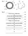
- FIG. 8shows a schematic flow diagram of a method for positioning an inner tube in an outer tube of an endoscope. Although this method is also applicable to positioning devices and endoscopes, differing from the above based on the FIGS. 1 to 7 are distinguished, reference numerals from the FIGS. 1 to 7 used to facilitate understanding.
- a first step 101an optical waveguide 28 is arranged on an inner tube 21.
- a positioning device 30is clamped to the inner tube 21.
- the one or more optical waveguides 28 arranged on the inner tube 21 in the first step 101are at least loosely fixed on the inner tube 21.
- the positioning device 30is attached to the inner tube 21 by gluing, soldering, welding or otherwise.
- optical waveguides 28are arranged on the inner tube 21.
- the optical waveguides 28can be arranged between the inner tube 21 and the positioning device 30 or the positioning device 30 between the inner tube 21 and the optical waveguides 28.
- a jacketis formed around the inner tube 21, the positioning device 30 and the optical waveguide or conductors 28.
- the sheath 40is formed, for example, by shrinking a shrink tubing or by wrapping or rewinding with one or more threads, wires, ribbons or filament or wire or ribbon-like devices.
- a sixth step 106the inner tube 21 is inserted into an outer tube 22.
- the positioning device 30can be inserted into the outer tube 22 and fixed there by clamping and optionally by gluing, soldering or welding before the inner tube 21 is inserted into the outer tube 22.
- one or more optical waveguides 28can be arranged between the inner surface 26 of the outer tube 22 and the positioning device 30 and at least loosely fixed.
Landscapes
- Health & Medical Sciences (AREA)
- Life Sciences & Earth Sciences (AREA)
- Physics & Mathematics (AREA)
- Surgery (AREA)
- Optics & Photonics (AREA)
- Engineering & Computer Science (AREA)
- Biomedical Technology (AREA)
- General Health & Medical Sciences (AREA)
- Pathology (AREA)
- Nuclear Medicine, Radiotherapy & Molecular Imaging (AREA)
- Biophysics (AREA)
- Heart & Thoracic Surgery (AREA)
- Medical Informatics (AREA)
- Molecular Biology (AREA)
- Animal Behavior & Ethology (AREA)
- Radiology & Medical Imaging (AREA)
- Public Health (AREA)
- Veterinary Medicine (AREA)
- Astronomy & Astrophysics (AREA)
- General Physics & Mathematics (AREA)
- Manufacturing & Machinery (AREA)
- Endoscopes (AREA)
- Instruments For Viewing The Inside Of Hollow Bodies (AREA)
Abstract
Description
Translated fromGermanDie vorliegende Erfindung bezieht sich auf eine Positionierungseinrichtung zur Positionierung eines Innenrohrs in einem Außenrohr eines Endoskops, ein Endoskop mit einer solchen Positionierungseinrichtung und ein Verfahren zum Positionieren eines Innenrohrs in einem Außenrohr eines Endoskops.The present invention relates to a positioning device for positioning an inner tube in an outer tube of an endoscope, an endoscope having such a positioning device, and a method for positioning an inner tube in an outer tube of an endoscope.
Der Schaft eines Endoskops weist oft mehrere ineinander angeordnete Rohre auf. In den Hohlräumen zwischen diesen Rohren sind beispielsweise Lichtwellenleiter zur Übertragung von Licht zur Beleuchtung eines zu untersuchenden Hohlraums angeordnet. Bei einem medizinischen Eingriff kann der Schaft eines starren Endoskops durch das medizinische Personal einer erheblichen mechanischen Belastung ausgesetzt werden, insbesondere einer Biegebelastung. Erhebliche mechanische Spannungen können auch während des Autoklavierens aufgrund unterschiedlicher thermischer Ausdehnungskoeffizienten verschiedener Bauteil oder aufgrund von Temperaturgradienten entstehen.The shaft of an endoscope often has several nested tubes. In the cavities between these tubes, for example, optical fibers for transmitting light to illuminate a cavity to be examined are arranged. In the case of a medical intervention, the shaft of a rigid endoscope can be subjected to considerable mechanical stress by the medical staff, in particular a bending load. Significant mechanical stresses can also arise during autoclaving due to different thermal expansion coefficients of different components or due to temperature gradients.
Ein mechanisches Verbiegen eines Rohrs aufgrund entsprechender mechanischer Belastung oder auch aufgrund thermischer Spannungen während des Autoklavierens verformt die Hohlräume zwischen den Rohren. In den Hohlräumen angeordnete Lichtwellenleiter, elektrische Leiter oder andere Funktionselemente können dadurch verschoben, gedehnt, gestaucht, gequetscht, zerrieben oder auf andere Weise beschädigt werden. Außerdem kann ein Verbiegen der Rohre und die resultierende Verschiebung von Lichtwellenleitern eine einseitige und ungleichmäßige Beleuchtung des Raums vor dem distalen Ende des Endoskops zur Folge habenMechanical bending of a pipe due to corresponding mechanical stress or due to thermal stresses during autoclaving deforms the voids between the pipes. Arranged in the cavities optical fiber, electrical conductors or other functional elements can be moved, stretched, compressed, crushed, crushed or damaged in any other way. In addition, bending the tubes and resulting displacement of optical fibers can result in unilateral and uneven illumination of the space in front of the distal end of the endoscope
Um eine Verformung von Hohlräumen zwischen ineinander angeordneten Rohren eines Schafts eines Endoskops zu vermeiden, werden herkömmlich im Wesentlichen in Längsrichtung des Schafts verlaufende Drahtstücke oder Flügelsegmente an das jeweils innere Rohr gelötet, geschweißt oder geklebt. Zwischen den Drahtstücken oder Flügelsegmenten können Lichtwellenleiter und andere Einrichtungen im Zwischenraum zwischen den Rohren angeordnet werden. Die Drahtstücke oder Flügelsegmente dienen der mechanischen Abstützung des jeweils inneren Rohres gegenüber dem jeweils äußeren Rohr. Dadurch wird eine Verformung des Zwischenraums vermindert und durch die Verteilung mechanischer Spannungen auf beide Rohre die Steifheit des Schafts erhöht.In order to avoid deformation of cavities between tubes of a stem of an endoscope, which are arranged inside one another, wire pieces or wing segments running essentially in the longitudinal direction of the stem are conventionally soldered, welded or glued to the respective inner tube. Between the pieces of wire or wing segments, optical fibers and other devices can be placed in the space between the tubes. The wire pieces or wing segments serve to mechanically support the respective inner tube relative to the respective outer tube. As a result, a deformation of the gap is reduced and increases the stiffness of the shaft by the distribution of mechanical stresses on both tubes.
Das Anordnen und Fügen der Drahtstücke oder Flügelsegmente am jeweils inneren Rohr ist jedoch zeitaufwendig und arbeits- und damit kostenintensiv. Ferner müssen die an das innere Rohr gefügten Flügelsegmente anschließend an die Innenkontur des Außenrohrs angepasst werden, beispielsweise durch Überdrehen. Dabei können die Drahtstücke oder Flügelsegmente wieder abgerissen werden.However, the arrangement and joining of the wire pieces or wing segments on the respective inner tube is time-consuming and labor-intensive and thus cost-intensive. Furthermore, the wing segments joined to the inner tube must then be adapted to the inner contour of the outer tube, for example by over-tightening. The wire pieces or wing segments can be torn off again.
Eine Aufgabe der vorliegenden Erfindung besteht darin, eine verbesserte Positionierungseinrichtung, ein verbessertes Endoskop und ein verbessertes Verfahren zum Positionieren eines Innenrohrs in einem Außenrohr eines Endoskops zu schaffen.An object of the present invention is to provide an improved positioning device, an improved endoscope and an improved method for positioning an inner tube in an outer tube of an endoscope.
Diese Aufgabe wird durch die Gegenstände der unabhängigen Ansprüche gelöst.This object is solved by the subject matters of the independent claims.
Weiterbildungen sind in den abhängigen Ansprüchen angegeben.Further developments are specified in the dependent claims.
Verschiedene Ausführungsformen der vorliegenden Erfindung beruhen auf der Idee, eine Positionierungseinrichtung zur zentrischen oder exzentrischen Positionierung eines Innenrohrs in einem Außenrohr eines Endoskops am Innenrohr oder am Außenrohr zu klemmen. An die Stelle der herkömmlichen stoffschlüssigen Verbindung tritt hier eine kraftschlüssige Verbindung. Dabei umgreift die Positionierungseinrichtung das Innenrohr insbesondere zu mehr als der Hälfte. Die Klemmung erfolgt aufgrund der Elastizität der Positionierungseinrichtung. Die gesamte Positionierungseinrichtung oder aufgrund ihrer Form besonders elastische Abschnitte derselben bilden eine Klemmeinrichtung. Die Positionierungseinrichtung ist also für eine Klemmung am Innenrohr oder im Außenrohr ausgebildet.Various embodiments of the present invention are based on the idea of clamping a positioning device for centric or eccentric positioning of an inner tube in an outer tube of an endoscope on the inner tube or on the outer tube. In place of the conventional cohesive connection occurs here a non-positive connection. In this case, the positioning device surrounds the inner tube in particular more than half. The clamping is due to the elasticity of the positioning device. The entire positioning device or due to their shape particularly elastic portions thereof form a clamping device. The positioning device is thus designed for clamping on the inner tube or in the outer tube.
Durch die Klemmung kann die Positionierungseinrichtung innerhalb kürzester Zeit montiert und danach sogar noch justiert werden. Die Geometrie der Positionierungseinrichtung ist bei ihrer Herstellung genau einstellbar. Anders als beim Schweißen, Löten oder Kleben bleibt bei der hier vorgesehenen bloßen Klemmung die Geometrie der Positionierungseinrichtung erhalten. Insbesondere ist die Lage der Außenkontur der Positionierungseinrichtung nach der Klemmung präzise definiert, da die Positionierungseinrichtung nicht teilweise aufgeschmolzen wird und auch kein Lot oder Klebstoff zwischen die Positionierungseinrichtung und das Innenrohr gelangen kann. Ein Überdrehen wie bei herkömmlich an das Innenrohr gefügten Drahtstücken oder Flügelsegmenten ist nicht erforderlich. Insgesamt resultiert ein deutlich verminderter Aufwand bei der Positionierung eines Innenrohrs in einem Außenrohr mittels der hier beschriebenen Positionierungseinrichtung. Ferner kann die Positionierungseinrichtung anders als beim Stand der Technik auch zunächst im Außenrohr geklemmt werden bevor das Innenrohr in das Außenrohr eingeführt wird.By clamping the positioning device can be mounted within a very short time and then even adjusted. The geometry of the positioning device is precisely adjustable during its manufacture. Unlike welding, soldering or gluing, the geometry of the positioning device is maintained in the case of mere clamping provided here. In particular, the position of the outer contour of the positioning device after clamping is precisely defined, since the positioning device is not partially melted and also no solder or adhesive can get between the positioning device and the inner tube. Overturning as with conventionally attached to the inner tube wire pieces or wing segments is not required. Overall, a significantly reduced effort results in the positioning of an inner tube in an outer tube by means of the positioning device described here. Furthermore, unlike the prior art, the positioning device can also be first clamped in the outer tube before the inner tube is inserted into the outer tube.
Eine Positionierungseinrichtung zur Positionierung eines Innenrohrs in einem Außenrohr eines Endoskops umfasst zumindest eine Innenstützfläche zur Abstützung der Positionierungseinrichtung am Innenrohr, zumindest eine Außenstützfläche zur Abstützung der Positionierungseinrichtung am Außenrohr und eine Klemmeinrichtung zur Klemmung der Positionierungseinrichtung am Innenrohr oder am Außenrohr.A positioning device for positioning an inner tube in an outer tube of an endoscope comprises at least one inner support surface for supporting the positioning device on the inner tube, at least one outer support surface for supporting the positioning device on the outer tube and a clamping device for clamping the positioning device on the inner tube or on the outer tube.
Die Positionierungseinrichtung ist insbesondere ausgebildet, um das Innenrohr zu mehr als der Hälfte zu umgreifen. Die Positionierungseinrichtung kann mehrere voneinander beabstandete Innenstützflächen und/oder mehrere voneinander beabstandete Außenstützflächen aufweisen. Eine oder mehrere Innenstützflächen und eine bzw. mehrere Außenstützflächen können einander jeweils in radialer Richtung gegenüberliegen. Alternativ sind zumindest eine Innenstützfläche und zumindest eine Außenstützfläche in umfänglicher Richtung abwechselnd bzw. alternierend angeordnet, wobei Innenstützflächen und Außenstützflächen einander in umfänglicher Richtung nur wenig oder gar nicht überlappen. In diesem und anderen Fällen können einer oder mehrere Stege in radialer Richtung jeweils eine Innenstützfläche und eine Außenstützfläche verbinden. Eine Positionierungseinrichtung weist insbesondere mindestens drei derartige Stege als eigentliche Stützabschnitte zwischen Innenrohr und Außenrohr auf, wobei der Abstand zwischen benachbarten Stegen insbesondere weniger als 180° und vorteilhaft jeweils ca. 120° oder weniger beträgt.The positioning device is in particular designed to encompass the inner tube more than half. The positioning device may have a plurality of spaced apart inner support surfaces and / or a plurality of spaced apart outer support surfaces. One or more inner support surfaces and one or more outer support surfaces may each face each other in the radial direction. Alternatively, at least one inner support surface and at least one outer support surface are arranged alternately or alternately in the circumferential direction, wherein inner support surfaces and outer support surfaces overlap each other in the circumferential direction only slightly or not at all. In this and other cases, one or more webs in the radial direction in each case connect an inner support surface and an outer support surface. In particular, a positioning device has at least three such webs as actual support sections between inner tube and outer tube, wherein the distance between adjacent webs is in particular less than 180 ° and advantageously approximately 120 ° or less.
Wenn die Positionierungseinrichtung nur eine Innenstützfläche oder nur eine Außenstützfläche aufweist, erstreckt sich diese in umfänglicher Richtung insbesondere über mehr als 180°. Wenn die Positionierungseinrichtung mehrere Innenstützflächen aufweist, ist der Abstand zwischen einander gegenüberliegenden Rändern von nächst benachbarten Innenstützflächen insbesondere kleiner als 180° oder kleiner als 120°, ggf. bezogen auf eine Symmetrieachse des Innenrohrs. Wenn die Positionierungseinrichtung mehrere Außenstützflächen aufweist, ist der Abstand zwischen einander gegenüberliegenden Rändern nächst benachbarter Außenstützflächen insbesondere kleiner als 180° oder kleiner als 120°, ggf. bezogen auf eine Symmetrieachse des Außenrohrs.If the positioning device has only one inner support surface or only one outer support surface, this extends in the circumferential direction in particular over more than 180 °. If the positioning device has a plurality of inner support surfaces, the distance between opposing edges of nearest adjacent inner support surfaces is in particular less than 180 ° or smaller than 120 °, possibly with respect to an axis of symmetry of the inner tube. If the positioning device has a plurality of outer support surfaces, the distance between opposite edges of adjacent adjacent outer support surfaces is in particular less than 180 ° or less than 120 °, possibly with respect to an axis of symmetry of the outer tube.
Ein Endoskop umfasst eine oder mehrere der oben beschriebenen Positionierungseinrichtungen. Auf das Innenrohr und die Positionierungseinrichtung kann ein Schrumpfschlauch aufgeschrumpft sein. Das Innenrohr und die Positionierungseinrichtung können umwickelt oder umsponnen sein, insbesondere mittels eines oder mehrerer Fäden, Drähte, Bänder oder faden- oder draht- oder bandartiger Einrichtungen.An endoscope includes one or more of the positioning devices described above. On the inner tube and the positioning device, a shrink tube can be shrunk. The inner tube and the positioning device can be wrapped or wound, in particular by means of one or more threads, wires, bands or thread or wire or ribbon-like devices.
Bei einem Verfahren zum Positionieren eines Innenrohrs in einem Außenrohr eines Endoskops wird zunächst eine Positionierungseinrichtung am Innenrohr oder im Außenrohr geklemmt, wobei die Positionierungseinrichtung eine Innenstützfläche zur Abstützung am Innenrohr und eine Außenstützfläche zur Abstützung am Außenrohr aufweist. Nach dem Klemmen der Positionierungseinrichtung wird das Innenrohr im Außenrohr angeordnet. Bei einem weiteren Schritt vor oder nach dem Klemmen der Positionierungseinrichtung kann ein Lichtwellenleiter an der Außenwand des Innenrohrs oder an der Innenwand des Außenrohrs angeordnet werden. Die Positionierungseinrichtung kann ferner beim Klemmen oder nach dem Klemmen stoffschlüssig mit dem Innenrohr oder dem Außenrohr verbunden werden, beispielsweise durch Kleben oder Löten. Nach dem Klemmen der Positionierungseinrichtung am Innenrohr, insbesondere ggf. vor oder nach dem Anordnen eines Lichtwellenleiters an der Außenwand des Innenrohrs, kann ein Schrumpfschlauch auf das Innenrohr und die Positionierungseinrichtung aufgeschrumpft werden. Alternativ oder zusätzlich werden das Innenrohr und die Positionierungseinrichtung umwickelt oder umsponnen, beispielsweise mittels eines oder mehrerer Fäden, Drähte, Bänder oder faden- oder draht- oder bandartiger Einrichtungen.In a method for positioning an inner tube in an outer tube of an endoscope, a positioning device is first clamped on the inner tube or in the outer tube, wherein the positioning device has an inner support surface for support on the inner tube and an outer support surface for support on the outer tube. After clamping the positioning device, the inner tube is arranged in the outer tube. In a further step before or after the clamping of the positioning device, an optical waveguide can be arranged on the outer wall of the inner tube or on the inner wall of the outer tube. The positioning device can also be connected to the inner tube or the outer tube cohesively when clamping or after clamping, for example by gluing or soldering. After clamping the positioning device on the inner tube, in particular if necessary before or after arranging an optical waveguide on the outer wall of the inner tube, a shrink tube can be shrunk onto the inner tube and the positioning device. Alternatively or additionally, the inner tube and the positioning device are wrapped or wound, for example by means of one or more threads, wires, bands or filament or wire or ribbon-like devices.
Die vorliegende Erfindung ist insbesondere bei einem Innenrohr und einem Außenrohr mit jeweils kreisförmigem Querschnitt anwendbar, ist jedoch auch bei Rohren mit elliptischem, rechteckigem oder anderem Querschnitt anwendbar. Als Innenrohr wird hier das Rohr mit dem kleineren Querschnitt, als Außenrohr das Rohr mit dem größeren Querschnitt bezeichnet. Darüber hinaus kann das Endoskop ein oder mehrere Rohre innerhalb des Innenrohrs und/oder ein Rohr, in dem das Außenrohr angeordnet ist, aufweisen.The present invention is particularly applicable to an inner tube and an outer tube each having a circular cross section, but is also applicable to tubes having an elliptical, rectangular or other cross section. The inner tube here is the tube with the smaller cross section, the outer tube is the tube with the larger cross section. In addition, the endoscope can have one or more tubes inside the inner tube and / or a tube in which the outer tube is arranged.
Nachfolgend werden Ausführungsformen anhand der beigefügten Figuren näher erläutert. Es zeigen:
- Figur 1
- eine schematische Darstellung eines Endoskops;
- Figur 2
- eine schematische Darstellung eines Querschnitts und eines Längsschnitts eines Schafts eines Endoskops;
- Figur 3
- eine schematische Darstellung eines Querschnitts und eines Längsschnitts eines Schafts eines Endoskops;
- Figur 4
- eine schematische Darstellung von Querschnitten eines Schafts eines Endo- skops und einer Positionierungseinrichtung;
- Figur 5
- eine schematische Darstellung von Querschnitten eines Schafts eines Endo- skops und einer Positionierungseinrichtung;
- Figur 6
- eine schematische Darstellung von Querschnitten eines Schafts eines Endo- skops und einer Positionierungseinrichtung;
- Figur 7
- eine schematische Darstellung von Querschnitten eines Schafts eines Endo- skops und einer Positionierungseinrichtung;
- Figur 8
- ein schematisches Flussdiagramm.
- FIG. 1
- a schematic representation of an endoscope;
- FIG. 2
- a schematic representation of a cross section and a longitudinal section of a shaft of an endoscope;
- FIG. 3
- a schematic representation of a cross section and a longitudinal section of a shaft of an endoscope;
- FIG. 4
- a schematic representation of cross sections of a shaft of an endoscope and a positioning device;
- FIG. 5
- a schematic representation of cross sections of a shaft of an endoscope and a positioning device;
- FIG. 6
- a schematic representation of cross sections of a shaft of an endoscope and a positioning device;
- FIG. 7
- a schematic representation of cross sections of a shaft of an endoscope and a positioning device;
- FIG. 8
- a schematic flow diagram.
Die nachfolgend beschriebenen
In einem Zwischenraum 24 zwischen einer äußeren Oberfläche 25 des Innenrohrs 21 und einer inneren Oberfläche 26 des Außenrohrs 22 sind Lichtwellenleiter 28 und eine Positionierungseinrichtung 30 angeordnet. In den Querschnitten A-A ist erkennbar, dass die Positionierungseinrichtung 30 das Innenrohr jeweils zu mehr als der Hälfte umgreift. Eine Innenstützfläche 31 der Positionierungseinrichtung 30 liegt in einem zusammenhängenden Bereich an der äußeren Oberfläche 25 des Innenrohrs 21 an, der mehr als die Hälfte des äußeren Umfangs des Querschnitts des Innenrohrs 21 umfasst. Eine Außenstützfläche 32 der Positionierungseinrichtung 30 liegt in einem zusammenhängenden Bereich an der inneren Oberfläche 26 des Außenrohrs 22 an, der mehr als die Hälfte des inneren Umfangs des Querschnitts des Außenrohrs 22 umfasst. Der im dargestellten Querschnitt A-A nicht von der Positionierungseinrichtung 30 eingenommene Bereich des Zwischenraums zwischen dem Innenrohr 21 und dem Außenrohr 22 wird von in Längsrichtung des Schafts 11 verlaufenden Lichtwellenleitern 28 eingenommen.In a
Im Längsschnitt B-B ist jeweils erkennbar, dass die in Längsrichtung des Schafts 11 gemessene Länge der Positionierungseinrichtung 30 jeweils kleiner ist als der Außendurchmesser des Innenrohrs 21. Die Positionierungseinrichtung 30 kann jedoch von den Darstellungen in den
Bei der in
Bei der in
Die oben anhand der
Die
Bei den in den
Die in
Die Innenstützfläche 31 ist größer oder wesentlich größer als die drei Außenstützflächen 32 zusammen. Deshalb ist die Haftreibung zwischen der Innenstützfläche 31 und der äußeren Oberfläche 25 des Innenrohrs 21 größer oder wesentlich größer als die Haftreibung zwischen den Außenstützflächen 32 und der inneren Oberfläche 26 des Außenrohrs 22. Dies kann durch eine entsprechende Vorspannung der Positionierungseinrichtung 30 bzw. der Klemmeinrichtung 33 begünstigt werden. Dadurch eignet sich die in
Die in
Die Außenstützfläche 32 ist größer oder wesentlich größer als die drei Innenstützflächen 31 zusammen. Deshalb ist die Haftreibung zwischen der Außenstützfläche 32 und der inneren Oberfläche 26 des Außenrohrs 22 größer oder wesentlich größer als die Haftreibung zwischen den Innenstützflächen 31 und der äußeren Oberfläche 25 des Innenrohrs 21. Dies kann durch eine entsprechende Vorspannung der Positionierungseinrichtung 30 bzw. der Klemmeinrichtung 33 begünstigt werden. Dadurch eignet sich die in
Die in
Ähnlich wie bei der oben anhand der
Die Darstellung in
Es ist erkennbar, dass die oben anhand der
Positionierungseinrichtungen 30, wie sie oben anhand der
Eine Positionierungseinrichtung 30, wie sie oben anhand der
Bei allen oben dargestellten Ausführungsformen hat der Schaft 11 des Endoskops 10 einen kreisförmigen Querschnitt. Die oben beschriebenen Positionierungseinrichtungen sind jedoch auch für ein Endoskop mit einem Schaft und mit Innen- und/oder Außenrohren geeignet, die nicht kreiszylindrisch sind.In all embodiments shown above, the
Bei einem ersten Schritt 101 wird ein Lichtwellenleiter 28 an einem Innenrohr 21 angeordnet. Bei einem zweiten Schritt 102 wird eine Positionierungseinrichtung 30 an das Innenrohr 21 geklemmt. Dabei werden der oder die beim ersten Schritt 101 am Innenrohr 21 angeordneten Lichtwellenleiter 28 am Innenrohr 21 zumindest lose fixiert.In a
Bei einem optionalen dritten Schritt 103 wird die Positionierungseinrichtung 30 durch Kleben, Löten, Schweißen oder auf andere Weise an dem Innenrohr 21 befestigt.In an optional
Alternativ zum ersten Schritt 101 oder zusätzlich zu diesem, werden bei einem vierten Schritt 104 nach dem dritten Schritt 103 Lichtwellenleiter 28 am Innenrohr 21 angeordnet. Dabei können die Lichtwellenleiter 28 zwischen dem Innenrohr 21 und der Positionierungseinrichtung 30 oder die Positionierungseinrichtung 30 zwischen dem Innenrohr 21 und den Lichtwellenleitern 28 angeordnet sein.As an alternative to the
Bei einem optionalen fünften Schritt 105 wird ein Mantel um das Innenrohr 21, die Positionierungseinrichtung 30 und den oder die Lichtwellenleiter 28 gebildet. Der Mantel 40 wird beispielsweise durch Aufschrumpfen eines Schrumpfschlauchs oder durch Umwickeln oder Umspinnen mit einem oder mehreren Fäden, Drähten, Bändern oder faden- oder draht- oder bandartigen Einrichtungen gebildet.In an optional
Bei einem sechsten Schritt 106 wird das Innenrohr 21 in ein Außenrohr 22 eingesetzt.In a
Alternativ zum Klemmen der Positionierungseinrichtung 30 am Innenrohr 21 kann beim zweiten Schritt 102 die Positionierungseinrichtung 30 in das Außenrohr 22 eingesetzt und dort durch Klemmen und optional durch Kleben, Löten oder Schweißen fixiert werden bevor das Innenrohr 21 in das Außenrohr 22 eingesetzt wird. Vor oder beim Klemmen der Positionierungseinrichtung 30 im Außenrohr 22 können eine oder mehrere Lichtwellenleiter 28 zwischen der inneren Oberfläche 26 des Außenrohrs 22 und der Positionierungseinrichtung 30 angeordnet und zumindest lose fixiert werden.As an alternative to clamping the
- 1010
- Endoskopendoscope
- 1111
- Schaft des Endoskops 10Shaft of the
endoscope 10 - 1212
- distales Ende des Endoskops 10distal end of the
endoscope 10 - 1313
- proximales Ende des Endoskops 10proximal end of the
endoscope 10 - 1414
- Okular des Endoskops 10Eyepiece of the
endoscope 10 - 1515
- Kupplung für LichtquelleClutch for light source
- 2121
- Innenrohr des Schafts 11Inner tube of the
shaft 11 - 2222
- Außenrohr des Schafts 11Outer tube of the
shaft 11 - 2323
- Lumen des Innenrohrs 21Lumen of the
inner tube 21 - 2424
- Zwischenraum zwischen Innenrohr 21 und Außenrohr 22Interspace between
inner tube 21 and outer tube 22nd - 2525
- äußere Oberfläche des Innenrohrs 21outer surface of the
inner tube 21 - 2626
- innere Oberfläche des Außenrohrs 22Inner surface of the outer tube 22nd
- 2828
- Lichtwellenleiteroptical fiber
- 3030
- Positionierungseinrichtungpositioning device
- 3131
- Innenstützfläche der Positionierungseinrichtung 30Inner support surface of the
positioning device 30 - 3232
- Außenstützfläche der Positionierungseinrichtung 30External support surface of the
positioning device 30 - 3333
- Klemmeinrichtung der Positionierungseinrichtung 30Clamping device of the
positioning device 30 - 3434
- Stegweb
- 4040
- Mantelcoat
- 101101
- erster Schrittfirst step
- 102102
- zweiter Schrittsecond step
- 103103
- dritter SchrittThird step
- 104104
- vierter Schrittfourth step
- 105105
- fünfter Schrittfifth step
- 106106
- sechster Schrittsixth step
Claims (14)
Translated fromGermanausgebildet ist, um das Innenrohr (21) zu mehr als der Hälfte zu umgreifen, und zumindest eineInnenstützfläche (31) und zumindest eineAußenstützfläche (32) in umfänglicher Richtungabwechselnd angeordnet sind.Positioning device (30) according to the preceding claim, wherein the positioning device (30)
is formed to engage around the inner tube (21) more than half, and at least oneinner support surface (31) and at least oneouter support surface (32)are arrangedalternately in the circumferential direction.
Applications Claiming Priority (1)
| Application Number | Priority Date | Filing Date | Title |
|---|---|---|---|
| DE102009037317ADE102009037317A1 (en) | 2009-08-14 | 2009-08-14 | Device and method for centering the inner and outer tubes of an endoscope |
Publications (2)
| Publication Number | Publication Date |
|---|---|
| EP2283768A1true EP2283768A1 (en) | 2011-02-16 |
| EP2283768B1 EP2283768B1 (en) | 2016-10-05 |
Family
ID=43255479
Family Applications (1)
| Application Number | Title | Priority Date | Filing Date |
|---|---|---|---|
| EP10008133.0ARevokedEP2283768B1 (en) | 2009-08-14 | 2010-08-04 | Device and method for centring the internal and external tube of an endoscope |
Country Status (3)
| Country | Link |
|---|---|
| US (1) | US10244930B2 (en) |
| EP (1) | EP2283768B1 (en) |
| DE (1) | DE102009037317A1 (en) |
Cited By (2)
| Publication number | Priority date | Publication date | Assignee | Title |
|---|---|---|---|---|
| EP2770361A1 (en)* | 2013-02-20 | 2014-08-27 | Karl Storz GmbH & Co. KG | Optical tube for an endoscope, endoscope and method for mounting at least one rod lens in an optical tube |
| US20220280030A1 (en)* | 2021-03-04 | 2022-09-08 | Olympus Winter & Ibe Gmbh | Endoscope |
Families Citing this family (2)
| Publication number | Priority date | Publication date | Assignee | Title |
|---|---|---|---|---|
| CN102798928A (en)* | 2011-05-27 | 2012-11-28 | 吕路可 | Light-transmissible composite plastic tube body |
| DE102020105469A1 (en)* | 2020-03-02 | 2021-09-02 | Karl Storz Se & Co. Kg | Endoscope with a light guide device, method for producing an endoscope with a light guide device and use of a method for producing an endoscope |
Citations (5)
| Publication number | Priority date | Publication date | Assignee | Title |
|---|---|---|---|---|
| US4569335A (en)* | 1983-04-12 | 1986-02-11 | Sumitomo Electric Industries, Ltd. | Fiberscope |
| EP0416371A2 (en)* | 1989-09-04 | 1991-03-13 | Richard Wolf GmbH | Optic for endoscope |
| US5651759A (en)* | 1994-03-24 | 1997-07-29 | United States Surgical Corporation | Method of making arthroscope having a shim for angularly orienting illumination fibers |
| JP2001017381A (en)* | 1999-07-05 | 2001-01-23 | Olympus Optical Co Ltd | Endoscope |
| DE10307903A1 (en)* | 2003-02-18 | 2004-09-02 | Karl Storz Gmbh & Co. Kg | Method for mounting an endoscope |
Family Cites Families (20)
| Publication number | Priority date | Publication date | Assignee | Title |
|---|---|---|---|---|
| US3860353A (en)* | 1972-07-05 | 1975-01-14 | Ford Motor Co | Adjustable connection |
| US4286894A (en) | 1979-03-21 | 1981-09-01 | Roller Bearing Company Of America | Tolerance rings |
| US4981390A (en)* | 1987-03-06 | 1991-01-01 | The Ray Engineering Co., Ltd. | Tolerance ring with retaining means |
| US4819630A (en)* | 1987-03-20 | 1989-04-11 | Laser Photonics, Inc. | Flexible light transmissive apparatus and method |
| JPH03128028A (en)* | 1989-10-13 | 1991-05-31 | Machida Seisakusho:Kk | Angle for curving operation device |
| JP2852785B2 (en)* | 1990-03-14 | 1999-02-03 | 株式会社町田製作所 | Angle for flexible tube |
| US5281212A (en) | 1992-02-18 | 1994-01-25 | Angeion Corporation | Laser catheter with monitor and dissolvable tip |
| US5300069A (en) | 1992-08-12 | 1994-04-05 | Daniel Hunsberger | Electrosurgical apparatus for laparoscopic procedures and method of use |
| DE19500353C2 (en)* | 1995-01-07 | 1997-06-26 | Foth Hans Jochen Dr | Laser surgical device |
| US6997931B2 (en)* | 2001-02-02 | 2006-02-14 | Lsi Solutions, Inc. | System for endoscopic suturing |
| JP4594612B2 (en)* | 2003-11-27 | 2010-12-08 | オリンパス株式会社 | Insertion aid |
| US20060041186A1 (en) | 2004-08-17 | 2006-02-23 | Vancaillie Thierry G | Continuous flow single sheath for endoscope |
| JP4472549B2 (en)* | 2005-02-14 | 2010-06-02 | オリンパスメディカルシステムズ株式会社 | Endoscope device |
| US8052597B2 (en)* | 2005-08-30 | 2011-11-08 | Boston Scientific Scimed, Inc. | Method for forming an endoscope articulation joint |
| US20090137875A1 (en)* | 2005-09-22 | 2009-05-28 | Hideya Kitagawa | Endoscope insertion portion |
| DE102005051209A1 (en) | 2005-10-18 | 2007-04-19 | Karl Storz Gmbh & Co. Kg | Endoscope consists of a shaft with outer and inner pipe that house a shorter intermediate pipe and has channel to hold fibre optic |
| US7503893B2 (en)* | 2006-02-03 | 2009-03-17 | Cannuflow, Inc. | Anti-extravasation sheath and method |
| US7615004B2 (en)* | 2006-03-30 | 2009-11-10 | Ethicon Endo-Surgery, Inc. | Endoscopic ancillary attachment devices |
| US20070270647A1 (en) | 2006-05-19 | 2007-11-22 | Ams Research Corporation | Handle for Multifunction Endoscope |
| US20080277853A1 (en)* | 2007-05-09 | 2008-11-13 | Microline Pentax Inc. | Clip for coupling a surgical tool and scope |
- 2009
- 2009-08-14DEDE102009037317Apatent/DE102009037317A1/ennot_activeWithdrawn
- 2010
- 2010-08-04EPEP10008133.0Apatent/EP2283768B1/ennot_activeRevoked
- 2010-08-13USUS12/856,337patent/US10244930B2/enactiveActive
Patent Citations (5)
| Publication number | Priority date | Publication date | Assignee | Title |
|---|---|---|---|---|
| US4569335A (en)* | 1983-04-12 | 1986-02-11 | Sumitomo Electric Industries, Ltd. | Fiberscope |
| EP0416371A2 (en)* | 1989-09-04 | 1991-03-13 | Richard Wolf GmbH | Optic for endoscope |
| US5651759A (en)* | 1994-03-24 | 1997-07-29 | United States Surgical Corporation | Method of making arthroscope having a shim for angularly orienting illumination fibers |
| JP2001017381A (en)* | 1999-07-05 | 2001-01-23 | Olympus Optical Co Ltd | Endoscope |
| DE10307903A1 (en)* | 2003-02-18 | 2004-09-02 | Karl Storz Gmbh & Co. Kg | Method for mounting an endoscope |
Cited By (4)
| Publication number | Priority date | Publication date | Assignee | Title |
|---|---|---|---|---|
| EP2770361A1 (en)* | 2013-02-20 | 2014-08-27 | Karl Storz GmbH & Co. KG | Optical tube for an endoscope, endoscope and method for mounting at least one rod lens in an optical tube |
| US9661988B2 (en) | 2013-02-20 | 2017-05-30 | Karl Storz Gmbh & Co. Kg | Optics tube for an endoscope, endoscope, and method for mounting at least one rod lens in an optics tube |
| US20220280030A1 (en)* | 2021-03-04 | 2022-09-08 | Olympus Winter & Ibe Gmbh | Endoscope |
| US11963664B2 (en)* | 2021-03-04 | 2024-04-23 | Olympus Winter & Ibe Gmbh | Endoscope having support body with segmented annular space |
Also Published As
| Publication number | Publication date |
|---|---|
| DE102009037317A1 (en) | 2011-02-17 |
| US20110040151A1 (en) | 2011-02-17 |
| EP2283768B1 (en) | 2016-10-05 |
| US10244930B2 (en) | 2019-04-02 |
Similar Documents
| Publication | Publication Date | Title |
|---|---|---|
| EP1596703B1 (en) | Method for assembling an endoscope | |
| DE69506705T2 (en) | FIBER OPTICAL CABLE WITH EXTENDED CONTRACTION AREA, METHOD AND DEVICE FOR PRODUCING THE CABLE | |
| DE69022568T2 (en) | Fiber optic 1xN coupler and manufacturing process. | |
| DE69526400T2 (en) | Electrical isolator with optical fibers and associated manufacturing process | |
| DE3633021A1 (en) | ENDOSCOPE | |
| DE102011007878A1 (en) | Optical fiber device for an endoscope | |
| DE2626907A1 (en) | COUPLING FOR OPTICAL FIBERS | |
| DE19732991A1 (en) | Endoscope with fixation for components of the optical system and method for mounting the components | |
| DE3929285C3 (en) | Endoscope optics | |
| DE2949174C2 (en) | ||
| EP2283768B1 (en) | Device and method for centring the internal and external tube of an endoscope | |
| DE69313955T2 (en) | Connection device for fiber optic subsea cables | |
| DE1775881A1 (en) | Flexible hose | |
| DE4419691C1 (en) | Straight FRP bar for longitudinal load transmission | |
| EP2617348A1 (en) | Light guide with a bundle of optical fibres and a method for bending the light guide | |
| EP2853187B1 (en) | Manufacture of an endoscope with a light conducting device | |
| EP3107156B1 (en) | Removal device for a cable, method for removing a cable using the removal device and cable for use in the method | |
| EP0228506A2 (en) | Light guide, especially for medical instruments | |
| DE4410444A1 (en) | FO connector | |
| DE2534756C2 (en) | Heat shrinkable connector for two single fiber optic cables | |
| DE2723440A1 (en) | PLUG CONNECTION FOR FIBER WAVE GUIDE WITH AXIAL AND RADIAL TENSION OF A THREAD | |
| DE2650022A1 (en) | FIBER OPTICAL FIBER WITH PRECISE AREAS, PROCESS FOR THEIR PRODUCTION AND DEVICE FOR CARRYING OUT THE PROCESS | |
| DE4341481C2 (en) | Branching device | |
| DE2902576A1 (en) | Optic fibre protection system - freely supports fibre inside space centre of bundle of protective cables | |
| EP1872706B1 (en) | Method for manufacturing an endoscope and endoscope |
Legal Events
| Date | Code | Title | Description |
|---|---|---|---|
| PUAI | Public reference made under article 153(3) epc to a published international application that has entered the european phase | Free format text:ORIGINAL CODE: 0009012 | |
| AK | Designated contracting states | Kind code of ref document:A1 Designated state(s):AL AT BE BG CH CY CZ DE DK EE ES FI FR GB GR HR HU IE IS IT LI LT LU LV MC MK MT NL NO PL PT RO SE SI SK SM TR | |
| AX | Request for extension of the european patent | Extension state:BA ME RS | |
| 17P | Request for examination filed | Effective date:20110811 | |
| 17Q | First examination report despatched | Effective date:20140212 | |
| GRAP | Despatch of communication of intention to grant a patent | Free format text:ORIGINAL CODE: EPIDOSNIGR1 | |
| INTG | Intention to grant announced | Effective date:20160513 | |
| GRAS | Grant fee paid | Free format text:ORIGINAL CODE: EPIDOSNIGR3 | |
| GRAA | (expected) grant | Free format text:ORIGINAL CODE: 0009210 | |
| AK | Designated contracting states | Kind code of ref document:B1 Designated state(s):AL AT BE BG CH CY CZ DE DK EE ES FI FR GB GR HR HU IE IS IT LI LT LU LV MC MK MT NL NO PL PT RO SE SI SK SM TR | |
| REG | Reference to a national code | Ref country code:GB Ref legal event code:FG4D Free format text:NOT ENGLISH | |
| REG | Reference to a national code | Ref country code:CH Ref legal event code:EP | |
| REG | Reference to a national code | Ref country code:AT Ref legal event code:REF Ref document number:833856 Country of ref document:AT Kind code of ref document:T Effective date:20161015 | |
| REG | Reference to a national code | Ref country code:IE Ref legal event code:FG4D Free format text:LANGUAGE OF EP DOCUMENT: GERMAN | |
| REG | Reference to a national code | Ref country code:DE Ref legal event code:R096 Ref document number:502010012496 Country of ref document:DE | |
| REG | Reference to a national code | Ref country code:NL Ref legal event code:MP Effective date:20161005 | |
| REG | Reference to a national code | Ref country code:LT Ref legal event code:MG4D | |
| PG25 | Lapsed in a contracting state [announced via postgrant information from national office to epo] | Ref country code:LV Free format text:LAPSE BECAUSE OF FAILURE TO SUBMIT A TRANSLATION OF THE DESCRIPTION OR TO PAY THE FEE WITHIN THE PRESCRIBED TIME-LIMIT Effective date:20161005 | |
| PG25 | Lapsed in a contracting state [announced via postgrant information from national office to epo] | Ref country code:GR Free format text:LAPSE BECAUSE OF FAILURE TO SUBMIT A TRANSLATION OF THE DESCRIPTION OR TO PAY THE FEE WITHIN THE PRESCRIBED TIME-LIMIT Effective date:20170106 Ref country code:NO Free format text:LAPSE BECAUSE OF FAILURE TO SUBMIT A TRANSLATION OF THE DESCRIPTION OR TO PAY THE FEE WITHIN THE PRESCRIBED TIME-LIMIT Effective date:20170105 Ref country code:SE Free format text:LAPSE BECAUSE OF FAILURE TO SUBMIT A TRANSLATION OF THE DESCRIPTION OR TO PAY THE FEE WITHIN THE PRESCRIBED TIME-LIMIT Effective date:20161005 Ref country code:LT Free format text:LAPSE BECAUSE OF FAILURE TO SUBMIT A TRANSLATION OF THE DESCRIPTION OR TO PAY THE FEE WITHIN THE PRESCRIBED TIME-LIMIT Effective date:20161005 | |
| PG25 | Lapsed in a contracting state [announced via postgrant information from national office to epo] | Ref country code:IS Free format text:LAPSE BECAUSE OF FAILURE TO SUBMIT A TRANSLATION OF THE DESCRIPTION OR TO PAY THE FEE WITHIN THE PRESCRIBED TIME-LIMIT Effective date:20170205 Ref country code:FI Free format text:LAPSE BECAUSE OF FAILURE TO SUBMIT A TRANSLATION OF THE DESCRIPTION OR TO PAY THE FEE WITHIN THE PRESCRIBED TIME-LIMIT Effective date:20161005 Ref country code:ES Free format text:LAPSE BECAUSE OF FAILURE TO SUBMIT A TRANSLATION OF THE DESCRIPTION OR TO PAY THE FEE WITHIN THE PRESCRIBED TIME-LIMIT Effective date:20161005 Ref country code:PL Free format text:LAPSE BECAUSE OF FAILURE TO SUBMIT A TRANSLATION OF THE DESCRIPTION OR TO PAY THE FEE WITHIN THE PRESCRIBED TIME-LIMIT Effective date:20161005 Ref country code:HR Free format text:LAPSE BECAUSE OF FAILURE TO SUBMIT A TRANSLATION OF THE DESCRIPTION OR TO PAY THE FEE WITHIN THE PRESCRIBED TIME-LIMIT Effective date:20161005 Ref country code:PT Free format text:LAPSE BECAUSE OF FAILURE TO SUBMIT A TRANSLATION OF THE DESCRIPTION OR TO PAY THE FEE WITHIN THE PRESCRIBED TIME-LIMIT Effective date:20170206 Ref country code:NL Free format text:LAPSE BECAUSE OF FAILURE TO SUBMIT A TRANSLATION OF THE DESCRIPTION OR TO PAY THE FEE WITHIN THE PRESCRIBED TIME-LIMIT Effective date:20161005 | |
| REG | Reference to a national code | Ref country code:DE Ref legal event code:R026 Ref document number:502010012496 Country of ref document:DE | |
| PLBI | Opposition filed | Free format text:ORIGINAL CODE: 0009260 | |
| REG | Reference to a national code | Ref country code:FR Ref legal event code:PLFP Year of fee payment:8 | |
| PG25 | Lapsed in a contracting state [announced via postgrant information from national office to epo] | Ref country code:DK Free format text:LAPSE BECAUSE OF FAILURE TO SUBMIT A TRANSLATION OF THE DESCRIPTION OR TO PAY THE FEE WITHIN THE PRESCRIBED TIME-LIMIT Effective date:20161005 Ref country code:RO Free format text:LAPSE BECAUSE OF FAILURE TO SUBMIT A TRANSLATION OF THE DESCRIPTION OR TO PAY THE FEE WITHIN THE PRESCRIBED TIME-LIMIT Effective date:20161005 Ref country code:SK Free format text:LAPSE BECAUSE OF FAILURE TO SUBMIT A TRANSLATION OF THE DESCRIPTION OR TO PAY THE FEE WITHIN THE PRESCRIBED TIME-LIMIT Effective date:20161005 Ref country code:EE Free format text:LAPSE BECAUSE OF FAILURE TO SUBMIT A TRANSLATION OF THE DESCRIPTION OR TO PAY THE FEE WITHIN THE PRESCRIBED TIME-LIMIT Effective date:20161005 Ref country code:CZ Free format text:LAPSE BECAUSE OF FAILURE TO SUBMIT A TRANSLATION OF THE DESCRIPTION OR TO PAY THE FEE WITHIN THE PRESCRIBED TIME-LIMIT Effective date:20161005 | |
| 26 | Opposition filed | Opponent name:HENKE-SASS, WOLF GMBH Effective date:20170705 | |
| PLAX | Notice of opposition and request to file observation + time limit sent | Free format text:ORIGINAL CODE: EPIDOSNOBS2 | |
| PG25 | Lapsed in a contracting state [announced via postgrant information from national office to epo] | Ref country code:SM Free format text:LAPSE BECAUSE OF FAILURE TO SUBMIT A TRANSLATION OF THE DESCRIPTION OR TO PAY THE FEE WITHIN THE PRESCRIBED TIME-LIMIT Effective date:20161005 Ref country code:BG Free format text:LAPSE BECAUSE OF FAILURE TO SUBMIT A TRANSLATION OF THE DESCRIPTION OR TO PAY THE FEE WITHIN THE PRESCRIBED TIME-LIMIT Effective date:20170105 | |
| PG25 | Lapsed in a contracting state [announced via postgrant information from national office to epo] | Ref country code:SI Free format text:LAPSE BECAUSE OF FAILURE TO SUBMIT A TRANSLATION OF THE DESCRIPTION OR TO PAY THE FEE WITHIN THE PRESCRIBED TIME-LIMIT Effective date:20161005 | |
| PLBB | Reply of patent proprietor to notice(s) of opposition received | Free format text:ORIGINAL CODE: EPIDOSNOBS3 | |
| RAP2 | Party data changed (patent owner data changed or rights of a patent transferred) | Owner name:KARL STORZ SE & CO. KG | |
| REG | Reference to a national code | Ref country code:DE Ref legal event code:R081 Ref document number:502010012496 Country of ref document:DE Owner name:KARL STORZ SE & CO. KG, DE Free format text:FORMER OWNER: KARL STORZ GMBH & CO. KG, 78532 TUTTLINGEN, DE | |
| REG | Reference to a national code | Ref country code:CH Ref legal event code:PL | |
| PG25 | Lapsed in a contracting state [announced via postgrant information from national office to epo] | Ref country code:MC Free format text:LAPSE BECAUSE OF FAILURE TO SUBMIT A TRANSLATION OF THE DESCRIPTION OR TO PAY THE FEE WITHIN THE PRESCRIBED TIME-LIMIT Effective date:20161005 | |
| PG25 | Lapsed in a contracting state [announced via postgrant information from national office to epo] | Ref country code:CH Free format text:LAPSE BECAUSE OF NON-PAYMENT OF DUE FEES Effective date:20170831 Ref country code:LI Free format text:LAPSE BECAUSE OF NON-PAYMENT OF DUE FEES Effective date:20170831 | |
| REG | Reference to a national code | Ref country code:IE Ref legal event code:MM4A | |
| REG | Reference to a national code | Ref country code:BE Ref legal event code:MM Effective date:20170831 | |
| PG25 | Lapsed in a contracting state [announced via postgrant information from national office to epo] | Ref country code:LU Free format text:LAPSE BECAUSE OF NON-PAYMENT OF DUE FEES Effective date:20170804 | |
| REG | Reference to a national code | Ref country code:FR Ref legal event code:PLFP Year of fee payment:9 | |
| PG25 | Lapsed in a contracting state [announced via postgrant information from national office to epo] | Ref country code:IE Free format text:LAPSE BECAUSE OF NON-PAYMENT OF DUE FEES Effective date:20170804 | |
| PG25 | Lapsed in a contracting state [announced via postgrant information from national office to epo] | Ref country code:BE Free format text:LAPSE BECAUSE OF NON-PAYMENT OF DUE FEES Effective date:20170831 | |
| PG25 | Lapsed in a contracting state [announced via postgrant information from national office to epo] | Ref country code:MT Free format text:LAPSE BECAUSE OF FAILURE TO SUBMIT A TRANSLATION OF THE DESCRIPTION OR TO PAY THE FEE WITHIN THE PRESCRIBED TIME-LIMIT Effective date:20161005 | |
| REG | Reference to a national code | Ref country code:AT Ref legal event code:MM01 Ref document number:833856 Country of ref document:AT Kind code of ref document:T Effective date:20170804 | |
| PGFP | Annual fee paid to national office [announced via postgrant information from national office to epo] | Ref country code:DE Payment date:20180719 Year of fee payment:9 Ref country code:FR Payment date:20180720 Year of fee payment:9 Ref country code:IT Payment date:20180719 Year of fee payment:9 | |
| RDAF | Communication despatched that patent is revoked | Free format text:ORIGINAL CODE: EPIDOSNREV1 | |
| STAA | Information on the status of an ep patent application or granted ep patent | Free format text:STATUS: THE PATENT HAS BEEN GRANTED | |
| PG25 | Lapsed in a contracting state [announced via postgrant information from national office to epo] | Ref country code:AT Free format text:LAPSE BECAUSE OF NON-PAYMENT OF DUE FEES Effective date:20170804 | |
| PGFP | Annual fee paid to national office [announced via postgrant information from national office to epo] | Ref country code:GB Payment date:20180720 Year of fee payment:9 | |
| REG | Reference to a national code | Ref country code:DE Ref legal event code:R064 Ref document number:502010012496 Country of ref document:DE Ref country code:DE Ref legal event code:R103 Ref document number:502010012496 Country of ref document:DE | |
| RDAG | Patent revoked | Free format text:ORIGINAL CODE: 0009271 | |
| STAA | Information on the status of an ep patent application or granted ep patent | Free format text:STATUS: PATENT REVOKED | |
| 27W | Patent revoked | Effective date:20181209 | |
| GBPR | Gb: patent revoked under art. 102 of the ep convention designating the uk as contracting state | Effective date:20181209 | |
| REG | Reference to a national code | Ref country code:AT Ref legal event code:MA03 Ref document number:833856 Country of ref document:AT Kind code of ref document:T Effective date:20181209 | |
| PG25 | Lapsed in a contracting state [announced via postgrant information from national office to epo] | Ref country code:MK Free format text:LAPSE BECAUSE OF FAILURE TO SUBMIT A TRANSLATION OF THE DESCRIPTION OR TO PAY THE FEE WITHIN THE PRESCRIBED TIME-LIMIT Effective date:20161005 | |
| PG25 | Lapsed in a contracting state [announced via postgrant information from national office to epo] | Ref country code:CY Free format text:LAPSE BECAUSE OF FAILURE TO SUBMIT A TRANSLATION OF THE DESCRIPTION OR TO PAY THE FEE WITHIN THE PRESCRIBED TIME-LIMIT Effective date:20161005 | |
| PG25 | Lapsed in a contracting state [announced via postgrant information from national office to epo] | Ref country code:AL Free format text:LAPSE BECAUSE OF FAILURE TO SUBMIT A TRANSLATION OF THE DESCRIPTION OR TO PAY THE FEE WITHIN THE PRESCRIBED TIME-LIMIT Effective date:20161005 | |
| PG25 | Lapsed in a contracting state [announced via postgrant information from national office to epo] | Ref country code:TR Free format text:LAPSE BECAUSE OF FAILURE TO SUBMIT A TRANSLATION OF THE DESCRIPTION OR TO PAY THE FEE WITHIN THE PRESCRIBED TIME-LIMIT Effective date:20161005 |