EP2279789A2 - Device for controlling the throughput of fluids through microfluid channels, method for operating same and application of same - Google Patents
Device for controlling the throughput of fluids through microfluid channels, method for operating same and application of sameDownload PDFInfo
- Publication number
- EP2279789A2 EP2279789A2EP20100007420EP10007420AEP2279789A2EP 2279789 A2EP2279789 A2EP 2279789A2EP 20100007420EP20100007420EP 20100007420EP 10007420 AEP10007420 AEP 10007420AEP 2279789 A2EP2279789 A2EP 2279789A2
- Authority
- EP
- European Patent Office
- Prior art keywords
- channels
- microfluidic
- channel
- contact
- heating element
- Prior art date
- Legal status (The legal status is an assumption and is not a legal conclusion. Google has not performed a legal analysis and makes no representation as to the accuracy of the status listed.)
- Withdrawn
Links
Images


Classifications
- F—MECHANICAL ENGINEERING; LIGHTING; HEATING; WEAPONS; BLASTING
- F16—ENGINEERING ELEMENTS AND UNITS; GENERAL MEASURES FOR PRODUCING AND MAINTAINING EFFECTIVE FUNCTIONING OF MACHINES OR INSTALLATIONS; THERMAL INSULATION IN GENERAL
- F16K—VALVES; TAPS; COCKS; ACTUATING-FLOATS; DEVICES FOR VENTING OR AERATING
- F16K99/00—Subject matter not provided for in other groups of this subclass
- F16K99/0001—Microvalves
- F16K99/0034—Operating means specially adapted for microvalves
- F16K99/0042—Electric operating means therefor
- F16K99/0044—Electric operating means therefor using thermo-electric means
- B—PERFORMING OPERATIONS; TRANSPORTING
- B01—PHYSICAL OR CHEMICAL PROCESSES OR APPARATUS IN GENERAL
- B01L—CHEMICAL OR PHYSICAL LABORATORY APPARATUS FOR GENERAL USE
- B01L3/00—Containers or dishes for laboratory use, e.g. laboratory glassware; Droppers
- B01L3/50—Containers for the purpose of retaining a material to be analysed, e.g. test tubes
- B01L3/502—Containers for the purpose of retaining a material to be analysed, e.g. test tubes with fluid transport, e.g. in multi-compartment structures
- B01L3/5027—Containers for the purpose of retaining a material to be analysed, e.g. test tubes with fluid transport, e.g. in multi-compartment structures by integrated microfluidic structures, i.e. dimensions of channels and chambers are such that surface tension forces are important, e.g. lab-on-a-chip
- B01L3/502715—Containers for the purpose of retaining a material to be analysed, e.g. test tubes with fluid transport, e.g. in multi-compartment structures by integrated microfluidic structures, i.e. dimensions of channels and chambers are such that surface tension forces are important, e.g. lab-on-a-chip characterised by interfacing components, e.g. fluidic, electrical, optical or mechanical interfaces
- B—PERFORMING OPERATIONS; TRANSPORTING
- B01—PHYSICAL OR CHEMICAL PROCESSES OR APPARATUS IN GENERAL
- B01L—CHEMICAL OR PHYSICAL LABORATORY APPARATUS FOR GENERAL USE
- B01L3/00—Containers or dishes for laboratory use, e.g. laboratory glassware; Droppers
- B01L3/50—Containers for the purpose of retaining a material to be analysed, e.g. test tubes
- B01L3/502—Containers for the purpose of retaining a material to be analysed, e.g. test tubes with fluid transport, e.g. in multi-compartment structures
- B01L3/5027—Containers for the purpose of retaining a material to be analysed, e.g. test tubes with fluid transport, e.g. in multi-compartment structures by integrated microfluidic structures, i.e. dimensions of channels and chambers are such that surface tension forces are important, e.g. lab-on-a-chip
- B01L3/502738—Containers for the purpose of retaining a material to be analysed, e.g. test tubes with fluid transport, e.g. in multi-compartment structures by integrated microfluidic structures, i.e. dimensions of channels and chambers are such that surface tension forces are important, e.g. lab-on-a-chip characterised by integrated valves
- F—MECHANICAL ENGINEERING; LIGHTING; HEATING; WEAPONS; BLASTING
- F16—ENGINEERING ELEMENTS AND UNITS; GENERAL MEASURES FOR PRODUCING AND MAINTAINING EFFECTIVE FUNCTIONING OF MACHINES OR INSTALLATIONS; THERMAL INSULATION IN GENERAL
- F16K—VALVES; TAPS; COCKS; ACTUATING-FLOATS; DEVICES FOR VENTING OR AERATING
- F16K99/00—Subject matter not provided for in other groups of this subclass
- F16K99/0001—Microvalves
- B—PERFORMING OPERATIONS; TRANSPORTING
- B01—PHYSICAL OR CHEMICAL PROCESSES OR APPARATUS IN GENERAL
- B01L—CHEMICAL OR PHYSICAL LABORATORY APPARATUS FOR GENERAL USE
- B01L2200/00—Solutions for specific problems relating to chemical or physical laboratory apparatus
- B01L2200/14—Process control and prevention of errors
- B01L2200/143—Quality control, feedback systems
- B—PERFORMING OPERATIONS; TRANSPORTING
- B01—PHYSICAL OR CHEMICAL PROCESSES OR APPARATUS IN GENERAL
- B01L—CHEMICAL OR PHYSICAL LABORATORY APPARATUS FOR GENERAL USE
- B01L2300/00—Additional constructional details
- B01L2300/08—Geometry, shape and general structure
- B01L2300/0887—Laminated structure
- B—PERFORMING OPERATIONS; TRANSPORTING
- B01—PHYSICAL OR CHEMICAL PROCESSES OR APPARATUS IN GENERAL
- B01L—CHEMICAL OR PHYSICAL LABORATORY APPARATUS FOR GENERAL USE
- B01L2300/00—Additional constructional details
- B01L2300/18—Means for temperature control
- B01L2300/1805—Conductive heating, heat from thermostatted solids is conducted to receptacles, e.g. heating plates, blocks
- B01L2300/1822—Conductive heating, heat from thermostatted solids is conducted to receptacles, e.g. heating plates, blocks using Peltier elements
- B—PERFORMING OPERATIONS; TRANSPORTING
- B01—PHYSICAL OR CHEMICAL PROCESSES OR APPARATUS IN GENERAL
- B01L—CHEMICAL OR PHYSICAL LABORATORY APPARATUS FOR GENERAL USE
- B01L2300/00—Additional constructional details
- B01L2300/18—Means for temperature control
- B01L2300/1805—Conductive heating, heat from thermostatted solids is conducted to receptacles, e.g. heating plates, blocks
- B01L2300/1827—Conductive heating, heat from thermostatted solids is conducted to receptacles, e.g. heating plates, blocks using resistive heater
- B—PERFORMING OPERATIONS; TRANSPORTING
- B01—PHYSICAL OR CHEMICAL PROCESSES OR APPARATUS IN GENERAL
- B01L—CHEMICAL OR PHYSICAL LABORATORY APPARATUS FOR GENERAL USE
- B01L2300/00—Additional constructional details
- B01L2300/18—Means for temperature control
- B01L2300/1855—Means for temperature control using phase changes in a medium
- B—PERFORMING OPERATIONS; TRANSPORTING
- B01—PHYSICAL OR CHEMICAL PROCESSES OR APPARATUS IN GENERAL
- B01L—CHEMICAL OR PHYSICAL LABORATORY APPARATUS FOR GENERAL USE
- B01L2300/00—Additional constructional details
- B01L2300/18—Means for temperature control
- B01L2300/1877—Means for temperature control using chemical reactions
- B—PERFORMING OPERATIONS; TRANSPORTING
- B01—PHYSICAL OR CHEMICAL PROCESSES OR APPARATUS IN GENERAL
- B01L—CHEMICAL OR PHYSICAL LABORATORY APPARATUS FOR GENERAL USE
- B01L2300/00—Additional constructional details
- B01L2300/18—Means for temperature control
- B01L2300/1894—Cooling means; Cryo cooling
- B—PERFORMING OPERATIONS; TRANSPORTING
- B01—PHYSICAL OR CHEMICAL PROCESSES OR APPARATUS IN GENERAL
- B01L—CHEMICAL OR PHYSICAL LABORATORY APPARATUS FOR GENERAL USE
- B01L2400/00—Moving or stopping fluids
- B01L2400/06—Valves, specific forms thereof
- B01L2400/0677—Valves, specific forms thereof phase change valves; Meltable, freezing, dissolvable plugs; Destructible barriers
- F—MECHANICAL ENGINEERING; LIGHTING; HEATING; WEAPONS; BLASTING
- F16—ENGINEERING ELEMENTS AND UNITS; GENERAL MEASURES FOR PRODUCING AND MAINTAINING EFFECTIVE FUNCTIONING OF MACHINES OR INSTALLATIONS; THERMAL INSULATION IN GENERAL
- F16K—VALVES; TAPS; COCKS; ACTUATING-FLOATS; DEVICES FOR VENTING OR AERATING
- F16K99/00—Subject matter not provided for in other groups of this subclass
- F16K2099/0082—Microvalves adapted for a particular use
- F16K2099/0084—Chemistry or biology, e.g. "lab-on-a-chip" technology
- F—MECHANICAL ENGINEERING; LIGHTING; HEATING; WEAPONS; BLASTING
- F16—ENGINEERING ELEMENTS AND UNITS; GENERAL MEASURES FOR PRODUCING AND MAINTAINING EFFECTIVE FUNCTIONING OF MACHINES OR INSTALLATIONS; THERMAL INSULATION IN GENERAL
- F16K—VALVES; TAPS; COCKS; ACTUATING-FLOATS; DEVICES FOR VENTING OR AERATING
- F16K99/00—Subject matter not provided for in other groups of this subclass
- F16K2099/0082—Microvalves adapted for a particular use
- F16K2099/0086—Medical applications
- Y—GENERAL TAGGING OF NEW TECHNOLOGICAL DEVELOPMENTS; GENERAL TAGGING OF CROSS-SECTIONAL TECHNOLOGIES SPANNING OVER SEVERAL SECTIONS OF THE IPC; TECHNICAL SUBJECTS COVERED BY FORMER USPC CROSS-REFERENCE ART COLLECTIONS [XRACs] AND DIGESTS
- Y10—TECHNICAL SUBJECTS COVERED BY FORMER USPC
- Y10T—TECHNICAL SUBJECTS COVERED BY FORMER US CLASSIFICATION
- Y10T137/00—Fluid handling
- Y10T137/0318—Processes
- Y10T137/0391—Affecting flow by the addition of material or energy
- Y—GENERAL TAGGING OF NEW TECHNOLOGICAL DEVELOPMENTS; GENERAL TAGGING OF CROSS-SECTIONAL TECHNOLOGIES SPANNING OVER SEVERAL SECTIONS OF THE IPC; TECHNICAL SUBJECTS COVERED BY FORMER USPC CROSS-REFERENCE ART COLLECTIONS [XRACs] AND DIGESTS
- Y10—TECHNICAL SUBJECTS COVERED BY FORMER USPC
- Y10T—TECHNICAL SUBJECTS COVERED BY FORMER US CLASSIFICATION
- Y10T137/00—Fluid handling
- Y10T137/6416—With heating or cooling of the system
- Y—GENERAL TAGGING OF NEW TECHNOLOGICAL DEVELOPMENTS; GENERAL TAGGING OF CROSS-SECTIONAL TECHNOLOGIES SPANNING OVER SEVERAL SECTIONS OF THE IPC; TECHNICAL SUBJECTS COVERED BY FORMER USPC CROSS-REFERENCE ART COLLECTIONS [XRACs] AND DIGESTS
- Y10—TECHNICAL SUBJECTS COVERED BY FORMER USPC
- Y10T—TECHNICAL SUBJECTS COVERED BY FORMER US CLASSIFICATION
- Y10T436/00—Chemistry: analytical and immunological testing
- Y10T436/25—Chemistry: analytical and immunological testing including sample preparation
- Y10T436/2575—Volumetric liquid transfer
Definitions
- the inventionrelates to a device for controlling the flow of fluids through microfluidic channels, a method for their operation and their use.
- microfluidic systemsIn many applications of microfluidic systems, it is necessary to control a very large number of microfluidic channels to control various analysis or synthesis steps in a system or process.
- microfluidic systemthat uses a medium medium.
- Such structuresreferred to as indirect microfluidic systems, are suitable for applications in critical analytical applications, for example for biomedical engineering, above all because of their disposability and the possibility of being able to operate expensive microfluidic components without contamination.
- such systemsrequire a large number of 2/2-way valves, ie valves that obstruct or release a microfluidic channel. The number of channels to be controlled can easily exceed a few dozen to a hundred.
- the US 6575188 B2 , the EP 0 368 306 B1 and the EP 0 731 303 B1describe individual thermal valve cells, each having a heat source and a heat sink.
- the opening and closing of a microfluidic channelis controlled by the selective Switching on and off of the heat source or the heat sink performed.
- To switch off the microfluidic channelis closed in a defined area by local freezing and opened to turn on by local heating and concomitant melting of the icing again.
- microfluidic channelis then self-contained and implemented on a separate component, heat source and sink can be reused when disposing of the microfluidic channel, for example because it is contaminated or occluded.
- these valvesare also cheaper to manufacture, since they have no actual valve components. Rather, the valve function is realized by substances already present in the system, namely the contents of the microfluidic channel.
- Another advantage of these systemsis that they are independent of the selected material of the microfluidic channel. The material can be adapted to the particular application required and can, for example in plastic, ceramic or silicon. Regardless of the choice of material, the described thermal valve technology is transferable to all materials, since the valve only exploits the contents of the channel for the valve function.
- thermal valvescan be used to close or open channels at certain points in microfluidic systems.
- the number of channels to be controlledis very large (in the range of hundreds to thousands), then thermal valves would be just as unlikely as any other valve, which is designed for 1-to-1 control.
- the tax expense for such a systemis just too big.
- Another disadvantage of the compressed air controlis that the actual valve is not represented solely by the microtechnically executed valve component. The pressurization of the fluidic valves must in turn be controlled by a pneumatic valve, which further increases the number of actually existing valves, mainly because the two valve types, ie fluidic valves in the microfluidic component and pneumatic valves outside the fluidic component, are of different types.
- microtechnical valves describedcan only be produced in very few materials. They require a very soft material, especially a soft polymer, eg polydimethylsiloxane (PDMS). If the application requires a different material, eg a metal or a ceramic, the valve function can not be produced in this way.
- a soft materialespecially a soft polymer, eg polydimethylsiloxane (PDMS). If the application requires a different material, eg a metal or a ceramic, the valve function can not be produced in this way.
- PDMSpolydimethylsiloxane
- a fluidic multiplexer in classical valve technologythus considerably increases the susceptibility of the system to errors, since each individual valve has a certain probability of being defective after the manufacturing process.
- a total of more than 2000 individual micromechanical valvesis necessary, ie with a reject rate of only 0.1%, this would already be 2 valves on this system. It should be noted that even a faulty valve will disable the entire multiplexer. The reduction in the complexity of the drive is therefore only paid for at the expense of the reliability of the system.
- all described fluidic multiplexershave a problem: the structure of the valves and the actuators is intrinsically linked to the microfluidic structure. If the microfluidic channel structure is to be disposed of, eg because the structure is contaminated or clogged, the entire actuator system must always be disposed of, because it is firmly connected to the microfluidic structure. This condition It further reduces the reliability of these systems and makes them particularly unsuitable for applications requiring frequent channel structure replacement, particularly biomedical applications requiring that all system components once in contact with an analyte be replaced after each measurement.
- a devicewhich makes it possible to control a large number of microfluidic channels with the smallest possible number of control lines.
- An inventive device for controlling the flow of fluids through n2 m microfluidic channels, where m is a natural number> 0, is introduced into a substrate and configured such that each channel has m contact points, each with a heating element.
- the heating elementsare preferably configured as an ohmic resistance or as a diode.
- the heating element in contact with this channelis connected for each of the m contact points by a first conductor track, each with a heating element of the other channels, and for the respective ones other half of the channels connected to this channel in contact heating element for each of the m contact points by a second conductor, each with a heating element of the other channels.
- the channelsare configured such that they open at a contact point against the board or by means of a thin wall, which has a low thermal capacity, are completed with respect to the board.
- the conceptcan easily be extended to any number of control lines, allowing effortless control of thousands of microfluidic channels ,
- the tracks and the heating elementsare located on a board adjacent to a cooling element.
- the cooling elementis preferably in the form of a cooling rib structure with a connected heat pipe, a ventilation system or a Peltier element.
- a device according to the inventioncan be operated with the following method.
- a passive implementation of a microfluidic multiplexer based on thermal valve technologyis proposed.
- the function of opening and closing a microfluidic channelis not realized by a mechanically movable, possibly microfabricated component, but by the local freezing and opening of a channel by means of a heat source and a heat sink.
- step a)first the microfluidic channels are frozen at their contact points with the heating elements.
- the contact pointsthus each form a closure element for the microfluidic channels.
- step b)a digital signal is applied to the control lines, wherein each control line only assumes either the switching state TRUE or FALSE, so that only one of the two associated tracks is energized. Only when each of the crossing points of the respective channel is opened with each of the control lines by applying the switching state TRUE, a heating element at the point of intersection at its point of contact thaws the microfluidic channel and the respective microfluidic channel opens, whereby a flow from the inlet of the respective microfluidic Channel could form to the outlet of the respective microfluidic channel.
- one or more external pumpspreferably apply a flow from the inlet of the respective microfluidic channel to the outlet of the respective microfluidic channel.
- a device according to the inventioncan be used for the switching of highly complex microfluidics with hundreds to thousands of microfluidic channels.
- this deviceis also suitable for the control of gas flows. If the fluidic multiplexer is in operation and one of said microfluidic channels to be switched has been opened, not only a liquid but also a gas can be conveyed through this channel.
- the inventionhas in particular the advantages mentioned below.
- the device according to the inventionexceeds any valve which is operated by individual control by virtue of the multiplexing intrinsic exponential relationship between control lines and microfluidic channels.
- Complex microfluidic systems, which are connected by valves in single-operation control,can not be implemented in this compactness; just the multitude of valve control leads would unacceptably increase the system.
- the microfluidic channel structure and the actual valve logicare configured separately from one another. Both components can thus be carried out separately, their respective manufacturing processes can be optimized separately. If one of the two components works, the other one can be retained. This is particularly interesting because the microfluidic structure, especially if it is to be used for biomedical applications, must be frequently replaced. But it now accounts for the least part of the cost of the entire system, the actual costs are caused by the valve logic, i. Heat sources and sinks and their control, but which can be used again because it does not contaminate during operation.
- the device according to the inventioncan be scaled arbitrarily: For the production of heat sources on electronic circuits, a large number of production processes already exist (eg screen printing of resistors) which is not limited to a specific area (continuous or offset printing). The same applies to the heat sinks. Thus, the system is expandable to any number of microfluidic channels without being subject to manufacturing constraints.
- Another advantageis that the heat management in the open state of the valve is very well known, since the temperature of the heating element is known, if suitable heating elements, preferably a resistor with a known temperature-resistance characteristic, z. As a semiconductor PTC or a platinum heating element is used. The exact temperature of the guided liquids is an added value.
- Fig. 1shows schematically the construction of a single thermal valve cell.
- the valve cellconsists of a microfluidic channel 4, which is embedded in a microfluidic body 3, which is preferably made of a polymer, of silicon, of ceramic, of glass or of a metal.
- a microfluidic body 3which is preferably made of a polymer, of silicon, of ceramic, of glass or of a metal.
- liquidsare conducted, especially aqueous solutions, mediator or separation media, as they are required for applications in medical technology or biotechnology.
- Channel 4is designed in three dimensions such that it opens to the environment at a contact point (contact zone) 5 or is terminated by means of a thin wall, which has a low thermal capacitance, so that it preferably has a flat surface.
- a circuit board 2preferably a circuit board, which is designed so that the thermal transition between the board 2 and the body 3 is as low as possible.
- a conductor track structure 6which at the contact point 5 with a conductor track structure 6 electrically connected heating element 7 , which serves as a local heat source in the valve cell and is designed in particular as an ohmic resistance or as a diode.
- a heat sink 8which serves as a heat sink in the valve cell.
- a heat sinkpreferably consists in a cooling rib structure with a connected heat pipe, a ventilation system or a Peltier element.
- a physical or chemical cold sourcefor example an endothermic reaction, cooling tank with liquid nitrogen or another gas, is used.
- the heat sink 8is placed on the board 2 such that the two components form the lowest possible thermal resistance to each other.
- the thermal valve cell according to the inventionis, as in the FIGS. 2 and 3 exemplified, operated.
- the valve cellis a valve of the type that is closed in its normal state .
- the heat inputis much faster than the heat discharge, so that the valve is faster in the switch-on.
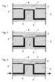
- Fig. 2is shown schematically the closed state of a single thermal valve cell.
- the heat sink 8remains in constant operation while the heating element 7 is turned off. As a result, it comes at the contact point 5 of the channel 4, which is at this point the heat sink 8 closest to a local icing of the channel 4, whereby the guided through the channel 4 liquid is frozen and thus as an accurate closure element 9 of the channel 4th serves.
- FIG. 3As in Fig. 3 is shown to open the valve cell Heating element 7 is acted upon via the electrical conductor track structure 6 with electricity, whereby it heats up. This will do the in Fig. 2 illustrated trained closure element 9, which formed due to the local icing of the channel 4 at the contact point 5 , dissolved, the heat dissipation from the contact point 5 is compensated by the heat sink 8 . The microfluidic channel 4 is thereby opened again and the liquid can flow through the valve.
- Fig. 4schematically shows the structure of a 3bit fluidic multiplexer, which initially consists of the same components as used for the single thermal valve cell in Fig. 1 described.
- This arrangementalso includes a heat sink 8, a microfluidic body 3 (not shown here) and a board 2 (not shown here), which is not only a single Heating element 7 is located on a single wiring pattern 6 , but a plurality of heating elements 40-1 to 40-4, 41-1 to 41-4, 42-1 to 42-4, 43-1 to 43-4, 44-1 to 44-4 and 45-1 to 45-4, which are distributed here over a total of 6 individual tracks 40 to 45 , which are combined in pairs (tracks 40, 41 and 42, 43 and 44, 45) .
- the elements 40 to 45 of the said pairsare each assigned a logic switching state: the tracks 40, 42, 44 form the logical TRUE lines, while the tracks 41, 43, 45 form the logical FALSE lines.
- Each a logical TRUE line and a logical FALSE lineresult in a control line in sum:
- the lines 40, 41form the 2 0 control line 50, the lines 42, 43, the 2 1 control line 51, while the lines 44, 45, the 2 2 control line 52 form.
- the control lines 50 to 52each know the logical switching state TRUE or FALSE.
- the control line 2 0is in the state TRUE, the conductor 40 must be energized, in consequence, the heating elements 40-1 to 40-4 would heat.
- the control line 2 0is in the state FALSE, the conductor path has to be applied to 41 with electricity, as a result, the heating elements will heat up 41-1 to 41-4.
- a control line 50 to 52can thus always represent either the switching state TRUE or FALSE, never both; Thus, only one of the two associated tracks is always under tension.
- Each of the channels 9 to 16has a correspondingly executed inflow 17 to 24 and a correspondingly executed outflow 25 to 32 on.
- the arrangementis designed so that the individual microfluidic channels 9 to 16 analogous to those in Fig. 1 represented thermal contact point 5 between the channel 4 and the heat sink 8 and the electrical wiring structure 6 are.
- the body of the 3-bit fluidic multiplexeris designed so that the in Fig. 4 shown three-part contact zone coupled to the heat sink 8 .
- Fig. 5schematically shows a three-dimensional design of the 3bit fluidic multiplex, which is analogous to the structure of the individual thermal valve cell.
- the heat sink 8 and the board 2are shown.
- Fig. 6the 3bit fluidic multiplexer is shown in the closed normal state.
- the individual thermal valve cell of the heat sink 8is operated constantly, while the individual microfluidic channels 9, 10 at their contact points with the heat source, ie in each case at the points where the heat sources 40-1 to 40-4, 41st -1 to 41-4, 42-1 to 42-4, 43-1 to 43-4, 44-1 to 44-4 and 45-1 to 45-4 are arranged freeze and thus by local icing in each case a closure element 60 training.
- Fig. 7is shown how can be opened by applying a digital signal to the 2 0 to 2 2 control lines 50 to 52 one of the microfluidic channels 9-16 .
- the binary signal 101corresponding to the number 5 in decimal notation, is used as an example.
- a logical TRUEis applied to the 2 2 control line 52 , a logical FALSE to the 2 1 control line 51 and a logical TRUE to the 2 0 control line 50 .
- the tracks 40, 43 and 44are put under tension and the heating elements connected thereto 40-1 to 40-4, 43-1 to 43-4 and 44-1 to 44-4 heat up.
- Fig. 8shows what happens when above the heated heating elements, the local icing melted and the microfluidic channels in this area are again through.
- Each microfluidic channelmust pass through all three control lines 50 to 52 . Only when each of the crossing points of the respective channel is opened with each of the three control lines can flow from the inlet of the respective microfluidic channel to the outlet of the respective microfluidic channel be established.
- the design of the fluidic multiplexerensures that only a single microfluidic channel - im in Fig. 7 sketched case the channel 14 or # 5, analogous to the digital control signal 101 - is open at all three crossing points. All remaining microfluidic channels are still frozen at at least one of the crossing points between the respective channel and one of the control lines 50 to 52 and thus closed.
- microfluidic multiplexerhas the great advantage that the number of controllable microfluidic channels increases exponentially: Each additional control line doubles the number of controllable channels. Such complexity can not be achieved by a simple 1-to-1 control, as implemented in almost all microfluidic valve systems.
Landscapes
- Chemical & Material Sciences (AREA)
- Engineering & Computer Science (AREA)
- Dispersion Chemistry (AREA)
- Health & Medical Sciences (AREA)
- General Engineering & Computer Science (AREA)
- Analytical Chemistry (AREA)
- Clinical Laboratory Science (AREA)
- Chemical Kinetics & Catalysis (AREA)
- Hematology (AREA)
- General Health & Medical Sciences (AREA)
- Mechanical Engineering (AREA)
- Micromachines (AREA)
- Temperature-Responsive Valves (AREA)
- Apparatus Associated With Microorganisms And Enzymes (AREA)
Abstract
Translated fromGerman
Description
Translated fromGermanDie Erfindung betrifft eine Vorrichtung zum Steuern des Durchflusses von Fluiden durch mikrofluidische Kanäle, ein Verfahren zu ihrem Betrieb und ihre Verwendung.The invention relates to a device for controlling the flow of fluids through microfluidic channels, a method for their operation and their use.
In vielen Anwendungen von mikrofluidischen Systemen ist es erforderlich, eine sehr hohe Anzahl von mikrofluidischen Kanälen zu steuern, um verschiedene Analyse- oder Syntheseschritte in einem System oder einem Prozess zu steuern.In many applications of microfluidic systems, it is necessary to control a very large number of microfluidic channels to control various analysis or synthesis steps in a system or process.
In der
Solche Systeme sind weder durch kleine implementierte konventionelle Ventile und auch nicht durch direkt anzusteuernde Mikroventile robust zu betreiben, da die Steuerungstechnik bei einer so großen Anzahl von Ventilen sehr komplex wird. Darüber hinaus steigt auch die Baugröße solcher Systeme sehr schnell unverhältnismäßig an.Such systems can not be operated robustly either by means of small conventional valves or by directly actuated microvalves, since the control technology becomes very complex with such a large number of valves. In addition, the size of such systems increases disproportionately very quickly.
Die
Diese Systeme setzen eine 1-zu-1 Steuerung voraus, d. h. die Ventile werden jeweils einzeln geöffnet und wieder geschlossen, so dass jedem Ventil eine eigene Steuerleitung zugeordnet werden kann. Der Vorteil im Vergleich zu Systemen, die auf bewegten mechanischen Komponenten wie Membranen oder Piezoaktoren basieren, besteht darin, dass die thermischen Ventile passiv arbeiten, wodurch sie viel robuster, weniger fehleranfällig und damit stabiler im Betrieb sind. Vor allem in Bezug auf Fertigungstoleranzen und Passungen sind thermische Ventile der herkömmlichen Ventiltechnik überlegen. Die Erzeugung des blockierenden Volumens erfolgt intrinsisch passgenau, damit sind keine Undichtigkeiten der Ventile durch ungenaue Formpassungen möglich, was insbesondere bei miniaturisierten mikrofluidischen Ventilen in konventioneller Bautechnik ein großes Problem darstellt. Insbesondere ist ein Ventil so ausgeführt, dass Wärmequelle und -senke vom mikrofluidischen Kanal entkoppelt sind. Der mikrofluidische Kanal ist dann für sich abgeschlossen und auf einer separaten Komponente ausgeführt, Wärmequelle und -senke können wieder verwendet werden, wenn der mikrofluidische Kanal entsorgt wird, beispielsweise weil er verunreinigt oder verschlossen ist. Darüber hinaus sind diese Ventile auch günstiger in der Herstellung, da sie keine eigentlichen Ventilkomponenten besitzen. Die Ventilfunktion wird vielmehr durch bereits im System vorliegende Stoffe, nämlich dem Inhalt des mikrofluidischen Kanals realisiert. Ein weiterer Vorteil dieser Systeme liegt darin, dass sie unabhängig vom gewählten Material des mikrofluidischen Kanals sind. Das Material kann an die jeweils geforderte Anwendung angepasst werden und kann, beispielsweise in Kunststoff, Keramik oder Silizium ausgeführt sein. Unabhängig von der Wahl des Materials ist die beschrieben thermische Ventiltechnik auf alle Materialien übertragbar, da das Ventil lediglich den Inhalt des Kanals für die Ventilfunktion ausnutzt.These systems require a 1-to-1 control, ie the valves are opened and closed individually, so that each valve can be assigned its own control line. The advantage over systems based on moving mechanical components such as diaphragms or piezo actuators is that the thermal valves are passive, making them much more robust, less prone to failure, and more stable in operation. Especially in terms of manufacturing tolerances and fits thermal valves are superior to conventional valve technology. The generation of the blocking volume is intrinsically accurate fit, so that no leaks of the valves are possible due to inaccurate form fits, which is a big problem especially in miniaturized microfluidic valves in conventional construction. In particular, a valve is designed so that the heat source and sink are decoupled from the microfluidic channel. The microfluidic channel is then self-contained and implemented on a separate component, heat source and sink can be reused when disposing of the microfluidic channel, for example because it is contaminated or occluded. In addition, these valves are also cheaper to manufacture, since they have no actual valve components. Rather, the valve function is realized by substances already present in the system, namely the contents of the microfluidic channel. Another advantage of these systems is that they are independent of the selected material of the microfluidic channel. The material can be adapted to the particular application required and can, for example in plastic, ceramic or silicon. Regardless of the choice of material, the described thermal valve technology is transferable to all materials, since the valve only exploits the contents of the channel for the valve function.
Im beschriebenen Zustand können thermische Ventile eingesetzt werden, um an bestimmten Stellen in mikrofluidischen Systemen Kanäle zu verschließen oder zu öffnen. Ist die Anzahl der zu steuernden Kanäle allerdings sehr groß (im Bereich Hunderte bis Tausende), so würden sich thermische Ventile genauso wenig eignen wie jedes andere Ventil, welches auf 1-zu-1 Steuerung ausgelegt ist. Der Steueraufwand für ein solches System ist einfach zu groß.In the described state, thermal valves can be used to close or open channels at certain points in microfluidic systems. However, if the number of channels to be controlled is very large (in the range of hundreds to thousands), then thermal valves would be just as unlikely as any other valve, which is designed for 1-to-1 control. The tax expense for such a system is just too big.
In der
Ein fluidischer Multiplexer in klassischer Ventiltechnik erhöht somit die Fehleranfälligkeit des Systems erheblich, da für jedes einzelne Ventil eine gewisse Wahrscheinlichkeit besteht, dass es nach dem Fertigungsprozess fehlerhaft ist. Für den in der
Darüber hinaus besitzen alle beschriebenen fluidischen Multiplexer ein Problem: Die Struktur der Ventile und der Aktorik ist intrinsisch mit der mikrofluidischen Struktur verbunden. Soll die mikrofluidische Kanalstruktur entsorgt werden, z.B. weil die Struktur kontaminiert oder verstopft ist, muss damit immer auch die gesamte Aktorik entsorgt werden, da diese fest mit der mikrofluidischen Struktur verbunden ist. Diese Bedingung verringert die Zuverlässigkeit dieser Systeme weiter und macht sie vor allem für Anwendungen ungeeignet, die ein häufiges Auswechseln der Kanalstruktur erfordern, insbesondere biomedizinische Anwendungen, die verlangen, dass alle Systemkomponenten, die einmal in Kontakt mit einem Analyten standen, nach jeder Messung ausgewechselt werden müssen.In addition, all described fluidic multiplexers have a problem: the structure of the valves and the actuators is intrinsically linked to the microfluidic structure. If the microfluidic channel structure is to be disposed of, eg because the structure is contaminated or clogged, the entire actuator system must always be disposed of, because it is firmly connected to the microfluidic structure. This condition It further reduces the reliability of these systems and makes them particularly unsuitable for applications requiring frequent channel structure replacement, particularly biomedical applications requiring that all system components once in contact with an analyte be replaced after each measurement.
Ausgehend hiervon ist es die Aufgabe der vorliegenden Erfindung, eine Vorrichtung zum Steuern des Durchflusses von Fluiden durch mikrofluidische Kanäle, ein Verfahren zu ihrem Betrieb und ihre Verwendung vorzuschlagen, die die genannten Nachteile und Einschränkungen nicht aufweisen.Based on this, it is the object of the present invention to provide a device for controlling the flow of fluids through microfluidic channels, a method for their operation and their use, which do not have the mentioned disadvantages and limitations.
Insbesondere soll eine Vorrichtung bereitgestellt werden, die es ermöglicht, eine große Anzahl von mikrofluidischen Kanälen mit einer möglichst geringen Anzahl von Steuerleitungen zu steuern.In particular, a device is to be provided which makes it possible to control a large number of microfluidic channels with the smallest possible number of control lines.
Diese Aufgabe wird im Hinblick auf die Vorrichtung durch die Merkmale des Anspruchs 1, im Hinblick auf das Verfahren durch die Verfahrensschritte des Anspruchs 6 und im Hinblick auf die Verwendung durch den Anspruch 8 gelöst. Die Unteransprüche beschreiben jeweils vorteilhafte Ausgestaltungen der Erfindung.This object is achieved with regard to the device by the features of
Eine erfindungsgemäße Vorrichtung zum Steuern des Durchflusses von Fluiden durch n= 2m mikrofluidische Kanäle, wobei m eine natürliche Zahl > 0 ist, ist in ein Substrat eingebracht und derart ausgestaltet, dass jeder Kanal jeweils m Kontaktstellen mit jeweils einem Heizelement aufweist. Die Heizelemente sind bevorzugt als Ohmscher Widerstand oder als Diode ausgestaltet.An inventive device for controlling the flow of fluids through n= 2m microfluidic channels, where m is a natural number> 0, is introduced into a substrate and configured such that each channel has m contact points, each with a heating element. The heating elements are preferably configured as an ohmic resistance or as a diode.
Hierbei ist für jeweils die erste Hälfte der Kanäle das mit diesem Kanal in Kontakt stehende Heizelement für jede der m Kontaktstellen durch eine erste Leiterbahn mit jeweils einem Heizelement der anderen Kanäle verbunden und für die jeweils andere Hälfte der Kanäle das mit diesem Kanal in Kontakt stehende Heizelement für jede der m Kontaktstellen durch eine zweite Leiterbahn mit jeweils einem Heizelement der anderen Kanäle verbunden. Vorzugsweise sind die Kanäle derart ausgestaltet sind, dass sie an einer Kontaktstelle gegen die Platine geöffnet oder mittels einer dünnen Wand, die eine geringe thermische Kapazität aufweist, gegenüber der Platine abgeschlossen sind.In this case, for each of the first half of the channels, the heating element in contact with this channel is connected for each of the m contact points by a first conductor track, each with a heating element of the other channels, and for the respective ones other half of the channels connected to this channel in contact heating element for each of the m contact points by a second conductor, each with a heating element of the other channels. Preferably, the channels are configured such that they open at a contact point against the board or by means of a thin wall, which has a low thermal capacity, are completed with respect to the board.
Weiterhin bilden jeweils eine erste Leiterbahn und eine zweite Leiterbahn, paarweise zusammengefasst, jeweils eine Steuerleitung, für die entweder nur der Schaltzustand TRUE oder nur der Schaltzustand FALSE einstellbar ist.Furthermore, each form a first trace and a second trace, in pairs, each having a control line, for which either only the switching state TRUE or only the switching state FALSE is adjustable.
Fluidische Multiplexer ermöglichen es, über eine kleine Anzahl von Steuerleitungen eine große Anzahl von fluidischen Kanälen zu schalten. Sie bedienen sich dabei eines Konzeptes, das aus der Elektronik bekannt ist. Multiplexer beschalten eine große Anzahl von Signalleitungen mit einer kleinen Anzahl von Steuerleitungen, wobei die beiden Größen in exponentiellem Zusammenhang zueinander stehen:
Anzahl Signalleitungen = 2 hoch (Anzahl Steuerleitungen)Fluidic multiplexers make it possible to switch a large number of fluidic channels over a small number of control lines. They use a concept that is known from electronics. Multiplexers connect a large number of signal lines to a small number of control lines, the two quantities being exponentially related to each other:
Number of signal lines = 2 high (number of control lines)
Ein3bit fluidischer Multiplexer wäre somit in der Lage 23 = 8 mikrofluidische Kanäle zu schalten, ein10bit fluidischer Multiplexer sogar 210 = 1024. Das Konzept lässt sich mühelos auf eine beliebige Anzahl von Steuerleitungen erweitern, womit sich mühelos Tausende von mikrofluidischen Kanälen steuern lassen.A3-bit fluidic multiplexer would thus be able to switch 23 = 8 microfluidic channels, a10-bit fluidic multiplexer even 210 = 1024. The concept can easily be extended to any number of control lines, allowing effortless control of thousands of microfluidic channels ,
Schließlich befinden sich die Leiterbahnen und die Heizelemente auf einer Platine, die an ein Kühlelement angrenzt. Das Kühlelement liegt bevorzugt in Form einer Kühlrippenstruktur mit einer angeschlossenen Heatpipe, eines Ventilationssystems oder eines Peltier-Elements vor.Finally, the tracks and the heating elements are located on a board adjacent to a cooling element. The cooling element is preferably in the form of a cooling rib structure with a connected heat pipe, a ventilation system or a Peltier element.
Eine erfindungsgemäße Vorrichtung lässt sich mit dem folgenden Verfahren betreiben.A device according to the invention can be operated with the following method.
Erfindungsgemäß wird eine passive Umsetzung eines mikrofluidischen Multiplexers, der auf thermischer Ventiltechnik beruht, vorgeschlagen. Die Funktion desÖffnens und desSchließens eines mikrofluidischen Kanals wird dabei nicht durch eine mechanisch bewegliche, eventuell mikrotechnisch hergestellte Komponente realisiert, sondern durch das lokale Einfrieren und Öffnen eines Kanals mittels einer Wärmequelle und einer Wärmesenke.According to the invention, a passive implementation of a microfluidic multiplexer based on thermal valve technology is proposed. The function ofopening andclosing a microfluidic channel is not realized by a mechanically movable, possibly microfabricated component, but by the local freezing and opening of a channel by means of a heat source and a heat sink.
Das erfindungsgemäße Verfahren zum Steuern des Durchflusses eines Fluids durchn =2m mikrofluidische Kanäle, wobei m eine natürliche Zahl > 0 ist und die Kanäle in ein Substrat eingebracht sind, weist die Schritte a) bis c) auf.The method according to the invention for controlling the flow of a fluid throughn =2m microfluidic channels, where m is a natural number> 0 and the channels are introduced into a substrate, comprises the steps a) to c).
Gemäß Schritt a) werden zunächst die mikrofluidischen Kanäle an ihren Kontaktstellen mit den Heizelementen eingefroren. Die Kontaktstellen bilden somit jeweils ein Verschlusselement für die mikrofluidischen Kanäle aus.According to step a), first the microfluidic channels are frozen at their contact points with the heating elements. The contact points thus each form a closure element for the microfluidic channels.
Dann wird gemäß Schritt b) ein digitales Signal an die Steuerleitungen, wobei jede Steuerleitung nur entweder den Schaltzustand TRUE oder FALSE annimmt, so dass nur jeweils eine der beiden zugeordneten Leiterbahnen unter Spannung steht, angelegt. Nur, wenn jeder der Kreuzungspunkte des jeweiligen Kanals mit jeder der Steuerleitungen durch Anlegen des Schaltzustands TRUE geöffnet ist, taut ein Heizelement am betreffenden Kreuzungspunkt an seiner Kontaktstelle den mikrofluidischen Kanal auf und der betreffende mikrofluidische Kanal öffnet sich, wodurch sich ein Fluss vom Einlass des jeweiligen mikrofluidischen Kanals zum Auslass des jeweiligen mikrofluidischen Kanals ausbilden könnte.Then, according to step b), a digital signal is applied to the control lines, wherein each control line only assumes either the switching state TRUE or FALSE, so that only one of the two associated tracks is energized. Only when each of the crossing points of the respective channel is opened with each of the control lines by applying the switching state TRUE, a heating element at the point of intersection at its point of contact thaws the microfluidic channel and the respective microfluidic channel opens, whereby a flow from the inlet of the respective microfluidic Channel could form to the outlet of the respective microfluidic channel.
Gemäß Schritt c) wird schließlich bevorzugt durch eine oder mehrere externe Pumpen ein Fluss vom Einlass des jeweiligen mikrofluidischen Kanals zum Auslass des jeweiligen mikrofluidischen Kanals angelegt.Finally, according to step c), one or more external pumps preferably apply a flow from the inlet of the respective microfluidic channel to the outlet of the respective microfluidic channel.
Eine erfindungsgemäße Vorrichtung lässt sich einsetzen für die Schaltung von hoch komplexen Mikrofluidiken mit Hunderten bis Tausenden von mikrofluidischen Kanälen.A device according to the invention can be used for the switching of highly complex microfluidics with hundreds to thousands of microfluidic channels.
Daneben eignet sich diese Vorrichtung auch für die Steuerung von Gasflüssen. Ist der fluidische Multiplexer in Betrieb und wurde eine der genannten zu schaltenden mikrofluidischen Kanäle geöffnet, so kann durch diesen Kanal nicht nur eine Flüssigkeit, sondern auch ein Gas gefördert werden.In addition, this device is also suitable for the control of gas flows. If the fluidic multiplexer is in operation and one of said microfluidic channels to be switched has been opened, not only a liquid but also a gas can be conveyed through this channel.
Die Erfindung weist insbesondere die im Folgenden erwähnten Vorteile auf.The invention has in particular the advantages mentioned below.
Die erfindungsgemäße Vorrichtung übertrifft durch den, dem Multiplexen intrinsischen exponentiellen Zusammenhang zwischen Steuerleitungen und mikrofluidischen Kanälen, jedes Ventil, das durch Einzelsteuerung betrieben wird. Komplexe mikrofluidische Systeme, die durch Ventile in Einzelbetriebsteuerung beschaltet werden, können nicht in dieser Kompaktheit umgesetzt werden; alleine die Vielzahl an Zuleitungen für die Ventilsteuerung würde das System inakzeptabel vergrößern.The device according to the invention exceeds any valve which is operated by individual control by virtue of the multiplexing intrinsic exponential relationship between control lines and microfluidic channels. Complex microfluidic systems, which are connected by valves in single-operation control, can not be implemented in this compactness; just the multitude of valve control leads would unacceptably increase the system.
Für die erfindungsgemäße Vorrichtung ist keine Aktorik notwendig, es werden keine mechanisch bewegten Komponenten, keine zu deflektierende Membrane oder ähnliches benötigt. Die Vorrichtung beruht vielmehr auf rein passiver thermischer Ventiltechnik, was die in der Herstellung sehr preiswert und im Betrieb sehr robust macht.No actuator system is necessary for the device according to the invention, no mechanically moved components, no diaphragm to be deflected or the like are needed. Rather, the device is based on purely passive thermal valve technology, which is very inexpensive to manufacture and in operation makes it very sturdy.
In der erfindungsgemäßen Vorrichtung sind die mikrofluidische Kanalstruktur und die eigentliche Ventillogik voneinander getrennt ausgestaltet. Beide Komponenten können somit getrennt voneinander ausgeführt werden, ihre jeweiligen Herstellungsprozesse getrennt optimiert werden. Funktioniert eine der beiden Komponenten, so kann jeweils die andere beibehalten werden. Dies ist vor allem daher interessant, weil die mikrofluidische Struktur, vor allem wenn sie für biomedizinische Anwendungen eingesetzt werden soll, häufig ausgetauscht werden muss. Sie macht aber nun den geringsten Teil der Kosten des Gesamtsystems aus, die eigentlichen Kosten entstehen durch die Ventillogik, d.h. Wärmequellen und -senken sowie deren Ansteuerung, die sich aber wieder verwenden lässt, da sie im Betrieb nicht kontaminiert.In the device according to the invention, the microfluidic channel structure and the actual valve logic are configured separately from one another. Both components can thus be carried out separately, their respective manufacturing processes can be optimized separately. If one of the two components works, the other one can be retained. This is particularly interesting because the microfluidic structure, especially if it is to be used for biomedical applications, must be frequently replaced. But it now accounts for the least part of the cost of the entire system, the actual costs are caused by the valve logic, i. Heat sources and sinks and their control, but which can be used again because it does not contaminate during operation.
Die erfindungsgemäße Vorrichtung ist beliebig skalierbar: Für die Herstellung von Wärmequellen auf elektronischen Schaltungen existieren bereits heute eine Vielzahl von Fertigungsprozessen (z. B. Siebdruck von Widerständen), die nicht auf eine bestimmte Fläche beschränkt ist (Endlos- oder Offsetdruck). Für die Wärmesenken gilt ähnliches. Somit ist das System auf eine beliebige Anzahl mikrofluidischer Kanäle expandierbar, ohne einer fertigungstechnischen Beschränkung zu unterliegen.The device according to the invention can be scaled arbitrarily: For the production of heat sources on electronic circuits, a large number of production processes already exist (eg screen printing of resistors) which is not limited to a specific area (continuous or offset printing). The same applies to the heat sinks. Thus, the system is expandable to any number of microfluidic channels without being subject to manufacturing constraints.
Es sind keine besonderen physikalischen Rahmenbedingungen notwendig, insbesondere wird keine Druckluft benötigt. Lediglich Strom für die Heizelemente und einen Peltier-Block als Kältequelle ist erforderlich.There are no special physical conditions necessary, in particular no compressed air is needed. Only electricity for the heating elements and a Peltier block as a source of cold is required.
Ein weiterer Vorteil besteht darin, dass das Wärmemanagement im geöffneten Zustand des Ventils sehr genau bekannt ist, da die Temperatur des Heizelementes bekannt ist, wenn geeignete Heizelemente, bevorzugt ein Widerstand mit bekannter Temperatur-Widerstands-Kennlinie, z. B. ein Halbleiter PTC oder ein Platin-Heizelement, eingesetzt wird. Die exakte Temperierung der geführten Flüssigkeiten stellt einen Mehrwert dar.Another advantage is that the heat management in the open state of the valve is very well known, since the temperature of the heating element is known, if suitable heating elements, preferably a resistor with a known temperature-resistance characteristic, z. As a semiconductor PTC or a platinum heating element is used. The exact temperature of the guided liquids is an added value.
Die Erfindung wird im Folgenden anhand von Ausführungsbeispielen und den Figuren näher erläutert. Es zeigen:
- Fig. 1
- Aufbau einer einzelnen thermischen Ventilzelle;
- Fig. 2
- Ventilzelle imgeschlossener Zustand;
- Fig. 3
- Ventilzelle im geöffnetenZustand;
- Fig. 4
- Funktionsweise eines 3bit fluidischen Multiplexer;
- Fig. 5
- Aufbau eines 3bit fluidischen Multiplexers;
- Fig. 6
- 3bit fluidischen Multiplexers imgeschlossenen Zustand;
- Fig. 7
- 3bit fluidischen Multiplexers nach Anlagen des digita- len Steuersignals 101;
- Fig. 8
- wie
Fig. 7 , mit Darstellung der vereist bleibenden Be- reiche.
- Fig. 1
- Structure of a single thermal valve cell;
- Fig. 2
- Valve cell in theclosed state;
- Fig. 3
- Valve cell in the openedstate;
- Fig. 4
- Functioning of a 3bit fluidic multiplexer;
- Fig. 5
- Construction of a 3bit fluidic multiplexer;
- Fig. 6
- 3bit fluidic multiplexer in theclosed state;
- Fig. 7
- 3bit fluidic multiplexer according to systems of the digital control signal 101;
- Fig. 8
- as
Fig. 7 , with representation of the iced areas.
Auf der Rückseite der Platine2 befindet sich vorzugsweise in flächiger Bauweise ein Kühlkörper8, der als Wärmesenke in der Ventilzelle dient. Ein derartiger Kühlkörper besteht bevorzugt in einer Kühlrippenstruktur mit einer angeschlossenen Heatpipe, einem Ventilationssystem oder einem Peltier-Element. Alternativ wird eine physikalische oder chemische Kältequelle, z.B. eine endotherme Reaktion, Kühlbehälter mit flüssigem Stickstoff oder einem anderen Gas, eingesetzt. Der Kühlkörper8 ist derart auf der Platine2 aufgesetzt, dass die beiden Komponenten einen möglichst geringen thermischen Widerstand zueinander ausbilden.On the back of the
Die erfindungsgemäße thermische Ventilzelle wird, wie in den
In
Wie in
Ausgehend vom Aufbau einer einzelnen thermischen Ventilzelle wird im Folgenden das Konzept des fluidischen Multiplexens beispielhaft beschrieben, das das freie Beschalten einer Vielzahl von fluidischen Kanälen ermöglicht. Das Konzept des Multiplexens ist aus der Elektronik bekannt. Multiplexer werden dazu eingesetzt, um eine große Anzahl von Signalleitungen mit einer geringen Anzahl an Steuerleitungen zu beschalten. Dabei gilt der exponentielle Zusammenhang, dass sich mit n Steuerleitungen 2n Signalleitungen beschalten lassen. Im Falle eines3bit-Multiplexers ist so die Steuerung von 23=8 Signalleitungen möglich, bei einem10bit-Multiplexers bereits die Steuerung von 210=1024 Signalleitungen. Ein mikrofluidischer Multiplexer leistet Vergleichbares für die Fluidik. Eine Signalleitung entspricht hierbei einem zu steuernden mikrofluidischem Kanal, z. B. Kanal4 aus
Die Elemente40 bis 45 der genannten Paare sind jeweils einem logischen Schaltzustand zugeordnet: Die Leiterbahnen40, 42, 44 bilden die logischen TRUE Leitungen, während die Leiterbahnen41, 43, 45 die logischen FALSE Leitungen bilden. Jeweils eine logische TRUE Leitung und eine logisch FALSE Leitung ergeben in Summe eine Steuerleitung: Die Leitungen40, 41 bilden die 20 Steuerleitung50, die Leitungen42, 43 die 21 Steuerleitung51, während die Leitungen44, 45 die 22 Steuerleitung52 bilden.The
Die Steuerleitungen50 bis 52 kennen jeweils den logischen Schaltzustand TRUE oder FALSE. Damit sich z.B. die Steuerleitung 20 im Zustand TRUE befindet, muss die Leiterbahn40 mit Strom beaufschlagt werden, in Folge würden die Heizelemente40-1 bis 40-4 heizen. Damit sich die Steuerleitung 20 jedoch im Zustand FALSE befindet, muss die Leiterbahn41 mit Strom beaufschlagt werden, in Folge würden die Heizelemente41-1 bis 41-4 heizen. Eine Steuerleitung50 bis 52 kann so immer nur entweder den Schaltzustand TRUE oder FALSE darstellen, niemals beide; somit ist immer nur jeweils eine der beiden zugeordneten Leiterbahnen unter Spannung.The control lines50 to 52 each know the logical switching state TRUE or FALSE. Thus, for example, the
Im Unterschied zur einzelnen thermischen Ventilzelle besitzt der 3bit fluidische Multiplexer auch eine erhöhte Anzahl an zu schaltenden mikrofluidischen Kanälen, nämlich 23 = 8 Kanäle9 bis 16, die auch mit#0 bis #7 bezeichnet werden. Jeder der Kanäle9 bis 16 weist einen entsprechend ausgeführten Zufluss17 bis 24 und einen entsprechend ausgeführten Abfluss25 bis 32 auf. Die Anordnung ist so ausgeführt, dass die einzelnen mikrofluidischen Kanäle9 bis 16 analog zu der in
Im Folgenden wird der Betrieb der erfindungsgemäßen Anordnung am Beispiel eines 3bit fluidische Multiplexers beschrieben.The operation of the arrangement according to the invention is described below using the example of a 3-bit fluidic multiplexer.
In
In
Eine solche Anordnung ist somit in der Lage über eine rein passive Vorrichtung eine nahezu beliebige Anzahl von mikrofluidischen Kanälen zu beschalten. Im Vergleich zur einzelnen thermischen Ventilzelle, bei der jeder einzelnen Ventilzelle eine einzelne Steuerleitung zugeordnet wird, besitzt der mikrofluidische Multiplexer den großen Vorteil, dass die Anzahl an steuerbaren mikrofluidischen Kanälen exponentiell zunimmt: Jede weitere Steuerleitung verdoppelt die Anzahl steuerbarer Kanäle. Eine solche Komplexität lässt sich durch eine einfache 1-zu-1-Steuerung, wie sie in nahezu allen mikrofluidischen Ventilsystemen implementiert ist, nicht erreichen.Such an arrangement is thus able to connect via a purely passive device almost any number of microfluidic channels. Compared to the single thermal valve cell, in which each individual valve cell is assigned a single control line, the microfluidic multiplexer has the great advantage that the number of controllable microfluidic channels increases exponentially: Each additional control line doubles the number of controllable channels. Such complexity can not be achieved by a simple 1-to-1 control, as implemented in almost all microfluidic valve systems.
Claims (7)
Translated fromGermanApplications Claiming Priority (1)
| Application Number | Priority Date | Filing Date | Title |
|---|---|---|---|
| DE102009035292ADE102009035292A1 (en) | 2009-07-30 | 2009-07-30 | Device for controlling the flow of fluids through microfluidic channels, methods of their operation and their use |
Publications (2)
| Publication Number | Publication Date |
|---|---|
| EP2279789A2true EP2279789A2 (en) | 2011-02-02 |
| EP2279789A3 EP2279789A3 (en) | 2013-07-17 |
Family
ID=43303704
Family Applications (1)
| Application Number | Title | Priority Date | Filing Date |
|---|---|---|---|
| EP20100007420WithdrawnEP2279789A3 (en) | 2009-07-30 | 2010-07-17 | Device for controlling the throughput of fluids through microfluid channels, method for operating same and application of same |
Country Status (3)
| Country | Link |
|---|---|
| US (1) | US8480974B2 (en) |
| EP (1) | EP2279789A3 (en) |
| DE (1) | DE102009035292A1 (en) |
Cited By (2)
| Publication number | Priority date | Publication date | Assignee | Title |
|---|---|---|---|---|
| WO2014016562A1 (en)* | 2012-07-26 | 2014-01-30 | Atomjet Limited | Micro pumps |
| EP2924531A3 (en)* | 2014-03-25 | 2015-11-18 | Robert Bosch Gmbh | Microfluidic device and method for controlling a fluid flow in a microfluidic device |
Families Citing this family (8)
| Publication number | Priority date | Publication date | Assignee | Title |
|---|---|---|---|---|
| DE102009035291B4 (en)* | 2009-07-30 | 2011-09-01 | Karlsruher Institut für Technologie | Device for producing a microfluidic channel structure in a chamber, method for its production and its use |
| US9989049B2 (en)* | 2015-12-11 | 2018-06-05 | Funai Electric Co., Ltd. | Microfluidic pump |
| EP3623049A1 (en)* | 2018-09-12 | 2020-03-18 | Sharp Life Science (EU) Limited | Microfluidic device and a method of loading fluid therein |
| USD919833S1 (en) | 2019-03-06 | 2021-05-18 | Princeton Biochemicals, Inc | Micro valve for controlling path of fluids in miniaturized capillary connections |
| CN110107736B (en)* | 2019-05-06 | 2024-04-16 | 中国科学院理化技术研究所 | Phase-change micro-valve device |
| EP3763438A1 (en)* | 2019-07-12 | 2021-01-13 | Curiosity Diagnostics sp. z o.o | Microfluidic chip, production process and uses |
| GB202005633D0 (en)* | 2020-04-17 | 2020-06-03 | Univ Court Univ Of Glasgow | Fluid handling device and methods |
| WO2022191832A1 (en)* | 2021-03-10 | 2022-09-15 | Hewlett-Packard Development Company, L.P. | Microfluidic sample compartment arrays |
Citations (8)
| Publication number | Priority date | Publication date | Assignee | Title |
|---|---|---|---|---|
| US3599525A (en) | 1970-05-14 | 1971-08-17 | Paul A Klann | Pneumatic crossbar device |
| EP0368306B1 (en) | 1988-11-11 | 1995-04-05 | Hitachi, Ltd. | Apparatus for and method of controlling the opening and closing of channel for liquid |
| US5775371A (en) | 1995-03-08 | 1998-07-07 | Abbott Laboratories | Valve control |
| EP0731303B1 (en) | 1995-02-13 | 1999-09-01 | Bio Merieux | Static freezing valve and a treatment chamber with such a valve |
| US6202687B1 (en) | 1997-10-18 | 2001-03-20 | Bioneer Corporation | Matrix multiple valve system |
| US6575188B2 (en) | 2001-07-26 | 2003-06-10 | Handylab, Inc. | Methods and systems for fluid control in microfluidic devices |
| US7143785B2 (en) | 2002-09-25 | 2006-12-05 | California Institute Of Technology | Microfluidic large scale integration |
| DE102007032951A1 (en) | 2007-07-14 | 2009-01-15 | Forschungszentrum Karlsruhe Gmbh | Micro-fluid measurement cell, for a fluid with at least two components, has a fluid exchange between a branch channel inflow valve and the main channel to select the fluid components to pass into the cell |
Family Cites Families (6)
| Publication number | Priority date | Publication date | Assignee | Title |
|---|---|---|---|---|
| US6387234B1 (en)* | 1998-08-31 | 2002-05-14 | Iowa State University Research Foundation, Inc. | Integrated multiplexed capillary electrophoresis system |
| US6929030B2 (en)* | 1999-06-28 | 2005-08-16 | California Institute Of Technology | Microfabricated elastomeric valve and pump systems |
| US20020129664A1 (en)* | 2001-01-16 | 2002-09-19 | Jorgenson James W. | Non-invasive real-time flow meter and related flow measuring method |
| US7694694B2 (en)* | 2004-05-10 | 2010-04-13 | The Aerospace Corporation | Phase-change valve apparatuses |
| US7766033B2 (en) | 2006-03-22 | 2010-08-03 | The Regents Of The University Of California | Multiplexed latching valves for microfluidic devices and processors |
| WO2008115264A2 (en)* | 2006-09-11 | 2008-09-25 | California Institute Of Technology | Electrically actuated valves made from shape memory alloy wires embedded in elastomer |
- 2009
- 2009-07-30DEDE102009035292Apatent/DE102009035292A1/ennot_activeCeased
- 2010
- 2010-07-17EPEP20100007420patent/EP2279789A3/ennot_activeWithdrawn
- 2010-07-27USUS12/844,486patent/US8480974B2/ennot_activeExpired - Fee Related
Patent Citations (8)
| Publication number | Priority date | Publication date | Assignee | Title |
|---|---|---|---|---|
| US3599525A (en) | 1970-05-14 | 1971-08-17 | Paul A Klann | Pneumatic crossbar device |
| EP0368306B1 (en) | 1988-11-11 | 1995-04-05 | Hitachi, Ltd. | Apparatus for and method of controlling the opening and closing of channel for liquid |
| EP0731303B1 (en) | 1995-02-13 | 1999-09-01 | Bio Merieux | Static freezing valve and a treatment chamber with such a valve |
| US5775371A (en) | 1995-03-08 | 1998-07-07 | Abbott Laboratories | Valve control |
| US6202687B1 (en) | 1997-10-18 | 2001-03-20 | Bioneer Corporation | Matrix multiple valve system |
| US6575188B2 (en) | 2001-07-26 | 2003-06-10 | Handylab, Inc. | Methods and systems for fluid control in microfluidic devices |
| US7143785B2 (en) | 2002-09-25 | 2006-12-05 | California Institute Of Technology | Microfluidic large scale integration |
| DE102007032951A1 (en) | 2007-07-14 | 2009-01-15 | Forschungszentrum Karlsruhe Gmbh | Micro-fluid measurement cell, for a fluid with at least two components, has a fluid exchange between a branch channel inflow valve and the main channel to select the fluid components to pass into the cell |
Cited By (3)
| Publication number | Priority date | Publication date | Assignee | Title |
|---|---|---|---|---|
| WO2014016562A1 (en)* | 2012-07-26 | 2014-01-30 | Atomjet Limited | Micro pumps |
| US10018194B2 (en) | 2012-07-26 | 2018-07-10 | AtomJet Ltd. | Micro pumps |
| EP2924531A3 (en)* | 2014-03-25 | 2015-11-18 | Robert Bosch Gmbh | Microfluidic device and method for controlling a fluid flow in a microfluidic device |
Also Published As
| Publication number | Publication date |
|---|---|
| EP2279789A3 (en) | 2013-07-17 |
| DE102009035292A1 (en) | 2011-02-03 |
| US20110023971A1 (en) | 2011-02-03 |
| US8480974B2 (en) | 2013-07-09 |
Similar Documents
| Publication | Publication Date | Title |
|---|---|---|
| EP2279789A2 (en) | Device for controlling the throughput of fluids through microfluid channels, method for operating same and application of same | |
| DE102009035291B4 (en) | Device for producing a microfluidic channel structure in a chamber, method for its production and its use | |
| DE102017112803B4 (en) | Circuit arrangement for controlling a system and system with a circuit arrangement | |
| DE60119970T2 (en) | THROUGH ELECTRICALLY ACTIVE POLYMERS, OR VALVES ACTUATED THROUGH MOLDED MATERIALS, AND DEVICE AND METHOD OF USE THEREOF | |
| EP3592463B1 (en) | Method for centrifugo-pneumatic switching of liquid | |
| DE102011078770B4 (en) | Microfluidic device, microfluidic system and method of transporting fluids | |
| DE102016207845B4 (en) | Fluid handling device and method of fluid handling | |
| EP2531760A1 (en) | Micro-fluidic component for manipulating a fluid, and microfluidic chip | |
| EP1175258A1 (en) | Modular chemical microsystem | |
| EP2686595A1 (en) | Microfluidic valve and microfluidic platform | |
| EP0955473A1 (en) | Valve array | |
| EP3406340A1 (en) | Flow cell with housing component | |
| WO2011000738A1 (en) | Valve | |
| EP2828537B1 (en) | Bistable actuator, actuator assembly, method of actuation and use | |
| DE102004050510B4 (en) | Method for valve control in the thermocyclization of a substance for the purpose of PCR and associated arrangement | |
| EP1489404A1 (en) | Method for producing a 3-D microscope flowcell | |
| EP2783143A1 (en) | Microfluidic membrane-valve device, and a corresponding production method | |
| DE10222478A1 (en) | Microchip based analytical device can undertake e.g. liquid separation from a gas by movement of a flexible layer overlying a recess in the chip surface | |
| EP3029363B1 (en) | Fluidic device and method for operating the same | |
| DE102004062893A1 (en) | Electronically controllable hydrogel-based micropump | |
| DE102013207193A1 (en) | Microhydraulic system, especially for use in planar microfluidic laboratories | |
| DE102023202206A1 (en) | Sequential pumping using an actuator | |
| EP2924531B1 (en) | Microfluidic device and method for controlling a fluid flow in a microfluidic device | |
| DE102023202639A1 (en) | Fluidic module, fluid handling device and method with temporary pressure equalization in a pneumatic chamber | |
| DE3337095C2 (en) |
Legal Events
| Date | Code | Title | Description |
|---|---|---|---|
| PUAI | Public reference made under article 153(3) epc to a published international application that has entered the european phase | Free format text:ORIGINAL CODE: 0009012 | |
| AK | Designated contracting states | Kind code of ref document:A2 Designated state(s):AL AT BE BG CH CY CZ DE DK EE ES FI FR GB GR HR HU IE IS IT LI LT LU LV MC MK MT NL NO PL PT RO SE SI SK SM TR | |
| AX | Request for extension of the european patent | Extension state:BA ME RS | |
| PUAL | Search report despatched | Free format text:ORIGINAL CODE: 0009013 | |
| AK | Designated contracting states | Kind code of ref document:A3 Designated state(s):AL AT BE BG CH CY CZ DE DK EE ES FI FR GB GR HR HU IE IS IT LI LT LU LV MC MK MT NL NO PL PT RO SE SI SK SM TR | |
| AX | Request for extension of the european patent | Extension state:BA ME RS | |
| RIC1 | Information provided on ipc code assigned before grant | Ipc:F16K 99/00 20060101ALI20130610BHEP Ipc:B01L 3/00 20060101AFI20130610BHEP | |
| 17P | Request for examination filed | Effective date:20140117 | |
| RBV | Designated contracting states (corrected) | Designated state(s):AL AT BE BG CH CY CZ DE DK EE ES FI FR GB GR HR HU IE IS IT LI LT LU LV MC MK MT NL NO PL PT RO SE SI SK SM TR | |
| STAA | Information on the status of an ep patent application or granted ep patent | Free format text:STATUS: THE APPLICATION IS DEEMED TO BE WITHDRAWN | |
| 18D | Application deemed to be withdrawn | Effective date:20160202 |