EP2278321B1 - A sensor for measuring a target component in gaseous or liquid samples - Google Patents
A sensor for measuring a target component in gaseous or liquid samplesDownload PDFInfo
- Publication number
- EP2278321B1 EP2278321B1EP10184013.0AEP10184013AEP2278321B1EP 2278321 B1EP2278321 B1EP 2278321B1EP 10184013 AEP10184013 AEP 10184013AEP 2278321 B1EP2278321 B1EP 2278321B1
- Authority
- EP
- European Patent Office
- Prior art keywords
- electrolyte
- sensor
- electrode
- measuring
- ammonia
- Prior art date
- Legal status (The legal status is an assumption and is not a legal conclusion. Google has not performed a legal analysis and makes no representation as to the accuracy of the status listed.)
- Expired - Lifetime
Links
- 239000007788liquidSubstances0.000titleclaimsdescription10
- QGZKDVFQNNGYKY-UHFFFAOYSA-NAmmoniaChemical compoundNQGZKDVFQNNGYKY-UHFFFAOYSA-N0.000claimsabstractdescription112
- 239000003792electrolyteSubstances0.000claimsabstractdescription54
- 229910021529ammoniaInorganic materials0.000claimsabstractdescription49
- XLYOFNOQVPJJNP-UHFFFAOYSA-NwaterSubstancesOXLYOFNOQVPJJNP-UHFFFAOYSA-N0.000claimsabstractdescription14
- 150000001412aminesChemical class0.000claimsabstractdescription8
- 150000003839saltsChemical class0.000claimsabstractdescription8
- 239000003054catalystSubstances0.000claimsdescription37
- WAEMQWOKJMHJLA-UHFFFAOYSA-NManganese(2+)Chemical compound[Mn+2]WAEMQWOKJMHJLA-UHFFFAOYSA-N0.000claimsdescription23
- 238000007254oxidation reactionMethods0.000claimsdescription17
- 230000003647oxidationEffects0.000claimsdescription15
- 229910021645metal ionInorganic materials0.000claimsdescription10
- 239000000203mixtureSubstances0.000claimsdescription8
- QVGXLLKOCUKJST-UHFFFAOYSA-Natomic oxygenChemical compound[O]QVGXLLKOCUKJST-UHFFFAOYSA-N0.000claimsdescription7
- MIVBAHRSNUNMPP-UHFFFAOYSA-Nmanganese(2+);dinitrateChemical compound[Mn+2].[O-][N+]([O-])=O.[O-][N+]([O-])=OMIVBAHRSNUNMPP-UHFFFAOYSA-N0.000claimsdescription7
- 239000001301oxygenSubstances0.000claimsdescription7
- 229910052760oxygenInorganic materials0.000claimsdescription7
- KJTLSVCANCCWHF-UHFFFAOYSA-NRutheniumChemical compound[Ru]KJTLSVCANCCWHF-UHFFFAOYSA-N0.000claimsdescription6
- 239000003960organic solventSubstances0.000claimsdescription5
- 229910052707rutheniumInorganic materials0.000claimsdescription5
- YEJRWHAVMIAJKC-UHFFFAOYSA-N4-ButyrolactoneChemical compoundO=C1CCCO1YEJRWHAVMIAJKC-UHFFFAOYSA-N0.000claimsdescription4
- RUOJZAUFBMNUDX-UHFFFAOYSA-Npropylene carbonateChemical compoundCC1COC(=O)O1RUOJZAUFBMNUDX-UHFFFAOYSA-N0.000claimsdescription4
- SQQMAOCOWKFBNP-UHFFFAOYSA-Lmanganese(II) sulfateChemical compound[Mn+2].[O-]S([O-])(=O)=OSQQMAOCOWKFBNP-UHFFFAOYSA-L0.000claimsdescription3
- 229910000357manganese(II) sulfateInorganic materials0.000claimsdescription3
- 229930188620butyrolactoneNatural products0.000claimsdescription2
- 230000002209hydrophobic effectEffects0.000claimsdescription2
- 229910001437manganese ionInorganic materials0.000claimsdescription2
- 229920003229poly(methyl methacrylate)Polymers0.000claimsdescription2
- 239000004926polymethyl methacrylateSubstances0.000claimsdescription2
- 239000000843powderSubstances0.000claimsdescription2
- 229910021380Manganese ChlorideInorganic materials0.000claims1
- GLFNIEUTAYBVOC-UHFFFAOYSA-LManganese chlorideChemical compoundCl[Mn]ClGLFNIEUTAYBVOC-UHFFFAOYSA-L0.000claims1
- 239000011230binding agentSubstances0.000claims1
- 235000002867manganese chlorideNutrition0.000claims1
- 239000011565manganese chlorideSubstances0.000claims1
- 238000000034methodMethods0.000abstractdescription10
- OKTJSMMVPCPJKN-UHFFFAOYSA-NCarbonChemical compound[C]OKTJSMMVPCPJKN-UHFFFAOYSA-N0.000abstractdescription9
- 229910052799carbonInorganic materials0.000abstractdescription3
- 230000003197catalytic effectEffects0.000abstractdescription3
- 230000008569processEffects0.000abstractdescription3
- 239000005486organic electrolyteSubstances0.000abstract1
- 239000007789gasSubstances0.000description22
- 238000010276constructionMethods0.000description13
- 238000006243chemical reactionMethods0.000description11
- 239000003153chemical reaction reagentSubstances0.000description8
- 239000000463materialSubstances0.000description8
- 229910000069nitrogen hydrideInorganic materials0.000description8
- 238000009792diffusion processMethods0.000description6
- 238000003487electrochemical reactionMethods0.000description6
- NUJOXMJBOLGQSY-UHFFFAOYSA-Nmanganese dioxideChemical compoundO=[Mn]=ONUJOXMJBOLGQSY-UHFFFAOYSA-N0.000description6
- 238000005259measurementMethods0.000description6
- -1polytetrafluoroethylenePolymers0.000description6
- 239000000243solutionSubstances0.000description6
- 230000004888barrier functionEffects0.000description5
- PCHJSUWPFVWCPO-UHFFFAOYSA-NgoldChemical compound[Au]PCHJSUWPFVWCPO-UHFFFAOYSA-N0.000description5
- 229920001343polytetrafluoroethylenePolymers0.000description5
- 239000004810polytetrafluoroethyleneSubstances0.000description5
- 230000035945sensitivityEffects0.000description5
- 239000000126substanceSubstances0.000description5
- 239000013077target materialSubstances0.000description5
- ZCYVEMRRCGMTRW-UHFFFAOYSA-N7553-56-2Chemical compound[I]ZCYVEMRRCGMTRW-UHFFFAOYSA-N0.000description4
- IJGRMHOSHXDMSA-UHFFFAOYSA-NAtomic nitrogenChemical compoundN#NIJGRMHOSHXDMSA-UHFFFAOYSA-N0.000description4
- PWHULOQIROXLJO-UHFFFAOYSA-NManganeseChemical compound[Mn]PWHULOQIROXLJO-UHFFFAOYSA-N0.000description4
- 238000005513bias potentialMethods0.000description4
- 229910052740iodineInorganic materials0.000description4
- 239000011630iodineSubstances0.000description4
- 239000011572manganeseSubstances0.000description4
- 239000012528membraneSubstances0.000description4
- 229910052751metalInorganic materials0.000description4
- 239000002184metalSubstances0.000description4
- OKKJLVBELUTLKV-UHFFFAOYSA-NMethanolChemical compoundOCOKKJLVBELUTLKV-UHFFFAOYSA-N0.000description3
- HEMHJVSKTPXQMS-UHFFFAOYSA-MSodium hydroxideChemical compound[OH-].[Na+]HEMHJVSKTPXQMS-UHFFFAOYSA-M0.000description3
- 229920000122acrylonitrile butadiene styrenePolymers0.000description3
- 230000006870functionEffects0.000description3
- XLYOFNOQVPJJNP-ZSJDYOACSA-Nheavy waterSubstances[2H]O[2H]XLYOFNOQVPJJNP-ZSJDYOACSA-N0.000description3
- 150000002500ionsChemical class0.000description3
- 239000012071phaseSubstances0.000description3
- 230000004044responseEffects0.000description3
- SQGYOTSLMSWVJD-UHFFFAOYSA-Nsilver(1+) nitrateChemical compound[Ag+].[O-]N(=O)=OSQGYOTSLMSWVJD-UHFFFAOYSA-N0.000description3
- QGZKDVFQNNGYKY-UHFFFAOYSA-OAmmoniumChemical compound[NH4+]QGZKDVFQNNGYKY-UHFFFAOYSA-O0.000description2
- VEXZGXHMUGYJMC-UHFFFAOYSA-NHydrochloric acidChemical compoundClVEXZGXHMUGYJMC-UHFFFAOYSA-N0.000description2
- BAVYZALUXZFZLV-UHFFFAOYSA-NMethylamineChemical compoundNCBAVYZALUXZFZLV-UHFFFAOYSA-N0.000description2
- 150000003863ammonium saltsChemical class0.000description2
- 239000007864aqueous solutionSubstances0.000description2
- 230000008901benefitEffects0.000description2
- 239000006227byproductSubstances0.000description2
- 239000013626chemical specieSubstances0.000description2
- 238000006056electrooxidation reactionMethods0.000description2
- 229910052737goldInorganic materials0.000description2
- 239000010931goldSubstances0.000description2
- 229910002804graphiteInorganic materials0.000description2
- 239000010439graphiteSubstances0.000description2
- 229910052757nitrogenInorganic materials0.000description2
- 239000011148porous materialSubstances0.000description2
- 238000003825pressingMethods0.000description2
- 239000000047productSubstances0.000description2
- 238000006722reduction reactionMethods0.000description2
- 238000007086side reactionMethods0.000description2
- 229910001961silver nitrateInorganic materials0.000description2
- BFKJFAAPBSQJPD-UHFFFAOYSA-NtetrafluoroetheneChemical groupFC(F)=C(F)FBFKJFAAPBSQJPD-UHFFFAOYSA-N0.000description2
- 231100000331toxicToxicity0.000description2
- 230000002588toxic effectEffects0.000description2
- 239000002341toxic gasSubstances0.000description2
- 230000009466transformationEffects0.000description2
- LENZDBCJOHFCAS-UHFFFAOYSA-NtrisChemical compoundOCC(N)(CO)COLENZDBCJOHFCAS-UHFFFAOYSA-N0.000description2
- 238000003466weldingMethods0.000description2
- MGWGWNFMUOTEHG-UHFFFAOYSA-N4-(3,5-dimethylphenyl)-1,3-thiazol-2-amineChemical compoundCC1=CC(C)=CC(C=2N=C(N)SC=2)=C1MGWGWNFMUOTEHG-UHFFFAOYSA-N0.000description1
- UGFAIRIUMAVXCW-UHFFFAOYSA-NCarbon monoxideChemical compound[O+]#[C-]UGFAIRIUMAVXCW-UHFFFAOYSA-N0.000description1
- VEXZGXHMUGYJMC-UHFFFAOYSA-MChloride anionChemical compound[Cl-]VEXZGXHMUGYJMC-UHFFFAOYSA-M0.000description1
- ZAMOUSCENKQFHK-UHFFFAOYSA-NChlorine atomChemical compound[Cl]ZAMOUSCENKQFHK-UHFFFAOYSA-N0.000description1
- RWSOTUBLDIXVET-UHFFFAOYSA-NDihydrogen sulfideChemical compoundSRWSOTUBLDIXVET-UHFFFAOYSA-N0.000description1
- LFQSCWFLJHTTHZ-UHFFFAOYSA-NEthanolChemical compoundCCOLFQSCWFLJHTTHZ-UHFFFAOYSA-N0.000description1
- 229920002449FKMPolymers0.000description1
- UFHFLCQGNIYNRP-UHFFFAOYSA-NHydrogenChemical compound[H][H]UFHFLCQGNIYNRP-UHFFFAOYSA-N0.000description1
- 229910002651NO3Inorganic materials0.000description1
- NHNBFGGVMKEFGY-UHFFFAOYSA-NNitrateChemical compound[O-][N+]([O-])=ONHNBFGGVMKEFGY-UHFFFAOYSA-N0.000description1
- CBENFWSGALASAD-UHFFFAOYSA-NOzoneChemical compound[O-][O+]=OCBENFWSGALASAD-UHFFFAOYSA-N0.000description1
- QAOWNCQODCNURD-UHFFFAOYSA-LSulfateChemical compound[O-]S([O-])(=O)=OQAOWNCQODCNURD-UHFFFAOYSA-L0.000description1
- 230000004913activationEffects0.000description1
- 239000012298atmosphereSubstances0.000description1
- 230000015572biosynthetic processEffects0.000description1
- 229910002091carbon monoxideInorganic materials0.000description1
- 230000008859changeEffects0.000description1
- 239000003795chemical substances by applicationSubstances0.000description1
- 239000000460chlorineSubstances0.000description1
- 229910052801chlorineInorganic materials0.000description1
- 150000001875compoundsChemical class0.000description1
- 238000007796conventional methodMethods0.000description1
- 125000004122cyclic groupChemical group0.000description1
- 230000007423decreaseEffects0.000description1
- 230000000593degrading effectEffects0.000description1
- 230000001419dependent effectEffects0.000description1
- 239000003989dielectric materialSubstances0.000description1
- 239000006185dispersionSubstances0.000description1
- 230000000694effectsEffects0.000description1
- 239000010411electrocatalystSubstances0.000description1
- 238000002848electrochemical methodMethods0.000description1
- 239000008151electrolyte solutionSubstances0.000description1
- 230000007613environmental effectEffects0.000description1
- 230000008020evaporationEffects0.000description1
- 238000001704evaporationMethods0.000description1
- 230000002349favourable effectEffects0.000description1
- 239000012530fluidSubstances0.000description1
- 239000007792gaseous phaseSubstances0.000description1
- 239000011245gel electrolyteSubstances0.000description1
- 239000011521glassSubstances0.000description1
- 239000003365glass fiberSubstances0.000description1
- 231100001261hazardousToxicity0.000description1
- 230000036541healthEffects0.000description1
- 239000001257hydrogenSubstances0.000description1
- 229910052739hydrogenInorganic materials0.000description1
- 229910000037hydrogen sulfideInorganic materials0.000description1
- 239000007924injectionSubstances0.000description1
- 238000002347injectionMethods0.000description1
- 239000012212insulatorSubstances0.000description1
- 230000010354integrationEffects0.000description1
- XMBWDFGMSWQBCA-UHFFFAOYSA-MiodideChemical compound[I-]XMBWDFGMSWQBCA-UHFFFAOYSA-M0.000description1
- 229910052741iridiumInorganic materials0.000description1
- GKOZUEZYRPOHIO-UHFFFAOYSA-Niridium atomChemical compound[Ir]GKOZUEZYRPOHIO-UHFFFAOYSA-N0.000description1
- 238000012423maintenanceMethods0.000description1
- 229910052748manganeseInorganic materials0.000description1
- 238000013208measuring procedureMethods0.000description1
- 238000002156mixingMethods0.000description1
- JCXJVPUVTGWSNB-UHFFFAOYSA-Nnitrogen dioxideInorganic materialsO=[N]=OJCXJVPUVTGWSNB-UHFFFAOYSA-N0.000description1
- 239000006174pH bufferSubstances0.000description1
- 239000002245particleSubstances0.000description1
- 230000037361pathwayEffects0.000description1
- BASFCYQUMIYNBI-UHFFFAOYSA-NplatinumChemical group[Pt]BASFCYQUMIYNBI-UHFFFAOYSA-N0.000description1
- 231100000572poisoningToxicity0.000description1
- 230000000607poisoning effectEffects0.000description1
- 229920000728polyesterPolymers0.000description1
- 239000002243precursorSubstances0.000description1
- 230000035484reaction timeEffects0.000description1
- 230000009257reactivityEffects0.000description1
- 230000009467reductionEffects0.000description1
- 229910052703rhodiumInorganic materials0.000description1
- 239000010948rhodiumSubstances0.000description1
- MHOVAHRLVXNVSD-UHFFFAOYSA-Nrhodium atomChemical compound[Rh]MHOVAHRLVXNVSD-UHFFFAOYSA-N0.000description1
- 238000007789sealingMethods0.000description1
- 238000010517secondary reactionMethods0.000description1
- 238000005245sinteringMethods0.000description1
- 239000002904solventSubstances0.000description1
- 230000000087stabilizing effectEffects0.000description1
- 238000006467substitution reactionMethods0.000description1
- 239000000758substrateSubstances0.000description1
- YBRBMKDOPFTVDT-UHFFFAOYSA-Ntert-butylamineChemical compoundCC(C)(C)NYBRBMKDOPFTVDT-UHFFFAOYSA-N0.000description1
- 238000012360testing methodMethods0.000description1
- 231100000816toxic doseToxicity0.000description1
Images

Classifications
- G—PHYSICS
- G01—MEASURING; TESTING
- G01N—INVESTIGATING OR ANALYSING MATERIALS BY DETERMINING THEIR CHEMICAL OR PHYSICAL PROPERTIES
- G01N27/00—Investigating or analysing materials by the use of electric, electrochemical, or magnetic means
- G01N27/26—Investigating or analysing materials by the use of electric, electrochemical, or magnetic means by investigating electrochemical variables; by using electrolysis or electrophoresis
- G01N27/403—Cells and electrode assemblies
- G01N27/404—Cells with anode, cathode and cell electrolyte on the same side of a permeable membrane which separates them from the sample fluid, e.g. Clark-type oxygen sensors
- G—PHYSICS
- G01—MEASURING; TESTING
- G01N—INVESTIGATING OR ANALYSING MATERIALS BY DETERMINING THEIR CHEMICAL OR PHYSICAL PROPERTIES
- G01N33/00—Investigating or analysing materials by specific methods not covered by groups G01N1/00 - G01N31/00
- G01N33/0004—Gaseous mixtures, e.g. polluted air
- G01N33/0009—General constructional details of gas analysers, e.g. portable test equipment
- G01N33/0027—General constructional details of gas analysers, e.g. portable test equipment concerning the detector
- G01N33/0036—General constructional details of gas analysers, e.g. portable test equipment concerning the detector specially adapted to detect a particular component
- G01N33/0054—Ammonia
- G—PHYSICS
- G01—MEASURING; TESTING
- G01N—INVESTIGATING OR ANALYSING MATERIALS BY DETERMINING THEIR CHEMICAL OR PHYSICAL PROPERTIES
- G01N27/00—Investigating or analysing materials by the use of electric, electrochemical, or magnetic means
- G01N27/26—Investigating or analysing materials by the use of electric, electrochemical, or magnetic means by investigating electrochemical variables; by using electrolysis or electrophoresis
- G01N27/403—Cells and electrode assemblies
- G01N27/404—Cells with anode, cathode and cell electrolyte on the same side of a permeable membrane which separates them from the sample fluid, e.g. Clark-type oxygen sensors
- G01N27/4045—Cells with anode, cathode and cell electrolyte on the same side of a permeable membrane which separates them from the sample fluid, e.g. Clark-type oxygen sensors for gases other than oxygen
- Y—GENERAL TAGGING OF NEW TECHNOLOGICAL DEVELOPMENTS; GENERAL TAGGING OF CROSS-SECTIONAL TECHNOLOGIES SPANNING OVER SEVERAL SECTIONS OF THE IPC; TECHNICAL SUBJECTS COVERED BY FORMER USPC CROSS-REFERENCE ART COLLECTIONS [XRACs] AND DIGESTS
- Y02—TECHNOLOGIES OR APPLICATIONS FOR MITIGATION OR ADAPTATION AGAINST CLIMATE CHANGE
- Y02A—TECHNOLOGIES FOR ADAPTATION TO CLIMATE CHANGE
- Y02A50/00—TECHNOLOGIES FOR ADAPTATION TO CLIMATE CHANGE in human health protection, e.g. against extreme weather
- Y02A50/20—Air quality improvement or preservation, e.g. vehicle emission control or emission reduction by using catalytic converters
Definitions
- the present inventionpertains to a sensor for measuring a target component in gaseous or liquid samples and, in particular, for sensing ammonia.
- Toxic gas sensorsare relied upon to an ever increasing extent to safeguard the health and safety of personnel entering a possibly hazardous area. With added attention being directed to worker's safety in confined spaces, there is a need for rapidly identifying gaseous or liquid agents, which (even if not asphyxiating or combustible) are nonetheless toxic, using compact, portable equipment. With an increasing integration of electronics, the ability to obtain an instrument read-out of toxic sensors is becoming simpler. However, there remains a need to provide sensors having improved accuracy and sensitivity to avoid inappropriate conclusions drawn from a sensor's output indication.
- Electrochemical methodsare frequently used for analyzing traces of gases.
- the measuring electrode of a galvanic cellis brought into contact with the gas to be examined, producing an electrical current which is proportional to the concentration of the compound to be measured.
- reducible gasesfor example, oxygen, nitrogen dioxide, ozone or chlorine
- oxidizable gasesfor example, hydrogen sulfide, carbon monoxide, hydrogen
- Electrodes in these types of sensorsinclude measure, reference and counter-electrodes in contact with a water-free organic gel electrolyte, cooperating with the electro catalyst to oxidize the ammonia to nitrogen. It is important for direct transformation that the electrolyte be a water-free medium.
- a highly effective catalystis platinum black.
- the reactioncauses an electric current that is proportional to the concentration of ammonia in the measuring gas.
- the oxidation rate of ammonia to nitrogenis not fast enough at higher concentrations, and intermediate by-products of the oxidation of ammonia causes the measuring electrodes to become partly blocked, resulting in a temporary poisoning of this electrode, with a continuous decline in the measuring signal if the ammonia gas is not withdrawn from the sensor.
- the selectivity of this sensoris not very high.
- amperometric measurement procedureAnother type of amperometric measurement procedure is known from GB 2,225,859 .
- the ammoniapasses a gas-permeable membrane into an electrolyte containing soluble non-oxidizable reagent.
- the reagentchanges through a reaction with ammonia to a substance that is electrochemically oxidizable, preferably an organic ammonium salt such as hydrochloride of Tris(hydroxymethyl)-aminomethane ("Tris-HCl"). This transforms the ammonium salt into Tris(hydroxymethyl)-aminomethane, which is oxidized in a second stage, in place of the ammonia itself on the measuring electrode.
- Tris-HClan organic ammonium salt
- a highly effective catalysteither rhodium or gold, must be used with this procedure to produce oxidation of the newly formed amine.
- other substancessuch as by-products in the measuring gas (e.g., CO or alcohol) will also be measured.
- a bias-potentialis necessary to cause a reaction. This causes long warm-up periods, dependable on temperature, degrading the measuring behavior of the sensors, and impairing the ability to obtain a favorable zero-noise level.
- ammoniareacts only with a particular substance (Tris-HCl) added to the electrolyte, producing an electrochemical active species which later transforms itself at a measuring electrode, creating a measurement signal proportional to ammonia concentration.
- a similar measuring procedureis known (United States Patent No. 5,234,567 ) which uses a chemical species which reacts with ammonia to form a product which is more electrochemically active than ammonia.
- the chemical speciesis one of iodine or Nesslers reagent or a solution of manganese and silver nitrate.
- the preferred chemical reagentis iodine.
- the ammoniadiffuses into the sensor and dissolves readily in water to product OH ⁇ -> (reaction 1), which is necessary for a secondary reaction forming iodine-ions (reaction 2).
- the measuring signalresults from the reformation of iodine from the iodine-ion (reaction 3). This must occur at an elevated potential of the measuring electrode. A + 300 mV bias potential is required between the reference and measuring electrodes. This requires a long warm up time to stabilize the zero reading of the sensor. Another disadvantage is that a very small side reaction can also form iodine-ions from iodine (reaction 4). I 2 + 3H 2 O ⁇ 5I - + IO 3 - + 6H + (4)
- This side reactionis temperature dependent with a small increase of temperature substantially increasing the zero current, which again is a big disadvantage.
- European Patent Application EP 0 496 527 A1describes an electrochemical gas sensor comprising at least a measuring electrode and a counter electrode.
- the described sensoris used with an electrolyte containing a solution of manganous and silver nitrates.
- the oxidation reactionis the oxidation of Mn 2+ to yield MnO 2 .
- the reduction reaction that balances out the oxidationis a reduction of Ag + to yield Ag.
- An object of the present inventionis to provide a sensor for measuring a target component in gaseous or liquid samples, in particular ammonia and volatile amines.
- a further object of the present inventionis an ammonia sensor having improved accuracy over its designated operating range.
- Yet another object of the present inventionis a sensor which is relatively free of maintenance requirements, and which remains stable over extended periods of time.
- the senorprovides relatively rapid determinations of toxic concentrations, and do so simply without requiring complex external equipment.
- a sensor for measuring a target component in a gaseous or liquid samplecomprising:
- FIG. 1shows a schematic view of a sensor according to the principles described herein;
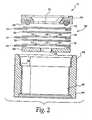
- FIG. 2is a fragmentary exploded view thereof;
- FIG. 3is an elevational view of a measuring electrode component thereof; and
- FIG. 4is an elevational view of a ring electrode therefor.
- a toxic gas sensor systemis generally indicated at 10. Included are a sensor generally indicated at 12 and associated external circuitry equipment comprising a battery 14 and a conventional bias voltage adjustment circuit 16 which apply an impressed voltage between the reference electrode 28 and the measuring electrode 30. An output device 22 monitors the current flow into the sensor 12.' The sensor is employed to measure concentrations of gaseous and liquid target materials, such as ammonia and volatile amines.
- a potentiostat circuitapplies a control voltage between reference electrode 28 and the sensing electrode.
- a sensing or measuring electrode generally indicated at 30is grounded at 32, and is located measuring electrode 30 so as to improve measuring accuracy and response time for the system.
- the sensor 12operates on the amperometric basis.
- the reference electrode 28serves as an electrical reference point which, in combination with an external electronic voltage stabilizing circuit 24 holds the potential of the measuring electrode 30 constant.
- the reference electrode 28employs ruthenium as catalyst, overlaid on a perforated tape substrate, preferably of polytetrafluoroethylene material.
- the ruthenium catalysthas been found to provide an optimal working potential for measuring electrode 30 when employed with the preferred electrolyte 40.
- Sensor 12includes a housing 44 formed of any suitable material resistant to the electrolyte 40.
- housing 44is constructed of ABS plastic or polyester material.
- the internal cavity of housing 44is sealed at the top by an electrode assembly generally indicated at 50. Entrance to the cavity of housing 44 is gained by removing bottom cover , which is hermetically sealed to housing 44 after the electrolyte has been added. Ultrasonic welding or another conventional mode of sealing is contemplated, and it is generally preferred that the resulting construction be liquid-tight.
- the electrolyte 40may include virtually any suitable organic or water based electrolyte compatible with the reagents employed.
- the electrolyteincludes a stable oxidizable metal ion which is Mn 2+ .
- stable oxidizable metal ionrefers to metal ions which remain at a given oxidation state under standard conditions. Metal ions useful in the present invention may be oxidized to a higher oxidation state under the appropriate conditions, such as for example, exposure of the sensor to a target component in the presence of a catalyst, and are effective for providing ionic conductivity.
- the metal ion that is usedis a manganese-ion, which stably exists as Mn +2 and is oxidized to Mn +4 .
- the stable oxidizable metal ionis provided to the electrolyte in the form of a salt.
- the stable oxidizable metal saltsmay be any salt which is soluble in the organic or water based electrolyte and which is effective for providing ionic conductivity.
- the electrolytepreferably comprises a hydrous solution of manganese (II) salt and most preferably, manganese (II) nitrate or manganese (II) sulfate.
- the stable oxidizable metal saltmay be provided in a concentrated form and diluted in water or organic solvent to provide the electrolyte.
- organic solventpropylene carbonate and/or butyrolactone may be used as a solvent for the oxidizable metal salt.
- the reference electrode 28 in combination with the potentiostat 24keeps the potential of the measuring electrode constant by applying an electrical current.
- the measured current indicated by output device 22exhibits a linear dependence to the concentration of the target material, herein ammonia, particularly gaseous ammonia, and volatile amines.
- Volatile amines that can be detected and measured by the present inventioninclude methylamine and tertiary-butylamine.
- the electrode package 50includes a holding ring 58, including an O-ring of VITON or other suitable material, indicated by the reference numeral 62.
- the measuring electrode 30is located underneath the holding ring 58 and is in electrical contact at its bottom surface with a first of three collecting electrode 64.
- a first insulator layer or separator 66is made of suitable dielectric material, and preferably comprises a glass fiber fleece. Separator 66 prevents direct electrical contact between the measuring electrode 30 and the reference electrode 28.
- Reference electrode 28preferably has an annular shape with a central opening 68 identified by reference lines 70, shown for clarity of illustration.
- a second separator 72prevents direct electrical contact between the reference electrode 28 and the lowermost counter electrode 18.
- counter electrode 18has the same general dimensions and shape of annular reference electrode 28. Accordingly, counter electrode 18 includes a central opening 74, the dimensions of which are illustrated by reference lines 76.
- An optional support disk 82provides support for the relatively thin flexible electrode and separator layers disposed thereabove. As can be seen in Fig. 2 , the upper end 76 of housing 44 includes a pocket or recess 78 which receives the support 82.
- the disk-shaped support 82includes a central opening 84 to allow the passage of electrolyte 40 therethrough.
- the measuring electrodeincludes a support layer, preferably a perforated support tape 90, joined in intimate contact with a catalyst layer 92.
- the support layer 90comprises conventional polytetrafluoroethylene tape having a thickness of about 0.1 mm to about 0.5 mm, a pore size of about 20% to about 50%, and having about 0.1 ⁇ to about 1 ⁇ of pore diameter.
- the catalyst layer 92may be formed from a variety of materials, including gold powder, graphite powder or graphite felt and mixtures thereof.
- measuring electrode 30is prepared by mixing a gold powder or a finely dispersed graphite powder with a tetrafluoroethylene dispersion to form a wet mixture which is then applied to the porous support tape 90.
- the catalystpreferably is applied at a rate of 5 to 10 mg/cm 2 .
- the catalyst layeris dried on the polytetrafluoroethylene tape 90 and is thereafter pressed and sintered in order to obtain a strong intimate bond on a microscopic basis, between the tape and catalyst layers.
- gold powder and graphite powderare preferred, other materials can be chosen as a catalyst for the oxidation of manganese (II) to manganese (IV).
- alternative measuring electrode catalystsinclude iridium and ruthenium.
- the reference electrode 28has an overall ring or annular shape with a central aperture 102, and employs a construction similar to that of the measuring electrode 30.
- reference electrode 28comprises a tape support 96, preferably of polytetrafluoroethylene material.
- a catalystpreferably of Ruthenium Black is formed as a wet mixture with tetrafluoroethylene. This mixture is then applied to the perforated tape support 96 and allowed to dry.
- the support layer 96 and catalyst layer 98are pressed together and sintered to form an intimate bond between the two.
- the pressing and the sintering of the reference electrodeis not as critical as for the measuring electrode and may be substituted by other conventional electrode construction techniques.
- the electrolyte 40 within the cavity of housing 44can freely travel in an upward direction so as to contact the underneath surface of measuring electrode 30.
- the electrolytetravels through central opening 84 in disk layer 82 and the separator layers 66, 72 are constructed so as to be readily permeable to the electrolyte. Accordingly, the electrolyte travels through the central openings 74 and 68 of electrodes 18 and 28, passing through the final separator layer 66 so as to come into contact with the counter-reference-or measuring electrode 30.
- the holding ring 58maintains the sandwich or nested construction of the electrode assembly 50 by applying a compressive force thereto, pressing the stack of assorted layers against the recess or pocket surface 78 of housing 44.
- the O-ring 62provides an environmental seal for the end edges of the electrode assembly and further is readily deformable under pressure to prevent damage to the underlying layers as the compressing force is applied, thus greatly reducing the skill and attention needed to construct the sensor 12.
- the holding ring 58may be joined to any suitable structure for bringing the target material, either fluid or gas, in contact with the upper surface of measuring electrode 30.
- the support tape 90 of measuring electrode 30serves several functions which cooperate together for the successful operation of the sensor 12.
- the upper surface of the measuring electrode 30is in contact with the target material.
- the upper surface of electrode 30comprises the support tape 90 shown in Fig. 3 , and this support tape is constructed so as to be permeable to the target gas, allowing its downward passage into contact with the underlying catalyst layer 92.
- the catalyst layer 92is pressed, sintered and otherwise intimately bonded to the support tape 90.
- the perforated support tape 90will, to some extent, function as a collimator, the pathways of which are physically terminated at their lower extent at the point of intimate contact with the catalyst layer 92.
- This constructionis believed to contribute to the desired reactivity of the catalyst and, in addition, provides an optimally short transit length for the target gas.
- An important feature of the present inventionis the diffusion barrier joined to the measuring electrode catalyst to form a unitary intimately bonded construction.
- the diffusion barrierlimits the flow of target gas to the catalyst of the sensing electrode and is preferably located immediately adjacent the catalyst so that all of the target gas reaching the catalyst is allowed to fully react with the electrolyte, causing an increase of OH - -ions, so that the oxidation of Mn 2+ at the measuring electrode catalyst can occur.
- the bottom surface of electrode 30, i.e., the bottom surface of catalytic layer 92(see Fig. 3 ) is in contact with the electrolyte which is allowed to travel from the cavity of housing 44.
- the bottom portion of the catalyst layer 92is penetrated by the electrolyte so as to form a three-phase boundary of the electrolyte, the catalyst, and the target gas, the site of an electrochemical reaction of improved sensitivity and response time.
- the electrochemical reactionin this case is an indirect process where a precursor chemical reaction takes place before a following electrochemical reaction is allowed to occur.
- the electrochemical reaction at the three-phase boundaryresults in a measurement current (indicated by output device 22) which exhibits an improved linear dependence with respect to the concentration of target gas, and an extremely stable zero-noise level in the absence of target gas, even with fluctuating ambient temperatures. Further, the sensor of the present invention has been found to be capable of measuring elevated target gas concentrations over prolonged periods of time.
- the target gasis transported by a diffusion layer of the measuring electrode to the three-phase boundary located at the measuring electrode catalyst layer.
- activity of the catalyst layeran electrochemical oxidation of manganese (II) to manganese (IV) result.
- This oxidation reactionwhere Mn 2+ + 2H 2 O -> MnO 2 + 4H + + 2e is enabled because H ⁇ +> ions represented in the equation are neutralized with OH - ions to form water.
- the senor according to the principles of the present inventionoperates on an amperometric basis in a three electrode mode.
- the preferred reagent introduced into the electrolytecomprises a substance which cannot be oxidized in the absence of ammonia, either through oxygen or through an electrochemical reaction.
- the reagent employed in the present inventionis allowed to oxidize only after an increase of the pH value of the electrolyte in the presence of ammonia.
- the reagentcomprises a manganese (II) salt in an aqueous solution or an organic solvent such as propylene carbonate.
- manganese (II) saltin higher concentrations, preferably as nitrate, sulfate or chloride, suppresses evaporation of water of an aqueous electrolyte, while providing sufficient capacity to measure even elevated levels of ammonia concentrations over long periods of time, during which the manganese (II) will be consumed.
- the measuring electrodecan be formed with a porous layer of carbon felt covered with a porous hydrophobic polytetrafluoroethylene membrane.
- the ammonia or its derivatives being measuredis diffused through the porous membrane to the electrode and is dissolved in the electrolyte (either aqueous or organic) trapped in the measuring electrode catalyst, causing an increase of OH- ions according to the equation NH 3 + H 2 O ⁇ NH 4 + + OH - .
- manganese (II)is allowed to oxidize due to a pH-shift of the electrolyte.
- the manganese (II) saltexhibits a very low pH buffer capacity, further enabling a pH-shift in the presence of ammonia.
- the counter electrode 18acts to balance out the reaction at the measuring electrode 30 by reducing oxygen to water according to the following equation O 2 + 2H 2 O + 4e ⁇ 4OH - .
- a three electrode sensoris employed with the measuring electrode 30 of gold catalyst construction, reference electrode 28 of ruthenium catalyst construction and a counter electrode 18 of graphite layer construction.
- the central gas aperture 94 of holding ring 58(see Fig. 2 ) is constructed with a central diameter of 7 millimeters.
- the electrolytewas formed from a 40% solution of manganese nitrate in water. Approximately 0.5 ml was filled in the cavity of housing 44, leaving a small portion of the cavity unfilled to accommodate any gaseous H 2 O which may be diffused into the sensor should the hydrous electrolyte become diluted by an elevated humidity level in the ambient atmosphere.
- the bottom of housing 44is hermetically sealed with ultrasonic welding of bottom cover 52.
- the housingis constructed of ABS plastic.
- the potential difference between the measuring and reference electrodeswas adjusted to zero, with the zero current measuring less than 50 nA over a waiting period of several minutes.
- the sensorwas then exposed to 100 ppm ammonia in air, with the measuring signal at 22 being increased to 13.5 microamperes within 60 seconds.
- the response timerose to 90% of the final sensitivity in less than 30 seconds.
- the measuring signal at 22fell to the original zero level value within 60 seconds. Injections with 100 ppm ammonia were repeated several times resulting in precise near identical values. Virtually no cross sensitivity was recognized when the sensor was exposed to 300 ppm CO, 1000 ppm H 2 , 1200 ppm methanol or 500 ppm CO 2 .
- the measuring electrodewas comprised of finely dispersed graphite powder, a similar construction being employed for the counter electrode 18.
- the reference electrode 28was the same as in Example 1.
- the electrolyte employedprovides a solution of 20 weight percent manganese (II) sulfate in water. Again, 0.5 milliliter was added to the housing cavity, with the bottom cover 52 thereafter being ultrasonically welded to the ABS housing. A zero current of 85 nA was observed after a few minutes.
- a measuring signal of 15.4 microampereswas observed at output 22 after a waiting period of 60 seconds.
- the output valuedropped to its original level within 60 seconds. The same measuring sensitivity was observed upon repeated cyclic exposures of the sensor.
- Example 2Again a three electrode sensor was employed, with the measuring, reference and counter electrodes remaining the same as in Example 2.
- an electrolyte solutionwas formed of 0.5 ml of 10% manganese (II) nitrate solution in propylene carbonate.
- To form a gel structure of the electrolyte0.1 g of a polymethylmethacrylate powder with a particle size of 150 ⁇ m was added.
- the housing 44 in bottom cover 52was formed of polytherephthalate. A zero current level of 38 nA was observed over a waiting period of 2 hours.
- the measuring signal at-22was observed to be 9.5 microamperes.
- Example 3showed an observable zero current shift attributed to sudden changes in the humidity of the air carrying the ammonia target material.
- the present inventionprovides an improved sensor for the control of ammonia or its derivatives, such as volatile amines in the surrounding air, as well as for the determination of ammonia in liquids.
- the sensorexhibits exceptional selectivity and an extremely stable zero-noise level even with fluctuating ambient temperatures.
- the sensorwill work without bias potential and the reference electrode and its associated external circuitry can be omitted, if desired.
- the sensor according to principles of the present inventionmeasures higher ammonia concentrations over extended periods of time.
- the electrolytecan be gelled using conventional techniques. It is important, however, that the separator layer be readily porous to the gel material.
- the sensor according to the present inventioncan be readily employed to measure ammonia and its derivatives as well as gaseous phases in a liquid environment.
- the only procedures for liquid samplesis to add, for example, NaOH to the sample to increase the pH of this sample to pH of >9. This is necessary to form NH 3 from NH 4 + ions.
- the support layer for the catalystfunction as a diffusion barrier, it is possible to practice the present invention with the diffusion barrier being spaced from the catalyst. It is also possible that several diffusion barriers be employed in conjunction with the catalyst layer, either in intimate bonding therewith or in a spaced part arrangement.
Landscapes
- Chemical & Material Sciences (AREA)
- Life Sciences & Earth Sciences (AREA)
- Health & Medical Sciences (AREA)
- Immunology (AREA)
- Pathology (AREA)
- Physics & Mathematics (AREA)
- Analytical Chemistry (AREA)
- Biochemistry (AREA)
- General Health & Medical Sciences (AREA)
- General Physics & Mathematics (AREA)
- Engineering & Computer Science (AREA)
- Electrochemistry (AREA)
- Chemical Kinetics & Catalysis (AREA)
- Molecular Biology (AREA)
- Combustion & Propulsion (AREA)
- Food Science & Technology (AREA)
- Medicinal Chemistry (AREA)
- Measuring Oxygen Concentration In Cells (AREA)
- Investigating Or Analyzing Non-Biological Materials By The Use Of Chemical Means (AREA)
- Investigating Or Analyzing Materials By The Use Of Fluid Adsorption Or Reactions (AREA)
- Electrolytic Production Of Non-Metals, Compounds, Apparatuses Therefor (AREA)
- Catalysts (AREA)
- Electric Double-Layer Capacitors Or The Like (AREA)
Abstract
Description
- The present invention pertains to a sensor for measuring a target component in gaseous or liquid samples and, in particular, for sensing ammonia.
- Toxic gas sensors are relied upon to an ever increasing extent to safeguard the health and safety of personnel entering a possibly hazardous area. With added attention being directed to worker's safety in confined spaces, there is a need for rapidly identifying gaseous or liquid agents, which (even if not asphyxiating or combustible) are nonetheless toxic, using compact, portable equipment. With an increasing integration of electronics, the ability to obtain an instrument read-out of toxic sensors is becoming simpler. However, there remains a need to provide sensors having improved accuracy and sensitivity to avoid inappropriate conclusions drawn from a sensor's output indication.
- Electrochemical methods are frequently used for analyzing traces of gases. In methods of this kind, the measuring electrode of a galvanic cell is brought into contact with the gas to be examined, producing an electrical current which is proportional to the concentration of the compound to be measured. In the case where reducible gases (for example, oxygen, nitrogen dioxide, ozone or chlorine) is measured, there is a reaction on a measuring electrode which acts as a cathode, while oxidizable gases (for example, hydrogen sulfide, carbon monoxide, hydrogen) react on a measuring electrode acting as an anode.
- Many electrochemical ammonia sensor cells in use today employ the Sevringhaus (potentiometric) Principle (DS-A-2009937). A pH glass electrode is employed as a measuring electrode, and the potentials between the pH electrode and a reference electrode are measured. The difference in potential serves as a measurement signal, related to the presence of ammonia through a pH-shift of the electrolyte according to the reaction NH3 + H2O → NH4+ + OH-. This process suffers drawbacks in that the signal is logarithmically related to the ammonia concentration. Moreover, the time to fix the balance is extremely slow. Further, other gases (e.g., SO2, HCl, CO2) are able to change the pH-value of the electrolyte, falsifying the measurements.
- Other commercially available ammonia sensors (such as those available from Sensoric GmBH & Co., operate on the amperometric principle. Sensors of this type respond to a direct transformation of ammonia passing through a gas-permeable membrane onto a catalytic working measurement electrode, according to the following equation:
NH3 → N2 + 6H+ + 6e - Electrodes in these types of sensors include measure, reference and counter-electrodes in contact with a water-free organic gel electrolyte, cooperating with the electro catalyst to oxidize the ammonia to nitrogen. It is important for direct transformation that the electrolyte be a water-free medium. One example of a highly effective catalyst is platinum black. The reaction causes an electric current that is proportional to the concentration of ammonia in the measuring gas. Unfortunately, the oxidation rate of ammonia to nitrogen is not fast enough at higher concentrations, and intermediate by-products of the oxidation of ammonia causes the measuring electrodes to become partly blocked, resulting in a temporary poisoning of this electrode, with a continuous decline in the measuring signal if the ammonia gas is not withdrawn from the sensor. Furthermore, the selectivity of this sensor is not very high.
- Another type of amperometric measurement procedure is known from
GB 2,225,859 - A similar measuring procedure is known (United States Patent No.
5,234,567 ) which uses a chemical species which reacts with ammonia to form a product which is more electrochemically active than ammonia. The chemical species is one of iodine or Nesslers reagent or a solution of manganese and silver nitrate. The preferred chemical reagent is iodine. The ammonia diffuses into the sensor and dissolves readily in water to product OH<-> (reaction 1), which is necessary for a secondary reaction forming iodine-ions (reaction 2).
NH3 + H2O → NH4+ + OH- (1)
60H- + 3I2 → 5I- + IO3- + 3H2O (2)
2I- → I2 + 2e (3) - The measuring signal results from the reformation of iodine from the iodine-ion (reaction 3). This must occur at an elevated potential of the measuring electrode. A + 300 mV bias potential is required between the reference and measuring electrodes. This requires a long warm up time to stabilize the zero reading of the sensor. Another disadvantage is that a very small side reaction can also form iodine-ions from iodine (reaction 4).
I2 + 3H2O → 5I- + IO3- + 6H+ (4) - This side reaction is temperature dependent with a small increase of temperature substantially increasing the zero current, which again is a big disadvantage.
- European Patent Application
EP 0 496 527 A1 describes an electrochemical gas sensor comprising at least a measuring electrode and a counter electrode. In one particular embodiment, the described sensor is used with an electrolyte containing a solution of manganous and silver nitrates. When this sensor is used for detecting a target gas like ammonia, the oxidation reaction is the oxidation of Mn2+ to yield MnO2. The reduction reaction that balances out the oxidation is a reduction of Ag+ to yield Ag. - An object of the present invention is to provide a sensor for measuring a target component in gaseous or liquid samples, in particular ammonia and volatile amines.
- A further object of the present invention is an ammonia sensor having improved accuracy over its designated operating range.
- Yet another object of the present invention is a sensor which is relatively free of maintenance requirements, and which remains stable over extended periods of time.
- It is an object of the present invention to provide a sensor for ammonia and its derivatives in the above method which does not require a bias potential and which has a stable zero-noise level despite fluctuating ambient temperatures and humidity. It is also an object of the present invention to provide a sensor of this type which is able to measure elevated ammonia concentrations over extended periods of time.
- It is important that the sensor provides relatively rapid determinations of toxic concentrations, and do so simply without requiring complex external equipment.
- These and other objects of the present invention are provided in a sensor for measuring a target component in a gaseous or liquid sample comprising:
- (a) a housing
- (b) an electrolyte being contained in the housing, wherein the electolyte includes an oxidizable metal ion which is Mn2+;
- (c) a measuring electrode in contact with said electrolyte, the measuring electrode including a support layer and a catalyst effective for catalyzing the oxidation of said stable oxidizable metal ion in the presence of said target component; and
- (d) a counter electrode in contact with said electrolyte, wherein the counter electrode when in contact with the electrolyte is effective for reducing oxygen to water.
FIG. 1 shows a schematic view of a sensor according to the principles described herein;FIG. 2 is a fragmentary exploded view thereof;FIG. 3 is an elevational view of a measuring electrode component thereof; andFIG. 4 is an elevational view of a ring electrode therefor.- Referring now to the drawings, and initially to
Fig. 1 , a toxic gas sensor system is generally indicated at 10. Included are a sensor generally indicated at 12 and associated external circuitry equipment comprising abattery 14 and a conventional bias voltage adjustment circuit 16 which apply an impressed voltage between thereference electrode 28 and the measuringelectrode 30. Anoutput device 22 monitors the current flow into thesensor 12.' The sensor is employed to measure concentrations of gaseous and liquid target materials, such as ammonia and volatile amines. - A potentiostat circuit applies a control voltage between
reference electrode 28 and the sensing electrode. A sensing or measuring electrode generally indicated at 30 is grounded at 32, and is located measuringelectrode 30 so as to improve measuring accuracy and response time for the system. - The
sensor 12 operates on the amperometric basis. Thereference electrode 28 serves as an electrical reference point which, in combination with an external electronicvoltage stabilizing circuit 24 holds the potential of the measuringelectrode 30 constant. - Preferably, the
reference electrode 28 employs ruthenium as catalyst, overlaid on a perforated tape substrate, preferably of polytetrafluoroethylene material. The ruthenium catalyst has been found to provide an optimal working potential for measuringelectrode 30 when employed with thepreferred electrolyte 40. - The physical construction of
sensor 12 will now be discussed with additional reference toFig. 2 .Sensor 12 includes ahousing 44 formed of any suitable material resistant to theelectrolyte 40. Preferably,housing 44 is constructed of ABS plastic or polyester material. As will be seen herein, the internal cavity ofhousing 44 is sealed at the top by an electrode assembly generally indicated at 50. Entrance to the cavity ofhousing 44 is gained by removing bottom cover , which is hermetically sealed tohousing 44 after the electrolyte has been added. Ultrasonic welding or another conventional mode of sealing is contemplated, and it is generally preferred that the resulting construction be liquid-tight. - The
electrolyte 40 may include virtually any suitable organic or water based electrolyte compatible with the reagents employed. In this aspect of the invention, the electrolyte includes a stable oxidizable metal ion which is Mn2+. As used herein, the term "stable oxidizable metal ion" refers to metal ions which remain at a given oxidation state under standard conditions. Metal ions useful in the present invention may be oxidized to a higher oxidation state under the appropriate conditions, such as for example, exposure of the sensor to a target component in the presence of a catalyst, and are effective for providing ionic conductivity. The metal ion that is used is a manganese-ion, which stably exists as Mn+2 and is oxidized to Mn+4. - The stable oxidizable metal ion is provided to the electrolyte in the form of a salt. The stable oxidizable metal salts may be any salt which is soluble in the organic or water based electrolyte and which is effective for providing ionic conductivity. The electrolyte preferably comprises a hydrous solution of manganese (II) salt and most preferably, manganese (II) nitrate or manganese (II) sulfate.
- The stable oxidizable metal salt may be provided in a concentrated form and diluted in water or organic solvent to provide the electrolyte. In the case of an organic solvent, propylene carbonate and/or butyrolactone may be used as a solvent for the oxidizable metal salt.
- The
reference electrode 28 in combination with thepotentiostat 24 keeps the potential of the measuring electrode constant by applying an electrical current. The measured current indicated byoutput device 22 exhibits a linear dependence to the concentration of the target material, herein ammonia, particularly gaseous ammonia, and volatile amines. Volatile amines that can be detected and measured by the present invention include methylamine and tertiary-butylamine. Referring again toFig. 2 , theelectrode package 50 includes a holdingring 58, including an O-ring of VITON or other suitable material, indicated by thereference numeral 62. The measuringelectrode 30 is located underneath the holdingring 58 and is in electrical contact at its bottom surface with a first of three collectingelectrode 64. A first insulator layer orseparator 66 is made of suitable dielectric material, and preferably comprises a glass fiber fleece.Separator 66 prevents direct electrical contact between the measuringelectrode 30 and thereference electrode 28. Reference electrode 28 preferably has an annular shape with acentral opening 68 identified byreference lines 70, shown for clarity of illustration. Asecond separator 72 prevents direct electrical contact between thereference electrode 28 and thelowermost counter electrode 18. Preferably,counter electrode 18 has the same general dimensions and shape ofannular reference electrode 28. Accordingly,counter electrode 18 includes acentral opening 74, the dimensions of which are illustrated byreference lines 76. Anoptional support disk 82 provides support for the relatively thin flexible electrode and separator layers disposed thereabove. As can be seen inFig. 2 , theupper end 76 ofhousing 44 includes a pocket orrecess 78 which receives thesupport 82. The disk-shapedsupport 82 includes acentral opening 84 to allow the passage ofelectrolyte 40 therethrough.- With additional reference to
Fig. 3 , the measuring electrode includes a support layer, preferably aperforated support tape 90, joined in intimate contact with acatalyst layer 92. Preferably, thesupport layer 90 comprises conventional polytetrafluoroethylene tape having a thickness of about 0.1 mm to about 0.5 mm, a pore size of about 20% to about 50%, and having about 0.1µ to about 1µ of pore diameter. Thecatalyst layer 92 may be formed from a variety of materials, including gold powder, graphite powder or graphite felt and mixtures thereof. Preferably, measuringelectrode 30 is prepared by mixing a gold powder or a finely dispersed graphite powder with a tetrafluoroethylene dispersion to form a wet mixture which is then applied to theporous support tape 90. The catalyst preferably is applied at a rate of 5 to 10 mg/cm2. - The catalyst layer is dried on the
polytetrafluoroethylene tape 90 and is thereafter pressed and sintered in order to obtain a strong intimate bond on a microscopic basis, between the tape and catalyst layers. While gold powder and graphite powder are preferred, other materials can be chosen as a catalyst for the oxidation of manganese (II) to manganese (IV). Examples of alternative measuring electrode catalysts include iridium and ruthenium. - As will be appreciated from the above, an inexpensive construction of the
sensor 12 is possible. As a further advantage, no special additional treatment, such as activation of the catalyst layer or the porous support has been found to be necessary. - Referring now to
Fig. 4 , thereference electrode 28 has an overall ring or annular shape with acentral aperture 102, and employs a construction similar to that of the measuringelectrode 30. Preferably,reference electrode 28 comprises atape support 96, preferably of polytetrafluoroethylene material. A catalyst, preferably of Ruthenium Black is formed as a wet mixture with tetrafluoroethylene. This mixture is then applied to theperforated tape support 96 and allowed to dry. Preferably, thesupport layer 96 andcatalyst layer 98 are pressed together and sintered to form an intimate bond between the two. The pressing and the sintering of the reference electrode is not as critical as for the measuring electrode and may be substituted by other conventional electrode construction techniques. - Referring again to
Fig. 2 , it can be seen that theelectrolyte 40 within the cavity ofhousing 44 can freely travel in an upward direction so as to contact the underneath surface of measuringelectrode 30. The electrolyte travels throughcentral opening 84 indisk layer 82 and the separator layers 66, 72 are constructed so as to be readily permeable to the electrolyte. Accordingly, the electrolyte travels through thecentral openings electrodes final separator layer 66 so as to come into contact with the counter-reference-or measuringelectrode 30. - The holding
ring 58 maintains the sandwich or nested construction of theelectrode assembly 50 by applying a compressive force thereto, pressing the stack of assorted layers against the recess orpocket surface 78 ofhousing 44. The O-ring 62 provides an environmental seal for the end edges of the electrode assembly and further is readily deformable under pressure to prevent damage to the underlying layers as the compressing force is applied, thus greatly reducing the skill and attention needed to construct thesensor 12. - The holding
ring 58 may be joined to any suitable structure for bringing the target material, either fluid or gas, in contact with the upper surface of measuringelectrode 30. With reference toFigs. 2 and3 , thesupport tape 90 of measuringelectrode 30 serves several functions which cooperate together for the successful operation of thesensor 12. As mentioned, the upper surface of the measuringelectrode 30 is in contact with the target material. Preferably, the upper surface ofelectrode 30 comprises thesupport tape 90 shown inFig. 3 , and this support tape is constructed so as to be permeable to the target gas, allowing its downward passage into contact with theunderlying catalyst layer 92. Preferably, as mentioned, thecatalyst layer 92 is pressed, sintered and otherwise intimately bonded to thesupport tape 90. Theperforated support tape 90 will, to some extent, function as a collimator, the pathways of which are physically terminated at their lower extent at the point of intimate contact with thecatalyst layer 92. This construction is believed to contribute to the desired reactivity of the catalyst and, in addition, provides an optimally short transit length for the target gas. An important feature of the present invention is the diffusion barrier joined to the measuring electrode catalyst to form a unitary intimately bonded construction. The diffusion barrier limits the flow of target gas to the catalyst of the sensing electrode and is preferably located immediately adjacent the catalyst so that all of the target gas reaching the catalyst is allowed to fully react with the electrolyte, causing an increase of OH--ions, so that the oxidation of Mn2+ at the measuring electrode catalyst can occur. These features are, in part, believed to be important for the relationship between the output current signal of the sensor and the partial pressure of the target gas. - Further, as mentioned, the bottom surface of
electrode 30, i.e., the bottom surface of catalytic layer 92 (seeFig. 3 ) is in contact with the electrolyte which is allowed to travel from the cavity ofhousing 44. As a result, the bottom portion of thecatalyst layer 92 is penetrated by the electrolyte so as to form a three-phase boundary of the electrolyte, the catalyst, and the target gas, the site of an electrochemical reaction of improved sensitivity and response time. The electrochemical reaction in this case is an indirect process where a precursor chemical reaction takes place before a following electrochemical reaction is allowed to occur. - The electrochemical reaction at the three-phase boundary results in a measurement current (indicated by output device 22) which exhibits an improved linear dependence with respect to the concentration of target gas, and an extremely stable zero-noise level in the absence of target gas, even with fluctuating ambient temperatures. Further, the sensor of the present invention has been found to be capable of measuring elevated target gas concentrations over prolonged periods of time.
- As mentioned, the target gas is transported by a diffusion layer of the measuring electrode to the three-phase boundary located at the measuring electrode catalyst layer. This results in an immediate increase of OH- concentration according to the formula NH3 + H2O → NH4+ + OH-. With activity of the catalyst layer, an electrochemical oxidation of manganese (II) to manganese (IV) result. This oxidation reaction, where Mn2+ + 2H2O -> MnO2 + 4H+ + 2e is enabled because H<+> ions represented in the equation are neutralized with OH- ions to form water. As a result, commercial sensors constructed according to principles of the present invention have been found to exhibit improved performance, delivering a linear signal for ammonia concentrations ranging between 0 and 100 ppm, with the reaction time to ammonia taking between 30 and 60 seconds. Typically, commercial sensors deliver an output signal of 80 to 160 nA/ppm.
- As set out above, the sensor according to the principles of the present invention operates on an amperometric basis in a three electrode mode. The preferred reagent introduced into the electrolyte comprises a substance which cannot be oxidized in the absence of ammonia, either through oxygen or through an electrochemical reaction. The reagent employed in the present invention is allowed to oxidize only after an increase of the pH value of the electrolyte in the presence of ammonia. As mentioned, the reagent comprises a manganese (II) salt in an aqueous solution or an organic solvent such as propylene carbonate. As a result, the electrochemical reaction occurs at a faster rate than the chemical oxidation of manganese (II) salt with oxygen present in the air. The use of manganese (II) salt in higher concentrations, preferably as nitrate, sulfate or chloride, suppresses evaporation of water of an aqueous electrolyte, while providing sufficient capacity to measure even elevated levels of ammonia concentrations over long periods of time, during which the manganese (II) will be consumed.
- The measuring electrode can be formed with a porous layer of carbon felt covered with a porous hydrophobic polytetrafluoroethylene membrane. The ammonia or its derivatives being measured is diffused through the porous membrane to the electrode and is dissolved in the electrolyte (either aqueous or organic) trapped in the measuring electrode catalyst, causing an increase of OH- ions according to the equation NH3 + H2O → NH4+ + OH-. As determined byAllen J. Baro, of Marcel Dekker, Inc. in an article entitled "Standard Potential In Aqueous Solution", the pH dependence of the standard potential for the oxidation of manganese (II) salt is given by the equation
Mn2+ + 2H2O -> MnO2 + 4H+ + 2e (E0 = 1.23 V). - With a pH-shift, a potential shift in a more negative direction occurs with an immediate electrochemical oxidation to manganese (IV) occurring at the porous measuring electrode. A theoretical, much slower oxidation of manganese (II) through oxygen of the air can occur, if at all, only on an insignificant level. The potential for the measuring electrode is fixed by the reference electrode which preferably contains a thinly distributed layer of novel metal catalysts. It is unlikely that mangan-hexamin [Mn(NH3)6]++ complex salt will be formed because the affinity of ammonia to water is greater than the affinity of ammonia to manganese (II) ion and only traces of ammonia ion are present in the electrolyte. Because the formation of [Mn(NH3)6]++ ions requires very high NH4- ion concentrations, manganese (II) is allowed to oxidize due to a pH-shift of the electrolyte. Advantageously, the manganese (II) salt exhibits a very low pH buffer capacity, further enabling a pH-shift in the presence of ammonia.
- At the other end of the electrode stack, the
counter electrode 18 acts to balance out the reaction at the measuringelectrode 30 by reducing oxygen to water according to the following equation
O2 + 2H2O + 4e → 4OH-. - Further advantages of the present invention will become apparent from consideration of the following examples.
- In a first example, a three electrode sensor is employed with the measuring
electrode 30 of gold catalyst construction,reference electrode 28 of ruthenium catalyst construction and acounter electrode 18 of graphite layer construction. Thecentral gas aperture 94 of holding ring 58 (seeFig. 2 ) is constructed with a central diameter of 7 millimeters. The electrolyte was formed from a 40% solution of manganese nitrate in water. Approximately 0.5 ml was filled in the cavity ofhousing 44, leaving a small portion of the cavity unfilled to accommodate any gaseous H2O which may be diffused into the sensor should the hydrous electrolyte become diluted by an elevated humidity level in the ambient atmosphere. After filling with the electrolyte, the bottom ofhousing 44 is hermetically sealed with ultrasonic welding of bottom cover 52. The housing is constructed of ABS plastic. The potential difference between the measuring and reference electrodes was adjusted to zero, with the zero current measuring less than 50 nA over a waiting period of several minutes. The sensor was then exposed to 100 ppm ammonia in air, with the measuring signal at 22 being increased to 13.5 microamperes within 60 seconds. The response time rose to 90% of the final sensitivity in less than 30 seconds. As soon as the sensor was exposed to fresh air, the measuring signal at 22 fell to the original zero level value within 60 seconds. Injections with 100 ppm ammonia were repeated several times resulting in precise near identical values. Virtually no cross sensitivity was recognized when the sensor was exposed to 300 ppm CO, 1000 ppm H2, 1200 ppm methanol or 500 ppm CO2. - In a second example, the measuring electrode was comprised of finely dispersed graphite powder, a similar construction being employed for the
counter electrode 18. Thereference electrode 28 was the same as in Example 1. The electrolyte employed provides a solution of 20 weight percent manganese (II) sulfate in water. Again, 0.5 milliliter was added to the housing cavity, with the bottom cover 52 thereafter being ultrasonically welded to the ABS housing. A zero current of 85 nA was observed after a few minutes. Upon exposing the sensor to 100 ppm ammonia in air, a measuring signal of 15.4 microamperes was observed atoutput 22 after a waiting period of 60 seconds. Upon removal of the ammonia/air mixture and exposing the sensor to fresh air, the output value dropped to its original level within 60 seconds. The same measuring sensitivity was observed upon repeated cyclic exposures of the sensor. - Again a three electrode sensor was employed, with the measuring, reference and counter electrodes remaining the same as in Example 2. In the third example an electrolyte solution was formed of 0.5 ml of 10% manganese (II) nitrate solution in propylene carbonate. To form a gel structure of the electrolyte 0.1 g of a polymethylmethacrylate powder with a particle size of 150 µm was added. The
housing 44 in bottom cover 52 was formed of polytherephthalate. A zero current level of 38 nA was observed over a waiting period of 2 hours. Upon exposure of the sensor to a gas sample comprising 100 ppm ammonia in air, the measuring signal at-22 was observed to be 9.5 microamperes. Upon repeated tests, the sensor of - Example 3 showed an observable zero current shift attributed to sudden changes in the humidity of the air carrying the ammonia target material.
- As can be seen from the above, the present invention provides an improved sensor for the control of ammonia or its derivatives, such as volatile amines in the surrounding air, as well as for the determination of ammonia in liquids. The sensor exhibits exceptional selectivity and an extremely stable zero-noise level even with fluctuating ambient temperatures. In addition, the sensor will work without bias potential and the reference electrode and its associated external circuitry can be omitted, if desired. In addition, the the sensor according to principles of the present invention measures higher ammonia concentrations over extended periods of time.
- Certain variations are possible. For example, the electrolyte can be gelled using conventional techniques. It is important, however, that the separator layer be readily porous to the gel material.
- Further, although examples of operation are given for air sensors, the sensor according to the present invention can be readily employed to measure ammonia and its derivatives as well as gaseous phases in a liquid environment. The only procedures for liquid samples is to add, for example, NaOH to the sample to increase the pH of this sample to pH of >9. This is necessary to form NH3 from NH4+ ions. Further, although it is preferred that the support layer for the catalyst function as a diffusion barrier, it is possible to practice the present invention with the diffusion barrier being spaced from the catalyst. It is also possible that several diffusion barriers be employed in conjunction with the catalyst layer, either in intimate bonding therewith or in a spaced part arrangement.
- The drawings and the foregoing descriptions are not intended to represent the only forms of the invention in regard to the details of its construction and manner of operation. Changes in form and in the proportion of parts, as well as the substitution of equivalents, are contemplated as circumstances may suggest or render expedient; and although specific terms have been employed, they are intended in a generic and descriptive sense only and not for the purposes of limitation, the scope of the invention being delineated by the following claims.
Claims (12)
- A sensor for measuring a target component in gaseous or aqueous samples, the sensor comprising:a) a housing (44),b) an electrolyte (40) being contained in the housing (44), wherein the electrolyte (40) includes an oxidizable metal ion, which is Mn2+c) a measuring electrode(30) including a support layer (90) and a catalyst (92) effective for catalyzing the oxidation of said stable oxidizable metal ion in the presence of said target component in contact with the electrolyte (40), andd) a counter electrode (18) in contact with the electrolyte (40), wherein the counter electrode (18) when in contact with the electrolyte (40) is effective for reducing oxygen to water.
- The sensor according to claim 1, wherein the electrolyte (40) comprises water.
- The sensor according to any one of claim 1 or 2, wherein the electrolyte (40) comprises an organic solvent.
- The sensor according to claim 3, wherein the organic solvent is selected from the group consisting of propylene carbonate, butyrolactone and mixtures thereof.
- The sensor according to claim 3 or claim 4, wherein the electrolyte (40) further comprises polymethylmethacrylate.
- The sensor according to claim 5, wherein the electrolyte (40) is immobilized in the form of a gel.
- The sensor according to any one of claims 1-6, wherein the sensor is effective for catalyzing the oxidation of Mn2+ to Mn4+.
- The sensor according to any one of claims 1-7, wherein the oxidizable manganese ion is provided as a salt selected from the group consisting of manganese (II) nitrate, manganese (II) sulfate, manganese (II) chloride and mixtures thereon.
- The sensor according to any one of claims 1-8, wherein the target component is ammonia or a volatile amine.
- The sensor according to any one of claims 9 and 10, wherein the sensor further comprises a reference electrode (28).
- The sensor according to claim 10, wherein the reference electrode (28) contains a mixture of ruthenium powder and a hydrophobic binder.
- Use of a sensor according to any one of claims 1-11 in an electrochemical detector for measuring a target component in a gaseous or liquid sample.
Applications Claiming Priority (2)
| Application Number | Priority Date | Filing Date | Title |
|---|---|---|---|
| US09/310,431US6248224B1 (en) | 1999-05-12 | 1999-05-12 | Toxic sensor and method of manufacture |
| EP00937538AEP1183528B1 (en) | 1999-05-12 | 2000-05-12 | Electrochemical sensor for ammonia and volatile amines |
Related Parent Applications (2)
| Application Number | Title | Priority Date | Filing Date |
|---|---|---|---|
| EP00937538.7Division | 2000-05-12 | ||
| EP00937538ADivisionEP1183528B1 (en) | 1999-05-12 | 2000-05-12 | Electrochemical sensor for ammonia and volatile amines |
Publications (2)
| Publication Number | Publication Date |
|---|---|
| EP2278321A1 EP2278321A1 (en) | 2011-01-26 |
| EP2278321B1true EP2278321B1 (en) | 2015-06-17 |
Family
ID=23202463
Family Applications (3)
| Application Number | Title | Priority Date | Filing Date |
|---|---|---|---|
| EP10184094.0AExpired - LifetimeEP2278322B1 (en) | 1999-05-12 | 2000-05-12 | A method for measuring a target component in gaseous or liquid samples |
| EP00937538AExpired - LifetimeEP1183528B1 (en) | 1999-05-12 | 2000-05-12 | Electrochemical sensor for ammonia and volatile amines |
| EP10184013.0AExpired - LifetimeEP2278321B1 (en) | 1999-05-12 | 2000-05-12 | A sensor for measuring a target component in gaseous or liquid samples |
Family Applications Before (2)
| Application Number | Title | Priority Date | Filing Date |
|---|---|---|---|
| EP10184094.0AExpired - LifetimeEP2278322B1 (en) | 1999-05-12 | 2000-05-12 | A method for measuring a target component in gaseous or liquid samples |
| EP00937538AExpired - LifetimeEP1183528B1 (en) | 1999-05-12 | 2000-05-12 | Electrochemical sensor for ammonia and volatile amines |
Country Status (13)
| Country | Link |
|---|---|
| US (1) | US6248224B1 (en) |
| EP (3) | EP2278322B1 (en) |
| JP (1) | JP2002544478A (en) |
| KR (1) | KR20020011410A (en) |
| CN (1) | CN1350640A (en) |
| AT (1) | ATE491937T1 (en) |
| AU (1) | AU5269000A (en) |
| CY (1) | CY1112742T1 (en) |
| DE (1) | DE60045372D1 (en) |
| DK (1) | DK1183528T3 (en) |
| ES (1) | ES2358185T3 (en) |
| PT (1) | PT1183528E (en) |
| WO (1) | WO2000068676A1 (en) |
Families Citing this family (35)
| Publication number | Priority date | Publication date | Assignee | Title |
|---|---|---|---|---|
| AT409798B (en)* | 1998-11-19 | 2002-11-25 | Hoffmann La Roche | ELECTRODE SYSTEM |
| US6428684B1 (en)* | 2000-08-02 | 2002-08-06 | Industrial Scientific Corporation | Method and apparatus for diagnosing the condition of a gas sensor |
| DE10102237A1 (en)* | 2001-01-19 | 2002-08-08 | Bosch Gmbh Robert | Device for dosing a urea solution |
| US7790006B2 (en)* | 2002-05-03 | 2010-09-07 | Rosemount Analytical Inc. | Free chlorine sensor |
| DE10245337B4 (en)* | 2002-09-27 | 2018-12-20 | Robert Bosch Gmbh | Electrochemical sensor with ionic liquids as electrolyte |
| US7140229B2 (en) | 2004-06-29 | 2006-11-28 | Mst Technology Gmbh | Gas-monitoring assembly comprising one or more gas sensors and one or more getters, and method of using same |
| US20090065370A1 (en)* | 2004-12-28 | 2009-03-12 | Nair Balakrishnan G | Ammonia gas sensor method and device |
| US7442555B2 (en)* | 2004-12-28 | 2008-10-28 | Nair Balakrishnan G | Ammonia gas sensor method and device |
| WO2006074541A1 (en)* | 2005-01-14 | 2006-07-20 | Sensific Technologies Inc. | Redox-active species sensor and method of use thereof |
| DE102005003050B3 (en)* | 2005-01-22 | 2006-06-29 | Dräger Safety AG & Co. KGaA | Gas sensor, for use e.g. in chemical or petroleum plants, including porous, gas-permeable, water-impermeable cap for protection against harsh environments, fittable with calibration gas supplying adapter |
| KR100738088B1 (en)* | 2005-12-28 | 2007-07-12 | 삼성전자주식회사 | Method for detecting presence of toxic substance in sample and apparatus therefor |
| US7774038B2 (en) | 2005-12-30 | 2010-08-10 | Medtronic Minimed, Inc. | Real-time self-calibrating sensor system and method |
| EP2035824A2 (en)* | 2006-06-14 | 2009-03-18 | Ceramatec, Inc. | Ammonia gas sensor with dissimilar electrodes |
| WO2008129801A1 (en)* | 2007-03-29 | 2008-10-30 | Nec Corporation | Measurement device |
| DE102008044238A1 (en) | 2008-12-01 | 2010-06-10 | Msa Auer Gmbh | Electrochemical gas sensor used for detecting or measuring chlorine, fluorine, bromine, oxygen or chlorine dioxide, comprises ionic liquid as electrolyte, where ionic liquid comprises organic, organometallic and/or inorganic additives |
| JP5432276B2 (en) | 2008-12-01 | 2014-03-05 | エムエスアー アオアー ゲーエムベーハー | Electrochemical gas sensor with ionic liquid electrolyte |
| KR101105335B1 (en)* | 2009-07-27 | 2012-01-16 | 한국과학기술원 | Method for manufacturing hydrogen electrochemical sensor using tetramethylammonium hydroxide pentahydrate |
| WO2016043848A2 (en)* | 2014-07-24 | 2016-03-24 | Spec Sensors, Llc | Electrochemical sensors and packaging and related methods |
| US10761046B2 (en) | 2010-11-24 | 2020-09-01 | Sensirion Ag | Electrochemical sensors and packaging and related methods |
| FR2969295B1 (en)* | 2010-12-16 | 2012-12-14 | Commissariat Energie Atomique | MULTIFUNCTIONAL DETECTOR OF GASEOUS COMPOUNDS AND APPLICATIONS THEREOF |
| US9097661B2 (en) | 2011-01-27 | 2015-08-04 | Caterpillar, Inc. | Electrochemical sulfur sensor and the method of making the same |
| DE102011087592A1 (en) | 2011-12-01 | 2013-06-06 | Msa Auer Gmbh | Electrochemical gas sensor, useful to detect e.g. ammonia, comprises electrolyte comprising ionic liquid that includes protic ammonium cation with dissociable hydrogen atom, and two electrodes present in electrical contact with electrolyte |
| DE102011085174A1 (en) | 2011-10-25 | 2013-04-25 | Msa Auer Gmbh | Electrochemical gas sensor, useful for detecting ammonia and/or amines, comprises an ionic liquid as electrolyte, where the ionic liquid comprises a protic ammonium cation with a hydrogen atom and consists of di-substituted ammonium cation |
| AU2012330453B2 (en) | 2011-10-25 | 2015-08-06 | Msa Europe Gmbh | Electrochemical gas sensor with an ionic liquid as electrolyte for the detection of ammonia and amines |
| CN103424456B (en)* | 2013-07-23 | 2018-08-10 | 华瑞科学仪器(上海)有限公司 | A kind of three-electrode electrochemical sensor |
| CA2937375A1 (en) | 2014-02-11 | 2015-08-20 | The Board Of Trustees Of The Leland Stanford Junior University | Rapid small volume detection of blood ammonia |
| DE102014002502B4 (en)* | 2014-02-21 | 2021-08-05 | Dräger Safety AG & Co. KGaA | Electrochemical gas sensor and use of an electrochemical gas sensor |
| GB2525393A (en)* | 2014-04-22 | 2015-10-28 | Sprue Safety Products Ltd | Electrochemical cell |
| WO2017014851A1 (en) | 2015-07-22 | 2017-01-26 | Honeywell International Inc. | One piece shaped planar separator |
| WO2017019549A1 (en)* | 2015-07-24 | 2017-02-02 | Spec Sensors, Llc | Electrochemical sensors and packaging and related methods |
| CN105018909B (en)* | 2015-07-31 | 2018-08-21 | 中国科学院烟台海岸带研究所 | It is a kind of using carbon-based material as the metal nano material of template and its synthetic method |
| CN108139352B (en) | 2015-08-24 | 2020-07-24 | 霍尼韦尔国际公司 | Oxygen sensor and method for detecting oxygen |
| CN108139351A (en)* | 2015-10-09 | 2018-06-08 | 哈希公司 | Water quality quantity sensor based on film |
| GB2581779A (en)* | 2019-02-21 | 2020-09-02 | Sensocure As | Sensor |
| CN110208353A (en)* | 2019-06-28 | 2019-09-06 | 北京海益同展信息科技有限公司 | Gas-detecting device and movable termination |
Citations (1)
| Publication number | Priority date | Publication date | Assignee | Title |
|---|---|---|---|---|
| EP0298570A2 (en)* | 1987-07-10 | 1989-01-11 | Bacharach, Inc. | Compact electrochemical cell for gas detection |
Family Cites Families (18)
| Publication number | Priority date | Publication date | Assignee | Title |
|---|---|---|---|---|
| US3743589A (en) | 1971-12-23 | 1973-07-03 | Honeywell Inc | Electrochemical vapor detector |
| DE2436261B2 (en)* | 1974-07-27 | 1976-11-25 | Bayer Ag, 5090 Leverkusen | ELECTROCHEMICAL GAS DETECTORS |
| DE2621676C3 (en)* | 1976-05-15 | 1979-01-11 | Bayer Ag, 5090 Leverkusen | Electrochemical gas detector for the detection of gas traces |
| US4105525A (en) | 1978-01-23 | 1978-08-08 | Orion Research Incorporated | Internal standard electrolyte for ammonia sensor |
| US4297173A (en) | 1980-05-22 | 1981-10-27 | Ajinomoto Company, Incorporated | Method for determining ammonia and sensor therefor |
| US4302315A (en)* | 1980-06-18 | 1981-11-24 | Becton, Dickinson And Company | Gas sensing unit |
| DE3033796A1 (en)* | 1980-09-09 | 1982-04-22 | Bayer Ag, 5090 Leverkusen | ELECTROCHEMICAL SENSOR FOR DETECTING REDUCING GASES, ESPECIALLY CARBON MONOXIDE, HYDRAZINE AND HYDROGEN IN AIR |
| US4700709A (en) | 1986-01-30 | 1987-10-20 | Cornell Research Foundation, Inc. | Apparatus and method for determining ammonium ion concentration and total ammonia concentration in fluids or tissue |
| US4851088A (en)* | 1987-03-05 | 1989-07-25 | Honeywell Inc. | Electrochemical detection of carbon dioxide |
| DE3841622A1 (en) | 1988-12-10 | 1990-06-13 | Draegerwerk Ag | ELECTROCHEMICAL MEASURING CELL FOR THE AMPEROMETRIC DETERMINATION OF AMMONIA AND ITS DERIVATIVES |
| US5198092A (en)* | 1989-04-29 | 1993-03-30 | Dragerwerk Aktiengesellschaft | Electrochemical measuring cell for determining ammonia or hydrazine in a measuring sample |
| EP0398286A3 (en) | 1989-05-18 | 1991-09-25 | Nisshinbo Industries, Inc. | Ammonia sensor |
| DE3923717A1 (en)* | 1989-07-18 | 1991-01-24 | Draegerwerk Ag | ELECTROCHEMICAL MEASURING CELL FOR DETECTING BLUE ACID OR SULFUR DIOXIDE |
| GB9101643D0 (en) | 1991-01-25 | 1991-03-06 | City Tech | Gas sensor |
| DE4137030A1 (en) | 1991-11-11 | 1993-05-13 | Mst Micro Sensor Tech Gmbh | ELECTROCHEMICAL SENSOR FOR MEASURING THE GAS CONCENTRATION |
| FI94179C (en) | 1993-03-03 | 1995-07-25 | Kone Oy | Method and apparatus for determining the ammonia content and method for manufacturing the detector |
| CH686981A5 (en)* | 1994-02-09 | 1996-08-15 | Christian Dr Huggenberger | Ammonia sensor. |
| US5690808A (en)* | 1996-01-25 | 1997-11-25 | Teledyne Industries, Inc. | Electrochemical gas sensors and methods for sensing electrochemical active gases in gas mixtures |
- 1999
- 1999-05-12USUS09/310,431patent/US6248224B1/ennot_activeExpired - Lifetime
- 2000
- 2000-05-12AUAU52690/00Apatent/AU5269000A/ennot_activeAbandoned
- 2000-05-12EPEP10184094.0Apatent/EP2278322B1/ennot_activeExpired - Lifetime
- 2000-05-12WOPCT/US2000/013002patent/WO2000068676A1/ennot_activeApplication Discontinuation
- 2000-05-12KRKR1020017014399Apatent/KR20020011410A/ennot_activeWithdrawn
- 2000-05-12DEDE60045372Tpatent/DE60045372D1/ennot_activeExpired - Lifetime
- 2000-05-12PTPT00937538Tpatent/PT1183528E/enunknown
- 2000-05-12ATAT00937538Tpatent/ATE491937T1/enactive
- 2000-05-12CNCN00807444Apatent/CN1350640A/enactivePending
- 2000-05-12JPJP2000616410Apatent/JP2002544478A/ennot_activeWithdrawn
- 2000-05-12EPEP00937538Apatent/EP1183528B1/ennot_activeExpired - Lifetime
- 2000-05-12EPEP10184013.0Apatent/EP2278321B1/ennot_activeExpired - Lifetime
- 2000-05-12ESES00937538Tpatent/ES2358185T3/ennot_activeExpired - Lifetime
- 2000-05-12DKDK00937538.7Tpatent/DK1183528T3/enactive
- 2011
- 2011-03-11CYCY20111100281Tpatent/CY1112742T1/enunknown
Patent Citations (1)
| Publication number | Priority date | Publication date | Assignee | Title |
|---|---|---|---|---|
| EP0298570A2 (en)* | 1987-07-10 | 1989-01-11 | Bacharach, Inc. | Compact electrochemical cell for gas detection |
Also Published As
| Publication number | Publication date |
|---|---|
| WO2000068676A1 (en) | 2000-11-16 |
| AU5269000A (en) | 2000-11-21 |
| DE60045372D1 (en) | 2011-01-27 |
| JP2002544478A (en) | 2002-12-24 |
| KR20020011410A (en) | 2002-02-08 |
| EP1183528A4 (en) | 2003-04-02 |
| CN1350640A (en) | 2002-05-22 |
| PT1183528E (en) | 2011-03-21 |
| EP2278322B1 (en) | 2015-06-17 |
| US6248224B1 (en) | 2001-06-19 |
| DK1183528T3 (en) | 2011-04-04 |
| EP1183528B1 (en) | 2010-12-15 |
| EP2278321A1 (en) | 2011-01-26 |
| ES2358185T3 (en) | 2011-05-06 |
| CY1112742T1 (en) | 2016-02-10 |
| ATE491937T1 (en) | 2011-01-15 |
| EP1183528A1 (en) | 2002-03-06 |
| EP2278322A1 (en) | 2011-01-26 |
Similar Documents
| Publication | Publication Date | Title |
|---|---|---|
| EP2278321B1 (en) | A sensor for measuring a target component in gaseous or liquid samples | |
| JP3851561B2 (en) | Film-type solid polymer ionomer sensor and sensor cell | |
| US4474648A (en) | Gas sensor | |
| US4132616A (en) | Gas sensor | |
| US5071526A (en) | Acidic gas sensors and method of using same | |
| JPH0656376B2 (en) | Electrochemical gas sensor | |
| US7179355B2 (en) | Electrochemical cell | |
| EP1212610B1 (en) | Carbon monoxide sensor | |
| US6001240A (en) | Electrochemical detection of hydrogen cyanide | |
| US4302315A (en) | Gas sensing unit | |
| US6808618B2 (en) | Chemical sensing apparatus and methods | |
| EP1332358A1 (en) | Acid gas measuring sensors and method of making same | |
| US3878080A (en) | Carbon monoxide sensor | |
| US6251244B1 (en) | Electrochemical measuring cell for detecting hydride gases | |
| US4333810A (en) | Analyzer for chemical oxidizing or reducing agents | |
| US4713164A (en) | Apparatus for analyzing malodors in the breath | |
| US4797180A (en) | Method for the detection of noxious gases | |
| GB2075197A (en) | Electrochemical gas sensor | |
| US20060249385A1 (en) | Chemical sensing apparatus | |
| GB2073430A (en) | Gas detection device | |
| JP3307827B2 (en) | Potentiometric electrolytic ammonia gas detector | |
| GB2288874A (en) | Reducing gas analysis apparatus | |
| Gas | Amperometric gas sensors | |
| Leonova | Principles of functioning and state-of-the-art of low-temperature potentiometric hydrogen sensors based on solid electrolytes | |
| Hobbs | 1.2 Electrochemical Sensors |
Legal Events
| Date | Code | Title | Description |
|---|---|---|---|
| PUAI | Public reference made under article 153(3) epc to a published international application that has entered the european phase | Free format text:ORIGINAL CODE: 0009012 | |
| 17P | Request for examination filed | Effective date:20100930 | |
| AC | Divisional application: reference to earlier application | Ref document number:1183528 Country of ref document:EP Kind code of ref document:P | |
| AK | Designated contracting states | Kind code of ref document:A1 Designated state(s):AT BE CH CY DE DK ES FI FR GB GR IE IT LI LU MC NL PT SE | |
| 17Q | First examination report despatched | Effective date:20120323 | |
| RAP1 | Party data changed (applicant data changed or rights of an application transferred) | Owner name:LIFE SAFETY GERMANY GMBH | |
| RIC1 | Information provided on ipc code assigned before grant | Ipc:G01N 33/00 20060101ALI20141113BHEP Ipc:G01N 27/404 20060101ALI20141113BHEP Ipc:G01N 27/49 20060101AFI20141113BHEP | |
| GRAP | Despatch of communication of intention to grant a patent | Free format text:ORIGINAL CODE: EPIDOSNIGR1 | |
| INTG | Intention to grant announced | Effective date:20150108 | |
| GRAS | Grant fee paid | Free format text:ORIGINAL CODE: EPIDOSNIGR3 | |
| GRAA | (expected) grant | Free format text:ORIGINAL CODE: 0009210 | |
| AC | Divisional application: reference to earlier application | Ref document number:1183528 Country of ref document:EP Kind code of ref document:P | |
| AK | Designated contracting states | Kind code of ref document:B1 Designated state(s):AT BE CH CY DE DK ES FI FR GB GR IE IT LI LU MC NL PT SE | |
| REG | Reference to a national code | Ref country code:GB Ref legal event code:FG4D | |
| REG | Reference to a national code | Ref country code:CH Ref legal event code:NV Representative=s name:BOHEST AG, CH Ref country code:CH Ref legal event code:EP | |
| REG | Reference to a national code | Ref country code:AT Ref legal event code:REF Ref document number:732198 Country of ref document:AT Kind code of ref document:T Effective date:20150715 | |
| REG | Reference to a national code | Ref country code:DE Ref legal event code:R096 Ref document number:60048984 Country of ref document:DE | |
| REG | Reference to a national code | Ref country code:IE Ref legal event code:FG4D | |
| PG25 | Lapsed in a contracting state [announced via postgrant information from national office to epo] | Ref country code:FI Free format text:LAPSE BECAUSE OF FAILURE TO SUBMIT A TRANSLATION OF THE DESCRIPTION OR TO PAY THE FEE WITHIN THE PRESCRIBED TIME-LIMIT Effective date:20150617 | |
| REG | Reference to a national code | Ref country code:AT Ref legal event code:MK05 Ref document number:732198 Country of ref document:AT Kind code of ref document:T Effective date:20150617 | |
| REG | Reference to a national code | Ref country code:NL Ref legal event code:MP Effective date:20150617 | |
| PG25 | Lapsed in a contracting state [announced via postgrant information from national office to epo] | Ref country code:GR Free format text:LAPSE BECAUSE OF FAILURE TO SUBMIT A TRANSLATION OF THE DESCRIPTION OR TO PAY THE FEE WITHIN THE PRESCRIBED TIME-LIMIT Effective date:20150918 | |
| PG25 | Lapsed in a contracting state [announced via postgrant information from national office to epo] | Ref country code:ES Free format text:LAPSE BECAUSE OF FAILURE TO SUBMIT A TRANSLATION OF THE DESCRIPTION OR TO PAY THE FEE WITHIN THE PRESCRIBED TIME-LIMIT Effective date:20150617 Ref country code:PT Free format text:LAPSE BECAUSE OF FAILURE TO SUBMIT A TRANSLATION OF THE DESCRIPTION OR TO PAY THE FEE WITHIN THE PRESCRIBED TIME-LIMIT Effective date:20151019 Ref country code:AT Free format text:LAPSE BECAUSE OF FAILURE TO SUBMIT A TRANSLATION OF THE DESCRIPTION OR TO PAY THE FEE WITHIN THE PRESCRIBED TIME-LIMIT Effective date:20150617 | |
| REG | Reference to a national code | Ref country code:DE Ref legal event code:R097 Ref document number:60048984 Country of ref document:DE | |
| PLBE | No opposition filed within time limit | Free format text:ORIGINAL CODE: 0009261 | |
| STAA | Information on the status of an ep patent application or granted ep patent | Free format text:STATUS: NO OPPOSITION FILED WITHIN TIME LIMIT | |
| REG | Reference to a national code | Ref country code:FR Ref legal event code:PLFP Year of fee payment:17 | |
| PG25 | Lapsed in a contracting state [announced via postgrant information from national office to epo] | Ref country code:DK Free format text:LAPSE BECAUSE OF FAILURE TO SUBMIT A TRANSLATION OF THE DESCRIPTION OR TO PAY THE FEE WITHIN THE PRESCRIBED TIME-LIMIT Effective date:20150617 Ref country code:IT Free format text:LAPSE BECAUSE OF FAILURE TO SUBMIT A TRANSLATION OF THE DESCRIPTION OR TO PAY THE FEE WITHIN THE PRESCRIBED TIME-LIMIT Effective date:20150617 | |
| 26N | No opposition filed | Effective date:20160318 | |
| PG25 | Lapsed in a contracting state [announced via postgrant information from national office to epo] | Ref country code:BE Free format text:LAPSE BECAUSE OF NON-PAYMENT OF DUE FEES Effective date:20160531 | |
| PG25 | Lapsed in a contracting state [announced via postgrant information from national office to epo] | Ref country code:BE Free format text:LAPSE BECAUSE OF FAILURE TO SUBMIT A TRANSLATION OF THE DESCRIPTION OR TO PAY THE FEE WITHIN THE PRESCRIBED TIME-LIMIT Effective date:20150617 Ref country code:LU Free format text:LAPSE BECAUSE OF FAILURE TO SUBMIT A TRANSLATION OF THE DESCRIPTION OR TO PAY THE FEE WITHIN THE PRESCRIBED TIME-LIMIT Effective date:20160512 | |
| REG | Reference to a national code | Ref country code:IE Ref legal event code:MM4A | |
| REG | Reference to a national code | Ref country code:FR Ref legal event code:PLFP Year of fee payment:18 | |
| PG25 | Lapsed in a contracting state [announced via postgrant information from national office to epo] | Ref country code:IE Free format text:LAPSE BECAUSE OF NON-PAYMENT OF DUE FEES Effective date:20160512 | |
| PG25 | Lapsed in a contracting state [announced via postgrant information from national office to epo] | Ref country code:SE Free format text:LAPSE BECAUSE OF FAILURE TO SUBMIT A TRANSLATION OF THE DESCRIPTION OR TO PAY THE FEE WITHIN THE PRESCRIBED TIME-LIMIT Effective date:20150617 Ref country code:NL Free format text:LAPSE BECAUSE OF FAILURE TO SUBMIT A TRANSLATION OF THE DESCRIPTION OR TO PAY THE FEE WITHIN THE PRESCRIBED TIME-LIMIT Effective date:20150617 | |
| PGFP | Annual fee paid to national office [announced via postgrant information from national office to epo] | Ref country code:FR Payment date:20170418 Year of fee payment:18 Ref country code:GB Payment date:20170426 Year of fee payment:18 Ref country code:DE Payment date:20170531 Year of fee payment:18 Ref country code:CH Payment date:20170424 Year of fee payment:18 | |
| PG25 | Lapsed in a contracting state [announced via postgrant information from national office to epo] | Ref country code:CY Free format text:LAPSE BECAUSE OF FAILURE TO SUBMIT A TRANSLATION OF THE DESCRIPTION OR TO PAY THE FEE WITHIN THE PRESCRIBED TIME-LIMIT Effective date:20150617 | |
| PG25 | Lapsed in a contracting state [announced via postgrant information from national office to epo] | Ref country code:MC Free format text:LAPSE BECAUSE OF FAILURE TO SUBMIT A TRANSLATION OF THE DESCRIPTION OR TO PAY THE FEE WITHIN THE PRESCRIBED TIME-LIMIT Effective date:20150617 | |
| REG | Reference to a national code | Ref country code:DE Ref legal event code:R119 Ref document number:60048984 Country of ref document:DE | |
| REG | Reference to a national code | Ref country code:CH Ref legal event code:PL | |
| GBPC | Gb: european patent ceased through non-payment of renewal fee | Effective date:20180512 | |
| PG25 | Lapsed in a contracting state [announced via postgrant information from national office to epo] | Ref country code:CH Free format text:LAPSE BECAUSE OF NON-PAYMENT OF DUE FEES Effective date:20180531 Ref country code:LI Free format text:LAPSE BECAUSE OF NON-PAYMENT OF DUE FEES Effective date:20180531 | |
| PG25 | Lapsed in a contracting state [announced via postgrant information from national office to epo] | Ref country code:FR Free format text:LAPSE BECAUSE OF NON-PAYMENT OF DUE FEES Effective date:20180531 Ref country code:DE Free format text:LAPSE BECAUSE OF NON-PAYMENT OF DUE FEES Effective date:20181201 Ref country code:GB Free format text:LAPSE BECAUSE OF NON-PAYMENT OF DUE FEES Effective date:20180512 |