EP2277800B1 - Device for storing and proportioning a number of components - Google Patents
Device for storing and proportioning a number of componentsDownload PDFInfo
- Publication number
- EP2277800B1 EP2277800B1EP10167263AEP10167263AEP2277800B1EP 2277800 B1EP2277800 B1EP 2277800B1EP 10167263 AEP10167263 AEP 10167263AEP 10167263 AEP10167263 AEP 10167263AEP 2277800 B1EP2277800 B1EP 2277800B1
- Authority
- EP
- European Patent Office
- Prior art keywords
- film
- storage region
- component
- discharge passage
- storage
- Prior art date
- Legal status (The legal status is an assumption and is not a legal conclusion. Google has not performed a legal analysis and makes no representation as to the accuracy of the status listed.)
- Not-in-force
Links
- 238000003860storageMethods0.000claimsdescription153
- 238000002156mixingMethods0.000claimsdescription85
- 238000005520cutting processMethods0.000claimsdescription12
- 238000007599dischargingMethods0.000claimsdescription9
- 239000000203mixtureSubstances0.000claimsdescription7
- 238000000034methodMethods0.000claimsdescription5
- 239000011888foilSubstances0.000description6
- 238000003466weldingMethods0.000description6
- 239000000463materialSubstances0.000description5
- 150000001875compoundsChemical class0.000description4
- 239000000853adhesiveSubstances0.000description3
- 230000001070adhesive effectEffects0.000description3
- 238000005253claddingMethods0.000description2
- 238000001746injection mouldingMethods0.000description2
- 239000004033plasticSubstances0.000description2
- 229920003023plasticPolymers0.000description2
- -1polypropylenePolymers0.000description2
- 239000000565sealantSubstances0.000description2
- 238000007789sealingMethods0.000description2
- 239000000243solutionSubstances0.000description2
- 239000000126substanceSubstances0.000description2
- 239000004698PolyethyleneSubstances0.000description1
- 239000004743PolypropyleneSubstances0.000description1
- XAGFODPZIPBFFR-UHFFFAOYSA-NaluminiumChemical compound[Al]XAGFODPZIPBFFR-UHFFFAOYSA-N0.000description1
- 229910052782aluminiumInorganic materials0.000description1
- 238000005452bendingMethods0.000description1
- 239000011248coating agentSubstances0.000description1
- 238000000576coating methodMethods0.000description1
- 239000002131composite materialSubstances0.000description1
- 230000006835compressionEffects0.000description1
- 238000007906compressionMethods0.000description1
- 239000002537cosmeticSubstances0.000description1
- 230000007423decreaseEffects0.000description1
- 230000001934delayEffects0.000description1
- 230000003111delayed effectEffects0.000description1
- 238000006073displacement reactionMethods0.000description1
- 239000003814drugSubstances0.000description1
- 239000000945fillerSubstances0.000description1
- 239000007788liquidSubstances0.000description1
- 238000004519manufacturing processMethods0.000description1
- 238000004806packaging method and processMethods0.000description1
- 238000005192partitionMethods0.000description1
- 230000000704physical effectEffects0.000description1
- 229920000573polyethylenePolymers0.000description1
- 229920001155polypropylenePolymers0.000description1
- 238000002360preparation methodMethods0.000description1
- 239000000047productSubstances0.000description1
- 230000002250progressing effectEffects0.000description1
- 230000003068static effectEffects0.000description1
- 239000000758substrateSubstances0.000description1
- 238000003856thermoformingMethods0.000description1
Images


Classifications
- B—PERFORMING OPERATIONS; TRANSPORTING
- B65—CONVEYING; PACKING; STORING; HANDLING THIN OR FILAMENTARY MATERIAL
- B65D—CONTAINERS FOR STORAGE OR TRANSPORT OF ARTICLES OR MATERIALS, e.g. BAGS, BARRELS, BOTTLES, BOXES, CANS, CARTONS, CRATES, DRUMS, JARS, TANKS, HOPPERS, FORWARDING CONTAINERS; ACCESSORIES, CLOSURES, OR FITTINGS THEREFOR; PACKAGING ELEMENTS; PACKAGES
- B65D81/00—Containers, packaging elements, or packages, for contents presenting particular transport or storage problems, or adapted to be used for non-packaging purposes after removal of contents
- B65D81/32—Containers, packaging elements, or packages, for contents presenting particular transport or storage problems, or adapted to be used for non-packaging purposes after removal of contents for packaging two or more different materials which must be maintained separate prior to use in admixture
- B65D81/3261—Flexible containers having several compartments
- B65D81/3266—Flexible containers having several compartments separated by a common rupturable seal, a clip or other removable fastening device
- B—PERFORMING OPERATIONS; TRANSPORTING
- B01—PHYSICAL OR CHEMICAL PROCESSES OR APPARATUS IN GENERAL
- B01F—MIXING, e.g. DISSOLVING, EMULSIFYING OR DISPERSING
- B01F25/00—Flow mixers; Mixers for falling materials, e.g. solid particles
- B01F25/40—Static mixers
- B01F25/42—Static mixers in which the mixing is affected by moving the components jointly in changing directions, e.g. in tubes provided with baffles or obstructions
- B01F25/43—Mixing tubes, e.g. wherein the material is moved in a radial or partly reversed direction
- B01F25/432—Mixing tubes, e.g. wherein the material is moved in a radial or partly reversed direction with means for dividing the material flow into separate sub-flows and for repositioning and recombining these sub-flows; Cross-mixing, e.g. conducting the outer layer of the material nearer to the axis of the tube or vice-versa
- B01F25/4321—Mixing tubes, e.g. wherein the material is moved in a radial or partly reversed direction with means for dividing the material flow into separate sub-flows and for repositioning and recombining these sub-flows; Cross-mixing, e.g. conducting the outer layer of the material nearer to the axis of the tube or vice-versa the subflows consisting of at least two flat layers which are recombined, e.g. using means having restriction or expansion zones
- B—PERFORMING OPERATIONS; TRANSPORTING
- B01—PHYSICAL OR CHEMICAL PROCESSES OR APPARATUS IN GENERAL
- B01F—MIXING, e.g. DISSOLVING, EMULSIFYING OR DISPERSING
- B01F35/00—Accessories for mixers; Auxiliary operations or auxiliary devices; Parts or details of general application
- B01F35/71—Feed mechanisms
- B01F35/712—Feed mechanisms for feeding fluids
- B—PERFORMING OPERATIONS; TRANSPORTING
- B01—PHYSICAL OR CHEMICAL PROCESSES OR APPARATUS IN GENERAL
- B01F—MIXING, e.g. DISSOLVING, EMULSIFYING OR DISPERSING
- B01F35/00—Accessories for mixers; Auxiliary operations or auxiliary devices; Parts or details of general application
- B01F35/71—Feed mechanisms
- B01F35/717—Feed mechanisms characterised by the means for feeding the components to the mixer
- B01F35/71795—Squeezing a flexible container
- B—PERFORMING OPERATIONS; TRANSPORTING
- B65—CONVEYING; PACKING; STORING; HANDLING THIN OR FILAMENTARY MATERIAL
- B65D—CONTAINERS FOR STORAGE OR TRANSPORT OF ARTICLES OR MATERIALS, e.g. BAGS, BARRELS, BOTTLES, BOXES, CANS, CARTONS, CRATES, DRUMS, JARS, TANKS, HOPPERS, FORWARDING CONTAINERS; ACCESSORIES, CLOSURES, OR FITTINGS THEREFOR; PACKAGING ELEMENTS; PACKAGES
- B65D75/00—Packages comprising articles or materials partially or wholly enclosed in strips, sheets, blanks, tubes or webs of flexible sheet material, e.g. in folded wrappers
- B65D75/52—Details
- B65D75/58—Opening or contents-removing devices added or incorporated during package manufacture
- B65D75/5888—Tear-lines for removing successive sections of a package
- B—PERFORMING OPERATIONS; TRANSPORTING
- B65—CONVEYING; PACKING; STORING; HANDLING THIN OR FILAMENTARY MATERIAL
- B65D—CONTAINERS FOR STORAGE OR TRANSPORT OF ARTICLES OR MATERIALS, e.g. BAGS, BARRELS, BOTTLES, BOXES, CANS, CARTONS, CRATES, DRUMS, JARS, TANKS, HOPPERS, FORWARDING CONTAINERS; ACCESSORIES, CLOSURES, OR FITTINGS THEREFOR; PACKAGING ELEMENTS; PACKAGES
- B65D77/00—Packages formed by enclosing articles or materials in preformed containers, e.g. boxes, cartons, sacks or bags
- B65D77/08—Materials, e.g. different materials, enclosed in separate compartments formed during filling of a single container
Definitions
- the inventionrelates to a device for storing and dosing a plurality of components which are mixed together immediately prior to use and to be supplied in the mixed state of use.
- Such devicesare used for example for storage of the individual components of a multi-component adhesive.
- Another applicationis found in the food industry or for the packaging of medical preparations. Common to all these devices is that the individual components are stored until they are consumed in separate storage areas that can be closed.
- a chamber of a blister pack for a liquid or powdered filling materialusually consists of a deep-forming film and a sealing film, which closes the filling material sealingly in the storage state from the environment.
- the device according to EP1947028 A2comprises a first storage area for receiving a first component and a second storage area for receiving a second component, wherein the two storage areas are arranged substantially one above the other.
- Each storage areaincludes a bulge, which is tightly closed with a cover.
- the coveris sealable with the bulge to form a seam and the storage areas are outside the seam connectable by a connecting element, which is in particular a welded connection.
- the coversare made of the same material, which is designed as a film, which is designed in particular as a deep-forming film.
- multilayer filmsfor example aluminum composite films, in which the surface to be welded consists of a good weldable plastic.
- the storage areasopen unilaterally into a mixing area which is separated from the storage areas in such a way that each component is stored separately in the storage area provided for it, as long as it is stored.
- dividersare arranged between the storage areas.
- Each storage areais designed as a half-shell filled with a component, to which a groove-shaped depression adjoins, into which a mixing element can be inserted.
- the dividersare forced apart by the exiting components at a predetermined location to open a passage to the trough-shaped depression forming the discharge channel.
- An opening mandrelis attached to the mixer in order to establish a connection between the storage areas and the mixing element by cutting through a dividing wall, which enables the discharge of the components.
- the mixing elementis displaced by means of a plunger relative to the housing.
- the force to be pressed apart to separate the separating webs or to sever the dividing wall on the plungeris relatively large, since the dividing webs or dividing wall must have a sufficiently large wall thickness in order to protect the filling compound from impacts and damage during transport and storage and to prevent their escape.
- the plungeris accordingly small for a single use device, so that it requires some skill to safely open the passage to the storage areas when the components of the filling are to be mixed and discharged.
- the devicefor storing a plurality of components, which are intended for common consumption.
- the devicecomprises a first storage area for receiving a first component and a second storage area for receiving a second component.
- the first storage areais arranged opposite to the second storage area. That is, the first storage area is located above or below the second storage area.
- the first storage areais separated from the second storage area by a film, so that the first storage area extends on a first side of the film and the second storage area extends on a second side of the film.
- the first storage areacan be connected to a first outlet channel.
- the second storage areacan be connected to a second outlet channel.
- the first outlet channel and the second outlet channelcan open into a common mixing channel.
- Between the first and second storage area and the first and second discharge channela line-shaped kink is arranged. Under a line-shaped kink is a kink to understand, which has the shape of a line.
- the linecan be straight or curved.
- a mixing elementmay be arranged to homogeneously mix the components prior to their use.
- the mixing elementmay in particular be designed as a static mixing element.
- the first storage area and the first exit channelare arranged on the first side of the film, the second storage area and the second exit channel are arranged on the second side of the film.
- This arrangementis particularly advantageous because the fillers from both supply areas could be applied simultaneously.
- pressurecan be exerted manually on the two storage areas by being compressed with one hand.
- the devicecan be clamped in a Austragoskar by means of which a pressure on the storage areas can be applied. Under this pressure, the flexible shell of the storage areas yields.
- the volume of the storage areadecreases continuously with progressing discharge until the filling material has completely left the storage areas.
- the wall of the storage areamay also comprise a wrapping film or a plurality of wrapping films.
- At least one of the first and second exit channelsmay have a bottom.
- This flooris according to a preferred embodiment in one piece with the outlet channels and may even form a unit with the adjoining the outlet channels mixing element.
- the bottomhas an end facing the corresponding storage areas, the kink being formed from the end of the floor.
- At least one of the outlet channelshas a separating element which extends beyond the kink point in the direction of the storage area associated with the corresponding outlet channel.
- the separating elementadvantageously contains a recess. This recess ensures that the severed film does not block the corresponding exit channel.
- the separating elementhas a first and a second arm which extends beyond the kink point in the direction of the supply region associated with the outlet channel.
- the storage areacan also have an arm which extends beyond the kink point in the direction of the corresponding outlet channel. This arm is in the event that it emanates from the outlet channel so connected to the outlet channel, that it participates in a movement of the outlet channel whose movement. This means that movement of the outlet channel causes movement of the arm. If the outlet channel is moved about the bend point relative to the storage areas by means of a rotary movement, the corresponding arm of the separating element comes into contact with the film and begins to exert a compressive force on the film. By this pressure force, the film can be weakened or scratched, so that the way for the corresponding component is released in the direction of the outlet channel.
- the arm according to one of the preceding embodimentshas for this purpose a film facing the cutting edge.
- the cutting edgeis in particular designed such that after contacting the cutting edge with the film using a low pressure force, a slot-shaped opening can be introduced into the film.
- the cutting edgeis in particular arranged at or in the vicinity of the tip of the separating element, ie at the point where the two arms come together.
- At least one each of the first and second armswhich are arranged adjacent to one another, form a tip, on which a cutting edge facing the film is arranged. If the cutting edge extends over at least part of the side of the arm facing the film and if this cutting edge in the tip runs together punctiform in particular, a particularly low compressive force is required to close the film cut as the entire compressive force can be concentrated to a point and thus a small deflection of the channel is required to cause a puncture of the film.
- the recessis surrounded by the tip, the corresponding first and second arm, as well as the bottom of the corresponding outlet channel.
- the exit channelincludes a bottom, and a first wall and a second wall extending from the bottom.
- the wall at the outlet channelprevents a film, which closes the outlet channel during the assembly, rests on the ground.
- At least one of the armscan connect to the corresponding first or second wall.
- the armmay be formed by at least one of the first and second walls.
- Arm and wallscan be part of a one-piece mixing element.
- Such a mixing elementcan be produced in particular as a plastic component by injection molding.
- the tip-opposite surfacemay be rounded. Such a rounding is particularly advantageous when the separating element is surrounded by a film that must not be injured during storage of the device. Since the storage areas are surrounded by a wrapping film, it is possible to wrap the discharge channels and the mixing element with this wrapping film in one operation. However, this wrapping film must be able to deform under finger pressure, so be flexible. If this wrapping film reaches an edge, it is severed, as when the separating element is in contact with the film between the layers Storage areas is desired, but in the case of the wrapping film is desired in any case, since the corresponding component can escape through the resulting leak.
- the filmcan be bent along the kink, so that in the folded state, the film can be severed by the arm and / or the separating element.
- the separating elementis arranged such that the film on the first side can be severed by means of the separating element when the angle between a foil closing off the storage regions and at least one of the bottoms of the first and second outlet channels is less than 180 °.
- the separating elementcan be arranged such that the film on the second side can be severed by means of the separating element if the angle between a foil closing off the supply regions and at least one of the bottoms of the first and second outlet channels is greater than 180 °.
- the film on the side of the opposite storage areacan be severed when the angle between the film on the first side of the kink, which contains the storage area and the second side of the kink, which contains the outlet channel, is greater than 180 °.
- the mixing elementcan be accommodated in the film, so that the production of a tube for receiving the mixing element can be omitted.
- the walls of the mixing elementare thereby at least partially enclosed by a wrapping film.
- the wrapping filmwhich is arranged above the mixing element, cooperates with a wrapping film, which is arranged below the mixing element.
- the wrapping filmis respectively the same enveloping film surrounding at least one of the first or second storage areas.
- the two enveloping filmslie on each other.
- the two enveloping filmstouch each other along the support regions and can be connected to one another at these contact regions, so that the mixing channel is received in a fluid-tight manner in the enveloping films.
- the connectioncan advantageously be effected by welding or sealing. Alternatively or in addition to this, a seam may be provided.
- a cavity between the mixing element and the enveloping filmremains. If the mixing channel has a circular cross section, this cavity is small, but it can still happen that leaks occur when discharging the first and second components.
- the cover sheetmay peel off the wall of the mixing element when pressure is applied to the inner surface of the cover sheet by the components.
- the mixing elementcontains at least one protuberance, so that the enveloping film rests on the protuberance.
- the first holding elementcan move relative to the second holding element along a direction of rotation opposite to the first direction of rotation, so that a rotational movement of the first and second storage area around the kink occurs in such a way that the film rests the separating element comes to rest and the film is severed by means of the separating element.
- the holding elementmay comprise a hand or a Austragoskar.
- the Austragoskarserves to receive the device.
- the deviceis held in the interior of the Austragosffens and by manipulation of the Austragosstoffs the components are discharged from the device.
- the two storage areas of the devicecan preferably be tightly connected to one another by thermal welding, ultrasonic welding or laser welding with the film or the wrapping film.
- thermal weldinghas been found.
- thermoforming filmsthe in particular polypropylene or polyethylene, welded together by the compression of two opposing heated punches of a welding tool.
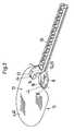
- FIG. 1shows a view of the device 1 from above, wherein the first storage area 2 associated part of the device 1, which is intended to receive the first component is shown.
- the devicecomprises a first storage area 2 for receiving a first component 5 and a second storage area 3 for receiving a second component 6 Fig. 1 an eruption is shown in the wall of the storage area 2 to expose your view of the component 5 hidden underneath.
- Each of the storage areas 2, 3may be formed in particular as a half-shell.
- the first storage area 2is separated from the second storage area 3 by a film 4, so that a closed chamber is formed between each of the two storage areas and the film.
- Each of the two storage areas 2, 3has a support element 31, 32.
- the support element 31, 32adjoins the closed chamber.
- the first storage area 2 and the second storage area 3can be sealed to form a seam 33 and, if appropriate, can additionally be connected or welded outside the seam 33 by a connecting element 34.
- the support element 31 and the storage area 2can consist of a wrapping film 38.
- the support element 32 and the storage area 3may consist of a wrapping film 39.
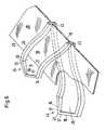
- Fig. 2shows a view of the device, for which the walls of the storage areas 2,3, the mixing channel 9 and a part of the first and second outlet channels 7, 8 have been removed.
- the film 4is partially omitted, so that the course of the second outlet channel 9 to is visible for entry into the mixing channel 9, which is provided downstream of the outlet channels 7,8.
- the mixing channel 9includes a mixing element 35. Between the first and second storage area 2,3 and the first and second outlet channel 7, 8 a kink 10 is arranged.
- the first storage area 2 and the first exit channel 7are arranged on the first side 11 of the film 4, the second storage area 3 and the second exit channel 8 are arranged on the second side 12 of the film 4.
- the first side 11is disposed opposite to the second side 12.
- a web 37is arranged.
- This web 37can be held in a Austragosstoff of a first holding element.
- the Austragosstoffis not shown here.
- An example of such a discharge aidcan be found in the W02006 / 079413 ,
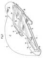
- Fig. 4ashows a further embodiment of the inventive device.
- Like-acting partsbear the same reference numerals as in FIG Fig. 1 to 3 and will not be described in detail unless their function differs from the first embodiment.
- the web 37is missing in this embodiment, so that this variant is particularly suitable for the manual discharge of the filling compound, which is located within the first or second storage areas.
- Fig. 4bIt is shown that the mixing channel 9 and the two storage areas 2, 3 are surrounded by a first and a second wrapping film 38, 39, which serves for receiving the components and for receiving the mixing element 35.
- a first and a second wrapping film 38, 39which serves for receiving the components and for receiving the mixing element 35.
- a second wrapping film 39is placed on a base, which has a recess in the shape of the second storage area 3 and a recess for the second outlet channel 8 and for the mixing channel 9.
- the wrapping film 39is placed on the pad or form so that it rests in all recesses on the substrate.
- the recess for the second storage area 3is not connected to the recess for the first outlet channel 7 or the mixing channel 9. Therefore, the recess of the second storage area 3 can be filled with the second component 6. If the second storage area 3 is filled with the second component 6, the second storage area 3 can also be covered with a film 40 and connected in a fluid-tight manner. The component 6 is thus enclosed in the storage area 3. However, it may be possible to dispense with the attachment of the film 40 in this case, as will be explained below.
- the mixing element 35is inserted into the recess for the mixing channel 9, and the second outlet channel 8 is inserted into the corresponding recess.
- the mixing element 35is integrally connected to the first and second outlet channel 8,9, so that an alignment of the parts against each other is eliminated.
- the second storage areadoes not necessarily have to be closed by a film 40, since in a subsequent working step the first wrapping film 38 together with the first storage area 2, in which the first component 5 is enclosed, onto the second wrapping film 39, the second component 6 and the mixing element is placed. The two components are thus separated from each other.
- the first wrapping film 38 and the second wrapping film 39are joined together along the supporting surfaces, that is, the part of the corresponding wrapping film which has no recess, so that on the one hand the second component 3 is enclosed in its storage area 3 as well as the mixing element 35 together with the first and second exit channels 7, 8 in the first and second cover sheets 38, 39 is included.
- another film 40can be placed on the second storage area and the second storage area 3 can thus also be closed by this film 40.
- This variantis advantageous when it comes to delays in the assembly of the device and / or the second component is not allowed to be exposed to air or is sensitive to light or there is a risk that the second component will enter the exit channel or even the mixing element.
- Fig. 5is the mixing element 35 and the corresponding outlet channels 7, 8 shown in detail.
- the mixing element 35 and the outlet channels 7, 8are designed as a single component, which is advantageously produced by injection molding.
- Each of the outlet channelsconsists of a bottom 18, 19 and each of a first side wall 20, 22 and a second side wall 21, 23rd
- At least one of the first and second outlet channels 7, 8has a bottom 18, 19.
- the bottomhas an end 29 facing the corresponding storage areas 2, 3, the kink 10 being formed by the end 29 of the floor.
- Each of the arms 13, 14, 15, 16may for this purpose have a cutting edge 17 facing the film 4, which in FIG Fig. 6 or Fig. 7 is shown.
- Fig. 6 and Fig. 7thus show a detail of in Fig. 1-3 or Fig. 4a respectively.
- Fig. 4billustrated device in the region of the kink 10.
- the outlet channel 7,8comprises a bottom 18, 19, on which the film 4 extends, and a first wall 20 and a second wall 21, wherein the arm 13, 14, 15, 16 from the bottom 18, 19 through the film 4th is disconnected.
- Each of the arms 13, 14, 15, 16is formed by at least one continuation of the first or second walls 20, 21, 22, 23.
- the separating element 24, 44each comprises a first and second arm 13, 14, 15, 16 which extends from the kink 10 in the direction of the corresponding storage area 2, 3.
- each of the first and second arms 13, 14, 15, 16are arranged adjacent to one another and form a tip 36, 41, on which a cutting edge 17 facing the film 4 is arranged.
- the separating element 24, which belongs to the first outlet channel 7,contains a recess 26.
- the separating element 44, which belongs to the second outlet channel 8,contains a recess 46.
- the recess 26is formed by the tip 36, the corresponding first and second arms 13, 14 , as well as the bottom 18 of the first outlet channel 7 surrounded.
- the recess 46is surrounded by the tip 41, the corresponding first and second arms 15, 16, and the bottom 19 of the second outlet channel 8.
- the corresponding outlet channel 7, 8each has a first and second wall 20, 21, 22, 23, which extends from the bottom 18, 19, wherein at least one of the arms 13, 14, 15, 16 to the corresponding first or second Wall 20, 21, 22, 23 connects.
- Each two of the adjacent armsconverge in the corresponding point 36, 41, which has a sharp edge on the side facing the film 4.
- the armsmay also have sharp edges on the side facing the film 4.
- the surface 36, 41 opposite surfacepreferably has a rounding. If one of the enveloping films 38, 39 comes to lie on this rounding, it remains intact, even if an external compressive force acts on the enveloping film.
- the roundingthus prevents the wrapping film from being damaged when it is loaded from the outside, for example when several devices are stacked on top of one another or during discharge Accidentally pressure is exerted on the storage area near the corresponding outlet channel.
- the film 4can be severed on the first side 11, when the angle between a foil 4 closing off the storage regions 2, 3 and the bottom 18 of the first discharge channel 7 is smaller than 180 °.
- the film 4can be severed on the second side 12, when the angle between a foil 4 closing the storage regions 2, and the bottom 19 of the second discharge channel 8 is greater than 180 °.
- Fig. 8is a section through the mixing channel 9 of a first variant shown.
- the mixing channelcontains a mixing element 35, which is accommodated in the enveloping films 38, 39.
- the mixing element 35has at least one protuberance 30, so that the enveloping film 38, 39 rests on the protuberance 30.
- the protuberance 30may be formed on opposite sides of the outer wall of the mixing element 35.
- the shape of the protuberance 30is such that the enveloping films 38, 39 each invest as close as possible to the protuberance 30, so that between the enveloping films 38, 39 and the mixing element 35 no voids are formed.
- the mixing elementpreferably has a quadrangular, in particular square cross section.
- Fig. 9shows a section through a mixing channel 9 according to a second variant.
- this mixing channel 9 and the mixing element 35 arranged in the mixing channelhas a circular cross-section.
- the protuberance 30has two surface pieces with concave curvature 42, 43 and a surface piece arranged between these two surface pieces with a preferably flat surface 45.
- the two surface pieces 42, 43could also be flat or have a convex curvature.
- the in Fig. 8 Flattened tipshown and forms the flat surface 45.
- the surface 45could also have a slight curvature or slope.
- the two enveloping films 38 and 39seal against the patches 42, 43 and the surface 45 and are joined together immediately thereafter to the surface 45, preferably by a seal or weld or a combination of these techniques. Alternatively or in addition to this, a seam may be provided.
- the device according to one of the preceding embodimentsis particularly suitable for the separate storage and the common discharge of multicomponent adhesives or multicomponent sealants. Another application is impression compounds for dental applications or filling materials.
- the holding elementmay be the hand of a user who wishes to discharge the two components from the device in order to supply them to a desired application.
Landscapes
- Chemical & Material Sciences (AREA)
- Chemical Kinetics & Catalysis (AREA)
- Engineering & Computer Science (AREA)
- Mechanical Engineering (AREA)
- Dispersion Chemistry (AREA)
- Containers And Packaging Bodies Having A Special Means To Remove Contents (AREA)
- Package Specialized In Special Use (AREA)
- Packages (AREA)
- Medical Preparation Storing Or Oral Administration Devices (AREA)
Description
Translated fromGermanDie Erfindung betrifft eine Vorrichtung zur Lagerung und Dosierung einer Mehrzahl von Komponenten, die unmittelbar vor Gebrauch miteinander vermischt und im vermischten Zustand einer Verwendung zugeführt werden sollen. Derartige Vorrichtungen werden beispielsweise zur Lagerung der einzelnen Komponenten eines Mehrkomponentenklebstoffs verwendet. Eine weitere Anwendung finden sie in der Lebensmittelindustrie oder zur Verpackung von medizinischen Präparaten. Allen diesen Vorrichtungen ist gemein, dass die einzelnen Komponenten bis zum Verbrauch in getrennten Vorratsbereichen, die verschliessbar sind, gelagert werden.The invention relates to a device for storing and dosing a plurality of components which are mixed together immediately prior to use and to be supplied in the mixed state of use. Such devices are used for example for storage of the individual components of a multi-component adhesive. Another application is found in the food industry or for the packaging of medical preparations. Common to all these devices is that the individual components are stored until they are consumed in separate storage areas that can be closed.
Werden derartige Vorrichtungen zum einmaligen Gebrauch konzipiert, werden sie auch als Blisterverpackungen bezeichnet. Eine Kammer einer Blisterverpackung für eine flüssige oder pulverförmige Füllmasse besteht in der Regel aus einer Tiefformfolie und einer Siegelfolie, welche die Füllmasse im Lagerzustand dichtend von der Umgebung abschliesst.If such devices are designed for single use, they are also referred to as blister packs. A chamber of a blister pack for a liquid or powdered filling material usually consists of a deep-forming film and a sealing film, which closes the filling material sealingly in the storage state from the environment.
In verschiedenen Anwendungen für Nahrungsmittel, Kosmetika, pharmazeutische Produkte, Dentalprodukte, Dichtungsmassen oder Klebstoffe werden mehrere Komponenten separat gelagert, bevor sie ihrer bestimmungsgemässen Verwendung zugeführt werden. Die Komponenten kommen aber gemeinsam, meist in gemischtem Zustand zur Anwendung. Hierzu werden Vorrichtungen eingesetzt, wie sie beispielsweise in der
Die Vorrichtung gemäss
An die beiden Vorratsbereiche kann ein Mischelement anschliessen, wie es beispielsweise für einen aus der
In dem ersten, in der
Nach anderen Ausführungsbeispielen der
Die zum Auseinanderdrücken der Trennstege oder zum Durchtrennen der Trennwand auf den Stössel auszuübende Kraft ist verhältnismässig gross, da die Trennstege oder Trennwand eine genügend grosse Wandstärke haben muss, um die Füllmasse vor Stössen und Beschädigungen bei Transport und Lagerung zu schützen und deren Austritt zu verhindern.The force to be pressed apart to separate the separating webs or to sever the dividing wall on the plunger is relatively large, since the dividing webs or dividing wall must have a sufficiently large wall thickness in order to protect the filling compound from impacts and damage during transport and storage and to prevent their escape.
Der Stössel ist für eine zu einmaligem Gebrauch bestimmte Vorrichtung dementsprechend klein, sodass es einiges Geschick erfordert, den Durchgang zu den Vorratsbereichen sicher zu öffnen, wenn die Komponenten der Füllmasse gemischt und ausgetragen werden sollen.The plunger is accordingly small for a single use device, so that it requires some skill to safely open the passage to the storage areas when the components of the filling are to be mixed and discharged.
Als Alternative wird in der
Das heisst aber, dass eine Komponente sich schon im Kanal und im Mischelement befinden kann, bevor die Öffnung des Durchgangs für die zweite Komponente abgeschlossen ist. Somit ist auch für die Betätigung dieses Öffnungsdorns Geschick und Erfahrung erforderlich.However, this means that one component may already be in the channel and in the mixing element before the opening of the passage for the second component is completed. Thus, skill and experience is required for the operation of this opening mandrel.
Es ist auch bekannt, eine Trennwand durch Verschiebung des Mischelements gemeinsam mit dem Gehäuse des Mischelements zu durchtrennen. Gemäss dieser Lösung müssen aber das Mischelement samt seinem Gehäuse als separates Bauteil bereitgestellt werden. Die beiden Bauteile müssen durch Verbindungselement derart dichtend verbunden werden, dass die Komponenten zu dem Mischelement und durch das Mischelement hindurch geführt werden, aber ein Austritt der Komponenten an anderer Stelle, insbesondere der Verbindung zwischen dem Bauteil, welches das Mischelement und sein Gehäuse umfasst, und den Vorratsbereichen sicher zu vermeiden. Diese Lösung ist somit für eine Vorrichtung zur einmaligen Anwendung zu aufwendig und teuer.It is also known to cut through a partition wall by displacement of the mixing element together with the housing of the mixing element. According to this solution, but the mixing element and its housing as be provided separate component. The two components must be so tightly connected by connecting element, that the components are passed to the mixing element and through the mixing element, but a leakage of the components elsewhere, in particular the connection between the component, which comprises the mixing element and its housing, and to safely avoid the storage areas. This solution is thus too complicated and expensive for a device for single use.
Daher ist es Aufgabe der Erfindung, eine einfach zu bedienende, kostengünstige Vorrichtung vorzusehen, die mittels eines einfachen Handgriffs unter Anwendung geringer Öffnungskräfte sicher geöffnet werden kann.It is therefore an object of the invention to provide an easy-to-use, inexpensive device that can be safely opened by means of a simple handle using low opening forces.
Diese Aufgabe wird durch die Vorrichtung zur Lagerung einer Mehrzahl von Komponenten, die zum gemeinsamen Verbrauch bestimmt sind, gelöst. Die Vorrichtung umfasst einen ersten Vorratsbereich zur Aufnahme einer ersten Komponente und einen zweiten Vorratsbereich zur Aufnahme einer zweiten Komponente. Der erste Vorratsbereich ist gegenüberliegend zum zweiten Vorratsbereich angeordnet. Das heisst, der erste Vorratsbereich befindet sich über oder unter dem zweiten Vorratsbereich. Der erste Vorratsbereich ist vom zweiten Vorratsbereich durch eine Folie getrennt, sodass sich der erste Vorratsbereich auf einer ersten Seite der Folie erstreckt und sich der zweite Vorratsbereich auf einer zweiten Seite der Folie erstreckt. Der erste Vorratsbereich ist mit einem ersten Austrittskanal verbindbar. Der zweite Vorratsbereich ist mit einem zweiten Austrittskanal verbindbar. Der erste Austrittskanal und der zweite Austrittskanal können in einen gemeinsamen Mischkanal münden. Zwischen dem ersten und zweiten Vorratsbereich und dem ersten und zweiten Austrittskanal ist eine linienförmige Knickstelle angeordnet. Unter einer linienförmigen Knickstelle ist eine Knickstelle zu verstehen, welche die Form einer Linie hat. Die Linie kann gerade oder gekrümmt sein.This object is achieved by the device for storing a plurality of components, which are intended for common consumption. The device comprises a first storage area for receiving a first component and a second storage area for receiving a second component. The first storage area is arranged opposite to the second storage area. That is, the first storage area is located above or below the second storage area. The first storage area is separated from the second storage area by a film, so that the first storage area extends on a first side of the film and the second storage area extends on a second side of the film. The first storage area can be connected to a first outlet channel. The second storage area can be connected to a second outlet channel. The first outlet channel and the second outlet channel can open into a common mixing channel. Between the first and second storage area and the first and second discharge channel a line-shaped kink is arranged. Under a line-shaped kink is a kink to understand, which has the shape of a line. The line can be straight or curved.
Im Mischkanal kann ein Mischelement angeordnet sein, um die Komponenten vor ihrer Verwendung homogen zu durchmischen. Das Mischelement kann insbesondere als statisches Mischelement ausgebildet sein.In the mixing channel, a mixing element may be arranged to homogeneously mix the components prior to their use. The mixing element may in particular be designed as a static mixing element.
Nach einem bevorzugten Ausführungsbeispiel sind der erste Vorratsbereich und der erste Austrittskanal auf ersten Seite der Folie angeordnet, der zweite Vorratsbereich und der zweite Austrittskanal auf der zweiten Seite der Folie angeordnet. Diese Anordnung ist besonders vorteilhaft, da die Füllmassen aus beiden Vorratsbereichen gleichzeitig ausgebracht werden könnten. Hierzu kann manuell Druck auf die beiden Vorratsbereiche ausgeübt werden, indem sie mit einer Hand zusammengedrückt werden. Alternativ dazu kann die Vorrichtung in ein Austraghilfsmittel eingespannt werden, mittels welchem ein Druck auf die Vorratsbereiche aufbringbar ist. Unter diesem Druck gibt die flexible Hülle der Vorratsbereiche nach. Das Volumen des Vorratsbereichs nimmt mit fortscheitendem Austrag kontinuierlich ab bis die Füllmasse die Vorratsbereiche vollständig verlassen hat. Die Wand des Vorratsbereichs kann ebenfalls eine Hüllfolie oder eine Mehrzahl von Hüllfolien umfassen.According to a preferred embodiment, the first storage area and the first exit channel are arranged on the first side of the film, the second storage area and the second exit channel are arranged on the second side of the film. This arrangement is particularly advantageous because the fillers from both supply areas could be applied simultaneously. For this purpose, pressure can be exerted manually on the two storage areas by being compressed with one hand. Alternatively, the device can be clamped in a Austraghilfsmittel by means of which a pressure on the storage areas can be applied. Under this pressure, the flexible shell of the storage areas yields. The volume of the storage area decreases continuously with progressing discharge until the filling material has completely left the storage areas. The wall of the storage area may also comprise a wrapping film or a plurality of wrapping films.
Zumindest einer der ersten und zweiten Austrittskanäle kann einen Boden aufweisen. Dieser Boden ist nach einem bevorzugten Ausführungsbeispiel einteilig mit den Austrittskanälen und kann sogar eine Einheit mit dem an die Austrittskanäle anschliessenden Mischelement ausbilden. Der Boden weist ein den entsprechenden Vorratsbereichen zugewendetes Ende auf, wobei die Knickstelle vom Ende des Bodens gebildet ist.At least one of the first and second exit channels may have a bottom. This floor is according to a preferred embodiment in one piece with the outlet channels and may even form a unit with the adjoining the outlet channels mixing element. The bottom has an end facing the corresponding storage areas, the kink being formed from the end of the floor.
Zumindest einer der Austrittskanäle weist ein Trennelement auf, welches sich über die Knickstelle hinaus in Richtung des dem entsprechenden Austrittskanal zugeordneten Vorratsbereichs erstreckt. Mittels des Trennelements kann die Folie, welche die erste Komponente im ersten Vorratsbereich dichtend hält und die zweite Komponente im zweiten Vorratsbereich dichtend hält, durchtrennt werden.At least one of the outlet channels has a separating element which extends beyond the kink point in the direction of the storage area associated with the corresponding outlet channel. By means of the separating element, the film, which seals the first component in the first storage area and holds the second component in the second storage area in a sealed manner, can be severed.
Das Trennelement enthält vorteilhafterweise eine Ausnehmung. Diese Ausnehmung gewährleistet, dass die durchtrennte Folie nicht den entsprechenden Austrittskanal blockiert.The separating element advantageously contains a recess. This recess ensures that the severed film does not block the corresponding exit channel.
Das Trennelement weist einen ersten und zweiten Arm auf, der sich über die Knickstelle hinaus in Richtung des dem Austrittskanal zugeordneten Vorratsbereichs erstreckt. Alternativ dazu kann auch der Vorratsbereich einen Arm aufweisen, der sich über die Knickstelle hinaus in Richtung des entsprechenden Austrittskanals erstreckt. Dieser Arm ist für den Fall, dass er vom Austrittskanal ausgeht derart mit dem Austrittskanal verbunden, dass er bei einer Bewegung des Austrittskanals dessen Bewegung mitmacht. Das heisst, dass durch Bewegung des Austrittskanals eine Bewegung des Arms erfolgt. Wird der Austrittkanal um die Knickstelle relativ zu den Vorratsbereichen mittels einer Drehbewegung bewegt, kommt der entsprechende Arm des Trennelements mit der Folie in Berührung und beginnt eine Druckkraft auf die Folie auszuüben. Durch diese Druckkraft kann die Folie geschwächt oder geritzt werden, sodass der Weg für die entsprechende Komponente in Richtung des Austrittskanals freigegeben wird.The separating element has a first and a second arm which extends beyond the kink point in the direction of the supply region associated with the outlet channel. Alternatively, the storage area can also have an arm which extends beyond the kink point in the direction of the corresponding outlet channel. This arm is in the event that it emanates from the outlet channel so connected to the outlet channel, that it participates in a movement of the outlet channel whose movement. This means that movement of the outlet channel causes movement of the arm. If the outlet channel is moved about the bend point relative to the storage areas by means of a rotary movement, the corresponding arm of the separating element comes into contact with the film and begins to exert a compressive force on the film. By this pressure force, the film can be weakened or scratched, so that the way for the corresponding component is released in the direction of the outlet channel.
Der Arm nach einem der vorhergehenden Ausführungsbeispiele weist hierzu eine der Folie zugewandte Schneidkante auf. Die Schneidkante ist insbesondere derart ausgestaltet, dass nach Berührung der Schneidkante mit der Folie unter Anwendung einer geringen Druckkraft eine schlitzförmige Öffnung in die Folie einbringbar ist. Die Schneidkante ist insbesondere an oder in der Nähe der Spitze des Trennelements angeordnet, an der Stelle also, an welcher die beiden Arme zusammenkommen.The arm according to one of the preceding embodiments has for this purpose a film facing the cutting edge. The cutting edge is in particular designed such that after contacting the cutting edge with the film using a low pressure force, a slot-shaped opening can be introduced into the film. The cutting edge is in particular arranged at or in the vicinity of the tip of the separating element, ie at the point where the two arms come together.
Zumindest je einer der ersten und zweiten Arme, die benachbart zueinander angeordnet sind, bilden eine Spitze aus, an welcher eine der Folie zugewandte Schneidkante angeordnet ist. Erstreckt sich die Schneidkante über zumindest einen Teil der der Folie zugewandten Seite des Arms und läuft diese Schneidkante in der Spitze insbesondere punktförmig zusammen, ist eine besonders geringe Druckkraft erforderlich, um die Folie zu durchtrennen, da die gesamte Druckkraft auf einen Punkt konzentriert werden kann und somit eine geringe Auslenkung des Kanals erforderlich ist, um ein Durchstossen der Folie zu bewirken.At least one each of the first and second arms, which are arranged adjacent to one another, form a tip, on which a cutting edge facing the film is arranged. If the cutting edge extends over at least part of the side of the arm facing the film and if this cutting edge in the tip runs together punctiform in particular, a particularly low compressive force is required to close the film cut as the entire compressive force can be concentrated to a point and thus a small deflection of the channel is required to cause a puncture of the film.
Nach einem besonders bevorzugten Ausführungsbeispiel ist die Ausnehmung von der Spitze, dem entsprechenden ersten und zweiten Arm, sowie dem Boden des entsprechenden Austrittskanals umgeben. Hierdurch ergibt sich die grösstmögliche Öffnung, sodass mit Sicherheit vermieden werden kann, dass ein Teil der durchtrennten Folie diese Öffnung wieder verschliesst und der Austrag einer der Komponenten sich auf Kosten der anderen Komponente verzögert und demzufolge das Mischungsverhältnis der beiden Komponenten in unzulässiger Weise verändert werden würde.According to a particularly preferred embodiment, the recess is surrounded by the tip, the corresponding first and second arm, as well as the bottom of the corresponding outlet channel. This results in the largest possible opening, so that it can be safely avoided that a part of the cut film closes this opening again and the discharge of one of the components is delayed at the expense of the other component and therefore the mixing ratio of the two components would be changed in an inadmissible manner ,
Der Austrittskanal umfasst einen Boden, sowie eine erste Wand und eine zweite Wand, die sich vom Boden aus erstreckt. Die Wand am Austrittskanal verhindert, dass eine Folie, welche den Austrittskanal im Rahmen der Montage verschliesst, am Boden aufliegt.The exit channel includes a bottom, and a first wall and a second wall extending from the bottom. The wall at the outlet channel prevents a film, which closes the outlet channel during the assembly, rests on the ground.
Zumindest einer der Arme kann an die entsprechende erste oder zweite Wand anschliessen. Insbesondere kann der Arm durch mindestens eine der ersten und zweiten Wände gebildet werden. Arm und Wände können Bestandteil eines einstückig gefertigten Mischelements sein. Ein derartiges Mischelement kann insbesondere als Kunststoffbauteil im Spritzgiessverfahren hergestellt sein.At least one of the arms can connect to the corresponding first or second wall. In particular, the arm may be formed by at least one of the first and second walls. Arm and walls can be part of a one-piece mixing element. Such a mixing element can be produced in particular as a plastic component by injection molding.
Die der Spitze gegenüberliegende Fläche kann eine Rundung aufweisen. Eine derartige Rundung ist insbesondere dann vorteilhaft, wenn das Trennelement von einer Folie umgeben ist, die bei der Lagerung der Vorrichtung nicht verletzt werden darf. Da die Vorratsbereiche von einer Hüllfolie umgeben sind, ist es möglich, auch die Austrittskanäle sowie das Mischelement mit dieser Hüllfolie in einem Arbeitsgang zu umhüllen. Diese Hüllfolie muss sich allerdings unter Fingerdruck verformen können, also flexibel sein. Gelangt diese Hüllfolie auf eine Kante, so wird sie durchtrennt, wie das bei Berührung des Trennelements mit der Folie zwischen den Vorratsbereichen erwünscht ist, aber im Fall der Hüllfolie in keinem Fall erwünscht ist, da die entsprechende Komponente durch das entstandene Leck austreten kann.The tip-opposite surface may be rounded. Such a rounding is particularly advantageous when the separating element is surrounded by a film that must not be injured during storage of the device. Since the storage areas are surrounded by a wrapping film, it is possible to wrap the discharge channels and the mixing element with this wrapping film in one operation. However, this wrapping film must be able to deform under finger pressure, so be flexible. If this wrapping film reaches an edge, it is severed, as when the separating element is in contact with the film between the layers Storage areas is desired, but in the case of the wrapping film is desired in any case, since the corresponding component can escape through the resulting leak.
Die Folie ist entlang der Knickstelle knickbar, sodass im geknickten Zustand die Folie durch den Arm und/oder das Trennelement durchtrennbar ist.The film can be bent along the kink, so that in the folded state, the film can be severed by the arm and / or the separating element.
Das Trennelement ist derart angeordnet, dass mittels des Trennelements die Folie auf der ersten Seite durchtrennbar ist, wenn der Winkel zwischen einer die Vorratsbereiche verschliessenden Folie und zumindest eines der Böden der ersten und zweiten Austrittskanäle kleiner als 180° ist.The separating element is arranged such that the film on the first side can be severed by means of the separating element when the angle between a foil closing off the storage regions and at least one of the bottoms of the first and second outlet channels is less than 180 °.
Alternativ oder zusätzlich kann das Trennelement derart angeordnet sein, dass mittels des Trennelements die Folie auf der zweiten Seite durchtrennbar ist, wenn der Winkel zwischen einer die Vorratsbereiche verschliessenden Folie und zumindest eines der Böden der ersten und zweiten Austrittskanäle grösser als 180° ist.Alternatively or additionally, the separating element can be arranged such that the film on the second side can be severed by means of the separating element if the angle between a foil closing off the supply regions and at least one of the bottoms of the first and second outlet channels is greater than 180 °.
Mittels des Trennelements ist die Folie auf der Seite des gegenüberliegenden Vorratsbereichs durchtrennbar, wenn der Winkel zwischen der Folie auf der ersten Seite der Knickstelle, welche den Vorratsbereich enthält und der zweiten Seite der Knickstelle, welche den Austrittskanal enthält, grösser als 180° ist.By means of the separating element, the film on the side of the opposite storage area can be severed when the angle between the film on the first side of the kink, which contains the storage area and the second side of the kink, which contains the outlet channel, is greater than 180 °.
Nach einem der vorhergehenden Ausführungsbeispiele kann das Mischelement in der Folie aufgenommen sein, sodass die Herstellung eines Rohrs zur Aufnahme des Mischelements entfallen kann. Die Wände des Mischelements werden dabei von einer Hüllfolie zumindest teilweise umschlossen. Insbesondere wirkt die Hüllfolie, die oberhalb des Mischelements angeordnet ist, mit einer Hüllfolie zusammen, die unterhalb des Mischelements angeordnet ist. Vorteilhafterweise ist die Hüllfolie jeweils dieselbe Hüllfolie, welche zumindest einen der ersten oder zweiten Vorratsbereiche umgibt.According to one of the preceding embodiments, the mixing element can be accommodated in the film, so that the production of a tube for receiving the mixing element can be omitted. The walls of the mixing element are thereby at least partially enclosed by a wrapping film. In particular, the wrapping film, which is arranged above the mixing element, cooperates with a wrapping film, which is arranged below the mixing element. Advantageously, the wrapping film is respectively the same enveloping film surrounding at least one of the first or second storage areas.
An den beiden Seitenkanten des Mischelements liegen die beiden Hüllfolien aufeinander auf. Hier berühren sich die beiden Hüllfolien entlang der Auflagebereiche und können an diesen Auflagebereichen miteinander verbunden sein, sodass der Mischkanal fluiddicht in den Hüllfolien aufgenommen ist. Die Verbindung kann vorteilhafterweise durch Schweissen oder Versiegeln erfolgen. Alternativ oder in Ergänzung hierzu kann eine Naht vorgesehen sein.At the two side edges of the mixing element, the two enveloping films lie on each other. Here, the two enveloping films touch each other along the support regions and can be connected to one another at these contact regions, so that the mixing channel is received in a fluid-tight manner in the enveloping films. The connection can advantageously be effected by welding or sealing. Alternatively or in addition to this, a seam may be provided.
Hierbei bleibt ein Hohlraum zwischen Mischelement und der Hüllfolie bestehen. Wenn der Mischkanal einen kreisförmigen Querschnitt aufweist, ist dieser Hohlraum klein, es kann aber dennoch vorkommen, dass es beim Austragen der ersten und zweiten Komponente zu Undichtigkeiten kommt. Die Hüllfolie kann von der Wand des Mischelements ablösen, wenn durch die Komponenten ein Druck auf die innere Oberfläche der Hüllfolie ausgeübt wird.Here, a cavity between the mixing element and the enveloping film remains. If the mixing channel has a circular cross section, this cavity is small, but it can still happen that leaks occur when discharging the first and second components. The cover sheet may peel off the wall of the mixing element when pressure is applied to the inner surface of the cover sheet by the components.
Zur Erhöhung der mechanischen Stabilität des Mischkanals kann vorgesehen sein, dass das Mischelement zumindest eine Ausstülpung enthält, sodass die Hüllfolie auf der Ausstülpung anliegt. Hierdurch ergibt sich der unerwartete Vorteil, dass die Hüllfolie eng am Mischelement anliegt, das heisst insbesondere das Mischelement berührt und auch unter dem Druck der auszutragenden Komponenten ein Ablösen der Hüllfolie vom Mischelement vermieden werden kann.To increase the mechanical stability of the mixing channel can be provided that the mixing element contains at least one protuberance, so that the enveloping film rests on the protuberance. This results in the unexpected advantage that the cladding sheet fits snugly against the mixing element, that is, in particular touches the mixing element and also under the pressure of the components to be discharged, a detachment of the cladding film can be avoided by the mixing element.
Ein Verfahren zum Austrag einer ersten und einer zweiten Komponente aus der Vorrichtung nach einem der vorhergehenden Ausführungsbeispiele umfasst die Schritte:
- Halten des ersten Vorratsbereichs und zweiten Vorratsbereichs mit einem ersten Halteelement
- Halten des ersten und zweiten Austrittskanals mit einem zweiten Halteelement,
- Bewegen des ersten Halteelements relativ zum zweiten Halteelement entlang einer ersten Drehrichtung, sodass eine Drehbewegung des ersten und zweiten Vorratsbereichs um die Knickstelle erfolgt wobei die Folie auf dem Trennelement zu liegen kommt
- Durchtrennen der Folie mittels des Trennelements sodass der entsprechende Vorratsbereich mit dem entsprechenden Austrittskanal verbunden wird, Ausüben einer Druckkraft auf den ersten Vorratsbereich und den zweiten Vorratsbereich
- Austragen der ersten Komponente aus dem ersten Vorratsbereich in den ersten Austrittskanal und gleichzeitiges Austragen der zweiten Komponente aus dem zweiten Vorratsbereich in den zweiten Austrittskanal,
- Vermischen der ersten Komponente mit der zweiten Komponente im Mischkanal zur Ausbildung eines Gemischs
- Austragen des Gemischs aus dem Mischkanal.
- Holding the first storage area and the second storage area with a first holding element
- Holding the first and second outlet channel with a second holding element,
- Moving the first holding element relative to the second holding element along a first rotational direction, so that a rotational movement of the first and second storage area takes place around the kink wherein the film comes to lie on the separating element
- Cutting the film by means of the separating element so that the corresponding storage area is connected to the corresponding outlet channel, exerting a compressive force on the first storage area and the second storage area
- Discharging the first component from the first storage area into the first discharge channel and simultaneously discharging the second component from the second storage area into the second discharge channel,
- Mixing the first component with the second component in the mixing channel to form a mixture
- Discharging the mixture from the mixing channel.
Im Anschluss an das Bewegen des ersten und zweiten Vorratsbereichs um die Knickstelle kann ein Bewegen des ersten Halteelements relativ zum zweiten Halteelement entlang einer der ersten Drehrichtung entgegengesetzten Drehrichtung erfolgen, sodass eine Drehbewegung des ersten und zweiten Vorratsbereichs um die Knickstelle derart erfolgt, dass die Folie auf dem Trennelement zu liegen kommt und die Folie mittels des Trennelements durchtrennt wird.Following the movement of the first and second storage area about the kink point, the first holding element can move relative to the second holding element along a direction of rotation opposite to the first direction of rotation, so that a rotational movement of the first and second storage area around the kink occurs in such a way that the film rests the separating element comes to rest and the film is severed by means of the separating element.
Das Halteelement kann eine Hand umfassen oder ein Austraghilfsmittel. Das Austraghilfsmittel dient der Aufnahme der Vorrichtung. Die Vorrichtung wird im Inneren des Austraghilfsmittels gehalten und durch Manipulation des Austraghilfsmittels werden die Komponenten aus der Vorrichtung ausgetragen.The holding element may comprise a hand or a Austraghilfsmittel. The Austraghilfsmittel serves to receive the device. The device is held in the interior of the Austraghilfsmittels and by manipulation of the Austraghilfsmittels the components are discharged from the device.
Die beiden Vorratsbereiche der Vorrichtung können mit der Folie oder der Hüllfolie bevorzugt durch thermisches Schweissen, Ultraschallschweissen oder Laserschweissen dicht miteinander verbunden werden. Als besonders einfaches und sicheres Verfahren hat sich das thermische Schweissen herausgestellt. Hierzu werden gut schweissbare Tiefziehfolien, die insbesondere Polypropylen oder Polyethylen enthalten, durch das Zusammenpressen von zwei gegenüberliegenden beheizten Stempeln eines Schweisswerkzeugs zusammengeschweisst.The two storage areas of the device can preferably be tightly connected to one another by thermal welding, ultrasonic welding or laser welding with the film or the wrapping film. A particularly simple and safe method, the thermal welding has been found. These are well weldable thermoforming films, the in particular polypropylene or polyethylene, welded together by the compression of two opposing heated punches of a welding tool.
Nachfolgend wird die Erfindung anhand der Zeichnungen erläutert. Es zeigen:
- Fig. 1
- eine Ansicht eines ersten Ausführungsbeispiels der erfindungsgemässen Vorrichtung
- Fig. 2
- eine Ansicht der Vorrichtung nach
Fig. 1 , wobei die Wände der Vorratsbereiche, der Mischkanal und ein Teil der Abdeckung der Austrittskanäle entfernt worden sind. - Fig. 3
- die Ansicht gemäss
Fig. 2 mit dem zweiten Vorratsbereich - Fig. 4a
- eine Seitenansicht eines zweiten Ausführungsbeispiels der erfindungsgemässen Vorrichtung
- Fig. 4b
- eine Ansicht der Vorrichtung gemäss
Fig. 4a von oben - Fig. 5
- eine Ansicht eines Ausführungsbeispiels für ein Mischelement
- Fig. 6
- ein Detail an der Knickstelle
- Fig. 7
- das Detail gemäss
Fig. 6 nach Durchführung einer Knickbewegung - Fig. 8
- einen Schnitt durch einen Mischkanal nach einer ersten Variante
- Fig. 9
- einen Schnitt durch einen Mischkanal nach einer zweiten Variante
- Fig. 1
- a view of a first embodiment of the inventive device
- Fig. 2
- a view of the device according to
Fig. 1 , wherein the walls of the storage areas, the mixing channel and a part of the cover of the outlet channels have been removed. - Fig. 3
- the view according to
Fig. 2 with the second storage area - Fig. 4a
- a side view of a second embodiment of the inventive device
- Fig. 4b
- a view of the device according to
Fig. 4a from above - Fig. 5
- a view of an embodiment of a mixing element
- Fig. 6
- a detail at the kink
- Fig. 7
- the detail according to
Fig. 6 after performing a kinking movement - Fig. 8
- a section through a mixing channel according to a first variant
- Fig. 9
- a section through a mixing channel according to a second variant
Mit einer erfindungsgemässen Vorrichtung zur Lagerung einer Mehrzahl von Komponenten, die zum gemeinsamen Verbrauch bestimmt sind, wie sie in den
Die Vorrichtung umfasst einen ersten Vorratsbereich 2 zur Aufnahme einer ersten Komponente 5 und einen zweiten Vorratsbereich 3 zur Aufnahme einer zweiten Komponente 6. In
Für besonders reaktive Komponenten kann es notwendig sein, eine spezielle Auskleidung oder Beschichtung an der Innenwand des entsprechenden Vorratsbereichs 2,3 vorzusehen.For particularly reactive components, it may be necessary to provide a special lining or coating on the inner wall of the corresponding
Der erste Vorratsbereich 2 und der erste Austrittskanal 7 sind auf ersten Seite 11 der Folie 4 angeordnet, der zweite Vorratsbereich 3 und der zweite Austrittskanal 8 sind auf der zweiten Seite 12 der Folie 4 angeordnet. Die erste Seite 11 ist gegenüberliegend zur zweiten Seite 12 angeordnet.The
Zumindest einer der Austrittskanäle 7, 8 weist einen Arm 13, 14, 15, 16 auf, der sich über die Knickstelle 10 hinaus in Richtung des dem entsprechenden Austrittskanal 7, 8 zugeordneten Vorratsbereichs 2, 3 erstreckt. Je zwei benachbarte Arme, die zu einem Austrittskanal gehörig sind, sind miteinander verbunden, Gemäss
Für das Ausführungsbeispiel gemäss
In
Zur Herstellung einer Vorrichtung gemäss eines der vorhergehenden Ausführungsbeispiele wird eine erste Hüllfolie 38 auf eine Unterlage oder Form gelegt, die eine Ausnehmung in der Form des ersten Vorratsbereichs 2 sowie eine Ausnehmung für den ersten Austrittskanal 7 sowie für den Mischkanal 9 aufweist. Die Hüllfolie wird derart auf die Unterlage gelegt, dass sie in allen Ausnehmungen auf der Unterlage aufliegt. Die Ausnehmung für den ersten Vorratsbereich 2 ist nicht mit der Ausnehmung für den ersten Austrittskanal 7 oder den Mischkanal 9 verbunden. Daher kann die Ausnehmung des zweiten Vorratsbereichs 2 mit der ersten Komponente 5 befüllt werden. Ist der Vorratsbereich 2 mit der ersten Komponente 5 gefüllt, wird der erste Vorratsbereich 2 mit einer Folie 4 abgedeckt und fluiddicht verschlossen. Die Komponente 5 ist somit im Vorratsbereich 2 eingeschlossen.To produce a device according to one of the preceding exemplary embodiments, a
Anschliessend wird eine zweite Hüllfolie 39 auf eine Unterlage gelegt, die eine Ausnehmung in der Form des zweiten Vorratsbereichs 3 sowie eine Ausnehmung für den zweiten Austrittskanal 8 sowie für den Mischkanal 9 aufweist. Die Hüllfolie 39 wird derart auf die Unterlage oder Form gelegt, dass sie in allen Ausnehmungen auf der Unterlage aufliegt. Die Ausnehmung für den zweiten Vorratsbereich 3 ist nicht mit der Ausnehmung für den ersten Austrittskanal 7 oder den Mischkanal 9 verbunden. Daher kann die Ausnehmung des zweiten Vorratsbereichs 3 mit der zweiten Komponente 6 befüllt werden. Ist der zweite Vorratsbereich 3 mit der zweiten Komponente 6 gefüllt, kann auch der zweite Vorratsbereich 3 mit einer Folie 40 abgedeckt und fluiddicht verbunden werden. Die Komponente 6 ist somit im Vorratsbereich 3 eingeschlossen. Allerdings kann auf das Anbringen der Folie 40 in diesem Fall unter Umständen auch verzichtet werden, wie nachfolgend erläutert wird.Subsequently, a
In einem nächsten Schritt wird das Mischelement 35 in die Ausnehmung für den Mischkanal 9 eingelegt, sowie der zweite Austrittskanal 8 in die entsprechende Ausnehmung eingelegt. Vorteilhafterweise ist das Mischelement 35 mit dem ersten und zweiten Austrittskanal 8,9 einteilig verbunden, sodass eine Ausrichtung der Teile gegeneinander entfällt. Der zweite Vorratsbereich braucht in diesem Fall nicht unbedingt durch eine Folie 40 verschlossen zu werden, da in einem nachfolgenden Arbeitsschritt die erste Hüllfolie 38 samt dem ersten Vorratsbereich 2, in welchem die erste Komponente 5 eingeschlossen ist, auf die zweite Hüllfolie 39, die zweite Komponente 6 sowie das Mischelement aufgelegt wird. Die beiden Komponenten sind somit voneinander getrennt.In a next step, the mixing
Die erste Hüllfolie 38 und die zweite Hüllfolie 39 werden entlang der Auflageflächen, das heisst, des Teils der entsprchenden Hüllfolie, der keine Ausnehmung aufweist, miteinander verbunden, sodass einerseits die zweite Komponente 3 in ihrem Vorratsbereich 3 eingeschlossen wird sowie auch das Mischelement 35 samt den ersten und zweiten Austrittskanälen 7, 8 in der ersten und zweiten Hüllfolie 38, 39 eingeschlossen ist.The
In einem Zwischenschritt kann eine weitere Folie 40 auf den zweiten Vorratsbereich gelegt werden und der zweite Vorratsbereich 3 somit ebenfalls durch diese Folie 40 verschlossen werden. Diese Variante ist vorteilhaft, wenn es beim Zusammenbau der Vorrichtung zu Verzögerungen kommt und/oder die zweite Komponente nicht der Luft ausgesetzt werden darf oder lichtempfindlich ist oder die Gefahr besteht, dass die zweite Komponente in den Austrittskanal oder sogar das Mischelement gelangt.In an intermediate step, another film 40 can be placed on the second storage area and the
Nachfolgend soll im Detail ausgeführt werden, wie die beiden in ihren Vorratsbereichen 2, 3 eingeschlossenen Komponenten 5, 6 gleichzeitig ausgetragen werden können und vermischt werden können.Below is to be explained in detail how the two enclosed in their
In
Der Boden 18, sowie der Boden 19, von welchem nur eine Kante sichtbar ist, können in ein plattenförmiges Element 41 übergehen. Zumindest einer der ersten und zweiten Austrittskanäle 7, 8 weist einen Boden 18, 19 auf. Der Boden weist ein den entsprechenden Vorratsbereichen 2, 3 zugewendetes Ende 29 auf, wobei die Knickstelle 10 vom Ende 29 des Bodens gebildet ist.The bottom 18, as well as the bottom 19, of which only one edge is visible, can pass into a plate-shaped
Jeder der Arme 13, 14, 15, 16 kann hierzu eine der Folie 4 zugewandte Schneidkante 17 aufweisen, welche in
Der Austrittskanal 7,8 umfasst einen Boden 18, 19, auf welchem sich die Folie 4 erstreckt, sowie eine erste Wand 20 und eine zweite Wand 21, wobei der Arm 13, 14, 15, 16 vom Boden 18, 19 durch die Folie 4 getrennt ist.The
Jeder der Arme 13, 14, 15, 16 wird durch mindestens eine Fortsetzung der ersten oder zweiten Wände 20, 21, 22, 23 gebildet. Das Trennelement 24, 44 umfasst je einen ersten und zweiten Arm 13, 14, 15, 16, der sich von der Knickstelle 10 in Richtung des entsprechenden Vorratsbereichs 2, 3 erstreckt.Each of the
Alternativ kann der jeweilige Boden 18, 19 des entsprechenden Austrittskanals 8,9 in ein Trennelement 24, 44 münden, was zeichnerisch nicht dargestellt ist. Zumindest je einer der ersten und zweiten Arme 13, 14, 15, 16 sind benachbart zueinander angeordnet und bilden eine Spitze 36, 41 aus, an welcher eine der Folie 4 zugewandte Schneidkante 17 angeordnet ist.Alternatively, the respective bottom 18, 19 of the
Das Trennelement 24, welches zum ersten Austrittskanal 7 gehört, enthält eine Ausnehmung 26. Das Trennelement 44, welches zum zweiten Austrittskanal 8 gehört, enthält eine Ausnehmung 46. Die Ausnehmung 26 ist von der Spitze 36, dem entsprechenden ersten und zweiten Arm 13, 14, sowie dem Boden 18 des ersten Austrittskanals 7 umgeben. Die Ausnehmung 46 ist von der Spitze 41, dem entsprechenden ersten und zweiten Arm 15, 16, sowie dem Boden 19 des zweiten Austrittskanals 8 umgeben.The separating
Der entsprechende Austrittskanal 7, 8 weist je eine erste und zweite Wand 20, 21, 22, 23 auf, die sich vom Boden 18, 19 aus erstreckt, wobei zumindest einer der Arme 13, 14, 15, 16 an die entsprechende erste oder zweite Wand 20, 21, 22, 23 anschliesst. Je zwei der benachbarten Arme laufen in der entsprechenden Spitze 36, 41 zusammen, welche auf der Seite, die der Folie 4 zugewendet ist, eine scharfe Kante aufweist. In Ergänzung hierzu können auch die Arme scharfe Kanten auf der Seite aufweisen, die der Folie 4 zugewendet ist.The
Die der Spitze 36, 41 gegenüberliegende Fläche weist vorzugsweise eine Rundung auf. Wenn auf diese Rundung eine der Hüllfolien 38, 39 zu liegen kommt, bleibt sie intakt, auch wenn eine äussere Druckkraft auf die Hüllfolie wirkt. Durch die Rundung wird somit verhindert, dass die Hüllfolie einen Schaden nimmt, wenn sie von aussen belastet wird, beispielsweise, wenn mehrere Vorrichtungen übereinander gestapelt werden oder beim Austrag versehentlich Druck auf den Vorratsbereich in der Nähe des entsprechenden Austrittskanals ausgeübt wird.The
Mittels des Trennelements 24 ist die Folie 4 auf der ersten Seite 11 durchtrennbar, wenn der Winkel zwischen einer die Vorratsbereiche 2,3 verschliessenden Folie 4 und dem Boden 18 des ersten Austrittskanals 7 kleiner als 180° ist.By means of the separating
Mittels des Trennelements 44 ist die Folie 4 auf der zweiten Seite 12 durchtrennbar, wenn der Winkel zwischen einer die Vorratsbereiche 2,3 verschliessenden Folie 4 und dem Boden 19 des zweiten Austrittskanals 8 grösser als 180° ist.By means of the separating
In
Selbstverständlich könnte die Oberfläche 45 auch eine schwache Krümmung oder Neigung aufweisen. Die beiden Hüllfolien 38 und 39 legen sich an die Flächenstücke 42, 43 und die Oberfläche 45 dichtend an und werden unmittelbar anschliessend an die Oberfläche 45 miteinander verbunden, vorzugsweise durch eine Versiegelung oder Verschweissung oder eine Kombination dieser Verfahren. Alternativ oder in Ergänzung hierzu kann eine Naht vorgesehen sein.Of course, the
Die Vorrichtung nach einem der vorhergehenden Ausführungsbeispiele eignet sich insbesondere für die getrennte Lagerung und den gemeinsamen Austrag von Mehrkomponentenklebstoffen oder Mehrkomponentendichtmassen. Eine weitere Anwendung sind Abformmassen für Anwendungen im Dentalbereich oder Füllmassen.The device according to one of the preceding embodiments is particularly suitable for the separate storage and the common discharge of multicomponent adhesives or multicomponent sealants. Another application is impression compounds for dental applications or filling materials.
Sollen die beiden in dem ersten und zweiten Vorratsbereich 2,3 befindlichen ersten und zweiten Komponenten 5,6 aus einer Vorrichtung ausgetragen werden, sind folgende Schritte erforderlich:
- Halten eines ersten
Endes 27, enthaltend die ersten und zweiten Vorratsbereiche 2,3 mit einem ersten Halteelement, - Halten eines zweiten
Endes 28, enthaltend zumindest einen der ersten und zweiten Austrittskanäle 7,8 mit einem zweiten Halteelement, - Bewegen des ersten Halteelements relativ zum zweiten Halteelement in einer ersten Drehrichtung, sodass eine Drehbewegung des ersten
Endes 27 um dieKnickstelle 10 erfolgt, wobei die Folie 4auf dem Arm - Durchtrennen der Folie 4 mittels des
Arms dem entsprechenden Austrittskanal - Ausüben einer Druckkraft auf den ersten
Vorratsbereich 2 und den zweitenVorratsbereich 3 - Austragen der ersten Komponente 5 aus dem ersten Vorratsbereich 2 in den ersten
Austrittskanal 7 und gleichzeitiges Austragen der zweiten Komponente 6 aus dem zweiten Vorratsbereich 3 in den zweitenAustrittskanal 8, Vermischen der ersten Komponente 5 mit der zweiten Komponente 6im Mischkanal 9 zur Ausbildung eines Gemischs, - Austragen des Gemischs aus
dem Mischkanal 9.
- Holding a
first end 27 containing the first andsecond storage regions - Holding a
second end 28 containing at least one of the first andsecond exit channels - Moving the first holding element relative to the second holding element in a first rotational direction, so that a rotational movement of the
first end 27 takes place about thebending point 10, wherein the film 4 comes to lie on thearm - Severing the film 4 by means of the
arm storage area corresponding exit channel - Exerting a compressive force on the
first storage area 2 and thesecond storage area 3 - Discharging the
first component 5 from thefirst storage area 2 into thefirst discharge channel 7 and simultaneously discharging thesecond component 6 from thesecond storage area 3 into thesecond discharge channel 8, Mixing thefirst component 5 with thesecond component 6 in the mixingchannel 9 to form a mixture, - Discharging the mixture from the mixing
channel 9.
Im Anschluss an das Bewegen des ersten und zweiten Vorratsbereichs 2,3 um die Knickstelle 10 erfolgt ein Bewegen des ersten Halteelements relativ zum zweiten Halteelement entlang einer der ersten Drehrichtung entgegengesetzten Drehrichtung erfolgt, sodass eine Drehbewegung des ersten und zweiten Vorratsbereichs 2,3 um die Knickstelle 10 derart erfolgt, dass die Folie 4 auf dem Trennelement 24 zu liegen kommt, Durchtrennen der Folie 4 mittels des Trennelements 4.Following the movement of the first and
Das Halteelement kann insbesondere die Hand eines Benutzers sein, welcher die beiden Komponenten aus der Vorrichtung austragen will, um sie einer gewünschten Applikation zuzuführen.In particular, the holding element may be the hand of a user who wishes to discharge the two components from the device in order to supply them to a desired application.
Claims (12)
- An apparatus (1) for the storage of a plurality of components which are designed for joint use, including a first storage region (2) for the reception of a first component (5) and a second storage region (3) for the reception of a second component (6), wherein the first storage region (2) is arranged disposed opposite the second storage region (3), wherein the first storage region (2) is separated from the second storage region (3) by a film (4) so that the first storage region (2) extends on a first side (11) of the film (4) and the second storage region (3) extends on a second side (12) of the film (4), wherein the first storage region (2) can be connected to a first discharge passage (7), wherein the second storage region (3) can be connected to a second discharge passage (8), wherein the first discharge passage (7) and the second discharge passage (8) open into a common mixing passage (9), wherein a linear kinking site (10) is arranged between the first and second storage regions (2, 3) and the first and second discharge passages (7,8), wherein at least one of the discharge passages (7, 8) has a parting element (24, 44) which extends beyond the kinking site (10) in the direction of the storage region (2, 3) associated with the corresponding discharge passage (7, 8), wherein the parting element includes a first and second arm (13, 14, 15, 16) which extends from the kinking site (10) in the direction of the corresponding storage region (2, 3),characterized in that at least one of each of the first and second arms (13, 14, 15, 16) which are arranged adjacent to one another form a tip (36, 41) at which a cutting edge (17) facing the film (4) is arranged.
- An apparatus in accordance with claim 1, wherein the first storage region (2) and the first discharge passage (7) are arranged on the first side (11) of the film (4), and the second storage region (3) and the second discharge passage (8) are arranged on the second side (12) of the film (4).
- An apparatus in accordance with one of the preceding claims, wherein at least one of the first and second discharge passages (7, 8) has a base (18, 19) and the base has an end (29) facing the corresponding storage region (2, 3), with the kinking site (10) being formed by the end (29) of the base.
- An apparatus in accordance with any one of the preceding claims, wherein the parting element (24, 44) contains a cut-out (26, 46).
- An apparatus in accordance with claim 1, wherein the cut-out (26, 46) is surrounded by the tip (36, 41), by the corresponding first and second arms (13, 14, 15, 16) and by the base (18, 19) of the corresponding discharge passage.
- An apparatus in accordance with any one of the claims 3 to 5, wherein the discharge passage (7, 8) has a first or second wall (20, 21, 22, 23) which extends from the base (18, 19), with at least one of the arms (13, 14, 15, 16) adjoining the corresponding first or second walls (20, 21, 22, 23).
- An apparatus in accordance with any one of the claims 1, 5 or 6, wherein the surface disposed opposite the tip (36, 41) has a rounded portion.
- An apparatus in accordance with any one of the preceding claims, wherein the parting element (24) is arranged so that the film (4) can be parted on the first side (11) by means of the parting element when the angle between a film (4) closing the storage regions (2, 3) and the base of the first and second discharge passages is less than 180° and/or wherein the film (4) can be parted on the second side (12) by means of the parting element when the angle between a film (4) closing the storage regions and at least one of the bases of the first and second passages is greater than 180°.
- An apparatus in accordance with any one of the preceding claims, wherein the mixing element (35) is received in the film (4).
- An apparatus in accordance with claim 9, wherein the mixing element (35) contains at least one protuberance (30) so that the film (4) contacts the protuberance (30).
- A method for the dispensing of a first component and of a second component from an apparatus in accordance with any one of the preceding claims, including the steps:holding the first and second storage regions using a first holding element;holding the first discharge passage and the second discharge passage using a second holding element;moving the first holding element relative to the second holding element in a first rotational direction so that a rotational movement of the first and second storage regions takes place about the kinking site, with the film coming to lie on the parting element;parting the film by means of the parting element so that the corresponding storage region is connected to the corresponding discharge passage;exerting a compressive force onto the first storage region and the second storage region;dispensing the first component from the first storage region into the first discharge passage and simultaneously dispensing the second component from the second storage region into the second discharge passage;mixing the first component with the second component in the mixing passage to form a mixture,discharging the mixture from the mixing passage.
- A method in accordance with claim 11, wherein subsequent to the movement of the first and second storage regions about the kinking site, a movement of the first holding element takes place relative to the second holding element along a rotational direction opposed to the first rotational direction so that a rotational movement of the first and second storage regions takes place about the kinking site such that the film comes to lie on the parting element, and dividing the film by means of the parting element.
Priority Applications (1)
| Application Number | Priority Date | Filing Date | Title |
|---|---|---|---|
| EP10167263AEP2277800B1 (en) | 2009-07-23 | 2010-06-25 | Device for storing and proportioning a number of components |
Applications Claiming Priority (2)
| Application Number | Priority Date | Filing Date | Title |
|---|---|---|---|
| EP09166235 | 2009-07-23 | ||
| EP10167263AEP2277800B1 (en) | 2009-07-23 | 2010-06-25 | Device for storing and proportioning a number of components |
Publications (2)
| Publication Number | Publication Date |
|---|---|
| EP2277800A1 EP2277800A1 (en) | 2011-01-26 |
| EP2277800B1true EP2277800B1 (en) | 2013-04-03 |
Family
ID=41429307
Family Applications (1)
| Application Number | Title | Priority Date | Filing Date |
|---|---|---|---|
| EP10167263ANot-in-forceEP2277800B1 (en) | 2009-07-23 | 2010-06-25 | Device for storing and proportioning a number of components |
Country Status (8)
| Country | Link |
|---|---|
| US (1) | US9321577B2 (en) |
| EP (1) | EP2277800B1 (en) |
| JP (1) | JP5893239B2 (en) |
| KR (1) | KR101754172B1 (en) |
| CN (1) | CN101961615B (en) |
| BR (1) | BRPI1002721A2 (en) |
| ES (1) | ES2403079T3 (en) |
| TW (1) | TW201119734A (en) |
Families Citing this family (8)
| Publication number | Priority date | Publication date | Assignee | Title |
|---|---|---|---|---|
| EP2277801A1 (en)* | 2009-07-23 | 2011-01-26 | Sulzer Mixpac AG | Device for storing and proportioning a number of components |
| US8556128B2 (en)* | 2010-11-12 | 2013-10-15 | William A. Harper | Dispensing channel pump |
| US9776203B2 (en)* | 2012-12-14 | 2017-10-03 | Sulzer Mixpac Ag | Dispensing apparatus for a multi-component mass |
| US9527106B2 (en) | 2013-10-31 | 2016-12-27 | Nordson Corporation | Applicator and method for dispensing a viscous fluid |
| EP3075345A1 (en)* | 2015-04-02 | 2016-10-05 | DENTSPLY DETREY GmbH | Unit dose package |
| PL3095727T3 (en)* | 2015-05-19 | 2018-11-30 | Fischerwerke Gmbh & Co. Kg | Multi-component container which can be pressed out by hand |
| EP3342478A1 (en)* | 2016-12-29 | 2018-07-04 | Sulzer Mixpac AG | Static mixer, a kit of parts and use of said static mixer |
| DE102017112440A1 (en)* | 2017-06-06 | 2018-12-06 | Shin-Etsu Silicones Europe B.V. | Container and dosing device for viscous materials |
Family Cites Families (22)
| Publication number | Priority date | Publication date | Assignee | Title |
|---|---|---|---|---|
| CH398453A (en)* | 1961-10-25 | 1966-03-15 | Friedrich Richard Schlatter Ko | Containers for the transport, storage and mixing of different substances |
| CH674717A5 (en)* | 1987-11-10 | 1990-07-13 | Profil Ag | Mixing device for at least two cartridges - has mixing head, semi-outer welded shells, supplies, strips or screw conveyor |
| US4952068A (en)* | 1989-03-21 | 1990-08-28 | Flint Theodore R | Static mixing device and container |
| EP0442406B1 (en)* | 1990-02-14 | 1995-07-26 | Material Engineering Technology Laboratory, Inc. | Filled and sealed, self-contained mixing container |
| US5161715A (en)* | 1991-03-25 | 1992-11-10 | Giannuzzi Anthony C | Double-barreled epoxy injection gun |
| DE4222049C2 (en)* | 1992-07-04 | 1996-11-14 | Pharmacia Gmbh | Two-chamber bag |
| GB9817578D0 (en)* | 1998-08-12 | 1998-10-07 | Cambridge Consultants | Pack |
| US6287612B1 (en)* | 1998-12-01 | 2001-09-11 | Nestec S.A. | Liquid food products and package therefore |
| CN2364782Y (en)* | 1998-12-30 | 2000-02-23 | 谢国煌 | On-the-go mug with straw |
| US6260735B1 (en)* | 2000-05-12 | 2001-07-17 | Colgate-Palmolive Company | Uniform dispensing dual chamber sachet |
| US6612769B2 (en)* | 2000-12-13 | 2003-09-02 | Innovative Properties Company | Package and dispensing actuator for multiple-component compositions |
| FR2826641B1 (en)* | 2001-06-29 | 2003-09-05 | Oreal | DEVICE FOR THE SIMULTANEOUS DISPENSING OF TWO SEPARATELY PACKAGED PRODUCTS |
| US6845883B2 (en)* | 2001-10-18 | 2005-01-25 | Kenneth H. Pieri | Toothpaste dispenser |
| US7192179B2 (en)* | 2003-07-08 | 2007-03-20 | Angeletta Joseph G | Dual mixing system for liquid and lotion applicators |
| DE202005001203U1 (en)* | 2005-01-26 | 2006-06-14 | Sulzer Chemtech Ag | Multicomponent foil container |
| US7325703B2 (en)* | 2005-06-16 | 2008-02-05 | R.P. Scherer Technologies, Inc. | Multi-cavity blister package for storing and dispensing flowable substances |
| US20070269253A1 (en)* | 2006-05-05 | 2007-11-22 | John Caro | Compound mixing and dispensing device |
| EP1947028B1 (en) | 2007-01-18 | 2012-02-01 | Sulzer Mixpac AG | Device for storing and proportioning a number of components |
| TW200836982A (en)* | 2007-01-18 | 2008-09-16 | Sulzer Chemtech Ag | A device for the storage and metering of a plurality of components |
| CA2679441A1 (en)* | 2007-03-14 | 2008-09-18 | Poly-D, Llc | Dispenser with dual pump system |
| US20090114677A1 (en)* | 2007-11-05 | 2009-05-07 | Geoffrey Catherwood Stuart | Dual Receptacle Symmetrical Package for Liquids |
| EP2277801A1 (en)* | 2009-07-23 | 2011-01-26 | Sulzer Mixpac AG | Device for storing and proportioning a number of components |
- 2010
- 2010-06-25EPEP10167263Apatent/EP2277800B1/ennot_activeNot-in-force
- 2010-06-25ESES10167263Tpatent/ES2403079T3/enactiveActive
- 2010-07-19USUS12/804,307patent/US9321577B2/ennot_activeExpired - Fee Related
- 2010-07-20TWTW099123808Apatent/TW201119734A/enunknown
- 2010-07-21BRBRPI1002721-1Apatent/BRPI1002721A2/ennot_activeIP Right Cessation
- 2010-07-22JPJP2010164743Apatent/JP5893239B2/ennot_activeExpired - Fee Related
- 2010-07-22CNCN201010235270.2Apatent/CN101961615B/ennot_activeExpired - Fee Related
- 2010-07-23KRKR1020100071329Apatent/KR101754172B1/ennot_activeExpired - Fee Related
Also Published As
| Publication number | Publication date |
|---|---|
| US9321577B2 (en) | 2016-04-26 |
| US20110017771A1 (en) | 2011-01-27 |
| EP2277800A1 (en) | 2011-01-26 |
| JP5893239B2 (en) | 2016-03-23 |
| ES2403079T3 (en) | 2013-05-14 |
| CN101961615B (en) | 2015-07-22 |
| CN101961615A (en) | 2011-02-02 |
| KR101754172B1 (en) | 2017-07-05 |
| BRPI1002721A2 (en) | 2012-04-03 |
| KR20110010074A (en) | 2011-01-31 |
| TW201119734A (en) | 2011-06-16 |
| JP2011026008A (en) | 2011-02-10 |
Similar Documents
| Publication | Publication Date | Title |
|---|---|---|
| EP2277800B1 (en) | Device for storing and proportioning a number of components | |
| EP1555952B1 (en) | Device for storing and dispensing viscous substances | |
| EP1246765B1 (en) | Adapter, device and method for sampling from a multichamber bag, use of said adapter and bag packaging | |
| EP1982922B1 (en) | Container and method for opening a container | |
| DE60112323T2 (en) | PACKAGING FOR MULTICOMPONENT COMPOSITIONS | |
| DE2363904B2 (en) | FLEXIBLE BAG PACKING MADE OF PLASTIC FILM | |
| DE3789024T2 (en) | METHOD AND DEVICE FOR PREFORMING AN OUTPUT CHANNEL IN THE SEALING ZONE OF A BAG. | |
| EP0787655B1 (en) | Apparatus for emptying a sleeve-bag | |
| EP1334047A1 (en) | Device for storing and dispensing flowable compositions | |
| DE2649316C2 (en) | Double chamber container for the administration of two single doses or two single components and process for its production | |
| EP1021356A1 (en) | Multi-chamber container | |
| DE3513976A1 (en) | LIQUID PACKING AND METHOD AND DEVICE FOR PRODUCING THE SAME | |
| DE3519955A1 (en) | PACKING FOR LIQUIDS WITH EDGE PROTECTION, METHOD FOR PRODUCING THE SAME AND DEVICE FOR IMPLEMENTING THE METHOD | |
| EP2780257A1 (en) | Packaging for multi-component compositions | |
| EP2606926A1 (en) | Multi-chamber mixing container | |
| EP1609739B1 (en) | Single-use dispensing device and method of manufacturing a single-use dispensing device | |
| EP2511194A2 (en) | Film cartridge and method for producing a film cartridge | |
| EP2906481B1 (en) | Method for producing a sheet-material container | |
| DE102005000832A1 (en) | Chemical container for use in multi-component reaction comprises base film with recesses for chemicals and upper film sealed onto base film | |
| EP1108656B1 (en) | Multicomponent container for storing and distributing liquid or pasty products | |
| EP2284085B1 (en) | Packaged ready meal and method for its production | |
| EP0343266A1 (en) | Method for manufacturing containers from a web and apparatus for carrying out this method | |
| WO2001085569A1 (en) | Device for storing and mixing pasty materials | |
| EP2277801A1 (en) | Device for storing and proportioning a number of components | |
| EP1947028B1 (en) | Device for storing and proportioning a number of components |
Legal Events
| Date | Code | Title | Description |
|---|---|---|---|
| PUAI | Public reference made under article 153(3) epc to a published international application that has entered the european phase | Free format text:ORIGINAL CODE: 0009012 | |
| AK | Designated contracting states | Kind code of ref document:A1 Designated state(s):AL AT BE BG CH CY CZ DE DK EE ES FI FR GB GR HR HU IE IS IT LI LT LU LV MC MK MT NL NO PL PT RO SE SI SK SM TR | |
| AX | Request for extension of the european patent | Extension state:BA ME RS | |
| 17P | Request for examination filed | Effective date:20110726 | |
| GRAP | Despatch of communication of intention to grant a patent | Free format text:ORIGINAL CODE: EPIDOSNIGR1 | |
| RIC1 | Information provided on ipc code assigned before grant | Ipc:B65D 81/32 20060101AFI20120903BHEP | |
| GRAP | Despatch of communication of intention to grant a patent | Free format text:ORIGINAL CODE: EPIDOSNIGR1 | |
| GRAS | Grant fee paid | Free format text:ORIGINAL CODE: EPIDOSNIGR3 | |
| GRAA | (expected) grant | Free format text:ORIGINAL CODE: 0009210 | |
| AK | Designated contracting states | Kind code of ref document:B1 Designated state(s):AL AT BE BG CH CY CZ DE DK EE ES FI FR GB GR HR HU IE IS IT LI LT LU LV MC MK MT NL NO PL PT RO SE SI SK SM TR | |
| REG | Reference to a national code | Ref country code:GB Ref legal event code:FG4D Free format text:NOT ENGLISH | |
| REG | Reference to a national code | Ref country code:AT Ref legal event code:REF Ref document number:604578 Country of ref document:AT Kind code of ref document:T Effective date:20130415 Ref country code:CH Ref legal event code:NV Representative=s name:SULZER MANAGEMENT AG PATENTABTEILUNG/0067, CH Ref country code:CH Ref legal event code:EP | |
| REG | Reference to a national code | Ref country code:IE Ref legal event code:FG4D Free format text:LANGUAGE OF EP DOCUMENT: GERMAN | |
| REG | Reference to a national code | Ref country code:ES Ref legal event code:FG2A Ref document number:2403079 Country of ref document:ES Kind code of ref document:T3 Effective date:20130514 | |
| REG | Reference to a national code | Ref country code:DE Ref legal event code:R096 Ref document number:502010002751 Country of ref document:DE Effective date:20130529 | |
| REG | Reference to a national code | Ref country code:NL Ref legal event code:T3 | |
| PG25 | Lapsed in a contracting state [announced via postgrant information from national office to epo] | Ref country code:SI Free format text:LAPSE BECAUSE OF FAILURE TO SUBMIT A TRANSLATION OF THE DESCRIPTION OR TO PAY THE FEE WITHIN THE PRESCRIBED TIME-LIMIT Effective date:20130403 | |
| REG | Reference to a national code | Ref country code:LT Ref legal event code:MG4D | |
| PG25 | Lapsed in a contracting state [announced via postgrant information from national office to epo] | Ref country code:LT Free format text:LAPSE BECAUSE OF FAILURE TO SUBMIT A TRANSLATION OF THE DESCRIPTION OR TO PAY THE FEE WITHIN THE PRESCRIBED TIME-LIMIT Effective date:20130403 Ref country code:SE Free format text:LAPSE BECAUSE OF FAILURE TO SUBMIT A TRANSLATION OF THE DESCRIPTION OR TO PAY THE FEE WITHIN THE PRESCRIBED TIME-LIMIT Effective date:20130403 Ref country code:IS Free format text:LAPSE BECAUSE OF FAILURE TO SUBMIT A TRANSLATION OF THE DESCRIPTION OR TO PAY THE FEE WITHIN THE PRESCRIBED TIME-LIMIT Effective date:20130803 Ref country code:NO Free format text:LAPSE BECAUSE OF FAILURE TO SUBMIT A TRANSLATION OF THE DESCRIPTION OR TO PAY THE FEE WITHIN THE PRESCRIBED TIME-LIMIT Effective date:20130703 Ref country code:PT Free format text:LAPSE BECAUSE OF FAILURE TO SUBMIT A TRANSLATION OF THE DESCRIPTION OR TO PAY THE FEE WITHIN THE PRESCRIBED TIME-LIMIT Effective date:20130805 Ref country code:FI Free format text:LAPSE BECAUSE OF FAILURE TO SUBMIT A TRANSLATION OF THE DESCRIPTION OR TO PAY THE FEE WITHIN THE PRESCRIBED TIME-LIMIT Effective date:20130403 Ref country code:GR Free format text:LAPSE BECAUSE OF FAILURE TO SUBMIT A TRANSLATION OF THE DESCRIPTION OR TO PAY THE FEE WITHIN THE PRESCRIBED TIME-LIMIT Effective date:20130704 | |
| PG25 | Lapsed in a contracting state [announced via postgrant information from national office to epo] | Ref country code:LV Free format text:LAPSE BECAUSE OF FAILURE TO SUBMIT A TRANSLATION OF THE DESCRIPTION OR TO PAY THE FEE WITHIN THE PRESCRIBED TIME-LIMIT Effective date:20130403 Ref country code:CY Free format text:LAPSE BECAUSE OF FAILURE TO SUBMIT A TRANSLATION OF THE DESCRIPTION OR TO PAY THE FEE WITHIN THE PRESCRIBED TIME-LIMIT Effective date:20130403 Ref country code:BG Free format text:LAPSE BECAUSE OF FAILURE TO SUBMIT A TRANSLATION OF THE DESCRIPTION OR TO PAY THE FEE WITHIN THE PRESCRIBED TIME-LIMIT Effective date:20130703 Ref country code:HR Free format text:LAPSE BECAUSE OF FAILURE TO SUBMIT A TRANSLATION OF THE DESCRIPTION OR TO PAY THE FEE WITHIN THE PRESCRIBED TIME-LIMIT Effective date:20130403 Ref country code:PL Free format text:LAPSE BECAUSE OF FAILURE TO SUBMIT A TRANSLATION OF THE DESCRIPTION OR TO PAY THE FEE WITHIN THE PRESCRIBED TIME-LIMIT Effective date:20130403 | |
| BERE | Be: lapsed | Owner name:SULZER MIXPAC A.G. Effective date:20130630 | |
| PG25 | Lapsed in a contracting state [announced via postgrant information from national office to epo] | Ref country code:MC Free format text:LAPSE BECAUSE OF FAILURE TO SUBMIT A TRANSLATION OF THE DESCRIPTION OR TO PAY THE FEE WITHIN THE PRESCRIBED TIME-LIMIT Effective date:20130403 Ref country code:DK Free format text:LAPSE BECAUSE OF FAILURE TO SUBMIT A TRANSLATION OF THE DESCRIPTION OR TO PAY THE FEE WITHIN THE PRESCRIBED TIME-LIMIT Effective date:20130403 Ref country code:CZ Free format text:LAPSE BECAUSE OF FAILURE TO SUBMIT A TRANSLATION OF THE DESCRIPTION OR TO PAY THE FEE WITHIN THE PRESCRIBED TIME-LIMIT Effective date:20130403 Ref country code:EE Free format text:LAPSE BECAUSE OF FAILURE TO SUBMIT A TRANSLATION OF THE DESCRIPTION OR TO PAY THE FEE WITHIN THE PRESCRIBED TIME-LIMIT Effective date:20130403 Ref country code:SK Free format text:LAPSE BECAUSE OF FAILURE TO SUBMIT A TRANSLATION OF THE DESCRIPTION OR TO PAY THE FEE WITHIN THE PRESCRIBED TIME-LIMIT Effective date:20130403 | |
| PLBE | No opposition filed within time limit | Free format text:ORIGINAL CODE: 0009261 | |
| STAA | Information on the status of an ep patent application or granted ep patent | Free format text:STATUS: NO OPPOSITION FILED WITHIN TIME LIMIT | |
| PG25 | Lapsed in a contracting state [announced via postgrant information from national office to epo] | Ref country code:RO Free format text:LAPSE BECAUSE OF FAILURE TO SUBMIT A TRANSLATION OF THE DESCRIPTION OR TO PAY THE FEE WITHIN THE PRESCRIBED TIME-LIMIT Effective date:20130403 | |
| REG | Reference to a national code | Ref country code:CH Ref legal event code:NV Representative=s name:DR. GRAF AND PARTNER AG INTELLECTUAL PROPERTY, CH | |
| 26N | No opposition filed | Effective date:20140106 | |
| REG | Reference to a national code | Ref country code:IE Ref legal event code:MM4A | |
| PG25 | Lapsed in a contracting state [announced via postgrant information from national office to epo] | Ref country code:BE Free format text:LAPSE BECAUSE OF NON-PAYMENT OF DUE FEES Effective date:20130630 | |
| REG | Reference to a national code | Ref country code:DE Ref legal event code:R097 Ref document number:502010002751 Country of ref document:DE Effective date:20140106 | |
| PG25 | Lapsed in a contracting state [announced via postgrant information from national office to epo] | Ref country code:IE Free format text:LAPSE BECAUSE OF NON-PAYMENT OF DUE FEES Effective date:20130625 | |
| PG25 | Lapsed in a contracting state [announced via postgrant information from national office to epo] | Ref country code:MT Free format text:LAPSE BECAUSE OF FAILURE TO SUBMIT A TRANSLATION OF THE DESCRIPTION OR TO PAY THE FEE WITHIN THE PRESCRIBED TIME-LIMIT Effective date:20130403 | |
| PG25 | Lapsed in a contracting state [announced via postgrant information from national office to epo] | Ref country code:SM Free format text:LAPSE BECAUSE OF FAILURE TO SUBMIT A TRANSLATION OF THE DESCRIPTION OR TO PAY THE FEE WITHIN THE PRESCRIBED TIME-LIMIT Effective date:20130403 | |
| PG25 | Lapsed in a contracting state [announced via postgrant information from national office to epo] | Ref country code:TR Free format text:LAPSE BECAUSE OF FAILURE TO SUBMIT A TRANSLATION OF THE DESCRIPTION OR TO PAY THE FEE WITHIN THE PRESCRIBED TIME-LIMIT Effective date:20130403 | |
| PG25 | Lapsed in a contracting state [announced via postgrant information from national office to epo] | Ref country code:MK Free format text:LAPSE BECAUSE OF FAILURE TO SUBMIT A TRANSLATION OF THE DESCRIPTION OR TO PAY THE FEE WITHIN THE PRESCRIBED TIME-LIMIT Effective date:20130403 Ref country code:LU Free format text:LAPSE BECAUSE OF NON-PAYMENT OF DUE FEES Effective date:20130625 Ref country code:HU Free format text:LAPSE BECAUSE OF FAILURE TO SUBMIT A TRANSLATION OF THE DESCRIPTION OR TO PAY THE FEE WITHIN THE PRESCRIBED TIME-LIMIT; INVALID AB INITIO Effective date:20100625 | |
| REG | Reference to a national code | Ref country code:FR Ref legal event code:PLFP Year of fee payment:7 | |
| REG | Reference to a national code | Ref country code:AT Ref legal event code:MM01 Ref document number:604578 Country of ref document:AT Kind code of ref document:T Effective date:20150625 | |
| PG25 | Lapsed in a contracting state [announced via postgrant information from national office to epo] | Ref country code:AT Free format text:LAPSE BECAUSE OF NON-PAYMENT OF DUE FEES Effective date:20150625 | |
| REG | Reference to a national code | Ref country code:FR Ref legal event code:PLFP Year of fee payment:8 | |
| PGFP | Annual fee paid to national office [announced via postgrant information from national office to epo] | Ref country code:IS Payment date:20170530 Year of fee payment:8 | |
| PGFP | Annual fee paid to national office [announced via postgrant information from national office to epo] | Ref country code:ES Payment date:20170724 Year of fee payment:8 | |
| REG | Reference to a national code | Ref country code:FR Ref legal event code:PLFP Year of fee payment:9 | |
| PGFP | Annual fee paid to national office [announced via postgrant information from national office to epo] | Ref country code:DE Payment date:20180625 Year of fee payment:9 Ref country code:NL Payment date:20180620 Year of fee payment:9 | |
| PGFP | Annual fee paid to national office [announced via postgrant information from national office to epo] | Ref country code:FR Payment date:20180620 Year of fee payment:9 | |
| PG25 | Lapsed in a contracting state [announced via postgrant information from national office to epo] | Ref country code:AL Free format text:LAPSE BECAUSE OF FAILURE TO SUBMIT A TRANSLATION OF THE DESCRIPTION OR TO PAY THE FEE WITHIN THE PRESCRIBED TIME-LIMIT Effective date:20130403 | |
| PGFP | Annual fee paid to national office [announced via postgrant information from national office to epo] | Ref country code:IT Payment date:20180627 Year of fee payment:9 Ref country code:GB Payment date:20180620 Year of fee payment:9 | |
| REG | Reference to a national code | Ref country code:CH Ref legal event code:PL | |
| PG25 | Lapsed in a contracting state [announced via postgrant information from national office to epo] | Ref country code:LI Free format text:LAPSE BECAUSE OF NON-PAYMENT OF DUE FEES Effective date:20180630 Ref country code:CH Free format text:LAPSE BECAUSE OF NON-PAYMENT OF DUE FEES Effective date:20180630 | |
| REG | Reference to a national code | Ref country code:ES Ref legal event code:FD2A Effective date:20190916 | |
| PG25 | Lapsed in a contracting state [announced via postgrant information from national office to epo] | Ref country code:ES Free format text:LAPSE BECAUSE OF NON-PAYMENT OF DUE FEES Effective date:20180626 | |
| REG | Reference to a national code | Ref country code:DE Ref legal event code:R119 Ref document number:502010002751 Country of ref document:DE | |
| REG | Reference to a national code | Ref country code:NL Ref legal event code:MM Effective date:20190701 | |
| GBPC | Gb: european patent ceased through non-payment of renewal fee | Effective date:20190625 | |
| PG25 | Lapsed in a contracting state [announced via postgrant information from national office to epo] | Ref country code:GB Free format text:LAPSE BECAUSE OF NON-PAYMENT OF DUE FEES Effective date:20190625 Ref country code:DE Free format text:LAPSE BECAUSE OF NON-PAYMENT OF DUE FEES Effective date:20200101 Ref country code:NL Free format text:LAPSE BECAUSE OF NON-PAYMENT OF DUE FEES Effective date:20190701 Ref country code:IT Free format text:LAPSE BECAUSE OF NON-PAYMENT OF DUE FEES Effective date:20190625 | |
| PG25 | Lapsed in a contracting state [announced via postgrant information from national office to epo] | Ref country code:FR Free format text:LAPSE BECAUSE OF NON-PAYMENT OF DUE FEES Effective date:20190630 |