EP2277682A2 - Process and apparatus for making transversely drawn films with substantially uniaxial orientation - Google Patents
Process and apparatus for making transversely drawn films with substantially uniaxial orientationDownload PDFInfo
- Publication number
- EP2277682A2 EP2277682A2EP10180145AEP10180145AEP2277682A2EP 2277682 A2EP2277682 A2EP 2277682A2EP 10180145 AEP10180145 AEP 10180145AEP 10180145 AEP10180145 AEP 10180145AEP 2277682 A2EP2277682 A2EP 2277682A2
- Authority
- EP
- European Patent Office
- Prior art keywords
- film
- stretching
- opposing
- stretched
- along
- Prior art date
- Legal status (The legal status is an assumption and is not a legal conclusion. Google has not performed a legal analysis and makes no representation as to the accuracy of the status listed.)
- Granted
Links
- 238000000034methodMethods0.000titleclaimsabstractdescription100
- 230000008569processEffects0.000titleabstractdescription46
- 238000012545processingMethods0.000claimsdescription10
- 239000010408filmSubstances0.000abstractdescription412
- 239000012788optical filmSubstances0.000abstractdescription20
- 230000003287optical effectEffects0.000description16
- 239000000463materialSubstances0.000description14
- 230000007246mechanismEffects0.000description12
- 238000011144upstream manufacturingMethods0.000description9
- 230000002829reductive effectEffects0.000description8
- 230000037303wrinklesEffects0.000description8
- 230000008602contractionEffects0.000description7
- 229920000728polyesterPolymers0.000description6
- 230000009471actionEffects0.000description4
- 230000007547defectEffects0.000description4
- 238000009826distributionMethods0.000description4
- 238000012986modificationMethods0.000description4
- 230000004048modificationEffects0.000description4
- -1polyethylene naphthalatePolymers0.000description4
- 238000000926separation methodMethods0.000description4
- 238000013459approachMethods0.000description3
- 230000006835compressionEffects0.000description3
- 238000007906compressionMethods0.000description3
- 238000013461designMethods0.000description3
- 238000010586diagramMethods0.000description3
- 239000000835fiberSubstances0.000description3
- 238000010438heat treatmentMethods0.000description3
- 229920006302stretch filmPolymers0.000description3
- 238000012546transferMethods0.000description3
- 241000237503PectinidaeSpecies0.000description2
- 230000002411adverseEffects0.000description2
- 230000003466anti-cipated effectEffects0.000description2
- 230000008901benefitEffects0.000description2
- 230000008859changeEffects0.000description2
- 238000000576coating methodMethods0.000description2
- 239000002131composite materialSubstances0.000description2
- 238000010924continuous productionMethods0.000description2
- 238000001816coolingMethods0.000description2
- 230000000694effectsEffects0.000description2
- 230000009477glass transitionEffects0.000description2
- 230000000670limiting effectEffects0.000description2
- 239000007788liquidSubstances0.000description2
- 210000003739neckAnatomy0.000description2
- 230000037361pathwayEffects0.000description2
- 229920003207poly(ethylene-2,6-naphthalate)Polymers0.000description2
- 239000011112polyethylene naphthalateSubstances0.000description2
- 235000020637scallopNutrition0.000description2
- 239000004743PolypropyleneSubstances0.000description1
- 238000010521absorption reactionMethods0.000description1
- 238000010923batch productionMethods0.000description1
- 238000005452bendingMethods0.000description1
- 230000015572biosynthetic processEffects0.000description1
- 238000007796conventional methodMethods0.000description1
- 239000013039cover filmSubstances0.000description1
- 239000013078crystalSubstances0.000description1
- 229920001887crystalline plasticPolymers0.000description1
- 238000002425crystallisationMethods0.000description1
- 230000008025crystallizationEffects0.000description1
- 230000007423decreaseEffects0.000description1
- 230000003247decreasing effectEffects0.000description1
- 238000011161developmentMethods0.000description1
- 230000018109developmental processEffects0.000description1
- 239000013013elastic materialSubstances0.000description1
- 230000005606hygroscopic expansionEffects0.000description1
- 230000006872improvementEffects0.000description1
- 230000003993interactionEffects0.000description1
- 238000003475laminationMethods0.000description1
- 238000004519manufacturing processMethods0.000description1
- 230000000873masking effectEffects0.000description1
- 238000002844meltingMethods0.000description1
- 230000008018meltingEffects0.000description1
- 230000001151other effectEffects0.000description1
- 230000000737periodic effectEffects0.000description1
- 230000000704physical effectEffects0.000description1
- 239000002985plastic filmSubstances0.000description1
- 229920002492poly(sulfone)Polymers0.000description1
- 229920000139polyethylene terephthalatePolymers0.000description1
- 239000005020polyethylene terephthalateSubstances0.000description1
- 229920001155polypropylenePolymers0.000description1
- 230000010411postconditioningEffects0.000description1
- 230000000644propagated effectEffects0.000description1
- 230000001902propagating effectEffects0.000description1
- 238000010791quenchingMethods0.000description1
- 230000000171quenching effectEffects0.000description1
- 230000005855radiationEffects0.000description1
- 230000009467reductionEffects0.000description1
- 238000012552reviewMethods0.000description1
- 230000011218segmentationEffects0.000description1
- 239000007787solidSubstances0.000description1
- 238000006467substitution reactionMethods0.000description1
- 230000002123temporal effectEffects0.000description1
- 239000012815thermoplastic materialSubstances0.000description1
Images


Classifications
- B—PERFORMING OPERATIONS; TRANSPORTING
- B29—WORKING OF PLASTICS; WORKING OF SUBSTANCES IN A PLASTIC STATE IN GENERAL
- B29C—SHAPING OR JOINING OF PLASTICS; SHAPING OF MATERIAL IN A PLASTIC STATE, NOT OTHERWISE PROVIDED FOR; AFTER-TREATMENT OF THE SHAPED PRODUCTS, e.g. REPAIRING
- B29C55/00—Shaping by stretching, e.g. drawing through a die; Apparatus therefor
- B29C55/02—Shaping by stretching, e.g. drawing through a die; Apparatus therefor of plates or sheets
- B29C55/04—Shaping by stretching, e.g. drawing through a die; Apparatus therefor of plates or sheets uniaxial, e.g. oblique
- B29C55/08—Shaping by stretching, e.g. drawing through a die; Apparatus therefor of plates or sheets uniaxial, e.g. oblique transverse to the direction of feed
- B—PERFORMING OPERATIONS; TRANSPORTING
- B29—WORKING OF PLASTICS; WORKING OF SUBSTANCES IN A PLASTIC STATE IN GENERAL
- B29C—SHAPING OR JOINING OF PLASTICS; SHAPING OF MATERIAL IN A PLASTIC STATE, NOT OTHERWISE PROVIDED FOR; AFTER-TREATMENT OF THE SHAPED PRODUCTS, e.g. REPAIRING
- B29C55/00—Shaping by stretching, e.g. drawing through a die; Apparatus therefor
- B—PERFORMING OPERATIONS; TRANSPORTING
- B29—WORKING OF PLASTICS; WORKING OF SUBSTANCES IN A PLASTIC STATE IN GENERAL
- B29C—SHAPING OR JOINING OF PLASTICS; SHAPING OF MATERIAL IN A PLASTIC STATE, NOT OTHERWISE PROVIDED FOR; AFTER-TREATMENT OF THE SHAPED PRODUCTS, e.g. REPAIRING
- B29C2793/00—Shaping techniques involving a cutting or machining operation
- B29C2793/009—Shaping techniques involving a cutting or machining operation after shaping
- B—PERFORMING OPERATIONS; TRANSPORTING
- B29—WORKING OF PLASTICS; WORKING OF SUBSTANCES IN A PLASTIC STATE IN GENERAL
- B29C—SHAPING OR JOINING OF PLASTICS; SHAPING OF MATERIAL IN A PLASTIC STATE, NOT OTHERWISE PROVIDED FOR; AFTER-TREATMENT OF THE SHAPED PRODUCTS, e.g. REPAIRING
- B29C55/00—Shaping by stretching, e.g. drawing through a die; Apparatus therefor
- B29C55/02—Shaping by stretching, e.g. drawing through a die; Apparatus therefor of plates or sheets
- B29C55/20—Edge clamps
- B—PERFORMING OPERATIONS; TRANSPORTING
- B29—WORKING OF PLASTICS; WORKING OF SUBSTANCES IN A PLASTIC STATE IN GENERAL
- B29C—SHAPING OR JOINING OF PLASTICS; SHAPING OF MATERIAL IN A PLASTIC STATE, NOT OTHERWISE PROVIDED FOR; AFTER-TREATMENT OF THE SHAPED PRODUCTS, e.g. REPAIRING
- B29C69/00—Combinations of shaping techniques not provided for in a single one of main groups B29C39/00 - B29C67/00, e.g. associations of moulding and joining techniques; Apparatus therefore
- B29C69/001—Combinations of shaping techniques not provided for in a single one of main groups B29C39/00 - B29C67/00, e.g. associations of moulding and joining techniques; Apparatus therefore a shaping technique combined with cutting, e.g. in parts or slices combined with rearranging and joining the cut parts
- B—PERFORMING OPERATIONS; TRANSPORTING
- B29—WORKING OF PLASTICS; WORKING OF SUBSTANCES IN A PLASTIC STATE IN GENERAL
- B29K—INDEXING SCHEME ASSOCIATED WITH SUBCLASSES B29B, B29C OR B29D, RELATING TO MOULDING MATERIALS OR TO MATERIALS FOR MOULDS, REINFORCEMENTS, FILLERS OR PREFORMED PARTS, e.g. INSERTS
- B29K2067/00—Use of polyesters or derivatives thereof, as moulding material
- B29K2067/003—PET, i.e. poylethylene terephthalate
- B—PERFORMING OPERATIONS; TRANSPORTING
- B29—WORKING OF PLASTICS; WORKING OF SUBSTANCES IN A PLASTIC STATE IN GENERAL
- B29K—INDEXING SCHEME ASSOCIATED WITH SUBCLASSES B29B, B29C OR B29D, RELATING TO MOULDING MATERIALS OR TO MATERIALS FOR MOULDS, REINFORCEMENTS, FILLERS OR PREFORMED PARTS, e.g. INSERTS
- B29K2995/00—Properties of moulding materials, reinforcements, fillers, preformed parts or moulds
- B29K2995/0037—Other properties
- B29K2995/005—Oriented
- B29K2995/0051—Oriented mono-axially
- B—PERFORMING OPERATIONS; TRANSPORTING
- B29—WORKING OF PLASTICS; WORKING OF SUBSTANCES IN A PLASTIC STATE IN GENERAL
- B29L—INDEXING SCHEME ASSOCIATED WITH SUBCLASS B29C, RELATING TO PARTICULAR ARTICLES
- B29L2011/00—Optical elements, e.g. lenses, prisms
- G—PHYSICS
- G02—OPTICS
- G02B—OPTICAL ELEMENTS, SYSTEMS OR APPARATUS
- G02B5/00—Optical elements other than lenses
- G02B5/30—Polarising elements
- G02B5/3025—Polarisers, i.e. arrangements capable of producing a definite output polarisation state from an unpolarised input state
- G02B5/3033—Polarisers, i.e. arrangements capable of producing a definite output polarisation state from an unpolarised input state in the form of a thin sheet or foil, e.g. Polaroid
- Y—GENERAL TAGGING OF NEW TECHNOLOGICAL DEVELOPMENTS; GENERAL TAGGING OF CROSS-SECTIONAL TECHNOLOGIES SPANNING OVER SEVERAL SECTIONS OF THE IPC; TECHNICAL SUBJECTS COVERED BY FORMER USPC CROSS-REFERENCE ART COLLECTIONS [XRACs] AND DIGESTS
- Y10—TECHNICAL SUBJECTS COVERED BY FORMER USPC
- Y10S—TECHNICAL SUBJECTS COVERED BY FORMER USPC CROSS-REFERENCE ART COLLECTIONS [XRACs] AND DIGESTS
- Y10S425/00—Plastic article or earthenware shaping or treating: apparatus
- Y10S425/041—Reshape
Definitions
- the present inventionrelates to stretching films, particularly optical films and more particularly to optical films that are to be substantially uniaxially oriented.
- the present inventionalso comprises an apparatus suitable for stretching such films and the resultant films stretched by the apparatus.
- PCT WO 00/29197discloses a method of biaxially stretching a polymeric film. The method may be used to impart mechanical characteristics to products such as film backing.
- U.S. Patent No. 2,998,772discloses a machine for stretching film that includes circular discs that grasp edge portions of a film and stretch the film transverse to a machine direction of the film.
- the ratio of the final T' to initial thickness of the film Tmay be defined as the normal direction draw ratio (NDDR).
- NDDRnormal direction draw ratio
- MDDRmachine direction draw ratio
- TDDRtransverse direction draw ratio
- U.S. Patent No. 4,862,564discloses an apparatus for stretching a thermoplastic material web.
- the deviceincludes an exponential or other curvilinear stretching profile.
- the apparatusprovides a constant rate of stretch to the web, as opposed to the sharp peak and varying rate of stretch provided with conventional straight course tenter apparatus.
- Uniaxially drawn filmshave superior performance to simply monoaxially drawn films.
- uniaxially drawn filmsare more easily fibrillated or tom along the stretch direction (TD).
- TDstretch direction
- matching the MD and ND indices of refractionis often advantageous.
- U.S. Patent Nos. 5,882,774 ; 5,962,114 ; and 5,965,247disclose materials with matched indexes of refraction for improved off-normal angle performance in brightness enhancement applications of multilayer reflective polarizers.
- Figure 3illustrates a known batch technique for stretching a multilayer film suitable for use as a component in an optical device such as a polarizer.
- the flat, initial film 3is stretched uniaxially in the direction of the arrows.
- the central portionnecks down so that two edges of the film are no longer parallel after the stretching process.
- Much of the stretched film 5is unusable as an optical component.
- Only a relatively small central portion 9 of the filmis suitable for use in an optical component such as a polarizer. The yield and usable part size from this process are small.
- Japanese Unexamined Patent Publication Hei 5-11114teaches that compensation films with matched MD and ND indices of refraction allow wider viewing angles in liquid crystalline displays.
- a final film made with an L.O.has a substantially reduced width.
- the L.O. under uniaxial conditionsreduces the possible part size substantially.
- Japanese Unexamined Patent Publication Hei 6-34815points out another limitation of making films for optical applications over rollers. This document points out that rollers can scratch or otherwise damage the surface of the film. Films with delicate coatings or with soft skin layers could be easily deleteriously impacted.
- the methodmakes use of the MD tension that develops during draw to take up the slack of the corrugation and flatten the final film.
- the filmis drawn normally and then placed in the waveform clips. Heat treatment under tension after draw and the resulting shrinkage forces are then relied on to flatten the web.
- the methodis described in conjunction with polysulfone films at low levels of overfeed (under 20%). The method is likely limited by process issues such as the draw ratio range required and heat transfer. Many useful uniaxially oriented films require draw ratios in excess of 4. These in turn would require overfeeds in excess of 100%, resulting in deep out-of-plane folds that would be difficult to heat uniformly.
- the heat transfer to the tops and bottoms of the foldscould be much higher than in the center plane due to the closer proximity to the heating plenurns. This would tend to limit line speeds. Such large folds could also collapse and stick to each other as the web strength weakened in the pre-heat needed to effect draw, thereby causing the method to fail. At low levels of overfeed, the method reports good flattening across the film. As the boundary waveform became deeper, it is believed that the yield and quality of the final film would be adversely impacted.
- the edges of the film forming the initial corrugationsare unsupported. As the drawing proceeds and stresses build, these unsupported edges begin to pull inwards towards the film centerline. Eventually large scallops form between the clips. The scallops not only make the edges unusable, but also create large caliper variations through the film. This adversely impacts the yield and quality of the final film.
- Hei 5-11113discloses decoupling the MD line speed from the instantaneous film MD velocity by making the process partly discontinuous in mass flow. Transversely oriented slits are introduced into the web. These allow central portions of the otherwise continuous film to pull away from each other, allegedly allowing more substantially uniaxially drawn material in these portions. This method puts severe limits on usable part size and yield.
- U.S. Patent No. 4,349,500discloses a film fed between two rotating disks or wheels.
- the filmis gripped by two continuous belts.
- the film and the disksall lie in the same plane.
- the filmstretches transversely between the counter rotating disks as its edges follow the diverging circumferential edges of the disks.
- the divergence angle of the drawbecomes large, and the MD velocity of the film slows by the cosine of this divergence angle.
- the belt speedremains constant. In this manner, the output velocity is reduced from the input velocity of the film.
- the filmis released from its gripping belts and the film is taken up at the slower MD velocity.
- the methoddiscloses the adjustment of the separation distance between the centers of rotation of the disks and the size af the disks.
- One disadvantage of this methodis the difficulty of maintaining good gripping of the film with the belt system. This would be particularly challenging in the stretching of films that develop high levels of drawing stress, e.g. polyesters drawn near their glass transition temperatures. It is believed that many materials used in this process would acquire a wrinkle or a non-uniaxially drawn permanent set using this method. For example, polyesters monoaxially drawn near their glass transitions while holding their MD lengths fixed may wrinkle rather than snap back in-plane when the final width is reduced in a succeeding step towards that anticipated for the substantially uniaxial case. Wrinkling also can occur when the MD reduction is applied too late in the TD drawing step.
- Swenson U.S. Patent No. 5,043,036describes a canted wheel film drawing apparatus.
- the disksare no longer in-plane with the film and thus the sheet is stretched between out-of-plane boundary trajectories defined by the circumferences of the canted wheels.
- the methodis described as a means of stretching films comprising elastomeric layers.
- U.S. Patent No. 3,807,004due to the developing MD tension along the progress of the draw, stretching between such out-of-plane curved surfaces causes the film surface to become saddle shaped.
- the central portion of the filmstraightens out as it is not directly held, as is the film at the boundary trajectories, and thus it draws along a different path than the edges.
- This non-uniform drawingcan result in significant caliper and property variations across the web, and is a major disadvantage for drawing films along boundary trajectories that move out-of-plane.
- U.S. Patent No. 3,807,004described a variety of methods for partially dealing with the saddle formation.
- Profiling the initial film thickness or temperature distributionis suggested as a means to uniform caliper, although property variations due to different drawing histories would remain.
- a support devicecould force the film in the central portion to conform to the curved out-of-plane trajectory. Friction and concomitant damage to the film surface might be reduced by various methods including an air cushion.
- Saddlingalso manifests in various operations with the aforementioned disk orienter as described in U.S. Patent No. 4,434,128 .
- a convex guide surfaceis used to counter the saddling. Damage to the film surface from the application of such methods is another disadvantage to the method.
- films used in optical applicationsare particularly sensitive to surface defects as may be caused by scuffling and other contact-related defects.
- the present inventioncomprises processes for stretching film to provide desirable properties (e.g. optical properties), films stretched according to such processes and apparatus for stretching films.
- desirable propertiese.g. optical properties
- the inventionaddresses shortcomings of the prior art such as excessive thickness deviation across the width of desired use of the final film, excessive anisotropic property deviation from fiber symmetry across the width of desired use of the final film, wrinkles and other non-flat imperfections in the final film, and surface contacting that can cause surface damage to the final film.
- the present inventionincludes a process for forming an optical film with predetermined optical properties, including the steps of providing a multilayer film having alternating layers of polymeric materials with predetermined optical properties, such that the film is defined in reference to a coordinate system of first and second orthogonal in-plane axes and a third mutually orthogonal axis in a thickness direction of the film; feeding the multilayer film to a stretcher; stretching the film along the first in-plane axis of the film with the stretcher while allowing contraction of the film in the second in-plane axis and in the thickness direction of the film, with the stretching achieved by grasping edge portions of the film and moving the edge portions of the film along predetermined paths which diverge to create substantially the same proportional dimensional changes in the second in-plane axis of the film and in the thickness direction of the film.
- the predetermined pathsare shaped so as to create substantially the same proportional dimensional changes in the second in-plane axis of the film and in the thickness direction of the film.
- at least one of the edge portions of the filmis moved along a predetermined path that is substantially parabolic.
- the speed of the edge of the filmis controlled to create substantially the same proportional dimensional changes in the second in-plane axis of the film and in the thickness direction of the film.
- At least one of the edge portions of the filmis moved along a predetermined path at a substantially constant speed.
- the strain rate along the stretch direction of the first in-plane axisis not constant during at least a portion of the stretch.
- the proportional dimensional changes in the second in-plane axis of the film and in the thickness direction of the filmare substantially the same throughout substantially all of the draw history.
- the edge portions of the filmmove along predetermined paths that lie substantially within a plane defined by the first and second in-plane axes.
- the edge portions of the filmmove along a predetermined path that is three-dimensional.
- the edge portions of the filmmove along predetermined paths that are substantially symmetrical about a center axis.
- the filmhas first and second major surfaces and the film is stretched without physically contacting the first and second major surfaces of the film except at the edge portions of the film.
- the present inventionincludes a process for forming film with predetermined properties, including the steps of providing a film that is defined in reference to a coordinate system of first and second orthogonal in-plane axes and a third mutually orthogonal axis in a thickness direction of the film; feeding the film to a stretcher; stretching the film along the first in-plane axis of the film with the stretcher while allowing contraction of the film in the second in-plane axis and in the thickness direction of the film, with the stretching accomplished by grasping edge portions of the film and moving edge portions of the film along predetermined paths that are shaped to create substantially the same proportional dimensional changes in the second in-plane axis of the film and in the thickness direction of the film throughout substantially all of the stretching step.
- the present inventionincludes a process for forming film with predetermined properties, including the steps of providing a film that is defined in reference to a coordinate system similar to that described above; feeding the film to a stretcher in a direction of travel of the film; stretching the film along the first in-plane axis of the film with the stretcher while allowing contraction of the film in the second in-plane axis and in the thickness direction of the film, with the stretching accomplished by grasping edge portions of the film and moving the edge portions of the film along substantially parabolic paths that diverge.
- the present inventionincludes a continuous process for forming film with predetermined properties, including the steps of providing a film that is defined in reference to a coordinate system similar to that described above; continuously feeding the film to a stretcher in a direction of travel of the film; stretching the film along the first in-plane axis of the film with the stretcher while allowing contraction of the film in the second in-plane axis and in the thickness direction of the film, with the stretching accomplished by grasping edge portions of the film and moving the edge portions of the film along predetermined paths that diverge in such a way that the strain rate in the direction of the first in-plane axis is not constant during at least a portion of the stretching step.
- the present inventionincludes a roll of optical film with predetermined optical properties defined in reference to a coordinate system of first and second orthogonal in-plane axes and a third mutually orthogonal axis in a thickness direction of the film, such that the roll of optical film is constructed by the process of continuously feeding a roll of film to a stretcher and continuously stretching the film along the first in-plane axis of the film with the stretcher while allowing contraction of the film in the second in-plane axis and in the thickness direction of the film to create substantially the same proportional dimensional changes in the second in-plane axis of the film and in the thickness direction of the film.
- the roll of optical filmis a multilayer optical film having alternating layers of polymeric materials having predetermined optical properties.
- the roll of optical filmhas portions suitable for being incorporated into a polarizer.
- the polarizermay be a reflective polarizer.
- the roll of filmis constructed by the process of stretching the film so that substantially the same proportional dimensional changes in the second in-plane axis of the film and in the thickness direction of the film are created throughout substantially all of the stretching process.
- the present inventionis a stretcher for continuously processing film, including a means for receiving a continuous supply of film having predetermined properties, with the film being defined in reference to a coordinate system as described above; clamping means for grasping edge portions of the film; and stretching means for continuously moving the clamping means along predetermined paths that diverge so that the film is stretched along the transverse direction while allowing contraction of the film in the machine direction and the thickness direction, with the predetermined paths having shapes that are selected to create substantially the same proportional dimensional changes in the machine direction of the film and in the thickness direction of the film to impart predetermined optical properties into the film.
- the stretcherpreferably includes a means for receiving a supply of the film which includes a means for receiving the film from a roll of said film.
- the stretcheralso preferably includes take away means for removing the stretched film from the stretcher.
- the take away meansincludes means for severing the stretched film from rapidly diverging edge portions of the film and moving the stretched portion out of the stretcher.
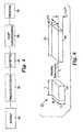
- Figure 4is a block diagram of a process according to an aspect of the present invention. The process forms a film with predetermined properties.
- the present inventionis applicable generally to a number of different films, materials and processes.
- the present inventionis believed to be particularly suited to fabrication of polymeric optical film where the visco-elastic characteristics of materials used in the film are exploited to control the amount, if any, of molecular orientation induced in the materials when the film is drawn during processing.
- consideration of the various properties of the materials used to produce optical filmsmay be exploited to improve the optical films.
- the improvementsinclude one or more of improved optical performance, increased resistance to fracture or tear, enhanced dimensional stability, better processability and the like.
- optical filmsmay be stretched or drawn according to the present invention.
- the filmsmay comprise single or multi-layer films. Suitable films are disclosed, for example, in U.S. Patent Nos. 5,699,188 ; 5,825,543 ; 5,882,574 ; 5,965,247 ; 6,096,375 ; and PCT Publication Nos. WO 95/17303 ; WO 96/19347 ; WO 99/36812 ; WO 99/36248 . These films can be drawn to stretch ratios in excess of 4. In some embodiments, the films are drawn to stretch ratios in excess of 5, in excess of 6, in excess of 6.5, or in excess of 7.
- Films made in accordance with the present inventionmay be useful for a wide variety of products including polarizers, reflective polarizers, dichroic polarizers, aligned reflective/dichroic polarizers, absorbing polarizers, retarders (including z-axis retarders).
- the filmsmay comprise the optical element itself or they can be used as a component in an optical element such as matched z-index polarizers used in beamsplitters for front and rear projection systems, or as a brightness enhancement film used in a display or microdisplay.
- the stretcher described below in accordance with the present inventionmay be used with a length orienter to make a mirror from a multi-layer optical film.
- FIG. 9A process for fabricating an optical film in accordance with one particular embodiment of the present invention will be described with reference to Figures 9 , 10 and 11 .
- Figures 9 , 10 and 11These figures illustrate a portion of an optical film.
- the depicted optical filmmay be described with reference to three mutually orthogonal axes TD, MD and ND.
- two orthogonal axes TD and MDare in the plane of the film (in-plane axes) and a third axis extends in the direction of the film thickness.
- FIG. 4is a block diagram of a process according to the present invention.
- the filmis supplied or provided to an apparatus for stretching the film.
- the processmay optionally include a preconditioning step 32.
- the filmis stretched in step 34.
- the filmmay optionally be post-conditioned in step 36.
- the filmis removed from the stretching apparatus in step 38.
- Figure 5illustrates a preferred embodiment of the invention.
- the processincludes the step of providing a film 40 to a stretching apparatus (see region 30').
- the filmmay be referred to with reference to a coordinate system of first and second orthogonal in-plane axes (e.g. machine direction MD and transverse direction TD) and a third mutually orthogonal axis in a thickness direction of the film (e.g. normal direction ND).
- the processincludes the steps of feeding the film 40 to a stretcher (see region 30'); stretching the film along the first in-plane axis of the film with the stretcher while allowing contraction of the film in the second in-plane axis and in the thickness direction of the film (see region 34'), with the stretching achieved by grasping edge portions of the film and moving the edge portions of the film, along predetermined paths 64 which diverge to create substantially the same proportional dimensional changes in the second in-plane axis of the film and in the thickness direction of the film.
- the processmay optionally include a preconditioning step (see region 32') such as providing an oven 54 or other apparatus.
- the preconditioning stepmay include a preheating zone (see region 42 of the film) and a heat soak zone (see region 44).
- the filmis stretched in region 34'. Edges of the film may be grasped by mechanical clips that are moved by rollers 62 in the direction of the arrows.
- paths 64are parabolic or substantially parabolic.
- the processincludes an optional post-conditioning step (see region 36').
- the filmmay be set in region 48 and quenched in region 50.
- a belt and rollersmay optionally be used to progress the film in this region.
- a cutmay be made at 58 and flash or unusable portion 56 may be discarded.
- the rapidly diverging edge portions 56are preferably severed from the stretched film 48 at a slitting point 58.
- release of the selvages from a continuous gripping mechanismcan be done continuously; however, release from discrete gripping mechanisms, such as tenter clips, should be done over discrete MD section of the film, e.g. all the material under any given clip is released at once. This discrete release mechanism may cause larger upsets in stress that may be felt by the drawing web upstream.
- a continuous selvage separation mechanismin the device, e.g. the "hot" slitting of the selvage from the central portion of a heated, drawn film.
- the slitting locationis preferably located near enough to the "gripline", e.g. the isolating takeaway point of first effective gripper contact, to minimize stress upsets upstream of that point If the film is slit before the gripping, instable takeaway can result, e.g. by film "snapback" along TD.
- the filmis thus preferably slit at or downstream of the gripline. Slitting is a fracture process and, as such, typically has a small but natural variation in spatial location. Thus it may be preferred to slit slightly downstream of the gripline to prevent any temporal variations in slitting from occurring upstream of the gripline.
- the film between the takeaway and boundary trajectorywill continue to stretch along TD. Since only this portion of the film is now drawing, it now draws at an amplified draw ratio relative to the boundary trajectory, creating further stress upsets that could propagate upstream, e.g. undesirable levels of machine direction tension propagating upstream.
- the slittingis preferably mobile and re-positionable so that it can vary with the changes in takeaway positions needed to accommodate variable final transverse draw direction ratio.
- An advantage of this type of slitting systemis that the draw ratio can be adjusted while maintaining the draw profile simply by moving the take-away slitting point 58.
- a variety of slitting techniquesmay be used included a heat razor, a hot wire, a laser, a focused beam of intense IR radiation or a focused jet of heated air.
- the heated jet of airthe air may be sufficiently hotter in the jet to blow a hole in the film, e.g. by heat softening, melting and controlled fracture under the jet.
- the heated jetmay merely soften a focused section of the film sufficiently to localize further drawing imposed by the still diverging boundary trajectories, thus causing eventual fracture downstream along this heated line through the action of continued film extension.
- the focused jet approachmay be preferred in some cases, especially when the exhaust air can be actively removed, e.g.
- a vacuum exhaustin a controlled fashion to prevent stray temperature currents from upsetting the uniformity of the drawing process.
- a concentric exhaust ring around the jet nozzlemay be used.
- an exhaust underneath the jet, e.g. on the other side of the film,may be used.
- the exhaustmay be further offset or supplemented downstream to further reduce stray flows upstream into the drawing zone.
- the processalso includes a removal portion in region 38'.
- a roller 65may be used to advance the film, but this may be eliminated.
- the roller 65is not used as it would contact the stretched film 52 with the attendant potential to damage the stretched film.
- Another cut 60may be made and unused portion 61 may be discarded.
Landscapes
- Engineering & Computer Science (AREA)
- Mechanical Engineering (AREA)
- Shaping By String And By Release Of Stress In Plastics And The Like (AREA)
- Polarising Elements (AREA)
- Liquid Crystal (AREA)
Abstract
Description
- The present invention relates to stretching films, particularly optical films and more particularly to optical films that are to be substantially uniaxially oriented. The present invention also comprises an apparatus suitable for stretching such films and the resultant films stretched by the apparatus.
- There are a variety of reasons to stretch films.
PCT WO 00/29197 - Stretching may enhance physical properties of crystalline plastic films.
U.S. Patent No. 2,998,772 discloses a machine for stretching film that includes circular discs that grasp edge portions of a film and stretch the film transverse to a machine direction of the film. Figure 1 illustrates a conventional tenter drawing process that stretches continuously fed films transversely to the direction of film travel. The film is gripped at bothedges 2 by some gripping means, typically by tenter clips. The tenter clips are connected to tenter chains that ride along linearly diverging tenter tracks or rails. This arrangement propels the film forward in a machine direction of film travel and stretches the film. Thus aninitial shape 4 in the film may be stretched to theshape 6.- Tenter apparatus are described in
U.S. Patent Nos. 2,618,012 ,3,502,766 ,3,890,421 ,4,330,499 ;4,525,317 and4,853,602 . Conventional tenters suffer many drawbacks. The angle of divergence in conventional tenters is typically small, usually less than 10 degrees. Boundary trajectories return to a parallel, or nearly parallel, state prior to quenching the polymeric film and slitting. Referring toFigure 2 , theunstretched portion 4 of the film shown inFigure 1 may have dimensions T, W and L. After the film is stretched by a factor of lambda (7), the dimensions of that portion of film have changed to those shown onportion 6. This is not uniaxial stretch as described in greater detail below. - As used herein, the ratio of the final T' to initial thickness of the film T (see
Figure 10 ) may be defined as the normal direction draw ratio (NDDR). The machine direction draw ratio (MDDR) may be defined as the length of a portion of the film after stretching divided by the initial length of that portion. For illustrative purposes only, see Y'/Y inFigure 11 . The transverse direction draw ratio (TDDR) may be defined as the width of a portion of the film after stretching divided by the initial width of that portion. For illustrative purposes only, see X0/X inFigure 9 . - The NDDR is roughly the reciprocal of the TDDR in a conventional tenter, while the MDDR is essentially unchanged. This asymmetry in MDDR and NDDR draw causes differences in the various molecular, mechanical and optical properties of the film above and beyond the differences in properties between these directions and the stretch direction (TD). Illustrative examples of such properties include the crystal orientation and morphology, thermal and hygroscopic expansions, the small strain anisotropic mechanical compliances, tear resistance, creep resistance, shrinkage, the refractive indices and absorption coefficients at various wavelengths.
U.S. Patent No. 4,862,564 discloses an apparatus for stretching a thermoplastic material web. The device includes an exponential or other curvilinear stretching profile. The apparatus provides a constant rate of stretch to the web, as opposed to the sharp peak and varying rate of stretch provided with conventional straight course tenter apparatus.- Uniaxially drawn films have superior performance to simply monoaxially drawn films. For example, uniaxially drawn films are more easily fibrillated or tom along the stretch direction (TD). In optical applications, matching the MD and ND indices of refraction is often advantageous. For example,
U.S. Patent Nos. 5,882,774 ;5,962,114 ; and5,965,247 (Jonza , et. al.) disclose materials with matched indexes of refraction for improved off-normal angle performance in brightness enhancement applications of multilayer reflective polarizers. Figure 3 illustrates a known batch technique for stretching a multilayer film suitable for use as a component in an optical device such as a polarizer. The flat, initial film 3 is stretched uniaxially in the direction of the arrows. The central portion necks down so that two edges of the film are no longer parallel after the stretching process. Much of thestretched film 5 is unusable as an optical component. Only a relatively smallcentral portion 9 of the film is suitable for use in an optical component such as a polarizer. The yield and usable part size from this process are small.- Japanese Unexamined Patent Publication
Hei 5-11114 - A conventional method for attempting to make a uniaxially drawn film is to use a length orienter (L.O.) that draws the film longitudinally in MD across at least one span between rollers of differing speed. The MDDR imparted along this span or draw gap is essentially the ratio of the speed of the downstream roll to the upstream roll. Because the film freely spans the rollers without edge constraints, the film can neck down in width as well as thin in caliper as it draws. Thus the TDDR can be reduced substantially below unity and can possibly be made to equal the NDDR. The method is fraught with difficulties and limitations. One disadvantage is the limitation on part size. An initial web of given width is reduced in width by a factor of the square root of the reciprocal of MDDR. Thus a final film made with an L.O. has a substantially reduced width. When contrasted to a film made by a tenter, which increases the width by roughly the TDDR (excluding edge losses from gripping), the L.O. under uniaxial conditions reduces the possible part size substantially.
- Stretching longitudinally tends to amplify machine direction propagated caliper imperfections such as die lines. In order to achieve a high degree of uniaxial character, the L.O. needs a long span relative to the film initial width. Practically, this requires a large device and long film spans that may be hard to control.
- Japanese Unexamined Patent Publication
Hei 6-34815 - In Japanese Unexamined Patent Publication
Hei-150115 - There have been many attempts to draw films in a uniaxial fashion. Japanese Unexamined Patent Publication Nos.
Hei 5-288931 5-288932 6-27321 6-34815 (H. Field - Japanese Unexamined Patent Publications,
Hei 5-241021 6-51116 6-51119 - Japanese Unexamined Patent Publications,
Hei 5-11113 U.S. Patent No. 4,349,500 (Yazawa , et. al.) discloses a film fed between two rotating disks or wheels. The film is gripped by two continuous belts. The film and the disks all lie in the same plane. The film stretches transversely between the counter rotating disks as its edges follow the diverging circumferential edges of the disks. The divergence angle of the draw becomes large, and the MD velocity of the film slows by the cosine of this divergence angle. The belt speed remains constant. In this manner, the output velocity is reduced from the input velocity of the film. The film is released from its gripping belts and the film is taken up at the slower MD velocity.- The method discloses the adjustment of the separation distance between the centers of rotation of the disks and the size af the disks. One disadvantage of this method, discussed in
U.S. Patent No. 5,826,314 , is the difficulty of maintaining good gripping of the film with the belt system. This would be particularly challenging in the stretching of films that develop high levels of drawing stress, e.g. polyesters drawn near their glass transition temperatures. It is believed that many materials used in this process would acquire a wrinkle or a non-uniaxially drawn permanent set using this method. For example, polyesters monoaxially drawn near their glass transitions while holding their MD lengths fixed may wrinkle rather than snap back in-plane when the final width is reduced in a succeeding step towards that anticipated for the substantially uniaxial case. Wrinkling also can occur when the MD reduction is applied too late in the TD drawing step. - Swenson
U.S. Patent No. 5,043,036 describes a canted wheel film drawing apparatus. Here the disks are no longer in-plane with the film and thus the sheet is stretched between out-of-plane boundary trajectories defined by the circumferences of the canted wheels. The method is described as a means of stretching films comprising elastomeric layers. As pointed out inU.S. Patent No. 3,807,004 , due to the developing MD tension along the progress of the draw, stretching between such out-of-plane curved surfaces causes the film surface to become saddle shaped. The central portion of the film straightens out as it is not directly held, as is the film at the boundary trajectories, and thus it draws along a different path than the edges. This non-uniform drawing can result in significant caliper and property variations across the web, and is a major disadvantage for drawing films along boundary trajectories that move out-of-plane. U.S. Patent No. 3,807,004 described a variety of methods for partially dealing with the saddle formation. Profiling the initial film thickness or temperature distribution is suggested as a means to uniform caliper, although property variations due to different drawing histories would remain. Alternatively, a support device could force the film in the central portion to conform to the curved out-of-plane trajectory. Friction and concomitant damage to the film surface might be reduced by various methods including an air cushion. Saddling also manifests in various operations with the aforementioned disk orienter as described inU.S. Patent No. 4,434,128 . A convex guide surface is used to counter the saddling. Damage to the film surface from the application of such methods is another disadvantage to the method. In particular, films used in optical applications are particularly sensitive to surface defects as may be caused by scuffling and other contact-related defects.- The present invention comprises processes for stretching film to provide desirable properties (e.g. optical properties), films stretched according to such processes and apparatus for stretching films. In preferred embodiments, the invention addresses shortcomings of the prior art such as excessive thickness deviation across the width of desired use of the final film, excessive anisotropic property deviation from fiber symmetry across the width of desired use of the final film, wrinkles and other non-flat imperfections in the final film, and surface contacting that can cause surface damage to the final film.
- In one aspect, the present invention includes a process for forming an optical film with predetermined optical properties, including the steps of providing a multilayer film having alternating layers of polymeric materials with predetermined optical properties, such that the film is defined in reference to a coordinate system of first and second orthogonal in-plane axes and a third mutually orthogonal axis in a thickness direction of the film; feeding the multilayer film to a stretcher; stretching the film along the first in-plane axis of the film with the stretcher while allowing contraction of the film in the second in-plane axis and in the thickness direction of the film, with the stretching achieved by grasping edge portions of the film and moving the edge portions of the film along predetermined paths which diverge to create substantially the same proportional dimensional changes in the second in-plane axis of the film and in the thickness direction of the film.
- In one embodiment, the predetermined paths are shaped so as to create substantially the same proportional dimensional changes in the second in-plane axis of the film and in the thickness direction of the film. In a preferred embodiment, at least one of the edge portions of the film is moved along a predetermined path that is substantially parabolic.
- In a different embodiment, the speed of the edge of the film is controlled to create substantially the same proportional dimensional changes in the second in-plane axis of the film and in the thickness direction of the film.
- In another embodiment, at least one of the edge portions of the film is moved along a predetermined path at a substantially constant speed.
- In a preferred embodiment, the process is a continuous process and the film is fed continuously to the stretcher. The film may be fed continuously to the stretcher from a roll, or the film may be extruded or coextruded in-line with the stretcher.
- In another embodiment, the strain rate along the stretch direction of the first in-plane axis is not constant during at least a portion of the stretch.
- Preferably, the proportional dimensional changes in the second in-plane axis of the film and in the thickness direction of the film are substantially the same throughout substantially all of the draw history.
- In another embodiment, the edge portions of the film move along predetermined paths that lie substantially within a plane defined by the first and second in-plane axes.
- In yet another embodiment, the edge portions of the film move along a predetermined path that is three-dimensional.
- Preferably, the edge portions of the film move along predetermined paths that are substantially symmetrical about a center axis.
- More preferably, the film has first and second major surfaces and the film is stretched without physically contacting the first and second major surfaces of the film except at the edge portions of the film.
- In another aspect, the present invention includes a process for forming film with predetermined properties, including the steps of providing a film that is defined in reference to a coordinate system of first and second orthogonal in-plane axes and a third mutually orthogonal axis in a thickness direction of the film; feeding the film to a stretcher; stretching the film along the first in-plane axis of the film with the stretcher while allowing contraction of the film in the second in-plane axis and in the thickness direction of the film, with the stretching accomplished by grasping edge portions of the film and moving edge portions of the film along predetermined paths that are shaped to create substantially the same proportional dimensional changes in the second in-plane axis of the film and in the thickness direction of the film throughout substantially all of the stretching step.
- In another aspect, the present invention includes a process for forming film with predetermined properties, including the steps of providing a film that is defined in reference to a coordinate system similar to that described above; feeding the film to a stretcher in a direction of travel of the film; stretching the film along the first in-plane axis of the film with the stretcher while allowing contraction of the film in the second in-plane axis and in the thickness direction of the film, with the stretching accomplished by grasping edge portions of the film and moving the edge portions of the film along substantially parabolic paths that diverge.
- In a preferred embodiment, the present invention includes a continuous process for forming film with predetermined properties, including the steps of providing a film that is defined in reference to a coordinate system similar to that described above; continuously feeding the film to a stretcher in a direction of travel of the film; stretching the film along the first in-plane axis of the film with the stretcher while allowing contraction of the film in the second in-plane axis and in the thickness direction of the film, with the stretching accomplished by grasping edge portions of the film and moving the edge portions of the film along predetermined paths that diverge in such a way that the strain rate in the direction of the first in-plane axis is not constant during at least a portion of the stretching step.
- In another aspect, the present invention includes a roll of optical film with predetermined optical properties defined in reference to a coordinate system of first and second orthogonal in-plane axes and a third mutually orthogonal axis in a thickness direction of the film, such that the roll of optical film is constructed by the process of continuously feeding a roll of film to a stretcher and continuously stretching the film along the first in-plane axis of the film with the stretcher while allowing contraction of the film in the second in-plane axis and in the thickness direction of the film to create substantially the same proportional dimensional changes in the second in-plane axis of the film and in the thickness direction of the film.
- Preferably, the roll of optical film is a multilayer optical film having alternating layers of polymeric materials having predetermined optical properties.
- More preferably, the roll of optical film has portions suitable for being incorporated into a polarizer. Even more preferably, the polarizer may be a reflective polarizer.
- Preferably, the roll of film is constructed by the process of stretching the film so that substantially the same proportional dimensional changes in the second in-plane axis of the film and in the thickness direction of the film are created throughout substantially all of the stretching process.
- In yet another aspect, the present invention is a stretcher for continuously processing film, including a means for receiving a continuous supply of film having predetermined properties, with the film being defined in reference to a coordinate system as described above; clamping means for grasping edge portions of the film; and stretching means for continuously moving the clamping means along predetermined paths that diverge so that the film is stretched along the transverse direction while allowing contraction of the film in the machine direction and the thickness direction, with the predetermined paths having shapes that are selected to create substantially the same proportional dimensional changes in the machine direction of the film and in the thickness direction of the film to impart predetermined optical properties into the film.
- The stretcher preferably includes a means for receiving a supply of the film which includes a means for receiving the film from a roll of said film.
- The stretcher also preferably includes take away means for removing the stretched film from the stretcher. In a preferred embodiment, the take away means includes means for severing the stretched film from rapidly diverging edge portions of the film and moving the stretched portion out of the stretcher.
- The following aspects are preferred embodiments of the invention.
- 1. A method of processing a film, the method comprising:
- conveying a film within a stretcher along a machine direction while holding opposing edge portions of the film;
- stretching the film within a stretching region of the stretcher by moving the opposing edge portions along diverging paths to form a stretched region of the film;
- releasing the opposing edge portions of the stretched region of the film; and
- grasping the stretched region of the film at opposing take-away regions positioned inside each of the opposing edge portions prior to releasing the opposing edge portions to take the stretched film away from stretching region.
- 2. The method of
aspect 1, wherein the step of grasping the stretched region of the film further comprises slitting the stretched region of the film between the opposing edge regions and the opposing take-away regions to form selvages that continue along the diverging paths. - 3. The method of
aspect 1, wherein, after grasping the stretched region of the film at opposing take-away regions, the portion of the stretched region of the film between the opposing take-away regions is not subject to substantial additional stretching. - 4. The method of
aspect 1, wherein stretching the film within a stretching region of the stretcher comprising stretching the film within the stretching region of the stretcher by moving the opposing edge portions along diverging, substantially parabolic paths to form the stretched region of the film. - 5. The method of
aspect 4, wherein the diverging, substantially parabolic paths have a functional form:
wherein an x-axis is defined in a plane of the film and orthogonal to the machine direction with x=0 at a center axis of the film, a y-axis is defined in the plane of the film and along the machine direction with y=0 where stretching of the film commences within the stretcher, and x0 is a distance of the edge portions from the center axis of the film when y=0. - 6. The method of
aspect 4, wherein at least a portion of the diverging, substantially parabolic paths have a functional form:
wherein an x-axis is defined in a plane of the multilayer film and orthogonal to the machine direction with x=0 at a center axis of the multilayer film, a y-axis is defined in the plane of the multilayer film and along the machine direction with y=0 where stretching of the multilayer film commences within the stretcher, c is any number, and x1 is a distance of the edge portions from the center axis of the multilayer film when y=0. - 7. The method of
aspect 1, further comprising providing the film in a continuous manner to the stretcher. - 8. The method of aspect 7, wherein providing the film comprises providing the film in a continuous manner to the stretcher from a roll of film.
- 9. The method of aspect 7, wherein providing the film comprises extruding or coextruding the film in-line with the stretcher.
- 10. The method of
aspect 1, wherein stretching the film within a stretching region of the stretcher comprising stretching the film within the stretching region of the stretcher by moving the opposing edge portions along diverging, substantially parabolic paths to form the stretched region of the film, wherein the film has an initial thickness and initial width when conveyed into the stretcher and the stretched region of the film has a stretched thickness and a stretched width; and
wherein, after stretching the film to a ratio of stretched width/initial width defined as λ, a ratio of stretched thickness/initial thickness is approximately λ-1/2. - 11. A method of processing a film, the method comprising:
- conveying a film within a stretcher along a machine direction while holding opposing edge portions of the film;
- stretching the film within a stretching region of the stretcher by moving the opposing edge portions along diverging paths to form a stretched film;
- slitting the stretched film between the opposing edge regions and the opposing take-away regions to form selvages that continue along the diverging paths while a remainder of the stretched film is conveyed in the machine direction; and
- releasing the opposing edge portions of the stretched film.
- 12. The method of aspect 11, further comprising grasping the film at opposing take-away regions inside each of the opposing edge portions prior toslitting the stretched film.
- 13. The method of aspect 11, further comprising grasping the film at opposing take-away regions inside each of the opposing edge portions while slitting the stretched film.
- 14. The method of aspect 11,, wherein stretching the film within a stretching region of the stretcher comprising stretching the film within the stretching region of the stretcher by moving the opposing edge portions along diverging, substantially parabolic paths to form the stretched region of the film.
- 15. An apparatus for processing a film, the apparatus comprising:
- a conveyor comprising gripping members that hold opposing edge portions of the film and convey, under influence of a drive member, the film along a machine direction within a stretching region of the apparatus, wherein a portion of the conveyor is configured and arranged to provide diverging paths along which the gripping members move to stretch the film; and
- an isolated takeaway device that receives the film from the conveyor and comprising gripping members to grasp opposing takeaway regions of the film after a desired amount of stretching and convey the film in the machine direction.
- 16. The apparatus of aspect 15, wherein the isolated takeaway device is configured and arranged to convey the film without substantial stretching of the region of the film between the opposing take-away regions.
- 17. The apparatus of aspect 15, wherein the conveyor comprises a plurality of pathways with a plurality of the gripping members disposed to follow along each of the pathways.
- 18. The apparatus of aspect 15, further comprising a slitting member positioned within the apparatus to slit the stretched portion of the film between the opposing edge regions and the opposing takeaway regions to form selvages that continue along the diverging paths while a remainder of the stretched portion of the film is conveyed in the machine direction.
- 19. The apparatus of aspect 15, wherein the slitting member is configured and arranged to slit the stretched portion of the film after the takeaway device has grasped the opposing takeway regions.
- 20. The apparatus of aspect 15, wherein the diverging paths are substantially parabolic.
- 21. The apparatus of
aspect 20, wherein the diverging, substantially parabolic paths have a functional form:
wherein an x-axis is defined in a plane of the film and orthogonal to the machine direction with x=0 at a center axis of the film, a y-axis is defined in the plane of the film and along the machine direction with y=0 where stretching of the film commences within the stretcher, and x0 is a distance of the edge portions from the center axis of the film when y=0. - 22. The apparatus of
aspect 20, wherein, at least a portion of the diverging, substantially parabolic paths have a functional form:
wherein an x-axis is defined in a plane of the multilayer film and orthogonal to the machine direction with x=0 at a center axis of the multilayer film, a y-axis is defined in the plane of the multilayer film and along the machine direction with y=0 where stretching of the multilayer film commences within the stretcher, c is any number, and x1 is a distance of the edge portions from the center axis of the multilayer film when y=0. - 23. The apparatus of aspect 15, further comprising an extruder in-line with the conveyor, wherein the extruder is configured and arranged to provide the film to the conveyor.
- 24. An apparatus for processing a film, the apparatus comprising:
- conveying means for conveying a film along a machine direction within a stretching region of the apparatus, the conveying means comprising gripping means for holding opposing edge portions of the film, a portion of the conveying means providing diverging paths to stretch the film; and
- isolated takeaway means for grasping opposing takeaway regions and taking the film from the conveyor after a desired amount of stretching and conveying the film further along in the machine direction.
- 25. The apparatus of
aspect 24, further comprising slitting means for slitting a stretched portion of the film between the opposing edge regions and the opposing takeaway regions to form selvages. - 26. The method of
aspect 1, wherein a take-away speed of the film while the film is grasped at the opposing take-away regions is greater than a speed of the film in the stretching region. - The invention may be more completely understood in the following detailed description of various embodiment of the invention in connection with the accompanying drawings, in which:
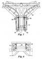
Figure 1 is a schematic top view of a prior art tenter apparatus used to stretch film;Figure 2 is a perspective view of a portion of film in the prior art process depicted inFigure 1 both before and after the stretching process;Figure 3 is a schematic illustration of a prior art batch process for drawing a multilayer optical film showing the film both before and after the stretch;Figure 4 is a block diagram showing steps according to one aspect of the present invention;Figure 5 is a schematic illustration of the stretching process according to a preferred embodiment of the present invention;Figure 6 is a perspective view of a portion of film in the process depicted inFigure 5 both before and after the stretching process;Figure 7 is a schematic top view of a portion of a stretching apparatus according to one aspect of the present invention;Figure 8 is an end view of the apparatus ofFigure 7 ;Figure 9 is a schematic view of a stretched film illustrating a coordinate axis showing a machine direction (MD), a normal direction (ND) a transverse direction, an initial width X, a stretched width XO and a boundary trajectory IBT;Figure 10 is a side view of a stretched film illustrating an initial thickness T, a final thickness T' a the normal direction ND;Figure 11 is a schematic view of a stretched film illustrating a coordinate axis showing a machine direction (MD), a normal direction (ND) a transverse direction (TD), an initial length Y, a stretched length Y' and a boundary trajectory IBT; andFigure 12 is a perspective view of a take away portion of an apparatus according to an aspect of the present invention.- The invention is amenable to various modifications and alternative forms. Specifics of the invention are shown in the drawings by way of example only. The intention is not to limit the invention to the particular embodiments described. Instead, the intention is to cover all modifications, equivalents, and alternatives falling within the spirit and scope of the invention as defined in the claims.
Figure 4 is a block diagram of a process according to an aspect of the present invention. The process forms a film with predetermined properties.- The present invention is applicable generally to a number of different films, materials and processes. The present invention is believed to be particularly suited to fabrication of polymeric optical film where the visco-elastic characteristics of materials used in the film are exploited to control the amount, if any, of molecular orientation induced in the materials when the film is drawn during processing. As described below, consideration of the various properties of the materials used to produce optical films may be exploited to improve the optical films. The improvements include one or more of improved optical performance, increased resistance to fracture or tear, enhanced dimensional stability, better processability and the like.
- A variety of optical films may be stretched or drawn according to the present invention. The films may comprise single or multi-layer films. Suitable films are disclosed, for example, in
U.S. Patent Nos. 5,699,188 ;5,825,543 ;5,882,574 ;5,965,247 ;6,096,375 ; andPCT Publication Nos. WO 95/17303 WO 96/19347 WO 99/36812 WO 99/36248 - Films made in accordance with the present invention may be useful for a wide variety of products including polarizers, reflective polarizers, dichroic polarizers, aligned reflective/dichroic polarizers, absorbing polarizers, retarders (including z-axis retarders). The films may comprise the optical element itself or they can be used as a component in an optical element such as matched z-index polarizers used in beamsplitters for front and rear projection systems, or as a brightness enhancement film used in a display or microdisplay. It should also be noted that the stretcher described below in accordance with the present invention may be used with a length orienter to make a mirror from a multi-layer optical film.
- A process for fabricating an optical film in accordance with one particular embodiment of the present invention will be described with reference to
Figures 9 ,10 and11 . These figures illustrate a portion of an optical film. The depicted optical film may be described with reference to three mutually orthogonal axes TD, MD and ND. In the illustrated embodiment, two orthogonal axes TD and MD are in the plane of the film (in-plane axes) and a third axis extends in the direction of the film thickness. Figure 4 is a block diagram of a process according to the present invention. Instep 30, the film is supplied or provided to an apparatus for stretching the film. The process may optionally include a preconditioning step 32. The film is stretched instep 34. The film may optionally be post-conditioned instep 36. The film is removed from the stretching apparatus instep 38.Figure 5 illustrates a preferred embodiment of the invention. The process includes the step of providing afilm 40 to a stretching apparatus (see region 30'). As shown inFigures 9 ,10 and11 , the film may be referred to with reference to a coordinate system of first and second orthogonal in-plane axes (e.g. machine direction MD and transverse direction TD) and a third mutually orthogonal axis in a thickness direction of the film (e.g. normal direction ND).- The process includes the steps of feeding the
film 40 to a stretcher (see region 30'); stretching the film along the first in-plane axis of the film with the stretcher while allowing contraction of the film in the second in-plane axis and in the thickness direction of the film (see region 34'), with the stretching achieved by grasping edge portions of the film and moving the edge portions of the film, alongpredetermined paths 64 which diverge to create substantially the same proportional dimensional changes in the second in-plane axis of the film and in the thickness direction of the film. - The process may optionally include a preconditioning step (see
region 32') such as providing anoven 54 or other apparatus. The preconditioning step may include a preheating zone (seeregion 42 of the film) and a heat soak zone (see region 44). - The film is stretched in region 34'. Edges of the film may be grasped by mechanical clips that are moved by
rollers 62 in the direction of the arrows. In a preferred embodiment,paths 64 are parabolic or substantially parabolic. - The process includes an optional post-conditioning step (see
region 36'). For example, the film may be set inregion 48 and quenched inregion 50. A belt and rollers may optionally be used to progress the film in this region. A cut may be made at 58 and flash orunusable portion 56 may be discarded. - To maintain a substantially uniaxial draw throughout substantially all of the draw history (as shown in
Fig. 5 ), at the end of the transverse stretch, the rapidly divergingedge portions 56 are preferably severed from the stretchedfilm 48 at aslitting point 58. - Release of the selvages from a continuous gripping mechanism can be done continuously; however, release from discrete gripping mechanisms, such as tenter clips, should be done over discrete MD section of the film, e.g. all the material under any given clip is released at once. This discrete release mechanism may cause larger upsets in stress that may be felt by the drawing web upstream. In order to assist the action of the isolating takeaway device, it is preferred to use a continuous selvage separation mechanism in the device, e.g. the "hot" slitting of the selvage from the central portion of a heated, drawn film.
- The slitting location is preferably located near enough to the "gripline", e.g. the isolating takeaway point of first effective gripper contact, to minimize stress upsets upstream of that point If the film is slit before the gripping, instable takeaway can result, e.g. by film "snapback" along TD. The film is thus preferably slit at or downstream of the gripline. Slitting is a fracture process and, as such, typically has a small but natural variation in spatial location. Thus it may be preferred to slit slightly downstream of the gripline to prevent any temporal variations in slitting from occurring upstream of the gripline. If the film is slit substantially downstream from the gripline, the film between the takeaway and boundary trajectory will continue to stretch along TD. Since only this portion of the film is now drawing, it now draws at an amplified draw ratio relative to the boundary trajectory, creating further stress upsets that could propagate upstream, e.g. undesirable levels of machine direction tension propagating upstream.
- The slitting is preferably mobile and re-positionable so that it can vary with the changes in takeaway positions needed to accommodate variable final transverse draw direction ratio. An advantage of this type of slitting system is that the draw ratio can be adjusted while maintaining the draw profile simply by moving the take-away
slitting point 58. - A variety of slitting techniques may be used included a heat razor, a hot wire, a laser, a focused beam of intense IR radiation or a focused jet of heated air. In the case of the heated jet of air, the air may be sufficiently hotter in the jet to blow a hole in the film, e.g. by heat softening, melting and controlled fracture under the jet. Alternatively, the heated jet may merely soften a focused section of the film sufficiently to localize further drawing imposed by the still diverging boundary trajectories, thus causing eventual fracture downstream along this heated line through the action of continued film extension. The focused jet approach may be preferred in some cases, especially when the exhaust air can be actively removed, e.g. by a vacuum exhaust, in a controlled fashion to prevent stray temperature currents from upsetting the uniformity of the drawing process. For example, a concentric exhaust ring around the jet nozzle may be used. Alternatively, an exhaust underneath the jet, e.g. on the other side of the film, may be used. The exhaust may be further offset or supplemented downstream to further reduce stray flows upstream into the drawing zone.
- The process also includes a removal portion in
region 38'. Optionally aroller 65 may be used to advance the film, but this may be eliminated. Preferably theroller 65 is not used as it would contact the stretchedfilm 52 with the attendant potential to damage the stretched film. Another cut 60 may be made andunused portion 61 may be discarded. Figure 6 helps illustrate what is meant in this application when it is said that the process "creates substantially the same proportional dimensional changes in the second in-plane axis of the film and in the thickness direction of the film". Threedimensional element 24 represents an unstretched portion of film (see e.g.Figures 5 and6 ) with dimensions T, W and L. Threedimensional element 26 representselement 24 after it has been stretched a length lambda. As can be seen inFigure 6 , the thickness and width have been reduced by the same proportional dimensional changes.Figure 6 represents a uniaxial stretch, as opposed, for example, to the non-uniaxial stretch shown inFigure 2 .- The present invention is not limited to perfect uniaxial stretching. Instead, the present invention includes processes, apparatus and films that are "substantially" uniaxially stretched. The following discussion and observations are provided to define what is within the scope of the present invention.
- "Substantially" uniaxially drawn films preferably possess fiber symmetry in which the properties in MD and ND are similar within a given material layer (as films comprising multiple layers may not themselves possess fiber symmetry due to the layered natured of the film composite). This may exist in an elastic material when two of the draw ratios are equal. When one of the directions, e.g. TD, is stretched, then the other two directions, e.g. MD and ND, preferably have equal draw ratios. Assuming volume conservation, the MDDR and NDDR both should approach the square root of the reciprocal of the TDDR. Films drawn in a conventional tenter are not substantially uniaxially drawn even though they have been physically drawn in only one direction (so-called "monoaxial" drawing) because the boundary constraints of the process impart differences between MDDR and NDDR.
- The present invention is also not limited to those processes that stretch film under uniaxial conditions throughout the entire history of the stretch or draw. In a preferred embodiment, the present invention addresses the inadequacy of prior art processes (e.g. the disk orienters) to provide the substantially uniaxial constraint on machine direction draw ratio (MDDR) and transverse direction draw ratio (TDDR) throughout the entire history of the draw. The failure of the prior art to provide the uniaxial condition throughout the draw is a cause of wrinkling and other out-of-plane defects in the final film.
- In a preferred embodiment, the present invention provides a process in which a substantially uniaxial draw is provided via the boundary trajectories throughout the drawing step. More preferably, the process provides this history dependence while maintaining the film in-plane. However, the stretching step need not be performed within a substantially planar region (as depicted in
Figure 5 ). As discussed in more detail below, it is within the present invention to provide a boundary trajectory of the film that is three dimensional and substantially non-planar. - Preferably the present invention maintains the deviation from a uniaxial draw within certain tolerances throughout the various portions of the drawing step. Optionally, the present invention may maintain these conditions while deforming a portion of the film out-of-plane in an initial portion of the draw, but return the film in-plane during a final portion of the draw.
- In a uniaxial transverse draw maintained throughout the entire history of the draw, the instantaneous MDDR equals the square root of the reciprocal of the TDDR. As discussed above in conjunction with a preferred embodiment of the present invention, the film may be drawn out-of-plane using out-of-plane boundary trajectories, i.e. boundary trajectories that do not lie in a single Euclidean plane. There are innumerable, but nevertheless particular, boundary trajectories meeting relational requirements of this preferred embodiment of the present invention, so that a substantially uniaxial draw history may be maintained using out-of-plane boundary trajectories.
- The boundaries may be symmetrical, forming mirror images through a central plane, e.g. a plane comprising the initial center point between the boundary trajectories, the initial direction of film travel and the initial normal to the unstretched film surface. In this preferred embodiment the film may be drawn between the boundary trajectories along a cylindrical space manifold formed by the set of line segments of shortest distance between the two opposing boundary trajectories as one travels along these boundary trajectories at equal rates of speed from similar initial positions, i.e., colinear with each other and the initial center point. The trace of this ideal manifold on the central plane thus traces out the path of the film center for an ideal draw. The ratio of the distance along this manifold from the boundary trajectory to this central trace on the central plane to the original distance from the start of the boundary trajectory to the initial center point is the instantaneous nominal TDDR across the film spanning the boundary trajectories, i.e. the ratios of the half-distances between the current opposing points on the boundary trajectories and the half-distances between the initial positions of the opposing points on the boundary trajectories. As two opposing points move at constant and identical speeds along the opposing boundary trajectories, the corresponding center point on the central trace changes speed as measured along the arc of the central trace, i.e. the curvilinear MD. In particular, the central trace changes in proportion with the projection of the unit tangent of the boundary trajectory on the unit tangent of the central trace.
- Uniaxial draw may be maintained along the entire history of the draw as long as the speed of the central point reduces at every point along the central trace from its initial speed by a factor of exactly the square root of the reciprocal of the instantaneous TDDR measured between the corresponding opposing points on the opposing boundary trajectories. This is the uniaxial condition when viewing the instantaneous MDDR of a differential film arc along the idealized central trace. The uniaxial condition may be achieved by controlling the ratio of the instantaneous rate of change of arc length along the central trace to the instantaneous rate of change of arc length at a corresponding opposing point on a boundary trajectory, i.e. the curvilinear MDDR By maintaining this constraint, suitable boundary trajectories within the general class of three dimensional space curves may be found and specified within the context of this preferred embodiment of the present invention.
- Preferably, the film is drawn in plane such as shown in
Figure 5 . This avoids the problems of maintaining the central portions of the film to the idealized space manifold of draw. The design of the boundary trajectories is also simplified because the in-plane constraint reduces the number of variables. There is one pair of mirror image opposing boundary trajectories that maintains the uniaxial condition throughout the process of the draw. The design of the boundary trajectory may proceed by considering the instantaneous in-plane draw ratios MDDR and TDDR rather than the MDDR or MD speed as defined along the curvilinear central trace. The result is a pair of mirror symmetric in-plane parabolic trajectories diverging away from the in-plane MD centerline between them. The parabola may be portrayed by first defining the TD as the "x" direction and the MD as the "y" direction. The MD centerline between the opposing bounding parabolas may be taken as the y coordinate axis. The coordinate origin may be chosen as the initial centerpoint of the central trace between the parabolic trajectories and the left and right bounding parabolas are chosen to start at minus and plus X0, respectively, where y=0. The right bounding parabolic trajectory, for positive y values, that embodies this preferred embodiment of the invention is (equation 1):
The left bounding parabolic trajectory is obtained by multiplying the left-band side of theabove equation 1 by minus unity. - The parabolic trajectory of
equation 1 provides the uniaxial condition. As such it represents the in-plane drawing state in which MD tension should be negligible. In order to obtain good yield and property uniformity across the usable width of the final film, the principal axes of molecular orientation and of the resulting properties as induced by the draw preferably remain nearly constant. In this case, straight lines drawn along TD, the principal draw direction, remain substantially straight after drawing. In tenter processing of biaxially oriented films, this is typically not the case. - It should be again noted that the present invention is not limited to perfectly uniaxially drawn films. In practice, nearly or "substantially" uniaxially drawn films are sufficient to make components of sufficient desired properties. Often, the uniformity of such films is more important than the precise manifestation of uniaxial character. A discrepancy in uniaxial character in properties such as refractive index is tolerable in many applications. For example, the off-angle characteristics of reflective polarizers used in liquid crystalline display applications is strongly impacted by the difference in the MD and ND indices of refraction when TD is the principal mono-axial draw direction. An index difference in MD and ND at 633 nm of 0.08 may be acceptable in some applications. A difference of 0.04 is allowable in others. In more stringent applications, a difference of 0.02 or less is preferred. Thus preferred embodiments of films according to the present invention include the class of nearly or substantially uniaxially drawn films, processes for creating such substantially uniaxially drawn films and apparatus for creating such substantially uniaxially drawn films.
- A preferred method for calculating trajectories within a specified envelope of nearly or substantially uniaxial character is discussed. The method determines the "right" boundary trajectory directly, and the "left" boundary trajectory is taken as a mirror image. First, the envelope constraint is set by defining an instantaneous functional relationship between TDDR measured between the opposing boundary trajectories and the MDDR defined as the cosine of the non-negative divergence angle of those boundary trajectories, over a chosen range of TDDR. Next, the geometry of the problem is defined as described in the discussion of the parabolic trajectories. X1 is defined as the initial half width between the boundary trajectories and ratio (x/x1) is identified as the instantaneous TDDR, where x is the current x position of an opposing point on the boundary trajectory. Next, the instantaneous functional relationship between the TDDR and MDDR is converted to a relationship between TDDR and the divergence angle. Next, the boundary trajectory is constrained to satisfy the differential equation, equation 2:

where tan(θ) is the tangent of the divergence angle θ, and y is the y coordinate of the current position of the opposing point on the right boundary trajectory corresponding to the given x coordinate. Next, the differential equation may be solved, e.g. by integrating 1/tan(θ) along the history of the TDDR, (x/x1), from unity to the maximum desired value to obtain the complete coordinate set {(x,y)} of the right boundary trajectory, either analytically or numerically. The divergence angle is the non-nagativer, smallest angle made between the direction of travel of the centerline of the film and the instantaneous boundary trajectory at (x,y). In the symmetric, in-plane case ofequation 2, the travel of the center line is along MD, e.g. the divergence angle is zero, when the boundary trajectories are parallel to MD, as is nearly the case in a conventional tenter. - The method of a preferred embodiment of the present invention is illustrated by way of the parabolic trajectory example. First the envelope is chosen as the uniaxial constraint. The TDDR is shown to equal the square of the reciprocal of the cosine of the divergence angle. The TDDR is equal to the square of the tangent of the divergence angle plus unity. This allows direct substitution of the left-hand side of the equation by a function of TDDR only. The equation can then be analytically integrated to discover the result,
equation 1. - In another preferred embodiment, let the extent of uniaxial character U, be defined by a simple ratio according to equation 3:

The state U=1 meets the uniaxial condition. States of U between zero and unity represent intermediate states in which some level of MD tension will develop. States near unity are nearly or substantially uniaxial. States ofU greater than unity represent various levels of over-relaxing. These over-relaxed states effect an MD compression from the boundary edge. If the level of MD compression is sufficient for the geometry and material stiffness, the film will buckle or wrinkle. In some embodiments, it is preferred that the product, MDDR·(TDDR)1/2, is at least 0.5 over the coarse of the stretching, corresponding to an overfeed of 100% or less. - The following discussion is also useful in understanding what is meant by a preferred "substantially" uniaxially drawn film in the context of the present invention. One class of preferred curves within an envelope of final film acceptability are those that maintain the extent of uniaxial character above a desired threshold value throughout the course of the draw, since in many final film applications, a final extent of uniaxial character less than unity can provide acceptable performance. For example, the extent of uniaxial character of 0.85 is sufficient in many cases to provide an index of refraction difference between the MD and ND directions in polyester systems comprising polyethylene naphthalate of 0.02 or less at 633 nm for mono-axially transverse drawn films. In some embodiments, the extent of uniaxial character can be at least 0.9 or 0.95 or higher. For some polyester systems, such as polyethylene terephthalate, a lower U value of 0.80 or even 0.75 may be acceptable, e.g. because of lower intrinsic differences in refractive indices in non-substantially uniaxially drawn films. When a specific value af U is chosen, Equation 3 provides a specific relationship between MDDR and TDDR which, when coupled with the aforementioned algorithm or method, specifies a broader class of boundary trajectories that also includes the parabolic trajectories as a limiting case when U approaches unity. Trajectories that exhibit values ofU below unity for at least a final portion of the draw are referred to herein as sub-parabolic trajectories.
- The condition of constant U less than unity may be approximated by a preferred class of in-plane "sub-parabolic" trajectories in which the parabolic trajectory of
equation 1 is used with smaller initial effective web widths. If x1 is still taken as the true effective half width of the drawable central portion of the web after effective gripping (i.e. the initial width minus the selvages held by the grippers which is the initial half distance between opposing boundary trajectories), then this class of trajectories is described by equation 4:
where "c" is a positive offset distance. This class of trajectories is a preferred approximation to constant U for TDDR under 8. - Still another class of boundary trajectories may be preferred in suppressing residual wrinkles. Because the uniaxial condition in the absence of shear provides a principal MD stress of zero, it is anticipated, using finite strain analysis, that the principal MD stress will actually go into slight compression under these conditions. Using finite strain analysis and a Neo-Hookean elastic solid constitutive equation, it is discovered that a suitable criterion for preventing compressive stresses may optionally be given by equation 5:

- The class of trajectories described above are illustrative and should not be construed as limiting. A host of trajectory classes are considered to lie within the scope of the present invention. The present invention preferably encompasses all nearly uniaxial boundary trajectories comprising a minimum value of U of about 0.70, more preferably approximately 0.75, still more preferably about 0.80 and even more preferably about 0.85. The minimum U constraint may be applied over a final portion of the draw defined by a critical TDDR preferably of about 2.5, still more preferably about 2.0 and more preferably about 1.5. In some embodiments, the critical TDDR can be 4 or 5. Above a critical TDDR, certain materials, e.g. certain monolithic and multilayer films comprising orientable and birefringent polyesters, may begin to lose their elasticity or capability of snap back, e.g. because of the development of structure such as strain-induced crystallinity. The TDDR may coincide with a variety of material and process (e.g. temperature and strain rate) specific events such as the critical TDDR for the onset of strain-induced crystallization. The minimum value of U above such a critical TDDR could relate to an amount of non-uniaxial character set into the final film. As discussed above, it may be preferred to introduce a small level of MD tension into the film to suppress wrinkling. Preferably, the amount of such MD tension increases with decreasing U.
- It may be preferred to increase the tension as the draw proceeds. For example, a smaller value of U earlier in the draw may tend to set more non-uniaxial character into the final film. Thus it may be advantageous to combine the attribute of various trajectory classes into composite trajectories. For example, the parabolic trajectory may be preferred in the earlier portions of the draw, while the later portions of the draw may converge on a trajectory of the more expanded parabola of
equation 4 or the trajectory class ofequation 5. In another arrangement, U may be taken as a non-increasing function with TDDR, as opposed to a prior art disk orienter that decreases U with TDDR. - The parabolic trajectory assumes a uniform spatial drawing of the film. Good spatial uniformity of the film may be achieved with many polymeric systems with careful control of the crossweb and downweb caliper (thickness) distribution af the initial, undrawn film or web, coupled with the careful control of the temperature distribution at the start of and during the draw. For example, a uniform temperature distribution across the film initially and during draw on a film of initially uniform caliper should suffice in most cases. Many polymeric systems are particularly sensitive to non-uniformities and will draw in a non-uniform fashion if caliper and temperature uniformity are inadequate. For example, polypropylenes tend to "line draw" under mono-axial drawing. Certain polyesters, notably polyethylene naphthalate, are also very sensitive.
- The invention includes means for gripping the film, preferably the edges of the film. Preferably, the film is sandwiched between gripper faces on a mechanical clip assembly. The effective edge of the gripper face where the film is no longer effectively held defines the edge of the central portion of the film that will be drawn. This gripper edge defines a boundary edge for the drawing film. The motion of the gripper may also define a boundary trajectory that is, at least in part, responsible for the motion and drawing of the film (while other effects, e.g., downweb tension and take-up devices, may account for the rest of the motion and drawing.). Preferably, although not required, the gripper face edges are designed so that the center of the edge measured along one clip instantaneously follows the tangent of a chain riding along a rail or inside a channel cut into the rail. The boundary trajectory may also be defined by the rail when offset of the gripper edge face from the rail channel are included. In practice, the effective edge of the gripper face can be somewhat obscured by slight film slippage from or flow out from under the faces, but these deviations can be made small. Since the film is held by two sets of opposing grippers mounted on pairs of chains and rails, there are two opposing boundary trajectories. Preferably, these trajectories are mirror images about the MD center line of the drawing film.
- The rails are traditionally formed by a series of straight segments whose angle of divergence, e.g. the angle formed between the boundary trajectories and the direction of film travel (e.g. MD), may be adjusted. Curved trajectories have also been explored.
- The means for gripping the film according to the present invention may be discrete or continuous in nature.
Figures 7 and 8 illustrate details of a preferred embodiment of an apparatus for stretching films according to an aspect of the present invention. The gripping means comprise a series of tenter clips 70 that afford overall flexibility via segmentation. Thediscrete clips 70 are closely packed and attached to a flexible structure such as a chain. The flexible structure rides along or in channels along the trajectory control device, such as a rail. Strategically placed cams and carn surfaces open and close the tenter clips at desired points. The clip and chain assembly may optionally ride on wheels or bearings or the like. Alternatively, the continuous gripping mechanism may comprise a flexible and continuous mechanism, such as a belt or tread. The flexible and continuous mechanism may nest or ride in a groove or a channel. Alternatively, a variety of other opposing, multiple belt methods, e.g. as described inU.S. Patent No. 5,517,737 or in European patent Application0236171 A1 may be used. These may ride in grooves, or ride over bearings or some other means of underlying support allowing motion of the flexible continuous mechanism. - Preferred continuous gripping mechanisms provide the advantage of continuously following the changing boundary trajectories along every portion of the boundary edge. Segmented, discrete gripping systems are within the present invention and tend to only approximate the boundary trajectory along portions of the film at the boundary edges. For example, a tenter clip has a straight clip face edge. The clip is mounted so that the center of this clip face edge remains tangent to the boundary trajectory, e.g. tangent to the tenter rail, throughout the course of travel and draw. This means that the flm gripped at the center does follow the boundary trajectory; however, the rest of the film gripped along the rest of the clip is constrained to a path deviating from the boundary trajectory, unless the boundary trajectory is straight. The film, at the edge, gripped by single clip would otherwise tend to exhibit the divergence angle at the clip center along the whole distance of the clip. As a result, film upstream of the clip face edge center would tend to have too large of a divergence angle relative to the intended boundary trajectories, while film downstream of the clip face edge center would tend to have too small of a divergence angle relative to the intended boundary trajectories. In accordance with the present invention, a small MD fluctuation in the film properties and uniaxial characteristics may develop. In practice, these MD fluctuations may be maintained small by using short enough clips for a given device. For example, the length of a clip face edge may preferably be no more that one-half, and more preferably no more than one-quarter, the total initial distance between the boundary trajectories. Smaller clips will in general provide better approximations to the boundary trajectories and smaller MD fluctuations.
- Precise control of the divergence angle actually manifested by the gripper mechanism is a design consideration because it is the divergence angle that contributes to setting the condition for MDDR compatibility with the edge. The interactions of the stress field of the film with the boundaries may also tend to moderate approximation errors at the edges as one proceeds towards the film MD centerline. It may be useful in some case to reduce the gripper contact to less than the total length of the clip. For example, the film in between two sequential clips experiences a condition of under-approximated divergence angle from the leading edge of the upstream clip to over-approximated divergence angle from the trailing edge of the downstream clip. A slight relaxation of the contact areas at these edges could reduce sharp variations in MDDR and alleviate undesired stress fields that could cause defects. Loss of gripper action at a portion of the edge may be carefully balanced to reduce undue scalloping at the unsupported edge.
- Optionally, the stretcher apparatus may direct airflow towards or into the boundary edge, e.g. to have air exhaust through the gripper region to improve heat transfer to the drawable film near the gripper faces. The apparatus may optionally apply active cooling to the gripper mechanism, e.g. to the clips, to maintain good gripping of the gripped portion of the film, e.g. by preventing flow out from under the gripper mechanism. The particulars of the active heating and cooling will help to establish the effective boundary edge region. Typically, it is preferred to have the boundary edge be reasonably approximated by the gripper face edges or by a small offset from these towards the film centerline. However, in some cases, e.g. where there is limited ability to control the shape of the boundary trajectories, it may be preferred to cool or keep cold a small edge region near the gripper face edges in order to adjust the effective boundary edge from that dictated by the boundary trajectory. In such cases, reasonable attention to adequate control of the temperature uniformity across the major central portion of the film would be desirable to maintain uniformity of the drawing.
- The boundary trajectories may be fixed or adjustable. The underlying control of the boundary trajectories may be like the rails, a moving surface or some other means of support for a discrete or continuous system. The rails may also be segmented and adjustable in part or as a whole. For example, adjustment of the rails or underlying support for a belt system could be made either at junctions or by physical bending, and by various means.
- The driving means can be any number of methods. For example, it can be the motion of the chain as propelled by gears connected to a drive, or the motion of the belt by an independent drive or by the motion of the underlying support, e.g. the disk in a disk orienter.
- The means of release can be either a physical release of the selvages held by the gripping means or a physical separation of the selvages from a central portion of the drawn film.
Figure 12 illustrates a preferred take away means 100. The take away means comprisesbelts 104 andwheels 102. The takeaway means may includedrive wheel 108 andadjustment arms 106. The takeaway means takes hold of at least a portion of the released film while preferably preventing damage to the usable portion of the film. The take-away device preferably provides a means of support while a heated film F quenches, The takeaway may also preferably comprise a means for controlling shrinkage in either the TD or MD direction or both. Film leaving the takeaway device is typically wound on rolls for later use. Alternatively, direct converting may take place after take away. The take-away means may comprise any number of methods including a simple roller system with nips, wrap angles, vacuum assists, and the like. For optical films or those with sensitive coatings, a system comprising a top and bottom masking system such as a cover film lamination system may be included. This would protect the surface from the action of a roller system. Another attribute of the take-away system is a method of speed and or MD tension control so that the film can be removed in a manner compatible with the output speed. This take-away system could also be used to pull out any residual wrinkles in the film. The wrinkles could be initially pulled out during start up by a temporary increase in the takeaway speed above the output speed of the final, released portion of the drawn film, or the wrinkles could be pulled out by a constant speed above the output film speed during continuous operation.- In the above description, the position of elements has sometimes been described in terms of "upper". "lower", "over", "under"', "right", "left", "top" and "bottom". These terms have been used merely to simplify the description of the various elements of the invention, such as those illustrated in the drawings. They should not be understood to place any limitations on the useful orientation of the elements of the present invention.
- Accordingly, the present invention should not be considered limited to the particular examples described above, but rather should be understood to cover all aspects of the invention as fairly set out in the claims. Various modifications, equivalents, as well as numerous structures to which the present invention may be applicable will be readily apparent to those of skill in the art to which the present invention is directed upon review of the present specification. The claims are intended to cover such modifications and devices.


Claims (6)
- A method of processing a film, the method comprising:conveying a film within a stretcher along a machine direction while holding opposing edge portions of the film;stretching the film within a stretching region of the stretcher by moving the opposing edge portions along diverging paths to form a stretched film;slitting the stretched film between the opposing edge regions and the opposing take-away regions to form selvages that continue along the diverging paths while a remainder of the stretched film is conveyed in the machine direction; andreleasing the opposing edge portions of the stretched film.
- The method of claim 1, further comprising grasping the film at opposing take-away regions inside each of the opposing edge portions prior to slitting the stretched film.
- The method of claim 1, further comprising grasping the film at opposing take-away regions inside each of the opposing edge portions while slitting the stretched film.
- The method of claim 1, wherein stretching the film within a stretching region of the stretcher comprising stretching the film within the stretching region of the stretcher by moving the opposing edge portions along diverging, substantially parabolic paths to form the stretched region of the film.
- An apparatus for processing a film, the apparatus comprising:a conveyor comprising gripping members that hold opposing edge portions of the film and convey, under influence of a drive member, the film along a machine direction within a stretching region of the apparatus, wherein a portion of the conveyor in the stretching region is configured and arranged to provide diverging substantially parabolic oaths along which the gripping members move to stretch the film;a slitting member positioned within the apparatus to slit the stretched portion of the film between the opposing edge portions of the film and the opposing takeaway regions of the film to form salvages that continue along the diverging paths while a remainder of the stretched portion of the film is conveyed in the machine direction; andan isolated takeaway device that receives the film from the conveyor and comprising gripping members to grasp opposing takeaway regions of the film directly from the stretching region and convey the film in the machine direction.
- An apparatus for processing a film, the apparatus comprising:a conveyor comprising gripping members that hold opposing edge portions of the film and convey, under influence of a drive member, the film along a machine direction within a stretching region of the apparatus, wherein a portion of the conveyor in the stretching region is configured and arranged to provide diverging paths along which the gripping members move to stretch the film;an isolated takeaway device that receives the film from the conveyor and comprising gripping members to grasp opposing takeaway regions of the film directly from the stretching region and convey the film in the machine direction; anda slitting member positioned to slit the stretched portion of the film between the opposing edge portions of the film and the opposing takeaway regions of the film to form selvages that continue along the diverging paths while a remainder of the stretched portion of the film is conveyed in the machine direction.
Applications Claiming Priority (3)
| Application Number | Priority Date | Filing Date | Title |
|---|---|---|---|
| US29494001P | 2001-05-31 | 2001-05-31 | |
| EP02737255.6AEP1390193B1 (en) | 2001-05-31 | 2002-05-29 | Apparatus for making transversely drawn films with substantially uniaxial orientation |
| PCT/US2002/016948WO2002096622A1 (en) | 2001-05-31 | 2002-05-29 | Processes and apparatus for making transversely drawn films with substantially uniaxial orientation |
Related Parent Applications (3)
| Application Number | Title | Priority Date | Filing Date |
|---|---|---|---|
| EP02737255.6ADivisionEP1390193B1 (en) | 2001-05-31 | 2002-05-29 | Apparatus for making transversely drawn films with substantially uniaxial orientation |
| EP02737255.6ADivision-IntoEP1390193B1 (en) | 2001-05-31 | 2002-05-29 | Apparatus for making transversely drawn films with substantially uniaxial orientation |
| EP02737255.6Division | 2002-05-29 |
Publications (3)
| Publication Number | Publication Date |
|---|---|
| EP2277682A2true EP2277682A2 (en) | 2011-01-26 |
| EP2277682A3 EP2277682A3 (en) | 2016-08-31 |
| EP2277682B1 EP2277682B1 (en) | 2018-11-28 |
Family
ID=23135569
Family Applications (4)
| Application Number | Title | Priority Date | Filing Date |
|---|---|---|---|
| EP02737292AExpired - LifetimeEP1526961B1 (en) | 2001-05-31 | 2002-05-29 | Process for making transversely drawn films with substantially uniaxial orientation |
| EP11175254.9AWithdrawnEP2394805A3 (en) | 2001-05-31 | 2002-05-29 | Processes and apparatus for making transversely drawn films with substantially uniaxial character |
| EP10180145.4AExpired - LifetimeEP2277682B1 (en) | 2001-05-31 | 2002-05-29 | Process and apparatus for making transversely drawn films with substantially uniaxial orientation |
| EP02737255.6AExpired - LifetimeEP1390193B1 (en) | 2001-05-31 | 2002-05-29 | Apparatus for making transversely drawn films with substantially uniaxial orientation |
Family Applications Before (2)
| Application Number | Title | Priority Date | Filing Date |
|---|---|---|---|
| EP02737292AExpired - LifetimeEP1526961B1 (en) | 2001-05-31 | 2002-05-29 | Process for making transversely drawn films with substantially uniaxial orientation |
| EP11175254.9AWithdrawnEP2394805A3 (en) | 2001-05-31 | 2002-05-29 | Processes and apparatus for making transversely drawn films with substantially uniaxial character |
Family Applications After (1)
| Application Number | Title | Priority Date | Filing Date |
|---|---|---|---|
| EP02737255.6AExpired - LifetimeEP1390193B1 (en) | 2001-05-31 | 2002-05-29 | Apparatus for making transversely drawn films with substantially uniaxial orientation |
Country Status (9)
| Country | Link |
|---|---|
| US (6) | US6939499B2 (en) |
| EP (4) | EP1526961B1 (en) |
| JP (5) | JP2005501757A (en) |
| KR (1) | KR100866176B1 (en) |
| CN (1) | CN100374282C (en) |
| AT (1) | ATE530329T1 (en) |
| AU (1) | AU2002310230A1 (en) |
| TW (2) | TW575494B (en) |
| WO (2) | WO2002096622A1 (en) |
Cited By (4)
| Publication number | Priority date | Publication date | Assignee | Title |
|---|---|---|---|---|
| WO2014182777A1 (en)* | 2013-05-10 | 2014-11-13 | 3M Innovative Properties Company | Method of separating strands on a stretching surface |
| US9475205B2 (en) | 2012-05-18 | 2016-10-25 | 3M Innovative Properties Company | Method of making a mechanical fastener and apparatus including a roller with protrusions |
| US9591896B2 (en) | 2012-05-16 | 2017-03-14 | 3M Innovative Properties Company | Method of making a mechanical fastener using diverging disks |
| US9687048B2 (en) | 2012-05-16 | 2017-06-27 | 3M Innovative Properties Company | Method of making a mechanical fastener using a crowned surface |
Families Citing this family (149)
| Publication number | Priority date | Publication date | Assignee | Title |
|---|---|---|---|---|
| US6939499B2 (en)* | 2001-05-31 | 2005-09-06 | 3M Innovative Properties Company | Processes and apparatus for making transversely drawn films with substantially uniaxial character |
| US6949212B2 (en) | 2002-11-27 | 2005-09-27 | 3M Innovative Properties Company | Methods and devices for stretching polymer films |
| US6936209B2 (en)* | 2002-11-27 | 2005-08-30 | 3M Innovative Properties Company | Methods and devices for processing polymer films |
| US6938309B2 (en)* | 2002-12-13 | 2005-09-06 | 3M Innovative Properties Company | Zoned stretching of a web |
| US20040227994A1 (en)* | 2003-05-16 | 2004-11-18 | Jiaying Ma | Polarizing beam splitter and projection systems using the polarizing beam splitter |
| JP2005157292A (en)* | 2003-10-27 | 2005-06-16 | Sekisui Chem Co Ltd | Method for manufacturing phase difference film |
| DK1692113T3 (en) | 2003-11-14 | 2018-01-08 | Lorus Therapeutics Inc | ARYLIMIDAZOLES AND USE THEREOF AS ANTICANCES |
| JP2005181450A (en) | 2003-12-16 | 2005-07-07 | Nitto Denko Corp | Birefringent film manufacturing method, and optical film and image display device using the same |
| US7234816B2 (en) | 2004-02-03 | 2007-06-26 | 3M Innovative Properties Company | Polarizing beam splitter assembly adhesive |
| TW200532290A (en)* | 2004-03-30 | 2005-10-01 | Optimax Tech Corp | Manufacturing method of optical thin film |
| JP2006133719A (en)* | 2004-10-07 | 2006-05-25 | Nitto Denko Corp | Retardation film integrated polarizing plate and manufacturing method of retardation film integrated polarizing plate |
| JP2006133720A (en) | 2004-10-07 | 2006-05-25 | Nitto Denko Corp | Birefringent film manufacturing method, and optical film, liquid crystal panel, liquid crystal display device, and image display device using the same |
| US7446827B2 (en)* | 2004-10-15 | 2008-11-04 | 3M Innovative Properties Company | Direct-lit liquid crystal displays with laminated diffuser plates |
| US7710511B2 (en)* | 2004-10-15 | 2010-05-04 | 3M Innovative Properties Company | Liquid crystal displays with laminated diffuser plates |
| US7345137B2 (en)* | 2004-10-18 | 2008-03-18 | 3M Innovative Properties Company | Modified copolyesters and optical films including modified copolyesters |
| US7749411B2 (en)* | 2004-12-01 | 2010-07-06 | Konica Minolta Opto, Inc. | Optical film and production method of the same |
| US20060138702A1 (en)* | 2004-12-23 | 2006-06-29 | Biernath Rolf W | Method of making uniaxially oriented articles having structured surfaces |
| US7315418B2 (en)* | 2005-03-31 | 2008-01-01 | 3M Innovative Properties Company | Polarizing beam splitter assembly having reduced stress |
| US20060221447A1 (en)* | 2005-03-31 | 2006-10-05 | 3M Innovative Properties Company | Stabilized polarizing beam splitter assembly |
| KR20080005405A (en)* | 2005-04-06 | 2008-01-11 | 쓰리엠 이노베이티브 프로퍼티즈 컴파니 | Diffuse reflecting polarizing film comprising an oriented polymer blend |
| US9709700B2 (en)* | 2005-04-06 | 2017-07-18 | 3M Innovative Properties Company | Optical bodies including rough strippable boundary layers |
| ATE411161T1 (en) | 2005-04-06 | 2008-10-15 | 3M Innovative Properties Co | OPTICAL BODY WITH ROUGH PEELABLE BOUNDARY LAYERS AND ASYMMETRIC SURFACE STRUCTURES |
| US20060228559A1 (en)* | 2005-04-06 | 2006-10-12 | 3M Innovative Properties Company | Optical bodies with optical films having specific functional layers |
| US20060227421A1 (en)* | 2005-04-06 | 2006-10-12 | Stover Carl A | Optical bodies including strippable boundary layers |
| WO2006110402A1 (en)* | 2005-04-08 | 2006-10-19 | 3M Innovative Properties Company | Heat setting optical films |
| KR20080010419A (en)* | 2005-04-18 | 2008-01-30 | 쓰리엠 이노베이티브 프로퍼티즈 컴파니 | Multifunctional Thick Film Reflective Polarizer for Display |
| US7385763B2 (en)* | 2005-04-18 | 2008-06-10 | 3M Innovative Properties Company | Thick film multilayer reflector with tailored layer thickness profile |
| AU2006250809B2 (en) | 2005-05-25 | 2011-05-12 | Lorus Therapeutics Inc. | 2-indolyl imidazo(4,5-D)phenanthroline derivatives and their use in the treatment of cancer |
| US20060272766A1 (en)* | 2005-06-03 | 2006-12-07 | Hebrink Timothy J | Optical bodies and method of making optical bodies including acrylate blend layers |
| US20060291055A1 (en)* | 2005-06-15 | 2006-12-28 | 3M Innovative Properties Company | Diffuse Multilayer Optical Article |
| US7418202B2 (en) | 2005-08-04 | 2008-08-26 | 3M Innovative Properties Company | Article having a birefringent surface and microstructured features having a variable pitch or angles for use as a blur filter |
| US7537374B2 (en) | 2005-08-27 | 2009-05-26 | 3M Innovative Properties Company | Edge-lit backlight having light recycling cavity with concave transflector |
| KR101298786B1 (en) | 2005-08-27 | 2013-08-22 | 쓰리엠 이노베이티브 프로퍼티즈 컴파니 | Illumination assembly and system |
| US7815355B2 (en) | 2005-08-27 | 2010-10-19 | 3M Innovative Properties Company | Direct-lit backlight having light recycling cavity with concave transflector |
| US20070047080A1 (en)* | 2005-08-31 | 2007-03-01 | 3M Innovative Properties Company | Methods of producing multilayer reflective polarizer |
| CN101247938B (en)* | 2005-09-12 | 2010-09-08 | 富士胶片株式会社 | Method for producing cellulose acylate film, polarizing plate and liquid crystal display |
| CN101267930B (en)* | 2005-09-21 | 2012-07-11 | 富士胶片株式会社 | Manufacturing method of polymer film |
| US7924368B2 (en)* | 2005-12-08 | 2011-04-12 | 3M Innovative Properties Company | Diffuse multilayer optical assembly |
| US7686453B2 (en)* | 2005-12-19 | 2010-03-30 | 3M Innovative Properties Company | High contrast liquid crystal display and projection system using same |
| US7475991B2 (en)* | 2005-12-22 | 2009-01-13 | 3M Innovative Properties Company | Polarizing beamsplitter assembly |
| US7673993B2 (en)* | 2005-12-22 | 2010-03-09 | 3M Innovative Properties Company | Projection system using reflective polarizers |
| US20070153402A1 (en)* | 2005-12-30 | 2007-07-05 | Destain Patrick R | Fresnel lens combination |
| US7798678B2 (en)* | 2005-12-30 | 2010-09-21 | 3M Innovative Properties Company | LED with compound encapsulant lens |
| US7369320B2 (en) | 2005-12-30 | 2008-05-06 | 3M Innovative Properties Company | Projection system with beam homogenizer |
| US20070231548A1 (en)* | 2006-03-31 | 2007-10-04 | Merrill William W | Process for making an optical film and rolls of optical film |
| US20070228586A1 (en)* | 2006-03-31 | 2007-10-04 | Merrill William W | Process for making an optical film |
| US20070242197A1 (en)* | 2006-04-12 | 2007-10-18 | 3M Innovative Properties Company | Transflective LC Display Having Backlight With Spatial Color Separation |
| US20070247573A1 (en)* | 2006-04-19 | 2007-10-25 | 3M Innovative Properties Company | Transflective LC Display Having Narrow Band Backlight and Spectrally Notched Transflector |
| US20070264578A1 (en)* | 2006-05-15 | 2007-11-15 | Tonen Chemical Corporation | Microporous polyolefin membrane, its production method and battery separator |
| US20070292680A1 (en)* | 2006-06-12 | 2007-12-20 | Fujifilm Corporation | Optical film, production method of optical film, polarizing plate and liquid crystal display device |
| US9134471B2 (en)* | 2006-06-28 | 2015-09-15 | 3M Innovative Properties Company | Oriented polymeric articles and method |
| US20080036972A1 (en)* | 2006-07-31 | 2008-02-14 | 3M Innovative Properties Company | Led mosaic |
| CN101496170B (en)* | 2006-07-31 | 2011-06-29 | 3M创新有限公司 | Integrated light source module |
| EP2049947A1 (en)* | 2006-07-31 | 2009-04-22 | 3M Innovative Properties Company | Optical projection subsystem |
| US8075140B2 (en) | 2006-07-31 | 2011-12-13 | 3M Innovative Properties Company | LED illumination system with polarization recycling |
| JP2009545894A (en) | 2006-07-31 | 2009-12-24 | スリーエム イノベイティブ プロパティズ カンパニー | LED source with hollow condenser lens |
| US20080030656A1 (en)* | 2006-08-01 | 2008-02-07 | 3M Innovative Properties Company | Transflective lc display with internal reflector and reflective polarizer |
| JP5676104B2 (en)* | 2006-09-29 | 2015-02-25 | スリーエム イノベイティブ プロパティズ カンパニー | Adhesives that suppress the generation of artifacts in polymer-based optical elements |
| US20080085481A1 (en)* | 2006-10-06 | 2008-04-10 | 3M Innovative Properties Company | Rolls of optical film |
| US20080083998A1 (en)* | 2006-10-06 | 2008-04-10 | 3M Innovative Properties Company | Multiple draw gap length orientation process |
| US20080083999A1 (en)* | 2006-10-06 | 2008-04-10 | 3M Innovative Properties Company | Process for making an optical film |
| US20080085383A1 (en)* | 2006-10-06 | 2008-04-10 | 3M Innovative Properties Company | Processes for improved optical films |
| US20080206381A1 (en)* | 2007-02-23 | 2008-08-28 | Nexcel Synthetics, Llc | Methods and systems for manufacturing yarns for synthetic turf |
| US20080271739A1 (en) | 2007-05-03 | 2008-11-06 | 3M Innovative Properties Company | Maintenance-free respirator that has concave portions on opposing sides of mask top section |
| US9770611B2 (en) | 2007-05-03 | 2017-09-26 | 3M Innovative Properties Company | Maintenance-free anti-fog respirator |
| US8857033B2 (en)* | 2008-02-04 | 2014-10-14 | Illinois Tool Works Inc. | Oriented package combination for a molded elastomeric product |
| GB0815339D0 (en)* | 2008-08-21 | 2008-10-01 | Angiomed Ag | Method of loading a stent into a sheath |
| CA2720466A1 (en)* | 2008-05-09 | 2009-11-12 | Juergen Dorn | Method of loading a stent into a sheath |
| WO2010059568A1 (en) | 2008-11-19 | 2010-05-27 | 3M Innovative Properties Company | Reflective film combinations with output confinement in both polar and azimuthal directions and related constructions |
| US8988776B2 (en) | 2008-11-19 | 2015-03-24 | 3M Innovative Properties Company | Multilayer optical film with output confinement in both polar and azimuthal directions and related constructions |
| JP5426687B2 (en) | 2008-11-19 | 2014-02-26 | スリーエム イノベイティブ プロパティズ カンパニー | Brewster angle film for light management in luminaires and other lighting systems |
| JP5746045B2 (en) | 2008-12-22 | 2015-07-08 | スリーエム イノベイティブ プロパティズ カンパニー | Internal pattern forming multilayer optical film having a plurality of birefringent layers |
| JP5371523B2 (en)* | 2009-04-14 | 2013-12-18 | 東芝機械株式会社 | Film stretching apparatus and film stretching method |
| GB0921238D0 (en) | 2009-12-03 | 2010-01-20 | Angiomed Ag | Stent device delivery system and method of making such |
| GB0921236D0 (en) | 2009-12-03 | 2010-01-20 | Angiomed Ag | Stent device delivery system and method of making such |
| GB0921240D0 (en) | 2009-12-03 | 2010-01-20 | Angiomed Ag | Stent device delivery system and method of making such |
| GB0921237D0 (en) | 2009-12-03 | 2010-01-20 | Angiomed Ag | Stent device delivery system and method of making such |
| CN102869503B (en) | 2010-03-26 | 2014-12-17 | 3M创新有限公司 | Textured film and manufacturing method thereof |
| KR101842416B1 (en) | 2010-05-27 | 2018-03-26 | 쓰리엠 이노베이티브 프로퍼티즈 컴파니 | Method of eliminating defects while extrusion coating film using speed control of the nip roll |
| US9097858B2 (en) | 2010-06-30 | 2015-08-04 | 3M Innovative Properties Company | Retarder film combinations with spatially selective birefringence reduction |
| EP2588897B1 (en) | 2010-06-30 | 2018-08-15 | 3M Innovative Properties Company | Multilayer optical film |
| KR101877209B1 (en) | 2010-06-30 | 2018-07-10 | 쓰리엠 이노베이티브 프로퍼티즈 컴파니 | Mask processing using films with spatially selective birefringence reduction |
| US8975012B2 (en) | 2010-06-30 | 2015-03-10 | 3M Innovative Properties Company | Multi-layer articles capable of forming color images and methods of forming color images |
| EP2588902B1 (en) | 2010-06-30 | 2017-10-25 | 3M Innovative Properties Company | Diffuse reflective optical films with spatially selective birefringence reduction |
| EP2589041B1 (en) | 2010-06-30 | 2018-04-25 | 3M Innovative Properties Company | Light directing film |
| KR101840892B1 (en) | 2010-06-30 | 2018-03-21 | 쓰리엠 이노베이티브 프로퍼티즈 컴파니 | Optical stack having birefringent layer of optically symmetrical crystallites |
| BR112012033429A2 (en) | 2010-06-30 | 2016-11-22 | 3M Innovative Properties Co | multilayer article and image generation method |
| GB201020373D0 (en) | 2010-12-01 | 2011-01-12 | Angiomed Ag | Device to release a self-expanding implant |
| CN103229079B (en)* | 2010-12-10 | 2016-10-12 | 3M创新有限公司 | Reduce the window goods of glare |
| US9138031B2 (en) | 2011-02-16 | 2015-09-22 | 3M Innovative Properties Company | Method of making a mechanical fastening strip and reticulated mechanical fastening strip therefrom |
| SG194102A1 (en) | 2011-04-08 | 2013-11-29 | 3M Innovative Properties Co | Light duct tee extractor |
| CN102267230B (en)* | 2011-07-30 | 2013-05-01 | 江阴中绿化纤工艺技术有限公司 | Transverse stretcher |
| US20130070080A1 (en)* | 2011-09-16 | 2013-03-21 | Toray Plastics (America), Inc. | High speed tenter chain inspection system |
| CN103796824B (en)* | 2011-09-20 | 2015-11-25 | 3M创新有限公司 | Texture film and manufacture method |
| US9081147B2 (en) | 2012-01-03 | 2015-07-14 | 3M Innovative Properties Company | Effective media retarder films with spatially selective birefringence reduction |
| US9211481B2 (en) | 2012-07-27 | 2015-12-15 | Nb Tech Inc. | Visual display system and method of constructing a high-gain reflective beam-splitter |
| US10539717B2 (en)* | 2012-12-20 | 2020-01-21 | Samsung Sdi Co., Ltd. | Polarizing plates and optical display apparatuses including the polarizing plates |
| EP2976342A4 (en) | 2013-03-20 | 2016-08-10 | Aptose Biosciences Inc | 2-SUBSTITUTED IMIDAZO [4,5-D] PHENANTHROLINE DERIVATIVES AND THEIR USE IN THE TREATMENT OF CANCER |
| USD746974S1 (en) | 2013-07-15 | 2016-01-05 | 3M Innovative Properties Company | Exhalation valve flap |
| KR102295559B1 (en) | 2013-07-15 | 2021-08-30 | 쓰리엠 이노베이티브 프로퍼티즈 캄파니 | Respirator having optically active exhalation valve |
| WO2015034910A1 (en) | 2013-09-05 | 2015-03-12 | 3M Innovative Properties Company | Patterned marking of multilayer optical film by thermal conduction |
| CN105531610B (en)* | 2013-09-10 | 2019-09-03 | 东洋纺株式会社 | Liquid crystal display device, polarizing plate and polarizing plate protective film |
| EP3052102B1 (en) | 2013-10-04 | 2019-12-04 | Aptose Biosciences Inc. | Compositions for treating cancers |
| US9841598B2 (en) | 2013-12-31 | 2017-12-12 | 3M Innovative Properties Company | Lens with embedded multilayer optical film for near-eye display systems |
| EP3129821A1 (en) | 2014-04-09 | 2017-02-15 | 3M Innovative Properties Company | Near-eye display system having a pellicle as a combiner |
| KR20150137705A (en)* | 2014-05-30 | 2015-12-09 | 삼성전자주식회사 | Film manufacturing apparatus and method thereof |
| MX2017006889A (en) | 2014-12-01 | 2017-09-01 | Dow Global Technologies Llc | Shrink films, and methods for making thereof. |
| WO2016089495A1 (en) | 2014-12-01 | 2016-06-09 | Dow Global Technologies Llc | Polymer compositions, shrink films, and methods of making thereof |
| US10037850B2 (en) | 2014-12-18 | 2018-07-31 | 3M Innovative Properties Company | Multilayer film capacitor |
| US10583603B2 (en) | 2014-12-22 | 2020-03-10 | 3M Innovative Properties Company | Apparatus and method for stretching and taking-away polymer films |
| GB201508114D0 (en) | 2015-05-12 | 2015-06-24 | 3M Innovative Properties Co | Respirator tab |
| KR102454570B1 (en) | 2015-06-30 | 2022-10-13 | 니폰 제온 가부시키가이샤 | Long film and its manufacturing method |
| JP6873925B2 (en) | 2015-06-30 | 2021-05-19 | ダウ グローバル テクノロジーズ エルエルシー | Multilayer films oriented in the vertical direction and articles containing them |
| US10754185B2 (en) | 2015-07-10 | 2020-08-25 | Zeon Corporation | Viewing angle expansion film, polarizing plate, and liquid crystal display device |
| KR102069024B1 (en) | 2015-09-03 | 2020-01-22 | 쓰리엠 이노베이티브 프로퍼티즈 컴파니 | Optical system |
| JP7076710B2 (en) | 2016-05-26 | 2022-05-30 | スリーエム イノベイティブ プロパティズ カンパニー | Polarizer laminate |
| JP6938548B2 (en) | 2016-06-09 | 2021-09-22 | スリーエム イノベイティブ プロパティズ カンパニー | Optical filter |
| KR20190018550A (en) | 2016-07-12 | 2019-02-22 | 쓰리엠 이노베이티브 프로퍼티즈 컴파니 | Optical stack |
| US11231536B2 (en) | 2016-08-16 | 2022-01-25 | 3M Innovative Properties Company | Polarizer |
| US11281026B2 (en) | 2016-11-15 | 2022-03-22 | 3M Innovative Properties Company | Optical lens and eyewear including same |
| WO2018102193A1 (en) | 2016-11-29 | 2018-06-07 | 3M Innovative Properties Company | Optical stack |
| CN110088672A (en) | 2016-12-20 | 2019-08-02 | 3M创新有限公司 | Optical system |
| TW201832916A (en) | 2016-12-28 | 2018-09-16 | 日商日本瑞翁股份有限公司 | Viewing angle expansion film, polarizing plate, and liquid crystal display device |
| US11156757B2 (en) | 2017-03-06 | 2021-10-26 | 3M Innovative Properties Company | High contrast optical film and devices including the same |
| KR102648211B1 (en) | 2017-03-06 | 2024-03-14 | 쓰리엠 이노베이티브 프로퍼티즈 컴파니 | High contrast optical film and device comprising same |
| WO2018178817A2 (en) | 2017-03-31 | 2018-10-04 | 3M Innovative Properties Company | Optical system |
| WO2018184911A1 (en) | 2017-04-03 | 2018-10-11 | Tata Steel Ijmuiden B.V. | Process for producing a polymer coated metal substrate and a metal strip substrate provided with a polymer coating |
| WO2018211405A2 (en) | 2017-05-16 | 2018-11-22 | 3M Innovative Properties Company | Optical system |
| CN110799333B (en) | 2017-06-26 | 2021-12-07 | 3M创新有限公司 | Roll film comprising multilayer birefringent reflective polarizer and polyvinyl alcohol layer with low transmission axis variation |
| CN110799332B (en) | 2017-06-26 | 2021-12-21 | 3M创新有限公司 | Roll film comprising multilayer birefringent reflective polarizer with low pass axis variation |
| WO2019012399A1 (en) | 2017-07-14 | 2019-01-17 | 3M Innovative Properties Company | Adapter for conveying plural liquid streams |
| JP7541921B2 (en) | 2017-10-09 | 2024-08-29 | スリーエム イノベイティブ プロパティズ カンパニー | Optical components and optical systems |
| KR102692844B1 (en) | 2017-10-10 | 2024-08-06 | 쓰리엠 이노베이티브 프로퍼티즈 컴파니 | Curved reflective polarizer film and shaping method |
| JP7361028B2 (en) | 2017-10-27 | 2023-10-13 | スリーエム イノベイティブ プロパティズ カンパニー | optical system |
| JP7213240B2 (en) | 2017-10-27 | 2023-01-26 | スリーエム イノベイティブ プロパティズ カンパニー | Molded optical film and method of molding optical film |
| EP3703685A4 (en) | 2017-10-30 | 2021-07-28 | Aptose Biosciences Inc. | ARYLIMIDAZOLE FOR THE TREATMENT OF CANCER |
| DE102018101455A1 (en)* | 2018-01-23 | 2019-07-25 | Brückner Maschinenbau GmbH & Co. KG | Device for mono- or biaxial stretching of plastic material sections |
| JP6695373B2 (en)* | 2018-03-15 | 2020-05-20 | 住友化学株式会社 | Method for producing stretched film |
| US20210149099A1 (en) | 2018-05-18 | 2021-05-20 | 3M Innovative Properties Company | Shaped optical film |
| US11927783B2 (en) | 2018-07-13 | 2024-03-12 | 3M Innovative Properties Company | Optical system and optical film |
| CN112585511A (en) | 2018-08-14 | 2021-03-30 | 3M创新有限公司 | Optical system |
| US20210271003A1 (en) | 2018-08-15 | 2021-09-02 | 3M Innovative Properties Company | Optical element inclulding microlens array |
| CN112673308B (en) | 2018-09-14 | 2025-03-11 | 3M创新有限公司 | Polarizer and display including polarizer |
| JP7614120B2 (en) | 2019-05-23 | 2025-01-15 | スリーエム イノベイティブ プロパティズ カンパニー | Optical film and optical laminate |
| US12072519B2 (en) | 2019-05-23 | 2024-08-27 | 3M Innovative Properties Company | Multilayer optical film |
| JP2022533757A (en) | 2019-05-24 | 2022-07-25 | スリーエム イノベイティブ プロパティズ カンパニー | optical system |
| CN114502993B (en) | 2019-09-27 | 2024-09-27 | 3M创新有限公司 | Reflective polarizer and optical system |
| US11597198B2 (en) | 2020-10-05 | 2023-03-07 | Meta Platforms Technologies, Llc | Methods of manufacturing optically anisotropic polymer thin films |
| WO2025046387A1 (en) | 2023-08-31 | 2025-03-06 | 3M Innovative Properties Company | Dichroic polarizer film |
Citations (34)
| Publication number | Priority date | Publication date | Assignee | Title |
|---|---|---|---|---|
| US2618012A (en) | 1948-05-14 | 1952-11-18 | American Viscose Corp | Method and apparatus for two-way stretching a continuous sheet |
| US2998772A (en) | 1955-09-02 | 1961-09-05 | William E Land | Plastic bonded explosives rocket warhead |
| US3502766A (en) | 1965-01-28 | 1970-03-24 | Nippon Rayon Kk | Process for the improvement of polyamide films |
| US3807004A (en) | 1970-05-19 | 1974-04-30 | Hoechst Ag | Device for drawing thermoplastic sheet material |
| US3890421A (en) | 1971-08-05 | 1975-06-17 | Cellophane Sa | Method for biaxially drawing plastic films |
| US4330499A (en) | 1978-12-11 | 1982-05-18 | Internationale Octrooi Maatschappij "Octropa" B.V. | Process and apparatus for the simultaneous biaxial stretching of a plastic film |
| US4349500A (en) | 1979-03-22 | 1982-09-14 | Nippon Petrochemicals Co., Ltd. | Method for stretching a fibrous or film-like material |
| US4434128A (en) | 1981-04-01 | 1984-02-28 | Nippon Petrochemicals Co., Ltd | Method and apparatus for stretching thermoplastic polymer films |
| US4525317A (en) | 1982-06-15 | 1985-06-25 | Nippon Petrochemicals, Co., Ltd. | Method and apparatus for stretching film or fibrous web |
| EP0236171A1 (en) | 1986-01-29 | 1987-09-09 | Societe Francaise D'extrusion Et De Calandrage (Sfec) | Device for the continuous transverse stretching of a plastic film |
| US4853602A (en) | 1985-12-24 | 1989-08-01 | E. I. Dupont De Nemours And Company | System for using synchronous secondaries of a linear motor to biaxially draw plastic films |
| US4862564A (en) | 1987-11-09 | 1989-09-05 | Mobil Oil Corporation | Apparatus for stretching a thermoplastic material web |
| US5043036A (en) | 1990-03-30 | 1991-08-27 | Minnesota Mining And Manufacturing Company | Width stretching device |
| JPH0511113A (en) | 1991-07-05 | 1993-01-19 | Sekisui Chem Co Ltd | Production of phase difference plate |
| JPH0511114A (en) | 1991-07-08 | 1993-01-19 | Sekisui Chem Co Ltd | Production of phase difference plate |
| JPH05150115A (en) | 1991-11-28 | 1993-06-18 | Sekisui Chem Co Ltd | Production of phase difference plate |
| JPH05241021A (en) | 1992-02-27 | 1993-09-21 | Sekisui Chem Co Ltd | Production of phase difference film |
| JPH05288931A (en) | 1992-04-07 | 1993-11-05 | Sekisui Chem Co Ltd | Production of phase difference plate |
| JPH05288932A (en) | 1992-04-07 | 1993-11-05 | Sekisui Chem Co Ltd | Production of phase difference plate |
| JPH0627321A (en) | 1992-07-13 | 1994-02-04 | Sekisui Chem Co Ltd | Production of phase difference plate |
| JPH0634815A (en) | 1992-07-15 | 1994-02-10 | Sekisui Chem Co Ltd | Production of phase difference film |
| JPH0651119A (en) | 1992-07-28 | 1994-02-25 | Sekisui Chem Co Ltd | Production of phase difference plate |
| JPH0651116A (en) | 1992-07-31 | 1994-02-25 | Sekisui Chem Co Ltd | Production of phase difference film |
| WO1995017303A1 (en) | 1993-12-21 | 1995-06-29 | Minnesota Mining And Manufacturing Company | Multilayered optical film |
| US5517737A (en) | 1994-06-06 | 1996-05-21 | The Procter & Gamble Company | Apparatus for continuously stretching or continuously releasing stretching forces from a web using two pairs of opposing non-planar belts |
| WO1996019347A2 (en) | 1994-12-20 | 1996-06-27 | Minnesota Mining And Manufacturing Company | Multilayered optical film |
| US5699188A (en) | 1995-06-26 | 1997-12-16 | Minnesota Mining And Manufacturing Co. | Metal-coated multilayer mirror |
| US5825543A (en) | 1996-02-29 | 1998-10-20 | Minnesota Mining And Manufacturing Company | Diffusely reflecting polarizing element including a first birefringent phase and a second phase |
| US5826314A (en) | 1994-07-01 | 1998-10-27 | Nippon Petrochemicals Company, Limited | Device for transversely stretching web |
| US5882574A (en) | 1997-10-14 | 1999-03-16 | Owens-Brockway Plastic Products Inc. | Injection extrusion blow molding process for making multiple compartment plastic containers |
| WO1999036248A2 (en) | 1998-01-13 | 1999-07-22 | Minnesota Mining And Manufacturing Company | Process for making multilayer optical films |
| WO1999036812A1 (en) | 1998-01-13 | 1999-07-22 | Minnesota Mining And Manufacturing Company | An optical film and process for manufacture thereof |
| WO2000029197A1 (en) | 1998-11-13 | 2000-05-25 | Minnesota Mining And Manufacturing Company | Methods of stretching films and such films |
| US6096375A (en) | 1993-12-21 | 2000-08-01 | 3M Innovative Properties Company | Optical polarizer |
Family Cites Families (91)
| Publication number | Priority date | Publication date | Assignee | Title |
|---|---|---|---|---|
| NL68942C (en) | 1940-07-25 | |||
| US2823421A (en) | 1952-05-12 | 1958-02-18 | Du Pont | Stretching of polyethylene terephthalate film |
| NL131087C (en) | 1959-07-25 | |||
| US3055048A (en) | 1959-11-12 | 1962-09-25 | American Viscose Corp | Simultaneous blaxial stretching of film with a tenter frame |
| NL258465A (en)* | 1960-03-16 | 1900-01-01 | ||
| GB905252A (en)* | 1960-04-04 | 1962-09-05 | Plastic Textile Access Ltd | Improvements in and relating to the stretching of plastic net for molecular orientation of the mesh strands |
| NL267575A (en) | 1960-12-24 | |||
| US3296351A (en) | 1961-08-11 | 1967-01-03 | Phillips Petroleum Co | Method of producing a lateral stretching of a continuous sheet material |
| US3142108A (en) | 1961-11-16 | 1964-07-28 | Dornier Gmbh Lindauer | Tenter chain mechanism |
| DE1504502B2 (en) | 1962-03-17 | 1971-08-12 | Lindauer Dormer GmbH, 8990 Lin dau | RECKING SYSTEM FOR BIAXIAL RECKNING OF A THERMOPLASTIC PLASTIC FILM |
| US3110927A (en) | 1962-04-13 | 1963-11-19 | Avisun Corp | Film stretching apparatus |
| DE1259558B (en) | 1962-07-28 | 1968-01-25 | Dornier Gmbh Lindauer | Device for the simultaneous biaxial stretching of plastic film webs |
| DE1206575B (en) | 1963-05-21 | 1965-12-09 | Henschel Werke Ag | Device for stretching plastic film webs simultaneously in longitudinal and transverse directions |
| JPS4113634Y1 (en) | 1964-10-03 | 1966-06-27 | ||
| US3432894A (en)* | 1967-12-19 | 1969-03-18 | Joh Sons Kleinewerfers | Fabric stretching device |
| US3577586A (en) | 1967-12-20 | 1971-05-04 | Johnson & Johnson | Apparatus for continuously transversely stretching orientable sheet material |
| US4134957A (en) | 1970-10-26 | 1979-01-16 | Toyobo Co., Ltd. | Method of stretching polypropylene films |
| DE2110625C3 (en) | 1971-03-05 | 1980-09-04 | Willi Johann 6204 Taunusstein Schmidt | Process for spreading plastic film webs |
| US3985600A (en)* | 1971-07-09 | 1976-10-12 | Consolidated-Bathurst Limited | Method for slitting a film |
| DE2356743C3 (en)* | 1973-11-14 | 1978-06-08 | Hoechst Ag, 6000 Frankfurt | Method and device for improving the grip of tensioning clips for holding the edges of the film web during a transverse stretching process |
| JPS5577530A (en) | 1978-12-08 | 1980-06-11 | Polymer Processing Res Inst | Method of producing film uniaxially stretched in widthwise direction |
| JPS5649223A (en) | 1979-09-27 | 1981-05-02 | Kobe Steel Ltd | Method and device for transversely stretching film |
| JPS5649226A (en) | 1979-09-28 | 1981-05-02 | Toyobo Co Ltd | Manufacturing of thermoshrinking polyamide film |
| JPS59185630A (en)* | 1983-04-06 | 1984-10-22 | Mitsubishi Heavy Ind Ltd | Control method of lateral draw ratio in band substance such as film |
| JPS60103089U (en) | 1983-12-20 | 1985-07-13 | 株式会社 吉川製作所 | Brake lever lever structure |
| JPS61227019A (en) | 1985-04-02 | 1986-10-09 | Polymer Processing Res Inst | Lateral stretching of film and device thereof |
| US4624940A (en) | 1985-04-12 | 1986-11-25 | Engelhard Corporation | High temperature catalyst compositions for internal combustion engine |
| US4577586A (en) | 1985-05-02 | 1986-03-25 | Morris Fredric H | Automatic ski waxing machine |
| JPH0511114Y2 (en) | 1985-06-07 | 1993-03-18 | ||
| JPS62134244A (en) | 1985-12-09 | 1987-06-17 | Toray Ind Inc | Heat treatment of polyester film |
| JPS62135338A (en) | 1985-12-09 | 1987-06-18 | Diafoil Co Ltd | Monoaxially high-orientated film of polyethylene-naphthalate for liquid crystal panel substrate |
| JPH0651119B2 (en) | 1986-03-04 | 1994-07-06 | 株式会社佐竹製作所 | Rice grain pressure humidifier |
| JPS62263023A (en) | 1986-05-12 | 1987-11-16 | Teijin Ltd | Method of relaxation heat treatment of thermoplastic resin film |
| JPS62268629A (en) | 1986-05-19 | 1987-11-21 | Teijin Ltd | Heat treating method for thermoplastic resin film |
| JPH0831012B2 (en) | 1987-08-20 | 1996-03-27 | 株式会社日立製作所 | Data verification test method |
| JPH0627321Y2 (en) | 1988-02-15 | 1994-07-27 | 株式会社クラタ産業 | Polishing tool |
| JPH0643321Y2 (en) | 1988-03-03 | 1994-11-09 | 株式会社ヤマデ | Polymer modified asphalt roofing |
| US5004649A (en) | 1988-04-13 | 1991-04-02 | Idemitsu Kosan Co., Ltd. | Resin laminates and a process for production thereof |
| US5000806A (en) | 1988-04-19 | 1991-03-19 | Paper Converting Machine Company | Method and apparatus for applying an elastic strand to a disposable diaper |
| US5296080A (en) | 1988-04-19 | 1994-03-22 | Paper Converting Machine Company | Apparatus for applying an elastic waistband to a disposable diaper |
| US5072493A (en) | 1988-06-22 | 1991-12-17 | E. I. Du Pont De Nemours And Company | Apparatus for drawing plastic film in a tenter frame |
| JPH0830765B2 (en) | 1988-09-26 | 1996-03-27 | 富士写真フイルム株式会社 | Method of manufacturing retardation film |
| JPH0634815Y2 (en) | 1988-12-12 | 1994-09-14 | ウシオ電機株式会社 | Air purifier |
| JPH0429827Y2 (en) | 1989-01-11 | 1992-07-20 | ||
| JPH089883B2 (en) | 1989-06-08 | 1996-01-31 | ミサワホーム株式会社 | Land beam construction method |
| JPH03124426A (en) | 1989-10-09 | 1991-05-28 | Teijin Chem Ltd | Orientation of film |
| DE3936345C1 (en) | 1989-11-02 | 1991-03-07 | Man Roland Druckmaschinen Ag, 6050 Offenbach, De | |
| JPH03182701A (en) | 1989-12-13 | 1991-08-08 | Nippon Kayaku Co Ltd | Stretched film and its formation |
| JPH0643097B2 (en) | 1990-03-27 | 1994-06-08 | ダイアホイルヘキスト株式会社 | Method for producing biaxially oriented polyester film |
| JPH03284934A (en) | 1990-03-31 | 1991-12-16 | Diafoil Co Ltd | Manufacture of biaxially oriented polyester film |
| JPH0429827A (en) | 1990-05-28 | 1992-01-31 | Hitachi Ltd | Simultaneous biaxial stretching device for sheet materials |
| JPH04113634A (en) | 1990-09-03 | 1992-04-15 | Matsushita Electric Ind Co Ltd | Manufacture of semiconductor device |
| US5215334A (en)* | 1992-07-23 | 1993-06-01 | Presson Ronald C | Emergency medical card |
| JPH0643321A (en) | 1992-07-24 | 1994-02-18 | Sekisui Chem Co Ltd | Production of phase difference film |
| CA2125807A1 (en) | 1994-03-14 | 1995-09-15 | Edward Heerman Ruscher | Apparatus and method for stretching an elastomeric material in a cross machine direction |
| NL9400844A (en)* | 1994-05-24 | 1996-01-02 | Boschman Holding Bv | Method and device for casing objects. |
| JP2999379B2 (en) | 1994-10-11 | 2000-01-17 | 帝人株式会社 | Relaxation heat treatment method for stretched film |
| US5717737A (en) | 1995-06-01 | 1998-02-10 | Padcom, Inc. | Apparatus and method for transparent wireless communication between a remote device and a host system |
| EP0778477B1 (en) | 1995-06-23 | 2002-10-02 | The Furukawa Electric Co., Ltd. | Light reflection plate |
| BR9609314A (en) | 1995-06-26 | 1999-07-06 | Minnesota Mining & Mfg | Multilayer film |
| US5867316A (en) | 1996-02-29 | 1999-02-02 | Minnesota Mining And Manufacturing Company | Multilayer film having a continuous and disperse phase |
| US5783120A (en) | 1996-02-29 | 1998-07-21 | Minnesota Mining And Manufacturing Company | Method for making an optical film |
| BR9707766A (en) | 1996-02-29 | 1999-07-27 | Minnesota Mining & Mfg | Optical body |
| JPH116905A (en) | 1997-06-16 | 1999-01-12 | Nitto Denko Corp | Light diffusion film and method for producing the same |
| US5885501A (en) | 1997-06-24 | 1999-03-23 | E. I. Du Pont De Nemours And Company | Process for preparing dimensionally stabilized biaxially stretched thermoplastic film |
| US5771547A (en) | 1997-08-14 | 1998-06-30 | E.I. Du Pont De Nemours And Company | Tenter clip cleaning method and apparatus |
| US6788463B2 (en) | 1998-01-13 | 2004-09-07 | 3M Innovative Properties Company | Post-formable multilayer optical films and methods of forming |
| US6531230B1 (en) | 1998-01-13 | 2003-03-11 | 3M Innovative Properties Company | Color shifting film |
| US6113811A (en) | 1998-01-13 | 2000-09-05 | 3M Innovative Properties Company | Dichroic polarizing film and optical polarizer containing the film |
| US6111697A (en)* | 1998-01-13 | 2000-08-29 | 3M Innovative Properties Company | Optical device with a dichroic polarizer and a multilayer optical film |
| GB9803848D0 (en) | 1998-02-25 | 1998-04-22 | Ici Ltd | Multi-layer polymer films |
| ITTO980580A1 (en) | 1998-07-02 | 2000-01-02 | C R F Societa Consotile Per Az | LIGHT EMITTER DEVICE, BASED ON ELECTRO-LUMINESCENT ORGANIC MATERIAL, WITH COMPLIANT EXTERNAL INTERFACE |
| KR100663772B1 (en) | 1998-07-31 | 2007-01-03 | 미네소타 마이닝 앤드 매뉴팩춰링 캄파니 | Secondary formable multilayer optical film and method for manufacturing same |
| JP2000162419A (en) | 1998-11-26 | 2000-06-16 | Toyobo Co Ltd | Phase difference film |
| US6515785B1 (en) | 1999-04-22 | 2003-02-04 | 3M Innovative Properties Company | Optical devices using reflecting polarizing materials |
| JP4113634B2 (en) | 1999-05-11 | 2008-07-09 | 株式会社テラモト | Rug |
| US6654170B1 (en) | 1999-10-12 | 2003-11-25 | 3M Innovative Properties Company | Optical device having continuous and disperse phases |
| JP2003513423A (en) | 1999-10-29 | 2003-04-08 | トラスティーズ・オヴ・プリンストン・ユニヴァーシティ | Organic light emitting diode with spherical structure |
| US6501218B1 (en) | 2000-06-12 | 2002-12-31 | General Electric Company | Outdoor electroluminescent display devices |
| US6673425B1 (en) | 2000-10-27 | 2004-01-06 | 3M Innovative Properties Company | Method and materials for preventing warping in optical films |
| US7052762B2 (en)* | 2001-05-24 | 2006-05-30 | 3M Innovative Properties Company | Low Tg multilayer optical films |
| US6939499B2 (en) | 2001-05-31 | 2005-09-06 | 3M Innovative Properties Company | Processes and apparatus for making transversely drawn films with substantially uniaxial character |
| US6609795B2 (en) | 2001-06-11 | 2003-08-26 | 3M Innovative Properties Company | Polarizing beam splitter |
| US7153122B2 (en) | 2002-05-28 | 2006-12-26 | 3M Innovative Properties Company | Apparatus for making transversely drawn films with substantially uniaxial character |
| US6936209B2 (en) | 2002-11-27 | 2005-08-30 | 3M Innovative Properties Company | Methods and devices for processing polymer films |
| US6949212B2 (en) | 2002-11-27 | 2005-09-27 | 3M Innovative Properties Company | Methods and devices for stretching polymer films |
| US7213958B2 (en) | 2004-06-30 | 2007-05-08 | 3M Innovative Properties Company | Phosphor based illumination system having light guide and an interference reflector |
| US20060141220A1 (en) | 2004-12-23 | 2006-06-29 | Merrill William W | Uniaxially oriented article having a structured surface |
| KR20080005405A (en) | 2005-04-06 | 2008-01-11 | 쓰리엠 이노베이티브 프로퍼티즈 컴파니 | Diffuse reflecting polarizing film comprising an oriented polymer blend |
| US20060227421A1 (en)* | 2005-04-06 | 2006-10-12 | Stover Carl A | Optical bodies including strippable boundary layers |
| WO2006110402A1 (en) | 2005-04-08 | 2006-10-19 | 3M Innovative Properties Company | Heat setting optical films |
- 2002
- 2002-05-28USUS10/156,347patent/US6939499B2/ennot_activeExpired - Lifetime
- 2002-05-28USUS10/156,348patent/US6916440B2/ennot_activeExpired - Lifetime
- 2002-05-29ATAT02737292Tpatent/ATE530329T1/ennot_activeIP Right Cessation
- 2002-05-29WOPCT/US2002/016948patent/WO2002096622A1/enactiveApplication Filing
- 2002-05-29CNCNB028109376Apatent/CN100374282C/ennot_activeExpired - Lifetime
- 2002-05-29EPEP02737292Apatent/EP1526961B1/ennot_activeExpired - Lifetime
- 2002-05-29EPEP11175254.9Apatent/EP2394805A3/ennot_activeWithdrawn
- 2002-05-29TWTW91111506Apatent/TW575494B/ennot_activeIP Right Cessation
- 2002-05-29WOPCT/US2002/017148patent/WO2002096621A2/enactiveSearch and Examination
- 2002-05-29AUAU2002310230Apatent/AU2002310230A1/ennot_activeAbandoned
- 2002-05-29EPEP10180145.4Apatent/EP2277682B1/ennot_activeExpired - Lifetime
- 2002-05-29JPJP2002593121Apatent/JP2005501757A/enactivePending
- 2002-05-29JPJP2002593122Apatent/JP4623935B2/ennot_activeExpired - Lifetime
- 2002-05-29TWTW091111507Apatent/TW548176B/ennot_activeIP Right Cessation
- 2002-05-29KRKR1020037015523Apatent/KR100866176B1/ennot_activeExpired - Lifetime
- 2002-05-29EPEP02737255.6Apatent/EP1390193B1/ennot_activeExpired - Lifetime
- 2004
- 2004-09-03USUS10/933,729patent/US7229271B2/ennot_activeExpired - Lifetime
- 2007
- 2007-01-18USUS11/624,374patent/US7740470B2/ennot_activeExpired - Lifetime
- 2009
- 2009-09-30JPJP2009229012Apatent/JP5888835B2/ennot_activeExpired - Lifetime
- 2010
- 2010-06-21USUS12/819,329patent/US9314961B2/ennot_activeExpired - Fee Related
- 2012
- 2012-02-15JPJP2012030721Apatent/JP5921908B2/ennot_activeExpired - Lifetime
- 2013
- 2013-03-08JPJP2013047087Apatent/JP5747051B2/ennot_activeExpired - Lifetime
- 2016
- 2016-04-18USUS15/131,283patent/US10913199B2/ennot_activeExpired - Fee Related
Patent Citations (37)
| Publication number | Priority date | Publication date | Assignee | Title |
|---|---|---|---|---|
| US2618012A (en) | 1948-05-14 | 1952-11-18 | American Viscose Corp | Method and apparatus for two-way stretching a continuous sheet |
| US2998772A (en) | 1955-09-02 | 1961-09-05 | William E Land | Plastic bonded explosives rocket warhead |
| US3502766A (en) | 1965-01-28 | 1970-03-24 | Nippon Rayon Kk | Process for the improvement of polyamide films |
| US3807004A (en) | 1970-05-19 | 1974-04-30 | Hoechst Ag | Device for drawing thermoplastic sheet material |
| US3890421A (en) | 1971-08-05 | 1975-06-17 | Cellophane Sa | Method for biaxially drawing plastic films |
| US4330499A (en) | 1978-12-11 | 1982-05-18 | Internationale Octrooi Maatschappij "Octropa" B.V. | Process and apparatus for the simultaneous biaxial stretching of a plastic film |
| US4349500A (en) | 1979-03-22 | 1982-09-14 | Nippon Petrochemicals Co., Ltd. | Method for stretching a fibrous or film-like material |
| US4434128A (en) | 1981-04-01 | 1984-02-28 | Nippon Petrochemicals Co., Ltd | Method and apparatus for stretching thermoplastic polymer films |
| US4525317A (en) | 1982-06-15 | 1985-06-25 | Nippon Petrochemicals, Co., Ltd. | Method and apparatus for stretching film or fibrous web |
| US4853602A (en) | 1985-12-24 | 1989-08-01 | E. I. Dupont De Nemours And Company | System for using synchronous secondaries of a linear motor to biaxially draw plastic films |
| EP0236171A1 (en) | 1986-01-29 | 1987-09-09 | Societe Francaise D'extrusion Et De Calandrage (Sfec) | Device for the continuous transverse stretching of a plastic film |
| US4862564A (en) | 1987-11-09 | 1989-09-05 | Mobil Oil Corporation | Apparatus for stretching a thermoplastic material web |
| US5043036A (en) | 1990-03-30 | 1991-08-27 | Minnesota Mining And Manufacturing Company | Width stretching device |
| JPH0511113A (en) | 1991-07-05 | 1993-01-19 | Sekisui Chem Co Ltd | Production of phase difference plate |
| JPH0511114A (en) | 1991-07-08 | 1993-01-19 | Sekisui Chem Co Ltd | Production of phase difference plate |
| JPH05150115A (en) | 1991-11-28 | 1993-06-18 | Sekisui Chem Co Ltd | Production of phase difference plate |
| JPH05241021A (en) | 1992-02-27 | 1993-09-21 | Sekisui Chem Co Ltd | Production of phase difference film |
| JPH05288932A (en) | 1992-04-07 | 1993-11-05 | Sekisui Chem Co Ltd | Production of phase difference plate |
| JPH05288931A (en) | 1992-04-07 | 1993-11-05 | Sekisui Chem Co Ltd | Production of phase difference plate |
| JPH0627321A (en) | 1992-07-13 | 1994-02-04 | Sekisui Chem Co Ltd | Production of phase difference plate |
| JPH0634815A (en) | 1992-07-15 | 1994-02-10 | Sekisui Chem Co Ltd | Production of phase difference film |
| JPH0651119A (en) | 1992-07-28 | 1994-02-25 | Sekisui Chem Co Ltd | Production of phase difference plate |
| JPH0651116A (en) | 1992-07-31 | 1994-02-25 | Sekisui Chem Co Ltd | Production of phase difference film |
| US5882774A (en) | 1993-12-21 | 1999-03-16 | Minnesota Mining And Manufacturing Company | Optical film |
| US5962114A (en) | 1993-12-21 | 1999-10-05 | 3M Innovative Properties Company | Polarizing beam-splitting optical component |
| US6096375A (en) | 1993-12-21 | 2000-08-01 | 3M Innovative Properties Company | Optical polarizer |
| US5965247A (en) | 1993-12-21 | 1999-10-12 | 3M Innovative Properties Company | Process for forming reflective polarizer |
| WO1995017303A1 (en) | 1993-12-21 | 1995-06-29 | Minnesota Mining And Manufacturing Company | Multilayered optical film |
| US5517737A (en) | 1994-06-06 | 1996-05-21 | The Procter & Gamble Company | Apparatus for continuously stretching or continuously releasing stretching forces from a web using two pairs of opposing non-planar belts |
| US5826314A (en) | 1994-07-01 | 1998-10-27 | Nippon Petrochemicals Company, Limited | Device for transversely stretching web |
| WO1996019347A2 (en) | 1994-12-20 | 1996-06-27 | Minnesota Mining And Manufacturing Company | Multilayered optical film |
| US5699188A (en) | 1995-06-26 | 1997-12-16 | Minnesota Mining And Manufacturing Co. | Metal-coated multilayer mirror |
| US5825543A (en) | 1996-02-29 | 1998-10-20 | Minnesota Mining And Manufacturing Company | Diffusely reflecting polarizing element including a first birefringent phase and a second phase |
| US5882574A (en) | 1997-10-14 | 1999-03-16 | Owens-Brockway Plastic Products Inc. | Injection extrusion blow molding process for making multiple compartment plastic containers |
| WO1999036248A2 (en) | 1998-01-13 | 1999-07-22 | Minnesota Mining And Manufacturing Company | Process for making multilayer optical films |
| WO1999036812A1 (en) | 1998-01-13 | 1999-07-22 | Minnesota Mining And Manufacturing Company | An optical film and process for manufacture thereof |
| WO2000029197A1 (en) | 1998-11-13 | 2000-05-25 | Minnesota Mining And Manufacturing Company | Methods of stretching films and such films |
Cited By (8)
| Publication number | Priority date | Publication date | Assignee | Title |
|---|---|---|---|---|
| US9591896B2 (en) | 2012-05-16 | 2017-03-14 | 3M Innovative Properties Company | Method of making a mechanical fastener using diverging disks |
| US9687048B2 (en) | 2012-05-16 | 2017-06-27 | 3M Innovative Properties Company | Method of making a mechanical fastener using a crowned surface |
| US10327967B2 (en) | 2012-05-16 | 2019-06-25 | 3M Innovative Properties Company | Method of making a mechanical fastener using a crowned surface |
| US9475205B2 (en) | 2012-05-18 | 2016-10-25 | 3M Innovative Properties Company | Method of making a mechanical fastener and apparatus including a roller with protrusions |
| WO2014182777A1 (en)* | 2013-05-10 | 2014-11-13 | 3M Innovative Properties Company | Method of separating strands on a stretching surface |
| US9314962B2 (en) | 2013-05-10 | 2016-04-19 | 3M Innovative Properties Company | Method of separating strands on a stretching surface |
| EP2994563A4 (en)* | 2013-05-10 | 2016-12-14 | 3M Innovative Properties Co | Method of separating strands on a stretching surface |
| US9630359B2 (en) | 2013-05-10 | 2017-04-25 | 3M Innovative Properties Company | Method of separating strands on a stretching surface |
Also Published As
Similar Documents
| Publication | Publication Date | Title |
|---|---|---|
| EP1526961B1 (en) | Process for making transversely drawn films with substantially uniaxial orientation | |
| US20070116793A1 (en) | Processes and apparatus for making transversely drawn films with substantially uniaxial character | |
| EP1572436B1 (en) | Method and device for processing polymer films | |
| EP2572860B1 (en) | Method for stretching polymer films |
Legal Events
| Date | Code | Title | Description |
|---|---|---|---|
| PUAI | Public reference made under article 153(3) epc to a published international application that has entered the european phase | Free format text:ORIGINAL CODE: 0009012 | |
| AC | Divisional application: reference to earlier application | Ref document number:1390193 Country of ref document:EP Kind code of ref document:P | |
| AK | Designated contracting states | Kind code of ref document:A2 Designated state(s):AT BE CH CY DE DK ES FI FR GB GR IE IT LI LU MC NL PT SE TR | |
| PUAL | Search report despatched | Free format text:ORIGINAL CODE: 0009013 | |
| AK | Designated contracting states | Kind code of ref document:A3 Designated state(s):AT BE CH CY DE DK ES FI FR GB GR IE IT LI LU MC NL PT SE TR | |
| RIC1 | Information provided on ipc code assigned before grant | Ipc:B29C 55/08 20060101AFI20160727BHEP | |
| STAA | Information on the status of an ep patent application or granted ep patent | Free format text:STATUS: REQUEST FOR EXAMINATION WAS MADE | |
| 17P | Request for examination filed | Effective date:20170228 | |
| RBV | Designated contracting states (corrected) | Designated state(s):AT BE CH CY DE DK ES FI FR GB GR IE IT LI LU MC NL PT SE TR | |
| GRAP | Despatch of communication of intention to grant a patent | Free format text:ORIGINAL CODE: EPIDOSNIGR1 | |
| STAA | Information on the status of an ep patent application or granted ep patent | Free format text:STATUS: GRANT OF PATENT IS INTENDED | |
| INTG | Intention to grant announced | Effective date:20180620 | |
| GRAS | Grant fee paid | Free format text:ORIGINAL CODE: EPIDOSNIGR3 | |
| GRAA | (expected) grant | Free format text:ORIGINAL CODE: 0009210 | |
| STAA | Information on the status of an ep patent application or granted ep patent | Free format text:STATUS: THE PATENT HAS BEEN GRANTED | |
| AC | Divisional application: reference to earlier application | Ref document number:1390193 Country of ref document:EP Kind code of ref document:P | |
| AK | Designated contracting states | Kind code of ref document:B1 Designated state(s):AT BE CH CY DE DK ES FI FR GB GR IE IT LI LU MC NL PT SE TR | |
| REG | Reference to a national code | Ref country code:GB Ref legal event code:FG4D | |
| REG | Reference to a national code | Ref country code:CH Ref legal event code:EP | |
| REG | Reference to a national code | Ref country code:AT Ref legal event code:REF Ref document number:1069705 Country of ref document:AT Kind code of ref document:T Effective date:20181215 | |
| REG | Reference to a national code | Ref country code:DE Ref legal event code:R096 Ref document number:60249710 Country of ref document:DE | |
| REG | Reference to a national code | Ref country code:IE Ref legal event code:FG4D | |
| REG | Reference to a national code | Ref country code:NL Ref legal event code:MP Effective date:20181128 | |
| REG | Reference to a national code | Ref country code:AT Ref legal event code:MK05 Ref document number:1069705 Country of ref document:AT Kind code of ref document:T Effective date:20181128 | |
| PG25 | Lapsed in a contracting state [announced via postgrant information from national office to epo] | Ref country code:FI Free format text:LAPSE BECAUSE OF FAILURE TO SUBMIT A TRANSLATION OF THE DESCRIPTION OR TO PAY THE FEE WITHIN THE PRESCRIBED TIME-LIMIT Effective date:20181128 Ref country code:AT Free format text:LAPSE BECAUSE OF FAILURE TO SUBMIT A TRANSLATION OF THE DESCRIPTION OR TO PAY THE FEE WITHIN THE PRESCRIBED TIME-LIMIT Effective date:20181128 Ref country code:ES Free format text:LAPSE BECAUSE OF FAILURE TO SUBMIT A TRANSLATION OF THE DESCRIPTION OR TO PAY THE FEE WITHIN THE PRESCRIBED TIME-LIMIT Effective date:20181128 | |
| PG25 | Lapsed in a contracting state [announced via postgrant information from national office to epo] | Ref country code:SE Free format text:LAPSE BECAUSE OF FAILURE TO SUBMIT A TRANSLATION OF THE DESCRIPTION OR TO PAY THE FEE WITHIN THE PRESCRIBED TIME-LIMIT Effective date:20181128 Ref country code:PT Free format text:LAPSE BECAUSE OF FAILURE TO SUBMIT A TRANSLATION OF THE DESCRIPTION OR TO PAY THE FEE WITHIN THE PRESCRIBED TIME-LIMIT Effective date:20190328 Ref country code:GR Free format text:LAPSE BECAUSE OF FAILURE TO SUBMIT A TRANSLATION OF THE DESCRIPTION OR TO PAY THE FEE WITHIN THE PRESCRIBED TIME-LIMIT Effective date:20190301 | |
| PG25 | Lapsed in a contracting state [announced via postgrant information from national office to epo] | Ref country code:NL Free format text:LAPSE BECAUSE OF FAILURE TO SUBMIT A TRANSLATION OF THE DESCRIPTION OR TO PAY THE FEE WITHIN THE PRESCRIBED TIME-LIMIT Effective date:20181128 | |
| PGFP | Annual fee paid to national office [announced via postgrant information from national office to epo] | Ref country code:LU Payment date:20190510 Year of fee payment:18 | |
| PG25 | Lapsed in a contracting state [announced via postgrant information from national office to epo] | Ref country code:IT Free format text:LAPSE BECAUSE OF FAILURE TO SUBMIT A TRANSLATION OF THE DESCRIPTION OR TO PAY THE FEE WITHIN THE PRESCRIBED TIME-LIMIT Effective date:20181128 Ref country code:DK Free format text:LAPSE BECAUSE OF FAILURE TO SUBMIT A TRANSLATION OF THE DESCRIPTION OR TO PAY THE FEE WITHIN THE PRESCRIBED TIME-LIMIT Effective date:20181128 | |
| REG | Reference to a national code | Ref country code:DE Ref legal event code:R097 Ref document number:60249710 Country of ref document:DE | |
| PGFP | Annual fee paid to national office [announced via postgrant information from national office to epo] | Ref country code:FR Payment date:20190410 Year of fee payment:18 | |
| PLBE | No opposition filed within time limit | Free format text:ORIGINAL CODE: 0009261 | |
| STAA | Information on the status of an ep patent application or granted ep patent | Free format text:STATUS: NO OPPOSITION FILED WITHIN TIME LIMIT | |
| 26N | No opposition filed | Effective date:20190829 | |
| REG | Reference to a national code | Ref country code:CH Ref legal event code:PL | |
| GBPC | Gb: european patent ceased through non-payment of renewal fee | Effective date:20190529 | |
| PG25 | Lapsed in a contracting state [announced via postgrant information from national office to epo] | Ref country code:LI Free format text:LAPSE BECAUSE OF NON-PAYMENT OF DUE FEES Effective date:20190531 Ref country code:CH Free format text:LAPSE BECAUSE OF NON-PAYMENT OF DUE FEES Effective date:20190531 Ref country code:MC Free format text:LAPSE BECAUSE OF FAILURE TO SUBMIT A TRANSLATION OF THE DESCRIPTION OR TO PAY THE FEE WITHIN THE PRESCRIBED TIME-LIMIT Effective date:20181128 | |
| REG | Reference to a national code | Ref country code:BE Ref legal event code:MM Effective date:20190531 | |
| PG25 | Lapsed in a contracting state [announced via postgrant information from national office to epo] | Ref country code:TR Free format text:LAPSE BECAUSE OF FAILURE TO SUBMIT A TRANSLATION OF THE DESCRIPTION OR TO PAY THE FEE WITHIN THE PRESCRIBED TIME-LIMIT Effective date:20181128 | |
| PG25 | Lapsed in a contracting state [announced via postgrant information from national office to epo] | Ref country code:IE Free format text:LAPSE BECAUSE OF NON-PAYMENT OF DUE FEES Effective date:20190529 Ref country code:GB Free format text:LAPSE BECAUSE OF NON-PAYMENT OF DUE FEES Effective date:20190529 | |
| PG25 | Lapsed in a contracting state [announced via postgrant information from national office to epo] | Ref country code:BE Free format text:LAPSE BECAUSE OF NON-PAYMENT OF DUE FEES Effective date:20190531 | |
| PG25 | Lapsed in a contracting state [announced via postgrant information from national office to epo] | Ref country code:LU Free format text:LAPSE BECAUSE OF NON-PAYMENT OF DUE FEES Effective date:20200529 | |
| PG25 | Lapsed in a contracting state [announced via postgrant information from national office to epo] | Ref country code:FR Free format text:LAPSE BECAUSE OF NON-PAYMENT OF DUE FEES Effective date:20200531 | |
| PG25 | Lapsed in a contracting state [announced via postgrant information from national office to epo] | Ref country code:CY Free format text:LAPSE BECAUSE OF FAILURE TO SUBMIT A TRANSLATION OF THE DESCRIPTION OR TO PAY THE FEE WITHIN THE PRESCRIBED TIME-LIMIT Effective date:20181128 | |
| PGFP | Annual fee paid to national office [announced via postgrant information from national office to epo] | Ref country code:DE Payment date:20210505 Year of fee payment:20 | |
| REG | Reference to a national code | Ref country code:DE Ref legal event code:R071 Ref document number:60249710 Country of ref document:DE |