EP2277456B1 - Surgical apparatus for repairing tissue - Google Patents
Surgical apparatus for repairing tissueDownload PDFInfo
- Publication number
- EP2277456B1 EP2277456B1EP10251323.1AEP10251323AEP2277456B1EP 2277456 B1EP2277456 B1EP 2277456B1EP 10251323 AEP10251323 AEP 10251323AEP 2277456 B1EP2277456 B1EP 2277456B1
- Authority
- EP
- European Patent Office
- Prior art keywords
- fixation member
- suture
- tissue
- fixation
- opening
- Prior art date
- Legal status (The legal status is an assumption and is not a legal conclusion. Google has not performed a legal analysis and makes no representation as to the accuracy of the status listed.)
- Active
Links
Images


Classifications
- A—HUMAN NECESSITIES
- A61—MEDICAL OR VETERINARY SCIENCE; HYGIENE
- A61B—DIAGNOSIS; SURGERY; IDENTIFICATION
- A61B17/00—Surgical instruments, devices or methods
- A61B17/04—Surgical instruments, devices or methods for suturing wounds; Holders or packages for needles or suture materials
- A61B17/0401—Suture anchors, buttons or pledgets, i.e. means for attaching sutures to bone, cartilage or soft tissue; Instruments for applying or removing suture anchors
- A—HUMAN NECESSITIES
- A61—MEDICAL OR VETERINARY SCIENCE; HYGIENE
- A61B—DIAGNOSIS; SURGERY; IDENTIFICATION
- A61B17/00—Surgical instruments, devices or methods
- A61B17/04—Surgical instruments, devices or methods for suturing wounds; Holders or packages for needles or suture materials
- A61B17/0469—Suturing instruments for use in minimally invasive surgery, e.g. endoscopic surgery
- A—HUMAN NECESSITIES
- A61—MEDICAL OR VETERINARY SCIENCE; HYGIENE
- A61B—DIAGNOSIS; SURGERY; IDENTIFICATION
- A61B17/00—Surgical instruments, devices or methods
- A61B2017/00004—(bio)absorbable, (bio)resorbable or resorptive
- A—HUMAN NECESSITIES
- A61—MEDICAL OR VETERINARY SCIENCE; HYGIENE
- A61B—DIAGNOSIS; SURGERY; IDENTIFICATION
- A61B17/00—Surgical instruments, devices or methods
- A61B17/04—Surgical instruments, devices or methods for suturing wounds; Holders or packages for needles or suture materials
- A61B17/0401—Suture anchors, buttons or pledgets, i.e. means for attaching sutures to bone, cartilage or soft tissue; Instruments for applying or removing suture anchors
- A61B2017/0409—Instruments for applying suture anchors
- A—HUMAN NECESSITIES
- A61—MEDICAL OR VETERINARY SCIENCE; HYGIENE
- A61B—DIAGNOSIS; SURGERY; IDENTIFICATION
- A61B17/00—Surgical instruments, devices or methods
- A61B17/04—Surgical instruments, devices or methods for suturing wounds; Holders or packages for needles or suture materials
- A61B17/0401—Suture anchors, buttons or pledgets, i.e. means for attaching sutures to bone, cartilage or soft tissue; Instruments for applying or removing suture anchors
- A61B2017/0417—T-fasteners
- A—HUMAN NECESSITIES
- A61—MEDICAL OR VETERINARY SCIENCE; HYGIENE
- A61B—DIAGNOSIS; SURGERY; IDENTIFICATION
- A61B17/00—Surgical instruments, devices or methods
- A61B17/04—Surgical instruments, devices or methods for suturing wounds; Holders or packages for needles or suture materials
- A61B17/0401—Suture anchors, buttons or pledgets, i.e. means for attaching sutures to bone, cartilage or soft tissue; Instruments for applying or removing suture anchors
- A61B2017/0446—Means for attaching and blocking the suture in the suture anchor
- A61B2017/0459—Multiple holes in the anchor through which the suture extends and locking the suture when tension is applied
- A—HUMAN NECESSITIES
- A61—MEDICAL OR VETERINARY SCIENCE; HYGIENE
- A61B—DIAGNOSIS; SURGERY; IDENTIFICATION
- A61B17/00—Surgical instruments, devices or methods
- A61B17/04—Surgical instruments, devices or methods for suturing wounds; Holders or packages for needles or suture materials
- A61B17/0401—Suture anchors, buttons or pledgets, i.e. means for attaching sutures to bone, cartilage or soft tissue; Instruments for applying or removing suture anchors
- A61B2017/0464—Suture anchors, buttons or pledgets, i.e. means for attaching sutures to bone, cartilage or soft tissue; Instruments for applying or removing suture anchors for soft tissue
- A—HUMAN NECESSITIES
- A61—MEDICAL OR VETERINARY SCIENCE; HYGIENE
- A61B—DIAGNOSIS; SURGERY; IDENTIFICATION
- A61B17/00—Surgical instruments, devices or methods
- A61B17/04—Surgical instruments, devices or methods for suturing wounds; Holders or packages for needles or suture materials
- A61B17/0469—Suturing instruments for use in minimally invasive surgery, e.g. endoscopic surgery
- A61B2017/0475—Suturing instruments for use in minimally invasive surgery, e.g. endoscopic surgery using sutures having a slip knot
- A—HUMAN NECESSITIES
- A61—MEDICAL OR VETERINARY SCIENCE; HYGIENE
- A61B—DIAGNOSIS; SURGERY; IDENTIFICATION
- A61B17/00—Surgical instruments, devices or methods
- A61B17/04—Surgical instruments, devices or methods for suturing wounds; Holders or packages for needles or suture materials
- A61B17/06—Needles ; Sutures; Needle-suture combinations; Holders or packages for needles or suture materials
- A61B2017/06052—Needle-suture combinations in which a suture is extending inside a hollow tubular needle, e.g. over the entire length of the needle
Definitions
- the inventionrelates generally to devices for repairing tissue. More specifically, the invention relates to suture anchoring devices arthroscopic repair of tissue defects.
- a variety of injuries and conditionsrequire repair of soft tissue damage, or reattachment of soft tissue to bone and/or surrounding tissue.
- tissue damageor reattachment of soft tissue to bone and/or surrounding tissue.
- surgeryis often required to reattach the tissue to the bone, to allow healing and a natural reattachment to occur.
- suture anchorsor, generically, "suture fixation members,” which typically include an anchor body having one or more suture attachment feature, and a tissue or bone engaging feature for retaining the suture anchor within or adjacent to the tissue or bone.
- suture fixation memberstypically include an anchor body having one or more suture attachment feature, and a tissue or bone engaging feature for retaining the suture anchor within or adjacent to the tissue or bone.
- suture anchorstypically include an anchor body having one or more suture attachment feature, and a tissue or bone engaging feature for retaining the suture anchor within or adjacent to the tissue or bone.
- suture fixation memberstypically include an anchor body having one or more suture attachment feature, and a tissue or bone engaging feature for retaining the suture anchor within or adjacent to the tissue or bone.
- one or more suture anchor connected to, or interconnected by, one or more segment of suturemay used to perform the repair.
- Surgerycan also be required when a tear occurs in the substance of a single type of tissue, for example in the meniscus of the knee (a meniscal tear).
- a tearoccurs in the substance of a single type of tissue, for example in the meniscus of the knee (a meniscal tear).
- One method of repairing such a tearis to stitch it closed by passing a length of suture through the tissue and tying the suture.
- Suturecan also be used in conjunction with one or more suture anchor to repair such tissue tears.
- Suturescan be fastened to suture anchors and to tissue using knots tied by the surgeon during a repair procedure, or using "knotless" devices and methods, where one or more anchor and one or more suture can be connected and tensioned without the surgeon needing to tie knots during the surgery.
- Knotless anchoringis of particular utility for minimally invasive surgeries such as endoscopic or arthroscopic repairs, where the surgeon must remotely manipulate the suture at the surgical site using tools inserted through a small diameter cannula or endoscopic tube, which can make the knotting process difficult and tedious.
- knotless anchoringincluding anchors that automatically lock a suture in position as the anchor is deployed in tissue, anchor components that can controllably lock a suture to the anchor after the anchor is deployed, devices that enable a suture to slide through them in one direction only, and preformed knots that can be tightened by the surgeon using a simple tool, or by tensioning one or more suture strand extending from the knot.
- US 2005/0251208describes a locking anchor assembly having distal anchor and proximal anchor with a suture extending between the two anchors.
- a terminal end of the suturemay be knotted or otherwise retained by the proximal anchor and routed through a top opening in the proximal anchor and back through a middle opening in the proximal anchor to create looped portion.
- the suturemay be routed from the middle opening and through, and back through, the distal anchor via two openings.
- the suturemay then be routed back to the proximal anchor through a bottom opening and wrapped about the looped portion to continue on proximally.
- This knotted configurationfacilitates advancement of the proximal anchor towards distal anchor but chokes the suture when the proximal anchor is moved in an opposing direction.
- An apparatus according to the present inventioncomprises first and second fixation members, with each of the first and the second fixation members having a first surface, an opposing second surface, first and second through openings defined between the first surface and the second surface.
- a flexible elementcouples the first and the second fixation members, the flexible element having a first end, a second end and a length therebetween which extends from the first end, in order, along a first end section of suture, through the first opening in the first fixation member from the respective first surface to the respective second surface, through the first opening in the second fixation member from the respective second surface to the respective first surface, through the second opening in the second fixation member from the respective first surface to the respective second surface, through the second opening in the first fixation member from the respective second surface to the respective first surface, and along a second end section of suture.
- the first fixation memberhas a third through opening defined between the respective first and second surface.
- a sliding, locking knotis formed between the first end section and the second end section, with the first end section positioned slidably through the knot and extending from the knot and through the third opening from the first surface to the second surface.
- the first, second and third openings through the first fixation memberare arranged in substantially a straight line along the respective first and second surface.
- the first and the second fixation memberscomprise rounded surfaces between adjacent openings on each respective surface, for sliding the flexible element therealong.
- each of the openingshas a substantially circular cross section.
- one or more of the openingshas an elongated cross section.
- tension applied to the second end section with respect to the first fixation memberis effective to decrease a distance between the first and the second fixation member along the flexible member coupling the first and the second fixation member.
- the first and the second fixation membersfurther comprises a substantially linear groove in each of the respective first and second surfaces, the groove extending from a first end of the respective surface to an opposite end of the respective surface, the groove in the second surface being substantially parallel to the groove in the first surface.
- a delivery devicehas an elongated delivery member within which at least a portion of each of the first and the second fixation members, coupled by the flexible element, is longitudinally and slidably received, preferably with their grooves slidably engaged with a slot in the delivery member.
- the flexible elementcomprises a suture.
- the flexible elementcomprises polyethylene.
- the flexible elementcomprises polyethylene and a bioabsorbable polymer, preferably the bioabsorbable polymer comprises polydioxanone.
- the sliding, locking knotis a bunt line knot.
- a delivery devicewhich comprises a cannula having a proximal end and a distal end, and a longitudinal slot in a wall of the cannula which extends from the distal end toward the proximal end, the cannula is defined by opposing longitudinal edges along the slot.
- the first and the second fixation deviceare received in the cannula along the slot, with the slot edges slidingly engaged in respective grooves in each of the first and the second fixation device.
- a deployment rodis positioned in the cannula, a handle mechanically couples to the proximal end of the cannula, and a manually actuable member is associated with the handle to translate the deployment rod distally in the cannula for expelling one of the first and the second fixation device slidingly from the distal end of the cannula.
- An apparatuscomprises first and second fixation members.
- Each of the first and the second fixation membershaying a first surface and an opposing second surface, first, second and third through openings defined between the first surface and the second surface of the first fixation device, and one or more through openings defined between the first surface and the second surface of the second fixation device.
- a flexible elementcouples the first and the second fixation members.
- Ithas a first end, a second end and a length therebetween, the length extending from the first end, in order, along a first end section of suture, through the first opening in the first fixation member from the respective first surface to the respective second surface, through at least one of the one or more opening in the second fixation member from the respective second surface to the respective first surface, through the second opening in the first fixation member from the respective second surface to the respective first surface, and along a second end section of suture.
- a sliding, locking knotis formed between the first end section and the second end section, the second end section extending from the knot and through the third opening from the first surface to the second surface.
- An apparatuscomprises first and second fixation members coupled by two continuous sections of suture extending therebetween.
- the first fixation memberhas a first surface and an opposing second surface.
- the two suture sectionsare continuous with one another and slidable through an opening through the second fixation member.
- Each of the two sections of sutureextend through respective first and second through openings in the first fixation member from the second surface to the first surface.
- a sliding, locking knotjoins the two continuous sections of suture adjacent to the first surface.
- a third through openingextends between the first surface and the second surface and one of the two continuous sections of suture extends from the knot and through the third opening from the first surface to the second surface.
- An apparatusprovides for repairing a defect in a body tissue. It comprises a first fixation member having a first surface and an opposing second surface, and first, second and third through openings between the first and the second surface.
- a second fixation memberhas one or more through openings.
- the first and the second fixation membersare coupled by a continuous length of suture defining a loop joined by a sliding, locking knot positioned substantially adjacent to the first side of the first fixation member.
- the loopextends from the knot slidably through, in order, the first opening in the first fixation member, at least one of the one or more openings in the second fixation member, the second opening of the first fixation member, and returns to the knot.
- An end section of the continuous length of sutureextends from the knot and through the third opening of the first fixation member from the first side to the second side. Tensioning the end section with respect to the first fixation member is effective to shorten the loop.
- the knotis a bunt line knot, and also preferably the second surface is adapted to contact the tissue being repaired, and the knot is maintained adjacent to the first surface.
- a method in which the present invention can be usedprovides for repairing a defect in a body tissue.
- the methodcomprises the steps of: passing a first fixation member along a first delivery path through the tissue to a first location on a first surface area of the tissue, the first fixation member having opposing first and second surfaces, a sliding and locking suture knot adjacent to the first surface, the suture knot comprising suture, three limbs of suture extending from the second surface along the delivery path, the three limbs of suture each continuous with the suture comprising the knot, a first two of the three limbs together comprising a continuous loop of suture slidingly connected to a second fixation member, the loop having a loop length; tensioning at least one of the three sections of suture to deploy the second surface against the tissue at the first location; passing the second fixation member along a second delivery path through the tissue to a second location on a second surface area of the tissue; and tensioning the third limb of suture to reduce the loop length between the first fixation member and the second
- tensioning the third limb of suturedeploys the second fixation member against the tissue at the second location and also applies a compressive force to reduce the tissue defect.
- the first fixation membercomprises a first, a second, and a third through opening between the first side and the second side, each of the first, second and third limb positioned through the respective opening and the second fixation member comprises two through openings, and the loop passes slidingly through both openings.
- first location and the second locationare on a single surface of the tissue. In another aspect of the invention the first location and the second location are on opposing surfaces of the tissue.
- An apparatuscomprises a first fixation member having opposing first and second surfaces.
- a sliding and locking suture knotsits adjacent to the first surface. It comprises suture, three limbs of which extend from the second surface, are continuous with the suture comprising the knot, each ofwhich are positioned through a respective through opening between the first surface and the second surface.
- a first two of the three limbs togethercomprise a continuous loop of suture slidingly connected to a second fixation member.
- the loophas a loop length.
- the knotis configured so that tension applied to the third limb with respect to the first fixation member is effective to reduce the loop length
- An apparatuscomprises a first fixation member having opposing first and second surfaces, with first, second and third through openings extending between the first and the second surfaces, and respective first, second and third limbs of suture positioned through the respective first, second and third openings.
- the first and the third limbsare positioned slidably through the respective first and third opening and the first and the second limbs are continuous with one another to form a suture loop extending from the second surface.
- a second fixation memberhas one or more opening therethrough with the loop positioned slidably through at least one of the one or more openings through the second fixation member.
- a restriction elementis associated with the first fixation member and is adapted to slidably pass suture therethrough in a first direction, but not in a second, opposite direction.
- the first and the third limbsare continuous with one passing through the restriction member adjacent the first surface.
- Tension applied to the third limb with respect to the first fixation memberis effective to reduce the loop length by sliding the third and the first limb through the respective third and first opening.
- An apparatuscomprises a first fixation member and a second fixation member, with at least one opening through the second fixation member.
- Two limbs of sutureform a continuous loop of suture extending from the first fixation member with a portion of the loop positioned slidably through the at least one opening through the second fixation member.
- the first fixation membercomprises a restriction element through which an extension of one of the two limbs is positioned to pass slidingly in a first longitudinal direction, but is restricted from sliding in a second, opposite longitudinal direction. The two limbs and the extension extending from a common surface of the first fixation member.
- An apparatusprovides for repairing a body tissue having a surface.
- the apparatuscomprises first and second fixation members, each of the first and the second fixation members having a respective contact surface adapted to be positioned in contact with the tissue surface.
- a continuous loop of sutureextends between respective contact surfaces of the first and the second fixation member, the loop having a length, and being slidably positioned through one or more opening through the second fixation member.
- a tensioning limb of sutureextends from the contact surface of the first fixation member so that tension applied to the tensioning limb with respect to the first fixation member is effective to reduce the length of the loop.
- the tensioning limbis continuous with the suture comprising the loop.
- the first fixation membercomprises a locking, sliding knot through which the tensioning limb is positioned.
- the sliding knotis position adjacent a non-contact surface on the first fixation member, the non-contact surface being opposed and opposite to the contact surface.
- the tensioning limbcan pass slidingly through the knot in a first longitudinal direction along the suture, and is restricted from sliding through the knot in an opposite longitudinal direction.
- Devices of the present inventionenable a surgeon to consistently and reliably repair tissue tears and separations using two fixation members interconnected by continuous segments of suture.
- Surgeries using the devices of the present inventionare performed without the surgeon having to tie any suture knots, and are particularly suitable for performing arthroscopic or endoscopic repairs.
- Repairs performed using the present inventionleave no knots, suture joints or other potential stress points along the suture interconnecting the fixation devices, reproducibly position any knots away from tissue areas that are particularly susceptible to post-surgical damage, for example, articulating tissue surfaces.
- FIG.schematically illustrates a cross sectional view of an exemplary embodiment of a tissue repair assembly 100 of the present invention implanted in a body tissue 102, for repairing a defect 104 in the tissue 102.
- the tissue 102is a meniscus in a knee and the defect 104 is a meniscal tear.
- the tissue 102is another type of body tissue.
- the defect 104is a separation between two different types of body tissue.
- the repair assembly 100is seen to comprise a first fixation member 106, a second fixation member 108 and a continuous flexible element 110 interconnecting and extending through the first 106 and the second fixation member 108.
- the flexible element 110can comprise any type of flexible element suitable for implantation and use in making surgical repairs, and is hereinafter referred to as "suture.”
- the suture 110can be any type of suture including suture fabricated using natural materials such as silk, and synthetic materials such as polyethylene terephthalate (PET) or other polyester materials.
- PETpolyethylene terephthalate
- the suture 110can be bioabsorbable, partially bioabsorbable, or nonabsorbable, and can have a circular cross section or another cross section. In one embodiment, the suture 110 is partially bioabsorbable, comprising polyethylene as a nonabsorbable component, and polydioxanone as a bioabsorbable component.
- the first fixation member 106is seen to comprise a first tissue-contact surface 112, a first back surface 114 and a first 116, a second 118 and a third through opening 120 between the first tissue-contact surface 112 and the first back surface 114.
- the second fixation member 108is seen to comprise a second tissue contact surface 122, a second back surface 124 and a respective first 126 and second through opening 128 between the respective tissue contact 122 and back surface 124.
- one or more of the respective through openingsis adapted for slidably passing the suture 110 therethrough.
- the respective tissue contact and back surfaces between adjacent openings through each the first 106 and the second anchor 108are rounded to optimize the slidability of the suture 110 through and among the respective openings.
- the cross section of each of the openingsis round.
- one or more of the openingsis elongated in a direction transverse to a line connecting the one or more opening with an adjacent opening through the respective fixation member.
- the suture 110is seen to comprise a locking, sliding knot 130 adjacent to the back surface 114 of the first fixation member 106.
- the sutureis seen to comprise a continuous loop section 132 extending from the locking, sliding knot 130, the loop section 132 comprising a first limb 134 and a second limb 136.
- the first limb 134is seen to extend from the locking, sliding knot 130 toward and through the respective first opening 116 in the first fixation member 106 from the respective back surface 114 to the respective tissue-contact surface 112, toward and through the respective first opening 126 in the second fixation member 108, from the respective tissue-contact surface 122 to the respective back surface 124.
- the first limb 134is seen to be continuous with the second limb 136 in the loop 132, returning through the respective second opening 128 from the back surface 124 to the tissue-contact surface 122 of the second fixation member 108, toward and through the respective second opening 118 in the first fixation member 106, to the locking, sliding knot 130, completing the loop 132.
- the loop 132is positioned slidably through each of the respective first and second opening through each of the first 106 and the second fixation member 108.
- the second limb 136is connected fixedly to the locking, sliding knot 130 and the first limb 134 extends slidably through the locking, sliding knot 130, to and continuous with a tensioning limb 138 that extends from the locking, sliding knot 130 toward and through the third opening 140 from the respective back side 114 to the tissue contact side 112 of the first anchor 106.
- An application of tension to the tensioning limb 138 with respect to the first anchor 106is effective to slidingly draw suture from the loop 132 through the respective first opening in the first fixation member, the locking, sliding knot 130 and the third opening 120, shortening the loop 132 as the transmitted tension further draws a portion of the second limb 136 slidingly through the respective second 128 and first opening 126 in the second fixation member 108.
- shortening the loop 132applies a compressive force for closing the defect 104 in the tissue 102. It is to be noted that for illustrative purposes in FIG. 1 , the various suture limbs.
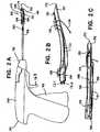
- FIG. 2Aschematically illustrates a side view of an exemplary embodiment of the tissue repair assembly 100, disposed on a delivery device 150 of the present invention, the delivery device 150 having a distal end 152 and a proximal end 154.
- the delivery device 150is seen to comprise a substantially tubular distal delivery member 156 extending distally from a proximal handle 158.
- FIGs. 2B and 2Cillustrate more detailed views of a distal portion of the delivery member 156 with the tissue repair assembly 100 disposed thereon, in respective side and top views.
- the first 106 and the second fixation member 108, with at least a portion of the suture 110 extending therebetween,are seen to be slidably retained along and at least partially within the delivery member 156.
- the delivery device 150is also seen to comprise at least one deployment rod 160 distally slidable in the delivery member 156 for sequentially expelling the first 106 and the second fixation member 108 distally from the delivery member 156.
- the handle 158is seen to comprise at least one manually actuable trigger 162, actuable for distally sliding one of the at least one deployment rod 160.
- the delivery member 156comprises a curve 164 along its length. In another embodiment (not shown), the delivery member 156 is substantially straight between the handle 158 and the distal end 152.
- each of the first 106 and the second fixation members 108is slidably retained in a longitudinal slot 166 in the delivery member 156, the slot 166 extending proximally from the distal end 152 toward the handle 158, and having opposing longitudinal edges 168 for slidably retaining the first 106 and the second fixation member 108.
- the deployment rod 160initially rides underneath the second fixation member 108 outside of the lumen at the distal end of the delivery member 156 through which the rod 160 slides.
- a second trigger 163is engaged which causes a second deployment rod 161 to move distally and push the second fixation member 108 along the slot into a firing position (the position initially occupied by the first fixation member 106) within the lumen and ready to be deployed by the rod 160 when the trigger 162 is engaged.
- the delivery member 156terminates distally in a tissue-penetrating tip 170.
- the delivery member 156terminates distally in a blunt tip.
- each of the first 106 and the second fixation member 108is retained on the delivery member 156 in an orientation that presents a minimum cross section of the respective fixation member for insertion into or through tissue along with the delivery member 156.
- a resilient tube 172is shown in FIG. 2A positioned about the delivery member 156.
- the resilient tube 172is fabricated from a resilient, transparent silicone material.
- the tube 172is omitted from FIGs. 2B and C for clarity.
- the resilient tubeis seen to be positioned about the delivery member 156 along a portion of the delivery member encompassing the locations along the delivery member 156 of the first 106 and the second 108 fixation member and at least a portion of the suture therebetween. Friction between the resilient tube 172 and the fixation members 106, 108 and suture retained therein, retains the first 106 and the second fixation members 108 at predetermined longitudinal positions along the delivery member 156 before delivery of the respective fixation members to tissue.
- the resilient tube 172similarly provides suture management for the tissue repair assembly 100 by maintaining the suture along the delivery member.
- a distal end 174 ofthe resilient tube 172provides a soft depth stop for insertion of the delivery member 156 into tissue before deploying either or both of the first 106 and the second fixation member 108
- FIGs. 3A-3Fillustrate an exemplary method for repairing a tissue defect.
- the delivery member 156, the tissue repair assembly 100 retained thereonis seen to have been passed through a damaged body tissue 180 having a first tissue surface 182 and a second tissue surface 184, to a first location 186 at the second tissue surface 184, where the first fixation member 106 is seen to have been slidingly expelled from the distal end of the delivery member 156, positioning the first fixation member 106 proximate to the first location 186.
- the damaged body tissue 180is seen to comprise a tissue defect 188.
- the first location 186is selected by the surgeon so that the completed repair will apply compression to the defect 188.
- the tissue defect 188is a meniscal tear and the compression is effective to close the tear.
- various suture limbs extending from individual fixation membersare shown laterally separated from one another through the tissue 180 between the first 182 and the second tissue surface 184, but that in an actual tissue repair, the various suture limbs, follow a substantially common path adjacent to one another through the tissue 102.
- the first fixation member 106can be expelled from the delivery member 156 within the material of the damaged body tissue 180, or within or adjacent to a surface of another body tissue.
- the surgeonmay elect to pass the deployment member 156 to the first location 186 directly through the tissue defect 188, adjacent to the tissue defect 188, or through another area of tissue where the deployed tissue repair assembly 100 will be effective to apply compression across the tissue defect 188.
- the delivery member 156is seen to have been retracted from the damaged body tissue 180, leaving the first fixation member 106 proximate to the first location 186.
- the first fixation member 106while slidably retained on the delivery member 156, presents a minimum cross section for penetrating tissue.
- the first fixation member 106will toggle so that the respective tissue contact surface 112 lodges against the second tissue surface 184 at the first location 186, presenting a maximum cross section of the first fixation device 106 to resist pullout through the damaged tissue 180.
- the delivery member 156, the second fixation member 108 still retained thereon,is seen to have been passed a second time through the damaged body tissue 180, to a second location 190 at the second tissue surface 184, where the second fixation member 108 is seen to have been slidingly expelled from the distal end of the delivery member 156, positioning the second fixation member proximate to the second location 190.
- the criteria by which the surgeon selects the second location 190 and the path of the delivery member 156 through tissueare parallel to the criteria used to select the first location 186 and the associated path through tissue.
- each of the first 186 and the second location 190is selected by the surgeon so that the completed repair will apply compression to the tissue defect 188.
- the second fixation member 108can be expelled from the delivery member 156 within the material of the damaged body tissue 188, or within or adjacent to a surface of another body tissue.
- the delivery member 156is seen to have been retracted from the damaged body tissue 188, leaving the second fixation member 108 proximate to the second location, and leaving a portion of the suture loop 132 comprising the first suture limb 134 and the second limb 136 positioned adjacent a spanned section 192 of the first tissue surface 182.
- the second fixation member 108while slidably retained on the delivery member 156, presents a minimum cross section for penetrating tissue.
- the second fixation member 108Upon expulsion from the delivery member 156, and in response to tension applied to one or both of the first limb 134 the second limb 136, the second fixation member 108 toggles so that the respective tissue contact surface 122 lodges against the second tissue surface 184 at the second location 190, presenting a maximum cross section of the second fixation device 108 to resist pullout through the damaged tissue 180.
- the tensioning limb 138is seen to have been tensioned with respect to the first fixation member 106, shortening the suture loop 132 and applying a compressive force to the tissue defect 188.
- the tissue defect 188is a meniscal tear and the compressive force is effective to close the tear.
- the portion of the suture loop 132 adjacent the spanned section 192 of the first tissue surface 182remains substantially on the first tissue surface 182 after the tensioning.
- the tensioningcauses the suture comprising the loop 132 to locally compress the first tissue surface 182, so that no suture is exposed above the remainder of the first tissue surface 182 with sufficient tensioning the suture comprising the loop 132 embeds into the damaged tissue 180 below the first tissue surface 182, so that no suture is exposed above the remainder of the first tissue surface 182.
- the tensioning limb 138is seen to have been trimmed at or below the first tissue surface 182, leaving none of the tensioning limb 138 proud of the first tissue surface 182.
- the damaged tissue 180is a meniscus of a knee
- the tissue defectis a meniscal tear
- the first tissue surface 182is the articulating surface of the meniscus
- the second tissue surface 184is the peripheral rim of the meniscus
- each ofthe first 106 and the second fixation member 108is deployed in the peripheral meniscal capsule.
- two or more tissue repair assemblies of the present inventionare used to repair a tissue defect, or to repair physically adjacent defects in a tissue.
- first and second locations for the respective first 106 and second fixation member 108is dependent on many factors including, but not limited to the type of tissue comprising the defect, the nature and extent of the defect, its location in the tissue, and its proximity to other tissues and other defects that may be present near the surgical site.
- the first and second locations for respective first and second fixation memberscan be on a single continuous surface of a damaged tissue.
- the first and the second locationare on opposite sides of a tissue defect along a tissue surface.
- the first and the second locationcan be on opposing tissue surfaces, the tissue defect therebetween.
- the first location and the second locationcould be on different tissues.
- FIGs. 4A-4Cschematically illustrate respective top, end and side views of an exemplary embodiment of a three-opening fixation member 200 of the present invention.
- the three-opening fixation member 200is the first fixation member 106 of the tissue repair assembly 100 disclosed hereinabove.
- the three-opening fixation member 200is seen to comprise a first body 202 having a respective first surface 204, a respective second surface 206, and three through openings comprising a first 208, a second 210, and a third opening 212 through the body 202 between the respective first surface 204 and second surface 206.
- the three-opening fixation member 200is the first fixation member 106, the respective first surface 204 is the tissue contact surface 112 and the respective second surface 206 is the back surface 114.
- the three-opening fixation member 200is symmetrical about a plane 214 between the respective first 204 and second surface 206.
- the respective first 204 and second surface 206can be asymmetrical about the plane 214.
- Each of the three through openings 208, 210, 212, and one or both of the respective first 204 and second surface 206 adjacent to and therebetweenis smoothly rounded to optimize slidability of suture through and between the openings.
- One or more of the three through openings 208, 210, 212is elongated in a direction perpendicular to a line interconnecting the one or more opening with an adjacent one of the three through openings. Elongation of the one or more opening enhances the slidability of suture through the respective opening.
- the first body 202is also seen to comprise a longitudinal groove 216 on each of the respective first 204 and second surface 206. Each groove 216 is adapted to slidingly engage with one of the edges 168 of the longitudinal slot 166 in the delivery member 156, to retain the three-opening fixation member 200 in the delivery member 156.
- FIGs. 5A-5Cschematically illustrate respective top, end and side views of a further embodiment of a two-opening fixation member 220 of the present invention.
- the two-opening fixation member 220is the second fixation member 108 of the tissue repair assembly 100 disclosed hereinabove.
- the two-opening fixation member 220is seen to comprise a second body 222 having a respective first surface 224, a respective second surface 226, and two through openings comprising a respective first 228 and second opening 230 through the second body 222 between the respective first surface 224 and second surface 226.
- the two-opening fixation member 220is the second fixation member 108, the respective first surface 224 is the tissue contact surface 122 and the respective second surface 226 is the respective back surface 124.
- the two-opening fixation member 220is symmetrical about a respective plane 232 between the respective first 224 and second surface 226.
- the respective first 224 and second surface 226are asymmetrical about the respective plane 232.
- the first 228 and the second through opening 230 in the two-opening fixation member and one or both of the respective first 224 and second surface 226 adjacent to and therebetweenare smoothly rounded to optimize slidability of suture through and between the openings.
- One or both of the two through openings 228, 230can be elongated in a direction perpendicular to a line interconnecting the two through openings 228, 230 to enhance slidability of suture through the respective openings.
- the second body 222is also seen to comprise a respective longitudinal groove 234 on each of the respective first 224 and second surface 226. Each respective groove 234 is adapted to slidingly engage with one of the edges 168 of the longitudinal slot 166 in the delivery member 156, to retain the two-opening fixation member 220 in the delivery member 156.
- the three-opening fixation member 200 and the two-opening fixation member 220can be fabricated from any biocompatible material, and can be of the same, or of a different composition from one another.
- at least one of the fixation members 200, 220is nonabsorbable.
- at least one of the fixation members 200,220is fabricated from polyetheretherketone (PEEK) polymer.
- PEEKpolyetheretherketone
- at least one of the fixation members 200, 220is bioabsorbable.
- FIG. 6schematically illustrates a perspective view of an exemplary embodiment of a tissue repair assembly 250 of the present invention comprising the three-opening fixation member 200 and the two-opening fixation member 220. It has the same construction as the tissue repair assembly 100 disclosed hereinabove, wherein the suture 110 comprises the locking, sliding knot 130, the first 134 the second 136 and the tensioning limb 138, the first 134 and the second limb 136 comprising the suture loop 132.
- An engagement portion of the suture 110is positioned slidingly through the locking, sliding knot 130 at a location, hereinafter, a "post" 252 along the suture 110, substantially adjacent to the respective second surface 206 of the first fixation member 200, between the first 208 and the third opening 212, the post 252 comprising a slidable transition between the first limb 134 and the tensioning limb 136 along the suture 110.
- the locking, sliding knot 130Upon tensioning the tensioning limb 138 with respect to the three-opening fixation member 200 to shorten the loop 132, the locking, sliding knot 130 locks the post 252 therein, substantially preventing the loop 132 from lengthening again. Locking, sliding knots are well known in the surgical art.
- the locking, sliding knotis a bunt line sliding knot, a type of locking, sliding knot known in the surgical arts, as well as in other arts such as nautical arts.
- itfurther comprises a stopper knot 254 to stabilize a suture tail 256 extending from the locking, sliding knot 130.
- the stopper knot 254can comprise a single figure eight knot.
- the three-opening fixation member 200 and the two-opening fixation member 220are preferably each fabricated from PEEK, and the suture 110 is a partially bioabsorbable, high strength suture comprising ultra high molecular weight polyethylene (UHMWPE) and polydioxanone (PDS). More preferably, the UHMWPE and PDS suture is an OrthocordTM suture, distributed by Depuy Mitek, of Raynham, Massachusetts.
- UHMWPEultra high molecular weight polyethylene
- PDSpolydioxanone
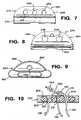
- FIG. 7 through FIG. 9schematically illustrate top views of various alternative embodiments of fixation members that can comprise tissue repair assemblies of the present invention.
- FIG. 7illustrates a top view another embodiment of a three-opening fixation member 260 that resembles the fixation member 200 of FIGs 4A-4C and FIG. 6 , except that in the three-opening fixation member 260 illustrated in FIG. 7 , each of three openings 262, 264, 266 through a respective body 268 between a respective first 270 and second surface 272, are circular in cross section.
- FIG. 8illustrates a top view another embodiment of a two-opening fixation member 274 that resembles the fixation member 220 of FIGs 5A-5C and FIG. 6 , except that in the two-opening fixation member 274 illustrated in FIG. 8 , each of two openings 276, 278 through a respective body 280 between a respective first 282 and second surface 284 are circular in cross section.
- FIG. 9schematically illustrates an embodiment of a single-opening fixation member 286 of the present invention.
- the single-opening fixation member 286is seen to resemble the two-opening fixation member 274 and the three-opening fixation member 260, but having only a single opening 288 through a respective body 290 between a respective first 292 and second surface 294.
- the tissue repair assembly 250comprising the three-opening fixation member 200 and the two-opening fixation member 220
- the two-opening fixation member 220is replaced with the single-opening fixation member 286, and a suture loop extending between the three-opening fixation member 200 and the single opening fixation member 286, is positioned through the single opening 288.
- a suture loop extending from a substantially three-opening fixation membercomprises two or more fixation members therealong, through each of which the suture loop is positioned.
- sutureis passed substantially in one longitudinal direction only through a locking, sliding element (a restriction element) associated with a fixation member from which three limbs of suture extend.
- the restriction elementcan be any type of restriction element through which suture can pass in a preferred longitudinal direction, and is restricted from passing in an opposite longitudinal direction.
- the restriction elementis a locking, sliding suture knot.
- the restriction elementcomprises one or more opening in the fixation member adapted to pass a barbed suture having a preferred direction of sliding through the one or more opening.
- the restriction elementis a unidirectional passage through or around the fixation member itself.
- F1G. 10schematically illustrates a cross sectional side view of a portion of the tissue repair assembly 250 of FIG. 6 , showing a cross-sectional view of the three-opening fixation member 200, and the portion of the suture 110 positioned therethrough, with the locking, sliding knot 130 lodged against the second surface 206.
- the internal surfaces of the three openings 208, 210, 212 through the three-opening fixation member 200 and the portions of the respective first 204 and second surface 206 therebetweenare seen to be rounded to optimize sliding of the suture 110 therethrough and therealong, respectively.
- Tissue repair assemblies of the present inventioncan be constructed in a variety of configurations, comprising fixation members of any size and proportions suited to repairing a particular tissue defect, selection of the size and type of suture used, and variations in the routing of suture with respect to the fixation members.
- the number of through openings required in fixation members used to construct a tissue repair assembly of the present inventionis in turn selected based on the routing of the suture.
- FIGs. 11A-11Fschematically illustrate various alternative embodiments of tissue repair assemblies of the present invention, differing in configuration from the embodiments illustrated hereinabove with regard to one or both of suture routing between two fixation members, and the number of openings provided through the respective fixation members. It is to be noted that the total number of openings provided through any of the fixation members disclosed herein can exceed the number of openings required for a particular suture routing without deviating from the intent or scope of the present invention.
- FIG. 11Aillustrates a first alternative embodiment tissue repair assembly 300 comprising a first fixation member 302 and a second fixation member 304.
- the tissue repair assembly 300 of FIG. 11Ais also seen to comprise a length of suture 306 and a restriction element 308.
- the restriction element 308is a locking, sliding knot formed from the suture 306.
- the length of suture 306further comprises a first limb 310 continuous with a second limb 312, the first 310 and the second limb 312 together comprising a suture loop 314 connecting the first 302 to the second fixation member 304.
- the second limb 312is substantially fixedly connected to the restriction member 308.
- the second limb 312extends through the restriction member 308 and is continuous with a suture tail 316 that is terminated by a stopper knot 318 as disclosed hereinabove.
- the first limb 310is routed slidingly through the restriction member 308 and is continuous with a tensioning limb 320.
- sutureis routed through one or more opening through various fixation members. The suture is generally slidingly routed through the one or more opening to ensure smooth operation of the assembly, for deploying the respective fixation members in tissue, and for sliding suture through the assembly to approximate a tissue defect.
- the various alternative embodiments illustrated in each of FIG. 11A through FIG. 11Fcomprise the length of suture 306 and components thereof, but vary in their routing about and between respective first and second fixation members.
- the first fixation member 302is seen to comprise a first 322, a second 324 and a third opening 326 therethrough.
- the second fixation member 304is seen to comprise two openings 328, 330 therethrough.
- the suture loop 314is seen to be routed through each of the two openings 328, 330 in the second fixation member 304.
- the first limb 310is seen to be routed through the first opening 322 in the first fixation member 302 and to the restriction element 308.
- the second limb 312is seen to be routed through the third opening 326 in the first fixation member 302, and to the restriction element 308.
- the tensioning limb 320is seen to be routed from the restriction element 308 and through the second opening 324 in the first fixation member 302.
- Tension applied to the tensioning limb 320 with respect to the first fixation member 302is effective to draw suture through the restriction member 308, thereby decreasing the size of the loop 314.
- the tissue repair assembly 300is seen to resemble the tissue repair assemblies 100, 250 disclosed hereinabove, except that in the embodiment of FIG. 11A , the tensioning limb 320 is routed through a central opening in the respective fixation member 302, as opposed to being routed through a differently positioned in the earlier disclosed tissue repair assemblies 100, 250.
- FIG. 11Billustrates a second alternative embodiment of a tissue repair assembly 332 comprising the first 302 and the second fixation member 304 of the embodiment of FIG. 11A , but differing in the suture routing about and through the first fixation member 302, and in construction of the restriction element 308.
- the restriction element 308is a locking, sliding suture knot affixed to the first fixation element 302 by the suture tail 316 being routed through the third opening 326 in the first fixation device 302 and secured therethrough by the stopper knot 318.
- Each of the first 310 and the second limbs of suture 312are seen to be routed through one of the first 322 and the second openings 324 in the first fixation member 302. Further, in the embodiment of FIG. 11B , the tensioning limb 320 is seen to be routed around the first fixation member 302, as opposed to being routed through an opening in the first fixation member 302, as illustrated for the first alternative embodiment of the tissue repair assembly 300 illustrated in FIG. 11A .
- FIG. 11Cillustrates a third alternative embodiment of a tissue repair assembly 334.
- the tissue repair assembly 334 of FIG. 11Cis seen to comprise a first fixation member 336 having a first 338 and a second opening 340 therethrough.
- the tissue repair assembly 334is also seen to comprise a second fixation member 342 having a single opening 344 therethrough.
- the suture loop 314is seen to be routed through the single opening 344 in the second fixation member 342, and each ofthe first 310 and the second limb 312 of suture is seen to be routed through one of the first 338 and the second opening 340 in the first fixation member 336.
- the tensioning limb 320is seen to be routed around the first fixation member 336.
- FIG. 11DA fourth alternative embodiment of a tissue repair assembly 346 is illustrated in FIG. 11D .
- the tissue repair assembly 346 illustrated in FIG. 11Dresembles the tissue repair assembly 334 illustrated in FIG. 11C , except that in the embodiment illustrated in FIG. 11D , the tensioning limb 320 is routed from the restriction element 314, through the second opening 340 in the first fixation member 336.
- one of the first 310 and the second limb of suture 312is seen to be routed through the first opening 338 in the first fixation member 336, and the other of the first 310 and the second limb of suture 312 is seen to be routed around the first fixation member 336.
- FIG. 11Eillustrates a fifth alternative embodiment of a tissue repair assembly 348 comprising a first 350 and a second fixation member 352 each having a single respective opening 354, 356 therethrough.
- the suture loop 320is seen to be routed through the single opening 356 in the second fixation member 352.
- One of the first 310 and the second limb of suture 312is seen to be routed through the single opening 354 in the first fixation member 350, and the other of the first 310 and the second limb of suture 312 is seen to be routed around the first fixation member 350.
- the tensioning limb 320is seen to be routed around the first fixation member 350.
- FIG. 11Fillustrates a sixth alternative embodiment of a tissue repair assembly 358 comprising a first 360 and a second fixation member 362, each having two respective openings 364, 366, 368, 370 therethrough.
- the suture loop 314is seen to be routed through each of the two openings 368, 370 in the second fixation member 362 and each of the first 310 and the second suture limb 312 is routed directly to the restriction member 308, which is positioned adjacent to the first fixation member 360, between the first 360 and the second fixation member 362.
- the restriction element 308is a locking, sliding suture knot affixed to the first fixation member 360 by the suture tail 316 being routed through one 366 of the two respective openings 364, 366 in the first fixation device 360 and secured therethrough by the stopper knot 318.
- the tensioning limb 320is seen to be routed through the other 364 of the two respected openings 364, 366 in the first fixation device 360.
- any of the embodiments of respective second fixation memberscan be combined with any of the embodiments of respective first fixation members, associated restriction elements and suture routing to provide additional embodiments within the intent and scope if the present invention defined by the claims.
- Tissue repair assemblies of the present inventionhave several advantages.
- a meniscal repair procedure using a tissue repair assembly of the present inventioncan provide a finished tissue repair where only suture, no hard bodies or knots, are left on the articulating (that surface facing the femur) surface of the meniscus in the knee, thus supporting healing and minimizing the probability that articulating cartilage contacting the meniscus will be damaged when the patient flexes the knee joint after the surgery.
- the repairscan be performed in any orientation with respect to a damaged tissue and the associated tissue defect.
- Tissue repair assemblies of the present inventionprovide additional flexibility for the surgeon because the tissue repair assemblies include no fixed lengths of suture to limit the relative locations of the two tissue fixation members.
- tissue repair assemblies of the present inventiondo not restrict the minimum distance between the two fixation members.
- tissue repair assemblies of the present inventionan entire meniscal repair can be performed from the articulating side of the meniscus, an approach that minimizes surgical trauma to surrounding tissue.
- Another advantageis that the strength and stability of a repair performed using tissue repair assemblies of the present invention is provided by two uninterrupted, continuous limbs of suture, the limbs including no joints, knots, or retainers therealong between first and second anchoring members. Further advantageously, providing two sutures that completely span the anchoring locations provides superior distribution of forces on the repaired tissue, relative to single, knotted or joined suture segments spanning the anchoring locations.
- Tissue repair assemblies of the present inventionare also very versatile in their application, including applicability to meniscal repairs, approximation of partial shoulder rotator cuff tears, and any other soft tissue repair where two tissues, or damage within a tissue, requires surgical approximation.
- the tissue repair assembliescould be used to anchor soft tissue to bone
Landscapes
- Health & Medical Sciences (AREA)
- Surgery (AREA)
- Life Sciences & Earth Sciences (AREA)
- Medical Informatics (AREA)
- Nuclear Medicine, Radiotherapy & Molecular Imaging (AREA)
- Engineering & Computer Science (AREA)
- Biomedical Technology (AREA)
- Heart & Thoracic Surgery (AREA)
- Molecular Biology (AREA)
- Animal Behavior & Ethology (AREA)
- General Health & Medical Sciences (AREA)
- Public Health (AREA)
- Veterinary Medicine (AREA)
- Rheumatology (AREA)
- Surgical Instruments (AREA)
- Prostheses (AREA)
Description
- The invention relates generally to devices for repairing tissue. More specifically, the invention relates to suture anchoring devices arthroscopic repair of tissue defects.
- A variety of injuries and conditions require repair of soft tissue damage, or reattachment of soft tissue to bone and/or surrounding tissue. For example, when otherwise healthy tissue has been torn away from a bone, such as a shoulder rotator cuff tendon being partially or completely torn from a humerus (a rotator cuff tear), surgery is often required to reattach the tissue to the bone, to allow healing and a natural reattachment to occur. A number of devices and methods have been developed for performing these surgical repairs, some of the more successful methods including the use of suture anchors or, generically, "suture fixation members," which typically include an anchor body having one or more suture attachment feature, and a tissue or bone engaging feature for retaining the suture anchor within or adjacent to the tissue or bone. Depending on the specific injury, one or more suture anchor connected to, or interconnected by, one or more segment of suture, may used to perform the repair.
- Surgery can also be required when a tear occurs in the substance of a single type of tissue, for example in the meniscus of the knee (a meniscal tear). One method of repairing such a tear is to stitch it closed by passing a length of suture through the tissue and tying the suture. Suture can also be used in conjunction with one or more suture anchor to repair such tissue tears. Sutures can be fastened to suture anchors and to tissue using knots tied by the surgeon during a repair procedure, or using "knotless" devices and methods, where one or more anchor and one or more suture can be connected and tensioned without the surgeon needing to tie knots during the surgery. Knotless anchoring is of particular utility for minimally invasive surgeries such as endoscopic or arthroscopic repairs, where the surgeon must remotely manipulate the suture at the surgical site using tools inserted through a small diameter cannula or endoscopic tube, which can make the knotting process difficult and tedious.
- Various methods are used to provide knotless anchoring, including anchors that automatically lock a suture in position as the anchor is deployed in tissue, anchor components that can controllably lock a suture to the anchor after the anchor is deployed, devices that enable a suture to slide through them in one direction only, and preformed knots that can be tightened by the surgeon using a simple tool, or by tensioning one or more suture strand extending from the knot.
- While many suture anchoring systems have been developed for repairing torn tissue, current devices are not without their drawbacks. Some knots or other anchor components may "stand proud" above the repaired tissue's surface especially that surface facing weight bearing contact with bone such as the interface between the femur and the meniscus and interfere with movement and healing of, for example, articulating joint tissue, or the knot's position relative to the anchor or nearby tissue may not be fully under the surgeon's control, in some situations providing a less than optimal repair. In surgeries where two or more suture anchors are joined by suture to repair an injury, any knots or joined suture segments positioned along the suture connecting the anchors to one another can become stress points that limit the ultimate strength of the surgical repair or contribute to surgical trauma.
US 2005/0251208 describes a locking anchor assembly having distal anchor and proximal anchor with a suture extending between the two anchors. A terminal end of the suture may be knotted or otherwise retained by the proximal anchor and routed through a top opening in the proximal anchor and back through a middle opening in the proximal anchor to create looped portion. The suture may be routed from the middle opening and through, and back through, the distal anchor via two openings. The suture may then be routed back to the proximal anchor through a bottom opening and wrapped about the looped portion to continue on proximally. This knotted configuration facilitates advancement of the proximal anchor towards distal anchor but chokes the suture when the proximal anchor is moved in an opposing direction. - Accordingly, there remains a need for improved methods and devices for repairing torn or damaged tissue, and in particular for methods and devices suitable for arthroscopic repair of torn or otherwise damaged tissue using suture anchors. There also remains a need for methods and devices that reduce the risk of damage to the tissue being repaired, and that provide a low profile to eliminate interference with movement and healing in articulating joints.
- Accordingly, the present invention provides embodiments of suture anchoring devices for repairing damaged tissue. The apparatus according to the present invention is defined in claim 1. Further embodinments are defined in the dependent claims. An apparatus according to the present invention comprises first and second fixation members, with each of the first and the second fixation members having a first surface, an opposing second surface, first and second through openings defined between the first surface and the second surface. A flexible element couples the first and the second fixation members, the flexible element having a first end, a second end and a length therebetween which extends from the first end, in order, along a first end section of suture, through the first opening in the first fixation member from the respective first surface to the respective second surface, through the first opening in the second fixation member from the respective second surface to the respective first surface, through the second opening in the second fixation member from the respective first surface to the respective second surface, through the second opening in the first fixation member from the respective second surface to the respective first surface, and along a second end section of suture. The first fixation member has a third through opening defined between the respective first and second surface. A sliding, locking knot is formed between the first end section and the second end section, with the first end section positioned slidably through the knot and extending from the knot and through the third opening from the first surface to the second surface.
- In one aspect of the invention, the first, second and third openings through the first fixation member are arranged in substantially a straight line along the respective first and second surface. Preferably, the first and the second fixation members comprise rounded surfaces between adjacent openings on each respective surface, for sliding the flexible element therealong. In one aspect of the invention each of the openings has a substantially circular cross section. Alternatively, one or more of the openings has an elongated cross section. Preferably, tension applied to the second end section with respect to the first fixation member is effective to decrease a distance between the first and the second fixation member along the flexible member coupling the first and the second fixation member.
- In one aspect of the invention, the first and the second fixation members further comprises a substantially linear groove in each of the respective first and second surfaces, the groove extending from a first end of the respective surface to an opposite end of the respective surface, the groove in the second surface being substantially parallel to the groove in the first surface. A delivery device has an elongated delivery member within which at least a portion of each of the first and the second fixation members, coupled by the flexible element, is longitudinally and slidably received, preferably with their grooves slidably engaged with a slot in the delivery member.
- Preferably, the flexible element comprises a suture. In one aspect of the invention the flexible element comprises polyethylene. In another aspect of the invention the flexible element comprises polyethylene and a bioabsorbable polymer, preferably the bioabsorbable polymer comprises polydioxanone.
- Preferably, the sliding, locking knot is a bunt line knot.
- Preferably, a delivery device is provided which comprises a cannula having a proximal end and a distal end, and a longitudinal slot in a wall of the cannula which extends from the distal end toward the proximal end, the cannula is defined by opposing longitudinal edges along the slot. The first and the second fixation device are received in the cannula along the slot, with the slot edges slidingly engaged in respective grooves in each of the first and the second fixation device. Preferably, a deployment rod is positioned in the cannula, a handle mechanically couples to the proximal end of the cannula, and a manually actuable member is associated with the handle to translate the deployment rod distally in the cannula for expelling one of the first and the second fixation device slidingly from the distal end of the cannula.
- An apparatus according to the present invention comprises first and second fixation members. Each of the first and the second fixation members haying a first surface and an opposing second surface, first, second and third through openings defined between the first surface and the second surface of the first fixation device, and one or more through openings defined between the first surface and the second surface of the second fixation device. A flexible element couples the first and the second fixation members. It has a first end, a second end and a length therebetween, the length extending from the first end, in order, along a first end section of suture, through the first opening in the first fixation member from the respective first surface to the respective second surface, through at least one of the one or more opening in the second fixation member from the respective second surface to the respective first surface, through the second opening in the first fixation member from the respective second surface to the respective first surface, and along a second end section of suture. A sliding, locking knot is formed between the first end section and the second end section, the second end section extending from the knot and through the third opening from the first surface to the second surface.
- An apparatus according to the present invention comprises first and second fixation members coupled by two continuous sections of suture extending therebetween. The first fixation member has a first surface and an opposing second surface. The two suture sections are continuous with one another and slidable through an opening through the second fixation member. Each of the two sections of suture extend through respective first and second through openings in the first fixation member from the second surface to the first surface. A sliding, locking knot joins the two continuous sections of suture adjacent to the first surface. A third through opening extends between the first surface and the second surface and one of the two continuous sections of suture extends from the knot and through the third opening from the first surface to the second surface.
- An apparatus according to the present invention provides for repairing a defect in a body tissue. It comprises a first fixation member having a first surface and an opposing second surface, and first, second and third through openings between the first and the second surface. A second fixation member has one or more through openings. The first and the second fixation members are coupled by a continuous length of suture defining a loop joined by a sliding, locking knot positioned substantially adjacent to the first side of the first fixation member. The loop extends from the knot slidably through, in order, the first opening in the first fixation member, at least one of the one or more openings in the second fixation member, the second opening of the first fixation member, and returns to the knot. An end section of the continuous length of suture extends from the knot and through the third opening of the first fixation member from the first side to the second side. Tensioning the end section with respect to the first fixation member is effective to shorten the loop.
- Preferably, the knot is a bunt line knot, and also preferably the second surface is adapted to contact the tissue being repaired, and the knot is maintained adjacent to the first surface.
- A method in which the present invention can be used provides for repairing a defect in a body tissue. The method comprises the steps of: passing a first fixation member along a first delivery path through the tissue to a first location on a first surface area of the tissue, the first fixation member having opposing first and second surfaces, a sliding and locking suture knot adjacent to the first surface, the suture knot comprising suture, three limbs of suture extending from the second surface along the delivery path, the three limbs of suture each continuous with the suture comprising the knot, a first two of the three limbs together comprising a continuous loop of suture slidingly connected to a second fixation member, the loop having a loop length; tensioning at least one of the three sections of suture to deploy the second surface against the tissue at the first location; passing the second fixation member along a second delivery path through the tissue to a second location on a second surface area of the tissue; and
tensioning the third limb of suture to reduce the loop length between the first fixation member and the second fixation member. - Preferably, tensioning the third limb of suture deploys the second fixation member against the tissue at the second location and also applies a compressive force to reduce the tissue defect.
- Preferably, the first fixation member comprises a first, a second, and a third through opening between the first side and the second side, each of the first, second and third limb positioned through the respective opening and the second fixation member comprises two through openings, and the loop passes slidingly through both openings.
- In one aspect of the invention, the first location and the second location are on a single surface of the tissue. In another aspect of the invention the first location and the second location are on opposing surfaces of the tissue.
- An apparatus according to the claimed invention comprises a first fixation member having opposing first and second surfaces. A sliding and locking suture knot sits adjacent to the first surface. It comprises suture, three limbs of which extend from the second surface, are continuous with the suture comprising the knot, each ofwhich are positioned through a respective through opening between the first surface and the second surface. A first two of the three limbs together comprise a continuous loop of suture slidingly connected to a second fixation member. The loop has a loop length. The knot is configured so that tension applied to the third limb with respect to the first fixation member is effective to reduce the loop length
- An apparatus according to the present invention comprises a first fixation member having opposing first and second surfaces, with first, second and third through openings extending between the first and the second surfaces, and respective first, second and third limbs of suture positioned through the respective first, second and third openings. The first and the third limbs are positioned slidably through the respective first and third opening and the first and the second limbs are continuous with one another to form a suture loop extending from the second surface. A second fixation member has one or more opening therethrough with the loop positioned slidably through at least one of the one or more openings through the second fixation member. A restriction element is associated with the first fixation member and is adapted to slidably pass suture therethrough in a first direction, but not in a second, opposite direction. The first and the third limbs are continuous with one passing through the restriction member adjacent the first surface. Tension applied to the third limb with respect to the first fixation member is effective to reduce the loop length by sliding the third and the first limb through the respective third and first opening.
- An apparatus according to the claimed invention comprises a first fixation member and a second fixation member, with at least one opening through the second fixation member. Two limbs of suture form a continuous loop of suture extending from the first fixation member with a portion of the loop positioned slidably through the at least one opening through the second fixation member. The first fixation member comprises a restriction element through which an extension of one of the two limbs is positioned to pass slidingly in a first longitudinal direction, but is restricted from sliding in a second, opposite longitudinal direction. The two limbs and the extension extending from a common surface of the first fixation member.
- An apparatus according to the present invention provides for repairing a body tissue having a surface. The apparatus comprises first and second fixation members, each of the first and the second fixation members having a respective contact surface adapted to be positioned in contact with the tissue surface. A continuous loop of suture extends between respective contact surfaces of the first and the second fixation member, the loop having a length, and being slidably positioned through one or more opening through the second fixation member. A tensioning limb of suture extends from the contact surface of the first fixation member so that tension applied to the tensioning limb with respect to the first fixation member is effective to reduce the length of the loop.
- Preferably, the tensioning limb is continuous with the suture comprising the loop. In one aspect of the invention the first fixation member comprises a locking, sliding knot through which the tensioning limb is positioned. Preferably, the sliding knot is position adjacent a non-contact surface on the first fixation member, the non-contact surface being opposed and opposite to the contact surface. Preferably, the tensioning limb can pass slidingly through the knot in a first longitudinal direction along the suture, and is restricted from sliding through the knot in an opposite longitudinal direction.
- This invention is described with particularity in the appended claims. The above and further aspects of this invention may be better understood by referring to the following description in conjunction with the accompanying drawings, in which like numerals indicate like structural elements and features in various figures. The drawings are not necessarily to scale, emphasis instead being placed upon illustrating the principles of the invention.
FIG. 1 is a cross sectional view of an exemplary embodiment of a tissue repair assembly of the present invention, implanted in a body tissue;FIG. 2A is a side elevation view of an exemplary embodiment of a tissue repair assembly ofthe present invention, disposed on a delivery device of the present invention;FIGs. 2B and 2C are side elevation and top views, respectively, of a distal portion of the delivery tool illustrated inFIG. 2A ;FIGs. 3A-3F are cross-sectional views of an exemplary method for repairing a tissue defectFIGs. 4A-4C are respective top plan, end elevation and side elevation views of an exemplary embodiment of an fixation member of the present invention having three through openings for receiving suture;FIGs. 5A-5C are top plan, end elevation and side elevation views of another embodiment of an fixation member of the present invention having two through openings for receiving suture;Fig. 6 is a perspective view of a tissue repair assembly of the present invention employing the fixation members ofFIGs. 4A-4C and FIGs. 5A-5C ;FIG. 7 is a side elevation view of an alternative embodiment of an fixation member ofthe present invention having three through openings for receiving suture;FIG. 8 is a side elevation view of an alternative embodiment of an fixation member of the present invention having two through openings for receiving suture;FIG. 9 is a side elevation view of a further embodiment of an fixation member of the present invention having one through opening for receiving suture;FIG. 10 is a cut-away view taken along lines 10 - - 10 ofFIG. 6 ;FIGs. 11A-11F are top cut-away views of further embodiments of tissue repair assemblies of the present invention.- Devices of the present invention enable a surgeon to consistently and reliably repair tissue tears and separations using two fixation members interconnected by continuous segments of suture. Surgeries using the devices of the present invention are performed without the surgeon having to tie any suture knots, and are particularly suitable for performing arthroscopic or endoscopic repairs. Repairs performed using the present invention leave no knots, suture joints or other potential stress points along the suture interconnecting the fixation devices, reproducibly position any knots away from tissue areas that are particularly susceptible to post-surgical damage, for example, articulating tissue surfaces. It is to be understood that particular devices disclosed herein are exemplary and not limiting of the present invention, for example, embodiments illustrated herein for repairing in-substance injuries to soft tissue, such as the meniscus of the knee, can be equally applied for repairing partial or complete tears in another type of soft tissue, or for repairing partial or complete separations of one type of tissue from another, for example, separation of a tendon or ligament from a bone.
- Referring more particularly to the figures, FIG. schematically illustrates a cross sectional view of an exemplary embodiment of a
tissue repair assembly 100 of the present invention implanted in abody tissue 102, for repairing adefect 104 in thetissue 102. In an exemplary embodiment, thetissue 102 is a meniscus in a knee and thedefect 104 is a meniscal tear. In another embodiment, thetissue 102 is another type of body tissue. In yet another embodiment, thedefect 104 is a separation between two different types of body tissue. - The
repair assembly 100 is seen to comprise afirst fixation member 106, asecond fixation member 108 and a continuousflexible element 110 interconnecting and extending through the first 106 and thesecond fixation member 108. Theflexible element 110 can comprise any type of flexible element suitable for implantation and use in making surgical repairs, and is hereinafter referred to as "suture." Thesuture 110 can be any type of suture including suture fabricated using natural materials such as silk, and synthetic materials such as polyethylene terephthalate (PET) or other polyester materials. Thesuture 110 can be bioabsorbable, partially bioabsorbable, or nonabsorbable, and can have a circular cross section or another cross section. In one embodiment, thesuture 110 is partially bioabsorbable, comprising polyethylene as a nonabsorbable component, and polydioxanone as a bioabsorbable component. - The
first fixation member 106 is seen to comprise a first tissue-contact surface 112, afirst back surface 114 and a first 116, a second 118 and a third through opening 120 between the first tissue-contact surface 112 and thefirst back surface 114. Thesecond fixation member 108 is seen to comprise a secondtissue contact surface 122, asecond back surface 124 and a respective first 126 and second through opening 128 between therespective tissue contact 122 andback surface 124. In an embodiment, one or more of the respective through openings is adapted for slidably passing thesuture 110 therethrough. In a further embodiment, the respective tissue contact and back surfaces between adjacent openings through each the first 106 and thesecond anchor 108 are rounded to optimize the slidability of thesuture 110 through and among the respective openings. In one embodiment, the cross section of each of the openings is round. In another embodiment, one or more of the openings is elongated in a direction transverse to a line connecting the one or more opening with an adjacent opening through the respective fixation member. - The
suture 110 is seen to comprise a locking, slidingknot 130 adjacent to theback surface 114 of thefirst fixation member 106. The suture is seen to comprise acontinuous loop section 132 extending from the locking, slidingknot 130, theloop section 132 comprising afirst limb 134 and asecond limb 136. Thefirst limb 134 is seen to extend from the locking, slidingknot 130 toward and through the respectivefirst opening 116 in thefirst fixation member 106 from therespective back surface 114 to the respective tissue-contact surface 112, toward and through the respectivefirst opening 126 in thesecond fixation member 108, from the respective tissue-contact surface 122 to therespective back surface 124. Continuing from theback surface 124 of thesecond fixation member 108, thefirst limb 134 is seen to be continuous with thesecond limb 136 in theloop 132, returning through the respectivesecond opening 128 from theback surface 124 to the tissue-contact surface 122 of thesecond fixation member 108, toward and through the respectivesecond opening 118 in thefirst fixation member 106, to the locking, slidingknot 130, completing theloop 132. In an embodiment, theloop 132 is positioned slidably through each of the respective first and second opening through each of the first 106 and thesecond fixation member 108. - In an embodiment, the
second limb 136 is connected fixedly to the locking, slidingknot 130 and thefirst limb 134 extends slidably through the locking, slidingknot 130, to and continuous with atensioning limb 138 that extends from the locking, slidingknot 130 toward and through the third opening 140 from the respectiveback side 114 to thetissue contact side 112 of thefirst anchor 106. An application of tension to thetensioning limb 138 with respect to thefirst anchor 106 is effective to slidingly draw suture from theloop 132 through the respective first opening in the first fixation member, the locking, slidingknot 130 and thethird opening 120, shortening theloop 132 as the transmitted tension further draws a portion of thesecond limb 136 slidingly through the respective second 128 andfirst opening 126 in thesecond fixation member 108. In an embodiment, shortening theloop 132 applies a compressive force for closing thedefect 104 in thetissue 102. It is to be noted that for illustrative purposes inFIG. 1 , the various suture limbs. 134, 136 and 138 are shown laterally separated from one another through thetissue 102, but that in an actual tissue repair using thetissue repair assembly 100, thevarious suture limbs tissue 102. FIG. 2A schematically illustrates a side view of an exemplary embodiment of thetissue repair assembly 100, disposed on adelivery device 150 of the present invention, thedelivery device 150 having adistal end 152 and aproximal end 154. Thedelivery device 150 is seen to comprise a substantially tubulardistal delivery member 156 extending distally from aproximal handle 158.FIGs. 2B and 2C illustrate more detailed views of a distal portion of thedelivery member 156 with thetissue repair assembly 100 disposed thereon, in respective side and top views.- The first 106 and the
second fixation member 108, with at least a portion of thesuture 110 extending therebetween, are seen to be slidably retained along and at least partially within thedelivery member 156. Thedelivery device 150 is also seen to comprise at least onedeployment rod 160 distally slidable in thedelivery member 156 for sequentially expelling the first 106 and thesecond fixation member 108 distally from thedelivery member 156. Thehandle 158 is seen to comprise at least one manuallyactuable trigger 162, actuable for distally sliding one of the at least onedeployment rod 160. In one embodiment, as illustrated inFIG. 2A , thedelivery member 156 comprises acurve 164 along its length. In another embodiment (not shown), thedelivery member 156 is substantially straight between thehandle 158 and thedistal end 152. - In an embodiment, each of the first 106 and the
second fixation members 108 is slidably retained in alongitudinal slot 166 in thedelivery member 156, theslot 166 extending proximally from thedistal end 152 toward thehandle 158, and having opposinglongitudinal edges 168 for slidably retaining the first 106 and thesecond fixation member 108. As shown, thedeployment rod 160 initially rides underneath thesecond fixation member 108 outside of the lumen at the distal end of thedelivery member 156 through which therod 160 slides. After deployment of thefirst fixation member 106, asecond trigger 163 is engaged which causes asecond deployment rod 161 to move distally and push thesecond fixation member 108 along the slot into a firing position (the position initially occupied by the first fixation member 106) within the lumen and ready to be deployed by therod 160 when thetrigger 162 is engaged. As shown, thedelivery member 156 terminates distally in a tissue-penetratingtip 170. Alternatively, thedelivery member 156 terminates distally in a blunt tip. In an embodiment, each of the first 106 and thesecond fixation member 108 is retained on thedelivery member 156 in an orientation that presents a minimum cross section of the respective fixation member for insertion into or through tissue along with thedelivery member 156. - A
resilient tube 172 is shown inFIG. 2A positioned about thedelivery member 156. Preferably, theresilient tube 172 is fabricated from a resilient, transparent silicone material. Thetube 172 is omitted fromFIGs. 2B and C for clarity. The resilient tube is seen to be positioned about thedelivery member 156 along a portion of the delivery member encompassing the locations along thedelivery member 156 of the first 106 and the second 108 fixation member and at least a portion of the suture therebetween. Friction between theresilient tube 172 and thefixation members second fixation members 108 at predetermined longitudinal positions along thedelivery member 156 before delivery of the respective fixation members to tissue. Theresilient tube 172 similarly provides suture management for thetissue repair assembly 100 by maintaining the suture along the delivery member. Adistal end 174 oftheresilient tube 172 provides a soft depth stop for insertion of thedelivery member 156 into tissue before deploying either or both of the first 106 and thesecond fixation member 108 FIGs. 3A-3F illustrate an exemplary method for repairing a tissue defect. First referring toFIG. 3A , thedelivery member 156, thetissue repair assembly 100 retained thereon, is seen to have been passed through a damagedbody tissue 180 having afirst tissue surface 182 and asecond tissue surface 184, to afirst location 186 at thesecond tissue surface 184, where thefirst fixation member 106 is seen to have been slidingly expelled from the distal end of thedelivery member 156, positioning thefirst fixation member 106 proximate to thefirst location 186. The damagedbody tissue 180 is seen to comprise atissue defect 188. In an example, thefirst location 186 is selected by the surgeon so that the completed repair will apply compression to thedefect 188. In an example, thetissue defect 188 is a meniscal tear and the compression is effective to close the tear. It is to be noted that for illustrative purposes inFIG. 3A through FIG. 3F , as also noted forFIG. 1 hereinabove, various suture limbs extending from individual fixation members are shown laterally separated from one another through thetissue 180 between the first 182 and thesecond tissue surface 184, but that in an actual tissue repair, the various suture limbs, follow a substantially common path adjacent to one another through thetissue 102.- Alternatively, the
first fixation member 106 can be expelled from thedelivery member 156 within the material of the damagedbody tissue 180, or within or adjacent to a surface of another body tissue. Depending on the nature and location of thetissue defect 188, the surgeon may elect to pass thedeployment member 156 to thefirst location 186 directly through thetissue defect 188, adjacent to thetissue defect 188, or through another area of tissue where the deployedtissue repair assembly 100 will be effective to apply compression across thetissue defect 188. - Now referring to
FIG. 3B , thedelivery member 156 is seen to have been retracted from the damagedbody tissue 180, leaving thefirst fixation member 106 proximate to thefirst location 186. Thefirst fixation member 106, while slidably retained on thedelivery member 156, presents a minimum cross section for penetrating tissue. In use, thefirst fixation member 106 will toggle so that the respectivetissue contact surface 112 lodges against thesecond tissue surface 184 at thefirst location 186, presenting a maximum cross section of thefirst fixation device 106 to resist pullout through the damagedtissue 180. - Now referring to
FIG. 3C , thedelivery member 156, thesecond fixation member 108 still retained thereon, is seen to have been passed a second time through the damagedbody tissue 180, to a second location 190 at thesecond tissue surface 184, where thesecond fixation member 108 is seen to have been slidingly expelled from the distal end of thedelivery member 156, positioning the second fixation member proximate to the second location 190. The criteria by which the surgeon selects the second location 190 and the path of thedelivery member 156 through tissue are parallel to the criteria used to select thefirst location 186 and the associated path through tissue. Preferably, each of the first 186 and the second location 190 is selected by the surgeon so that the completed repair will apply compression to thetissue defect 188. Thesecond fixation member 108 can be expelled from thedelivery member 156 within the material of the damagedbody tissue 188, or within or adjacent to a surface of another body tissue. - Turning to
FIG. 3D , thedelivery member 156 is seen to have been retracted from the damagedbody tissue 188, leaving thesecond fixation member 108 proximate to the second location, and leaving a portion of thesuture loop 132 comprising thefirst suture limb 134 and thesecond limb 136 positioned adjacent a spanned section 192 of thefirst tissue surface 182. Thesecond fixation member 108, while slidably retained on thedelivery member 156, presents a minimum cross section for penetrating tissue. Upon expulsion from thedelivery member 156, and in response to tension applied to one or both of thefirst limb 134 thesecond limb 136, thesecond fixation member 108 toggles so that the respectivetissue contact surface 122 lodges against thesecond tissue surface 184 at the second location 190, presenting a maximum cross section of thesecond fixation device 108 to resist pullout through the damagedtissue 180. - Now turning to
FIG. 3E , thetensioning limb 138 is seen to have been tensioned with respect to thefirst fixation member 106, shortening thesuture loop 132 and applying a compressive force to thetissue defect 188. As shown, thetissue defect 188 is a meniscal tear and the compressive force is effective to close the tear. The portion of thesuture loop 132 adjacent the spanned section 192 of thefirst tissue surface 182 remains substantially on thefirst tissue surface 182 after the tensioning. Preferably, the tensioning causes the suture comprising theloop 132 to locally compress thefirst tissue surface 182, so that no suture is exposed above the remainder of thefirst tissue surface 182 with sufficient tensioning the suture comprising theloop 132 embeds into the damagedtissue 180 below thefirst tissue surface 182, so that no suture is exposed above the remainder of thefirst tissue surface 182. - Now turning to
FIG. 3F , thetensioning limb 138 is seen to have been trimmed at or below thefirst tissue surface 182, leaving none of thetensioning limb 138 proud of thefirst tissue surface 182. As shown, the damagedtissue 180 is a meniscus of a knee, the tissue defect is a meniscal tear, thefirst tissue surface 182 is the articulating surface of the meniscus, thesecond tissue surface 184 is the peripheral rim of the meniscus, and each ofthe first 106 and thesecond fixation member 108 is deployed in the peripheral meniscal capsule. In other embodiment, two or more tissue repair assemblies of the present invention are used to repair a tissue defect, or to repair physically adjacent defects in a tissue. - The determination by a surgeon of first and second locations for the respective first 106 and
second fixation member 108, is dependent on many factors including, but not limited to the type of tissue comprising the defect, the nature and extent of the defect, its location in the tissue, and its proximity to other tissues and other defects that may be present near the surgical site. The first and second locations for respective first and second fixation members can be on a single continuous surface of a damaged tissue. Alternatively, the first and the second location are on opposite sides of a tissue defect along a tissue surface. The first and the second location can be on opposing tissue surfaces, the tissue defect therebetween. The first location and the second location could be on different tissues. FIGs. 4A-4C schematically illustrate respective top, end and side views of an exemplary embodiment of a three-openingfixation member 200 of the present invention. In an embodiment, the three-openingfixation member 200 is thefirst fixation member 106 of thetissue repair assembly 100 disclosed hereinabove. The three-openingfixation member 200 is seen to comprise afirst body 202 having a respectivefirst surface 204, a respectivesecond surface 206, and three through openings comprising a first 208, a second 210, and athird opening 212 through thebody 202 between the respectivefirst surface 204 andsecond surface 206. In an embodiment, the three-openingfixation member 200 is thefirst fixation member 106, the respectivefirst surface 204 is thetissue contact surface 112 and the respectivesecond surface 206 is theback surface 114. The three-openingfixation member 200 is symmetrical about aplane 214 between the respective first 204 andsecond surface 206. Alternatively, the respective first 204 andsecond surface 206 can be asymmetrical about theplane 214.- Each of the three through
openings second surface 206 adjacent to and therebetween is smoothly rounded to optimize slidability of suture through and between the openings. One or more of the three throughopenings first body 202 is also seen to comprise alongitudinal groove 216 on each of the respective first 204 andsecond surface 206. Eachgroove 216 is adapted to slidingly engage with one of theedges 168 of thelongitudinal slot 166 in thedelivery member 156, to retain the three-openingfixation member 200 in thedelivery member 156. FIGs. 5A-5C schematically illustrate respective top, end and side views of a further embodiment of a two-opening fixation member 220 of the present invention. In an embodiment, the two-opening fixation member 220 is thesecond fixation member 108 of thetissue repair assembly 100 disclosed hereinabove. Analogous to the three-openingfixation 200 member in construction, the two-opening fixation member 220 is seen to comprise asecond body 222 having a respectivefirst surface 224, a respectivesecond surface 226, and two through openings comprising a respective first 228 andsecond opening 230 through thesecond body 222 between the respectivefirst surface 224 andsecond surface 226. The two-opening fixation member 220 is thesecond fixation member 108, the respectivefirst surface 224 is thetissue contact surface 122 and the respectivesecond surface 226 is therespective back surface 124. The two-opening fixation member 220 is symmetrical about arespective plane 232 between the respective first 224 andsecond surface 226. Alternatively, the respective first 224 andsecond surface 226 are asymmetrical about therespective plane 232.- The first 228 and the second through opening 230 in the two-opening fixation member and one or both of the respective first 224 and
second surface 226 adjacent to and therebetween are smoothly rounded to optimize slidability of suture through and between the openings. One or both of the two throughopenings openings second body 222 is also seen to comprise a respectivelongitudinal groove 234 on each of the respective first 224 andsecond surface 226. Eachrespective groove 234 is adapted to slidingly engage with one of theedges 168 of thelongitudinal slot 166 in thedelivery member 156, to retain the two-opening fixation member 220 in thedelivery member 156. - The three-opening
fixation member 200 and the two-opening fixation member 220 can be fabricated from any biocompatible material, and can be of the same, or of a different composition from one another. In one embodiment, at least one of thefixation members fixation members FIG. 6 schematically illustrates a perspective view of an exemplary embodiment of atissue repair assembly 250 of the present invention comprising the three-openingfixation member 200 and the two-opening fixation member 220. It has the same construction as thetissue repair assembly 100 disclosed hereinabove, wherein thesuture 110 comprises the locking, slidingknot 130, the first 134 the second 136 and thetensioning limb 138, the first 134 and thesecond limb 136 comprising thesuture loop 132.- An engagement portion of the
suture 110 is positioned slidingly through the locking, slidingknot 130 at a location, hereinafter, a "post" 252 along thesuture 110, substantially adjacent to the respectivesecond surface 206 of thefirst fixation member 200, between the first 208 and thethird opening 212, thepost 252 comprising a slidable transition between thefirst limb 134 and thetensioning limb 136 along thesuture 110. Upon tensioning thetensioning limb 138 with respect to the three-openingfixation member 200 to shorten theloop 132, the locking, slidingknot 130 locks thepost 252 therein, substantially preventing theloop 132 from lengthening again. Locking, sliding knots are well known in the surgical art. The locking, sliding knot is a bunt line sliding knot, a type of locking, sliding knot known in the surgical arts, as well as in other arts such as nautical arts. Preferably it further comprises astopper knot 254 to stabilize asuture tail 256 extending from the locking, slidingknot 130. Alternatively, thestopper knot 254 can comprise a single figure eight knot. - The three-opening
fixation member 200 and the two-opening fixation member 220 are preferably each fabricated from PEEK, and thesuture 110 is a partially bioabsorbable, high strength suture comprising ultra high molecular weight polyethylene (UHMWPE) and polydioxanone (PDS). More preferably, the UHMWPE and PDS suture is an Orthocord™ suture, distributed by Depuy Mitek, of Raynham, Massachusetts. FIG. 7 through FIG. 9 schematically illustrate top views of various alternative embodiments of fixation members that can comprise tissue repair assemblies of the present invention.FIG. 7 illustrates a top view another embodiment of a three-openingfixation member 260 that resembles thefixation member 200 ofFIGs 4A-4C andFIG. 6 , except that in the three-openingfixation member 260 illustrated inFIG. 7 , each of threeopenings respective body 268 between a respective first 270 andsecond surface 272, are circular in cross section. Similarly,FIG. 8 illustrates a top view another embodiment of a two-opening fixation member 274 that resembles thefixation member 220 ofFIGs 5A-5C andFIG. 6 , except that in the two-opening fixation member 274 illustrated inFIG. 8 , each of twoopenings respective body 280 between a respective first 282 andsecond surface 284 are circular in cross section.FIG. 9 schematically illustrates an embodiment of a single-opening fixation member 286 of the present invention. The single-opening fixation member 286 is seen to resemble the two-opening fixation member 274 and the three-openingfixation member 260, but having only asingle opening 288 through arespective body 290 between a respective first 292 andsecond surface 294. With reference to thetissue repair assembly 250 comprising the three-openingfixation member 200 and the two-opening fixation member 220, in another embodiment, the two-opening fixation member 220 is replaced with the single-opening fixation member 286, and a suture loop extending between the three-openingfixation member 200 and the singleopening fixation member 286, is positioned through thesingle opening 288.- In further embodiment, a fixation member comprising a tissue repair assembly of the present invention comprises one or more through openings in addition to through openings used to position suture in the construction of the tissue repair assembly. In yet another embodiment, a suture loop extending from a substantially three-opening fixation member comprises two or more fixation members therealong, through each of which the suture loop is positioned.
- In tissue fixation assemblies of the present invention, suture is passed substantially in one longitudinal direction only through a locking, sliding element (a restriction element) associated with a fixation member from which three limbs of suture extend. The restriction element can be any type of restriction element through which suture can pass in a preferred longitudinal direction, and is restricted from passing in an opposite longitudinal direction. In various embodiments, the restriction element is a locking, sliding suture knot. In another embodiment, the restriction element comprises one or more opening in the fixation member adapted to pass a barbed suture having a preferred direction of sliding through the one or more opening. In yet another embodiment, the restriction element is a unidirectional passage through or around the fixation member itself.
- F1G. 10 schematically illustrates a cross sectional side view of a portion of the
tissue repair assembly 250 ofFIG. 6 , showing a cross-sectional view of the three-openingfixation member 200, and the portion of thesuture 110 positioned therethrough, with the locking, slidingknot 130 lodged against thesecond surface 206. The internal surfaces of the threeopenings fixation member 200 and the portions of the respective first 204 andsecond surface 206 therebetween are seen to be rounded to optimize sliding of thesuture 110 therethrough and therealong, respectively. - Tissue repair assemblies of the present invention can be constructed in a variety of configurations, comprising fixation members of any size and proportions suited to repairing a particular tissue defect, selection of the size and type of suture used, and variations in the routing of suture with respect to the fixation members. The number of through openings required in fixation members used to construct a tissue repair assembly of the present invention is in turn selected based on the routing of the suture.
FIGs. 11A-11F schematically illustrate various alternative embodiments of tissue repair assemblies of the present invention, differing in configuration from the embodiments illustrated hereinabove with regard to one or both of suture routing between two fixation members, and the number of openings provided through the respective fixation members. It is to be noted that the total number of openings provided through any of the fixation members disclosed herein can exceed the number of openings required for a particular suture routing without deviating from the intent or scope of the present invention. FIG. 11A illustrates a first alternative embodimenttissue repair assembly 300 comprising afirst fixation member 302 and asecond fixation member 304. Thetissue repair assembly 300 ofFIG. 11A is also seen to comprise a length ofsuture 306 and arestriction element 308. Therestriction element 308 is a locking, sliding knot formed from thesuture 306. The length ofsuture 306 further comprises afirst limb 310 continuous with asecond limb 312, the first 310 and thesecond limb 312 together comprising asuture loop 314 connecting the first 302 to thesecond fixation member 304. Thesecond limb 312 is substantially fixedly connected to therestriction member 308. Thesecond limb 312 extends through therestriction member 308 and is continuous with asuture tail 316 that is terminated by astopper knot 318 as disclosed hereinabove. Thefirst limb 310 is routed slidingly through therestriction member 308 and is continuous with atensioning limb 320. In the various embodiments disclosed herein, suture is routed through one or more opening through various fixation members. The suture is generally slidingly routed through the one or more opening to ensure smooth operation of the assembly, for deploying the respective fixation members in tissue, and for sliding suture through the assembly to approximate a tissue defect.- The various alternative embodiments illustrated in each of
FIG. 11A through FIG. 11F comprise the length ofsuture 306 and components thereof, but vary in their routing about and between respective first and second fixation members. As illustrated inFIG. 11A for the first alternative embodimenttissue repair assembly 300, thefirst fixation member 302 is seen to comprise a first 322, a second 324 and athird opening 326 therethrough. Thesecond fixation member 304 is seen to comprise twoopenings suture loop 314 is seen to be routed through each of the twoopenings second fixation member 304. Thefirst limb 310 is seen to be routed through thefirst opening 322 in thefirst fixation member 302 and to therestriction element 308. Thesecond limb 312 is seen to be routed through thethird opening 326 in thefirst fixation member 302, and to therestriction element 308. Thetensioning limb 320 is seen to be routed from therestriction element 308 and through thesecond opening 324 in thefirst fixation member 302. Tension applied to thetensioning limb 320 with respect to thefirst fixation member 302 is effective to draw suture through therestriction member 308, thereby decreasing the size of theloop 314. Thetissue repair assembly 300 is seen to resemble thetissue repair assemblies FIG. 11A , thetensioning limb 320 is routed through a central opening in therespective fixation member 302, as opposed to being routed through a differently positioned in the earlier disclosedtissue repair assemblies FIG. 11B illustrates a second alternative embodiment of atissue repair assembly 332 comprising the first 302 and thesecond fixation member 304 of the embodiment ofFIG. 11A , but differing in the suture routing about and through thefirst fixation member 302, and in construction of therestriction element 308. In an embodiment of thetissue repair assembly 332 ofFIG. 11B , therestriction element 308 is a locking, sliding suture knot affixed to thefirst fixation element 302 by thesuture tail 316 being routed through thethird opening 326 in thefirst fixation device 302 and secured therethrough by thestopper knot 318. Each of the first 310 and the second limbs ofsuture 312 are seen to be routed through one of the first 322 and thesecond openings 324 in thefirst fixation member 302. Further, in the embodiment ofFIG. 11B , thetensioning limb 320 is seen to be routed around thefirst fixation member 302, as opposed to being routed through an opening in thefirst fixation member 302, as illustrated for the first alternative embodiment of thetissue repair assembly 300 illustrated inFIG. 11A .FIG. 11C illustrates a third alternative embodiment of atissue repair assembly 334. Thetissue repair assembly 334 ofFIG. 11C is seen to comprise afirst fixation member 336 having a first 338 and asecond opening 340 therethrough. Thetissue repair assembly 334 is also seen to comprise asecond fixation member 342 having asingle opening 344 therethrough. Thesuture loop 314 is seen to be routed through thesingle opening 344 in thesecond fixation member 342, and each ofthe first 310 and thesecond limb 312 of suture is seen to be routed through one of the first 338 and thesecond opening 340 in thefirst fixation member 336. As in the suture routing illustrated for the embodiment ofFIG. 11B , thetensioning limb 320 is seen to be routed around thefirst fixation member 336.- A fourth alternative embodiment of a
tissue repair assembly 346 is illustrated inFIG. 11D . Thetissue repair assembly 346 illustrated inFIG. 11D resembles thetissue repair assembly 334 illustrated inFIG. 11C , except that in the embodiment illustrated inFIG. 11D , thetensioning limb 320 is routed from therestriction element 314, through thesecond opening 340 in thefirst fixation member 336. In addition, one of the first 310 and the second limb ofsuture 312 is seen to be routed through thefirst opening 338 in thefirst fixation member 336, and the other of the first 310 and the second limb ofsuture 312 is seen to be routed around thefirst fixation member 336. FIG. 11E illustrates a fifth alternative embodiment of atissue repair assembly 348 comprising a first 350 and asecond fixation member 352 each having a singlerespective opening suture loop 320 is seen to be routed through thesingle opening 356 in thesecond fixation member 352. One of the first 310 and the second limb ofsuture 312 is seen to be routed through thesingle opening 354 in thefirst fixation member 350, and the other of the first 310 and the second limb ofsuture 312 is seen to be routed around thefirst fixation member 350. In addition, thetensioning limb 320 is seen to be routed around thefirst fixation member 350.FIG. 11F illustrates a sixth alternative embodiment of atissue repair assembly 358 comprising a first 360 and asecond fixation member 362, each having tworespective openings suture loop 314 is seen to be routed through each of the twoopenings second fixation member 362 and each of the first 310 and thesecond suture limb 312 is routed directly to therestriction member 308, which is positioned adjacent to thefirst fixation member 360, between the first 360 and thesecond fixation member 362. Therestriction element 308 is a locking, sliding suture knot affixed to thefirst fixation member 360 by thesuture tail 316 being routed through one 366 of the tworespective openings first fixation device 360 and secured therethrough by thestopper knot 318. Thetensioning limb 320 is seen to be routed through the other 364 of the tworespected openings first fixation device 360.- It is to be noted that in any of the embodiments disclosed herein, any of the embodiments of respective second fixation members can be combined with any of the embodiments of respective first fixation members, associated restriction elements and suture routing to provide additional embodiments within the intent and scope if the present invention defined by the claims.
- Tissue repair assemblies of the present invention have several advantages. A meniscal repair procedure using a tissue repair assembly of the present invention can provide a finished tissue repair where only suture, no hard bodies or knots, are left on the articulating (that surface facing the femur) surface of the meniscus in the knee, thus supporting healing and minimizing the probability that articulating cartilage contacting the meniscus will be damaged when the patient flexes the knee joint after the surgery. Also advantageously, the repairs can be performed in any orientation with respect to a damaged tissue and the associated tissue defect. Tissue repair assemblies of the present invention provide additional flexibility for the surgeon because the tissue repair assemblies include no fixed lengths of suture to limit the relative locations of the two tissue fixation members. For example, a repair performed using the tissue repair assemblies of the present invention do not restrict the minimum distance between the two fixation members. Importantly, using tissue repair assemblies of the present invention, an entire meniscal repair can be performed from the articulating side of the meniscus, an approach that minimizes surgical trauma to surrounding tissue.
- Another advantage is that the strength and stability of a repair performed using tissue repair assemblies of the present invention is provided by two uninterrupted, continuous limbs of suture, the limbs including no joints, knots, or retainers therealong between first and second anchoring members. Further advantageously, providing two sutures that completely span the anchoring locations provides superior distribution of forces on the repaired tissue, relative to single, knotted or joined suture segments spanning the anchoring locations.
- Tissue repair assemblies of the present invention are also very versatile in their application, including applicability to meniscal repairs, approximation of partial shoulder rotator cuff tears, and any other soft tissue repair where two tissues, or damage within a tissue, requires surgical approximation. In addition, by pre-drilling one or more hole in bone for insertion of the delivery member, the tissue repair assemblies could be used to anchor soft tissue to bone
- While the invention has been particularly shown and described with reference to specific preferred embodiments, it should be understood by those skilled in the art that various changes in form and detail may be made therein without departing from the scope of the invention as defined by the appended claims.
Claims (15)
- An apparatusfor arthroscopic repair of tissue comprising:first (106) and second (108) fixation members, each of the first and the second fixation members having a first surface (114, 124), an opposing second surface (112, 122), first (116, 126) and second (118, 128) through openings defined between the first surface and the second surface;a flexible element (110) coupling the first (106) and the second (108) fixation members, the flexible element having a first end, a second end and a length therebetween, the length extending from the first end, in order, along a first end section (138), through the first opening (116) in the first fixation member (106) from the respective first surface (114) to the respective second surface (112), through the first opening (126) in the second fixation member (108) from the respective second surface (122) to the respective first surface (124), through the second opening (128) in the second fixation member (108) from the respective first surface (124) to the respective second surface (122), through the second opening (118) in the first fixation member (106) from the respective second surface (112) to the respective first surface (114), and along a second end section (136);the first fixation member (106) further comprising a third through opening (120) defined between the respective first (114) and second (112) surface;said apparatus beingcharacterized in thata sliding, locking knot (130)is formed between the first end section (138) and the second end section (136), the first end section positioned slidably through the knot (130), the first end section (138) extending from the knot and through the third opening (120) from the first surface (114) to the second surface (112);whereby tension applied to the first end section (138) passing through the third opening (120) causes the first end section to slide through the sliding, locking knot (130), thereby approximating the first (106) and second (108) fixation members, and whereby the sliding, locking knot (130) substantially prevents the first end section from sliding in the opposite direction, thereby substantially preventing re-separation of the first and second fixation member.
- The apparatus according to claim 1 wherein the first (116), second (118) and third (120) openings through the first fixation member (106) are arranged in substantially a straight line along the respective first (114) and second (112) surface.
- The apparatus according to claim 1 wherein the first (106) and the second (108) fixation members comprise rounded surfaces between adjacent openings on each respective surface, for sliding the flexible element therealong
- The apparatus of claim 1 wherein each of the openings has a substantially circular cross section.
- The apparatus of claim 1 wherein one or more of the openings has an elongated cross section.
- The apparatus according to claim 1 wherein each of the first (200) and the second (220) fixation members further comprises a substantially linear groove (216, 234) in each of the respective first (204, 224) and second surfaces (206, 226), the groove extending from a first end of the respective surface to an opposite end of the respective surface, the groove in the second surface being substantially parallel to the groove in the first surface.
- The apparatus according to claim 1 further comprising a delivery device (150) having an elongated delivery member (156) within which at least a portion of each of the first (106) and the second (108) fixation members, coupled by the flexible element (110), is longitudinally and slidably received.
- The apparatus according to claim 7 wherein each of the first (200) and the second (220) fixation member further comprises a substantially linear groove (216, 234) in each of the respective first (204, 224) and second surface (206, 226), the groove extending from a first end of the respective surface to an opposite end of the respective surface, the groove in the second surface being substantially parallel to the groove in the first surface, the groove slidably engaged with a slot in the delivery member (156).
- The apparatus according to claim 1 wherein the flexible element (110) comprises a suture.
- The apparatus according to claim 1 wherein the flexible element (110) comprises polyethylene.
- The apparatus according to claim 1 wherein the flexible element (110) comprises polyethylene and a bioabsorbable polymer.
- The apparatus according to claim 11 wherein the bioabsorbable polymer comprises polydioxanone.
- The apparatus according to claim 1 wherein the sliding, locking knot (130) is a bunt line knot.
- The apparatus according to claim 6, further comprising a delivery device, the delivery device (150) comprising:a cannula (156) having a proximal end and a distal end, a longitudinal slot (166) in a wall of the cannula, the slot extending from the distal end toward the proximal end, the cannula comprising opposing longitudinal edges along the slot, the cannula adapted to receive the first (106) and the second (108) fixation device along the slot, with the edges slidingly engaged in the respective grooves in the first and the second fixation devices.
- The apparatus according to claim 14 further comprising a deployment rod (160) positioned in the cannula, a handle (156) mechanically coupled to the proximal end of the cannula, and a manually actuable member (162) associated with the handle, the actuable member actuable to translate the deployment rod (160) distally in the cannula for expelling one of the first and the second fixation device slidingly from the distal end of the cannula.
Applications Claiming Priority (1)
| Application Number | Priority Date | Filing Date | Title |
|---|---|---|---|
| US22839609P | 2009-07-24 | 2009-07-24 |
Publications (2)
| Publication Number | Publication Date |
|---|---|
| EP2277456A1 EP2277456A1 (en) | 2011-01-26 |
| EP2277456B1true EP2277456B1 (en) | 2018-04-18 |
Family
ID=43016114
Family Applications (1)
| Application Number | Title | Priority Date | Filing Date |
|---|---|---|---|
| EP10251323.1AActiveEP2277456B1 (en) | 2009-07-24 | 2010-07-26 | Surgical apparatus for repairing tissue |
Country Status (6)
| Country | Link |
|---|---|
| US (5) | US8790369B2 (en) |
| EP (1) | EP2277456B1 (en) |
| JP (1) | JP5769938B2 (en) |
| CN (2) | CN101961256A (en) |
| AU (2) | AU2010202954A1 (en) |
| CA (1) | CA2710909A1 (en) |
Cited By (2)
| Publication number | Priority date | Publication date | Assignee | Title |
|---|---|---|---|---|
| USD980424S1 (en) | 2020-04-29 | 2023-03-07 | Coloplast A/S | Tissue anchor |
| US11944288B2 (en) | 2020-04-29 | 2024-04-02 | Coloplast A/S | Tissue anchor system including a fixation device and a delivery tool |
Families Citing this family (109)
| Publication number | Priority date | Publication date | Assignee | Title |
|---|---|---|---|---|
| US7972337B2 (en) | 2005-12-28 | 2011-07-05 | Intrinsic Therapeutics, Inc. | Devices and methods for bone anchoring |
| EP1624832A4 (en)* | 1999-08-18 | 2008-12-24 | Intrinsic Therapeutics Inc | Devices and method for augmenting a vertebral disc nucleus |
| US7094258B2 (en)* | 1999-08-18 | 2006-08-22 | Intrinsic Therapeutics, Inc. | Methods of reinforcing an annulus fibrosis |
| US8323341B2 (en) | 2007-09-07 | 2012-12-04 | Intrinsic Therapeutics, Inc. | Impaction grafting for vertebral fusion |
| US7553329B2 (en)* | 1999-08-18 | 2009-06-30 | Intrinsic Therapeutics, Inc. | Stabilized intervertebral disc barrier |
| US7717961B2 (en)* | 1999-08-18 | 2010-05-18 | Intrinsic Therapeutics, Inc. | Apparatus delivery in an intervertebral disc |
| CA2425951C (en)* | 1999-08-18 | 2008-09-16 | Intrinsic Therapeutics, Inc. | Devices and method for nucleus pulposus augmentation and retention |
| US7998213B2 (en)* | 1999-08-18 | 2011-08-16 | Intrinsic Therapeutics, Inc. | Intervertebral disc herniation repair |
| US7722644B2 (en) | 2003-06-11 | 2010-05-25 | Medicine Lodge, Inc. | Compact line locks and methods |
| JP2007515988A (en)* | 2003-06-20 | 2007-06-21 | イントリンジック セラピューティックス インコーポレイテッド | Device and method for delivering an implant from an annular defect of an intervertebral disc |
| US8128640B2 (en) | 2005-02-07 | 2012-03-06 | Ivy Sports Medicine LLC | System and method for all-inside suture fixation for implant attachment and soft tissue repair |
| JP5030797B2 (en) | 2005-02-07 | 2012-09-19 | アイビー スポーツ メディシン、エルエルシー | System and method for fully internal suture fixation of implant placement and soft tissue repair |
| US9314234B2 (en) | 2007-07-03 | 2016-04-19 | Ceterix Orthopaedics, Inc. | Pre-tied surgical knots for use with suture passers |
| US9861354B2 (en) | 2011-05-06 | 2018-01-09 | Ceterix Orthopaedics, Inc. | Meniscus repair |
| US10441273B2 (en) | 2007-07-03 | 2019-10-15 | Ceterix Orthopaedics, Inc. | Pre-tied surgical knots for use with suture passers |
| US8465505B2 (en) | 2011-05-06 | 2013-06-18 | Ceterix Orthopaedics, Inc. | Suture passer devices and methods |
| US9211119B2 (en) | 2007-07-03 | 2015-12-15 | Ceterix Orthopaedics, Inc. | Suture passers and methods of passing suture |
| US20110196492A1 (en)* | 2007-09-07 | 2011-08-11 | Intrinsic Therapeutics, Inc. | Bone anchoring systems |
| US9717581B2 (en)* | 2009-02-05 | 2017-08-01 | Coloplast A/S | Incontinence treatment device including a system of anchors |
| US8864797B2 (en)* | 2009-07-02 | 2014-10-21 | Coorstek Medical Llc | Systems and methods for intra-operative tension and fixation of zipknot ACL fixation |
| US9011454B2 (en)* | 2009-11-09 | 2015-04-21 | Ceterix Orthopaedics, Inc. | Suture passer with radiused upper jaw |
| US9848868B2 (en) | 2011-01-10 | 2017-12-26 | Ceterix Orthopaedics, Inc. | Suture methods for forming locking loops stitches |
| US11744575B2 (en) | 2009-11-09 | 2023-09-05 | Ceterix Orthopaedics, Inc. | Suture passer devices and methods |
| US10010439B2 (en)* | 2010-06-13 | 2018-07-03 | Synerz Medical, Inc. | Intragastric device for treating obesity |
| US8814905B2 (en) | 2010-11-23 | 2014-08-26 | Depuy Mitek, Llc | Surgical filament snare assemblies |
| US9345468B2 (en) | 2010-11-23 | 2016-05-24 | Medos International Sárl | Surgical filament snare assemblies |
| WO2012088496A2 (en) | 2010-12-23 | 2012-06-28 | Depuy Mitek, Inc. | Adjustable anchor systems and methods |
| US9913638B2 (en) | 2011-01-10 | 2018-03-13 | Ceterix Orthopaedics, Inc. | Transosteal anchoring methods for tissue repair |
| US8795334B2 (en) | 2011-01-28 | 2014-08-05 | Smith & Nephew, Inc. | Tissue repair |
| US8926661B2 (en)* | 2011-06-02 | 2015-01-06 | Smith & Nephew, Inc. | Surgical fastening |
| US9198648B2 (en) | 2011-06-20 | 2015-12-01 | Ethicon, Inc. | Method and device for approximating tissue |
| US10667895B2 (en)* | 2011-06-30 | 2020-06-02 | Boston Scientific Scimed, Inc. | Implants, tools, and methods for treatments of pelvic conditions |
| US9192368B2 (en) | 2011-08-04 | 2015-11-24 | Smith & Nephew, Inc. | Suspension device to anchor tissue graft |
| US10524778B2 (en) | 2011-09-28 | 2020-01-07 | Ceterix Orthopaedics | Suture passers adapted for use in constrained regions |
| US9492162B2 (en) | 2013-12-16 | 2016-11-15 | Ceterix Orthopaedics, Inc. | Automatically reloading suture passer devices and methods |
| TWI481380B (en)* | 2011-12-15 | 2015-04-21 | Pergolas Medical Technology | Minimally invasive tendon suturing surgical kit |
| US9439644B2 (en) | 2011-12-20 | 2016-09-13 | Medos International Sàrl | Systems and methods for repairing tissue |
| US9084597B2 (en)* | 2012-03-09 | 2015-07-21 | Smith & Nephew, Inc. | Suture-based knotless repair |
| US8790370B2 (en) | 2012-03-30 | 2014-07-29 | Depuy Mitek, Llc | Surgical filament assemblies |
| US9060763B2 (en) | 2012-05-07 | 2015-06-23 | Medos International Sàrl | Systems, devices, and methods for securing tissue |
| US9345567B2 (en) | 2012-05-07 | 2016-05-24 | Medos International Sàrl | Systems, devices, and methods for securing tissue using snare assemblies and soft anchors |
| US8894684B2 (en) | 2012-05-07 | 2014-11-25 | Medos International Sàrl | Systems, devices, and methods for securing tissue using a suture having one or more protrusions |
| US9763655B2 (en) | 2012-09-20 | 2017-09-19 | Medos International Sarl | Systems, devices, and methods for securing tissue using hard anchors |
| US9517060B2 (en) | 2012-09-27 | 2016-12-13 | Ethicon, Inc. | Method and device for approximating tissue |
| US8986327B2 (en) | 2012-10-18 | 2015-03-24 | Smith & Nephew, Inc. | Flexible anchor delivery system |
| US10111651B2 (en) | 2012-11-02 | 2018-10-30 | Coloplast A/S | System and method of anchoring support material to tissue |
| US20140128913A1 (en)* | 2012-11-02 | 2014-05-08 | Coloplast A/S | Surgical system including an anchor insertable into a cannula of an introducer |
| US9271716B2 (en) | 2012-12-27 | 2016-03-01 | Medos International Sàrl | Surgical constructs and methods for securing tissue |
| US9795426B2 (en)* | 2013-03-07 | 2017-10-24 | DePuy Synthes Products, Inc. | Implants |
| US10052094B2 (en) | 2013-03-11 | 2018-08-21 | Medos International Sàrl | Implant having adjustable filament coils |
| US9974643B2 (en) | 2013-03-11 | 2018-05-22 | Medos International Sàrl | Implant having adjustable filament coils |
| US12064329B2 (en)* | 2013-03-15 | 2024-08-20 | Boston Scientific Scimed, Inc. | Surgical implant system and method |
| US9737293B2 (en) | 2013-03-15 | 2017-08-22 | Medos International Sàrl | Surgical constructs with collapsing suture loop and methods for securing tissue |
| AU2014228420B2 (en) | 2013-03-15 | 2018-11-08 | Smith & Nephew, Inc. | Surgical fastening |
| WO2014190080A1 (en)* | 2013-05-21 | 2014-11-27 | Ams Research Corporation | Surgical implant system and method |
| CN109394320B (en)* | 2013-07-30 | 2021-12-31 | 阿库洛医药有限公司 | Ligation device, kit and method |
| US9757113B2 (en) | 2013-07-31 | 2017-09-12 | Medos International Sàrl | Adjustable graft fixation device |
| US9480546B2 (en) | 2013-08-05 | 2016-11-01 | Coloplast A/S | Hysteropexy mesh apparatuses and methods |
| US9247935B2 (en) | 2013-09-23 | 2016-02-02 | Ceterix Orthopaedics, Inc. | Arthroscopic knot pusher and suture cutter |
| US10405968B2 (en) | 2013-12-11 | 2019-09-10 | Medos International Sarl | Implant having filament limbs of an adjustable loop disposed in a shuttle suture |
| US20150282803A1 (en)* | 2014-04-02 | 2015-10-08 | Vishal M. Mehta | Surgical device for repairing tissue |
| CN204951031U (en) | 2014-04-08 | 2016-01-13 | 赛特里克斯整形公司 | Ware device is worn to draw by suture |
| WO2015193317A1 (en)* | 2014-06-20 | 2015-12-23 | Endo Tools Therapeutics S.A. | Assembly for securing gastrointestinal tissue folds |
| JP6661600B2 (en)* | 2014-07-18 | 2020-03-11 | エシコン・インコーポレイテッドEthicon, Inc. | Mechanical retraction by mooring for lung volume reduction |
| CN104274220B (en)* | 2014-10-22 | 2017-01-18 | 陕西福泰医疗科技有限公司 | Fastening device for memory alloy suture line |
| US9687223B2 (en) | 2014-12-04 | 2017-06-27 | Coloplast A/S | Tissue anchor system |
| US10226245B2 (en) | 2015-07-21 | 2019-03-12 | Ceterix Orthopaedics, Inc. | Automatically reloading suture passer devices that prevent entanglement |
| US20170027617A1 (en)* | 2015-07-31 | 2017-02-02 | Intrepid Orthopedics | Odontoid bullet |
| US10405853B2 (en) | 2015-10-02 | 2019-09-10 | Ceterix Orthpaedics, Inc. | Knot tying accessory |
| EP4241697A3 (en)* | 2015-10-21 | 2024-01-17 | Coremedic AG | Medical implant for heart valve repair |
| US10251639B1 (en) | 2015-11-20 | 2019-04-09 | Ronald Yamada | Meniscus repair system |
| EP3383281B1 (en) | 2015-12-04 | 2024-01-24 | Crossroads Extremity Systems, LLC | Devices for anchoring tissue |
| US10390814B2 (en) | 2016-04-20 | 2019-08-27 | Medos International Sarl | Meniscal repair devices, systems, and methods |
| US10085830B2 (en)* | 2016-05-13 | 2018-10-02 | Medos International Sarl | Device, system, and method for delivery of a tissue fixation device |
| US10932769B2 (en) | 2016-05-26 | 2021-03-02 | Ivy Sports Medicine, Llc | System and method for all-inside suture fixation for implant attachment and soft tissue repair |
| US20180049734A1 (en)* | 2016-08-16 | 2018-02-22 | Conmed Corporation | Method and Device for Securing Suture to an Anchor Body of a Suture Anchor |
| WO2018085663A1 (en)* | 2016-11-03 | 2018-05-11 | Smith & Nephew, Inc. | Tissue repair assembly and system with soft anchoring implant |
| US10758224B2 (en) | 2017-03-27 | 2020-09-01 | Trimed, Incorporated | System and method controlling a relationship between first and second bodies on a person |
| US10603028B2 (en) | 2017-06-14 | 2020-03-31 | Medos International Sarl | Finger traps for collapsible suture loops |
| US10675015B2 (en)* | 2017-07-12 | 2020-06-09 | Ethicon, Inc. | Systems, devices and methods for delivering transfascial suture implants for securing surgical mesh to tissue |
| US11534154B2 (en)* | 2017-08-31 | 2022-12-27 | Medos International Sarl | Devices and methods for tissue repair |
| CN108201455B (en)* | 2018-01-23 | 2023-07-18 | 上海利格泰生物科技股份有限公司 | Suture orifice mechanism and threading system |
| WO2020069486A1 (en)* | 2018-09-28 | 2020-04-02 | Conmed Corporation | System for repairing soft tissue tears |
| CN109350151B (en)* | 2018-11-29 | 2024-05-17 | 北京天星医疗股份有限公司 | A meniscus suture device |
| CA3121264A1 (en)* | 2018-12-05 | 2020-06-11 | Paragon 28, Inc. | Soft tissue implant systems, instruments and related methods |
| EP3905967A4 (en)* | 2019-01-04 | 2022-10-05 | The Texas A&M University System | Approximating anchor device |
| FR3094625A1 (en)* | 2019-04-02 | 2020-10-09 | Jean-Luc Raynier | Device for reinserting soft tissue to a bone support |
| FR3095586B1 (en)* | 2019-05-05 | 2023-09-29 | Missana Marie Christine | BREAST IMPLANT WITH A FIXATION CLIP |
| CN111557701B (en)* | 2019-05-10 | 2024-09-20 | 华中科技大学同济医学院附属协和医院 | A meniscus repair suture puncture needle |
| US12295563B2 (en)* | 2019-10-09 | 2025-05-13 | Board Of Supervisors Of Louisiana State University And Agricultural And Mechanical College | Button for anchoring of multiple sutures |
| US12194575B2 (en) | 2020-01-13 | 2025-01-14 | Milwaukee Electric Tool Corporation | Portable battery pack-powered welder |
| JP7736699B2 (en) | 2020-04-30 | 2025-09-09 | アキュームド・エルエルシー | Friction-reduced knotless suture routing |
| KR102170400B1 (en)* | 2020-08-31 | 2020-10-27 | 정윤호 | Prostate enlargement treatment device |
| US12357443B2 (en)* | 2020-08-31 | 2025-07-15 | Cedars Health Inc. | Benign prostatic hyperplasia treatment device |
| US20220280148A1 (en)* | 2021-03-03 | 2022-09-08 | Carilion Clinic | Soft tissue fixation devices and methods |
| CN113057699B (en)* | 2021-03-12 | 2022-09-02 | 杭州锐健马斯汀医疗器材有限公司 | Implant, implant forming method, and suture instrument |
| AU2022254721B2 (en)* | 2021-04-08 | 2024-12-12 | Integrity Orthopaedics, Inc. | Cartridge device for suture anchor and suture management during implantation of a micro suture anchor array |
| CA3214365A1 (en)* | 2021-04-08 | 2022-10-13 | Integrity Orthopaedics, Inc. | Tensionable and lockable micro suture anchors and anchor arrays for anatomical attachment of soft tissue to bone |
| US11382611B1 (en)* | 2021-04-08 | 2022-07-12 | Integrity Orthopaedics, Inc. | Knotless micro-suture anchors and anchor arrays for anatomical attachment of soft tissue to bone |
| US11389154B1 (en)* | 2021-04-08 | 2022-07-19 | Integrity Orthopaedics, Inc. | Knotless micro suture anchor array for high density anatomical attachment of soft tissue to bone |
| US20220323198A1 (en)* | 2021-04-08 | 2022-10-13 | Integrity Orthopaedics, Inc. | Tensionable and lockable micro suture anchors and anchor arrays for anatomical attachment of soft tissue to bone |
| US11375992B1 (en)* | 2021-04-08 | 2022-07-05 | Integrity Orthopaedics, Inc. | Cartridge device for suture anchor and suture management during implantation of a micro suture anchor array |
| US11382613B1 (en)* | 2021-04-08 | 2022-07-12 | Integrity Orthopaedics, Inc. | Methods for transtendinous implantation of knotless micro suture anchors and anchor arrays |
| US11375995B1 (en)* | 2021-04-08 | 2022-07-05 | Integrity Orthopaedics, Inc. | Locking suture construct for tensioned suture to suture stitches in anchor arrays for attaching soft tissue to bone |
| US12226307B2 (en)* | 2021-04-08 | 2025-02-18 | Integrity Orthopaedics, Inc. | Individually lockable cinch loop micro suture anchor array for high density anatomical attachment of soft tissue to bone |
| US12433581B2 (en) | 2021-08-23 | 2025-10-07 | Arthrex, Inc. | Tensionable interconnected anchors with double punch inserter |
| US12426871B2 (en) | 2022-08-24 | 2025-09-30 | Globus Medical, Inc. | Systems, devices and methods for implanting suture buttons |
| CN115778457A (en)* | 2022-11-10 | 2023-03-14 | 上海利格泰生物科技有限公司 | A bone implant, positioning sleeve, inserter and implantation system |
| CN119632735A (en)* | 2024-11-08 | 2025-03-18 | 常州市第一人民医院 | A meniscus implant |
Family Cites Families (61)
| Publication number | Priority date | Publication date | Assignee | Title |
|---|---|---|---|---|
| US261501A (en)* | 1882-07-18 | Bag and sail tie | ||
| US233475A (en)* | 1880-10-19 | l vandermark | ||
| US4235238A (en)* | 1978-05-11 | 1980-11-25 | Olympus Optical Co., Ltd. | Apparatus for suturing coeliac tissues |
| US5085661A (en)* | 1990-10-29 | 1992-02-04 | Gerald Moss | Surgical fastener implantation device |
| CA2100532C (en)* | 1992-09-21 | 2004-04-20 | David T. Green | Device for applying a meniscal staple |
| US5693060A (en)* | 1992-11-17 | 1997-12-02 | Smith & Nephew, Inc. | Suture securing device and method |
| US5320633A (en)* | 1992-12-10 | 1994-06-14 | William C. Allen | Method and system for repairing a tear in the meniscus |
| US5467786A (en)* | 1992-12-10 | 1995-11-21 | William C. Allen | Method for repairing tears and incisions in soft tissue |
| US5464426A (en)* | 1993-05-14 | 1995-11-07 | Bonutti; Peter M. | Method of closing discontinuity in tissue |
| US5470337A (en)* | 1994-05-17 | 1995-11-28 | Moss; Gerald | Surgical fastener |
| US5601571A (en)* | 1994-05-17 | 1997-02-11 | Moss; Gerald | Surgical fastener implantation device |
| US5810848A (en)* | 1996-08-21 | 1998-09-22 | Hayhurst; John O. | Suturing system |
| US5709708A (en)* | 1997-01-31 | 1998-01-20 | Thal; Raymond | Captured-loop knotless suture anchor assembly |
| US6126578A (en)* | 1998-01-02 | 2000-10-03 | Lapointe; Brian | Jumping device having a flexible tether and method of using the jumping device |
| US6045551A (en)* | 1998-02-06 | 2000-04-04 | Bonutti; Peter M. | Bone suture |
| US6143006A (en)* | 1998-04-18 | 2000-11-07 | Chan; Kwan-Ho | Apparatus and method for tying and tensioning knots |
| US6056320A (en)* | 1998-10-23 | 2000-05-02 | Chrysler Corporation | Energy absorbing occupant restraint system |
| US6306159B1 (en)* | 1998-12-23 | 2001-10-23 | Depuy Orthopaedics, Inc. | Meniscal repair device |
| US7226467B2 (en) | 1999-04-09 | 2007-06-05 | Evalve, Inc. | Fixation device delivery catheter, systems and methods of use |
| EP2221007B1 (en)* | 1999-12-02 | 2015-05-20 | Smith & Nephew, Inc. | Wound closure device |
| US7153312B1 (en)* | 1999-12-02 | 2006-12-26 | Smith & Nephew Inc. | Closure device and method for tissue repair |
| US7887551B2 (en)* | 1999-12-02 | 2011-02-15 | Smith & Nephew, Inc. | Soft tissue attachment and repair |
| US6635073B2 (en)* | 2000-05-03 | 2003-10-21 | Peter M. Bonutti | Method of securing body tissue |
| US6500184B1 (en)* | 2001-01-31 | 2002-12-31 | Yung C. Chan | Suturing apparatus and method of suturing |
| FR2826253B1 (en)* | 2001-06-21 | 2004-03-12 | Sofradim Production | ASSEMBLY COMPRISING A FASTENING ATTACHMENT FOR MEDICAL USE AND A DEVICE FOR THE POSITIONING OF THIS ATTACHMENT |
| GB0116247D0 (en)* | 2001-07-04 | 2001-08-29 | Univ Loughborough | Surgical techniques and devices |
| US20050027307A1 (en)* | 2001-07-16 | 2005-02-03 | Schwartz Herbert Eugene | Unitary surgical device and method |
| US7235091B2 (en)* | 2002-06-20 | 2007-06-26 | Brian Thornes | Apparatus and method for fixation of ankle syndesmosis |
| US6767037B2 (en)* | 2001-09-27 | 2004-07-27 | Depuy Mitek, Inc. | Sliding and locking surgical knot |
| US7150750B2 (en)* | 2002-01-10 | 2006-12-19 | Boston Scientific Scimed, Inc. | Method and device for endoscopic suturing |
| US6972027B2 (en)* | 2002-06-26 | 2005-12-06 | Stryker Endoscopy | Soft tissue repair system |
| US7594923B2 (en)* | 2003-06-11 | 2009-09-29 | Medicine Lodge, Inc | Line lock suture attachment systems and methods |
| US7357810B2 (en)* | 2003-12-18 | 2008-04-15 | Ethicon, Inc. | High strength suture with absorbable core and suture anchor combination |
| US7390332B2 (en)* | 2004-02-24 | 2008-06-24 | Depuy Mitek, Inc. | Methods and devices for repairing tissue |
| US7455683B2 (en)* | 2004-02-26 | 2008-11-25 | Depuy Mitek, Inc. | Methods and devices for repairing triangular fibrocartilage complex tears |
| US20050251208A1 (en)* | 2004-05-07 | 2005-11-10 | Usgi Medical Inc. | Linear anchors for anchoring to tissue |
| US8057511B2 (en)* | 2004-05-07 | 2011-11-15 | Usgi Medical, Inc. | Apparatus and methods for positioning and securing anchors |
| US8257394B2 (en)* | 2004-05-07 | 2012-09-04 | Usgi Medical, Inc. | Apparatus and methods for positioning and securing anchors |
| WO2005110244A1 (en) | 2004-05-07 | 2005-11-24 | Usgi Medical Inc. | Apparatus and methods for positioning and securing anchors |
| US7678135B2 (en)* | 2004-06-09 | 2010-03-16 | Usgi Medical, Inc. | Compressible tissue anchor assemblies |
| US9173647B2 (en) | 2004-10-26 | 2015-11-03 | P Tech, Llc | Tissue fixation system |
| US7905904B2 (en)* | 2006-02-03 | 2011-03-15 | Biomet Sports Medicine, Llc | Soft tissue repair device and associated methods |
| US7658751B2 (en)* | 2006-09-29 | 2010-02-09 | Biomet Sports Medicine, Llc | Method for implanting soft tissue |
| US7905903B2 (en)* | 2006-02-03 | 2011-03-15 | Biomet Sports Medicine, Llc | Method for tissue fixation |
| US7909851B2 (en)* | 2006-02-03 | 2011-03-22 | Biomet Sports Medicine, Llc | Soft tissue repair device and associated methods |
| US20060190042A1 (en)* | 2004-11-05 | 2006-08-24 | Arthrotek, Inc. | Tissue repair assembly |
| US7572275B2 (en)* | 2004-12-08 | 2009-08-11 | Stryker Endoscopy | System and method for anchoring suture to bone |
| US8128640B2 (en)* | 2005-02-07 | 2012-03-06 | Ivy Sports Medicine LLC | System and method for all-inside suture fixation for implant attachment and soft tissue repair |
| JP5030797B2 (en)* | 2005-02-07 | 2012-09-19 | アイビー スポーツ メディシン、エルエルシー | System and method for fully internal suture fixation of implant placement and soft tissue repair |
| US7981140B2 (en)* | 2005-03-30 | 2011-07-19 | Arthrex, Inc. | Knotless fixation of tissue to bone with suture chain |
| CA2605251C (en)* | 2005-04-20 | 2014-09-30 | Arthroscopic Innovations Llc | Suture fixation device and method for surgical repair |
| US8333777B2 (en)* | 2005-04-22 | 2012-12-18 | Benvenue Medical, Inc. | Catheter-based tissue remodeling devices and methods |
| US8795364B2 (en)* | 2005-05-06 | 2014-08-05 | Kensey Nash Corporation | System and devices for the repair of a vertebral disc defect |
| US20060287676A1 (en)* | 2005-06-15 | 2006-12-21 | Rita Prajapati | Method of intra-operative coating therapeutic agents onto sutures, composite sutures and methods of use |
| US20070083236A1 (en)* | 2005-06-24 | 2007-04-12 | Smith & Nephew, Inc. | Methods and devices for tissue repair |
| US20060293709A1 (en)* | 2005-06-24 | 2006-12-28 | Bojarski Raymond A | Tissue repair device |
| US7815659B2 (en)* | 2005-11-15 | 2010-10-19 | Ethicon Endo-Surgery, Inc. | Suture anchor applicator |
| US20080033487A1 (en) | 2006-08-07 | 2008-02-07 | Bioduct, Llc | Medical device for repair of tissue and method for implantation and fixation |
| EP2098172B1 (en)* | 2008-03-04 | 2017-02-22 | Arthrex, Inc. | System for meniscal repair using suture implant cinch construct |
| US20090229623A1 (en)* | 2008-03-13 | 2009-09-17 | Raymond Fricker | Nail Grooming Appartus |
| US9445806B2 (en)* | 2009-02-06 | 2016-09-20 | Karl Storz Gmbh & Co. Kg | Suture holder delivery system |
- 2009
- 2009-10-30USUS12/609,448patent/US8790369B2/enactiveActive
- 2010
- 2010-07-13AUAU2010202954Apatent/AU2010202954A1/ennot_activeAbandoned
- 2010-07-22CACA2710909Apatent/CA2710909A1/ennot_activeAbandoned
- 2010-07-23CNCN2010102365878Apatent/CN101961256A/enactivePending
- 2010-07-23CNCN202210310636.0Apatent/CN114931408A/enactivePending
- 2010-07-23JPJP2010165578Apatent/JP5769938B2/enactiveActive
- 2010-07-26EPEP10251323.1Apatent/EP2277456B1/enactiveActive
- 2014
- 2014-06-17USUS14/306,299patent/US9421012B2/enactiveActive
- 2016
- 2016-01-20AUAU2016200321Apatent/AU2016200321B2/enactiveActive
- 2016-08-15USUS15/236,824patent/US10149675B2/enactiveActive
- 2018
- 2018-12-10USUS16/214,236patent/US11071537B2/enactiveActive
- 2021
- 2021-07-26USUS17/384,899patent/US20210346009A1/ennot_activeAbandoned
Non-Patent Citations (1)
| Title |
|---|
| None* |
Cited By (4)
| Publication number | Priority date | Publication date | Assignee | Title |
|---|---|---|---|---|
| USD980424S1 (en) | 2020-04-29 | 2023-03-07 | Coloplast A/S | Tissue anchor |
| US11944288B2 (en) | 2020-04-29 | 2024-04-02 | Coloplast A/S | Tissue anchor system including a fixation device and a delivery tool |
| USD1030055S1 (en) | 2020-04-29 | 2024-06-04 | Coloplast A/S | Tissue anchor delivery tool |
| US12357297B2 (en) | 2020-04-29 | 2025-07-15 | Coloplast A/S | Method of preparing a suture fixation device for use in surgery to treat pelvic organ prolapse |
Also Published As
| Publication number | Publication date |
|---|---|
| AU2016200321B2 (en) | 2017-08-31 |
| CN114931408A (en) | 2022-08-23 |
| US9421012B2 (en) | 2016-08-23 |
| EP2277456A1 (en) | 2011-01-26 |
| US11071537B2 (en) | 2021-07-27 |
| AU2016200321A1 (en) | 2016-02-11 |
| US20210346009A1 (en) | 2021-11-11 |
| CA2710909A1 (en) | 2011-01-24 |
| US20110022061A1 (en) | 2011-01-27 |
| US20160345957A1 (en) | 2016-12-01 |
| US20190105030A1 (en) | 2019-04-11 |
| JP5769938B2 (en) | 2015-08-26 |
| US10149675B2 (en) | 2018-12-11 |
| US20140296913A1 (en) | 2014-10-02 |
| AU2010202954A1 (en) | 2011-02-10 |
| CN101961256A (en) | 2011-02-02 |
| US20160206305A9 (en) | 2016-07-21 |
| JP2011025036A (en) | 2011-02-10 |
| US8790369B2 (en) | 2014-07-29 |
Similar Documents
| Publication | Publication Date | Title |
|---|---|---|
| US20210346009A1 (en) | Apparatus and method for repairing tissue | |
| US20240090891A1 (en) | Filamentary Fixation Device | |
| US11690610B2 (en) | Soft suture-based anchors | |
| US11612391B2 (en) | Soft tissue repair device and associated methods | |
| JP2002177285A (en) | Knotless suture fixing system without knot and using method | |
| JP2011025035A (en) | Method and device for repairing meniscal tissue | |
| US20230104079A1 (en) | Devices and methods for tissue repair | |
| CN120813309A (en) | Tensionable knotless surgical technique |
Legal Events
| Date | Code | Title | Description |
|---|---|---|---|
| PUAI | Public reference made under article 153(3) epc to a published international application that has entered the european phase | Free format text:ORIGINAL CODE: 0009012 | |
| AK | Designated contracting states | Kind code of ref document:A1 Designated state(s):AL AT BE BG CH CY CZ DE DK EE ES FI FR GB GR HR HU IE IS IT LI LT LU LV MC MK MT NL NO PL PT RO SE SI SK SM TR | |
| AX | Request for extension of the european patent | Extension state:BA ME RS | |
| 17P | Request for examination filed | Effective date:20110725 | |
| RIC1 | Information provided on ipc code assigned before grant | Ipc:A61B 17/04 20060101AFI20170821BHEP Ipc:A61B 17/00 20060101ALN20170821BHEP | |
| GRAP | Despatch of communication of intention to grant a patent | Free format text:ORIGINAL CODE: EPIDOSNIGR1 | |
| INTG | Intention to grant announced | Effective date:20171011 | |
| RAP1 | Party data changed (applicant data changed or rights of an application transferred) | Owner name:DEPUY MITEK, LLC | |
| GRAJ | Information related to disapproval of communication of intention to grant by the applicant or resumption of examination proceedings by the epo deleted | Free format text:ORIGINAL CODE: EPIDOSDIGR1 | |
| GRAR | Information related to intention to grant a patent recorded | Free format text:ORIGINAL CODE: EPIDOSNIGR71 | |
| GRAS | Grant fee paid | Free format text:ORIGINAL CODE: EPIDOSNIGR3 | |
| GRAA | (expected) grant | Free format text:ORIGINAL CODE: 0009210 | |
| INTC | Intention to grant announced (deleted) | ||
| RIC1 | Information provided on ipc code assigned before grant | Ipc:A61B 17/00 20060101ALN20180307BHEP Ipc:A61B 17/04 20060101AFI20180307BHEP | |
| AK | Designated contracting states | Kind code of ref document:B1 Designated state(s):AL AT BE BG CH CY CZ DE DK EE ES FI FR GB GR HR HU IE IS IT LI LT LU LV MC MK MT NL NO PL PT RO SE SI SK SM TR | |
| INTG | Intention to grant announced | Effective date:20180309 | |
| REG | Reference to a national code | Ref country code:GB Ref legal event code:FG4D | |
| REG | Reference to a national code | Ref country code:CH Ref legal event code:EP | |
| REG | Reference to a national code | Ref country code:AT Ref legal event code:REF Ref document number:989556 Country of ref document:AT Kind code of ref document:T Effective date:20180515 | |
| REG | Reference to a national code | Ref country code:IE Ref legal event code:FG4D | |
| REG | Reference to a national code | Ref country code:DE Ref legal event code:R096 Ref document number:602010049982 Country of ref document:DE | |
| REG | Reference to a national code | Ref country code:FR Ref legal event code:PLFP Year of fee payment:9 | |
| REG | Reference to a national code | Ref country code:NL Ref legal event code:MP Effective date:20180418 | |
| REG | Reference to a national code | Ref country code:LT Ref legal event code:MG4D | |
| PG25 | Lapsed in a contracting state [announced via postgrant information from national office to epo] | Ref country code:NL Free format text:LAPSE BECAUSE OF FAILURE TO SUBMIT A TRANSLATION OF THE DESCRIPTION OR TO PAY THE FEE WITHIN THE PRESCRIBED TIME-LIMIT Effective date:20180418 | |
| PG25 | Lapsed in a contracting state [announced via postgrant information from national office to epo] | Ref country code:AL Free format text:LAPSE BECAUSE OF FAILURE TO SUBMIT A TRANSLATION OF THE DESCRIPTION OR TO PAY THE FEE WITHIN THE PRESCRIBED TIME-LIMIT Effective date:20180418 Ref country code:ES Free format text:LAPSE BECAUSE OF FAILURE TO SUBMIT A TRANSLATION OF THE DESCRIPTION OR TO PAY THE FEE WITHIN THE PRESCRIBED TIME-LIMIT Effective date:20180418 Ref country code:BG Free format text:LAPSE BECAUSE OF FAILURE TO SUBMIT A TRANSLATION OF THE DESCRIPTION OR TO PAY THE FEE WITHIN THE PRESCRIBED TIME-LIMIT Effective date:20180718 Ref country code:PL Free format text:LAPSE BECAUSE OF FAILURE TO SUBMIT A TRANSLATION OF THE DESCRIPTION OR TO PAY THE FEE WITHIN THE PRESCRIBED TIME-LIMIT Effective date:20180418 Ref country code:LT Free format text:LAPSE BECAUSE OF FAILURE TO SUBMIT A TRANSLATION OF THE DESCRIPTION OR TO PAY THE FEE WITHIN THE PRESCRIBED TIME-LIMIT Effective date:20180418 Ref country code:FI Free format text:LAPSE BECAUSE OF FAILURE TO SUBMIT A TRANSLATION OF THE DESCRIPTION OR TO PAY THE FEE WITHIN THE PRESCRIBED TIME-LIMIT Effective date:20180418 Ref country code:NO Free format text:LAPSE BECAUSE OF FAILURE TO SUBMIT A TRANSLATION OF THE DESCRIPTION OR TO PAY THE FEE WITHIN THE PRESCRIBED TIME-LIMIT Effective date:20180718 Ref country code:SE Free format text:LAPSE BECAUSE OF FAILURE TO SUBMIT A TRANSLATION OF THE DESCRIPTION OR TO PAY THE FEE WITHIN THE PRESCRIBED TIME-LIMIT Effective date:20180418 | |
| PG25 | Lapsed in a contracting state [announced via postgrant information from national office to epo] | Ref country code:LV Free format text:LAPSE BECAUSE OF FAILURE TO SUBMIT A TRANSLATION OF THE DESCRIPTION OR TO PAY THE FEE WITHIN THE PRESCRIBED TIME-LIMIT Effective date:20180418 Ref country code:GR Free format text:LAPSE BECAUSE OF FAILURE TO SUBMIT A TRANSLATION OF THE DESCRIPTION OR TO PAY THE FEE WITHIN THE PRESCRIBED TIME-LIMIT Effective date:20180719 Ref country code:HR Free format text:LAPSE BECAUSE OF FAILURE TO SUBMIT A TRANSLATION OF THE DESCRIPTION OR TO PAY THE FEE WITHIN THE PRESCRIBED TIME-LIMIT Effective date:20180418 | |
| REG | Reference to a national code | Ref country code:AT Ref legal event code:MK05 Ref document number:989556 Country of ref document:AT Kind code of ref document:T Effective date:20180418 | |
| PG25 | Lapsed in a contracting state [announced via postgrant information from national office to epo] | Ref country code:PT Free format text:LAPSE BECAUSE OF FAILURE TO SUBMIT A TRANSLATION OF THE DESCRIPTION OR TO PAY THE FEE WITHIN THE PRESCRIBED TIME-LIMIT Effective date:20180820 | |
| REG | Reference to a national code | Ref country code:DE Ref legal event code:R097 Ref document number:602010049982 Country of ref document:DE | |
| PG25 | Lapsed in a contracting state [announced via postgrant information from national office to epo] | Ref country code:SK Free format text:LAPSE BECAUSE OF FAILURE TO SUBMIT A TRANSLATION OF THE DESCRIPTION OR TO PAY THE FEE WITHIN THE PRESCRIBED TIME-LIMIT Effective date:20180418 Ref country code:RO Free format text:LAPSE BECAUSE OF FAILURE TO SUBMIT A TRANSLATION OF THE DESCRIPTION OR TO PAY THE FEE WITHIN THE PRESCRIBED TIME-LIMIT Effective date:20180418 Ref country code:CZ Free format text:LAPSE BECAUSE OF FAILURE TO SUBMIT A TRANSLATION OF THE DESCRIPTION OR TO PAY THE FEE WITHIN THE PRESCRIBED TIME-LIMIT Effective date:20180418 Ref country code:AT Free format text:LAPSE BECAUSE OF FAILURE TO SUBMIT A TRANSLATION OF THE DESCRIPTION OR TO PAY THE FEE WITHIN THE PRESCRIBED TIME-LIMIT Effective date:20180418 Ref country code:EE Free format text:LAPSE BECAUSE OF FAILURE TO SUBMIT A TRANSLATION OF THE DESCRIPTION OR TO PAY THE FEE WITHIN THE PRESCRIBED TIME-LIMIT Effective date:20180418 Ref country code:DK Free format text:LAPSE BECAUSE OF FAILURE TO SUBMIT A TRANSLATION OF THE DESCRIPTION OR TO PAY THE FEE WITHIN THE PRESCRIBED TIME-LIMIT Effective date:20180418 | |
| PLBE | No opposition filed within time limit | Free format text:ORIGINAL CODE: 0009261 | |
| STAA | Information on the status of an ep patent application or granted ep patent | Free format text:STATUS: NO OPPOSITION FILED WITHIN TIME LIMIT | |
| PG25 | Lapsed in a contracting state [announced via postgrant information from national office to epo] | Ref country code:SM Free format text:LAPSE BECAUSE OF FAILURE TO SUBMIT A TRANSLATION OF THE DESCRIPTION OR TO PAY THE FEE WITHIN THE PRESCRIBED TIME-LIMIT Effective date:20180418 | |
| REG | Reference to a national code | Ref country code:CH Ref legal event code:PL | |
| 26N | No opposition filed | Effective date:20190121 | |
| PG25 | Lapsed in a contracting state [announced via postgrant information from national office to epo] | Ref country code:MC Free format text:LAPSE BECAUSE OF FAILURE TO SUBMIT A TRANSLATION OF THE DESCRIPTION OR TO PAY THE FEE WITHIN THE PRESCRIBED TIME-LIMIT Effective date:20180418 Ref country code:LU Free format text:LAPSE BECAUSE OF NON-PAYMENT OF DUE FEES Effective date:20180726 | |
| REG | Reference to a national code | Ref country code:BE Ref legal event code:MM Effective date:20180731 | |
| REG | Reference to a national code | Ref country code:IE Ref legal event code:MM4A | |
| PG25 | Lapsed in a contracting state [announced via postgrant information from national office to epo] | Ref country code:IE Free format text:LAPSE BECAUSE OF NON-PAYMENT OF DUE FEES Effective date:20180726 Ref country code:LI Free format text:LAPSE BECAUSE OF NON-PAYMENT OF DUE FEES Effective date:20180731 Ref country code:CH Free format text:LAPSE BECAUSE OF NON-PAYMENT OF DUE FEES Effective date:20180731 | |
| PG25 | Lapsed in a contracting state [announced via postgrant information from national office to epo] | Ref country code:SI Free format text:LAPSE BECAUSE OF FAILURE TO SUBMIT A TRANSLATION OF THE DESCRIPTION OR TO PAY THE FEE WITHIN THE PRESCRIBED TIME-LIMIT Effective date:20180418 Ref country code:BE Free format text:LAPSE BECAUSE OF NON-PAYMENT OF DUE FEES Effective date:20180731 | |
| PG25 | Lapsed in a contracting state [announced via postgrant information from national office to epo] | Ref country code:MT Free format text:LAPSE BECAUSE OF NON-PAYMENT OF DUE FEES Effective date:20180726 | |
| PG25 | Lapsed in a contracting state [announced via postgrant information from national office to epo] | Ref country code:TR Free format text:LAPSE BECAUSE OF FAILURE TO SUBMIT A TRANSLATION OF THE DESCRIPTION OR TO PAY THE FEE WITHIN THE PRESCRIBED TIME-LIMIT Effective date:20180418 | |
| PG25 | Lapsed in a contracting state [announced via postgrant information from national office to epo] | Ref country code:HU Free format text:LAPSE BECAUSE OF FAILURE TO SUBMIT A TRANSLATION OF THE DESCRIPTION OR TO PAY THE FEE WITHIN THE PRESCRIBED TIME-LIMIT; INVALID AB INITIO Effective date:20100726 | |
| PG25 | Lapsed in a contracting state [announced via postgrant information from national office to epo] | Ref country code:MK Free format text:LAPSE BECAUSE OF NON-PAYMENT OF DUE FEES Effective date:20180418 Ref country code:CY Free format text:LAPSE BECAUSE OF FAILURE TO SUBMIT A TRANSLATION OF THE DESCRIPTION OR TO PAY THE FEE WITHIN THE PRESCRIBED TIME-LIMIT Effective date:20180418 | |
| PG25 | Lapsed in a contracting state [announced via postgrant information from national office to epo] | Ref country code:IS Free format text:LAPSE BECAUSE OF FAILURE TO SUBMIT A TRANSLATION OF THE DESCRIPTION OR TO PAY THE FEE WITHIN THE PRESCRIBED TIME-LIMIT Effective date:20180818 | |
| PGFP | Annual fee paid to national office [announced via postgrant information from national office to epo] | Ref country code:IT Payment date:20240612 Year of fee payment:15 | |
| PGFP | Annual fee paid to national office [announced via postgrant information from national office to epo] | Ref country code:DE Payment date:20240529 Year of fee payment:15 | |
| PGFP | Annual fee paid to national office [announced via postgrant information from national office to epo] | Ref country code:GB Payment date:20250605 Year of fee payment:16 | |
| PGFP | Annual fee paid to national office [announced via postgrant information from national office to epo] | Ref country code:FR Payment date:20250610 Year of fee payment:16 |