EP2274837B1 - Magnetic inductive systems and devices - Google Patents
Magnetic inductive systems and devicesDownload PDFInfo
- Publication number
- EP2274837B1 EP2274837B1EP09737533.1AEP09737533AEP2274837B1EP 2274837 B1EP2274837 B1EP 2274837B1EP 09737533 AEP09737533 AEP 09737533AEP 2274837 B1EP2274837 B1EP 2274837B1
- Authority
- EP
- European Patent Office
- Prior art keywords
- coil
- coils
- repeater
- magnetic field
- amplifier
- Prior art date
- Legal status (The legal status is an assumption and is not a legal conclusion. Google has not performed a legal analysis and makes no representation as to the accuracy of the status listed.)
- Not-in-force
Links
- 230000005291magnetic effectEffects0.000titleclaimsdescription58
- 230000001939inductive effectEffects0.000titledescription3
- 230000006698inductionEffects0.000claimsdescription14
- 238000000034methodMethods0.000claimsdescription13
- 238000001514detection methodMethods0.000claimsdescription7
- 238000012544monitoring processMethods0.000claimsdescription5
- 230000003213activating effectEffects0.000claims1
- 230000006854communicationEffects0.000description19
- 238000004891communicationMethods0.000description19
- 238000010586diagramMethods0.000description17
- 230000005540biological transmissionEffects0.000description8
- 238000002955isolationMethods0.000description8
- 238000004804windingMethods0.000description7
- 230000004907fluxEffects0.000description5
- 239000007943implantSubstances0.000description4
- 230000001413cellular effectEffects0.000description3
- 239000011162core materialSubstances0.000description3
- 230000002093peripheral effectEffects0.000description3
- 238000012545processingMethods0.000description3
- 230000000644propagated effectEffects0.000description3
- 230000003321amplificationEffects0.000description2
- 238000003491arrayMethods0.000description2
- 230000002457bidirectional effectEffects0.000description2
- 230000002146bilateral effectEffects0.000description2
- 230000003139buffering effectEffects0.000description2
- 239000003990capacitorSubstances0.000description2
- 230000001965increasing effectEffects0.000description2
- 238000003199nucleic acid amplification methodMethods0.000description2
- 230000010355oscillationEffects0.000description2
- 229910000859α-FeInorganic materials0.000description2
- RYGMFSIKBFXOCR-UHFFFAOYSA-NCopperChemical compound[Cu]RYGMFSIKBFXOCR-UHFFFAOYSA-N0.000description1
- 230000009102absorptionEffects0.000description1
- 238000010521absorption reactionMethods0.000description1
- 230000007175bidirectional communicationEffects0.000description1
- 230000008859changeEffects0.000description1
- 229910052802copperInorganic materials0.000description1
- 239000010949copperSubstances0.000description1
- 230000008878couplingEffects0.000description1
- 238000010168coupling processMethods0.000description1
- 238000005859coupling reactionMethods0.000description1
- 230000003247decreasing effectEffects0.000description1
- 230000005684electric fieldEffects0.000description1
- 230000005293ferrimagnetic effectEffects0.000description1
- 230000005294ferromagnetic effectEffects0.000description1
- 238000001914filtrationMethods0.000description1
- 239000011159matrix materialSubstances0.000description1
- 230000035699permeabilityEffects0.000description1
- 230000008569processEffects0.000description1
- 230000001902propagating effectEffects0.000description1
- 238000010079rubber tappingMethods0.000description1
- 238000012546transferMethods0.000description1
Images


Classifications
- H—ELECTRICITY
- H04—ELECTRIC COMMUNICATION TECHNIQUE
- H04B—TRANSMISSION
- H04B5/00—Near-field transmission systems, e.g. inductive or capacitive transmission systems
- H04B5/20—Near-field transmission systems, e.g. inductive or capacitive transmission systems characterised by the transmission technique; characterised by the transmission medium
- H04B5/24—Inductive coupling
- H04B5/26—Inductive coupling using coils
- H04B5/266—One coil at each side, e.g. with primary and secondary coils
- H—ELECTRICITY
- H04—ELECTRIC COMMUNICATION TECHNIQUE
- H04B—TRANSMISSION
- H04B5/00—Near-field transmission systems, e.g. inductive or capacitive transmission systems
- H04B5/20—Near-field transmission systems, e.g. inductive or capacitive transmission systems characterised by the transmission technique; characterised by the transmission medium
- H04B5/24—Inductive coupling
- H—ELECTRICITY
- H04—ELECTRIC COMMUNICATION TECHNIQUE
- H04W—WIRELESS COMMUNICATION NETWORKS
- H04W16/00—Network planning, e.g. coverage or traffic planning tools; Network deployment, e.g. resource partitioning or cells structures
- H04W16/24—Cell structures
- H04W16/26—Cell enhancers or enhancement, e.g. for tunnels, building shadow
- H—ELECTRICITY
- H04—ELECTRIC COMMUNICATION TECHNIQUE
- H04B—TRANSMISSION
- H04B5/00—Near-field transmission systems, e.g. inductive or capacitive transmission systems
- H04B5/20—Near-field transmission systems, e.g. inductive or capacitive transmission systems characterised by the transmission technique; characterised by the transmission medium
- H04B5/24—Inductive coupling
- H04B5/26—Inductive coupling using coils
- H04B5/263—Multiple coils at either side
Definitions
- the present inventionrelates to magnetic induction (MI) radio systems, and particularly to an MI repeater.
- MImagnetic induction
- MI radiomagnetic induction
- CN 101 023 600 Arelates to an amplification relay device which provides an amplifying repeater, which is constructed in such a manner that a ferrite core is inserted into a coil with a predetermined number of winds to increase an induced electromotive force caused by an increase in flux linkage using a time-varying magnetic field of electromagnetic waves at a position distant from various electromagnetic wave generating sources by a predetermined distance and the induction coil and a variable condenser for inducing resonance are connected to each other to increase current while reducing a resistant component existing in the induction coil to intensify and amplify the magnetic field of electromagnetic waves.
- a magnetic induction (MI) repeatercomprising first and second coils configured to have the same resonance frequency and to be substantially isolated from one another, and an amplifier connected to the first and second coils and configured to receive a signal induced in the first coil by a first magnetic field and output, via the second coil, a second magnetic field based on the signal, wherein the second magnetic field is amplified relative to the first magnetic field.
- MImagnetic induction
- a method of operating a magnetic induction (MI) repeaterincludes an amplifier connected to first and second coils that are substantially isolated from one another and are configured to have substantially the same resonance frequency.
- the methodcomprises providing to the amplifier a first signal induced in the first coil by a first magnetic field; amplifying the first signal; and outputting, via the second coil, a second magnetic field based on the first signal, wherein the second magnetic field is amplified relative to the first magnetic field.
- the present inventionhas particular application to medical devices in which MI radio is conventionally used, for example hearing aids, cochlear implants, and the like.
- MI radiofor example hearing aids, cochlear implants, and the like.
- the underlying principleis applicable to any situation where MI radio can be applied.
- the illustrative implementation of the present inventionis a MI radio repeater having substantially the same input and output frequency.
- the repeaterworks as a transparent device; the MI signal may be unmodified, for example not demodulated or modulated. This means that it only repeats the incoming signal as a copy of the original.
- the illustrative implementationmay be applied to extend the communication range of a MI peripheral, for example a remote control or microphone with a MI transmitter. It may also be used to facilitate communication between a MI device placed, for example, on a bedside table and an antenna or array of antennas integrated (for example) into a bottom sheet of a bed or pillow.
- the repeatermay also be employed to act as a buffer or amplifier, or hub, for a bilateral hearing prosthesis. Further possible applications include acting as a sniffer/monitor during a wireless fitting session, acting as a MI antenna splitter, or providing a power link (for example if there is no data stream) in order to charge the implantable battery, for example via the MI antenna array in a pillow.
- the quasi-static near fieldis used and the majority of energy is stored in the non-propagating magnetic field itself.
- Near-field and reactive-near field transmissions using multi-turn or single turn loop antennascan be modelled using transformer theory, although power transfer is very weak or almost inexistent.
- the informationis coupled by the medium through the time varying magnetic field. The coupling between transmit and receive coils is very small.
- the magnetic near field of a MI systemhas a fast roll-off behaviour of 1/r 3 .
- the repeater device(control, programming and data streaming) is based on some basic principles/methods, which can be readily understood with reference to Figure 1A .
- a magnetic field (H) 102induces a voltage over a first coil 104 (Faraday's law).
- the field 102is the MI signal transmitted by some other component of the system (not shown).
- Coil 104is referred to as the receiver or RX coil.
- a voltage e(t)is generated when the magnetic flux, ⁇ ', enclosed by that electrical wire or coil, changes.
- e t⁇ N . d ⁇ dt
- e(t)induced voltage or electromotive force [Volt] or [energy/unit charge]
- Nnumber of turns
- ⁇magnetic flux [Weber].
- a suitable voltage controlled amplifier 106for example a trans-conductance amplifier as shown in FIG. 1A , converts the induced voltage signal to a current signal.
- the output currentis then passed to a second coil 108, which then generates an 'amplified' magnetic field (see, Ampere's circuital law and Biot-Savart law).
- This coilis referred to as the transmission or TX coil 108.
- the repeater 100is powered by a power supply 112.
- the 'amplified' magnetic field in the form of a MI outgoing signal 110is transmitted by the repeater 100 to a remote device (not shown).
- the amplifier of FIG. 1Bdiffers from that of FIG. 1A as amplifier 106 of FIG. 1B converts the induced voltage applied at its input to an output voltage signal passed over a capacitive divider 107 to a second coil 108.
- the amplifier gainneeds to be smaller than or equal to the isolation between the RX coil 104 and TX coil 108.
- FIG. 2Aillustrates a schematic diagram simple implementation of a repeater 100 with an orthogonal coil arrangement.
- FIG. 2Billustrates a practical implementation of the repeater of FIG. 2A .
- TX coil 108 and RX coil 104have the same center 120 on the X-axis 114, Y-axis 116 and Z-axis 118, and are arranged orthogonally to each other (TX coil 108 in the plane formed by the Y-axis 116 and the Z-axis 118, and RX coil 104 in the plane formed by the X-axis 114 and Y-axis 116, as shown in FIG. 2B ).
- FIG. 3Ais a schematic diagram of another implementation of a repeater 100 with an orthogonal coil arrangement
- FIG. 3Billustrates a practical implementation of the repeater of FIG. 3A
- a virtual axis or line crossing the centers of the RX coil 104 and TX coil 108e.g. X-axis 114
- a very high isolationcan be obtained when the windings of RX and TX coils 104, 108 are placed in orthogonal oriented planes with the virtual axis or line belonging to a first orthogonal plane (e.g. the plane of the RX coil windings 104) and the virtual axis as normal line (perpendicular) to a second orthogonal plane (e.g. the plane of the TX coil windings 108).
- the isolation of optimal orientated and located coilsis infinite. However, practically, coil imperfections will limit the isolation and thus the related permissible gain.
- RX coil 104 and TX coil 108are not placed on the same axis, the geometrical shape and dimensions will define the rotation angle between the windings which has the highest isolation. It can be proven that for any point in space a rotation angle can be found having an infinite isolation between RX coil 104 and TX coil 108.
- RX and TX coils 104, 108may be placed parallel to each other (plane-parallel on the same axis), with amplification 106 provided in between, with the RX and TX coils 104, 108 adequately spaced from each other. Since the magnetic field drops with the third power over distance, the amplifier 106 can compensate for the magnetic field attenuation.
- FIG. 4Ais a schematic diagram of an implementation of this type, and FIG. 4B illustrates a practical implementation of the schematic diagram of FIG. 4A .
- the MI signal 102may be received from a Remote Control Unit 900, the RX coil 104 is separated from amplifier 106 by feeder line 122, and similarly the amplifier 106 is separated by feeder line 123 from TX coil 108.
- the RX coil 104is separated from the amplifier 106 by a 30cm cable and the TX coil 108 is separated from the amplifier 106 by a 120cm cable.
- the amplified MI signal 110can be transmitted, for reception by other devices (e.g. by a cochlear implant 1000).
- the RX and TX coilsshould be placed in resonance. Using capacitors in combination with the coils will create LC tank circuits to achieve this.
- the resonancemay be either series or parallel resonance.
- the coilsmay be formed in any conventional way. They could be formed of one or multiple windings, without or with ferromagnetic or ferrimagnetic core material.
- a repeater setup as described abovecan be used for uni- or bi-directional communication links on the same frequency.
- Two orthogonal coils made of 20 copper windings each having a diameter of 10 mmis a very suitable antenna system for a compact repeater working at 10MHz.
- Using a ferrite core having a relative permeability of 100could practically reduce the winding diameter by a factor of 10 or more.
- the detection of the presence of a MI signal by RSSIcould activate the amplifier, in order to minimise power consumption.
- RSSIRadio Signal Strength Indication
- Such a detection circuitcould also be used to determine the direction of communication (uplink/downlink) in case of an implementation having common RX/TX coils or amplifiers, as will be explained below with reference to examples.
- the resonance frequencies of the RX and TX coilsare the same.
- a complete bidirectional repeater including common antennascan then be made very compactly.
- a repeater amplifying electromagnetic (EM) wave signals on a common frequency with high gaincould easily oscillate due to an unstable transmission path loss. If the path loss becomes equal to or lower than the gain of the amplifier, oscillation readily occurs. Such instability in signal path loss could be caused by reflections (multi-path), conduction or absorptions by objects or persons in the vicinity, or other wave propagation related factors. Therefore, the RX and TX antenna are placed far from each other (typically extended with coaxial cables) for an EM field RF repeater arrangement.
- the magnetic fields used for MI (magnetic induction) radiodo not suffer from these reflections and instabilities. High isolations are obtained even at short distances by placing the RX and TX coils in mutually orthogonal positions.
- MI repeatersuch as described allows, at its simplest, the range of MI radio systems to be increased. This may be for extending the range of peripheral devices, for example remote controls, microphones, or other elements of the medical device system. It may be used to extend the range for wireless device programming over MI radio. It may assist in enabling communications between the sides of a bilateral hearing prosthesis. It may act as an antenna splitter, and additionally provide links to other wireless or wired systems.
- the TX coil or coils of the repeatercould provide a power link if there is no data stream, for example to charge the implantable battery where the implantable device includes a battery.
- the repeatercould be implemented as, for example, a MI antenna array in a pillow or similar arrangement.
- the output level of the amplifiercan be controlled or limited using an automatic level control (ALC) system.
- ALCautomatic level control
- the ALCwill reduce the gain of the amplifier where strong incoming signal levels are detected. Incoming signal levels could easily vary from 1001aV (microvolt) to 100mV. This would require a very linear amplifier with a 60dB dynamic range. An ALC could reduce the dynamic range requirement by 30dB thereby decreasing the total power consumption of such an amplifier.
- FIG. 5illustrates a simple bi-directional implementation 200 of the present invention.
- a common power supply 112is used.
- RX coil 204is (for example) oriented to the X-axis 114
- RX coil 203is oriented to the Z-axis 118.
- Both TX coils 207, 208are oriented to the Y-axis 116.
- the RX coils 203, 204are orthogonal to the TX coils 207, 208, and hence a very high isolation is achieved.
- FIG. 6illustrates an arrangement similar to that of FIG. 5 , with a similar orthogonal coil arrangement. However, it uses a more sophisticated amplifier arrangement.
- filters 210, 211, 212, 213are provided for each side of the amplifiers 205, 206.
- bandpass filter 210is provided before the signal reaches amplifier 205.
- a further bandpass filter 211is provided between amplifier 205 and TX coil 207.
- the bandpass filtersare used to improve on frequency channel selectivity of the repeater. A higher selectivity is advantageous if adjacent channels or adjacent frequency interference needs to be filtered out. Filtering the amplifier's output improves also on EMC compatibility. If the uplink and downlink amplifier chain of the repeater operate at different frequency channels, the receiver and transmitter coils of the uplink and downlink could even reside on the same axis.
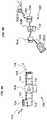
- FIG. 7A more complicated basic block diagram of a repeater system 300 is depicted in FIG. 7 .
- Three separate bidirectional amplifiers 301, 302, 303are provided. There are two separate arrays of mutually orthogonal coils; three orthogonal coils at location 'A', the X-axis coil (X), Y-axis coil (Y) and Z-axis coil (Z) as shown in the figure; and three orthogonal coils at location 'B', the Y-axis coil (Y), Z-axis coil (Z) and X-axis coil (X) as shown in the figure.
- Locations A and Bmay be separated by a distance of, for example, one meter.
- Each amplifieris connected to one coil of each array.
- the coils connected to a common amplifierare sufficiently isolated from each other (orthogonally or at large distance). In the absence of magnetic field signals, all six coils are potentially RX coils and monitored by RSSI (Radio Signal Strength Indication) circuitry (RSSI monitoring shown in the figure as RSSI1A, RSSI2A, RSSI3A, RSSI1B, RSSI2B, and RSSI3B).
- RSSIRadio Signal Strength Indication
- Logic circuitry 310(for example, BI-CMOS, TTL) is provided to decide which amplifier 301, 302, 303 is activated for a detected signal, and in which direction it is operating. The decision process is preferably based on the RSSI level. When a RSSI threshold is reached, the respective amplifier is activated and the signal is amplified to the opposite location. The respective RX coil at the opposite location will convert temporarily to a TX coil. Under this arrangement, a maximum of three coils could operate in transmission mode simultaneously.
- FIG. 8illustrates another alternative implementation, in which a single coil array (having, for example, a X-axis coil 305, a Y-axis coil 306, and a Z-axis coil 307) is shared by two directional amplifiers 330.
- Each orthogonal coil 305, 306, 307 in the arraycan be used for TX or RX as required, with coil selection (for example, through a coil selection matrix 320) made by logic circuitry 310 similarly to that of FIG. 7 .
- all three coilsare potentially RX coils and are monitored by RSSI circuitry.
- the two amplifiers 330When a RSSI threshold is reached on one of the RX coils (for example RSSIIA monitoring the X-axis coil 305), the two amplifiers 330 are activated and the signal is amplified to the other two coils 306, 307. The two other RX coils 306, 307 will convert temporarily to TX coils.
- the repeater amplifiercan be connected to the different coils with an RF feeder cable (over short or long distances).
- FIG. 9illustrates a MI repeater arrangement 400 with extension towards other communication systems 420 based upon electromagnetic (EM) wave propagation, for example Bluetooth®.
- the other communication systems 420may be optionally connected to a network 421.
- the MI radio front-endis very similar to FIG. 8 , but has an extension to an EM based communication system 420.
- EM based communication systemssuch as Bluetooth®, Wibree, a wireless LAN, cellular network (GSM) or other such system providing additional connectivity using peer-to-peer, ad-hoc or network configurations using a proprietary or non-proprietary RF protocol.
- the MI receiver amplifier 402is connected via demodulator 404 to a processing and buffering stage 406, which in turn outputs to a wireless interface 408, for example Bluetooth®, Wibree, a wireless LAN, cellular network (GSM), or other such system.
- a wireless interface 408for example Bluetooth®, Wibree, a wireless LAN, cellular network (GSM), or other such system.
- signalscan pass from the wireless EM based communication system 420, via an antenna 422 and interface 408, and processing and buffer stage 406, to modulator 410 and then to the MI transmitter amplifiers 330.
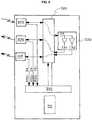
- FIG. 10illustrates another arrangement, in which bi-directional MI communications can occur with extended wireless connectivity to EM based communication systems 420 such as Bluetooth®, Wibree, a wireless LAN, cellular network (GSM), or other such system.
- Coils 305, 306are oriented to the X-axis and Y-axis respectively and are hence mutually isolated.
- Receiver amplifier 402is connected via demodulator 404 to the processing and buffering stage 406 and then to the wireless network interface 408.
- incoming signals from the external networkpass via the modulator 410 to transmitter amplifier 403 to transmitter coil 306.
- the examplesrefer to wireless RF connections, the repeater could equally be connected to a wired connection, if it is to be used in a fixed location.
- the repeatercan be powered in any suitable way, for example by battery or mains power.
- repeatercould be a separate device, or integrated within some component of the medical device system.
- a systemcomprising first and second devices, each having at least one coil and each configured to communicate using magnetic induction (MI).
- the systemfurther comprises an MI repeater comprising first and second coils configured to have the same resonance frequency as one another and to be substantially isolated from one another; and a first amplifier connected to the first and second coils and configured to receive a first signal induced in the first coil by a first magnetic field output by the first device and output, via the second coil, a second magnetic field based on the first signal so as to induce a second signal in the coil of the second device, wherein the second magnetic field is amplified relative to the first magnetic field.
- the second deviceis a medical device.
- a method of extending the range of a magnetic induction (MI) radio systemwherein a magnetic induction repeater is provided.
- MImagnetic induction
- a medical device systemincluding at least two devices which communicate using MI radio, wherein the system further includes an RF MI repeater device.
- a MI repeaterincluding a receiver coil, a transmitter coil, and an amplifier, the signal induced in the receiver coil being amplified by said amplifier, wherein the transmitter coil and the receiver coil are arranged to be highly magnetically isolated or to have a low mutual inductance.
- a MI repeaterwherein the transmitter coil and the receiver coil are mutually orthogonal.
- a MI repeaterwherein a plurality of coils are provided, and a switching device for selecting which coil is to be used.
- a MI repeaterwherein the switching device operates so that orthogonal coils are selected as the transmitter coil and receiver coil for a repeating operation.
- a MI repeater devicesaid device including a plurality of coils, amplifiers disposed between said coils, and a switching arrangement allowing selection of coils for transmission or reception of signals, a method of selecting coils for transmission, including the steps of:
- a MI repeaterwherein the repeater further includes a communications interface for an electromagnetic wave propagated system.
- a MI repeaterwherein the repeater further includes a communications interface for an electromagnetic wave propagated system.
- a MI repeaterwherein the repeater further includes a communications interface for an electromagnetic wave propagated system.
- a MI repeater deviceincluding a plurality of coils, amplifiers disposed between said coils, a switching arrangement allowing selection of coils for transmission or reception of signals, and a monitor for monitoring the incoming MI signal levels at some or all of the coils, wherein when the signal level detected by said monitor at one or said monitored coils exceeds a predetermined detection level, the signal corresponding to that signal level is amplified and the amplified signal applied to at least one other of said coils which is sufficiently isolated from the coil at which the signal was detected.
- a MI radio systemincluding a plurality of transmitters and receivers which communicate using magnetic induction radio, wherein one or more MI repeater devices are provided so as to amplify and retransmit signals from said transmitters.
Landscapes
- Engineering & Computer Science (AREA)
- Computer Networks & Wireless Communication (AREA)
- Signal Processing (AREA)
- Near-Field Transmission Systems (AREA)
Description
- The present invention relates to magnetic induction (MI) radio systems, and particularly to an MI repeater.
- Some medical devices, for example cochlear implants and hearing aids, use magnetic induction (MI) radio to communicate between a device and various associated peripheral devices. For example, it may be used to transmit data to and from a cochlear implant or hearing aid, or to communicate with a remote control. Very often the device itself has limited power, which limits the range of the MI radio communications.
- It is an object of the present invention to provide a method and device for increasing the range of a MI radio system.
CN 101 023 600 A relates to an amplification relay device which provides an amplifying repeater, which is constructed in such a manner that a ferrite core is inserted into a coil with a predetermined number of winds to increase an induced electromotive force caused by an increase in flux linkage using a time-varying magnetic field of electromagnetic waves at a position distant from various electromagnetic wave generating sources by a predetermined distance and the induction coil and a variable condenser for inducing resonance are connected to each other to increase current while reducing a resistant component existing in the induction coil to intensify and amplify the magnetic field of electromagnetic waves.- In accordance with one aspect of the present invention, a magnetic induction (MI) repeater is provided. The MI repeater comprises first and second coils configured to have the same resonance frequency and to be substantially isolated from one another, and an amplifier connected to the first and second coils and configured to receive a signal induced in the first coil by a first magnetic field and output, via the second coil, a second magnetic field based on the signal, wherein the second magnetic field is amplified relative to the first magnetic field.
- In accordance with another aspect of the present invention, a method of operating a magnetic induction (MI) repeater is provided. The MI repeater includes an amplifier connected to first and second coils that are substantially isolated from one another and are configured to have substantially the same resonance frequency. The method comprises providing to the amplifier a first signal induced in the first coil by a first magnetic field; amplifying the first signal; and outputting, via the second coil, a second magnetic field based on the first signal, wherein the second magnetic field is amplified relative to the first magnetic field.
- Aspects of the present invention will be described with reference to the accompanying figures, in which:
FIGS. 1A and 1B are schematic diagrams of aspects of the present invention;FIG. 2A is a schematic diagram of a repeater using an orthogonal coil arrangement;FIG. 2B illustrates a practical implementation of the repeater ofFIG. 2A ;FIG. 3A is another schematic diagram of a repeater using an orthogonal coil arrangement;FIG. 3B illustrates a practical implementation of the repeater ofFIG. 3A ;FIG. 4A is a schematic diagram of an alternative implementation with RX and TX coils adequately spaced from each other;FIG. 4B illustrates a practical implementation of the schematic diagram ofFIG. 4A ;FIG. 5 is a schematic diagram of a bi-directional repeater;FIG. 6 is a schematic diagram of an alternative bi-directional repeater;FIG. 7 is a schematic diagram of an alternative structure having two arrays of three coils;FIG. 8 is a schematic diagram of another alternative structure in which 3 orthogonal coils are used to provide TX and RX using switches;FIG. 9 is a schematic diagram of another variation, in which connectivity with other communication systems based upon electromagnetic wave propagation may be provided; andFIG. 10 is a schematic diagram of another variation in which connectivity with other communication systems based upon electromagnetic wave propagation may be provided.- The present invention has particular application to medical devices in which MI radio is conventionally used, for example hearing aids, cochlear implants, and the like. However, it will be understood that the underlying principle is applicable to any situation where MI radio can be applied.
- The illustrative implementation of the present invention is a MI radio repeater having substantially the same input and output frequency. The repeater works as a transparent device; the MI signal may be unmodified, for example not demodulated or modulated. This means that it only repeats the incoming signal as a copy of the original.
- The illustrative implementation may be applied to extend the communication range of a MI peripheral, for example a remote control or microphone with a MI transmitter. It may also be used to facilitate communication between a MI device placed, for example, on a bedside table and an antenna or array of antennas integrated (for example) into a bottom sheet of a bed or pillow. The repeater may also be employed to act as a buffer or amplifier, or hub, for a bilateral hearing prosthesis. Further possible applications include acting as a sniffer/monitor during a wireless fitting session, acting as a MI antenna splitter, or providing a power link (for example if there is no data stream) in order to charge the implantable battery, for example via the MI antenna array in a pillow.
- For magnetic induction radio, the quasi-static near field is used and the majority of energy is stored in the non-propagating magnetic field itself. Near-field and reactive-near field transmissions using multi-turn or single turn loop antennas can be modelled using transformer theory, although power transfer is very weak or almost inexistent. The information is coupled by the medium through the time varying magnetic field. The coupling between transmit and receive coils is very small.
- The magnetic near field of a MI system has a fast roll-off behaviour of 1/r3. The power generated by the induced RX voltage in a load rolls-off with 1/r6. Therefore it is useful to place a repeater between two devices with limited communication range.
- The repeater device according to the present implementation of the invention (control, programming and data streaming) is based on some basic principles/methods, which can be readily understood with reference to
Figure 1A . - A magnetic field (H) 102 induces a voltage over a first coil 104 (Faraday's law). The
field 102 is the MI signal transmitted by some other component of the system (not shown).Coil 104 is referred to as the receiver or RX coil. - A coil has an induced voltage that is proportional to the change of magnetic flux. This is Faraday's law, which in Maxwell's equations is written as:

- In the case of an electrical wire or coil, a voltage e(t) is generated when the magnetic flux, Φ', enclosed by that electrical wire or coil, changes.

- The voltage output of the
RX coil 104, across asuitable capacitor 103, is presented to anamplifier 106. A suitable voltage controlledamplifier 106, for example a trans-conductance amplifier as shown inFIG. 1A , converts the induced voltage signal to a current signal. The output current is then passed to asecond coil 108, which then generates an 'amplified' magnetic field (see, Ampere's circuital law and Biot-Savart law). This coil is referred to as the transmission orTX coil 108. Accordingly, an amplified form of the received, induced signal is produced. Therepeater 100 is powered by apower supply 112. The 'amplified' magnetic field in the form of a MIoutgoing signal 110 is transmitted by therepeater 100 to a remote device (not shown). - The amplifier of
FIG. 1B differs from that ofFIG. 1A asamplifier 106 ofFIG. 1B converts the induced voltage applied at its input to an output voltage signal passed over acapacitive divider 107 to asecond coil 108. - In order to avoid oscillation, the amplifier gain needs to be smaller than or equal to the isolation between the
RX coil 104 andTX coil 108. FIG. 2A illustrates a schematic diagram simple implementation of arepeater 100 with an orthogonal coil arrangement.FIG. 2B illustrates a practical implementation of the repeater ofFIG. 2A .TX coil 108 andRX coil 104 have thesame center 120 on theX-axis 114, Y-axis 116 and Z-axis 118, and are arranged orthogonally to each other (TX coil 108 in the plane formed by the Y-axis 116 and the Z-axis 118, andRX coil 104 in the plane formed by theX-axis 114 and Y-axis 116, as shown inFIG. 2B ).FIG. 3A is a schematic diagram of another implementation of arepeater 100 with an orthogonal coil arrangement, andFIG. 3B illustrates a practical implementation of the repeater ofFIG. 3A . By drawing a virtual axis or line crossing the centers of theRX coil 104 and TX coil 108 (e.g. X-axis 114), a very high isolation can be obtained when the windings of RX and TX coils 104, 108 are placed in orthogonal oriented planes with the virtual axis or line belonging to a first orthogonal plane (e.g. the plane of the RX coil windings 104) and the virtual axis as normal line (perpendicular) to a second orthogonal plane (e.g. the plane of the TX coil windings 108). Theoretically the isolation of optimal orientated and located coils is infinite. However, practically, coil imperfections will limit the isolation and thus the related permissible gain.- If the
RX coil 104 andTX coil 108 are not placed on the same axis, the geometrical shape and dimensions will define the rotation angle between the windings which has the highest isolation. It can be proven that for any point in space a rotation angle can be found having an infinite isolation betweenRX coil 104 andTX coil 108. RX and TX coils 104, 108 may be placed parallel to each other (plane-parallel on the same axis), withamplification 106 provided in between, with the RX and TX coils 104, 108 adequately spaced from each other. Since the magnetic field drops with the third power over distance, theamplifier 106 can compensate for the magnetic field attenuation. FIG. 4A is a schematic diagram of an implementation of this type, andFIG. 4B illustrates a practical implementation of the schematic diagram ofFIG. 4A . As shown in the diagram, the MI signal 102 may be received from aRemote Control Unit 900, theRX coil 104 is separated fromamplifier 106 byfeeder line 122, and similarly theamplifier 106 is separated byfeeder line 123 fromTX coil 108. TheRX coil 104 is separated from theamplifier 106 by a 30cm cable and theTX coil 108 is separated from theamplifier 106 by a 120cm cable. The amplified MI signal 110 can be transmitted, for reception by other devices (e.g. by a cochlear implant 1000).- In order to maximise the efficiency of the repeater, the RX and TX coils should be placed in resonance. Using capacitors in combination with the coils will create LC tank circuits to achieve this. The resonance may be either series or parallel resonance.
- Appropriate capacitive or inductive tapping may be employed to obtain the most appropriate repeater characteristics.
- The coils may be formed in any conventional way. They could be formed of one or multiple windings, without or with ferromagnetic or ferrimagnetic core material. A repeater setup as described above can be used for uni- or bi-directional communication links on the same frequency.
- Two orthogonal coils made of 20 copper windings each having a diameter of 10 mm is a very suitable antenna system for a compact repeater working at 10MHz. Using a ferrite core having a relative permeability of 100 could practically reduce the winding diameter by a factor of 10 or more.
- The detection of the presence of a MI signal by RSSI (Radio Signal Strength Indication) could activate the amplifier, in order to minimise power consumption. Such a detection circuit could also be used to determine the direction of communication (uplink/downlink) in case of an implementation having common RX/TX coils or amplifiers, as will be explained below with reference to examples. In a preferred implementation, the resonance frequencies of the RX and TX coils are the same. A complete bidirectional repeater including common antennas can then be made very compactly.
- A repeater amplifying electromagnetic (EM) wave signals on a common frequency with high gain could easily oscillate due to an unstable transmission path loss. If the path loss becomes equal to or lower than the gain of the amplifier, oscillation readily occurs. Such instability in signal path loss could be caused by reflections (multi-path), conduction or absorptions by objects or persons in the vicinity, or other wave propagation related factors. Therefore, the RX and TX antenna are placed far from each other (typically extended with coaxial cables) for an EM field RF repeater arrangement.
- The magnetic fields used for MI (magnetic induction) radio do not suffer from these reflections and instabilities. High isolations are obtained even at short distances by placing the RX and TX coils in mutually orthogonal positions.
- Utilizing a MI repeater such as described allows, at its simplest, the range of MI radio systems to be increased. This may be for extending the range of peripheral devices, for example remote controls, microphones, or other elements of the medical device system. It may be used to extend the range for wireless device programming over MI radio. It may assist in enabling communications between the sides of a bilateral hearing prosthesis. It may act as an antenna splitter, and additionally provide links to other wireless or wired systems.
- The TX coil or coils of the repeater could provide a power link if there is no data stream, for example to charge the implantable battery where the implantable device includes a battery. In this form, the repeater could be implemented as, for example, a MI antenna array in a pillow or similar arrangement.
- The output level of the amplifier can be controlled or limited using an automatic level control (ALC) system. The ALC will reduce the gain of the amplifier where strong incoming signal levels are detected. Incoming signal levels could easily vary from 1001aV (microvolt) to 100mV. This would require a very linear amplifier with a 60dB dynamic range. An ALC could reduce the dynamic range requirement by 30dB thereby decreasing the total power consumption of such an amplifier.
FIG. 5 illustrates a simplebi-directional implementation 200 of the present invention. In this arrangement, acommon power supply 112 is used. Separate pairs of RX and TX coils are provided for each direction of communication. In one pair,RX coil 204 is (for example) oriented to theX-axis 114, andRX coil 203 is oriented to the Z-axis 118. Both TX coils 207, 208 are oriented to the Y-axis 116. As such, the RX coils 203, 204 are orthogonal to the TX coils 207, 208, and hence a very high isolation is achieved. There is also orthogonality between each of the coils located at the same side of therepeater 200. This type of arrangement can be employed with either a common or separate operating frequencies.FIG. 6 illustrates an arrangement similar to that ofFIG. 5 , with a similar orthogonal coil arrangement. However, it uses a more sophisticated amplifier arrangement. In addition toseparate amplifiers amplifiers RX coil 204,bandpass filter 210 is provided before the signal reachesamplifier 205. Afurther bandpass filter 211 is provided betweenamplifier 205 andTX coil 207.- The bandpass filters are used to improve on frequency channel selectivity of the repeater. A higher selectivity is advantageous if adjacent channels or adjacent frequency interference needs to be filtered out. Filtering the amplifier's output improves also on EMC compatibility. If the uplink and downlink amplifier chain of the repeater operate at different frequency channels, the receiver and transmitter coils of the uplink and downlink could even reside on the same axis.
- A more complicated basic block diagram of a
repeater system 300 is depicted inFIG. 7 . Three separatebidirectional amplifiers - Logic circuitry 310 (for example, BI-CMOS, TTL) is provided to decide which
amplifier FIG. 8 illustrates another alternative implementation, in which a single coil array (having, for example, aX-axis coil 305, a Y-axis coil 306, and a Z-axis coil 307) is shared by twodirectional amplifiers 330. Eachorthogonal coil logic circuitry 310 similarly to that ofFIG. 7 . In the absence of magnetic field signals, all three coils are potentially RX coils and are monitored by RSSI circuitry. When a RSSI threshold is reached on one of the RX coils (for example RSSIIA monitoring the X-axis coil 305), the twoamplifiers 330 are activated and the signal is amplified to the other twocoils - A maximum of two coils could operate in transmission mode simultaneously under this arrangement. The repeater amplifier can be connected to the different coils with an RF feeder cable (over short or long distances).
FIG. 9 illustrates aMI repeater arrangement 400 with extension towardsother communication systems 420 based upon electromagnetic (EM) wave propagation, for example Bluetooth®. Theother communication systems 420 may be optionally connected to anetwork 421. The MI radio front-end is very similar toFIG. 8 , but has an extension to an EM basedcommunication system 420. EM based communication systems such as Bluetooth®, Wibree, a wireless LAN, cellular network (GSM) or other such system providing additional connectivity using peer-to-peer, ad-hoc or network configurations using a proprietary or non-proprietary RF protocol. TheMI receiver amplifier 402 is connected viademodulator 404 to a processing andbuffering stage 406, which in turn outputs to awireless interface 408, for example Bluetooth®, Wibree, a wireless LAN, cellular network (GSM), or other such system. Similarly, signals can pass from the wireless EM basedcommunication system 420, via anantenna 422 andinterface 408, and processing andbuffer stage 406, to modulator 410 and then to theMI transmitter amplifiers 330.FIG. 10 illustrates another arrangement, in which bi-directional MI communications can occur with extended wireless connectivity to EM basedcommunication systems 420 such as Bluetooth®, Wibree, a wireless LAN, cellular network (GSM), or other such system.Coils Receiver amplifier 402 is connected viademodulator 404 to the processing andbuffering stage 406 and then to thewireless network interface 408. Similarly, incoming signals from the external network pass via themodulator 410 totransmitter amplifier 403 totransmitter coil 306. It is noted that whilst the examples refer to wireless RF connections, the repeater could equally be connected to a wired connection, if it is to be used in a fixed location.- The repeater can be powered in any suitable way, for example by battery or mains power.
- It will be understood that the repeater could be a separate device, or integrated within some component of the medical device system.
- In aspects of the present invention, a system is provided. The system comprises first and second devices, each having at least one coil and each configured to communicate using magnetic induction (MI). The system further comprises an MI repeater comprising first and second coils configured to have the same resonance frequency as one another and to be substantially isolated from one another; and a first amplifier connected to the first and second coils and configured to receive a first signal induced in the first coil by a first magnetic field output by the first device and output, via the second coil, a second magnetic field based on the first signal so as to induce a second signal in the coil of the second device, wherein the second magnetic field is amplified relative to the first magnetic field. In aspects of the present invention, the second device is a medical device.
- In an aspect of the present invention, a method of extending the range of a magnetic induction (MI) radio system, wherein a magnetic induction repeater is provided.
- In an aspect of the present invention, a medical device system, including at least two devices which communicate using MI radio, wherein the system further includes an RF MI repeater device.
- In an aspect of the present invention, a MI repeater, including a receiver coil, a transmitter coil, and an amplifier, the signal induced in the receiver coil being amplified by said amplifier, wherein the transmitter coil and the receiver coil are arranged to be highly magnetically isolated or to have a low mutual inductance.
- In an aspect of the present invention, a MI repeater wherein the transmitter coil and the receiver coil are mutually orthogonal.
- In an aspect of the present invention, a MI repeater wherein a plurality of coils are provided, and a switching device for selecting which coil is to be used.
- In an aspect of the present invention, a MI repeater wherein the switching device operates so that orthogonal coils are selected as the transmitter coil and receiver coil for a repeating operation.
- In an aspect of the present invention, a MI repeater device, said device including a plurality of coils, amplifiers disposed between said coils, and a switching arrangement allowing selection of coils for transmission or reception of signals, a method of selecting coils for transmission, including the steps of:
- a. monitoring of the incoming MI signal levels at some or all of the coils;
- b. determining whether the signal level at each monitored coil exceeds a predetermined detection level;
- c. if the level is exceeded, amplifying the corresponding signal, and applying the amplified signal to at least one coil which is sufficiently isolated from the coil at which the signal was detected.
- In an aspect of the present invention, a MI repeater wherein the repeater further includes a communications interface for an electromagnetic wave propagated system.
- In an aspect of the present invention, a MI repeater wherein the repeater further includes a communications interface for an electromagnetic wave propagated system.
- In an aspect of the present invention, a MI repeater wherein the repeater further includes a communications interface for an electromagnetic wave propagated system.
- In an aspect of the present invention, a MI repeater device, including a plurality of coils, amplifiers disposed between said coils, a switching arrangement allowing selection of coils for transmission or reception of signals, and a monitor for monitoring the incoming MI signal levels at some or all of the coils, wherein when the signal level detected by said monitor at one or said monitored coils exceeds a predetermined detection level, the signal corresponding to that signal level is amplified and the amplified signal applied to at least one other of said coils which is sufficiently isolated from the coil at which the signal was detected.
- In an aspect of the present invention, a MI radio system, including a plurality of transmitters and receivers which communicate using magnetic induction radio, wherein one or more MI repeater devices are provided so as to amplify and retransmit signals from said transmitters.


Claims (15)
- A magnetic induction (MI) repeater (100, 200)characterized by:first and second coils (104, 108, 204, 207) configured to have the same resonance frequency and to be substantially isolated from one another; andan amplifier (106, 205) connected to the first and second coils (104, 108, 204, 207) and configured to receive a signal induced in the first coil (104, 204) by a first magnetic field (102) and output, via the second coil (108, 207), a second magnetic field (110) based on the signal,wherein the second magnetic field (110) is amplified relative to the first magnetic field (102).
- The repeater (100) of claim 1, wherein the first and second coils (104, 108) have the same center (120).
- The repeater (100) of claim 1, wherein the respective centers of the first and second coils (104, 108) are disposed on the same axis (114).
- The repeater (100) of any of the preceding claims, wherein the first coil (104) is disposed in a first plane and the second coil (108) is disposed in a second plane orthogonal to the first plane.
- The repeater (100, 200) of any of the preceding claims, further comprising:a detection circuit configured to activate the amplifier (106, 205) upon detecting the presence of an MI signal via at least one of the first and second coils (104, 108, 204, 207).
- The repeater (100, 200) of claim 5, wherein the detection circuit comprises radio signal strength indication (RSSI) circuitry monitoring the first and second coils (104, 108, 204, 207).
- The repeater (200) of any one of claims 1 and 4-6, wherein the amplifier (205) is further configured to receive a second signal induced in the second coil (207) by a third magnetic field and output, based on the second signal, a fourth magnetic field via the first coil (204), wherein the fourth magnetic field is amplified relative to the third magnetic field.
- The repeater (200) of any one of claims 1 and 4-6, further comprising:third and fourth coils (203, 208) configured to have the same resonance frequency as one another and to be substantially isolated from one another; anda second amplifier (206) connected to the third and fourth coils (203, 208).
- The repeater (200) of claim 8, wherein the RSSI circuitry further monitors the third and fourth coils (203, 208), the repeater (200) further comprising:logic circuitry configured to activate one or more of the first and second amplifiers (205, 206) upon detection of an MI signal via one of the first, second, third and fourth coils (203, 208).
- The repeater (200) of claim 8 or 9, wherein the third and fourth coils (203, 208) are mutually orthogonal.
- A method of operating a magnetic induction (MI) repeater (100, 200) including an amplifier (106, 205) connected to first and second coils (104, 108, 204, 207) that are substantially isolated from one another and are configured to have the same resonance frequency, the method comprising:providing to the amplifier (106, 205) a first signal induced in the first coil (104, 204) by a first magnetic field (102); andoutputting, via the second coil (108, 207), a second magnetic field (110) based on the first signal using the amplifier (106, 205), wherein the second magnetic field (110) is amplified relative to the first magnetic field (102).
- The method of claim 11, wherein the first and second coils (104, 108, 204, 207) have the same center (120).
- The method of any of the preceding claims, wherein the first coil (104, 204) is disposed in a first plane and the second coil (108, 207) is disposed in a second plane orthogonal to the first plane.
- The method of any of the preceding claims, further comprising:activating the amplifier (106, 205) upon detecting the presence of an MI signal via at least one of the first and second coils (104, 108, 204, 207).
- The method of any of the preceding claims, further comprising:providing to the amplifier (106, 205) a second signal induced in the second coil (108,207) by a third magnetic field; andoutputting, via the first coil (104, 204), a fourth magnetic field based on the second signal using the amplifier (106, 205), wherein the fourth magnetic field is amplified relative to the third magnetic field.
Applications Claiming Priority (2)
| Application Number | Priority Date | Filing Date | Title |
|---|---|---|---|
| AU2008902082AAU2008902082A0 (en) | 2008-04-28 | Magnetic Inductive systems and devices | |
| PCT/AU2009/000523WO2009132383A1 (en) | 2008-04-28 | 2009-04-28 | Magnetic inductive systems and devices |
Publications (3)
| Publication Number | Publication Date |
|---|---|
| EP2274837A1 EP2274837A1 (en) | 2011-01-19 |
| EP2274837A4 EP2274837A4 (en) | 2013-07-03 |
| EP2274837B1true EP2274837B1 (en) | 2018-01-10 |
Family
ID=41254692
Family Applications (1)
| Application Number | Title | Priority Date | Filing Date |
|---|---|---|---|
| EP09737533.1ANot-in-forceEP2274837B1 (en) | 2008-04-28 | 2009-04-28 | Magnetic inductive systems and devices |
Country Status (4)
| Country | Link |
|---|---|
| US (2) | US8457547B2 (en) |
| EP (1) | EP2274837B1 (en) |
| DK (1) | DK2274837T3 (en) |
| WO (1) | WO2009132383A1 (en) |
Families Citing this family (233)
| Publication number | Priority date | Publication date | Assignee | Title |
|---|---|---|---|---|
| US8115448B2 (en) | 2007-06-01 | 2012-02-14 | Michael Sasha John | Systems and methods for wireless power |
| US9421388B2 (en) | 2007-06-01 | 2016-08-23 | Witricity Corporation | Power generation for implantable devices |
| US8772973B2 (en) | 2008-09-27 | 2014-07-08 | Witricity Corporation | Integrated resonator-shield structures |
| US8901779B2 (en) | 2008-09-27 | 2014-12-02 | Witricity Corporation | Wireless energy transfer with resonator arrays for medical applications |
| US8692412B2 (en) | 2008-09-27 | 2014-04-08 | Witricity Corporation | Temperature compensation in a wireless transfer system |
| US9160203B2 (en) | 2008-09-27 | 2015-10-13 | Witricity Corporation | Wireless powered television |
| US8907531B2 (en)* | 2008-09-27 | 2014-12-09 | Witricity Corporation | Wireless energy transfer with variable size resonators for medical applications |
| US9246336B2 (en) | 2008-09-27 | 2016-01-26 | Witricity Corporation | Resonator optimizations for wireless energy transfer |
| US8922066B2 (en) | 2008-09-27 | 2014-12-30 | Witricity Corporation | Wireless energy transfer with multi resonator arrays for vehicle applications |
| US8957549B2 (en) | 2008-09-27 | 2015-02-17 | Witricity Corporation | Tunable wireless energy transfer for in-vehicle applications |
| US9744858B2 (en) | 2008-09-27 | 2017-08-29 | Witricity Corporation | System for wireless energy distribution in a vehicle |
| US9601261B2 (en) | 2008-09-27 | 2017-03-21 | Witricity Corporation | Wireless energy transfer using repeater resonators |
| US9396867B2 (en) | 2008-09-27 | 2016-07-19 | Witricity Corporation | Integrated resonator-shield structures |
| US9544683B2 (en) | 2008-09-27 | 2017-01-10 | Witricity Corporation | Wirelessly powered audio devices |
| US8912687B2 (en) | 2008-09-27 | 2014-12-16 | Witricity Corporation | Secure wireless energy transfer for vehicle applications |
| US9515494B2 (en) | 2008-09-27 | 2016-12-06 | Witricity Corporation | Wireless power system including impedance matching network |
| US9106203B2 (en) | 2008-09-27 | 2015-08-11 | Witricity Corporation | Secure wireless energy transfer in medical applications |
| US9184595B2 (en) | 2008-09-27 | 2015-11-10 | Witricity Corporation | Wireless energy transfer in lossy environments |
| US8598743B2 (en) | 2008-09-27 | 2013-12-03 | Witricity Corporation | Resonator arrays for wireless energy transfer |
| US8933594B2 (en) | 2008-09-27 | 2015-01-13 | Witricity Corporation | Wireless energy transfer for vehicles |
| US9105959B2 (en) | 2008-09-27 | 2015-08-11 | Witricity Corporation | Resonator enclosure |
| US8643326B2 (en) | 2008-09-27 | 2014-02-04 | Witricity Corporation | Tunable wireless energy transfer systems |
| US8963488B2 (en) | 2008-09-27 | 2015-02-24 | Witricity Corporation | Position insensitive wireless charging |
| US8497601B2 (en) | 2008-09-27 | 2013-07-30 | Witricity Corporation | Wireless energy transfer converters |
| US9577436B2 (en) | 2008-09-27 | 2017-02-21 | Witricity Corporation | Wireless energy transfer for implantable devices |
| US8669676B2 (en) | 2008-09-27 | 2014-03-11 | Witricity Corporation | Wireless energy transfer across variable distances using field shaping with magnetic materials to improve the coupling factor |
| US8937408B2 (en) | 2008-09-27 | 2015-01-20 | Witricity Corporation | Wireless energy transfer for medical applications |
| US20100259110A1 (en)* | 2008-09-27 | 2010-10-14 | Kurs Andre B | Resonator optimizations for wireless energy transfer |
| US8947186B2 (en) | 2008-09-27 | 2015-02-03 | Witricity Corporation | Wireless energy transfer resonator thermal management |
| US9035499B2 (en) | 2008-09-27 | 2015-05-19 | Witricity Corporation | Wireless energy transfer for photovoltaic panels |
| US9065423B2 (en) | 2008-09-27 | 2015-06-23 | Witricity Corporation | Wireless energy distribution system |
| US8901778B2 (en) | 2008-09-27 | 2014-12-02 | Witricity Corporation | Wireless energy transfer with variable size resonators for implanted medical devices |
| US9601270B2 (en) | 2008-09-27 | 2017-03-21 | Witricity Corporation | Low AC resistance conductor designs |
| US9601266B2 (en) | 2008-09-27 | 2017-03-21 | Witricity Corporation | Multiple connected resonators with a single electronic circuit |
| US8946938B2 (en) | 2008-09-27 | 2015-02-03 | Witricity Corporation | Safety systems for wireless energy transfer in vehicle applications |
| US8723366B2 (en) | 2008-09-27 | 2014-05-13 | Witricity Corporation | Wireless energy transfer resonator enclosures |
| US9093853B2 (en) | 2008-09-27 | 2015-07-28 | Witricity Corporation | Flexible resonator attachment |
| US9318922B2 (en) | 2008-09-27 | 2016-04-19 | Witricity Corporation | Mechanically removable wireless power vehicle seat assembly |
| US8928276B2 (en) | 2008-09-27 | 2015-01-06 | Witricity Corporation | Integrated repeaters for cell phone applications |
| US8482158B2 (en) | 2008-09-27 | 2013-07-09 | Witricity Corporation | Wireless energy transfer using variable size resonators and system monitoring |
| US9602168B2 (en) | 2010-08-31 | 2017-03-21 | Witricity Corporation | Communication in wireless energy transfer systems |
| US20120203620A1 (en) | 2010-11-08 | 2012-08-09 | Douglas Howard Dobyns | Techniques For Wireless Communication Of Proximity Based Marketing |
| US8929809B2 (en) | 2011-03-22 | 2015-01-06 | Radeum, Inc. | Techniques for wireless communication of proximity based content |
| US8880100B2 (en) | 2011-03-23 | 2014-11-04 | Radium, Inc. | Proximity based social networking |
| US9948145B2 (en) | 2011-07-08 | 2018-04-17 | Witricity Corporation | Wireless power transfer for a seat-vest-helmet system |
| CN108110907B (en) | 2011-08-04 | 2022-08-02 | 韦特里西提公司 | Tunable wireless power supply architecture |
| EP2754222B1 (en) | 2011-09-09 | 2015-11-18 | Witricity Corporation | Foreign object detection in wireless energy transfer systems |
| US20130062966A1 (en) | 2011-09-12 | 2013-03-14 | Witricity Corporation | Reconfigurable control architectures and algorithms for electric vehicle wireless energy transfer systems |
| US9318257B2 (en) | 2011-10-18 | 2016-04-19 | Witricity Corporation | Wireless energy transfer for packaging |
| CA2853824A1 (en) | 2011-11-04 | 2013-05-10 | Witricity Corporation | Wireless energy transfer modeling tool |
| JP2015508987A (en) | 2012-01-26 | 2015-03-23 | ワイトリシティ コーポレーションWitricity Corporation | Wireless energy transmission with reduced field |
| US9343922B2 (en) | 2012-06-27 | 2016-05-17 | Witricity Corporation | Wireless energy transfer for rechargeable batteries |
| US9287607B2 (en) | 2012-07-31 | 2016-03-15 | Witricity Corporation | Resonator fine tuning |
| WO2014038265A1 (en)* | 2012-09-05 | 2014-03-13 | ルネサスエレクトロニクス株式会社 | Non-contact charging device, and non-contact power supply system using same |
| US9595378B2 (en) | 2012-09-19 | 2017-03-14 | Witricity Corporation | Resonator enclosure |
| EP2909912B1 (en) | 2012-10-19 | 2022-08-10 | WiTricity Corporation | Foreign object detection in wireless energy transfer systems |
| US9842684B2 (en) | 2012-11-16 | 2017-12-12 | Witricity Corporation | Systems and methods for wireless power system with improved performance and/or ease of use |
| US10009065B2 (en) | 2012-12-05 | 2018-06-26 | At&T Intellectual Property I, L.P. | Backhaul link for distributed antenna system |
| US9113347B2 (en) | 2012-12-05 | 2015-08-18 | At&T Intellectual Property I, Lp | Backhaul link for distributed antenna system |
| US9035844B2 (en)* | 2013-05-17 | 2015-05-19 | Medtronic, Inc. | Telemetry extension cable |
| US9525524B2 (en) | 2013-05-31 | 2016-12-20 | At&T Intellectual Property I, L.P. | Remote distributed antenna system |
| US9999038B2 (en) | 2013-05-31 | 2018-06-12 | At&T Intellectual Property I, L.P. | Remote distributed antenna system |
| US9857821B2 (en) | 2013-08-14 | 2018-01-02 | Witricity Corporation | Wireless power transfer frequency adjustment |
| US8897697B1 (en) | 2013-11-06 | 2014-11-25 | At&T Intellectual Property I, Lp | Millimeter-wave surface-wave communications |
| US9209902B2 (en) | 2013-12-10 | 2015-12-08 | At&T Intellectual Property I, L.P. | Quasi-optical coupler |
| US9780573B2 (en) | 2014-02-03 | 2017-10-03 | Witricity Corporation | Wirelessly charged battery system |
| US9952266B2 (en) | 2014-02-14 | 2018-04-24 | Witricity Corporation | Object detection for wireless energy transfer systems |
| US9842687B2 (en) | 2014-04-17 | 2017-12-12 | Witricity Corporation | Wireless power transfer systems with shaped magnetic components |
| US9892849B2 (en) | 2014-04-17 | 2018-02-13 | Witricity Corporation | Wireless power transfer systems with shield openings |
| US9837860B2 (en) | 2014-05-05 | 2017-12-05 | Witricity Corporation | Wireless power transmission systems for elevators |
| JP2017518018A (en) | 2014-05-07 | 2017-06-29 | ワイトリシティ コーポレーションWitricity Corporation | Foreign object detection in wireless energy transmission systems |
| US9954375B2 (en) | 2014-06-20 | 2018-04-24 | Witricity Corporation | Wireless power transfer systems for surfaces |
| US10574091B2 (en) | 2014-07-08 | 2020-02-25 | Witricity Corporation | Enclosures for high power wireless power transfer systems |
| CN107258046B (en) | 2014-07-08 | 2020-07-17 | 无线电力公司 | Resonator equalization in wireless power transfer systems |
| US9692101B2 (en) | 2014-08-26 | 2017-06-27 | At&T Intellectual Property I, L.P. | Guided wave couplers for coupling electromagnetic waves between a waveguide surface and a surface of a wire |
| US9780837B2 (en) | 2014-08-29 | 2017-10-03 | Freelinc Technologies | Spatially enabled secure communications |
| US9768833B2 (en) | 2014-09-15 | 2017-09-19 | At&T Intellectual Property I, L.P. | Method and apparatus for sensing a condition in a transmission medium of electromagnetic waves |
| US10063280B2 (en) | 2014-09-17 | 2018-08-28 | At&T Intellectual Property I, L.P. | Monitoring and mitigating conditions in a communication network |
| US9615269B2 (en) | 2014-10-02 | 2017-04-04 | At&T Intellectual Property I, L.P. | Method and apparatus that provides fault tolerance in a communication network |
| US9685992B2 (en) | 2014-10-03 | 2017-06-20 | At&T Intellectual Property I, L.P. | Circuit panel network and methods thereof |
| US9503189B2 (en) | 2014-10-10 | 2016-11-22 | At&T Intellectual Property I, L.P. | Method and apparatus for arranging communication sessions in a communication system |
| US9973299B2 (en) | 2014-10-14 | 2018-05-15 | At&T Intellectual Property I, L.P. | Method and apparatus for adjusting a mode of communication in a communication network |
| US9762289B2 (en) | 2014-10-14 | 2017-09-12 | At&T Intellectual Property I, L.P. | Method and apparatus for transmitting or receiving signals in a transportation system |
| US9780834B2 (en) | 2014-10-21 | 2017-10-03 | At&T Intellectual Property I, L.P. | Method and apparatus for transmitting electromagnetic waves |
| US9312919B1 (en) | 2014-10-21 | 2016-04-12 | At&T Intellectual Property I, Lp | Transmission device with impairment compensation and methods for use therewith |
| US9577306B2 (en) | 2014-10-21 | 2017-02-21 | At&T Intellectual Property I, L.P. | Guided-wave transmission device and methods for use therewith |
| US9627768B2 (en) | 2014-10-21 | 2017-04-18 | At&T Intellectual Property I, L.P. | Guided-wave transmission device with non-fundamental mode propagation and methods for use therewith |
| US9653770B2 (en) | 2014-10-21 | 2017-05-16 | At&T Intellectual Property I, L.P. | Guided wave coupler, coupling module and methods for use therewith |
| US9520945B2 (en) | 2014-10-21 | 2016-12-13 | At&T Intellectual Property I, L.P. | Apparatus for providing communication services and methods thereof |
| US9769020B2 (en) | 2014-10-21 | 2017-09-19 | At&T Intellectual Property I, L.P. | Method and apparatus for responding to events affecting communications in a communication network |
| US9954287B2 (en) | 2014-11-20 | 2018-04-24 | At&T Intellectual Property I, L.P. | Apparatus for converting wireless signals and electromagnetic waves and methods thereof |
| US9654173B2 (en) | 2014-11-20 | 2017-05-16 | At&T Intellectual Property I, L.P. | Apparatus for powering a communication device and methods thereof |
| US10009067B2 (en) | 2014-12-04 | 2018-06-26 | At&T Intellectual Property I, L.P. | Method and apparatus for configuring a communication interface |
| US9544006B2 (en) | 2014-11-20 | 2017-01-10 | At&T Intellectual Property I, L.P. | Transmission device with mode division multiplexing and methods for use therewith |
| US9742462B2 (en) | 2014-12-04 | 2017-08-22 | At&T Intellectual Property I, L.P. | Transmission medium and communication interfaces and methods for use therewith |
| US10243784B2 (en) | 2014-11-20 | 2019-03-26 | At&T Intellectual Property I, L.P. | System for generating topology information and methods thereof |
| US9997819B2 (en) | 2015-06-09 | 2018-06-12 | At&T Intellectual Property I, L.P. | Transmission medium and method for facilitating propagation of electromagnetic waves via a core |
| US9800327B2 (en) | 2014-11-20 | 2017-10-24 | At&T Intellectual Property I, L.P. | Apparatus for controlling operations of a communication device and methods thereof |
| US9461706B1 (en) | 2015-07-31 | 2016-10-04 | At&T Intellectual Property I, Lp | Method and apparatus for exchanging communication signals |
| US10340573B2 (en) | 2016-10-26 | 2019-07-02 | At&T Intellectual Property I, L.P. | Launcher with cylindrical coupling device and methods for use therewith |
| US9680670B2 (en) | 2014-11-20 | 2017-06-13 | At&T Intellectual Property I, L.P. | Transmission device with channel equalization and control and methods for use therewith |
| US10164685B2 (en) | 2014-12-31 | 2018-12-25 | Freelinc Technologies Inc. | Spatially aware wireless network |
| US9843217B2 (en) | 2015-01-05 | 2017-12-12 | Witricity Corporation | Wireless energy transfer for wearables |
| US10144036B2 (en) | 2015-01-30 | 2018-12-04 | At&T Intellectual Property I, L.P. | Method and apparatus for mitigating interference affecting a propagation of electromagnetic waves guided by a transmission medium |
| US9876570B2 (en) | 2015-02-20 | 2018-01-23 | At&T Intellectual Property I, Lp | Guided-wave transmission device with non-fundamental mode propagation and methods for use therewith |
| US9749013B2 (en) | 2015-03-17 | 2017-08-29 | At&T Intellectual Property I, L.P. | Method and apparatus for reducing attenuation of electromagnetic waves guided by a transmission medium |
| US10224981B2 (en) | 2015-04-24 | 2019-03-05 | At&T Intellectual Property I, Lp | Passive electrical coupling device and methods for use therewith |
| US9705561B2 (en) | 2015-04-24 | 2017-07-11 | At&T Intellectual Property I, L.P. | Directional coupling device and methods for use therewith |
| US9793954B2 (en) | 2015-04-28 | 2017-10-17 | At&T Intellectual Property I, L.P. | Magnetic coupling device and methods for use therewith |
| US9948354B2 (en) | 2015-04-28 | 2018-04-17 | At&T Intellectual Property I, L.P. | Magnetic coupling device with reflective plate and methods for use therewith |
| US9748626B2 (en) | 2015-05-14 | 2017-08-29 | At&T Intellectual Property I, L.P. | Plurality of cables having different cross-sectional shapes which are bundled together to form a transmission medium |
| US9871282B2 (en) | 2015-05-14 | 2018-01-16 | At&T Intellectual Property I, L.P. | At least one transmission medium having a dielectric surface that is covered at least in part by a second dielectric |
| US9490869B1 (en) | 2015-05-14 | 2016-11-08 | At&T Intellectual Property I, L.P. | Transmission medium having multiple cores and methods for use therewith |
| US10650940B2 (en) | 2015-05-15 | 2020-05-12 | At&T Intellectual Property I, L.P. | Transmission medium having a conductive material and methods for use therewith |
| US9917341B2 (en) | 2015-05-27 | 2018-03-13 | At&T Intellectual Property I, L.P. | Apparatus and method for launching electromagnetic waves and for modifying radial dimensions of the propagating electromagnetic waves |
| US9912381B2 (en) | 2015-06-03 | 2018-03-06 | At&T Intellectual Property I, Lp | Network termination and methods for use therewith |
| US10812174B2 (en) | 2015-06-03 | 2020-10-20 | At&T Intellectual Property I, L.P. | Client node device and methods for use therewith |
| US9866309B2 (en) | 2015-06-03 | 2018-01-09 | At&T Intellectual Property I, Lp | Host node device and methods for use therewith |
| US10103801B2 (en) | 2015-06-03 | 2018-10-16 | At&T Intellectual Property I, L.P. | Host node device and methods for use therewith |
| US9913139B2 (en) | 2015-06-09 | 2018-03-06 | At&T Intellectual Property I, L.P. | Signal fingerprinting for authentication of communicating devices |
| US10142086B2 (en) | 2015-06-11 | 2018-11-27 | At&T Intellectual Property I, L.P. | Repeater and methods for use therewith |
| US9608692B2 (en) | 2015-06-11 | 2017-03-28 | At&T Intellectual Property I, L.P. | Repeater and methods for use therewith |
| US9820146B2 (en) | 2015-06-12 | 2017-11-14 | At&T Intellectual Property I, L.P. | Method and apparatus for authentication and identity management of communicating devices |
| US9667317B2 (en) | 2015-06-15 | 2017-05-30 | At&T Intellectual Property I, L.P. | Method and apparatus for providing security using network traffic adjustments |
| US9640850B2 (en) | 2015-06-25 | 2017-05-02 | At&T Intellectual Property I, L.P. | Methods and apparatus for inducing a non-fundamental wave mode on a transmission medium |
| US9509415B1 (en) | 2015-06-25 | 2016-11-29 | At&T Intellectual Property I, L.P. | Methods and apparatus for inducing a fundamental wave mode on a transmission medium |
| US9865911B2 (en) | 2015-06-25 | 2018-01-09 | At&T Intellectual Property I, L.P. | Waveguide system for slot radiating first electromagnetic waves that are combined into a non-fundamental wave mode second electromagnetic wave on a transmission medium |
| US10170840B2 (en) | 2015-07-14 | 2019-01-01 | At&T Intellectual Property I, L.P. | Apparatus and methods for sending or receiving electromagnetic signals |
| US10033107B2 (en) | 2015-07-14 | 2018-07-24 | At&T Intellectual Property I, L.P. | Method and apparatus for coupling an antenna to a device |
| US9853342B2 (en) | 2015-07-14 | 2017-12-26 | At&T Intellectual Property I, L.P. | Dielectric transmission medium connector and methods for use therewith |
| US10205655B2 (en) | 2015-07-14 | 2019-02-12 | At&T Intellectual Property I, L.P. | Apparatus and methods for communicating utilizing an antenna array and multiple communication paths |
| US10148016B2 (en) | 2015-07-14 | 2018-12-04 | At&T Intellectual Property I, L.P. | Apparatus and methods for communicating utilizing an antenna array |
| US10033108B2 (en) | 2015-07-14 | 2018-07-24 | At&T Intellectual Property I, L.P. | Apparatus and methods for generating an electromagnetic wave having a wave mode that mitigates interference |
| US9882257B2 (en) | 2015-07-14 | 2018-01-30 | At&T Intellectual Property I, L.P. | Method and apparatus for launching a wave mode that mitigates interference |
| US9722318B2 (en) | 2015-07-14 | 2017-08-01 | At&T Intellectual Property I, L.P. | Method and apparatus for coupling an antenna to a device |
| US10341142B2 (en) | 2015-07-14 | 2019-07-02 | At&T Intellectual Property I, L.P. | Apparatus and methods for generating non-interfering electromagnetic waves on an uninsulated conductor |
| US9847566B2 (en) | 2015-07-14 | 2017-12-19 | At&T Intellectual Property I, L.P. | Method and apparatus for adjusting a field of a signal to mitigate interference |
| US10320586B2 (en) | 2015-07-14 | 2019-06-11 | At&T Intellectual Property I, L.P. | Apparatus and methods for generating non-interfering electromagnetic waves on an insulated transmission medium |
| US9628116B2 (en) | 2015-07-14 | 2017-04-18 | At&T Intellectual Property I, L.P. | Apparatus and methods for transmitting wireless signals |
| US10044409B2 (en) | 2015-07-14 | 2018-08-07 | At&T Intellectual Property I, L.P. | Transmission medium and methods for use therewith |
| US9836957B2 (en) | 2015-07-14 | 2017-12-05 | At&T Intellectual Property I, L.P. | Method and apparatus for communicating with premises equipment |
| US9793951B2 (en) | 2015-07-15 | 2017-10-17 | At&T Intellectual Property I, L.P. | Method and apparatus for launching a wave mode that mitigates interference |
| US10090606B2 (en) | 2015-07-15 | 2018-10-02 | At&T Intellectual Property I, L.P. | Antenna system with dielectric array and methods for use therewith |
| US9608740B2 (en) | 2015-07-15 | 2017-03-28 | At&T Intellectual Property I, L.P. | Method and apparatus for launching a wave mode that mitigates interference |
| US9749053B2 (en) | 2015-07-23 | 2017-08-29 | At&T Intellectual Property I, L.P. | Node device, repeater and methods for use therewith |
| US9871283B2 (en) | 2015-07-23 | 2018-01-16 | At&T Intellectual Property I, Lp | Transmission medium having a dielectric core comprised of plural members connected by a ball and socket configuration |
| US10784670B2 (en) | 2015-07-23 | 2020-09-22 | At&T Intellectual Property I, L.P. | Antenna support for aligning an antenna |
| US9948333B2 (en) | 2015-07-23 | 2018-04-17 | At&T Intellectual Property I, L.P. | Method and apparatus for wireless communications to mitigate interference |
| US9912027B2 (en) | 2015-07-23 | 2018-03-06 | At&T Intellectual Property I, L.P. | Method and apparatus for exchanging communication signals |
| US9735833B2 (en) | 2015-07-31 | 2017-08-15 | At&T Intellectual Property I, L.P. | Method and apparatus for communications management in a neighborhood network |
| US9967173B2 (en) | 2015-07-31 | 2018-05-08 | At&T Intellectual Property I, L.P. | Method and apparatus for authentication and identity management of communicating devices |
| US10020587B2 (en) | 2015-07-31 | 2018-07-10 | At&T Intellectual Property I, L.P. | Radial antenna and methods for use therewith |
| US9904535B2 (en) | 2015-09-14 | 2018-02-27 | At&T Intellectual Property I, L.P. | Method and apparatus for distributing software |
| US10136434B2 (en) | 2015-09-16 | 2018-11-20 | At&T Intellectual Property I, L.P. | Method and apparatus for use with a radio distributed antenna system having an ultra-wideband control channel |
| US10009901B2 (en) | 2015-09-16 | 2018-06-26 | At&T Intellectual Property I, L.P. | Method, apparatus, and computer-readable storage medium for managing utilization of wireless resources between base stations |
| US10079661B2 (en) | 2015-09-16 | 2018-09-18 | At&T Intellectual Property I, L.P. | Method and apparatus for use with a radio distributed antenna system having a clock reference |
| US10009063B2 (en) | 2015-09-16 | 2018-06-26 | At&T Intellectual Property I, L.P. | Method and apparatus for use with a radio distributed antenna system having an out-of-band reference signal |
| US9769128B2 (en) | 2015-09-28 | 2017-09-19 | At&T Intellectual Property I, L.P. | Method and apparatus for encryption of communications over a network |
| US9729197B2 (en) | 2015-10-01 | 2017-08-08 | At&T Intellectual Property I, L.P. | Method and apparatus for communicating network management traffic over a network |
| US9876264B2 (en) | 2015-10-02 | 2018-01-23 | At&T Intellectual Property I, Lp | Communication system, guided wave switch and methods for use therewith |
| US9882277B2 (en) | 2015-10-02 | 2018-01-30 | At&T Intellectual Property I, Lp | Communication device and antenna assembly with actuated gimbal mount |
| US10248899B2 (en) | 2015-10-06 | 2019-04-02 | Witricity Corporation | RFID tag and transponder detection in wireless energy transfer systems |
| US9929721B2 (en) | 2015-10-14 | 2018-03-27 | Witricity Corporation | Phase and amplitude detection in wireless energy transfer systems |
| US10355367B2 (en) | 2015-10-16 | 2019-07-16 | At&T Intellectual Property I, L.P. | Antenna structure for exchanging wireless signals |
| US10665942B2 (en) | 2015-10-16 | 2020-05-26 | At&T Intellectual Property I, L.P. | Method and apparatus for adjusting wireless communications |
| WO2017070227A1 (en) | 2015-10-19 | 2017-04-27 | Witricity Corporation | Foreign object detection in wireless energy transfer systems |
| WO2017070009A1 (en) | 2015-10-22 | 2017-04-27 | Witricity Corporation | Dynamic tuning in wireless energy transfer systems |
| US10075019B2 (en) | 2015-11-20 | 2018-09-11 | Witricity Corporation | Voltage source isolation in wireless power transfer systems |
| WO2017136491A1 (en) | 2016-02-02 | 2017-08-10 | Witricity Corporation | Controlling wireless power transfer systems |
| CN114123540B (en) | 2016-02-08 | 2024-08-20 | 韦特里西提公司 | Variable capacitance device and high-power wireless energy transmission system |
| US9912419B1 (en) | 2016-08-24 | 2018-03-06 | At&T Intellectual Property I, L.P. | Method and apparatus for managing a fault in a distributed antenna system |
| US9860075B1 (en) | 2016-08-26 | 2018-01-02 | At&T Intellectual Property I, L.P. | Method and communication node for broadband distribution |
| US10291311B2 (en) | 2016-09-09 | 2019-05-14 | At&T Intellectual Property I, L.P. | Method and apparatus for mitigating a fault in a distributed antenna system |
| US11032819B2 (en) | 2016-09-15 | 2021-06-08 | At&T Intellectual Property I, L.P. | Method and apparatus for use with a radio distributed antenna system having a control channel reference signal |
| US10340600B2 (en) | 2016-10-18 | 2019-07-02 | At&T Intellectual Property I, L.P. | Apparatus and methods for launching guided waves via plural waveguide systems |
| US10135146B2 (en) | 2016-10-18 | 2018-11-20 | At&T Intellectual Property I, L.P. | Apparatus and methods for launching guided waves via circuits |
| US10135147B2 (en) | 2016-10-18 | 2018-11-20 | At&T Intellectual Property I, L.P. | Apparatus and methods for launching guided waves via an antenna |
| US9991580B2 (en) | 2016-10-21 | 2018-06-05 | At&T Intellectual Property I, L.P. | Launcher and coupling system for guided wave mode cancellation |
| US10811767B2 (en) | 2016-10-21 | 2020-10-20 | At&T Intellectual Property I, L.P. | System and dielectric antenna with convex dielectric radome |
| US10374316B2 (en) | 2016-10-21 | 2019-08-06 | At&T Intellectual Property I, L.P. | System and dielectric antenna with non-uniform dielectric |
| US9876605B1 (en) | 2016-10-21 | 2018-01-23 | At&T Intellectual Property I, L.P. | Launcher and coupling system to support desired guided wave mode |
| US10312567B2 (en) | 2016-10-26 | 2019-06-04 | At&T Intellectual Property I, L.P. | Launcher with planar strip antenna and methods for use therewith |
| US10224634B2 (en) | 2016-11-03 | 2019-03-05 | At&T Intellectual Property I, L.P. | Methods and apparatus for adjusting an operational characteristic of an antenna |
| US10291334B2 (en) | 2016-11-03 | 2019-05-14 | At&T Intellectual Property I, L.P. | System for detecting a fault in a communication system |
| US10225025B2 (en) | 2016-11-03 | 2019-03-05 | At&T Intellectual Property I, L.P. | Method and apparatus for detecting a fault in a communication system |
| US10498044B2 (en) | 2016-11-03 | 2019-12-03 | At&T Intellectual Property I, L.P. | Apparatus for configuring a surface of an antenna |
| US10340601B2 (en) | 2016-11-23 | 2019-07-02 | At&T Intellectual Property I, L.P. | Multi-antenna system and methods for use therewith |
| US10178445B2 (en) | 2016-11-23 | 2019-01-08 | At&T Intellectual Property I, L.P. | Methods, devices, and systems for load balancing between a plurality of waveguides |
| US10340603B2 (en) | 2016-11-23 | 2019-07-02 | At&T Intellectual Property I, L.P. | Antenna system having shielded structural configurations for assembly |
| US10090594B2 (en) | 2016-11-23 | 2018-10-02 | At&T Intellectual Property I, L.P. | Antenna system having structural configurations for assembly |
| US10535928B2 (en) | 2016-11-23 | 2020-01-14 | At&T Intellectual Property I, L.P. | Antenna system and methods for use therewith |
| US10361489B2 (en) | 2016-12-01 | 2019-07-23 | At&T Intellectual Property I, L.P. | Dielectric dish antenna system and methods for use therewith |
| US10305190B2 (en) | 2016-12-01 | 2019-05-28 | At&T Intellectual Property I, L.P. | Reflecting dielectric antenna system and methods for use therewith |
| US10382976B2 (en) | 2016-12-06 | 2019-08-13 | At&T Intellectual Property I, L.P. | Method and apparatus for managing wireless communications based on communication paths and network device positions |
| US10439675B2 (en) | 2016-12-06 | 2019-10-08 | At&T Intellectual Property I, L.P. | Method and apparatus for repeating guided wave communication signals |
| US10637149B2 (en) | 2016-12-06 | 2020-04-28 | At&T Intellectual Property I, L.P. | Injection molded dielectric antenna and methods for use therewith |
| US10135145B2 (en) | 2016-12-06 | 2018-11-20 | At&T Intellectual Property I, L.P. | Apparatus and methods for generating an electromagnetic wave along a transmission medium |
| US10727599B2 (en) | 2016-12-06 | 2020-07-28 | At&T Intellectual Property I, L.P. | Launcher with slot antenna and methods for use therewith |
| US10020844B2 (en) | 2016-12-06 | 2018-07-10 | T&T Intellectual Property I, L.P. | Method and apparatus for broadcast communication via guided waves |
| US10326494B2 (en) | 2016-12-06 | 2019-06-18 | At&T Intellectual Property I, L.P. | Apparatus for measurement de-embedding and methods for use therewith |
| US9927517B1 (en) | 2016-12-06 | 2018-03-27 | At&T Intellectual Property I, L.P. | Apparatus and methods for sensing rainfall |
| US10755542B2 (en) | 2016-12-06 | 2020-08-25 | At&T Intellectual Property I, L.P. | Method and apparatus for surveillance via guided wave communication |
| US10694379B2 (en) | 2016-12-06 | 2020-06-23 | At&T Intellectual Property I, L.P. | Waveguide system with device-based authentication and methods for use therewith |
| US10819035B2 (en) | 2016-12-06 | 2020-10-27 | At&T Intellectual Property I, L.P. | Launcher with helical antenna and methods for use therewith |
| US9893795B1 (en) | 2016-12-07 | 2018-02-13 | At&T Intellectual Property I, Lp | Method and repeater for broadband distribution |
| US10446936B2 (en) | 2016-12-07 | 2019-10-15 | At&T Intellectual Property I, L.P. | Multi-feed dielectric antenna system and methods for use therewith |
| US10547348B2 (en) | 2016-12-07 | 2020-01-28 | At&T Intellectual Property I, L.P. | Method and apparatus for switching transmission mediums in a communication system |
| US10243270B2 (en) | 2016-12-07 | 2019-03-26 | At&T Intellectual Property I, L.P. | Beam adaptive multi-feed dielectric antenna system and methods for use therewith |
| US10027397B2 (en) | 2016-12-07 | 2018-07-17 | At&T Intellectual Property I, L.P. | Distributed antenna system and methods for use therewith |
| US10359749B2 (en) | 2016-12-07 | 2019-07-23 | At&T Intellectual Property I, L.P. | Method and apparatus for utilities management via guided wave communication |
| US10139820B2 (en) | 2016-12-07 | 2018-11-27 | At&T Intellectual Property I, L.P. | Method and apparatus for deploying equipment of a communication system |
| US10168695B2 (en) | 2016-12-07 | 2019-01-01 | At&T Intellectual Property I, L.P. | Method and apparatus for controlling an unmanned aircraft |
| US10389029B2 (en) | 2016-12-07 | 2019-08-20 | At&T Intellectual Property I, L.P. | Multi-feed dielectric antenna system with core selection and methods for use therewith |
| US10601494B2 (en) | 2016-12-08 | 2020-03-24 | At&T Intellectual Property I, L.P. | Dual-band communication device and method for use therewith |
| US10069535B2 (en) | 2016-12-08 | 2018-09-04 | At&T Intellectual Property I, L.P. | Apparatus and methods for launching electromagnetic waves having a certain electric field structure |
| US10916969B2 (en) | 2016-12-08 | 2021-02-09 | At&T Intellectual Property I, L.P. | Method and apparatus for providing power using an inductive coupling |
| US10938108B2 (en) | 2016-12-08 | 2021-03-02 | At&T Intellectual Property I, L.P. | Frequency selective multi-feed dielectric antenna system and methods for use therewith |
| US9998870B1 (en) | 2016-12-08 | 2018-06-12 | At&T Intellectual Property I, L.P. | Method and apparatus for proximity sensing |
| US9911020B1 (en) | 2016-12-08 | 2018-03-06 | At&T Intellectual Property I, L.P. | Method and apparatus for tracking via a radio frequency identification device |
| US10103422B2 (en) | 2016-12-08 | 2018-10-16 | At&T Intellectual Property I, L.P. | Method and apparatus for mounting network devices |
| US10777873B2 (en) | 2016-12-08 | 2020-09-15 | At&T Intellectual Property I, L.P. | Method and apparatus for mounting network devices |
| US10389037B2 (en) | 2016-12-08 | 2019-08-20 | At&T Intellectual Property I, L.P. | Apparatus and methods for selecting sections of an antenna array and use therewith |
| US10411356B2 (en) | 2016-12-08 | 2019-09-10 | At&T Intellectual Property I, L.P. | Apparatus and methods for selectively targeting communication devices with an antenna array |
| US10530505B2 (en) | 2016-12-08 | 2020-01-07 | At&T Intellectual Property I, L.P. | Apparatus and methods for launching electromagnetic waves along a transmission medium |
| US10326689B2 (en) | 2016-12-08 | 2019-06-18 | At&T Intellectual Property I, L.P. | Method and system for providing alternative communication paths |
| US10340983B2 (en) | 2016-12-09 | 2019-07-02 | At&T Intellectual Property I, L.P. | Method and apparatus for surveying remote sites via guided wave communications |
| US9838896B1 (en) | 2016-12-09 | 2017-12-05 | At&T Intellectual Property I, L.P. | Method and apparatus for assessing network coverage |
| US10264586B2 (en) | 2016-12-09 | 2019-04-16 | At&T Mobility Ii Llc | Cloud-based packet controller and methods for use therewith |
| US9973940B1 (en) | 2017-02-27 | 2018-05-15 | At&T Intellectual Property I, L.P. | Apparatus and methods for dynamic impedance matching of a guided wave launcher |
| US10530177B2 (en)* | 2017-03-09 | 2020-01-07 | Cochlear Limited | Multi-loop implant charger |
| US10298293B2 (en) | 2017-03-13 | 2019-05-21 | At&T Intellectual Property I, L.P. | Apparatus of communication utilizing wireless network devices |
| US10695572B2 (en)* | 2017-04-03 | 2020-06-30 | Cardiac Pacemakers, Inc. | System for recharging a rechargeable implantable medical device including an implantable recharging bridge |
| WO2019006376A1 (en) | 2017-06-29 | 2019-01-03 | Witricity Corporation | Protection and control of wireless power systems |
Family Cites Families (7)
| Publication number | Priority date | Publication date | Assignee | Title |
|---|---|---|---|---|
| US4747158A (en)* | 1985-01-22 | 1988-05-24 | Data Products New England, Inc. | Cordless communications system |
| JPH07240706A (en)* | 1994-02-28 | 1995-09-12 | Kokusai Electric Co Ltd | Shared system for induction radio train radio equipment and AM radio rebroadcast equipment |
| CA2221364A1 (en) | 1995-05-18 | 1996-11-21 | Aura Communications, Inc. | Short-range magnetic communication system |
| JP3964110B2 (en)* | 2000-08-11 | 2007-08-22 | 株式会社日立メディコ | Magnetic resonance imaging system |
| US7212866B1 (en) | 2003-02-12 | 2007-05-01 | Advanced Bionics Corporation | Implantable neurostimulator having data repeater for long range control and data streaming |
| US20040199212A1 (en) | 2003-04-01 | 2004-10-07 | Fischell David R. | External patient alerting system for implantable devices |
| KR20040072581A (en)* | 2004-07-29 | 2004-08-18 | (주)제이씨 프로텍 | An amplification relay device of electromagnetic wave and a radio electric power conversion apparatus using the above device |
- 2009
- 2009-04-28EPEP09737533.1Apatent/EP2274837B1/ennot_activeNot-in-force
- 2009-04-28USUS12/990,041patent/US8457547B2/ennot_activeExpired - Fee Related
- 2009-04-28WOPCT/AU2009/000523patent/WO2009132383A1/enactiveApplication Filing
- 2009-04-28DKDK09737533.1Tpatent/DK2274837T3/enactive
- 2013
- 2013-06-03USUS13/908,338patent/US20140073237A1/ennot_activeAbandoned
Non-Patent Citations (1)
| Title |
|---|
| None* |
Also Published As
| Publication number | Publication date |
|---|---|
| US20110043051A1 (en) | 2011-02-24 |
| US20140073237A1 (en) | 2014-03-13 |
| US8457547B2 (en) | 2013-06-04 |
| EP2274837A4 (en) | 2013-07-03 |
| EP2274837A1 (en) | 2011-01-19 |
| DK2274837T3 (en) | 2018-02-19 |
| WO2009132383A1 (en) | 2009-11-05 |
Similar Documents
| Publication | Publication Date | Title |
|---|---|---|
| EP2274837B1 (en) | Magnetic inductive systems and devices | |
| US11309126B2 (en) | Wireless power transmittal | |
| US9362778B2 (en) | Short distance wireless device charging system having a shared antenna | |
| CN102904592B (en) | Reduce the method and device of the minimum operating distance of communication link | |
| EP2942878A1 (en) | Body communication antenna | |
| US20220103992A1 (en) | Near-field communication device and method | |
| US20130257171A1 (en) | Resonant circuit dynamic optimization system and method | |
| US20150318613A1 (en) | Body antenna system | |
| EP1779550A1 (en) | An amplification relay device of electromagnetic wave and a radio electric power conversion apparatus using the above device | |
| JP2011223739A (en) | Power supply device, power reception device, and wireless power supply system | |
| JP2011147271A (en) | Power supply device, power receiving device, and wireless power supply system | |
| EP2453585A1 (en) | Near-field communications system | |
| CN101331650A (en) | Radio receiver, radio transmitter, and hearing aid | |
| DK147560B (en) | MAGNETIC SIGNALS RECEIVER ANTENNA, e.g. ferrite | |
| US9705566B2 (en) | Wireless charger communication automatic gain control | |
| CN107069990A (en) | A kind of two-band magnet coupled resonant type wireless electric energy and signal synchronous transmission system | |
| WO2005002277A2 (en) | Electromagnetic audio and data signaling transducers and systems | |
| CN101743696A (en) | Device and method for contactless transmission of energy and data signals | |
| CN1921331B (en) | A system for wirelessly transmitting and receiving inductively coupled data | |
| CN104076300B (en) | Inductive magnetic field sensor for mine wireless communication | |
| JP2010246121A (en) | Hearing aid device for wireless data transmission with neck strap with integrated antenna and method for wireless data transmission | |
| AU2022252126B2 (en) | Magnetics configurations for wireless power transfer and communications in electronic device | |
| CN109995151A (en) | A method for realizing decoupling of two coils in a wireless charging system | |
| CN105099525A (en) | Body communication antenna | |
| KR102193642B1 (en) | Hybrid wireless power transmission device which enables to transmit resonance power signal and induced power signal simultaneously and hybrid wireless power transmission system including the same |
Legal Events
| Date | Code | Title | Description |
|---|---|---|---|
| PUAI | Public reference made under article 153(3) epc to a published international application that has entered the european phase | Free format text:ORIGINAL CODE: 0009012 | |
| 17P | Request for examination filed | Effective date:20101126 | |
| AK | Designated contracting states | Kind code of ref document:A1 Designated state(s):AT BE BG CH CY CZ DE DK EE ES FI FR GB GR HR HU IE IS IT LI LT LU LV MC MK MT NL NO PL PT RO SE SI SK TR | |
| AX | Request for extension of the european patent | Extension state:AL BA RS | |
| DAX | Request for extension of the european patent (deleted) | ||
| A4 | Supplementary search report drawn up and despatched | Effective date:20130604 | |
| RIC1 | Information provided on ipc code assigned before grant | Ipc:H04B 5/00 20060101ALI20130528BHEP Ipc:H04B 7/15 20060101AFI20130528BHEP | |
| RAP1 | Party data changed (applicant data changed or rights of an application transferred) | Owner name:COCHLEAR LIMITED | |
| 17Q | First examination report despatched | Effective date:20161109 | |
| REG | Reference to a national code | Ref country code:DE Ref legal event code:R079 Ref document number:602009050310 Country of ref document:DE Free format text:PREVIOUS MAIN CLASS: H04B0007150000 Ipc:H04B0005000000 | |
| GRAP | Despatch of communication of intention to grant a patent | Free format text:ORIGINAL CODE: EPIDOSNIGR1 | |
| RIC1 | Information provided on ipc code assigned before grant | Ipc:H04B 5/00 20060101AFI20170630BHEP | |
| INTG | Intention to grant announced | Effective date:20170802 | |
| GRAS | Grant fee paid | Free format text:ORIGINAL CODE: EPIDOSNIGR3 | |
| GRAA | (expected) grant | Free format text:ORIGINAL CODE: 0009210 | |
| AK | Designated contracting states | Kind code of ref document:B1 Designated state(s):AT BE BG CH CY CZ DE DK EE ES FI FR GB GR HR HU IE IS IT LI LT LU LV MC MK MT NL NO PL PT RO SE SI SK TR | |
| REG | Reference to a national code | Ref country code:GB Ref legal event code:FG4D | |
| REG | Reference to a national code | Ref country code:CH Ref legal event code:EP Ref country code:AT Ref legal event code:REF Ref document number:963500 Country of ref document:AT Kind code of ref document:T Effective date:20180115 | |
| REG | Reference to a national code | Ref country code:IE Ref legal event code:FG4D | |
| REG | Reference to a national code | Ref country code:DK Ref legal event code:T3 Effective date:20180215 | |
| REG | Reference to a national code | Ref country code:DE Ref legal event code:R096 Ref document number:602009050310 Country of ref document:DE | |
| REG | Reference to a national code | Ref country code:NL Ref legal event code:MP Effective date:20180110 | |
| PG25 | Lapsed in a contracting state [announced via postgrant information from national office to epo] | Ref country code:NL Free format text:LAPSE BECAUSE OF FAILURE TO SUBMIT A TRANSLATION OF THE DESCRIPTION OR TO PAY THE FEE WITHIN THE PRESCRIBED TIME-LIMIT Effective date:20180110 | |
| PG25 | Lapsed in a contracting state [announced via postgrant information from national office to epo] | Ref country code:FI Free format text:LAPSE BECAUSE OF FAILURE TO SUBMIT A TRANSLATION OF THE DESCRIPTION OR TO PAY THE FEE WITHIN THE PRESCRIBED TIME-LIMIT Effective date:20180110 Ref country code:NO Free format text:LAPSE BECAUSE OF FAILURE TO SUBMIT A TRANSLATION OF THE DESCRIPTION OR TO PAY THE FEE WITHIN THE PRESCRIBED TIME-LIMIT Effective date:20180410 Ref country code:CY Free format text:LAPSE BECAUSE OF FAILURE TO SUBMIT A TRANSLATION OF THE DESCRIPTION OR TO PAY THE FEE WITHIN THE PRESCRIBED TIME-LIMIT Effective date:20180110 Ref country code:LT Free format text:LAPSE BECAUSE OF FAILURE TO SUBMIT A TRANSLATION OF THE DESCRIPTION OR TO PAY THE FEE WITHIN THE PRESCRIBED TIME-LIMIT Effective date:20180110 Ref country code:HR Free format text:LAPSE BECAUSE OF FAILURE TO SUBMIT A TRANSLATION OF THE DESCRIPTION OR TO PAY THE FEE WITHIN THE PRESCRIBED TIME-LIMIT Effective date:20180110 Ref country code:ES Free format text:LAPSE BECAUSE OF FAILURE TO SUBMIT A TRANSLATION OF THE DESCRIPTION OR TO PAY THE FEE WITHIN THE PRESCRIBED TIME-LIMIT Effective date:20180110 | |
| PGFP | Annual fee paid to national office [announced via postgrant information from national office to epo] | Ref country code:DE Payment date:20180425 Year of fee payment:10 Ref country code:DK Payment date:20180426 Year of fee payment:10 | |
| PG25 | Lapsed in a contracting state [announced via postgrant information from national office to epo] | Ref country code:GR Free format text:LAPSE BECAUSE OF FAILURE TO SUBMIT A TRANSLATION OF THE DESCRIPTION OR TO PAY THE FEE WITHIN THE PRESCRIBED TIME-LIMIT Effective date:20180411 Ref country code:IS Free format text:LAPSE BECAUSE OF FAILURE TO SUBMIT A TRANSLATION OF THE DESCRIPTION OR TO PAY THE FEE WITHIN THE PRESCRIBED TIME-LIMIT Effective date:20180510 Ref country code:BG Free format text:LAPSE BECAUSE OF FAILURE TO SUBMIT A TRANSLATION OF THE DESCRIPTION OR TO PAY THE FEE WITHIN THE PRESCRIBED TIME-LIMIT Effective date:20180410 Ref country code:SE Free format text:LAPSE BECAUSE OF FAILURE TO SUBMIT A TRANSLATION OF THE DESCRIPTION OR TO PAY THE FEE WITHIN THE PRESCRIBED TIME-LIMIT Effective date:20180110 Ref country code:LV Free format text:LAPSE BECAUSE OF FAILURE TO SUBMIT A TRANSLATION OF THE DESCRIPTION OR TO PAY THE FEE WITHIN THE PRESCRIBED TIME-LIMIT Effective date:20180110 Ref country code:PL Free format text:LAPSE BECAUSE OF FAILURE TO SUBMIT A TRANSLATION OF THE DESCRIPTION OR TO PAY THE FEE WITHIN THE PRESCRIBED TIME-LIMIT Effective date:20180110 | |
| PGFP | Annual fee paid to national office [announced via postgrant information from national office to epo] | Ref country code:AT Payment date:20180430 Year of fee payment:10 | |
| REG | Reference to a national code | Ref country code:DE Ref legal event code:R097 Ref document number:602009050310 Country of ref document:DE | |
| PG25 | Lapsed in a contracting state [announced via postgrant information from national office to epo] | Ref country code:EE Free format text:LAPSE BECAUSE OF FAILURE TO SUBMIT A TRANSLATION OF THE DESCRIPTION OR TO PAY THE FEE WITHIN THE PRESCRIBED TIME-LIMIT Effective date:20180110 Ref country code:RO Free format text:LAPSE BECAUSE OF FAILURE TO SUBMIT A TRANSLATION OF THE DESCRIPTION OR TO PAY THE FEE WITHIN THE PRESCRIBED TIME-LIMIT Effective date:20180110 Ref country code:IT Free format text:LAPSE BECAUSE OF FAILURE TO SUBMIT A TRANSLATION OF THE DESCRIPTION OR TO PAY THE FEE WITHIN THE PRESCRIBED TIME-LIMIT Effective date:20180110 | |
| PLBE | No opposition filed within time limit | Free format text:ORIGINAL CODE: 0009261 | |
| STAA | Information on the status of an ep patent application or granted ep patent | Free format text:STATUS: NO OPPOSITION FILED WITHIN TIME LIMIT | |
| PG25 | Lapsed in a contracting state [announced via postgrant information from national office to epo] | Ref country code:MC Free format text:LAPSE BECAUSE OF FAILURE TO SUBMIT A TRANSLATION OF THE DESCRIPTION OR TO PAY THE FEE WITHIN THE PRESCRIBED TIME-LIMIT Effective date:20180110 Ref country code:SK Free format text:LAPSE BECAUSE OF FAILURE TO SUBMIT A TRANSLATION OF THE DESCRIPTION OR TO PAY THE FEE WITHIN THE PRESCRIBED TIME-LIMIT Effective date:20180110 Ref country code:CZ Free format text:LAPSE BECAUSE OF FAILURE TO SUBMIT A TRANSLATION OF THE DESCRIPTION OR TO PAY THE FEE WITHIN THE PRESCRIBED TIME-LIMIT Effective date:20180110 | |
| REG | Reference to a national code | Ref country code:CH Ref legal event code:PL | |
| 26N | No opposition filed | Effective date:20181011 | |
| REG | Reference to a national code | Ref country code:BE Ref legal event code:MM Effective date:20180430 | |
| GBPC | Gb: european patent ceased through non-payment of renewal fee | Effective date:20180428 | |
| REG | Reference to a national code | Ref country code:IE Ref legal event code:MM4A | |
| PG25 | Lapsed in a contracting state [announced via postgrant information from national office to epo] | Ref country code:LU Free format text:LAPSE BECAUSE OF NON-PAYMENT OF DUE FEES Effective date:20180428 | |
| PG25 | Lapsed in a contracting state [announced via postgrant information from national office to epo] | Ref country code:CH Free format text:LAPSE BECAUSE OF NON-PAYMENT OF DUE FEES Effective date:20180430 Ref country code:SI Free format text:LAPSE BECAUSE OF FAILURE TO SUBMIT A TRANSLATION OF THE DESCRIPTION OR TO PAY THE FEE WITHIN THE PRESCRIBED TIME-LIMIT Effective date:20180110 Ref country code:BE Free format text:LAPSE BECAUSE OF NON-PAYMENT OF DUE FEES Effective date:20180430 Ref country code:LI Free format text:LAPSE BECAUSE OF NON-PAYMENT OF DUE FEES Effective date:20180430 Ref country code:GB Free format text:LAPSE BECAUSE OF NON-PAYMENT OF DUE FEES Effective date:20180428 | |
| PG25 | Lapsed in a contracting state [announced via postgrant information from national office to epo] | Ref country code:IE Free format text:LAPSE BECAUSE OF NON-PAYMENT OF DUE FEES Effective date:20180428 Ref country code:FR Free format text:LAPSE BECAUSE OF NON-PAYMENT OF DUE FEES Effective date:20180430 | |
| REG | Reference to a national code | Ref country code:AT Ref legal event code:UEP Ref document number:963500 Country of ref document:AT Kind code of ref document:T Effective date:20180110 | |
| REG | Reference to a national code | Ref country code:DE Ref legal event code:R119 Ref document number:602009050310 Country of ref document:DE | |
| REG | Reference to a national code | Ref country code:DK Ref legal event code:EBP Effective date:20190430 | |
| REG | Reference to a national code | Ref country code:AT Ref legal event code:MM01 Ref document number:963500 Country of ref document:AT Kind code of ref document:T Effective date:20190428 | |
| PG25 | Lapsed in a contracting state [announced via postgrant information from national office to epo] | Ref country code:AT Free format text:LAPSE BECAUSE OF NON-PAYMENT OF DUE FEES Effective date:20190428 Ref country code:MT Free format text:LAPSE BECAUSE OF NON-PAYMENT OF DUE FEES Effective date:20180428 Ref country code:DE Free format text:LAPSE BECAUSE OF NON-PAYMENT OF DUE FEES Effective date:20191101 | |
| PG25 | Lapsed in a contracting state [announced via postgrant information from national office to epo] | Ref country code:TR Free format text:LAPSE BECAUSE OF FAILURE TO SUBMIT A TRANSLATION OF THE DESCRIPTION OR TO PAY THE FEE WITHIN THE PRESCRIBED TIME-LIMIT Effective date:20180110 | |
| PG25 | Lapsed in a contracting state [announced via postgrant information from national office to epo] | Ref country code:DK Free format text:LAPSE BECAUSE OF NON-PAYMENT OF DUE FEES Effective date:20190430 | |
| PG25 | Lapsed in a contracting state [announced via postgrant information from national office to epo] | Ref country code:HU Free format text:LAPSE BECAUSE OF FAILURE TO SUBMIT A TRANSLATION OF THE DESCRIPTION OR TO PAY THE FEE WITHIN THE PRESCRIBED TIME-LIMIT; INVALID AB INITIO Effective date:20090428 Ref country code:PT Free format text:LAPSE BECAUSE OF FAILURE TO SUBMIT A TRANSLATION OF THE DESCRIPTION OR TO PAY THE FEE WITHIN THE PRESCRIBED TIME-LIMIT Effective date:20180110 | |
| PG25 | Lapsed in a contracting state [announced via postgrant information from national office to epo] | Ref country code:MK Free format text:LAPSE BECAUSE OF NON-PAYMENT OF DUE FEES Effective date:20180110 |