EP2273898B1 - Pivot assembly for headgear - Google Patents
Pivot assembly for headgearDownload PDFInfo
- Publication number
- EP2273898B1 EP2273898B1EP09743164.7AEP09743164AEP2273898B1EP 2273898 B1EP2273898 B1EP 2273898B1EP 09743164 AEP09743164 AEP 09743164AEP 2273898 B1EP2273898 B1EP 2273898B1
- Authority
- EP
- European Patent Office
- Prior art keywords
- housing
- post
- socket
- pivot assembly
- engagement features
- Prior art date
- Legal status (The legal status is an assumption and is not a legal conclusion. Google has not performed a legal analysis and makes no representation as to the accuracy of the status listed.)
- Active
Links
- 230000008878couplingEffects0.000claimsdescription33
- 238000010168coupling processMethods0.000claimsdescription33
- 238000005859coupling reactionMethods0.000claimsdescription33
- 238000000034methodMethods0.000claimsdescription11
- 239000003570airSubstances0.000description24
- 239000000463materialSubstances0.000description16
- 210000003128headAnatomy0.000description13
- 230000029058respiratory gaseous exchangeEffects0.000description9
- 230000007246mechanismEffects0.000description6
- 239000004952PolyamideSubstances0.000description3
- -1but not limited toSubstances0.000description3
- 239000007789gasSubstances0.000description3
- 229910052751metalInorganic materials0.000description3
- 239000002184metalSubstances0.000description3
- 229920001778nylonPolymers0.000description3
- 229920002647polyamidePolymers0.000description3
- 239000004417polycarbonateSubstances0.000description3
- 229920000515polycarbonatePolymers0.000description3
- 230000001681protective effectEffects0.000description3
- 238000007789sealingMethods0.000description3
- 239000004677NylonSubstances0.000description2
- DHKHKXVYLBGOIT-UHFFFAOYSA-Nacetaldehyde Diethyl AcetalNatural productsCCOC(C)OCCDHKHKXVYLBGOIT-UHFFFAOYSA-N0.000description2
- 125000002777acetyl groupChemical class[H]C([H])([H])C(*)=O0.000description2
- 239000000853adhesiveSubstances0.000description2
- 230000001070adhesive effectEffects0.000description2
- 229910052782aluminiumInorganic materials0.000description2
- XAGFODPZIPBFFR-UHFFFAOYSA-NaluminiumChemical compound[Al]XAGFODPZIPBFFR-UHFFFAOYSA-N0.000description2
- 239000012080ambient airSubstances0.000description2
- 238000004891communicationMethods0.000description2
- 210000000887faceAnatomy0.000description2
- 239000000835fiberSubstances0.000description2
- 239000012530fluidSubstances0.000description2
- 229920001903high density polyethylenePolymers0.000description2
- 239000004700high-density polyethyleneSubstances0.000description2
- 239000010935stainless steelSubstances0.000description2
- 229910001220stainless steelInorganic materials0.000description2
- 238000003466weldingMethods0.000description2
- QTBSBXVTEAMEQO-UHFFFAOYSA-MAcetateChemical compoundCC([O-])=OQTBSBXVTEAMEQO-UHFFFAOYSA-M0.000description1
- 229910000975Carbon steelInorganic materials0.000description1
- 244000043261Hevea brasiliensisSpecies0.000description1
- 239000004698PolyethyleneSubstances0.000description1
- 239000004743PolypropyleneSubstances0.000description1
- 229910000639Spring steelInorganic materials0.000description1
- HCHKCACWOHOZIP-UHFFFAOYSA-NZincChemical compound[Zn]HCHKCACWOHOZIP-UHFFFAOYSA-N0.000description1
- NIXOWILDQLNWCW-UHFFFAOYSA-Nacrylic acid groupChemical groupC(C=C)(=O)ONIXOWILDQLNWCW-UHFFFAOYSA-N0.000description1
- 239000004676acrylonitrile butadiene styreneSubstances0.000description1
- 230000000712assemblyEffects0.000description1
- 238000000429assemblyMethods0.000description1
- QVGXLLKOCUKJST-UHFFFAOYSA-Natomic oxygenChemical compound[O]QVGXLLKOCUKJST-UHFFFAOYSA-N0.000description1
- DMFGNRRURHSENX-UHFFFAOYSA-Nberyllium copperChemical compound[Be].[Cu]DMFGNRRURHSENX-UHFFFAOYSA-N0.000description1
- 239000010962carbon steelSubstances0.000description1
- 239000002131composite materialSubstances0.000description1
- 238000010276constructionMethods0.000description1
- 239000000356contaminantSubstances0.000description1
- 239000013536elastomeric materialSubstances0.000description1
- 230000007613environmental effectEffects0.000description1
- 238000001914filtrationMethods0.000description1
- 239000011521glassSubstances0.000description1
- 230000005484gravityEffects0.000description1
- 230000013011matingEffects0.000description1
- 229920003052natural elastomerPolymers0.000description1
- 229920001194natural rubberPolymers0.000description1
- 229910052760oxygenInorganic materials0.000description1
- 239000001301oxygenSubstances0.000description1
- 229920000728polyesterPolymers0.000description1
- 229920000573polyethylenePolymers0.000description1
- 229920001155polypropylenePolymers0.000description1
- 239000012858resilient materialSubstances0.000description1
- 230000000241respiratory effectEffects0.000description1
- 238000007493shaping processMethods0.000description1
- 229920003051synthetic elastomerPolymers0.000description1
- 150000003673urethanesChemical class0.000description1
- 239000011701zincSubstances0.000description1
- 229910052725zincInorganic materials0.000description1
Images


Classifications
- A—HUMAN NECESSITIES
- A42—HEADWEAR
- A42B—HATS; HEAD COVERINGS
- A42B3/00—Helmets; Helmet covers ; Other protective head coverings
- A42B3/04—Parts, details or accessories of helmets
- A42B3/18—Face protection devices
- A42B3/22—Visors
- A42B3/225—Visors with full face protection, e.g. for industrial safety applications
Definitions
- the present disclosuregenerally relates to a pivot assembly for use with headgear, and particularly, for use with headgear having a headtop portion and an eye- or face-covering portion that is movable relative to the headtop portion.
- Headgearis used in a variety of applications to provide covering and/or protection to a user's head.
- Some headgearincludes a visor or a faceshield that is pivotally movable with respect to a headtop between an open and closed position.
- Such headgearmay further include one or more components that function as a pivot mechanism to attempt to control the movement of the visor or faceshield between the open and closed positions.
- Such controlled movementcan allow the visor or faceshield to be maintained in the open or closed position, or in a position intermediate of the open and closed positions.
- Some pivot mechanismsinclude detent-type hinge mechanisms, threaded engagements, or mechanisms that require the use of external tools for assembly or disassembly.
- pivot mechanismsinclude components that can be coupled together in a variety of ways, and components that are unique to either the left side or the right side of the headgear.
- some pivot mechanismsrequire additional locking means in order to maintain the visor or faceshield in a desired position.
- US 6,298,498 B1discloses a protective helmet system wherein a jaw piece is attachable to a base edge of the helmet.
- the jaw piece and a portion of the base edge of the helmetdefine a user viewing window.
- a first face shieldis pivotable between an open position and a closed position extending across the viewing window.
- a sealis provided to engage with a perimeter of the viewing window when the first face shield is in the closed position.
- the attaching assembly for attaching the first face shieldcomprises a helmet cam having first helmet cam surfaces configured to releasably attach the first face shield to the protective helmet system and second helmet cam surfaces configured to releasably attach a second face shield to the protective helmet.
- the attaching assemblygenerates a first biasing force to bias the seal toward the perimeter of the viewing window when the first face shield is in the closed position.
- the pivot assembly for a headgear and the method for coupling a shield of a headgear to a head top of the headgear according to the present inventionare defined by the features of the claims.
- the pivot assemblycan include a housing adapted to be coupled to the headtop, the housing having an interior.
- the pivot assemblycan further include a socket dimensioned to be received in the interior of the housing, the socket including a plurality of first engagement features, and a post adapted to be coupled to the shield, the post including a plurality of second engagement features adapted to engage the plurality of first engagement features. At least a portion of the post can be dimensioned to be received in the interior of the housing.
- the pivot assemblycan further include a spring dimensioned to be received in the interior of the housing to engage the post and to bias the plurality of second engagement features into engagement with the plurality of first engagement features while allowing relative rotation between the post and the socket.
- the pivot assemblycan include a housing adapted to be coupled to the headtop.
- the housingcan include an interior, a first aperture positioned to provide access to the interior along a first direction, and a second aperture positioned to provide access to the interior of the housing along a second direction, the second direction being oriented at an angle with respect to the first direction.
- the pivot assemblycan further include a socket dimensioned to be received in the interior of the housing via the first aperture, the socket including a plurality of first engagement features, and a post adapted to be coupled to the shield, the post including a plurality of second engagement features adapted to engage the plurality of first engagement features.
- At least one of the plurality of first engagement features and the plurality of second engagement featurescan include at least one cam surface configured to allow relative rotational movement between the socket and the post. At least a portion of the post can be dimensioned to be received in the interior of the housing via the second aperture.
- the pivot assemblycan further include a spring dimensioned to be received in the interior via the first aperture of the housing to engage the post. The spring can be configured to provide a biasing force substantially along the second direction to bias the second plurality of engagement features into engagement with the first plurality of engagement features while allowing relative rotation between the post and the socket.
- a headgearcomprising a headtop, a shield, and a pivot assembly adapted to couple the headtop and the shield, such that the shield is pivotally movable relative to the headtop between an open position and a closed position.
- the pivot assemblycan include a housing coupled to the headtop.
- the housingcan include an interior, a first aperture positioned to provide access to the interior along a first direction, and a second aperture positioned to provide access to the interior of the housing along a second direction, the second direction being different from the first direction.
- the pivot assemblycan further include a socket dimensioned to be received within the interior of the housing via the first aperture of the housing, the socket having a plurality of first engagement features, and a post coupled to the shield, the post having a plurality of second engagement features adapted to engage the plurality of first engagement features of the socket. At least a portion of the post can be dimensioned to be received in the interior of the housing via the second aperture of the housing.
- the pivot assemblycan further include a spring dimensioned to be received within the interior of the housing via the first aperture of the housing. The spring can be adapted to: (i) engage the post, (ii) bias the plurality of second engagement features into engagement with the plurality of first engagement features, and (iii) engage the housing to reversibly lock the pivot assembly in an assembled state.
- Some embodiments of the present disclosureprovide a method for coupling a shield of a headgear to a headtop of the headgear to allow relative rotation between the shield and the headtop.
- the methodcan include providing a housing comprising an interior.
- the housingcan be coupled to the headtop of the headgear.
- the methodcan further include moving a socket in a first direction into the interior of the housing.
- the socketcan include a plurality of first engagement features.
- the methodcan further include providing a post having a plurality of second engagement features adapted to engage the plurality of first engagement features.
- the postcan be coupled to the shield of the headgear.
- the methodcan further include moving the post in a second direction toward engagement with the socket, the second direction being different from the first direction.
- the methodcan further include moving a spring in the first direction into the interior of the housing and into engagement with at least a portion of the post.
- the springcan be adapted to bias the plurality of first engagement features and the plurality of second engagement features into engagement while allowing relative rotational movement between the post and the socket.
- connection and “coupled”are not restricted to physical or mechanical connections or couplings. It is to be understood that other embodiments may be utilized, and structural or logical changes may be made without departing from the scope of the present disclosure. Furthermore, terms such as “front,” “rear,” “top,” “bottom,” and the like are only used to describe elements as they relate to one another, but are in no way meant to recite specific orientations of the apparatus, to indicate or imply necessary or required orientations of the apparatus, or to specify how the invention described herein will be used, mounted, displayed, or positioned in use.
- the present disclosuregenerally relates to a pivot assembly for use with headgear, and particularly, for use with headgear having a headtop portion and an eye- or face-covering portion (e.g., a shield) that is movable relative to the headtop portion.
- the pivot assembly of the present disclosureprovides a slim, low-profile, easy-to-install apparatus for coupling the headtop portion to the eye- or face-covering portion, while still allowing relative movement between the headtop portion and the eye- or face-covering portion.
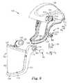
- FIGS. 1-6illustrate a headgear 100 according to one embodiment of the present disclosure.
- the headgear 100includes a headtop 102, a shield 104, and a pivot assembly 106 that allows for relative rotational movement between the headtop 102 and the shield 104.
- the shield 104is pivotally movable with respect to the headtop 102 between an up, or open, position 105, and a down, or closed, position 107.
- the open position 105 illustrated in phantom lines in FIG. 1is shown as an example of one possible open position.
- the shield 104can be removably coupled to the headtop 102.
- the headtop 102is shaped and dimensioned to fit over the top of a user's head to provide cover, means for attaching the shield 104, and/or protection (e.g., impact and/or environmental protection) to a user's head.
- the headtop 102can be formed of a variety of materials, including, but not limited to, at least one of metal (e.g., aluminum, etc.), polymeric materials (e.g., high density polyethylene (HDPE); acrylonitrile-butadienestyrene (ABS); polycarbonate; NYLON polyamide, e.g., from E. I.
- the headtop 102can take on a variety of forms depending on the desired uses.
- the headtop 102can be a simple bump cap, a hard hat, a helmet, and combinations thereof.
- the headgear 100can further include a jaw piece 108 that is coupled to, or forms a portion of, the headtop 102 to provide further cover, additional coupling means for the shield 104, and/or protection to a user's face.
- the jaw piece 108can be rigidly coupled to the headtop 102, and the jaw piece 108 can provide registration and sealing surfaces for various portions of the shield 104.
- the jaw piece 108 and the headtop 102define a first viewing window, or opening, 109 (see FIG. 3 ), such that when the shield 104 moves into its closed position 107, the shield 104 is positioned across the first viewing window 109.
- the headgear 100can further include a strap, or harness, 110 that is coupled to, or forms a portion of, the headtop 102 to provide means for securing the headgear 100 to a user's head.
- the strap 110has been removed from FIG. 3 for clarity.
- the headtop 102is adapted to provide cover to a user's head
- the strap 110is adapted to couple the headgear 100 to the user's head.
- the headtop 102is substantially formed of the strap 110, such that the primary purpose of the headtop 102 is to couple the shield 104 (or other components of the headgear 100) to a user's head, and doesn't necessarily provide cover to the user's head.
- the headgear 100is configured for use in respirator systems, and further includes a port 112 (see FIGS. 1 and 3 ) coupled to the headtop 102 to allow connection to a source of clean (e.g., filtered) air (not shown).
- a source of cleane.g., filtered
- at least a portion of the headgear 100can form an enclosure around the user's face that separates a user's interior gas space from the surrounding exterior gas space.
- a user's breathing zonecan be located between the enclosure and the user's face. Clean air can be provided into the breathing zone from any suitable source of clean air.
- the usercan breathe the air and exhale it back into the breathing zone.
- This exhaled air, along with excess clean air that is moved into the breathing zone,may exit the breathing zone via one or more openings in the enclosure (e.g., around the edges of the shield 104) or through any other suitable route.
- the phrase "clean air”refers to atmospheric ambient air that has been filtered or air supplied from an independent source.
- the phrase "clean air source”refers to an apparatus, such as a filtering unit or a tank that is capable of providing a supply of clean air (or oxygen) for the user of the respirator system.
- the port 112can be coupled to the headtop 102, or can form a portion of the headtop 102, such that the port 112 is in fluid communication with the enclosure of the headgear 100 and a user's nose and/or mouth.
- the port 112can be coupled to an air supply system.
- the air supply systemwhether a positive pressure system or a negative pressure system, can assist in maintaining a net flow of gas out of the enclosure to reduce the chance that contaminants will enter the enclosure.
- the respirator systemcan include, or be coupled to, a clean air supply system (not shown) which can include an inlet configured for connection to a source of clean air and an outlet positioned in fluid communication with the breathing zone.
- a clean air supply system(not shown) which can include an inlet configured for connection to a source of clean air and an outlet positioned in fluid communication with the breathing zone.
- the source of clean aircan be an air exchange apparatus, which can include an apparatus for providing a finite breathing zone volume around the head of a user in which air can be exchanged in conjunction with the user's breathing cycle.
- a respirator system employing an air exchange apparatusis a Powered Air Purifying Respirator" (PAPR), which is a powered system having a blower to force ambient air through air-purifying elements to an inlet of a clean air supply system.
- PAPRPowered Air Purifying Respirator
- the present disclosureis not limited to such systems and may include any other suitable air supply system, including but not limited to negative pressure systems.
- Other exemplary air supply systemsmay include, without limitation, any suitable supplied air system or a compressed air system, such as a self contained breathing apparatus (SCBA).
- SCBAself contained breathing apparatus
- the shield 104includes a frame 120 that is coupled to the headtop 102 via the pivot assembly 106.
- the frame 120can be shaped to provide cover and/or protection to at least a portion of a user's head.
- the shield 104can include a visor that covers a user's eyes, and in some embodiments, as shown in FIGS. 1 and 3 , the shield 104 can include a full face shield.
- the shield 104can be sized and shaped to provide any level of cover or protection desired, depending on the intended use of the headgear 100.
- the shield 104can further include a lens 122 through which the user can see, and a seal 124, which allows the shield 104 to seal against a surface of the headtop 102, and which can be involved in forming an enclosure around a user's face.
- the shield 104can be formed substantially of the lens 122, and the lens 122 can be coupled to the headtop 102 via the pivot assembly 106.
- the shield frame 120can be formed of a variety of materials, including, but not limited to, the materials listed above with respect to the headtop 102.
- the lens 122can be formed of a variety of materials, including, but not limited to, glass, polymeric materials (e.g., polycarbonate, acetate, NYLON® polyamide, acrylic, etc.), other suitable lens materials, and combinations thereof.
- the frame 120 of the shield 104at least partially defines a viewing window, or opening, 123 (e.g., a second viewing window 123 in embodiments that employ a jawpiece 108 that defines a first viewing window 109).
- the lens 122can be removably coupled to the frame 120 across the viewing window 123 to provide additional cover or protection to a user's eyes or face, and to contribute to forming an enclosure around at least a portion of a user's face (e.g., in respiratory applications).
- the frame 120 of the shield 104 shown in FIGS. 1-4is generally U-shaped and includes a lower portion 126 and two upper portions 128 that extend upwardly from the lower portion 126 to be coupled to either side of the headtop 102 via the pivot assembly 106.
- FIG. 2illustrates a close-up bottom view of the left side of the headgear 100 where the left upper portion 128 of the frame 120 of the shield 104 is coupled to the headtop 102 by the pivot assembly 106.
- FIGS. 1illustrates a close-up bottom view of the left side of the headgear 100 where the left upper portion 128 of the frame 120 of the shield 104 is coupled to the headtop 102 by the pivot assembly 106.
- the headtop 102includes a recess 114 on each side that is shaped and dimensioned to receive an upper portion 128 of the shield frame 120, which can create a flush side profile on either side of the headgear 100, while allowing relative rotation between the shield 104 and the headtop 102.
- the shape and overall appearance of the frame 120 of the shield 104 of the illustrated embodimentis shown by way of example only, but it should be understood that other shapes and structures of the shield 104 or shield frame 120 are possible and within the scope of the present disclosure.
- FIGS. 2-6illustrate the pivot assembly 106 in greater detail.
- FIGS. 2-4illustrate how the components of the pivot assembly 106 are coupled to one another, as well as to the headtop 102 and the shield 104.
- FIGS. 5 and 6illustrate the components of the pivot assembly 106 in detail, with the shield 104 removed for clarity.
- the pivot assembly 106includes a housing 130, a socket 132, a post 134, and a spring 136.
- the housing 130can be coupled to the headtop 102 via a variety of removable, semi-permanent, or permanent coupling means, described below.
- the housing 130is integrally formed in the headtop 102, such that the housing 130 is permanently coupled to the headtop 102, and the headtop 102 includes the housing 130 of the pivot assembly 106.
- the housing 130is formed separately from the headtop 102 and removably or semi-permanently coupled to the headtop 102.
- this couplingcan include removable, semi-permanent and permanent types of coupling, and combinations thereof.
- Removable coupling meanscan include, but are not limited to, gravity (e.g., one component can be set atop another component, or a mating portion thereof), screw threads, press-fit engagement (also sometimes referred to as “friction-fit engagement” or “interference-fit engagement”), snap-fit engagement, magnets, hook-and-loop fasteners, adhesives, cohesives, clamps, heat sealing, other suitable removable coupling means, and combinations thereof.
- Permanent or semi-permanent coupling meanscan include, but are not limited to, adhesives, cohesives, stitches, staples, screws, nails, rivets, brads, crimps, welding (e.g., sonic (e.g., ultrasonic) welding), any thermal bonding technique (e.g., heat and/or pressure applied to one or both of the components to be coupled), snap-fit engagement, press-fit engagement, heat sealing, other suitable permanent or semi-permanent coupling means, and combinations thereof.
- weldinge.g., sonic (e.g., ultrasonic) welding
- any thermal bonding techniquee.g., heat and/or pressure applied to one or both of the components to be coupled
- snap-fit engagemente.g., press-fit engagement, heat sealing
- other suitable permanent or semi-permanent coupling meanse.g., heat sealing
- permanent or semi-permanent coupling meanscan also be adapted to be removable, and vice versa, and are categorized in this way by way
- the exemplary housing 130 shown in FIGS. 2-6generally has the shape of a rectangular prism, or cuboid, with the upper two corners being rounded, and includes a front wall 142, a rear wall 144, a bottom wall 145 (see FIGS. 2 and 4 ), and a side wall 146 (see FIGS. 4-6 ) that joins the front and rear walls 142, 144 and forms the sides and top of the housing 130.
- the walls 142, 144, 145, 146 of the housing 130define a hollow interior 138 and an inner surface 148.
- the housing 130further includes a slot, or first aperture, 150 in the bottom wall 145 that provides access to the interior 138 in a first direction D 1 , and a second aperture 152 in the front wall 142 that provides access to the interior 138 in a second direction D 2 , which is different from the first direction (e.g., oriented at an angle with respect to the first direction D 1 ).
- the second direction D 2is oriented substantially perpendicularly with respect to the first direction D 1 .
- the housing 130is oriented with respect to the headtop 102 such that the bottom slot 150 faces downwardly when the headgear 100 is positioned atop a user's head.
- the second aperture 152faces outwardly to the side when the headgear 100 is atop a user's head.
- FIGS. 5 and 6the orientation terms used herein with respect to the pivot assembly 106 will follow the orientation of FIGS. 5 and 6 , with FIG. 5 representing the "front” view and FIG. 6 representing the "rear" view.
- frontrefers to portions of an element that are positioned away from the midline (i.e., toward the side) of the headgear 100, or movement in that direction
- rearrefers to portions of an element that are positioned toward the midline (i.e., toward the center) of the headgear 100, or movement in that direction.
- orientationsuch as “top,” “upper,” “bottom,” and “lower,” are used to refer to elements or movement toward the top of the headgear 100 and the bottom of the headgear 100, respectively.
- the bottom slot 150has a generally rectangular cross-sectional shape
- the second aperture 152has a generally circular cross-sectional shape.
- the first and second apertures 150 and 152are shaped to accommodate other components of the pivot assembly 106 and to encourage relative rotation about a central axis A (see FIGS. 4-6 ); however, it should be understood that other shapes are possible, as long as the aperture shapes provide adequate coupling and cooperation with the other components of the pivot assembly 106.
- the socket 132is shaped and dimensioned to be received in the interior 138 of the housing 130. Particularly, the socket 132 is configured to be slid in the first direction D 1 into the housing 130 via the bottom slot 150.
- the socket 132can be coupled to the housing 130 via any of the above-described coupling means. That is, the socket 132 can include a variety of coupling or orienting features and/or textures to encourage proper and facile positioning of the socket 132 within the housing 130.
- the socket 132 of the illustrated embodimentincludes a slot, or aperture, 154 formed through the socket 132 near a side wall of the socket 132, forming a resilient member such as a flexible and thin wall 155 in the side of the socket 132.
- the resilient memberhere, the thin wall 155, can flex inwardly as the socket 132 is slid into the housing 130 to allow a tighter interference fit between at least a portion of an outer surface 156 of the socket 132 and the inner surface 148 of the housing 130, and to inhibit relative movement between the socket 132 and the housing 130.
- the thin wall 155is only one example of a resilient member that can be employed to facilitate coupling the socket 132 to the housing 130 and to inhibit relative movement between the socket 132 and the housing 130, but that other suitable resilient and/or movable members can be employed to accomplish such functions.
- other resilient memberscan include, but are not limited to, a resilient or elastomeric material positioned on at least one of the outer surface 156 of the socket 132 and the inner surface 148 of the housing 130; one or more cam surfaces positioned on at least one of the outer surface 156 of the socket 132 and the inner surface 148 of the housing 130; other suitable resilient or movable members; and combinations thereof.
- the thin wall 155can further include an outwardly-projecting protrusion 158 that can cam along the inner surface 148 of the housing 130 as the socket 132 is moved into the interior 138 of the housing 130, and which can provide an interference fit between the socket 132 and the inner surface 148 of the housing 130.
- an outwardly-projecting protrusion 158can cam along the inner surface 148 of the housing 130 as the socket 132 is moved into the interior 138 of the housing 130, and which can provide an interference fit between the socket 132 and the inner surface 148 of the housing 130.
- the housingcan include a correspondingly-shaped recess 159 formed in the side wall 146 of the housing 130 that is dimensioned to receive the protrusion 158, such that the protrusion 158 can move into engagement (e.g., snap) with the recess 159 of the housing 130 as the socket 132 is slid into the housing 130.
- Such coupling and orientation features between the socket 132 and the housing 130can enhance the engagement between the socket 132 and the housing 130, and can further function as orientation guides to allow facile assembly in one orientation.
- some embodiments of the pivot assembly 106do not include such coupling and orientation features between the socket 132 and the housing 130.
- the socket 132can further include at least one socket locating feature, such as a rearwardly-projecting protrusion 160 that is shaped and dimensioned to engage or mate with at least one corresponding housing locating feature, such as a recess 162 formed in the inner surface 148 of the rear wall 144 of the housing 130.
- the engagement of the protrusion 160 of the socket 132 and the recess 162 of the housing 130can serve to stabilize the socket 132 with respect to the housing 130 in a desired spatial arrangement and can inhibit removal of the socket 132 from the housing 130.
- the protrusion 160 and recess 162are shown by way of example only, but one of ordinary skill in the art should understand that the protrusion 160 can instead be located on the housing 130 and the recess 162 can be located on the socket 132, a plurality of such features can be included, and/or a variety of other shapes and sizes of locating features could be used to encourage coupling of the socket 132 and the housing 130.
- the socket 132includes a front surface 164 and one or more engagement features 166 that form at least a portion of the front surface 164, and which are configured to engage the post 134, as will be described in greater detail below.
- engagement featureis used to generally refer to a protrusion or recess that is shaped to cooperate with one or more similarly shaped and sized recesses or protrusions, respectively, to provide coupling between two components.
- the engagement features 166include five equally-spaced, recesses that are arranged in a windmill pattern (i.e., circumferentially) about a center point C, each recess having generally a frusto-sector shape and having arcuate top and bottom surfaces.
- the socket 132can further include a coupling or orientation feature, such as a shaft 168 that is centered about the same center point C as the engagement features 166, and which extends outwardly from the front surface 164 of the socket 132 to further engage the post 134, as will be described in greater detail below.
- a coupling or orientation featuresuch as a shaft 168 that is centered about the same center point C as the engagement features 166, and which extends outwardly from the front surface 164 of the socket 132 to further engage the post 134, as will be described in greater detail below.
- the second aperture 152 of the housing 130is concentric with the engagement features 166 and the shaft 168.
- the engagement features 166 and the shaft 168 of the socket 132are positioned co-axially with respect to the second aperture 152 of the housing 130 about the axis A, which forms the rotational axis of the pivot assembly 106.
- such an arrangementis shown by way of example only, and that some embodiments do not include such concentricity between the second aperture 152 of the housing 130 and the socket 132.
- the post 134 of the pivot assembly 106includes a front (or an outer) portion 170 that couples to the shield 104, and a rear (or an inner) portion 172 that couples to the socket 132.
- the post 134can be coupled to the shield 104 via a variety of removable, semi-permanent, or permanent coupling means, such as those described above.
- the post 134is removably coupled to the shield 104.
- this embodimentis shown and described by way of example only, and it should be understood that in some embodiments, the post 134 can be semi-permanently or permanently coupled to the shield 104.
- the post 134(e.g., the front portion 170 of the post 134) can be integrally formed with the shield 104, such that the shield 104 includes the post 134.
- this couplingcan include removable, semi-permanent and permanent types of coupling, and combinations thereof.
- the front portion 170is joined with the rear portion 172 by a generally cylindrical shaft 174 that is configured to rotate about the axis A when the pivot assembly 106 is assembled.
- the shaft 174includes a bore 175 that is dimensioned to receive the shaft 168 of the socket 132 to further enhance the coupling and cooperation between the post 134 and the socket 132.
- the post 134can include the shaft 168 and the socket 132 can include the bore 175. It should be further understood that, in some embodiments, such additional means of coupling and aligning the post 134 and the socket 132 are not present at all.
- the front portion 170 of the post 134includes a first flange 176 that extends laterally outwardly from the shaft 174 and which is shaped and dimensioned to be received in a pocket 178 formed in the frame 120 of the shield 104 (see FIGS. 2-4 ).
- the flange 176has a generally rectangular shape with rounded corners, and forms the portion of the pivot assembly 106 that can be seen when the assembled headgear 100 is viewed from the side.
- the generally rectangular shape of the flange 176allows the flange 176 to be coupled to the shield 104 for rotation therewith, such that when the shield 104 is rotated relative to the headtop 102, the flange 176 is inhibited from rotating relative to the shield 104.
- the flange 176can take on a variety of other suitable shapes.
- the rear-facing surface of the flange 176can include a rib 177 that extends laterally outwardly from the shaft 174, and which has its length oriented laterally.
- the rib 177provides an orientation feature on the post 134 that is shaped and dimensioned to be received in a correspondingly shaped recess 179 (see FIG. 3 ) of the pocket 178 of the shield frame 120.
- the rib 177is positioned in the upper vertical half of the flange 176. Such positioning of the rib 177, in combination with the rectangular shape of the flange 176 ensures that the post 134 will only fit in the pocket 178 of the shield frame 120 one way.
- Such shaping of elements and orientation featuresallow for facile assembly of the pivot assembly 106.
- pivot assembly 106do not include any such rib or other orientation feature between the post 134 and the shield frame 120.
- the outer surface of the flange 176is smooth and flat, such that the pivot assembly 106 is flush or recessed with respect to the outer surface of the headgear 100.
- the post 134further includes a second annular flange 180 (see FIGS. 4 and 6 ) spaced a short distance behind the flange 176 that extends radially outwardly from the shaft 174.
- the annular flange 180has a chamfered outer diameter that tapers rearwardly (i.e., in the direction opposite the flange 176).
- the annular flange 180is shaped and sized to fit through an aperture 182 (see FIG. 3 ) formed in the rear of the pocket 178 of the shield frame 120.
- the rear portion of the annular flange 180is similar in size or smaller than the inner diameter of the aperture 182 of the shield frame 120 to allow the rear portion of the annular flange 180 to easily fit through the aperture 182, and the front portion of the annular flange 180 is slightly larger than the inner diameter of the aperture 182, such that the post 134 is at least somewhat inhibited from being removed from the shield frame 120.
- the forward end of the annular flange 180(i.e., the portion forming the largest outer diameter of the annular flange 180) is rounded to allow the post 134 to be removed from the shield frame 120 when sufficient force is applied to allow for an annular snap-fit-type engagement between the annular flange 180 of the post 134 and the rear aperture 182 of the shield frame 120.
- the post 134can be secured to the shield 104, for example, by securing the pivot assembly 106 in an assembled state.
- the rear portion 172 of the post 134includes a rear surface 184 and one or more engagement features 186 that form at least a portion of the rear surface 184, and which are configured to engage the engagement features 166 of the socket 132.
- the post 134includes five equally-spaced, protrusions that are arranged circumferentially about the shaft 174.
- each protrusionhas a generally frusto-sector shape, with arcuate top and bottom surfaces, and is shaped and dimensioned to be received in the recessed engagement features 166 of the socket 132.
- One of the socket engagement features 166 and the post engagement features 186can be larger than the other to allow the socket 132 and the post 134 to rotate relative to one another without substantial friction or difficulty.
- the socket engagement features 166are larger than the post engagement features 186 in diameter and depth but the same in other dimensions to allow facile relative rotational movement, while maintaining integrity in the detent positions provided by the engagement of the socket engagement features 166 and the post engagement features 186.
- the socket engagement features 166 of the illustrated embodimentare described herein as “recesses,” and the post engagement features 186 are described as “protrusions” that are received in the recessed socket engagement features 166.
- the raised areas on the socket 132 between the recessescan instead be referred to as the socket engagement features 166, such that the illustrated socket engagement features 166 are referred to as “protrusions.”
- the recessed areas between the protrusions on the rear portion 172 of the post 134can instead be referred to as the post engagement features 186, such that the illustrated post engagement features 186 are referred to as "recesses.”
- the terms “protrusions” and “recesses”are used by way of example only to describe the relative engagement between the socket 132 and the post 134, and are not intended to be limiting.
- one or both of the socket engagement features 166 and the post engagement features 186can include chamfered surfaces to allow the engagement features 166, 186 to cam into and out of engagement with one another as the socket 132 and post 134 are rotated with respect to one another.
- each of the radially-extending walls of the socket engagement features 166 and the post engagement features 186is chamfered to allow the socket 132 and the post 134 to rotate with respect to one another without undue force.
- the pivot assembly 106can include a longitudinal axis B that runs through the center of the pivot assembly 106.
- the socket engagement features 166 and the post engagement features 186can be arranged such that the socket engagement features 166 and the post engagement features 186 each have mirror symmetry over the longitudinal axis B.
- the spring 136has mirror symmetry over the longitudinal axis B. Such mirror, or axial, symmetry can allow for common parts. That is, the same socket 132, post 134, and spring 136 (and pivot assembly 106) can be used on either the left side or the right side of the headgear 100.
- one or both of the socket engagement features 166 and the post engagement features 186can include one or more lines of rotational symmetry.
- the illustrated socket engagement features 166are rotationally symmetric about the axis A of rotation
- the illustrated post engagement features 186are rotationally symmetric about the axis A.
- the socket engagement features 166 and the post engagement features 186are shown by way of example only, but it should be understood that a variety of different engagement features can be employed without departing from the spirit and scope of the present invention.
- a different number of engagement features 166, 186can be used, the number of socket engagement features 166 does not have to equal the number of post engagement features 186, other shapes of engagement features can be employed, the engagement features can include more or fewer lines of symmetry, other relative sizes can be employed (e.g., the relative size between one socket engagement feature 166 and one post engagement feature 186), and other detent and cam features can be employed to accomplish the metered, relative rotational movement.
- the post 134is dimensioned to be received in the second aperture 152 of the housing 130 to access the socket 132. That is, the post 134 can be coupled to the housing 130 by moving at least a portion of the post 134 into the second aperture 152 along the second direction D 2 . The post 134 can be secured to the socket 132 and the housing 130 with the spring 136, which is described in greater detail below.
- the socket 132 and the post 134can be formed of a variety of materials that provide the desired level of rigidity and dimensional stability to ensure proper cooperation and engagement between the socket 132 and the post 134.
- the socket 132 and the post 134can be formed of the same or different materials.
- suitable socket and/or post materialscan include, but are not limited to, at least one of metal (e.g., stainless steel, zinc, aluminum, etc.), polymeric materials (e.g., acetal, polypropylene, polyethylene, etc.), and combinations thereof.
- the spring 136is shaped and dimensioned to be received in the interior 138 of the housing 130 via the bottom slot 150 in the housing 130, for example, by moving the spring 136 into the housing 130 along the first direction D 1 .
- the spring 136shown in the embodiment illustrated in FIGS. 1-6 by way of example only, is a leaf spring that is generally U-shaped, such that the spring 136 includes a base 185, two prongs 187 that extend upwardly from the base 185, two inner edges 188 and two outer edges 189.
- the inner edges 188form the inner curve of the "U" and are dimensioned to receive and abut the cylindrical shaft 174 of the post 134.
- the outer edges 189can be substantially straight and parallel to the side wall 146 of the housing when the spring 136 is positioned within the housing 130. In the illustrated embodiment, when the spring 136 is inserted into the housing 130, the two prongs 187 of the spring 136 each move along either side of the shaft 174 of the post 134.
- the rear portion 172 of the post 134 that is dimensioned to be received in the second aperture 152 to engage the socket 132further includes a rear annular flange 190 that extends radially outwardly from the shaft 174.
- the rear portion of the annular flange 190forms the rear surface 184 of the post 134.
- the prongs 187 of the spring 136are spaced a distance apart that is less than the outer diameter of the rear annular flange 190, such that the prongs 187 engage the rear annular flange 190 of the post 134.
- the prongs 187 of the spring 136can include a curved cross-sectional shape (see FIG.
- the curved cross-sectional shapeis shown in the illustrated embodiment by way of example only, but other suitable cross-sectional shapes can be employed to provide the biasing force.
- the biasing forceholds the rear portion 172 of the post 134 in the housing 130 and biases the post engagement features 186 into engagement with the socket engagement features 166.
- the spring 136can further include a desired amount of flex to allow the post 134 to rotate with respect to the socket 132, and to allow the post engagement features 186 to move into and out of engagement with the socket engagement features 166 as the post 134 and socket 132 are rotated with respect to one another.
- the spring 136stores the force necessary to provide a desired amount of resistance for moving the shield 104 with respect to the headtop 102 between the open and closed positions 105, 107, such that the shield 104 can be maintained in either the open position 105, the closed position 107, or intermediately thereof, as desired.
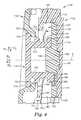
- the base 185 of the spring 136can include a first tab 192 that is oriented at an angle (e.g., about 90 degrees, see FIG. 4 ) with respect to the main body 194 of the base 185, and which is dimensioned to fit over the portion of the front wall 142 of the housing 130 that forms the bottom slot 150. Additionally or alternatively, the spring 136 can include a second tab 196 that is positioned intermediately of the two prongs 187. The second tab 196 is oriented at an angle (e.g., about 90 degrees, see FIG. 4 ) with respect to the main body 194 of the base 185, and is dimensioned to fit over a bottom portion of the second aperture 152 of the housing 130 (see FIGS. 4 and 5 ).
- the stored force in the spring 136can further bias the base 185 of the spring 136 toward the front wall 142 of the housing 130 generally in a fourth direction D 4 to bias the first and/or second tabs 192, 196 into engagement with the housing 130.
- the fourth direction D 4is oriented substantially opposite the second direction D 2 .
- the spring 136can be configured to have the additional function of locking the pivot assembly 106 in an assembled state (see FIGS. 2 and 4 ), and the base 185 of the spring 136 can function as a disassembly feature for the pivot assembly 106.
- the base 185 of the spring 136can be pressed rearwardly toward the headtop 102 (i.e., substantially in the second direction D 2 , toward the right-hand side of FIG. 4 ) to release the first and second tabs 192 and 196 from engagement with the housing 130.
- the spring 136can be pulled downwardly out of the housing 130 in a third direction D 3 , which is oriented substantially opposite the first direction D 1 , to remove the spring 136 from the housing 130.
- the spring 136engages with the housing 130 and the post 134 to provide the necessary biasing force for maintaining: (i) the socket 132 toward the rear wall 144 of the housing 130, (ii) the protrusion 160 of the socket 132 into engagement with the recess 162 on the rear wall of the housing 130, (iii) the post engagement features 186 into engagement with the socket engagement features 166, and (iv) the base 185 of the spring 136 into engagement with the housing 130 to inhibit (i) the socket 132 from being removed from the housing 130 via the bottom slot 150, (ii) the post 134 from being removed from housing 130 via the second aperture 152, and (iii) the spring 136 from being removed from the housing 130 until sufficient disassembly force is applied to the base 185 of the spring 136, all while allowing the post 134 (i.e., the shield 104) and the socket 132 (i.e., the headtop 102) to be rotated relative to one another when
- the spring 136therefore functions to bias the post 134 and the socket 132 together, and can also function to lock the pivot assembly 106 in an assembled state.
- the pivot assembly 106is adapted for facile assembly and disassembly, and does not require the use of any external tools.
- each of the components of the illustrated pivot assembly 106is common to the left or right side of the headgear 100, such that parts can be replaced individually.
- some embodiments of the pivot assembly 106provide one or more orientation features between adjoining components, such that the components can be assembled in only one orientation.
- the spring 136can consistently provide the sufficient biasing and holding forces to allow the necessary relative rotation between the shield 104 and the headtop 102, without requiring adjustments to maintain the pivot assembly 106 in an assembled state.
- the spring 136can be formed of a variety of materials that have dimensional stability, and which have, or can be adapted to have, the necessary spring constant.
- suitable spring materialscan include, but are not limited to, at least one of metal (e.g., carbon steel, stainless steel, clock spring steel, beryllium-copper, etc.), polymeric materials (e.g., acetal, polycarbonate, etc.), elastomeric materials (e.g., urethanes, synthetic or natural rubbers, etc.), and combinations thereof.
- the headgear 100can be assembled by coupling the upper portions 128 of the shield frame 120 to the recesses 114 in the headtop 102 with the pivot assembly 106.
- the headgear 100can be assembled by coupling the upper portions 128 of the shield frame 120 to the recesses 114 in the headtop 102 with the pivot assembly 106.
- the same descriptioncan be applied to both sides of the headgear 100, and that both sides can be coupled simultaneously or sequentially.
- the following exemplary coupling and decoupling procedureswill be described with respect to one illustrated embodiment; however, it should be understood that some steps may not be necessary for all embodiments of the present disclosure.
- the socket 132can be moved along the first direction D 1 into the interior 138 of the housing 130.
- the outwardly-projecting protrusion 158cams along the inner surface 148 of the housing 130, and the thin wall 155 is flexed until the protrusion 158 snaps into engagement with the recess 159 in the side wall 146 of the housing 130 (or, in the case of no recess 159, until the socket 132 forms an interference fit with the inner surface 148 of the housing 130).
- the rearwardly-projecting protrusion 160 of the socket 132is positioned within the recess 162 on the rear wall 144 of the housing 130 as the socket 132 is positioned within the housing 130.
- the post 134can be coupled to the upper portion 128 of the shield frame 120 by being moved in the second direction D 2 until the flange 176 and orientation rib 177 are received in the pocket 178 of the shield frame 120 and the rear portion 172 of the post 134 is received through the rear aperture 182 at the back of the pocket 178.
- the rear portion 172 of the post 134can then be coupled to the socket 132 by moving the upper portion 128 of the shield frame 120 and the post 134 generally along the second direction D 2 until the rear portion 172 of the post 134 is received through the second aperture 152 of the housing 130 and the post engagement features 186 are positioned at least partially in engagement with the socket engagement features 166.
- the post 134can first be coupled to the shield frame 120, and then the post 134 and the shield frame 120 can be coupled to the housing 130.
- the upper portion 128 of the shield frame 120can first be positioned in the recess 114 of the headtop 102, and then the post 134 can be coupled to the shield frame 120 and the housing 130 simultaneously.
- the spring 136can then be moved in the first direction D 1 into the bottom slot 150 of the housing 130, and the two prongs 187 can be slid along the cylindrical shaft 174 of the post 134 to engage the rear annular flange 190 of the post 134.
- the spring 136can be moved in the first direction D 1 until the spring 136 abuts the cylindrical shaft 174 of the post 134 and/or the first and second tabs 192, 196 of the spring 136 engage the front wall 142 of the housing 130.
- the shield 104can then be rotated relative to the headtop 102 by overcoming the resistance of the spring 136 to move the post engagement features 186 out of engagement with the socket engagement features 166.
- the shield 104can be removed from the headtop 102 by disassembling the pivot assembly 106, and decoupling the upper portion 128 of the shield frame 120 from the recesses 114 in the headtop 102, which can occur simultaneously or sequentially.
- the base 185 of the spring 136can be pressed rearwardly (i.e., toward the rear wall 144 of the housing 130, generally in the second direction D 2 ) and downwardly in the third direction D 3 to remove the spring 136 from the interior 138 of the housing 130.
- the prongs 187are slid out of engagement with the rear annular flange 190 of the post 134, and the post 134 is no longer biased into contact with the socket 132.
- the post 134can be removed by moving the post 134 out of the second aperture 152 of the housing 130 along the fourth direction D 4 , which is substantially opposite the second direction D 2 .
- the post 134can also be removed from the pocket 178 of the shield frame 120, allowing the shield frame 120 to be decoupled from the headtop 102.
- the shield frame 120 and post 134can be decoupled from headtop 102 together, and the post 134 can then be removed from the shield frame 120.
- the socket 132can be removed from the interior 138 of the housing 130 by moving the socket 132 in the third direction out of the bottom slot 150 of the housing 130.
- the outwardly-projecting protrusion 158can be decoupled from the recess 159 in the side wall 146 of the housing 130, and the rearward protrusion 160 of the socket 132 can be decoupled from the recess 162 in the rear wall 144 of the housing 130.
Landscapes
- Helmets And Other Head Coverings (AREA)
Description
- The present disclosure generally relates to a pivot assembly for use with headgear, and particularly, for use with headgear having a headtop portion and an eye- or face-covering portion that is movable relative to the headtop portion.
- Headgear is used in a variety of applications to provide covering and/or protection to a user's head. Some headgear includes a visor or a faceshield that is pivotally movable with respect to a headtop between an open and closed position. Such headgear may further include one or more components that function as a pivot mechanism to attempt to control the movement of the visor or faceshield between the open and closed positions. Such controlled movement can allow the visor or faceshield to be maintained in the open or closed position, or in a position intermediate of the open and closed positions. Some pivot mechanisms include detent-type hinge mechanisms, threaded engagements, or mechanisms that require the use of external tools for assembly or disassembly. In addition, some pivot mechanisms include components that can be coupled together in a variety of ways, and components that are unique to either the left side or the right side of the headgear. Furthermore, some pivot mechanisms require additional locking means in order to maintain the visor or faceshield in a desired position.
US 6,298,498 B1 discloses a protective helmet system wherein a jaw piece is attachable to a base edge of the helmet. The jaw piece and a portion of the base edge of the helmet define a user viewing window. A first face shield is pivotable between an open position and a closed position extending across the viewing window. A seal is provided to engage with a perimeter of the viewing window when the first face shield is in the closed position. The attaching assembly for attaching the first face shield comprises a helmet cam having first helmet cam surfaces configured to releasably attach the first face shield to the protective helmet system and second helmet cam surfaces configured to releasably attach a second face shield to the protective helmet. The attaching assembly generates a first biasing force to bias the seal toward the perimeter of the viewing window when the first face shield is in the closed position.- The pivot assembly for a headgear and the method for coupling a shield of a headgear to a head top of the headgear according to the present invention are defined by the features of the claims.
- Some embodiments of the present disclosure provide a pivot assembly for headgear comprising a headtop and a shield. The pivot assembly can include a housing adapted to be coupled to the headtop, the housing having an interior. The pivot assembly can further include a socket dimensioned to be received in the interior of the housing, the socket including a plurality of first engagement features, and a post adapted to be coupled to the shield, the post including a plurality of second engagement features adapted to engage the plurality of first engagement features. At least a portion of the post can be dimensioned to be received in the interior of the housing. The pivot assembly can further include a spring dimensioned to be received in the interior of the housing to engage the post and to bias the plurality of second engagement features into engagement with the plurality of first engagement features while allowing relative rotation between the post and the socket.
- Some embodiments of the present disclosure provide a pivot assembly for headgear that comprises a headtop and a shield. The pivot assembly can include a housing adapted to be coupled to the headtop. The housing can include an interior, a first aperture positioned to provide access to the interior along a first direction, and a second aperture positioned to provide access to the interior of the housing along a second direction, the second direction being oriented at an angle with respect to the first direction. The pivot assembly can further include a socket dimensioned to be received in the interior of the housing via the first aperture, the socket including a plurality of first engagement features, and a post adapted to be coupled to the shield, the post including a plurality of second engagement features adapted to engage the plurality of first engagement features. At least one of the plurality of first engagement features and the plurality of second engagement features can include at least one cam surface configured to allow relative rotational movement between the socket and the post. At least a portion of the post can be dimensioned to be received in the interior of the housing via the second aperture. The pivot assembly can further include a spring dimensioned to be received in the interior via the first aperture of the housing to engage the post. The spring can be configured to provide a biasing force substantially along the second direction to bias the second plurality of engagement features into engagement with the first plurality of engagement features while allowing relative rotation between the post and the socket.
- Some embodiments of the present disclosure provide a headgear comprising a headtop, a shield, and a pivot assembly adapted to couple the headtop and the shield, such that the shield is pivotally movable relative to the headtop between an open position and a closed position. The pivot assembly can include a housing coupled to the headtop. The housing can include an interior, a first aperture positioned to provide access to the interior along a first direction, and a second aperture positioned to provide access to the interior of the housing along a second direction, the second direction being different from the first direction. The pivot assembly can further include a socket dimensioned to be received within the interior of the housing via the first aperture of the housing, the socket having a plurality of first engagement features, and a post coupled to the shield, the post having a plurality of second engagement features adapted to engage the plurality of first engagement features of the socket. At least a portion of the post can be dimensioned to be received in the interior of the housing via the second aperture of the housing. The pivot assembly can further include a spring dimensioned to be received within the interior of the housing via the first aperture of the housing. The spring can be adapted to: (i) engage the post, (ii) bias the plurality of second engagement features into engagement with the plurality of first engagement features, and (iii) engage the housing to reversibly lock the pivot assembly in an assembled state.
- Some embodiments of the present disclosure provide a method for coupling a shield of a headgear to a headtop of the headgear to allow relative rotation between the shield and the headtop. The method can include providing a housing comprising an interior. The housing can be coupled to the headtop of the headgear. The method can further include moving a socket in a first direction into the interior of the housing. The socket can include a plurality of first engagement features. The method can further include providing a post having a plurality of second engagement features adapted to engage the plurality of first engagement features. The post can be coupled to the shield of the headgear. The method can further include moving the post in a second direction toward engagement with the socket, the second direction being different from the first direction. The method can further include moving a spring in the first direction into the interior of the housing and into engagement with at least a portion of the post. The spring can be adapted to bias the plurality of first engagement features and the plurality of second engagement features into engagement while allowing relative rotational movement between the post and the socket.
- Other features and aspects of the present disclosure will become apparent by consideration of the detailed description and accompanying drawings.
FIG. 1 is a perspective view of a headgear according to one embodiment of the present disclosure, the headgear including a headtop, a shield, and two pivot assemblies (one pivot assembly shown).FIG. 2 is a bottom perspective view of the headgear ofFIG. 1 .FIG. 3 is a top exploded perspective view of the headgear ofFIGS. 1 and 2 , with only one pivot assembly shown for clarity.FIG. 4 is a side cross-sectional view of the headgear ofFIGS. 1-3 , taken along line 4-4 ofFIG. 1 .FIG. 5 is a front close-up exploded perspective view of the headtop and pivot assembly ofFIGS. 1-4 .FIG. 6 is a rear close-up exploded perspective view of the headtop and pivot assembly ofFIGS. 1-5 .- Before any embodiments of the invention are explained in detail, it is to be understood that the invention is not limited in its application to the details of construction and the arrangement of components set forth in the following description or illustrated in the following drawings. The invention is capable of other embodiments and of being practiced or of being carried out in various ways. Also, it is to be understood that the phraseology and terminology used herein is for the purpose of description and should not be regarded as limiting. The use of "including," "comprising," or "having" and variations thereof herein is meant to encompass the items listed thereafter and equivalents thereof as well as additional items. Unless specified or limited otherwise, the terms "connected," "supported," and "coupled" and variations thereof are used broadly and encompass both direct and indirect connections, supports, and couplings. Further, "connected" and "coupled" are not restricted to physical or mechanical connections or couplings. It is to be understood that other embodiments may be utilized, and structural or logical changes may be made without departing from the scope of the present disclosure. Furthermore, terms such as "front," "rear," "top," "bottom," and the like are only used to describe elements as they relate to one another, but are in no way meant to recite specific orientations of the apparatus, to indicate or imply necessary or required orientations of the apparatus, or to specify how the invention described herein will be used, mounted, displayed, or positioned in use.
- The present disclosure generally relates to a pivot assembly for use with headgear, and particularly, for use with headgear having a headtop portion and an eye- or face-covering portion (e.g., a shield) that is movable relative to the headtop portion. The pivot assembly of the present disclosure provides a slim, low-profile, easy-to-install apparatus for coupling the headtop portion to the eye- or face-covering portion, while still allowing relative movement between the headtop portion and the eye- or face-covering portion.
FIGS. 1-6 illustrate aheadgear 100 according to one embodiment of the present disclosure. As shown inFIG. 1 , theheadgear 100 includes aheadtop 102, ashield 104, and apivot assembly 106 that allows for relative rotational movement between theheadtop 102 and theshield 104. As further shown inFIG. 1 , theshield 104 is pivotally movable with respect to theheadtop 102 between an up, or open,position 105, and a down, or closed,position 107. Theopen position 105 illustrated in phantom lines inFIG. 1 is shown as an example of one possible open position. However, it should be understood that a variety of other positions beyond the illustratedopen position 105 and intermediate of the illustratedopen position 105 and theclosed position 107 are possible and within the scope of the present disclosure. Theshield 104 can be removably coupled to theheadtop 102.- The
headtop 102 is shaped and dimensioned to fit over the top of a user's head to provide cover, means for attaching theshield 104, and/or protection (e.g., impact and/or environmental protection) to a user's head. Theheadtop 102 can be formed of a variety of materials, including, but not limited to, at least one of metal (e.g., aluminum, etc.), polymeric materials (e.g., high density polyethylene (HDPE); acrylonitrile-butadienestyrene (ABS); polycarbonate; NYLON polyamide, e.g., from E. I. du Pont de Nemours and Company, Wilmington, DE; etc.), composite materials (e.g., fiber reinforced NYLON polyamide, fiber reinforced polyester), other suitable materials, and combinations thereof. In addition, theheadtop 102 can take on a variety of forms depending on the desired uses. For example, in some embodiments, theheadtop 102 can be a simple bump cap, a hard hat, a helmet, and combinations thereof. - In some embodiments, as shown in
FIGS. 1 and3 , theheadgear 100 can further include ajaw piece 108 that is coupled to, or forms a portion of, theheadtop 102 to provide further cover, additional coupling means for theshield 104, and/or protection to a user's face. In embodiments employing thejaw piece 108, thejaw piece 108 can be rigidly coupled to theheadtop 102, and thejaw piece 108 can provide registration and sealing surfaces for various portions of theshield 104. In embodiments employing ajaw piece 108, thejaw piece 108 and theheadtop 102 define a first viewing window, or opening, 109 (seeFIG. 3 ), such that when theshield 104 moves into itsclosed position 107, theshield 104 is positioned across thefirst viewing window 109. - In some embodiments, the
headgear 100 can further include a strap, or harness, 110 that is coupled to, or forms a portion of, theheadtop 102 to provide means for securing theheadgear 100 to a user's head. Thestrap 110 has been removed fromFIG. 3 for clarity. - In the illustrated embodiment, the
headtop 102 is adapted to provide cover to a user's head, and thestrap 110 is adapted to couple theheadgear 100 to the user's head. However, in some embodiments, theheadtop 102 is substantially formed of thestrap 110, such that the primary purpose of theheadtop 102 is to couple the shield 104 (or other components of the headgear 100) to a user's head, and doesn't necessarily provide cover to the user's head. - In some embodiments, as shown in
FIG. 1 , theheadgear 100 is configured for use in respirator systems, and further includes a port 112 (seeFIGS. 1 and3 ) coupled to theheadtop 102 to allow connection to a source of clean (e.g., filtered) air (not shown). In such embodiments, at least a portion of the headgear 100 (e.g., theheadtop 102, theshield 104 and thejaw piece 108, if employed) can form an enclosure around the user's face that separates a user's interior gas space from the surrounding exterior gas space. A user's breathing zone can be located between the enclosure and the user's face. Clean air can be provided into the breathing zone from any suitable source of clean air. The user can breathe the air and exhale it back into the breathing zone. This exhaled air, along with excess clean air that is moved into the breathing zone, may exit the breathing zone via one or more openings in the enclosure (e.g., around the edges of the shield 104) or through any other suitable route. For the purposes of the present disclosure, the phrase "clean air" refers to atmospheric ambient air that has been filtered or air supplied from an independent source. The phrase "clean air source" refers to an apparatus, such as a filtering unit or a tank that is capable of providing a supply of clean air (or oxygen) for the user of the respirator system. - The
port 112 can be coupled to theheadtop 102, or can form a portion of theheadtop 102, such that theport 112 is in fluid communication with the enclosure of theheadgear 100 and a user's nose and/or mouth. Theport 112 can be coupled to an air supply system. The air supply system, whether a positive pressure system or a negative pressure system, can assist in maintaining a net flow of gas out of the enclosure to reduce the chance that contaminants will enter the enclosure. - In embodiments in which the
headgear 100 is configured for use in a respirator system, the respirator system can include, or be coupled to, a clean air supply system (not shown) which can include an inlet configured for connection to a source of clean air and an outlet positioned in fluid communication with the breathing zone. In some embodiments, the source of clean air can be an air exchange apparatus, which can include an apparatus for providing a finite breathing zone volume around the head of a user in which air can be exchanged in conjunction with the user's breathing cycle. - One example of a respirator system employing an air exchange apparatus is a Powered Air Purifying Respirator" (PAPR), which is a powered system having a blower to force ambient air through air-purifying elements to an inlet of a clean air supply system. However, the present disclosure is not limited to such systems and may include any other suitable air supply system, including but not limited to negative pressure systems. Other exemplary air supply systems may include, without limitation, any suitable supplied air system or a compressed air system, such as a self contained breathing apparatus (SCBA).
- In the illustrated embodiment, the
shield 104 includes aframe 120 that is coupled to theheadtop 102 via thepivot assembly 106. Theframe 120 can be shaped to provide cover and/or protection to at least a portion of a user's head. For example, in some embodiments, theshield 104 can include a visor that covers a user's eyes, and in some embodiments, as shown inFIGS. 1 and3 , theshield 104 can include a full face shield. Theshield 104 can be sized and shaped to provide any level of cover or protection desired, depending on the intended use of theheadgear 100. Theshield 104 can further include alens 122 through which the user can see, and aseal 124, which allows theshield 104 to seal against a surface of theheadtop 102, and which can be involved in forming an enclosure around a user's face. In some embodiments, theshield 104 can be formed substantially of thelens 122, and thelens 122 can be coupled to theheadtop 102 via thepivot assembly 106. - The
shield frame 120 can be formed of a variety of materials, including, but not limited to, the materials listed above with respect to theheadtop 102. Thelens 122 can be formed of a variety of materials, including, but not limited to, glass, polymeric materials (e.g., polycarbonate, acetate, NYLON® polyamide, acrylic, etc.), other suitable lens materials, and combinations thereof. - The
frame 120 of theshield 104 at least partially defines a viewing window, or opening, 123 (e.g., asecond viewing window 123 in embodiments that employ ajawpiece 108 that defines a first viewing window 109). Thelens 122 can be removably coupled to theframe 120 across theviewing window 123 to provide additional cover or protection to a user's eyes or face, and to contribute to forming an enclosure around at least a portion of a user's face (e.g., in respiratory applications). - The
frame 120 of theshield 104 shown inFIGS. 1-4 is generally U-shaped and includes alower portion 126 and twoupper portions 128 that extend upwardly from thelower portion 126 to be coupled to either side of theheadtop 102 via thepivot assembly 106.FIG. 2 illustrates a close-up bottom view of the left side of theheadgear 100 where the leftupper portion 128 of theframe 120 of theshield 104 is coupled to theheadtop 102 by thepivot assembly 106. In some embodiments, as shown inFIGS. 1-3 , theheadtop 102 includes arecess 114 on each side that is shaped and dimensioned to receive anupper portion 128 of theshield frame 120, which can create a flush side profile on either side of theheadgear 100, while allowing relative rotation between theshield 104 and theheadtop 102. The shape and overall appearance of theframe 120 of theshield 104 of the illustrated embodiment is shown by way of example only, but it should be understood that other shapes and structures of theshield 104 orshield frame 120 are possible and within the scope of the present disclosure. FIGS. 2-6 illustrate thepivot assembly 106 in greater detail.FIGS. 2-4 illustrate how the components of thepivot assembly 106 are coupled to one another, as well as to theheadtop 102 and theshield 104.FIGS. 5 and6 illustrate the components of thepivot assembly 106 in detail, with theshield 104 removed for clarity. As shown inFIGS. 2-6 , thepivot assembly 106 includes ahousing 130, asocket 132, apost 134, and aspring 136.- The
housing 130 can be coupled to theheadtop 102 via a variety of removable, semi-permanent, or permanent coupling means, described below. For example, in the embodiment illustrated inFIGS. 1-6 , thehousing 130 is integrally formed in theheadtop 102, such that thehousing 130 is permanently coupled to theheadtop 102, and theheadtop 102 includes thehousing 130 of thepivot assembly 106. However, in some embodiments, thehousing 130 is formed separately from theheadtop 102 and removably or semi-permanently coupled to theheadtop 102. As a result, when thehousing 130 is described as being "coupled" to theheadtop 102 or "adapted to be coupled" to theheadtop 102, this coupling can include removable, semi-permanent and permanent types of coupling, and combinations thereof. - Removable coupling means can include, but are not limited to, gravity (e.g., one component can be set atop another component, or a mating portion thereof), screw threads, press-fit engagement (also sometimes referred to as "friction-fit engagement" or "interference-fit engagement"), snap-fit engagement, magnets, hook-and-loop fasteners, adhesives, cohesives, clamps, heat sealing, other suitable removable coupling means, and combinations thereof. Permanent or semi-permanent coupling means can include, but are not limited to, adhesives, cohesives, stitches, staples, screws, nails, rivets, brads, crimps, welding (e.g., sonic (e.g., ultrasonic) welding), any thermal bonding technique (e.g., heat and/or pressure applied to one or both of the components to be coupled), snap-fit engagement, press-fit engagement, heat sealing, other suitable permanent or semi-permanent coupling means, and combinations thereof. One of ordinary skill in the art will recognize that some of the permanent or semi-permanent coupling means can also be adapted to be removable, and vice versa, and are categorized in this way by way of example only.
- The
exemplary housing 130 shown inFIGS. 2-6 generally has the shape of a rectangular prism, or cuboid, with the upper two corners being rounded, and includes afront wall 142, arear wall 144, a bottom wall 145 (seeFIGS. 2 and4 ), and a side wall 146 (seeFIGS. 4-6 ) that joins the front andrear walls housing 130. Thewalls housing 130 define ahollow interior 138 and aninner surface 148. Thehousing 130 further includes a slot, or first aperture, 150 in thebottom wall 145 that provides access to the interior 138 in a first direction D1, and asecond aperture 152 in thefront wall 142 that provides access to the interior 138 in a second direction D2, which is different from the first direction (e.g., oriented at an angle with respect to the first direction D1). In some embodiments, such as the illustrated embodiment, the second direction D2 is oriented substantially perpendicularly with respect to the first direction D1. - As shown in
FIG. 2 , thehousing 130 is oriented with respect to theheadtop 102 such that thebottom slot 150 faces downwardly when theheadgear 100 is positioned atop a user's head. As a result, thesecond aperture 152 faces outwardly to the side when theheadgear 100 is atop a user's head. For simplicity, the orientation terms used herein with respect to thepivot assembly 106 will follow the orientation ofFIGS. 5 and6 , withFIG. 5 representing the "front" view andFIG. 6 representing the "rear" view. Accordingly, the terms "front," "forward," "in front of," and variations thereof, refer to portions of an element that are positioned away from the midline (i.e., toward the side) of theheadgear 100, or movement in that direction, and the terms "rear," "rearward," "behind," and variations thereof, refer to portions of an element that are positioned toward the midline (i.e., toward the center) of theheadgear 100, or movement in that direction. Other terms of orientation, such as "top," "upper," "bottom," and "lower," are used to refer to elements or movement toward the top of theheadgear 100 and the bottom of theheadgear 100, respectively. - The
bottom slot 150 has a generally rectangular cross-sectional shape, and thesecond aperture 152 has a generally circular cross-sectional shape. In the illustrated embodiment, the first andsecond apertures pivot assembly 106 and to encourage relative rotation about a central axis A (seeFIGS. 4-6 ); however, it should be understood that other shapes are possible, as long as the aperture shapes provide adequate coupling and cooperation with the other components of thepivot assembly 106. - The
socket 132 is shaped and dimensioned to be received in theinterior 138 of thehousing 130. Particularly, thesocket 132 is configured to be slid in the first direction D1 into thehousing 130 via thebottom slot 150. Thesocket 132 can be coupled to thehousing 130 via any of the above-described coupling means. That is, thesocket 132 can include a variety of coupling or orienting features and/or textures to encourage proper and facile positioning of thesocket 132 within thehousing 130. - For example, as shown in
FIGS. 5 and6 , thesocket 132 of the illustrated embodiment includes a slot, or aperture, 154 formed through thesocket 132 near a side wall of thesocket 132, forming a resilient member such as a flexible andthin wall 155 in the side of thesocket 132. The resilient member, here, thethin wall 155, can flex inwardly as thesocket 132 is slid into thehousing 130 to allow a tighter interference fit between at least a portion of anouter surface 156 of thesocket 132 and theinner surface 148 of thehousing 130, and to inhibit relative movement between thesocket 132 and thehousing 130. However, it should be understood that thethin wall 155 is only one example of a resilient member that can be employed to facilitate coupling thesocket 132 to thehousing 130 and to inhibit relative movement between thesocket 132 and thehousing 130, but that other suitable resilient and/or movable members can be employed to accomplish such functions. Examples of other resilient members can include, but are not limited to, a resilient or elastomeric material positioned on at least one of theouter surface 156 of thesocket 132 and theinner surface 148 of thehousing 130; one or more cam surfaces positioned on at least one of theouter surface 156 of thesocket 132 and theinner surface 148 of thehousing 130; other suitable resilient or movable members; and combinations thereof. - As shown in
FIGS. 5 and6 , in some embodiments, thethin wall 155 can further include an outwardly-projectingprotrusion 158 that can cam along theinner surface 148 of thehousing 130 as thesocket 132 is moved into theinterior 138 of thehousing 130, and which can provide an interference fit between thesocket 132 and theinner surface 148 of thehousing 130. In addition, in some embodiments, as shown inFIGS. 5 and6 , the housing can include a correspondingly-shapedrecess 159 formed in theside wall 146 of thehousing 130 that is dimensioned to receive theprotrusion 158, such that theprotrusion 158 can move into engagement (e.g., snap) with therecess 159 of thehousing 130 as thesocket 132 is slid into thehousing 130. Such coupling and orientation features between thesocket 132 and thehousing 130 can enhance the engagement between thesocket 132 and thehousing 130, and can further function as orientation guides to allow facile assembly in one orientation. However, some embodiments of thepivot assembly 106 do not include such coupling and orientation features between thesocket 132 and thehousing 130. - As illustrated in
FIGS. 5 and6 , thesocket 132 can further include at least one socket locating feature, such as a rearwardly-projectingprotrusion 160 that is shaped and dimensioned to engage or mate with at least one corresponding housing locating feature, such as arecess 162 formed in theinner surface 148 of therear wall 144 of thehousing 130. The engagement of theprotrusion 160 of thesocket 132 and therecess 162 of thehousing 130 can serve to stabilize thesocket 132 with respect to thehousing 130 in a desired spatial arrangement and can inhibit removal of thesocket 132 from thehousing 130. Theprotrusion 160 andrecess 162 are shown by way of example only, but one of ordinary skill in the art should understand that theprotrusion 160 can instead be located on thehousing 130 and therecess 162 can be located on thesocket 132, a plurality of such features can be included, and/or a variety of other shapes and sizes of locating features could be used to encourage coupling of thesocket 132 and thehousing 130. - The
socket 132 includes afront surface 164 and one or more engagement features 166 that form at least a portion of thefront surface 164, and which are configured to engage thepost 134, as will be described in greater detail below. The phrase "engagement feature" is used to generally refer to a protrusion or recess that is shaped to cooperate with one or more similarly shaped and sized recesses or protrusions, respectively, to provide coupling between two components. In the embodiment shown inFIGS. 1-6 , the engagement features 166 include five equally-spaced, recesses that are arranged in a windmill pattern (i.e., circumferentially) about a center point C, each recess having generally a frusto-sector shape and having arcuate top and bottom surfaces. As shown inFIGS. 3-5 , thesocket 132 can further include a coupling or orientation feature, such as ashaft 168 that is centered about the same center point C as the engagement features 166, and which extends outwardly from thefront surface 164 of thesocket 132 to further engage thepost 134, as will be described in greater detail below. - In the illustrated embodiment, when the
socket 132 is positioned within thehousing 130, thesecond aperture 152 of thehousing 130 is concentric with the engagement features 166 and theshaft 168. As a result, when thepivot assembly 106 is assembled, the engagement features 166 and theshaft 168 of thesocket 132 are positioned co-axially with respect to thesecond aperture 152 of thehousing 130 about the axis A, which forms the rotational axis of thepivot assembly 106. However, it should be understood that such an arrangement is shown by way of example only, and that some embodiments do not include such concentricity between thesecond aperture 152 of thehousing 130 and thesocket 132. - The
post 134 of thepivot assembly 106 includes a front (or an outer)portion 170 that couples to theshield 104, and a rear (or an inner)portion 172 that couples to thesocket 132. Thepost 134 can be coupled to theshield 104 via a variety of removable, semi-permanent, or permanent coupling means, such as those described above. For example, in the embodiment illustrated inFIGS. 1-6 and described below, thepost 134 is removably coupled to theshield 104. However, this embodiment is shown and described by way of example only, and it should be understood that in some embodiments, thepost 134 can be semi-permanently or permanently coupled to theshield 104. For example, in some embodiments, the post 134 (e.g., thefront portion 170 of the post 134) can be integrally formed with theshield 104, such that theshield 104 includes thepost 134. As a result, when thepost 134 is described as being "coupled" to theshield 104 or "adapted to be coupled" to theshield 104, this coupling can include removable, semi-permanent and permanent types of coupling, and combinations thereof. - With continued reference to the illustrated embodiment, the
front portion 170 is joined with therear portion 172 by a generallycylindrical shaft 174 that is configured to rotate about the axis A when thepivot assembly 106 is assembled. As shown inFIG. 6 , theshaft 174 includes abore 175 that is dimensioned to receive theshaft 168 of thesocket 132 to further enhance the coupling and cooperation between thepost 134 and thesocket 132. It should be understood, however, that in some embodiments, thepost 134 can include theshaft 168 and thesocket 132 can include thebore 175. It should be further understood that, in some embodiments, such additional means of coupling and aligning thepost 134 and thesocket 132 are not present at all. - In the illustrated embodiment, the
front portion 170 of thepost 134 includes afirst flange 176 that extends laterally outwardly from theshaft 174 and which is shaped and dimensioned to be received in apocket 178 formed in theframe 120 of the shield 104 (seeFIGS. 2-4 ). In the illustrated embodiment, theflange 176 has a generally rectangular shape with rounded corners, and forms the portion of thepivot assembly 106 that can be seen when the assembledheadgear 100 is viewed from the side. The generally rectangular shape of theflange 176 allows theflange 176 to be coupled to theshield 104 for rotation therewith, such that when theshield 104 is rotated relative to theheadtop 102, theflange 176 is inhibited from rotating relative to theshield 104. However, it should be understood theflange 176 can take on a variety of other suitable shapes. - As shown in the illustrated embodiment, the rear-facing surface of the
flange 176 can include arib 177 that extends laterally outwardly from theshaft 174, and which has its length oriented laterally. Therib 177 provides an orientation feature on thepost 134 that is shaped and dimensioned to be received in a correspondingly shaped recess 179 (seeFIG. 3 ) of thepocket 178 of theshield frame 120. Therib 177 is positioned in the upper vertical half of theflange 176. Such positioning of therib 177, in combination with the rectangular shape of theflange 176 ensures that thepost 134 will only fit in thepocket 178 of theshield frame 120 one way. Such shaping of elements and orientation features allow for facile assembly of thepivot assembly 106. However, it should be understood that some embodiments of thepivot assembly 106 do not include any such rib or other orientation feature between thepost 134 and theshield frame 120. In addition, in some embodiments, as shown inFIGS. 1-6 , the outer surface of theflange 176 is smooth and flat, such that thepivot assembly 106 is flush or recessed with respect to the outer surface of theheadgear 100. - The
post 134 further includes a second annular flange 180 (seeFIGS. 4 and6 ) spaced a short distance behind theflange 176 that extends radially outwardly from theshaft 174. Theannular flange 180 has a chamfered outer diameter that tapers rearwardly (i.e., in the direction opposite the flange 176). Theannular flange 180 is shaped and sized to fit through an aperture 182 (seeFIG. 3 ) formed in the rear of thepocket 178 of theshield frame 120. Particularly, the rear portion of theannular flange 180 is similar in size or smaller than the inner diameter of theaperture 182 of theshield frame 120 to allow the rear portion of theannular flange 180 to easily fit through theaperture 182, and the front portion of theannular flange 180 is slightly larger than the inner diameter of theaperture 182, such that thepost 134 is at least somewhat inhibited from being removed from theshield frame 120. The forward end of the annular flange 180 (i.e., the portion forming the largest outer diameter of the annular flange 180) is rounded to allow thepost 134 to be removed from theshield frame 120 when sufficient force is applied to allow for an annular snap-fit-type engagement between theannular flange 180 of thepost 134 and therear aperture 182 of theshield frame 120. It should be understood, however, that other suitable means of coupling thepost 134 to theshield 104 can be used, and that some embodiments do not include such coupling features between thepost 134 and theshield 104. In such embodiments, thepost 134 can be secured to theshield 104, for example, by securing thepivot assembly 106 in an assembled state. - The
rear portion 172 of thepost 134 includes arear surface 184 and one or more engagement features 186 that form at least a portion of therear surface 184, and which are configured to engage the engagement features 166 of thesocket 132. In the illustrated embodiment, thepost 134 includes five equally-spaced, protrusions that are arranged circumferentially about theshaft 174. In this exemplary embodiment, each protrusion has a generally frusto-sector shape, with arcuate top and bottom surfaces, and is shaped and dimensioned to be received in the recessed engagement features 166 of thesocket 132. One of the socket engagement features 166 and the post engagement features 186 can be larger than the other to allow thesocket 132 and thepost 134 to rotate relative to one another without substantial friction or difficulty. In the illustrated embodiment, the socket engagement features 166 are larger than the post engagement features 186 in diameter and depth but the same in other dimensions to allow facile relative rotational movement, while maintaining integrity in the detent positions provided by the engagement of the socket engagement features 166 and the post engagement features 186. - The socket engagement features 166 of the illustrated embodiment are described herein as "recesses," and the post engagement features 186 are described as "protrusions" that are received in the recessed socket engagement features 166. However, it should be understood that the raised areas on the
socket 132 between the recesses can instead be referred to as the socket engagement features 166, such that the illustrated socket engagement features 166 are referred to as "protrusions." Similarly, it should be understood that the recessed areas between the protrusions on therear portion 172 of thepost 134 can instead be referred to as the post engagement features 186, such that the illustrated post engagement features 186 are referred to as "recesses." Thus, one of ordinary skill in the art should understand that the terms "protrusions" and "recesses" are used by way of example only to describe the relative engagement between thesocket 132 and thepost 134, and are not intended to be limiting. - In addition, to further improve the relative rotation of the
socket 132 and thepost 134, one or both of the socket engagement features 166 and the post engagement features 186 can include chamfered surfaces to allow the engagement features 166, 186 to cam into and out of engagement with one another as thesocket 132 and post 134 are rotated with respect to one another. By way of example only, in the embodiment illustrated inFIGS. 1-6 , and as clearly shown inFIGS. 5 and6 , each of the radially-extending walls of the socket engagement features 166 and the post engagement features 186 is chamfered to allow thesocket 132 and thepost 134 to rotate with respect to one another without undue force. - In some embodiments, as shown in
FIGS. 5 and6 , thepivot assembly 106 can include a longitudinal axis B that runs through the center of thepivot assembly 106. The socket engagement features 166 and the post engagement features 186 can be arranged such that the socket engagement features 166 and the post engagement features 186 each have mirror symmetry over the longitudinal axis B. In addition, thespring 136 has mirror symmetry over the longitudinal axis B. Such mirror, or axial, symmetry can allow for common parts. That is, thesame socket 132,post 134, and spring 136 (and pivot assembly 106) can be used on either the left side or the right side of theheadgear 100. In addition, in some embodiments, such as the illustrated embodiment, one or both of the socket engagement features 166 and the post engagement features 186 can include one or more lines of rotational symmetry. For example the illustrated socket engagement features 166 are rotationally symmetric about the axis A of rotation, and the illustrated post engagement features 186 are rotationally symmetric about the axis A. - The socket engagement features 166 and the post engagement features 186 are shown by way of example only, but it should be understood that a variety of different engagement features can be employed without departing from the spirit and scope of the present invention. For example, a different number of engagement features 166, 186 can be used, the number of socket engagement features 166 does not have to equal the number of post engagement features 186, other shapes of engagement features can be employed, the engagement features can include more or fewer lines of symmetry, other relative sizes can be employed (e.g., the relative size between one
socket engagement feature 166 and one post engagement feature 186), and other detent and cam features can be employed to accomplish the metered, relative rotational movement. - As shown in
FIGS. 2 and4 , at least a portion of thepost 134 is dimensioned to be received in thesecond aperture 152 of thehousing 130 to access thesocket 132. That is, thepost 134 can be coupled to thehousing 130 by moving at least a portion of thepost 134 into thesecond aperture 152 along the second direction D2. Thepost 134 can be secured to thesocket 132 and thehousing 130 with thespring 136, which is described in greater detail below. - The
socket 132 and thepost 134 can be formed of a variety of materials that provide the desired level of rigidity and dimensional stability to ensure proper cooperation and engagement between thesocket 132 and thepost 134. Thesocket 132 and thepost 134 can be formed of the same or different materials. Examples of suitable socket and/or post materials can include, but are not limited to, at least one of metal (e.g., stainless steel, zinc, aluminum, etc.), polymeric materials (e.g., acetal, polypropylene, polyethylene, etc.), and combinations thereof. - The
spring 136 is shaped and dimensioned to be received in theinterior 138 of thehousing 130 via thebottom slot 150 in thehousing 130, for example, by moving thespring 136 into thehousing 130 along the first direction D1. Thespring 136, shown in the embodiment illustrated inFIGS. 1-6 by way of example only, is a leaf spring that is generally U-shaped, such that thespring 136 includes abase 185, twoprongs 187 that extend upwardly from thebase 185, twoinner edges 188 and twoouter edges 189. Theinner edges 188 form the inner curve of the "U" and are dimensioned to receive and abut thecylindrical shaft 174 of thepost 134. Theouter edges 189 can be substantially straight and parallel to theside wall 146 of the housing when thespring 136 is positioned within thehousing 130. In the illustrated embodiment, when thespring 136 is inserted into thehousing 130, the twoprongs 187 of thespring 136 each move along either side of theshaft 174 of thepost 134. - The
rear portion 172 of thepost 134 that is dimensioned to be received in thesecond aperture 152 to engage thesocket 132 further includes a rearannular flange 190 that extends radially outwardly from theshaft 174. The rear portion of theannular flange 190 forms therear surface 184 of thepost 134. Theprongs 187 of thespring 136 are spaced a distance apart that is less than the outer diameter of the rearannular flange 190, such that theprongs 187 engage the rearannular flange 190 of thepost 134. Theprongs 187 of thespring 136 can include a curved cross-sectional shape (seeFIG. 4 ), to provide a biasing force against the rearannular flange 190 of thepost 134 generally in the second direction D2. The curved cross-sectional shape is shown in the illustrated embodiment by way of example only, but other suitable cross-sectional shapes can be employed to provide the biasing force. As a result, the biasing force holds therear portion 172 of thepost 134 in thehousing 130 and biases the post engagement features 186 into engagement with the socket engagement features 166. Thespring 136 can further include a desired amount of flex to allow thepost 134 to rotate with respect to thesocket 132, and to allow the post engagement features 186 to move into and out of engagement with the socket engagement features 166 as thepost 134 andsocket 132 are rotated with respect to one another. Particularly, thespring 136 stores the force necessary to provide a desired amount of resistance for moving theshield 104 with respect to theheadtop 102 between the open andclosed positions shield 104 can be maintained in either theopen position 105, theclosed position 107, or intermediately thereof, as desired. - The
base 185 of thespring 136 can include afirst tab 192 that is oriented at an angle (e.g., about 90 degrees, seeFIG. 4 ) with respect to themain body 194 of thebase 185, and which is dimensioned to fit over the portion of thefront wall 142 of thehousing 130 that forms thebottom slot 150. Additionally or alternatively, thespring 136 can include asecond tab 196 that is positioned intermediately of the twoprongs 187. Thesecond tab 196 is oriented at an angle (e.g., about 90 degrees, seeFIG. 4 ) with respect to themain body 194 of thebase 185, and is dimensioned to fit over a bottom portion of thesecond aperture 152 of the housing 130 (seeFIGS. 4 and5 ). The stored force in thespring 136 can further bias thebase 185 of thespring 136 toward thefront wall 142 of thehousing 130 generally in a fourth direction D4 to bias the first and/orsecond tabs housing 130. As shown inFIGS. 4-6 , the fourth direction D4 is oriented substantially opposite the second direction D2. - As a result, the
spring 136 can be configured to have the additional function of locking thepivot assembly 106 in an assembled state (seeFIGS. 2 and4 ), and thebase 185 of thespring 136 can function as a disassembly feature for thepivot assembly 106. For example, when thepivot assembly 106 is in its assembled state, thebase 185 of thespring 136 can be pressed rearwardly toward the headtop 102 (i.e., substantially in the second direction D2, toward the right-hand side ofFIG. 4 ) to release the first andsecond tabs housing 130. Simultaneously, thespring 136 can be pulled downwardly out of thehousing 130 in a third direction D3, which is oriented substantially opposite the first direction D1, to remove thespring 136 from thehousing 130. - In some embodiments, as shown in the illustrated exemplary embodiment, the spring 136 engages with the housing 130 and the post 134 to provide the necessary biasing force for maintaining: (i) the socket 132 toward the rear wall 144 of the housing 130, (ii) the protrusion 160 of the socket 132 into engagement with the recess 162 on the rear wall of the housing 130, (iii) the post engagement features 186 into engagement with the socket engagement features 166, and (iv) the base 185 of the spring 136 into engagement with the housing 130 to inhibit (i) the socket 132 from being removed from the housing 130 via the bottom slot 150, (ii) the post 134 from being removed from housing 130 via the second aperture 152, and (iii) the spring 136 from being removed from the housing 130 until sufficient disassembly force is applied to the base 185 of the spring 136, all while allowing the post 134 (i.e., the shield 104) and the socket 132 (i.e., the headtop 102) to be rotated relative to one another when sufficient torque is applied to the post 134 (or the socket 132) to overcome the biasing force in the spring 136 to, in turn, move the post engagement features 186 out of engagement with the socket engagement features 166.
- The
spring 136 therefore functions to bias thepost 134 and thesocket 132 together, and can also function to lock thepivot assembly 106 in an assembled state. As such, thepivot assembly 106 is adapted for facile assembly and disassembly, and does not require the use of any external tools. In addition, each of the components of the illustratedpivot assembly 106 is common to the left or right side of theheadgear 100, such that parts can be replaced individually. As described above, some embodiments of thepivot assembly 106 provide one or more orientation features between adjoining components, such that the components can be assembled in only one orientation. Furthermore, thespring 136 can consistently provide the sufficient biasing and holding forces to allow the necessary relative rotation between theshield 104 and theheadtop 102, without requiring adjustments to maintain thepivot assembly 106 in an assembled state. - The
spring 136 can be formed of a variety of materials that have dimensional stability, and which have, or can be adapted to have, the necessary spring constant. Examples of suitable spring materials can include, but are not limited to, at least one of metal (e.g., carbon steel, stainless steel, clock spring steel, beryllium-copper, etc.), polymeric materials (e.g., acetal, polycarbonate, etc.), elastomeric materials (e.g., urethanes, synthetic or natural rubbers, etc.), and combinations thereof. - In use, the
headgear 100 can be assembled by coupling theupper portions 128 of theshield frame 120 to therecesses 114 in theheadtop 102 with thepivot assembly 106. For simplicity, only one side of theheadgear 100 will be explained in detail, but it should be understood that the same description can be applied to both sides of theheadgear 100, and that both sides can be coupled simultaneously or sequentially. The following exemplary coupling and decoupling procedures will be described with respect to one illustrated embodiment; however, it should be understood that some steps may not be necessary for all embodiments of the present disclosure. - The
socket 132 can be moved along the first direction D1 into theinterior 138 of thehousing 130. As thesocket 132 is moved along the first direction D1, the outwardly-projectingprotrusion 158 cams along theinner surface 148 of thehousing 130, and thethin wall 155 is flexed until theprotrusion 158 snaps into engagement with therecess 159 in theside wall 146 of the housing 130 (or, in the case of norecess 159, until thesocket 132 forms an interference fit with theinner surface 148 of the housing 130). In addition, the rearwardly-projectingprotrusion 160 of thesocket 132 is positioned within therecess 162 on therear wall 144 of thehousing 130 as thesocket 132 is positioned within thehousing 130. Thepost 134 can be coupled to theupper portion 128 of theshield frame 120 by being moved in the second direction D2 until theflange 176 andorientation rib 177 are received in thepocket 178 of theshield frame 120 and therear portion 172 of thepost 134 is received through therear aperture 182 at the back of thepocket 178. Therear portion 172 of thepost 134 can then be coupled to thesocket 132 by moving theupper portion 128 of theshield frame 120 and thepost 134 generally along the second direction D2 until therear portion 172 of thepost 134 is received through thesecond aperture 152 of thehousing 130 and the post engagement features 186 are positioned at least partially in engagement with the socket engagement features 166. In some embodiments, thepost 134 can first be coupled to theshield frame 120, and then thepost 134 and theshield frame 120 can be coupled to thehousing 130. Alternatively, in some embodiments, theupper portion 128 of theshield frame 120 can first be positioned in therecess 114 of theheadtop 102, and then thepost 134 can be coupled to theshield frame 120 and thehousing 130 simultaneously. - The
spring 136 can then be moved in the first direction D1 into thebottom slot 150 of thehousing 130, and the twoprongs 187 can be slid along thecylindrical shaft 174 of thepost 134 to engage the rearannular flange 190 of thepost 134. Thespring 136 can be moved in the first direction D1 until thespring 136 abuts thecylindrical shaft 174 of thepost 134 and/or the first andsecond tabs spring 136 engage thefront wall 142 of thehousing 130. Theshield 104 can then be rotated relative to theheadtop 102 by overcoming the resistance of thespring 136 to move the post engagement features 186 out of engagement with the socket engagement features 166. - The
shield 104 can be removed from theheadtop 102 by disassembling thepivot assembly 106, and decoupling theupper portion 128 of theshield frame 120 from therecesses 114 in theheadtop 102, which can occur simultaneously or sequentially. Thebase 185 of thespring 136 can be pressed rearwardly (i.e., toward therear wall 144 of thehousing 130, generally in the second direction D2) and downwardly in the third direction D3 to remove thespring 136 from theinterior 138 of thehousing 130. As thespring 136 is removed from thehousing 130, theprongs 187 are slid out of engagement with the rearannular flange 190 of thepost 134, and thepost 134 is no longer biased into contact with thesocket 132. As a result, thepost 134 can be removed by moving thepost 134 out of thesecond aperture 152 of thehousing 130 along the fourth direction D4, which is substantially opposite the second direction D2. As thepost 134 is removed from thehousing 130, thepost 134 can also be removed from thepocket 178 of theshield frame 120, allowing theshield frame 120 to be decoupled from theheadtop 102. Alternatively, theshield frame 120 and post 134 can be decoupled fromheadtop 102 together, and thepost 134 can then be removed from theshield frame 120. Thesocket 132 can be removed from theinterior 138 of thehousing 130 by moving thesocket 132 in the third direction out of thebottom slot 150 of thehousing 130. As thesocket 132 is removed from thehousing 130, the outwardly-projectingprotrusion 158 can be decoupled from therecess 159 in theside wall 146 of thehousing 130, and therearward protrusion 160 of thesocket 132 can be decoupled from therecess 162 in therear wall 144 of thehousing 130. - The embodiments described above and illustrated in the figures are presented by way of example only and are not intended as a limitation upon the concepts and principles of the present invention. As such, it will be appreciated by one having ordinary skill in the art that various changes in the elements and their configuration and arrangement are possible without departing from the scope of the present invention. Various features and aspects of the invention are set forth in the following claims.
Claims (16)
- A pivot assembly (106) for headgear (100), the headgear comprising a headtop (102) and a shield (104), the pivot assembly comprising:a housing (130) adapted to be coupled to the headtop (102), the housing including an interior;a socket (132) dimensioned to be received in the interior of the housing (130), the socket including a plurality of first engagement features (166);a post (134) adapted to be coupled to the shield (104), the post including a plurality of second engagement features (186) adapted to engage the plurality of first engagement features (166), at least a portion of the post dimensioned to be received in the interior of the housing (130); anda spring (136) dimensioned to be received in the interior of the housing (130) to engage the post (134) and to bias the plurality of second engagement features (186) into engagement with the plurality of first engagement features (166) while allowing relative rotation between the post (134) and the socket (132).
- The pivot assembly of claim 1, wherein at least one of the plurality of first engagement features (166) and the plurality of second engagement features (186) has mirror symmetry about a longitudinal axis.
- The pivot assembly of claim 1, wherein the pivot assembly (106) includes an axis of rotation, and wherein at least one of the plurality of first engagement features (166) and the plurality of second engagement features (186) has rotational symmetry about the axis of rotation.
- The pivot assembly of claim 1, wherein at least one of the plurality of first engagement features (166) and the plurality of second engagement features (186) includes at least one cam surface.
- The pivot assembly of claim 1, wherein the housing (130) is integrally formed with the headtop (102).
- The pivot assembly of claim 1, wherein the shield (104) comprises a shield frame (120), and wherein the post (134) is adapted to be coupled to one side of the shield frame (120).
- The pivot assembly of claim 1, wherein the socket (132) includes at least one of a shaft (168) and a bore, and the post includes at least one of a bore (175) and a shaft (174), respectively, that is adapted to be coupled to the at least one of a shaft and a bore of the socket.
- The pivot assembly of claim 1, wherein the spring (136) is a leaf spring.
- The pivot assembly of claim 1, wherein the socket (132) includes a locating feature (160), and the housing (134) includes a corresponding feature (162), and wherein the spring further biases the locating feature of the socket into engagement with the corresponding feature in the housing.
- The pivot assembly of claim 1, wherein the spring (136) is further biased to engage at least a portion of the housing (130) to reversibly lock the pivot assembly (106) in an assembled state.
- The pivot assembly of claim 10, wherein at least a portion of the spring (136) functions as a disassembly feature (185) of the pivot assembly (106), such that the when sufficient force is applied to the disassembly feature to overcome the bias of the spring, the spring (136) can be disengaged from the housing (130), and the pivot assembly can be disassembled.
- The pivot assembly of claim 1, wherein the post (134) includes an orientation feature (177) that is adapted to be coupled to a corresponding feature on the shield, such that the post can only be coupled to the shield in one orientation.
- The pivot assembly of claim 1, wherein the socket (132) includes an orientation feature (186) that is adapted to be coupled to a corresponding feature on the housing (130), such that the socket can only be coupled to the housing in one orientation.
- The pivot assembly of claim 1, wherein at least the socket (132), the post (134), and the spring (136) are common to left and right sides of a headgear.
- The pivot assembly of claim 1,
wherein the housing (130) further includes a first aperture (150) positioned to provide access to the interior along a first direction, and a second aperture (152) positioned to provide access to the interior of the housing along a second direction, the second direction being oriented at an angle with respect to the first direction,
wherein the socket (132) is dimensioned to be received in the interior of the housing via the first aperture (150),
wherein at least a portion of the post (134) is dimensioned to be received in the interior of the housing via the second aperture (152),
wherein the spring (136) is dimensioned to be received in the interior of the housing via the first aperture (150), and
wherein the spring (136) is configured to provide a biasing force substantially along the second direction to bias the plurality of second engagement features (186) into engagement with the plurality of first engagement features (166). - A method for coupling a shield of a headgear to a headtop of the headgear to allow relative rotation between the shield and the headtop, the method comprising:providing a housing comprising an interior, the housing coupled to the headtop of the headgear;moving a socket in a first direction into the interior of the housing, the socket including a plurality of first engagement features;providing a post having a plurality of second engagement features adapted to engage the plurality of first engagement features, the post coupled to the shield of the headgear;moving the post in a second direction toward engagement with the socket, the second direction being different from the first direction; andmoving a spring in the first direction into the interior of the housing and into engagement with at least a portion of the post, the spring adapted to bias the plurality of first engagement features and the plurality of second engagement features into engagement while allowing relative rotational movement between the post and the socket.
Applications Claiming Priority (2)
| Application Number | Priority Date | Filing Date | Title |
|---|---|---|---|
| US4212908P | 2008-04-03 | 2008-04-03 | |
| PCT/US2009/038155WO2009137177A2 (en) | 2008-04-03 | 2009-03-25 | Pivot assembly for headgear |
Publications (3)
| Publication Number | Publication Date |
|---|---|
| EP2273898A2 EP2273898A2 (en) | 2011-01-19 |
| EP2273898A4 EP2273898A4 (en) | 2013-04-03 |
| EP2273898B1true EP2273898B1 (en) | 2015-01-14 |
Family
ID=41265256
Family Applications (1)
| Application Number | Title | Priority Date | Filing Date |
|---|---|---|---|
| EP09743164.7AActiveEP2273898B1 (en) | 2008-04-03 | 2009-03-25 | Pivot assembly for headgear |
Country Status (6)
| Country | Link |
|---|---|
| US (1) | US8056152B2 (en) |
| EP (1) | EP2273898B1 (en) |
| JP (1) | JP5285764B2 (en) |
| CN (1) | CN102006794B (en) |
| AU (1) | AU2009244722B2 (en) |
| WO (1) | WO2009137177A2 (en) |
Cited By (3)
| Publication number | Priority date | Publication date | Assignee | Title |
|---|---|---|---|---|
| USD881380S1 (en) | 2017-10-16 | 2020-04-14 | Gentex Corporation | Respirator |
| US11213089B2 (en) | 2019-06-04 | 2022-01-04 | Msa Technology, Llc | Protective helmet with face protection shield and linkage mechanism |
| DE102022103441A1 (en) | 2022-02-14 | 2023-08-17 | Busch PROtective Germany GmbH & Co. KG | Eye protection, eye protection device for headgear and headgear comprising an eye protection device |
Families Citing this family (68)
| Publication number | Priority date | Publication date | Assignee | Title |
|---|---|---|---|---|
| USD666778S1 (en) | 2010-03-10 | 2012-09-04 | 3M Innovative Properties Company | Welding helmet feature contour |
| DE102010027015A1 (en)* | 2010-07-13 | 2012-01-19 | Anton Pfanner | Face shield for attachment to a protective helmet, in particular for forestry workers |
| ITVR20120023A1 (en)* | 2012-02-20 | 2013-08-21 | Agv Spa | ASSEMBLES INCLUDING A PROTECTION SCREEN FOR A HELMET. |
| US9839252B2 (en)* | 2012-05-31 | 2017-12-12 | Bauer Hockey, Llc | Visor system for a protective sport helmet |
| DE102012015023A1 (en)* | 2012-07-27 | 2014-01-30 | Pfanner Schutzbekleidung Gmbh | Visor and its combination with a protective helmet |
| USD701649S1 (en)* | 2012-09-27 | 2014-03-25 | Helmet Integrated Systems Limited | Safety helmet |
| DE102013002343A1 (en)* | 2013-02-09 | 2014-08-14 | Dräger Safety AG & Co. KGaA | helmet |
| US9220308B2 (en) | 2013-03-15 | 2015-12-29 | Alf Wear | Head band |
| US20150033430A1 (en)* | 2013-08-05 | 2015-02-05 | Optrel Ag | Face protector for welder |
| US9009862B2 (en)* | 2013-09-12 | 2015-04-21 | Otos Wing Co., Ltd. | Welding helmet equipped with light switching window |
| KR101503900B1 (en)* | 2013-12-23 | 2015-03-23 | 이유행 | Mask of using for Welding |
| USD800298S1 (en)* | 2014-04-16 | 2017-10-17 | Sata Gmbh & Co. Kg | Air block for respirator |
| US9999546B2 (en) | 2014-06-16 | 2018-06-19 | Illinois Tool Works Inc. | Protective headwear with airflow |
| US10299530B2 (en) | 2014-06-16 | 2019-05-28 | Illinois Tool Works Inc. | Headgear for protective headwear |
| US11033433B2 (en) | 2014-06-16 | 2021-06-15 | Illinois Tool Works Inc | Removable shield for protective headwear |
| USD774702S1 (en)* | 2014-08-26 | 2016-12-20 | Sata Gmbh & Co. Kg | Respirator helmet |
| USD774703S1 (en) | 2014-08-26 | 2016-12-20 | Sata Gmbh & Co. Kg | Respirator helmet outer shell |
| US10154704B1 (en)* | 2015-04-17 | 2018-12-18 | Desmark Industries, Inc. | Helmet slide assembly |
| USD769535S1 (en) | 2015-05-12 | 2016-10-18 | Illinois Tool Works Inc. | Protective helmet |
| USD782120S1 (en) | 2015-05-12 | 2017-03-21 | Illinois Tool Works Inc. | Protective helmet |
| USD777987S1 (en) | 2015-05-12 | 2017-01-31 | Illinois Tool Works Inc. | Protective helmet |
| USD769542S1 (en) | 2015-05-12 | 2016-10-18 | Illinois Tool Works Inc. | Protective helmet |
| USD776360S1 (en) | 2015-05-12 | 2017-01-10 | Illinois Tool Works Inc. | Protective helmet |
| USD776359S1 (en) | 2015-05-12 | 2017-01-10 | Illinois Tool Works Inc. | Protective helmet |
| USD770689S1 (en) | 2015-05-12 | 2016-11-01 | Illinois Tool Works Inc. | Protective helmet |
| USD769543S1 (en) | 2015-05-12 | 2016-10-18 | Illinois Tool Works Inc. | Protective helmet |
| USD820455S1 (en) | 2015-06-09 | 2018-06-12 | Lincoln Global, Inc. | Filter cover of a powered air purifying respirator |
| USD810299S1 (en) | 2015-06-09 | 2018-02-13 | Lincoln Global, Inc. | Battery of a powered air purifying respirator |
| USD820456S1 (en) | 2015-06-09 | 2018-06-12 | Lincoln Global, Inc. | Belt bracket of powered air purifying respirator |
| CN105054473B (en)* | 2015-07-14 | 2017-06-09 | 国网山东省电力公司经济技术研究院 | Digging foundation safety device |
| USD831193S1 (en)* | 2015-08-13 | 2018-10-16 | Jsp Limited | Modular respirator with visor |
| US10317682B2 (en)* | 2015-10-07 | 2019-06-11 | Facebook Technologies, Llc | Friction joint for a head mounted display |
| ITUB20154957A1 (en)* | 2015-10-27 | 2017-04-27 | Kask Spa | HELMET. |
| CA166896S (en) | 2015-12-17 | 2016-09-23 | Sport Maska Inc | Helmet visor |
| US10509299B2 (en)* | 2016-03-04 | 2019-12-17 | Travis Cook | Light shielding device |
| USD779128S1 (en) | 2016-05-20 | 2017-02-14 | Illinois Tool Works Inc. | Protective helmet |
| USD781502S1 (en) | 2016-05-20 | 2017-03-14 | Illinois Tool Works Inc. | Protective helmet |
| USD802117S1 (en)* | 2016-07-30 | 2017-11-07 | Rpb Safety Llc | Respirator helmet |
| AU2017200061B2 (en)* | 2016-08-10 | 2019-12-19 | Tecmen Electronics Co., Ltd | Headband arrangement and welding helmet equipped with the same |
| US10729202B2 (en) | 2016-08-10 | 2020-08-04 | Tecmen Electronics Co., Ltd. | Headband arrangement and welding helmet equipped with the same |
| JP1590025S (en)* | 2017-03-15 | 2017-11-06 | ||
| JP6982396B2 (en)* | 2017-03-28 | 2021-12-17 | 株式会社Shoei | Helmet |
| TWD195690S (en)* | 2017-09-18 | 2019-02-01 | 英商Jsp有限公司 | Protective helmets |
| EP3459377A1 (en)* | 2017-09-22 | 2019-03-27 | 3M Innovative Properties Company | Welding helmet |
| ES2713100B2 (en)* | 2017-11-08 | 2019-10-16 | Tomas Manuf | Motorcycle Helmet |
| US20200289323A1 (en)* | 2017-12-08 | 2020-09-17 | 3M Innovative Properties Company | A welding helmet with a detachable welding visor |
| USD857306S1 (en) | 2018-03-07 | 2019-08-20 | Lincoln Global, Inc. | Top of helmet shell |
| USD848077S1 (en) | 2018-03-07 | 2019-05-07 | Lincoln Global, Inc. | Cover lens frame |
| USD860546S1 (en) | 2018-03-07 | 2019-09-17 | Lincoln Global, Inc. | Top shell for helmet |
| USD853044S1 (en) | 2018-03-07 | 2019-07-02 | Lincoln Global, Inc. | Inner shell of a helmet |
| USD851841S1 (en) | 2018-03-23 | 2019-06-18 | Lincoln Global, Inc. | Shield holder frame |
| CA183747S (en) | 2018-04-04 | 2019-09-30 | Tecmen Electronics Co Ltd | Auto darkening welding helmet |
| USD899698S1 (en) | 2018-04-04 | 2020-10-20 | Tecmen Electronics Co., Ltd. | Protective helmet |
| USD900399S1 (en) | 2018-04-04 | 2020-10-27 | Tecmen Electronics Co., Ltd. | Protective helmet |
| JP1632000S (en) | 2018-08-30 | 2019-05-20 | ||
| CA3108391C (en)* | 2018-08-31 | 2023-06-13 | Illinois Tool Works Inc. | Apparatus for head protection providing air flow |
| USD900305S1 (en)* | 2018-09-01 | 2020-10-27 | Rpb Safety, Llc | Helmet respirator |
| USD876530S1 (en) | 2018-09-26 | 2020-02-25 | Tecmen Electronics Co., Ltd. | Auto darkening welding goggle |
| KR102587766B1 (en)* | 2018-12-05 | 2023-10-12 | 주식회사 기도스포츠 | Chin guard positioning assembly and helmet using the same |
| US12414591B2 (en) | 2019-05-02 | 2025-09-16 | Stryker Corporation | Surgical helmet assembly with a reconfigurable chin bar |
| USD942699S1 (en) | 2019-07-23 | 2022-02-01 | Esab Ab | Helmet |
| WO2022096918A1 (en) | 2020-11-05 | 2022-05-12 | Cardo Systems, Ltd. | Magnetic fastening device |
| FR3117743B1 (en)* | 2020-12-23 | 2022-11-25 | Technowill | Articulated Beard Hard Hat |
| USD1068124S1 (en) | 2021-02-19 | 2025-03-25 | 3M Innovative Properties Company | Bracket for headgear |
| KR102535317B1 (en)* | 2021-04-23 | 2023-05-26 | 주식회사 오토스윙 | Facial protection apparatus |
| CA209576S (en) | 2021-07-19 | 2023-07-12 | Tecmen Electronics Co Ltd | Protective helmet |
| USD1053463S1 (en) | 2021-11-01 | 2024-12-03 | 3M Innovative Properties Company | Accessory bracket for headgear |
| CN115530475A (en)* | 2022-08-01 | 2022-12-30 | 中国人民解放军军事科学院国防科技创新研究院 | A helmet, smart wearable device |
Family Cites Families (64)
| Publication number | Priority date | Publication date | Assignee | Title |
|---|---|---|---|---|
| US3074072A (en)* | 1959-03-30 | 1963-01-22 | Edwards George Zahnor | Mechanism for mounting a welding shield on headgear |
| US3037236A (en) | 1959-04-13 | 1962-06-05 | Mine Safety Appliances Co | Pivotal connection between headgear and face shield |
| US3631540A (en) | 1969-06-02 | 1972-01-04 | Sierra Eng Co | Visor-latching device |
| US3608935A (en) | 1970-01-28 | 1971-09-28 | Hughes Aircraft Co | Helmet mounted display unit with fastener device |
| US3945043A (en) | 1974-12-17 | 1976-03-23 | Omnitech Inc. | Flip-up visor assembly for helmet |
| US4040123A (en) | 1976-05-27 | 1977-08-09 | Williams Garland S | Detachable connection for pivotally mounting a face shield to a head protector |
| DE2736121A1 (en) | 1976-08-13 | 1978-02-16 | Secr Defence Brit | ADJUSTMENT AND LOCKING DEVICE, FOR EXAMPLE FOR THE VISOR OF A PROTECTIVE HELMET |
| US4109320A (en)* | 1977-06-10 | 1978-08-29 | Sellstrom Manufacturing Company | Attaching assembly |
| US4422185A (en) | 1977-09-26 | 1983-12-27 | Cook Reuben E | Welding helmet |
| US4199823A (en) | 1977-11-23 | 1980-04-29 | Helmets Limited | Disengageable helmet visor clamp |
| GB2024927B (en) | 1978-07-11 | 1982-11-17 | Elliott Brothers London Ltd | Lockable pivots |
| US4332004A (en) | 1980-10-02 | 1982-05-25 | Slaughter Grimes G | Lighting system for use on a welder helmet |
| GB2119229B (en) | 1982-04-28 | 1985-11-06 | Thetford Moulded Prod Ltd | A protective helmet |
| JPS6020541U (en)* | 1983-07-15 | 1985-02-13 | 昭栄化工株式会社 | Windshield opening adjustment device for helmets |
| US4549541A (en) | 1983-09-28 | 1985-10-29 | Bell Helmets Inc. | Helmet system |
| JPS61120725U (en)* | 1985-01-11 | 1986-07-30 | ||
| JPH047150Y2 (en)* | 1985-06-17 | 1992-02-26 | ||
| US4718127A (en) | 1986-06-10 | 1988-01-12 | Snap-On Tools Corporation | Helmet visor with locking hinge assemble |
| JP2655532B2 (en)* | 1986-11-17 | 1997-09-24 | フエール、アルツール | Helmets, especially for motorcyclists, with a tiltable and latchable visor device |
| US4766609A (en) | 1987-03-31 | 1988-08-30 | Firequip Helmets, Inc. | Fire fighter helmet and face shield |
| FR2637808B1 (en) | 1988-10-14 | 1991-03-29 | Gallet Sa | PROTECTIVE HELMET WITH MEANS FOR FIXING A RESPIRATORY MASK |
| US4937879A (en) | 1988-10-31 | 1990-07-03 | Hall David R | Automatic welding helmet |
| US5012528A (en)* | 1990-03-01 | 1991-05-07 | Institut De Recherche En Sante Et En . . . | Visor attachment for safety helmet |
| US5084918A (en) | 1990-06-11 | 1992-02-04 | Bayerische Motoren Werke Ag | Integral safety helmet |
| US5177816A (en) | 1991-12-10 | 1993-01-12 | The United States Of America As Represented By The Secretary Of The Navy | Helmet visor support apparatus |
| US5475878A (en) | 1992-11-04 | 1995-12-19 | The United States Of America As Represented By The Administrator Of The National Aeronautics And Space Adminstration | Protective helmet assembly |
| JPH0676335U (en)* | 1993-04-02 | 1994-10-28 | チン−フエィ ヤオ | Helmet window opening and closing device |
| US5422686A (en) | 1993-05-10 | 1995-06-06 | Kelman; Charles D. | Detachable eyeglass assembly for visored headgear |
| JPH086202B2 (en)* | 1993-06-18 | 1996-01-24 | 昭栄化工株式会社 | Shield plate mounting structure for helmet |
| DE4417658A1 (en) | 1994-05-20 | 1995-11-23 | Bayerische Motoren Werke Ag | Protective helmet, especially for motorcyclists |
| DE29613254U1 (en) | 1996-07-31 | 1996-09-26 | UVEX SPORTS GmbH & Co. KG, 90763 Fürth | Bearing arrangement for the visor of a motorcycle helmet |
| US6178552B1 (en)* | 1997-04-15 | 2001-01-30 | Steven Robinson | Welding helmet |
| US5784724A (en) | 1997-07-28 | 1998-07-28 | Liang; Juan | Rescuing helmet assembly |
| US6442767B1 (en) | 1997-08-16 | 2002-09-03 | DRäGER AEROSPACE GMBH | Safety helmet |
| DE19735553C1 (en) | 1997-08-16 | 1999-04-15 | Draeger Aerospace Gmbh | Hard hat |
| US5819318A (en)* | 1997-10-16 | 1998-10-13 | Steven Tse | Head covering with adjustable sunshade visor and inside ventilation |
| US5966738A (en)* | 1997-10-31 | 1999-10-19 | Wang Lee; Min-Young | Snap clamp |
| US6173447B1 (en)* | 1997-11-13 | 2001-01-16 | Gary L. Arnold | Demountable protective eye shield assembly for cap visor |
| US6041435A (en)* | 1998-02-12 | 2000-03-28 | Paulson Manufacturing Corporation | Dielectric hat bracket for safety hats |
| US6035451A (en)* | 1998-03-10 | 2000-03-14 | Minnesota Mining And Manufacturing Company | Protective helmet system with cam for attaching first and second face shields thereto |
| JP2899588B1 (en)* | 1998-05-29 | 1999-06-02 | スターライト販売株式会社 | Support structure for bulletproof surface for helmet |
| US6009561A (en)* | 1998-08-26 | 2000-01-04 | Bell Sports Inc. | Helmet with rotatable accessory mount and method of making the same |
| JP2000336516A (en)* | 1999-05-10 | 2000-12-05 | Korea Ogk Co Ltd | Full-face helmet |
| US6264392B1 (en)* | 1999-08-25 | 2001-07-24 | Mine Safety Appliances Company | Pivot joint for faceshield assembly |
| FR2809286B1 (en) | 2000-05-29 | 2002-08-16 | Gallet Sa | IMPROVEMENT FOR PROTECTIVE HELMET |
| DE10040509C2 (en) | 2000-08-18 | 2003-12-24 | Plim Cooperation Ltd | Helmet with chin protection |
| CA2422392A1 (en) | 2002-03-12 | 2003-09-12 | Bombardier Inc. | Cold-weather helmet with breathing mask breathing air from inside the helmet |
| US20030182716A1 (en) | 2002-04-02 | 2003-10-02 | De-Ren Wu | Helmet |
| EP1397969B1 (en)* | 2002-09-12 | 2006-09-06 | OPTICOS S.r.l. | Device for mounting the visor onto the cap of a helmet |
| NO317307B1 (en) | 2002-10-31 | 2004-10-04 | Forsvarets Forsknings | Helmet |
| EP1605788B8 (en) | 2003-03-27 | 2011-03-02 | Helmet Integrated Systems Limited | Respirator |
| GB2399758A (en) | 2003-03-27 | 2004-09-29 | Helmet Integrated Syst Ltd | Respirator with means for controlling a fan in response to a measured flow rate |
| CN1795362B (en) | 2003-03-28 | 2012-09-05 | 艾伦-先锋公司 | Head protector |
| US6807679B1 (en)* | 2003-04-09 | 2004-10-26 | Chen Li Optical Co., Ltd. | Mechanism for securing eye protector to helmet |
| US7120982B2 (en)* | 2003-07-25 | 2006-10-17 | Hubbard/Downing, Inc. | Method for attaching a head and neck support device to a helmet |
| KR100643074B1 (en)* | 2004-10-20 | 2006-11-10 | 오토스테크 주식회사 | Multi-functional protective gear mount for hard hat |
| KR100649945B1 (en) | 2005-12-06 | 2006-11-27 | 주식회사 홍진에이치제이씨 | Helmet with chin protector |
| KR100649944B1 (en)* | 2005-12-06 | 2006-11-27 | 주식회사 홍진에이치제이씨 | Helmet |
| KR100659171B1 (en)* | 2005-12-15 | 2006-12-19 | 주식회사 홍진에이치제이씨 | Opening and closing mechanism of the jaw guard for helmet |
| ITMI20060663A1 (en)* | 2006-04-04 | 2007-10-05 | Omega S R L | DEVICE FOR ATTACHING AND RELEASING A VISOR FROM A HELMET |
| TW200836655A (en)* | 2007-03-05 | 2008-09-16 | Long Huei Helmet Co | Compounded safety helmet |
| US7895678B2 (en)* | 2007-08-06 | 2011-03-01 | Bell Sports, Inc. | Helmet with improved shield mount and precision shield control |
| JP5103290B2 (en)* | 2008-06-10 | 2012-12-19 | 株式会社Shoei | Shield structure for helmets or goggles and helmets having such a shield structure |
| US8051500B2 (en)* | 2008-09-12 | 2011-11-08 | Long Huei Helmet Co. | Safety helmet visor setting mechanism |
- 2009
- 2009-03-25EPEP09743164.7Apatent/EP2273898B1/enactiveActive
- 2009-03-25CNCN200980112975.0Apatent/CN102006794B/ennot_activeExpired - Fee Related
- 2009-03-25WOPCT/US2009/038155patent/WO2009137177A2/enactiveApplication Filing
- 2009-03-25JPJP2011503037Apatent/JP5285764B2/ennot_activeExpired - Fee Related
- 2009-03-25AUAU2009244722Apatent/AU2009244722B2/ennot_activeCeased
- 2009-03-25USUS12/935,758patent/US8056152B2/enactiveActive
Cited By (5)
| Publication number | Priority date | Publication date | Assignee | Title |
|---|---|---|---|---|
| USD881380S1 (en) | 2017-10-16 | 2020-04-14 | Gentex Corporation | Respirator |
| US11213089B2 (en) | 2019-06-04 | 2022-01-04 | Msa Technology, Llc | Protective helmet with face protection shield and linkage mechanism |
| DE102022103441A1 (en) | 2022-02-14 | 2023-08-17 | Busch PROtective Germany GmbH & Co. KG | Eye protection, eye protection device for headgear and headgear comprising an eye protection device |
| DE102022103441B4 (en) | 2022-02-14 | 2024-03-21 | Busch PROtective Germany GmbH & Co. KG | Eye protection, eye protection device for a headgear and headgear comprising an eye protection device |
| US12383015B2 (en) | 2022-02-14 | 2025-08-12 | Busch Protective Germany Gmbh & Co Kg | Eye protection, eye protection device for a headgear and headgear comprising an eye protection device |
Also Published As
| Publication number | Publication date |
|---|---|
| CN102006794A (en) | 2011-04-06 |
| AU2009244722B2 (en) | 2012-07-12 |
| JP5285764B2 (en) | 2013-09-11 |
| EP2273898A4 (en) | 2013-04-03 |
| WO2009137177A3 (en) | 2010-02-04 |
| AU2009244722A1 (en) | 2009-11-12 |
| EP2273898A2 (en) | 2011-01-19 |
| WO2009137177A2 (en) | 2009-11-12 |
| CN102006794B (en) | 2012-11-21 |
| US8056152B2 (en) | 2011-11-15 |
| JP2011516741A (en) | 2011-05-26 |
| US20110023204A1 (en) | 2011-02-03 |
Similar Documents
| Publication | Publication Date | Title |
|---|---|---|
| EP2273898B1 (en) | Pivot assembly for headgear | |
| US11904189B2 (en) | Respirator system including removable head suspension | |
| AU2014228083B2 (en) | Reconfigurable full facemask having a cartridge module for respiratory protection | |
| US8534279B2 (en) | Respirator system including convertible head covering member | |
| AU2001266711B2 (en) | Modular respirators and a method of conversion thereof | |
| ES2769596T3 (en) | Respirators | |
| EP3145596B1 (en) | Prefilter cover for bidirectional-airflow respirator cartridge | |
| EP1877144B1 (en) | Respirator mask with corrective lens frame assembly | |
| JP2001505080A (en) | Full face respirator with integral molded connector in lens area | |
| US20030047183A1 (en) | Respirator facepieces | |
| US20150360060A1 (en) | Carrying system for a blower filter device, blower filter device as well as blower filter system | |
| AU2012290229A1 (en) | Respiratory assembly including latching mechanism | |
| WO2017196726A1 (en) | Adaptor for connecting a filter cartridge to a respirator mask | |
| JP2017534310A (en) | Fastening units and modules | |
| US20250144453A1 (en) | A mask | |
| US11266860B2 (en) | Full face mask with head harness receiving channel | |
| EP4093516A1 (en) | Tactical respirator mask | |
| US20240342514A1 (en) | Modular full-face respirator | |
| CN218477862U (en) | Wine box for display |
Legal Events
| Date | Code | Title | Description |
|---|---|---|---|
| PUAI | Public reference made under article 153(3) epc to a published international application that has entered the european phase | Free format text:ORIGINAL CODE: 0009012 | |
| 17P | Request for examination filed | Effective date:20101102 | |
| AK | Designated contracting states | Kind code of ref document:A2 Designated state(s):AT BE BG CH CY CZ DE DK EE ES FI FR GB GR HR HU IE IS IT LI LT LU LV MC MK MT NL NO PL PT RO SE SI SK TR | |
| AX | Request for extension of the european patent | Extension state:AL BA RS | |
| DAX | Request for extension of the european patent (deleted) | ||
| REG | Reference to a national code | Ref country code:DE Ref legal event code:R079 Ref document number:602009028971 Country of ref document:DE Free format text:PREVIOUS MAIN CLASS: A42B0003040000 Ipc:A42B0003220000 | |
| A4 | Supplementary search report drawn up and despatched | Effective date:20130305 | |
| RIC1 | Information provided on ipc code assigned before grant | Ipc:A42B 3/22 20060101AFI20130227BHEP | |
| 17Q | First examination report despatched | Effective date:20140128 | |
| GRAP | Despatch of communication of intention to grant a patent | Free format text:ORIGINAL CODE: EPIDOSNIGR1 | |
| INTG | Intention to grant announced | Effective date:20140910 | |
| GRAS | Grant fee paid | Free format text:ORIGINAL CODE: EPIDOSNIGR3 | |
| GRAA | (expected) grant | Free format text:ORIGINAL CODE: 0009210 | |
| AK | Designated contracting states | Kind code of ref document:B1 Designated state(s):AT BE BG CH CY CZ DE DK EE ES FI FR GB GR HR HU IE IS IT LI LT LU LV MC MK MT NL NO PL PT RO SE SI SK TR | |
| REG | Reference to a national code | Ref country code:GB Ref legal event code:FG4D | |
| REG | Reference to a national code | Ref country code:CH Ref legal event code:EP | |
| REG | Reference to a national code | Ref country code:IE Ref legal event code:FG4D | |
| REG | Reference to a national code | Ref country code:AT Ref legal event code:REF Ref document number:706528 Country of ref document:AT Kind code of ref document:T Effective date:20150215 | |
| REG | Reference to a national code | Ref country code:DE Ref legal event code:R096 Ref document number:602009028971 Country of ref document:DE Effective date:20150305 | |
| REG | Reference to a national code | Ref country code:SE Ref legal event code:TRGR | |
| REG | Reference to a national code | Ref country code:NL Ref legal event code:VDEP Effective date:20150114 | |
| REG | Reference to a national code | Ref country code:AT Ref legal event code:MK05 Ref document number:706528 Country of ref document:AT Kind code of ref document:T Effective date:20150114 | |
| REG | Reference to a national code | Ref country code:LT Ref legal event code:MG4D | |
| PG25 | Lapsed in a contracting state [announced via postgrant information from national office to epo] | Ref country code:LT Free format text:LAPSE BECAUSE OF FAILURE TO SUBMIT A TRANSLATION OF THE DESCRIPTION OR TO PAY THE FEE WITHIN THE PRESCRIBED TIME-LIMIT Effective date:20150114 Ref country code:ES Free format text:LAPSE BECAUSE OF FAILURE TO SUBMIT A TRANSLATION OF THE DESCRIPTION OR TO PAY THE FEE WITHIN THE PRESCRIBED TIME-LIMIT Effective date:20150114 Ref country code:HR Free format text:LAPSE BECAUSE OF FAILURE TO SUBMIT A TRANSLATION OF THE DESCRIPTION OR TO PAY THE FEE WITHIN THE PRESCRIBED TIME-LIMIT Effective date:20150114 Ref country code:BG Free format text:LAPSE BECAUSE OF FAILURE TO SUBMIT A TRANSLATION OF THE DESCRIPTION OR TO PAY THE FEE WITHIN THE PRESCRIBED TIME-LIMIT Effective date:20150414 Ref country code:FI Free format text:LAPSE BECAUSE OF FAILURE TO SUBMIT A TRANSLATION OF THE DESCRIPTION OR TO PAY THE FEE WITHIN THE PRESCRIBED TIME-LIMIT Effective date:20150114 Ref country code:NO Free format text:LAPSE BECAUSE OF FAILURE TO SUBMIT A TRANSLATION OF THE DESCRIPTION OR TO PAY THE FEE WITHIN THE PRESCRIBED TIME-LIMIT Effective date:20150414 | |
| PG25 | Lapsed in a contracting state [announced via postgrant information from national office to epo] | Ref country code:GR Free format text:LAPSE BECAUSE OF FAILURE TO SUBMIT A TRANSLATION OF THE DESCRIPTION OR TO PAY THE FEE WITHIN THE PRESCRIBED TIME-LIMIT Effective date:20150415 Ref country code:LV Free format text:LAPSE BECAUSE OF FAILURE TO SUBMIT A TRANSLATION OF THE DESCRIPTION OR TO PAY THE FEE WITHIN THE PRESCRIBED TIME-LIMIT Effective date:20150114 Ref country code:AT Free format text:LAPSE BECAUSE OF FAILURE TO SUBMIT A TRANSLATION OF THE DESCRIPTION OR TO PAY THE FEE WITHIN THE PRESCRIBED TIME-LIMIT Effective date:20150114 Ref country code:NL Free format text:LAPSE BECAUSE OF FAILURE TO SUBMIT A TRANSLATION OF THE DESCRIPTION OR TO PAY THE FEE WITHIN THE PRESCRIBED TIME-LIMIT Effective date:20150114 Ref country code:PL Free format text:LAPSE BECAUSE OF FAILURE TO SUBMIT A TRANSLATION OF THE DESCRIPTION OR TO PAY THE FEE WITHIN THE PRESCRIBED TIME-LIMIT Effective date:20150114 Ref country code:IS Free format text:LAPSE BECAUSE OF FAILURE TO SUBMIT A TRANSLATION OF THE DESCRIPTION OR TO PAY THE FEE WITHIN THE PRESCRIBED TIME-LIMIT Effective date:20150514 | |
| REG | Reference to a national code | Ref country code:DE Ref legal event code:R097 Ref document number:602009028971 Country of ref document:DE | |
| PG25 | Lapsed in a contracting state [announced via postgrant information from national office to epo] | Ref country code:EE Free format text:LAPSE BECAUSE OF FAILURE TO SUBMIT A TRANSLATION OF THE DESCRIPTION OR TO PAY THE FEE WITHIN THE PRESCRIBED TIME-LIMIT Effective date:20150114 Ref country code:LU Free format text:LAPSE BECAUSE OF FAILURE TO SUBMIT A TRANSLATION OF THE DESCRIPTION OR TO PAY THE FEE WITHIN THE PRESCRIBED TIME-LIMIT Effective date:20150325 Ref country code:RO Free format text:LAPSE BECAUSE OF FAILURE TO SUBMIT A TRANSLATION OF THE DESCRIPTION OR TO PAY THE FEE WITHIN THE PRESCRIBED TIME-LIMIT Effective date:20150114 Ref country code:DK Free format text:LAPSE BECAUSE OF FAILURE TO SUBMIT A TRANSLATION OF THE DESCRIPTION OR TO PAY THE FEE WITHIN THE PRESCRIBED TIME-LIMIT Effective date:20150114 Ref country code:CZ Free format text:LAPSE BECAUSE OF FAILURE TO SUBMIT A TRANSLATION OF THE DESCRIPTION OR TO PAY THE FEE WITHIN THE PRESCRIBED TIME-LIMIT Effective date:20150114 Ref country code:SK Free format text:LAPSE BECAUSE OF FAILURE TO SUBMIT A TRANSLATION OF THE DESCRIPTION OR TO PAY THE FEE WITHIN THE PRESCRIBED TIME-LIMIT Effective date:20150114 Ref country code:MC Free format text:LAPSE BECAUSE OF FAILURE TO SUBMIT A TRANSLATION OF THE DESCRIPTION OR TO PAY THE FEE WITHIN THE PRESCRIBED TIME-LIMIT Effective date:20150114 | |
| REG | Reference to a national code | Ref country code:CH Ref legal event code:PL | |
| PLBE | No opposition filed within time limit | Free format text:ORIGINAL CODE: 0009261 | |
| STAA | Information on the status of an ep patent application or granted ep patent | Free format text:STATUS: NO OPPOSITION FILED WITHIN TIME LIMIT | |
| 26N | No opposition filed | Effective date:20151015 | |
| PG25 | Lapsed in a contracting state [announced via postgrant information from national office to epo] | Ref country code:IT Free format text:LAPSE BECAUSE OF NON-PAYMENT OF DUE FEES Effective date:20150325 | |
| REG | Reference to a national code | Ref country code:IE Ref legal event code:MM4A | |
| PG25 | Lapsed in a contracting state [announced via postgrant information from national office to epo] | Ref country code:LI Free format text:LAPSE BECAUSE OF NON-PAYMENT OF DUE FEES Effective date:20150331 Ref country code:CH Free format text:LAPSE BECAUSE OF NON-PAYMENT OF DUE FEES Effective date:20150331 Ref country code:IE Free format text:LAPSE BECAUSE OF NON-PAYMENT OF DUE FEES Effective date:20150325 | |
| REG | Reference to a national code | Ref country code:FR Ref legal event code:PLFP Year of fee payment:8 | |
| PG25 | Lapsed in a contracting state [announced via postgrant information from national office to epo] | Ref country code:SI Free format text:LAPSE BECAUSE OF FAILURE TO SUBMIT A TRANSLATION OF THE DESCRIPTION OR TO PAY THE FEE WITHIN THE PRESCRIBED TIME-LIMIT Effective date:20150114 | |
| PG25 | Lapsed in a contracting state [announced via postgrant information from national office to epo] | Ref country code:BE Free format text:LAPSE BECAUSE OF FAILURE TO SUBMIT A TRANSLATION OF THE DESCRIPTION OR TO PAY THE FEE WITHIN THE PRESCRIBED TIME-LIMIT Effective date:20150114 | |
| PG25 | Lapsed in a contracting state [announced via postgrant information from national office to epo] | Ref country code:MT Free format text:LAPSE BECAUSE OF FAILURE TO SUBMIT A TRANSLATION OF THE DESCRIPTION OR TO PAY THE FEE WITHIN THE PRESCRIBED TIME-LIMIT Effective date:20150114 | |
| REG | Reference to a national code | Ref country code:FR Ref legal event code:PLFP Year of fee payment:9 | |
| PG25 | Lapsed in a contracting state [announced via postgrant information from national office to epo] | Ref country code:HU Free format text:LAPSE BECAUSE OF FAILURE TO SUBMIT A TRANSLATION OF THE DESCRIPTION OR TO PAY THE FEE WITHIN THE PRESCRIBED TIME-LIMIT; INVALID AB INITIO Effective date:20090325 | |
| PG25 | Lapsed in a contracting state [announced via postgrant information from national office to epo] | Ref country code:CY Free format text:LAPSE BECAUSE OF FAILURE TO SUBMIT A TRANSLATION OF THE DESCRIPTION OR TO PAY THE FEE WITHIN THE PRESCRIBED TIME-LIMIT Effective date:20150114 | |
| PG25 | Lapsed in a contracting state [announced via postgrant information from national office to epo] | Ref country code:PT Free format text:LAPSE BECAUSE OF FAILURE TO SUBMIT A TRANSLATION OF THE DESCRIPTION OR TO PAY THE FEE WITHIN THE PRESCRIBED TIME-LIMIT Effective date:20150514 | |
| PG25 | Lapsed in a contracting state [announced via postgrant information from national office to epo] | Ref country code:TR Free format text:LAPSE BECAUSE OF FAILURE TO SUBMIT A TRANSLATION OF THE DESCRIPTION OR TO PAY THE FEE WITHIN THE PRESCRIBED TIME-LIMIT Effective date:20150114 | |
| PG25 | Lapsed in a contracting state [announced via postgrant information from national office to epo] | Ref country code:IT Free format text:LAPSE BECAUSE OF NON-PAYMENT OF DUE FEES Effective date:20150325 | |
| PGRI | Patent reinstated in contracting state [announced from national office to epo] | Ref country code:IT Effective date:20170906 | |
| REG | Reference to a national code | Ref country code:FR Ref legal event code:PLFP Year of fee payment:10 | |
| PGFP | Annual fee paid to national office [announced via postgrant information from national office to epo] | Ref country code:GB Payment date:20180321 Year of fee payment:10 | |
| PGFP | Annual fee paid to national office [announced via postgrant information from national office to epo] | Ref country code:FR Payment date:20180223 Year of fee payment:10 Ref country code:IT Payment date:20180321 Year of fee payment:10 Ref country code:SE Payment date:20180313 Year of fee payment:10 | |
| PG25 | Lapsed in a contracting state [announced via postgrant information from national office to epo] | Ref country code:MK Free format text:LAPSE BECAUSE OF FAILURE TO SUBMIT A TRANSLATION OF THE DESCRIPTION OR TO PAY THE FEE WITHIN THE PRESCRIBED TIME-LIMIT Effective date:20150114 | |
| REG | Reference to a national code | Ref country code:SE Ref legal event code:EUG | |
| PG25 | Lapsed in a contracting state [announced via postgrant information from national office to epo] | Ref country code:SE Free format text:LAPSE BECAUSE OF NON-PAYMENT OF DUE FEES Effective date:20190326 | |
| GBPC | Gb: european patent ceased through non-payment of renewal fee | Effective date:20190325 | |
| PG25 | Lapsed in a contracting state [announced via postgrant information from national office to epo] | Ref country code:GB Free format text:LAPSE BECAUSE OF NON-PAYMENT OF DUE FEES Effective date:20190325 | |
| PG25 | Lapsed in a contracting state [announced via postgrant information from national office to epo] | Ref country code:IT Free format text:LAPSE BECAUSE OF NON-PAYMENT OF DUE FEES Effective date:20190325 Ref country code:FR Free format text:LAPSE BECAUSE OF NON-PAYMENT OF DUE FEES Effective date:20190331 | |
| PGFP | Annual fee paid to national office [announced via postgrant information from national office to epo] | Ref country code:DE Payment date:20250218 Year of fee payment:17 |