EP2272451B1 - Bone anchoring device - Google Patents
Bone anchoring deviceDownload PDFInfo
- Publication number
- EP2272451B1 EP2272451B1EP20100186166EP10186166AEP2272451B1EP 2272451 B1EP2272451 B1EP 2272451B1EP 20100186166EP20100186166EP 20100186166EP 10186166 AEP10186166 AEP 10186166AEP 2272451 B1EP2272451 B1EP 2272451B1
- Authority
- EP
- European Patent Office
- Prior art keywords
- head
- shank
- anchoring device
- bone anchoring
- bore
- Prior art date
- Legal status (The legal status is an assumption and is not a legal conclusion. Google has not performed a legal analysis and makes no representation as to the accuracy of the status listed.)
- Active
Links
- 210000000988bone and boneAnatomy0.000titleclaimsabstractdescription45
- 238000004873anchoringMethods0.000titleclaimsabstractdescription34
- 238000003780insertionMethods0.000description11
- 230000037431insertionEffects0.000description11
- 238000012986modificationMethods0.000description3
- 230000004048modificationEffects0.000description3
- 239000002639bone cementSubstances0.000description1
- 230000003247decreasing effectEffects0.000description1
- 230000001419dependent effectEffects0.000description1
- 238000011161developmentMethods0.000description1
- 230000018109developmental processEffects0.000description1
- 239000007943implantSubstances0.000description1
- 230000000717retained effectEffects0.000description1
Images


Classifications
- A—HUMAN NECESSITIES
- A61—MEDICAL OR VETERINARY SCIENCE; HYGIENE
- A61B—DIAGNOSIS; SURGERY; IDENTIFICATION
- A61B17/00—Surgical instruments, devices or methods
- A61B17/56—Surgical instruments or methods for treatment of bones or joints; Devices specially adapted therefor
- A61B17/58—Surgical instruments or methods for treatment of bones or joints; Devices specially adapted therefor for osteosynthesis, e.g. bone plates, screws or setting implements
- A61B17/68—Internal fixation devices, including fasteners and spinal fixators, even if a part thereof projects from the skin
- A61B17/70—Spinal positioners or stabilisers, e.g. stabilisers comprising fluid filler in an implant
- A61B17/7001—Screws or hooks combined with longitudinal elements which do not contact vertebrae
- A61B17/7035—Screws or hooks, wherein a rod-clamping part and a bone-anchoring part can pivot relative to each other
- A61B17/7037—Screws or hooks, wherein a rod-clamping part and a bone-anchoring part can pivot relative to each other wherein pivoting is blocked when the rod is clamped
- A—HUMAN NECESSITIES
- A61—MEDICAL OR VETERINARY SCIENCE; HYGIENE
- A61B—DIAGNOSIS; SURGERY; IDENTIFICATION
- A61B17/00—Surgical instruments, devices or methods
- A61B17/56—Surgical instruments or methods for treatment of bones or joints; Devices specially adapted therefor
- A—HUMAN NECESSITIES
- A61—MEDICAL OR VETERINARY SCIENCE; HYGIENE
- A61B—DIAGNOSIS; SURGERY; IDENTIFICATION
- A61B17/00—Surgical instruments, devices or methods
- A61B17/56—Surgical instruments or methods for treatment of bones or joints; Devices specially adapted therefor
- A61B17/58—Surgical instruments or methods for treatment of bones or joints; Devices specially adapted therefor for osteosynthesis, e.g. bone plates, screws or setting implements
- A61B17/68—Internal fixation devices, including fasteners and spinal fixators, even if a part thereof projects from the skin
- A61B17/70—Spinal positioners or stabilisers, e.g. stabilisers comprising fluid filler in an implant
- A61B17/7001—Screws or hooks combined with longitudinal elements which do not contact vertebrae
- A61B17/7032—Screws or hooks with U-shaped head or back through which longitudinal rods pass
- A—HUMAN NECESSITIES
- A61—MEDICAL OR VETERINARY SCIENCE; HYGIENE
- A61B—DIAGNOSIS; SURGERY; IDENTIFICATION
- A61B17/00—Surgical instruments, devices or methods
- A61B17/56—Surgical instruments or methods for treatment of bones or joints; Devices specially adapted therefor
- A61B17/58—Surgical instruments or methods for treatment of bones or joints; Devices specially adapted therefor for osteosynthesis, e.g. bone plates, screws or setting implements
- A61B17/68—Internal fixation devices, including fasteners and spinal fixators, even if a part thereof projects from the skin
- A61B17/84—Fasteners therefor or fasteners being internal fixation devices
- A61B17/86—Pins or screws or threaded wires; nuts therefor
- A61B17/8605—Heads, i.e. proximal ends projecting from bone
- A—HUMAN NECESSITIES
- A61—MEDICAL OR VETERINARY SCIENCE; HYGIENE
- A61B—DIAGNOSIS; SURGERY; IDENTIFICATION
- A61B17/00—Surgical instruments, devices or methods
- A61B17/56—Surgical instruments or methods for treatment of bones or joints; Devices specially adapted therefor
- A61B17/58—Surgical instruments or methods for treatment of bones or joints; Devices specially adapted therefor for osteosynthesis, e.g. bone plates, screws or setting implements
- A61B17/68—Internal fixation devices, including fasteners and spinal fixators, even if a part thereof projects from the skin
- A61B17/84—Fasteners therefor or fasteners being internal fixation devices
- A61B17/86—Pins or screws or threaded wires; nuts therefor
- A61B17/8645—Headless screws, e.g. ligament interference screws
- A—HUMAN NECESSITIES
- A61—MEDICAL OR VETERINARY SCIENCE; HYGIENE
- A61B—DIAGNOSIS; SURGERY; IDENTIFICATION
- A61B17/00—Surgical instruments, devices or methods
- A61B17/56—Surgical instruments or methods for treatment of bones or joints; Devices specially adapted therefor
- A61B17/58—Surgical instruments or methods for treatment of bones or joints; Devices specially adapted therefor for osteosynthesis, e.g. bone plates, screws or setting implements
- A61B17/68—Internal fixation devices, including fasteners and spinal fixators, even if a part thereof projects from the skin
- A61B17/84—Fasteners therefor or fasteners being internal fixation devices
- A61B17/86—Pins or screws or threaded wires; nuts therefor
- A61B17/8685—Pins or screws or threaded wires; nuts therefor comprising multiple separate parts
- A—HUMAN NECESSITIES
- A61—MEDICAL OR VETERINARY SCIENCE; HYGIENE
- A61B—DIAGNOSIS; SURGERY; IDENTIFICATION
- A61B17/00—Surgical instruments, devices or methods
- A61B17/56—Surgical instruments or methods for treatment of bones or joints; Devices specially adapted therefor
- A61B17/58—Surgical instruments or methods for treatment of bones or joints; Devices specially adapted therefor for osteosynthesis, e.g. bone plates, screws or setting implements
- A61B17/68—Internal fixation devices, including fasteners and spinal fixators, even if a part thereof projects from the skin
- A61B17/84—Fasteners therefor or fasteners being internal fixation devices
- A61B17/86—Pins or screws or threaded wires; nuts therefor
- A61B17/864—Pins or screws or threaded wires; nuts therefor hollow, e.g. with socket or cannulated
Definitions
- the present inventionrelates to a bone anchoring device, and more particularly to a polyaxial bone anchoring device comprising a shank and a head formed as separate parts.
- US 6,835,196 B2describes an anchoring element for connecting a screw to a rod.
- the shank of the screw and the headare formed as separate parts.
- the headis shaped as a segment of a sphere which is pivotably held in a receiving portion.
- the end portion of the shankhas a cylindrical shape and the head is provided with a slit and has a cylindrical bore into which the cylindrical end portion of the shank is inserted.
- US 2005/0049588 A1discloses a polyaxial bone screw for connection to a spinal fixation rod.
- the shank of the bone screwhas a frusto-conical capture structure diverging in diameter in a direction away from the threaded end of the shank.
- a retainer ringhas a central bore with a conical shape which is compatible with the conical surface of the shank for receiving the shank. The angular orientation of the shank relative to a receiving part is fixed by the spinal fixation rod acting on an end portion of the shank.
- US 2006/0036252 A1discloses a polyaxial screw which has a threaded shaft for securing the screw to bone.
- One end of the shafthas a reverse tapered head tapering toward and away from the shaft from an enlarged median.
- a spherical shaped swivel, having an opening smaller than the median,is snapped over the head to rotatably engage the shaft.
- US 2005/0177156 A1discloses a surgical implant comprising a bone anchoring device comprising a collared-based system for securing or mounting a ball/spherical element relative to a pedicle screw.
- the collared-based systemcomprises a pedicle screw and a collar associated with the pedicle screw, which has three upstanding segments and a set screw defined within upstanding segments and a spherical element, which cooperates with the collared-based system.
- a snap-ringis provided, which cooperates with an external ring groove formed in the outer wall of the upstanding segments and an internal ring groove formed in spherical elements.
- the objectis attained by a bone anchoring device according to claim 1.
- shank and the headare formed as separate parts, in use of the bone anchoring device, an appropriate shank can be selected depending on the application and can be connected to the head for forming the bone anchoring device. In particular, shanks of different lengths can be provided in combination with the head such that the costs for stock-keeping can be reduced.
- the cylindrical shape of the end portion of the shank cooperating with the cylindrical bore in the headallows convenient and reliable insertion of the shank into the head. Easy insertion is further improved by at least one slit provided in the head which imparts a certain flexibility to the head. Engagement of a projection with a corresponding groove during assembly leads to the result that the shank is securely retained in the head in an assembled condition.
- the bone anchoring element 1 of the first embodimentcomprises a shank 2, a head 3 provided separately from the shank 2, a receiving part 4 and a pressure element 5. Further, in the first embodiment a ring 7 is provided which will be described in detail below.
- the shank 2comprises a tip 20, a first portion 21 which is provided with a bone thread 22, and a second portion 23 adjacent to the free end 27 opposite to the tip 20 which has a cylindrical surface.
- the second portion 23has a substantially smooth surface.
- a circumferential groove 24is provided in the outer surface of the second portion 23.
- the free end 27 of the second portion 23has a beveled shape such that the diameter tapers towards the free end 27.
- the shank 2is further provided with a coaxial bore 25.
- the bore 25is open at the free end 27 and extends to a predetermined distance from the tip 20.
- Lateral through-holes 26can be provided in the first portion 21 which extend from the bore 25 to the outer surface of the first portion.
- the through-holes 26can be arranged in the base of the bone thread 22 between the thread crests.
- the bore 25 and the through-holes 26allow, for example, introduction of bone cement to enhance the fixation of the shank 2 in the bone.
- the free end 27 of the shankfurther comprises a recess for engagement with a screwing-in tool.
- the head 3has a substantially sleeve-like shape with a first end 32 and a second end 33.
- the outer surface 30is shaped as a segment of a sphere.
- a cylindrical bore 31is provided which extends through the head from the first end 32 to the second end 33.
- a circumferential groove 34is provided approximately at the center of the cylindrical bore 31. As can be seen in Figs. 3 and 4b , the groove 34 has a substantially rectangular cross-section.
- a longitudinal slit 35is provided in the head 3 which extends from the first end 32 to the second end 33. Although only one slit 35 which extends from the first end 32 to the second end 33 is shown in the embodiment, the slit does not have to extend continuously from the first end 32 to the second end 33. One slit extending from the first end 32 or the second end 33 to a predetermined distance from the respective other end may be provided. As an alternative, for example, several slits which alternately extend from the first end 32 to a predetermined distance from the second end 33 and from the second end 33 to a predetermined distance from the first end 32 may be provided.
- the slit in the head 3serves to provide elasticity to the head 3 in order to allow insertion even of a slightly oversized shank, as will be described below, and to provide secure clamping after final locking with a securing element.
- the ring 7is provided as a snap ring which has a substantially annular shape with a clearance 70, as can be seen in Fig. 4c .
- the ring 7has a substantially rectangular cross-section and is shaped such that it fits in the groove 24 on the second portion 23 of the shank 2 and in the groove 34 in the cylindrical bore 31 of the head 3. Due to the clearance 70 the ring 7 has certain flexibility, i.e. its diameter can be enlarged and decreased by a certain amount.
- the receiving part 4has a substantially cylindrical shape with a first end 40 and a second end 41 and a longitudinal axis Z.
- a coaxial bore 42extends through the receiving part 4 from the first end 40 to the second end 41.
- the shape of the longitudinal bore 42tapers towards the first end 40 such that a seat 43 for accommodating the outer surface 30 of the head 3 is formed.
- the seatcan have, for example, a spherical shape or a conical shape or another tapering shape.
- a substantially U-shaped recess 44is formed in the receiving part 4 adjacent to the second end 41 such that two free legs 45 and 46 are formed which form a channel extending substantially perpendicular to the bore 42 for receiving a rod 60.
- an inner thread 47is provided for screwing-in a securing element 61 for securing the rod 60 in the U-shaped recess.
- the inner thread 47is designed as a flat thread having the thread flanks arranged perpendicular to the longitudinal axis.
- the threadcan have any other suited thread shape.
- the pressure element 5has a substantially cylindrical shape and is dimensioned such that it can be inserted in the coaxial bore 42 of the receiving part 4 and is slidably guided therein.
- the pressure element 5On its upper side the pressure element 5 has a recess 52 shaped as a segment of a hollow cylinder the diameter of which substantially corresponds to the diameter of the bottom of the U-shaped recess 44 of the receiving part 4.
- a recess(not shown) shaped as a segment of a hollow sphere is provided the diameter of which substantially corresponds to the outer diameter of the head 3.
- a bore 53is provided in the pressure element 5 coaxially to its cylinder axis in order to allow guiding through of a screwing-in tool.
- the pressure element 5is placed in the longitudinal bore 42 such that the recess 52 shaped as a segment of a hollow cylinder is aligned with the U-shaped recess 44, as can be seen in Fig. 1 .
- the shank 2can be screwed into a bone or vertebra by engagement with a screwing-in tool.
- the receiving part 4, the head 3, the ring 7 and the pressure element 5can be provided in a preassembled state.
- the ring 7is inserted in the cylindrical bore 31 of the head 3 such that it rests in the ring-shaped groove 34.
- the head 3is placed in the longitudinal bore 42 of the receiving part 4 such that it rests on the seat 43 and remains pivotable with respect to the receiving part 4.
- the pressure element 5is placed in the longitudinal bore 42 of the receiving part 4 such that the recess on the lower side 51 faces the outer surface 30 of the head 3 and such that the recess 52 shaped as a segment of a hollow cylinder is aligned with the U-shaped recess 44.
- the ring 7can still be expanded such that its diameter is enlarged.
- the head 3can still be expanded such that its diameter is enlarged.
- the assembly of receiving part 4, head 3, ring 7 and pressure element 5can then be connected to the shank 2 by guiding the second portion 23 of the shank 2 into the cylindrical bore 31 of the head 3.
- the beveled shape of the upper free end 27 of the shank 2facilitates insertion.
- the head 3 and the ring 7are slightly expanded by the second portion 23 of the shank until the ring 7 snaps into the groove 24 of the second portion 23 of the shank.
- the ring 7rests in the groove 24 of the end portion of the shank 2 and in the groove 34 of the head 3.
- the shank 2is prevented from retracting again from the head 3 by form-locking engagement of the ring 7 in the groove 34 in the head 3.
- the cylindrical shape of the second portion 23 of the shank 2allows easy and convenient insertion of the shank 2 into the head 3.
- the projection formed by the ring 7 arranged in the groove 24 on the shank 2allows secure fixation of the shank 2 to the head 3 by form-locking.
- the angular orientation of the shank 2 relative to the cylinder axis Z of the receiving part 4can still be varied.
- a rodcan be placed in the U-shaped recess 44 such that it rests in the recess 52 shaped as a segment of a hollow cylinder of the pressure element 5.
- a securing elementcan be screwed-in between the legs 45, 46 by cooperating with the inner thread 47. The securing element exerts pressure on the rod and the rod in turn exerts pressure on the pressure element 5.
- the pressure element 5presses on the head 3 and the angular orientation of the head 3 relative to the receiving part 4 is thereby fixed.
- the head 3is pressed against the seat 43 which is formed in a tapered shape, the head 3 is slightly compressed and the connection of the shank 2 to the head 3 is further strengthened.
- the slit in the head 3provides certain elasticity to the head 3.
- a shank 2 having a slightly over-dimensioned second portion 23can be connected to the head 3. Further, this elasticity provides secure clamping of the shank 2 in the head 3, when the securing element is fastened.
- the shank 2is first screwed into the bone or vertebra before connecting it to the head 3.
- the shank 2can first be connected to the head 3 and the receiving part, such that the anchoring element is in a pre-assembled state, and thereafter the shank 2 can be screwed into the bone or vertebra by guiding a screwing-in tool through the longitudinal bore 42 of the receiving part 4 and through the bore 53 of the pressure element 5 into the structure in the longitudinal bore 25 of the shank 2.
- a second embodimentwill be described with reference to Figs. 6 to 9 .
- the second embodimentdiffers from the first embodiment in the structure of the shank and the head.
- the receiving part 4 and the pressure element 5are identical to those of the first embodiment and will not be described again.
- the receiving part 4 and the pressure element 5are omitted in Figs. 6 to 9 .
- the shank 102according to the second embodiment comprises a first portion 121 which is provided with a bone thread 122 and a second portion 123 having a cylindrical outer surface with a first diameter wherein the surface is substantially smooth. As can be seen in Figs. 8 and 9 , the shank 102 does not have a longitudinal bore as the shank in the first embodiment. A recess 126 for engagement with a screwing-in tool is provided at the free end 127. As in the first embodiment the free end 127 of the shank 102 has a beveled shape to facilitate insertion of the shank 102 into the head 103.
- a circumferentially extending projection 107is formed on the second portion 123.
- the projection 107is formed integrally with the second portion 123.
- the head 103has a substantially sleeve-like shape.
- the outer surface 130is shaped as a segment of a sphere and cylindrical bore 131 is provided.
- a circumferential groove 134is provided approximately at the center of the cylindrical bore 131.
- a plurality of longitudinal slits 135are provided in the head 103 which alternately extend from the first end 132 to a predetermined distance from the second end 133 and from the second end 133 to a predetermined distance from the first end 132.
- This structure of the slits 135provides a uniform flexibility to the head 103 in the region of the first end 132 and in the region of the second end 133.
- Operation of the second embodimentis similar to the first embodiment.
- the diameter of the head 103becomes enlarged by introduction of the circular projection 107.
- the projection 107reaches the ring-shaped groove 134 in the cylindrical bore 131, the head 103 elastically contracts and the projection 107 rests in the groove 134 such that the shank 102 is prevented from retracting from the cylindrical bore 131.
- the pressure transmitted via the pressure element 5further enhances the fixation of the shank 102 in the head 103 similar to the first embodiment.
- a projection projecting from the cylindrical outer surface of the second portion 23 of the shank 2is formed by the ring 7 which is placed in a groove 24 in the shank 2.
- a projection projecting from the cylindrical outer surface of the second portion 123 of the shank 102is formed by the circular projection 107 which is integrally formed with the second portion 123.
- the shank 2, 102is secured against unintended retraction by means of the projection 7, 107 projecting from the outer surface of the second portion 23, 123 engaging with the groove 34, 134 provided in the head 3, 103.
- the slits 35, 135provide flexibility to the respective head 3, 103 which further facilitates insertion.
- a third embodimentis shown in Figs. 10 and 11 .
- the third embodimentdiffers from the first and second embodiments in the structure of the head and the pressure element.
- the further structureis similar to that of the first and second embodiments and will not be described again.
- the bone anchoring devices of the first and second embodimentsprovides a so-called polyaxial connection of the shank 2, 102 and the receiving part 4.
- the bone anchoring device according to the third embodimentprovides a monoaxial connection between a shank 202 and the receiving part 4.
- the shank 202is constructed similar to the shank 2 in the first embodiment with a first portion 221, a cylindrical second portion 223 adjacent to a free end 227, and with a groove 224, but without a longitudinal bore and without through-holes.
- the head and the pressure elementare not constructed as separate parts but are formed in one piece as a head 203.
- the head 203has a substantially cylindrical shape with a cylindrical outer surface 230 dimensioned such that it can be inserted in the longitudinal bore 42 of the receiving part 4.
- At a first end 203athe outer diameter of the head 203 tapers in a spherical shape.
- the opposite second end 203bis formed similar to the upper side 50 of the pressure element 5 in the first embodiment, i.e. a cylindrically-shaped recess 252 is formed at the second end 203b.
- a plurality of slits 235extend from the first end 203a to a predetermined distance from the second end 203b.
- the slits 235serve to provide flexibility to the head 203. Again, only one slit 235 may be provided alternatively.
- the head 203has a cylindrical bore 231 and a ring-shaped groove 234 similar to the head 3 in the first embodiment.
- Assembly of the third embodimentis similar to the first embodiment.
- the head 203is inserted in the longitudinal bore 42 of the receiving part 4.
- the snap ring 7is placed in the groove 224 on the second portion 223.
- the cylindrical second portion 223 of the shank 202is inserted into the cylindrical bore 231 of the head 203 and the head 203 slightly widens due to the flexibility provided by the slits 235.
- the shank 202is inserted until the snap ring 7 faces the ring-shaped groove 234 provided in the head 203 and then, due to the flexibility of the head 203, the snap ring 7 engages with the groove 234. As a result, the shank 202 is prevented from retracting again from the head 203.
- the securing element 61is inserted for locking the rod 60 in the receiving part 4.
- pressureacts on the second end 203b of the head 203.
- the head 203is pressed towards the first end 40 of the receiving part 4. Due to the tapering shape of the longitudinal bore 42 and to the slits 235 provided in the head 203, the head 203 is compressed and the shank 202 becomes securely locked in the head 203.
- the snap ringcan first be placed in the ring-shaped groove 234 of the head 203 and thereafter the shank 202 can be inserted.
- the shankis formed similarly to the shank 2 in the first embodiment with a groove 24 provided in the cylindrical outer surface of the second section 23.
- the ring 7is omitted and, instead of the ring-shaped groove 34 in the cylindrical bore 31 of the head 3, a ring-shaped projection with a reduced diameter as compared to the cylindrical bore 31 is integrally formed in the cylindrical bore 31.
- the ring 7 in the first and third embodimentcan be considered to form a projection provided on the cylindrical inner surface of the bore 31, 231.
- the projection formed by the ring 7engages with the groove 24, 224 provided on the shank 2, 202.
- the structure of the projection 107 of the second embodiment cooperating with a groove provided in the headcan be applied to the monoaxial connection of the third embodiment.
- the securing elementcan be formed by an outer nut which is screwed on an outer thread provided on the free legs of the receiving part.
- the pressure elementhas a groove in the upper surface.
- Different types of shanks with or without coaxial bores and with different types of bone threadscan be provided such that a modular system is formed.
- hooksmay be provided.
- different types of headsmay be provided which can be combined with the shanks depending on the respective application. In this way, a modular system can be provided which offers variability in application.
Landscapes
- Health & Medical Sciences (AREA)
- Orthopedic Medicine & Surgery (AREA)
- Life Sciences & Earth Sciences (AREA)
- Surgery (AREA)
- Neurology (AREA)
- Heart & Thoracic Surgery (AREA)
- Engineering & Computer Science (AREA)
- Biomedical Technology (AREA)
- Nuclear Medicine, Radiotherapy & Molecular Imaging (AREA)
- Medical Informatics (AREA)
- Molecular Biology (AREA)
- Animal Behavior & Ethology (AREA)
- General Health & Medical Sciences (AREA)
- Public Health (AREA)
- Veterinary Medicine (AREA)
- Surgical Instruments (AREA)
- Prostheses (AREA)
- Soil Working Implements (AREA)
Abstract
Description
- The present invention relates to a bone anchoring device, and more particularly to a polyaxial bone anchoring device comprising a shank and a head formed as separate parts.
US 6,835,196 B2 describes an anchoring element for connecting a screw to a rod. The shank of the screw and the head are formed as separate parts. The head is shaped as a segment of a sphere which is pivotably held in a receiving portion. In one example the end portion of the shank has a cylindrical shape and the head is provided with a slit and has a cylindrical bore into which the cylindrical end portion of the shank is inserted.US 2005/0049588 A1 discloses a polyaxial bone screw for connection to a spinal fixation rod. At one end the shank of the bone screw has a frusto-conical capture structure diverging in diameter in a direction away from the threaded end of the shank. A retainer ring has a central bore with a conical shape which is compatible with the conical surface of the shank for receiving the shank. The angular orientation of the shank relative to a receiving part is fixed by the spinal fixation rod acting on an end portion of the shank.US 2006/0036252 A1 , from which the preamble of claim 1 derives, discloses a polyaxial screw which has a threaded shaft for securing the screw to bone. One end of the shaft has a reverse tapered head tapering toward and away from the shaft from an enlarged median. A spherical shaped swivel, having an opening smaller than the median, is snapped over the head to rotatably engage the shaft.US 2005/0177156 A1 discloses a surgical implant comprising a bone anchoring device comprising a collared-based system for securing or mounting a ball/spherical element relative to a pedicle screw. The collared-based system comprises a pedicle screw and a collar associated with the pedicle screw, which has three upstanding segments and a set screw defined within upstanding segments and a spherical element, which cooperates with the collared-based system. A snap-ring is provided, which cooperates with an external ring groove formed in the outer wall of the upstanding segments and an internal ring groove formed in spherical elements.- It is the object of the invention to provide a bone anchoring device with a shank and a head formed as separate parts which allows convenient and reliable handling during assembly of the shank and the head and provides secure locking of the shank in the head after assembly. Further, a modular system having variability shall be provided.
- The object is attained by a bone anchoring device according to claim 1.
- Further developments of the invention are specified in the dependent claims.
- Since the shank and the head are formed as separate parts, in use of the bone anchoring device, an appropriate shank can be selected depending on the application and can be connected to the head for forming the bone anchoring device. In particular, shanks of different lengths can be provided in combination with the head such that the costs for stock-keeping can be reduced.
- The cylindrical shape of the end portion of the shank cooperating with the cylindrical bore in the head allows convenient and reliable insertion of the shank into the head. Easy insertion is further improved by at least one slit provided in the head which imparts a certain flexibility to the head. Engagement of a projection with a corresponding groove during assembly leads to the result that the shank is securely retained in the head in an assembled condition.
- Further features and advantages of the invention will arise from the description of embodiments with reference to the enclosed figures, of which:
- Fig. 1
- is a perspective view of a bone anchoring device according to a first embodiment in an assembled condition;
- Fig. 2
- is an exploded view of the bone anchoring device of
Fig. 1 ; - Fig. 3
- is a sectional view of the bone anchoring device of
Fig. 1 ; - Fig. 4a to 4c
- are illustrations of the shank (
Fig. 4a ), the head (Fig. 4b ), and a snap ring (Fig. 4c ) of the first embodiment; - Fig. 5
- is a perspective view for illustrating the assembly of the bone anchoring device ac- cording to the first embodiment;
- Fig. 6
- is a perspective view of the shank and the head of a second embodiment;
- Fig. 7
- is an exploded view of the embodiment of
Fig. 6 ; - Fig. 8
- is a sectional view of the upper part of the embodiment shown in
Fig. 6 in an assem- bled state; - Fig. 9
- is an exploded sectional view of the shank and the head of the second embodiment;
- Fig. 10
- is an exploded view of a third embodiment; and
- Fig. 11
- is a sectional view of the upper part of the third embodiment in an assembled state.
- A first embodiment will be described with reference to
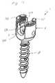
Figs. 1 to 4 . As can be seen in the exploded view ofFig. 2 , the bone anchoring element 1 of the first embodiment comprises ashank 2, ahead 3 provided separately from theshank 2, areceiving part 4 and apressure element 5. Further, in the first embodiment aring 7 is provided which will be described in detail below. - As can be seen in
Fig. 4a , theshank 2 comprises atip 20, a first portion 21 which is provided with abone thread 22, and asecond portion 23 adjacent to thefree end 27 opposite to thetip 20 which has a cylindrical surface. Thesecond portion 23 has a substantially smooth surface. Further, acircumferential groove 24 is provided in the outer surface of thesecond portion 23. Thefree end 27 of thesecond portion 23 has a beveled shape such that the diameter tapers towards thefree end 27. - As can be seen in
Fig. 3 , theshank 2 is further provided with acoaxial bore 25. Thebore 25 is open at thefree end 27 and extends to a predetermined distance from thetip 20. Lateral through-holes 26 can be provided in the first portion 21 which extend from thebore 25 to the outer surface of the first portion. The through-holes 26 can be arranged in the base of thebone thread 22 between the thread crests. Thebore 25 and the through-holes 26 allow, for example, introduction of bone cement to enhance the fixation of theshank 2 in the bone. Thefree end 27 of the shank further comprises a recess for engagement with a screwing-in tool. - The
head 3 has a substantially sleeve-like shape with afirst end 32 and asecond end 33. Theouter surface 30 is shaped as a segment of a sphere. A cylindrical bore 31 is provided which extends through the head from thefirst end 32 to thesecond end 33. Acircumferential groove 34 is provided approximately at the center of the cylindrical bore 31. As can be seen inFigs. 3 and4b , thegroove 34 has a substantially rectangular cross-section. - Further, a
longitudinal slit 35 is provided in thehead 3 which extends from thefirst end 32 to thesecond end 33. Although only oneslit 35 which extends from thefirst end 32 to thesecond end 33 is shown in the embodiment, the slit does not have to extend continuously from thefirst end 32 to thesecond end 33. One slit extending from thefirst end 32 or thesecond end 33 to a predetermined distance from the respective other end may be provided. As an alternative, for example, several slits which alternately extend from thefirst end 32 to a predetermined distance from thesecond end 33 and from thesecond end 33 to a predetermined distance from thefirst end 32 may be provided. The slit in thehead 3 serves to provide elasticity to thehead 3 in order to allow insertion even of a slightly oversized shank, as will be described below, and to provide secure clamping after final locking with a securing element. - The
ring 7 is provided as a snap ring which has a substantially annular shape with aclearance 70, as can be seen inFig. 4c . Thering 7 has a substantially rectangular cross-section and is shaped such that it fits in thegroove 24 on thesecond portion 23 of theshank 2 and in thegroove 34 in the cylindrical bore 31 of thehead 3. Due to theclearance 70 thering 7 has certain flexibility, i.e. its diameter can be enlarged and decreased by a certain amount. - As can be seen in
Figs. 2 and3 , the receivingpart 4 has a substantially cylindrical shape with afirst end 40 and asecond end 41 and a longitudinal axis Z. Acoaxial bore 42 extends through the receivingpart 4 from thefirst end 40 to thesecond end 41. The shape of thelongitudinal bore 42 tapers towards thefirst end 40 such that aseat 43 for accommodating theouter surface 30 of thehead 3 is formed. The seat can have, for example, a spherical shape or a conical shape or another tapering shape. Further, a substantiallyU-shaped recess 44 is formed in the receivingpart 4 adjacent to thesecond end 41 such that twofree legs bore 42 for receiving arod 60. On the inner surface of thefree legs second end 41 aninner thread 47 is provided for screwing-in a securing element 61 for securing therod 60 in the U-shaped recess. In the embodiment theinner thread 47 is designed as a flat thread having the thread flanks arranged perpendicular to the longitudinal axis. However, the thread can have any other suited thread shape. - Further, as shown in
Fig. 2 thepressure element 5 has a substantially cylindrical shape and is dimensioned such that it can be inserted in thecoaxial bore 42 of the receivingpart 4 and is slidably guided therein. On its upper side thepressure element 5 has arecess 52 shaped as a segment of a hollow cylinder the diameter of which substantially corresponds to the diameter of the bottom of theU-shaped recess 44 of the receivingpart 4. On thelower side 51 of the pressure element 5 a recess (not shown) shaped as a segment of a hollow sphere is provided the diameter of which substantially corresponds to the outer diameter of thehead 3. A bore 53 is provided in thepressure element 5 coaxially to its cylinder axis in order to allow guiding through of a screwing-in tool. In use, thepressure element 5 is placed in thelongitudinal bore 42 such that therecess 52 shaped as a segment of a hollow cylinder is aligned with theU-shaped recess 44, as can be seen inFig. 1 . - The operation of the bone anchoring device 1 of the first embodiment will now be described with reference to
Fig. 5 . - In operation, first the
shank 2 can be screwed into a bone or vertebra by engagement with a screwing-in tool. - The receiving
part 4, thehead 3, thering 7 and thepressure element 5 can be provided in a preassembled state. In the pre-assembled state thering 7 is inserted in the cylindrical bore 31 of thehead 3 such that it rests in the ring-shapedgroove 34. Further, thehead 3 is placed in thelongitudinal bore 42 of the receivingpart 4 such that it rests on theseat 43 and remains pivotable with respect to the receivingpart 4. Thepressure element 5 is placed in thelongitudinal bore 42 of the receivingpart 4 such that the recess on thelower side 51 faces theouter surface 30 of thehead 3 and such that therecess 52 shaped as a segment of a hollow cylinder is aligned with theU-shaped recess 44. In this assembled state, due to the flexibility provided by theclearance 70, thering 7 can still be expanded such that its diameter is enlarged. Further, due to theslit 35, thehead 3 can still be expanded such that its diameter is enlarged. - The assembly of receiving
part 4,head 3,ring 7 andpressure element 5 can then be connected to theshank 2 by guiding thesecond portion 23 of theshank 2 into the cylindrical bore 31 of thehead 3. The beveled shape of the upperfree end 27 of theshank 2 facilitates insertion. During insertion thehead 3 and thering 7 are slightly expanded by thesecond portion 23 of the shank until thering 7 snaps into thegroove 24 of thesecond portion 23 of the shank. In this condition thering 7 rests in thegroove 24 of the end portion of theshank 2 and in thegroove 34 of thehead 3. As a result, theshank 2 is prevented from retracting again from thehead 3 by form-locking engagement of thering 7 in thegroove 34 in thehead 3. - The cylindrical shape of the
second portion 23 of theshank 2 allows easy and convenient insertion of theshank 2 into thehead 3. The projection formed by thering 7 arranged in thegroove 24 on theshank 2 allows secure fixation of theshank 2 to thehead 3 by form-locking. - After insertion of the
shank 2 in thehead 3, the angular orientation of theshank 2 relative to the cylinder axis Z of the receivingpart 4 can still be varied. In operation then a rod can be placed in theU-shaped recess 44 such that it rests in therecess 52 shaped as a segment of a hollow cylinder of thepressure element 5. A securing element can be screwed-in between thelegs inner thread 47. The securing element exerts pressure on the rod and the rod in turn exerts pressure on thepressure element 5. As a result, thepressure element 5 presses on thehead 3 and the angular orientation of thehead 3 relative to the receivingpart 4 is thereby fixed. Further, since thehead 3 is pressed against theseat 43 which is formed in a tapered shape, thehead 3 is slightly compressed and the connection of theshank 2 to thehead 3 is further strengthened. - The slit in the
head 3 provides certain elasticity to thehead 3. Thus, ashank 2 having a slightly over-dimensionedsecond portion 23 can be connected to thehead 3. Further, this elasticity provides secure clamping of theshank 2 in thehead 3, when the securing element is fastened. - It has been described above that the
shank 2 is first screwed into the bone or vertebra before connecting it to thehead 3. Alternatively theshank 2 can first be connected to thehead 3 and the receiving part, such that the anchoring element is in a pre-assembled state, and thereafter theshank 2 can be screwed into the bone or vertebra by guiding a screwing-in tool through thelongitudinal bore 42 of the receivingpart 4 and through thebore 53 of thepressure element 5 into the structure in thelongitudinal bore 25 of theshank 2. Thus, variability is ensured. - A second embodiment will be described with reference to
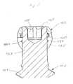
Figs. 6 to 9 . The second embodiment differs from the first embodiment in the structure of the shank and the head. The receivingpart 4 and thepressure element 5 are identical to those of the first embodiment and will not be described again. The receivingpart 4 and thepressure element 5 are omitted inFigs. 6 to 9 . - The
shank 102 according to the second embodiment comprises afirst portion 121 which is provided with a bone thread 122 and asecond portion 123 having a cylindrical outer surface with a first diameter wherein the surface is substantially smooth. As can be seen inFigs. 8 and9 , theshank 102 does not have a longitudinal bore as the shank in the first embodiment. Arecess 126 for engagement with a screwing-in tool is provided at the free end 127. As in the first embodiment the free end 127 of theshank 102 has a beveled shape to facilitate insertion of theshank 102 into the head 103. - A circumferentially extending projection 107 is formed on the
second portion 123. The projection 107 is formed integrally with thesecond portion 123. - Similar to the first embodiment, the head 103 has a substantially sleeve-like shape. The
outer surface 130 is shaped as a segment of a sphere and cylindrical bore 131 is provided. A circumferential groove 134 is provided approximately at the center of the cylindrical bore 131. - Further, a plurality of longitudinal slits 135 are provided in the head 103 which alternately extend from the
first end 132 to a predetermined distance from thesecond end 133 and from thesecond end 133 to a predetermined distance from thefirst end 132. This structure of the slits 135 provides a uniform flexibility to the head 103 in the region of thefirst end 132 and in the region of thesecond end 133. - Operation of the second embodiment is similar to the first embodiment. When the free end 127 of the
shank 102 is inserted into the cylindrical bore 131 of the head 103, the diameter of the head 103 becomes enlarged by introduction of the circular projection 107. When the projection 107 reaches the ring-shaped groove 134 in the cylindrical bore 131, the head 103 elastically contracts and the projection 107 rests in the groove 134 such that theshank 102 is prevented from retracting from the cylindrical bore 131. After assembly of the complete bone anchoring device the pressure transmitted via thepressure element 5 further enhances the fixation of theshank 102 in the head 103 similar to the first embodiment. - According to the first embodiment, a projection projecting from the cylindrical outer surface of the
second portion 23 of theshank 2 is formed by thering 7 which is placed in agroove 24 in theshank 2. Similarly in the second embodiment a projection projecting from the cylindrical outer surface of thesecond portion 123 of theshank 102 is formed by the circular projection 107 which is integrally formed with thesecond portion 123. In both cases, easy and convenient insertion of theshank head 3, 103 is allowed due to the cylindrical shape of the outer surface of thesecond portion shank projection 7, 107 projecting from the outer surface of thesecond portion groove 34, 134 provided in thehead 3, 103. Theslits 35, 135 provide flexibility to therespective head 3, 103 which further facilitates insertion. - A third embodiment is shown in
Figs. 10 and11 . The third embodiment differs from the first and second embodiments in the structure of the head and the pressure element. The further structure is similar to that of the first and second embodiments and will not be described again. - The bone anchoring devices of the first and second embodiments provides a so-called polyaxial connection of the
shank part 4. In contrast, the bone anchoring device according to the third embodiment provides a monoaxial connection between ashank 202 and the receivingpart 4. Theshank 202 is constructed similar to theshank 2 in the first embodiment with afirst portion 221, a cylindricalsecond portion 223 adjacent to a free end 227, and with agroove 224, but without a longitudinal bore and without through-holes. - As can be seen in
Fig. 10 , in the third embodiment the head and the pressure element are not constructed as separate parts but are formed in one piece as ahead 203. Thehead 203 has a substantially cylindrical shape with a cylindrical outer surface 230 dimensioned such that it can be inserted in thelongitudinal bore 42 of the receivingpart 4. At afirst end 203a the outer diameter of thehead 203 tapers in a spherical shape. The opposite second end 203b is formed similar to theupper side 50 of thepressure element 5 in the first embodiment, i.e. a cylindrically-shaped recess 252 is formed at the second end 203b. A plurality ofslits 235 extend from thefirst end 203a to a predetermined distance from the second end 203b. Theslits 235 serve to provide flexibility to thehead 203. Again, only oneslit 235 may be provided alternatively. - The
head 203 has a cylindrical bore 231 and a ring-shaped groove 234 similar to thehead 3 in the first embodiment. - Assembly of the third embodiment is similar to the first embodiment. In operation, the
head 203 is inserted in thelongitudinal bore 42 of the receivingpart 4. Thesnap ring 7 is placed in thegroove 224 on thesecond portion 223. Then, the cylindricalsecond portion 223 of theshank 202 is inserted into the cylindrical bore 231 of thehead 203 and thehead 203 slightly widens due to the flexibility provided by theslits 235. Theshank 202 is inserted until thesnap ring 7 faces the ring-shaped groove 234 provided in thehead 203 and then, due to the flexibility of thehead 203, thesnap ring 7 engages with the groove 234. As a result, theshank 202 is prevented from retracting again from thehead 203. - After insertion of the
rod 60 the securing element 61 is inserted for locking therod 60 in the receivingpart 4. During tightening of the securing element 61 pressure acts on the second end 203b of thehead 203. Thehead 203 is pressed towards thefirst end 40 of the receivingpart 4. Due to the tapering shape of thelongitudinal bore 42 and to theslits 235 provided in thehead 203, thehead 203 is compressed and theshank 202 becomes securely locked in thehead 203. - In an alternative way of operation the snap ring can first be placed in the ring-shaped groove 234 of the
head 203 and thereafter theshank 202 can be inserted. - In a further modification of the polyaxial bone anchoring device the shank is formed similarly to the
shank 2 in the first embodiment with agroove 24 provided in the cylindrical outer surface of thesecond section 23. In contrast to the first embodiment thering 7 is omitted and, instead of the ring-shapedgroove 34 in the cylindrical bore 31 of thehead 3, a ring-shaped projection with a reduced diameter as compared to the cylindrical bore 31 is integrally formed in the cylindrical bore 31. When theshank 2 is inserted in the cylindrical bore 31, this ring-shaped projection engages with thegroove 24 of theshank 2. - As a result, a similar connection as that described with respect to the first and the second embodiments can be achieved. This structure can also be applied to the monoaxial connection shown in the third embodiment.
- The
ring 7 in the first and third embodiment can be considered to form a projection provided on the cylindrical inner surface of the bore 31, 231. The projection formed by thering 7 engages with thegroove shank - The structure of the projection 107 of the second embodiment cooperating with a groove provided in the head can be applied to the monoaxial connection of the third embodiment.
- Although embodiments have been described in which locking of the rod and the angular orientation of the shank in the polyaxial bone anchoring device is performed by one single securing element, it is also possible to provide two securing elements for independently fixing the rod and the head. Alternatively, the securing element can be formed by an outer nut which is screwed on an outer thread provided on the free legs of the receiving part.
- In the embodiments above the pressure element has a groove in the upper surface. However, it is also possible to provide a pressure element with a flat upper surface.
- Further modifications are possible. For example the features of the head according to the second embodiment can be combined with the shank according to the first embodiment and vice versa.
- Different types of shanks with or without coaxial bores and with different types of bone threads can be provided such that a modular system is formed. In such a system, also hooks may be provided. Further, different types of heads may be provided which can be combined with the shanks depending on the respective application. In this way, a modular system can be provided which offers variability in application.
Claims (10)
- A bone anchoring device with
a shank (2, 102, 202) to be anchored in a bone or vertebra, a head (3, 103, 203), and a receiving part (4) receiving the head (3, 103, 203) for connecting the shank (2, 102, 202) to a rod,
the shank (2, 102, 202) and the head (3, 103, 203) being separate parts,
the head (3, 103, 203) having a bore (31, 131, 231) with an inner surface, and at least one slit (35, 135, 235) extending from the inner surface to the outer surface (30, 130, 230) of the head (3, 103, 203) and
the shank (2, 102, 202) having a first portion (21, 121, 221) for anchoring in the bone or vertebra and a second portion (23, 123, 223) with an outer surface adjoining a free end (27, 127, 227), wherein a projection (7, 107) is provided on one of the outer surface of the second portion (23, 123, 223) or the inner surface of the head (3, 103, 203); and
a ring-shaped groove (34, 134, 234; 24, 224) is provided on the other one of the inner surface of the head (3, 103, 203) and the outer surface of the second portion (23, 123, 223);
the projection (7, 107) and the groove (34, 134, 234; 24, 224) engage with each other, when the second portion (23, 123, 223) of the shank (2, 102, 202) is inserted in the bore (31, 131, 231) of the head (3, 103, 203),
characterised in that
the inner surface of the bore (31, 131, 231) of the head (3, 103, 203) being cylindrical and
the outer surface of the second portion (23, 123, 223) of the shank (2, 102, 202) being cylindrical. - The bone anchoring device according to claim 1, wherein the projection (7, 107) is ring-shaped.
- The bone anchoring device according to claims 1 or 2, wherein the outer surface of the head (30, 130) is substantially shaped as a segment of a sphere.
- The bone anchoring device according to one of claims 1 to 3, wherein the bore (31, 131, 231) penetrates the head (3, 103, 203) from a first end (32, 132) to a second end (33, 133).
- The bone anchoring device according to one of claims 1 to 4, wherein the at least one slit (35, 135, 235) extends from the first end (32, 132) to the second end (33, 133) of the head (3, 103, 203).
- The bone anchoring device according to one of claims 1 to 5, wherein several slits (135) are provided in the head (103) which alternately extend from the first end (132) to a predetermined distance from the second end (133) and from the second end (133) to a predetermined distance from the first end (132), respectively.
- The bone anchoring device according to one of claims 1 to 6, wherein a longitudinal bore (42) passes through the receiving part from a first end (40) to a second end (41) and the longitudinal bore has a tapered shape adjacent to the second end (41) forming a seat (43) for accommodating the head (3, 103).
- The bone anchoring device according to one of claims 1 to 7, wherein a pressure element (5) is arranged in the longitudinal bore (42) for fixing the angular orientation of the shank (2) relative to the receiving part (4).
- The bone anchoring device according to one of claims 1 to 8, wherein a U-shaped recess (44) is formed in the receiving part (4) adjacent to the first end (40) and extending substantially perpendicular to the longitudinal bore (42) such that two free legs (45, 46) are formed constituting a channel for receiving the rod.
- Modular system comprising the bone anchoring device according to one of claims 1 to 9, wherein a plurality of different shanks (2, 102, 202) and/or a plurality of different heads (3, 103, 203) are provided.
Applications Claiming Priority (1)
| Application Number | Priority Date | Filing Date | Title |
|---|---|---|---|
| EP20060024232EP1925263B1 (en) | 2006-11-22 | 2006-11-22 | Bone anchoring device |
Related Parent Applications (1)
| Application Number | Title | Priority Date | Filing Date |
|---|---|---|---|
| EP06024232.8Division | 2006-11-22 |
Publications (2)
| Publication Number | Publication Date |
|---|---|
| EP2272451A1 EP2272451A1 (en) | 2011-01-12 |
| EP2272451B1true EP2272451B1 (en) | 2012-04-04 |
Family
ID=37943746
Family Applications (3)
| Application Number | Title | Priority Date | Filing Date |
|---|---|---|---|
| EP20090000228ActiveEP2039310B1 (en) | 2006-11-22 | 2006-11-22 | Bone anchoring device |
| EP20060024232ActiveEP1925263B1 (en) | 2006-11-22 | 2006-11-22 | Bone anchoring device |
| EP20100186166ActiveEP2272451B1 (en) | 2006-11-22 | 2006-11-22 | Bone anchoring device |
Family Applications Before (2)
| Application Number | Title | Priority Date | Filing Date |
|---|---|---|---|
| EP20090000228ActiveEP2039310B1 (en) | 2006-11-22 | 2006-11-22 | Bone anchoring device |
| EP20060024232ActiveEP1925263B1 (en) | 2006-11-22 | 2006-11-22 | Bone anchoring device |
Country Status (9)
| Country | Link |
|---|---|
| US (3) | US9119674B2 (en) |
| EP (3) | EP2039310B1 (en) |
| JP (2) | JP5579964B2 (en) |
| KR (1) | KR101586835B1 (en) |
| CN (1) | CN101185587B (en) |
| AT (1) | ATE551962T1 (en) |
| DE (1) | DE602006019616D1 (en) |
| ES (3) | ES2373770T3 (en) |
| TW (1) | TWI445516B (en) |
Cited By (2)
| Publication number | Priority date | Publication date | Assignee | Title |
|---|---|---|---|---|
| US11937857B2 (en) | 2013-03-14 | 2024-03-26 | DePuy Synthes Products, Inc. | Bone anchors and surgical instruments with integrated guide tips |
| US12127766B2 (en) | 2021-03-05 | 2024-10-29 | Medos International Sàrl | Selectively locking polyaxial screw |
Families Citing this family (138)
| Publication number | Priority date | Publication date | Assignee | Title |
|---|---|---|---|---|
| US7833250B2 (en) | 2004-11-10 | 2010-11-16 | Jackson Roger P | Polyaxial bone screw with helically wound capture connection |
| US7862587B2 (en) | 2004-02-27 | 2011-01-04 | Jackson Roger P | Dynamic stabilization assemblies, tool set and method |
| US8353932B2 (en) | 2005-09-30 | 2013-01-15 | Jackson Roger P | Polyaxial bone anchor assembly with one-piece closure, pressure insert and plastic elongate member |
| US8876868B2 (en) | 2002-09-06 | 2014-11-04 | Roger P. Jackson | Helical guide and advancement flange with radially loaded lip |
| WO2006052796A2 (en) | 2004-11-10 | 2006-05-18 | Jackson Roger P | Helical guide and advancement flange with break-off extensions |
| US7621918B2 (en) | 2004-11-23 | 2009-11-24 | Jackson Roger P | Spinal fixation tool set and method |
| US6716214B1 (en) | 2003-06-18 | 2004-04-06 | Roger P. Jackson | Polyaxial bone screw with spline capture connection |
| US7377923B2 (en) | 2003-05-22 | 2008-05-27 | Alphatec Spine, Inc. | Variable angle spinal screw assembly |
| US8398682B2 (en) | 2003-06-18 | 2013-03-19 | Roger P. Jackson | Polyaxial bone screw assembly |
| US8377102B2 (en) | 2003-06-18 | 2013-02-19 | Roger P. Jackson | Polyaxial bone anchor with spline capture connection and lower pressure insert |
| US7967850B2 (en) | 2003-06-18 | 2011-06-28 | Jackson Roger P | Polyaxial bone anchor with helical capture connection, insert and dual locking assembly |
| US7766915B2 (en) | 2004-02-27 | 2010-08-03 | Jackson Roger P | Dynamic fixation assemblies with inner core and outer coil-like member |
| US8137386B2 (en) | 2003-08-28 | 2012-03-20 | Jackson Roger P | Polyaxial bone screw apparatus |
| US8926670B2 (en) | 2003-06-18 | 2015-01-06 | Roger P. Jackson | Polyaxial bone screw assembly |
| US7776067B2 (en) | 2005-05-27 | 2010-08-17 | Jackson Roger P | Polyaxial bone screw with shank articulation pressure insert and method |
| US20110040338A1 (en)* | 2003-08-28 | 2011-02-17 | Jackson Roger P | Polyaxial bone anchor having an open retainer with conical, cylindrical or curvate capture |
| US8366753B2 (en) | 2003-06-18 | 2013-02-05 | Jackson Roger P | Polyaxial bone screw assembly with fixed retaining structure |
| US7527638B2 (en) | 2003-12-16 | 2009-05-05 | Depuy Spine, Inc. | Methods and devices for minimally invasive spinal fixation element placement |
| US7179261B2 (en) | 2003-12-16 | 2007-02-20 | Depuy Spine, Inc. | Percutaneous access devices and bone anchor assemblies |
| US11419642B2 (en) | 2003-12-16 | 2022-08-23 | Medos International Sarl | Percutaneous access devices and bone anchor assemblies |
| US8152810B2 (en) | 2004-11-23 | 2012-04-10 | Jackson Roger P | Spinal fixation tool set and method |
| US7160300B2 (en) | 2004-02-27 | 2007-01-09 | Jackson Roger P | Orthopedic implant rod reduction tool set and method |
| US11241261B2 (en) | 2005-09-30 | 2022-02-08 | Roger P Jackson | Apparatus and method for soft spinal stabilization using a tensionable cord and releasable end structure |
| JP2007525274A (en) | 2004-02-27 | 2007-09-06 | ロジャー・ピー・ジャクソン | Orthopedic implant rod reduction instrument set and method |
| US7651502B2 (en) | 2004-09-24 | 2010-01-26 | Jackson Roger P | Spinal fixation tool set and method for rod reduction and fastener insertion |
| US8926672B2 (en) | 2004-11-10 | 2015-01-06 | Roger P. Jackson | Splay control closure for open bone anchor |
| US7875065B2 (en) | 2004-11-23 | 2011-01-25 | Jackson Roger P | Polyaxial bone screw with multi-part shank retainer and pressure insert |
| US9168069B2 (en) | 2009-06-15 | 2015-10-27 | Roger P. Jackson | Polyaxial bone anchor with pop-on shank and winged insert with lower skirt for engaging a friction fit retainer |
| WO2006057837A1 (en) | 2004-11-23 | 2006-06-01 | Jackson Roger P | Spinal fixation tool attachment structure |
| US8444681B2 (en) | 2009-06-15 | 2013-05-21 | Roger P. Jackson | Polyaxial bone anchor with pop-on shank, friction fit retainer and winged insert |
| US9980753B2 (en) | 2009-06-15 | 2018-05-29 | Roger P Jackson | pivotal anchor with snap-in-place insert having rotation blocking extensions |
| US8308782B2 (en) | 2004-11-23 | 2012-11-13 | Jackson Roger P | Bone anchors with longitudinal connecting member engaging inserts and closures for fixation and optional angulation |
| US10076361B2 (en) | 2005-02-22 | 2018-09-18 | Roger P. Jackson | Polyaxial bone screw with spherical capture, compression and alignment and retention structures |
| US7901437B2 (en) | 2007-01-26 | 2011-03-08 | Jackson Roger P | Dynamic stabilization member with molded connection |
| US12102357B2 (en) | 2005-02-22 | 2024-10-01 | Roger P. Jackson | Pivotal bone anchor assembly with cannulated shank having a planar top surface and method of assembly |
| US12357348B2 (en) | 2005-09-30 | 2025-07-15 | Roger P. Jackson | Method of assembling a pivotal bone anchor assembly with press-in-place insert |
| US8133262B2 (en)* | 2006-04-28 | 2012-03-13 | Depuy Spine, Inc. | Large diameter bone anchor assembly |
| US20080015576A1 (en)* | 2006-04-28 | 2008-01-17 | Whipple Dale E | Large diameter bone anchor assembly |
| US8361129B2 (en) | 2006-04-28 | 2013-01-29 | Depuy Spine, Inc. | Large diameter bone anchor assembly |
| CA2670988C (en) | 2006-12-08 | 2014-03-25 | Roger P. Jackson | Tool system for dynamic spinal implants |
| US10792074B2 (en) | 2007-01-22 | 2020-10-06 | Roger P. Jackson | Pivotal bone anchor assemly with twist-in-place friction fit insert |
| US8979904B2 (en) | 2007-05-01 | 2015-03-17 | Roger P Jackson | Connecting member with tensioned cord, low profile rigid sleeve and spacer with torsion control |
| US7947065B2 (en)* | 2008-11-14 | 2011-05-24 | Ortho Innovations, Llc | Locking polyaxial ball and socket fastener |
| US8007522B2 (en) | 2008-02-04 | 2011-08-30 | Depuy Spine, Inc. | Methods for correction of spinal deformities |
| US7909857B2 (en)* | 2008-03-26 | 2011-03-22 | Warsaw Orthopedic, Inc. | Devices and methods for correcting spinal deformities |
| ES2368016T3 (en) | 2008-04-22 | 2011-11-11 | Biedermann Motech Gmbh | INSTRUMENT FOR MOUNTING A BONE ANCHORAGE DEVICE. |
| ES2375526T3 (en)* | 2008-06-19 | 2012-03-01 | Biedermann Motech Gmbh | BONE ANCHORAGE ASSEMBLY. |
| EP2140824B1 (en)* | 2008-07-01 | 2016-06-08 | Biedermann Technologies GmbH & Co. KG | Cannulated bone anchor with plug member and tool for inserting the plug member into the bone anchor |
| AU2010260521C1 (en) | 2008-08-01 | 2013-08-01 | Roger P. Jackson | Longitudinal connecting member with sleeved tensioned cords |
| EP2745789B1 (en) | 2008-10-30 | 2017-04-19 | Depuy Spine Inc. | Systems for delivering bone cement to a bone anchor |
| WO2010065648A1 (en)* | 2008-12-02 | 2010-06-10 | Eminent Spine Llc | Pedicle screw fixation system and method for use of same |
| WO2010123859A2 (en)* | 2009-04-20 | 2010-10-28 | Osteo Innovations Llc | System and method for self filling bone screws |
| US11229457B2 (en)* | 2009-06-15 | 2022-01-25 | Roger P. Jackson | Pivotal bone anchor assembly with insert tool deployment |
| US11464549B2 (en) | 2009-06-15 | 2022-10-11 | Roger P. Jackson | Pivotal bone anchor assembly with horizontal tool engagement grooves and insert with upright arms having flared outer portions |
| CN103826560A (en) | 2009-06-15 | 2014-05-28 | 罗杰.P.杰克逊 | Polyaxial Bone Anchor with Socket Stem and Winged Inserts with Friction Fit Compression Collars |
| US9668771B2 (en) | 2009-06-15 | 2017-06-06 | Roger P Jackson | Soft stabilization assemblies with off-set connector |
| US8998959B2 (en) | 2009-06-15 | 2015-04-07 | Roger P Jackson | Polyaxial bone anchors with pop-on shank, fully constrained friction fit retainer and lock and release insert |
| US9707019B2 (en) | 2009-08-11 | 2017-07-18 | Zimmer Spine, Inc. | System and method for performing vertebral reduction using a sleeve |
| EP2548525B1 (en)* | 2009-09-25 | 2014-04-02 | Biedermann Technologies GmbH & Co. KG | Bone anchoring device |
| EP2485654B1 (en) | 2009-10-05 | 2021-05-05 | Jackson P. Roger | Polyaxial bone anchor with non-pivotable retainer and pop-on shank, some with friction fit |
| US8361123B2 (en) | 2009-10-16 | 2013-01-29 | Depuy Spine, Inc. | Bone anchor assemblies and methods of manufacturing and use thereof |
| RU2712028C2 (en) | 2009-11-09 | 2020-01-24 | Спайнуэлдинг Аг | Medical device for implantation into human or animal body or for strengthening of human or animal solid tissue for further implantation of separate implant and dental implant |
| ES2525046T3 (en)* | 2009-12-21 | 2014-12-16 | Biedermann Technologies Gmbh & Co. Kg | Bone anchoring device |
| EP2737865B1 (en) | 2010-01-08 | 2016-04-20 | Biedermann Technologies GmbH & Co. KG | Bone screw |
| TWI383771B (en)* | 2010-01-08 | 2013-02-01 | Rotary bone nails for orthopedics | |
| US12383311B2 (en) | 2010-05-14 | 2025-08-12 | Roger P. Jackson | Pivotal bone anchor assembly and method for use thereof |
| JP5797748B2 (en)* | 2010-05-19 | 2015-10-21 | デピュイ・シンセス・プロダクツ・インコーポレイテッド | Bone anchor |
| US8641717B2 (en) | 2010-07-01 | 2014-02-04 | DePuy Synthes Products, LLC | Guidewire insertion methods and devices |
| US9345519B1 (en)* | 2010-07-02 | 2016-05-24 | Presidio Surgical, Inc. | Pedicle screw |
| AU2011324058A1 (en) | 2010-11-02 | 2013-06-20 | Roger P. Jackson | Polyaxial bone anchor with pop-on shank and pivotable retainer |
| EP2457527B1 (en) | 2010-11-24 | 2014-04-16 | Biedermann Technologies GmbH & Co. KG | Polyaxial bone anchoring device with enlarged pivot angle |
| EP2460484A1 (en)* | 2010-12-01 | 2012-06-06 | FACET-LINK Inc. | Variable angle bone screw fixation assembly |
| ES2461843T3 (en)* | 2010-12-23 | 2014-05-21 | Biedermann Technologies Gmbh & Co. Kg | Bone anchoring device |
| JP5865479B2 (en) | 2011-03-24 | 2016-02-17 | ロジャー・ピー・ジャクソン | Multiaxial bone anchor with compound joint and pop-mounted shank |
| US9155580B2 (en) | 2011-08-25 | 2015-10-13 | Medos International Sarl | Multi-threaded cannulated bone anchors |
| EP2574296B1 (en)* | 2011-09-28 | 2016-03-02 | Biedermann Technologies GmbH & Co. KG | Bone anchoring assembly |
| US9622788B2 (en)* | 2011-11-02 | 2017-04-18 | Warsaw Orthopedic, Inc. | Implant assembly with a rigid interface |
| WO2013082576A1 (en) | 2011-12-01 | 2013-06-06 | Eminent Spine Llc | Bone screw |
| US8911479B2 (en) | 2012-01-10 | 2014-12-16 | Roger P. Jackson | Multi-start closures for open implants |
| US20130211467A1 (en)* | 2012-02-10 | 2013-08-15 | Warsaw Orthopedic, Inc. | Connector and fastener system |
| ES2527766T3 (en)* | 2012-05-29 | 2015-01-29 | Biedermann Technologies Gmbh & Co. Kg | Receiver piece for receiving and housing a bar in order to couple it with a bone anchoring element, and bone anchoring device with such a receiving piece |
| US9510866B2 (en)* | 2012-08-15 | 2016-12-06 | Blackstone Medical, Inc. | Pivoting spinal fixation devices |
| US9782204B2 (en) | 2012-09-28 | 2017-10-10 | Medos International Sarl | Bone anchor assemblies |
| US8911478B2 (en) | 2012-11-21 | 2014-12-16 | Roger P. Jackson | Splay control closure for open bone anchor |
| US10058354B2 (en) | 2013-01-28 | 2018-08-28 | Roger P. Jackson | Pivotal bone anchor assembly with frictional shank head seating surfaces |
| US9486249B2 (en)* | 2013-02-14 | 2016-11-08 | Blackstone Medical, Inc. | Rod attachment assembly for occipital plate |
| US8852239B2 (en) | 2013-02-15 | 2014-10-07 | Roger P Jackson | Sagittal angle screw with integral shank and receiver |
| US9724145B2 (en) | 2013-03-14 | 2017-08-08 | Medos International Sarl | Bone anchor assemblies with multiple component bottom loading bone anchors |
| US20140277155A1 (en)* | 2013-03-14 | 2014-09-18 | K2M, Inc. | Taper lock hook |
| US20140277153A1 (en) | 2013-03-14 | 2014-09-18 | DePuy Synthes Products, LLC | Bone Anchor Assemblies and Methods With Improved Locking |
| US10342582B2 (en) | 2013-03-14 | 2019-07-09 | DePuy Synthes Products, Inc. | Bone anchor assemblies and methods with improved locking |
| US20140277159A1 (en) | 2013-03-14 | 2014-09-18 | DePuy Synthes Products, LLC | Bottom-loading bone anchor assemblies |
| US9259247B2 (en) | 2013-03-14 | 2016-02-16 | Medos International Sarl | Locking compression members for use with bone anchor assemblies and methods |
| US9775660B2 (en) | 2013-03-14 | 2017-10-03 | DePuy Synthes Products, Inc. | Bottom-loading bone anchor assemblies and methods |
| GB2512063B (en)* | 2013-03-18 | 2019-05-29 | Fitzbionics Ltd | Spinal implant assembly |
| DE102014219270A1 (en)* | 2013-10-01 | 2015-04-16 | Silony Medical International AG | Polyaxial bone screw for surgical medical purposes and osteosynthesis device |
| US9566092B2 (en) | 2013-10-29 | 2017-02-14 | Roger P. Jackson | Cervical bone anchor with collet retainer and outer locking sleeve |
| EP2873383B1 (en)* | 2013-11-14 | 2016-10-19 | Biedermann Technologies GmbH & Co. KG | Polyaxial bone anchoring device with enlarged pivot angle |
| US9717533B2 (en) | 2013-12-12 | 2017-08-01 | Roger P. Jackson | Bone anchor closure pivot-splay control flange form guide and advancement structure |
| US9451993B2 (en) | 2014-01-09 | 2016-09-27 | Roger P. Jackson | Bi-radial pop-on cervical bone anchor |
| US20150230828A1 (en)* | 2014-02-20 | 2015-08-20 | K2M, Inc. | Spinal fixation device |
| US10064658B2 (en) | 2014-06-04 | 2018-09-04 | Roger P. Jackson | Polyaxial bone anchor with insert guides |
| US9597119B2 (en) | 2014-06-04 | 2017-03-21 | Roger P. Jackson | Polyaxial bone anchor with polymer sleeve |
| US11219471B2 (en) | 2014-10-21 | 2022-01-11 | Roger P. Jackson | Pivotal bone anchor receiver having an insert with post-placement tool deployment |
| US9924975B2 (en) | 2014-10-21 | 2018-03-27 | Roger P. Jackson | Bone anchor having a snap-fit assembly |
| US10543021B2 (en) | 2014-10-21 | 2020-01-28 | Roger P. Jackson | Pivotal bone anchor assembly having an open ring positioner for a retainer |
| CN104873309B (en)* | 2015-06-02 | 2017-07-11 | 北京纳通科技集团有限公司 | A kind of pedicle screw fixation system |
| AU2016247221B2 (en)* | 2015-10-23 | 2021-03-11 | K2M, Inc. | Semi-constrained bone screw and insertion instrument |
| US10426455B2 (en)* | 2016-02-04 | 2019-10-01 | Westek, LLC | Surgical anchor and method of use |
| US10463402B2 (en) | 2016-07-13 | 2019-11-05 | Medos International Sàrl | Bone anchor assemblies and related instrumentation |
| US10568667B2 (en) | 2016-07-13 | 2020-02-25 | Medos International Sàrl | Bone anchor assemblies and related instrumentation |
| US10363073B2 (en) | 2016-07-13 | 2019-07-30 | Medos International Sàrl | Bone anchor assemblies and related instrumentation |
| US10874438B2 (en) | 2016-07-13 | 2020-12-29 | Medos International Sarl | Bone anchor assemblies and related instrumentation |
| US11109895B2 (en)* | 2016-10-26 | 2021-09-07 | Warsaw Orthopedic, Inc. | Spinal construct |
| US11298156B2 (en) | 2017-03-30 | 2022-04-12 | K2M, Inc. | Modular screw |
| AU2018243875B2 (en) | 2017-03-30 | 2022-05-26 | K2M, Inc. | Bone anchor apparatus and method of use thereof |
| WO2018183486A1 (en) | 2017-03-30 | 2018-10-04 | K2M, Inc. | Modular offset screw |
| US11147602B2 (en)* | 2017-05-04 | 2021-10-19 | Warsaw Orthopedic, Inc. | Spinal implant system and method |
| CN107669323B (en)* | 2017-10-20 | 2020-05-29 | 北京爱康宜诚医疗器材有限公司 | Orthopedic built-in connectors and connector mounting templates |
| US10695100B2 (en)* | 2017-12-15 | 2020-06-30 | Warsaw Orthopedic, Inc. | Spinal implant system and methods of use |
| US10966762B2 (en) | 2017-12-15 | 2021-04-06 | Medos International Sarl | Unilateral implant holders and related methods |
| US11596449B2 (en) | 2018-09-13 | 2023-03-07 | Roger P. Jackson | Pivotal bone anchor assembly with modular receiver and universal shank head |
| WO2020102787A1 (en) | 2018-11-16 | 2020-05-22 | Surber, James L. | Pivotal bone anchor assembly having a deployable collet insert with internal pressure ring |
| USD1004774S1 (en) | 2019-03-21 | 2023-11-14 | Medos International Sarl | Kerrison rod reducer |
| US11291481B2 (en) | 2019-03-21 | 2022-04-05 | Medos International Sarl | Rod reducers and related methods |
| US11291482B2 (en) | 2019-03-21 | 2022-04-05 | Medos International Sarl | Rod reducers and related methods |
| WO2021034664A1 (en) | 2019-08-14 | 2021-02-25 | K2M, Inc. | Pedicle fixation system |
| WO2021127251A1 (en)* | 2019-12-17 | 2021-06-24 | Jackson Roger P | Bone anchor assembly with closed ring retainer and internal snap ring |
| WO2021263088A1 (en) | 2020-06-26 | 2021-12-30 | K2M, Inc. | Modular head assembly |
| EP3949882B1 (en)* | 2020-08-05 | 2023-10-11 | Biedermann Technologies GmbH & Co. KG | Bone anchoring device |
| EP4240262B1 (en) | 2020-11-09 | 2024-12-04 | Medos International Sàrl | Biplanar forceps reducers |
| WO2022108875A1 (en) | 2020-11-19 | 2022-05-27 | K2M, Inc. | Modular head assembly for spinal fixation |
| US12364515B2 (en)* | 2021-03-05 | 2025-07-22 | Medos International Sàrl | Multi-feature polyaxial screw |
| CN113171166B (en)* | 2021-04-26 | 2022-06-14 | 宁波兆盈医疗器械有限公司 | Multipurpose pedicle screw, preparation method and fixing method thereof |
| US11751915B2 (en) | 2021-07-09 | 2023-09-12 | Roger P. Jackson | Modular spinal fixation system with bottom-loaded universal shank heads |
| US12053209B2 (en) | 2022-01-18 | 2024-08-06 | Roger P. Jackson | Spinal fixation systems with modular receiver and ring retainer sub-assemblies for connecting with universal shank heads |
| US11771473B2 (en)* | 2022-02-04 | 2023-10-03 | Phoenyx Spinal Technologies, Inc. | Polyaxial pedicle screw |
| US12414801B2 (en) | 2022-11-03 | 2025-09-16 | Roger P. Jackson | Spinal fixation system with modular receiver sub-assemblies for connecting with bi-spherical universal shank heads |
Family Cites Families (22)
| Publication number | Priority date | Publication date | Assignee | Title |
|---|---|---|---|---|
| US5242443A (en)* | 1991-08-15 | 1993-09-07 | Smith & Nephew Dyonics, Inc. | Percutaneous fixation of vertebrae |
| JP3308271B2 (en)* | 1992-06-25 | 2002-07-29 | ジンテーズ アクチエンゲゼルシャフト,クール | Osteosynthesis fixation device |
| SE9402130D0 (en)* | 1994-06-17 | 1994-06-17 | Sven Olerud | Device and method for plate fixation of legs |
| US6454769B2 (en)* | 1997-08-04 | 2002-09-24 | Spinal Concepts, Inc. | System and method for stabilizing the human spine with a bone plate |
| US6113601A (en)* | 1998-06-12 | 2000-09-05 | Bones Consulting, Llc | Polyaxial pedicle screw having a loosely coupled locking cap |
| US6331179B1 (en)* | 2000-01-06 | 2001-12-18 | Spinal Concepts, Inc. | System and method for stabilizing the human spine with a bone plate |
| DE10115014A1 (en) | 2001-03-27 | 2002-10-24 | Biedermann Motech Gmbh | anchoring element |
| DE10157969C1 (en)* | 2001-11-27 | 2003-02-06 | Biedermann Motech Gmbh | Element used in spinal and accident surgery comprises a shaft joined to a holding element having a U-shaped recess with two free arms having an internal thread with flanks lying at right angles to the central axis of the holding element |
| DE10246177A1 (en)* | 2002-10-02 | 2004-04-22 | Biedermann Motech Gmbh | Anchor element consists of screw with head, bone-thread section on shank and holder joining rod-shaped part to screw. with cavities in wall, and thread-free end of shank |
| US7175625B2 (en)* | 2002-11-25 | 2007-02-13 | Triage Medical | Soft tissue anchor and method of using same |
| US7044953B2 (en)* | 2003-02-27 | 2006-05-16 | Stryker Leibinger Gmbh & Co. Kg | Compression bone screw |
| US7635379B2 (en)* | 2003-05-02 | 2009-12-22 | Applied Spine Technologies, Inc. | Pedicle screw assembly with bearing surfaces |
| US8652175B2 (en) | 2003-05-02 | 2014-02-18 | Rachiotek, Llc | Surgical implant devices and systems including a sheath member |
| US20050182401A1 (en)* | 2003-05-02 | 2005-08-18 | Timm Jens P. | Systems and methods for spine stabilization including a dynamic junction |
| WO2006002333A2 (en)* | 2003-05-02 | 2006-01-05 | Applied Spine Technologies, Inc. | Systems and methods for spine stabilization |
| US7322981B2 (en) | 2003-08-28 | 2008-01-29 | Jackson Roger P | Polyaxial bone screw with split retainer ring |
| US7195633B2 (en)* | 2004-01-08 | 2007-03-27 | Robert J. Medoff | Fracture fixation system |
| US7186255B2 (en) | 2004-08-12 | 2007-03-06 | Atlas Spine, Inc. | Polyaxial screw |
| US7306606B2 (en)* | 2004-12-15 | 2007-12-11 | Orthopaedic Innovations, Inc. | Multi-axial bone screw mechanism |
| EP1741396B1 (en)* | 2005-07-08 | 2009-09-23 | BIEDERMANN MOTECH GmbH | Bone anchoring device |
| US20070118117A1 (en)* | 2005-10-20 | 2007-05-24 | Ebi, L.P. | Bone fixation assembly |
| WO2007075454A1 (en)* | 2005-12-19 | 2007-07-05 | Synthes (U.S.A) | Polyaxial bone anchor with headless pedicle screw |
- 2006
- 2006-11-22ESES09000228Tpatent/ES2373770T3/enactiveActive
- 2006-11-22DEDE200660019616patent/DE602006019616D1/enactiveActive
- 2006-11-22ESES10186166Tpatent/ES2385440T3/enactiveActive
- 2006-11-22EPEP20090000228patent/EP2039310B1/enactiveActive
- 2006-11-22EPEP20060024232patent/EP1925263B1/enactiveActive
- 2006-11-22EPEP20100186166patent/EP2272451B1/enactiveActive
- 2006-11-22ESES06024232Tpatent/ES2359848T3/enactiveActive
- 2006-11-22ATAT10186166Tpatent/ATE551962T1/enactive
- 2007
- 2007-11-19JPJP2007299470Apatent/JP5579964B2/enactiveActive
- 2007-11-19TWTW96143632Apatent/TWI445516B/ennot_activeIP Right Cessation
- 2007-11-19CNCN2007101870153Apatent/CN101185587B/enactiveActive
- 2007-11-19KRKR1020070117859Apatent/KR101586835B1/enactiveActive
- 2007-11-21USUS11/944,167patent/US9119674B2/enactiveActive
- 2009
- 2009-10-30USUS12/609,800patent/US9486245B2/enactiveActive
- 2014
- 2014-02-14JPJP2014026603Apatent/JP5968929B2/enactiveActive
- 2015
- 2015-07-29USUS14/813,017patent/US9788865B2/enactiveActive
Cited By (2)
| Publication number | Priority date | Publication date | Assignee | Title |
|---|---|---|---|---|
| US11937857B2 (en) | 2013-03-14 | 2024-03-26 | DePuy Synthes Products, Inc. | Bone anchors and surgical instruments with integrated guide tips |
| US12127766B2 (en) | 2021-03-05 | 2024-10-29 | Medos International Sàrl | Selectively locking polyaxial screw |
Also Published As
| Publication number | Publication date |
|---|---|
| TWI445516B (en) | 2014-07-21 |
| CN101185587B (en) | 2012-01-04 |
| DE602006019616D1 (en) | 2011-02-24 |
| JP5579964B2 (en) | 2014-08-27 |
| JP2008126082A (en) | 2008-06-05 |
| US20080132957A1 (en) | 2008-06-05 |
| CN101185587A (en) | 2008-05-28 |
| US20160022322A1 (en) | 2016-01-28 |
| EP2039310A3 (en) | 2009-04-08 |
| US9788865B2 (en) | 2017-10-17 |
| EP2272451A1 (en) | 2011-01-12 |
| EP2039310B1 (en) | 2011-09-14 |
| US20100049255A1 (en) | 2010-02-25 |
| US9486245B2 (en) | 2016-11-08 |
| ES2385440T3 (en) | 2012-07-24 |
| US9119674B2 (en) | 2015-09-01 |
| JP5968929B2 (en) | 2016-08-10 |
| EP1925263B1 (en) | 2011-01-12 |
| ES2373770T3 (en) | 2012-02-08 |
| ES2359848T3 (en) | 2011-05-27 |
| EP2039310A2 (en) | 2009-03-25 |
| ATE551962T1 (en) | 2012-04-15 |
| JP2014158711A (en) | 2014-09-04 |
| EP1925263A1 (en) | 2008-05-28 |
| KR101586835B1 (en) | 2016-01-20 |
| TW200829205A (en) | 2008-07-16 |
| KR20080046571A (en) | 2008-05-27 |
Similar Documents
| Publication | Publication Date | Title |
|---|---|---|
| EP2272451B1 (en) | Bone anchoring device | |
| US11992243B2 (en) | Bone anchoring device | |
| US11793552B2 (en) | Receiving part for receiving a rod for coupling the rod to a bone anchoring element and a bone anchoring device with such a receiving part | |
| EP2335625B1 (en) | Bone anchoring device | |
| EP2111811B1 (en) | Instrument for assembling a bone anchoring device | |
| US10064659B2 (en) | Polyaxial bone anchoring device with enlarged pivot angle | |
| KR101559859B1 (en) | A receiver for receiving the rod to connect the rod to the bone fixation element and a bone fixation device | |
| EP2204129B1 (en) | Receiving part for receiving a rod for coupling the rod to a bone anchoring element and a bone anchoring device with such a receiving part | |
| EP1943971A2 (en) | Locking assembly for bone anchoring device | |
| US20100160976A1 (en) | Receiving part for receiving a rod for coupling the rod to a bone anchoring element and a bone anchoring device with such a receiving part | |
| EP2674123A1 (en) | Polyaxial bone anchoring device | |
| US9510868B2 (en) | Polyaxial bone anchoring device | |
| CA2486292C (en) | Device for connecting a longitudinal carrier to a bone fixation means | |
| EP1749489B1 (en) | Bone anchoring device |
Legal Events
| Date | Code | Title | Description |
|---|---|---|---|
| PUAI | Public reference made under article 153(3) epc to a published international application that has entered the european phase | Free format text:ORIGINAL CODE: 0009012 | |
| AC | Divisional application: reference to earlier application | Ref document number:1925263 Country of ref document:EP Kind code of ref document:P | |
| AK | Designated contracting states | Kind code of ref document:A1 Designated state(s):AT BE BG CH CY CZ DE DK EE ES FI FR GB GR HU IE IS IT LI LT LU LV MC NL PL PT RO SE SI SK TR | |
| 17P | Request for examination filed | Effective date:20110712 | |
| GRAP | Despatch of communication of intention to grant a patent | Free format text:ORIGINAL CODE: EPIDOSNIGR1 | |
| GRAS | Grant fee paid | Free format text:ORIGINAL CODE: EPIDOSNIGR3 | |
| GRAA | (expected) grant | Free format text:ORIGINAL CODE: 0009210 | |
| AC | Divisional application: reference to earlier application | Ref document number:1925263 Country of ref document:EP Kind code of ref document:P | |
| AK | Designated contracting states | Kind code of ref document:B1 Designated state(s):AT BE BG CH CY CZ DE DK EE ES FI FR GB GR HU IE IS IT LI LT LU LV MC NL PL PT RO SE SI SK TR | |
| REG | Reference to a national code | Ref country code:GB Ref legal event code:FG4D | |
| REG | Reference to a national code | Ref country code:CH Ref legal event code:EP Ref country code:CH Ref legal event code:NV Representative=s name:NOVAGRAAF INTERNATIONAL SA | |
| REG | Reference to a national code | Ref country code:AT Ref legal event code:REF Ref document number:551962 Country of ref document:AT Kind code of ref document:T Effective date:20120415 | |
| REG | Reference to a national code | Ref country code:IE Ref legal event code:FG4D | |
| RAP2 | Party data changed (patent owner data changed or rights of a patent transferred) | Owner name:BIEDERMANN TECHNOLOGIES GMBH & CO. KG | |
| REG | Reference to a national code | Ref country code:DE Ref legal event code:R096 Ref document number:602006028682 Country of ref document:DE Effective date:20120531 | |
| REG | Reference to a national code | Ref country code:ES Ref legal event code:FG2A Ref document number:2385440 Country of ref document:ES Kind code of ref document:T3 Effective date:20120724 | |
| REG | Reference to a national code | Ref country code:DE Ref legal event code:R082 Ref document number:602006028682 Country of ref document:DE Representative=s name:PRUEFER & PARTNER MBB PATENTANWAELTE RECHTSANW, DE Ref country code:NL Ref legal event code:VDEP Effective date:20120404 Ref country code:DE Ref legal event code:R082 Ref document number:602006028682 Country of ref document:DE Representative=s name:PRUEFER & PARTNER GBR, DE | |
| REG | Reference to a national code | Ref country code:CH Ref legal event code:PUE Owner name:BIEDERMANN TECHNOLOGIES GMBH & CO.KG Free format text:BIEDERMANN MOTECH GMBH#BERTA-SUTTNER-STRASSE 23#78054 VILLINGEN-SCHWENNINGEN (DE) -TRANSFER TO- BIEDERMANN TECHNOLOGIES GMBH & CO.KG#JOSEFSTRASSE 5#78166 DONAUESCHINGEN (DE) | |
| REG | Reference to a national code | Ref country code:AT Ref legal event code:MK05 Ref document number:551962 Country of ref document:AT Kind code of ref document:T Effective date:20120404 | |
| LTIE | Lt: invalidation of european patent or patent extension | Effective date:20120404 | |
| PG25 | Lapsed in a contracting state [announced via postgrant information from national office to epo] | Ref country code:IS Free format text:LAPSE BECAUSE OF FAILURE TO SUBMIT A TRANSLATION OF THE DESCRIPTION OR TO PAY THE FEE WITHIN THE PRESCRIBED TIME-LIMIT Effective date:20120804 Ref country code:SE Free format text:LAPSE BECAUSE OF FAILURE TO SUBMIT A TRANSLATION OF THE DESCRIPTION OR TO PAY THE FEE WITHIN THE PRESCRIBED TIME-LIMIT Effective date:20120404 Ref country code:SI Free format text:LAPSE BECAUSE OF FAILURE TO SUBMIT A TRANSLATION OF THE DESCRIPTION OR TO PAY THE FEE WITHIN THE PRESCRIBED TIME-LIMIT Effective date:20120404 Ref country code:CY Free format text:LAPSE BECAUSE OF FAILURE TO SUBMIT A TRANSLATION OF THE DESCRIPTION OR TO PAY THE FEE WITHIN THE PRESCRIBED TIME-LIMIT Effective date:20120404 Ref country code:PL Free format text:LAPSE BECAUSE OF FAILURE TO SUBMIT A TRANSLATION OF THE DESCRIPTION OR TO PAY THE FEE WITHIN THE PRESCRIBED TIME-LIMIT Effective date:20120404 Ref country code:FI Free format text:LAPSE BECAUSE OF FAILURE TO SUBMIT A TRANSLATION OF THE DESCRIPTION OR TO PAY THE FEE WITHIN THE PRESCRIBED TIME-LIMIT Effective date:20120404 Ref country code:LT Free format text:LAPSE BECAUSE OF FAILURE TO SUBMIT A TRANSLATION OF THE DESCRIPTION OR TO PAY THE FEE WITHIN THE PRESCRIBED TIME-LIMIT Effective date:20120404 | |
| PG25 | Lapsed in a contracting state [announced via postgrant information from national office to epo] | Ref country code:PT Free format text:LAPSE BECAUSE OF FAILURE TO SUBMIT A TRANSLATION OF THE DESCRIPTION OR TO PAY THE FEE WITHIN THE PRESCRIBED TIME-LIMIT Effective date:20120806 Ref country code:GR Free format text:LAPSE BECAUSE OF FAILURE TO SUBMIT A TRANSLATION OF THE DESCRIPTION OR TO PAY THE FEE WITHIN THE PRESCRIBED TIME-LIMIT Effective date:20120705 Ref country code:LV Free format text:LAPSE BECAUSE OF FAILURE TO SUBMIT A TRANSLATION OF THE DESCRIPTION OR TO PAY THE FEE WITHIN THE PRESCRIBED TIME-LIMIT Effective date:20120404 | |
| PG25 | Lapsed in a contracting state [announced via postgrant information from national office to epo] | Ref country code:BE Free format text:LAPSE BECAUSE OF FAILURE TO SUBMIT A TRANSLATION OF THE DESCRIPTION OR TO PAY THE FEE WITHIN THE PRESCRIBED TIME-LIMIT Effective date:20120404 | |
| PG25 | Lapsed in a contracting state [announced via postgrant information from national office to epo] | Ref country code:SK Free format text:LAPSE BECAUSE OF FAILURE TO SUBMIT A TRANSLATION OF THE DESCRIPTION OR TO PAY THE FEE WITHIN THE PRESCRIBED TIME-LIMIT Effective date:20120404 Ref country code:RO Free format text:LAPSE BECAUSE OF FAILURE TO SUBMIT A TRANSLATION OF THE DESCRIPTION OR TO PAY THE FEE WITHIN THE PRESCRIBED TIME-LIMIT Effective date:20120404 Ref country code:AT Free format text:LAPSE BECAUSE OF FAILURE TO SUBMIT A TRANSLATION OF THE DESCRIPTION OR TO PAY THE FEE WITHIN THE PRESCRIBED TIME-LIMIT Effective date:20120404 Ref country code:EE Free format text:LAPSE BECAUSE OF FAILURE TO SUBMIT A TRANSLATION OF THE DESCRIPTION OR TO PAY THE FEE WITHIN THE PRESCRIBED TIME-LIMIT Effective date:20120404 Ref country code:NL Free format text:LAPSE BECAUSE OF FAILURE TO SUBMIT A TRANSLATION OF THE DESCRIPTION OR TO PAY THE FEE WITHIN THE PRESCRIBED TIME-LIMIT Effective date:20120404 Ref country code:CZ Free format text:LAPSE BECAUSE OF FAILURE TO SUBMIT A TRANSLATION OF THE DESCRIPTION OR TO PAY THE FEE WITHIN THE PRESCRIBED TIME-LIMIT Effective date:20120404 Ref country code:DK Free format text:LAPSE BECAUSE OF FAILURE TO SUBMIT A TRANSLATION OF THE DESCRIPTION OR TO PAY THE FEE WITHIN THE PRESCRIBED TIME-LIMIT Effective date:20120404 | |
| PLBE | No opposition filed within time limit | Free format text:ORIGINAL CODE: 0009261 | |
| STAA | Information on the status of an ep patent application or granted ep patent | Free format text:STATUS: NO OPPOSITION FILED WITHIN TIME LIMIT | |
| 26N | No opposition filed | Effective date:20130107 | |
| REG | Reference to a national code | Ref country code:GB Ref legal event code:732E Free format text:REGISTERED BETWEEN 20130307 AND 20130313 | |
| REG | Reference to a national code | Ref country code:DE Ref legal event code:R097 Ref document number:602006028682 Country of ref document:DE Effective date:20130107 | |
| REG | Reference to a national code | Ref country code:FR Ref legal event code:TP Owner name:BIEDERMANN TECHNOLOGIES GMBH & CO.KG, DE Effective date:20130329 | |
| PG25 | Lapsed in a contracting state [announced via postgrant information from national office to epo] | Ref country code:BG Free format text:LAPSE BECAUSE OF FAILURE TO SUBMIT A TRANSLATION OF THE DESCRIPTION OR TO PAY THE FEE WITHIN THE PRESCRIBED TIME-LIMIT Effective date:20120704 | |
| REG | Reference to a national code | Ref country code:IE Ref legal event code:MM4A | |
| PG25 | Lapsed in a contracting state [announced via postgrant information from national office to epo] | Ref country code:IE Free format text:LAPSE BECAUSE OF NON-PAYMENT OF DUE FEES Effective date:20121122 | |
| PG25 | Lapsed in a contracting state [announced via postgrant information from national office to epo] | Ref country code:TR Free format text:LAPSE BECAUSE OF FAILURE TO SUBMIT A TRANSLATION OF THE DESCRIPTION OR TO PAY THE FEE WITHIN THE PRESCRIBED TIME-LIMIT Effective date:20120404 Ref country code:MC Free format text:LAPSE BECAUSE OF NON-PAYMENT OF DUE FEES Effective date:20121130 | |
| PG25 | Lapsed in a contracting state [announced via postgrant information from national office to epo] | Ref country code:LU Free format text:LAPSE BECAUSE OF NON-PAYMENT OF DUE FEES Effective date:20121122 | |
| PG25 | Lapsed in a contracting state [announced via postgrant information from national office to epo] | Ref country code:HU Free format text:LAPSE BECAUSE OF FAILURE TO SUBMIT A TRANSLATION OF THE DESCRIPTION OR TO PAY THE FEE WITHIN THE PRESCRIBED TIME-LIMIT Effective date:20061122 | |
| REG | Reference to a national code | Ref country code:FR Ref legal event code:PLFP Year of fee payment:10 | |
| REG | Reference to a national code | Ref country code:FR Ref legal event code:PLFP Year of fee payment:11 | |
| REG | Reference to a national code | Ref country code:FR Ref legal event code:PLFP Year of fee payment:12 | |
| P01 | Opt-out of the competence of the unified patent court (upc) registered | Effective date:20230525 | |
| PGFP | Annual fee paid to national office [announced via postgrant information from national office to epo] | Ref country code:DE Payment date:20241125 Year of fee payment:19 | |
| PGFP | Annual fee paid to national office [announced via postgrant information from national office to epo] | Ref country code:GB Payment date:20241121 Year of fee payment:19 | |
| PGFP | Annual fee paid to national office [announced via postgrant information from national office to epo] | Ref country code:FR Payment date:20241126 Year of fee payment:19 | |
| PGFP | Annual fee paid to national office [announced via postgrant information from national office to epo] | Ref country code:IT Payment date:20241129 Year of fee payment:19 Ref country code:ES Payment date:20241213 Year of fee payment:19 | |
| PGFP | Annual fee paid to national office [announced via postgrant information from national office to epo] | Ref country code:CH Payment date:20241201 Year of fee payment:19 |