EP2268456B1 - Adapter part for a machine tool - Google Patents
Adapter part for a machine toolDownload PDFInfo
- Publication number
- EP2268456B1 EP2268456B1EP09732559.1AEP09732559AEP2268456B1EP 2268456 B1EP2268456 B1EP 2268456B1EP 09732559 AEP09732559 AEP 09732559AEP 2268456 B1EP2268456 B1EP 2268456B1
- Authority
- EP
- European Patent Office
- Prior art keywords
- adapter
- housing
- adapter part
- part according
- functional element
- Prior art date
- Legal status (The legal status is an assumption and is not a legal conclusion. Google has not performed a legal analysis and makes no representation as to the accuracy of the status listed.)
- Active
Links
Images


Classifications
- B—PERFORMING OPERATIONS; TRANSPORTING
- B25—HAND TOOLS; PORTABLE POWER-DRIVEN TOOLS; MANIPULATORS
- B25F—COMBINATION OR MULTI-PURPOSE TOOLS NOT OTHERWISE PROVIDED FOR; DETAILS OR COMPONENTS OF PORTABLE POWER-DRIVEN TOOLS NOT PARTICULARLY RELATED TO THE OPERATIONS PERFORMED AND NOT OTHERWISE PROVIDED FOR
- B25F5/00—Details or components of portable power-driven tools not particularly related to the operations performed and not otherwise provided for
- B25F5/02—Construction of casings, bodies or handles
- B—PERFORMING OPERATIONS; TRANSPORTING
- B25—HAND TOOLS; PORTABLE POWER-DRIVEN TOOLS; MANIPULATORS
- B25F—COMBINATION OR MULTI-PURPOSE TOOLS NOT OTHERWISE PROVIDED FOR; DETAILS OR COMPONENTS OF PORTABLE POWER-DRIVEN TOOLS NOT PARTICULARLY RELATED TO THE OPERATIONS PERFORMED AND NOT OTHERWISE PROVIDED FOR
- B25F5/00—Details or components of portable power-driven tools not particularly related to the operations performed and not otherwise provided for
- B25F5/006—Vibration damping means
Definitions
- the inventionrelates to an adapter part for a machine tool, in particular a hand tool.
- Hand tool machinessuch as drills, saws, angle grinders or the like have as drive to an electric motor whose rotor shaft is rotatably connected via a gear unit with a tool shaft as a support of a tool.
- a gear unitwith a tool shaft as a support of a tool.
- considerable mechanical loadscan occur which originate, on the one hand, from the vibrations of the drive motor, the gear unit and the tool shaft and the tool and, on the other hand, result from the machining of the workpiece, for example due to impacts or impacts.
- the vibrations and vibrationscan also lead to a significant noise pollution.
- the WO 2007/058596 A1discloses a cordless drill or - screwdriver having a one-piece motor and handle housing, wherein at the foot of the handle housing a detachable battery unit is arranged.
- the battery unitis positively connected to the housing foot by a guide shoulder on the housing of the battery unit can be inserted into a groove at the bottom of the handle housing.
- an adapter unitcan be inserted, which is a display unit or a receiving module for communication with a stationary control device may have.
- the inventionhas for its object to provide with simple measures a machine tool, in particular a hand tool, with additional functionality. It should be in particular at the option of the user a vibration damping element in a simple manner and remove.
- the adapter part according to the inventionis suitable for use for a machine tool, in particular a hand tool such as an angle grinder, wherein the housing of the machine tool is at least two parts and the two separate housing parts are coupled via a connecting device.
- the adapter partis inserted at the option of the user between the two housing parts and has for this purpose at least one adapter-connecting element, which is adapted to a housing-connecting element on one of the two housing parts.
- Thismakes it possible, without additional measures such as the use of auxiliary tools to insert the adapter part between the housing parts and connect via the adapter connector with the relevant housing parts.
- the adapter-connecting elementis expediently the same structure as the housing-connecting element, the connection between the housing part and the adapter part in a similar manner as the direct connection between the housing parts in the event that no adapter part is used.
- a functional elementis integrated, via which the desired functionality is generated.
- the functional elementis designed as a vibration damping element and serves for vibration reduction in the machine tool.
- functional elements with other functionalitiescome into consideration, for example, a lighting unit to illuminate the work area, a measuring device, a control unit or a display unit for displaying various state or operating variables of the machine tool such as the temperature.
- cooling modules or fan unitsmay also be provided as functional elements.
- the adapter partserves only for extension without additional function; In this case, the functional element forms an extension part.
- the functional elementis designed as an independent component, which is designed separately from the adapter connection element, so that a simple replacement of the functional element is also possible within the adapter part.
- a section of the functional elementextends axially beyond the receiving groove and at least partially covers the outer lateral surface of the adapter ring. This will be assembled in the Condition reaches an overlap in the housing in the adapter part receiving area.
- the adapter ringis formed elastically deformable.
- This embodimentis particularly suitable for a functional element, which is designed as a vibration damping element, since on the inherent elasticity of the adapter ring deformation due to the occurring vibrations or shocks is achieved and these deformations are reduced in the vibration damping element.
- the adapter ringis designed in such a way that the adapter-connecting element is arranged in the region of an end face of the adapter part on the radial outer side of the adapter ring.
- a latching of the adapter ringis achieved at this end face with the associated housing part.
- Another advantageis the ability to combine multiple adapter parts and put together to form a total adapter part.
- two or more, mutually identically constructed adapter partsare assembled axially one behind the other and inserted between the two housing parts of the machine tool.
- the individual adapter partscan have either identical or different functional elements.
- adapter connection elementson both end sides of the adapter part, which correspond with the respectively assigned housing connection parts.
- an adapter connection elementonly on one end side of the adapter part and to provide an adapter compensation element on the opposite end side, which is not brought into connection engagement with the facing housing connection element, but cup-shaped the relevant housing connection element engages, whereby a compact design is achieved in the axial direction.
- the connection on this end faceis expediently carried out via a separate connection device, for example via a screw connection.
- the housing 2 of the power toolfor example, a grinder such as an angle grinder, divided into two and consists of two detachably mounted to each other housing parts 2a and 2b, of which the first housing part 2a a handle housing and the second housing part 2b forms a motor housing for receiving an electric drive motor.
- the two housing parts 2a and 2babut each other at a separating edge, which is designated by the reference numeral 3.
- the connection between the housing parts 2a and 2bis preferably done manually and without auxiliary tool, as well as the release of the two housing parts 2a and 2b.
- housing connecting elementswhich are designed as housing latching elements 4 and 5 and respectively arranged on the housing parts 2a and 2b in the region of the end face facing one another latch into one another.
- the connectionis made by joining in the radial direction, so that in the axial direction, which also represents the release or mounting direction, there is a positive connection between the housing locking elements 4 and 5.
- the handle housing 2ais divided into two parts in the axial direction, which opens up the possibility of each approaching the two halves of the handle housing in the radial direction to the housing latching element 5 on the motor housing 2b.
- the housing locking element 5 on the housing part 2bis designed as an external thread, the housing locking element 4 on the housing part 2a accordingly as an internal thread. But it is also possible locking with only axial Verrastgraphy without rotation about the longitudinal axis of the power tool.
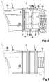
- Fig. 3the housing parts 2a and 2b of the power tool 1 are shown axially remote from each other, whereby a gap 6 between the housing parts is formed, in which an adapter part can be used.
- This adapter partis in Fig. 4 denoted by reference numeral 7 and comprises two axially spaced, parallel adapter rings 8a and 8b and a received between the adapter rings 8a, 8b functional element 9.
- the adapter part 7can be used in the space 6, if necessary, whereby the total length of the power tool 1 increases.
- the functional element 9takes on different tasks.
- the functional element 9is designed as a vibration damping element, which ensures a reduction of the vibration load in the housing of the power tool.
- a functional elementas a carrier of a lighting unit or a version with sensors, a control unit, a display unit or the like, are also possible.
- the adapter part 7assumes a force-transmitting function between the two housing parts 2a and 2b in the inserted state.
- the functional element 9as a vibration damping element
- the between the housing parts 2a and 2b extending adapter rings 8a, 8bhas a minimum of inherent elasticity, so that within narrow limits, a relative movement between the housing parts 2a and 2b may occur is damped by the functional element 9.
- an embodiment of the two adapter rings 8a, 8b made of a hard plasticis also possible, wherein the functional element 9, which consists of soft, damping material, axially connects the two adapter rings 8a and 8b.
- the adapter ring 8bwhich faces the housing part 2a, is provided in the region of its free axial end face with an adapter latching element 11 which is constructed in a corresponding manner as the housing latching element 4 on the housing part 2a, as a radially inwardly directed latching device is formed with a plurality of circumferential, parallel ratchet teeth or as a thread.
- the adapter part 7can be brought to the housing part 2a in a connecting or locking position, in the same manner as in a direct connection of the two housing parts together.
- an adapter compensation element 10is provided on the adapter ring 8a on the housing part 2b facing side, which is cup-shaped and the housing locking element 5 overlaps, so that in the axial direction, a compact design is given.
- the housing latching element 5is designed as a radially outwardly extending latching device, for example as an external thread.
- a force-transmitting connection between the adapter compensation element 10 and the housing latching element 5does not take place; Rather, the connection between the adapter part 7 and the housing part 2b is made via an additional connection means 12, which is designed for example as a screw connection and may comprise a plurality of screws distributed over the circumference, with which the adapter ring 8a is screwed to the housing part 2b.
- the adapter compensation element 10is designed as an adapter connecting element, which is adapted to the associated housing connecting element 5.
- the connecting device 12is not required.
- the functional element 9has an axially projecting lip 9a, which covers the adapter ring 8a in the region of the adapter compensation element 10 up to the end face. Since the axially opposite adapter locking element 11 is overlapped in the mounted position of the housing locking element 4, thus covering the functional element 9, the gap in which the adapter part 7 is inserted in the axial direction completely.
- FIGS. 5 and 6a further embodiment is shown in which two individual adapter parts 7 are inserted axially one behind the other and are connected to the two housing parts 2a and 2b.
- the Functional element 9 in the two adapter partsmay possibly differ.
Landscapes
- Engineering & Computer Science (AREA)
- Mechanical Engineering (AREA)
- Constituent Portions Of Griding Lathes, Driving, Sensing And Control (AREA)
- Component Parts Of Construction Machinery (AREA)
- Casings For Electric Apparatus (AREA)
- Vibration Prevention Devices (AREA)
- Auxiliary Devices For Machine Tools (AREA)
- Grinding-Machine Dressing And Accessory Apparatuses (AREA)
- Portable Power Tools In General (AREA)
Description
Translated fromGermanDie Erfindung bezieht sich auf ein Adapterteil für eine Werkzeugmaschine, insbesondere eine Handwerkzeugmaschine.The invention relates to an adapter part for a machine tool, in particular a hand tool.
Handwerkzeugmaschinen wie Bohrer, Sägen, Winkelschleifer oder dergleichen weisen als Antrieb einen Elektromotor auf, dessen Rotorwelle über eine Getriebeeinheit drehbar mit einer Werkzeugwelle als Träger eines Werkzeuges verbunden ist. Im Betrieb der Handwerkzeugmaschine können erhebliche mechanische Belastungen auftreten, die zum einen von den Schwingungen des Antriebsmotors, der Getriebeeinheit und der Werkzeugwelle sowie des Werkzeuges stammen und zum anderen von der Bearbeitung des Werkstückes herrühren, beispielsweise durch Stöße oder Schläge. Die Schwingungen und Vibrationen können auch zu einer erheblichen Geräuschbelastung führen.Hand tool machines such as drills, saws, angle grinders or the like have as drive to an electric motor whose rotor shaft is rotatably connected via a gear unit with a tool shaft as a support of a tool. During operation of the power tool, considerable mechanical loads can occur which originate, on the one hand, from the vibrations of the drive motor, the gear unit and the tool shaft and the tool and, on the other hand, result from the machining of the workpiece, for example due to impacts or impacts. The vibrations and vibrations can also lead to a significant noise pollution.
Die
Optional kann zwischen den Griffgehäusefuß und das Akkupack eine Adaptereinheit eingeschoben werden, die eine Anzeigeeinheit oder ein Empfangsmodul zur Kommunikation mit einer stationären Steuerungseinrichtung aufweisen kann.Optionally, between the handle housing foot and the battery pack, an adapter unit can be inserted, which is a display unit or a receiving module for communication with a stationary control device may have.
Der Erfindung liegt die Aufgabe zugrunde, mit einfachen Maßnahmen eine Werkzeugmaschine, insbesondere eine Handwerkzeugmaschine, mit zusätzlicher Funktionalität auszustatten. Es soll insbesondere nach Wahl des Anwenders ein Schwingungsdämpfungselement in einfacher Weise ein- und auszubauen sein.The invention has for its object to provide with simple measures a machine tool, in particular a hand tool, with additional functionality. It should be in particular at the option of the user a vibration damping element in a simple manner and remove.
Diese Aufgabe wird erfindungsgemäß mit den Merkmalen des Anspruches 1 gelöst. Die Unteransprüche geben zweckmäßige Weiterbildungen an.This object is achieved with the features of claim 1. The dependent claims indicate expedient developments.
Das erfindungsgemäße Adapterteil eignet sich zur Anwendung für eine Werkzeugmaschine, insbesondere eine Handwerkzeugmaschine wie zum Beispiel einen Winkelschleifer, wobei das Gehäuse der Werkzeugmaschine mindestens zweigeteilt ist und die beiden separaten Gehäuseteile über eine Verbindungseinrichtung gekoppelt sind. Das Adapterteil ist nach Wahl des Anwenders zwischen die beiden Gehäuseteile einzufügen und weist hierfür mindestens ein Adapter-Verbindungselement auf, das an ein Gehäuse-Verbindungselement an einem der beiden Gehäuseteile angepasst ist. Dadurch ist es möglich, ohne zusätzliche Maßnahmen wie die Verwendung von Hilfswerkzeugen das Adapterteil zwischen die Gehäuseteile einzufügen und über das Adapter-Verbindungselement mit dem betreffenden Gehäuseteile zu verbinden. Da das Adapter-Verbindungselement zweckmäßigerweise gleich aufgebaut ist wie das Gehäuse-Verbindungselement, erfolgt auch die Verbindung zwischen dem Gehäuseteil und dem Adapterteil in entsprechender Weise wie die direkte Verbindung zwischen den Gehäuseteilen für den Fall, dass kein Adapterteil eingesetzt wird.The adapter part according to the invention is suitable for use for a machine tool, in particular a hand tool such as an angle grinder, wherein the housing of the machine tool is at least two parts and the two separate housing parts are coupled via a connecting device. The adapter part is inserted at the option of the user between the two housing parts and has for this purpose at least one adapter-connecting element, which is adapted to a housing-connecting element on one of the two housing parts. This makes it possible, without additional measures such as the use of auxiliary tools to insert the adapter part between the housing parts and connect via the adapter connector with the relevant housing parts. Since the adapter-connecting element is expediently the same structure as the housing-connecting element, the connection between the housing part and the adapter part in a similar manner as the direct connection between the housing parts in the event that no adapter part is used.
Diese Ausführung ermöglicht einen schnellen Ein- und Ausbau des Adapterteils, wobei verschiedene Funktionalitäten im Adapterteil realisiert sein können. In das Adapterteil ist ein Funktionselement integriert, über das die gewünschte Funktionalität erzeugt wird. Das Funktionselement ist als Schwingungsdämpfungselement ausgebildet und dient zur Schwingungsreduzierung in der Werkzeugmaschine. Zusätzlich kommen aber auch Funktionselemente mit anderen Funktionalitäten in Betracht, beispielsweise eine Beleuchtungseinheit, um den Arbeitsbereich auszuleuchten, eine Messeinrichtung, eine Steuereinheit oder auch eine Anzeigeeinheit zur Anzeige diverser Zustands- oder Betriebsgrößen der Werkzeugmaschine wie beispielsweise die Temperatur. Gegebenenfalls können als Funktionselemente auch Kühlmodule oder Gebläseeinheiten vorgesehen sein. Gemäß einer besonders einfachen Ausführung dient das Adapterteil lediglich zur Verlängerung ohne darüber hinausgehende Funktion; in diesem Fall bildet das Funktionselement ein Verlängerungsteil.This design allows a quick installation and removal of the adapter part, wherein various functionalities can be implemented in the adapter part. In the adapter part, a functional element is integrated, via which the desired functionality is generated. The functional element is designed as a vibration damping element and serves for vibration reduction in the machine tool. In addition, however, functional elements with other functionalities come into consideration, for example, a lighting unit to illuminate the work area, a measuring device, a control unit or a display unit for displaying various state or operating variables of the machine tool such as the temperature. Optionally, cooling modules or fan units may also be provided as functional elements. According to a particularly simple embodiment, the adapter part serves only for extension without additional function; In this case, the functional element forms an extension part.
Das Funktionselement ist als ein eigenständiges Bauteil ausgebildet, welches separat von dem Adapter-Verbindungselement ausgeführt ist, so dass auch innerhalb des Adapterteils ein einfacher Austausch des Funktionselementes möglich ist.The functional element is designed as an independent component, which is designed separately from the adapter connection element, so that a simple replacement of the functional element is also possible within the adapter part.
Am Adapterteil sind zwei beabstandete, parallel angeordnete Adapterringe angeordnet, zwischen denen sich das Funktionselement befindet, wobei das Funktionselement zweckmäßigerweise die beiden Adapterringe miteinander verbindet, so dass die beiden Adapterringe und das Funktionselement eine bauliche Einheit bilden. Über diese Ausführung lässt sich in Achsrichtung eine optimale Dämpfung erzielen.On the adapter part, two spaced, parallel arranged adapter rings, between which the functional element is located, wherein the functional element expediently connects the two adapter rings together, so that the two adapter rings and the functional element form a structural unit. This version can be achieved in the axial direction optimum damping.
Es kann zweckmäßig sein, dass ein Abschnitt des Funktionselementes sich axial über die Aufnahmenut hinaus erstreckt und zumindest teilweise die äußere Mantelfläche des Adapterringes überdeckt. Dadurch wird im zusammengebauten Zustand eine Überdeckung im Gehäuse in dem das Adapterteil aufnehmenden Bereich erreicht.It may be expedient that a section of the functional element extends axially beyond the receiving groove and at least partially covers the outer lateral surface of the adapter ring. This will be assembled in the Condition reaches an overlap in the housing in the adapter part receiving area.
Gemäß einer weiteren vorteilhaften Ausführung ist der Adapterring elastisch verformbar ausgebildet. Diese Ausführung eignet sich insbesondere für ein Funktionselement, das als Schwingungsdämpfungselement ausgeführt ist, da über die Eigenelastizität des Adapterringes eine Verformung aufgrund der auftretenden Schwingungen oder Stöße erreicht wird und diese Verformungen im Schwingungsdämpfungselement reduziert werden.According to a further advantageous embodiment of the adapter ring is formed elastically deformable. This embodiment is particularly suitable for a functional element, which is designed as a vibration damping element, since on the inherent elasticity of the adapter ring deformation due to the occurring vibrations or shocks is achieved and these deformations are reduced in the vibration damping element.
Gemäß einer weiteren zweckmäßigen Ausführung ist der Adapterring in der Weise ausgeführt, dass das Adapter-Verbindungselement im Bereich einer Stirnseite des Adapterteils an der radialen Außenseite des Adapterringes angeordnet ist. In Kombination mit einer Ausführung der Verbindungselemente als Rastelemente wird eine Verrastung des Adapterringes an dieser Stirnseite mit dem zugeordneten Gehäuseteil erreicht. Der Vorteil dieser Ausführung liegt darin, dass eine axiale Überlappung zwischen der Stirnseite des Adapterringes und dem benachbarten Gehäuseteil erfolgt, und zwar in gleicher Weise wie die Überlappung zwischen den unmittelbar zusammengefügten Gehäuseteilen für den Fall, dass kein Adapterteil eingesetzt wird. Auch mit Adapterteil wird eine feste Verbindung zwischen den Gehäuseteilen erzielt, wobei die Qualität der Verbindung zumindest im Wesentlichen gleich ist wie bei unmittelbar miteinander verrasteten Gehäuseteilen.According to a further expedient embodiment of the adapter ring is designed in such a way that the adapter-connecting element is arranged in the region of an end face of the adapter part on the radial outer side of the adapter ring. In combination with an embodiment of the connecting elements as latching elements, a latching of the adapter ring is achieved at this end face with the associated housing part. The advantage of this embodiment is that an axial overlap between the end face of the adapter ring and the adjacent housing part takes place, in the same way as the overlap between the immediately assembled housing parts in the event that no adapter part is used. Even with adapter part a firm connection between the housing parts is achieved, wherein the quality of the connection is at least substantially the same as in directly latched together housing parts.
Ein weiterer Vorteil liegt in der Möglichkeit, mehrere Adapterteile zu kombinieren und zu einem Gesamt-Adapterteil zusammenzusetzen. In diesem Fall werden zwei oder mehrere, untereinander identisch aufgebaute Adapterteile axial hintereinander liegend zusammengesetzt und zwischen die beiden Gehäuseteile der Werkzeugmaschine eingefügt. Die einzelnen Adapterteile können hierbei entweder gleichartige oder auch unterschiedliche Funktionselemente aufweisen.Another advantage is the ability to combine multiple adapter parts and put together to form a total adapter part. In this case, two or more, mutually identically constructed adapter parts are assembled axially one behind the other and inserted between the two housing parts of the machine tool. The individual adapter parts can have either identical or different functional elements.
Es kann zweckmäßig sein, an beiden Stirnseiten des Adapterteils Adapter-Verbindungselemente vorzusehen, die mit den jeweils zugeordneten Gehäuse-Verbindungsteilen korrespondieren. Möglich ist es aber auch, nur an einer Stirnseite des Adapterteils ein Adapter-Verbindungselement anzuordnen und an der gegenüberliegenden Stirnseite ein Adapter-Kompensationselement vorzusehen, das nicht in einen Verbindungseingriff mit dem zugewandten Gehäuse-Verbindungselement gebracht wird, sondern das betreffende Gehäuse-Verbindungselement topfförmig übergreift, wodurch eine in Achsrichtung kompakte Ausführung erreicht wird. Die Verbindung an dieser Stirnseite wird zweckmäßigerweise über eine separate Verbindungseinrichtung durchgeführt, beispielsweise über eine Schraubverbindung.It may be expedient to provide adapter connection elements on both end sides of the adapter part, which correspond with the respectively assigned housing connection parts. However, it is also possible to arrange an adapter connection element only on one end side of the adapter part and to provide an adapter compensation element on the opposite end side, which is not brought into connection engagement with the facing housing connection element, but cup-shaped the relevant housing connection element engages, whereby a compact design is achieved in the axial direction. The connection on this end face is expediently carried out via a separate connection device, for example via a screw connection.
Weitere Vorteile und zweckmäßige Ausführungen sind den weiteren Ansprüchen, der Figurenbeschreibung und den Zeichnungen zu entnehmen. Es zeigen:
- Fig. 1
- eine schematische Darstellung des zweiteiligen Gehäuses einer Handwerkzeugmaschine, mit einem Griffgehäuse und einem Motorgehäuse in zusammengesetzter Position,
- Fig. 2
- eine Schnittdarstellung aus dem Verbindungsbereich zwischen den Gehäuseteilen,
- Fig. 3
- das Gehäuse der Handwerkzeugmaschine mit auseinander gezogenen Gehäuseteilen, wobei der Zwischenraum zwischen den Gehäuseteilen zur Aufnahme eines Adapterteils genutzt werden kann,
- Fig. 4
- eine Schnittdarstellung mit einem eingesetzten Adapterteil zwischen den beiden Gehäuseteilen,
- Fig. 5
- eine weitere Schnittdarstellung mit zwei axial hintereinander eingesetzten Adapterteilen,
- Fig. 6
- eine Seitenansicht auf das Gehäuse gemäß
Fig. 5 .
- Fig. 1
- a schematic representation of the two-part housing of a power tool, with a handle housing and a motor housing in the assembled position,
- Fig. 2
- a sectional view of the connection area between the housing parts,
- Fig. 3
- the housing of the power tool with pulled apart housing parts, wherein the space between the housing parts can be used to receive an adapter part,
- Fig. 4
- a sectional view with an inserted adapter part between the two housing parts,
- Fig. 5
- a further sectional view with two axially successively used adapter parts,
- Fig. 6
- a side view of the housing according to
Fig. 5 ,
In den Figuren sind gleiche Bauteile mit gleichen Bezugszeichen versehen.In the figures, the same components are provided with the same reference numerals.
Wie
Im zusammengefügten Zustand greifen Gehäuse-Verbindungselemente, die als Gehäuse-Rastelemente 4 und 5 ausgeführt und jeweils an den Gehäuseteilen 2a und 2b im Bereich einander zugewandten Stirnseite angeordnet sind, verrastend ineinander. Die Verbindung wird durch Zusammenfügen in Radialrichtung hergestellt, so dass in Achsrichtung, die zugleich die Löse- bzw. Montagerichtung darstellt, ein Formschluss zwischen den Gehäuse-Rastelementen 4 und 5 besteht. Zweckmäßigerweise ist das Griffgehäuse 2a in Achrichtung zweigeteilt, was die Möglichkeit eröffnet, die beiden Hälften des Griffgehäuses jeweils in Radialrichtung an das Gehäuse-Rastelement 5 am Motorgehäuse 2b anzunähern.In the assembled state, housing connecting elements which are designed as
Das Gehäuse-Rastelement 5 am Gehäuseteil 2b ist als Außengewinde ausgeführt, das Gehäuse-Rastelement 4 am Gehäuseteil 2a dementsprechend als Innengewinde. Möglich ist aber auch eine Verrastung mit ausschließlich axialer Verrastbewegung ohne Drehung um die Längsachse der Handwerkzeugmaschine.The
In
Das Adapterteil 7 übernimmt im eingesetzten Zustand eine kraftübertragende Funktion zwischen den beiden Gehäuseteilen 2a und 2b. Im Falle einer Ausführung des Funktionselements 9 als Schwingungsdämpfungselement kann es zweckmäßig sein, dass die sich zwischen den Gehäuseteilen 2a und 2b erstreckenden Adapterringe 8a, 8b ein Mindestmaß an Eigenelastizität aufweist, damit innerhalb enger Grenzen eine Relativbewegung zwischen den Gehäuseteilen 2a und 2b auftreten kann, die von dem Funktionselement 9 gedämpft wird. Möglich ist aber auch eine Ausführung der beiden Adapterringe 8a, 8b aus einem Hartkunststoff, wobei das Funktionselement 9, welches aus weichem, dämpfenden Material besteht, die beiden Adapterringe 8a und 8b axial miteinander verbindet.The
Der Adapterring 8b, der dem Gehäuseteil 2a zugewandt ist, ist im Bereich seiner freien axialen Stirnseite mit einem Adapter-Rastelement 11 versehen, das in korrespondierender Weise aufgebaut ist wie das Gehäuse-Rastelement 4 an dem Gehäuseteil 2a, das als radial nach innen gerichtete Rasteinrichtung mit mehreren umlaufenden, parallelen Rastzähnen oder als Gewinde ausgebildet ist. Dadurch kann das Adapterteil 7 mit dem Gehäuseteil 2a in eine Verbindungs- bzw. Rastposition gebracht werden, und zwar in gleicher Weise wie bei einer unmittelbaren Verbindung der beiden Gehäuseteile miteinander.The
Wie
Gegebenenfalls ist auch das Adapter-Kompensationselement 10 als Adapter-Verbindungselement ausgeführt, das an das zugeordnete Gehäuse-Verbindungselement 5 angepasst ist. In diesem Fall ist die Verbindungseinrichtung 12 nicht erforderlich.Optionally, the
Das Funktionselement 9 weist eine axial überstehende Lippe 9a auf, die den Adapterring 8a im Bereich des Adapter-Kompensationselementes 10 bis zur Stirnseite überdeckt. Da das axial gegenüberliegende Adapter-Rastelement 11 in montierter Position von dem Gehäuse-Rastelement 4 übergriffen ist, deckt somit das Funktionselement 9 den Zwischenraum, in den das Adapterteil 7 eingesetzt ist, in Achsrichtung vollständig ab.The
In den
In der montierten Position sind die einander zugewandten Adapter-Rastelemente 10 und 11 im Bereich der Verbindung zwischen den einzelnen Adapterteilen 7 miteinander verrastet. Die Verbindung zwischen den jeweiligen Adapter-Rastelementen zu den Gehäuseteilen 2a und 2b erfolgt wie vorbeschrieben wie beim Ausführungsbeispiel gemäß
Claims (14)
- Adapter part for a machine tool, in particular a handheld machine tool (1), which has a housing (2) for accommodating and holding a drive unit and a tool, wherein the housing (2) has two separate housing parts (2a, 2b) which are to be connected to each other via a connecting device which comprises housing connecting elements (4, 5) on the housing parts (2a, 2b), with a functional element (9) assigned to the adapter part (7), wherein the adapter part (7) is to be fitted between the two housing parts (2a, 2b) and has at least one adapter connecting element (11) which is adapted to a housing connecting element (4) and is to be brought into a connecting position with the housing connecting element (4),characterized in that the housing parts (2a, 2b) respectively form a handle housing (2a) and a motor housing (2b) for accommodating an electric drive motor,in that the functional element (9) is designed as a vibration damping element,in that two adapter rings (8a, 8b) arranged in parallel are provided, between which the functional element (9) is arranged, andin that the adapter connecting element (11) is formed separately from the functional element (9) on an adapter ring (8a, 8b) which is a carrier of the functional element (9).
- Adapter part according to Claim 1,characterized in that the adapter ring (8a, 8b) is designed to be elastically deformable.
- Adapter part according to Claim 1 or 2,characterized in that, in the region of one end side, the adapter connecting element (11) is arranged on the radial outer side of the adapter ring (8b).
- Adapter part according to one of Claims 1 to 3,characterized in that an adapter compensation element (10) which is adapted to a housing connecting element (5) is formed in the region of the opposite end side.
- Adapter part according to Claim 4,characterized in that the housing connecting element (5) is arranged on the radial outer side of the housing part (2b) and the adapter compensation element (10) engages in a cup-shaped manner over the associated housing connecting element (5).
- Adapter part according to one of Claims 1 to 5,characterized in that the functional element (9) at least partially overlaps the outer lateral surface of the adapter ring (8b).
- Adapter part according to Claim one of Claims 1 to 6,characterized in that the functional element (9) connects the two adapter rings (8a, 8b) to each other.
- Adapter part according to one of Claims 1 to 7,characterized in that the functional element (9) at least substantially extends over the axial length of the adapter part (7).
- Adapter part according to one of Claims 1 to 8,characterized in that the housing connecting element (4) and the adapter connecting element (11) are designed as latching elements which can be brought into a latching position.
- Adapter part according to one of Claims 1 to 9,characterized in that a plurality of adapter parts (7) are to be assembled to form an entire adapter part.
- Adapter part according to one of Claims 1 to 10,characterized in that the functional element (9) comprises a measuring and/or control unit.
- Adapter part according to one of Claims 1 to 151,characterized in that the functional element (9) comprises a display unit.
- Adapter part according to one of Claims 1 to 12,characterized in that the functional element (9) comprises an illumination unit.
- Machine tool with an adapter part according to one of Claims 1 to 13.
Applications Claiming Priority (2)
| Application Number | Priority Date | Filing Date | Title |
|---|---|---|---|
| DE102008001266ADE102008001266A1 (en) | 2008-04-18 | 2008-04-18 | Adapter part for a machine tool |
| PCT/EP2009/053531WO2009127505A1 (en) | 2008-04-18 | 2009-03-25 | Adapter part for a machine tool |
Publications (2)
| Publication Number | Publication Date |
|---|---|
| EP2268456A1 EP2268456A1 (en) | 2011-01-05 |
| EP2268456B1true EP2268456B1 (en) | 2016-11-02 |
Family
ID=40666949
Family Applications (1)
| Application Number | Title | Priority Date | Filing Date |
|---|---|---|---|
| EP09732559.1AActiveEP2268456B1 (en) | 2008-04-18 | 2009-03-25 | Adapter part for a machine tool |
Country Status (6)
| Country | Link |
|---|---|
| US (1) | US8453757B2 (en) |
| EP (1) | EP2268456B1 (en) |
| CN (1) | CN102006972B (en) |
| DE (1) | DE102008001266A1 (en) |
| RU (1) | RU2516019C2 (en) |
| WO (1) | WO2009127505A1 (en) |
Families Citing this family (4)
| Publication number | Priority date | Publication date | Assignee | Title |
|---|---|---|---|---|
| US10464202B2 (en)* | 2012-03-05 | 2019-11-05 | Ingersoll-Rand Company | Power tools with titanium hammer cases and associated flange interfaces |
| GB201413008D0 (en) | 2014-07-23 | 2014-09-03 | Black & Decker Inc | A range of power tools |
| DE102018206872A1 (en)* | 2018-05-04 | 2019-11-07 | Robert Bosch Gmbh | grinding housing |
| MX2021014887A (en) | 2019-06-12 | 2022-01-18 | Milwaukee Electric Tool Corp | Rotary power tool. |
Family Cites Families (22)
| Publication number | Priority date | Publication date | Assignee | Title |
|---|---|---|---|---|
| SU925623A1 (en)* | 1980-09-08 | 1982-05-07 | Всесоюзный Научно-Исследовательский И Проектно-Конструкторский Институт Механизированного И Ручного Строительно-Монтажного Инструмента, Вибраторов И Строительно-Отделочных Машин | Unit for securing percussive-action machine working tool |
| DE3147418C2 (en)* | 1981-11-30 | 1986-05-22 | Black & Decker, Inc. (Eine Gesellschaft N.D.Ges.D. Staates Delaware), Newark, Del. | Insulating part for components of a power tool |
| US5361853A (en)* | 1991-11-29 | 1994-11-08 | Ryobi Limited | Power tool |
| RU2095234C1 (en)* | 1995-08-15 | 1997-11-10 | Борис Николаевич Стихановский | Rotatable-percussion mechanism |
| SE507467C2 (en)* | 1996-07-09 | 1998-06-08 | Atlas Copco Tools Ab | Pneumatic power tool |
| DE19704086B4 (en)* | 1997-02-04 | 2007-07-12 | Robert Bosch Gmbh | Hand belt sander |
| US5898379A (en) | 1997-12-29 | 1999-04-27 | Ford Global Technologies, Inc. | Wireless cycle monitoring system for power tools |
| US6012622A (en)* | 1998-04-20 | 2000-01-11 | Illinois Tool Works Inc. | Fastener driving tool for trim applications |
| US6263607B1 (en)* | 1999-01-20 | 2001-07-24 | Sig Arms International Ag | Pistol having a safety for locking a disassembly lever |
| US6149356A (en)* | 1999-04-15 | 2000-11-21 | China Pneumatic Corporation | Portable pneumatic tool assembled with module units |
| GB0008465D0 (en)* | 2000-04-07 | 2000-05-24 | Black & Decker Inc | Rotary hammer mode change mechanism |
| JP2001300867A (en) | 2000-04-21 | 2001-10-30 | Makita Corp | Adapter for power tool |
| US6431289B1 (en)* | 2001-01-23 | 2002-08-13 | Black & Decker Inc. | Multi-speed power tool transmission |
| EP1378324A1 (en)* | 2002-07-03 | 2004-01-07 | Sparky Eltos AG | Fixing device for a rear handle for electrical tools |
| US20040148789A1 (en) | 2002-08-20 | 2004-08-05 | Gist Leslie D. | Rotatable handle for reciprocating saws |
| FR2870770B1 (en)* | 2004-05-27 | 2006-08-11 | Prospection Et D Inv S Techniq | GAS FIXING APPARATUS WITH FRONT FLOATING HEATER MOUNTED HEAT ENGINE |
| DE102005010793B4 (en)* | 2005-03-09 | 2016-11-10 | Robert Bosch Gmbh | Electric hand tool |
| JP4575223B2 (en)* | 2005-04-20 | 2010-11-04 | 株式会社マキタ | Rotating tool |
| SE531000C2 (en)* | 2005-11-17 | 2008-11-11 | Atlas Copco Tools Ab | System for imparting the various operating characteristics to a battery operated screw tightening tool |
| DE102006020172A1 (en)* | 2006-05-02 | 2007-11-08 | Robert Bosch Gmbh | Hand tool |
| US7770660B2 (en)* | 2007-11-21 | 2010-08-10 | Black & Decker Inc. | Mid-handle drill construction and assembly process |
| US7896103B2 (en)* | 2008-02-04 | 2011-03-01 | Ingersoll Rand Company | Power tool housing support structures |
- 2008
- 2008-04-18DEDE102008001266Apatent/DE102008001266A1/enactivePending
- 2009
- 2009-03-25EPEP09732559.1Apatent/EP2268456B1/enactiveActive
- 2009-03-25USUS12/736,503patent/US8453757B2/enactiveActive
- 2009-03-25CNCN200980113703.2Apatent/CN102006972B/enactiveActive
- 2009-03-25RURU2010146707/02Apatent/RU2516019C2/ennot_activeIP Right Cessation
- 2009-03-25WOPCT/EP2009/053531patent/WO2009127505A1/enactiveApplication Filing
Also Published As
| Publication number | Publication date |
|---|---|
| DE102008001266A1 (en) | 2009-10-22 |
| US20110024148A1 (en) | 2011-02-03 |
| RU2516019C2 (en) | 2014-05-20 |
| EP2268456A1 (en) | 2011-01-05 |
| US8453757B2 (en) | 2013-06-04 |
| WO2009127505A1 (en) | 2009-10-22 |
| RU2010146707A (en) | 2012-05-27 |
| CN102006972A (en) | 2011-04-06 |
| CN102006972B (en) | 2014-02-05 |
Similar Documents
| Publication | Publication Date | Title |
|---|---|---|
| EP3261805B1 (en) | Hand-held power tool | |
| EP2262601B1 (en) | Hand-held machine tool | |
| DE102006027785A1 (en) | Hand tool | |
| DE102009054923B4 (en) | Hand tool | |
| DE202008001759U1 (en) | Oscillating drivable machine tool | |
| DE102011078380A1 (en) | Drywall screw driver for system, has housing with screw depth limiting element, gear unit and battery receiving area that is arranged radially within housing | |
| DE102011075663A1 (en) | Hand-held machine tool i.e. battery-rotary impact screw driver, has lighting unit for section-wise lighting of working field assigned to machine tool during operation and comprising lighting elements, and lens arranged at locking device | |
| EP2268456B1 (en) | Adapter part for a machine tool | |
| DE102010037485B4 (en) | chuck | |
| EP3389941B1 (en) | Housing cover for a hand-held power tool | |
| DE102010038508A1 (en) | application tool | |
| DE102013204225A1 (en) | Hand tool with a drive shaft for rotating a tool holder | |
| EP2467235A1 (en) | Motor-driven angle grinder | |
| DE102008042423A1 (en) | Hand tool with a spindle for holding a tool | |
| DE102012220905A1 (en) | Handheld machine tool i.e. battery-operated rotary percussion screwdriver, has interface designed such that centering and tangential and radial fixing of attachment to housing are ensured by cooperation of interface with locking elements | |
| EP3210721A1 (en) | Brush grinding head for a grinding machine | |
| EP2294676B1 (en) | Machine tool, in particular hand machine tool | |
| DE102015209017A1 (en) | Intermediate attachment for a hand tool | |
| EP2268450B1 (en) | Hand-held machine tool, in particular hand-guided grinding machine | |
| DE102010064363B4 (en) | Hand tool clamping device with anti-twist protection | |
| DE102008008815B4 (en) | Machine tool, method for assembling a machine tool | |
| EP3100824A1 (en) | Floor grinding machine | |
| DE202012100274U1 (en) | Hand tool | |
| DE602005002229T2 (en) | Bevel gear arrangement with polygonal cross-section profile shaft, for tool turrets | |
| DE102017209013A1 (en) | Hand tool with a security unit |
Legal Events
| Date | Code | Title | Description |
|---|---|---|---|
| PUAI | Public reference made under article 153(3) epc to a published international application that has entered the european phase | Free format text:ORIGINAL CODE: 0009012 | |
| 17P | Request for examination filed | Effective date:20101118 | |
| AK | Designated contracting states | Kind code of ref document:A1 Designated state(s):AT BE BG CH CY CZ DE DK EE ES FI FR GB GR HR HU IE IS IT LI LT LU LV MC MK MT NL NO PL PT RO SE SI SK TR | |
| AX | Request for extension of the european patent | Extension state:AL BA RS | |
| DAX | Request for extension of the european patent (deleted) | ||
| GRAP | Despatch of communication of intention to grant a patent | Free format text:ORIGINAL CODE: EPIDOSNIGR1 | |
| INTG | Intention to grant announced | Effective date:20160707 | |
| GRAS | Grant fee paid | Free format text:ORIGINAL CODE: EPIDOSNIGR3 | |
| GRAA | (expected) grant | Free format text:ORIGINAL CODE: 0009210 | |
| AK | Designated contracting states | Kind code of ref document:B1 Designated state(s):AT BE BG CH CY CZ DE DK EE ES FI FR GB GR HR HU IE IS IT LI LT LU LV MC MK MT NL NO PL PT RO SE SI SK TR | |
| REG | Reference to a national code | Ref country code:GB Ref legal event code:FG4D Free format text:NOT ENGLISH | |
| REG | Reference to a national code | Ref country code:AT Ref legal event code:REF Ref document number:841347 Country of ref document:AT Kind code of ref document:T Effective date:20161115 Ref country code:CH Ref legal event code:EP | |
| REG | Reference to a national code | Ref country code:IE Ref legal event code:FG4D Free format text:LANGUAGE OF EP DOCUMENT: GERMAN | |
| REG | Reference to a national code | Ref country code:DE Ref legal event code:R096 Ref document number:502009013305 Country of ref document:DE | |
| PG25 | Lapsed in a contracting state [announced via postgrant information from national office to epo] | Ref country code:LV Free format text:LAPSE BECAUSE OF FAILURE TO SUBMIT A TRANSLATION OF THE DESCRIPTION OR TO PAY THE FEE WITHIN THE PRESCRIBED TIME-LIMIT Effective date:20161102 | |
| REG | Reference to a national code | Ref country code:NL Ref legal event code:MP Effective date:20161102 | |
| REG | Reference to a national code | Ref country code:LT Ref legal event code:MG4D | |
| REG | Reference to a national code | Ref country code:FR Ref legal event code:PLFP Year of fee payment:9 | |
| PG25 | Lapsed in a contracting state [announced via postgrant information from national office to epo] | Ref country code:SE Free format text:LAPSE BECAUSE OF FAILURE TO SUBMIT A TRANSLATION OF THE DESCRIPTION OR TO PAY THE FEE WITHIN THE PRESCRIBED TIME-LIMIT Effective date:20161102 Ref country code:NL Free format text:LAPSE BECAUSE OF FAILURE TO SUBMIT A TRANSLATION OF THE DESCRIPTION OR TO PAY THE FEE WITHIN THE PRESCRIBED TIME-LIMIT Effective date:20161102 Ref country code:NO Free format text:LAPSE BECAUSE OF FAILURE TO SUBMIT A TRANSLATION OF THE DESCRIPTION OR TO PAY THE FEE WITHIN THE PRESCRIBED TIME-LIMIT Effective date:20170202 Ref country code:GR Free format text:LAPSE BECAUSE OF FAILURE TO SUBMIT A TRANSLATION OF THE DESCRIPTION OR TO PAY THE FEE WITHIN THE PRESCRIBED TIME-LIMIT Effective date:20170203 Ref country code:LT Free format text:LAPSE BECAUSE OF FAILURE TO SUBMIT A TRANSLATION OF THE DESCRIPTION OR TO PAY THE FEE WITHIN THE PRESCRIBED TIME-LIMIT Effective date:20161102 | |
| PG25 | Lapsed in a contracting state [announced via postgrant information from national office to epo] | Ref country code:PT Free format text:LAPSE BECAUSE OF FAILURE TO SUBMIT A TRANSLATION OF THE DESCRIPTION OR TO PAY THE FEE WITHIN THE PRESCRIBED TIME-LIMIT Effective date:20170302 Ref country code:PL Free format text:LAPSE BECAUSE OF FAILURE TO SUBMIT A TRANSLATION OF THE DESCRIPTION OR TO PAY THE FEE WITHIN THE PRESCRIBED TIME-LIMIT Effective date:20161102 Ref country code:IS Free format text:LAPSE BECAUSE OF FAILURE TO SUBMIT A TRANSLATION OF THE DESCRIPTION OR TO PAY THE FEE WITHIN THE PRESCRIBED TIME-LIMIT Effective date:20170302 Ref country code:HR Free format text:LAPSE BECAUSE OF FAILURE TO SUBMIT A TRANSLATION OF THE DESCRIPTION OR TO PAY THE FEE WITHIN THE PRESCRIBED TIME-LIMIT Effective date:20161102 Ref country code:ES Free format text:LAPSE BECAUSE OF FAILURE TO SUBMIT A TRANSLATION OF THE DESCRIPTION OR TO PAY THE FEE WITHIN THE PRESCRIBED TIME-LIMIT Effective date:20161102 Ref country code:FI Free format text:LAPSE BECAUSE OF FAILURE TO SUBMIT A TRANSLATION OF THE DESCRIPTION OR TO PAY THE FEE WITHIN THE PRESCRIBED TIME-LIMIT Effective date:20161102 | |
| PG25 | Lapsed in a contracting state [announced via postgrant information from national office to epo] | Ref country code:DK Free format text:LAPSE BECAUSE OF FAILURE TO SUBMIT A TRANSLATION OF THE DESCRIPTION OR TO PAY THE FEE WITHIN THE PRESCRIBED TIME-LIMIT Effective date:20161102 Ref country code:SK Free format text:LAPSE BECAUSE OF FAILURE TO SUBMIT A TRANSLATION OF THE DESCRIPTION OR TO PAY THE FEE WITHIN THE PRESCRIBED TIME-LIMIT Effective date:20161102 Ref country code:RO Free format text:LAPSE BECAUSE OF FAILURE TO SUBMIT A TRANSLATION OF THE DESCRIPTION OR TO PAY THE FEE WITHIN THE PRESCRIBED TIME-LIMIT Effective date:20161102 Ref country code:EE Free format text:LAPSE BECAUSE OF FAILURE TO SUBMIT A TRANSLATION OF THE DESCRIPTION OR TO PAY THE FEE WITHIN THE PRESCRIBED TIME-LIMIT Effective date:20161102 Ref country code:CZ Free format text:LAPSE BECAUSE OF FAILURE TO SUBMIT A TRANSLATION OF THE DESCRIPTION OR TO PAY THE FEE WITHIN THE PRESCRIBED TIME-LIMIT Effective date:20161102 | |
| REG | Reference to a national code | Ref country code:DE Ref legal event code:R097 Ref document number:502009013305 Country of ref document:DE | |
| PG25 | Lapsed in a contracting state [announced via postgrant information from national office to epo] | Ref country code:IT Free format text:LAPSE BECAUSE OF FAILURE TO SUBMIT A TRANSLATION OF THE DESCRIPTION OR TO PAY THE FEE WITHIN THE PRESCRIBED TIME-LIMIT Effective date:20161102 Ref country code:BG Free format text:LAPSE BECAUSE OF FAILURE TO SUBMIT A TRANSLATION OF THE DESCRIPTION OR TO PAY THE FEE WITHIN THE PRESCRIBED TIME-LIMIT Effective date:20170202 | |
| PLBE | No opposition filed within time limit | Free format text:ORIGINAL CODE: 0009261 | |
| STAA | Information on the status of an ep patent application or granted ep patent | Free format text:STATUS: NO OPPOSITION FILED WITHIN TIME LIMIT | |
| 26N | No opposition filed | Effective date:20170803 | |
| REG | Reference to a national code | Ref country code:CH Ref legal event code:PL | |
| PG25 | Lapsed in a contracting state [announced via postgrant information from national office to epo] | Ref country code:SI Free format text:LAPSE BECAUSE OF FAILURE TO SUBMIT A TRANSLATION OF THE DESCRIPTION OR TO PAY THE FEE WITHIN THE PRESCRIBED TIME-LIMIT Effective date:20161102 Ref country code:MC Free format text:LAPSE BECAUSE OF FAILURE TO SUBMIT A TRANSLATION OF THE DESCRIPTION OR TO PAY THE FEE WITHIN THE PRESCRIBED TIME-LIMIT Effective date:20161102 | |
| REG | Reference to a national code | Ref country code:IE Ref legal event code:MM4A | |
| PG25 | Lapsed in a contracting state [announced via postgrant information from national office to epo] | Ref country code:LU Free format text:LAPSE BECAUSE OF NON-PAYMENT OF DUE FEES Effective date:20170325 | |
| PG25 | Lapsed in a contracting state [announced via postgrant information from national office to epo] | Ref country code:IE Free format text:LAPSE BECAUSE OF NON-PAYMENT OF DUE FEES Effective date:20170325 Ref country code:CH Free format text:LAPSE BECAUSE OF NON-PAYMENT OF DUE FEES Effective date:20170331 Ref country code:LI Free format text:LAPSE BECAUSE OF NON-PAYMENT OF DUE FEES Effective date:20170331 | |
| REG | Reference to a national code | Ref country code:BE Ref legal event code:MM Effective date:20170331 | |
| REG | Reference to a national code | Ref country code:FR Ref legal event code:PLFP Year of fee payment:10 | |
| REG | Reference to a national code | Ref country code:AT Ref legal event code:MM01 Ref document number:841347 Country of ref document:AT Kind code of ref document:T Effective date:20170325 | |
| PG25 | Lapsed in a contracting state [announced via postgrant information from national office to epo] | Ref country code:BE Free format text:LAPSE BECAUSE OF NON-PAYMENT OF DUE FEES Effective date:20170331 | |
| PG25 | Lapsed in a contracting state [announced via postgrant information from national office to epo] | Ref country code:AT Free format text:LAPSE BECAUSE OF NON-PAYMENT OF DUE FEES Effective date:20170325 | |
| PG25 | Lapsed in a contracting state [announced via postgrant information from national office to epo] | Ref country code:MT Free format text:LAPSE BECAUSE OF FAILURE TO SUBMIT A TRANSLATION OF THE DESCRIPTION OR TO PAY THE FEE WITHIN THE PRESCRIBED TIME-LIMIT Effective date:20161102 | |
| PG25 | Lapsed in a contracting state [announced via postgrant information from national office to epo] | Ref country code:HU Free format text:LAPSE BECAUSE OF FAILURE TO SUBMIT A TRANSLATION OF THE DESCRIPTION OR TO PAY THE FEE WITHIN THE PRESCRIBED TIME-LIMIT; INVALID AB INITIO Effective date:20090325 | |
| PG25 | Lapsed in a contracting state [announced via postgrant information from national office to epo] | Ref country code:CY Free format text:LAPSE BECAUSE OF NON-PAYMENT OF DUE FEES Effective date:20161102 | |
| PG25 | Lapsed in a contracting state [announced via postgrant information from national office to epo] | Ref country code:MK Free format text:LAPSE BECAUSE OF FAILURE TO SUBMIT A TRANSLATION OF THE DESCRIPTION OR TO PAY THE FEE WITHIN THE PRESCRIBED TIME-LIMIT Effective date:20161102 | |
| PG25 | Lapsed in a contracting state [announced via postgrant information from national office to epo] | Ref country code:TR Free format text:LAPSE BECAUSE OF FAILURE TO SUBMIT A TRANSLATION OF THE DESCRIPTION OR TO PAY THE FEE WITHIN THE PRESCRIBED TIME-LIMIT Effective date:20161102 | |
| PGFP | Annual fee paid to national office [announced via postgrant information from national office to epo] | Ref country code:GB Payment date:20210324 Year of fee payment:13 | |
| GBPC | Gb: european patent ceased through non-payment of renewal fee | Effective date:20220325 | |
| PG25 | Lapsed in a contracting state [announced via postgrant information from national office to epo] | Ref country code:GB Free format text:LAPSE BECAUSE OF NON-PAYMENT OF DUE FEES Effective date:20220325 | |
| PGFP | Annual fee paid to national office [announced via postgrant information from national office to epo] | Ref country code:FR Payment date:20230320 Year of fee payment:15 | |
| PG25 | Lapsed in a contracting state [announced via postgrant information from national office to epo] | Ref country code:FR Free format text:LAPSE BECAUSE OF NON-PAYMENT OF DUE FEES Effective date:20240331 | |
| PG25 | Lapsed in a contracting state [announced via postgrant information from national office to epo] | Ref country code:FR Free format text:LAPSE BECAUSE OF NON-PAYMENT OF DUE FEES Effective date:20240331 | |
| PGFP | Annual fee paid to national office [announced via postgrant information from national office to epo] | Ref country code:DE Payment date:20250522 Year of fee payment:17 |