EP2267361A1 - Conductor board - Google Patents
Conductor boardDownload PDFInfo
- Publication number
- EP2267361A1 EP2267361A1EP20100006408EP10006408AEP2267361A1EP 2267361 A1EP2267361 A1EP 2267361A1EP 20100006408EP20100006408EP 20100006408EP 10006408 AEP10006408 AEP 10006408AEP 2267361 A1EP2267361 A1EP 2267361A1
- Authority
- EP
- European Patent Office
- Prior art keywords
- circuit board
- printed circuit
- sensor unit
- surface segments
- segment
- Prior art date
- Legal status (The legal status is an assumption and is not a legal conclusion. Google has not performed a legal analysis and makes no representation as to the accuracy of the status listed.)
- Granted
Links
Images


Classifications
- F—MECHANICAL ENGINEERING; LIGHTING; HEATING; WEAPONS; BLASTING
- F21—LIGHTING
- F21S—NON-PORTABLE LIGHTING DEVICES; SYSTEMS THEREOF; VEHICLE LIGHTING DEVICES SPECIALLY ADAPTED FOR VEHICLE EXTERIORS
- F21S6/00—Lighting devices intended to be free-standing
- F21S6/004—Lighting devices intended to be free-standing with a lamp housing in direct contact with the floor or ground
- F—MECHANICAL ENGINEERING; LIGHTING; HEATING; WEAPONS; BLASTING
- F21—LIGHTING
- F21S—NON-PORTABLE LIGHTING DEVICES; SYSTEMS THEREOF; VEHICLE LIGHTING DEVICES SPECIALLY ADAPTED FOR VEHICLE EXTERIORS
- F21S10/00—Lighting devices or systems producing a varying lighting effect
- F—MECHANICAL ENGINEERING; LIGHTING; HEATING; WEAPONS; BLASTING
- F21—LIGHTING
- F21S—NON-PORTABLE LIGHTING DEVICES; SYSTEMS THEREOF; VEHICLE LIGHTING DEVICES SPECIALLY ADAPTED FOR VEHICLE EXTERIORS
- F21S6/00—Lighting devices intended to be free-standing
- F21S6/005—Lighting devices intended to be free-standing with a lamp housing maintained at a distance from the floor or ground via a support, e.g. standing lamp for ambient lighting
- F—MECHANICAL ENGINEERING; LIGHTING; HEATING; WEAPONS; BLASTING
- F21—LIGHTING
- F21V—FUNCTIONAL FEATURES OR DETAILS OF LIGHTING DEVICES OR SYSTEMS THEREOF; STRUCTURAL COMBINATIONS OF LIGHTING DEVICES WITH OTHER ARTICLES, NOT OTHERWISE PROVIDED FOR
- F21V23/00—Arrangement of electric circuit elements in or on lighting devices
- F21V23/04—Arrangement of electric circuit elements in or on lighting devices the elements being switches
- F21V23/0442—Arrangement of electric circuit elements in or on lighting devices the elements being switches activated by means of a sensor, e.g. motion or photodetectors
- F—MECHANICAL ENGINEERING; LIGHTING; HEATING; WEAPONS; BLASTING
- F21—LIGHTING
- F21V—FUNCTIONAL FEATURES OR DETAILS OF LIGHTING DEVICES OR SYSTEMS THEREOF; STRUCTURAL COMBINATIONS OF LIGHTING DEVICES WITH OTHER ARTICLES, NOT OTHERWISE PROVIDED FOR
- F21V29/00—Protecting lighting devices from thermal damage; Cooling or heating arrangements specially adapted for lighting devices or systems
- F21V29/50—Cooling arrangements
- F21V29/70—Cooling arrangements characterised by passive heat-dissipating elements, e.g. heat-sinks
- F21V29/74—Cooling arrangements characterised by passive heat-dissipating elements, e.g. heat-sinks with fins or blades
- F—MECHANICAL ENGINEERING; LIGHTING; HEATING; WEAPONS; BLASTING
- F21—LIGHTING
- F21V—FUNCTIONAL FEATURES OR DETAILS OF LIGHTING DEVICES OR SYSTEMS THEREOF; STRUCTURAL COMBINATIONS OF LIGHTING DEVICES WITH OTHER ARTICLES, NOT OTHERWISE PROVIDED FOR
- F21V29/00—Protecting lighting devices from thermal damage; Cooling or heating arrangements specially adapted for lighting devices or systems
- F21V29/85—Protecting lighting devices from thermal damage; Cooling or heating arrangements specially adapted for lighting devices or systems characterised by the material
- F21V29/89—Metals
- G—PHYSICS
- G01—MEASURING; TESTING
- G01S—RADIO DIRECTION-FINDING; RADIO NAVIGATION; DETERMINING DISTANCE OR VELOCITY BY USE OF RADIO WAVES; LOCATING OR PRESENCE-DETECTING BY USE OF THE REFLECTION OR RERADIATION OF RADIO WAVES; ANALOGOUS ARRANGEMENTS USING OTHER WAVES
- G01S17/00—Systems using the reflection or reradiation of electromagnetic waves other than radio waves, e.g. lidar systems
- G01S17/02—Systems using the reflection of electromagnetic waves other than radio waves
- G01S17/50—Systems of measurement based on relative movement of target
- F—MECHANICAL ENGINEERING; LIGHTING; HEATING; WEAPONS; BLASTING
- F21—LIGHTING
- F21S—NON-PORTABLE LIGHTING DEVICES; SYSTEMS THEREOF; VEHICLE LIGHTING DEVICES SPECIALLY ADAPTED FOR VEHICLE EXTERIORS
- F21S8/00—Lighting devices intended for fixed installation
- F21S8/03—Lighting devices intended for fixed installation of surface-mounted type
- F21S8/033—Lighting devices intended for fixed installation of surface-mounted type the surface being a wall or like vertical structure, e.g. building facade
- F—MECHANICAL ENGINEERING; LIGHTING; HEATING; WEAPONS; BLASTING
- F21—LIGHTING
- F21S—NON-PORTABLE LIGHTING DEVICES; SYSTEMS THEREOF; VEHICLE LIGHTING DEVICES SPECIALLY ADAPTED FOR VEHICLE EXTERIORS
- F21S8/00—Lighting devices intended for fixed installation
- F21S8/04—Lighting devices intended for fixed installation intended only for mounting on a ceiling or the like overhead structures
- F—MECHANICAL ENGINEERING; LIGHTING; HEATING; WEAPONS; BLASTING
- F21—LIGHTING
- F21Y—INDEXING SCHEME ASSOCIATED WITH SUBCLASSES F21K, F21L, F21S and F21V, RELATING TO THE FORM OR THE KIND OF THE LIGHT SOURCES OR OF THE COLOUR OF THE LIGHT EMITTED
- F21Y2115/00—Light-generating elements of semiconductor light sources
- F21Y2115/10—Light-emitting diodes [LED]
Definitions
- the present inventionrelates to a printed circuit board, which is designed as a light source carrier for a plurality of semiconductor lamps and correspondingly finds use in associated lamps, a use of a printed circuit board and a luminous element with at least one printed circuit board.
- LED bulbsare also well suited for compact, integrated lighting arrangements, with a plurality of power LEDs, typically on a common planar support, such as a printed circuit board, is usually used to achieve a sufficient light intensity.
- a printed circuit boardas a carrier then additionally offers the possibility of integrating the peripheral electronics required for driving the semiconductor light-emitting means, so that such an approach is particularly preferred in view of cost-effective mass production.
- the object of the present inventionis therefore to improve a generic printed circuit board designed as a light source carrier for a plurality of semiconductor light-emitting devices in such a way that, on the one hand, it can carry and effectively drive a plurality of semiconductor light-emitting means, in particular power LEDs, simultaneously for one in a compact manner to be provided on or on the circuit board high-frequency sensor unit thermal conditions (by appropriate effective heat dissipation from the LED bulbs) to create that a trouble-free sensor operation is guaranteed. Furthermore, to provide a use of such a printed circuit board and a luminous body having at least one such circuit board.
- circuit boardhaving the features of the main claim, the use according to claim 13 and the luminous element according to claim 14; advantageous developments of the invention are described in the subclaims.
- protectionis also claimed for use of the printed circuit board as a lighting module having a plurality of semiconductor lamps provided thereon and a module-like high-frequency sensor unit provided thereon or thereto, so that with the present invention the prerequisites for compact, nevertheless thermal optimized luminaires and lighting units are created.
- the present inventionis particularly suitable for the realization of the German utility model application 20 2009 015 826 the applicant described lamp.
- the printed circuit boardis preferably polygonal, preferably rectangular, more preferably square, preferably with two metallized printed circuit board surfaces for forming respective printed circuit board surfaces or conductor tracks, such that power semiconductor illuminants are provided in the corner regions of, for example, a rectangle or square can.
- regions of the metallically laminated surface of the printed circuit boardare used as metallized surface sections and cooling surfaces in the sense of the invention in order to dissipate the operating heat of the semiconductor light-emitting means, with suitable heat-conducting elements, for example planar reflector elements provided for further development (Reflector sheets) on or on these metallized surface portions (possibly with the interposition of mechanical components or suitable thermal grease or the like) can be brought.
- suitable heat-conducting elementsfor example planar reflector elements provided for further development (Reflector sheets) on or on these metallized surface portions (possibly with the interposition of mechanical components or suitable thermal grease or the like) can be brought.
- these metallized surface portionsare provided for heat removal edge, more preferably peripherally circumferentially, so that a maximized for heat dissipation area of the circuit board for this thermal task is available.
- an effective area of the metalized surface sections serving as cooling surface and contact surface for heat-conducting elementscan be geometrically further optimized by the fact that the electronic components which are provided in addition to the semiconductor lamps and whose peripheral electronics form electronic components with their arrangement on the printed circuit board in the middle region, are ideally around the sensor unit or the associated surface area or breakthrough around, are arranged so that the largest possible (metallized) PCB area for realizing the thermal cooling surface remains in the edge region.
- the measures according to the inventionoffer the possibility of lowering the temperature in the interior of such a unit, in particular if at least one of the reflector elements is additionally associated with further means for dissipating heat, for example into a surrounding housing, a surrounding stand or the like.
- the circuit boardis part of a luminous element with at least two adjacent, illuminable
- Solved surface segmentseach associated with at least one light source and is arranged behind the respective surface segment, the at least two bulbs are independently activated manually and non-contact in the near field in front of the respective surface segment, so that the at least two surface segments are independently illuminable.
- This development or use of the inventionskillfully combines an appealing operating concept with an impressive illumination concept in that a first and at least one second surface segment, in particular surface segments, are provided, which adjoin one another directly, wherein the surface segments can be illuminated independently of each other, ie the Lamps associated with surface segments can be activated independently, so that the surface segments can be illuminated together or individually, preferably such that at a common illumination of both surface segments no interface between the surface segments is visible and with separate illumination a sharp boundary between the illuminated surface segment and the unausgemonyten surface segment is recognizable.
- Essential to achieve the desired effectis the claimed operating concept, according to which the respective area segment associated bulbs manually and non-contact, preferably by a wiping movement in front of the respective surface segment, can be activated.
- the illuminants associated with the first surface segment and arranged behind themcan be activated contactlessly by presence or movement in the near field, ie within a distance of the surface segment of typically less than 10 cm, preferably less than 5 cm, and the illuminant associated with the second surface segment by a presence or movement in the near field in front of the second surface segment.
- the combination of this operating concept with adjoining, preferably complete, illuminable surface segmentscreates a completely new, surprisingly visual effect on the viewer or operator.
- the lighting meansare not only independently and manually activatable without contact in the near field in front of the respective area segment, but also in this way, ie by presence or movement detection, again deactivated.
- the immediately adjacent surface segmentsof two interconnected components.
- the surface segmentsmerge seamlessly, i. in one piece, preferably formed from a cast.
- each illuminable surface segmentis associated with a near field sensor as a high-frequency sensor, preferably a radar sensor, which is operatively connected to the light source associated with the respective surface segment, such that when the movement or presence is detected by the near field sensor before the respective surface segment, the light source is permanently illuminated , or are activated until deactivation or for a defined period of time.
- a near field sensoras a high-frequency sensor, preferably a radar sensor
- the luminous elementin which the near-field sensors, in particular together with the respective luminous means, are arranged behind the surface segments.
- a near field sensor and at least one light source, preferably a group of LEDs,is preferably located behind each illuminable area segment.
- the surface segments or the luminous body surfaceis preferably designed such that the light sources arranged behind the surface segments can illuminate the surface segments.
- the surface segmentsare particularly preferably made of plastic or glass, wherein particularly good optical effects can be achieved in that the plastic or the glass is colored opaque.
- the surface segments of non-transparent, but translucent material, in particular plastic or glassare formed.
- the illuminable surface segments made of cryolite glass (opal glass)are made. This is cloudy, milk-white appearing glass. It is also possible transparent material with a non-transparent, but translucent material to coat.
- Particularly impressive optical effectscan be achieved by arranging the at least two surface segments at an angle to one another, in order thereby to achieve a sharp optical separation with separate illumination, even though the surface segments adjoin one another directly.
- Particularly spectacularare the achievable optical effects in a rectangular arrangement of at least two illuminable surface segments.
- the luminous element as a wholeis shaped as a cuboid, preferably as a cube, that is to say with generally equal side edges.
- the side edge lengthis 10 to 15 cm, more preferably 11 cm.
- all the resulting six surface segmentscan be illuminated independently of one another, ie that a near field sensor and at least one light source are arranged behind each of the six surface segments. It is also conceivable that only five surface segments can be illuminated independently of one another, in particular if one of the six surface segments is aligned with a ceiling, an airfoil or a wall.
- the achievable optical effectscan be further improved by making the surface segments as planar, preferably, at least approximately, two-dimensional, i. plate-shaped, surface segments are configured.
- the lighting meansare arranged in a common space bounded on the outside by the surface segments, and the lighting means are aligned and arranged in such a way that they illuminate only the area segment assigned to them.
- the surface segmentsare arranged at an angle, in particular at right angles to one another, in order to achieve an optical separation in the directly adjoining surface segments.
- the illuminants associated with the different surface segmentsare not in one arranged common space, but each surface segment is assigned a chamber in the interior of the luminous element, in which the surface segment associated bulbs are preferably arranged together with a near field sensor, the chamber walls reliably prevent illumination of adjacent surface segments by means of a surface segment associated with light source.
- the chamber wallsare not visible from outside the luminous body.
- the surface segmentshave a plane, i. have substantially two-dimensional surface.
- the surface segmentsare formed in three dimensions. In this way, a nearly arbitrarily shaped luminous body can be subdivided into different adjoining surface segments, which can be illuminated independently of one another.
- the outer surface of the luminous elementis formed exclusively by illuminable surface segments, wherein at least in each case two adjacent surface segments adjoin one another directly.
- at least two independently illuminable surface segmentsare combined with at least one non-illuminable surface segment.
- the luminous elementcan be arranged in various ways in the room.
- fix the luminous body on a wallwherein it is particularly preferred if the fastening means for fixing the filament to the wall at a side edge or at a corner of the filament are arranged and not centrally on a surface segment, wherein a Such embodiment is feasible.
- fastening means for fixing the filament to a ceilingin particular a ceiling or on stand, in particular a columnar stand can be provided.
- the lampis a Stand, in particular a columnar stand, is assigned, if necessary, can also be dispensed with fastening means and the luminous body are placed flat on the stand.
- the luminous elementin which a plurality of the chambers, preferably each chamber, are preferably delimited on the side facing away from the surface segment by in each case one printed circuit board which carries the respective luminous means and the associated near-field sensor. It is particularly preferred if the circuit board, at least approximately, is arranged parallel to the associated surface segment, so that the surface segment bounds the chamber on the front side. It is particularly expedient if several, in particular four, LEDs are provided per printed circuit board, wherein it is even more preferable if the LEDs are arranged on the ends of an imaginary rectangle. With regard to the specific design of the antenna belonging to the respective near-field sensor, there are different possibilities. It is particularly preferred if the antenna is an antenna etched into the printed circuit board.
- a cube formed from eight printed circuit boardsis provided, which is arranged centrally in the luminous element.
- the printed circuit boardsare particularly preferably supported by a support structure designed, for example, as a plastic injection-molded part, which is even more preferably located inside the cube formed by the printed circuit boards.
- the chambersare each delimited by a surface segment and a printed circuit board on the front or rear side.
- the chambersare delimited by reflector elements in a region between the surface segment and the printed circuit board, wherein the reflector elements are arranged such that they respectively separate (optically) two adjacent chambers, preferably such that the luminous means of a first chamber do not cover the surface segment of a second, adjacent one Can illuminate chamber.
- the reflector elementshave a double function, that is not only for optical separation take care of the chambers, but also serve as a thermal bridge or heat conduction to dissipate the heat generated during operation of the lamps.
- each reflector elementis thermally conductively connected to at least one associated circuit board, in particular in that the reflector element is connected to a, in particular metallic, circuit board frame.
- the concrete training or choice of material for the production of the reflector elementsthere are different possibilities.
- the reflector elementsWith regard to a good thermal conductivity, it is particularly preferred to design the reflector elements as metal sheets.
- the reflector elementsit is conceivable to design the reflector elements as plastic injection-molded parts, it being preferred in this case to use a thermally conductive plastic or to offset the plastic with thermally conductive particles, in particular metal particles.
- the foot (stand)is preferably used as a heat sink.
- the filamentin which the bulbs and the near field sensors, which are preferably all arranged on printed circuit boards, are not visible in the off state of the bulbs.
- the surface segmentsare clouded like this for a glassy glass.
- a common control mode controlleris assigned, which is designed such that it responds to a simultaneous or staggered activation of at least two different near field sensors or a Operating mode starts or ends.
- a first operating modecan be triggered by simultaneously activating two near-field sensors offset by 90 ° or by starting a second operating mode different from the first operating mode by simultaneously activating two near-field sensors arranged in parallel.
- different operating modesare carried out as a function of the simultaneously activated near-field sensor combination.
- the inventively claimed circuit boardAs a result, using the inventively claimed circuit board, the possibility to realize a compact, power LEDs having lamp unit, which despite their compactness (and the necessary waste heat) can be thermally set up so that nevertheless a reliable high-frequency sensor operation, from the middle of Bulb arrangement out and thus very compact, can be done.
- the further use according to the invention as a near-field sensoris particularly preferred, with a range of less than 30, preferably less than 15 cm in front of a reflector elements limiting and permeable to light emission disc as a near field in the context of the invention.
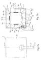
- Fig. 14shows the component side of a printed circuit board of a typical size 11 x 11 cm.
- This printed circuit board 110has in its corner regions four power LEDs D1 to D4, which has a typical power of about 1 to Own 3 watts.
- a rectangular cutout 112is formed in the printed circuit board material in which - thermally decoupled via an air gap - a high-frequency sensor unit 116 formed in a modular manner on a high-frequency circuit board 114 can be suitably contacted via wire bridges 115.
- the high-frequency sensor unit 116is realized in an otherwise known manner as a Doppler unit and forms a movement detection range in a near field, which is between about 10 and about 50 cm from the (not shown in detail) sensor surface or there on the high-frequency circuit board 114 integrated antennas or radiators extends.
- the circuit board 110has, as in particular from the top view of Fig. 13 a plurality of electronic components 120, including, for example, a microcontroller, voltage and current regulators for the LEDs and suitable amplifiers, such peripheral circuits being known as such. These are, in the Fig. 13 shown, concentrated around the cutout 112 in the printed circuit board 110 around, thus centered or centric, thus allowing an edge region R of the printed circuit board with a corresponding edge width without assembly by the components 120 remains. How additionally the comparison with the back of the Fig.
- a cube-shaped configuration of a total of six individual printed circuit boards of the type belonging to the inventionis described below (provided with reference numerals 14a to 14f); These printed circuit boards are embedded in a system of respective surrounding reflector plates (provided with the reference numeral 16), which not only provide for a favorable heat dissipation in the above-described advantageous type, but also limit and channel the respective light emission of the power LEDs and additionally the high-frequency beams of the each centrally provided individual sensor units separate from each other.
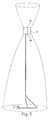
- Fig. 1is a floor lamp 1, comprising an elongated metallic stand 2 and a end held on this luminous body 3 is shown.
- the floor lamp 1comprises a not shown, the luminous body 3 associated external power supply.
- the luminous element 3is contoured in the shape of a cube and arranged pivotable relative to the stator 2 in a defined angular range of 15 °.
- the outer surface of the luminous element 3is formed by a total of six surface segments 4a to 4f, the surface segment provided with the reference 4a forming a front side, the surface segment designated by the reference numeral 4b forming a lower side and the surface segment labeled 4c forming an upper side. Furthermore, two lateral surface segments 4d and 4e (not shown) and a rear surface segment 4f (not shown) are provided, wherein the luminous element 3 is articulated in the region of the rear surface segment 4f on the stator 2. It is essential that all respective adjacent surface segments adjoin one another directly.
- All surface segments 4a to 4fare independently illuminable.
- bulbsare placed in the form of a respective LED array.
- a near field sensorhere a radar sensor, which allows manual, non-contact activation of the light source, such that the arranged behind a surface segment bulbs by a hand movement, preferably a wiping movement in front of the respective surface segment independently of the bulbs adjacent surface segments can be activated and also deactivated again.
- Fig. 2schematically shows the non-contact activation of the front surface segment 4a associated bulbs by a wiping movement by means of the hand 5 of an otherwise not shown operator in the near field in front of the front surface segment 4a.
- the arranged behind the surface segment 4a, that is placed within the luminous body 3 near field sensoris designed and aligned such that it detects a movement in a distance range of about 5 cm with respect to the surface segment 4a and upon detection of a movement activates the associated bulbs or deactivated again.
- Fig. 3shows the luminous element 3 with illuminated, front-side surface segment 4a.
- Essential for the achievable optical effectsis that the flat, square-shaped front surface segment 4a is completely illuminated, but the immediately adjacent, arranged at right angles to the surface segment 4a, flat surface segments 4b to 4e are not illuminated.
- the surface segment 4ais illuminated in such a way that it appears as a homogeneous surface.
- opal glasswas used in the illustrated embodiment.
- transparent glass with an opal glass layermay be provided.
- Fig. 4shows the luminous element 3 with illuminated upper surface segment 4c. All other surface segments 4a, 4b, 4d to 4f are not illuminated.
- Fig. 5shows a lighting condition in which the upper and lower surface segments 4b, 4c facing away from each other are illuminated by activation of the respective associated lighting means. All other surface segments 4a and 4d to 4f are not illuminated, ie the light sources assigned to them are deactivated.
- Fig. 6shows a lighting condition of the luminous element 3, in which all surface segments 4a to 4f are illuminated, that is, all lamps arranged in the luminous element 3 are activated.
- Fig. 7ashows a view of the rear surface segment 4 f of the filament 3.
- the rear surface segment 4 fis penetrated by two metallic rods 6 of the stator 2, which are connected in the area behind the rear surface segment 4 f articulated via fastening means 7 to the filament 3 (see. Fig. 7b ).
- the fastening means 7allow pivoting of the luminous element about a pivot axis 8 running parallel to the lower surface segment 4b.
- a chamber 9a to 9fis arranged in the region behind each surface segment 4a to 4f, each chamber 9a to 9f being bounded on the outside by the associated surface segment 4a to 4f.
- Side walls 10 of the chamber 9a to 9fextend obliquely up to the side edges 11 of the luminous element, on which the surface segments 4a to 4f abut directly against each other and thus prevent illumination of adjacent surface segments.
- a near-field sensor 12a to 12fArranged within each chamber 9a to 9f is a near-field sensor 12a to 12f designed as a radar sensor in the exemplary embodiment shown, which detects movements in the near zone in front of the respective area segment 4a to 4f.
- Each sensor 12a to 12fswitches it upon motion detection associated lighting means 13a to 13f.
- each of a surface segment 4a to 4f associated, each designed as an LED array bulbs 13a to 13f, each with a surface segment 4a to 4f associated near field sensor 12a to 12f manually and non-contact in the near field in front of the respective surface segment 4a to 4f, in particular a wiping actioncan be activated and deactivated manually.
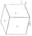
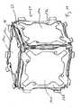
- Fig. 8shows a formed as a cube filament in a view from the outside.
- three surface segments 4a, 4c, 4d of a total of six surface segments 4a to 4fare shown.
- Each surface segmenthas a rectangular, here square peripheral contour, wherein the upper five surface segments (four side surface segments and a lid surface segment) are firmly connected to each other and form a kind of lid or essay, which rests on a lower (carrier) surface segment.
- a stand 2is formed in the embodiment shown of metal and which, as will be explained with reference to the following figures, heat dissipating connected to lighting means.
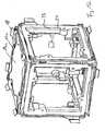
- Fig. 9shows the "inner life" of the filament 3 according to Fig. 8
- the lower (carrier) surface segment 4bwhich carries the lid or attachment formed by the other, not shown surface segments.
- the (support) surface segment 4bis provided with a lateral bevel, which cooperates positively with corresponding bevels of the attachment, so that when the cover or attachment is a cube shape results.
- each chamberis bounded by a printed circuit board 14a to 14f, each parallel to the associated surface segment 4a to 4f arranged circuit board 14a to 14f the respective chamber 9a to 9f associated bulbs 13a to 13f carries.
- a total of four LEDsare provided as lighting means 13a to 13f per printed circuit board 14a to 14f, which are arranged on the corners of an imaginary one Squares are arranged.
- each printed circuit board 14a to 14f arranged at a distance from the associated area segment 4a to 4fcarries a near field sensor 12a to 12f, each near field sensor 12a to 12f each including an antenna 15a to 15f etched into the circuit board 14a to 14f. Further details of the circuit boards 14a to 14f will be apparent from the foregoing description of Fig. 12 to 15 (There, a respective circuit board carries the reference numeral 110).
- each side wall 10is formed by a reflector element 16.
- Fig. 9results, meet three reflector elements 16 at an angle of 120 °.
- two immediately adjacent chambers 9a to 9fare optically separated from each other by a respective side wall 10 formed by a reflector element 16.
- Each chamber 9a to 9fare assigned a total of four circumferentially closed reflector elements 16, wherein each two adjacent chambers 9a to 9f each share a reflector element 16.
- the reflector elements 16thus delimit each chamber 9a to 9f from the respectively adjacent chamber 9a to 9f and ensure that the lighting means 13a to 13f of a chamber 9a to 9f do not illuminate the area segment 4a to 4f of an adjacent chamber 9a to 9f.
- the reflector elements 16have the task to dissipate the heat generated during operation of the lighting means 13a to 13f.
- the reflector elements 16are heat-conductively connected to the light-emitting means 13a to 13f supporting circuit boards 14a to 14f and via printed circuit board frame 17a to 17f, which are formed in the illustrated embodiment of metal.
- the printed circuit board frames 17a to 17fwhich carry the respective printed circuit board 14a to 14f, have lateral, angled lugs 18, with which the reflector elements 16 are soldered.
- Alternative mounting optionsare conceivable.
- each a chamber 9a to 9f limiting reflector elements 16are arranged like a funnel, wherein the funnel in each plane has a rectangular, square, contour here.
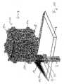
- Fig. 10can be seen by omitting the most reflector elements more details of the structure of a preferred filament 3.
- An inner cube 20comprising the six printed circuit boards 14a to 14f is held on the stator 2 via the adapter element 19.
- the lower (carrier) surface element 4 apenetrated by the stator 2 and sandwiched between the adapter element 19 and a, also penetrated by the stator 2 clamping plate 21 is added.
- the clamping plate 21is screwed by means of screws 22 with the adapter element 19 and thus holds the orthogonal to the stator 2 oriented surface segment 4b, which in turn carries the other, not shown, forming an attachment surface segments.
- Fig. 11the inner cube is 20 according to Fig. 10 shown in isolation.
- the right angles to each other arranged circuit boards 14a to 14fwhich are each fixed to a metallic circuit board frame 17a to 17f, wherein the circuit board frame 17a to 17f are held on a plastic support structure 23.
- the plastic support structure 23is clearly in Fig. 12 to recognize. There it can be seen that the support structure 23 of six identical, each formed as an injection molded part frame parts 24 is formed, which are locked together.
- a control mode controller 25is shown, which is signal-connected to the six near field sensors 12a to 12f (not shown), wherein the control mode controller 25 activates different operating modes, depending on which of the near field sensors 12a to 12f or which near field sensor combinations be activated simultaneously or possibly offset in time.
Landscapes
- Engineering & Computer Science (AREA)
- General Engineering & Computer Science (AREA)
- Physics & Mathematics (AREA)
- Electromagnetism (AREA)
- Computer Networks & Wireless Communication (AREA)
- General Physics & Mathematics (AREA)
- Radar, Positioning & Navigation (AREA)
- Remote Sensing (AREA)
- Arrangement Of Elements, Cooling, Sealing, Or The Like Of Lighting Devices (AREA)
- Non-Portable Lighting Devices Or Systems Thereof (AREA)
- Circuit Arrangement For Electric Light Sources In General (AREA)
- Supplying Of Containers To The Packaging Station (AREA)
Abstract
Description
Translated fromGermanDie vorliegende Erfindung betrifft eine Leiterplatte, welche als Leuchtmittelträger für eine Mehrzahl von Halbleiter-Leuchtmitteln ausgebildet ist und entsprechend Einsatz in zugehörigen Leuchten findet, eine Verwendung einer Leiterplatte sowie einen Leuchtkörper mit mindestens einer Leiterplatte.The present invention relates to a printed circuit board, which is designed as a light source carrier for a plurality of semiconductor lamps and correspondingly finds use in associated lamps, a use of a printed circuit board and a luminous element with at least one printed circuit board.
Insbesondere in der modernen Leuchtentechnologie kommen halbleiterbasierte Leuchtmittel, insbesondere in Form von Leistungs-LEDs (wobei als Leistungs-LED eine LED verstanden werden soll, welche eine elektrische Leistungsaufnahme von mehr als einem Watt aufweist) zunehmend häufig zum Einsatz, wobei neben schnellem Schaltverhalten und dem oftmals gewünschten punktförmigen Lichtquellencharakter die hohe Lichtausbeute als Vorteil ausgenutzt wird; damit verbunden ist eine im Vergleich etwa zu Glühlampen deutlich geringere, bei Leuchten häufig unerwünschte Wärmeentwicklung.In particular, in modern lighting technology semiconductor-based bulbs, especially in the form of power LEDs (which should be understood as a power LED, an LED having an electrical power consumption of more than one watt) are increasingly used, in addition to fast switching behavior and the often desired punctiform light source character the high light output is exploited as an advantage; this is associated with a significantly lower compared to incandescent lamps, in lighting often unwanted heat generation.
Aus diesen Gründen eignen sich LED-Leuchtmittel auch gut für kompakte, integrierte Leuchtenanordnungen, wobei zur Realisierung einer ausreichenden Lichtstärke üblicherweise eine Mehrzahl von Leistungs-LEDs, typischerweise auf einem planen gemeinsamen Träger, etwa einer Leiterplatte, zum Einsatz kommt. Das Vorsehen einer Leiterplatte als Träger bietet dann zusätzlich die Möglichkeit, die zum Ansteuern der Halbleiter-Leuchtmittel benötigte Peripherieelektronik zu integrieren, so dass eine solche Vorgehensweise insbesondere auch unter Aspekten einer kostengünstigen Großserienfertigung bevorzugt ist.For these reasons, LED bulbs are also well suited for compact, integrated lighting arrangements, with a plurality of power LEDs, typically on a common planar support, such as a printed circuit board, is usually used to achieve a sufficient light intensity. The provision of a printed circuit board as a carrier then additionally offers the possibility of integrating the peripheral electronics required for driving the semiconductor light-emitting means, so that such an approach is particularly preferred in view of cost-effective mass production.
Allerdings lässt sich auch bei der Verwendung von (Leistungs-) LEDs eine Integration zu kompakten, häufig auch ästhetisch anspruchsvollen Leuchten nicht beliebig forcieren, da auch Leistungs-LEDs bei voller Aussteuerung nicht unbeträchtliche Wärmeentwicklung zeigen, welche dann oftmals umständlich von der existierenden Leiterplattenanordnung (nach entsprechender, oftmals schwieriger thermischer Ankopplung) abgeführt werden muss.However, even with the use of (power) LEDs, integration into compact, often aesthetically demanding luminaires can not be forced arbitrarily, since power LEDs at full modulation also show not inconsiderable heat development, which is then often cumbersome of the existing printed circuit board arrangement corresponding, often difficult thermal coupling) must be dissipated.
Dieses Problem wird dadurch weiter verschärft, dass häufig derartigen kompakten Leuchten, die eine Vielzahl von (Leistungs-) LEDs integriert aufweisen, Sensoreinheiten zugeordnet sind, welche etwa eine Bewegungssteuerung der Leuchtmittel vornehmen. Offensichtlich ist bereits das thermische Problem bei der Verwendung von (prinzipbedingt wärmeempfindlichen) Infrarot-Sensoren, für welche eine Eigenwärmeentwicklung des jeweils zu steuernden Leuchtmittels beachtliche konstruktive und Konfigurationsprobleme bringt. Auch existiert dieses Problem bei sogenannten Hochfrequenz- bzw. Radarsensoren, welche gegenüber Infrarot-Sensoren den Vorteil aufweisen, etwa zusammen mit dem Leuchtmittel hinter einem Leuchtenschirm, damit von außen unsichtbar, vorgesehen sein zu können, da das hochfrequente Sensorsignal typische Materialien eines solchen Schirms, etwa eine Glasfläche, durchdringt.This problem is exacerbated by the fact that often such compact lights, which have a plurality of (power) LEDs integrated, sensor units are assigned, which make about a movement control of the bulbs. Obviously, the thermal problem in the use of (inherently heat-sensitive) infrared sensors, for which a self-heat development of each to be controlled illuminant brings considerable constructive and configuration problems already. Also, this problem exists in so-called high frequency or radar sensors, which have the advantage over infrared sensors, for example, together with the light source behind a lampshade, thus invisible to be provided from the outside, since the high-frequency sensor signal typical materials of such a screen, about a glass surface, penetrates.
Hier entsteht jedoch das Problem, dass, durch die Abwärme der integriert vorgesehenen Mehrzahl von LED-Leuchtmitteln, typischerweise eine sehr hohe Innentemperatur im Inneren des Leuchtenschirms vorliegt, welche sich nachteilig auf das Detektionsverhalten eines Hochfrequenz-Bewegungssensors auswirkt, insbesondere dessen Hochfrequenzcharakteristik (durch entsprechende thermische Empfindlichkeit der benötigten Hochfrequenz-Bauelemente) kritisch und oft in unberechenbarer Weise beeinflusst. Somit entsteht gerade bei integrierten Leuchteneinheiten, welche möglichst kompakt LED-Leuchtmittel einsetzen und einen zugeordneten Hochfrequenz-Sensor aufweisen, die Herausforderung, eine wirksame Kühlung und Wärmeabfuhr im (Leuchten-) Gehäuseinneren zu ermöglichen, um einen fehlerfreien Leuchten- und Sensorbetrieb der Vorrichtung zu gewährleisten.Here, however, the problem arises that, by the waste heat of the integrally provided plurality of LED bulbs, typically a very high internal temperature is present in the interior of the lampshade, which adversely affects the detection behavior of a high-frequency motion sensor, in particular its high-frequency characteristic (by appropriate thermal Sensitivity of the required high-frequency components) critically and often unpredictably influenced. Thus arises just in integrated lighting units, which use LED bulbs as compact as possible and having an associated high-frequency sensor, the challenge to enable effective cooling and heat dissipation in (housing) inside the housing to ensure a faultless operation of the lamp and sensor device ,
Aufgabe der vorliegenden Erfindung ist es daher, eine gattungsgemäße, als Leuchtmittelträger für eine Mehrzahl von Halbleiter-Leuchtmitteln ausgebildete Leiterplatte so zu verbessern, dass dieser einerseits eine Mehrzahl von Halbleiter-Leuchtmitteln, insbesondere Leistungs-LEDs, tragen und wirksam ansteuern kann, gleichzeitig für eine in kompakter Weise an oder auf der Leiterplatte vorzusehende Hochfrequenz-Sensoreinheit thermische Voraussetzungen (durch entsprechende wirksame Wärmeabfuhr von den LED-Leuchtmitteln) zu schaffen, dass ein störungsfreier Sensorbetrieb gewährleistet ist. Ferner ist eine Verwendung einer solchen Leiterplatte zu schaffen sowie ein Leuchtkörper, der mindestens eine solche Leiterplatte aufweist.The object of the present invention is therefore to improve a generic printed circuit board designed as a light source carrier for a plurality of semiconductor light-emitting devices in such a way that, on the one hand, it can carry and effectively drive a plurality of semiconductor light-emitting means, in particular power LEDs, simultaneously for one in a compact manner to be provided on or on the circuit board high-frequency sensor unit thermal conditions (by appropriate effective heat dissipation from the LED bulbs) to create that a trouble-free sensor operation is guaranteed. Furthermore, to provide a use of such a printed circuit board and a luminous body having at least one such circuit board.
Die Aufgabe wird durch die Leiterplatte mit den Merkmalen des Hauptanspruchs, die Verwendung nach dem Anspruch 13 sowie der Leuchtkörper nach dem Anspruch 14 gelöst; vorteilhafte Weiterbildungen der Erfindung sind in den Unteransprüchen beschrieben. So wird im Rahmen der Erfindung auch Schutz beansprucht für eine Verwendung der Leiterplatte als Leuchtmodul mit einer Mehrzahl von darauf vorgesehenen Halbleiter-Leuchtmitteln sowie einer darauf oder daran vorgesehenen modulartig ausgebildeten Hochfrequenz-Sensoreinheit, so dass mit der vorliegenden Erfindung die Voraussetzungen für kompakte, gleichwohl thermisch optimierte Leuchten und Leuchteneinheiten geschaffen sind.The object is achieved by the circuit board having the features of the main claim, the use according to claim 13 and the luminous element according to claim 14; advantageous developments of the invention are described in the subclaims. Thus, within the scope of the invention, protection is also claimed for use of the printed circuit board as a lighting module having a plurality of semiconductor lamps provided thereon and a module-like high-frequency sensor unit provided thereon or thereto, so that with the present invention the prerequisites for compact, nevertheless thermal optimized luminaires and lighting units are created.
Damit eignet sich die vorliegende Erfindung insbesondere zur Realisierung der in der deutschen Gebrauchsmusteranmeldung
In erfindungsgemäß vorteilhafter Weise ist die Leiterplatte -- bevorzugt mit zwei metallisierten Leiterplattenoberflächen zum Ausbilden von jeweiligen Leiterplattenflächen bzw. Leiterbahnen -- vieleckig, bevorzugt rechteckig, weiter bevorzugt quadratisch, so ausgebildet, dass in den Eckbereichen etwa eines Rechtecks oder Quadrats Leistungs-Halbleiterleuchtmittel vorgesehen sein können. Um insoweit erfindungsgemäß eine optimierte Wärmeabfuhr von den Leuchtmitteln zu ermöglichen, werden Bereiche der metallisch - kaschierten Oberfläche der Leiterplatte als metallisierte Flächenabschnitte und Kühlflächen im Sinne der Erfindung benutzt, um die Betriebswärme der Halbleiter-Leuchtmittel abzuführen, wobei geeignete Wärmeleitelemente, etwa weiterbildungsgemäß vorgesehene flächige Reflektorelemente (Reflektorbleche) an oder auf diese metallisierten Flächenabschnitte (ggf. unter Zwischenschaltung von mechanischen Komponenten oder geeigneter Wärmeleitpaste oder dergleichen) gebracht werden können.In an advantageous manner according to the invention, the printed circuit board is preferably polygonal, preferably rectangular, more preferably square, preferably with two metallized printed circuit board surfaces for forming respective printed circuit board surfaces or conductor tracks, such that power semiconductor illuminants are provided in the corner regions of, for example, a rectangle or square can. In order to allow optimized heat removal from the light sources in this respect, regions of the metallically laminated surface of the printed circuit board are used as metallized surface sections and cooling surfaces in the sense of the invention in order to dissipate the operating heat of the semiconductor light-emitting means, with suitable heat-conducting elements, for example planar reflector elements provided for further development (Reflector sheets) on or on these metallized surface portions (possibly with the interposition of mechanical components or suitable thermal grease or the like) can be brought.
Insbesondere im Fall einer rechteckigen bzw. quadratischen Leiterplatte sind diese metallisierten Flächenabschnitte zur Wärmeabfuhr randseitig vorgesehen, weiter bevorzugt randseitig umlaufend, so dass ein zur Wärmeabfuhr maximierter Bereich der Leiterplatte für diese thermische Aufgabe zur Verfügung steht.In particular, in the case of a rectangular or square printed circuit board, these metallized surface portions are provided for heat removal edge, more preferably peripherally circumferentially, so that a maximized for heat dissipation area of the circuit board for this thermal task is available.
Dabei ist erfindungsgemäß vorgesehen, mittig bzw. zentrisch auf bzw. in der Leiterplatte einen Flächenbereich bzw. Durchbruch für ein als Modul vorhandenes, bevorzugt auf einer eigenen, gegenüber der Leiterplatte verkleinerten Sensor-Leiterplatte aufgebaute Sensoreinheit vorzusehen, so dass bereits räumlich innerhalb der Leiterplattengeometrie ein Abstand von (in etwa den Ecken der Leiterplatte sitzenden) Halbleiter-Leuchtmitteln zum mittigen Sensor maximiert ist.It is provided according to the invention, centrally or centrally on or in the circuit board to provide a surface area or breakthrough for a present as a module, preferably on its own, compared to the PCB scaled sensor PCB sensor unit, so that already spatially within the PCB geometry Distance from (about the corners of the circuit board sitting) semiconductor lamps is maximized to the central sensor.
Geometrisch lässt sich zudem eine wirksame Fläche der erfindungsgemäß als Kühlfläche und Kontaktfläche für Wärmeleitelemente (etwa Reflektorbleche) dienenden metallisierten Flächenabschnitte dadurch weiter optimieren, dass die zusätzlich zu den Halbleiter-Leuchtmitteln vorgesehenen und deren Peripherieelektronik ausbildenden elektronischen Bauelemente mit ihrer Anordnung auf der Leiterplatte im Mittelbereich, ideal um die Sensoreinheit bzw. den zugehörigen Flächenbereich bzw. Durchbruch herum, angeordnet sind, so dass ein möglichst großer (metallisierter) Leiterplattenbereich zum Realisieren der thermischen Kühlfläche im Randbereich verbleibt. So ist es etwa weiterbildungsgemäß bevorzugt, eine wirksame Streifenbreite eines von derartigen Bauelementen freien, damit ununterbrochenen und durchgehenden Leiterbahnenbereichs, zumindest entlang eines Randes der Leiterplatte, bevorzugt entlang mehrerer Ränder oder gar umlaufend, so auszubilden, dass die Breite mindestens 10% der zugehörigen Leiterplattenerstreckung, weiter bevorzugt mindestens 15%, noch weiter bevorzugt mindestens 20% dieser Erstreckung beträgt. Entsprechend entsteht die Möglichkeit für eine große wirksame metallisierte Fläche zur Wärmeabfuhr.In addition, an effective area of the metalized surface sections serving as cooling surface and contact surface for heat-conducting elements (such as reflector sheets) can be geometrically further optimized by the fact that the electronic components which are provided in addition to the semiconductor lamps and whose peripheral electronics form electronic components with their arrangement on the printed circuit board in the middle region, are ideally around the sensor unit or the associated surface area or breakthrough around, are arranged so that the largest possible (metallized) PCB area for realizing the thermal cooling surface remains in the edge region. For example, according to further developments, it is preferable to form an effective strip width of a continuous strip region free of such components, at least along one edge of the printed circuit board, preferably along several edges or even circumferentially, such that the width is at least 10% of the associated printed circuit board extension. more preferably at least 15%, more preferably at least 20% of this extension. Accordingly, the possibility arises for a large effective metallized surface for heat dissipation.
Wie vorstehend dargelegt und nachfolgend in der Figurenbeschreibung zur Erfindung beschrieben, bieten die metallisierten Flächenabschnitte gemäß derAs set forth above and described below in the description of the description of the invention, the metallized surface portions according to the
Erfindung die Möglichkeit zum Kontaktieren mit Wärmeleitelementen, um für eine weitere Wärmeabfuhr zu sorgen. Weiterbildungsgemäß im Rahmen der Erfindung ist daher vorgesehen, flächige Reflektorelemente wärmeleitend zu kontaktieren, mit einem Vorteil in mehrerer Hinsicht: Einerseits kann, etwa durch geeignete metallische Ausgestaltung dieser flächigen Reflektorelemente, eine wirksame Wärmeabfuhr bewirkt werden, zusätzlich wirken diese Reflektorelemente als Blende bzw. Reflektor für die auf der Leiterplatte sitzenden Leuchtmittel, so dass bei geeigneter Ausgestaltung der Reflektorelemente eine lichttechnische bzw. beleuchtungsmäßige Optimierung erfolgen kann (und als weiterer Vorteil können diese Reflektorelemente zudem so realisiert sein, dass sie eine wirksame hochfrequenzmäßige Sperre bzw. Entkopplung für das Sensorsignal erreichen, wichtig insbesondere für den Fall, dass eine Mehrzahl von Leiterplatten der vorliegend erfindungsgemäßen Art einander benachbart vorgesehen sind und jeweilige Hochfrequenz-Sensoreinheiten ansonsten eine gegenseitige Störung bewirken würden; mit anderen Worten, die Reflektorelemente ermöglichen zusätzlich eine Ausrichtung bzw. Fokussierung eines Hochfrequenz-Erfassungsbereichs der jeweiligen Sensoreinheit).Invention the possibility of contacting with heat conducting elements to provide for further heat dissipation. According to the invention within the scope of the invention is therefore intended to contact flat reflector elements thermally conductive, with an advantage in several respects: On the one hand, such as by suitable metallic design of these flat reflector elements, an effective heat dissipation can be effected, in addition these reflector elements act as a panel or reflector for the light source sitting on the circuit board, so that with a suitable design of the reflector elements a lighting or optimization optimization can take place (and as a further advantage, these reflector elements can also be realized so that they achieve an effective high-frequency barrier or decoupling for the sensor signal, important in particular for the case that a plurality of printed circuit boards of the present invention type are provided adjacent to each other and respective high-frequency sensor units would otherwise cause a mutual interference; In other words, the reflector elements additionally allow alignment or focusing of a high-frequency detection region of the respective sensor unit).
Insbesondere in dem Fall, dass -- bei bevorzugt viereckiger bzw. quadratischer Leiterplatte -- ein derartiges flächiges Reflektorelement an jeder Randseite vorgesehen ist, entsteht so ein gehäuseartiges Modul, welches zudem weiterbildungsgemäß dadurch verschlossen werden kann, dass, zur Leiterplatte parallel ausgerichtet, der Innenraum mit einer geeignet für die Lichtemission der Halbleiter-Leuchtmittel sowie das Hochfrequenz-Sensorsignal durchlässigen Scheibe verschlossen wird. Wie vorstehend beschrieben, bieten die erfindungsgemäßen Maßnahmen die Möglichkeit, die Temperatur im Inneren einer solchen Einheit geeignet abzusenken, insbesondere wenn mindestens einem der Reflektorelemente zusätzlich weitere Mittel zur Wärmeableitung, etwa in ein umgebendes Gehäuse, einen umgebenden Ständer oder dergleichen, zugeordnet sind.In particular, in the case that - in preferably square or square circuit board - such a planar reflector element is provided on each edge side, so creates a box-like module, which can also be closed by further education, characterized in that, aligned parallel to the circuit board, the interior is closed with a suitable for the light emission of the semiconductor light source and the high-frequency sensor signal transmissive disk. As described above, the measures according to the invention offer the possibility of lowering the temperature in the interior of such a unit, in particular if at least one of the reflector elements is additionally associated with further means for dissipating heat, for example into a surrounding housing, a surrounding stand or the like.
Besonders bevorzugt im Rahmen der Erfindung ist die Leiterplatte Teil eines Leuchtkörpers mit mindestens zwei aneinander angrenzenden, ausleuchtbarenParticularly preferred in the context of the invention, the circuit board is part of a luminous element with at least two adjacent, illuminable
Flächensegmenten gelöst, denen jeweils mindestens ein Leuchtmittel zugeordnet und hinter dem jeweiligen Flächensegment angeordnet ist, wobei die mindestens zwei Leuchtmittel unabhängig voneinander manuell und berührungslos im Nahfeld vor dem jeweiligen Flächensegment aktivierbar sind, so dass die mindestens zwei Flächensegmente unabhängig voneinander ausleuchtbar sind. Diese Weiterbildung bzw. Verwendung der Erfindung kombiniert ein ansprechendes Bedienkonzept auf geschickte Weise mit einem beeindruckenden Ausleuchtkonzept dadurch, dass ein erstes und mindestens ein zweites Flächensegment, insbesondere Oberflächensegmente, vorgesehen werden, die unmittelbar aneinander angrenzen, wobei die Flächensegmente unabhängig voneinander ausleuchtbar, d.h. die den Flächensegmenten zugeordneten Leuchtmittel unabhängig voneinander aktivierbar sind, so dass die Flächensegmente gemeinsam oder einzeln ausgeleuchtet werden können, vorzugsweise derart, dass die bei einer gemeinsamen Beleuchtung beider Flächensegmente keine Grenzfläche zwischen den Flächensegmenten sichtbar ist und bei voneinander separater Ausleuchtung eine scharfe Grenze zwischen dem ausgeleuchteten Flächensegment und dem unausgeleuchteten Flächensegment erkennbar ist. Wesentlich zur Erzielung des gewünschten Effektes ist das beanspruchte Bedienkonzept, nach dem die dem jeweiligen Flächensegment zugeordneten Leuchtmittel manuell und berührungslos, vorzugsweise durch eine Wischbewegung vor dem jeweiligen Flächensegment, aktivierbar sind. Anders ausgedrückt können die dem ersten Flächensegment zugeordneten und hinter diesem angeordneten Leuchtmittel berührungslos durch Anwesenheit oder Bewegung im Nahfeld, d.h. innerhalb eines Abstandes vom Flächensegment von typischerweise weniger als 10 cm, vorzugsweise von weniger als 5 cm, aktiviert werden und die dem zweiten Flächensegment zugeordneten Leuchtmittel durch eine Anwesenheit oder Bewegung im Nahfeld vor dem zweiten Flächensegment. Durch die Kombination dieses Bedienkonzeptes mit aneinander angrenzenden, vorzugsweise vollständig, ausleuchtbaren Flächensegmenten entsteht ein völlig neuer, überraschend visueller Effekt beim Betrachter bzw. Bediener. Bevorzugt sind die Leuchtmittel nicht nur unabhängig voneinander manuell und berührungslos im Nahfeld vor dem jeweiligen Flächensegment aktivierbar, sondern auch auf diese Weise, d.h. durch Anwesenheits- oder Bewegungsdetektion, wieder deaktivierbar.Solved surface segments, each associated with at least one light source and is arranged behind the respective surface segment, the at least two bulbs are independently activated manually and non-contact in the near field in front of the respective surface segment, so that the at least two surface segments are independently illuminable. This development or use of the invention skillfully combines an appealing operating concept with an impressive illumination concept in that a first and at least one second surface segment, in particular surface segments, are provided, which adjoin one another directly, wherein the surface segments can be illuminated independently of each other, ie the Lamps associated with surface segments can be activated independently, so that the surface segments can be illuminated together or individually, preferably such that at a common illumination of both surface segments no interface between the surface segments is visible and with separate illumination a sharp boundary between the illuminated surface segment and the unausgeleuchteten surface segment is recognizable. Essential to achieve the desired effect is the claimed operating concept, according to which the respective area segment associated bulbs manually and non-contact, preferably by a wiping movement in front of the respective surface segment, can be activated. In other words, the illuminants associated with the first surface segment and arranged behind them can be activated contactlessly by presence or movement in the near field, ie within a distance of the surface segment of typically less than 10 cm, preferably less than 5 cm, and the illuminant associated with the second surface segment by a presence or movement in the near field in front of the second surface segment. The combination of this operating concept with adjoining, preferably complete, illuminable surface segments creates a completely new, surprisingly visual effect on the viewer or operator. Preferably, the lighting means are not only independently and manually activatable without contact in the near field in front of the respective area segment, but also in this way, ie by presence or movement detection, again deactivated.
Grundsätzlich ist es möglich, die unmittelbar aneinander angrenzenden Flächensegmente aus zwei miteinander verbundenen Bauteilen auszubilden. Besonders bevorzugt ist es jedoch, wenn die Flächensegmente nahtlos ineinander übergehen, d.h. einstückig, vorzugsweise aus einem Guss ausgebildet sind.In principle, it is possible to form the immediately adjacent surface segments of two interconnected components. However, it is particularly preferred if the surface segments merge seamlessly, i. in one piece, preferably formed from a cast.
Ganz besonders bevorzugt ist jedem ausleuchtbaren Flächensegment jeweils ein Nahfeldsensor als Hochfrequenzsensor, vorzugsweise Radarsensor, zugeordnet, der mit dem den jeweiligen Flächensegment zugeordneten Leuchtmitteln wirkverbunden ist, derart, dass wenn von dem Nahfeldsensor eine Bewegung oder eine Anwesenheit vor dem jeweiligen Flächensegment detektiert wird die Leuchtmittel dauerhaft, oder bis zur Deaktivierung oder für eine definierte Zeitspanne aktiviert werden.Most preferably, each illuminable surface segment is associated with a near field sensor as a high-frequency sensor, preferably a radar sensor, which is operatively connected to the light source associated with the respective surface segment, such that when the movement or presence is detected by the near field sensor before the respective surface segment, the light source is permanently illuminated , or are activated until deactivation or for a defined period of time.
Besonders zweckmäßig ist eine Ausführungsform des Leuchtkörpers, bei der die Nahfeldsensoren, insbesondere gemeinsam mit den jeweiligen Leuchtmitteln hinter den Flächensegmenten angeordnet sind. Anders ausgedrückt, befindet sich bevorzugt hinter jedem ausleuchtbaren Flächensegment ein Nahfeldsensor und mindestens ein Leuchtmittel, vorzugsweise eine Gruppe von LEDs.Particularly expedient is an embodiment of the luminous element, in which the near-field sensors, in particular together with the respective luminous means, are arranged behind the surface segments. In other words, a near field sensor and at least one light source, preferably a group of LEDs, is preferably located behind each illuminable area segment.
Die Flächensegmente bzw. die Leuchtkörperoberfläche ist bevorzugt derart ausgebildet, dass die hinter den Flächensegmenten angeordneten Leuchtmittel die Flächensegmente durchleuchten können. Besonders bevorzugt sind die Flächensegmente hierzu aus Kunststoff oder Glas ausgebildet, wobei besonders gute optische Effekte dadurch erreicht werden können, dass der Kunststoff oder das Glas opak eingefärbt sind. Bevorzugt sind die Flächensegmente aus nicht durchsichtigem, jedoch lichtdurchlässigem Material, insbesondere Kunststoff oder Glas ausgebildet. Ganz besonders bevorzugt sind die ausleuchtbaren Flächensegmente aus Kryolithglas (Opalglas) gefertigt. Hierbei handelt es sich um getrübtes, milch-weiß erscheinendes Glas. Auch ist es möglich, transparentes Material mit einem nicht durchsichtigen, jedoch lichtdurchlässigen Material zu beschichten. Besonders beeindruckende optische Effekte können dadurch erzielt werden, dass die mindestens zwei Flächensegmente winklig zueinander angeordnet werden, um hierdurch, obwohl die Flächensegmente unmittelbar aneinander angrenzen eine scharfe optische Trennung bei separater Ausleuchtung zu erzielen. Besonders beeindruckend sind die erzielbaren optischen Effekte bei einer rechtwinkligen Anordnung der mindestens zwei ausleuchtbaren Flächensegmente. Dabei ist es noch weiter bevorzugt, wenn der Leuchtkörper insgesamt als Quader ausgeformt ist, vorzugsweise als Kubus, also mit insgesamt gleich langen Seitenkanten. Mit Vorteil beträgt die Seitenkantenlänge 10 bis 15 cm, noch weiter bevorzugt 11 cm. Noch weiter bevorzugt ist es dabei, wenn sämtliche resultierenden sechs Flächensegmente unabhängig voneinander ausleuchtbar sind, d.h. dass hinter jedem der sechs Flächensegmente ein Nahfeldsensor und mindestens ein Leuchtmittel angeordnet ist. Auch ist es denkbar, dass lediglich fünf Flächensegmente unabhängig voneinander ausleuchtbar sind, insbesondere dann, wenn eines der sechs Flächensegmente zu einer Decke, zu einer Tragfläche oder zu einer Wand ausgerichtet ist.The surface segments or the luminous body surface is preferably designed such that the light sources arranged behind the surface segments can illuminate the surface segments. For this purpose, the surface segments are particularly preferably made of plastic or glass, wherein particularly good optical effects can be achieved in that the plastic or the glass is colored opaque. Preferably, the surface segments of non-transparent, but translucent material, in particular plastic or glass are formed. Most preferably, the illuminable surface segments made of cryolite glass (opal glass) are made. This is cloudy, milk-white appearing glass. It is also possible transparent material with a non-transparent, but translucent material to coat. Particularly impressive optical effects can be achieved by arranging the at least two surface segments at an angle to one another, in order thereby to achieve a sharp optical separation with separate illumination, even though the surface segments adjoin one another directly. Particularly impressive are the achievable optical effects in a rectangular arrangement of at least two illuminable surface segments. In this case, it is even more preferable if the luminous element as a whole is shaped as a cuboid, preferably as a cube, that is to say with generally equal side edges. Advantageously, the side edge length is 10 to 15 cm, more preferably 11 cm. In this case, it is even more preferable if all the resulting six surface segments can be illuminated independently of one another, ie that a near field sensor and at least one light source are arranged behind each of the six surface segments. It is also conceivable that only five surface segments can be illuminated independently of one another, in particular if one of the six surface segments is aligned with a ceiling, an airfoil or a wall.
Die erzielbaren optischen Effekte können dadurch weiter verbessert werden, dass die Flächensegmente als ebene, vorzugsweise, zumindest näherungsweise, zweidimensionale, d.h. plattenförmige, Flächensegmente ausgestaltet sind.The achievable optical effects can be further improved by making the surface segments as planar, preferably, at least approximately, two-dimensional, i. plate-shaped, surface segments are configured.
Im Hinblick auf die konkrete Anordnung der Leuchtmittel gibt es unterschiedliche Möglichkeiten. Ganz besonders bevorzugt ist es eine Ausführungsform, bei der die Leuchtmittel in einem gemeinsamen, außen von den Flächensegmenten begrenzten Raum angeordnet sind und die Leuchtmittel derart ausgerichtet und angeordnet sind, dass sie jeweils nur das ihnen zugeordnete Flächensegment ausleuchten. Bei einer derartigen Ausführungsform ist es weiter bevorzugt, wenn die Flächensegmente winklig, insbesondere rechtwinklig zueinander angeordnet sind, um eine optische Trennung bei den unmittelbar aneinander angrenzenden Flächensegmenten zu erzielen.With regard to the specific arrangement of the bulbs, there are different possibilities. Very particular preference is given to an embodiment in which the lighting means are arranged in a common space bounded on the outside by the surface segments, and the lighting means are aligned and arranged in such a way that they illuminate only the area segment assigned to them. In such an embodiment, it is further preferred if the surface segments are arranged at an angle, in particular at right angles to one another, in order to achieve an optical separation in the directly adjoining surface segments.
Bei einer alternativen Ausführungsvariante des Leuchtkörpers sind die den unterschiedlichen Flächensegmenten zugeordneten Leuchtmittel nicht in einem gemeinsamen Raum angeordnet, sondern jedem Flächensegment ist im Innern des Leuchtkörpers eine Kammer zugeordnet, in der die dem Flächensegment zugeordneten Leuchtmittel, bevorzugt zusammen mit einem Nahfeldsensor angeordnet sind, wobei die Kammerwände eine Ausleuchtung benachbarter Flächensegmente mittels der einem Flächensegment zugeordneten Leuchtmittel sicher verhindern. Bevorzugt sind die Kammerwände von außerhalb des Leuchtkörpers nicht zu erkennen.In an alternative embodiment of the luminous element, the illuminants associated with the different surface segments are not in one arranged common space, but each surface segment is assigned a chamber in the interior of the luminous element, in which the surface segment associated bulbs are preferably arranged together with a near field sensor, the chamber walls reliably prevent illumination of adjacent surface segments by means of a surface segment associated with light source. Preferably, the chamber walls are not visible from outside the luminous body.
Wie zuvor erläutert, ist bei einer bevorzugten Ausführungsvariante des Leuchtkörpers vorgesehen, dass die Flächensegmente eine ebene, d.h. im Wesentlichen zweidimensionale Oberfläche aufweisen. Gemäß einer alternativen, ebenfalls bevorzugten Ausführungsform ist vorgesehen, dass die Flächensegmente dreidimensional ausgeformt sind. Hierdurch kann ein nahezu beliebig ausgeformter Leuchtkörper in unterschiedliche, aneinander angrenzende Flächensegmente unterteilt werden, die unabhängig voneinander ausleuchtbar sind.As explained above, it is provided in a preferred embodiment of the luminous element that the surface segments have a plane, i. have substantially two-dimensional surface. According to an alternative, likewise preferred embodiment, it is provided that the surface segments are formed in three dimensions. In this way, a nearly arbitrarily shaped luminous body can be subdivided into different adjoining surface segments, which can be illuminated independently of one another.
Besonders vorteilhaft ist eine Ausführungsvariante des Leuchtkörpers, bei der die Außenoberfläche des Leuchtkörpers ausschließlich aus ausleuchtbaren Flächensegmenten ausgebildet ist, wobei zumindest jeweils zwei benachbarte Flächensegmente unmittelbar aneinander angrenzen. Bei einer alternativen Ausführungsform sind mindestens zwei unabhängig voneinander ausleuchtbare Flächensegmente mit mindestens einem nicht ausleuchtbaren Flächensegment kombiniert.Particularly advantageous is an alternative embodiment of the luminous element, in which the outer surface of the luminous element is formed exclusively by illuminable surface segments, wherein at least in each case two adjacent surface segments adjoin one another directly. In an alternative embodiment, at least two independently illuminable surface segments are combined with at least one non-illuminable surface segment.
Der Leuchtkörper kann auf vielfältige Weise im Raum angeordnet werden. So ist es denkbar, den Leuchtkörper an einer Wand festzulegen, wobei es dabei besonders bevorzugt ist, wenn die Befestigungsmittel zum Festlegen des Leuchtkörpers an der Wand an einer Seitenkante oder an einem Eck des Leuchtkörpers angeordnet sind und nicht mittig an einem Flächensegment, wobei auch eine derartige Ausführungsform realisierbar ist. Zusätzlich oder alternativ können Befestigungsmittel zum Festlegen des Leuchtkörpers an einer Decke, insbesondere einer Raumdecke oder auf Ständer, insbesondere einem säulenförmigen Ständer vorgesehen werden. Wenn dem Leuchtkörper ein Ständer, insbesondere ein säulenförmiger Ständer, zugeordnet ist, kann bei Bedarf auch auf Befestigungsmittel verzichtet und der Leuchtkörper auf den Ständer flächig abgestellt werden.The luminous element can be arranged in various ways in the room. Thus, it is conceivable to fix the luminous body on a wall, wherein it is particularly preferred if the fastening means for fixing the filament to the wall at a side edge or at a corner of the filament are arranged and not centrally on a surface segment, wherein a Such embodiment is feasible. Additionally or alternatively, fastening means for fixing the filament to a ceiling, in particular a ceiling or on stand, in particular a columnar stand can be provided. When the lamp is a Stand, in particular a columnar stand, is assigned, if necessary, can also be dispensed with fastening means and the luminous body are placed flat on the stand.
Ganz besonders bevorzugt ist eine Ausführungsvariante des Leuchtkörpers, bei der mehrere der Kammern, vorzugsweise jede Kammer, vorzugsweise auf der von dem Flächensegment abgewandten Seite von jeweils einer Leiterplatte begrenzt sind/ist, die die jeweiligen Leuchtmittel und den zugehörigen Nahfeldsensor trägt. Dabei ist es besonders bevorzugt, wenn die Leiterplatte, zumindest näherungsweise, parallel zu dem zugehörigen Flächensegment angeordnet ist, so dass das Flächensegment die Kammer auf der Vorderseite begrenzt. Besonders zweckmäßig ist es, wenn pro Leiterplatte mehrere, insbesondere vier, LEDs vorgesehen sind, wobei es noch weiter bevorzugt ist, wenn die LEDs auf den Enden eines gedachten Rechtecks angeordnet sind. Im Hinblick auf die konkrete Ausbildung der zum jeweiligen Nahfeldsensor gehörenden Antenne gibt es unterschiedliche Möglichkeiten. Besonders bevorzugt ist es, wenn es sich bei der Antenne um eine in die Leiterplatte geätzte Antenne handelt.Very particular preference is given to an alternative embodiment of the luminous element in which a plurality of the chambers, preferably each chamber, are preferably delimited on the side facing away from the surface segment by in each case one printed circuit board which carries the respective luminous means and the associated near-field sensor. It is particularly preferred if the circuit board, at least approximately, is arranged parallel to the associated surface segment, so that the surface segment bounds the chamber on the front side. It is particularly expedient if several, in particular four, LEDs are provided per printed circuit board, wherein it is even more preferable if the LEDs are arranged on the ends of an imaginary rectangle. With regard to the specific design of the antenna belonging to the respective near-field sensor, there are different possibilities. It is particularly preferred if the antenna is an antenna etched into the printed circuit board.
Ganz besonders bevorzugt ist es, wenn ein aus acht Leiterplatten gebildeter Kubus vorgesehen ist, der zentrisch im Leuchtkörper angeordnet ist. Besonders bevorzugt werden die Leiterplatten hierzu von einer, beispielsweise als Kunststoffspritzgussteil ausgebildeten Tragkonstruktion getragen, die sich noch weiter bevorzugt innerhalb des von den Leiterplatten gebildeten Kubus befindet.It is particularly preferred if a cube formed from eight printed circuit boards is provided, which is arranged centrally in the luminous element. For this purpose, the printed circuit boards are particularly preferably supported by a support structure designed, for example, as a plastic injection-molded part, which is even more preferably located inside the cube formed by the printed circuit boards.
Wie zuvor erläutert, ist es bevorzugt, wenn die Kammern jeweils von einem Flächensegment und einer Leiterplatte auf Vorder- bzw. Rückseite begrenzt sind. Bevorzugt sind die Kammern in einem Bereich zwischen Flächensegment und Leiterplatte von Reflektorelementen begrenzt, wobei die Reflektorelemente derart angeordnet sind, dass diese jeweils zwei benachbarte Kammern (optisch) voneinander separieren, vorzugsweise derart, dass die Leuchtmittel einer ersten Kammer nicht das Flächensegment einer zweiten, benachbarten Kammer beleuchten können. Besonders bevorzugt ist es, wenn die Reflektorelemente eine Doppelfunktion haben, also nicht nur für eine optische Separierung der Kammern Sorge tragen, sondern zudem als Wärmebrücke bzw. Wärmeleitmittel dienen, um die im Betrieb der Leuchtmittel entstehende Wärme abzuführen. Zu diesem Zweck ist es bevorzugt, wenn die Reflektorelemente mit den Leiterplatten wärmeleitend verbunden sind - bevorzugt ist jedes Reflektorelement wärmeleitend mit mindestens einer zugeordneten Leiterplatte verbunden, insbesondere dadurch, dass das Reflektorelement mit einem, insbesondere metallischen, Leiterplattenrahmen verbunden ist. Im Hinblick auf die konkrete Ausbildung bzw. Materialwahl zur Herstellung der Reflektorelemente gibt es unterschiedliche Möglichkeiten. Besonders bevorzugt ist es im Hinblick auf eine gute Wärmeleitfähigkeit, die Reflektorelemente als Metallbleche auszubilden. Alternativ ist es denkbar, die Reflektorelemente als Kunststoffspritzgussteile auszubilden, wobei es in diesem Fall bevorzugt ist, einen wärmeleitenden Kunststoff einzusetzen oder den Kunststoff mit wärmeleitenden Partikeln, insbesondere Metallpartikeln, zu versetzen.As previously explained, it is preferred if the chambers are each delimited by a surface segment and a printed circuit board on the front or rear side. Preferably, the chambers are delimited by reflector elements in a region between the surface segment and the printed circuit board, wherein the reflector elements are arranged such that they respectively separate (optically) two adjacent chambers, preferably such that the luminous means of a first chamber do not cover the surface segment of a second, adjacent one Can illuminate chamber. It is particularly preferred if the reflector elements have a double function, that is not only for optical separation take care of the chambers, but also serve as a thermal bridge or heat conduction to dissipate the heat generated during operation of the lamps. For this purpose, it is preferred if the reflector elements are connected to the printed circuit boards heat-conducting - preferably each reflector element is thermally conductively connected to at least one associated circuit board, in particular in that the reflector element is connected to a, in particular metallic, circuit board frame. With regard to the concrete training or choice of material for the production of the reflector elements, there are different possibilities. With regard to a good thermal conductivity, it is particularly preferred to design the reflector elements as metal sheets. Alternatively, it is conceivable to design the reflector elements as plastic injection-molded parts, it being preferred in this case to use a thermally conductive plastic or to offset the plastic with thermally conductive particles, in particular metal particles.
Im Hinblick auf die Befestigung der Reflektorelemente an den Leiterplatten bzw. den Leiterplattenrahmen gibt es unterschiedliche Möglichkeiten. Denkbar ist es, das Reflektorelement mit Haltelaschen des Leiterplattenrahmens zu verlöten. Steck- bzw. Clipkonstruktionen sind ebenfalls alternativ realisierbar.With regard to the attachment of the reflector elements to the circuit boards or the circuit board frame, there are different possibilities. It is conceivable to solder the reflector element with retaining tabs of the circuit board frame. Plug or clip constructions are also possible as an alternative.
Besonders bevorzugt ist eine Ausführungsvariante, bei der mindestens ein, vorzugsweise ausschließlich ein, Reflektorelement mit einem, insbesondere von mindestens einem Stab, vorzugsweise von zwei Stäben gebildeten, Leuchtkörperfuß (Ständer) verbunden ist, der noch weiter bevorzugt aus Metall ausgebildet ist, um die Wärme über das Reflektorelement und ggf. ein Adapterstück an den Fuß (Ständer) und über diesen an die Umgebung ableiten zu können. Der Fuß (Ständer) dient bevorzugt als Wärmesenke.Particularly preferred is a variant in which at least one, preferably only one, reflector element with a, in particular of at least one rod, preferably formed by two rods, Leuchtkörperfuß (stand) is connected, which is even more preferably formed of metal to the heat via the reflector element and possibly an adapter piece to the foot (stand) and to be able to derive via this to the environment. The foot (stand) is preferably used as a heat sink.
Besonders zweckmäßig ist eine Ausführungsvariante des Leuchtkörpers, bei der die Leuchtmittel und die Nahfeldsensoren, welche bevorzugt sämtliche auf Leiterplatten angeordnet sind, im ausgeschalteten Zustand der Leuchtmittel nicht sichtbar sind. Bevorzugt sind die Flächensegmente hierzu milchglasartig getrübt.Particularly useful is a variant of the filament, in which the bulbs and the near field sensors, which are preferably all arranged on printed circuit boards, are not visible in the off state of the bulbs. Preferably, the surface segments are clouded like this for a glassy glass.
In Weiterbildung der Erfindung ist mit Vorteil vorgesehen, dass mindestens zwei unterschiedlichen Flächensegmenten zugeordnete Nahfeldsensoren, insbesondere sämtlichen Nahfeldsensoren, ein gemeinsamer Steuermoduscontroller zugeordnet ist, der derart ausgebildet ist, dass dieser auf eine gleichzeitige oder zeitlich versetzte Aktivierung von mindestens zwei unterschiedlichen Nahfeldsensoren reagiert bzw. einen Betriebsmodus startet oder beendet. Auf diese Weise können unterschiedliche Betriebsmodi auf elegante Weise aktiviert oder deaktiviert werden. So kann beispielsweise ein erster Betriebsmodus dadurch ausgelöst werden, dass zwei um 90° zueinander versetzte Nahfeldsensoren gleichzeitig aktiviert werden oder ein zweiter, von dem ersten Betriebsmodus unterschiedlicher Betriebsmodus dadurch gestartet wird, dass zwei parallel angeordnete Nahfeldsensoren gleichzeitig aktiviert werden. Bevorzugt werden unterschiedliche Betriebsmodi in Abhängigkeit der gleichzeitig aktivierten Nahfeldsensorkombination ausgeführt. So ist beispielsweise denkbar, dass sämtliche Leuchtmittel des Leuchtkörpers eingeschaltet werden, wenn zwei bestimmte Nahfeldsensoren gleichzeitig aktiviert werden und wieder ausgeschaltet werden, wenn diese zwei oder ein anderes Paar von Nahfeldsensoren gleichzeitig aktiviert wird. Auch ist es denkbar, dass durch eine gleichzeitige Aktivierung zweier Nahfeldsensoren nur eine bestimmte Anzahl an Leuchtmitteln, bevorzugt unterschiedlichen Flächensegmenten zugeordnete Leuchtmittel, aktiviert werden, beispielsweise nur die nach oben und unten ausgerichteten Leuchtmittel.In a further development of the invention is advantageously provided that at least two different surface segments associated near field sensors, in particular all near field sensors, a common control mode controller is assigned, which is designed such that it responds to a simultaneous or staggered activation of at least two different near field sensors or a Operating mode starts or ends. In this way, different modes of operation can be elegantly enabled or disabled. Thus, for example, a first operating mode can be triggered by simultaneously activating two near-field sensors offset by 90 ° or by starting a second operating mode different from the first operating mode by simultaneously activating two near-field sensors arranged in parallel. Preferably, different operating modes are carried out as a function of the simultaneously activated near-field sensor combination. For example, it is conceivable that all luminous means of the filament are switched on when two specific near-field sensors are activated simultaneously and switched off again when these two or another pair of near-field sensors are activated simultaneously. It is also conceivable that by a simultaneous activation of two near-field sensors only a certain number of lighting means, preferably different surface segments associated lighting means are activated, for example, only the upwardly and downwardly oriented lamps.
Im Ergebnis entsteht mithilfe der erfindungsgemäß beanspruchten Leiterplatte die Möglichkeit, eine kompakte, Leistungs-LEDs aufweisende Leuchteneinheit zu realisieren, welche trotz ihrer Kompaktheit (und der notwendigen Abwärme) thermisch so eingerichtet werden kann, dass gleichwohl ein zuverlässiger Hochfrequenz-Sensorbetrieb, aus der Mitte der Leuchtmittelanordnung heraus und damit besonders kompakt, erfolgen kann. So ist weiterbildungsgemäß die Verwendung als Nahfeldsensor besonders bevorzugt, wobei als Nahfeld im Sinne der Erfindung insbesondere ein Bereich kleiner 30, bevorzugt kleiner 15 cm vor einer die Reflektorelemente begrenzenden und für Lichtemission durchlässigen Scheibe gelten soll.As a result, using the inventively claimed circuit board, the possibility to realize a compact, power LEDs having lamp unit, which despite their compactness (and the necessary waste heat) can be thermally set up so that nevertheless a reliable high-frequency sensor operation, from the middle of Bulb arrangement out and thus very compact, can be done. Thus, the further use according to the invention as a near-field sensor is particularly preferred, with a range of less than 30, preferably less than 15 cm in front of a reflector elements limiting and permeable to light emission disc as a near field in the context of the invention.
Weitere Vorteile, Merkmale und Einzelheiten der Erfindung ergeben sich aus der nachfolgenden Beschreibung bevorzugter Ausführungsbeispiele sowie anhand der Zeichnungen.Further advantages, features and details of the invention will become apparent from the following description of preferred embodiments and from the drawings.
Diese zeigen in:
- Fig. 1:
- eine Standleuchte, umfassend einen quaderförmigen Leucht- körper mit sechs gleichgroßen, rechtwinklig zueinander ange- ordneten, unabhängig voneinander ausleuchtbaren Flächen- segmenten,
- Fig. 2:
- in einer schematischen Darstellung einen Aktivierungsvorgang zur Aktivierung von Leuchtmitteln hinter einem frontseitigen Flä- chensegment,
- Fig. 3:
- den Leuchtkörper mit ausgeleuchtetem Front-Flächensegment,
- Fig. 4:
- den Leuchtkörper mit ausgeleuchtetem oberem Flächenseg- ment,
- Fig. 5:
- den Leuchtkörper mit ausgeleuchteten oberen und unteren Flä- chensegmenten,
- Fig. 6:
- Leuchtkörper, bei dem sämtliche sechs Flächensegmente aus- geleuchtet sind,
- Fig. 7a:
- eine Rückansicht des Leuchtkörpers,
- Fig. 7b:
- eine Schnittansicht entlang der Schnittlinie A - A gemäß
Fig. 7a , - Fig. 8:
- einen Leuchtkörper mit acht kubusförmig angeordneten Flä- chensegmenten,
- Fig. 9:
- das Innere des Leuchtkörpers gemäß
Fig. 8 , wobei ein aus fünf Flächensegmenten gebildeter Deckel von einem unteren Träger- flächensegment abgehoben wurde, - Fig. 10:
- weitere Details des Leuchtkörpers gemäß den
Fig. 8 und9 , wo- bei ein aus acht Leiterplatten gebildeter innerer Kubus gezeigt ist, der über Reflektorblech mit unteren Trägerflächensegmenten sowie über ein Adapterteil mit einem Fuß (Ständer) des Leucht- körpers verbunden ist, - Fig. 11:
- den inneren, von Leiterplatten gebildeten Kubus in Alleinstel- lung,
- Fig. 12:
- den Kubus gemäß
Fig. 11 teilweise ohne Leiterplatten, wobei der von Kunststoffspritzgussteilen gebildete Rahmen bzw. Trä- ger für Leiterplatten zu erkennen ist, - Fig. 13:
- eine schematische Draufsicht auf eine erfindungsgemäße Leiter- platte in bestücktem Zustand mit Leistungshalbleiter-Leuchtmitteln sowie Peripherieelektronik;
- Fig. 14:
- eine Ansicht der Bestückungsseite der Leiterplatte gemäß
Fig. 13 mit Leiterplattenlayout und - Fig. 15:
- eine Ansicht der zugehörigen Rückseite, welche die metallisierten Flächenabschnitte als Kühlflächen erkennen lässt.
- Fig. 1:
- a floor lamp, comprising a parallelepiped luminaire with six equally large area segments which are arranged at right angles to one another and illuminate independently of each other,
- Fig. 2:
- in a schematic representation an activation process for activating lamps behind a front surface segment,
- 3:
- the luminous element with illuminated front surface segment,
- 4:
- the luminous element with illuminated upper surface segment,
- Fig. 5:
- the luminous element with illuminated upper and lower surface segments,
- Fig. 6:
- Illuminant in which all six surface segments are illuminated,
- Fig. 7a:
- a rear view of the filament,
- Fig. 7b:
- a sectional view taken along the section line A - A according to
Fig. 7a . - Fig. 8:
- a luminous element with eight cubic-shaped surface segments,
- Fig. 9:
- the interior of the filament according to
Fig. 8 in which a cover formed from five surface segments has been lifted off a lower carrier surface segment, - Fig. 10:
- Further details of the filament according to the
Fig. 8 and9 in which an inner cube formed from eight printed circuit boards is shown, which is connected via reflector sheet to lower support surface segments and via an adapter part to a foot (stand) of the luminous body, - Fig. 11:
- the inner cube formed by printed circuit boards in its sole position,
- Fig. 12:
- according to the cube
Fig. 11 partly without printed circuit boards, whereby the frame or carrier for printed circuit boards formed by plastic injection-molded parts can be recognized, - Fig. 13:
- a schematic plan view of a printed circuit board according to the invention in populated state with power semiconductor lamps and peripheral electronics;
- Fig. 14:
- a view of the component side of the circuit board according to
Fig. 13 with PCB layout and - Fig. 15:
- a view of the associated back, which reveals the metallized surface portions as cooling surfaces.
In den Figuren sind gleiche Elemente und Elemente mit der gleichen Funktion mit den gleichen Bezugszeichen gekennzeichnet.In the figures, like elements and elements having the same function are denoted by the same reference numerals.
Die
Die Hochfrequenz-Sensoreinheit 116 ist in ansonsten bekannter Weise als Doppler-Einheit realisiert und bildet einen Bewegungs- Erfassungsbereich in einem Nahfeld aus, welches sich zwischen ca. 10 und ca. 50 cm von der (nicht näher im Detail gezeigten) Sensoroberfläche bzw. dort auf der Hochfrequenz-Leiterplatte 114 integrierten Antennen bzw. Strahlern erstreckt.The high-
Die Leiterplatte 110 weist, wie insbesondere aus der Draufsicht der
Diese Vorteile werden insbesondere aus der Darstellung der
Für den Anwendungskontext der Erfindung wird im Weiteren eine würfelförmige Konfiguration von insgesamt sechs einzelnen Leiterplatten der vorliegend zur Erfindung gehörigen Art beschrieben (mit dem Bezugszeichen 14a bis 14f versehen); diese Leiterplatten sind eingebettet in ein System aus jeweils umgebenden Reflektorblechen (mit den Bezugszeichen 16 versehen), welche in der vorbeschrieben vorteilhaften Art nicht nur für eine günstige Wärmeabfuhr sorgen, sondern zusätzlich die jeweilige Lichtemission der Leistungs-LEDs begrenzen und kanalisieren und zusätzlich die Hochfrequenzstrahlen der jeweils mittig vorgesehenen Einzel-Sensoreinheiten voneinander trennen.For the application context of the invention, a cube-shaped configuration of a total of six individual printed circuit boards of the type belonging to the invention is described below (provided with reference numerals 14a to 14f); These printed circuit boards are embedded in a system of respective surrounding reflector plates (provided with the reference numeral 16), which not only provide for a favorable heat dissipation in the above-described advantageous type, but also limit and channel the respective light emission of the power LEDs and additionally the high-frequency beams of the each centrally provided individual sensor units separate from each other.
So ist in
Der Leuchtkörper 3 ist kubusförmig konturiert und relativ zu dem Ständer 2 in einem definierten Winkelbereich von 15° verschwenkbar angeordnet.The
Die Außenoberfläche des Leuchtkörpers 3 ist gebildet von insgesamt sechs Flächensegmenten 4a bis 4f, wobei das mit dem Bezugszeichen 4a versehene Flächensegment eine Frontseite, das mit dem Bezugszeichen 4b gekennzeichnete Flächensegment eine Unterseite und das mit 4c gekennzeichnete Flächensegment eine Oberseite bilden. Weiterhin sind zwei seitliche Flächensegmente 4d und 4e (nicht gezeigt) sowie ein rückwärtiges Flächensegment 4f (nicht gezeigt) vorgesehen, wobei der Leuchtkörper 3 im Bereich des rückwärtigen Flächensegmentes 4f am Ständer 2 angelenkt ist. Wesentlich ist, dass sämtliche jeweils benachbarten Flächensegmente unmittelbar aneinander angrenzen.The outer surface of the
Sämtliche Flächensegmente 4a bis 4f sind unabhängig ausleuchtbar. Hierzu sind hinter jedem Flächensegment 4a bis 4f nicht gezeigte Leuchtmittel in Form jeweils einer LED-Anordnung platziert. Ebenfalls befindet sich hinter jedem Flächensegment 4a bis 4f ein Nahfeldsensor, hier ein Radarsensor, der eine manuelle, berührungslose Aktivierung der Leuchtmittel ermöglicht, derart, dass die hinter einem Flächensegment angeordneten Leuchtmittel durch eine Handbewegung, vorzugsweise eine Wischbewegung vor dem jeweiligen Flächensegment unabhängig von den Leuchtmitteln benachbarter Flächensegmente aktivierbar und auch wieder deaktivierbar sind.All
Wie sich aus
Innerhalb jeder Kammer 9a bis 9f ist ein in dem gezeigten Ausführungsbeispiel als Radarsensor ausgebildeter Nahfeldsensor 12a bis 12f angeordnet, der Bewegungen im Nahbereich vor dem jeweiligen Flächensegment 4a bis 4f detektiert. Jeder Sensor 12a bis 12f schaltet bei einer Bewegungsdetektierung diesem zugeordnete Leuchtmittel 13a bis 13f. Anders ausgedrückt sind die jeweils einem Flächensegment 4a bis 4f zugeordneten, jeweils als LED-Anordnung ausgebildeten Leuchtmittel 13a bis 13f mit jeweils einem dem Flächensegment 4a bis 4f zugeordneten Nahfeldsensor 12a bis 12f manuell und berührungsfrei im Nahfeld vor dem jeweiligen Flächensegment 4a bis 4f, insbesondere durch eine Wischbewegung von Hand aktivierbar und deaktivierbar.Arranged within each
In einem Bereich zwischen den äußeren Flächensegmenten 4a bis 4f und den zugehörigen Leiterplatten 14a bis 14f befinden sich schräg angeordnete Seitenwände 10, wobei jede Seitenwand 10 von einem Reflektorelement 16 gebildet ist. Wie sich aus
Vier jeweils eine Kammer 9a bis 9f begrenzende Reflektorelemente 16 sind trichterartig angeordnet, wobei der Trichter in jeder Ebene eine rechteckige, hier quadratische, Kontur aufweist.Four each a
In
In
In
- 11
- Standleuchtefloor lamp
- 22
- Ständerstand
- 33
- Leuchtkörperilluminant
- 4a bis 4f4a to 4f
- Flächensegmentsurface segment
- 55
- Handhand
- 66
- Stäberods
- 77
- Befestigungsmittelfastener
- 88th
- Schwenkachseswivel axis
- 9a bis 9f9a to 9f
- Kammerchamber
- 1010
- SeitenwandSide wall
- 1111
- Seitenkanteside edge
- 12a bis 12f12a to 12f
- Nahfeldsensornear field
- 13a bis 13f13a to 13f
- LeuchtmittelLamp
- 14a bis 14f14a to 14f
- LeiterplattenPCBs
- 15a bis 15f15a to 15f
- Antenneantenna
- 1616
- Reflektorelementreflector element
- 17a bis 17f17a to 17f
- LeiterplattenrahmenCard cage
- 1818
- Laschentabs
- 1919
- Adapterelementadapter element
- 2020
- Kubuscube
- 2121
- Klemmplatteclamp
- 2222
- Schraubenscrew
- 2323
- Kunststoff-TragstrukturPlastic supporting structure
- 2424
- Rahmenteileframe parts
- 2525
- SteuermoduscontrollerControl Mode Controller
- 110110
- Leiterplattecircuit board
- 112112
- Ausschnittneckline
- 114114
- Hochfrequenz-LeiterplatteHigh frequency circuit board
- 115115
- Drahtbrückejumper
- 116116
- Hochfrequenz-SensoreinheitHigh frequency sensor unit
- 120120
- Elektronikbauelementelectronic component
- 130130
- Flächenbereicharea
Claims (14)
Translated fromGermandadurch gekennzeichnet, dass
die Leiterplatte (110) mittig einen zum Ein- oder Aufsetzen einer modulartig ausgebildeten Hochfrequenz-Sensoreinheit (116) bemessenen Flächenbereich und/oder Durchbruch (112) aufweist,
die Mehrzahl der Halbleiter-Leuchtmittel randseitig und/oder in Eckbereichen auf der Leiterplatte (110) vorgesehen ist und metallisierte Flächenabschnitte (130) der Leiterplatte (110) so mit den Halbleiter-Leuchtmitteln zusammenwirken, dass die Flächenabschnitte als Kühlfläche einen Betriebswärmeabfluss der Halbleiter-Leuchtmittel bewirken und zum wärmeleitenden Kontaktieren mit an oder auf die Leiterplatte (110) greifenden Wärmeleitelementen ausgebildet sind.As a light source carrier for a plurality of semiconductor light-emitting devices (D1, D2, D3, D4), in particular power LEDs, formed printed circuit board (110) for holding and contacting electronic components (120) for a driver and the semiconductor Leuchtmittein upstream Control electronics is formed,
characterized in that
the printed circuit board (110) has in the center a surface area and / or aperture (112) dimensioned for insertion or placement of a module-like high-frequency sensor unit (116),
the plurality of semiconductor light-emitting means is provided at the edges and / or in corner regions on the printed circuit board (110) and metalized surface portions (130) of the printed circuit board (110) cooperate with the semiconductor light-emitting means such that the surface portions serve as a cooling surface an operating heat discharge of the semiconductor light-emitting means cause and for heat-conducting contact with on or on the circuit board (110) cross-heat conducting elements are formed.
dadurch gekennzeichnet, dass
die Leiterplatte (110) vieleckig, insbesondere rechteckig, mit in Eckbereichen vorgesehenen Halbleiter-Leuchtmitteln ausgebildet ist, wobei die metallisierten Flächenabschnitte (130) randseitig, insbesondere randseitig umlaufend, ausgebildet sind.Printed circuit board (110) according to claim 1,
characterized in that
the printed circuit board (110) is polygonal, in particular rectangular, with semiconductor light sources provided in corner regions, wherein the metallized surface sections (130) are formed peripherally, in particular peripherally circumferentially.
dadurch gekennzeichnet, dass
die großflächig ausgebildeten metallisierten Flächenabschnitte sich zumindest abschnittsweise von einem betreffenden Leiterplattenrand bis zum Flächenbereich bzw. Durchbruch (112) der Sensoreinheit (116) erstrecken.Printed circuit board (110) according to claim 1 or 2,
characterized in that
the large-area metallized surface portions extend at least in sections from a respective printed circuit board edge to the surface area or opening (112) of the sensor unit (116).
gekennzeichnet durch
mindestens ein flächiges Reflektorelement, das als Wärmeleitelement mit einem der metallisierten Flächenabschnitte wärmeleitend verbunden ist und als Blende oder Reflektor für mindestens eines der Halbleiter-Leuchtmittel ausgebildet ist.Printed circuit board (110) according to one of claims 1 to 3,
marked by
at least one planar reflector element, which is thermally conductively connected as a heat conducting element with one of the metallized surface portions and is designed as a diaphragm or reflector for at least one of the semiconductor light-emitting means.
dadurch gekennzeichnet, dass
eine Mehrzahl der flächigen Reflektorelemente entlang des vieleckig, insbesondere rechteckig, ausgebildeten Umfangs der Leiterplatte (110) zum Realisieren eines Leuchtkörpers oder Leuchtkörpereinsatzes vorgesehen ist.Printed circuit board according to claim 4,
characterized in that
a plurality of planar reflector elements along the polygonal, in particular rectangular, formed circumference of the printed circuit board (110) is provided for realizing a filament or Leuchtkörpereinsatzes.
gekennzeichnet durch
eine einer Mehrzahl von Reflektorelementen zugeordnete, für eine Lichtemission der Halbleiter-Leuchtmittel sowie für ein Hochfrequenz-Sensorsignal der Hochfrequenz-Sensoreinheit (116) durchlässige Scheibe, die parallel zur Leiterplatte (110) gehalten ist und einen von der Leiterplatte (110) und der Mehrzahl der Reflektorelemente gebildeten Innenraum abdeckt oder verschließt.Printed circuit board according to Claim 4 or 5, characterized
marked by
a plate associated with a plurality of reflector elements for emitting light from the semiconductor light source and a high-frequency sensor signal from the high-frequency sensor unit (116), which is held parallel to the printed circuit board (110) and one of the printed circuit board (110) and the plurality the interior of the reflector elements covers or closes.
dadurch gekennzeichnet, dass
eines einer Mehrzahl der Reflektorelemente mit Mitteln zur Wärmeableitung, mit insbesondere einem Fuß oder Ständer eines zugeordneten Gehäuses, thermisch leitend verbunden ist.Printed circuit board (110) according to one of Claims 4 to 6, characterized
characterized in that
one of a plurality of the reflector elements with means for heat dissipation, in particular with a foot or stand of an associated housing, is thermally conductively connected.
dadurch gekennzeichnet, dass
die elektronischen Bauelemente (120) der Treiber- bzw. Schaltelektronik dem Flächenbereich bzw. Durchbruch für die Sensoreinheit (116) benachbart mittig und/oder zentral auf der Leiterplatte (110) so vorgesehen sind, dass randseitig der rechteckigen Leiterplatte eine zumindest abschnittsweise ununterbrochene, von den elektronischen Bauelementen (120) freie Kühlfläche entsteht.Printed circuit board (110) according to one of claims 1 to 7,
characterized in that
the electronic components (120) of the driver or switching electronics the surface area or opening for the sensor unit (116) adjacent centrally and / or centrally on the circuit board (110) are provided so that edge of the rectangular circuit board at least partially uninterrupted, from the electronic components (120) free cooling surface is created.
dadurch gekennzeichnet, dass
die ununterbrochene Kühlfläche so ausgebildet ist, dass entlang mindestens eines Randes ein ununterbrochener, von den elektronischen Bauelementen (120) freier Streifen entsteht, dessen Breite (R) größer als 10%, bevorzugt größer als 15%, weiter bevorzugt größer als 20%, einer Erstreckung (E) der Leiterplatte (110) in der Richtung der Breite ist.Printed circuit board (110) according to claim 8,
characterized in that
the uninterrupted cooling surface is designed such that along at least one edge there is an uninterrupted strip free of the electronic components (120) whose width (R) is greater than 10%, preferably greater than 15%, more preferably greater than 20% Extension (E) of the printed circuit board (110) in the direction of the width.
dadurch gekennzeichnet, dass
die ununterbrochene Kühlfläche so ausgebildet ist, dass entlang mindestens eines Randes ein ununterbrochener, von den elektronischen Bauelementen (120) freier Streifen (R) entsteht, der mindestens der halben Breite eines Abstands vom betreffenden Rand zum Flächenbereich bzw. Durchbruch der Sensoreinheit (116) entspricht.Printed circuit board (110) according to claim 8 or 9,
characterized in that
the uninterrupted cooling surface is formed such that along at least one edge there is an uninterrupted strip (R) free of the electronic components (120), which corresponds to at least half the width of a distance from the respective edge to the area or aperture of the sensor unit (116) ,
dadurch kennzeichnet, dass
die Hochfrequenz-Sensoreinheit (116) thermisch entkoppelt an oder in der Leiterplatte (110) befestigt ist und mit dieser ein Sensorleuchtenmodul ausbildet.Printed circuit board (110) according to one of claims 1 to 10,
characterized in that
the high-frequency sensor unit (116) thermally decoupled at or in the circuit board (110) is fixed and forms a sensor lamp module with this.
dadurch gekennzeichnet, dass
eine an der Leiterplatte (110) vorgesehene Hochfrequenz-Sensoreinheit (116) zum Ein- und Ausschalten der Mehrzahl der Halbleiter-Leuchtmittel, insbesondere als Reaktion auf durch die Hochfrequenz-Sensoreinheit (116) detektierte menschliche und/oder manuelle Bewegung in einem Nahfeld vor einem die Leiterplatte (110) aufnehmenden Leuchtengehäuse, ausgebildet ist.Printed circuit board (110) according to one of claims 1 to 11, in particular lighting module according to claim 11,
characterized in that
a high frequency sensor unit (116) provided on the printed circuit board (110) for switching on and off the plurality of semiconductor lamps, in particular in response to human and / or manual movement detected by the high frequency sensor unit (116) in a near field in front of a the circuit board (110) receiving the luminaire housing, is formed.
Priority Applications (1)
| Application Number | Priority Date | Filing Date | Title |
|---|---|---|---|
| PL10006408TPL2267361T3 (en) | 2009-06-23 | 2010-06-21 | Lighting module |
Applications Claiming Priority (3)
| Application Number | Priority Date | Filing Date | Title |
|---|---|---|---|
| DE102009030232 | 2009-06-23 | ||
| DE202009015826UDE202009015826U1 (en) | 2009-06-23 | 2009-11-20 | illuminant |
| DE102010014241ADE102010014241A1 (en) | 2009-06-23 | 2010-04-08 | circuit board |
Publications (2)
| Publication Number | Publication Date |
|---|---|
| EP2267361A1true EP2267361A1 (en) | 2010-12-29 |
| EP2267361B1 EP2267361B1 (en) | 2015-07-29 |
Family
ID=43234243
Family Applications (2)
| Application Number | Title | Priority Date | Filing Date |
|---|---|---|---|
| EP10743013ANot-in-forceEP2304314B1 (en) | 2009-06-23 | 2010-06-21 | Lamp |
| EP10006408.8ANot-in-forceEP2267361B1 (en) | 2009-06-23 | 2010-06-21 | Lighting module |
Family Applications Before (1)
| Application Number | Title | Priority Date | Filing Date |
|---|---|---|---|
| EP10743013ANot-in-forceEP2304314B1 (en) | 2009-06-23 | 2010-06-21 | Lamp |
Country Status (6)
| Country | Link |
|---|---|
| EP (2) | EP2304314B1 (en) |
| AT (1) | ATE534869T1 (en) |
| DE (1) | DE102010014241A1 (en) |
| ES (1) | ES2550855T3 (en) |
| PL (1) | PL2267361T3 (en) |
| WO (1) | WO2010149324A1 (en) |
Cited By (1)
| Publication number | Priority date | Publication date | Assignee | Title |
|---|---|---|---|---|
| DE102012215934A1 (en)* | 2012-09-07 | 2014-03-13 | Osram Gmbh | Lighting system i.e. flat lighting system, has circuit boards spaced at distance from each other, so that gap is formed between boards and filled with insulator that is not overlapped in boards in plan view vertical to main planes of boards |
Families Citing this family (1)
| Publication number | Priority date | Publication date | Assignee | Title |
|---|---|---|---|---|
| WO2017156268A1 (en)* | 2016-03-09 | 2017-09-14 | Hubbell Incorporated | Perimeter luminaire |
Citations (5)
| Publication number | Priority date | Publication date | Assignee | Title |
|---|---|---|---|---|
| DE4107312A1 (en)* | 1991-03-07 | 1992-09-10 | Telefunken Electronic Gmbh | Mounting system for power semiconductor device - has heat conductive coupling between heat conductive layer beneath semiconductor device and insulating layer supporting circuit board |
| US5803589A (en)* | 1997-01-10 | 1998-09-08 | Lee; Chi-Hsiang | Ceiling lighting fixture |
| US20060028821A1 (en)* | 2004-08-07 | 2006-02-09 | Eaton William D | Fluorescent light fixture with a uniquely-shaped reflector and a motion sensor |
| US20070081340A1 (en)* | 2005-10-07 | 2007-04-12 | Chung Huai-Ku | LED light source module with high efficiency heat dissipation |
| DE202007018021U1 (en)* | 2006-12-29 | 2008-04-17 | Bothhand Enterprise Inc. | circuit board |
Family Cites Families (4)
| Publication number | Priority date | Publication date | Assignee | Title |
|---|---|---|---|---|
| DE29705569U1 (en)* | 1997-03-27 | 1997-07-03 | Steinel Gmbh & Co Kg | Sensor light |
| IT244390Y1 (en)* | 1998-11-24 | 2002-03-11 | Politec Srl | SUPPORT FOR UNDESIRABLE INTRUSION DETECTION DEVICES |
| US6819239B2 (en)* | 2002-08-20 | 2004-11-16 | Victoria J. Bingham | Lighting security system |
| DE202009015826U1 (en) | 2009-06-23 | 2010-11-04 | Steinel Gmbh | illuminant |
- 2010
- 2010-04-08DEDE102010014241Apatent/DE102010014241A1/ennot_activeWithdrawn
- 2010-06-21EPEP10743013Apatent/EP2304314B1/ennot_activeNot-in-force
- 2010-06-21PLPL10006408Tpatent/PL2267361T3/enunknown
- 2010-06-21WOPCT/EP2010/003719patent/WO2010149324A1/enactiveApplication Filing
- 2010-06-21ATAT10743013Tpatent/ATE534869T1/enactive
- 2010-06-21ESES10006408.8Tpatent/ES2550855T3/enactiveActive
- 2010-06-21EPEP10006408.8Apatent/EP2267361B1/ennot_activeNot-in-force
Patent Citations (5)
| Publication number | Priority date | Publication date | Assignee | Title |
|---|---|---|---|---|
| DE4107312A1 (en)* | 1991-03-07 | 1992-09-10 | Telefunken Electronic Gmbh | Mounting system for power semiconductor device - has heat conductive coupling between heat conductive layer beneath semiconductor device and insulating layer supporting circuit board |
| US5803589A (en)* | 1997-01-10 | 1998-09-08 | Lee; Chi-Hsiang | Ceiling lighting fixture |
| US20060028821A1 (en)* | 2004-08-07 | 2006-02-09 | Eaton William D | Fluorescent light fixture with a uniquely-shaped reflector and a motion sensor |
| US20070081340A1 (en)* | 2005-10-07 | 2007-04-12 | Chung Huai-Ku | LED light source module with high efficiency heat dissipation |
| DE202007018021U1 (en)* | 2006-12-29 | 2008-04-17 | Bothhand Enterprise Inc. | circuit board |
Cited By (2)
| Publication number | Priority date | Publication date | Assignee | Title |
|---|---|---|---|---|
| DE102012215934A1 (en)* | 2012-09-07 | 2014-03-13 | Osram Gmbh | Lighting system i.e. flat lighting system, has circuit boards spaced at distance from each other, so that gap is formed between boards and filled with insulator that is not overlapped in boards in plan view vertical to main planes of boards |
| DE102012215934B4 (en)* | 2012-09-07 | 2016-04-28 | Osram Gmbh | lighting system |
Also Published As
| Publication number | Publication date |
|---|---|
| EP2304314A1 (en) | 2011-04-06 |
| ATE534869T1 (en) | 2011-12-15 |
| PL2267361T3 (en) | 2016-01-29 |
| WO2010149324A1 (en) | 2010-12-29 |
| DE102010014241A1 (en) | 2011-01-05 |
| ES2550855T3 (en) | 2015-11-12 |
| EP2267361B1 (en) | 2015-07-29 |
| EP2304314B1 (en) | 2011-11-23 |
Similar Documents
| Publication | Publication Date | Title |
|---|---|---|
| DE60223050T2 (en) | VEHICLE LIGHT ARRANGEMENT WITH COOLING BODY | |
| DE102013108811A1 (en) | Luminaire, in particular headlamp | |
| EP2270387B1 (en) | LED flat light | |
| DE202011107787U1 (en) | Light emitting device | |
| EP2765354B1 (en) | Luminaire with light conducting disc | |
| EP2307789B1 (en) | Lighting device with led | |
| EP2267361B1 (en) | Lighting module | |
| DE102008017271A1 (en) | Lighting device for use in e.g. pendant lamp, for lighting indoor-and outdoor spaces, has high performance-LED-module and LEDs provided with respective primary radiation directions, which are arranged perpendicular to each other | |
| WO2011124354A1 (en) | Led lamp | |
| EP2330344B1 (en) | Adjustable lighting device | |
| DE202012103474U1 (en) | LED light | |
| WO2013050175A1 (en) | Laboratory fume hood and in particular safety workbench with led lighting | |
| DE202009015826U1 (en) | illuminant | |
| AT509626B1 (en) | MODULAR LED LIGHTING SYSTEM WITH PARTIAL LIGHTING THICKNESS ADAPTATION | |
| DE202008012910U1 (en) | LED strip | |
| DE102012215934B4 (en) | lighting system | |
| EP3232428A1 (en) | Display element, display device with such a display element and electric device with such a display device | |
| DE202014106207U1 (en) | Sensor-controlled luminaire device | |
| DE102014110010A1 (en) | light module | |
| EP2244003A1 (en) | Street lamp | |
| EP3446031B1 (en) | Switchgear cabinet lighting unit having an adjustable lighting means board | |
| DE102011000045B4 (en) | Illuminated showcase | |
| EP2910843B1 (en) | Lighting device | |
| DE102009018446A1 (en) | Lighting device of a motor vehicle | |
| WO2016078683A1 (en) | Luminaire comprising at least two oled illuminants |
Legal Events
| Date | Code | Title | Description |
|---|---|---|---|
| PUAI | Public reference made under article 153(3) epc to a published international application that has entered the european phase | Free format text:ORIGINAL CODE: 0009012 | |
| AK | Designated contracting states | Kind code of ref document:A1 Designated state(s):AL AT BE BG CH CY CZ DE DK EE ES FI FR GB GR HR HU IE IS IT LI LT LU LV MC MK MT NL NO PL PT RO SE SI SK SM TR | |
| AX | Request for extension of the european patent | Extension state:BA ME RS | |
| 17P | Request for examination filed | Effective date:20110627 | |
| RIC1 | Information provided on ipc code assigned before grant | Ipc:F21Y 101/02 20060101ALN20141217BHEP Ipc:H05K 1/02 20060101ALI20141217BHEP Ipc:F21V 29/00 20150101AFI20141217BHEP Ipc:F21V 23/04 20060101ALI20141217BHEP | |
| GRAP | Despatch of communication of intention to grant a patent | Free format text:ORIGINAL CODE: EPIDOSNIGR1 | |
| RIC1 | Information provided on ipc code assigned before grant | Ipc:F21Y 101/02 20060101ALN20141219BHEP Ipc:H05K 1/02 20060101ALI20141219BHEP Ipc:F21V 29/00 20150101AFI20141219BHEP Ipc:F21V 23/04 20060101ALI20141219BHEP | |
| RIC1 | Information provided on ipc code assigned before grant | Ipc:F21V 23/04 20060101ALI20150107BHEP Ipc:F21V 29/00 20150101AFI20150107BHEP Ipc:H05K 1/02 20060101ALI20150107BHEP Ipc:F21Y 101/02 20060101ALN20150107BHEP | |
| INTG | Intention to grant announced | Effective date:20150123 | |
| GRAP | Despatch of communication of intention to grant a patent | Free format text:ORIGINAL CODE: EPIDOSNIGR1 | |
| RIC1 | Information provided on ipc code assigned before grant | Ipc:F21V 23/04 20060101ALI20150506BHEP Ipc:H05K 1/02 20060101ALI20150506BHEP Ipc:F21V 29/00 20150101AFI20150506BHEP Ipc:F21Y 101/02 20060101ALN20150506BHEP | |
| GRAS | Grant fee paid | Free format text:ORIGINAL CODE: EPIDOSNIGR3 | |
| INTG | Intention to grant announced | Effective date:20150527 | |
| GRAA | (expected) grant | Free format text:ORIGINAL CODE: 0009210 | |
| AK | Designated contracting states | Kind code of ref document:B1 Designated state(s):AL AT BE BG CH CY CZ DE DK EE ES FI FR GB GR HR HU IE IS IT LI LT LU LV MC MK MT NL NO PL PT RO SE SI SK SM TR | |
| REG | Reference to a national code | Ref country code:GB Ref legal event code:FG4D Free format text:NOT ENGLISH | |
| REG | Reference to a national code | Ref country code:CH Ref legal event code:EP | |
| REG | Reference to a national code | Ref country code:AT Ref legal event code:REF Ref document number:739623 Country of ref document:AT Kind code of ref document:T Effective date:20150815 | |
| REG | Reference to a national code | Ref country code:IE Ref legal event code:FG4D Free format text:LANGUAGE OF EP DOCUMENT: GERMAN | |
| REG | Reference to a national code | Ref country code:DE Ref legal event code:R096 Ref document number:502010009913 Country of ref document:DE | |
| REG | Reference to a national code | Ref country code:SE Ref legal event code:TRGR | |
| REG | Reference to a national code | Ref country code:ES Ref legal event code:FG2A Ref document number:2550855 Country of ref document:ES Kind code of ref document:T3 Effective date:20151112 | |
| REG | Reference to a national code | Ref country code:LT Ref legal event code:MG4D | |
| REG | Reference to a national code | Ref country code:NL Ref legal event code:MP Effective date:20150729 | |
| PG25 | Lapsed in a contracting state [announced via postgrant information from national office to epo] | Ref country code:NO Free format text:LAPSE BECAUSE OF FAILURE TO SUBMIT A TRANSLATION OF THE DESCRIPTION OR TO PAY THE FEE WITHIN THE PRESCRIBED TIME-LIMIT Effective date:20151029 Ref country code:LT Free format text:LAPSE BECAUSE OF FAILURE TO SUBMIT A TRANSLATION OF THE DESCRIPTION OR TO PAY THE FEE WITHIN THE PRESCRIBED TIME-LIMIT Effective date:20150729 Ref country code:GR Free format text:LAPSE BECAUSE OF FAILURE TO SUBMIT A TRANSLATION OF THE DESCRIPTION OR TO PAY THE FEE WITHIN THE PRESCRIBED TIME-LIMIT Effective date:20151030 Ref country code:FI Free format text:LAPSE BECAUSE OF FAILURE TO SUBMIT A TRANSLATION OF THE DESCRIPTION OR TO PAY THE FEE WITHIN THE PRESCRIBED TIME-LIMIT Effective date:20150729 Ref country code:LV Free format text:LAPSE BECAUSE OF FAILURE TO SUBMIT A TRANSLATION OF THE DESCRIPTION OR TO PAY THE FEE WITHIN THE PRESCRIBED TIME-LIMIT Effective date:20150729 | |
| PG25 | Lapsed in a contracting state [announced via postgrant information from national office to epo] | Ref country code:PT Free format text:LAPSE BECAUSE OF FAILURE TO SUBMIT A TRANSLATION OF THE DESCRIPTION OR TO PAY THE FEE WITHIN THE PRESCRIBED TIME-LIMIT Effective date:20151130 Ref country code:IS Free format text:LAPSE BECAUSE OF FAILURE TO SUBMIT A TRANSLATION OF THE DESCRIPTION OR TO PAY THE FEE WITHIN THE PRESCRIBED TIME-LIMIT Effective date:20151129 Ref country code:HR Free format text:LAPSE BECAUSE OF FAILURE TO SUBMIT A TRANSLATION OF THE DESCRIPTION OR TO PAY THE FEE WITHIN THE PRESCRIBED TIME-LIMIT Effective date:20150729 | |
| PG25 | Lapsed in a contracting state [announced via postgrant information from national office to epo] | Ref country code:NL Free format text:LAPSE BECAUSE OF FAILURE TO SUBMIT A TRANSLATION OF THE DESCRIPTION OR TO PAY THE FEE WITHIN THE PRESCRIBED TIME-LIMIT Effective date:20150729 | |
| PG25 | Lapsed in a contracting state [announced via postgrant information from national office to epo] | Ref country code:IT Free format text:LAPSE BECAUSE OF FAILURE TO SUBMIT A TRANSLATION OF THE DESCRIPTION OR TO PAY THE FEE WITHIN THE PRESCRIBED TIME-LIMIT Effective date:20150729 Ref country code:EE Free format text:LAPSE BECAUSE OF FAILURE TO SUBMIT A TRANSLATION OF THE DESCRIPTION OR TO PAY THE FEE WITHIN THE PRESCRIBED TIME-LIMIT Effective date:20150729 Ref country code:CZ Free format text:LAPSE BECAUSE OF FAILURE TO SUBMIT A TRANSLATION OF THE DESCRIPTION OR TO PAY THE FEE WITHIN THE PRESCRIBED TIME-LIMIT Effective date:20150729 Ref country code:DK Free format text:LAPSE BECAUSE OF FAILURE TO SUBMIT A TRANSLATION OF THE DESCRIPTION OR TO PAY THE FEE WITHIN THE PRESCRIBED TIME-LIMIT Effective date:20150729 Ref country code:SK Free format text:LAPSE BECAUSE OF FAILURE TO SUBMIT A TRANSLATION OF THE DESCRIPTION OR TO PAY THE FEE WITHIN THE PRESCRIBED TIME-LIMIT Effective date:20150729 | |
| REG | Reference to a national code | Ref country code:DE Ref legal event code:R097 Ref document number:502010009913 Country of ref document:DE | |
| PG25 | Lapsed in a contracting state [announced via postgrant information from national office to epo] | Ref country code:RO Free format text:LAPSE BECAUSE OF FAILURE TO SUBMIT A TRANSLATION OF THE DESCRIPTION OR TO PAY THE FEE WITHIN THE PRESCRIBED TIME-LIMIT Effective date:20150729 | |
| PLBE | No opposition filed within time limit | Free format text:ORIGINAL CODE: 0009261 | |
| STAA | Information on the status of an ep patent application or granted ep patent | Free format text:STATUS: NO OPPOSITION FILED WITHIN TIME LIMIT | |
| REG | Reference to a national code | Ref country code:FR Ref legal event code:PLFP Year of fee payment:7 | |
| 26N | No opposition filed | Effective date:20160502 | |
| PG25 | Lapsed in a contracting state [announced via postgrant information from national office to epo] | Ref country code:SI Free format text:LAPSE BECAUSE OF FAILURE TO SUBMIT A TRANSLATION OF THE DESCRIPTION OR TO PAY THE FEE WITHIN THE PRESCRIBED TIME-LIMIT Effective date:20150729 | |
| PG25 | Lapsed in a contracting state [announced via postgrant information from national office to epo] | Ref country code:BE Free format text:LAPSE BECAUSE OF NON-PAYMENT OF DUE FEES Effective date:20160630 | |
| PG25 | Lapsed in a contracting state [announced via postgrant information from national office to epo] | Ref country code:MC Free format text:LAPSE BECAUSE OF FAILURE TO SUBMIT A TRANSLATION OF THE DESCRIPTION OR TO PAY THE FEE WITHIN THE PRESCRIBED TIME-LIMIT Effective date:20150729 | |
| REG | Reference to a national code | Ref country code:CH Ref legal event code:PL | |
| REG | Reference to a national code | Ref country code:IE Ref legal event code:MM4A | |
| PG25 | Lapsed in a contracting state [announced via postgrant information from national office to epo] | Ref country code:LI Free format text:LAPSE BECAUSE OF NON-PAYMENT OF DUE FEES Effective date:20160630 Ref country code:CH Free format text:LAPSE BECAUSE OF NON-PAYMENT OF DUE FEES Effective date:20160630 | |
| PG25 | Lapsed in a contracting state [announced via postgrant information from national office to epo] | Ref country code:IE Free format text:LAPSE BECAUSE OF NON-PAYMENT OF DUE FEES Effective date:20160621 | |
| REG | Reference to a national code | Ref country code:FR Ref legal event code:PLFP Year of fee payment:8 | |
| REG | Reference to a national code | Ref country code:AT Ref legal event code:MM01 Ref document number:739623 Country of ref document:AT Kind code of ref document:T Effective date:20160621 | |
| PG25 | Lapsed in a contracting state [announced via postgrant information from national office to epo] | Ref country code:AT Free format text:LAPSE BECAUSE OF NON-PAYMENT OF DUE FEES Effective date:20160621 | |
| PG25 | Lapsed in a contracting state [announced via postgrant information from national office to epo] | Ref country code:CY Free format text:LAPSE BECAUSE OF FAILURE TO SUBMIT A TRANSLATION OF THE DESCRIPTION OR TO PAY THE FEE WITHIN THE PRESCRIBED TIME-LIMIT Effective date:20150729 Ref country code:SM Free format text:LAPSE BECAUSE OF FAILURE TO SUBMIT A TRANSLATION OF THE DESCRIPTION OR TO PAY THE FEE WITHIN THE PRESCRIBED TIME-LIMIT Effective date:20150729 Ref country code:HU Free format text:LAPSE BECAUSE OF FAILURE TO SUBMIT A TRANSLATION OF THE DESCRIPTION OR TO PAY THE FEE WITHIN THE PRESCRIBED TIME-LIMIT; INVALID AB INITIO Effective date:20100621 | |
| REG | Reference to a national code | Ref country code:FR Ref legal event code:PLFP Year of fee payment:9 | |
| PG25 | Lapsed in a contracting state [announced via postgrant information from national office to epo] | Ref country code:MT Free format text:LAPSE BECAUSE OF FAILURE TO SUBMIT A TRANSLATION OF THE DESCRIPTION OR TO PAY THE FEE WITHIN THE PRESCRIBED TIME-LIMIT Effective date:20150729 Ref country code:TR Free format text:LAPSE BECAUSE OF FAILURE TO SUBMIT A TRANSLATION OF THE DESCRIPTION OR TO PAY THE FEE WITHIN THE PRESCRIBED TIME-LIMIT Effective date:20150729 Ref country code:MK Free format text:LAPSE BECAUSE OF FAILURE TO SUBMIT A TRANSLATION OF THE DESCRIPTION OR TO PAY THE FEE WITHIN THE PRESCRIBED TIME-LIMIT Effective date:20150729 Ref country code:LU Free format text:LAPSE BECAUSE OF NON-PAYMENT OF DUE FEES Effective date:20160621 | |
| PG25 | Lapsed in a contracting state [announced via postgrant information from national office to epo] | Ref country code:BG Free format text:LAPSE BECAUSE OF FAILURE TO SUBMIT A TRANSLATION OF THE DESCRIPTION OR TO PAY THE FEE WITHIN THE PRESCRIBED TIME-LIMIT Effective date:20150729 | |
| PG25 | Lapsed in a contracting state [announced via postgrant information from national office to epo] | Ref country code:AL Free format text:LAPSE BECAUSE OF FAILURE TO SUBMIT A TRANSLATION OF THE DESCRIPTION OR TO PAY THE FEE WITHIN THE PRESCRIBED TIME-LIMIT Effective date:20150729 | |
| REG | Reference to a national code | Ref country code:DE Ref legal event code:R082 Ref document number:502010009913 Country of ref document:DE Representative=s name:MUELLER HOFFMANN & PARTNER PATENTANWAELTE MBB, DE Ref country code:DE Ref legal event code:R082 Ref document number:502010009913 Country of ref document:DE | |
| REG | Reference to a national code | Ref country code:DE Ref legal event code:R082 Ref document number:502010009913 Country of ref document:DE Representative=s name:MUELLER HOFFMANN & PARTNER PATENTANWAELTE MBB, DE | |
| RIC2 | Information provided on ipc code assigned after grant | Ipc:F21V 23/04 20060101ALI20150506BHEP Ipc:F21Y 101/02 20000101ALN20150506BHEP Ipc:F21V 29/00 20150101AFI20150506BHEP Ipc:H05K 1/02 20060101ALI20150506BHEP | |
| PGFP | Annual fee paid to national office [announced via postgrant information from national office to epo] | Ref country code:PL Payment date:20200525 Year of fee payment:11 Ref country code:SE Payment date:20200625 Year of fee payment:11 | |
| PGFP | Annual fee paid to national office [announced via postgrant information from national office to epo] | Ref country code:ES Payment date:20200717 Year of fee payment:11 | |
| REG | Reference to a national code | Ref country code:SE Ref legal event code:EUG | |
| PG25 | Lapsed in a contracting state [announced via postgrant information from national office to epo] | Ref country code:SE Free format text:LAPSE BECAUSE OF NON-PAYMENT OF DUE FEES Effective date:20210622 | |
| REG | Reference to a national code | Ref country code:ES Ref legal event code:FD2A Effective date:20220901 | |
| PG25 | Lapsed in a contracting state [announced via postgrant information from national office to epo] | Ref country code:ES Free format text:LAPSE BECAUSE OF NON-PAYMENT OF DUE FEES Effective date:20210622 | |
| P01 | Opt-out of the competence of the unified patent court (upc) registered | Effective date:20230512 | |
| PGFP | Annual fee paid to national office [announced via postgrant information from national office to epo] | Ref country code:FR Payment date:20230620 Year of fee payment:14 Ref country code:DE Payment date:20230626 Year of fee payment:14 | |
| PGFP | Annual fee paid to national office [announced via postgrant information from national office to epo] | Ref country code:GB Payment date:20230622 Year of fee payment:14 | |
| PG25 | Lapsed in a contracting state [announced via postgrant information from national office to epo] | Ref country code:PL Free format text:LAPSE BECAUSE OF NON-PAYMENT OF DUE FEES Effective date:20210621 | |
| REG | Reference to a national code | Ref country code:DE Ref legal event code:R119 Ref document number:502010009913 Country of ref document:DE | |
| GBPC | Gb: european patent ceased through non-payment of renewal fee | Effective date:20240621 | |
| PG25 | Lapsed in a contracting state [announced via postgrant information from national office to epo] | Ref country code:DE Free format text:LAPSE BECAUSE OF NON-PAYMENT OF DUE FEES Effective date:20250101 | |
| PG25 | Lapsed in a contracting state [announced via postgrant information from national office to epo] | Ref country code:FR Free format text:LAPSE BECAUSE OF NON-PAYMENT OF DUE FEES Effective date:20240630 | |
| PG25 | Lapsed in a contracting state [announced via postgrant information from national office to epo] | Ref country code:GB Free format text:LAPSE BECAUSE OF NON-PAYMENT OF DUE FEES Effective date:20240621 |