EP2266640A1 - Compressible and expandable turbine blade for a fluid pump - Google Patents
Compressible and expandable turbine blade for a fluid pumpDownload PDFInfo
- Publication number
- EP2266640A1 EP2266640A1EP09075276AEP09075276AEP2266640A1EP 2266640 A1EP2266640 A1EP 2266640A1EP 09075276 AEP09075276 AEP 09075276AEP 09075276 AEP09075276 AEP 09075276AEP 2266640 A1EP2266640 A1EP 2266640A1
- Authority
- EP
- European Patent Office
- Prior art keywords
- airfoil according
- lamellae
- rotor
- airfoil
- blade
- Prior art date
- Legal status (The legal status is an assumption and is not a legal conclusion. Google has not performed a legal analysis and makes no representation as to the accuracy of the status listed.)
- Withdrawn
Links
Images

Classifications
- F—MECHANICAL ENGINEERING; LIGHTING; HEATING; WEAPONS; BLASTING
- F04—POSITIVE - DISPLACEMENT MACHINES FOR LIQUIDS; PUMPS FOR LIQUIDS OR ELASTIC FLUIDS
- F04D—NON-POSITIVE-DISPLACEMENT PUMPS
- F04D15/00—Control, e.g. regulation, of pumps, pumping installations or systems
- F04D15/0055—Rotors with adjustable blades
- A—HUMAN NECESSITIES
- A61—MEDICAL OR VETERINARY SCIENCE; HYGIENE
- A61M—DEVICES FOR INTRODUCING MEDIA INTO, OR ONTO, THE BODY; DEVICES FOR TRANSDUCING BODY MEDIA OR FOR TAKING MEDIA FROM THE BODY; DEVICES FOR PRODUCING OR ENDING SLEEP OR STUPOR
- A61M60/00—Blood pumps; Devices for mechanical circulatory actuation; Balloon pumps for circulatory assistance
- A61M60/10—Location thereof with respect to the patient's body
- A61M60/122—Implantable pumps or pumping devices, i.e. the blood being pumped inside the patient's body
- A61M60/126—Implantable pumps or pumping devices, i.e. the blood being pumped inside the patient's body implantable via, into, inside, in line, branching on, or around a blood vessel
- A61M60/13—Implantable pumps or pumping devices, i.e. the blood being pumped inside the patient's body implantable via, into, inside, in line, branching on, or around a blood vessel by means of a catheter allowing explantation, e.g. catheter pumps temporarily introduced via the vascular system
- A—HUMAN NECESSITIES
- A61—MEDICAL OR VETERINARY SCIENCE; HYGIENE
- A61M—DEVICES FOR INTRODUCING MEDIA INTO, OR ONTO, THE BODY; DEVICES FOR TRANSDUCING BODY MEDIA OR FOR TAKING MEDIA FROM THE BODY; DEVICES FOR PRODUCING OR ENDING SLEEP OR STUPOR
- A61M60/00—Blood pumps; Devices for mechanical circulatory actuation; Balloon pumps for circulatory assistance
- A61M60/10—Location thereof with respect to the patient's body
- A61M60/122—Implantable pumps or pumping devices, i.e. the blood being pumped inside the patient's body
- A61M60/165—Implantable pumps or pumping devices, i.e. the blood being pumped inside the patient's body implantable in, on, or around the heart
- A61M60/17—Implantable pumps or pumping devices, i.e. the blood being pumped inside the patient's body implantable in, on, or around the heart inside a ventricle, e.g. intraventricular balloon pumps
- A61M60/174—Implantable pumps or pumping devices, i.e. the blood being pumped inside the patient's body implantable in, on, or around the heart inside a ventricle, e.g. intraventricular balloon pumps discharging the blood to the ventricle or arterial system via a cannula internal to the ventricle or arterial system
- A—HUMAN NECESSITIES
- A61—MEDICAL OR VETERINARY SCIENCE; HYGIENE
- A61M—DEVICES FOR INTRODUCING MEDIA INTO, OR ONTO, THE BODY; DEVICES FOR TRANSDUCING BODY MEDIA OR FOR TAKING MEDIA FROM THE BODY; DEVICES FOR PRODUCING OR ENDING SLEEP OR STUPOR
- A61M60/00—Blood pumps; Devices for mechanical circulatory actuation; Balloon pumps for circulatory assistance
- A61M60/20—Type thereof
- A61M60/205—Non-positive displacement blood pumps
- A61M60/216—Non-positive displacement blood pumps including a rotating member acting on the blood, e.g. impeller
- A61M60/237—Non-positive displacement blood pumps including a rotating member acting on the blood, e.g. impeller the blood flow through the rotating member having mainly axial components, e.g. axial flow pumps
- A—HUMAN NECESSITIES
- A61—MEDICAL OR VETERINARY SCIENCE; HYGIENE
- A61M—DEVICES FOR INTRODUCING MEDIA INTO, OR ONTO, THE BODY; DEVICES FOR TRANSDUCING BODY MEDIA OR FOR TAKING MEDIA FROM THE BODY; DEVICES FOR PRODUCING OR ENDING SLEEP OR STUPOR
- A61M60/00—Blood pumps; Devices for mechanical circulatory actuation; Balloon pumps for circulatory assistance
- A61M60/80—Constructional details other than related to driving
- A61M60/802—Constructional details other than related to driving of non-positive displacement blood pumps
- A61M60/804—Impellers
- A61M60/806—Vanes or blades
- A61M60/808—Vanes or blades specially adapted for deformable impellers, e.g. expandable impellers
- A—HUMAN NECESSITIES
- A61—MEDICAL OR VETERINARY SCIENCE; HYGIENE
- A61M—DEVICES FOR INTRODUCING MEDIA INTO, OR ONTO, THE BODY; DEVICES FOR TRANSDUCING BODY MEDIA OR FOR TAKING MEDIA FROM THE BODY; DEVICES FOR PRODUCING OR ENDING SLEEP OR STUPOR
- A61M60/00—Blood pumps; Devices for mechanical circulatory actuation; Balloon pumps for circulatory assistance
- A61M60/80—Constructional details other than related to driving
- A61M60/855—Constructional details other than related to driving of implantable pumps or pumping devices
- A61M60/857—Implantable blood tubes
- B—PERFORMING OPERATIONS; TRANSPORTING
- B23—MACHINE TOOLS; METAL-WORKING NOT OTHERWISE PROVIDED FOR
- B23H—WORKING OF METAL BY THE ACTION OF A HIGH CONCENTRATION OF ELECTRIC CURRENT ON A WORKPIECE USING AN ELECTRODE WHICH TAKES THE PLACE OF A TOOL; SUCH WORKING COMBINED WITH OTHER FORMS OF WORKING OF METAL
- B23H9/00—Machining specially adapted for treating particular metal objects or for obtaining special effects or results on metal objects
- B23H9/10—Working turbine blades or nozzles
- B—PERFORMING OPERATIONS; TRANSPORTING
- B23—MACHINE TOOLS; METAL-WORKING NOT OTHERWISE PROVIDED FOR
- B23K—SOLDERING OR UNSOLDERING; WELDING; CLADDING OR PLATING BY SOLDERING OR WELDING; CUTTING BY APPLYING HEAT LOCALLY, e.g. FLAME CUTTING; WORKING BY LASER BEAM
- B23K26/00—Working by laser beam, e.g. welding, cutting or boring
- B23K26/20—Bonding
- B23K26/21—Bonding by welding
- B—PERFORMING OPERATIONS; TRANSPORTING
- B23—MACHINE TOOLS; METAL-WORKING NOT OTHERWISE PROVIDED FOR
- B23K—SOLDERING OR UNSOLDERING; WELDING; CLADDING OR PLATING BY SOLDERING OR WELDING; CUTTING BY APPLYING HEAT LOCALLY, e.g. FLAME CUTTING; WORKING BY LASER BEAM
- B23K26/00—Working by laser beam, e.g. welding, cutting or boring
- B23K26/36—Removing material
- B23K26/38—Removing material by boring or cutting
- F—MECHANICAL ENGINEERING; LIGHTING; HEATING; WEAPONS; BLASTING
- F04—POSITIVE - DISPLACEMENT MACHINES FOR LIQUIDS; PUMPS FOR LIQUIDS OR ELASTIC FLUIDS
- F04D—NON-POSITIVE-DISPLACEMENT PUMPS
- F04D29/00—Details, component parts, or accessories
- F04D29/18—Rotors
- F04D29/181—Axial flow rotors
- F—MECHANICAL ENGINEERING; LIGHTING; HEATING; WEAPONS; BLASTING
- F04—POSITIVE - DISPLACEMENT MACHINES FOR LIQUIDS; PUMPS FOR LIQUIDS OR ELASTIC FLUIDS
- F04D—NON-POSITIVE-DISPLACEMENT PUMPS
- F04D29/00—Details, component parts, or accessories
- F04D29/18—Rotors
- F04D29/22—Rotors specially for centrifugal pumps
- F04D29/24—Vanes
- F04D29/247—Vanes elastic or self-adjusting
- F—MECHANICAL ENGINEERING; LIGHTING; HEATING; WEAPONS; BLASTING
- F04—POSITIVE - DISPLACEMENT MACHINES FOR LIQUIDS; PUMPS FOR LIQUIDS OR ELASTIC FLUIDS
- F04D—NON-POSITIVE-DISPLACEMENT PUMPS
- F04D3/00—Axial-flow pumps
- F—MECHANICAL ENGINEERING; LIGHTING; HEATING; WEAPONS; BLASTING
- F04—POSITIVE - DISPLACEMENT MACHINES FOR LIQUIDS; PUMPS FOR LIQUIDS OR ELASTIC FLUIDS
- F04D—NON-POSITIVE-DISPLACEMENT PUMPS
- F04D3/00—Axial-flow pumps
- F04D3/02—Axial-flow pumps of screw type
- A—HUMAN NECESSITIES
- A61—MEDICAL OR VETERINARY SCIENCE; HYGIENE
- A61M—DEVICES FOR INTRODUCING MEDIA INTO, OR ONTO, THE BODY; DEVICES FOR TRANSDUCING BODY MEDIA OR FOR TAKING MEDIA FROM THE BODY; DEVICES FOR PRODUCING OR ENDING SLEEP OR STUPOR
- A61M2207/00—Methods of manufacture, assembly or production
- A—HUMAN NECESSITIES
- A61—MEDICAL OR VETERINARY SCIENCE; HYGIENE
- A61M—DEVICES FOR INTRODUCING MEDIA INTO, OR ONTO, THE BODY; DEVICES FOR TRANSDUCING BODY MEDIA OR FOR TAKING MEDIA FROM THE BODY; DEVICES FOR PRODUCING OR ENDING SLEEP OR STUPOR
- A61M60/00—Blood pumps; Devices for mechanical circulatory actuation; Balloon pumps for circulatory assistance
- A61M60/10—Location thereof with respect to the patient's body
- A61M60/122—Implantable pumps or pumping devices, i.e. the blood being pumped inside the patient's body
- A61M60/126—Implantable pumps or pumping devices, i.e. the blood being pumped inside the patient's body implantable via, into, inside, in line, branching on, or around a blood vessel
- A61M60/135—Implantable pumps or pumping devices, i.e. the blood being pumped inside the patient's body implantable via, into, inside, in line, branching on, or around a blood vessel inside a blood vessel, e.g. using grafting
- A—HUMAN NECESSITIES
- A61—MEDICAL OR VETERINARY SCIENCE; HYGIENE
- A61M—DEVICES FOR INTRODUCING MEDIA INTO, OR ONTO, THE BODY; DEVICES FOR TRANSDUCING BODY MEDIA OR FOR TAKING MEDIA FROM THE BODY; DEVICES FOR PRODUCING OR ENDING SLEEP OR STUPOR
- A61M60/00—Blood pumps; Devices for mechanical circulatory actuation; Balloon pumps for circulatory assistance
- A61M60/10—Location thereof with respect to the patient's body
- A61M60/122—Implantable pumps or pumping devices, i.e. the blood being pumped inside the patient's body
- A61M60/126—Implantable pumps or pumping devices, i.e. the blood being pumped inside the patient's body implantable via, into, inside, in line, branching on, or around a blood vessel
- A61M60/148—Implantable pumps or pumping devices, i.e. the blood being pumped inside the patient's body implantable via, into, inside, in line, branching on, or around a blood vessel in line with a blood vessel using resection or like techniques, e.g. permanent endovascular heart assist devices
- A—HUMAN NECESSITIES
- A61—MEDICAL OR VETERINARY SCIENCE; HYGIENE
- A61M—DEVICES FOR INTRODUCING MEDIA INTO, OR ONTO, THE BODY; DEVICES FOR TRANSDUCING BODY MEDIA OR FOR TAKING MEDIA FROM THE BODY; DEVICES FOR PRODUCING OR ENDING SLEEP OR STUPOR
- A61M60/00—Blood pumps; Devices for mechanical circulatory actuation; Balloon pumps for circulatory assistance
- A61M60/40—Details relating to driving
- A61M60/403—Details relating to driving for non-positive displacement blood pumps
- A61M60/408—Details relating to driving for non-positive displacement blood pumps the force acting on the blood contacting member being mechanical, e.g. transmitted by a shaft or cable
- A61M60/411—Details relating to driving for non-positive displacement blood pumps the force acting on the blood contacting member being mechanical, e.g. transmitted by a shaft or cable generated by an electromotor
- A61M60/414—Details relating to driving for non-positive displacement blood pumps the force acting on the blood contacting member being mechanical, e.g. transmitted by a shaft or cable generated by an electromotor transmitted by a rotating cable, e.g. for blood pumps mounted on a catheter
- Y—GENERAL TAGGING OF NEW TECHNOLOGICAL DEVELOPMENTS; GENERAL TAGGING OF CROSS-SECTIONAL TECHNOLOGIES SPANNING OVER SEVERAL SECTIONS OF THE IPC; TECHNICAL SUBJECTS COVERED BY FORMER USPC CROSS-REFERENCE ART COLLECTIONS [XRACs] AND DIGESTS
- Y10—TECHNICAL SUBJECTS COVERED BY FORMER USPC
- Y10T—TECHNICAL SUBJECTS COVERED BY FORMER US CLASSIFICATION
- Y10T29/00—Metal working
- Y10T29/49—Method of mechanical manufacture
- Y10T29/49316—Impeller making
- Y10T29/49336—Blade making
- Y10T29/49337—Composite blade
Definitions
- the present inventionis in the field of mechanics or micromechanics and can be used particularly advantageously in medical technology.
- the inventionrelates to an airfoil for a pump and its design. It is a pump with a rotor, wherein the rotor is compressible and expandable in order to change the overall dimensions of the pump, if necessary. In this way, the pump can be pushed through difficult-to-access openings or in narrow tube systems, what they initially compressed and, after it is brought to the site, is expanded again.
- Such a pumpis particularly advantageously used in medical technology in the field of cardiac pumps or other pumps for body fluids, which are usually used with catheters.
- micropumpsare known in the medical field, which can be introduced in a compressed state with a catheter through a body-own vessel in a patient's body and expanded in place.
- various effectscan be used in the design and construction of the pump housing and the pump rotor, such as.
- memory alloysthat change their shape depending on the ambient temperature, or by the provision of certain transmission mechanisms that allow to control the pump diameter targeted.
- the present inventionis based on the background of the prior art, the object to produce a simple and inexpensive to manufacture rotor or an airfoil for such a rotor, with a high compressibility in the foreground with the least possible effort, so that to pull out the pump from the vessel the compression of the pump rotor can be realized without larger external resistances.
- the corresponding pumpshould be designed powerful and low consumption.
- the inventionprovides an airfoil having a plurality of fins, which are arranged side by side, against each other and movable with respect to a rotational axis of the rotor, wherein the fins in the expanded state of the airfoil abut each other such that they together form a continuous airfoil surface.
- Such lamellaecan be pivoted individually by their pivoting very easily in a space-saving state and form in the swung, expanded state of the blade or the rotor a closed blade surface, the is designed so that it meets the necessary fluidic conditions in terms of shaping and surface design.
- the blade made of individual lamellaehas the advantage that its components can assume a defined shape and arrangement both in the compressed state and in the expanded state.
- the individual lamellaemay each be pivotally mounted on the shaft of the rotor, and advantageously pivotally in a plane containing the longitudinal axis of the rotor shaft or an axis parallel to such a shaft, wherein the attachment points can rotate helically around the rotor shaft to to produce a helical blade in the unfolded state.
- the slatsare attached, for example, to one or more webs or cross beams, which in turn are connected to the rotor shaft.
- the individual lamellaecan be of the same length but also of different lengths, depending on which final shape the blade is to assume.
- the pivotability of the individual slatsis limited, so that they can withstand the flow back pressure of a fluid to be transported in the unfolded state.
- the slatscan also mutually support that they rest against each other and interlock if necessary interlocking.
- the lamellaemay be designed in the manner of the elements of a bird's feather, the keel corresponding to the spring in the comparison of the rotor shaft.
- the construction of the airfoilmay be designed such that the airfoil, upon rotation in the operating direction, expands by the fluid counterpressure and compresses upon rotation in the opposite direction by the action of the medium in which the airfoil moves. This makes the compression and expansion movement particularly easy, without larger forces to be overcome. As a result, when used in the medical field such a pump can be removed easily and without any risk of damaging body vessels.
- a particular embodiment of the inventionprovides that at least two fins, in particular each of the fins is dimensionally stable, in particular rigid.
- the airfoilgains its flexibility not by the flexibility of a membrane, but by the mobility of the individual slats relative to each other.
- the slatsmust not exceed a certain width.
- the airfoilconsist of at least 10 or at least 50 fins. Overall, such an airfoil can have a very small size in order to be pushed into a blood vessel, for example in the compressed state a diameter of 2 mm.
- a further advantageous embodiment of the inventioncan provide that each adjacent lamellae sealingly abut one another along a longitudinal side which extends at least partially radially with respect to the rotor axis.
- the lamellaeleave gaps between them, the efficiency of the fluid pump increases with the tightness of the lamellae formed by the lamellae. It is therefore advantageous if the lamellae abut each other on their longitudinal side and leave as far as possible no gap there.
- lamellaelie against each other such that they are not pivotable about the rotor axis in at least one sense of direction against each other.
- the individual slatscan support each other and withstand the back pressure of the fluid to be pumped in total operation.
- the lamellaeare distributed helically on the circumference of the rotor shaft, a support in the azimuthal direction is given.
- the inventioncan also be designed such that adjacent lamellae overlap each other in the region of the longitudinal side. By overlapping the slats, a particularly high density is generated, and also in the overlapping area, the support function of the slats can be mutually exerted.
- a particularly high stability and tightness between the slatsis achieved in that adjacent slats intermesh in the region of the longitudinal side.
- any type of form-fitting design of adjacent slatscan be provided, for example, in each case the provision of a fold along the longitudinal sides of the slats, for example, in the form of a thin sealing lip.
- At least one lamellain particular all lamellae, has a convex shape in cross-section on one of its longitudinal sides and a concave shape on the other longitudinal side.
- the corresponding convex or concave structuremay be round, elliptical in cross-section or also designed as a groove or notch.
- adjacent lamellaecan be connected to each other by a flexible element, in particular a band or a membrane.
- a flexible elementin particular a band or a membrane.
- the Ausklapples of the airfoilthen results in the manner of a fan in which wide, rigid support rods are connected by narrow membranes or bands together.
- thesecan each have, in cross-section, a stiffening structure which, for example, provides a web extending in the longitudinal direction.
- a stiffening structurewhich, for example, provides a web extending in the longitudinal direction.
- the individual slatsare hollow with a round or rectangular cross-section.
- the inventioncan be formed by an airfoil in which at least two blades are connected to each other by a velcro connection.
- a velcro connectionconsists of small hook-like elements on one side and loop-like elements on the other side, which can advantageously be formed microscopically small.
- the inventioncan be further advantageously characterized in that the connection by applying a load on the blade in the axial direction of the rotor and / or by relative movement of two adjacent blades along their respective longitudinal sides and in the longitudinal direction of the blades is solvable.
- the longitudinal direction of the lamellaeis given by the direction in which the respective lamella extends away from the rotor shaft.
- an airfoil blade for the rotor of a fluid pumpit can be designed in a particularly stable and defined compressible manner, which makes it possible in particular to achieve a good compressibility and a small end diameter of the rotor in the compressed form.
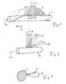
- Fig. 1shows a rotor shaft 1 with an airfoil 2, which is composed of individual, schematically indicated slats 3, 4, 5.
- the individual disksare each pivotally mounted on the rotor shaft 1 with their base points 3a, 4a, 5a, wherein the base points of the disks rotate around the rotor shaft 1 as a whole in a helical manner.
- the particular embodiment of the blade according to the inventionis described in more detail from the Fig. 2 out.
- the lamellae 3, 4, 5are shown in clamped, expanded form of the airfoil, wherein the adjacent lamellae closely abut each other with their longitudinal sides and thus form a smooth and dense surface for the flowing fluid.
- the paddle wheelcan be largely compressed, d. H. with respect to the radius, based on the rotor shaft 1 or reduce its longitudinal axis 1a.
- Fig. 2shows a pivoting of the individual slats in the longitudinal direction of the rotor shaft 1 in the plane of the rotor shaft axis indicated, the invention is not limited thereto.
- Fig. 3shows a pivoting of a blade 3 in the azimuthal direction, as indicated by the arrow 9.
- Fig. 4shows a further variant of such a configuration, wherein webs 10, 11 are provided on the rotor shaft 1 and the blades 3, 4 on the helical around the rotor shaft 1 encircling webs 10, 11 are pivotally mounted.
- the pivoted positionsare in the Fig. 4 each shown in dashed lines.
- the individual lamellaecan also be fastened to transverse struts of the rotor shaft 1 and extend in the clamped state parallel to the longitudinal axis of the rotor shaft. It is important that they can be individually folded to reduce the diameter of the rotor.
- Fig. 5schematically is a plan view of four fins 12, 13, 14, 15 are shown, each rectangular in cross-section and hollow in order to produce greater longitudinal stiffness of the individual slats. The goal is that despite the rigidity of the individual blades, the entire blade is easy to fold.
- the Fig. 6shows two configurations of lamellae, wherein on the left side in each case lamellae 16, 17 are shown, which have a cover lip 18, 19, wherein adjacent lamellae are sealed on the one hand on the cover lip 18, 19 of the adjacent lamella and on the other hand. This results in a stiffening of the entire Airfoil so that the airfoil can withstand increased fluid backpressure during operation.
- each of the lamellaehas a radially extending in the radial direction of the rotor shaft 1 web 20a, 21a, 22a.
- Fig. 7shows on the left side of the plan view of the rotor shaft 1, three lamellae 23, 24, 25, each on its longitudinal side surface on one side 26 a convex protuberance, on the other side 27 have a concave indentation, so that adjacent lamellae interlock and so opposite can support each other in an azimuthal pivoting movement.
- lamellae 28, 29are shown, wherein each of the lamellae on their longitudinal sides have a concave and a convex bulge with a round cross-section.
- This designhas the advantage that adjacent lamellae are mutually limited to rotate about their longitudinal axis.
- the individual lamellaecan either be fastened to the rotor shaft 1 by means of a pivot joint or designed so flexible or flexible in their foot region that they can be pivoted as a whole relative to the rotor shaft.
- the individual slatscan also be glued individually with their foot ends on a flexible band or attached to this in another way, the band can be fixed as a whole with the lamellae on the rotor. Due to the flexibility of the band then the pivoting of the individual slats can be ensured.
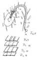
- FIG. 8schematically the use of a fluid pump is shown with an airfoil according to the invention, wherein the pump 30 is positioned in a heart chamber 31 and, as indicated by the arrows 32, sucks blood, which is conveyed into a vessel 33, as shown by the arrows 34 ,
- the pump 30is mounted on a catheter 35, through which runs centrally a shaft 1 shown only in the region of the pump 30, which is driven in rotation by means of a motor 36.
- the shaftmoves a rotor 37, which has an only schematically illustrated airfoil.
- the pump 30has a diameter which, in the extreme case, may possibly also be greater than the inner diameter of the vessel 33.
- the paddle wheelis fully expanded.
- itcan also be compressed to introduce or remove the pump 30, wherein the individual blades, as shown above, can be folded onto the rotor shaft 1 and at the same time the housing of the pump 30 collapses accordingly.
- this housingfor example, consist of a membrane which is clamped by a framework or by the fluid pressure generated in the pump 30.
- FIG. 9shows three flat, overlapping on their longitudinal sides lamellae, which may for example have a Velcro connection in their overlap region.
- FIG. 10shows lamellas which have along their longitudinal sides each 90 degrees angled edges, with which they hook into each other, while in FIG. 11 a variant with an angle less than 90 degrees, which also allows a fixation of the slats relative to each other.
- FIG. 12Finally, there is a variant with a curved edge, which serves the same purpose of mutual fixation.
Landscapes
- Engineering & Computer Science (AREA)
- Health & Medical Sciences (AREA)
- Mechanical Engineering (AREA)
- Heart & Thoracic Surgery (AREA)
- Cardiology (AREA)
- General Health & Medical Sciences (AREA)
- Animal Behavior & Ethology (AREA)
- Veterinary Medicine (AREA)
- Public Health (AREA)
- Anesthesiology (AREA)
- Biomedical Technology (AREA)
- Hematology (AREA)
- Life Sciences & Earth Sciences (AREA)
- General Engineering & Computer Science (AREA)
- Physics & Mathematics (AREA)
- Optics & Photonics (AREA)
- Plasma & Fusion (AREA)
- Vascular Medicine (AREA)
- Thermal Sciences (AREA)
- Structures Of Non-Positive Displacement Pumps (AREA)
- External Artificial Organs (AREA)
Abstract
Description
Translated fromGermanDie vorliegende Erfindung liegt auf dem Gebiet der Mechanik bzw. Mikromechanik und kann insbesondere in der medizinischen Technik mit Vorteil angewendet werden.The present invention is in the field of mechanics or micromechanics and can be used particularly advantageously in medical technology.
Die Erfindung bezieht sich auf ein Schaufelblatt für eine Pumpe und dessen Gestaltung. Dabei handelt es sich um eine Pumpe mit einem Rotor, wobei der Rotor komprimierbar und expandierbar ist, um die Gesamtabmaße der Pumpe gegebenenfalls verändern zu können. Auf diese Weise kann die Pumpe durch schwierig zugängliche Öffnungen bzw. in enge Röhrensysteme geschoben werden, wozu sie zunächst komprimiert und, nachdem sie an den Einsatzort gebracht ist, wieder expandiert wird.The invention relates to an airfoil for a pump and its design. It is a pump with a rotor, wherein the rotor is compressible and expandable in order to change the overall dimensions of the pump, if necessary. In this way, the pump can be pushed through difficult-to-access openings or in narrow tube systems, what they initially compressed and, after it is brought to the site, is expanded again.
Besonders vorteilhaft ist eine solche Pumpe in der Medizintechnik auf dem Gebiet der Herzpumpen oder anderer Pumpen für Körperflüssigkeiten einsetzbar, die üblicherweise mit Kathetern verwendet werden.Such a pump is particularly advantageously used in medical technology in the field of cardiac pumps or other pumps for body fluids, which are usually used with catheters.
Es sind auf dem medizintechnischen Gebiet verschiedene Arten von Mikropumpen bekannt, die in komprimiertem Zustand mit einem Katheter durch ein körpereigenes Gefäß in einen Patientenkörper eingebracht und an Ort und Stelle expandiert werden können. Um eine entsprechende radiale Komprimierbarkeit und Expandierbarkeit zu erzeugen, können verschiedene Effekte bei der Konstruktion und dem Bau des Pumpengehäuses und des Pumpenrotors verwendet werden, wie z. B. der Einsatz von sogenannten Gedächtnislegierungen, die in Abhängigkeit von der Umgebungstemperatur ihre Form ändern, oder durch das Vorsehen bestimmter Übertragungsmechanismen, die es erlauben, den Pumpendurchmesser gezielt zu steuern.Various types of micropumps are known in the medical field, which can be introduced in a compressed state with a catheter through a body-own vessel in a patient's body and expanded in place. In order to produce a corresponding radial compressibility and expandability, various effects can be used in the design and construction of the pump housing and the pump rotor, such as. As the use of so-called memory alloys that change their shape depending on the ambient temperature, or by the provision of certain transmission mechanisms that allow to control the pump diameter targeted.
Aus der
Aus dem Patentdokument
Aus der US-Patentschrift
Der vorliegenden Erfindung liegt vor dem Hintergrund des Standes der Technik die Aufgabe zugrunde, einen möglichst einfach und kostengünstig herzustellenden Rotor bzw. ein Schaufelblatt für einen solchen Rotor herzustellen, wobei im Vordergrund eine hohe Komprimierbarkeit mit möglichst geringem Kraftaufwand steht, so dass zum Herausziehen der Pumpe aus dem Gefäß die Kompression des Pumpenrotors ohne größere äußere Widerstände realisiert werden kann. Zudem soll die entsprechende Pumpe leistungsfähig und verbrauchsarm gestaltet sein.The present invention is based on the background of the prior art, the object to produce a simple and inexpensive to manufacture rotor or an airfoil for such a rotor, with a high compressibility in the foreground with the least possible effort, so that to pull out the pump from the vessel the compression of the pump rotor can be realized without larger external resistances. In addition, the corresponding pump should be designed powerful and low consumption.
Die Aufgabe wird gemäß der Erfindung mit den Merkmalen des Patentanspruchs 1 gelöst.The object is achieved according to the invention with the features of
Die Erfindung sieht ein Schaufelblatt mit mehreren Lamellen vor, die nebeneinander angeordnet, gegeneinander beweglich und gegenüber einer Drehachse des Rotors schwenkbar sind, wobei die Lamellen im expandierten Zustand des Schaufelblattes derart aneinander anliegen, dass sie gemeinsam eine durchgehende Schaufelblattfläche bilden.The invention provides an airfoil having a plurality of fins, which are arranged side by side, against each other and movable with respect to a rotational axis of the rotor, wherein the fins in the expanded state of the airfoil abut each other such that they together form a continuous airfoil surface.
Derartige Lamellen lassen sich einzeln durch ihre Schwenkbarkeit sehr leicht in einen Platz sparenden Zustand schwenken und bilden im ausgeschwenkten, expandierten Zustand des Schaufelblatts bzw. des Rotors eine geschlossene Schaufelblattfläche, die derart konzipiert ist, dass sie die notwendigen strömungstechnischen Bedingungen hinsichtlich Formgebung und Oberflächengestaltung erfüllt.Such lamellae can be pivoted individually by their pivoting very easily in a space-saving state and form in the swung, expanded state of the blade or the rotor a closed blade surface, the is designed so that it meets the necessary fluidic conditions in terms of shaping and surface design.
Gegenüber einer faltbaren Membran hat das aus einzelnen Lamellen bestehende Schaufelblatt den Vorteil, dass seine Bestandteile sowohl im komprimierten als auch im expandierten Zustand eine definierte Form und Anordnung einnehmen können. Die einzelnen Lamellen können jeweils für sich an der Welle des Rotors schwenkbar befestigt sein, und zwar vorteilhaft schwenkbar in einer Ebene, die die Längsachse der Rotorwelle enthält oder eine zu einer solchen Welle parallele Achse, wobei die Befestigungspunkte wendelförmig um die Rotorwelle umlaufen können, um im ausgeklappten Zustand ein wendelförmiges Schaufelblatt zu erzeugen. Es sind jedoch auch andere Befestigungsarten denkbar, bei denen die Lamellen beispielsweise an einem oder mehreren Stegen oder Querholmen befestigt sind, die ihrerseits mit der Rotorwelle verbunden sind.Compared to a foldable membrane, the blade made of individual lamellae has the advantage that its components can assume a defined shape and arrangement both in the compressed state and in the expanded state. The individual lamellae may each be pivotally mounted on the shaft of the rotor, and advantageously pivotally in a plane containing the longitudinal axis of the rotor shaft or an axis parallel to such a shaft, wherein the attachment points can rotate helically around the rotor shaft to to produce a helical blade in the unfolded state. However, there are also other types of attachment conceivable in which the slats are attached, for example, to one or more webs or cross beams, which in turn are connected to the rotor shaft.
Die einzelnen Lamellen können gleich lang, jedoch auch unterschiedlich lang ausgeführt sein, je nachdem, welche Endform das Schaufelblatt annehmen soll. Die Schwenkbarkeit der einzelnen Lamellen ist begrenzt, so dass diese im aufgeklappten Zustand dem Strömungsgegendruck eines zu befördernden Fluids standhalten können. Die Lamellen können sich jedoch auch gegenseitig dadurch stützen, dass sie aneinander anliegen und gegebenenfalls verriegelnd ineinander greifen. Beispielsweise können die Lamellen nach Art der Elemente einer Vogelfeder konzipiert sein, wobei der Kiel der Feder in dem Vergleich der Rotorwelle entspricht.The individual lamellae can be of the same length but also of different lengths, depending on which final shape the blade is to assume. The pivotability of the individual slats is limited, so that they can withstand the flow back pressure of a fluid to be transported in the unfolded state. However, the slats can also mutually support that they rest against each other and interlock if necessary interlocking. For example, the lamellae may be designed in the manner of the elements of a bird's feather, the keel corresponding to the spring in the comparison of the rotor shaft.
Die Konstruktion des Schaufelblattes kann derart konzipiert sein, dass das Schaufelblatt bei Drehung in Betriebsrichtung durch den Fluidgegendruck expandiert und bei Drehung in der entgegengesetzten Richtung durch die Wirkung des Mediums, in dem sich das Schaufelblatt bewegt, komprimiert wird. Dies macht die Kompressions- und Expansionsbewegung besonders einfach, ohne dass größere Kräfte zu überwinden sind. Dadurch lässt sich bei einer Anwendung im medizinischen Gebiet eine derartige Pumpe einfach und ohne eine Gefahr, Körpergefäße zu beschädigen, wieder entfernen.The construction of the airfoil may be designed such that the airfoil, upon rotation in the operating direction, expands by the fluid counterpressure and compresses upon rotation in the opposite direction by the action of the medium in which the airfoil moves. This makes the compression and expansion movement particularly easy, without larger forces to be overcome. As a result, when used in the medical field such a pump can be removed easily and without any risk of damaging body vessels.
Eine besondere Ausgestaltung der Erfindung sieht vor, dass wenigstens zwei Lamellen, insbesondere jede der Lamellen für sich formstabil, insbesondere steif ausgebildet ist.A particular embodiment of the invention provides that at least two fins, in particular each of the fins is dimensionally stable, in particular rigid.
Das Schaufelblatt gewinnt seine Flexibilität nicht durch die Flexibilität einer Membran, sondern durch die Beweglichkeit der einzelnen Lamellen relativ zueinander. Dazu dürfen die Lamellen eine bestimmte Breite nicht überschreiten. Vorteilhaft kann beispielsweise das Schaufelblatt aus mindestens 10 oder mindestens 50 Lamellen bestehen. Ein solches Schaufelblatt kann insgesamt eine sehr kleine Baugröße aufweisen, um in ein Blutgefäß geschoben zu werden, beispielsweise im komprimierten Zustand einen Durchmesser von 2 mm.The airfoil gains its flexibility not by the flexibility of a membrane, but by the mobility of the individual slats relative to each other. For this purpose, the slats must not exceed a certain width. Advantageously, for example, the airfoil consist of at least 10 or at least 50 fins. Overall, such an airfoil can have a very small size in order to be pushed into a blood vessel, for example in the compressed state a diameter of 2 mm.
Eine weitere vorteilhafte Ausgestaltung der Erfindung kann vorsehen, dass jeweils benachbarte Lamellen entlang einer Längsseite, die sich bezüglich der Rotorachse wenigstens teilweise radial erstreckt, dichtend aneinander anliegen.A further advantageous embodiment of the invention can provide that each adjacent lamellae sealingly abut one another along a longitudinal side which extends at least partially radially with respect to the rotor axis.
Wenn es auch denkbar ist, dass die Lamellen zwischen sich Zwischenräume freilassen, so steigt doch die Effizienz der Fluidpumpe mit der Dichtigkeit des durch die Lamellen gebildeten Schaufelblatts. Es ist daher vorteilhaft, wenn die Lamellen an ihrer Längsseite jeweils aneinanderstoßen und möglichst dort keinen Zwischenraum freilassen.Although it is also conceivable that the lamellae leave gaps between them, the efficiency of the fluid pump increases with the tightness of the lamellae formed by the lamellae. It is therefore advantageous if the lamellae abut each other on their longitudinal side and leave as far as possible no gap there.
Es kann zudem vorgesehen sein, dass jeweils einander direkt benachbarte Lamellen derart aneinanderliegen, dass sie um die Rotorachse in wenigstens einem Richtungssinn nicht gegeneinander schwenkbar sind. Damit können sich die einzelnen Lamellen gegenseitig stützen und im Betrieb dem Gegendruck des zu pumpenden Fluids insgesamt standhalten. Insbesondere dann, wenn die Lamellen am Umfang der Rotorwelle wendelförmig verteilt sind, ist eine Stützung in azimutaler Richtung gegeben.It may also be provided that in each case directly adjacent lamellae lie against each other such that they are not pivotable about the rotor axis in at least one sense of direction against each other. Thus, the individual slats can support each other and withstand the back pressure of the fluid to be pumped in total operation. In particular, when the lamellae are distributed helically on the circumference of the rotor shaft, a support in the azimuthal direction is given.
Die Erfindung kann zudem derart ausgestaltet sein, dass jeweils benachbarte Lamellen einander im Bereich der Längsseite überlappen. Durch eine Überlappung der Lamellen wird eine besonders hohe Dichtigkeit erzeugt, und außerdem kann im Überlappungsbereich die Stützfunktion der Lamellen gegenseitig ausgeübt werden.The invention can also be designed such that adjacent lamellae overlap each other in the region of the longitudinal side. By overlapping the slats, a particularly high density is generated, and also in the overlapping area, the support function of the slats can be mutually exerted.
Eine besonders hohe Stabilität und Dichtigkeit zwischen den Lamellen wird dadurch erreicht, dass jeweils benachbarte Lamellen im Bereich der Längsseite ineinandergreifen. Dabei kann jede Art von formschlüssiger Gestaltung benachbarter Lamellen vorgesehen sein, beispielsweise jeweils das Vorsehen einer Falz entlang der Längsseiten der Lamellen, beispielsweise auch in Form einer dünnen Dichtlippe.A particularly high stability and tightness between the slats is achieved in that adjacent slats intermesh in the region of the longitudinal side. In this case, any type of form-fitting design of adjacent slats can be provided, for example, in each case the provision of a fold along the longitudinal sides of the slats, for example, in the form of a thin sealing lip.
Um eine formschlüssige und dichte Verbindung herzustellen, kann auch vorgesehen sein, dass wenigstens eine Lamelle, insbesondere alle Lamellen, im Querschnitt an einer ihrer Längsseiten eine konvexe Form und an der anderen Längsseite eine konkave Form aufweist. Die entsprechende konvexe oder konkave Struktur kann im Querschnitt rund, elliptisch oder auch als Nut oder Einkerbung gestaltet sein.In order to produce a positive and tight connection, it can also be provided that at least one lamella, in particular all lamellae, has a convex shape in cross-section on one of its longitudinal sides and a concave shape on the other longitudinal side. The corresponding convex or concave structure may be round, elliptical in cross-section or also designed as a groove or notch.
Vorteilhaft können jeweils benachbarte Lamellen durch ein biegeschlaffes Element, insbesondere ein Band oder eine Membran, miteinander verbunden sein. Die Ausklappbarkeit des Schaufelblattes ergibt sich dann nach Art eines Fächers, bei dem breite, steife Stützstäbe durch schmale Membranen oder Bänder miteinander verbunden sind.Advantageously, adjacent lamellae can be connected to each other by a flexible element, in particular a band or a membrane. The Ausklappbarkeit of the airfoil then results in the manner of a fan in which wide, rigid support rods are connected by narrow membranes or bands together.
Zur Stabilisierung der einzelnen Lamellen können diese jeweils im Querschnitt eine Versteifungsstruktur aufweisen, die beispielsweise einen in Längsrichtung verlaufenden Steg vorsieht. Es kann jedoch auch vorgesehen sein, dass zusätzlich oder alternativ die einzelnen Lamellen hohl mit rundem oder eckigem Querschnitt ausgebildet sind.To stabilize the individual lamellae, these can each have, in cross-section, a stiffening structure which, for example, provides a web extending in the longitudinal direction. However, it can also be provided that, additionally or alternatively, the individual slats are hollow with a round or rectangular cross-section.
Vorteilhaft kann die Erfindung ausgebildet werden durch ein Schaufelblatt bei dem wenigstens zwei Lamellen durch eine klettartige Verbindung miteinander verbunden sind. Eine solche klettartige Verbindung besteht aus kleinen hakenartigen Elementen auf der einen und Schlaufenartigen Elementen auf der jeweils anderen Seite, die vorteilhaft mikroskopisch klein ausgebildet sein können.Advantageously, the invention can be formed by an airfoil in which at least two blades are connected to each other by a velcro connection. Such a velcro connection consists of small hook-like elements on one side and loop-like elements on the other side, which can advantageously be formed microscopically small.
Die Erfindung kann weiter dadurch vorteilhaft ausgestaltet sein, dass die Verbindung durch Aufbringen einer Belastung auf das Schaufelblatt in Axialrichtung des Rotors und/oder durch Relativbewegung zweier benachbarter Lamellen entlang ihrer jeweiligen Längsseiten und in Längsrichtung der Lamellen lösbar ist.The invention can be further advantageously characterized in that the connection by applying a load on the blade in the axial direction of the rotor and / or by relative movement of two adjacent blades along their respective longitudinal sides and in the longitudinal direction of the blades is solvable.
Die Längsrichtung der Lamellen ist dabei durch die Richtung gegeben, in der sich die jeweilige Lamelle von der Rotorwelle weg erstreckt.The longitudinal direction of the lamellae is given by the direction in which the respective lamella extends away from the rotor shaft.
Durch die beschriebene Struktur eines Schaufelblattes für den Rotor einer Fluidpumpe kann dieses besonders stabil und definiert komprimierbar gestaltet werden, wodurch sich insbesondere eine gute Komprimierbarkeit und ein geringer Enddurchmesser des Rotors in der komprimierten Form erreichen lässt.As a result of the described structure of an airfoil blade for the rotor of a fluid pump, it can be designed in a particularly stable and defined compressible manner, which makes it possible in particular to achieve a good compressibility and a small end diameter of the rotor in the compressed form.
Die Erfindung wird im Folgenden anhand eines Ausführungsbeispiels in einer Zeichnung gezeigt und anschließend beschrieben.The invention will be shown below with reference to an embodiment in a drawing and described.
Dabei zeigt:
- Fig. 1
- schematisch in einer dreidimensionalen Ansicht eine Rotorwelle sowie ein Schaufel- blatt,
- Fig. 2
- schematisch einen Teil eines Schaufel- blattes mit mehreren Lamellen,
- Fig. 3
- eine Rotorwelle im Querschnitt mit einer Lamelle in zwei Positionen,
- Fig. 4
- eine Rotorwelle im Querschnitt mit zwei Lamellen in jeweils zwei Positionen,
- Fig. 5
- eine Ansicht einer Rotorwelle mit vier Lamellen,
- Fig. 6
- eine Ansicht einer Rotorwelle mit zwei Konfigurationen von Lamellen,
- Fig. 7
- eine Ansicht einer Rotorwelle mit zwei Konfigurationen von Lamellen sowie
- Fig. 8
- eine schematische Darstellung einer Herz- katheterpumpe mit einem Rotor und Schaufel- blättern in einer Herzkammer,
- Figuren 9
bis 12 - zeigenschematische 3-dimensionale Darstellungen überlappender Lamellen.
- Fig. 1
- FIG. 2 is a schematic view of a rotor shaft and a blade blade in a three-dimensional view. FIG.
- Fig. 2
- schematically a part of a blade blade with a plurality of blades,
- Fig. 3
- a rotor shaft in cross-section with a blade in two positions,
- Fig. 4
- a rotor shaft in cross-section with two blades in two positions,
- Fig. 5
- a view of a rotor shaft with four fins,
- Fig. 6
- a view of a rotor shaft with two configurations of fins,
- Fig. 7
- a view of a rotor shaft with two configurations of slats as well
- Fig. 8
- 1 is a schematic representation of a cardiac catheter pump with a rotor and blades in a heart chamber,
- FIGS. 9 to 12
- Schematic 3-dimensional representations of overlapping lamellae.
Auf diese Weise wird eine helixförmige Struktur eines Schaufelblattes geschaffen, die bei Rotation um die Rotorwelle 1 eine axiale Beförderung einer Flüssigkeit in Richtung des Pfeils 6 bewirkt.In this way, a helical structure of an airfoil is created, which causes an axial transport of a liquid in the direction of the
Die besondere Ausgestaltung des erfindungsgemäßen Schaufelblattes geht detaillierter aus der
In der Position, die gestrichelt dargestellt und mit 7 bezeichnet ist, sind die einzelnen Lamellen ein Stück weit an die Rotorwelle 1 angeklappt, wobei für die Deformierbarkeit des Schaufelblattes insgesamt wichtig ist, dass die einzelnen Lamellen 3, 4, 5 gegeneinander beweglich, insbesondere in Längsrichtung verschiebbar sind. Dadurch ist kein Falten der entsprechenden Fläche notwendig, sondern die einzelnen Lamellen können bis weit zur Rotorwelle hin angeklappt werden, wie in der weiteren Position 8 der Lamellen dargestellt ist.In the position shown in dashed lines and designated 7, the individual lamellae are folded a little way to the
Hierdurch lässt sich das Schaufelrad weitgehend komprimieren, d. h. bezüglich des Radius, bezogen auf die Rotorwelle 1 oder deren Längsachse 1a reduzieren.As a result, the paddle wheel can be largely compressed, d. H. with respect to the radius, based on the
Es entstehen dabei auch keine nennenswerten elastischen Gegenkräfte, so dass der Rotor praktisch kraftfrei komprimiert werden kann, wenn dies beispielsweise zum Einführen oder Entfernen einer entsprechenden Fluidpumpe aus einem körpereigenen Gefäß notwendig ist.There are also no significant elastic counterforces, so that the rotor can be compressed virtually force-free, if this is necessary for example for introducing or removing a corresponding fluid pump from a body-own vessel.
Ist in der
Es wird deutlich, dass das Schwenken der Lamellen in der jeweils gestrichelt dargestellten Position zu einer Komprimierung des Rotors führt. Beispielsweise kann eine Komprimierung des Rotors durch einen Drehbetrieb des Rotors in einer der Betriebsrichtung entgegengesetzten Richtung hervorgerufen werden. Das Aufspannen des Rotors geschieht entsprechend durch Rotation in der Betriebsrichtung.It is clear that the pivoting of the slats in the position shown in dashed lines in each case leads to a compression of the rotor. For example, a compression of the rotor may be caused by a rotary operation of the rotor in a direction opposite to the operating direction. The clamping of the rotor is done accordingly by rotation in the operating direction.
Grundsätzlich können die einzelnen Lamellen auch an Querholmen der Rotorwelle 1 befestigt sein und im aufgespannten Zustand parallel zur Längsachse der Rotorwelle verlaufen. Wichtig ist, dass sie zur Durchmesserreduktion des Rotors entsprechend einzeln einklappbar sind.In principle, the individual lamellae can also be fastened to transverse struts of the
In der
Die
Auf der rechten Seite der
Auf der rechten Seite der
Grundsätzlich können die einzelnen Lamellen entweder mittels eines Schwenkgelenkes an der Rotorwelle 1 befestigt oder in ihrem Fußbereich derart biegsam bzw. flexibel ausgestaltet sein, dass sie jedenfalls als Ganzes gegenüber der Rotorwelle schwenkbar sind. Die einzelnen Lamellen können auch mit ihren Fußenden jeweils einzeln auf ein flexibles Band aufgeklebt oder an diesem auf andere Weise befestigt sein, wobei das Band als Ganzes mit den Lamellen auf dem Rotor befestigt werden kann. Durch die Flexibilität des Bandes kann dann die Schwenkbarkeit der einzelnen Lamellen gewährleistet sein.In principle, the individual lamellae can either be fastened to the
In der
Die Pumpe 30 weist im expandierten Zustand einen Durchmesser auf, der im Extremfall möglicherweise auch größer als der Innendurchmesser des Gefäßes 33 sein kann. Zu diesem Zweck wird das Schaufelrad voll expandiert. Es kann jedoch zum Einbringen oder Entnehmen der Pumpe 30 auch komprimiert werden, wobei die einzelnen Lamellen, wie oben dargestellt, an die Rotorwelle 1 angeklappt werden können und gleichzeitig das Gehäuse der Pumpe 30 entsprechend kollabiert. Dazu kann dieses Gehäuse beispielsweise aus einer Membran bestehen, die durch ein Gerüst oder durch den in der Pumpe 30 erzeugten Fluiddruck aufgespannt wird.In the expanded state, the
Claims (14)
Translated fromGermanPriority Applications (8)
| Application Number | Priority Date | Filing Date | Title |
|---|---|---|---|
| EP09075276AEP2266640A1 (en) | 2009-06-25 | 2009-06-25 | Compressible and expandable turbine blade for a fluid pump |
| PCT/EP2010/004023WO2010149393A1 (en) | 2009-06-25 | 2010-06-25 | Compressible and expandable blade for a fluid pump |
| US13/261,100US9067006B2 (en) | 2009-06-25 | 2010-06-25 | Compressible and expandable blade for a fluid pump |
| DE112010002711.0TDE112010002711B4 (en) | 2009-06-25 | 2010-06-25 | Compressible and expandable blade for a fluid pump |
| US14/754,395US10330101B2 (en) | 2009-06-25 | 2015-06-29 | Compressible and expandable blade for a fluid pump |
| US16/404,800US11268521B2 (en) | 2009-06-25 | 2019-05-07 | Compressible and expandable blade for a fluid pump |
| US17/582,676US11994133B2 (en) | 2009-06-25 | 2022-01-24 | Compressible and expandable blade for a fluid pump |
| US18/640,529US12372092B2 (en) | 2009-06-25 | 2024-04-19 | Compressible and expandable blade for a fluid pump |
Applications Claiming Priority (1)
| Application Number | Priority Date | Filing Date | Title |
|---|---|---|---|
| EP09075276AEP2266640A1 (en) | 2009-06-25 | 2009-06-25 | Compressible and expandable turbine blade for a fluid pump |
Publications (1)
| Publication Number | Publication Date |
|---|---|
| EP2266640A1true EP2266640A1 (en) | 2010-12-29 |
Family
ID=41162697
Family Applications (1)
| Application Number | Title | Priority Date | Filing Date |
|---|---|---|---|
| EP09075276AWithdrawnEP2266640A1 (en) | 2009-06-25 | 2009-06-25 | Compressible and expandable turbine blade for a fluid pump |
Country Status (4)
| Country | Link |
|---|---|
| US (5) | US9067006B2 (en) |
| EP (1) | EP2266640A1 (en) |
| DE (1) | DE112010002711B4 (en) |
| WO (1) | WO2010149393A1 (en) |
Cited By (11)
| Publication number | Priority date | Publication date | Assignee | Title |
|---|---|---|---|---|
| US10722631B2 (en) | 2018-02-01 | 2020-07-28 | Shifamed Holdings, Llc | Intravascular blood pumps and methods of use and manufacture |
| US11185677B2 (en) | 2017-06-07 | 2021-11-30 | Shifamed Holdings, Llc | Intravascular fluid movement devices, systems, and methods of use |
| US11511103B2 (en) | 2017-11-13 | 2022-11-29 | Shifamed Holdings, Llc | Intravascular fluid movement devices, systems, and methods of use |
| US11654275B2 (en) | 2019-07-22 | 2023-05-23 | Shifamed Holdings, Llc | Intravascular blood pumps with struts and methods of use and manufacture |
| US11724089B2 (en) | 2019-09-25 | 2023-08-15 | Shifamed Holdings, Llc | Intravascular blood pump systems and methods of use and control thereof |
| US11964145B2 (en) | 2019-07-12 | 2024-04-23 | Shifamed Holdings, Llc | Intravascular blood pumps and methods of manufacture and use |
| US12102815B2 (en) | 2019-09-25 | 2024-10-01 | Shifamed Holdings, Llc | Catheter blood pumps and collapsible pump housings |
| US12121713B2 (en) | 2019-09-25 | 2024-10-22 | Shifamed Holdings, Llc | Catheter blood pumps and collapsible blood conduits |
| US12161857B2 (en) | 2018-07-31 | 2024-12-10 | Shifamed Holdings, Llc | Intravascular blood pumps and methods of use |
| US12220570B2 (en) | 2018-10-05 | 2025-02-11 | Shifamed Holdings, Llc | Intravascular blood pumps and methods of use |
| US12409310B2 (en) | 2019-12-11 | 2025-09-09 | Shifamed Holdings, Llc | Descending aorta and vena cava blood pumps |
Families Citing this family (94)
| Publication number | Priority date | Publication date | Assignee | Title |
|---|---|---|---|---|
| US7393181B2 (en) | 2004-09-17 | 2008-07-01 | The Penn State Research Foundation | Expandable impeller pump |
| CN102380135A (en) | 2006-03-23 | 2012-03-21 | 宾州研究基金会 | Heart assist device with expandable impeller pump |
| EP2194278A1 (en) | 2008-12-05 | 2010-06-09 | ECP Entwicklungsgesellschaft mbH | Fluid pump with a rotor |
| EP2216059A1 (en) | 2009-02-04 | 2010-08-11 | ECP Entwicklungsgesellschaft mbH | Catheter device with a catheter and an actuation device |
| EP2229965A1 (en) | 2009-03-18 | 2010-09-22 | ECP Entwicklungsgesellschaft mbH | Fluid pump with particular form of a rotor blade |
| EP2246078A1 (en) | 2009-04-29 | 2010-11-03 | ECP Entwicklungsgesellschaft mbH | Shaft assembly with a shaft which moves within a fluid-filled casing |
| EP2248544A1 (en) | 2009-05-05 | 2010-11-10 | ECP Entwicklungsgesellschaft mbH | Fluid pump with variable circumference, particularly for medical use |
| EP2266640A1 (en) | 2009-06-25 | 2010-12-29 | ECP Entwicklungsgesellschaft mbH | Compressible and expandable turbine blade for a fluid pump |
| EP2282070B1 (en) | 2009-08-06 | 2012-10-17 | ECP Entwicklungsgesellschaft mbH | Catheter device with a coupling device for a drive device |
| EP2299119B1 (en) | 2009-09-22 | 2018-11-07 | ECP Entwicklungsgesellschaft mbH | Inflatable rotor for a fluid pump |
| EP2298373A1 (en) | 2009-09-22 | 2011-03-23 | ECP Entwicklungsgesellschaft mbH | Fluid pump with at least one turbine blade and a seating device |
| EP2298372A1 (en) | 2009-09-22 | 2011-03-23 | ECP Entwicklungsgesellschaft mbH | Rotor for an axial pump for transporting a fluid |
| EP2298371A1 (en) | 2009-09-22 | 2011-03-23 | ECP Entwicklungsgesellschaft mbH | Function element, in particular fluid pump with a housing and a transport element |
| EP2314330A1 (en) | 2009-10-23 | 2011-04-27 | ECP Entwicklungsgesellschaft mbH | Flexible shaft arrangement |
| EP2314331B1 (en) | 2009-10-23 | 2013-12-11 | ECP Entwicklungsgesellschaft mbH | Catheter pump arrangement and flexible shaft arrangement with a cable core |
| EP2338539A1 (en) | 2009-12-23 | 2011-06-29 | ECP Entwicklungsgesellschaft mbH | Pump device with a detection device |
| EP2338541A1 (en) | 2009-12-23 | 2011-06-29 | ECP Entwicklungsgesellschaft mbH | Radial compressible and expandable rotor for a fluid pump |
| EP2338540A1 (en) | 2009-12-23 | 2011-06-29 | ECP Entwicklungsgesellschaft mbH | Delivery blade for a compressible rotor |
| EP2347778A1 (en) | 2010-01-25 | 2011-07-27 | ECP Entwicklungsgesellschaft mbH | Fluid pump with a radially compressible rotor |
| EP2363157A1 (en) | 2010-03-05 | 2011-09-07 | ECP Entwicklungsgesellschaft mbH | Device for exerting mechanical force on a medium, in particular fluid pump |
| EP2388029A1 (en) | 2010-05-17 | 2011-11-23 | ECP Entwicklungsgesellschaft mbH | Pump array |
| EP2399639A1 (en) | 2010-06-25 | 2011-12-28 | ECP Entwicklungsgesellschaft mbH | System for introducing a pump |
| EP2407185A1 (en) | 2010-07-15 | 2012-01-18 | ECP Entwicklungsgesellschaft mbH | Radial compressible and expandable rotor for a pump with a turbine blade |
| EP2407187A3 (en) | 2010-07-15 | 2012-06-20 | ECP Entwicklungsgesellschaft mbH | Blood pump for invasive application within the body of a patient |
| EP2407186A1 (en) | 2010-07-15 | 2012-01-18 | ECP Entwicklungsgesellschaft mbH | Rotor for a pump, produced with an initial elastic material |
| EP2422735A1 (en) | 2010-08-27 | 2012-02-29 | ECP Entwicklungsgesellschaft mbH | Implantable blood transportation device, manipulation device and coupling device |
| WO2012094641A2 (en) | 2011-01-06 | 2012-07-12 | Thoratec Corporation | Percutaneous heart pump |
| EP2497521A1 (en) | 2011-03-10 | 2012-09-12 | ECP Entwicklungsgesellschaft mbH | Push device for axial insertion of a string-shaped, flexible body |
| EP2564771A1 (en) | 2011-09-05 | 2013-03-06 | ECP Entwicklungsgesellschaft mbH | Medicinal product with a functional element for invasive use in the body of a patient |
| US8926492B2 (en) | 2011-10-11 | 2015-01-06 | Ecp Entwicklungsgesellschaft Mbh | Housing for a functional element |
| JP6139550B2 (en) | 2011-11-28 | 2017-05-31 | ミ‐ヴァド インコーポレイテッド | Auxiliary circulation apparatus and method |
| WO2013082621A1 (en) | 2011-12-03 | 2013-06-06 | Indiana University Research And Technology Corporation | Cavopulmonary viscous impeller assist device and method |
| US11389638B2 (en) | 2012-02-07 | 2022-07-19 | Hridaya, Inc. | Hemodynamic assist device |
| JP2015505515A (en)* | 2012-02-07 | 2015-02-23 | フリダヤ インコーポレーテッドHridaya, Inc. | Blood circulation assist device |
| US9327067B2 (en) | 2012-05-14 | 2016-05-03 | Thoratec Corporation | Impeller for catheter pump |
| EP4218887A1 (en) | 2012-05-14 | 2023-08-02 | Tc1 Llc | Mechanical circulatory support device for stabilizing a patient after cardiogenic shock |
| US8721517B2 (en) | 2012-05-14 | 2014-05-13 | Thoratec Corporation | Impeller for catheter pump |
| US9872947B2 (en) | 2012-05-14 | 2018-01-23 | Tc1 Llc | Sheath system for catheter pump |
| US9446179B2 (en) | 2012-05-14 | 2016-09-20 | Thoratec Corporation | Distal bearing support |
| CN108742951B (en) | 2012-06-06 | 2021-05-25 | 洋红医疗有限公司 | Artificial kidney valve |
| US20130338690A1 (en)* | 2012-06-15 | 2013-12-19 | Gadal Consulting, LLC | Device and method for removing unwanted material in a vascular conduit |
| EP4186557A1 (en) | 2012-07-03 | 2023-05-31 | Tc1 Llc | Motor assembly for catheter pump |
| US9421311B2 (en) | 2012-07-03 | 2016-08-23 | Thoratec Corporation | Motor assembly for catheter pump |
| US9358329B2 (en) | 2012-07-03 | 2016-06-07 | Thoratec Corporation | Catheter pump |
| EP4233702A3 (en) | 2013-03-13 | 2023-12-20 | Magenta Medical Ltd. | Manufacture of an impeller |
| US11033728B2 (en) | 2013-03-13 | 2021-06-15 | Tc1 Llc | Fluid handling system |
| US11077294B2 (en) | 2013-03-13 | 2021-08-03 | Tc1 Llc | Sheath assembly for catheter pump |
| WO2014164136A1 (en) | 2013-03-13 | 2014-10-09 | Thoratec Corporation | Fluid handling system |
| US10583231B2 (en) | 2013-03-13 | 2020-03-10 | Magenta Medical Ltd. | Blood pump |
| US9308302B2 (en) | 2013-03-15 | 2016-04-12 | Thoratec Corporation | Catheter pump assembly including a stator |
| EP4190376A1 (en) | 2013-03-15 | 2023-06-07 | Tc1 Llc | Catheter pump assembly including a stator |
| EP2860849B1 (en) | 2013-10-11 | 2016-09-14 | ECP Entwicklungsgesellschaft mbH | Compressible motor, implanting assembly and method for positioning the motor |
| EP2868331B1 (en) | 2013-11-01 | 2016-07-13 | ECP Entwicklungsgesellschaft mbH | Pump, in particular blood pump |
| EP3110468B1 (en) | 2014-02-25 | 2021-11-03 | Kushwaha, Sudhir | Ventricular assist device and method |
| EP3131599B1 (en) | 2014-04-15 | 2019-02-20 | Tc1 Llc | Catheter pump with access ports |
| EP3131597B1 (en) | 2014-04-15 | 2020-12-02 | Tc1 Llc | Catheter pump introducer systems |
| WO2015160943A1 (en) | 2014-04-15 | 2015-10-22 | Thoratec Corporation | Sensors for catheter pumps |
| US10583232B2 (en) | 2014-04-15 | 2020-03-10 | Tc1 Llc | Catheter pump with off-set motor position |
| EP3583973A1 (en) | 2014-08-18 | 2019-12-25 | Tc1 Llc | Guide features for percutaneous catheter pump |
| EP3200846B1 (en) | 2014-10-01 | 2020-01-15 | Heartware, Inc. | Backup controller system with updating |
| US9770543B2 (en) | 2015-01-22 | 2017-09-26 | Tc1 Llc | Reduced rotational mass motor assembly for catheter pump |
| US9675738B2 (en) | 2015-01-22 | 2017-06-13 | Tc1 Llc | Attachment mechanisms for motor of catheter pump |
| WO2016118781A2 (en) | 2015-01-22 | 2016-07-28 | Thoratec Corporation | Motor assembly with heat exchanger for catheter pump |
| US9907890B2 (en) | 2015-04-16 | 2018-03-06 | Tc1 Llc | Catheter pump with positioning brace |
| WO2016185473A1 (en) | 2015-05-18 | 2016-11-24 | Magenta Medical Ltd. | Blood pump |
| CN105032636A (en)* | 2015-08-15 | 2015-11-11 | 重庆联合机器制造有限公司 | Assembly device of laminated gas-liquid spreader plates |
| EP3808401A1 (en) | 2016-07-21 | 2021-04-21 | Tc1 Llc | Gas-filled chamber for catheter pump motor assembly |
| US11160970B2 (en) | 2016-07-21 | 2021-11-02 | Tc1 Llc | Fluid seals for catheter pump motor assembly |
| CA3039285A1 (en) | 2016-10-25 | 2018-05-03 | Magenta Medical Ltd. | Ventricular assist device |
| JP7094279B2 (en) | 2016-11-23 | 2022-07-01 | マジェンタ・メディカル・リミテッド | Blood pump |
| CN110621851B (en)* | 2017-05-17 | 2021-08-06 | 联邦摩高气门机构公司 | Poppet valve and method of making the same |
| CN110662889B (en)* | 2017-05-17 | 2021-07-23 | 联邦摩高气门机构公司 | Poppet valve and method of manufacturing the same |
| US10905808B2 (en) | 2018-01-10 | 2021-02-02 | Magenta Medical Ltd. | Drive cable for use with a blood pump |
| EP3638336B1 (en) | 2018-01-10 | 2022-04-06 | Magenta Medical Ltd. | Ventricular assist device |
| DE102018201030B4 (en) | 2018-01-24 | 2025-10-16 | Kardion Gmbh | Magnetic dome element with magnetic bearing function |
| DE102018207575A1 (en) | 2018-05-16 | 2019-11-21 | Kardion Gmbh | Magnetic face turning coupling for the transmission of torques |
| DE102018207611A1 (en) | 2018-05-16 | 2019-11-21 | Kardion Gmbh | Rotor bearing system |
| DE102018208539A1 (en) | 2018-05-30 | 2019-12-05 | Kardion Gmbh | A motor housing module for sealing an engine compartment of a motor of a cardiac assist system and cardiac assistance system and method for mounting a cardiac assist system |
| DE102018208538A1 (en) | 2018-05-30 | 2019-12-05 | Kardion Gmbh | Intravascular blood pump and process for the production of electrical conductors |
| DE102018208541A1 (en) | 2018-05-30 | 2019-12-05 | Kardion Gmbh | Axial pump for a cardiac assist system and method of making an axial pump for a cardiac assist system |
| DE102018208550A1 (en) | 2018-05-30 | 2019-12-05 | Kardion Gmbh | A lead device for directing blood flow to a cardiac assist system, cardiac assist system, and method of making a lead device |
| DE102018210076A1 (en) | 2018-06-21 | 2019-12-24 | Kardion Gmbh | Method and device for detecting a state of wear of a cardiac support system, method and device for operating a cardiac support system and cardiac support system |
| DE102018210058A1 (en) | 2018-06-21 | 2019-12-24 | Kardion Gmbh | Stator blade device for guiding the flow of a fluid flowing out of an outlet opening of a heart support system, heart support system with stator blade device, method for operating a stator blade device and manufacturing method |
| DE102018211327A1 (en) | 2018-07-10 | 2020-01-16 | Kardion Gmbh | Impeller for an implantable vascular support system |
| DE102018212153A1 (en) | 2018-07-20 | 2020-01-23 | Kardion Gmbh | Inlet line for a pump unit of a cardiac support system, cardiac support system and method for producing an inlet line for a pump unit of a cardiac support system |
| US10851799B2 (en) | 2018-08-02 | 2020-12-01 | Percheron Power, LLC | Screw systems |
| CN112654389A (en) | 2018-08-07 | 2021-04-13 | 开迪恩有限公司 | Bearing device for a cardiac support system and method for flushing an intermediate space in a bearing device for a cardiac support system |
| AU2020211431B2 (en) | 2019-01-24 | 2024-10-24 | Magenta Medical Ltd | Ventricular assist device |
| US12097016B2 (en) | 2019-03-14 | 2024-09-24 | Abiomed, Inc. | Blood flow rate measurement system |
| EP3972661B1 (en) | 2019-05-23 | 2024-09-11 | Magenta Medical Ltd. | Blood pumps |
| DE102020102474A1 (en) | 2020-01-31 | 2021-08-05 | Kardion Gmbh | Pump for conveying a fluid and method for manufacturing a pump |
| EP3984589B1 (en) | 2020-04-07 | 2023-08-23 | Magenta Medical Ltd. | Magnetic phase sensing |
| DE102021120618A1 (en) | 2021-08-09 | 2023-02-23 | Fraunhofer-Gesellschaft zur Förderung der angewandten Forschung eingetragener Verein | Self-adaptive pump with shape memory element |
| US12257426B2 (en)* | 2022-12-02 | 2025-03-25 | Abiomed Europe Gmbh | Compressible rotor |
Citations (7)
| Publication number | Priority date | Publication date | Assignee | Title |
|---|---|---|---|---|
| EP0364293A2 (en)* | 1988-10-13 | 1990-04-18 | Kensey Nash Corporation | Blood pumping catheter |
| WO1994005347A1 (en)* | 1992-09-02 | 1994-03-17 | Reitan Oeyvind | Catheter pump |
| WO2003103745A2 (en) | 2002-06-11 | 2003-12-18 | Walid Aboul-Hosn | Expandable blood pump and related methods |
| DE102004054714A1 (en) | 2004-11-12 | 2006-05-24 | Impella Cardiosystems Gmbh | Foldable intravascular insertable blood pump |
| US7393181B2 (en) | 2004-09-17 | 2008-07-01 | The Penn State Research Foundation | Expandable impeller pump |
| WO2009029959A2 (en)* | 2007-08-29 | 2009-03-05 | Medical Value Partners, Llc | Article comprising an impeller |
| WO2009073037A1 (en)* | 2007-12-07 | 2009-06-11 | Medical Value Partners, Llc | Medical device |
Family Cites Families (183)
| Publication number | Priority date | Publication date | Assignee | Title |
|---|---|---|---|---|
| CA701810A (en) | 1965-01-12 | C. Udy Murray | Treating molten metal with an oxygen-containing gaseous stream | |
| CA701809A (en) | 1965-01-12 | D. Finch Harry | Preparation of hydroxyalkane sulfonic acid salts | |
| CA8330A (en) | 1878-01-22 | Alexander Mcdonald | Improvements on stone dressing hammers | |
| CA311977A (en) | 1931-06-02 | William Thomas George | Glazing construction | |
| US3510229A (en) | 1968-07-23 | 1970-05-05 | Maytag Co | One-way pump |
| US3568659A (en) | 1968-09-24 | 1971-03-09 | James N Karnegis | Disposable percutaneous intracardiac pump and method of pumping blood |
| CH538410A (en) | 1971-02-17 | 1973-06-30 | L Somers S Brice | Flexible device for the transport of granular, powdery or fluid products |
| DE2113986A1 (en) | 1971-03-23 | 1972-09-28 | Svu Textilni | Artificial heart machine - with ptfe or similar inert plastic coated parts,as intracorperal replacement |
| US4014317A (en) | 1972-02-18 | 1977-03-29 | The United States Of America As Represented By The Department Of Health, Education And Welfare | Multipurpose cardiocirculatory assist cannula and methods of use thereof |
| US3812812A (en) | 1973-06-25 | 1974-05-28 | M Hurwitz | Trolling propeller with self adjusting hydrodynamic spoilers |
| US4207028A (en) | 1979-06-12 | 1980-06-10 | Ridder Sven O | Extendable and retractable propeller for watercraft |
| US4559951A (en) | 1982-11-29 | 1985-12-24 | Cardiac Pacemakers, Inc. | Catheter assembly |
| US4563181A (en) | 1983-02-18 | 1986-01-07 | Mallinckrodt, Inc. | Fused flexible tip catheter |
| US4686982A (en) | 1985-06-19 | 1987-08-18 | John Nash | Spiral wire bearing for rotating wire drive catheter |
| US4679558A (en) | 1985-08-12 | 1987-07-14 | Intravascular Surgical Instruments, Inc. | Catheter based surgical methods and apparatus therefor |
| US4801243A (en) | 1985-12-28 | 1989-01-31 | Bird-Johnson Company | Adjustable diameter screw propeller |
| US4747821A (en) | 1986-10-22 | 1988-05-31 | Intravascular Surgical Instruments, Inc. | Catheter with high speed moving working head |
| US4753221A (en) | 1986-10-22 | 1988-06-28 | Intravascular Surgical Instruments, Inc. | Blood pumping catheter and method of use |
| US4749376A (en) | 1986-10-24 | 1988-06-07 | Intravascular Surgical Instruments, Inc. | Reciprocating working head catheter |
| US4817613A (en) | 1987-07-13 | 1989-04-04 | Devices For Vascular Intervention, Inc. | Guiding catheter |
| US5154705A (en) | 1987-09-30 | 1992-10-13 | Lake Region Manufacturing Co., Inc. | Hollow lumen cable apparatus |
| US5061256A (en) | 1987-12-07 | 1991-10-29 | Johnson & Johnson | Inflow cannula for intravascular blood pumps |
| US5183384A (en) | 1988-05-16 | 1993-02-02 | Trumbly Joe H | Foldable propeller assembly |
| US5011469A (en) | 1988-08-29 | 1991-04-30 | Shiley, Inc. | Peripheral cardiopulmonary bypass and coronary reperfusion system |
| US4957504A (en) | 1988-12-02 | 1990-09-18 | Chardack William M | Implantable blood pump |
| US5112292A (en) | 1989-01-09 | 1992-05-12 | American Biomed, Inc. | Helifoil pump |
| US4969865A (en) | 1989-01-09 | 1990-11-13 | American Biomed, Inc. | Helifoil pump |
| US4944722A (en) | 1989-02-23 | 1990-07-31 | Nimbus Medical, Inc. | Percutaneous axial flow blood pump |
| US5052404A (en) | 1989-03-02 | 1991-10-01 | The Microspring Company, Inc. | Torque transmitter |
| US4995857A (en) | 1989-04-07 | 1991-02-26 | Arnold John R | Left ventricular assist device and method for temporary and permanent procedures |
| US5097849A (en) | 1989-08-17 | 1992-03-24 | Kensey Nash Corporation | Method of use of catheter with working head having selectable impacting surfaces |
| US5042984A (en) | 1989-08-17 | 1991-08-27 | Kensey Nash Corporation | Catheter with working head having selectable impacting surfaces and method of using the same |
| US5040944A (en) | 1989-09-11 | 1991-08-20 | Cook Einar P | Pump having impeller rotational about convoluted stationary member |
| GB2239675A (en) | 1989-12-05 | 1991-07-10 | Man Fai Shiu | Pump for pumping liquid |
| US5118264A (en) | 1990-01-11 | 1992-06-02 | The Cleveland Clinic Foundation | Purge flow control in rotary blood pumps |
| US5145333A (en) | 1990-03-01 | 1992-09-08 | The Cleveland Clinic Foundation | Fluid motor driven blood pump |
| JPH0636821B2 (en) | 1990-03-08 | 1994-05-18 | 健二 山崎 | Implantable auxiliary artificial heart |
| US5108411A (en) | 1990-03-28 | 1992-04-28 | Cardiovascular Imaging Systems, Inc. | Flexible catheter drive cable |
| US5092844A (en) | 1990-04-10 | 1992-03-03 | Mayo Foundation For Medical Education And Research | Intracatheter perfusion pump apparatus and method |
| US5163910A (en) | 1990-04-10 | 1992-11-17 | Mayo Foundation For Medical Education And Research | Intracatheter perfusion pump apparatus and method |
| US5191888A (en) | 1990-04-18 | 1993-03-09 | Cordis Corporation | Assembly of an extension guidewire and an alignment tool for same |
| US5113872A (en) | 1990-04-18 | 1992-05-19 | Cordis Corporation | Guidewire extension system with connectors |
| US5117838A (en) | 1990-04-18 | 1992-06-02 | Cordis Corporation | Rotating guidewire extension system |
| US5813405A (en) | 1990-04-18 | 1998-09-29 | Cordis Corporation | Snap-in connection assembly for extension guidewire system |
| US5151721A (en) | 1990-05-15 | 1992-09-29 | Corning Incorporated | Compression joint for eyeglasses |
| ES2020787A6 (en) | 1990-07-20 | 1991-09-16 | Figuera Aymerich Diego | Intra-ventricular expansible assist pump |
| US5192286A (en) | 1991-07-26 | 1993-03-09 | Regents Of The University Of California | Method and device for retrieving materials from body lumens |
| US5188621A (en) | 1991-08-26 | 1993-02-23 | Target Therapeutics Inc. | Extendable guidewire assembly |
| IT1251758B (en) | 1991-11-05 | 1995-05-23 | Roberto Parravicini | VENTRICULAR PUMPING ASSISTANCE ELEMENT, WITH EXTERNAL DRIVE |
| US5201679A (en) | 1991-12-13 | 1993-04-13 | Attwood Corporation | Marine propeller with breakaway hub |
| US5271415A (en) | 1992-01-28 | 1993-12-21 | Baxter International Inc. | Guidewire extension system |
| US6302910B1 (en) | 1992-06-23 | 2001-10-16 | Sun Medical Technology Research Corporation | Auxiliary artificial heart of an embedded type |
| US5300112A (en) | 1992-07-14 | 1994-04-05 | Aai Corporation | Articulated heart pump |
| US5676651A (en) | 1992-08-06 | 1997-10-14 | Electric Boat Corporation | Surgically implantable pump arrangement and method for pumping body fluids |
| US5376114A (en) | 1992-10-30 | 1994-12-27 | Jarvik; Robert | Cannula pumps for temporary cardiac support and methods of their application and use |
| US5365943A (en) | 1993-03-12 | 1994-11-22 | C. R. Bard, Inc. | Anatomically matched steerable PTCA guidewire |
| JPH06346917A (en) | 1993-06-03 | 1994-12-20 | Shicoh Eng Co Ltd | Pressure-proof water-proof sealing system using unidirectional dynamic pressure bearing |
| US5368438A (en) | 1993-06-28 | 1994-11-29 | Baxter International Inc. | Blood pump |
| US5720300A (en) | 1993-11-10 | 1998-02-24 | C. R. Bard, Inc. | High performance wires for use in medical devices and alloys therefor |
| DK145093D0 (en) | 1993-12-23 | 1993-12-23 | Gori 1902 As | PROPELLER |
| US5531789A (en) | 1993-12-24 | 1996-07-02 | Sun Medical Technology Research Corporation | Sealing system of an artificial internal organ |
| US5613935A (en) | 1994-12-16 | 1997-03-25 | Jarvik; Robert | High reliability cardiac assist system |
| DE19535781C2 (en) | 1995-09-26 | 1999-11-11 | Fraunhofer Ges Forschung | Device for active flow support of body fluids |
| EP0768091B1 (en) | 1995-10-16 | 2003-07-30 | Sun Medical Technology Research Corporation | Artificial heart |
| US5877566A (en) | 1996-03-22 | 1999-03-02 | Chen; Chi-Der | Submersible magnetic motor having improved rotary blades |
| US5701911A (en) | 1996-04-05 | 1997-12-30 | Medtronic, Inc. | Guide wire extension docking system |
| US6254359B1 (en) | 1996-05-10 | 2001-07-03 | The United States Of America As Represented By The Administrator Of The National Aeronautics And Space Administration | Method for providing a jewel bearing for supporting a pump rotor shaft |
| IL118352A0 (en) | 1996-05-21 | 1996-09-12 | Sudai Amnon | Apparatus and methods for revascularization |
| US5820571A (en) | 1996-06-24 | 1998-10-13 | C. R. Bard, Inc. | Medical backloading wire |
| US6015272A (en) | 1996-06-26 | 2000-01-18 | University Of Pittsburgh | Magnetically suspended miniature fluid pump and method of designing the same |
| US5779721A (en) | 1996-07-26 | 1998-07-14 | Kensey Nash Corporation | System and method of use for revascularizing stenotic bypass grafts and other blood vessels |
| US5851174A (en) | 1996-09-17 | 1998-12-22 | Robert Jarvik | Cardiac support device |
| ES2227718T3 (en) | 1996-10-04 | 2005-04-01 | United States Surgical Corporation | CIRCULATORY SUPPORT SYSTEM. |
| US5882329A (en) | 1997-02-12 | 1999-03-16 | Prolifix Medical, Inc. | Apparatus and method for removing stenotic material from stents |
| CA2206644A1 (en) | 1997-05-30 | 1998-11-30 | L. Conrad Pelletier | Ventricular assist device comprising enclosed-impeller axial flow blood pump |
| US6129704A (en) | 1997-06-12 | 2000-10-10 | Schneider (Usa) Inc. | Perfusion balloon catheter having a magnetically driven impeller |
| US6183412B1 (en) | 1997-10-02 | 2001-02-06 | Micromed Technology, Inc. | Implantable pump system |
| US5980471A (en) | 1997-10-10 | 1999-11-09 | Advanced Cardiovascular System, Inc. | Guidewire with tubular connector |
| US6007478A (en) | 1997-11-13 | 1999-12-28 | Impella Cardiotechnik Aktiengesellschaft | Cannula having constant wall thickness with increasing distal flexibility and method of making |
| DE29804046U1 (en) | 1998-03-07 | 1998-04-30 | Günther, Rolf W., Prof. Dr.med., 52074 Aachen | Percutaneously implantable, self-expanding axial pump for temporary heart support |
| GB9824436D0 (en) | 1998-11-06 | 1999-01-06 | Habib Nagy A | Methods of treatment |
| US6308632B1 (en) | 1998-11-23 | 2001-10-30 | James E. Shaffer | Deployable folded propeller assembly for aerial projectiles |
| CA2256131A1 (en) | 1998-12-16 | 2000-06-16 | Micro Therapeutics, Inc. | Miniaturized medical brush |
| US7780628B1 (en) | 1999-01-11 | 2010-08-24 | Angiodynamics, Inc. | Apparatus and methods for treating congestive heart disease |
| US6123659A (en) | 1999-01-26 | 2000-09-26 | Nimbus Inc. | Blood pump with profiled outflow region |
| EP1034808A1 (en) | 1999-03-09 | 2000-09-13 | Paul Frederik Gründeman | A device for transventricular mechanical circulatory support |
| DE20007581U1 (en) | 1999-04-20 | 2000-10-19 | Mediport Kardiotechnik GmbH, 12247 Berlin | Device for the axial conveyance of fluid media |
| JP2001017552A (en) | 1999-06-18 | 2001-01-23 | Medos Medizintechnik Gmbh | Method to inject fluid in blood vessel of human body, and corresponding cannula |
| US6458139B1 (en) | 1999-06-21 | 2002-10-01 | Endovascular Technologies, Inc. | Filter/emboli extractor for use in variable sized blood vessels |
| US6506025B1 (en) | 1999-06-23 | 2003-01-14 | California Institute Of Technology | Bladeless pump |
| AU5317799A (en) | 1999-07-26 | 2001-02-13 | Impsa International, Inc. | Continuous flow rotary pump |
| US6247892B1 (en) | 1999-07-26 | 2001-06-19 | Impsa International Inc. | Continuous flow rotary pump |
| US6398714B1 (en) | 1999-07-29 | 2002-06-04 | Intra-Vasc.Nl B.V. | Cardiac assist catheter pump and catheter and fitting for use therein |
| US7022100B1 (en) | 1999-09-03 | 2006-04-04 | A-Med Systems, Inc. | Guidable intravascular blood pump and related methods |
| US6454775B1 (en) | 1999-12-06 | 2002-09-24 | Bacchus Vascular Inc. | Systems and methods for clot disruption and retrieval |
| JP2001207988A (en) | 2000-01-26 | 2001-08-03 | Nipro Corp | Magnetic driving type axial flow pump |
| US20010031981A1 (en) | 2000-03-31 | 2001-10-18 | Evans Michael A. | Method and device for locating guidewire and treating chronic total occlusions |
| US6592612B1 (en) | 2000-05-04 | 2003-07-15 | Cardeon Corporation | Method and apparatus for providing heat exchange within a catheter body |
| US6537030B1 (en) | 2000-10-18 | 2003-03-25 | Fasco Industries, Inc. | Single piece impeller having radial output |
| DE20119322U1 (en) | 2000-11-21 | 2002-02-21 | Schering Ag, 13353 Berlin | Tubular vascular grafts (stents) |
| DE10058669B4 (en) | 2000-11-25 | 2004-05-06 | Impella Cardiotechnik Ag | micromotor |
| DE10059714C1 (en) | 2000-12-01 | 2002-05-08 | Impella Cardiotech Ag | Intravasal pump has pump stage fitted with flexible expandible sleeve contricted during insertion through blood vessel |
| US20020094273A1 (en) | 2001-01-16 | 2002-07-18 | Yung-Chung Huang | Blade structure for ceiling fan |
| DE10108810A1 (en) | 2001-02-16 | 2002-08-29 | Berlin Heart Ag | Device for the axial conveyance of liquids |
| US6517315B2 (en) | 2001-05-29 | 2003-02-11 | Hewlett-Packard Company | Enhanced performance fan with the use of winglets |
| DE10155011B4 (en) | 2001-11-02 | 2005-11-24 | Impella Cardiosystems Ag | Intra-aortic pump |
| US6981942B2 (en) | 2001-11-19 | 2006-01-03 | University Of Medicine And Dentristy Of New Jersey | Temporary blood circulation assist device |
| ATE485850T1 (en) | 2002-01-08 | 2010-11-15 | Micromed Technology Inc | SYSTEM FOR DETECTING VENTRICULAR COLLAPSE |
| RU2229899C2 (en) | 2002-03-20 | 2004-06-10 | Федеральный научно-производственный центр закрытое акционерное общество "Научно-производственный концерн (объединение) "ЭНЕРГИЯ" | Device for supporting assist blood circulation |
| US20030231959A1 (en) | 2002-06-12 | 2003-12-18 | William Hackett | Impeller assembly for centrifugal pumps |
| US7118356B2 (en) | 2002-10-02 | 2006-10-10 | Nanyang Technological University | Fluid pump with a tubular driver body capable of selective axial expansion and contraction |
| US6860713B2 (en) | 2002-11-27 | 2005-03-01 | Nidec Corporation | Fan with collapsible blades, redundant fan system, and related method |
| US20040215222A1 (en) | 2003-04-25 | 2004-10-28 | Michael Krivoruchko | Intravascular material removal device |
| US7655022B2 (en) | 2003-04-28 | 2010-02-02 | Cardiac Pacemakers, Inc. | Compliant guiding catheter sheath system |
| US7074018B2 (en) | 2003-07-10 | 2006-07-11 | Sheldon Chang | Direct drive linear flow blood pump |
| DE10336902C5 (en) | 2003-08-08 | 2019-04-25 | Abiomed Europe Gmbh | Intracardiac pumping device |
| AU2003261026A1 (en) | 2003-09-02 | 2005-03-16 | Intra-Vasc.Nl B.V. | Catheter pump, catheter and fittings therefore and methods of using a catheter pump. |
| US7054156B2 (en) | 2003-09-02 | 2006-05-30 | Hewlett-Packard Development Company, L.P. | Fan rotor systems having collapsible fan blades |
| US20050101200A1 (en) | 2003-09-09 | 2005-05-12 | Chad Townsend | Paddle blade |
| WO2005030316A1 (en) | 2003-09-26 | 2005-04-07 | Medtronic, Inc. | Sutureless pump connector |
| EP1670524A4 (en) | 2003-10-09 | 2012-12-26 | Thoratec Corp | Impeller |
| EP1718361B1 (en) | 2004-02-11 | 2015-06-17 | Fort Wayne Metals Research Products Corporation | Drawn strand filled tubing wire |
| US7942804B2 (en) | 2004-05-20 | 2011-05-17 | Cor-Med Vascular, Inc. | Replaceable expandable transmyocardial ventricular assist device |
| EP2151257B1 (en) | 2004-08-13 | 2013-04-17 | Delgado, Reynolds M., III | Apparatus for long-term assisting a left ventricle to pump blood |
| US7479102B2 (en) | 2005-02-28 | 2009-01-20 | Robert Jarvik | Minimally invasive transvalvular ventricular assist device |
| AU2006255059A1 (en) | 2005-06-06 | 2006-12-14 | Foster-Miller, Inc. | Blood pump |
| EP1738783A1 (en) | 2005-07-01 | 2007-01-03 | Universitätsspital Basel | Axial flow pump with helical blade |
| US7438699B2 (en) | 2006-03-06 | 2008-10-21 | Orqis Medical Corporation | Quick priming connectors for blood circuit |
| US20070213690A1 (en) | 2006-03-08 | 2007-09-13 | Nickolas Phillips | Blood conduit connector |
| CN102380135A (en) | 2006-03-23 | 2012-03-21 | 宾州研究基金会 | Heart assist device with expandable impeller pump |
| DE102006018248A1 (en) | 2006-04-13 | 2007-10-18 | Karl Storz Gmbh & Co. Kg | Medical instrument for spreading vertebral bodies apart |
| DE102006036948A1 (en) | 2006-08-06 | 2008-02-07 | Akdis, Mustafa, Dipl.-Ing. | blood pump |
| EP2061531B1 (en) | 2006-09-14 | 2016-04-13 | CircuLite, Inc. | Intravascular blood pump and catheter |
| US20080073983A1 (en) | 2006-09-21 | 2008-03-27 | Dezi Krajcir | Resilient motor mounting system and method of use |
| US7988674B2 (en) | 2006-10-30 | 2011-08-02 | Medtronic, Inc. | Externally releasable body portal anchors and systems |
| US9028392B2 (en) | 2006-12-01 | 2015-05-12 | NuCardia, Inc. | Medical device |
| US20080132748A1 (en) | 2006-12-01 | 2008-06-05 | Medical Value Partners, Llc | Method for Deployment of a Medical Device |
| AU2008219653B2 (en) | 2007-02-26 | 2014-01-16 | Heartware, Inc. | Intravascular ventricular assist device |
| ES2605170T3 (en) | 2007-03-19 | 2017-03-13 | Boston Scientific Neuromodulation Corporation | Cable manufacturing procedures and apparatus with conductors and related flexible cable configurations |
| DE102007014224A1 (en) | 2007-03-24 | 2008-09-25 | Abiomed Europe Gmbh | Blood pump with micromotor |
| US9974894B2 (en) | 2007-04-05 | 2018-05-22 | Reliantheart, Inc. | Blood pump system |
| US8512312B2 (en) | 2007-05-01 | 2013-08-20 | Medtronic, Inc. | Offset catheter connector, system and method |
| US20080275427A1 (en) | 2007-05-01 | 2008-11-06 | Sage Shahn S | Threaded catheter connector, system, and method |
| US7828710B2 (en) | 2007-06-05 | 2010-11-09 | Medical Value Partners, Llc | Apparatus comprising a drive cable for a medical device |
| WO2009015784A1 (en) | 2007-07-30 | 2009-02-05 | Ifw Manfred Otte Gmbh | Mould-integrated plastifying unit |
| EP2047873B1 (en) | 2007-10-08 | 2010-12-15 | Ais Gmbh Aachen Innovative Solutions | Catheter device |
| US8489190B2 (en) | 2007-10-08 | 2013-07-16 | Ais Gmbh Aachen Innovative Solutions | Catheter device |
| ATE480274T1 (en) | 2007-10-08 | 2010-09-15 | Ais Gmbh Aachen Innovative Sol | CATHETER DEVICE |
| US8439859B2 (en) | 2007-10-08 | 2013-05-14 | Ais Gmbh Aachen Innovative Solutions | Catheter device |
| EP2341956B1 (en) | 2008-10-06 | 2015-12-23 | Indiana University Research and Technology Corporation | Methods and apparatus for active or passive assistance in the circulatory system |
| EP2194278A1 (en) | 2008-12-05 | 2010-06-09 | ECP Entwicklungsgesellschaft mbH | Fluid pump with a rotor |
| EP2216059A1 (en) | 2009-02-04 | 2010-08-11 | ECP Entwicklungsgesellschaft mbH | Catheter device with a catheter and an actuation device |
| EP2218469B1 (en) | 2009-02-12 | 2012-10-31 | ECP Entwicklungsgesellschaft mbH | Casing for a functional element |
| EP2229965A1 (en) | 2009-03-18 | 2010-09-22 | ECP Entwicklungsgesellschaft mbH | Fluid pump with particular form of a rotor blade |
| DE102010011998A1 (en) | 2009-03-24 | 2010-09-30 | Ecp Entwicklungsgesellschaft Mbh | Fluid pumping unit, particularly for medical area for use within body vessel, has fluid pump which consists of pump rotor and drive device for driving fluid pump, where drive device has fluid supply line and drive rotor driven by fluid |
| EP2246078A1 (en) | 2009-04-29 | 2010-11-03 | ECP Entwicklungsgesellschaft mbH | Shaft assembly with a shaft which moves within a fluid-filled casing |
| EP2248544A1 (en) | 2009-05-05 | 2010-11-10 | ECP Entwicklungsgesellschaft mbH | Fluid pump with variable circumference, particularly for medical use |
| US8617239B2 (en) | 2009-05-18 | 2013-12-31 | Cardiobridge Gmbh | Catheter pump |
| EP2266640A1 (en) | 2009-06-25 | 2010-12-29 | ECP Entwicklungsgesellschaft mbH | Compressible and expandable turbine blade for a fluid pump |
| EP2282070B1 (en) | 2009-08-06 | 2012-10-17 | ECP Entwicklungsgesellschaft mbH | Catheter device with a coupling device for a drive device |
| EP2298372A1 (en) | 2009-09-22 | 2011-03-23 | ECP Entwicklungsgesellschaft mbH | Rotor for an axial pump for transporting a fluid |
| EP2299119B1 (en) | 2009-09-22 | 2018-11-07 | ECP Entwicklungsgesellschaft mbH | Inflatable rotor for a fluid pump |
| EP2298373A1 (en) | 2009-09-22 | 2011-03-23 | ECP Entwicklungsgesellschaft mbH | Fluid pump with at least one turbine blade and a seating device |
| EP2298371A1 (en) | 2009-09-22 | 2011-03-23 | ECP Entwicklungsgesellschaft mbH | Function element, in particular fluid pump with a housing and a transport element |
| EP2314331B1 (en) | 2009-10-23 | 2013-12-11 | ECP Entwicklungsgesellschaft mbH | Catheter pump arrangement and flexible shaft arrangement with a cable core |
| EP2314330A1 (en) | 2009-10-23 | 2011-04-27 | ECP Entwicklungsgesellschaft mbH | Flexible shaft arrangement |
| EP2338541A1 (en) | 2009-12-23 | 2011-06-29 | ECP Entwicklungsgesellschaft mbH | Radial compressible and expandable rotor for a fluid pump |
| EP2338540A1 (en) | 2009-12-23 | 2011-06-29 | ECP Entwicklungsgesellschaft mbH | Delivery blade for a compressible rotor |
| EP2338539A1 (en) | 2009-12-23 | 2011-06-29 | ECP Entwicklungsgesellschaft mbH | Pump device with a detection device |
| EP2343091B1 (en) | 2010-01-08 | 2014-05-14 | ECP Entwicklungsgesellschaft mbH | Fluid pump with a transport device with controllable volume alteration |
| EP2347778A1 (en) | 2010-01-25 | 2011-07-27 | ECP Entwicklungsgesellschaft mbH | Fluid pump with a radially compressible rotor |
| EP2353626A1 (en) | 2010-01-27 | 2011-08-10 | ECP Entwicklungsgesellschaft mbH | Supply device for a fluid |
| EP2363157A1 (en) | 2010-03-05 | 2011-09-07 | ECP Entwicklungsgesellschaft mbH | Device for exerting mechanical force on a medium, in particular fluid pump |
| EP2388029A1 (en) | 2010-05-17 | 2011-11-23 | ECP Entwicklungsgesellschaft mbH | Pump array |
| EP2399639A1 (en) | 2010-06-25 | 2011-12-28 | ECP Entwicklungsgesellschaft mbH | System for introducing a pump |
| EP2407185A1 (en) | 2010-07-15 | 2012-01-18 | ECP Entwicklungsgesellschaft mbH | Radial compressible and expandable rotor for a pump with a turbine blade |
| EP2407187A3 (en) | 2010-07-15 | 2012-06-20 | ECP Entwicklungsgesellschaft mbH | Blood pump for invasive application within the body of a patient |
| EP2407186A1 (en) | 2010-07-15 | 2012-01-18 | ECP Entwicklungsgesellschaft mbH | Rotor for a pump, produced with an initial elastic material |
| EP2497521A1 (en) | 2011-03-10 | 2012-09-12 | ECP Entwicklungsgesellschaft mbH | Push device for axial insertion of a string-shaped, flexible body |
| EP2564771A1 (en) | 2011-09-05 | 2013-03-06 | ECP Entwicklungsgesellschaft mbH | Medicinal product with a functional element for invasive use in the body of a patient |
| EP2607712B1 (en) | 2011-12-22 | 2016-07-13 | ECP Entwicklungsgesellschaft mbH | Pump housing with an interior for holding a pump rotor |
| EP2606920A1 (en) | 2011-12-22 | 2013-06-26 | ECP Entwicklungsgesellschaft mbH | Sluice device for inserting a catheter |
| EP2606919A1 (en) | 2011-12-22 | 2013-06-26 | ECP Entwicklungsgesellschaft mbH | Sluice device for inserting a catheter |
- 2009
- 2009-06-25EPEP09075276Apatent/EP2266640A1/ennot_activeWithdrawn
- 2010
- 2010-06-25DEDE112010002711.0Tpatent/DE112010002711B4/enactiveActive
- 2010-06-25USUS13/261,100patent/US9067006B2/enactiveActive
- 2010-06-25WOPCT/EP2010/004023patent/WO2010149393A1/enactiveIP Right Grant
- 2015
- 2015-06-29USUS14/754,395patent/US10330101B2/enactiveActive
- 2019
- 2019-05-07USUS16/404,800patent/US11268521B2/enactiveActive
- 2022
- 2022-01-24USUS17/582,676patent/US11994133B2/enactiveActive
- 2024
- 2024-04-19USUS18/640,529patent/US12372092B2/enactiveActive
Patent Citations (7)
| Publication number | Priority date | Publication date | Assignee | Title |
|---|---|---|---|---|
| EP0364293A2 (en)* | 1988-10-13 | 1990-04-18 | Kensey Nash Corporation | Blood pumping catheter |
| WO1994005347A1 (en)* | 1992-09-02 | 1994-03-17 | Reitan Oeyvind | Catheter pump |
| WO2003103745A2 (en) | 2002-06-11 | 2003-12-18 | Walid Aboul-Hosn | Expandable blood pump and related methods |
| US7393181B2 (en) | 2004-09-17 | 2008-07-01 | The Penn State Research Foundation | Expandable impeller pump |
| DE102004054714A1 (en) | 2004-11-12 | 2006-05-24 | Impella Cardiosystems Gmbh | Foldable intravascular insertable blood pump |
| WO2009029959A2 (en)* | 2007-08-29 | 2009-03-05 | Medical Value Partners, Llc | Article comprising an impeller |
| WO2009073037A1 (en)* | 2007-12-07 | 2009-06-11 | Medical Value Partners, Llc | Medical device |
Cited By (14)
| Publication number | Priority date | Publication date | Assignee | Title |
|---|---|---|---|---|
| US11185677B2 (en) | 2017-06-07 | 2021-11-30 | Shifamed Holdings, Llc | Intravascular fluid movement devices, systems, and methods of use |
| US11717670B2 (en) | 2017-06-07 | 2023-08-08 | Shifamed Holdings, LLP | Intravascular fluid movement devices, systems, and methods of use |
| US11511103B2 (en) | 2017-11-13 | 2022-11-29 | Shifamed Holdings, Llc | Intravascular fluid movement devices, systems, and methods of use |
| US11229784B2 (en) | 2018-02-01 | 2022-01-25 | Shifamed Holdings, Llc | Intravascular blood pumps and methods of use and manufacture |
| US10722631B2 (en) | 2018-02-01 | 2020-07-28 | Shifamed Holdings, Llc | Intravascular blood pumps and methods of use and manufacture |
| US12076545B2 (en) | 2018-02-01 | 2024-09-03 | Shifamed Holdings, Llc | Intravascular blood pumps and methods of use and manufacture |
| US12161857B2 (en) | 2018-07-31 | 2024-12-10 | Shifamed Holdings, Llc | Intravascular blood pumps and methods of use |
| US12220570B2 (en) | 2018-10-05 | 2025-02-11 | Shifamed Holdings, Llc | Intravascular blood pumps and methods of use |
| US11964145B2 (en) | 2019-07-12 | 2024-04-23 | Shifamed Holdings, Llc | Intravascular blood pumps and methods of manufacture and use |
| US11654275B2 (en) | 2019-07-22 | 2023-05-23 | Shifamed Holdings, Llc | Intravascular blood pumps with struts and methods of use and manufacture |
| US11724089B2 (en) | 2019-09-25 | 2023-08-15 | Shifamed Holdings, Llc | Intravascular blood pump systems and methods of use and control thereof |
| US12121713B2 (en) | 2019-09-25 | 2024-10-22 | Shifamed Holdings, Llc | Catheter blood pumps and collapsible blood conduits |
| US12102815B2 (en) | 2019-09-25 | 2024-10-01 | Shifamed Holdings, Llc | Catheter blood pumps and collapsible pump housings |
| US12409310B2 (en) | 2019-12-11 | 2025-09-09 | Shifamed Holdings, Llc | Descending aorta and vena cava blood pumps |
Also Published As
| Publication number | Publication date |
|---|---|
| US20190316591A1 (en) | 2019-10-17 |
| US11268521B2 (en) | 2022-03-08 |
| US11994133B2 (en) | 2024-05-28 |
| US20120142994A1 (en) | 2012-06-07 |
| US20250012283A1 (en) | 2025-01-09 |
| US20220228592A1 (en) | 2022-07-21 |
| DE112010002711B4 (en) | 2025-09-04 |
| WO2010149393A1 (en) | 2010-12-29 |
| US9067006B2 (en) | 2015-06-30 |
| US20160053763A1 (en) | 2016-02-25 |
| DE112010002711T5 (en) | 2012-08-30 |
| US10330101B2 (en) | 2019-06-25 |
| US12372092B2 (en) | 2025-07-29 |
Similar Documents
| Publication | Publication Date | Title |
|---|---|---|
| EP2266640A1 (en) | Compressible and expandable turbine blade for a fluid pump | |
| DE112010003744B4 (en) | Rotor for an axial pump for conveying a fluid | |
| DE112010004977B4 (en) | Radially compressible and expandable rotor for a fluid pump | |
| DE112011100345T5 (en) | Conveying device for a fluid | |
| EP2298373A1 (en) | Fluid pump with at least one turbine blade and a seating device | |
| EP2229965A1 (en) | Fluid pump with particular form of a rotor blade | |
| DE112010004979T5 (en) | Conveyor bucket for a compressible rotor | |
| EP2218469B1 (en) | Casing for a functional element | |
| DE112012005415B4 (en) | Pump housing with an interior space for accommodating a pump rotor | |
| EP3441616B1 (en) | Compressible rotor for a fluid pump | |
| DE112011102353T5 (en) | Radially compressible and expandable rotor for a pump with an airfoil | |
| EP2343091B1 (en) | Fluid pump with a transport device with controllable volume alteration | |
| DE112010003741T5 (en) | Functional element, in particular fluid pump, with a housing and a conveying element | |
| EP2248544A1 (en) | Fluid pump with variable circumference, particularly for medical use | |
| EP2194278A1 (en) | Fluid pump with a rotor | |
| EP2347778A1 (en) | Fluid pump with a radially compressible rotor | |
| EP2407187A1 (en) | Blood pump for invasive application within the body of a patient | |
| EP3266475A1 (en) | Blood pump used for cardiac support | |
| DE1500177A1 (en) | One-way check valve, especially an artificial heart valve | |
| DE112017008056T5 (en) | ROTOR OR PROPELLER BLADE WITHIN EVERY TURN ROTATION DYNAMICALLY OPTIMIZABLE FORM AND OTHER PROPERTIES | |
| DE10009157A1 (en) | Fluidic actuator for level actuating movements | |
| WO2022002416A1 (en) | Flap-type check valve | |
| DE102014003887A1 (en) | Propeller and thus equipped turbomachine and / or prime mover | |
| DE506699C (en) | Rivetless connection of sheets for metal constructions, especially in aircraft construction |
Legal Events
| Date | Code | Title | Description |
|---|---|---|---|
| PUAI | Public reference made under article 153(3) epc to a published international application that has entered the european phase | Free format text:ORIGINAL CODE: 0009012 | |
| AK | Designated contracting states | Kind code of ref document:A1 Designated state(s):AT BE BG CH CY CZ DE DK EE ES FI FR GB GR HR HU IE IS IT LI LT LU LV MC MK MT NL NO PL PT RO SE SI SK TR | |
| AX | Request for extension of the european patent | Extension state:AL BA RS | |
| STAA | Information on the status of an ep patent application or granted ep patent | Free format text:STATUS: THE APPLICATION IS DEEMED TO BE WITHDRAWN | |
| 18D | Application deemed to be withdrawn | Effective date:20110630 |