EP2265202B1 - Bone fixation element with reduction tabs - Google Patents
Bone fixation element with reduction tabsDownload PDFInfo
- Publication number
- EP2265202B1 EP2265202B1EP09735637AEP09735637AEP2265202B1EP 2265202 B1EP2265202 B1EP 2265202B1EP 09735637 AEP09735637 AEP 09735637AEP 09735637 AEP09735637 AEP 09735637AEP 2265202 B1EP2265202 B1EP 2265202B1
- Authority
- EP
- European Patent Office
- Prior art keywords
- bone fixation
- fixation element
- bushing
- rod
- break
- Prior art date
- Legal status (The legal status is an assumption and is not a legal conclusion. Google has not performed a legal analysis and makes no representation as to the accuracy of the status listed.)
- Active
Links
Images


Classifications
- A—HUMAN NECESSITIES
- A61—MEDICAL OR VETERINARY SCIENCE; HYGIENE
- A61B—DIAGNOSIS; SURGERY; IDENTIFICATION
- A61B17/00—Surgical instruments, devices or methods
- A61B17/56—Surgical instruments or methods for treatment of bones or joints; Devices specially adapted therefor
- A61B17/58—Surgical instruments or methods for treatment of bones or joints; Devices specially adapted therefor for osteosynthesis, e.g. bone plates, screws or setting implements
- A61B17/68—Internal fixation devices, including fasteners and spinal fixators, even if a part thereof projects from the skin
- A61B17/70—Spinal positioners or stabilisers, e.g. stabilisers comprising fluid filler in an implant
- A61B17/7001—Screws or hooks combined with longitudinal elements which do not contact vertebrae
- A61B17/7032—Screws or hooks with U-shaped head or back through which longitudinal rods pass
- A—HUMAN NECESSITIES
- A61—MEDICAL OR VETERINARY SCIENCE; HYGIENE
- A61B—DIAGNOSIS; SURGERY; IDENTIFICATION
- A61B17/00—Surgical instruments, devices or methods
- A61B17/56—Surgical instruments or methods for treatment of bones or joints; Devices specially adapted therefor
- A61B17/58—Surgical instruments or methods for treatment of bones or joints; Devices specially adapted therefor for osteosynthesis, e.g. bone plates, screws or setting implements
- A61B17/68—Internal fixation devices, including fasteners and spinal fixators, even if a part thereof projects from the skin
- A61B17/70—Spinal positioners or stabilisers, e.g. stabilisers comprising fluid filler in an implant
- A61B17/7001—Screws or hooks combined with longitudinal elements which do not contact vertebrae
- A61B17/7035—Screws or hooks, wherein a rod-clamping part and a bone-anchoring part can pivot relative to each other
- A—HUMAN NECESSITIES
- A61—MEDICAL OR VETERINARY SCIENCE; HYGIENE
- A61B—DIAGNOSIS; SURGERY; IDENTIFICATION
- A61B17/00—Surgical instruments, devices or methods
- A61B17/56—Surgical instruments or methods for treatment of bones or joints; Devices specially adapted therefor
- A61B17/58—Surgical instruments or methods for treatment of bones or joints; Devices specially adapted therefor for osteosynthesis, e.g. bone plates, screws or setting implements
- A61B17/88—Osteosynthesis instruments; Methods or means for implanting or extracting internal or external fixation devices
- A61B17/8863—Apparatus for shaping or cutting osteosynthesis equipment by medical personnel
- A—HUMAN NECESSITIES
- A61—MEDICAL OR VETERINARY SCIENCE; HYGIENE
- A61B—DIAGNOSIS; SURGERY; IDENTIFICATION
- A61B90/00—Instruments, implements or accessories specially adapted for surgery or diagnosis and not covered by any of the groups A61B1/00 - A61B50/00, e.g. for luxation treatment or for protecting wound edges
- A61B90/03—Automatic limiting or abutting means, e.g. for safety
- A61B2090/037—Automatic limiting or abutting means, e.g. for safety with a frangible part, e.g. by reduced diameter
Definitions
- the inventionrelates to a bone fixation element, according to the preamble of claim 1.
- One known methodinvolves a pair of elongated members, typically rods, longitudinally fixed to the posterior spine on either side of spinous processes of the vertebral column.
- Each rodis attached to various vertebrae along the length of the spine by engaging bone fixation elements to the vertebra and fixing a rod to the bone fixation elements.
- the bone fixation elementscommonly include a U-shaped rod-receiving channel for receiving the rod therein.
- the rod-receiving channeloften interacts with a locking cap to clamp and fix the position of the rod with respect to the bone fixation element.
- the body of the bone fixation elementsmay be out of vertical and/or horizontal alignment with one another due to the curvature of the spine or the size and shape of each vertebra.
- a further anchoring elementcomprising a bone screw and a receiving member for connecting the bone screw to a rod is known from US 2002/143341 [Biedermann et al. ].
- a preferred embodiment of the present inventionis directed to a bone fixation element for use in a posterior spinal fixation procedure to interconnect a longitudinal rod with a patient's vertebral body.
- the bone fixation elementincludes a body having a pair of spaced apart arms defining a rod-receiving channel and a pair of reduction tabs operatively coupled to the spaced apart arms to facilitate insertion of the longitudinal rod into the rod-receiving channels.
- the bone fixation elementincludes a pair of reduction tabs extending therefrom to temporarily extend the overall height of the bone fixation element.
- the reduction tabsdefine a rod-receiving channel that aligns with and/or temporarily extends the rod-receiving channel formed in the bone fixation element.
- the reduction tabsare preferably integrally formed with the bone fixation element.
- the reduction tabspreferably include a break-off point and/or region so that after the longitudinal rod has been inserted into the rod-receiving channel of the bone fixation element, the reduction tabs can be removed leaving in place the bone fixation element and longitudinal rod.
- the break-off points or regionsare configured as an area of weakness formed in the reduction tabs so that the reduction tabs will break or rupture when subjected to high stresses, such as by stresses induced by the surgeon in order to break or sever the reduction tabs from the bone fixation element so that the reduction tabs can be removed from the patient's body after the longitudinal rod has been seated and secured within the rod-receiving channel.
- each of the reduction tabsincludes a pair of break-off grooves, one formed along the outer surface of the reduction tabs and one formed along the inner surface of the reduction tabs.
- the outer break-off grooveis preferably located distally of the inner break-off groove.
- break-off points or regionsmay be configured as a pair of connection points on either side of a through slot, wherein the through slot extends from an outer surface of the tabs to an inner surface of the tabs.
- the reduction tabsmay also include a cap for coupling to a proximal end of the reduction tabs.
- the cappreferably includes at least one shoulder to enable a user to attach one or more instruments to the bone fixation element.
- the capmay also include a drive surface for receiving a corresponding tip formed on a drive tool for applying a counter torque force.
- the bone fixation element including reduction tabsmay be provided as a part of a system including a reduction tab removal instrument for severing the reduction tabs from the bone fixation element after the longitudinal rod has been seated within the rod-receiving channel of the bone fixation element.
- the reduction tab removal instrumentmay include an outer shaft including a plurality of expandable prongs on a distal end thereof, an inner shaft slidably disposed within the outer shaft and a handle operatively coupled to the outer and inner shafts for operatively moving the inner shaft with respect to the outer shaft such that movement of the inner shaft with respect to the outer shaft causes the plurality of expandable prongs to radially expand.
- the expandable prongsmay include a wedge shaped portion for contacting the through slot formed in the break-off region.
- the inner surface of the reduction tabs and the inner surface of the spaced apart armspreferably include a plurality of threads for engaging an externally threaded locking cap. More preferably, the threads have a negative thread profile to limit splaying.
- Fig. 1is a cross-sectional view of a first preferred embodiment of a bone fixation element of the present invention, with a longitudinal rod positioned in a rod-receiving channel of the bone fixation element in an insertion position;
- Fig. 2is a cross-sectional view of the bone fixation element shown in Fig. 1 , the longitudinal rod located in a seated position;
- Fig. 3is a cross-sectional view of the bone fixation element shown in Fig. 1 , with reduction tabs of the bone fixation element being removed from a body in an implanted configuration and the longitudinal rod located in the seated position;
- Fig. 4is a cross-sectional view of the body of the bone fixation element of Fig. 1 ;
- Fig. 5is a detailed, cross-sectional view of a break-off region of the body of Fig. 4 , taken from within circle 5 of Fig. 4 ;
- Fig. 6is a detailed, cross-sectional view of a thread profile on an inner surface of the body of Fig. 4 , the thread profile taken from within circle 6 of Fig. 4 .
- Fig. 7is a front elevational view of a second preferred embodiment of a bone fixation element of the present invention with a longitudinal rod positioned in the seated position and a first preferred cap mounted to a proximal end;
- Fig. 8is a front elevational view of a third preferred embodiment of a bone fixation element of the present invention with a longitudinal rod positioned in the seated position and a second preferred cap mounted to a proximal end;
- Fig. 9is a magnified, side perspective view of the bone fixation element of Fig. 7 with an exemplary break-off region;
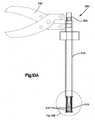
- Fig. 10Ais a front elevational view of a reduction tab removal tool that may be used in connection with the bone fixation element of Fig. 7 ;
- Fig. 10Bis a magnified front elevational view of a distal end of the reduction tab removal tool of Fig. 10A , taken from within circle 10B of Fig. 10A .
- a bone fixation element 10, 10', 10"by way of non-limiting example, a bone fixation element 10, 10', 10" for use in a posterior spinal fixation procedure to interconnect a longitudinal rod 45 with a patient's vertebra V.
- the inventionmay have other applications and uses and should not be limited to the structure or use described and illustrated.
- the same reference numeralswill be utilized throughout the application to describe similar or the same components of each of the preferred embodiments of the bone fixation elements and instruments described herein and the descriptions will focus on the specific features of the individual embodiments that distinguish the particular embodiment from the others.
- the bone fixation element 10, 10', 10"preferably includes a bone anchor 12 for securing the bone fixation element 10, 10', 10" to a patient's vertebra V, a body 20 having a rod-receiving channel 26 for receiving a longitudinal rod 45, and a locking cap 40 for securing the rod 45 in the rod-receiving channel 26 in an implanted configuration.
- the bone fixation element 10, 10', 10"also includes a pair of reduction tabs 100, 102 extending from a break-off point or region 150 to a proximal end 106 of the body 20. The reduction tabs 100, 102 facilitate or guide insertion of the longitudinal rod 45 into the rod-receiving channels 26.
- the break-off point and/or region 150facilitates removal of the reduction tabs 100, 102 from the arms 28, 30 of the body 20 after the longitudinal rod 45 has been inserted in the rod-receiving channel 26 of the bone fixation element 10, 10', 10" in a seated position.
- bone fixation element 10, 10', 10will be described as and may generally be used in the spine (for example, in the lumbar, thoracic or cervical regions), those skilled in the art will appreciate that the bone fixation element 10, 10', 10" may be used for fixation of other parts of the body such as, for example, joints, long bones or bones in the hand, face, feet, extremities, cranium, etc .
- the longitudinal rod 45may include, but not limited to, a solid rod, a non-solid rod, a flexible or dynamic rod, etc . It will be understood by one having ordinary skill in the art that the bone fixation element 10, 10', 10" is not limited to mounting to any particular type of longitudinal rod 45.
- the bone fixation element 10, 10', 10"is used generally and may include, but are not limited to, poly-axial or mono-axial pedicle screws, hooks (both mono-axial and poly-axial) including pedicle hooks, transverse process hooks, sublaminar hook, or other fasteners, clamps or implants.
- the bone fixation element 10includes the bone anchor 12 (shown as a bone screw) having an enlarged, spherically-shaped head portion 14, the locking cap 40, a sleeve 35, a bushing 36 and the body 20 (shown as a top loading body) having the proximal end 106, a distal end 24, the rod-receiving channel 26 (shown as a top loading U-shaped rod-receiving channel) defining the pair of spaced apart arms 28, 30 and the reduction tabs 100, 102 extending from the arms 28, 30.
- the locking cap 40is preferably a two-step locking cap 40, as will be described in greater detail below.
- the sleeve 35 and bushing 36are preferably slidably disposed within the body 20 and at least a portion of the bushing 36 is preferably slidably disposed within at least a portion of the sleeve 35.
- the enlarged head portion 14 of the bone anchor 12may be received within an inner spherical cavity formed in the bushing 36, which may be received within the distal end 24 of the body 20 so that the bone anchor 12 can poly-axial rotate with respect to the bushing 36, which can poly-axial rotate with respect to the body 20.
- the bone anchor 12may be formed integral with the body 20 to form a monolithic structure which is referred to as a mono-axial pedicle screw or hook.
- the body 20preferably includes a plurality of threads 121 on an inner surface of the reduction tabs 100, 102 and the arms 28, 30 for threadably receiving the locking cap 40.
- threads 121on an inner surface of the reduction tabs 100, 102 and the arms 28, 30 for threadably receiving the locking cap 40.
- other engagementsare envisioned including, but not limited to, an externally threaded body for threadably engaging an internally threaded locking cap, a cam lock, etc.
- the proximal and distal ends 106, 24 of the body 20preferably include a top opening 106a and a bottom opening 24a, respectively.
- a longitudinal bore 25extends from the top opening 106a to the bottom opening 24a.
- the enlarged head portion 14 of the bone anchor 12, the bushing 36, the sleeve 35, the locking cap 40 and at least a portion of the longitudinal rod 45are receivable in the longitudinal bore 25.
- the longitudinal bore 25preferably includes a curvate, preferably frusta-spherical, contacting surface 25a adjacent to the bottom opening 24a for contacting and receiving a curvate, preferably frusta-spherical, outer surface 36a of the bushing 36 so that the bushing 36, and hence the bone anchor 12 are polyaxially rotatable with respect to the body 20.
- the bushing 36 and the body 20are preferably configured so that the lower end of the bushing 36 sits below the distal end 24 of the body 20.
- the bushing 36enables the bone anchor 12 to rotate polyaxially with respect to the body 20 to a greater degree than polyaxially pedicle screws having a bushing completely positioned within their body.
- the combination of bushing 36 and bone anchor 12allows the bone anchor 12 to rotate to a relatively large degree.
- the locking cap 40is in the form of a two step locking cap 40 including an externally threaded outer part 42 with an internal bore 42a for threadably receiving an externally threaded inner part 44.
- a saddle 46is preferably coupled to the inner part 44 of the locking cap 40.
- the saddle 46is preferably rotatably coupled to the inner part 44 of the locking cap 40 so that the saddle 46 can contact the top surface of the longitudinal rod 45 while the locking cap 40 is being rotated.
- pedicle screwsinclude those described in International Patent Application No. PCT/US2008/070670, filed on July 21, 2008 , and published as WO 2009/015100 entitled “polyaxial Bone Fixation Element”, International Patent Application No. PCT/US2006/015692, filed on April 25, 2006 , and published as WO 2006/116437 entitled “Bone Anchor with Locking Cap and Method of Spinal Fixation”, and International Patent Application No. PCT/CH1997/00236, filed on June 16, 1997 , as published as WO 1998/052482 entitled "Device for Connecting a Longitudinal Support with a Pedicle Screw", the contents of which are hereby incorporated by reference in their entirety. It should be understood however that the present invention is not limited in use to any particular type of pedicle screw.
- the bone fixation element 10 of the first preferred embodimentmay have a low profile in an implanted configuration ( Fig. 3 ) so that the height of the bone fixation element 10 is minimized.
- the overall height of the body 20 in the implanted configurationmay be minimized so that, once engaged, the bone fixation element 10 extends a limited distance away from the vertebra V.
- the body 20 of the bone fixation element 10preferably includes a pair of reduction tabs 100, 102 extending from the pair of spaced apart arms 28, 30 to temporary extend the overall height of the bone fixation element 10 and facilitate insertion of the rod 45 into the rod-receiving channel 26 of the bone fixation element 10 during an insertion procedure.
- the reduction tabs 100, 102may have a length of about twenty millimeters (20 mm), although it is envisioned that the reduction tabs 100, 102 may be longer or shorter. Thereafter, once the longitudinal rod 45 is received within the rod-receiving channel 26 of the body 20 and the locking cap 40 is in the seated position, the reduction tabs 100, 102 may be broken off, removed and/or disposed, leaving behind the lower portion of the body 20, the locking cap 40 and the clamped rod 45 in the implanted configuration ( Fig. 3 ).
- the reduction tabs 100, 102are preferably integrally formed with the pair of spaced apart arms 28, 30 to form the body 20. Although, as will be generally appreciated by one of ordinary skill in the art, the reduction tabs 100, 102 may be coupled to the pair of arms 28, 30 by any means known in the art including, but not limited to, adhesive bonding, mechanical fastening, clamping, etc. As shown, the reduction tabs 100, 102 generally define the rod-receiving channel 26 formed in the body 20 between the break-off region 150 and the proximal end 106.
- the reduction tabs 100, 102preferably includes an inner surface 108 and an outer surface 110. The inner surface 108 of the reduction tabs 100, 102 preferably includes threads 121.
- the threads 121begin at or near the proximal end 106 and extend substantially the entire length of the reduction tabs 100, 102.
- the threads 121preferably have a thread profile that matches the thread profile of the threads 21 formed on the inner surface of the lower portion of the body 20 and the thread profile on the outer surface of the locking cap 40. More preferably, as will be described in greater detail below, the threads on the inner surface of the body 20 and the outer surface of the locking cap 40 have a negative thread profile.
- the break-off point(s) or region(s) 150generally separates the lower portion of the body 20 and the reduction tabs 100, 102. More preferably the reduction tabs 100, 102 and the pair of spaced apart arms 28, 30 are preferably integrally formed as a portion of the body 20.
- the break-off points or regions 150are preferably an area of weakness formed at a distal end of the reduction tabs 100, 102 so that the reduction tabs 100, 102 are breakable from the spaced apart arms 28, 30 when subjected to high stresses, such as by stresses induced by the surgeon in order to break or dislodge the reduction tabs 100, 102 from the spaced apart arms 28, 30.
- the reduction tabs 100, 102are preferably designed to break off such that they can be, partially or completely, removed from the patient's body after the longitudinal rod 45 has been seated and secured within the rod-receiving channel 26 in the implanted configuration.
- the reduction tabs 100, 102may be severed from the spaced-apart arms 28, 30 via pliers, a break-off tool, by grasping and applying forces to the proximal end 106, by hand or in numerous other ways that permit application of rupturing forces at the break-off points or regions 150.
- the break-off points or regions 150 of the first preferred embodimentare configured as a pair of grooves 152a, 152b.
- the break-off points or regions 150may be configured as a single weakened region, thinned-out area, etc.
- the body 20includes the pair of break-off grooves 152a, 152b including an outer break-off groove 152b formed along the outer surface 110 of the reduction tabs 100, 102 and an inner break-off groove 152a formed along the inner surface 108 of the reduction tabs 100, 102.
- the outer break-off groove 152bis preferably located distally of the inner break-off groove 152a, but is not so limited and the outer break-off groove 152b may be located proximally in comparison to the inner break-off groove 152a or the inner and outer break-off grooves 152a, 152b may be formed generally at the same level along the length of the body 20.
- a fracture line 151 location and configurationcan be influenced.
- the shape and location of the inner and outer break-off grooves 152a, 152b of the first preferred embodimentare arranged to limit any potentially sharp edges as a result of the reduction tabs 100, 102 being broken or ruptured from the body 20.
- the bone fixation element 10 of the first preferred embodimentis assembled by inserting the enlarged head portion 14 of the bone anchor 12 into the inner, frusta-spherically-shaped cavity of the bushing 36.
- the bushing/screw assemblyis then inserted into the body 20 through the top opening 106a until the frusta-spherical outer surface of the bushing 36 contacts the frusta-spherical inner surface 25a of the body 20 adjacent to the distal end 24.
- the sleeve 35is then inserted into the body 20 through the top opening 106a so that the sleeve 35 is positioned on top of the bushing 36.
- the top surface of the sleeve 35preferably includes a seat 35a for receiving the longitudinal rod 45 in the seated position.
- the body/sleeve/bushing/bone anchor - assemblymay be provided pre-assembled to surgeons so that, in use, a surgeon can implant the assembly into the patient's vertebra V.
- the bone anchor 12may be secured to a patient's bone, preferably the patient's vertebra V, by driving the bone anchor 12 with a screwdriver or other similar screw driving device.
- the surgeonis able to polyaxially rotate the body 20 with respect to the bone anchor 12 and with respect to the engaged bone so that the longiditudinal rod 45 can be inserted into the rod-receiving channels 126 defined by the reduction tabs 100, 102 of adjacent bone fixation elements 10.
- the longitudinal rod 45may or may not be seated within the rod-receiving channel 26 of the bone fixation element 20.
- the locking cap 40is threadably coupled along the inner surface 108 of the reduction tabs 100, 102. Thereafter, rotation of the locking cap 40 causes the bottom surface of the locking cap 40 to contact the top surface of the longitudinal rod 45, which is located within the rod receiving channel 126, thereby urging the longitudinal rod 45 towards the bottom opening 24a of the body 20 and into the rod-receiving channel 26 formed in the body 20, as generally depicted in Figs. 1 and 2
- the longitudinal rod 45may still be movable with respect to the body 20 so that distraction and/or compression of the patient's adjacent vertebrae V may be accomplished, typically by applying distraction and/or compression to the bone anchors 12.
- the inner part 44 of the locking cap 40is rotated with respect to the outer part 42 of the locking cap 40, urging the inner part 44 toward the distal end 24. Rotation of the inner part 44 of the locking cap 40 causes the inner part 44 of the locking cap 40 to urge the saddle 46 into contact with the longitudinal rod 45 and against the sleeve 35, which in turn fixes the position of the longitudinal rod 45 with respect to the body 20.
- the reduction tabs 100, 102are preferably removed by breaking the reduction tabs 100, 102 at the break-off points or regions 150, thereby leaving the lower portion of the body 20, the locking cap 40 and the clamped longitudinal rod 45 within the patient's body.
- the bone fixation element 10may be manufactured from any biocompatible material such as, but not limited to, titanium, titanium alloys, stainless steel, cobalt chromium, Nitinol, etc . Moreover, as will be generally understood by one of ordinary skill in the art, the bone fixation element 10 may be provided in any number of sizes and configurations depending on the size and configuration of the bone anchor 12, longitudinal rod 45 and/or on the type and location of the surgery being performed.
- the threads 21, 121 formed on the inner surface of the body 20 and the threads formed on the outer surface of the locking cap 40preferably incorporate a negative thread profile. That is, the load flank and stab flank of the threads 21, 121 and the outer surface of the locking cap 40 are angled downwards with respect to a plane perpendicular to the longitudinal axis 20a of the body 20 and the locking cap 40.
- the threads 21, 121form an angle of negative ten degrees (-10°) with respect to a plane perpendicular to the longitudinal axis 20a of the body 20.
- the threads 21, 121are not limited to the negative ten degree (-10°) angles and may form nearly any angle that permits engagement and driving of the locking cap 40 into the body 20.
- the negative thread profileis preferred to limit splaying of the arms 28, 30 and reduction tabs 100, 102 as the locking cap 40 is being urged downwardly toward the distal end 24.
- a second preferred embodiment of the bone fixation element 10'is substantially similar to bone fixation element 10 of the first preferred embodiment and like elements are identified using like reference numerals with a prime symbol (') to indicate the second preferred embodiment.
- the bone fixation element 10' of the second preferred embodimentincludes a proximal end cap 200'.
- the proximal end cap 200'connects the reduction tabs 100', 102' adjacent to the proximal end 106' of the body 20'.
- the cap 200'preferably includes an internal bore 202' that enables the locking cap 40' to pass therethrough.
- the cap 200'is preferably integrally formed with the reduction tabs 100', 102'.
- the cap 200'may be operatively connected to the reduction tabs 1.00', 102' by nearly any connection mechanism including, but not limited to, adhesive, bonding, mechanical fasteners, etc .
- the reduction tabs 100', 102'By providing the cap 200', splaying of the reduction tabs 100', 102', as a consequence of the locking cap 40' being rotated toward the distal end 24 to urge the longitudinal rod 45 into the rod-receiving channel 26' is preferably limited, thereby enabling the length of the reduction tabs 100', 102' to be increased.
- Overall lengthening of the reduction tabs 100', 102'may be beneficial for lumbar applications and in enabling the reduction tabs 100', 102' to be used in minimally invasive procedures for guiding a longitudinal rod 45 into the rod-receiving channel 26' of the bone fixation element 10', as will be described in greater detail below.
- the reduction tabs 100', 102'may have a length of about one hundred millimeters (100 mm), although it is envisioned that the reduction tabs 100', 102' may be longer or shorter to accommodate various patient anatomy.
- the cap 200' of the second preferred embodimentincludes a distal shoulder 204' and a proximal shoulder 206'.
- the distal and proximal shoulders 204', 206'enables the user to attach one or more instruments to the bone fixation element 10' to improve control of the bone fixation element 10'.
- the shoulders 204', 206'enable the user to attach a distraction/compression instrument or forceps to perform rod reduction, a counter-torque device, etc.
- the preferred cap 200'also provides the bone fixation element 10' with a holding mechanism to facilitate percutaneous control of the rod-receiving channel 26', as will be described in greater detail below.
- a third preferred embodiment of the bone fixation element 10"is substantially similar to bone fixation element 10' of the second preferred embodiment and like elements are identified using like reference numerals with a double-prime symbol (") to indicate the third preferred embodiment.
- the cap 200"includes a drive surface 210" for receiving a corresponding tip (not shown) formed on a drive tool (not shown).
- the drive surface 210"may be in the form of an external hex for engaging a corresponding internal hex so that the user may apply a counter torque so that during final tightening of the locking cap 40", a counter-acting torque may be applied.
- the drive surface 210"may have any form now or hereafter known including, but not limited to, an internal hexagon, a star drive pattern, a Phillips head pattern, a slot for a screw driver, a threading for a correspondingly threaded post, etc.
- the break-off points or regions 150' of bone fixation element 10' of the second preferred embodimentmay be configured as a pair of connection points 252', 254' on either side of a through slot 256'.
- the proximal end cap 200'may increase the strength and stability of the break-off region 150' and increase the force required to remove the reduction tabs 100', 102'.
- the break-off point or region 150'includes a through slot 256' for mating with a reduction tab removal instrument 300.
- the reduction tab removal instrument 300preferably includes an outer shaft 310 including a plurality of expandable prongs 315 on a distal end thereof, an inner shaft 320 slidably disposed within the outer shaft 310 and a handle 330 operatively coupled to the outer and inner shafts 310, 320 for operatively moving the inner shaft 320 with respect to the outer shaft 310.
- the expandable prongs 315preferably include a wedge-shaped portion 317 for contacting and/or engaging the through slot 256 formed in the break-off points or regions 150.
- the outer and inner shafts 310, 320 of the reduction tab removal instrument 300are inserted into the rod-receiving channel 126'.
- the wedge-shaped portion 317 formed on the outer surface of the outer shaft 310is placed into operative association with the through slot 256' of the break-off points or regions 150'.
- an instrumentmay be rotated so that wedge-shaped portions may shear the reduction tabs 100', 102' from the bone fixation element 10'.
- the bone fixation elements 10'are preferably implanted into the patent's vertebra V via a minimally invasive surgical technique.
- the bone fixation element 10'may be inserted via a cannula. Once implanted, the cannula may be removed, leaving behind the bone fixation elements 10' including reduction tabs 100', 102'. Thereafter, the user may align the rod-receiving channels 26' of the bone fixation elements 10' so that the longitudinal rod 45 may be guided into place.
- a rod-reducing instrument(not shown) may be operatively coupled to the reduction tabs 100', 102', and in particular to the cap 200'.
- the rod-reducing instrumentmay be used to reduce or seat the rod 45 into the rod-receiving channel 26' of the bone fixation element 10'.
- the locking cap 40'is inserted and rotated into place until the rod 45 is secured within the rod-receiving channel 26'.
- the reduction tab removal instrument 300may then be inserted between the reduction tabs 100', 102' and activated to sever the reduction tabs 100', 102' from the bone fixation element 10'. Lastly, the reduction tabs 100', 102' are removed and the incision is closed.
- the bone fixation elements 10may be inserted into the patient's adjacent vertebrae V by forming an incision in the patient, positioning K-wires into the adjacent vertebra V to define trajectory, sequentially engaging a screwdriver (not shown) with the heads 14 and screwing the bone anchors 12 into the adjacent vertebra V along the K-wires and aligning the rod receiving channels 26 of adjacent bone fixation elements 10.
- the rod receiving channels 26preferably extend out of the incision and are utilized to guide the longitudinal rod 45 into the lower portion of the body 20.
- a reduction toolmay be utilized to reduce the rod 45 into the lower portion of the body 20 or locking caps 40 may be engaged with the inner threads 121 and driven toward the distal end 24 to move the rod 45 from the insertion position to the seated position.
- the locking caps 40are urged toward the distal end 24 at least until the bushing 36 engages and locks the position of the bone anchors 12 relative to the bodies 20.
- One of the inner parts 44is driven toward the distal end 24 to lock the rod 45 relative to the body 20 and the adjacent bone fixation element 10 is not final tightened such that compression or distraction may be performed on the adjacent vertebra.
- the second inner part 44is driven toward the distal end 24 to fix the rod 45 relative to both adjacent fixation elements.
- the reduction tabs 100, 102are broken away from the lower portion of the body 20 at the break-off regions 150 and are removed from the patient's body. The procedure may be performed in a minimally invasive manner using percutaneous or mini-open incisions to receive a single bone fixation element 10 through the percutaneous incision or at least a pair of bone fixation elements 10 through the mini-open incision.
- any or all of the components described hereinmay be provided in sets or kits so that the surgeon may select various combinations of components to perform a fixation procedure and create a fixation system which is configured specifically for the particular needs/anatomy of a patient. It should be noted that one or more of each component may be provided in a kit or set. In some kits or sets, the same device may be provided in different shapes and/or sizes.
Landscapes
- Health & Medical Sciences (AREA)
- Orthopedic Medicine & Surgery (AREA)
- Surgery (AREA)
- Life Sciences & Earth Sciences (AREA)
- Neurology (AREA)
- Medical Informatics (AREA)
- Biomedical Technology (AREA)
- Heart & Thoracic Surgery (AREA)
- Engineering & Computer Science (AREA)
- Molecular Biology (AREA)
- Animal Behavior & Ethology (AREA)
- General Health & Medical Sciences (AREA)
- Public Health (AREA)
- Veterinary Medicine (AREA)
- Nuclear Medicine, Radiotherapy & Molecular Imaging (AREA)
- Surgical Instruments (AREA)
- Prostheses (AREA)
Description
- The invention relates to a bone fixation element, according to the preamble of claim 1.
- It is often necessary due to various spinal disorders to surgically correct and stabilize spinal curvatures, or to facilitate spinal fusion through an open approach or through a minimally invasive approach. Numerous systems for treating spinal disorders have been disclosed. One known method involves a pair of elongated members, typically rods, longitudinally fixed to the posterior spine on either side of spinous processes of the vertebral column. Each rod is attached to various vertebrae along the length of the spine by engaging bone fixation elements to the vertebra and fixing a rod to the bone fixation elements. The bone fixation elements commonly include a U-shaped rod-receiving channel for receiving the rod therein. Moreover, the rod-receiving channel often interacts with a locking cap to clamp and fix the position of the rod with respect to the bone fixation element.
- Surgeons may have difficulty aligning the rod(s) within the rod-receiving channels formed in the body of the bone fixation elements. For example, the body of the bone fixation elements may be out of vertical and/or horizontal alignment with one another due to the curvature of the spine or the size and shape of each vertebra.
- Thus, it is desirable to construct an apparatus to facilitate insertion of the longitudinal rods into the rod-receiving channels formed in the bone fixation elements.
- From
US 2006/036252 [Baynham et al. ] a polyaxial screw is known based on the preamble of claim 1. - From
US 2005/273101 [Schumacher ] a bone screw and osteosynthesis device is known. FromUS 2006/025771 [Jackson ] a helical reverse angle guide and advancement structure with break-off extensions is known. FromUS 2006/058794 [Jackson ] a helical guide and advancement flange with break-off extension is known.DE 4436262 [Schäfer ] discloses a reposition screw, in particular for vertebrae and fromUS 2007/0167948 [Abdou ] devices and methods for inter-vertebral orthopedic devices placement are known. - A further anchoring element comprising a bone screw and a receiving member for connecting the bone screw to a rod is known from
US 2002/143341 [Biedermann et al. ]. - A preferred embodiment of the present invention is directed to a bone fixation element for use in a posterior spinal fixation procedure to interconnect a longitudinal rod with a patient's vertebral body. The bone fixation element includes a body having a pair of spaced apart arms defining a rod-receiving channel and a pair of reduction tabs operatively coupled to the spaced apart arms to facilitate insertion of the longitudinal rod into the rod-receiving channels. In order to facilitate vertical reduction of the longitudinal rod into the rod-receiving channel, the bone fixation element includes a pair of reduction tabs extending therefrom to temporarily extend the overall height of the bone fixation element. The reduction tabs define a rod-receiving channel that aligns with and/or temporarily extends the rod-receiving channel formed in the bone fixation element.
- The reduction tabs are preferably integrally formed with the bone fixation element. The reduction tabs preferably include a break-off point and/or region so that after the longitudinal rod has been inserted into the rod-receiving channel of the bone fixation element, the reduction tabs can be removed leaving in place the bone fixation element and longitudinal rod. The break-off points or regions are configured as an area of weakness formed in the reduction tabs so that the reduction tabs will break or rupture when subjected to high stresses, such as by stresses induced by the surgeon in order to break or sever the reduction tabs from the bone fixation element so that the reduction tabs can be removed from the patient's body after the longitudinal rod has been seated and secured within the rod-receiving channel.
- The break-off points or regions may be configured as a groove. Preferably, each of the reduction tabs includes a pair of break-off grooves, one formed along the outer surface of the reduction tabs and one formed along the inner surface of the reduction tabs. The outer break-off groove is preferably located distally of the inner break-off groove. By incorporating inner and outer break-off grooves, the fracture line and surface may be controlled to substantially reduce potentially sharp edges as a result of the reduction tabs being broken or ruptured from the body.
- Alternatively, the break-off points or regions may be configured as a pair of connection points on either side of a through slot, wherein the through slot extends from an outer surface of the tabs to an inner surface of the tabs.
- The reduction tabs may also include a cap for coupling to a proximal end of the reduction tabs. The cap preferably includes at least one shoulder to enable a user to attach one or more instruments to the bone fixation element. The cap may also include a drive surface for receiving a corresponding tip formed on a drive tool for applying a counter torque force.
- The bone fixation element including reduction tabs may be provided as a part of a system including a reduction tab removal instrument for severing the reduction tabs from the bone fixation element after the longitudinal rod has been seated within the rod-receiving channel of the bone fixation element. The reduction tab removal instrument may include an outer shaft including a plurality of expandable prongs on a distal end thereof, an inner shaft slidably disposed within the outer shaft and a handle operatively coupled to the outer and inner shafts for operatively moving the inner shaft with respect to the outer shaft such that movement of the inner shaft with respect to the outer shaft causes the plurality of expandable prongs to radially expand. The expandable prongs may include a wedge shaped portion for contacting the through slot formed in the break-off region.
- The inner surface of the reduction tabs and the inner surface of the spaced apart arms preferably include a plurality of threads for engaging an externally threaded locking cap. More preferably, the threads have a negative thread profile to limit splaying.
- The foregoing summary, as well as the following detailed description of the preferred embodiments of the application, will be better understood when read in conjunction with the appended drawings. For the purposes of illustrating the preferred bone fixation elements and surgical method for inserting the bone fixation elements of the present application, there are shown in the drawings preferred embodiments. It should be understood, however, that the application is not limited to the precise arrangement and instrumentalities shown. In the drawings:
Fig. 1 is a cross-sectional view of a first preferred embodiment of a bone fixation element of the present invention, with a longitudinal rod positioned in a rod-receiving channel of the bone fixation element in an insertion position;Fig. 2 is a cross-sectional view of the bone fixation element shown inFig. 1 , the longitudinal rod located in a seated position;Fig. 3 is a cross-sectional view of the bone fixation element shown inFig. 1 , with reduction tabs of the bone fixation element being removed from a body in an implanted configuration and the longitudinal rod located in the seated position;Fig. 4 is a cross-sectional view of the body of the bone fixation element ofFig. 1 ;Fig. 5 is a detailed, cross-sectional view of a break-off region of the body ofFig. 4 , taken from within circle 5 ofFig. 4 ;Fig. 6 is a detailed, cross-sectional view of a thread profile on an inner surface of the body ofFig. 4 , the thread profile taken from within circle 6 ofFig. 4 .Fig. 7 is a front elevational view of a second preferred embodiment of a bone fixation element of the present invention with a longitudinal rod positioned in the seated position and a first preferred cap mounted to a proximal end;Fig. 8 is a front elevational view of a third preferred embodiment of a bone fixation element of the present invention with a longitudinal rod positioned in the seated position and a second preferred cap mounted to a proximal end;Fig. 9 is a magnified, side perspective view of the bone fixation element ofFig. 7 with an exemplary break-off region;Fig. 10A is a front elevational view of a reduction tab removal tool that may be used in connection with the bone fixation element ofFig. 7 ; andFig. 10B is a magnified front elevational view of a distal end of the reduction tab removal tool ofFig. 10A , taken from within circle 10B ofFig. 10A .- Certain terminology is used in the following description for convenience only and is not limiting. The words "right", "left", "lower" and "upper" designate directions in the drawings to which reference is made. The words "inwardly" and "outwardly" refer to directions toward and away from, respectively, the geometric center of the bone fixation element, instruments and designated parts thereof. The words, "anterior", "posterior", "superior", "inferior", "medial", "lateral" and related words and/or phrases designate preferred positions and orientations in the human body to which reference is made and are not meant to be limiting. The terminology includes the above-listed words, derivatives thereof and words of similar import.
- Certain exemplary embodiments of the invention will now be described with reference to the drawings. In general, such embodiments relate to a
bone fixation element bone fixation element longitudinal rod 45 with a patient's vertebra V. The invention may have other applications and uses and should not be limited to the structure or use described and illustrated. The same reference numerals will be utilized throughout the application to describe similar or the same components of each of the preferred embodiments of the bone fixation elements and instruments described herein and the descriptions will focus on the specific features of the individual embodiments that distinguish the particular embodiment from the others. - As will be described in greater detail below, the
bone fixation element bone anchor 12 for securing thebone fixation element body 20 having a rod-receivingchannel 26 for receiving alongitudinal rod 45, and a lockingcap 40 for securing therod 45 in the rod-receivingchannel 26 in an implanted configuration. Thebone fixation element reduction tabs region 150 to aproximal end 106 of thebody 20. Thereduction tabs longitudinal rod 45 into the rod-receivingchannels 26. The break-off point and/orregion 150 facilitates removal of thereduction tabs arms body 20 after thelongitudinal rod 45 has been inserted in the rod-receivingchannel 26 of thebone fixation element - While the
bone fixation element bone fixation element - As generally understood by one of ordinary skill in the art, the
longitudinal rod 45 may include, but not limited to, a solid rod, a non-solid rod, a flexible or dynamic rod,etc. It will be understood by one having ordinary skill in the art that thebone fixation element longitudinal rod 45. - As generally understood by one of ordinary skill in the art, the
bone fixation element - Referring to
Figs. 1-3 , in the first preferred embodiment, thebone fixation element 10 includes the bone anchor 12 (shown as a bone screw) having an enlarged, spherically-shapedhead portion 14, the lockingcap 40, asleeve 35, abushing 36 and the body 20 (shown as a top loading body) having theproximal end 106, adistal end 24, the rod-receiving channel 26 (shown as a top loading U-shaped rod-receiving channel) defining the pair of spaced apartarms reduction tabs arms cap 40 is preferably a two-step locking cap 40, as will be described in greater detail below. Thesleeve 35 andbushing 36 are preferably slidably disposed within thebody 20 and at least a portion of thebushing 36 is preferably slidably disposed within at least a portion of thesleeve 35. In use, theenlarged head portion 14 of thebone anchor 12 may be received within an inner spherical cavity formed in thebushing 36, which may be received within thedistal end 24 of thebody 20 so that thebone anchor 12 can poly-axial rotate with respect to thebushing 36, which can poly-axial rotate with respect to thebody 20. Alternatively, thebone anchor 12 may be formed integral with thebody 20 to form a monolithic structure which is referred to as a mono-axial pedicle screw or hook. - The
body 20 preferably includes a plurality ofthreads 121 on an inner surface of thereduction tabs arms cap 40. Although, as will be generally appreciated by one of ordinary skill in the art, other engagements are envisioned including, but not limited to, an externally threaded body for threadably engaging an internally threaded locking cap, a cam lock,etc. The proximal anddistal ends body 20 preferably include atop opening 106a and abottom opening 24a, respectively. Alongitudinal bore 25 extends from thetop opening 106a to thebottom opening 24a. Theenlarged head portion 14 of thebone anchor 12, thebushing 36, thesleeve 35, the lockingcap 40 and at least a portion of thelongitudinal rod 45 are receivable in thelongitudinal bore 25. Thelongitudinal bore 25 preferably includes a curvate, preferably frusta-spherical, contactingsurface 25a adjacent to thebottom opening 24a for contacting and receiving a curvate, preferably frusta-spherical, outer surface 36a of thebushing 36 so that thebushing 36, and hence thebone anchor 12 are polyaxially rotatable with respect to thebody 20. - The
bushing 36 and thebody 20 are preferably configured so that the lower end of thebushing 36 sits below thedistal end 24 of thebody 20. As a result of the lower end of thebushing 36 sitting lower than thedistal end 24 of thebody 20, thebushing 36 enables thebone anchor 12 to rotate polyaxially with respect to thebody 20 to a greater degree than polyaxially pedicle screws having a bushing completely positioned within their body. In addition, since theenlarged head portion 14 of thebone anchor 12 is able to rotate with respect to thebushing 36 and thebushing 36 is able to rotate with respect to thebody 20, the combination ofbushing 36 andbone anchor 12 allows thebone anchor 12 to rotate to a relatively large degree. - The locking
cap 40 is in the form of a twostep locking cap 40 including an externally threadedouter part 42 with aninternal bore 42a for threadably receiving an externally threadedinner part 44. Asaddle 46 is preferably coupled to theinner part 44 of the lockingcap 40. Thesaddle 46 is preferably rotatably coupled to theinner part 44 of the lockingcap 40 so that thesaddle 46 can contact the top surface of thelongitudinal rod 45 while the lockingcap 40 is being rotated. - Exemplary embodiments of pedicle screws include those described in International Patent Application No.
PCT/US2008/070670, filed on July 21, 2008 , and published asWO 2009/015100 entitled "polyaxial Bone Fixation Element", International Patent Application No.PCT/US2006/015692, filed on April 25, 2006 , and published asWO 2006/116437 entitled "Bone Anchor with Locking Cap and Method of Spinal Fixation", and International Patent Application No.PCT/CH1997/00236, filed on June 16, 1997 WO 1998/052482 entitled "Device for Connecting a Longitudinal Support with a Pedicle Screw", the contents of which are hereby incorporated by reference in their entirety. It should be understood however that the present invention is not limited in use to any particular type of pedicle screw. - Referring to
Figs. 1-4 , thebone fixation element 10 of the first preferred embodiment may have a low profile in an implanted configuration (Fig. 3 ) so that the height of thebone fixation element 10 is minimized. The overall height of thebody 20 in the implanted configuration may be minimized so that, once engaged, thebone fixation element 10 extends a limited distance away from the vertebra V. Thebody 20 of thebone fixation element 10 preferably includes a pair ofreduction tabs arms bone fixation element 10 and facilitate insertion of therod 45 into the rod-receivingchannel 26 of thebone fixation element 10 during an insertion procedure. For example, thereduction tabs reduction tabs longitudinal rod 45 is received within the rod-receivingchannel 26 of thebody 20 and the lockingcap 40 is in the seated position, thereduction tabs body 20, the lockingcap 40 and the clampedrod 45 in the implanted configuration (Fig. 3 ). - The
reduction tabs arms body 20. Although, as will be generally appreciated by one of ordinary skill in the art, thereduction tabs arms reduction tabs channel 26 formed in thebody 20 between the break-offregion 150 and theproximal end 106. Thereduction tabs inner surface 108 and anouter surface 110. Theinner surface 108 of thereduction tabs threads 121. More preferably, thethreads 121 begin at or near theproximal end 106 and extend substantially the entire length of thereduction tabs threads 121 preferably have a thread profile that matches the thread profile of thethreads 21 formed on the inner surface of the lower portion of thebody 20 and the thread profile on the outer surface of the lockingcap 40. More preferably, as will be described in greater detail below, the threads on the inner surface of thebody 20 and the outer surface of the lockingcap 40 have a negative thread profile. - The break-off point(s) or region(s) 150 generally separates the lower portion of the
body 20 and thereduction tabs reduction tabs arms body 20. The break-off points orregions 150 are preferably an area of weakness formed at a distal end of thereduction tabs reduction tabs arms reduction tabs arms reduction tabs longitudinal rod 45 has been seated and secured within the rod-receivingchannel 26 in the implanted configuration. Thereduction tabs arms proximal end 106, by hand or in numerous other ways that permit application of rupturing forces at the break-off points orregions 150. - Referring to
Figs. 4 and 5 , the break-off points orregions 150 of the first preferred embodiment are configured as a pair ofgrooves regions 150 may be configured as a single weakened region, thinned-out area,etc. More preferably, thebody 20 includes the pair of break-offgrooves groove 152b formed along theouter surface 110 of thereduction tabs groove 152a formed along theinner surface 108 of thereduction tabs groove 152b is preferably located distally of the inner break-offgroove 152a, but is not so limited and the outer break-offgroove 152b may be located proximally in comparison to the inner break-offgroove 152a or the inner and outer break-offgrooves body 20. By incorporating inner and outer break-offgrooves fracture line 151 location and configuration can be influenced. Specifically, the shape and location of the inner and outer break-offgrooves reduction tabs body 20. - The
bone fixation element 10 of the first preferred embodiment is assembled by inserting theenlarged head portion 14 of thebone anchor 12 into the inner, frusta-spherically-shaped cavity of thebushing 36. The bushing/screw assembly is then inserted into thebody 20 through thetop opening 106a until the frusta-spherical outer surface of thebushing 36 contacts the frusta-sphericalinner surface 25a of thebody 20 adjacent to thedistal end 24. Thesleeve 35 is then inserted into thebody 20 through thetop opening 106a so that thesleeve 35 is positioned on top of thebushing 36. The top surface of thesleeve 35 preferably includes a seat 35a for receiving thelongitudinal rod 45 in the seated position. The body/sleeve/bushing/bone anchor - assembly may be provided pre-assembled to surgeons so that, in use, a surgeon can implant the assembly into the patient's vertebra V. - In use, the
bone anchor 12 may be secured to a patient's bone, preferably the patient's vertebra V, by driving thebone anchor 12 with a screwdriver or other similar screw driving device. With thebone anchor 12 engaged to the patient's bone, the surgeon is able to polyaxially rotate thebody 20 with respect to thebone anchor 12 and with respect to the engaged bone so that thelongiditudinal rod 45 can be inserted into the rod-receivingchannels 126 defined by thereduction tabs bone fixation elements 10. Thelongitudinal rod 45 may or may not be seated within the rod-receivingchannel 26 of thebone fixation element 20. - Once the
longitudinal rod 45 is received within the rod-receivingchannel 126, the lockingcap 40 is threadably coupled along theinner surface 108 of thereduction tabs cap 40 causes the bottom surface of the lockingcap 40 to contact the top surface of thelongitudinal rod 45, which is located within therod receiving channel 126, thereby urging thelongitudinal rod 45 towards thebottom opening 24a of thebody 20 and into the rod-receivingchannel 26 formed in thebody 20, as generally depicted inFigs. 1 and2 - Continued rotation of the locking
cap 40 toward thedistal end 24 urges the lockingcap 40 into thesleeve 35, thereby urging thesleeve 35 downwards into further contact with thebushing 36. Downward movement of thesleeve 35 causes thebushing 36 to radially compress against theenlarged head portion 14 of thebone anchor 12, which in turn, fixes the position of thebone anchor 12 with respect to thebody 20. - The
longitudinal rod 45 may still be movable with respect to thebody 20 so that distraction and/or compression of the patient's adjacent vertebrae V may be accomplished, typically by applying distraction and/or compression to the bone anchors 12. Once the desired position of the adjacent vertebrae V is accomplished, theinner part 44 of the lockingcap 40 is rotated with respect to theouter part 42 of the lockingcap 40, urging theinner part 44 toward thedistal end 24. Rotation of theinner part 44 of the lockingcap 40 causes theinner part 44 of the lockingcap 40 to urge thesaddle 46 into contact with thelongitudinal rod 45 and against thesleeve 35, which in turn fixes the position of thelongitudinal rod 45 with respect to thebody 20. - As generally shown in
Fig. 3 , once thelongitudinal rod 45 is secured within the rod-receivingchannel 26 of thebone fixation element 10, thereduction tabs reduction tabs regions 150, thereby leaving the lower portion of thebody 20, the lockingcap 40 and the clampedlongitudinal rod 45 within the patient's body. - The
bone fixation element 10 may be manufactured from any biocompatible material such as, but not limited to, titanium, titanium alloys, stainless steel, cobalt chromium, Nitinol,etc. Moreover, as will be generally understood by one of ordinary skill in the art, thebone fixation element 10 may be provided in any number of sizes and configurations depending on the size and configuration of thebone anchor 12,longitudinal rod 45 and/or on the type and location of the surgery being performed. - Referring to
Fig. 6 , thethreads body 20 and the threads formed on the outer surface of the lockingcap 40 preferably incorporate a negative thread profile. That is, the load flank and stab flank of thethreads cap 40 are angled downwards with respect to a plane perpendicular to thelongitudinal axis 20a of thebody 20 and the lockingcap 40. In the first preferred embodiment, thethreads longitudinal axis 20a of thebody 20. Thethreads cap 40 into thebody 20. The negative thread profile is preferred to limit splaying of thearms reduction tabs cap 40 is being urged downwardly toward thedistal end 24. - Referring to
Fig. 7 , a second preferred embodiment of the bone fixation element 10' is substantially similar tobone fixation element 10 of the first preferred embodiment and like elements are identified using like reference numerals with a prime symbol (') to indicate the second preferred embodiment. The bone fixation element 10' of the second preferred embodiment includes a proximal end cap 200'. The proximal end cap 200' connects the reduction tabs 100', 102' adjacent to the proximal end 106' of the body 20'. The cap 200' preferably includes an internal bore 202' that enables the locking cap 40' to pass therethrough. The cap 200' is preferably integrally formed with the reduction tabs 100', 102'. Alternatively, the cap 200' may be operatively connected to the reduction tabs 1.00', 102' by nearly any connection mechanism including, but not limited to, adhesive, bonding, mechanical fasteners,etc. - By providing the cap 200', splaying of the reduction tabs 100', 102', as a consequence of the locking cap 40' being rotated toward the
distal end 24 to urge thelongitudinal rod 45 into the rod-receiving channel 26' is preferably limited, thereby enabling the length of the reduction tabs 100', 102' to be increased. Overall lengthening of the reduction tabs 100', 102' may be beneficial for lumbar applications and in enabling the reduction tabs 100', 102' to be used in minimally invasive procedures for guiding alongitudinal rod 45 into the rod-receiving channel 26' of the bone fixation element 10', as will be described in greater detail below. For example, the reduction tabs 100', 102' may have a length of about one hundred millimeters (100 mm), although it is envisioned that the reduction tabs 100', 102' may be longer or shorter to accommodate various patient anatomy. - The cap 200' of the second preferred embodiment includes a distal shoulder 204' and a proximal shoulder 206'. The distal and proximal shoulders 204', 206' enables the user to attach one or more instruments to the bone fixation element 10' to improve control of the bone fixation element 10'. For example, the shoulders 204', 206' enable the user to attach a distraction/compression instrument or forceps to perform rod reduction, a counter-torque device,etc.
- The preferred cap 200' also provides the bone fixation element 10' with a holding mechanism to facilitate percutaneous control of the rod-receiving channel 26', as will be described in greater detail below.
- Referring to
Fig. 8 , a third preferred embodiment of thebone fixation element 10" is substantially similar to bone fixation element 10' of the second preferred embodiment and like elements are identified using like reference numerals with a double-prime symbol (") to indicate the third preferred embodiment. In the third preferred embodiment, thecap 200" includes adrive surface 210" for receiving a corresponding tip (not shown) formed on a drive tool (not shown). For example, thedrive surface 210" may be in the form of an external hex for engaging a corresponding internal hex so that the user may apply a counter torque so that during final tightening of the lockingcap 40", a counter-acting torque may be applied. Thedrive surface 210" may have any form now or hereafter known including, but not limited to, an internal hexagon, a star drive pattern, a Phillips head pattern, a slot for a screw driver, a threading for a correspondingly threaded post,etc. - Referring to
Figs. 9-10B , the break-off points or regions 150' of bone fixation element 10' of the second preferred embodiment may be configured as a pair of connection points 252', 254' on either side of a through slot 256'. In the second preferred embodiment, the proximal end cap 200' may increase the strength and stability of the break-off region 150' and increase the force required to remove the reduction tabs 100', 102'. Thus, to facilitate removal of the tabs 100', 102' from the bone fixation element 10' after therod 45 is seated within the rod-receiving channel 26' of the bone fixation element 10', the break-off point or region 150' includes a through slot 256' for mating with a reductiontab removal instrument 300. The reductiontab removal instrument 300 preferably includes anouter shaft 310 including a plurality ofexpandable prongs 315 on a distal end thereof, aninner shaft 320 slidably disposed within theouter shaft 310 and ahandle 330 operatively coupled to the outer andinner shafts inner shaft 320 with respect to theouter shaft 310. Theexpandable prongs 315 preferably include a wedge-shapedportion 317 for contacting and/or engaging the throughslot 256 formed in the break-off points orregions 150. - In use, after the
longitudinal rod 45 has been properly secured within the rod-receiving channel 26' of the bone fixation element 10' via the locking cap 40', the outer andinner shafts tab removal instrument 300 are inserted into the rod-receiving channel 126'. Preferably, the wedge-shapedportion 317 formed on the outer surface of theouter shaft 310 is placed into operative association with the through slot 256' of the break-off points or regions 150'. Thereafter, squeezing of thehandles 330 causes theinner shaft 320 to move distally with respect to theouter shaft 310, which in turn causes theexpandable prongs 315 formed on the distal end of theouter shaft 310 to radially expand resulting in the wedge shapedportions 317 pushing into or onto the through slots 256' resulting in the breaking and removal of the reduction tabs 100', 102'. - It should be noted that other instruments may be used to facilitate breaking and removal of the reduction tabs 100', 102'. For example, an instrument may be rotated so that wedge-shaped portions may shear the reduction tabs 100', 102' from the bone fixation element 10'.
- In use, the bone fixation elements 10' are preferably implanted into the patent's vertebra V via a minimally invasive surgical technique. For example, the bone fixation element 10' may be inserted via a cannula. Once implanted, the cannula may be removed, leaving behind the bone fixation elements 10' including reduction tabs 100', 102'. Thereafter, the user may align the rod-receiving channels 26' of the bone fixation elements 10' so that the
longitudinal rod 45 may be guided into place. Next, a rod-reducing instrument (not shown) may be operatively coupled to the reduction tabs 100', 102', and in particular to the cap 200'. The rod-reducing instrument may be used to reduce or seat therod 45 into the rod-receiving channel 26' of the bone fixation element 10'. The locking cap 40' is inserted and rotated into place until therod 45 is secured within the rod-receiving channel 26'. The reductiontab removal instrument 300 may then be inserted between the reduction tabs 100', 102' and activated to sever the reduction tabs 100', 102' from the bone fixation element 10'. Lastly, the reduction tabs 100', 102' are removed and the incision is closed. - Alternatively, the
bone fixation elements 10 may be inserted into the patient's adjacent vertebrae V by forming an incision in the patient, positioning K-wires into the adjacent vertebra V to define trajectory, sequentially engaging a screwdriver (not shown) with theheads 14 and screwing the bone anchors 12 into the adjacent vertebra V along the K-wires and aligning therod receiving channels 26 of adjacentbone fixation elements 10. Therod receiving channels 26 preferably extend out of the incision and are utilized to guide thelongitudinal rod 45 into the lower portion of thebody 20. A reduction tool may be utilized to reduce therod 45 into the lower portion of thebody 20 or lockingcaps 40 may be engaged with theinner threads 121 and driven toward thedistal end 24 to move therod 45 from the insertion position to the seated position. The locking caps 40 are urged toward thedistal end 24 at least until thebushing 36 engages and locks the position of the bone anchors 12 relative to thebodies 20. One of theinner parts 44 is driven toward thedistal end 24 to lock therod 45 relative to thebody 20 and the adjacentbone fixation element 10 is not final tightened such that compression or distraction may be performed on the adjacent vertebra. When the distraction or retraction is completed, the secondinner part 44 is driven toward thedistal end 24 to fix therod 45 relative to both adjacent fixation elements. Thereduction tabs body 20 at the break-offregions 150 and are removed from the patient's body. The procedure may be performed in a minimally invasive manner using percutaneous or mini-open incisions to receive a singlebone fixation element 10 through the percutaneous incision or at least a pair ofbone fixation elements 10 through the mini-open incision. - As will be appreciated by those skilled in the art, any or all of the components described herein may be provided in sets or kits so that the surgeon may select various combinations of components to perform a fixation procedure and create a fixation system which is configured specifically for the particular needs/anatomy of a patient. It should be noted that one or more of each component may be provided in a kit or set. In some kits or sets, the same device may be provided in different shapes and/or sizes.
Claims (14)
- A bone fixation element (10) for interconnecting a rod (45) to a patient's bone, the bone fixation element (10) comprising:a body (20) having spaced apart arms (28,30) defining a rod-receiving channel (26) therebetween, each of the arms (28,30) including a reduction tab (100,102) extending therefrom, the reduction tabs (100,102) separated from the arms (28,30) by inner and outer break-off regions (150), the inner break-off region formed on the inner surface of the body (20) and the outer break-off region formed on the outer surface of the body (20), inner threaded surfaces (121) formed along the length of the inner surface of the body (20), the body (20) having a longitudinal bore extending from a top opening formed in the body (20) to a bottom opening formed in the body (20);a bushing (36) inserted in the longitudinal bore, including a lower end, andan externally threaded locking cap (40) threadably engageable with the inner threaded surfaces, the reduction tabs (100,102) being separable from the spaced apart arms (28,30) at the inner and outer break-off regions (150),characterized in thatA) the locking cap (40) is a two-step locking cap (40) including an externally threaded outer part (42) with an internal bore (42a) for threadably receiving an externally threaded inner part (44), whereby upon rotation of the cap (40) the outer part (42) of the locking cap (40) locks the bushing (36) while the inner part (44) of the locking cap (40) locks the rod (45);B) the body (20) further includes a sleeve (35), the sleeve (35) and bushing (36) being slidably disposed within the longitudinal bore, at least a portion of the bushing (36) slidably disposed within the sleeve (35); andC) the bushing (36) has an inner spherical cavity for slidably receiving a spherical screw head.
- The bone fixation element of claim 1, wherein the reduction tabs are integrally formed with the spaced apart arms.
- The bone fixation element of claim 2, wherein the inner and outer break-off regions are grooves.
- The bone fixation element of claim 1, wherein the inner and outer break-off regions (150) in the form of grooves are not on the same level and preferably the outer break-off region is located distally relative to the inner break-off region. ".
- The bone fixation element of claim 1, wherein the inner threaded surfaces have a negative thread profile.
- The bone fixation element of claim 1, further comprising:a bone anchor polyaxially disposed within a longitudinal bore extending from a top opening formed in the body to a bottom opening formed in the body.
- The bone fixation element of claim 1, further comprising a bone anchor (12) having an enlarged, spherically-shaped head portion (14) enabling the bone anchor (12) to poly-axially rotate with respect to the bushing (36).
- The bone fixation element of claim 7, wherein the bushing includes an inner frusta-spherical cavity for polyaxially receiving an enlarged head portion of the bone anchor.
- The bone fixation element of claim 7, wherein the longitudinal bore includes a frusta-spherical contacting surface adjacent to the bottom opening for receiving an outer frusta-spherical surface formed on the bushing so that the bushing is polyaxially rotatable with respect to the body.
- The bone fixation element of claim 9, wherein the bushing includes a lower end, the lower end of the bushing extending through the bottom opening of the body when the locking cap is threadably engaged with the inner threaded surfaces of the body.
- The bone fixation element of claim 1, further comprising:a cap mounted to a proximal end of the reduction tabs.
- The bone fixation element of claim 11, wherein the cap includes a shoulder.
- The bone fixation element of claim 11, wherein the cap includes a drive surface for engaging a drive tool for applying a counter torque force.
- The bone fixation element of claim 11, wherein the inner and outer break-off regions are comprised of a pair of connection points on either side of a through slot, the through slot extending from the outer surface to the inner surface.
Priority Applications (1)
| Application Number | Priority Date | Filing Date | Title |
|---|---|---|---|
| PL09735637TPL2265202T3 (en) | 2008-04-22 | 2009-04-22 | Bone fixation element with reduction tabs |
Applications Claiming Priority (2)
| Application Number | Priority Date | Filing Date | Title |
|---|---|---|---|
| US4702508P | 2008-04-22 | 2008-04-22 | |
| PCT/US2009/041414WO2009132110A1 (en) | 2008-04-22 | 2009-04-22 | Bone fixation element with reduction tabs |
Publications (2)
| Publication Number | Publication Date |
|---|---|
| EP2265202A1 EP2265202A1 (en) | 2010-12-29 |
| EP2265202B1true EP2265202B1 (en) | 2012-08-29 |
Family
ID=40845484
Family Applications (1)
| Application Number | Title | Priority Date | Filing Date |
|---|---|---|---|
| EP09735637AActiveEP2265202B1 (en) | 2008-04-22 | 2009-04-22 | Bone fixation element with reduction tabs |
Country Status (11)
| Country | Link |
|---|---|
| US (1) | US20110040335A1 (en) |
| EP (1) | EP2265202B1 (en) |
| JP (1) | JP5451748B2 (en) |
| KR (1) | KR20110008033A (en) |
| CN (1) | CN102006830B (en) |
| BR (1) | BRPI0909120A2 (en) |
| CA (1) | CA2721584A1 (en) |
| CO (1) | CO6260039A2 (en) |
| ES (1) | ES2392381T3 (en) |
| PL (1) | PL2265202T3 (en) |
| WO (1) | WO2009132110A1 (en) |
Families Citing this family (61)
| Publication number | Priority date | Publication date | Assignee | Title |
|---|---|---|---|---|
| EP1891904B1 (en)* | 2006-08-24 | 2013-12-25 | Biedermann Technologies GmbH & Co. KG | Bone anchoring device |
| US8439922B1 (en) | 2008-02-06 | 2013-05-14 | NiVasive, Inc. | Systems and methods for holding and implanting bone anchors |
| JP5602739B2 (en) | 2008-09-02 | 2014-10-08 | ジンテス ゲゼルシャフト ミット ベシュレンクテル ハフツング | Intervertebral implant having blades for connection to adjacent vertebral bodies |
| US8388659B1 (en) | 2008-10-17 | 2013-03-05 | Theken Spine, Llc | Spondylolisthesis screw and instrument for implantation |
| US11229457B2 (en)* | 2009-06-15 | 2022-01-25 | Roger P. Jackson | Pivotal bone anchor assembly with insert tool deployment |
| US8828006B2 (en)* | 2010-02-17 | 2014-09-09 | Blackstone Medical, Inc. | Anti-splay apparatus |
| US20120109208A1 (en)* | 2010-10-27 | 2012-05-03 | Warsaw Orthopedic, Inc. | Low Profile Extension Attachments for Bone Anchors |
| ES2461843T3 (en)* | 2010-12-23 | 2014-05-21 | Biedermann Technologies Gmbh & Co. Kg | Bone anchoring device |
| CN102133132B (en)* | 2010-12-31 | 2013-01-02 | 上海微创骨科医疗科技有限公司 | Dynamic screw implant for pedicle of vertebral arch |
| US9198698B1 (en) | 2011-02-10 | 2015-12-01 | Nuvasive, Inc. | Minimally invasive spinal fixation system and related methods |
| US9198692B1 (en) | 2011-02-10 | 2015-12-01 | Nuvasive, Inc. | Spinal fixation anchor |
| US8403933B2 (en) | 2011-05-13 | 2013-03-26 | Synthes Usa, Llc | Locking cap dispenser |
| DE102011050996A1 (en) | 2011-06-09 | 2012-12-13 | Zbigniew Combrowski | Surgical instrument |
| US11103286B2 (en) | 2011-07-15 | 2021-08-31 | Globus Medical, Inc. | Orthopedic fixation devices and methods of installation thereof |
| US9358047B2 (en) | 2011-07-15 | 2016-06-07 | Globus Medical, Inc. | Orthopedic fixation devices and methods of installation thereof |
| US9603635B2 (en) | 2011-07-15 | 2017-03-28 | Globus Medical, Inc | Orthopedic fixation devices and methods of installation thereof |
| US11172961B2 (en) | 2011-07-15 | 2021-11-16 | Globus Medical Inc. | Orthopedic fixation devices and methods of installation thereof |
| US9999447B2 (en) | 2011-07-15 | 2018-06-19 | Globus Medical, Inc. | Orthopedic fixation devices and methods of installation thereof |
| US11076887B2 (en) | 2011-07-15 | 2021-08-03 | Globus Medical, Inc. | Orthopedic fixation devices and methods of installation thereof |
| US8888827B2 (en) | 2011-07-15 | 2014-11-18 | Globus Medical, Inc. | Orthopedic fixation devices and methods of installation thereof |
| US9993269B2 (en)* | 2011-07-15 | 2018-06-12 | Globus Medical, Inc. | Orthopedic fixation devices and methods of installation thereof |
| US9750548B2 (en)* | 2011-10-11 | 2017-09-05 | Globus Medical, Inc. | Rod-reducing apparatus and associated methods |
| EP2604204B1 (en)* | 2011-12-13 | 2014-10-01 | Biedermann Technologies GmbH & Co. KG | Monoplanar bone anchoring device with selectable pivot plane |
| US8956361B2 (en) | 2011-12-19 | 2015-02-17 | Amendia, Inc. | Extended tab bone screw system |
| US20140018866A1 (en)* | 2012-01-01 | 2014-01-16 | Vaskrsije Jankovic | Surgical screw assembly with increased articulation |
| US9427260B2 (en) | 2012-03-01 | 2016-08-30 | Globus Medical, Inc. | Closed-head polyaxial and monaxial screws |
| FR2988582B1 (en) | 2012-04-02 | 2014-03-14 | Safe Orthopaedics | INSTRUMENTATION KIT |
| US10098665B2 (en) | 2012-08-01 | 2018-10-16 | DePuy Synthes Products, Inc. | Spine derotation system |
| US9510866B2 (en)* | 2012-08-15 | 2016-12-06 | Blackstone Medical, Inc. | Pivoting spinal fixation devices |
| US9066761B2 (en)* | 2012-08-17 | 2015-06-30 | Warsaw Orthopedic, Inc. | Spinal implant system and method |
| US9451998B2 (en)* | 2012-08-17 | 2016-09-27 | Warsaw Orthopedic, Inc. | Spinal implant system and method |
| US9066758B2 (en)* | 2012-08-17 | 2015-06-30 | Warsaw Orthopedic, Inc. | Spinal implant system and method |
| US9402673B2 (en)* | 2012-09-28 | 2016-08-02 | DePuy Synthes Products, Inc. | Devices and methods for breaking and retaining surgical reduction tabs |
| US10485587B2 (en)* | 2012-11-06 | 2019-11-26 | Globus Medical, Inc | Low profile connectors |
| US10136927B1 (en) | 2013-03-15 | 2018-11-27 | Nuvasive, Inc. | Rod reduction assemblies and related methods |
| US9486256B1 (en) | 2013-03-15 | 2016-11-08 | Nuvasive, Inc. | Rod reduction assemblies and related methods |
| DE102013107498A1 (en) | 2013-03-22 | 2014-09-25 | Aesculap Ag | Spine stabilization system and surgical fastener for a spine stabilization system |
| DE102013110796A1 (en)* | 2013-09-30 | 2015-04-02 | Z-Medical Gmbh & Co. Kg | Surgical instrument |
| US8858605B1 (en)* | 2014-03-06 | 2014-10-14 | Amendia, Inc. | Tab bone screw system |
| CN103919603A (en)* | 2014-04-18 | 2014-07-16 | 北京市奥斯比利克新技术开发有限公司 | Long-tail U-type vertebral pedicle locking device |
| US20150313647A1 (en)* | 2014-04-30 | 2015-11-05 | Ignacio Sanpera Trigueros | System for correction of the spine curvatures |
| US9707013B2 (en)* | 2015-04-30 | 2017-07-18 | Warsaw Orthopedic, Inc. | Spinal implant system and methods of use |
| US9974577B1 (en) | 2015-05-21 | 2018-05-22 | Nuvasive, Inc. | Methods and instruments for performing leveraged reduction during single position spine surgery |
| DE102015109481A1 (en)* | 2015-06-15 | 2016-12-15 | Aesculap Ag | Pedicle screw with radially offset guide |
| US9918755B2 (en) | 2015-06-29 | 2018-03-20 | DePuy Synthes Products, Inc. | Implant dispenser |
| EP3334355B1 (en) | 2015-08-13 | 2024-04-10 | K2M, Inc. | Extended tab systems for reducing spinal rods |
| US20170049482A1 (en)* | 2015-08-17 | 2017-02-23 | Spinal Usa, Inc. | Spinal screws and methods of using the same |
| CN105581831B (en)* | 2015-12-24 | 2017-03-15 | 建湖县人民医院 | A kind of novel combination type pedicle screw-rod locking system |
| US10398481B2 (en) | 2016-10-03 | 2019-09-03 | Nuvasive, Inc. | Spinal fixation system |
| US11179234B2 (en) | 2017-09-15 | 2021-11-23 | Paragon 28, Inc. | Ligament fixation system, implants, devices, and methods of use |
| WO2019071273A1 (en) | 2017-10-06 | 2019-04-11 | Paragon 28, Inc. | Ligament fixation system, implants, devices, and methods of use |
| ES2955370T3 (en) | 2017-10-25 | 2023-11-30 | Paragon 28 Inc | Fixation system for ligaments, implants and devices with compression cap |
| US11051861B2 (en) | 2018-06-13 | 2021-07-06 | Nuvasive, Inc. | Rod reduction assemblies and related methods |
| WO2020102787A1 (en) | 2018-11-16 | 2020-05-22 | Surber, James L. | Pivotal bone anchor assembly having a deployable collet insert with internal pressure ring |
| EP3766443B1 (en) | 2019-07-18 | 2023-02-15 | Biedermann Technologies GmbH & Co. KG | Bone anchoring device |
| CA3153728A1 (en) | 2019-09-12 | 2021-03-18 | Paragon 28, Inc. | Dynamic fixation implant and method of use |
| US11690655B2 (en)* | 2020-01-17 | 2023-07-04 | Warsaw Orthopedic, Inc. | Monolithic percutaneous-screw system for spinal surgeries |
| EP3871624B1 (en) | 2020-02-25 | 2023-07-19 | Biedermann Technologies GmbH & Co. KG | Bone anchoring device |
| CA3178868A1 (en)* | 2020-04-09 | 2021-10-14 | Orthopediatrics Corp. | Methods and apparatus for guided spinal growth |
| KR102530181B1 (en)* | 2020-08-27 | 2023-05-08 | 주식회사 지비에스커먼웰스 | Structure of bone fixation screw |
| MX2023012904A (en)* | 2021-05-10 | 2023-11-09 | Ulrich Gmbh & Co Kg | Bone screw and sleeve remover. |
Family Cites Families (70)
| Publication number | Priority date | Publication date | Assignee | Title |
|---|---|---|---|---|
| CA2035348C (en)* | 1990-02-08 | 2000-05-16 | Jean-Louis Vignaud | Adjustable fastening device with spinal osteosynthesis rods |
| US6077262A (en)* | 1993-06-04 | 2000-06-20 | Synthes (U.S.A.) | Posterior spinal implant |
| DE4436262C1 (en) | 1994-10-11 | 1996-07-25 | Schaefer Micomed Gmbh | Resetting screw, especially for vertebrae, with shank and grooved fork head |
| US5605458A (en)* | 1995-03-06 | 1997-02-25 | Crystal Medical Technology, A Division Of Folsom Metal Products, Inc. | Negative load flank implant connector |
| DE19509332C1 (en)* | 1995-03-15 | 1996-08-14 | Harms Juergen | Anchoring element |
| ES2191775T3 (en)* | 1996-12-12 | 2003-09-16 | Synthes Ag | DEVICE FOR CONNECTING A LONGITUDINAL SUPPORT WITH A PEDICULAR SCREW. |
| DE19720782B4 (en)* | 1997-05-17 | 2004-12-09 | Synthes Ag Chur, Chur | Device for connecting a side member to a pedicle screw |
| DE29710484U1 (en)* | 1997-06-16 | 1998-10-15 | Howmedica GmbH, 24232 Schönkirchen | Receiving part for a holding component of a spinal implant |
| US5964767A (en)* | 1997-09-12 | 1999-10-12 | Tapia; Eduardo Armando | Hollow sealable device for temporary or permanent surgical placement through a bone to provide a passageway into a cavity or internal anatomic site in a mammal |
| US6090111A (en)* | 1998-06-17 | 2000-07-18 | Surgical Dynamics, Inc. | Device for securing spinal rods |
| US6565565B1 (en)* | 1998-06-17 | 2003-05-20 | Howmedica Osteonics Corp. | Device for securing spinal rods |
| PT1117336E (en)* | 1998-09-29 | 2004-10-29 | Synthes Ag | DEVICE FOR CONNECTING A LONGITUDINAL SUPPORT TO A BONUS FIXATION MEANS |
| US6280442B1 (en)* | 1999-09-01 | 2001-08-28 | Sdgi Holdings, Inc. | Multi-axial bone screw assembly |
| FR2810874B1 (en)* | 2000-06-30 | 2002-08-23 | Materiel Orthopedique En Abreg | IMPLANT FOR OSTEOSYNTHESIS DEVICE COMPRISING A PART FOR BONE ANCHORING AND A BODY FOR FIXING ON A ROD |
| US20060025771A1 (en) | 2000-08-23 | 2006-02-02 | Jackson Roger P | Helical reverse angle guide and advancement structure with break-off extensions |
| US7833250B2 (en)* | 2004-11-10 | 2010-11-16 | Jackson Roger P | Polyaxial bone screw with helically wound capture connection |
| US6554831B1 (en)* | 2000-09-01 | 2003-04-29 | Hopital Sainte-Justine | Mobile dynamic system for treating spinal disorder |
| US6755829B1 (en)* | 2000-09-22 | 2004-06-29 | Depuy Acromed, Inc. | Lock cap anchor assembly for orthopaedic fixation |
| US8377100B2 (en)* | 2000-12-08 | 2013-02-19 | Roger P. Jackson | Closure for open-headed medical implant |
| US6726687B2 (en)* | 2000-12-08 | 2004-04-27 | Jackson Roger P | Closure plug for open-headed medical implant |
| US6726689B2 (en)* | 2002-09-06 | 2004-04-27 | Roger P. Jackson | Helical interlocking mating guide and advancement structure |
| US6454772B1 (en)* | 2000-12-08 | 2002-09-24 | Roger P. Jackson | Set screw for medical implant with gripping side slots |
| US6997927B2 (en)* | 2000-12-08 | 2006-02-14 | Jackson Roger P | closure for rod receiving orthopedic implant having a pair of spaced apertures for removal |
| EP1219255B1 (en)* | 2000-12-27 | 2003-10-15 | BIEDERMANN MOTECH GmbH | Screw for connection to a rod |
| DE10115014A1 (en)* | 2001-03-27 | 2002-10-24 | Biedermann Motech Gmbh | anchoring element |
| US7862587B2 (en)* | 2004-02-27 | 2011-01-04 | Jackson Roger P | Dynamic stabilization assemblies, tool set and method |
| US7206990B2 (en)* | 2001-09-27 | 2007-04-17 | Seagate Technology Llc | Data sector error handling mechanism |
| US6652526B1 (en)* | 2001-10-05 | 2003-11-25 | Ruben P. Arafiles | Spinal stabilization rod fastener |
| DE10157814B4 (en)* | 2001-11-27 | 2004-12-02 | Biedermann Motech Gmbh | Closure device for securing a rod-shaped element in a holding element connected to a shaft |
| DE10157969C1 (en)* | 2001-11-27 | 2003-02-06 | Biedermann Motech Gmbh | Element used in spinal and accident surgery comprises a shaft joined to a holding element having a U-shaped recess with two free arms having an internal thread with flanks lying at right angles to the central axis of the holding element |
| US6837889B2 (en)* | 2002-03-01 | 2005-01-04 | Endius Incorporated | Apparatus for connecting a longitudinal member to a bone portion |
| US7066937B2 (en)* | 2002-02-13 | 2006-06-27 | Endius Incorporated | Apparatus for connecting a longitudinal member to a bone portion |
| US7842073B2 (en)* | 2002-04-18 | 2010-11-30 | Aesculap Ii, Inc. | Screw and rod fixation assembly and device |
| DE10236691B4 (en)* | 2002-08-09 | 2005-12-01 | Biedermann Motech Gmbh | Dynamic stabilization device for bones, in particular for vertebrae |
| WO2006052796A2 (en) | 2004-11-10 | 2006-05-18 | Jackson Roger P | Helical guide and advancement flange with break-off extensions |
| US6648888B1 (en)* | 2002-09-06 | 2003-11-18 | Endius Incorporated | Surgical instrument for moving a vertebra |
| US8876868B2 (en)* | 2002-09-06 | 2014-11-04 | Roger P. Jackson | Helical guide and advancement flange with radially loaded lip |
| AU2003287273C1 (en)* | 2002-10-30 | 2010-01-07 | Zimmer Spine, Inc. | Spinal stabilization system insertion and methods |
| US20040162560A1 (en)* | 2003-02-19 | 2004-08-19 | Raynor Donald E. | Implant device including threaded locking mechanism |
| US20070016200A1 (en)* | 2003-04-09 | 2007-01-18 | Jackson Roger P | Dynamic stabilization medical implant assemblies and methods |
| US7204838B2 (en)* | 2004-12-20 | 2007-04-17 | Jackson Roger P | Medical implant fastener with nested set screw and method |
| US7766915B2 (en)* | 2004-02-27 | 2010-08-03 | Jackson Roger P | Dynamic fixation assemblies with inner core and outer coil-like member |
| US7322981B2 (en)* | 2003-08-28 | 2008-01-29 | Jackson Roger P | Polyaxial bone screw with split retainer ring |
| AU2003304415A1 (en)* | 2003-07-25 | 2005-03-07 | Traiber, S.A. | Vertebral fixation device for the treatment of spondylolisthesis |
| US8002798B2 (en)* | 2003-09-24 | 2011-08-23 | Stryker Spine | System and method for spinal implant placement |
| US7179261B2 (en)* | 2003-12-16 | 2007-02-20 | Depuy Spine, Inc. | Percutaneous access devices and bone anchor assemblies |
| US7789896B2 (en)* | 2005-02-22 | 2010-09-07 | Jackson Roger P | Polyaxial bone screw assembly |
| US8152810B2 (en)* | 2004-11-23 | 2012-04-10 | Jackson Roger P | Spinal fixation tool set and method |
| JP2007525274A (en)* | 2004-02-27 | 2007-09-06 | ロジャー・ピー・ジャクソン | Orthopedic implant rod reduction instrument set and method |
| US7214227B2 (en)* | 2004-03-22 | 2007-05-08 | Innovative Spinal Technologies | Closure member for a medical implant device |
| DE102004027881B4 (en)* | 2004-05-28 | 2006-06-01 | Aesculap Ag & Co. Kg | Bone screw and osteosynthesis device |
| US7857834B2 (en)* | 2004-06-14 | 2010-12-28 | Zimmer Spine, Inc. | Spinal implant fixation assembly |
| US7186255B2 (en)* | 2004-08-12 | 2007-03-06 | Atlas Spine, Inc. | Polyaxial screw |
| TWI375545B (en)* | 2005-04-25 | 2012-11-01 | Synthes Gmbh | Bone anchor with locking cap and method of spinal fixation |
| US8075599B2 (en)* | 2005-10-18 | 2011-12-13 | Warsaw Orthopedic, Inc. | Adjustable bone anchor assembly |
| US8100946B2 (en)* | 2005-11-21 | 2012-01-24 | Synthes Usa, Llc | Polyaxial bone anchors with increased angulation |
| US7704271B2 (en)* | 2005-12-19 | 2010-04-27 | Abdou M Samy | Devices and methods for inter-vertebral orthopedic device placement |
| US7927360B2 (en)* | 2006-01-26 | 2011-04-19 | Warsaw Orthopedic, Inc. | Spinal anchor assemblies having extended receivers |
| ES2318603T3 (en)* | 2006-03-31 | 2009-05-01 | Biedermann Motech Gmbh | FIXING SYSTEM TO INSURE A ROD IN A RECEPTION PART INTENDED TO BE USED IN VERTEBRAL OR TRAUMATOLOGICAL SURGERY, BEAR ANCHORAGE DEVICE THAT INCLUDES SUCH ASSOCIATED FIXING AND TOOL SYSTEM. |
| US8663292B2 (en)* | 2006-08-22 | 2014-03-04 | DePuy Synthes Products, LLC | Reduction sleeve |
| EP1891904B1 (en)* | 2006-08-24 | 2013-12-25 | Biedermann Technologies GmbH & Co. KG | Bone anchoring device |
| CA2664591C (en)* | 2006-09-26 | 2014-12-02 | Synthes Usa, Llc | Transconnector |
| US8052720B2 (en)* | 2006-11-09 | 2011-11-08 | Zimmer Spine, Inc. | Minimally invasive pedicle screw access system and associated method |
| US8262662B2 (en)* | 2006-11-20 | 2012-09-11 | Depuy Spine, Inc. | Break-off screw extensions |
| US9101401B2 (en)* | 2006-11-20 | 2015-08-11 | Aesculap Implant Systems, Llc | Bone repair device and method |
| CA2670988C (en)* | 2006-12-08 | 2014-03-25 | Roger P. Jackson | Tool system for dynamic spinal implants |
| ES2395948T3 (en)* | 2006-12-22 | 2013-02-18 | Biedermann Technologies Gmbh & Co. Kg | Bone anchoring device |
| US20100160980A1 (en)* | 2007-07-26 | 2010-06-24 | Biotechni America Spine Group, Inc. | Spinal fixation assembly |
| US7789900B2 (en)* | 2007-12-04 | 2010-09-07 | Expanding Orthopedics, Inc. | Double collet connector assembly for bone anchoring element |
| US8709015B2 (en)* | 2008-03-10 | 2014-04-29 | DePuy Synthes Products, LLC | Bilateral vertebral body derotation system |
- 2009
- 2009-04-22EPEP09735637Apatent/EP2265202B1/enactiveActive
- 2009-04-22JPJP2011506424Apatent/JP5451748B2/enactiveActive
- 2009-04-22CACA2721584Apatent/CA2721584A1/enactivePending
- 2009-04-22BRBRPI0909120-3Apatent/BRPI0909120A2/ennot_activeIP Right Cessation
- 2009-04-22KRKR1020107022739Apatent/KR20110008033A/ennot_activeCeased
- 2009-04-22ESES09735637Tpatent/ES2392381T3/enactiveActive
- 2009-04-22USUS12/988,539patent/US20110040335A1/ennot_activeAbandoned
- 2009-04-22WOPCT/US2009/041414patent/WO2009132110A1/enactiveApplication Filing
- 2009-04-22CNCN2009801133370Apatent/CN102006830B/enactiveActive
- 2009-04-22PLPL09735637Tpatent/PL2265202T3/enunknown
- 2010
- 2010-11-22COCO10146326Apatent/CO6260039A2/ennot_activeApplication Discontinuation
Also Published As
| Publication number | Publication date |
|---|---|
| CN102006830A (en) | 2011-04-06 |
| JP2011518030A (en) | 2011-06-23 |
| BRPI0909120A2 (en) | 2019-02-26 |
| EP2265202A1 (en) | 2010-12-29 |
| CO6260039A2 (en) | 2011-03-22 |
| PL2265202T3 (en) | 2013-01-31 |
| ES2392381T3 (en) | 2012-12-10 |
| CN102006830B (en) | 2013-04-10 |
| WO2009132110A1 (en) | 2009-10-29 |
| CA2721584A1 (en) | 2009-10-29 |
| KR20110008033A (en) | 2011-01-25 |
| JP5451748B2 (en) | 2014-03-26 |
| US20110040335A1 (en) | 2011-02-17 |
Similar Documents
| Publication | Publication Date | Title |
|---|---|---|
| EP2265202B1 (en) | Bone fixation element with reduction tabs | |
| US10709479B2 (en) | Polyaxial bottom-loading screw and rod assembly | |
| US12303171B2 (en) | Pedicle screw | |
| US12042189B2 (en) | Reduction sleeve | |
| EP2355732B1 (en) | Reduction tool for spinal rod | |
| US8075599B2 (en) | Adjustable bone anchor assembly | |
| US8262662B2 (en) | Break-off screw extensions | |
| EP2170192B1 (en) | Polyaxial bone fixation element |
Legal Events
| Date | Code | Title | Description |
|---|---|---|---|
| PUAI | Public reference made under article 153(3) epc to a published international application that has entered the european phase | Free format text:ORIGINAL CODE: 0009012 | |
| 17P | Request for examination filed | Effective date:20100923 | |
| AK | Designated contracting states | Kind code of ref document:A1 Designated state(s):AT BE BG CH CY CZ DE DK EE ES FI FR GB GR HR HU IE IS IT LI LT LU LV MC MK MT NL NO PL PT RO SE SI SK TR | |
| AX | Request for extension of the european patent | Extension state:AL BA RS | |
| RIN1 | Information on inventor provided before grant (corrected) | Inventor name:RUTSCHMANN, HELMUT Inventor name:STIHL, PASCAL | |
| 17Q | First examination report despatched | Effective date:20110404 | |
| DAX | Request for extension of the european patent (deleted) | ||
| GRAP | Despatch of communication of intention to grant a patent | Free format text:ORIGINAL CODE: EPIDOSNIGR1 | |
| GRAC | Information related to communication of intention to grant a patent modified | Free format text:ORIGINAL CODE: EPIDOSCIGR1 | |
| GRAS | Grant fee paid | Free format text:ORIGINAL CODE: EPIDOSNIGR3 | |
| GRAA | (expected) grant | Free format text:ORIGINAL CODE: 0009210 | |
| AK | Designated contracting states | Kind code of ref document:B1 Designated state(s):AT BE BG CH CY CZ DE DK EE ES FI FR GB GR HR HU IE IS IT LI LT LU LV MC MK MT NL NO PL PT RO SE SI SK TR | |
| REG | Reference to a national code | Ref country code:GB Ref legal event code:FG4D | |
| REG | Reference to a national code | Ref country code:CH Ref legal event code:NV Representative=s name:DR. LUSUARDI AG Ref country code:CH Ref legal event code:EP | |
| REG | Reference to a national code | Ref country code:AT Ref legal event code:REF Ref document number:572606 Country of ref document:AT Kind code of ref document:T Effective date:20120915 | |
| REG | Reference to a national code | Ref country code:IE Ref legal event code:FG4D | |
| REG | Reference to a national code | Ref country code:DE Ref legal event code:R096 Ref document number:602009009321 Country of ref document:DE Effective date:20121025 | |
| REG | Reference to a national code | Ref country code:ES Ref legal event code:FG2A Ref document number:2392381 Country of ref document:ES Kind code of ref document:T3 Effective date:20121210 | |
| REG | Reference to a national code | Ref country code:NL Ref legal event code:VDEP Effective date:20120829 | |
| REG | Reference to a national code | Ref country code:LT Ref legal event code:MG4D Effective date:20120829 | |
| PG25 | Lapsed in a contracting state [announced via postgrant information from national office to epo] | Ref country code:HR Free format text:LAPSE BECAUSE OF FAILURE TO SUBMIT A TRANSLATION OF THE DESCRIPTION OR TO PAY THE FEE WITHIN THE PRESCRIBED TIME-LIMIT Effective date:20120829 Ref country code:LT Free format text:LAPSE BECAUSE OF FAILURE TO SUBMIT A TRANSLATION OF THE DESCRIPTION OR TO PAY THE FEE WITHIN THE PRESCRIBED TIME-LIMIT Effective date:20120829 Ref country code:FI Free format text:LAPSE BECAUSE OF FAILURE TO SUBMIT A TRANSLATION OF THE DESCRIPTION OR TO PAY THE FEE WITHIN THE PRESCRIBED TIME-LIMIT Effective date:20120829 Ref country code:IS Free format text:LAPSE BECAUSE OF FAILURE TO SUBMIT A TRANSLATION OF THE DESCRIPTION OR TO PAY THE FEE WITHIN THE PRESCRIBED TIME-LIMIT Effective date:20121229 Ref country code:NO Free format text:LAPSE BECAUSE OF FAILURE TO SUBMIT A TRANSLATION OF THE DESCRIPTION OR TO PAY THE FEE WITHIN THE PRESCRIBED TIME-LIMIT Effective date:20121129 | |
| REG | Reference to a national code | Ref country code:PL Ref legal event code:T3 | |
| PG25 | Lapsed in a contracting state [announced via postgrant information from national office to epo] | Ref country code:BE Free format text:LAPSE BECAUSE OF FAILURE TO SUBMIT A TRANSLATION OF THE DESCRIPTION OR TO PAY THE FEE WITHIN THE PRESCRIBED TIME-LIMIT Effective date:20120829 Ref country code:SE Free format text:LAPSE BECAUSE OF FAILURE TO SUBMIT A TRANSLATION OF THE DESCRIPTION OR TO PAY THE FEE WITHIN THE PRESCRIBED TIME-LIMIT Effective date:20120829 Ref country code:PT Free format text:LAPSE BECAUSE OF FAILURE TO SUBMIT A TRANSLATION OF THE DESCRIPTION OR TO PAY THE FEE WITHIN THE PRESCRIBED TIME-LIMIT Effective date:20121231 Ref country code:GR Free format text:LAPSE BECAUSE OF FAILURE TO SUBMIT A TRANSLATION OF THE DESCRIPTION OR TO PAY THE FEE WITHIN THE PRESCRIBED TIME-LIMIT Effective date:20121130 Ref country code:LV Free format text:LAPSE BECAUSE OF FAILURE TO SUBMIT A TRANSLATION OF THE DESCRIPTION OR TO PAY THE FEE WITHIN THE PRESCRIBED TIME-LIMIT Effective date:20120829 Ref country code:SI Free format text:LAPSE BECAUSE OF FAILURE TO SUBMIT A TRANSLATION OF THE DESCRIPTION OR TO PAY THE FEE WITHIN THE PRESCRIBED TIME-LIMIT Effective date:20120829 | |
| PG25 | Lapsed in a contracting state [announced via postgrant information from national office to epo] | Ref country code:EE Free format text:LAPSE BECAUSE OF FAILURE TO SUBMIT A TRANSLATION OF THE DESCRIPTION OR TO PAY THE FEE WITHIN THE PRESCRIBED TIME-LIMIT Effective date:20120829 Ref country code:CZ Free format text:LAPSE BECAUSE OF FAILURE TO SUBMIT A TRANSLATION OF THE DESCRIPTION OR TO PAY THE FEE WITHIN THE PRESCRIBED TIME-LIMIT Effective date:20120829 Ref country code:DK Free format text:LAPSE BECAUSE OF FAILURE TO SUBMIT A TRANSLATION OF THE DESCRIPTION OR TO PAY THE FEE WITHIN THE PRESCRIBED TIME-LIMIT Effective date:20120829 Ref country code:RO Free format text:LAPSE BECAUSE OF FAILURE TO SUBMIT A TRANSLATION OF THE DESCRIPTION OR TO PAY THE FEE WITHIN THE PRESCRIBED TIME-LIMIT Effective date:20120829 Ref country code:NL Free format text:LAPSE BECAUSE OF FAILURE TO SUBMIT A TRANSLATION OF THE DESCRIPTION OR TO PAY THE FEE WITHIN THE PRESCRIBED TIME-LIMIT Effective date:20120829 | |
| PG25 | Lapsed in a contracting state [announced via postgrant information from national office to epo] | Ref country code:SK Free format text:LAPSE BECAUSE OF FAILURE TO SUBMIT A TRANSLATION OF THE DESCRIPTION OR TO PAY THE FEE WITHIN THE PRESCRIBED TIME-LIMIT Effective date:20120829 | |
| PGFP | Annual fee paid to national office [announced via postgrant information from national office to epo] | Ref country code:PL Payment date:20130312 Year of fee payment:5 | |
| PLBE | No opposition filed within time limit | Free format text:ORIGINAL CODE: 0009261 | |
| STAA | Information on the status of an ep patent application or granted ep patent | Free format text:STATUS: NO OPPOSITION FILED WITHIN TIME LIMIT | |
| REG | Reference to a national code | Ref country code:HU Ref legal event code:AG4A Ref document number:E015970 Country of ref document:HU | |
| PG25 | Lapsed in a contracting state [announced via postgrant information from national office to epo] | Ref country code:BG Free format text:LAPSE BECAUSE OF FAILURE TO SUBMIT A TRANSLATION OF THE DESCRIPTION OR TO PAY THE FEE WITHIN THE PRESCRIBED TIME-LIMIT Effective date:20121129 | |
| 26N | No opposition filed | Effective date:20130530 | |
| REG | Reference to a national code | Ref country code:DE Ref legal event code:R097 Ref document number:602009009321 Country of ref document:DE Effective date:20130530 | |
| PG25 | Lapsed in a contracting state [announced via postgrant information from national office to epo] | Ref country code:MC Free format text:LAPSE BECAUSE OF FAILURE TO SUBMIT A TRANSLATION OF THE DESCRIPTION OR TO PAY THE FEE WITHIN THE PRESCRIBED TIME-LIMIT Effective date:20120829 Ref country code:CY Free format text:LAPSE BECAUSE OF FAILURE TO SUBMIT A TRANSLATION OF THE DESCRIPTION OR TO PAY THE FEE WITHIN THE PRESCRIBED TIME-LIMIT Effective date:20120829 | |
| REG | Reference to a national code | Ref country code:IE Ref legal event code:MM4A | |
| PG25 | Lapsed in a contracting state [announced via postgrant information from national office to epo] | Ref country code:IT Free format text:LAPSE BECAUSE OF NON-PAYMENT OF DUE FEES Effective date:20130422 | |
| PG25 | Lapsed in a contracting state [announced via postgrant information from national office to epo] | Ref country code:IE Free format text:LAPSE BECAUSE OF NON-PAYMENT OF DUE FEES Effective date:20130422 | |
| PG25 | Lapsed in a contracting state [announced via postgrant information from national office to epo] | Ref country code:MT Free format text:LAPSE BECAUSE OF FAILURE TO SUBMIT A TRANSLATION OF THE DESCRIPTION OR TO PAY THE FEE WITHIN THE PRESCRIBED TIME-LIMIT Effective date:20120829 | |
| PGFP | Annual fee paid to national office [announced via postgrant information from national office to epo] | Ref country code:ES Payment date:20150310 Year of fee payment:7 | |
| REG | Reference to a national code | Ref country code:AT Ref legal event code:MM01 Ref document number:572606 Country of ref document:AT Kind code of ref document:T Effective date:20140422 | |
| PG25 | Lapsed in a contracting state [announced via postgrant information from national office to epo] | Ref country code:TR Free format text:LAPSE BECAUSE OF FAILURE TO SUBMIT A TRANSLATION OF THE DESCRIPTION OR TO PAY THE FEE WITHIN THE PRESCRIBED TIME-LIMIT Effective date:20120829 | |
| PG25 | Lapsed in a contracting state [announced via postgrant information from national office to epo] | Ref country code:LU Free format text:LAPSE BECAUSE OF NON-PAYMENT OF DUE FEES Effective date:20130422 Ref country code:MK Free format text:LAPSE BECAUSE OF FAILURE TO SUBMIT A TRANSLATION OF THE DESCRIPTION OR TO PAY THE FEE WITHIN THE PRESCRIBED TIME-LIMIT Effective date:20120829 | |
| REG | Reference to a national code | Ref country code:PL Ref legal event code:LAPE | |
| PG25 | Lapsed in a contracting state [announced via postgrant information from national office to epo] | Ref country code:AT Free format text:LAPSE BECAUSE OF NON-PAYMENT OF DUE FEES Effective date:20140422 Ref country code:PL Free format text:LAPSE BECAUSE OF NON-PAYMENT OF DUE FEES Effective date:20140422 | |
| REG | Reference to a national code | Ref country code:FR Ref legal event code:PLFP Year of fee payment:8 | |
| REG | Reference to a national code | Ref country code:FR Ref legal event code:PLFP Year of fee payment:9 | |
| PGFP | Annual fee paid to national office [announced via postgrant information from national office to epo] | Ref country code:FR Payment date:20170313 Year of fee payment:9 | |
| PGFP | Annual fee paid to national office [announced via postgrant information from national office to epo] | Ref country code:HU Payment date:20170322 Year of fee payment:9 | |
| PG25 | Lapsed in a contracting state [announced via postgrant information from national office to epo] | Ref country code:ES Free format text:LAPSE BECAUSE OF NON-PAYMENT OF DUE FEES Effective date:20160423 | |
| REG | Reference to a national code | Ref country code:ES Ref legal event code:FD2A Effective date:20181129 | |
| PG25 | Lapsed in a contracting state [announced via postgrant information from national office to epo] | Ref country code:HU Free format text:LAPSE BECAUSE OF NON-PAYMENT OF DUE FEES Effective date:20180423 | |
| PG25 | Lapsed in a contracting state [announced via postgrant information from national office to epo] | Ref country code:FR Free format text:LAPSE BECAUSE OF NON-PAYMENT OF DUE FEES Effective date:20180430 | |
| PGFP | Annual fee paid to national office [announced via postgrant information from national office to epo] | Ref country code:GB Payment date:20250306 Year of fee payment:17 | |
| PGFP | Annual fee paid to national office [announced via postgrant information from national office to epo] | Ref country code:DE Payment date:20250305 Year of fee payment:17 | |
| PGFP | Annual fee paid to national office [announced via postgrant information from national office to epo] | Ref country code:CH Payment date:20250501 Year of fee payment:17 |