EP2263616B1 - A prosthetic implant plate - Google Patents
A prosthetic implant plateDownload PDFInfo
- Publication number
- EP2263616B1 EP2263616B1EP10168172AEP10168172AEP2263616B1EP 2263616 B1EP2263616 B1EP 2263616B1EP 10168172 AEP10168172 AEP 10168172AEP 10168172 AEP10168172 AEP 10168172AEP 2263616 B1EP2263616 B1EP 2263616B1
- Authority
- EP
- European Patent Office
- Prior art keywords
- spinal
- housing
- screw
- cover
- bones
- Prior art date
- Legal status (The legal status is an assumption and is not a legal conclusion. Google has not performed a legal analysis and makes no representation as to the accuracy of the status listed.)
- Expired - Lifetime
Links
- 239000007943implantSubstances0.000titleclaimsabstractdescription11
- 210000000988bone and boneAnatomy0.000claimsabstractdescription74
- 229920000642polymerPolymers0.000claimsdescription4
- RTAQQCXQSZGOHL-UHFFFAOYSA-NTitaniumChemical compound[Ti]RTAQQCXQSZGOHL-UHFFFAOYSA-N0.000claimsdescription3
- 229910052719titaniumInorganic materials0.000claimsdescription3
- 239000010936titaniumSubstances0.000claimsdescription3
- 239000002131composite materialSubstances0.000claimsdescription2
- 229910001220stainless steelInorganic materials0.000claimsdescription2
- 239000010935stainless steelSubstances0.000claimsdescription2
- 239000000463materialSubstances0.000description23
- 238000000034methodMethods0.000description21
- 230000004927fusionEffects0.000description17
- 230000005012migrationEffects0.000description17
- 238000013508migrationMethods0.000description17
- 230000000926neurological effectEffects0.000description8
- 238000001356surgical procedureMethods0.000description7
- 210000000278spinal cordAnatomy0.000description4
- 210000003484anatomyAnatomy0.000description3
- 230000007246mechanismEffects0.000description3
- 230000008901benefitEffects0.000description2
- 238000003780insertionMethods0.000description2
- 230000037431insertionEffects0.000description2
- 230000008569processEffects0.000description2
- 229920000049Carbon (fiber)Polymers0.000description1
- 230000003466anti-cipated effectEffects0.000description1
- 239000004917carbon fiberSubstances0.000description1
- 230000008859changeEffects0.000description1
- 230000000295complement effectEffects0.000description1
- 230000008878couplingEffects0.000description1
- 238000010168coupling processMethods0.000description1
- 238000005859coupling reactionMethods0.000description1
- 238000013461designMethods0.000description1
- 210000001951dura materAnatomy0.000description1
- 230000013011matingEffects0.000description1
- VNWKTOKETHGBQD-UHFFFAOYSA-NmethaneChemical compoundCVNWKTOKETHGBQD-UHFFFAOYSA-N0.000description1
- 239000000203mixtureSubstances0.000description1
- 238000011017operating methodMethods0.000description1
- 230000002265preventionEffects0.000description1
- 238000012800visualizationMethods0.000description1
Images


Classifications
- A—HUMAN NECESSITIES
- A61—MEDICAL OR VETERINARY SCIENCE; HYGIENE
- A61B—DIAGNOSIS; SURGERY; IDENTIFICATION
- A61B17/00—Surgical instruments, devices or methods
- A61B17/56—Surgical instruments or methods for treatment of bones or joints; Devices specially adapted therefor
- A61B17/58—Surgical instruments or methods for treatment of bones or joints; Devices specially adapted therefor for osteosynthesis, e.g. bone plates, screws or setting implements
- A61B17/68—Internal fixation devices, including fasteners and spinal fixators, even if a part thereof projects from the skin
- A61B17/80—Cortical plates, i.e. bone plates; Instruments for holding or positioning cortical plates, or for compressing bones attached to cortical plates
- A61B17/8033—Cortical plates, i.e. bone plates; Instruments for holding or positioning cortical plates, or for compressing bones attached to cortical plates having indirect contact with screw heads, or having contact with screw heads maintained with the aid of additional components, e.g. nuts, wedges or head covers
- A61B17/8042—Cortical plates, i.e. bone plates; Instruments for holding or positioning cortical plates, or for compressing bones attached to cortical plates having indirect contact with screw heads, or having contact with screw heads maintained with the aid of additional components, e.g. nuts, wedges or head covers the additional component being a cover over the screw head
- A—HUMAN NECESSITIES
- A61—MEDICAL OR VETERINARY SCIENCE; HYGIENE
- A61B—DIAGNOSIS; SURGERY; IDENTIFICATION
- A61B17/00—Surgical instruments, devices or methods
- A61B17/56—Surgical instruments or methods for treatment of bones or joints; Devices specially adapted therefor
- A61B17/58—Surgical instruments or methods for treatment of bones or joints; Devices specially adapted therefor for osteosynthesis, e.g. bone plates, screws or setting implements
- A61B17/68—Internal fixation devices, including fasteners and spinal fixators, even if a part thereof projects from the skin
- A61B17/70—Spinal positioners or stabilisers, e.g. stabilisers comprising fluid filler in an implant
- A61B17/7059—Cortical plates
- A—HUMAN NECESSITIES
- A61—MEDICAL OR VETERINARY SCIENCE; HYGIENE
- A61F—FILTERS IMPLANTABLE INTO BLOOD VESSELS; PROSTHESES; DEVICES PROVIDING PATENCY TO, OR PREVENTING COLLAPSING OF, TUBULAR STRUCTURES OF THE BODY, e.g. STENTS; ORTHOPAEDIC, NURSING OR CONTRACEPTIVE DEVICES; FOMENTATION; TREATMENT OR PROTECTION OF EYES OR EARS; BANDAGES, DRESSINGS OR ABSORBENT PADS; FIRST-AID KITS
- A61F2/00—Filters implantable into blood vessels; Prostheses, i.e. artificial substitutes or replacements for parts of the body; Appliances for connecting them with the body; Devices providing patency to, or preventing collapsing of, tubular structures of the body, e.g. stents
- A61F2/02—Prostheses implantable into the body
- A61F2/30—Joints
- A61F2/44—Joints for the spine, e.g. vertebrae, spinal discs
- A61F2/4455—Joints for the spine, e.g. vertebrae, spinal discs for the fusion of spinal bodies, e.g. intervertebral fusion of adjacent spinal bodies, e.g. fusion cages
- A61F2/447—Joints for the spine, e.g. vertebrae, spinal discs for the fusion of spinal bodies, e.g. intervertebral fusion of adjacent spinal bodies, e.g. fusion cages substantially parallelepipedal, e.g. having a rectangular or trapezoidal cross-section
- A—HUMAN NECESSITIES
- A61—MEDICAL OR VETERINARY SCIENCE; HYGIENE
- A61B—DIAGNOSIS; SURGERY; IDENTIFICATION
- A61B17/00—Surgical instruments, devices or methods
- A61B17/56—Surgical instruments or methods for treatment of bones or joints; Devices specially adapted therefor
- A61B17/58—Surgical instruments or methods for treatment of bones or joints; Devices specially adapted therefor for osteosynthesis, e.g. bone plates, screws or setting implements
- A61B17/68—Internal fixation devices, including fasteners and spinal fixators, even if a part thereof projects from the skin
- A61B17/80—Cortical plates, i.e. bone plates; Instruments for holding or positioning cortical plates, or for compressing bones attached to cortical plates
- A61B17/8052—Cortical plates, i.e. bone plates; Instruments for holding or positioning cortical plates, or for compressing bones attached to cortical plates immobilised relative to screws by interlocking form of the heads and plate holes, e.g. conical or threaded
- A—HUMAN NECESSITIES
- A61—MEDICAL OR VETERINARY SCIENCE; HYGIENE
- A61F—FILTERS IMPLANTABLE INTO BLOOD VESSELS; PROSTHESES; DEVICES PROVIDING PATENCY TO, OR PREVENTING COLLAPSING OF, TUBULAR STRUCTURES OF THE BODY, e.g. STENTS; ORTHOPAEDIC, NURSING OR CONTRACEPTIVE DEVICES; FOMENTATION; TREATMENT OR PROTECTION OF EYES OR EARS; BANDAGES, DRESSINGS OR ABSORBENT PADS; FIRST-AID KITS
- A61F2/00—Filters implantable into blood vessels; Prostheses, i.e. artificial substitutes or replacements for parts of the body; Appliances for connecting them with the body; Devices providing patency to, or preventing collapsing of, tubular structures of the body, e.g. stents
- A61F2/02—Prostheses implantable into the body
- A61F2/30—Joints
- A61F2/30721—Accessories
- A61F2/30744—End caps, e.g. for closing an endoprosthetic cavity
- A—HUMAN NECESSITIES
- A61—MEDICAL OR VETERINARY SCIENCE; HYGIENE
- A61F—FILTERS IMPLANTABLE INTO BLOOD VESSELS; PROSTHESES; DEVICES PROVIDING PATENCY TO, OR PREVENTING COLLAPSING OF, TUBULAR STRUCTURES OF THE BODY, e.g. STENTS; ORTHOPAEDIC, NURSING OR CONTRACEPTIVE DEVICES; FOMENTATION; TREATMENT OR PROTECTION OF EYES OR EARS; BANDAGES, DRESSINGS OR ABSORBENT PADS; FIRST-AID KITS
- A61F2/00—Filters implantable into blood vessels; Prostheses, i.e. artificial substitutes or replacements for parts of the body; Appliances for connecting them with the body; Devices providing patency to, or preventing collapsing of, tubular structures of the body, e.g. stents
- A61F2/02—Prostheses implantable into the body
- A61F2/28—Bones
- A61F2002/2835—Bone graft implants for filling a bony defect or an endoprosthesis cavity, e.g. by synthetic material or biological material
- A—HUMAN NECESSITIES
- A61—MEDICAL OR VETERINARY SCIENCE; HYGIENE
- A61F—FILTERS IMPLANTABLE INTO BLOOD VESSELS; PROSTHESES; DEVICES PROVIDING PATENCY TO, OR PREVENTING COLLAPSING OF, TUBULAR STRUCTURES OF THE BODY, e.g. STENTS; ORTHOPAEDIC, NURSING OR CONTRACEPTIVE DEVICES; FOMENTATION; TREATMENT OR PROTECTION OF EYES OR EARS; BANDAGES, DRESSINGS OR ABSORBENT PADS; FIRST-AID KITS
- A61F2/00—Filters implantable into blood vessels; Prostheses, i.e. artificial substitutes or replacements for parts of the body; Appliances for connecting them with the body; Devices providing patency to, or preventing collapsing of, tubular structures of the body, e.g. stents
- A61F2/02—Prostheses implantable into the body
- A61F2/30—Joints
- A61F2002/30001—Additional features of subject-matter classified in A61F2/28, A61F2/30 and subgroups thereof
- A61F2002/30316—The prosthesis having different structural features at different locations within the same prosthesis; Connections between prosthetic parts; Special structural features of bone or joint prostheses not otherwise provided for
- A61F2002/30329—Connections or couplings between prosthetic parts, e.g. between modular parts; Connecting elements
- A61F2002/30433—Connections or couplings between prosthetic parts, e.g. between modular parts; Connecting elements using additional screws, bolts, dowels, rivets or washers e.g. connecting screws
- A—HUMAN NECESSITIES
- A61—MEDICAL OR VETERINARY SCIENCE; HYGIENE
- A61F—FILTERS IMPLANTABLE INTO BLOOD VESSELS; PROSTHESES; DEVICES PROVIDING PATENCY TO, OR PREVENTING COLLAPSING OF, TUBULAR STRUCTURES OF THE BODY, e.g. STENTS; ORTHOPAEDIC, NURSING OR CONTRACEPTIVE DEVICES; FOMENTATION; TREATMENT OR PROTECTION OF EYES OR EARS; BANDAGES, DRESSINGS OR ABSORBENT PADS; FIRST-AID KITS
- A61F2/00—Filters implantable into blood vessels; Prostheses, i.e. artificial substitutes or replacements for parts of the body; Appliances for connecting them with the body; Devices providing patency to, or preventing collapsing of, tubular structures of the body, e.g. stents
- A61F2/02—Prostheses implantable into the body
- A61F2/30—Joints
- A61F2002/30001—Additional features of subject-matter classified in A61F2/28, A61F2/30 and subgroups thereof
- A61F2002/30316—The prosthesis having different structural features at different locations within the same prosthesis; Connections between prosthetic parts; Special structural features of bone or joint prostheses not otherwise provided for
- A61F2002/30329—Connections or couplings between prosthetic parts, e.g. between modular parts; Connecting elements
- A61F2002/30476—Connections or couplings between prosthetic parts, e.g. between modular parts; Connecting elements locked by an additional locking mechanism
- A61F2002/30507—Connections or couplings between prosthetic parts, e.g. between modular parts; Connecting elements locked by an additional locking mechanism using a threaded locking member, e.g. a locking screw or a set screw
- A—HUMAN NECESSITIES
- A61—MEDICAL OR VETERINARY SCIENCE; HYGIENE
- A61F—FILTERS IMPLANTABLE INTO BLOOD VESSELS; PROSTHESES; DEVICES PROVIDING PATENCY TO, OR PREVENTING COLLAPSING OF, TUBULAR STRUCTURES OF THE BODY, e.g. STENTS; ORTHOPAEDIC, NURSING OR CONTRACEPTIVE DEVICES; FOMENTATION; TREATMENT OR PROTECTION OF EYES OR EARS; BANDAGES, DRESSINGS OR ABSORBENT PADS; FIRST-AID KITS
- A61F2/00—Filters implantable into blood vessels; Prostheses, i.e. artificial substitutes or replacements for parts of the body; Appliances for connecting them with the body; Devices providing patency to, or preventing collapsing of, tubular structures of the body, e.g. stents
- A61F2/02—Prostheses implantable into the body
- A61F2/30—Joints
- A61F2002/30001—Additional features of subject-matter classified in A61F2/28, A61F2/30 and subgroups thereof
- A61F2002/30316—The prosthesis having different structural features at different locations within the same prosthesis; Connections between prosthetic parts; Special structural features of bone or joint prostheses not otherwise provided for
- A61F2002/30329—Connections or couplings between prosthetic parts, e.g. between modular parts; Connecting elements
- A61F2002/30476—Connections or couplings between prosthetic parts, e.g. between modular parts; Connecting elements locked by an additional locking mechanism
- A61F2002/30517—Connections or couplings between prosthetic parts, e.g. between modular parts; Connecting elements locked by an additional locking mechanism using a locking plate
- A—HUMAN NECESSITIES
- A61—MEDICAL OR VETERINARY SCIENCE; HYGIENE
- A61F—FILTERS IMPLANTABLE INTO BLOOD VESSELS; PROSTHESES; DEVICES PROVIDING PATENCY TO, OR PREVENTING COLLAPSING OF, TUBULAR STRUCTURES OF THE BODY, e.g. STENTS; ORTHOPAEDIC, NURSING OR CONTRACEPTIVE DEVICES; FOMENTATION; TREATMENT OR PROTECTION OF EYES OR EARS; BANDAGES, DRESSINGS OR ABSORBENT PADS; FIRST-AID KITS
- A61F2/00—Filters implantable into blood vessels; Prostheses, i.e. artificial substitutes or replacements for parts of the body; Appliances for connecting them with the body; Devices providing patency to, or preventing collapsing of, tubular structures of the body, e.g. stents
- A61F2/02—Prostheses implantable into the body
- A61F2/30—Joints
- A61F2002/30001—Additional features of subject-matter classified in A61F2/28, A61F2/30 and subgroups thereof
- A61F2002/30316—The prosthesis having different structural features at different locations within the same prosthesis; Connections between prosthetic parts; Special structural features of bone or joint prostheses not otherwise provided for
- A61F2002/30535—Special structural features of bone or joint prostheses not otherwise provided for
- A61F2002/30576—Special structural features of bone or joint prostheses not otherwise provided for with extending fixation tabs
- A61F2002/30578—Special structural features of bone or joint prostheses not otherwise provided for with extending fixation tabs having apertures, e.g. for receiving fixation screws
- A—HUMAN NECESSITIES
- A61—MEDICAL OR VETERINARY SCIENCE; HYGIENE
- A61F—FILTERS IMPLANTABLE INTO BLOOD VESSELS; PROSTHESES; DEVICES PROVIDING PATENCY TO, OR PREVENTING COLLAPSING OF, TUBULAR STRUCTURES OF THE BODY, e.g. STENTS; ORTHOPAEDIC, NURSING OR CONTRACEPTIVE DEVICES; FOMENTATION; TREATMENT OR PROTECTION OF EYES OR EARS; BANDAGES, DRESSINGS OR ABSORBENT PADS; FIRST-AID KITS
- A61F2/00—Filters implantable into blood vessels; Prostheses, i.e. artificial substitutes or replacements for parts of the body; Appliances for connecting them with the body; Devices providing patency to, or preventing collapsing of, tubular structures of the body, e.g. stents
- A61F2/02—Prostheses implantable into the body
- A61F2/30—Joints
- A61F2002/30001—Additional features of subject-matter classified in A61F2/28, A61F2/30 and subgroups thereof
- A61F2002/30316—The prosthesis having different structural features at different locations within the same prosthesis; Connections between prosthetic parts; Special structural features of bone or joint prostheses not otherwise provided for
- A61F2002/30535—Special structural features of bone or joint prostheses not otherwise provided for
- A61F2002/30593—Special structural features of bone or joint prostheses not otherwise provided for hollow
- A—HUMAN NECESSITIES
- A61—MEDICAL OR VETERINARY SCIENCE; HYGIENE
- A61F—FILTERS IMPLANTABLE INTO BLOOD VESSELS; PROSTHESES; DEVICES PROVIDING PATENCY TO, OR PREVENTING COLLAPSING OF, TUBULAR STRUCTURES OF THE BODY, e.g. STENTS; ORTHOPAEDIC, NURSING OR CONTRACEPTIVE DEVICES; FOMENTATION; TREATMENT OR PROTECTION OF EYES OR EARS; BANDAGES, DRESSINGS OR ABSORBENT PADS; FIRST-AID KITS
- A61F2/00—Filters implantable into blood vessels; Prostheses, i.e. artificial substitutes or replacements for parts of the body; Appliances for connecting them with the body; Devices providing patency to, or preventing collapsing of, tubular structures of the body, e.g. stents
- A61F2/02—Prostheses implantable into the body
- A61F2/30—Joints
- A61F2002/30001—Additional features of subject-matter classified in A61F2/28, A61F2/30 and subgroups thereof
- A61F2002/30316—The prosthesis having different structural features at different locations within the same prosthesis; Connections between prosthetic parts; Special structural features of bone or joint prostheses not otherwise provided for
- A61F2002/30535—Special structural features of bone or joint prostheses not otherwise provided for
- A61F2002/30604—Special structural features of bone or joint prostheses not otherwise provided for modular
- A61F2002/30616—Sets comprising a plurality of prosthetic parts of different sizes or orientations
- A—HUMAN NECESSITIES
- A61—MEDICAL OR VETERINARY SCIENCE; HYGIENE
- A61F—FILTERS IMPLANTABLE INTO BLOOD VESSELS; PROSTHESES; DEVICES PROVIDING PATENCY TO, OR PREVENTING COLLAPSING OF, TUBULAR STRUCTURES OF THE BODY, e.g. STENTS; ORTHOPAEDIC, NURSING OR CONTRACEPTIVE DEVICES; FOMENTATION; TREATMENT OR PROTECTION OF EYES OR EARS; BANDAGES, DRESSINGS OR ABSORBENT PADS; FIRST-AID KITS
- A61F2/00—Filters implantable into blood vessels; Prostheses, i.e. artificial substitutes or replacements for parts of the body; Appliances for connecting them with the body; Devices providing patency to, or preventing collapsing of, tubular structures of the body, e.g. stents
- A61F2/02—Prostheses implantable into the body
- A61F2/30—Joints
- A61F2/30767—Special external or bone-contacting surface, e.g. coating for improving bone ingrowth
- A61F2/30771—Special external or bone-contacting surface, e.g. coating for improving bone ingrowth applied in original prostheses, e.g. holes or grooves
- A61F2002/30772—Apertures or holes, e.g. of circular cross section
- A61F2002/30784—Plurality of holes
- A61F2002/30785—Plurality of holes parallel
- A—HUMAN NECESSITIES
- A61—MEDICAL OR VETERINARY SCIENCE; HYGIENE
- A61F—FILTERS IMPLANTABLE INTO BLOOD VESSELS; PROSTHESES; DEVICES PROVIDING PATENCY TO, OR PREVENTING COLLAPSING OF, TUBULAR STRUCTURES OF THE BODY, e.g. STENTS; ORTHOPAEDIC, NURSING OR CONTRACEPTIVE DEVICES; FOMENTATION; TREATMENT OR PROTECTION OF EYES OR EARS; BANDAGES, DRESSINGS OR ABSORBENT PADS; FIRST-AID KITS
- A61F2/00—Filters implantable into blood vessels; Prostheses, i.e. artificial substitutes or replacements for parts of the body; Appliances for connecting them with the body; Devices providing patency to, or preventing collapsing of, tubular structures of the body, e.g. stents
- A61F2/02—Prostheses implantable into the body
- A61F2/30—Joints
- A61F2/30767—Special external or bone-contacting surface, e.g. coating for improving bone ingrowth
- A61F2/30771—Special external or bone-contacting surface, e.g. coating for improving bone ingrowth applied in original prostheses, e.g. holes or grooves
- A61F2002/30772—Apertures or holes, e.g. of circular cross section
- A61F2002/3079—Stepped or enlarged apertures, e.g. having discrete diameter changes
- A—HUMAN NECESSITIES
- A61—MEDICAL OR VETERINARY SCIENCE; HYGIENE
- A61F—FILTERS IMPLANTABLE INTO BLOOD VESSELS; PROSTHESES; DEVICES PROVIDING PATENCY TO, OR PREVENTING COLLAPSING OF, TUBULAR STRUCTURES OF THE BODY, e.g. STENTS; ORTHOPAEDIC, NURSING OR CONTRACEPTIVE DEVICES; FOMENTATION; TREATMENT OR PROTECTION OF EYES OR EARS; BANDAGES, DRESSINGS OR ABSORBENT PADS; FIRST-AID KITS
- A61F2/00—Filters implantable into blood vessels; Prostheses, i.e. artificial substitutes or replacements for parts of the body; Appliances for connecting them with the body; Devices providing patency to, or preventing collapsing of, tubular structures of the body, e.g. stents
- A61F2/02—Prostheses implantable into the body
- A61F2/30—Joints
- A61F2/44—Joints for the spine, e.g. vertebrae, spinal discs
- A61F2002/449—Joints for the spine, e.g. vertebrae, spinal discs comprising multiple spinal implants located in different intervertebral spaces or in different vertebrae
- A—HUMAN NECESSITIES
- A61—MEDICAL OR VETERINARY SCIENCE; HYGIENE
- A61F—FILTERS IMPLANTABLE INTO BLOOD VESSELS; PROSTHESES; DEVICES PROVIDING PATENCY TO, OR PREVENTING COLLAPSING OF, TUBULAR STRUCTURES OF THE BODY, e.g. STENTS; ORTHOPAEDIC, NURSING OR CONTRACEPTIVE DEVICES; FOMENTATION; TREATMENT OR PROTECTION OF EYES OR EARS; BANDAGES, DRESSINGS OR ABSORBENT PADS; FIRST-AID KITS
- A61F2220/00—Fixations or connections for prostheses classified in groups A61F2/00 - A61F2/26 or A61F2/82 or A61F9/00 or A61F11/00 or subgroups thereof
- A61F2220/0025—Connections or couplings between prosthetic parts, e.g. between modular parts; Connecting elements
- A61F2220/0041—Connections or couplings between prosthetic parts, e.g. between modular parts; Connecting elements using additional screws, bolts, dowels or rivets, e.g. connecting screws
Definitions
- This inventionrelates to a veritable prosthetic system and device and a method for implanting the device and, more particularly, to a spinal fusion system,
- U.S. Patent 5,192,327 to Brantaganconcerns a surgical prosthetic modular implant used singularly or stacked together to support and fuse together adjacent vertebrae or to totally or partially replace one or more vertebrae in a vertebral column.
- Other surgical implant devices and methodsare shown in U.S. Patents 5,192,327 ; 5,261,911 ; 5,713,899 ; 5,776,196 ; 6,136,002 ; 6,159,245 ; 6,224,602 ; 6,258,089 ; 6,261,586 ; 6,264,655 ; 6,306,136 ; 6,328,738 , 6,592,586 .
- FR 2827150 and DE 4409833Some or all of these devices have improved the success rate and have simplified the surgical techniques in inter-body veritable fusion.
- Another problem with the prior art devicesis that grafting material, which was inserted into the devices during the surgical procedure, could not easily be inserted from an anterior direction.
- the coverif any, was typically fastened directly to the device and to spinal bones, which prevented the cover from being capable of moving relative to the device.
- the coverdid not function to both retain the grafting material in the device and simultaneously fix the spinal bones relative to each other.
- the inventioncomprises a prosthetic implant system according to claim 1.
- a partial side view of a patient or person Pis shown having a spinal column S and a plurality of spinal bones, such as vertebrae, 10, 12, 14 and 16.
- a discsuch as discs 18, 20 and 22 in Fig. 1 , is located between adjacent pairs of spinal bones (e.g., between bones 10 and 12, 12 and 14, and 14 and 16).
- a spinal fusion proceduresuch as a discectomy, the discs 18, 20 and 22 may be removed so that adjacent vertebrae may be fused together
- Fig. 2illustrates a fragmentary view of the spinal column S shown in Fig. 1 , with the discs 18, 20 and 22 removed. It should also be understood that during another surgical procedure, such as a vertebrectomy, it may be desired to remove part of all of one of the spinal bones 10-16, as illustrated in Fig. 13 . In this type of neurological procedure, it may also be desired to fuse adjacent spinal bones together for reasons that are conventionally known. This invention provides means for facilitating and performing such procedures. For ease of illustration, Figs. 15 - 20 provide corresponding anterior views to the side views shown in Figs. 1-6 , respectively.
- a spinal fusion system 24is provided for use as a prosthetic implant during a neurological procedure such as the aforementioned vertebrectomy or discectomy.
- a plurality of receiving areas 26, 28 and 30are defined by the areas between the surfaces of adjacent spinal bones 10, 12, 14 and 16.
- the area 26is bounded in part by the surface 10a of spinal bone 10 and surface 12a of spinal bone 12.
- area 28is partially bounded by surface 12b of spinal bone 12 and surface 14a of spinal bone 14
- area 30is bounded by surface 14b of spinal bone 14 and surface 16a of spinal bone 16.
- the spinal fusion system 24comprises a housing 32 dimensioned to be situated or received between adjacent spinal bones, such as bones 10 and 12.
- a housing 32is situated in each of the plurality of receiving areas 26, 28 and 30, as illustrated in Figs. 3-4 .
- Each housing 32cooperates with adjacent spinal bones to define a graft area, such as areas 34, 35 and 36 in the view illustrated in Fig. 17 , for receiving graft material 38 ( Figs. 4 and 18 ).
- the graft material 38is situated in the areas 34, 35 and 36 after placement of the housing 32.
- the housing 32is generally U-shaped as shown.
- the housing 32comprises a well 33 defining multiple sides and comprises a predetermined shape selected to cause the graft material to be formed into a multi-sided fused coupling between adjacent spinal bones, such as bones 10 and 12 in Fig. 3 .
- the housing 32could define a shape other than rectangular, such as semi-circular, oval or other suitable shape as may be desired.
- the housing 32comprises a first wall 32a, a second wall 32b and a third wall 32c joining the first wall 32a and the second wall 32b.
- One or more of the walls 32a-32cmay comprise a plurality of holes or apertures 40 which facilitate the fusing process.
- the apertures 40also permit visualization of graft material 30 on x-rays.
- the predetermined shape defined by the spinal fusion system 24may provide a fused multi-sided plug of fusion material 32 having a height H ( Figs. 14 and 16 ) of at least two millimeters, but typically less than approximately 180 millimeters.
- This height Hmay vary depending on the vertical size or height H (as viewed in Fig. 16 ) of the areas 26-30 to be filled.
- the height H of the area 26generally corresponds to a height H1 ( Fig. 1 ) of a disc, such as disc 18.
- the fusion material 38 ( Fig. 18 )would resultantly have a fused height H2 ( Fig.
- the fusion system 24 and housing 32will define a height that generally corresponds to the dimension or height H ( Fig. 9 ) to be traversed.
- the dimensions of the generally U-shaped housing 32 of the spinal fusion system 24is selected depending on the size of the area 26-30 to be filled and the environment or application in which the spinal fusion system 24 is used. In general, the width and depth of the housing 32 will be approximately 9 - 20 millimeters and 7 - 20 millimeters, respectively.
- the spinal fusion system 24further comprises a cover 42 comprising a plurality of apertures 44 that receive a plurality of screws 46, respectively, which are screwed directly into the spinal bones 10 and 16, as illustrated, for example, in Figs. 5-6 .
- the housing 32comprises a first rail, channel wall or wall portion 48 and a second rail, channel wall or wall portion 50 which cooperate to define a channel area 52 for receiving the cover 42. It should be understood that when the cover 42 is received in the channel 52, the sides 42a and 42b become associated with the sides 48a and 50a. It should be understood that the cover 42 is not directed permanently secured to the housing 32 after it is received in channel area 52. This feature permits the housing 32 secured to the housing 32 to migrate or float relative to the cover 42 even after the cover 42 is fixed to one or more of the spinal bones 10-16 as illustrated in Figs. 6 and 20 . As illustrated in Fig. 23 , the edges 42a and 42b of cover 42 and sides 48a and 50a may be beveled and complementary to facilitate locating and mating engagement between the cover 42 and housing 32.
- the cover 42is situated between the walls or rails 48 and 50, as illustrated in Figs. 6 and 19 .
- the screws 46may then be used to secure the cover 42 to one or more of the spinal bones 10-16 as illustrated in Figs. 6 and 20 .
- a feature of the inventionis that the cover 42 facilitates aligning the housings 32 in a substantially co-lineal or relatively aligned position relative to each other and to the spinal bones 10-16, as illustrated in Figs. 6 , 19 and 20 .
- the floating cover 42allows limited, controlled settling of the cages or housings 32 in the vertical plane with respect to the cover 42.
- the cover 42also provides means for providing a mechanical fixation of the adjacent spinal bones 10-16 relative to each other.
- the coveris multi-functional in that it not only covers the opening of any graft areas, such as area 34 ( Fig. 17 ), but it also secures and retains the spinal bones 10-16 in a fixed spatial relationship relative to each other and relative to the housings 32.
- the cover 42may be fixed to one or more of the spinal bones 10-16 as may be desired to accomplish either of the aforementioned functions.
- the walls 48 and 50further define projections 48b, 48c, 50b and 50c as shown.
- the projections 48b, 48c, 50b and 50cprovide a plurality of migration preventers for preventing the housing 32 from migrating posteriorly in the direction of arrow A ( Fig. 3 ) toward the spinal cord S or other neurological elements after the housing 32 is situated between the adjacent spinal bones 10-16 as illustrated.
- the migration preventers 48b, 48c, 50b and 50cenable a surgeon to locate each housing 32 between adjacent spinal bones, such as spinal bones 10-16 in Fig. 1 , and move the housing 32 in the direction of arrow A in Fig.
- the migration preventers 48b, 48c, 50b and 50cengage the surface 10a of spinal bone 10 and migration preventers 48b, 48c, 50b and 50c engage the surface 12a of spinal bone 12.
- the migration preventers 48b, 48c, 50b and 50cfacilitate preventing the wall 32c from being over-inserted by the surgeon or from being over-inserted to a point where it engages the spinal cord S or other neurological elements.
- the spinal fusion system 24further comprises at least one migration stop or crossbar 60 as illustrated in Figs. 11, 12 , 29 and 30 .
- the crossbar 60may be either integrally formed in housing 32, as shown in Fig. 26 , or separate as illustrated in Figs. 11 , 29 and 30 , as illustrated in Figs. 7 , 12 and 14 , for example.
- the surface 60a of crossbar 60engages and cooperates with surface 42c of cover 42 to prevent anterior migration in the direction of arrow B).
- the spinal fusion system 24 of the embodiment being describedprovides means for preventing insertion of the housing 32 to a point where it might engage the spinal cord S ( Fig.
- a plurality of the migration stops or cross bars 60may be used alone or in combination with the migration preventers 48b, 48c, 50b and 50c. It should be understood that the stops 60 could be detachable, as shown in Fig. 26 , or they could be integrally formed in housing 32 (as shown in Fig. 26 ). Also, these cross bars 60 may be removably received in the notched receiving areas 94 ( Figs. 29 - 30 ). For example, in anatomy that provided limited space, the surgeon may elect not to use a housing with cross bars 60 or use a housing that does not have integrally formed cross bars.
- the system 24further comprises a system or means for preventing retraction or back out of the screws 46 after they are screwed into the spinal bones 10-16 in order to secure the cover 42 thereto.
- the spinal fusion system 24may be used with conventional screw lock devices or with the unique locking mechanism and system according to the present invention, which will now be described relative to Figs. 21-23 .
- the spinal fusion system 24 and, more particularly, cover 42may be provided with at least one or a plurality of resilient detents 62 which are generally L-shaped as shown and are resilient so that they can move laterally in the direction of double arrow C in Figs. 21-22 towards and away from a home position ( Fig. 21 ) to permit the screws 46 first received in the apertures 44, and, second, locked into the cover 42.
- the screws 46may be screwed into a spinal bone, such as spinal bone 10, and when a screw head 46a of the screw 46 engages a detent portion 62a of the resilient lock 62, the resilient lock 62 moves in a direction away from the apertures 44 until the screw head 46a clears the portion 62a. After a top surface 46b of the screw head 46a has cleared the bottom surface 62a1 (as viewed in Fig.
- portion 62athe resilient lock 62 moves back toward aperture 44 to the home position until the portion 62a and surface 62a1 are operatively positioned over surface 46b of screw 46, thereby retaining and preventing the screws 46 from backing out of the cover 42 and thereby preventing the screws 46 from backing out of the spinal bone 10.
- the components of the spinal fusion system 24, such as the housing 32, first channel wall portion 48 and second channel wall portion 50, crossbar 60, cover 42 and screws 46may be made of any desired composition or material such as a polymer, composite polymer, titanium, stainless steel, carbon fiber or other suitable material.
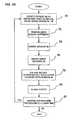
- FIG. 22A method for fusing spinal bones together will now be described relative to Fig. 22 . It should be understood that this procedure may be used during a vertebrectomy or discectomy or other neurological procedure during which it is desired to fuse spinal bones together.
- the examplewill be described as used during a discectomy procedure during which the discs 18-22 ( Fig. 1 ) are removed so that spinal bones 10-16 may be fused together.
- the procedurebegins by situating a patient P on an operating table (not shown) and providing an appropriate incision as conventionally known to expose the spinal bones such as the bones 10-16 illustrated in the side view shown in Fig. 1 and in the anterior view illustrated in Fig. 15 . (Block 70 in Fig. 22 ).
- the vertebrae or discssuch as discs 18-22 in Figs. 1 and 15 , are surgically removed revealing the areas 26-30 in Figs. 2 and 16 .
- the housings 32are inserted in the direction of arrow A ( Fig. 3 ) into the areas 26, 28 and 30 until the migration preventers 40b, 48c, 50c and 50d engage the surfaces of the spinal bones 10-16, such as the surfaces 10a and 12a illustrated in Fig. 3 . (Block 74 in Fig. 22 ).
- the migration preventersfacilitate preventing inserting the housing 32 to a point which would cause the wall 32c to engage the spinal column S.
- the housing 32cooperates with adjacent spinal bones, such as bones 10 and 12 to define the graft receiving area or cavity 34 in which the graft material 38 ( Fig. 4 ) may be inserted.
- these graft areas 34-36may comprise a shape which is generally rectangular, as defined by the shape of the housing 32, but it could comprise another shape by simply providing a housing 32 having a different predetermined shape.
- the housing 32may be provided in a circular or arcuate shape in which case the graft area 34 would define a generally circular or arcuate area which would cause the graft material to form a similar shape.
- Other curved or multi-sided shapesmay be defined by providing an appropriately or correspondingly shaped housing 32, depending on the selected or desired shape that the physician would like the fused graft material 38 to assume after it has fused to the adjacent spinal bones.
- the cover 42is situated in the slot or area 52 defined by the walls 48 and 50.
- the cover 42facilitates covering the openings, such as openings 34a and 36a of the graft areas 34 and 36, respectively. The surgeon secures the cover 42 to one or more of the bones, as illustrated in Figs. 5-6 and 19-20 and then closes the patient (Block 80).
- a feature of the inventionis that it provides a fixing system for fixing the location of the bones 12-16 relative to each other. Simultaneously, the system 24 permits the housing 32 to "float" between adjacent bones, such as bones 10 and 12 in Figs. 3 and 6 . This is advantageous for reasons mentioned earlier herein.
- Another advantage on this feature of the inventionis that if it is necessary to operate on the same patient at a later time (Block 82 in Fig. 24 ) and, for example, add one or more housings 32 in order to fuse other spinal bones together, then the cover 42 can simply be removed at a later time, another discectomy or vertebrectomy performed and another housing 32 inserted.
- Another cover 42or perhaps a second cover may then be used to seal the additional housing 32 after it is situated in the manner described herein.
- this inventionprovides a system and method which is flexible and will permit the addition or insertion of additional housings 32 of the same or different sizes during a second operating procedure as illustrated in Block 82.
- Figs. 1-8 and 15-20illustrate the general procedure and use of the invention in an illustrative discectomy wherein three discs are removed, replaced with housing 32, and graft material 38 inserted as described and cover 42 situated and mounted as described herein.
- three discs 18-22are removed and the spinal bones 12-16 are fused together using the system and method as shown and described. It should be appreciated, however, that this system and method may be used with fewer or more housings 32 and with one or a plurality of covers 42 as may be desired or required. For example, if only one of the discs 18-22 needed to be excised and only two of the spinal bones 10-16 fused together, then only one housing 32 and cover 42 may be necessary.
- the housings 32may comprise a different dimension or different height H ( Fig. 14 ) to span a greater area, such as the area H4 illustrated in Figs. 13 and 14 .
- Figs. 13 and 14illustrates a vertebrectomy wherein the spinal bone 12 has been removed along with the disc between spinal bones 14 and 16.
- Thisprovides areas 80 and 81 in which an elongated housing 32', such as the housing 32' illustrated in Fig. 14 may be inserted.
- graft areas 82 and 84are provided for receiving the graft material 38.
- the cover 42would have a corresponding elongated shape for fixing the bones 10 and 14 together and for covering both openings 82 and 84 or housings 32 and 32'.
- the inventionmay be used in a multitude of procedures, such as a vertebrectomy ( Figs. 8 and 9 ), discectomy ( Figs. 1-7 , 13-20 , or even a combination of a vertebrectomy and discectomy as illustrated in Figs. 13-14 .
- a combination of different sizes of housings 32 and covers 42may be used as shown. Although it is preferred that a single cover 42 be used, it may be desired in some applications to use multiple covers 42, such as where the removed discs are not adjacent.
- the housings 32comprise the crossbar 60 which cooperate with the cover 42 to prevent anterior migration of the housing after the screws 46 are secured to the spinal bones as illustrated in Figs. 6 , 9 and 13 .
- Figs. 25-30illustrate other variants of housings.
- a generally U-shaped housing 32is provided without the walls 48 and 50 or crossbar 60. This embodiment may be useful. This may be useful if it were desired to insert housing 32 in local anatomy so that it could be loaded from the side or laterally, rather than anteriorly, as previously described.
- a housing 32"'is provided with the crossbars 60, but without the walls 48 and 50. In this embodiment it may be useful to use such a housing design when the local anatomy provides limited space.
- Fig. 27illustrates yet another housing 32 that is provided with a plurality of protrusion 86, 88, 90 and 92 that do not span completely between the walls 32b or 32a together but yet provide the protrusions 86-92 which will engage the cover 42 if the housing attempts to migrate anteriorly as described earlier herein.
- Figs. 1-24 , 29 and 30show housings where the crossbars 60 are not integrally formed with the housing 32, but received in the notched areas 90 as shown. As mentioned earlier, the crossbars 60 may be separate or may be integrally provided with the housing 32. Providing detachable crossbars 60, such as is shown in the embodiments illustrated in Figs. 25, 28 and 29 , enable the walls 32a and 32b to flex towards and away from each other.
- the housing 32may be provided with a malleable material in which case the surgeon can change the general U-shape of the housing 32 to accommodate the size or shape of the areas 34 and 36 ( Fig. 17 ).
- housing 32 and cover 42may be made of titanium, polymer or a bioresorbable material.
- Fig. 31illustrates the walls 48 and 50 having notched areas 49 and 51 for receiving the cover 42, thereby eliminating the need for cross bars 60.
- the various examples illustrated in Figs. 1provide a system for inserting graft material 32 into a graft area 34 and 36 ( Fig. 17 ) to fuse a plurality of bones such as bones 10-18 together.
- the system and methodalso provide means for fixing the bones 10-18 relative to each other, while permitting the housing 32 to cooperate with adjacent bones 10-18 to define a graft area 34 and 36 ( Fig. 17 ) and to also float relative to the cover 42.
- the locking system illustrated in Figs. 21-23further facilitates providing a locking system that does not require the use of any tools, yet prevents back out of the screws 46.
Landscapes
- Health & Medical Sciences (AREA)
- Orthopedic Medicine & Surgery (AREA)
- Engineering & Computer Science (AREA)
- Biomedical Technology (AREA)
- Neurology (AREA)
- Life Sciences & Earth Sciences (AREA)
- General Health & Medical Sciences (AREA)
- Surgery (AREA)
- Veterinary Medicine (AREA)
- Heart & Thoracic Surgery (AREA)
- Public Health (AREA)
- Animal Behavior & Ethology (AREA)
- Oral & Maxillofacial Surgery (AREA)
- Vascular Medicine (AREA)
- Transplantation (AREA)
- Nuclear Medicine, Radiotherapy & Molecular Imaging (AREA)
- Cardiology (AREA)
- Medical Informatics (AREA)
- Molecular Biology (AREA)
- Prostheses (AREA)
- Surgical Instruments (AREA)
- Branch Pipes, Bends, And The Like (AREA)
- Separation By Low-Temperature Treatments (AREA)
- Orthopedics, Nursing, And Contraception (AREA)
- Massaging Devices (AREA)
Abstract
Description
- This invention relates to a veritable prosthetic system and device and a method for implanting the device and, more particularly, to a spinal fusion system,
- Many types of prosthetic devices have been proposed in the past. For example,
U.S. Patent 5,192,327 to Brantagan concerns a surgical prosthetic modular implant used singularly or stacked together to support and fuse together adjacent vertebrae or to totally or partially replace one or more vertebrae in a vertebral column. Other surgical implant devices and methods are shown inU.S. Patents 5,192,327 ;5,261,911 ;5,713,899 ;5,776,196 ;6,136,002 ;6,159,245 ;6,224,602 ;6,258,089 ;6,261,586 ;6,264,655 ;6,306,136 ;6,328,738 ,6,592,586 .FR 2827150 DE 4409833 . Some or all of these devices have improved the success rate and have simplified the surgical techniques in inter-body veritable fusion. - Among some of the problems associated with the prior art devices is that after the device is inserted into a patient during a surgical procedure, there was a possibility of retropulsion of the inter-body device and graft material into the spinal cord or other neurological element.
- Another problem with the prior art devices is that grafting material, which was inserted into the devices during the surgical procedure, could not easily be inserted from an anterior direction.
- Moreover, in some of the prior art devices, the cover, if any, was typically fastened directly to the device and to spinal bones, which prevented the cover from being capable of moving relative to the device. In addition, in devices that used a cover, the cover did not function to both retain the grafting material in the device and simultaneously fix the spinal bones relative to each other.
- What is needed, therefore, is a system , which facilitates overcoming one or more of the aforementioned problems as well as other problems and to provide a device that has unique features that will facilitate reducing the risk associated with neurological surgeries and advance the present state of the art.
- The invention comprises a prosthetic implant system according to claim 1.
- This object and advantages of the invention will be apparent from the following description, the accompanying drawing and the appended claims.
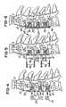
Fig. 1 is a partial side view a human spine illustrating anteriorly discs between various spinal bones;Fig. 2 is a partial side view of the spinal column shown inFig. 1 illustrating several of the discs removed, for example, after surgical procedure;Fig. 3 is a partial side view of the human spine with the housings according to one embodiment of the invention situated therein;Fig. 4 is a partial side view of the human spinal column illustrating graft material being inserted anteriorly into the housing;Fig. 5 is a partial exploded side view of the embodiment shown inFig. 1-4 illustrating a cover and a plurality of screws which will secure the cover to the spinal column;Fig 6 is a side view similar toFig. 5 illustrating after the cover has been mounted to the spinal column;Fig. 7 is a exploded view of the device shown inFig. 6 , illustrating a plurality of housings and a single cover for use with covering the plurality of housings;Fig. 8 is partial side view illustrating an elongated housing and cover used during a vertebrectomy procedure;Fig. 9 is a partial side view of the spinal column illustrated inFig. 8 showing the elongated housing situated between adjacent spinal bones in a single cover to be affixed to those spinal bones;Fig. 10 is an exploded view of the circle area shown inFig. 8 ;Fig. 11 is a exploded view of the elongated housing illustrated inFigs. 8 and 9 and the cover and screws associated therewith;Fig. 12 is a partial fragmentary view of the cover and housing after the cover has been situated between a pair of rails associated with the housing;Fig. 13 illustrates a partial side view of an embodiment showing a plurality of housings of different sizes used with a single cover;Fig. 14 is a exploded view of the housings and cover illustrated inFig. 13 ;Fig. 15 is a partial anterior side view a human spine illustrating the discs between various spinal bones;Fig. 16 is a partial anterior view of the spinal column shown inFig. 1 illustrating several of the discs removed, such as by surgical procedure;Fig. 17 is a partial anterior view of the human spine with the housings according to one embodiment of the invention situated therein;Fig. 18 is a partial anterior view of the human spinal column illustrating graft material being inserted anteriorly into the housing;Fig. 19 is a partial exploded anterior view of the embodiment shown inFig. 1-4 illustrating a cover and a plurality of screws for securing the cover to the spinal column;Fig. 20 is a anterior view similar toFig. 5 illustrating the cover mounted to the spinal column;Fig. 21 is a fragmentary view illustrating various features of the cover;Fig. 22 is another fragmentary view of the cover after the screws are mounted and the locking mechanism retains the screws therein;Fig. 23 is a fragmentary sectional view of the embodiment shown inFig. 22 illustrating various features of the locking mechanism;Fig. 24 is a schematic view of a process or method for fusing spinal bones together;Fig. 25 illustrations another example without crossbars or migration preventers;Fig. 26 is a view of another example showing the crossbars integrally formed in the housing and without migration preventers;Fig. 27 is a view illustrating a plurality of migration preventers, without any crossbars;Fig. 28 is a view illustrating a housing with a plurality of projections which cooperate with the cover to prevent the housing from migrating anteriorly;Fig. 29 is another view of the housing illustrating a plurality of removable crossbars without any migration preventers; andFig. 30 illustrates another example, similar to the devices illustrated earlier relative toFig. 1-20 showing details of the cross bars and notches for receiving them.- Referring now to
Fig. 1 , a partial side view of a patient or person P is shown having a spinal column S and a plurality of spinal bones, such as vertebrae, 10, 12, 14 and 16. Note that a disc, such asdiscs Fig. 1 , is located between adjacent pairs of spinal bones (e.g., betweenbones discs Fig. 2 illustrates a fragmentary view of the spinal column S shown inFig. 1 , with thediscs Fig. 13 . In this type of neurological procedure, it may also be desired to fuse adjacent spinal bones together for reasons that are conventionally known. This invention provides means for facilitating and performing such procedures. For ease of illustration,Figs. 15 - 20 provide corresponding anterior views to the side views shown inFigs. 1-6 , respectively.- In the embodiment being described, a
spinal fusion system 24 is provided for use as a prosthetic implant during a neurological procedure such as the aforementioned vertebrectomy or discectomy. In general, after thediscs Fig. 1 ) are removed, as illustrated inFig. 2 , a plurality of receivingareas Figs. 2 and17 ) are defined by the areas between the surfaces of adjacentspinal bones Fig. 2 , thearea 26 is bounded in part by the surface 10a ofspinal bone 10 and surface 12a ofspinal bone 12. Likewise,area 28 is partially bounded bysurface 12b ofspinal bone 12 and surface 14a ofspinal bone 14, andarea 30 is bounded bysurface 14b ofspinal bone 14 and surface 16a ofspinal bone 16. - As illustrated in
Figs. 3-7 and11 and as will be described in more detail later herein, thespinal fusion system 24 comprises ahousing 32 dimensioned to be situated or received between adjacent spinal bones, such asbones housing 32 is situated in each of the plurality of receivingareas Figs. 3-4 . Eachhousing 32 cooperates with adjacent spinal bones to define a graft area, such asareas Fig. 17 , for receiving graft material 38 (Figs. 4 and18 ). As illustrated inFigs. 4 and18 , thegraft material 38 is situated in theareas housing 32. - As illustrated in
Fig. 11 , thehousing 32 is generally U-shaped as shown. In the embodiment being described, thehousing 32 comprises a well 33 defining multiple sides and comprises a predetermined shape selected to cause the graft material to be formed into a multi-sided fused coupling between adjacent spinal bones, such asbones Fig. 3 . Although not shown, thehousing 32 could define a shape other than rectangular, such as semi-circular, oval or other suitable shape as may be desired. Note that thehousing 32 comprises afirst wall 32a, asecond wall 32b and athird wall 32c joining thefirst wall 32a and thesecond wall 32b. One or more of thewalls 32a-32c may comprise a plurality of holes orapertures 40 which facilitate the fusing process. Theapertures 40 also permit visualization ofgraft material 30 on x-rays. - As mentioned later herein, the predetermined shape defined by the
spinal fusion system 24 may provide a fused multi-sided plug offusion material 32 having a height H (Figs. 14 and16 ) of at least two millimeters, but typically less than approximately 180 millimeters. This height H may vary depending on the vertical size or height H (as viewed inFig. 16 ) of the areas 26-30 to be filled. For example, in thearea 26 illustrated inFigs. 2 ,14 and16 , the height H of thearea 26 generally corresponds to a height H1 (Fig. 1 ) of a disc, such asdisc 18. Thus, the fusion material 38 (Fig. 18 ) would resultantly have a fused height H2 (Fig. 18 ) that generally corresponds to the height H (Fig. 16 ) and height H1 (Fig. 1 ). If, for example, ahousing 32 having a longer height is required, such as height H3 inFig. 14 and height H4 inFig. 13 , such as in the event of a vertebrectomy, then thefusion system 24 andhousing 32 will define a height that generally corresponds to the dimension or height H (Fig. 9 ) to be traversed. Thus, it should be understood that the dimensions of the generallyU-shaped housing 32 of thespinal fusion system 24 is selected depending on the size of the area 26-30 to be filled and the environment or application in which thespinal fusion system 24 is used. In general, the width and depth of thehousing 32 will be approximately 9 - 20 millimeters and 7 - 20 millimeters, respectively. - As illustrated in
Figs. 5-7 ,11 ,14 and21-22 , thespinal fusion system 24 further comprises acover 42 comprising a plurality ofapertures 44 that receive a plurality ofscrews 46, respectively, which are screwed directly into thespinal bones Figs. 5-6 . - As illustrated in
Fig. 11 , thehousing 32 comprises a first rail, channel wall orwall portion 48 and a second rail, channel wall orwall portion 50 which cooperate to define achannel area 52 for receiving thecover 42. It should be understood that when thecover 42 is received in thechannel 52, thesides cover 42 is not directed permanently secured to thehousing 32 after it is received inchannel area 52. This feature permits thehousing 32 secured to thehousing 32 to migrate or float relative to thecover 42 even after thecover 42 is fixed to one or more of the spinal bones 10-16 as illustrated inFigs. 6 and20 . As illustrated inFig. 23 , theedges cover 42 and sides 48a and 50a may be beveled and complementary to facilitate locating and mating engagement between thecover 42 andhousing 32. - As illustrated in
Figs. 3-6 and16-20 , after thegraft material 38 is placed in thehousing 32 and the graft areas 35-36 (Fig. 17 ) defined by thehousing 32 and adjacent spinal bones, then thecover 42 is situated between the walls or rails 48 and 50, as illustrated inFigs. 6 and19 . Thescrews 46 may then be used to secure thecover 42 to one or more of the spinal bones 10-16 as illustrated inFigs. 6 and20 . It should be understood that a feature of the invention is that thecover 42 facilitates aligning thehousings 32 in a substantially co-lineal or relatively aligned position relative to each other and to the spinal bones 10-16, as illustrated inFigs. 6 ,19 and 20 . In the setting of multiple level discectomy, the floatingcover 42 allows limited, controlled settling of the cages orhousings 32 in the vertical plane with respect to thecover 42. As illustrated inFigs. 6 ,8 ,10 and20 , thecover 42 also provides means for providing a mechanical fixation of the adjacent spinal bones 10-16 relative to each other. Thus, while thehousing 32 cooperates with adjacent spinal bones, such asspinal bones graft receiving area 34, the cover is multi-functional in that it not only covers the opening of any graft areas, such as area 34 (Fig. 17 ), but it also secures and retains the spinal bones 10-16 in a fixed spatial relationship relative to each other and relative to thehousings 32. It should also be understood that thecover 42 may be fixed to one or more of the spinal bones 10-16 as may be desired to accomplish either of the aforementioned functions. - As illustrated in
Fig. 11 , note that thewalls projections Figs. 3-6 and17-20 , theprojections housing 32 from migrating posteriorly in the direction of arrow A (Fig. 3 ) toward the spinal cord S or other neurological elements after thehousing 32 is situated between the adjacent spinal bones 10-16 as illustrated. Further, themigration preventers housing 32 between adjacent spinal bones, such as spinal bones 10-16 inFig. 1 , and move thehousing 32 in the direction of arrow A inFig. 3 until themigration preventers spinal bone 10 andmigration preventers spinal bone 12. As illustrated inFig. 3 , after thehousings 32 are situated between the spinal bones 10-16 as shown, themigration preventers wall 32c from being over-inserted by the surgeon or from being over-inserted to a point where it engages the spinal cord S or other neurological elements. - The
spinal fusion system 24 further comprises at least one migration stop orcrossbar 60 as illustrated inFigs. 11, 12 ,29 and 30 . Thecrossbar 60 may be either integrally formed inhousing 32, as shown inFig. 26 , or separate as illustrated inFigs. 11 ,29 and 30 , as illustrated inFigs. 7 ,12 and14 , for example. As illustrated in the exploded view inFigs. 10 and 11 , the surface 60a ofcrossbar 60 engages and cooperates withsurface 42c ofcover 42 to prevent anterior migration in the direction of arrow B). Thus, thespinal fusion system 24 of the embodiment being described provides means for preventing insertion of thehousing 32 to a point where it might engage the spinal cord S (Fig. 3 ) or other neurological elements, such as dura mater, thecal sac, and also means for facilitating prevention of migration of thehousing 32 in an anterior direction or in the direction of arrow B inFig. 10 after thehousing 32 is situated as described herein and thecover 42 is mounted to one or more of the spinal bones 10-16. - It should be understood that a plurality of the migration stops or cross
bars 60 may be used alone or in combination with themigration preventers stops 60 could be detachable, as shown inFig. 26 , or they could be integrally formed in housing 32 (as shown inFig. 26 ). Also, these cross bars 60 may be removably received in the notched receiving areas 94 (Figs. 29 - 30 ). For example, in anatomy that provided limited space, the surgeon may elect not to use a housing withcross bars 60 or use a housing that does not have integrally formed cross bars. - The
system 24 further comprises a system or means for preventing retraction or back out of thescrews 46 after they are screwed into the spinal bones 10-16 in order to secure thecover 42 thereto. Thespinal fusion system 24 may be used with conventional screw lock devices or with the unique locking mechanism and system according to the present invention, which will now be described relative toFigs. 21-23 . - As illustrated in
Figs. 21-23 , thespinal fusion system 24 and, more particularly, cover 42 may be provided with at least one or a plurality ofresilient detents 62 which are generally L-shaped as shown and are resilient so that they can move laterally in the direction of double arrow C inFigs. 21-22 towards and away from a home position (Fig. 21 ) to permit thescrews 46 first received in theapertures 44, and, second, locked into thecover 42. Thereafter, thescrews 46 may be screwed into a spinal bone, such asspinal bone 10, and when a screw head 46a of thescrew 46 engages a detent portion 62a of theresilient lock 62, theresilient lock 62 moves in a direction away from theapertures 44 until the screw head 46a clears the portion 62a. After atop surface 46b of the screw head 46a has cleared the bottom surface 62a1 (as viewed inFig. 23 ) of portion 62a, theresilient lock 62 moves back towardaperture 44 to the home position until the portion 62a and surface 62a1 are operatively positioned oversurface 46b ofscrew 46, thereby retaining and preventing thescrews 46 from backing out of thecover 42 and thereby preventing thescrews 46 from backing out of thespinal bone 10. - In the embodiment being described, the components of the
spinal fusion system 24, such as thehousing 32, firstchannel wall portion 48 and secondchannel wall portion 50,crossbar 60,cover 42 and screws 46 may be made of any desired composition or material such as a polymer, composite polymer, titanium, stainless steel, carbon fiber or other suitable material. - A method for fusing spinal bones together will now be described relative to
Fig. 22 . It should be understood that this procedure may be used during a vertebrectomy or discectomy or other neurological procedure during which it is desired to fuse spinal bones together. For ease of illustration, the example will be described as used during a discectomy procedure during which the discs 18-22 (Fig. 1 ) are removed so that spinal bones 10-16 may be fused together. The procedure begins by situating a patient P on an operating table (not shown) and providing an appropriate incision as conventionally known to expose the spinal bones such as the bones 10-16 illustrated in the side view shown inFig. 1 and in the anterior view illustrated inFig. 15 . (Block 70 inFig. 22 ). AtBlock 72, the vertebrae or discs, such as discs 18-22 inFigs. 1 and15 , are surgically removed revealing the areas 26-30 inFigs. 2 and16 . AtBlock 74, thehousings 32 are inserted in the direction of arrow A (Fig. 3 ) into theareas migration preventers 40b, 48c, 50c and 50d engage the surfaces of the spinal bones 10-16, such as the surfaces 10a and 12a illustrated inFig. 3 . (Block 74 inFig. 22 ). As mentioned earlier herein, the migration preventers facilitate preventing inserting thehousing 32 to a point which would cause thewall 32c to engage the spinal column S. - As illustrated in
Figs. 3 and17 , thehousing 32 cooperates with adjacent spinal bones, such asbones cavity 34 in which the graft material 38 (Fig. 4 ) may be inserted. As mentioned earlier herein, these graft areas 34-36 may comprise a shape which is generally rectangular, as defined by the shape of thehousing 32, but it could comprise another shape by simply providing ahousing 32 having a different predetermined shape. Thus, thehousing 32 may be provided in a circular or arcuate shape in which case thegraft area 34 would define a generally circular or arcuate area which would cause the graft material to form a similar shape. Other curved or multi-sided shapes may be defined by providing an appropriately or correspondingly shapedhousing 32, depending on the selected or desired shape that the physician would like the fusedgraft material 38 to assume after it has fused to the adjacent spinal bones. - At
Block 76, thegraft material 48 is inserted and atBlock 78, thecover 42 is situated in the slot orarea 52 defined by thewalls cover 42 facilitates covering the openings, such asopenings 34a and 36a of thegraft areas cover 42 to one or more of the bones, as illustrated inFigs. 5-6 and19-20 and then closes the patient (Block 80). - Again, and as mentioned earlier, a feature of the invention is that it provides a fixing system for fixing the location of the bones 12-16 relative to each other. Simultaneously, the
system 24 permits thehousing 32 to "float" between adjacent bones, such asbones Figs. 3 and6 . This is advantageous for reasons mentioned earlier herein. Another advantage on this feature of the invention is that if it is necessary to operate on the same patient at a later time (Block 82 inFig. 24 ) and, for example, add one ormore housings 32 in order to fuse other spinal bones together, then thecover 42 can simply be removed at a later time, another discectomy or vertebrectomy performed and anotherhousing 32 inserted. Anothercover 42, or perhaps a second cover may then be used to seal theadditional housing 32 after it is situated in the manner described herein. Thus, this invention provides a system and method which is flexible and will permit the addition or insertion ofadditional housings 32 of the same or different sizes during a second operating procedure as illustrated inBlock 82. Figs. 1-8 and15-20 illustrate the general procedure and use of the invention in an illustrative discectomy wherein three discs are removed, replaced withhousing 32, andgraft material 38 inserted as described and cover 42 situated and mounted as described herein. In the illustration shown inFigs. 1-8 and15-20 , three discs 18-22 are removed and the spinal bones 12-16 are fused together using the system and method as shown and described. It should be appreciated, however, that this system and method may be used with fewer ormore housings 32 and with one or a plurality ofcovers 42 as may be desired or required. For example, if only one of the discs 18-22 needed to be excised and only two of the spinal bones 10-16 fused together, then only onehousing 32 and cover 42 may be necessary. Likewise, as mentioned earlier herein, thehousings 32 may comprise a different dimension or different height H (Fig. 14 ) to span a greater area, such as the area H4 illustrated inFigs. 13 and 14 . For example,Figs. 13 and 14 illustrates a vertebrectomy wherein thespinal bone 12 has been removed along with the disc betweenspinal bones areas 80 and 81 in which an elongated housing 32', such as the housing 32' illustrated inFig. 14 may be inserted. After thehousings 32 and 32' are inserted between the spinal bones 10-14 and 14-16 as shown inFig. 13 ,graft areas graft material 38. As illustrated inFig. 13 , thecover 42 would have a corresponding elongated shape for fixing thebones openings housings 32 and 32'.- It is also anticipated that the invention may be used in a multitude of procedures, such as a vertebrectomy (
Figs. 8 and 9 ), discectomy (Figs. 1-7 ,13-20 , or even a combination of a vertebrectomy and discectomy as illustrated inFigs. 13-14 . As mentioned and described earlier herein, a combination of different sizes ofhousings 32 and covers 42 may be used as shown. Although it is preferred that asingle cover 42 be used, it may be desired in some applications to usemultiple covers 42, such as where the removed discs are not adjacent. - In the illustrations being described, the
housings 32 comprise thecrossbar 60 which cooperate with thecover 42 to prevent anterior migration of the housing after thescrews 46 are secured to the spinal bones as illustrated inFigs. 6 ,9 and13 . Figs. 25-30 illustrate other variants of housings. InFig. 25 , a generallyU-shaped housing 32 is provided without thewalls crossbar 60. This embodiment may be useful. This may be useful if it were desired to inserthousing 32 in local anatomy so that it could be loaded from the side or laterally, rather than anteriorly, as previously described. InFig. 26 ahousing 32"' is provided with thecrossbars 60, but without thewalls Fig. 27 illustrates yet anotherhousing 32 that is provided with a plurality ofprotrusion walls cover 42 if the housing attempts to migrate anteriorly as described earlier herein.Figs. 1-24 ,29 and 30 show housings where thecrossbars 60 are not integrally formed with thehousing 32, but received in the notchedareas 90 as shown. As mentioned earlier, thecrossbars 60 may be separate or may be integrally provided with thehousing 32. Providingdetachable crossbars 60, such as is shown in the embodiments illustrated inFigs. 25, 28 and 29 , enable thewalls housing 32 may be provided with a malleable material in which case the surgeon can change the general U-shape of thehousing 32 to accommodate the size or shape of theareas 34 and 36 (Fig. 17 ). In the embodiment described,housing 32 and cover 42 may be made of titanium, polymer or a bioresorbable material.- Fig. 31 illustrates the
walls cover 42, thereby eliminating the need for cross bars 60. Advantageously, the various examples illustrated inFigs. 1 , provide a system for insertinggraft material 32 into agraft area 34 and 36 (Fig. 17 ) to fuse a plurality of bones such as bones 10-18 together. The system and method also provide means for fixing the bones 10-18 relative to each other, while permitting thehousing 32 to cooperate with adjacent bones 10-18 to define agraft area 34 and 36 (Fig. 17 ) and to also float relative to thecover 42. The locking system illustrated inFigs. 21-23 further facilitates providing a locking system that does not require the use of any tools, yet prevents back out of thescrews 46. - While the apparatus described constitutes preferred embodiments of this invention, it is to be understood that the invention is not limited to this precise apparatus , and that changes may be made in either without departing from the scope of the invention, which is defined in the appended claims.
Claims (4)
- A prosthetic implant system comprising: CLAIMS- at least one screw (46),- a prosthestic implant plate (42), comprising a generally planar member; anda lock (62) integral with the generally planar member for preventing withdrawal of said at least one screw (46) after said at least one screw (46) is screwed into a spinal bone (10-16),
wherein each lock (62) comprises a resilient member (62) associated with an opening for permitting said screw (46) to be situated in said opening (44) and screwed into a spinal bone (10-16), said at least one resilient member (62) preventing said screw (46) from withdrawing from said spinal bone (10-16),
characterized in the the integral lock (62) comprises an elongated resilient arm for locking said screw (46) into said opening (44) when screwed into the spinal bore (10-16) comprising a detent portion (62a), the elongated resilient arm. (62) being movable between:- a home position wherein the detent portion (62a) is able to retain the screw (46) in the member (42); and- a flexed position wherein the detent portion (62a) is moved away from its home position,andin that the screw comprises:- a screw head (46a) engaging the detent portion (62a) to elastically flex to the flexed position in response to the screw being screwed and moving the integral lock (62) away from said opening (44); and- a surface (46b) over which the detent portion (62a) is positionned in the home position to prevent the screw from backing out from the member (42). - The prosthetic implant system as recited in claim 1, wherein said resilient member is generally L-shaped in cross-section.
- The prosthetic implant system as recited in any previous claims, wherein said generally planar member is selected within titanium, stainless steel, and a composite polymer.
- The prosthetic implant system as recited in any previous claims, comprising openings (44) therein for respective screws (46).
Applications Claiming Priority (2)
| Application Number | Priority Date | Filing Date | Title |
|---|---|---|---|
| US10/675,361US7182782B2 (en) | 2003-09-30 | 2003-09-30 | Spinal fusion system and method for fusing spinal bones |
| EP04785234AEP1684673B1 (en) | 2003-09-30 | 2004-09-29 | A spinal fusion system for fusing spinal bones |
Related Parent Applications (2)
| Application Number | Title | Priority Date | Filing Date |
|---|---|---|---|
| EP04785234ADivisionEP1684673B1 (en) | 2003-09-30 | 2004-09-29 | A spinal fusion system for fusing spinal bones |
| EP04785234.8Division | 2004-09-29 |
Publications (4)
| Publication Number | Publication Date |
|---|---|
| EP2263616A1 EP2263616A1 (en) | 2010-12-22 |
| EP2263616B1true EP2263616B1 (en) | 2012-08-22 |
| EP2263616B8 EP2263616B8 (en) | 2012-10-03 |
| EP2263616B9 EP2263616B9 (en) | 2012-11-07 |
Family
ID=34377128
Family Applications (3)
| Application Number | Title | Priority Date | Filing Date |
|---|---|---|---|
| EP10168172AExpired - LifetimeEP2263616B9 (en) | 2003-09-30 | 2004-09-29 | A prosthetic implant plate |
| EP10168168AExpired - LifetimeEP2263615B8 (en) | 2003-09-30 | 2004-09-29 | A spinal fusion system |
| EP04785234AExpired - LifetimeEP1684673B1 (en) | 2003-09-30 | 2004-09-29 | A spinal fusion system for fusing spinal bones |
Family Applications After (2)
| Application Number | Title | Priority Date | Filing Date |
|---|---|---|---|
| EP10168168AExpired - LifetimeEP2263615B8 (en) | 2003-09-30 | 2004-09-29 | A spinal fusion system |
| EP04785234AExpired - LifetimeEP1684673B1 (en) | 2003-09-30 | 2004-09-29 | A spinal fusion system for fusing spinal bones |
Country Status (5)
| Country | Link |
|---|---|
| US (2) | US7182782B2 (en) |
| EP (3) | EP2263616B9 (en) |
| AT (1) | ATE475378T1 (en) |
| DE (1) | DE602004028391D1 (en) |
| WO (1) | WO2005032412A2 (en) |
Families Citing this family (118)
| Publication number | Priority date | Publication date | Assignee | Title |
|---|---|---|---|---|
| US6206922B1 (en)* | 1995-03-27 | 2001-03-27 | Sdgi Holdings, Inc. | Methods and instruments for interbody fusion |
| US7972337B2 (en) | 2005-12-28 | 2011-07-05 | Intrinsic Therapeutics, Inc. | Devices and methods for bone anchoring |
| US7094258B2 (en)* | 1999-08-18 | 2006-08-22 | Intrinsic Therapeutics, Inc. | Methods of reinforcing an annulus fibrosis |
| CA2425951C (en)* | 1999-08-18 | 2008-09-16 | Intrinsic Therapeutics, Inc. | Devices and method for nucleus pulposus augmentation and retention |
| US7998213B2 (en)* | 1999-08-18 | 2011-08-16 | Intrinsic Therapeutics, Inc. | Intervertebral disc herniation repair |
| US7553329B2 (en)* | 1999-08-18 | 2009-06-30 | Intrinsic Therapeutics, Inc. | Stabilized intervertebral disc barrier |
| EP1624832A4 (en)* | 1999-08-18 | 2008-12-24 | Intrinsic Therapeutics Inc | Devices and method for augmenting a vertebral disc nucleus |
| US8323341B2 (en) | 2007-09-07 | 2012-12-04 | Intrinsic Therapeutics, Inc. | Impaction grafting for vertebral fusion |
| US7717961B2 (en) | 1999-08-18 | 2010-05-18 | Intrinsic Therapeutics, Inc. | Apparatus delivery in an intervertebral disc |
| EP1470803A1 (en)* | 2003-04-23 | 2004-10-27 | Sepitec Foundation | Spondylodesis device |
| JP2007515988A (en)* | 2003-06-20 | 2007-06-21 | イントリンジック セラピューティックス インコーポレイテッド | Device and method for delivering an implant from an annular defect of an intervertebral disc |
| US8821553B2 (en) | 2003-09-30 | 2014-09-02 | X-Spine Systems, Inc. | Spinal fusion system utilizing an implant plate having at least one integral lock |
| US9078706B2 (en)* | 2003-09-30 | 2015-07-14 | X-Spine Systems, Inc. | Intervertebral fusion device utilizing multiple mobile uniaxial and bidirectional screw interface plates |
| US7641701B2 (en)* | 2003-09-30 | 2010-01-05 | X-Spine Systems, Inc. | Spinal fusion system and method for fusing spinal bones |
| US8372152B2 (en)* | 2003-09-30 | 2013-02-12 | X-Spine Systems, Inc. | Spinal fusion system utilizing an implant plate having at least one integral lock and ratchet lock |
| US8062367B2 (en) | 2003-09-30 | 2011-11-22 | X-Spine Systems, Inc. | Screw locking mechanism and method |
| US7854752B2 (en) | 2004-08-09 | 2010-12-21 | Theken Spine, Llc | System and method for dynamic skeletal stabilization |
| WO2006058221A2 (en) | 2004-11-24 | 2006-06-01 | Abdou Samy M | Devices and methods for inter-vertebral orthopedic device placement |
| US7604654B2 (en) | 2005-02-22 | 2009-10-20 | Stryker Spine | Apparatus and method for dynamic vertebral stabilization |
| US8986383B2 (en) | 2005-03-24 | 2015-03-24 | Igip, Llc | End cap and connector for a spinal implant |
| US9456907B1 (en) | 2005-03-24 | 2016-10-04 | Igip, Llc | Extendable spinal implant |
| US8673006B2 (en)* | 2005-03-24 | 2014-03-18 | Igip, Llc | Spinal implant |
| US8016887B1 (en) | 2005-03-24 | 2011-09-13 | Cardinal Spine, Llc | Spinal implant with overlay |
| US8226718B2 (en)* | 2005-03-24 | 2012-07-24 | Cardinal Spine, Llc | Spinal implant and method of using spinal implant |
| US8246683B2 (en)* | 2005-03-24 | 2012-08-21 | Cardinal Spine, Llc | Spinal implant |
| US8361149B2 (en)* | 2005-03-24 | 2013-01-29 | Cardinal Spine, Llc | Wedge-like spinal implant |
| US7435261B1 (en)* | 2005-03-24 | 2008-10-14 | Frank Castro | Spinal implant and method of using spinal implant |
| US8137385B2 (en) | 2005-10-31 | 2012-03-20 | Stryker Spine | System and method for dynamic vertebral stabilization |
| US7887595B1 (en) | 2005-12-05 | 2011-02-15 | Nuvasive, Inc. | Methods and apparatus for spinal fusion |
| US8025681B2 (en)* | 2006-03-29 | 2011-09-27 | Theken Spine, Llc | Dynamic motion spinal stabilization system |
| US8114162B1 (en) | 2006-08-09 | 2012-02-14 | Nuvasive, Inc. | Spinal fusion implant and related methods |
| US8506636B2 (en) | 2006-09-08 | 2013-08-13 | Theken Spine, Llc | Offset radius lordosis |
| US20080077150A1 (en)* | 2006-09-22 | 2008-03-27 | Linh Nguyen | Steerable rasp/trial member inserter and method of use |
| USD708747S1 (en) | 2006-09-25 | 2014-07-08 | Nuvasive, Inc. | Spinal fusion implant |
| US9039768B2 (en) | 2006-12-22 | 2015-05-26 | Medos International Sarl | Composite vertebral spacers and instrument |
| US20080249569A1 (en)* | 2007-04-03 | 2008-10-09 | Warsaw Orthopedic, Inc. | Implant Face Plates |
| US8425607B2 (en)* | 2007-04-03 | 2013-04-23 | Warsaw Orthopedic, Inc. | Anchor member locking features |
| US8268000B2 (en)* | 2007-04-03 | 2012-09-18 | Warsaw Orthopedic, Inc. | Composite interbody spacer |
| US8043346B2 (en)* | 2007-05-18 | 2011-10-25 | Custom Spine, Inc. | Anterior cervical plate with independent spring-loaded locking slides for each screw |
| US20090177239A1 (en)* | 2007-08-06 | 2009-07-09 | Michael Castro | Cervical plate instrument kit |
| US20110196492A1 (en)* | 2007-09-07 | 2011-08-11 | Intrinsic Therapeutics, Inc. | Bone anchoring systems |
| EP3184065B1 (en) | 2007-11-09 | 2019-06-19 | Stryker European Holdings I, LLC | Cervical plate with a feedback device for selective association with bone screw blocking mechanism |
| US8088163B1 (en) | 2008-02-06 | 2012-01-03 | Kleiner Jeffrey B | Tools and methods for spinal fusion |
| US20090248092A1 (en) | 2008-03-26 | 2009-10-01 | Jonathan Bellas | Posterior Intervertebral Disc Inserter and Expansion Techniques |
| US20210378834A1 (en) | 2008-05-22 | 2021-12-09 | Spinal Surgical Strategies, Inc., A Nevada Corporation D/B/A Kleiner Device Labs | Spinal fusion cage system with inserter |
| US8241329B2 (en)* | 2008-07-05 | 2012-08-14 | Abdou M Samy | Device and method for the prevention of multi-level vertebral extension |
| USD853560S1 (en) | 2008-10-09 | 2019-07-09 | Nuvasive, Inc. | Spinal implant insertion device |
| US8795340B2 (en)* | 2008-11-07 | 2014-08-05 | Globus Medical, Inc. | Vertical inline plate |
| US9717403B2 (en) | 2008-12-05 | 2017-08-01 | Jeffrey B. Kleiner | Method and apparatus for performing retro peritoneal dissection |
| US8864654B2 (en) | 2010-04-20 | 2014-10-21 | Jeffrey B. Kleiner | Method and apparatus for performing retro peritoneal dissection |
| US8366748B2 (en) | 2008-12-05 | 2013-02-05 | Kleiner Jeffrey | Apparatus and method of spinal implant and fusion |
| USD656610S1 (en) | 2009-02-06 | 2012-03-27 | Kleiner Jeffrey B | Spinal distraction instrument |
| US9247943B1 (en) | 2009-02-06 | 2016-02-02 | Kleiner Intellectual Property, Llc | Devices and methods for preparing an intervertebral workspace |
| US9220547B2 (en) | 2009-03-27 | 2015-12-29 | Spinal Elements, Inc. | Flanged interbody fusion device |
| US9526620B2 (en)* | 2009-03-30 | 2016-12-27 | DePuy Synthes Products, Inc. | Zero profile spinal fusion cage |
| USD723682S1 (en) | 2013-05-03 | 2015-03-03 | Spinal Surgical Strategies, Llc | Bone graft delivery tool |
| USD750249S1 (en) | 2014-10-20 | 2016-02-23 | Spinal Surgical Strategies, Llc | Expandable fusion cage |
| US9060877B2 (en) | 2009-09-18 | 2015-06-23 | Spinal Surgical Strategies, Llc | Fusion cage with combined biological delivery system |
| US9186193B2 (en) | 2009-09-18 | 2015-11-17 | Spinal Surgical Strategies, Llc | Fusion cage with combined biological delivery system |
| US8906028B2 (en) | 2009-09-18 | 2014-12-09 | Spinal Surgical Strategies, Llc | Bone graft delivery device and method of using the same |
| US9629729B2 (en) | 2009-09-18 | 2017-04-25 | Spinal Surgical Strategies, Llc | Biological delivery system with adaptable fusion cage interface |
| US20170238984A1 (en) | 2009-09-18 | 2017-08-24 | Spinal Surgical Strategies, Llc | Bone graft delivery device with positioning handle |
| US8685031B2 (en) | 2009-09-18 | 2014-04-01 | Spinal Surgical Strategies, Llc | Bone graft delivery system |
| US9173694B2 (en) | 2009-09-18 | 2015-11-03 | Spinal Surgical Strategies, Llc | Fusion cage with combined biological delivery system |
| US10245159B1 (en) | 2009-09-18 | 2019-04-02 | Spinal Surgical Strategies, Llc | Bone graft delivery system and method for using same |
| US10973656B2 (en) | 2009-09-18 | 2021-04-13 | Spinal Surgical Strategies, Inc. | Bone graft delivery system and method for using same |
| US8764806B2 (en) | 2009-12-07 | 2014-07-01 | Samy Abdou | Devices and methods for minimally invasive spinal stabilization and instrumentation |
| US9393129B2 (en) | 2009-12-10 | 2016-07-19 | DePuy Synthes Products, Inc. | Bellows-like expandable interbody fusion cage |
| US8945227B2 (en)* | 2010-02-01 | 2015-02-03 | X-Spine Systems, Inc. | Spinal implant co-insertion system and method |
| EP2547292B1 (en) | 2010-03-16 | 2019-04-24 | Pinnacle Spine Group, LLC | Ntervertebral implants and graft delivery systems |
| US8425569B2 (en)* | 2010-05-19 | 2013-04-23 | Transcorp, Inc. | Implantable vertebral frame systems and related methods for spinal repair |
| US9402734B2 (en) | 2010-07-30 | 2016-08-02 | Igip, Llc | Spacer for spinal implant |
| US8753396B1 (en) | 2010-09-13 | 2014-06-17 | Theken Spine, Llc | Intervertebral implant having back-out prevention feature |
| US11529241B2 (en) | 2010-09-23 | 2022-12-20 | DePuy Synthes Products, Inc. | Fusion cage with in-line single piece fixation |
| US20120078372A1 (en) | 2010-09-23 | 2012-03-29 | Thomas Gamache | Novel implant inserter having a laterally-extending dovetail engagement feature |
| US20120078373A1 (en) | 2010-09-23 | 2012-03-29 | Thomas Gamache | Stand alone intervertebral fusion device |
| US9358122B2 (en) | 2011-01-07 | 2016-06-07 | K2M, Inc. | Interbody spacer |
| US11154338B2 (en) | 2011-01-20 | 2021-10-26 | Alphatec Spine, Inc. | Bone fixation systems and methods |
| US9271770B2 (en) | 2011-01-20 | 2016-03-01 | Alphatec Spine, Inc | Bone fixation systems and methods |
| US8940030B1 (en) | 2011-01-28 | 2015-01-27 | Nuvasive, Inc. | Spinal fixation system and related methods |
| US9700425B1 (en) | 2011-03-20 | 2017-07-11 | Nuvasive, Inc. | Vertebral body replacement and insertion methods |
| US10226284B2 (en)* | 2011-09-01 | 2019-03-12 | Globus Medical, Inc. | Laminoplasty plates, systems, and devices, and methods relating to the same |
| US9248028B2 (en) | 2011-09-16 | 2016-02-02 | DePuy Synthes Products, Inc. | Removable, bone-securing cover plate for intervertebral fusion cage |
| US8845728B1 (en) | 2011-09-23 | 2014-09-30 | Samy Abdou | Spinal fixation devices and methods of use |
| US20140058446A1 (en)* | 2011-09-28 | 2014-02-27 | Avi Bernstein | Spinal implant system |
| US9380932B1 (en) | 2011-11-02 | 2016-07-05 | Pinnacle Spine Group, Llc | Retractor devices for minimally invasive access to the spine |
| US8784459B2 (en) | 2012-01-17 | 2014-07-22 | Genesys Spine | Spinal plate and locking screw devices, methods, and systems |
| US20130226240A1 (en) | 2012-02-22 | 2013-08-29 | Samy Abdou | Spinous process fixation devices and methods of use |
| US9271836B2 (en) | 2012-03-06 | 2016-03-01 | DePuy Synthes Products, Inc. | Nubbed plate |
| US10076364B2 (en)* | 2012-06-29 | 2018-09-18 | K2M, Inc. | Minimal-profile anterior cervical plate and cage apparatus and method of using same |
| US8814912B2 (en) | 2012-07-27 | 2014-08-26 | Zimmer Spine, Inc. | Bone stabilization member with bone screw retention mechanism |
| US9198767B2 (en) | 2012-08-28 | 2015-12-01 | Samy Abdou | Devices and methods for spinal stabilization and instrumentation |
| US8475533B1 (en)* | 2012-09-27 | 2013-07-02 | Igip, Llc | System and stabilizer for spinal implant and methods of assisting stabilization of spinal implant |
| US9320617B2 (en) | 2012-10-22 | 2016-04-26 | Cogent Spine, LLC | Devices and methods for spinal stabilization and instrumentation |
| US10182921B2 (en) | 2012-11-09 | 2019-01-22 | DePuy Synthes Products, Inc. | Interbody device with opening to allow packing graft and other biologics |
| US10327910B2 (en) | 2013-03-14 | 2019-06-25 | X-Spine Systems, Inc. | Spinal implant and assembly |
| WO2014159739A1 (en) | 2013-03-14 | 2014-10-02 | Pinnacle Spine Group, Llc | Interbody implants and graft delivery systems |
| US9055983B1 (en)* | 2014-04-24 | 2015-06-16 | Amendia, Inc. | Self-locking bone screw receiver |
| US9913672B2 (en) | 2014-05-28 | 2018-03-13 | Genesys Spine | Resiliant spinal plate system |
| US9526533B1 (en)* | 2014-09-12 | 2016-12-27 | Roberto J. Aranibar | Spinal repair implants and related methods |
| WO2016137983A1 (en) | 2015-02-24 | 2016-09-01 | X-Spine Systems, Inc. | Modular interspinous fixation system with threaded component |
| US10610375B2 (en)* | 2015-08-19 | 2020-04-07 | Raymond J. Quinlan | Spinal fusion device and method of using same |
| US10857003B1 (en) | 2015-10-14 | 2020-12-08 | Samy Abdou | Devices and methods for vertebral stabilization |
| USD797290S1 (en) | 2015-10-19 | 2017-09-12 | Spinal Surgical Strategies, Llc | Bone graft delivery tool |
| US10376292B2 (en) | 2016-03-03 | 2019-08-13 | Globus Medical, Inc | Lamina plate assembly |
| US11090166B2 (en) | 2016-03-03 | 2021-08-17 | Globus Medical, Inc. | Lamina plate assembly |
| US10667916B2 (en) | 2016-03-03 | 2020-06-02 | Globus Medical, Inc. | Lamina plate assembly |
| US10973648B1 (en) | 2016-10-25 | 2021-04-13 | Samy Abdou | Devices and methods for vertebral bone realignment |
| US10744000B1 (en) | 2016-10-25 | 2020-08-18 | Samy Abdou | Devices and methods for vertebral bone realignment |
| US10940016B2 (en) | 2017-07-05 | 2021-03-09 | Medos International Sarl | Expandable intervertebral fusion cage |
| US11272963B2 (en) | 2017-11-16 | 2022-03-15 | Globus Medical, Inc. | Anterior cervical plate assembly |
| US11234742B2 (en) | 2017-11-16 | 2022-02-01 | Globus Medical, Inc. | Anterior cervical plate assembly |
| US11304734B2 (en) | 2017-11-16 | 2022-04-19 | Globus Medical Inc. | Anterior cervical plate assembly |
| US11229460B2 (en) | 2017-11-16 | 2022-01-25 | Globus Medical, Inc. | Anterior cervical plate assembly |
| AU2019342137A1 (en) | 2018-09-20 | 2021-03-25 | Spinal Elements, Inc. | Spinal implant device |
| US11179248B2 (en) | 2018-10-02 | 2021-11-23 | Samy Abdou | Devices and methods for spinal implantation |
| US11911284B2 (en) | 2020-11-19 | 2024-02-27 | Spinal Elements, Inc. | Curved expandable interbody devices and deployment tools |
| WO2022133456A1 (en) | 2020-12-17 | 2022-06-23 | Spinal Elements, Inc. | Spinal implant device |
Family Cites Families (125)
| Publication number | Priority date | Publication date | Assignee | Title |
|---|---|---|---|---|
| US1025008A (en) | 1911-08-07 | 1912-04-30 | Lucien Luttrell Miner | Brace for fractured bones. |
| US2677369A (en) | 1952-03-26 | 1954-05-04 | Fred L Knowles | Apparatus for treatment of the spinal column |
| SE391122B (en) | 1971-01-25 | 1977-02-07 | Cutter Lab | PROTESTS IN THE FORM OF A SPINE BONIC DISC AND PROCEDURES FOR MANUFACTURE THEREOF |
| US3848601A (en) | 1972-06-14 | 1974-11-19 | G Ma | Method for interbody fusion of the spine |
| DE2713837C2 (en) | 1977-03-25 | 1978-10-26 | Erhard Dr. 1000 Berlin Westerhoff | Drive device for a distraction device |
| CA1146301A (en) | 1980-06-13 | 1983-05-17 | J. David Kuntz | Intervertebral disc prosthesis |
| US4309777A (en) | 1980-11-13 | 1982-01-12 | Patil Arun A | Artificial intervertebral disc |
| FR2519857A1 (en) | 1982-01-19 | 1983-07-22 | Butel Jean | DEVICE FOR OSTEOSYNTHESIS OF THE FRACTURES OF THE END OF THE FEMUR |
| US4553273A (en) | 1983-11-23 | 1985-11-19 | Henry Ford Hospital | Vertebral body prosthesis and spine stabilizing method |
| US4611581A (en) | 1983-12-16 | 1986-09-16 | Acromed Corporation | Apparatus for straightening spinal columns |
| US4696290A (en) | 1983-12-16 | 1987-09-29 | Acromed Corporation | Apparatus for straightening spinal columns |
| EP0176728B1 (en) | 1984-09-04 | 1989-07-26 | Humboldt-Universität zu Berlin | Intervertebral-disc prosthesis |
| FR2570594B1 (en) | 1984-09-26 | 1989-02-24 | Kehr Pierre | VERTEBRAL PROSTHESIS, PARTICULARLY FOR CERVICAL VERTEBRES |
| US4599086A (en) | 1985-06-07 | 1986-07-08 | Doty James R | Spine stabilization device and method |
| US4743256A (en) | 1985-10-04 | 1988-05-10 | Brantigan John W | Surgical prosthetic implant facilitating vertebral interbody fusion and method |
| DE3701533A1 (en) | 1987-01-21 | 1988-08-04 | Medi System Gmbh | OSTEOSYNTHESIS TOOLS |
| US4834757A (en) | 1987-01-22 | 1989-05-30 | Brantigan John W | Prosthetic implant |
| US4714469A (en) | 1987-02-26 | 1987-12-22 | Pfizer Hospital Products Group, Inc. | Spinal implant |
| DE3809793A1 (en) | 1988-03-23 | 1989-10-05 | Link Waldemar Gmbh Co | SURGICAL INSTRUMENT SET |
| US5084049A (en) | 1989-02-08 | 1992-01-28 | Acromed Corporation | Transverse connector for spinal column corrective devices |
| DE3923995A1 (en) | 1989-07-20 | 1991-01-31 | Lutz Biedermann | BONE STABILIZING ELEMENT |
| FR2668361A1 (en) | 1990-10-30 | 1992-04-30 | Mai Christian | OSTEOSYNTHESIS CLIP AND PLATE WITH SELF-RETENTIVE DYNAMIC COMPRESSION. |
| US5085660A (en) | 1990-11-19 | 1992-02-04 | Lin Kwan C | Innovative locking plate system |
| US5192327A (en) | 1991-03-22 | 1993-03-09 | Brantigan John W | Surgical prosthetic implant for vertebrae |
| US5261911A (en) | 1991-06-18 | 1993-11-16 | Allen Carl | Anterolateral spinal fixation system |
| US5290312A (en) | 1991-09-03 | 1994-03-01 | Alphatec | Artificial vertebral body |
| US5534031A (en) | 1992-01-28 | 1996-07-09 | Asahi Kogaku Kogyo Kabushiki Kaisha | Prosthesis for spanning a space formed upon removal of an intervertebral disk |
| US5324290A (en) | 1992-09-24 | 1994-06-28 | Danek Medical, Inc. | Anterior thoracolumbar plate |
| US5702395A (en) | 1992-11-10 | 1997-12-30 | Sofamor S.N.C. | Spine osteosynthesis instrumentation for an anterior approach |
| DE69320593T2 (en) | 1992-11-25 | 1999-03-04 | Codman & Shurtleff, Inc., Randolph, Mass. | Bone plate system |
| US5364399A (en) | 1993-02-05 | 1994-11-15 | Danek Medical, Inc. | Anterior cervical plating system |
| US5405391A (en)* | 1993-02-16 | 1995-04-11 | Hednerson; Fraser C. | Fusion stabilization chamber |
| US6066175A (en)* | 1993-02-16 | 2000-05-23 | Henderson; Fraser C. | Fusion stabilization chamber |
| US5330473A (en) | 1993-03-04 | 1994-07-19 | Advanced Spine Fixation Systems, Inc. | Branch connector for spinal fixation systems |
| US5425772A (en) | 1993-09-20 | 1995-06-20 | Brantigan; John W. | Prosthetic implant for intervertebral spinal fusion |
| CN1156255C (en) | 1993-10-01 | 2004-07-07 | 美商-艾克罗米德公司 | Spinal implant |
| US5439463A (en) | 1993-11-12 | 1995-08-08 | Lin; Chih-I | Spinal clamping device |
| FR2715293B1 (en) | 1994-01-26 | 1996-03-22 | Biomat | Vertebral interbody fusion cage. |
| DE4409833A1 (en) | 1994-03-22 | 1995-10-05 | Biedermann Motech Gmbh | Stabilizing device, in particular for stabilizing the spine |
| US5616142A (en) | 1994-07-20 | 1997-04-01 | Yuan; Hansen A. | Vertebral auxiliary fixation device |
| US5681310A (en) | 1994-07-20 | 1997-10-28 | Yuan; Hansen A. | Vertebral auxiliary fixation device having holding capability |
| US5681311A (en) | 1994-09-15 | 1997-10-28 | Smith & Nephew, Inc. | Osteosynthesis apparatus |
| US5601553A (en) | 1994-10-03 | 1997-02-11 | Synthes (U.S.A.) | Locking plate and bone screw |
| WO1996015377A1 (en) | 1994-11-16 | 1996-05-23 | Soubeiran Arnaud Andre | Device for mutually moving two bodies |
| FR2727005B1 (en)* | 1994-11-18 | 1997-04-18 | Euros Sa | ANTERIOR STABILIZATION DEVICE OF THE CERVICAL RACHIS |
| US5620443A (en) | 1995-01-25 | 1997-04-15 | Danek Medical, Inc. | Anterior screw-rod connector |
| US5601551A (en) | 1995-03-01 | 1997-02-11 | Smith & Nephew Richards, Inc. | Geared external fixator |
| US5520690A (en) | 1995-04-13 | 1996-05-28 | Errico; Joseph P. | Anterior spinal polyaxial locking screw plate assembly |
| FR2733413B1 (en) | 1995-04-27 | 1997-10-17 | Jbs Sa | CERVICAL CAGE DEVICE FOR PERFORMING INTERSOMATIC ARTHRODESIS |
| US6264655B1 (en) | 1995-06-07 | 2001-07-24 | Madhavan Pisharodi | Cervical disk and spinal stabilizer |
| JP3621424B2 (en) | 1995-10-20 | 2005-02-16 | ジンテーズ アクチエンゲゼルシャフト クール | Intervertebral implant with cage and rotating body |
| CA2242645A1 (en) | 1995-12-08 | 1997-06-12 | Robert S. Bray, Jr. | Anterior stabilization device |
| US5672177A (en) | 1996-01-31 | 1997-09-30 | The General Hospital Corporation | Implantable bone distraction device |
| FR2747034B1 (en)* | 1996-04-03 | 1998-06-19 | Scient X | INTERSOMATIC CONTAINMENT AND MERGER SYSTEM |
| US5713900A (en) | 1996-05-31 | 1998-02-03 | Acromed Corporation | Apparatus for retaining bone portions in a desired spatial relationship |
| US5843082A (en) | 1996-05-31 | 1998-12-01 | Acromed Corporation | Cervical spine stabilization method and system |
| US6139550A (en) | 1997-02-11 | 2000-10-31 | Michelson; Gary K. | Skeletal plating system |
| USD449692S1 (en) | 1998-02-11 | 2001-10-23 | Gary K. Michelson | Anterior cervical plate |
| ES2297092T3 (en) | 1997-02-11 | 2008-05-01 | Warsaw Orthopedic, Inc. | PREVIOUS CERVICAL PLATE OF UNIQUE BLOCK. |
| ZA983955B (en) | 1997-05-15 | 2001-08-13 | Sdgi Holdings Inc | Anterior cervical plating system. |
| US5972368A (en) | 1997-06-11 | 1999-10-26 | Sdgi Holdings, Inc. | Bone graft composites and spacers |
| FR2766353B1 (en) | 1997-07-28 | 1999-11-26 | Dimso Sa | IMPLANT, ESPECIALLY ANTERIOR CERVICAL PLATE |
| US5954722A (en) | 1997-07-29 | 1999-09-21 | Depuy Acromed, Inc. | Polyaxial locking plate |
| US6030389A (en) | 1997-08-04 | 2000-02-29 | Spinal Concepts, Inc. | System and method for stabilizing the human spine with a bone plate |
| US6454769B2 (en) | 1997-08-04 | 2002-09-24 | Spinal Concepts, Inc. | System and method for stabilizing the human spine with a bone plate |
| CA2311803A1 (en) | 1997-10-24 | 1999-05-06 | Robert S. Bray, Jr. | Bone plate and bone screw guide mechanism |
| US6086613A (en) | 1997-12-23 | 2000-07-11 | Depuy Acromed, Inc. | Spacer assembly for use in spinal surgeries |
| US5951558A (en) | 1998-04-22 | 1999-09-14 | Fiz; Daniel | Bone fixation device |
| FR2778088B1 (en) | 1998-04-30 | 2000-09-08 | Materiel Orthopedique En Abreg | ANTERIOR IMPLANT, PARTICULARLY FOR THE CERVICAL RACHIS |
| US6533786B1 (en) | 1999-10-13 | 2003-03-18 | Sdgi Holdings, Inc. | Anterior cervical plating system |
| US6258089B1 (en) | 1998-05-19 | 2001-07-10 | Alphatec Manufacturing, Inc. | Anterior cervical plate and fixation system |
| US5904683A (en) | 1998-07-10 | 1999-05-18 | Sulzer Spine-Tech Inc. | Anterior cervical vertebral stabilizing device |
| DE29813139U1 (en) | 1998-07-23 | 1998-12-03 | Howmedica GmbH, 24232 Schönkirchen | Vertebral body reconstruction system |
| US6090143A (en) | 1998-09-21 | 2000-07-18 | Meriwether; Michael W. | Box cage for intervertebral body fusion |
| US6159213A (en) | 1998-10-02 | 2000-12-12 | Rogozinski; Chaim | Cervical plate |
| FR2784570B1 (en) | 1998-10-19 | 2001-02-16 | Scient X | INTERVERTEBRAL CONNECTION DEVICE HAVING ANTI-EXTRACTION MEANS FOR ANCHORAGE SCREWS |
| US5925047A (en) | 1998-10-19 | 1999-07-20 | Third Millennium Engineering, Llc | Coupled rod, anterior vertebral body screw, and staple assembly |
| EP1123054A4 (en)* | 1998-10-21 | 2006-06-21 | Roger P Jackson | Spinal fusion apparatus and method |
| US6159211A (en) | 1998-10-22 | 2000-12-12 | Depuy Acromed, Inc. | Stackable cage system for corpectomy/vertebrectomy |
| US6136002A (en) | 1999-02-05 | 2000-10-24 | Industrial Technology Research Institute | Anterior spinal fixation system |
| US6245108B1 (en) | 1999-02-25 | 2001-06-12 | Spineco | Spinal fusion implant |
| CR5992A (en) | 1999-03-23 | 1999-06-08 | Luis Orlich Bolmarcich Jose | EXTERNAL UNILATERAL TUTOR FOR FIXATION, COMPRESSION OF FRACTURES OR DIAPHISIARIZATION IN HUMAN OSEO TISSUE |
| AU4988700A (en) | 1999-05-05 | 2000-11-17 | Gary K. Michelson | Spinal fusion implants with opposed locking screws |
| EP1198208B1 (en) | 1999-05-05 | 2013-07-10 | Warsaw Orthopedic, Inc. | Nested interbody spinal fusion implants |
| CA2373719A1 (en) | 1999-05-14 | 2000-11-23 | Synthes (U.S.A.) | Bone fixation device with a rotation joint |
| US6261291B1 (en) | 1999-07-08 | 2001-07-17 | David J. Talaber | Orthopedic implant assembly |
| US6602256B1 (en) | 1999-10-11 | 2003-08-05 | Cross Medical Products, Inc. | Bone stabilization plate with a secured-locking mechanism for cervical fixation |
| US6224602B1 (en) | 1999-10-11 | 2001-05-01 | Interpore Cross International | Bone stabilization plate with a secured-locking mechanism for cervical fixation |
| US6328738B1 (en) | 1999-11-24 | 2001-12-11 | Loubert Suddaby | Anterior cervical fusion compression plate and screw guide |
| US6432106B1 (en) | 1999-11-24 | 2002-08-13 | Depuy Acromed, Inc. | Anterior lumbar interbody fusion cage with locking plate |
| US6331179B1 (en) | 2000-01-06 | 2001-12-18 | Spinal Concepts, Inc. | System and method for stabilizing the human spine with a bone plate |
| US6293949B1 (en) | 2000-03-01 | 2001-09-25 | Sdgi Holdings, Inc. | Superelastic spinal stabilization system and method |
| US6235033B1 (en) | 2000-04-19 | 2001-05-22 | Synthes (Usa) | Bone fixation assembly |
| AU757023B2 (en)* | 2000-06-26 | 2003-01-30 | Stryker European Holdings I, Llc | Bone screw retaining system |
| EP1239797A1 (en) | 2000-09-22 | 2002-09-18 | BK Meditech Co. Ltd. | A device of an anterior cervical plate with a peg and screw |
| US6605090B1 (en) | 2000-10-25 | 2003-08-12 | Sdgi Holdings, Inc. | Non-metallic implant devices and intra-operative methods for assembly and fixation |
| US6503250B2 (en) | 2000-11-28 | 2003-01-07 | Kamaljit S. Paul | Bone support assembly |
| US6413259B1 (en) | 2000-12-14 | 2002-07-02 | Blackstone Medical, Inc | Bone plate assembly including a screw retaining member |
| US6368351B1 (en) | 2001-03-27 | 2002-04-09 | Bradley J. Glenn | Intervertebral space implant for use in spinal fusion procedures |
| US6599290B2 (en) | 2001-04-17 | 2003-07-29 | Ebi, L.P. | Anterior cervical plating system and associated method |
| US6361537B1 (en)* | 2001-05-18 | 2002-03-26 | Cinci M. Anderson | Surgical plate with pawl and process for repair of a broken bone |
| JP4283665B2 (en) | 2001-06-04 | 2009-06-24 | ウォーソー・オーソペディック・インコーポレーテッド | Dynamic plate for anterior cervical spine with movable segments |
| US7186256B2 (en) | 2001-06-04 | 2007-03-06 | Warsaw Orthopedic, Inc. | Dynamic, modular, single-lock anterior cervical plate system having assembleable and movable segments |
| US7097645B2 (en) | 2001-06-04 | 2006-08-29 | Sdgi Holdings, Inc. | Dynamic single-lock anterior cervical plate system having non-detachably fastened and moveable segments |
| US7041105B2 (en) | 2001-06-06 | 2006-05-09 | Sdgi Holdings, Inc. | Dynamic, modular, multilock anterior cervical plate system having detachably fastened assembleable and moveable segments |
| US7044952B2 (en) | 2001-06-06 | 2006-05-16 | Sdgi Holdings, Inc. | Dynamic multilock anterior cervical plate system having non-detachably fastened and moveable segments |
| US6558424B2 (en) | 2001-06-28 | 2003-05-06 | Depuy Acromed | Modular anatomic fusion device |
| FR2827150B1 (en)* | 2001-07-13 | 2004-06-18 | Ldr Medical | SELF-RETENTIVE FIXING DEVICE |
| FR2827156B1 (en)* | 2001-07-13 | 2003-11-14 | Ldr Medical | VERTEBRAL CAGE DEVICE WITH MODULAR FASTENING |
| US6569201B2 (en) | 2001-09-28 | 2003-05-27 | Depuy Acromed, Inc. | Hybrid composite interbody fusion device |
| GB2381197A (en) | 2001-10-25 | 2003-04-30 | Corin Surgical Ltd | A surgical implant |
| US6679883B2 (en) | 2001-10-31 | 2004-01-20 | Ortho Development Corporation | Cervical plate for stabilizing the human spine |
| US20030105462A1 (en) | 2001-11-30 | 2003-06-05 | Haider Thomas T. | Poly axial cervical plate system |
| US6755833B1 (en) | 2001-12-14 | 2004-06-29 | Kamaljit S. Paul | Bone support assembly |
| US20040019353A1 (en) | 2002-02-01 | 2004-01-29 | Freid James M. | Spinal plate system for stabilizing a portion of a spine |
| US7303564B2 (en) | 2002-02-01 | 2007-12-04 | Spinal Concepts, Inc. | Spinal plate extender system and method |
| US20030187443A1 (en) | 2002-03-27 | 2003-10-02 | Carl Lauryssen | Anterior bone plate system and method of use |
| US6602257B1 (en) | 2002-06-24 | 2003-08-05 | Jeffrey J. Thramann | Cervical plate |
| US7077843B2 (en) | 2002-06-24 | 2006-07-18 | Lanx, Llc | Cervical plate |
| US6837905B1 (en)* | 2002-09-26 | 2005-01-04 | Daniel M. Lieberman | Spinal vertebral fusion implant and method |
| US7500991B2 (en) | 2002-12-31 | 2009-03-10 | Depuy Acromed, Inc. | Banana cage |
| AU2004212942A1 (en) | 2003-02-14 | 2004-09-02 | Depuy Spine, Inc. | In-situ formed intervertebral fusion device |
| US7112222B2 (en) | 2003-03-31 | 2006-09-26 | Depuy Spine, Inc. | Anterior lumbar interbody fusion cage with locking plate |
| US20040193270A1 (en) | 2003-03-31 | 2004-09-30 | Depuyacromed, Inc. | Implantable bone graft |
| US7060097B2 (en) | 2003-03-31 | 2006-06-13 | Depuy Spine, Inc. | Method and apparatus for implant stability |
- 2003
- 2003-09-30USUS10/675,361patent/US7182782B2/ennot_activeExpired - Lifetime
- 2004
- 2004-09-29DEDE602004028391Tpatent/DE602004028391D1/ennot_activeExpired - Lifetime
- 2004-09-29EPEP10168172Apatent/EP2263616B9/ennot_activeExpired - Lifetime
- 2004-09-29ATAT04785234Tpatent/ATE475378T1/ennot_activeIP Right Cessation
- 2004-09-29EPEP10168168Apatent/EP2263615B8/ennot_activeExpired - Lifetime
- 2004-09-29EPEP04785234Apatent/EP1684673B1/ennot_activeExpired - Lifetime
- 2004-09-29WOPCT/US2004/031894patent/WO2005032412A2/enactiveApplication Filing
- 2007
- 2007-01-18USUS11/624,341patent/US7655028B2/ennot_activeExpired - Lifetime
Also Published As
| Publication number | Publication date |
|---|---|
| EP2263616A1 (en) | 2010-12-22 |
| US7655028B2 (en) | 2010-02-02 |
| ATE475378T1 (en) | 2010-08-15 |
| US20050071006A1 (en) | 2005-03-31 |
| WO2005032412A3 (en) | 2005-08-04 |
| US20070179504A1 (en) | 2007-08-02 |
| DE602004028391D1 (en) | 2010-09-09 |
| EP2263615B1 (en) | 2012-09-05 |
| EP2263615A1 (en) | 2010-12-22 |
| US7182782B2 (en) | 2007-02-27 |
| EP2263615B8 (en) | 2012-10-17 |
| EP2263616B9 (en) | 2012-11-07 |
| EP1684673A2 (en) | 2006-08-02 |
| WO2005032412A2 (en) | 2005-04-14 |
| EP1684673A4 (en) | 2007-12-26 |
| EP2263616B8 (en) | 2012-10-03 |
| EP1684673B1 (en) | 2010-07-28 |
Similar Documents
| Publication | Publication Date | Title |
|---|---|---|
| EP2263616B1 (en) | A prosthetic implant plate | |
| EP1758525B1 (en) | Spinal fusion system | |
| EP1847239B1 (en) | Spinal fusion system utilizing an implant plate having at least one integral lock | |
| EP3381412B1 (en) | Spinal implant system | |
| US9078706B2 (en) | Intervertebral fusion device utilizing multiple mobile uniaxial and bidirectional screw interface plates | |
| EP2113228B1 (en) | Vertebral cage device | |
| JP5395054B2 (en) | Implant faceplate | |
| US6432107B1 (en) | Enhanced surface area spinal fusion devices | |
| JP2006521866A (en) | Method and instrument for placing an implant in an intervertebral disc space using an anterior-lateral approach | |
| AU2003206943A1 (en) | Cervical intervertebral prosthesis | |
| EP2633836B1 (en) | Intervertebral fusion device utilizing multiple mobile uniaxial and bidirectional screw interface plates | |
| KR100513109B1 (en) | Internal spinal fusion and setting means |
Legal Events
| Date | Code | Title | Description |
|---|---|---|---|
| PUAI | Public reference made under article 153(3) epc to a published international application that has entered the european phase | Free format text:ORIGINAL CODE: 0009012 | |
| AC | Divisional application: reference to earlier application | Ref document number:1684673 Country of ref document:EP Kind code of ref document:P | |
| AK | Designated contracting states | Kind code of ref document:A1 Designated state(s):AT BE BG CH CY CZ DE DK EE ES FI FR GB GR HU IE IT LI LU MC NL PL PT RO SE SI SK TR | |
| 17P | Request for examination filed | Effective date:20110606 | |
| 17Q | First examination report despatched | Effective date:20110712 | |
| GRAC | Information related to communication of intention to grant a patent modified | Free format text:ORIGINAL CODE: EPIDOSCIGR1 | |
| GRAP | Despatch of communication of intention to grant a patent | Free format text:ORIGINAL CODE: EPIDOSNIGR1 | |
| RIC1 | Information provided on ipc code assigned before grant | Ipc:A61F 2/44 20060101AFI20120206BHEP Ipc:A61B 17/80 20060101ALI20120206BHEP | |
| GRAS | Grant fee paid | Free format text:ORIGINAL CODE: EPIDOSNIGR3 | |
| GRAA | (expected) grant | Free format text:ORIGINAL CODE: 0009210 | |
| AC | Divisional application: reference to earlier application | Ref document number:1684673 Country of ref document:EP Kind code of ref document:P | |
| AK | Designated contracting states | Kind code of ref document:B1 Designated state(s):AT BE BG CH CY CZ DE DK EE ES FI FR GB GR HU IE IT LI LU MC NL PL PT RO SE SI SK TR | |
| REG | Reference to a national code | Ref country code:GB Ref legal event code:FG4D | |
| REG | Reference to a national code | Ref country code:CH Ref legal event code:EP | |
| REG | Reference to a national code | Ref country code:IE Ref legal event code:FG4D | |
| REG | Reference to a national code | Ref country code:AT Ref legal event code:REF Ref document number:571514 Country of ref document:AT Kind code of ref document:T Effective date:20120915 | |
| RAP2 | Party data changed (patent owner data changed or rights of a patent transferred) | Owner name:X-SPINE SYSTEMS, INC. | |
| REG | Reference to a national code | Ref country code:DE Ref legal event code:R096 Ref document number:602004039088 Country of ref document:DE Effective date:20121018 | |
| REG | Reference to a national code | Ref country code:DE Ref legal event code:R082 Ref document number:602004039088 Country of ref document:DE Representative=s name:MAIWALD PATENTANWALTSGESELLSCHAFT MBH, DE Ref country code:DE Ref legal event code:R082 Ref document number:602004039088 Country of ref document:DE Representative=s name:MAIWALD PATENTANWALTS- UND RECHTSANWALTSGESELL, DE | |
| REG | Reference to a national code | Ref country code:NL Ref legal event code:VDEP Effective date:20120822 | |
| REG | Reference to a national code | Ref country code:AT Ref legal event code:MK05 Ref document number:571514 Country of ref document:AT Kind code of ref document:T Effective date:20120822 | |
| PG25 | Lapsed in a contracting state [announced via postgrant information from national office to epo] | Ref country code:AT Free format text:LAPSE BECAUSE OF FAILURE TO SUBMIT A TRANSLATION OF THE DESCRIPTION OR TO PAY THE FEE WITHIN THE PRESCRIBED TIME-LIMIT Effective date:20120822 Ref country code:FI Free format text:LAPSE BECAUSE OF FAILURE TO SUBMIT A TRANSLATION OF THE DESCRIPTION OR TO PAY THE FEE WITHIN THE PRESCRIBED TIME-LIMIT Effective date:20120822 | |
| PG25 | Lapsed in a contracting state [announced via postgrant information from national office to epo] | Ref country code:GR Free format text:LAPSE BECAUSE OF FAILURE TO SUBMIT A TRANSLATION OF THE DESCRIPTION OR TO PAY THE FEE WITHIN THE PRESCRIBED TIME-LIMIT Effective date:20121123 Ref country code:SI Free format text:LAPSE BECAUSE OF FAILURE TO SUBMIT A TRANSLATION OF THE DESCRIPTION OR TO PAY THE FEE WITHIN THE PRESCRIBED TIME-LIMIT Effective date:20120822 Ref country code:SE Free format text:LAPSE BECAUSE OF FAILURE TO SUBMIT A TRANSLATION OF THE DESCRIPTION OR TO PAY THE FEE WITHIN THE PRESCRIBED TIME-LIMIT Effective date:20120822 Ref country code:BE Free format text:LAPSE BECAUSE OF FAILURE TO SUBMIT A TRANSLATION OF THE DESCRIPTION OR TO PAY THE FEE WITHIN THE PRESCRIBED TIME-LIMIT Effective date:20120822 Ref country code:PT Free format text:LAPSE BECAUSE OF FAILURE TO SUBMIT A TRANSLATION OF THE DESCRIPTION OR TO PAY THE FEE WITHIN THE PRESCRIBED TIME-LIMIT Effective date:20121224 | |
| PG25 | Lapsed in a contracting state [announced via postgrant information from national office to epo] | Ref country code:NL Free format text:LAPSE BECAUSE OF FAILURE TO SUBMIT A TRANSLATION OF THE DESCRIPTION OR TO PAY THE FEE WITHIN THE PRESCRIBED TIME-LIMIT Effective date:20120822 | |
| PG25 | Lapsed in a contracting state [announced via postgrant information from national office to epo] | Ref country code:EE Free format text:LAPSE BECAUSE OF FAILURE TO SUBMIT A TRANSLATION OF THE DESCRIPTION OR TO PAY THE FEE WITHIN THE PRESCRIBED TIME-LIMIT Effective date:20120822 Ref country code:MC Free format text:LAPSE BECAUSE OF NON-PAYMENT OF DUE FEES Effective date:20120930 Ref country code:DK Free format text:LAPSE BECAUSE OF FAILURE TO SUBMIT A TRANSLATION OF THE DESCRIPTION OR TO PAY THE FEE WITHIN THE PRESCRIBED TIME-LIMIT Effective date:20120822 Ref country code:CZ Free format text:LAPSE BECAUSE OF FAILURE TO SUBMIT A TRANSLATION OF THE DESCRIPTION OR TO PAY THE FEE WITHIN THE PRESCRIBED TIME-LIMIT Effective date:20120822 Ref country code:ES Free format text:LAPSE BECAUSE OF FAILURE TO SUBMIT A TRANSLATION OF THE DESCRIPTION OR TO PAY THE FEE WITHIN THE PRESCRIBED TIME-LIMIT Effective date:20121203 Ref country code:RO Free format text:LAPSE BECAUSE OF FAILURE TO SUBMIT A TRANSLATION OF THE DESCRIPTION OR TO PAY THE FEE WITHIN THE PRESCRIBED TIME-LIMIT Effective date:20120822 | |
| REG | Reference to a national code | Ref country code:CH Ref legal event code:PL | |
| PG25 | Lapsed in a contracting state [announced via postgrant information from national office to epo] | Ref country code:IT Free format text:LAPSE BECAUSE OF FAILURE TO SUBMIT A TRANSLATION OF THE DESCRIPTION OR TO PAY THE FEE WITHIN THE PRESCRIBED TIME-LIMIT Effective date:20120822 Ref country code:PL Free format text:LAPSE BECAUSE OF FAILURE TO SUBMIT A TRANSLATION OF THE DESCRIPTION OR TO PAY THE FEE WITHIN THE PRESCRIBED TIME-LIMIT Effective date:20120822 Ref country code:SK Free format text:LAPSE BECAUSE OF FAILURE TO SUBMIT A TRANSLATION OF THE DESCRIPTION OR TO PAY THE FEE WITHIN THE PRESCRIBED TIME-LIMIT Effective date:20120822 | |
| REG | Reference to a national code | Ref country code:IE Ref legal event code:MM4A | |
| PLBE | No opposition filed within time limit | Free format text:ORIGINAL CODE: 0009261 | |
| STAA | Information on the status of an ep patent application or granted ep patent | Free format text:STATUS: NO OPPOSITION FILED WITHIN TIME LIMIT | |
| 26N | No opposition filed | Effective date:20130523 | |
| PG25 | Lapsed in a contracting state [announced via postgrant information from national office to epo] | Ref country code:IE Free format text:LAPSE BECAUSE OF NON-PAYMENT OF DUE FEES Effective date:20120929 Ref country code:BG Free format text:LAPSE BECAUSE OF FAILURE TO SUBMIT A TRANSLATION OF THE DESCRIPTION OR TO PAY THE FEE WITHIN THE PRESCRIBED TIME-LIMIT Effective date:20121122 Ref country code:LI Free format text:LAPSE BECAUSE OF NON-PAYMENT OF DUE FEES Effective date:20120930 Ref country code:CH Free format text:LAPSE BECAUSE OF NON-PAYMENT OF DUE FEES Effective date:20120930 | |
| REG | Reference to a national code | Ref country code:DE Ref legal event code:R097 Ref document number:602004039088 Country of ref document:DE Effective date:20130523 | |
| PG25 | Lapsed in a contracting state [announced via postgrant information from national office to epo] | Ref country code:CY Free format text:LAPSE BECAUSE OF FAILURE TO SUBMIT A TRANSLATION OF THE DESCRIPTION OR TO PAY THE FEE WITHIN THE PRESCRIBED TIME-LIMIT Effective date:20120822 | |
| PG25 | Lapsed in a contracting state [announced via postgrant information from national office to epo] | Ref country code:TR Free format text:LAPSE BECAUSE OF FAILURE TO SUBMIT A TRANSLATION OF THE DESCRIPTION OR TO PAY THE FEE WITHIN THE PRESCRIBED TIME-LIMIT Effective date:20120822 | |
| PG25 | Lapsed in a contracting state [announced via postgrant information from national office to epo] | Ref country code:LU Free format text:LAPSE BECAUSE OF NON-PAYMENT OF DUE FEES Effective date:20120929 | |
| PG25 | Lapsed in a contracting state [announced via postgrant information from national office to epo] | Ref country code:HU Free format text:LAPSE BECAUSE OF FAILURE TO SUBMIT A TRANSLATION OF THE DESCRIPTION OR TO PAY THE FEE WITHIN THE PRESCRIBED TIME-LIMIT Effective date:20040929 | |
| REG | Reference to a national code | Ref country code:FR Ref legal event code:PLFP Year of fee payment:12 | |
| PGFP | Annual fee paid to national office [announced via postgrant information from national office to epo] | Ref country code:GB Payment date:20150917 Year of fee payment:12 Ref country code:DE Payment date:20150922 Year of fee payment:12 | |
| PGFP | Annual fee paid to national office [announced via postgrant information from national office to epo] | Ref country code:FR Payment date:20150922 Year of fee payment:12 | |
| REG | Reference to a national code | Ref country code:DE Ref legal event code:R119 Ref document number:602004039088 Country of ref document:DE | |
| GBPC | Gb: european patent ceased through non-payment of renewal fee | Effective date:20160929 | |
| REG | Reference to a national code | Ref country code:FR Ref legal event code:ST Effective date:20170531 | |
| PG25 | Lapsed in a contracting state [announced via postgrant information from national office to epo] | Ref country code:GB Free format text:LAPSE BECAUSE OF NON-PAYMENT OF DUE FEES Effective date:20160929 Ref country code:DE Free format text:LAPSE BECAUSE OF NON-PAYMENT OF DUE FEES Effective date:20170401 Ref country code:FR Free format text:LAPSE BECAUSE OF NON-PAYMENT OF DUE FEES Effective date:20160930 |