EP2263605A1 - Device and method for preventing the undesired passage of emboli from a venous blood pool to an arterial blood pool - Google Patents
Device and method for preventing the undesired passage of emboli from a venous blood pool to an arterial blood poolDownload PDFInfo
- Publication number
- EP2263605A1 EP2263605A1EP10009653AEP10009653AEP2263605A1EP 2263605 A1EP2263605 A1EP 2263605A1EP 10009653 AEP10009653 AEP 10009653AEP 10009653 AEP10009653 AEP 10009653AEP 2263605 A1EP2263605 A1EP 2263605A1
- Authority
- EP
- European Patent Office
- Prior art keywords
- frame
- anchor
- embolic
- tissue
- emboli
- Prior art date
- Legal status (The legal status is an assumption and is not a legal conclusion. Google has not performed a legal analysis and makes no representation as to the accuracy of the status listed.)
- Withdrawn
Links
- 210000004369bloodAnatomy0.000titleabstractdescription54
- 239000008280bloodSubstances0.000titleabstractdescription54
- 238000000034methodMethods0.000titleabstractdescription22
- 230000007547defectEffects0.000claimsabstractdescription57
- 239000000463materialSubstances0.000claimsdescription33
- 229910052751metalInorganic materials0.000claimsdescription21
- 239000002184metalSubstances0.000claimsdescription21
- 208000007536ThrombosisDiseases0.000claimsdescription8
- 230000001737promoting effectEffects0.000claims2
- 230000003073embolic effectEffects0.000abstractdescription153
- 238000001914filtrationMethods0.000abstractdescription79
- 208000008883Patent Foramen OvaleDiseases0.000abstractdescription55
- 229910001000nickel titaniumInorganic materials0.000abstractdescription17
- 208000025339heart septal defectDiseases0.000abstractdescription13
- HLXZNVUGXRDIFK-UHFFFAOYSA-Nnickel titaniumChemical compound[Ti].[Ti].[Ti].[Ti].[Ti].[Ti].[Ti].[Ti].[Ti].[Ti].[Ti].[Ni].[Ni].[Ni].[Ni].[Ni].[Ni].[Ni].[Ni].[Ni].[Ni].[Ni].[Ni].[Ni].[Ni]HLXZNVUGXRDIFK-UHFFFAOYSA-N0.000abstractdescription11
- 238000002513implantationMethods0.000abstractdescription5
- 230000000747cardiac effectEffects0.000abstractdescription3
- 210000001519tissueAnatomy0.000description50
- 229920000642polymerPolymers0.000description20
- 210000005246left atriumAnatomy0.000description15
- 210000005245right atriumAnatomy0.000description14
- 239000004744fabricSubstances0.000description13
- 229910045601alloyInorganic materials0.000description12
- 239000000956alloySubstances0.000description12
- -1ElgiloyChemical class0.000description10
- 208000013914atrial heart septal defectDiseases0.000description10
- 210000004072lungAnatomy0.000description9
- 230000001746atrial effectEffects0.000description8
- 239000003795chemical substances by applicationSubstances0.000description8
- 229920000954PolyglycolidePolymers0.000description7
- 230000015572biosynthetic processEffects0.000description7
- 239000004633polyglycolic acidSubstances0.000description7
- 230000017531blood circulationEffects0.000description6
- 230000007423decreaseEffects0.000description6
- 210000004491foramen ovaleAnatomy0.000description6
- 229920000728polyesterPolymers0.000description6
- 229920001343polytetrafluoroethylenePolymers0.000description6
- 239000004810polytetrafluoroethyleneSubstances0.000description6
- 102000008186CollagenHuman genes0.000description5
- 108010035532CollagenProteins0.000description5
- 210000000709aortaAnatomy0.000description5
- 229920002988biodegradable polymerPolymers0.000description5
- 239000004621biodegradable polymerSubstances0.000description5
- 210000000988bone and boneAnatomy0.000description5
- 230000004087circulationEffects0.000description5
- 229920001436collagenPolymers0.000description5
- 239000003814drugSubstances0.000description5
- 210000003017ductus arteriosusAnatomy0.000description5
- 239000007943implantSubstances0.000description5
- 239000011159matrix materialSubstances0.000description5
- 229920002635polyurethanePolymers0.000description5
- 239000004814polyurethaneSubstances0.000description5
- 210000001147pulmonary arteryAnatomy0.000description5
- PXHVJJICTQNCMI-UHFFFAOYSA-NNickelChemical compound[Ni]PXHVJJICTQNCMI-UHFFFAOYSA-N0.000description4
- 208000006011StrokeDiseases0.000description4
- 208000033571alveolar capillary dysplasia with misalignment of pulmonary veinsDiseases0.000description4
- 206010003664atrial septal defectDiseases0.000description4
- 229940079593drugDrugs0.000description4
- 239000000835fiberSubstances0.000description4
- 239000003292glueSubstances0.000description4
- 230000007246mechanismEffects0.000description4
- 150000002739metalsChemical class0.000description4
- 208000004594persistent fetal circulation syndromeDiseases0.000description4
- 229920006149polyester-amide block copolymerPolymers0.000description4
- 239000007787solidSubstances0.000description4
- 238000001356surgical procedureMethods0.000description4
- 208000035478Interatrial communicationDiseases0.000description3
- 239000004677NylonSubstances0.000description3
- 239000004098TetracyclineSubstances0.000description3
- 239000000227bioadhesiveSubstances0.000description3
- 239000004568cementSubstances0.000description3
- 230000000694effectsEffects0.000description3
- 229910000701elgiloys (Co-Cr-Ni Alloy)Inorganic materials0.000description3
- 230000001605fetal effectEffects0.000description3
- 210000003754fetusAnatomy0.000description3
- 239000000945fillerSubstances0.000description3
- 239000012530fluidSubstances0.000description3
- 239000006260foamSubstances0.000description3
- 229920001778nylonPolymers0.000description3
- 210000002826placentaAnatomy0.000description3
- 229920000747poly(lactic acid)Polymers0.000description3
- 229920001610polycaprolactonePolymers0.000description3
- 210000005241right ventricleAnatomy0.000description3
- 229910001220stainless steelInorganic materials0.000description3
- 239000010935stainless steelSubstances0.000description3
- 229910052715tantalumInorganic materials0.000description3
- GUVRBAGPIYLISA-UHFFFAOYSA-Ntantalum atomChemical compound[Ta]GUVRBAGPIYLISA-UHFFFAOYSA-N0.000description3
- 229930101283tetracyclineNatural products0.000description3
- 229960002180tetracyclineDrugs0.000description3
- 235000019364tetracyclineNutrition0.000description3
- 150000003522tetracyclinesChemical class0.000description3
- 210000003606umbilical veinAnatomy0.000description3
- 238000012800visualizationMethods0.000description3
- CURLTUGMZLYLDI-UHFFFAOYSA-NCarbon dioxideChemical compoundO=C=OCURLTUGMZLYLDI-UHFFFAOYSA-N0.000description2
- 229910000684Cobalt-chromeInorganic materials0.000description2
- 108010037464Cyclooxygenase 1Proteins0.000description2
- 229920004934Dacron®Polymers0.000description2
- 239000004812Fluorinated ethylene propyleneSubstances0.000description2
- HEFNNWSXXWATRW-UHFFFAOYSA-NIbuprofenChemical compoundCC(C)CC1=CC=C(C(C)C(O)=O)C=C1HEFNNWSXXWATRW-UHFFFAOYSA-N0.000description2
- 102000002274Matrix MetalloproteinasesHuman genes0.000description2
- 108010000684Matrix MetalloproteinasesProteins0.000description2
- 102000001776Matrix metalloproteinase-9Human genes0.000description2
- 108010015302Matrix metalloproteinase-9Proteins0.000description2
- 239000004698PolyethyleneSubstances0.000description2
- 239000004743PolypropyleneSubstances0.000description2
- 229920005830Polyurethane FoamPolymers0.000description2
- 102100038277Prostaglandin G/H synthase 1Human genes0.000description2
- 239000004809TeflonSubstances0.000description2
- 229920006362Teflon®Polymers0.000description2
- RTAQQCXQSZGOHL-UHFFFAOYSA-NTitaniumChemical compound[Ti]RTAQQCXQSZGOHL-UHFFFAOYSA-N0.000description2
- XLOMVQKBTHCTTD-UHFFFAOYSA-NZinc monoxideChemical compound[Zn]=OXLOMVQKBTHCTTD-UHFFFAOYSA-N0.000description2
- HZEWFHLRYVTOIW-UHFFFAOYSA-N[Ti].[Ni]Chemical compound[Ti].[Ni]HZEWFHLRYVTOIW-UHFFFAOYSA-N0.000description2
- 208000002223abdominal aortic aneurysmDiseases0.000description2
- 239000000853adhesiveSubstances0.000description2
- 230000001070adhesive effectEffects0.000description2
- 238000004873anchoringMethods0.000description2
- 239000003146anticoagulant agentSubstances0.000description2
- 229940127219anticoagulant drugDrugs0.000description2
- QVGXLLKOCUKJST-UHFFFAOYSA-Natomic oxygenChemical compound[O]QVGXLLKOCUKJST-UHFFFAOYSA-N0.000description2
- 210000003157atrial septumAnatomy0.000description2
- TZCXTZWJZNENPQ-UHFFFAOYSA-Lbarium sulfateChemical compound[Ba+2].[O-]S([O-])(=O)=OTZCXTZWJZNENPQ-UHFFFAOYSA-L0.000description2
- 230000008901benefitEffects0.000description2
- 210000004556brainAnatomy0.000description2
- 239000001506calcium phosphateSubstances0.000description2
- OSGAYBCDTDRGGQ-UHFFFAOYSA-Lcalcium sulfateChemical compound[Ca+2].[O-]S([O-])(=O)=OOSGAYBCDTDRGGQ-UHFFFAOYSA-L0.000description2
- 230000008859changeEffects0.000description2
- 230000035602clottingEffects0.000description2
- 239000010952cobalt-chromeSubstances0.000description2
- 238000013461designMethods0.000description2
- 238000010586diagramMethods0.000description2
- 230000006870functionEffects0.000description2
- 230000012010growthEffects0.000description2
- 239000003102growth factorSubstances0.000description2
- 230000035876healingEffects0.000description2
- 210000002837heart atriumAnatomy0.000description2
- 238000010438heat treatmentMethods0.000description2
- CGIGDMFJXJATDK-UHFFFAOYSA-NindomethacinChemical compoundCC1=C(CC(O)=O)C2=CC(OC)=CC=C2N1C(=O)C1=CC=C(Cl)C=C1CGIGDMFJXJATDK-UHFFFAOYSA-N0.000description2
- 239000003112inhibitorSubstances0.000description2
- 230000008774maternal effectEffects0.000description2
- 238000000465mouldingMethods0.000description2
- 229910052759nickelInorganic materials0.000description2
- 239000000041non-steroidal anti-inflammatory agentSubstances0.000description2
- 235000015097nutrientsNutrition0.000description2
- 230000002188osteogenic effectEffects0.000description2
- 229910052760oxygenInorganic materials0.000description2
- 239000001301oxygenSubstances0.000description2
- 208000003278patent ductus arteriosusDiseases0.000description2
- 229920009441perflouroethylene propylenePolymers0.000description2
- 230000002093peripheral effectEffects0.000description2
- 229920003023plasticPolymers0.000description2
- 239000004033plasticSubstances0.000description2
- BASFCYQUMIYNBI-UHFFFAOYSA-NplatinumChemical compound[Pt]BASFCYQUMIYNBI-UHFFFAOYSA-N0.000description2
- 229920001432poly(L-lactide)Polymers0.000description2
- 229920001652poly(etherketoneketone)Polymers0.000description2
- 229920003229poly(methyl methacrylate)Polymers0.000description2
- 239000004632polycaprolactoneSubstances0.000description2
- 229920000120polyethyl acrylatePolymers0.000description2
- 229920000573polyethylenePolymers0.000description2
- 239000004626polylactic acidSubstances0.000description2
- 239000004926polymethyl methacrylateSubstances0.000description2
- 229920001155polypropylenePolymers0.000description2
- 229920001296polysiloxanePolymers0.000description2
- 239000011496polyurethane foamSubstances0.000description2
- 108090000623proteins and genesProteins0.000description2
- 230000002685pulmonary effectEffects0.000description2
- 230000005855radiationEffects0.000description2
- 230000000284resting effectEffects0.000description2
- 229910001285shape-memory alloyInorganic materials0.000description2
- QFJCIRLUMZQUOT-HPLJOQBZSA-NsirolimusChemical compoundC1C[C@@H](O)[C@H](OC)C[C@@H]1C[C@@H](C)[C@H]1OC(=O)[C@@H]2CCCCN2C(=O)C(=O)[C@](O)(O2)[C@H](C)CC[C@H]2C[C@H](OC)/C(C)=C/C=C/C=C/[C@@H](C)C[C@@H](C)C(=O)[C@H](OC)[C@H](O)/C(C)=C/[C@@H](C)C(=O)C1QFJCIRLUMZQUOT-HPLJOQBZSA-N0.000description2
- 241000894007speciesSpecies0.000description2
- 238000001228spectrumMethods0.000description2
- 230000003068static effectEffects0.000description2
- 239000010936titaniumSubstances0.000description2
- QORWJWZARLRLPR-UHFFFAOYSA-Htricalcium bis(phosphate)Chemical compound[Ca+2].[Ca+2].[Ca+2].[O-]P([O-])([O-])=O.[O-]P([O-])([O-])=OQORWJWZARLRLPR-UHFFFAOYSA-H0.000description2
- 229920000785ultra high molecular weight polyethylenePolymers0.000description2
- 238000002604ultrasonographyMethods0.000description2
- 210000001644umbilical arteryAnatomy0.000description2
- 210000001631vena cava inferiorAnatomy0.000description2
- 238000003466weldingMethods0.000description2
- KIUKXJAPPMFGSW-DNGZLQJQSA-N(2S,3S,4S,5R,6R)-6-[(2S,3R,4R,5S,6R)-3-Acetamido-2-[(2S,3S,4R,5R,6R)-6-[(2R,3R,4R,5S,6R)-3-acetamido-2,5-dihydroxy-6-(hydroxymethyl)oxan-4-yl]oxy-2-carboxy-4,5-dihydroxyoxan-3-yl]oxy-5-hydroxy-6-(hydroxymethyl)oxan-4-yl]oxy-3,4,5-trihydroxyoxane-2-carboxylic acidChemical compoundCC(=O)N[C@H]1[C@H](O)O[C@H](CO)[C@@H](O)[C@@H]1O[C@H]1[C@H](O)[C@@H](O)[C@H](O[C@H]2[C@@H]([C@@H](O[C@H]3[C@@H]([C@@H](O)[C@H](O)[C@H](O3)C(O)=O)O)[C@H](O)[C@@H](CO)O2)NC(C)=O)[C@@H](C(O)=O)O1KIUKXJAPPMFGSW-DNGZLQJQSA-N0.000description1
- UKVFUEBRZQZUSZ-BRPMRXRMSA-N(8r,9s,10s,13r,14s,17r)-10,13-dimethyl-17-[(2r)-pent-4-en-2-yl]-2,3,4,5,6,7,8,9,11,12,14,15,16,17-tetradecahydro-1h-cyclopenta[a]phenanthreneChemical compoundC1CC2CCCC[C@]2(C)[C@@H]2[C@@H]1[C@@H]1CC[C@H]([C@@H](CC=C)C)[C@@]1(C)CC2UKVFUEBRZQZUSZ-BRPMRXRMSA-N0.000description1
- DSUFPYCILZXJFF-UHFFFAOYSA-N4-[[4-[[4-(pentoxycarbonylamino)cyclohexyl]methyl]cyclohexyl]carbamoyloxy]butyl n-[4-[[4-(butoxycarbonylamino)cyclohexyl]methyl]cyclohexyl]carbamateChemical compoundC1CC(NC(=O)OCCCCC)CCC1CC1CCC(NC(=O)OCCCCOC(=O)NC2CCC(CC3CCC(CC3)NC(=O)OCCCC)CC2)CC1DSUFPYCILZXJFF-UHFFFAOYSA-N0.000description1
- BSYNRYMUTXBXSQ-FOQJRBATSA-N59096-14-9Chemical compoundCC(=O)OC1=CC=CC=C1[14C](O)=OBSYNRYMUTXBXSQ-FOQJRBATSA-N0.000description1
- BSYNRYMUTXBXSQ-UHFFFAOYSA-NAspirinChemical compoundCC(=O)OC1=CC=CC=C1C(O)=OBSYNRYMUTXBXSQ-UHFFFAOYSA-N0.000description1
- 102000007350Bone Morphogenetic ProteinsHuman genes0.000description1
- 108010007726Bone Morphogenetic ProteinsProteins0.000description1
- 241001647372Chlamydia pneumoniaeSpecies0.000description1
- 229910000531Co alloyInorganic materials0.000description1
- 108010037462Cyclooxygenase 2Proteins0.000description1
- 208000005189EmbolismDiseases0.000description1
- 229920000219Ethylene vinyl alcoholPolymers0.000description1
- 206010017076FractureDiseases0.000description1
- 239000004831Hot glueSubstances0.000description1
- 206010021143HypoxiaDiseases0.000description1
- 208000032382Ischaemic strokeDiseases0.000description1
- JVTAAEKCZFNVCJ-REOHCLBHSA-NL-lactic acidChemical compoundC[C@H](O)C(O)=OJVTAAEKCZFNVCJ-REOHCLBHSA-N0.000description1
- OUYCCCASQSFEME-QMMMGPOBSA-NL-tyrosineChemical compoundOC(=O)[C@@H](N)CC1=CC=C(O)C=C1OUYCCCASQSFEME-QMMMGPOBSA-N0.000description1
- 108010063045LactoferrinProteins0.000description1
- 102000010445LactoferrinHuman genes0.000description1
- 229920000106Liquid crystal polymerPolymers0.000description1
- 239000004977Liquid-crystal polymers (LCPs)Substances0.000description1
- 229910001182Mo alloyInorganic materials0.000description1
- ZOKXTWBITQBERF-UHFFFAOYSA-NMolybdenumChemical compound[Mo]ZOKXTWBITQBERF-UHFFFAOYSA-N0.000description1
- 229910000990Ni alloyInorganic materials0.000description1
- OAICVXFJPJFONN-UHFFFAOYSA-NPhosphorusChemical compound[P]OAICVXFJPJFONN-UHFFFAOYSA-N0.000description1
- 239000004696Poly ether ether ketoneSubstances0.000description1
- 229920008285Poly(ether ketone) PEKPolymers0.000description1
- 229920002614Polyether block amidePolymers0.000description1
- 239000004721Polyphenylene oxideSubstances0.000description1
- 102100038280Prostaglandin G/H synthase 2Human genes0.000description1
- 229910001260Pt alloyInorganic materials0.000description1
- 229910000691Re alloyInorganic materials0.000description1
- 108090000190ThrombinProteins0.000description1
- 229910001069Ti alloyInorganic materials0.000description1
- 239000004699Ultra-high molecular weight polyethyleneSubstances0.000description1
- 208000031294Upper limb fracturesDiseases0.000description1
- 241001147416Ursus maritimusSpecies0.000description1
- 229920000508VectranPolymers0.000description1
- 239000004979VectranSubstances0.000description1
- HCHKCACWOHOZIP-UHFFFAOYSA-NZincChemical compound[Zn]HCHKCACWOHOZIP-UHFFFAOYSA-N0.000description1
- QXZUUHYBWMWJHK-UHFFFAOYSA-N[Co].[Ni]Chemical compound[Co].[Ni]QXZUUHYBWMWJHK-UHFFFAOYSA-N0.000description1
- WAIPAZQMEIHHTJ-UHFFFAOYSA-N[Cr].[Co]Chemical compound[Cr].[Co]WAIPAZQMEIHHTJ-UHFFFAOYSA-N0.000description1
- 229960001138acetylsalicylic acidDrugs0.000description1
- 239000002253acidSubstances0.000description1
- 150000007513acidsChemical class0.000description1
- 230000001154acute effectEffects0.000description1
- 229940013181advilDrugs0.000description1
- 125000001931aliphatic groupChemical group0.000description1
- 239000002260anti-inflammatory agentSubstances0.000description1
- 229940121363anti-inflammatory agentDrugs0.000description1
- 208000007474aortic aneurysmDiseases0.000description1
- 230000004872arterial blood pressureEffects0.000description1
- 125000003118aryl groupChemical group0.000description1
- 230000000712assemblyEffects0.000description1
- 238000000429assemblyMethods0.000description1
- 230000004888barrier functionEffects0.000description1
- 239000011324beadSubstances0.000description1
- 239000005313bioactive glassSubstances0.000description1
- 239000012620biological materialSubstances0.000description1
- WMWLMWRWZQELOS-UHFFFAOYSA-Nbismuth(III) oxideInorganic materialsO=[Bi]O[Bi]=OWMWLMWRWZQELOS-UHFFFAOYSA-N0.000description1
- 239000002639bone cementSubstances0.000description1
- 210000002805bone matrixAnatomy0.000description1
- 229940112869bone morphogenetic proteinDrugs0.000description1
- 238000009954braidingMethods0.000description1
- 229910000389calcium phosphateInorganic materials0.000description1
- 235000011010calcium phosphatesNutrition0.000description1
- 239000001569carbon dioxideSubstances0.000description1
- 229910002092carbon dioxideInorganic materials0.000description1
- 210000001715carotid arteryAnatomy0.000description1
- 229940047495celebrexDrugs0.000description1
- RZEKVGVHFLEQIL-UHFFFAOYSA-NcelecoxibChemical compoundC1=CC(C)=CC=C1C1=CC(C(F)(F)F)=NN1C1=CC=C(S(N)(=O)=O)C=C1RZEKVGVHFLEQIL-UHFFFAOYSA-N0.000description1
- 229920002301cellulose acetatePolymers0.000description1
- 239000000919ceramicSubstances0.000description1
- 229920006018co-polyamidePolymers0.000description1
- 239000011248coating agentSubstances0.000description1
- 238000000576coating methodMethods0.000description1
- 229910017052cobaltInorganic materials0.000description1
- 239000010941cobaltSubstances0.000description1
- GUTLYIVDDKVIGB-UHFFFAOYSA-Ncobalt atomChemical compound[Co]GUTLYIVDDKVIGB-UHFFFAOYSA-N0.000description1
- 230000001010compromised effectEffects0.000description1
- 238000010168coupling processMethods0.000description1
- 229940111134coxibsDrugs0.000description1
- 239000003260cyclooxygenase 1 inhibitorSubstances0.000description1
- 239000003255cyclooxygenase 2 inhibitorSubstances0.000description1
- 230000002559cytogenic effectEffects0.000description1
- 239000000824cytostatic agentSubstances0.000description1
- 239000002254cytotoxic agentSubstances0.000description1
- 229940127089cytotoxic agentDrugs0.000description1
- 231100000599cytotoxic agentToxicity0.000description1
- 230000006378damageEffects0.000description1
- 230000003247decreasing effectEffects0.000description1
- 238000011161developmentMethods0.000description1
- 229940039227diagnostic agentDrugs0.000description1
- 239000000032diagnostic agentSubstances0.000description1
- 229910003460diamondInorganic materials0.000description1
- 239000010432diamondSubstances0.000description1
- 230000002884effect on inflammationEffects0.000description1
- 229920001971elastomerPolymers0.000description1
- 230000010102embolizationEffects0.000description1
- 210000003989endothelium vascularAnatomy0.000description1
- HQQADJVZYDDRJT-UHFFFAOYSA-Nethene;prop-1-eneChemical groupC=C.CC=CHQQADJVZYDDRJT-UHFFFAOYSA-N0.000description1
- 239000004715ethylene vinyl alcoholSubstances0.000description1
- 210000004700fetal bloodAnatomy0.000description1
- 239000000499gelSubstances0.000description1
- 238000002695general anesthesiaMethods0.000description1
- PCHJSUWPFVWCPO-UHFFFAOYSA-NgoldChemical compound[Au]PCHJSUWPFVWCPO-UHFFFAOYSA-N0.000description1
- 229910052737goldInorganic materials0.000description1
- 239000010931goldSubstances0.000description1
- 239000008187granular materialSubstances0.000description1
- 230000000004hemodynamic effectEffects0.000description1
- RZXDTJIXPSCHCI-UHFFFAOYSA-Nhexa-1,5-diene-2,5-diolChemical compoundOC(=C)CCC(O)=CRZXDTJIXPSCHCI-UHFFFAOYSA-N0.000description1
- 229920002674hyaluronanPolymers0.000description1
- 229960003160hyaluronic acidDrugs0.000description1
- 229910052588hydroxylapatiteInorganic materials0.000description1
- 230000001146hypoxic effectEffects0.000description1
- 229960001680ibuprofenDrugs0.000description1
- 210000003090iliac arteryAnatomy0.000description1
- 229940125721immunosuppressive agentDrugs0.000description1
- 239000003018immunosuppressive agentSubstances0.000description1
- 230000006872improvementEffects0.000description1
- 229960000905indomethacinDrugs0.000description1
- 208000015181infectious diseaseDiseases0.000description1
- 239000005550inflammation mediatorSubstances0.000description1
- 230000028709inflammatory responseEffects0.000description1
- 230000005764inhibitory processEffects0.000description1
- 238000011835investigationMethods0.000description1
- 230000001788irregularEffects0.000description1
- 150000002576ketonesChemical class0.000description1
- CSSYQJWUGATIHM-IKGCZBKSSA-Nl-phenylalanyl-l-lysyl-l-cysteinyl-l-arginyl-l-arginyl-l-tryptophyl-l-glutaminyl-l-tryptophyl-l-arginyl-l-methionyl-l-lysyl-l-lysyl-l-leucylglycyl-l-alanyl-l-prolyl-l-seryl-l-isoleucyl-l-threonyl-l-cysteinyl-l-valyl-l-arginyl-l-arginyl-l-alanyl-l-phenylalChemical compoundC([C@H](N)C(=O)N[C@@H](CCCCN)C(=O)N[C@@H](CS)C(=O)N[C@@H](CCCNC(N)=N)C(=O)N[C@@H](CCCNC(N)=N)C(=O)N[C@@H](CC=1C2=CC=CC=C2NC=1)C(=O)N[C@@H](CCC(N)=O)C(=O)N[C@@H](CC=1C2=CC=CC=C2NC=1)C(=O)N[C@@H](CCCNC(N)=N)C(=O)N[C@@H](CCSC)C(=O)N[C@@H](CCCCN)C(=O)N[C@@H](CCCCN)C(=O)N[C@@H](CC(C)C)C(=O)NCC(=O)N[C@@H](C)C(=O)N1CCC[C@H]1C(=O)N[C@@H](CO)C(=O)N[C@@H]([C@@H](C)CC)C(=O)N[C@@H]([C@@H](C)O)C(=O)N[C@@H](CS)C(=O)N[C@@H](C(C)C)C(=O)N[C@@H](CCCNC(N)=N)C(=O)N[C@@H](CCCNC(N)=N)C(=O)N[C@@H](C)C(=O)N[C@@H](CC=1C=CC=CC=1)C(O)=O)C1=CC=CC=C1CSSYQJWUGATIHM-IKGCZBKSSA-N0.000description1
- 229940078795lactoferrinDrugs0.000description1
- 235000021242lactoferrinNutrition0.000description1
- 238000003698laser cuttingMethods0.000description1
- 239000010410layerSubstances0.000description1
- 210000005240left ventricleAnatomy0.000description1
- 210000004185liverAnatomy0.000description1
- HYYBABOKPJLUIN-UHFFFAOYSA-Nmefenamic acidChemical compoundCC1=CC=CC(NC=2C(=CC=CC=2)C(O)=O)=C1CHYYBABOKPJLUIN-UHFFFAOYSA-N0.000description1
- 229960003464mefenamic acidDrugs0.000description1
- 239000012528membraneSubstances0.000description1
- 230000005012migrationEffects0.000description1
- 238000013508migrationMethods0.000description1
- 239000000203mixtureSubstances0.000description1
- 229910052750molybdenumInorganic materials0.000description1
- 239000011733molybdenumSubstances0.000description1
- 230000000921morphogenic effectEffects0.000description1
- 210000003205muscleAnatomy0.000description1
- 230000003387muscularEffects0.000description1
- 230000007971neurological deficitEffects0.000description1
- 229940021182non-steroidal anti-inflammatory drugDrugs0.000description1
- 230000002138osteoinductive effectEffects0.000description1
- RVTZCBVAJQQJTK-UHFFFAOYSA-Noxygen(2-);zirconium(4+)Chemical compound[O-2].[O-2].[Zr+4]RVTZCBVAJQQJTK-UHFFFAOYSA-N0.000description1
- 238000006213oxygenation reactionMethods0.000description1
- 208000008828patent ductus venosusDiseases0.000description1
- 230000037361pathwayEffects0.000description1
- XYJRXVWERLGGKC-UHFFFAOYSA-Dpentacalcium;hydroxide;triphosphateChemical compound[OH-].[Ca+2].[Ca+2].[Ca+2].[Ca+2].[Ca+2].[O-]P([O-])([O-])=O.[O-]P([O-])([O-])=O.[O-]P([O-])([O-])=OXYJRXVWERLGGKC-UHFFFAOYSA-D0.000description1
- 230000000144pharmacologic effectEffects0.000description1
- 229910052697platinumInorganic materials0.000description1
- 229920002463poly(p-dioxanone) polymerPolymers0.000description1
- 229920006260polyaryletherketonePolymers0.000description1
- 239000000622polydioxanoneSubstances0.000description1
- 229920000570polyetherPolymers0.000description1
- 229920002530polyetherether ketonePolymers0.000description1
- 239000004800polyvinyl chlorideSubstances0.000description1
- 239000000843powderSubstances0.000description1
- 230000008569processEffects0.000description1
- 230000001681protective effectEffects0.000description1
- 235000018102proteinsNutrition0.000description1
- 102000004169proteins and genesHuman genes0.000description1
- 230000017854proteolysisEffects0.000description1
- 230000002285radioactive effectEffects0.000description1
- 239000012857radioactive materialSubstances0.000description1
- 229940099538rapamuneDrugs0.000description1
- ZAHRKKWIAAJSAO-UHFFFAOYSA-NrapamycinNatural productsCOCC(O)C(=C/C(C)C(=O)CC(OC(=O)C1CCCCN1C(=O)C(=O)C2(O)OC(CC(OC)C(=CC=CC=CC(C)CC(C)C(=O)C)C)CCC2C)C(C)CC3CCC(O)C(C3)OC)CZAHRKKWIAAJSAO-UHFFFAOYSA-N0.000description1
- 238000011084recoveryMethods0.000description1
- 230000002829reductive effectEffects0.000description1
- DECCZIUVGMLHKQ-UHFFFAOYSA-Nrhenium tungstenChemical compound[W].[Re]DECCZIUVGMLHKQ-UHFFFAOYSA-N0.000description1
- RZJQGNCSTQAWON-UHFFFAOYSA-NrofecoxibChemical compoundC1=CC(S(=O)(=O)C)=CC=C1C1=C(C=2C=CC=CC=2)C(=O)OC1RZJQGNCSTQAWON-UHFFFAOYSA-N0.000description1
- 239000005060rubberSubstances0.000description1
- 239000004576sandSubstances0.000description1
- 239000002356single layerSubstances0.000description1
- 229960002930sirolimusDrugs0.000description1
- 229910001256stainless steel alloyInorganic materials0.000description1
- 229910000601superalloyInorganic materials0.000description1
- 230000008961swellingEffects0.000description1
- 238000003786synthesis reactionMethods0.000description1
- 229940124597therapeutic agentDrugs0.000description1
- 230000001225therapeutic effectEffects0.000description1
- 229920001169thermoplasticPolymers0.000description1
- 239000004416thermosoftening plasticSubstances0.000description1
- 229960004072thrombinDrugs0.000description1
- 230000002885thrombogenetic effectEffects0.000description1
- 230000001550time effectEffects0.000description1
- 230000008467tissue growthEffects0.000description1
- 229910052719titaniumInorganic materials0.000description1
- 230000007704transitionEffects0.000description1
- 229910000391tricalcium phosphateInorganic materials0.000description1
- 235000019731tricalcium phosphateNutrition0.000description1
- 229940078499tricalcium phosphateDrugs0.000description1
- OUYCCCASQSFEME-UHFFFAOYSA-NtyrosineNatural productsOC(=O)C(N)CC1=CC=C(O)C=C1OUYCCCASQSFEME-UHFFFAOYSA-N0.000description1
- 210000002620vena cava superiorAnatomy0.000description1
- 229920002554vinyl polymerPolymers0.000description1
- 229940087652vioxxDrugs0.000description1
- 230000000007visual effectEffects0.000description1
- 238000009941weavingMethods0.000description1
- 229910052725zincInorganic materials0.000description1
- 239000011701zincSubstances0.000description1
- 239000011787zinc oxideSubstances0.000description1
Images


Classifications
- A—HUMAN NECESSITIES
- A61—MEDICAL OR VETERINARY SCIENCE; HYGIENE
- A61F—FILTERS IMPLANTABLE INTO BLOOD VESSELS; PROSTHESES; DEVICES PROVIDING PATENCY TO, OR PREVENTING COLLAPSING OF, TUBULAR STRUCTURES OF THE BODY, e.g. STENTS; ORTHOPAEDIC, NURSING OR CONTRACEPTIVE DEVICES; FOMENTATION; TREATMENT OR PROTECTION OF EYES OR EARS; BANDAGES, DRESSINGS OR ABSORBENT PADS; FIRST-AID KITS
- A61F2/00—Filters implantable into blood vessels; Prostheses, i.e. artificial substitutes or replacements for parts of the body; Appliances for connecting them with the body; Devices providing patency to, or preventing collapsing of, tubular structures of the body, e.g. stents
- A61F2/01—Filters implantable into blood vessels
- A—HUMAN NECESSITIES
- A61—MEDICAL OR VETERINARY SCIENCE; HYGIENE
- A61B—DIAGNOSIS; SURGERY; IDENTIFICATION
- A61B17/00—Surgical instruments, devices or methods
- A61B17/0057—Implements for plugging an opening in the wall of a hollow or tubular organ, e.g. for sealing a vessel puncture or closing a cardiac septal defect
- A—HUMAN NECESSITIES
- A61—MEDICAL OR VETERINARY SCIENCE; HYGIENE
- A61B—DIAGNOSIS; SURGERY; IDENTIFICATION
- A61B17/00—Surgical instruments, devices or methods
- A61B17/12—Surgical instruments, devices or methods for ligaturing or otherwise compressing tubular parts of the body, e.g. blood vessels or umbilical cord
- A61B17/12022—Occluding by internal devices, e.g. balloons or releasable wires
- A61B17/12099—Occluding by internal devices, e.g. balloons or releasable wires characterised by the location of the occluder
- A61B17/12122—Occluding by internal devices, e.g. balloons or releasable wires characterised by the location of the occluder within the heart
- A—HUMAN NECESSITIES
- A61—MEDICAL OR VETERINARY SCIENCE; HYGIENE
- A61B—DIAGNOSIS; SURGERY; IDENTIFICATION
- A61B17/00—Surgical instruments, devices or methods
- A61B17/12—Surgical instruments, devices or methods for ligaturing or otherwise compressing tubular parts of the body, e.g. blood vessels or umbilical cord
- A61B17/12022—Occluding by internal devices, e.g. balloons or releasable wires
- A61B17/12131—Occluding by internal devices, e.g. balloons or releasable wires characterised by the type of occluding device
- A61B17/12168—Occluding by internal devices, e.g. balloons or releasable wires characterised by the type of occluding device having a mesh structure
- A61B17/12172—Occluding by internal devices, e.g. balloons or releasable wires characterised by the type of occluding device having a mesh structure having a pre-set deployed three-dimensional shape
- A—HUMAN NECESSITIES
- A61—MEDICAL OR VETERINARY SCIENCE; HYGIENE
- A61B—DIAGNOSIS; SURGERY; IDENTIFICATION
- A61B17/00—Surgical instruments, devices or methods
- A61B17/12—Surgical instruments, devices or methods for ligaturing or otherwise compressing tubular parts of the body, e.g. blood vessels or umbilical cord
- A61B17/12022—Occluding by internal devices, e.g. balloons or releasable wires
- A61B17/12131—Occluding by internal devices, e.g. balloons or releasable wires characterised by the type of occluding device
- A61B17/12168—Occluding by internal devices, e.g. balloons or releasable wires characterised by the type of occluding device having a mesh structure
- A61B17/12177—Occluding by internal devices, e.g. balloons or releasable wires characterised by the type of occluding device having a mesh structure comprising additional materials, e.g. thrombogenic, having filaments, having fibers or being coated
- A—HUMAN NECESSITIES
- A61—MEDICAL OR VETERINARY SCIENCE; HYGIENE
- A61B—DIAGNOSIS; SURGERY; IDENTIFICATION
- A61B17/00—Surgical instruments, devices or methods
- A61B17/22—Implements for squeezing-off ulcers or the like on inner organs of the body; Implements for scraping-out cavities of body organs, e.g. bones; for invasive removal or destruction of calculus using mechanical vibrations; for removing obstructions in blood vessels, not otherwise provided for
- A61B17/221—Gripping devices in the form of loops or baskets for gripping calculi or similar types of obstructions
- A—HUMAN NECESSITIES
- A61—MEDICAL OR VETERINARY SCIENCE; HYGIENE
- A61B—DIAGNOSIS; SURGERY; IDENTIFICATION
- A61B17/00—Surgical instruments, devices or methods
- A61B17/0057—Implements for plugging an opening in the wall of a hollow or tubular organ, e.g. for sealing a vessel puncture or closing a cardiac septal defect
- A61B2017/00575—Implements for plugging an opening in the wall of a hollow or tubular organ, e.g. for sealing a vessel puncture or closing a cardiac septal defect for closure at remote site, e.g. closing atrial septum defects
- A61B2017/00632—Occluding a cavity, i.e. closing a blind opening
- A—HUMAN NECESSITIES
- A61—MEDICAL OR VETERINARY SCIENCE; HYGIENE
- A61B—DIAGNOSIS; SURGERY; IDENTIFICATION
- A61B17/00—Surgical instruments, devices or methods
- A61B2017/00831—Material properties
- A61B2017/00867—Material properties shape memory effect
- A—HUMAN NECESSITIES
- A61—MEDICAL OR VETERINARY SCIENCE; HYGIENE
- A61B—DIAGNOSIS; SURGERY; IDENTIFICATION
- A61B17/00—Surgical instruments, devices or methods
- A61B17/12—Surgical instruments, devices or methods for ligaturing or otherwise compressing tubular parts of the body, e.g. blood vessels or umbilical cord
- A61B17/12022—Occluding by internal devices, e.g. balloons or releasable wires
- A61B2017/1205—Introduction devices
- A61B2017/12054—Details concerning the detachment of the occluding device from the introduction device
- A—HUMAN NECESSITIES
- A61—MEDICAL OR VETERINARY SCIENCE; HYGIENE
- A61F—FILTERS IMPLANTABLE INTO BLOOD VESSELS; PROSTHESES; DEVICES PROVIDING PATENCY TO, OR PREVENTING COLLAPSING OF, TUBULAR STRUCTURES OF THE BODY, e.g. STENTS; ORTHOPAEDIC, NURSING OR CONTRACEPTIVE DEVICES; FOMENTATION; TREATMENT OR PROTECTION OF EYES OR EARS; BANDAGES, DRESSINGS OR ABSORBENT PADS; FIRST-AID KITS
- A61F2/00—Filters implantable into blood vessels; Prostheses, i.e. artificial substitutes or replacements for parts of the body; Appliances for connecting them with the body; Devices providing patency to, or preventing collapsing of, tubular structures of the body, e.g. stents
- A61F2/01—Filters implantable into blood vessels
- A61F2002/018—Filters implantable into blood vessels made from tubes or sheets of material, e.g. by etching or laser-cutting
- A—HUMAN NECESSITIES
- A61—MEDICAL OR VETERINARY SCIENCE; HYGIENE
- A61F—FILTERS IMPLANTABLE INTO BLOOD VESSELS; PROSTHESES; DEVICES PROVIDING PATENCY TO, OR PREVENTING COLLAPSING OF, TUBULAR STRUCTURES OF THE BODY, e.g. STENTS; ORTHOPAEDIC, NURSING OR CONTRACEPTIVE DEVICES; FOMENTATION; TREATMENT OR PROTECTION OF EYES OR EARS; BANDAGES, DRESSINGS OR ABSORBENT PADS; FIRST-AID KITS
- A61F2230/00—Geometry of prostheses classified in groups A61F2/00 - A61F2/26 or A61F2/82 or A61F9/00 or A61F11/00 or subgroups thereof
- A61F2230/0002—Two-dimensional shapes, e.g. cross-sections
- A61F2230/0004—Rounded shapes, e.g. with rounded corners
- A61F2230/0006—Rounded shapes, e.g. with rounded corners circular
- A—HUMAN NECESSITIES
- A61—MEDICAL OR VETERINARY SCIENCE; HYGIENE
- A61F—FILTERS IMPLANTABLE INTO BLOOD VESSELS; PROSTHESES; DEVICES PROVIDING PATENCY TO, OR PREVENTING COLLAPSING OF, TUBULAR STRUCTURES OF THE BODY, e.g. STENTS; ORTHOPAEDIC, NURSING OR CONTRACEPTIVE DEVICES; FOMENTATION; TREATMENT OR PROTECTION OF EYES OR EARS; BANDAGES, DRESSINGS OR ABSORBENT PADS; FIRST-AID KITS
- A61F2230/00—Geometry of prostheses classified in groups A61F2/00 - A61F2/26 or A61F2/82 or A61F9/00 or A61F11/00 or subgroups thereof
- A61F2230/0063—Three-dimensional shapes
- A61F2230/0073—Quadric-shaped
- A61F2230/0076—Quadric-shaped ellipsoidal or ovoid
- A—HUMAN NECESSITIES
- A61—MEDICAL OR VETERINARY SCIENCE; HYGIENE
- A61F—FILTERS IMPLANTABLE INTO BLOOD VESSELS; PROSTHESES; DEVICES PROVIDING PATENCY TO, OR PREVENTING COLLAPSING OF, TUBULAR STRUCTURES OF THE BODY, e.g. STENTS; ORTHOPAEDIC, NURSING OR CONTRACEPTIVE DEVICES; FOMENTATION; TREATMENT OR PROTECTION OF EYES OR EARS; BANDAGES, DRESSINGS OR ABSORBENT PADS; FIRST-AID KITS
- A61F2230/00—Geometry of prostheses classified in groups A61F2/00 - A61F2/26 or A61F2/82 or A61F9/00 or A61F11/00 or subgroups thereof
- A61F2230/0063—Three-dimensional shapes
- A61F2230/0073—Quadric-shaped
- A61F2230/0078—Quadric-shaped hyperboloidal
- A—HUMAN NECESSITIES
- A61—MEDICAL OR VETERINARY SCIENCE; HYGIENE
- A61F—FILTERS IMPLANTABLE INTO BLOOD VESSELS; PROSTHESES; DEVICES PROVIDING PATENCY TO, OR PREVENTING COLLAPSING OF, TUBULAR STRUCTURES OF THE BODY, e.g. STENTS; ORTHOPAEDIC, NURSING OR CONTRACEPTIVE DEVICES; FOMENTATION; TREATMENT OR PROTECTION OF EYES OR EARS; BANDAGES, DRESSINGS OR ABSORBENT PADS; FIRST-AID KITS
- A61F2230/00—Geometry of prostheses classified in groups A61F2/00 - A61F2/26 or A61F2/82 or A61F9/00 or A61F11/00 or subgroups thereof
- A61F2230/0063—Three-dimensional shapes
- A61F2230/0073—Quadric-shaped
- A61F2230/008—Quadric-shaped paraboloidal
Definitions
- the present inventionrelates generally to a device and method for preventing the undesired passage of emboli from a venous blood pool to an arterial blood pool.
- the inventionrelates especially to a device and method for treating certain cardiac defects, especially patent foramen ovales and other septal defects through the use of an embolic filtering device capable of instantaneously deterring the passage of emboli from the moment of implantation.
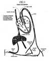
- the fetal circulationis vastly different than the normal adult circulation.
- the blood circulating in a fetusis oxygenated by the placenta, not the developing lungs. Therefore, the fetal circulation directs only a small percentage of the circulating blood to the fetal lungs.
- Most of the circulating bloodis shunted away from the lungs to the peripheral tissues through specialized vessels and foramens that are open ("patent" during fetal life. In most people these specialized structures quickly close after birth. Unfortunately, they sometimes fail to close and create hemodynamic problems that can be fatal if left untreated.
- FIG. 1A diagram showing the blood circulation of a human fetus is illustrated in FIG. 1 .
- the umbilical arteriesbranch off of the iliac arteries and deliver unoxygenated blood to the placenta.
- the fetal bloodtravels through the capillary bed in the placenta and transfers carbon dioxide to the maternal blood and takes oxygen and other nutrients from the maternal blood.
- the umbilical veinreturns oxygenated blood to the fetus. Most of the oxygenated blood from the umbilical vein bypasses the developing liver and travels through a specialized vessel called the ductus venosus to the inferior vena cava and then into the right atrium.
- a good portion of the oxygenated blood from the inferior vena cavais directed across the right atrium and into the left atrium through a specialized curtain like opening in the heart called the foramen ovale.
- the blood from the left atriumthen enters the left ventricle and then into the aorta where it travels to the head and other body tissues delivering the needed oxygen and nutrients.
- the circulatory systemgoes through profound changes.
- the lungsfill with air and the resistance to blood flow into the lungs drastically decreases.
- the corresponding pressure in the right atrium, right ventricle, and pulmonary arteriesalso decrease.
- the decrease in pressure in the right atriumcauses the curtain like opening of the foramen ovale to close, driving more blood into the right ventricle and then to the lungs for oxygenation. Over time, the foramen ovale is replaced with a membrane called the fossa ovalis.
- the decrease in pressure in the pulmonary arteriesreduced the pulmonary arterial pressure to the same as or slightly less than the pressure in the aorta, which stops or reverses the flow through the ductus arteriosus.
- a patent ductus venosus after birthis very rare and almost always fatal.
- a patent ductus arteriosusoccurs in about 1 out of every 5000 births.
- the patent ductus arteriosus once diagnosedis either medically treated or surgically ligated to close the ductus.
- the foramen ovaledoes not seal shut, instead it remains patent.
- Such defectsusually measure 10 mm or more in diameter and occupy one third or more of the length of the atrial septum in echocardiographic four chamber sections.
- the curtain like openingusually remains shut. However, if the pressure in the right atrium increases, such as upon heavy lifting or while performing a Valsalva type maneuver, the curtain like fold of tissue opens and the blood flows from the right atrium to the left atrium.
- clots or plaquecan pass through the venous circulation and into the arterial circulation and then into the brain or other tissues to cause a thromboembolic event like a stroke.
- the clotsmay pass to the arterial side when there is an increase in the pressure in the right atrium. Then the clots travel through the left side of the heart, to the aorta, and then to the brain via the carotid arteries where they cause a stroke and the associated neurological deficits.
- a number of atrial septal defects (ASD) closure deviceshave been developed and investigated in an attempt to develop a nonsurgical, transvenous method of occlusion of ASD. These include the Sideris Buttoned device, the Angel Wing Das device, the atrial septum defect occlusion system (ASDOS) device, the Amplatz Septal Occluder, the CardioSEAL/StarFlex devices, and the Gore/Helix devices. Unfortunately, each of these devices have distinct disadvantages and limitations ranging from the size of the device delivery sheath, ease of implantation, feasibility, safety and effectiveness.
- the Sideris buttoned deviceis made of a polyurethane foam occluder with a Teflon coated wire skeleton, which is positioned within the left atrium, and a polyurethane foam rhomboid shaped counteroccluder with a Teflon coated wire skeleton, which is positioned in the right atrium.
- the major disadvantage with this deviceis the lack of a centering mechanism. For this reason, use of the devices at least two times the size of the stretched ASD is required.
- the “Angel Wings” devicecomprises two square frames made of superelastic Nitinol wire, each square frame having four legs that are interconnected by flexible islets at the comers.
- the wire framesare covered by polyester fibers.
- the deviceis delivered through an 11-13 F Mullins sheath.
- the major disadvantage of using this deviceis the attendant risk of aortic perforation cause by its sharp eyelet comers.
- the Angel Wings devicewas withdrawn from further clinical trials because of this problem.
- the atrial septal defect occlusion system (ASDOS) prosthesis(Microvena Corp., White Bear Lake, Minn.) consists of two umbrellas made of Nitinol and a patch of porous polyurethane attached to the left and right atrial devices.
- the deviceis introduced transvenously over a long veno-arterial guidewire and through an 11 F venous transeptal sheath. While the device is retrievable in the event of malpositioning before release of the device, it requires a complex procedure to implant, and the components are known to have a high incidences of thrombrosis. It is also reported that frame fractures have been detected in 20% of the patients treated with this device.
- the Amplatzer deviceis the subject of U.S. Pat. No. 5,944,738 to Amplatzer, et al.
- This deviceis a saucer-shaped device formed from a mesh of fine Nitinol wires with a central connecting cylinder having a diameter similar to that of the stretched diameter of the defect.
- Thrombosis following implantation of the deviceis induced by three polyester patches.
- the deviceis delivered through a 6-10 F Mullins sheath.
- the primary disadvantage with this deviceis that it is ill-suited for closing fenestrated defects.
- the deviceis a thick, bulky profile which dramatically increases the chances that the device will interfere with the heart's operation.
- Another disadvantageis its known capacity for incomplete endothelialisation with thrombus formation.
- the CardioSEAL.RTM. device(NMT Medical is the subject of U.S. Pat. No. 6,206,907 to Marino, et al.
- This occlusion deviceis comprised of a center section to which stranded wire elastic shape memory fixation devices are attached.
- the fixation deviceshold the occlusion devices in place once it is inserted into an aperture.
- Attached to the fixation devicesare polyvinyl foam sheets which occlude the aperture. While the CardioSEAL is deemed to be relative easy to use, it is reported that, of all the devices, the CardioSEAL device has the highest incidence of arm fractures, which has raised serious issues concerning its safety.
- the CardioSEAL devicelike the Amplatzer device is relatively large, and requiring at least a 10 F or 11 F delivery systems, and an undue amount of hardware within the heart. These characteristics increase the chance that the device will interfere with the heart's operation, lend to residual shunting and/or embolization. The size of the CardioSEAL device also renders it less suitable for small children.
- the STARflex.RTM. device(NMT Medical, Inc.) is an updated version of the CardioSEAL device, which includes a self-centering mechanism consisting of four flexible springs which pass between the two fabric disks. While this added feature may reduce the instances of residual shunting, the aforementioned defects and disadvantages of the CardioSEAL are still a concern.
- the embolic filtering devicecan have an embolic filter.
- the embolic filtercan be made from metal, fiber, and/or polymer.
- the embolic filtercan prevent the passage of emboli through the septal defect.
- the embolic filtering devicecan have a frame. The frame can allow the device to be secured within and or adjacent to the lumen of the septal defect.
- the embolic filteris made by, for example, (1) swaging one end of a piece of tubular mesh at a first end with a first fastener (2) pulling the free end of the mesh over the first fastened end so that it overlaps the first portion; (3) swaging a second, center section of the tubular section to form a 3-dimensional ball-like structure having a first diameter portion with a second fastener; (4) extending the remaining free end of the tubular mesh back over the 3 dimensional ball-like structure of the first and second portions of the tubular mesh; and (4) swaging the free end of the tubular mesh with a third fastener to form an exterior 3-dimensional ball-like structure having a second diameter portion, within which the 3-dimensional ball-like structure of first diameter portion is disposed.
- the meshis removably is secured to at least one or more bases of the frame, and positioned between the arms thereof.
- the bases of the frame and the fasteners which secure the tubular meshcan be collars, for example, having central lumens.
- the aforementioned third-fasteneris insertable into the lumen of at least one of the bases of the frame in order to secure the mesh to the frame.
- the lumens of the fasteners and basesare aligned along a common axis in order that a the embolic filtering device can be loaded onto a guide wire.
- the framecan include at least one base and at least two arms which extend therefrom, between which the mesh is at least partially disposed.
- the framecan be made of metal, fabric and/or a polymer.
- the armsare positioned opposite one another and, in their resting state, are spaced apart from one another.
- the deviceis composed of a shape memory metal, such as nitinol
- the devicecan be collapsed into a catheter tube by compressing the arms of the frame toward one another, causing the length of the device to increase, and the width to decrease. As the device is released from the catheter tube, it reverts to its functional, relaxed state.
- the embolic filtering devicemay also be composed of non-shape memory metals, such as Elgiloy, cobalt chromium, and stainless steel, for example.
- Each armincludes at least one anchor positioned on the arms of the frames.
- the anchorscan either be arcuate or linear in formation, depending on the shape of the patent foramen ovale to be treated, and are of sufficient rigidity to secure the device within the lumen of a septal defect.
- the frame or meshis composed of or coated with a radiopaque material, such as tantalum.
- a radiopaque materialsuch as tantalum.
- the devicemay also be treated with thrombin, collagen, hyluron, or a host growth factor to encourage and facilitate growth of tissue onto the device so as to further secure the device within the septal defect.
- the devicecan also be coated with an anticoagulant to deter formation of blood clots on the surface of the device.
- the meshis composed of at least 96 strands of 0.002" diameter wire braided such that the wires are situated at an angle of 35.degree. relative to the longitudinal axis of the device.
- the interstices created by the braided wiresare small enough such as to effectively filter emboli, thereby preventing emboli from passing through the patent foramen ovale, or other septal defect.
- a method of preventing the passage of emboli between a venous blood pool and an arterial blood poolby delivering the embolic filtering device to within, proximate to and/or adjacent to a passage between a venous blood pool and an arterial blood pool; and securing the device within, proximate to, and/or adjacent to said passage.
- the devicecan be delivered by a catheter to within and/or adjacent to the passage between the venous blood pool and the arterial blood pool.
- Figure 1is a schematic diagram of the fetal circulation
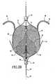
- Figure 2Aillustrates a variation of the embolic filtering device
- Figure 2Billustrates a variation of the embolic filtering device
- Figure 2Cillustrates a top view of the embolic filtering device illustrated in FIG. 2B ;
- Figure 2Dillustrates a variation of the frame of the embolic filtering having two bases
- Figure 3illustrates a variation of the embolic filtering device with a frame having one base
- Figure 4illustrates a variation of the embolic filtering device and delivery mechanism
- Figure 5Aillustrates a variation of the preferred embolic filtering device
- Figure 5B and 5Cillustrate a variation of the embolic filter device within a patent foramen ovale
- Figures 6A and 6Billustrate a variation of the embolic filter device
- Figures 7A and 7Billustrated a variation of the embolic filter device.
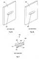
- Figures 8a and 8billustrate various sections of tissue having a tunnel defect.
- Figure 9illustrates the tunnel defect of Figure 8a or 8b .
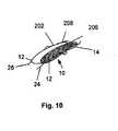
- Figure 10illustrates a variation of a method of deploying a variation of the embolic filtering in a tunnel defect.
- the devicecan treat cardiac defects, such as patent foramen ovale or other atrium septal defects.
- a filtering devicethe device can work by any mechanism including or not including filtering.
- the embolic filtering devicecan act as a scaffold for tissue to grow.
- FIG. 2Aillustrates an embolic filtering device 10 comprising a frame 12 and an embolic filter 14 comprising a mesh of stranded fabric, wire, or combination thereof.
- Any and/or all elements of the embolic filtering device 10, including the frame 12 and the embolic filter 14,can be entirely or partially biodegradable and/or bio-inert (e.g., non-biodegrading). After being deployed in the patient, the embolic filtering device can completely or partially biodegrade.
- the embolic filtering device 10can be made in-part from a first metal that is biodegradable and/or in-part from a second metal that is non-biodegradable, and partially from a first polymer that is biodegradable, and partially from a second polymer that is non-biodegradable.
- the embolic filter 14can be biodegradable and the frame 12 can be non-biodegradable.
- the embolic filter 14can be non-biodegradable and the frame 10 can be biodegradable.
- FIG. 2Dillustrates one frame 12 without embolic filter 14 attached.
- Frame 12can have a first base 16 and a second base 18.
- Each end of arms 20 and 22can be connected to first base 16 and second base 18, such that the lumens of first base 16 and second base 18 are in line with longitudinal axis 24 of frame 12.
- Arms 20 and 22are preferably formed of a shape memory metal, e.g., Nitinol, and formed such that, in the resting state, they are spaced apart from one another.
- a shape memory metale.g., Nitinol
- right anchors 24can extend laterally from each of arms 20 and 22 proximate to first base 16.
- Right anchors 24can be of any shape or formation suitable for delivering embolic filtering device 10 to the desired location and securing it in place.
- right anchors 24are preferably linear or arcuate, and extend outward from frame 12 and away from first base 16, in the direction of second base 18, at an acute angle relative to longitudinal axis 25.
- the desired length of right anchors 24 and the position from which they extend from arms 20 and 22will depend primarily on the size of the passage or defect to be treated. In any event, the right anchors 24 are of sufficient length to securely engage tissue within and/or adjacent to the septal defect.
- right anchors 26when treating a patent foramen ovale, preferably engage tissue within and/or adjacent to the right-atrial opening of the patent foramen ovale. Extending arcuately and/or laterally from the portion of arms 20 and 22 proximate second base 18 are left anchors 26.
- Left anchors 26can be of any shape or formation suitable for delivering embolic filtering device 10 to the desired location and securing it in place; however, it has been found that arcuate or coiled anchors are most suitable for effectively securing the device within the area of interest.
- left anchors 26are of sufficient length to securely engage tissue within and/or adjacent to the septal defect to be treated.
- left anchors 26when treating a patent foramen ovale, left anchors 26 preferably engage tissue within and/or adjacent to the left-atrial opening patent foramen ovale.
- right anchor 24 and left anchor 26are covered with tantalum coil 28, or other radiopaque material, to allow for visualization of the position and location of embolic filtering device 10 after implantation in a subject.
- First base 16 and second base 18 and, for that matter, any portion of device 10can likewise be compromised of radiopaque materials to provide even more visual points of reference in the imagery of embolic filtering device 10.
- FIG. 3illustrates a frame 12 having first base 16, but without second base 18, and shortened arms 20 and 22.
- second base 18By eliminating second base 18, the amount of hardware implanted in the passage to be treated is minimized. Since, as discussed below, second base 18 resides closest to the left atrium of the heart when embolic filtering device 10 is used to treat a patent foramen ovale, eliminating second base 18 minimizes the amount of hardware adjacent to or within the left atrium, decreasing the chance the operation of the left atrium will be comprised, and reducing the surface area upon which blood clots can form.
- Embolic filter 14can be fixedly or removably attached or coupled to frame 12.
- Embolic filter 12can have a plurality of braided wire strands having a predetermined relative orientation and interstitial space between the strands. The number and diameter of the wires used can be selected to achieve the desired density and stiffness of the fabric, and the known size of the emboli sought to be filtered.
- the wire meshcan have at least 96 strands of 0.002" diameter wire, situated at an angle of approximate 35° relative to the longitudinal axis 24.
- Wire strand materialscan be a cobalt-based low thermal expansion alloy (e.g., Elgiloy), nickel-based high temperature high-strength "superalloys” (e.g., Nitinol), nickel-based treatable alloys, a number of different grades of stainless steel, and polymers, including polyester, nylon, polytetrafluoroethylene (PTFE), polyurethane, polyaryletheretherketone (PEEK), and polyglycolic acid (PGA), polylactide (PLA), polyepsilon-caprolactone, polyethylacrylate (PEA), or combinations thereof.
- a cobalt-based low thermal expansion alloye.g., Elgiloy
- nickel-based high temperature high-strength "superalloys”e.g., Nitinol
- nickel-based treatable alloyse.g., a number of different grades of stainless steel
- polymersincluding polyester, nylon, polytetraflu
- Platinum and alloys of platinumcan also be co-braided, co-knitted or co-woven into mesh 14 to assist in determining where mesh is positioned within the patent foramen ovale.
- the wire strandscan be made from a shape memory alloy, NiTi (known as Nitinol) which is an approximately stoichiometric alloy of nickel and titanium and may also include minor amounts of other metals to achieve desired properties.
- NiTiknown as Nitinol
- the frame 12 of device 10, and its components, including base 16, base 18, right arms 24 and left arms 26,can be made from shape memory alloys. Such alloys tend to have a temperature induced phase change which will cause the material to have a preferred configuration which can be fixed by heating the material above a certain transition temperature to induce a phase change in the material. When the alloy is cooled, the alloy can "remember" the shape it was in during the heat treatment and will tend to assume that configuration, unless constrained from doing so.
- NiTi alloy compositionsare known in the art.
- NiTi alloyscan be very elastic (e.g., "superelastic” or "pseudoelastic”). This elasticity allows device 10 to return to a preset configuration after deployment from a catheter or other delivery device.
- the relaxed configurationcan be defined by the shape of the fabric when it is deformed to generally conform to the molding surface of the mold in which it was created.
- the wire standsare manufactured by standard braiding processes and equipment.
- Embolic filter 14can be in the shape of a three-dimensional ball or sphere, as exemplified in FIGS. 2A and 2C .
- the three-dimensional ball or sphereis, for example, made by swaging a first end of the mesh with a first fastener 30, and pushing said first fastener 30 upwards into the lumen of the tubular mesh, to create interior lobes 29.
- a center portion of the meshis then swaged with a second fastener 32, creating an interior embolic filter portion 34.
- first fastener 30, second fastener 32, and interior embolic filter portion 34are in effect situated within exterior embolic filter portion 38.
- Third fastener 36is situated outside of said exterior embolic portion 38.
- fasteners 30, 32 and 36are collars having a central lumen. The lumens of the collars are substantially aligned along a common longitudinal axis 25, and dimensioned to receive a guide wire 40.
- Embolic filter 14is preferably secured to frame 12 by inserting third fastener 36 into the lumen of first base 16 of frame 12.
- third fastener 36 and first base 16can be coupled together, either by a mechanical locking means such as that created by a press fit, a melted polymer interlock, or hot melt adhesive, or by plasma welding.
- Plasma weldingis the preferred coupling method, as it allows first base 16 to be shorter, since no portal is required on the base.
- embolic filter 14resides at least partially between arms 20 and 22, such that the lumens of fasteners 30, 32, and 36 are substantially aligned with the lumens of first base 16 and second base 18 (if employing a frame with second base 18), along longitudinal axis 24.
- a plugcomposed of collagen, fabric, an adhesive, polymer or foam, for example, may be disposed within the aforementioned sphere to further deter the passage of embolic through the mesh.
- FIG. 2Aillustrates an embolic filter 14 that can have a first end comprising at least one lobe-like formation and a second end which tapers inward therefrom.
- a piece of tubular mesh of suitable lengthfor example, is swaged at a first end by a first fastener 30. This first fastened end is then pushed into the lumen of the tubular mesh to form lobes 29. The second end of the mesh is then swaged by a second fastener 32.
- This embodimentis attached to frame 12 by securing first fastener in the lumen of base 16, and securing second fastener 32 in the lumen of base 18.
- fasteners 30 and 32are collars having central lumens. The lumens of the collars are substantially aligned along a common longitudinal axis, and dimensioned to receive a guide wire 40.
- FIG. 5Aillustrates an embolic filtering device 10 having right anchors 24 which are specifically designed to engage the perimeter of the tissue defining the right-atrial opening 23 of the patent foramen ovale, as illustrated in FIG. 5B .
- the ends of right anchors 24 of this embodimentcan reside against or adjacent to the outside of the tissue wall defining the patent foramen ovale.
- Right anchors 24can be slightly longer dimension and at least slightly arcuate in shape to facilitate this methodology.
- the ends of right anchors 24can have or include protective caps 27 at their distal ends.
- Caps 25can be composed of rubber, plastic, or any other suitable material for covering the ends of anchors 27, and may also comprise radiopaque materials, for example, in order to allow post-implant visualization of the location and positioning of anchors 24 after implant.
- Mesh 14can be manufactured in a variety of ways. For example, mesh 14 does not necessarily need to be spherical, or have both an interior and exterior embolic portion, as discussed above. Mesh 14 can be of any shape and dimension suitable to deter the passage of embolic material between a venous blood pool and an arterial blood pool, and can include any number of layers. The interstices between the strands forming mesh 14 can be of sufficient area to filter emboli.
- FIGS. 6A and 6billustrate that arms 20 and 22 can be effectively decoupled from one another, such that the tissue distension function of embolic filtering device 10 is provided separately by each individual legs of the device. This allows embolic filtering device 10 to be more compact, and to better fill gaps and meet the contours of the patent foramen ovale.
- the size of mesh 14need not be large, but can cover only arms 20 and 22 and still be effective in treating patent foramen ovales.
- Device 10provides distinct advantages and improvements over known patent-foramen ovale-treatment devices.
- the elasticity and ball-like structure of mesh 14enables device 10 to treat a patent foramen ovales, or other septal defects, of any shape and dimension with equal effectiveness. This is because mesh 14 is compressible along its entire length. Thus, it does not matter if the patent foramen ovale is fenestrated, as the elasticity of mesh 10 will allow it to conform to the substantially exact shape and dimension of the patent foramen ovale.
- Mesh 14can also be annealed to have a 3-dimensional to help fill any gaps within the patent foramen ovale space. Thus, the post-implant leakage along the perimeter of known devices caused by their inability to accommodate irregular shaped defects is eliminated.
- device 10has substantially less surface compared to known devices, thereby reducing the risk of dangerous blood clot formation on the exterior of the device.
- the interstices between the stands of braided mesh 14 of the present inventionare small enough to effectively filter emboli as soon as device 10 is implanted.
- device 10offers immediate protection against the passage of emboli at the moment of implant.
- the embolic filtering device 10can prevent the passage of emboli between a venous blood pool and an arterial blood pool.
- the method of the inventionis herein exemplified through discussion of a method of treating a patent foramen ovale (PFO).
- the embolic filtering devicecan be used to prevent the passage of emboli between any septal defect and/or arterial venous blood pool and arterial blood pool.
- embolic filtering device 10is loaded into a delivery system 41 comprising a catheter 42, exemplified in FIG. 4 .
- the embolic filtering device 10can be loaded onto a guide wire 40 by inserting the guide wire through the lumens of first base 16, the lumens of fasteners 30, 32, and 36, if employing a frame 12 with second base 18, the lumen of second base 18.
- a pair of forceps 44as exemplified in FIG. 4 , or other grasping device, is used to grasp embolic filtering device 10.
- First base 16can have a recess 46 for receiving forceps 44, such that forceps 44 are positioned within recess 46 to more securely grasp embolic filtering device 10, and to deter embolic filtering device 10 from detaching from forceps 44.
- embolic filtering device 10With embolic filtering device 10 secured by forceps 44 embolic filtering device 10 is pulled into catheter 42. As embolic filtering device 10 is pulled into catheter 42, the force of the catheter walls against first base 16 of frame 12 will force side walls 20 and 22, and left anchors 24 and right anchors 26 inward toward one another. Embolic filtering device 10 will gradually collapse as it is pulled into catheter 42.
- embolic filtering device 10is delivered to the patent foramen ovale, or other passage between a venous blood pool or arterial blood pool, to be treated.
- the distal end of catheter 42is extended through the patent foramen ovale from the right atrial side to the left atrial side.
- forceps 44are used to withdraw embolic filtering device 10 from catheter 42.
- embolic filtering device 10will gradually expand from its collapsed position and into its memorized shape and/or in conformance to the shape and dimension of the patent foramen ovale being treated.
- embolic filtering device 10With the distal end of catheter 42 positioned in the left atrium, adjacent to the patent foramen ovale, embolic filtering device 10 is withdrawn from catheter 42, while catheter 42 is slowly pulled back through the patent foramen ovale in the direction of the right atrium. Left anchors 26 can be withdrawn first. As catheter 42 is pulled back, left anchors 26 can securely engage the walls defining the patent foramen ovale, for example, the tissue defining the perimeter of the left-atrial opening 23 of the patent foramen ovale, as shown in FIG. 5C .
- embolic filter device 10As catheter 42 is pulled back further, the engagement of left anchors 26 onto the tissue defining the perimeter of the left-atrial opening 23 of arms 20 and 22 will prevent embolic filter device 10 from being pulled through the patent foramen ovale, and embolic filter 14 can emerge within the patent foramen ovale, and can gradually expand apart from one another in returning to the shape memorized orientation. As arms 20 and 22 expand apart from one another, pressure will be exerted onto the tissue defining the lumen of the patent foramen ovale, thereby acting as a tissue distension device. The tissue defining the patent foramen ovale will naturally press inward against mesh 14, in effect squeezing the device within the patent foramen ovale.
- right anchors 24will emerge and, as they expand to their memorized shape, will also forcibly engage, for example, the walls defining the patent foramen ovale, or the perimeter of the tissue defining right atrial opening 27 of the patent foramen ovale. If using the embolic filter device illustrated in FIG. 5A , for example, right anchors 24 will engage the tissue defining the outside perimeter defining the right-atrial opening 27 of the patent-foramen ovale, as illustrated in FIG. 5B .
- embolic filter 14In its memorized shape, embolic filter 14 should be sized to engage the walls defining the patent foramen ovale with sufficient force to prevent emboli from passing between the exterior of the embolic filter 14 and the walls of defining the patent foramen ovale. Further, the force created from blood flowing from the right atrium to the left atrium against right anchors 24 facilitates the securing of right anchors 24, and helps prevent embolic filtering device 10 from becoming dislodged from its intended position.
- the devicecan be secured in place by adhesives, sutures, hooks, barbs, or other such means.
- frame 12 and/or mesh 14can be coated with known drugs suitable for that purpose.
- Non-pharmacological methodscan also be used to promote healing, including ultrasound, radiofrequency, radiation, mechanical vibration, other non-pharmacological healing method, or combinations thereof.
- embolic filtering device 10Prior to disengaging embolic filtering device 10 from forceps 44 and removing catheter 42 from the subject, known radiological techniques can be employed to insure that embolic filtering device 10 is properly positioned and secured within the patent foramen ovale. If the position of embolic filtering device 10 needs to be altered, forceps 44, while still secured to embolic filtering device 10, can be used to reposition embolic filtering device 10; otherwise, forceps 44 are disengaged from embolic filtering device 10, and forceps 44, catheter 42, and guide wire 40 are withdrawn. Should embolic filter device 10 later become disengaged, disoriented, damaged or otherwise need to be removed, forceps 44 can be used to easily reposition or recover embolic filter device 10, as necessary. To facilitate the ease by which embolic filter device 10 is repositioned or recovered, base 16 can be coated with a suitable material to deter tissue from covering recess 46.
- emboliare effectively filtered by embolic filtering device 10. Since blood travels from the direction of the right atrium to the left atrium, the portion of embolic filter 14 having a higher density of mesh, e.g., lobes 29 and/or interior embolic filter portion 34, are positioned on the right atria side to decrease the chances that emboli will penetrate into the left atrium.
- the design of embolic filtering device 10, however,is such that if emboli pass through the right side of embolic filter 14, there is still a significant chance that the portion of embolic filter 14 positioned on the left atrial side will prevent the emboli from passing into the left atrium.
- embolic filtering device 10can be treated with materials to promote thrombrosis, tissue in-growth, or adhesions. Embolic filter 14 can also be treated with anticoagulants to discourage blood clot formation on the device 10.
- the primary function of frame 12is to facilitate the delivery, positioning and securing of the embolic filter 14 within and/or adjacent to a passage between a venous blood pool and an arterial blood pool. It should be appreciated, however, that embolic filter 14 can be employed by itself, without frame 12, by securing embolic filter 14 by other means, e.g. sutures, hooks, etc., to deter the passage of emboli through a passage between a venous blood pool and an arterial blood pool. Further, embolic filter 14 can be of virtually any shape, spherical, round, oval or flat, so long as it retains its ability to filter emboli.
- an embolic filter device 100composed of a mesh 112 and a frame 114, to which mesh 112 is attached.
- Mesh 112can be composed of any suitable material, including fabric, metal (e.g. shape memory metal or non-shape memory metal), or polymer, and can be of any shape (e.g., round, oval, or flat) or size suitable for the opening to be treated.
- Frame 114can also be composed of any suitable material.
- frame 114can be composed of fabric, if rigidity is not required to support the opening to be treated.
- frame 114can be composed of plastic, metal or the like, so as to act as a stent to give support to the orifice through which the passage of embolic is to be deterred.
- mesh 112 and/or frame 114can be absorbable or non-absorbable.
- embolic filtering device 110can block the passage between a venous blood pool and an arterial blood pool.
- embolic filtering device 100can be attached to tissue adjacent to the patent foramen ovale by for example, sutures, barbs, hooks, glue, or any other suitable attaching means 116 to, in effect, create a screen covering the right atrial and/or left atrial openings, and/or within the lumen of the patent foramen ovale.
- the attaching means 116can be on frame 114.
- the attaching means 116can be placed at any suitable location on embolic filter device 100.
- embolic filtering device 110effectively deters the passage of emboli from the right atrium to the left atrium via the patent foramen ovale.
- Embolic filter devicemay be delivered either percutaneously, surgically, or via a catheter, depending on the area to be treated.
- the frame 12can be made from a biodegradable and a non-biodegradable polymer.
- the frame 12can be made from a polymer and/or a metal.
- the frame 12can be made from a biodegradable, a non-biodegradable polymer and a metal.
- the embolic filter 14can be made from a non-woven material.
- the embolic filter 14can be made from felt, paper, scrim cloth, a melted material, a blown material, film (e.g., textured film, slit film), a single layer of material, multiple layers of material, individual filaments, individual yarns, individual threads, random fibrils, gels, swelling polymers, foams, textured threads (e.g., hairy, bulky, tangled bundles), coils (e.g., 3-dimensional coil shapes), or combinations thereof.
- the embolic filter 14can be made from biodegradable polymer thread and/or non-biodegradable polymer thread.
- the embolic filter 14can be made from thread that is made from mixed biodegradable and non-biodegradable polymer.
- the embolic filter 14can be made from polymer threads and/or metal threads.
- the embolic filter 14can be made from Nitinol thread mixed with PET and/or PGA thread.
- the embolic filter 14can be made from thread that is made from mixed polymer (i.e., biodegradable and/or non-biodegradable) and metal.
- the embolic filter 14can be made from thread made from Nitinol mixed with PET and/or PGA.
- the embolic filter device 10can be configured to stop motion (i.e., anchoring), after deployment, of the embolic filter device 10 within the biological tunnel to which embolic filter device 10 is deployed.
- the anchoringcan stop migration of the embolic filtering device 10.
- Frictioncan anchor the embolic filtering device 10.
- Tissue of the biological tunnelcan bind to the frame 12.
- the bindingcan be accomplished by ingrowth of the tissue into or around the frame 12.
- the bindingcan be accomplished by surface friction (e.g., static and/or dynamic) between the frame 12 and the tissue.
- Tissue of the biological tunnelcan bind to the embolic filter 14 (i.e., shroud).
- the bindingcan be accomplished by ingrowth of the tissue into or around the embolic filter 14.
- the bindingcan be accomplished by surface friction (e.g., static and/or dynamic) between the embolic filter 14 and the tissue.
- All or part of the surfaces of the embolic filter device 10, such as the frame 12 and/or the embolic filter 14,can be increased with surface textures (e.g., knurling, pebbling, ridging, roping, or combinations thereof), encrusting (e.g., with granular materials, such as diamond, sand, the material of the surface of the embolic filter device 10, any other material listed herein, or combinations thereof), increased radial or planar forces (e.g., squeezing the septal tissue between arms of the embolic filter device 10), vacuum (e.g., by an active vacuum, or active or passive suction cups, such as micro suction cups), 3-dimensional shapes such as coils used to help grab the tissue, or combinations thereof.
- surface texturese.g., knurling, pebbling, ridging, roping, or combinations thereof
- encrustinge.g., with granular materials, such as diamond, sand, the material of the surface of the embolic
- the embolic filter device 10, for example on the frame 12 and/or embolic filter 14,can have a bioadhesive.
- the bioadhesivecan be a glue or a drug.
- the bioadhesivecan be configured to attach to the tissue.
- the embolic filter device 10can be adhered or otherwise bonded to the tissue by application of heat, RF energy, ultrasound energy, magnetic resonance (e.g., MRI), x-ray radiation, or combinations thereof.
- the embolic filter device 10can have one or more anchors.
- the anchorcan be an active anchor.
- the active anchorcan move actively (e.g., a spring-loaded barb) when deployed.
- the active anchorcan pierce tissue with or without barbs when the embolic filter device 10 is deployed.
- the anchorcan be a passive anchor.
- the passive anchorcan be a loop, hook, tooth, tab, finger of material used to grab or loop over tissue or work into nooks and crannies within tunnels, or combinations thereof.
- the embolic filter device 10can be manufactured from a round tube or flat sheet of material.
- the embolic filter device 10can be made by laser cutting, weaving, stamping, die-cutting, molding, or made in any combination of methods thereof.
- Figure 8aillustrates a section of tissue 200 that can have a tunnel defect 202 passing through the tissue 200.
- the tunnel defect 202can be substantially perpendicular to the face of the tissue 200.
- the tunnel defect 202can be an atrial septal defect (ASD).
- Figure 8billustrates that the tunnel defect 202 can be at a steep angle or substantially parallel to the face of the tissue 200.
- the tunnel defect 202can be a patent foramen ovale (PFO).
- Figure 9illustrates that the tunnel defect 202 can have a defect front face 204 and a defect back face (not shown).
- a defect front lip 206can be defined by the perimeter of the defect front face 204.
- a defect back lip 208can be defined by the perimeter of the defect back face.
- the tunnel defect 202can have a defect height 210, a defect depth 212 and a defect width 214.
- the embolic filtering device 10can be used to treat any tunnel defect.
- Figure 10illustrates that the embolic filtering device 10 can be deployed in the tunnel defect 202. After deployment, the embolic filtering device 10 can be located entirely, substantially, or partially within the tunnel defect 202.
- the frame 12can be in substantial contact with wall of the tunnel defect 202.
- the embolic filter 14can be in substantial contact with wall of the tunnel defect 202.
- the embolic filtering device 10can stop blood flow through the tunnel defect 202 quickly or slowly (i.e., time effect).
- the embolic filtering device 10can partially, substantially or completely impede or stop fluid (e.g., blood) and solid (e.g., blood clot) flow through the tunnel defect 202 at the time of deployment.
- the embolic filtering device 10can partially, substantially or gradually increasingly impede or stop fluid (e.g., blood) and solid (e.g., blood clot) flow through the tunnel defect 202 as time progresses after deployment.
- the tissue 200 around the tunnel defect 202can grow or otherwise heal onto the embolic filtering device 10, for example onto the frame 12 and/or the embolic filter 14.
- the tissue grown or healed onto the embolic filtering device 10can further impede or stop fluid (e.g., blood) and solid (e.g., clot) flow through the tunnel defect 202.
- the embolic filtering device 10for example the frame 12 and/or embolic filter 14, can plug the tunnel defect 202.
- any or all elements of the embolic filtering device and/or other devices or apparatuses described hereincan be made from, for example, a single or multiple stainless steel alloys, nickel titanium alloys (e.g., Nitinol), cobalt-chrome alloys (e.g., ELGILOY® from Elgin Specialty Metals, Elgin, IL; CONICHROME® from Carpenter Metals Corp., Wyomissing, PA), nickel-cobalt alloys (e.g., MP35N® from Magellan Industrial Trading Company, Inc., Westport, CT), molybdenum alloys (e.g., molybdenum TZM alloy, for example as disclosed in International Pub. No.
- nickel titanium alloyse.g., Nitinol
- cobalt-chrome alloyse.g., ELGILOY® from Elgin Specialty Metals, Elgin, IL; CONICHROME® from Carpenter Metals Corp., Wyomissing, PA
- WO 03/082363 A2published 9 October 2003 , which is herein incorporated by reference in its entirety
- tungsten-rhenium alloysfor example, as disclosed in International Pub. No. WO 03/082363
- polymerssuch as polyethylene teraphathalate (PET), polyester (e.g., DACRON® from E. I.
- polypropylenepolypropylene
- aromatic polyesterssuch as liquid crystal polymers (e.g., Vectran, from Kuraray Co., Ltd., Tokyo, Japan), ultra high molecular weight polyethylene (i.e., extended chain, high-modulus or high-performance polyethylene) fiber and/or yam (e.g., SPECTRA® Fiber and SPECTRA® Guard, from Honeywell International, Inc., Morris Township, NJ, or DYNEEMA® from Royal DSM N.V., Heerlen, the Netherlands), polytetrafluoroethylene (PTFE), expanded PTFE (ePTFE), polyether ketone (PEK), polyether ether ketone (PEEK), poly ether ketone ketone (PEKK) (also poly aryl ether ketone ketone), nylon, polyether-block co-polyamide polymers (e.g., PEBAX® from ATOFINA, Paris, France), aliphatic polyether polyurethane
- liquid crystal polymerse.
- embolic filtering device and/or other devices or apparatuses described hereincan be, have, and/or be completely or partially coated with agents and/or a matrix a matrix for cell ingrowth or used with a fabric, for example a covering (not shown) that acts as a matrix for cell ingrowth.
- the matrix and/or fabriccan be, for example, polyester (e.g., DACRON® from E. I. Du Pont de Nemours and Company, Wilmington, DE), polypropylene, PTFE, ePTFE, nylon, extruded collagen, silicone or combinations thereof.
- the embolic filtering device and/or elements of the embolic filtering device and/or other devices or apparatuses described herein and/or the fabriccan be filled, coated, layered and/or otherwise made with and/or from cements, fillers, glues, and/or an agent delivery matrix known to one having ordinary skill in the art and/or a therapeutic and/or diagnostic agent. Any of these cements and/or fillers and/or glues can be osteogenic and osteoinductive growth factors.
- cements and/or fillersexamples include bone chips, demineralized bone matrix (DBM), calcium sulfate, coralline hydroxyapatite, biocoral, tricalcium phosphate, calcium phosphate, polymethyl methacrylate (PMMA), biodegradable ceramics, bioactive glasses, hyaluronic acid, lactoferrin, bone morphogenic proteins (BMPs) such as recombinant human bone morphogenetic proteins (rhBMPs), other materials described herein, or combinations thereof.
- DBMdemineralized bone matrix
- PMMApolymethyl methacrylate
- BMPsbone morphogenic proteins
- rhBMPsrecombinant human bone morphogenetic proteins
- the agents within these matricescan include any agent disclosed herein or combinations thereof, including radioactive materials; radiopaque materials; cytogenic agents; cytotoxic agents; cytostatic agents; thrombogenic agents, for example polyurethane, cellulose acetate polymer mixed with bismuth trioxide, and ethylene vinyl alcohol; lubricious, hydrophilic materials; phosphor cholene; anti-inflammatory agents, for example non-steroidal anti-inflammatories (NSAIDs) such as cyclooxygenase-1 (COX-1) inhibitors (e.g., acetylsalicylic acid, for example ASPIRIN® from Bayer AG, Leverkusen, Germany; ibuprofen, for example ADVIL® from Wyeth, Collegeville, PA; indomethacin; mefenamic acid), COX-2 inhibitors (e.g., VIOXX® from Merck & Co., Inc., Whitehouse Station, NJ; CELEBREX® from Pharmacia Corp
- Any elements described herein as singularcan be pluralized (i.e., anything described as "one” can be more than one).
- Any species element of a genus elementcan have the characteristics or elements of any other species element of that genus.
- the above-described configurations, elements or complete assemblies and methods and their elements for carrying out the invention, and variations of aspects of the inventioncan be combined and modified with each other in any combination.
Landscapes
- Health & Medical Sciences (AREA)
- Life Sciences & Earth Sciences (AREA)
- Surgery (AREA)
- Biomedical Technology (AREA)
- General Health & Medical Sciences (AREA)
- Engineering & Computer Science (AREA)
- Heart & Thoracic Surgery (AREA)
- Veterinary Medicine (AREA)
- Public Health (AREA)
- Animal Behavior & Ethology (AREA)
- Medical Informatics (AREA)
- Vascular Medicine (AREA)
- Nuclear Medicine, Radiotherapy & Molecular Imaging (AREA)
- Molecular Biology (AREA)
- Reproductive Health (AREA)
- Cardiology (AREA)
- Oral & Maxillofacial Surgery (AREA)
- Transplantation (AREA)
- Surgical Instruments (AREA)
- Apparatus For Radiation Diagnosis (AREA)
- Measuring Volume Flow (AREA)
- Paper (AREA)
Abstract
Description
- This application claims the benefit of
U.S. Provisional Application Nos. 60/860,393, filed 20 November 2006 60/866,847, filed 21 November 2006 - The present invention relates generally to a device and method for preventing the undesired passage of emboli from a venous blood pool to an arterial blood pool. The invention relates especially to a device and method for treating certain cardiac defects, especially patent foramen ovales and other septal defects through the use of an embolic filtering device capable of instantaneously deterring the passage of emboli from the moment of implantation.
- The fetal circulation is vastly different than the normal adult circulation. The blood circulating in a fetus is oxygenated by the placenta, not the developing lungs. Therefore, the fetal circulation directs only a small percentage of the circulating blood to the fetal lungs. Most of the circulating blood is shunted away from the lungs to the peripheral tissues through specialized vessels and foramens that are open ("patent" during fetal life. In most people these specialized structures quickly close after birth. Unfortunately, they sometimes fail to close and create hemodynamic problems that can be fatal if left untreated.
- A diagram showing the blood circulation of a human fetus is illustrated in
FIG. 1 . The umbilical arteries branch off of the iliac arteries and deliver unoxygenated blood to the placenta. The fetal blood travels through the capillary bed in the placenta and transfers carbon dioxide to the maternal blood and takes oxygen and other nutrients from the maternal blood. The umbilical vein returns oxygenated blood to the fetus. Most of the oxygenated blood from the umbilical vein bypasses the developing liver and travels through a specialized vessel called the ductus venosus to the inferior vena cava and then into the right atrium. A good portion of the oxygenated blood from the inferior vena cava is directed across the right atrium and into the left atrium through a specialized curtain like opening in the heart called the foramen ovale. The blood from the left atrium then enters the left ventricle and then into the aorta where it travels to the head and other body tissues delivering the needed oxygen and nutrients. - The small amount of blood entering the right atrium that does not pass through the foramen ovale, most of which comes from the superior vena cava, flows into the right ventricle and then gets pumped into the pulmonary trunk and pulmonary arteries. Some of this blood is pumped into the developing lungs. However, the fetal lungs are collapsed which causes a high resistance to blood flow. Another specialized vessel, called the ductus arteriosus, is a vessel that connects the high pressure pulmonary artery to the lower pressure aorta. Therefore, most of the blood in the pulmonary artery flows into the lower pressure aorta through this specialized vessel.
- Upon birth, the circulatory system goes through profound changes. The flow through the umbilical arteries and umbilical vein stops and consequently the flow through the musculature around the ductus venosus constricts and the blood flow through the ductus venosus stops. The lungs fill with air and the resistance to blood flow into the lungs drastically decreases. The corresponding pressure in the right atrium, right ventricle, and pulmonary arteries also decrease. The decrease in pressure in the right atrium causes the curtain like opening of the foramen ovale to close, driving more blood into the right ventricle and then to the lungs for oxygenation. Over time, the foramen ovale is replaced with a membrane called the fossa ovalis. Similarly, the decrease in pressure in the pulmonary arteries reduced the pulmonary arterial pressure to the same as or slightly less than the pressure in the aorta, which stops or reverses the flow through the ductus arteriosus. Once the muscular tissue of the ductus arteriosus is perfused with well oxygenated blood, the muscle begins to constrict and close the ductus arteriosus. The ductus arteriosus normally closes within about one week of life.
- Usually over time, the unique openings of the fetal circulation become obliterated and a solid mass of tissue forms where these opening once were. However, in some people the opening remain. A patent ductus venosus after birth is very rare and almost always fatal. A patent ductus arteriosus occurs in about 1 out of every 5000 births. The patent ductus arteriosus once diagnosed is either medically treated or surgically ligated to close the ductus. In about one of four people, the foramen ovale does not seal shut, instead it remains patent. Such defects usually measure 10 mm or more in diameter and occupy one third or more of the length of the atrial septum in echocardiographic four chamber sections. Since the pressure in the left atrium is about two to four mm Hg greater than the pressure in the right atrium, the curtain like opening usually remains shut. However, if the pressure in the right atrium increases, such as upon heavy lifting or while performing a Valsalva type maneuver, the curtain like fold of tissue opens and the blood flows from the right atrium to the left atrium.
- Studies have shown that adults with strokes of unknown origin, i.e., cryptogenic strokes, have about twice the normal rate of patent foramen ovales than the normal population. Although there is a correlation between strokes and patent foramen ovales, it is currently unknown why this correlation exists. It is theorized that blood clots and plaque that have formed in the peripheral venous circulation (in the legs for example) break off and travel to the heart. Normally, the clots and plaque get delivered to the lungs where it is trapped and usually cause no harm to the patient. Patients with a patent foramen ovale, however, have a potential opening that the clots or plaque can pass through the venous circulation and into the arterial circulation and then into the brain or other tissues to cause a thromboembolic event like a stroke. The clots may pass to the arterial side when there is an increase in the pressure in the right atrium. Then the clots travel through the left side of the heart, to the aorta, and then to the brain via the carotid arteries where they cause a stroke and the associated neurological deficits.
- A number of atrial septal defects (ASD) closure devices have been developed and investigated in an attempt to develop a nonsurgical, transvenous method of occlusion of ASD. These include the Sideris Buttoned device, the Angel Wing Das device, the atrial septum defect occlusion system (ASDOS) device, the Amplatz Septal Occluder, the CardioSEAL/StarFlex devices, and the Gore/Helix devices. Unfortunately, each of these devices have distinct disadvantages and limitations ranging from the size of the device delivery sheath, ease of implantation, feasibility, safety and effectiveness. The Sideris buttoned device is made of a polyurethane foam occluder with a Teflon coated wire skeleton, which is positioned within the left atrium, and a polyurethane foam rhomboid shaped counteroccluder with a Teflon coated wire skeleton, which is positioned in the right atrium. The major disadvantage with this device is the lack of a centering mechanism. For this reason, use of the devices at least two times the size of the stretched ASD is required. (Sievert H. Koppeler P. Rux S: Percutaneous closure of 176 interarterial defects in adults with different occlusion devices--6 years of experience [abstract],J. Am. Coll. Cardiol 1999, 33:51 9A.) Consequently, closure of defects may become difficult because the required size may be too large for the atrial septum to accommodate, or the device may impinge critical structures. There are also reports that the retrieval of the Sideris button device after incorrect deployment is difficult. (See, e.g.,Rigby, Michael L., The Era of Transcatheter Closure of Atrial Septal Defects, Heart; 81:227-228 (1999)).
- The "Angel Wings" device comprises two square frames made of superelastic Nitinol wire, each square frame having four legs that are interconnected by flexible islets at the comers. The wire frames are covered by polyester fibers. There is a conjoint suture ring of the right and atrial discs, which allow self centering on deployment. The device is delivered through an 11-13 F Mullins sheath. The major disadvantage of using this device is the attendant risk of aortic perforation cause by its sharp eyelet comers. In fact, the Angel Wings device was withdrawn from further clinical trials because of this problem. (Syamaxundar Rao, P., M.D., Summary and Comparison of Atrial Septal Defect Closure Devices, Current Interventional Cardiology Reports 2000, 2:367-376 (2000)). The device is also ill-suited for treating fenestrated defects.
- The atrial septal defect occlusion system (ASDOS) prosthesis (Microvena Corp., White Bear Lake, Minn.) consists of two umbrellas made of Nitinol and a patch of porous polyurethane attached to the left and right atrial devices. The device is introduced transvenously over a long veno-arterial guidewire and through an 11 F venous transeptal sheath. While the device is retrievable in the event of malpositioning before release of the device, it requires a complex procedure to implant, and the components are known to have a high incidences of thrombrosis. It is also reported that frame fractures have been detected in 20% of the patients treated with this device.
- The Amplatzer device is the subject of
U.S. Pat. No. 5,944,738 to Amplatzer, et al. This device is a saucer-shaped device formed from a mesh of fine Nitinol wires with a central connecting cylinder having a diameter similar to that of the stretched diameter of the defect. Thrombosis following implantation of the device is induced by three polyester patches. The device is delivered through a 6-10 F Mullins sheath. The primary disadvantage with this device is that it is ill-suited for closing fenestrated defects. Moreover, the device is a thick, bulky profile which dramatically increases the chances that the device will interfere with the heart's operation. Another disadvantage is its known capacity for incomplete endothelialisation with thrombus formation. - The CardioSEAL.RTM. device (NMT Medical is the subject of
U.S. Pat. No. 6,206,907 to Marino, et al. This occlusion device is comprised of a center section to which stranded wire elastic shape memory fixation devices are attached. The fixation devices hold the occlusion devices in place once it is inserted into an aperture. Attached to the fixation devices are polyvinyl foam sheets which occlude the aperture. While the CardioSEAL is deemed to be relative easy to use, it is reported that, of all the devices, the CardioSEAL device has the highest incidence of arm fractures, which has raised serious issues concerning its safety. Moreover, the CardioSEAL device, like the Amplatzer device is relatively large, and requiring at least a 10 F or 11 F delivery systems, and an undue amount of hardware within the heart. These characteristics increase the chance that the device will interfere with the heart's operation, lend to residual shunting and/or embolization. The size of the CardioSEAL device also renders it less suitable for small children. - The STARflex.RTM. device (NMT Medical, Inc.) is an updated version of the CardioSEAL device, which includes a self-centering mechanism consisting of four flexible springs which pass between the two fabric disks. While this added feature may reduce the instances of residual shunting, the aforementioned defects and disadvantages of the CardioSEAL are still a concern.
- In view of these drawbacks and related-risks, the method of choice to close a patent foramen ovale is still open heart surgery and ligation of the foramen ovale to close it. Surgery, however, is obviously associated with the usually risks of general anesthesia, open heart procedures, infections, etc. Thus, there is a need for a safe, cost-effective, and easily implantable device and method for preventing the passage of emboli from an arterial blood pool and a venous blood pool which is not subject to the defects and disadvantages of known devices.
- There is hereinafter described and illustrated an embolic filtering apparatus for treating septal defects, including patent foramen ovales. The embolic filtering device can have an embolic filter. The embolic filter can be made from metal, fiber, and/or polymer. The embolic filter can prevent the passage of emboli through the septal defect. The embolic filtering device can have a frame. The frame can allow the device to be secured within and or adjacent to the lumen of the septal defect.
- The embolic filter is made by, for example, (1) swaging one end of a piece of tubular mesh at a first end with a first fastener (2) pulling the free end of the mesh over the first fastened end so that it overlaps the first portion; (3) swaging a second, center section of the tubular section to form a 3-dimensional ball-like structure having a first diameter portion with a second fastener; (4) extending the remaining free end of the tubular mesh back over the 3 dimensional ball-like structure of the first and second portions of the tubular mesh; and (4) swaging the free end of the tubular mesh with a third fastener to form an exterior 3-dimensional ball-like structure having a second diameter portion, within which the 3-dimensional ball-like structure of first diameter portion is disposed.
- The mesh is removably is secured to at least one or more bases of the frame, and positioned between the arms thereof. The bases of the frame and the fasteners which secure the tubular mesh can be collars, for example, having central lumens. The aforementioned third-fastener is insertable into the lumen of at least one of the bases of the frame in order to secure the mesh to the frame. The lumens of the fasteners and bases are aligned along a common axis in order that a the embolic filtering device can be loaded onto a guide wire.
- The frame can include at least one base and at least two arms which extend therefrom, between which the mesh is at least partially disposed. The frame can be made of metal, fabric and/or a polymer. The arms are positioned opposite one another and, in their resting state, are spaced apart from one another. When the device is composed of a shape memory metal, such as nitinol, the device can be collapsed into a catheter tube by compressing the arms of the frame toward one another, causing the length of the device to increase, and the width to decrease. As the device is released from the catheter tube, it reverts to its functional, relaxed state. The embolic filtering device may also be composed of non-shape memory metals, such as Elgiloy, cobalt chromium, and stainless steel, for example. Each arm includes at least one anchor positioned on the arms of the frames. The anchors can either be arcuate or linear in formation, depending on the shape of the patent foramen ovale to be treated, and are of sufficient rigidity to secure the device within the lumen of a septal defect.
- To allow for non-invasive visualization of the device within a subject at least a portion of the frame or mesh is composed of or coated with a radiopaque material, such as tantalum. The device may also be treated with thrombin, collagen, hyluron, or a host growth factor to encourage and facilitate growth of tissue onto the device so as to further secure the device within the septal defect. The device can also be coated with an anticoagulant to deter formation of blood clots on the surface of the device.
- In an exemplary embodiment, the mesh is composed of at least 96 strands of 0.002" diameter wire braided such that the wires are situated at an angle of 35.degree. relative to the longitudinal axis of the device. The interstices created by the braided wires are small enough such as to effectively filter emboli, thereby preventing emboli from passing through the patent foramen ovale, or other septal defect.
- In another aspect of the invention, provided is a method of preventing the passage of emboli between a venous blood pool and an arterial blood pool by delivering the embolic filtering device to within, proximate to and/or adjacent to a passage between a venous blood pool and an arterial blood pool; and securing the device within, proximate to, and/or adjacent to said passage. The device can be delivered by a catheter to within and/or adjacent to the passage between the venous blood pool and the arterial blood pool.
Figure 1 is a schematic diagram of the fetal circulation;Figure 2A illustrates a variation of the embolic filtering device;Figure 2B illustrates a variation of the embolic filtering device;Figure 2C illustrates a top view of the embolic filtering device illustrated inFIG. 2B ;Figure 2D illustrates a variation of the frame of the embolic filtering having two bases;Figure 3 illustrates a variation of the embolic filtering device with a frame having one base;Figure 4 illustrates a variation of the embolic filtering device and delivery mechanism;Figure 5A illustrates a variation of the preferred embolic filtering device;Figure 5B and 5C illustrate a variation of the embolic filter device within a patent foramen ovale;Figures 6A and 6B illustrate a variation of the embolic filter device; andFigures 7A and 7B illustrated a variation of the embolic filter device.Figures 8a and 8b illustrate various sections of tissue having a tunnel defect.Figure 9 illustrates the tunnel defect ofFigure 8a or 8b .Figure 10 illustrates a variation of a method of deploying a variation of the embolic filtering in a tunnel defect.- Disclosed are methods and apparatuses for preventing the passage of emboli between a venous blood pool and an arterial blood pools using devices for creating a barrier to the conducting of emboli at a passage between a venous blood pool and an arterial blood pool. The device can treat cardiac defects, such as patent foramen ovale or other atrium septal defects. Although referred to as a filtering device, the device can work by any mechanism including or not including filtering. For example, the embolic filtering device can act as a scaffold for tissue to grow.
FIG. 2A illustrates anembolic filtering device 10 comprising aframe 12 and anembolic filter 14 comprising a mesh of stranded fabric, wire, or combination thereof. Any and/or all elements of theembolic filtering device 10, including theframe 12 and theembolic filter 14, can be entirely or partially biodegradable and/or bio-inert (e.g., non-biodegrading). After being deployed in the patient, the embolic filtering device can completely or partially biodegrade. For example, theembolic filtering device 10 can be made in-part from a first metal that is biodegradable and/or in-part from a second metal that is non-biodegradable, and partially from a first polymer that is biodegradable, and partially from a second polymer that is non-biodegradable. For example, theembolic filter 14 can be biodegradable and theframe 12 can be non-biodegradable. Also for example, theembolic filter 14 can be non-biodegradable and theframe 10 can be biodegradable.FIG. 2D illustrates oneframe 12 withoutembolic filter 14 attached.Frame 12 can have afirst base 16 and asecond base 18. Each end ofarms first base 16 andsecond base 18, such that the lumens offirst base 16 andsecond base 18 are in line withlongitudinal axis 24 offrame 12.Arms - Referring to
FIG. 2A , right anchors 24 can extend laterally from each ofarms first base 16. Right anchors 24 can be of any shape or formation suitable for deliveringembolic filtering device 10 to the desired location and securing it in place. In a preferred embodiment, right anchors 24 are preferably linear or arcuate, and extend outward fromframe 12 and away fromfirst base 16, in the direction ofsecond base 18, at an acute angle relative tolongitudinal axis 25. The desired length ofright anchors 24 and the position from which they extend fromarms arms second base 18 are left anchors 26. Left anchors 26 can be of any shape or formation suitable for deliveringembolic filtering device 10 to the desired location and securing it in place; however, it has been found that arcuate or coiled anchors are most suitable for effectively securing the device within the area of interest. As withright anchors 24, left anchors 26 are of sufficient length to securely engage tissue within and/or adjacent to the septal defect to be treated. For example, when treating a patent foramen ovale, leftanchors 26 preferably engage tissue within and/or adjacent to the left-atrial opening patent foramen ovale. In a preferred embodiment,right anchor 24 and leftanchor 26 are covered withtantalum coil 28, or other radiopaque material, to allow for visualization of the position and location ofembolic filtering device 10 after implantation in a subject.First base 16 andsecond base 18 and, for that matter, any portion ofdevice 10 can likewise be compromised of radiopaque materials to provide even more visual points of reference in the imagery ofembolic filtering device 10. FIG. 3 illustrates aframe 12 havingfirst base 16, but withoutsecond base 18, and shortenedarms second base 18, the amount of hardware implanted in the passage to be treated is minimized. Since, as discussed below,second base 18 resides closest to the left atrium of the heart whenembolic filtering device 10 is used to treat a patent foramen ovale, eliminatingsecond base 18 minimizes the amount of hardware adjacent to or within the left atrium, decreasing the chance the operation of the left atrium will be comprised, and reducing the surface area upon which blood clots can form.Embolic filter 14 can be fixedly or removably attached or coupled toframe 12.Embolic filter 12 can have a plurality of braided wire strands having a predetermined relative orientation and interstitial space between the strands. The number and diameter of the wires used can be selected to achieve the desired density and stiffness of the fabric, and the known size of the emboli sought to be filtered. The wire mesh can have at least 96 strands of 0.002" diameter wire, situated at an angle of approximate 35° relative to thelongitudinal axis 24. Wire strand materials can be a cobalt-based low thermal expansion alloy (e.g., Elgiloy), nickel-based high temperature high-strength "superalloys" (e.g., Nitinol), nickel-based treatable alloys, a number of different grades of stainless steel, and polymers, including polyester, nylon, polytetrafluoroethylene (PTFE), polyurethane, polyaryletheretherketone (PEEK), and polyglycolic acid (PGA), polylactide (PLA), polyepsilon-caprolactone, polyethylacrylate (PEA), or combinations thereof. Platinum and alloys of platinum can also be co-braided, co-knitted or co-woven intomesh 14 to assist in determining where mesh is positioned within the patent foramen ovale. The wire strands can be made from a shape memory alloy, NiTi (known as Nitinol) which is an approximately stoichiometric alloy of nickel and titanium and may also include minor amounts of other metals to achieve desired properties. Theframe 12 ofdevice 10, and its components, includingbase 16,base 18,right arms 24 and leftarms 26, can be made from shape memory alloys. Such alloys tend to have a temperature induced phase change which will cause the material to have a preferred configuration which can be fixed by heating the material above a certain transition temperature to induce a phase change in the material. When the alloy is cooled, the alloy can "remember" the shape it was in during the heat treatment and will tend to assume that configuration, unless constrained from doing so.- Handling requirements and variations of NiTi alloy compositions are known in the art. For example,
U.S. Pat. No. 5,067,489 (Lind ) andU.S. Pat. No. 4,991,602 (Amplatz et al. ), the entire teachings of which are herein incorporated by reference, discuss the use of shape memory NiTi alloys in guide wires. NiTi alloys can be very elastic (e.g., "superelastic" or "pseudoelastic"). This elasticity allowsdevice 10 to return to a preset configuration after deployment from a catheter or other delivery device. The relaxed configuration can be defined by the shape of the fabric when it is deformed to generally conform to the molding surface of the mold in which it was created. The wire stands are manufactured by standard braiding processes and equipment. Embolic filter 14 can be in the shape of a three-dimensional ball or sphere, as exemplified inFIGS. 2A and2C . Starting with a tubular piece of braided mesh or the like, the three-dimensional ball or sphere, as exemplified inFIG. 2A , is, for example, made by swaging a first end of the mesh with afirst fastener 30, and pushing saidfirst fastener 30 upwards into the lumen of the tubular mesh, to createinterior lobes 29. A center portion of the mesh is then swaged with asecond fastener 32, creating an interiorembolic filter portion 34. The remaining mesh is then extended back over saidfirst fastener 30 and interiorembolic filter portion 34, and the second end of the braided tubular mesh is swaged with athird fastener 36.First fastener 30,second fastener 32, and interiorembolic filter portion 34 are in effect situated within exteriorembolic filter portion 38.Third fastener 36 is situated outside of said exteriorembolic portion 38. In a preferred embodiment,fasteners longitudinal axis 25, and dimensioned to receive aguide wire 40.Embolic filter 14 is preferably secured to frame 12 by insertingthird fastener 36 into the lumen offirst base 16 offrame 12. To reduce the chance ofthird fastener 36 from disengaging fromfirst base 16,third fastener 36 andfirst base 16 can be coupled together, either by a mechanical locking means such as that created by a press fit, a melted polymer interlock, or hot melt adhesive, or by plasma welding. Plasma welding is the preferred coupling method, as it allowsfirst base 16 to be shorter, since no portal is required on the base. When coupled toframe 12,embolic filter 14 resides at least partially betweenarms fasteners first base 16 and second base 18 (if employing a frame with second base 18), alonglongitudinal axis 24. A plug composed of collagen, fabric, an adhesive, polymer or foam, for example, may be disposed within the aforementioned sphere to further deter the passage of embolic through the mesh.FIG. 2A illustrates anembolic filter 14 that can have a first end comprising at least one lobe-like formation and a second end which tapers inward therefrom.. To make this embodiment, a piece of tubular mesh of suitable length, for example, is swaged at a first end by afirst fastener 30. This first fastened end is then pushed into the lumen of the tubular mesh to formlobes 29. The second end of the mesh is then swaged by asecond fastener 32. This embodiment is attached to frame 12 by securing first fastener in the lumen ofbase 16, and securingsecond fastener 32 in the lumen ofbase 18. As discussed above,fasteners guide wire 40.FIG. 5A , illustrates anembolic filtering device 10 having right anchors 24 which are specifically designed to engage the perimeter of the tissue defining the right-atrial opening 23 of the patent foramen ovale, as illustrated inFIG. 5B . The ends ofright anchors 24 of this embodiment can reside against or adjacent to the outside of the tissue wall defining the patent foramen ovale. Right anchors 24 can be slightly longer dimension and at least slightly arcuate in shape to facilitate this methodology. The ends ofright anchors 24 can have or includeprotective caps 27 at their distal ends.Caps 25 can be composed of rubber, plastic, or any other suitable material for covering the ends ofanchors 27, and may also comprise radiopaque materials, for example, in order to allow post-implant visualization of the location and positioning ofanchors 24 after implant.Mesh 14 can be manufactured in a variety of ways. For example,mesh 14 does not necessarily need to be spherical, or have both an interior and exterior embolic portion, as discussed above.Mesh 14 can be of any shape and dimension suitable to deter the passage of embolic material between a venous blood pool and an arterial blood pool, and can include any number of layers. The interstices between thestrands forming mesh 14 can be of sufficient area to filter emboli.- The design and dimensions of
frame 12 can also be manufactured in a variety of ways.FIGS. 6A and 6b illustrate thatarms embolic filtering device 10 is provided separately by each individual legs of the device. This allowsembolic filtering device 10 to be more compact, and to better fill gaps and meet the contours of the patent foramen ovale. Particularly with respect to the embodiments shown inFIG. 6A and 6B , should be recognized that the size ofmesh 14 need not be large, but can coveronly arms Device 10 provides distinct advantages and improvements over known patent-foramen ovale-treatment devices. First, the elasticity and ball-like structure ofmesh 14, enablesdevice 10 to treat a patent foramen ovales, or other septal defects, of any shape and dimension with equal effectiveness. This is becausemesh 14 is compressible along its entire length. Thus, it does not matter if the patent foramen ovale is fenestrated, as the elasticity ofmesh 10 will allow it to conform to the substantially exact shape and dimension of the patent foramen ovale.Mesh 14 can also be annealed to have a 3-dimensional to help fill any gaps within the patent foramen ovale space. Thus, the post-implant leakage along the perimeter of known devices caused by their inability to accommodate irregular shaped defects is eliminated. Second,device 10 has substantially less surface compared to known devices, thereby reducing the risk of dangerous blood clot formation on the exterior of the device. Third, contrary to known devices which do not prevent passage of emboli through the defect until tissue growth onto the device occludes the defect, the interstices between the stands of braidedmesh 14 of the present invention are small enough to effectively filter emboli as soon asdevice 10 is implanted. Thus,device 10 offers immediate protection against the passage of emboli at the moment of implant.- The
embolic filtering device 10 can prevent the passage of emboli between a venous blood pool and an arterial blood pool. For purposes of exemplary illustration, the method of the invention is herein exemplified through discussion of a method of treating a patent foramen ovale (PFO). However, the embolic filtering device can be used to prevent the passage of emboli between any septal defect and/or arterial venous blood pool and arterial blood pool. To deliver theembolic filtering device 10 of the patent foramen ovale,embolic filtering device 10 is loaded into adelivery system 41 comprising acatheter 42, exemplified inFIG. 4 . Theembolic filtering device 10 can be loaded onto aguide wire 40 by inserting the guide wire through the lumens offirst base 16, the lumens offasteners frame 12 withsecond base 18, the lumen ofsecond base 18. A pair offorceps 44, as exemplified inFIG. 4 , or other grasping device, is used to graspembolic filtering device 10.First base 16 can have arecess 46 for receivingforceps 44, such thatforceps 44 are positioned withinrecess 46 to more securely graspembolic filtering device 10, and to deterembolic filtering device 10 from detaching fromforceps 44. Withembolic filtering device 10 secured byforceps 44embolic filtering device 10 is pulled intocatheter 42. Asembolic filtering device 10 is pulled intocatheter 42, the force of the catheter walls againstfirst base 16 offrame 12 will forceside walls anchors 24 andright anchors 26 inward toward one another.Embolic filtering device 10 will gradually collapse as it is pulled intocatheter 42. - Using
catheter 42,embolic filtering device 10 is delivered to the patent foramen ovale, or other passage between a venous blood pool or arterial blood pool, to be treated. In particular, the distal end ofcatheter 42 is extended through the patent foramen ovale from the right atrial side to the left atrial side. With the distal end ofcatheter 40 positioned in the left atrium adjacent to the patent foramen ovale,forceps 44 are used to withdrawembolic filtering device 10 fromcatheter 42. Asembolic filtering device 10 is withdrawn,embolic filtering device 10 will gradually expand from its collapsed position and into its memorized shape and/or in conformance to the shape and dimension of the patent foramen ovale being treated. With the distal end ofcatheter 42 positioned in the left atrium, adjacent to the patent foramen ovale,embolic filtering device 10 is withdrawn fromcatheter 42, whilecatheter 42 is slowly pulled back through the patent foramen ovale in the direction of the right atrium. Left anchors 26 can be withdrawn first. Ascatheter 42 is pulled back, left anchors 26 can securely engage the walls defining the patent foramen ovale, for example, the tissue defining the perimeter of the left-atrial opening 23 of the patent foramen ovale, as shown inFIG. 5C . Ascatheter 42 is pulled back further, the engagement ofleft anchors 26 onto the tissue defining the perimeter of the left-atrial opening 23 ofarms embolic filter device 10 from being pulled through the patent foramen ovale, andembolic filter 14 can emerge within the patent foramen ovale, and can gradually expand apart from one another in returning to the shape memorized orientation. Asarms mesh 14, in effect squeezing the device within the patent foramen ovale. Ascatheter 42 is pulled back yet further, right anchors 24 will emerge and, as they expand to their memorized shape, will also forcibly engage, for example, the walls defining the patent foramen ovale, or the perimeter of the tissue defining rightatrial opening 27 of the patent foramen ovale. If using the embolic filter device illustrated inFIG. 5A , for example, right anchors 24 will engage the tissue defining the outside perimeter defining the right-atrial opening 27 of the patent-foramen ovale, as illustrated inFIG. 5B . In its memorized shape,embolic filter 14 should be sized to engage the walls defining the patent foramen ovale with sufficient force to prevent emboli from passing between the exterior of theembolic filter 14 and the walls of defining the patent foramen ovale. Further, the force created from blood flowing from the right atrium to the left atrium againstright anchors 24 facilitates the securing ofright anchors 24, and helps preventembolic filtering device 10 from becoming dislodged from its intended position. - The device can be secured in place by adhesives, sutures, hooks, barbs, or other such means. To enhance recovery subsequent to implanting
embolic filtering device 10frame 12 and/ormesh 14 can be coated with known drugs suitable for that purpose. Non-pharmacological methods can also be used to promote healing, including ultrasound, radiofrequency, radiation, mechanical vibration, other non-pharmacological healing method, or combinations thereof. - Prior to disengaging
embolic filtering device 10 fromforceps 44 and removingcatheter 42 from the subject, known radiological techniques can be employed to insure thatembolic filtering device 10 is properly positioned and secured within the patent foramen ovale. If the position ofembolic filtering device 10 needs to be altered,forceps 44, while still secured toembolic filtering device 10, can be used to repositionembolic filtering device 10; otherwise,forceps 44 are disengaged fromembolic filtering device 10, andforceps 44,catheter 42, and guidewire 40 are withdrawn. Shouldembolic filter device 10 later become disengaged, disoriented, damaged or otherwise need to be removed,forceps 44 can be used to easily reposition or recoverembolic filter device 10, as necessary. To facilitate the ease by whichembolic filter device 10 is repositioned or recovered,base 16 can be coated with a suitable material to deter tissue from coveringrecess 46. - From the moment that
embolic filtering device 10 is inserted, emboli are effectively filtered byembolic filtering device 10. Since blood travels from the direction of the right atrium to the left atrium, the portion ofembolic filter 14 having a higher density of mesh, e.g.,lobes 29 and/or interiorembolic filter portion 34, are positioned on the right atria side to decrease the chances that emboli will penetrate into the left atrium. The design ofembolic filtering device 10, however, is such that if emboli pass through the right side ofembolic filter 14, there is still a significant chance that the portion ofembolic filter 14 positioned on the left atrial side will prevent the emboli from passing into the left atrium. - Thus, unlike known devices for treating patent foramen ovale or atrial septal defects, for example, it is not necessary for thrombi to collect on the
embolic filtering device 10 before the passage of emboli are effectively deterred. However, if total occlusion of the passage is desired,embolic filtering device 10 theembolic filter 14 can be treated with materials to promote thrombrosis, tissue in-growth, or adhesions.Embolic filter 14 can also be treated with anticoagulants to discourage blood clot formation on thedevice 10. - The primary function of
frame 12 is to facilitate the delivery, positioning and securing of theembolic filter 14 within and/or adjacent to a passage between a venous blood pool and an arterial blood pool. It should be appreciated, however, thatembolic filter 14 can be employed by itself, withoutframe 12, by securingembolic filter 14 by other means, e.g. sutures, hooks, etc., to deter the passage of emboli through a passage between a venous blood pool and an arterial blood pool. Further,embolic filter 14 can be of virtually any shape, spherical, round, oval or flat, so long as it retains its ability to filter emboli. - In another aspect of the invention, as exemplified in
FIGS. 6A and 6B , provided is an embolic filter device 100 composed of amesh 112 and aframe 114, to whichmesh 112 is attached. Mesh 112 can be composed of any suitable material, including fabric, metal (e.g. shape memory metal or non-shape memory metal), or polymer, and can be of any shape (e.g., round, oval, or flat) or size suitable for the opening to be treated.Frame 114 can also be composed of any suitable material. For example,frame 114 can be composed of fabric, if rigidity is not required to support the opening to be treated. Alternatively,frame 114 can be composed of plastic, metal or the like, so as to act as a stent to give support to the orifice through which the passage of embolic is to be deterred. Depending on the particular use,mesh 112 and/orframe 114 can be absorbable or non-absorbable. To deter the passage of emboli from a passage between a venous blood pool and an arterial blood pool,embolic filtering device 110 can block the passage between a venous blood pool and an arterial blood pool. Using the example of a patent foramen ovale, embolic filtering device 100 can be attached to tissue adjacent to the patent foramen ovale by for example, sutures, barbs, hooks, glue, or any other suitable attaching means 116 to, in effect, create a screen covering the right atrial and/or left atrial openings, and/or within the lumen of the patent foramen ovale. The attaching means 116 can be onframe 114. The attaching means 116 can be placed at any suitable location on embolic filter device 100. Once in place,embolic filtering device 110 effectively deters the passage of emboli from the right atrium to the left atrium via the patent foramen ovale. Embolic filter device may be delivered either percutaneously, surgically, or via a catheter, depending on the area to be treated. - The
frame 12 can be made from a biodegradable and a non-biodegradable polymer. Theframe 12 can be made from a polymer and/or a metal. For example theframe 12 can be made from a biodegradable, a non-biodegradable polymer and a metal. - The
embolic filter 14 can be made from a non-woven material. For example, theembolic filter 14 can be made from felt, paper, scrim cloth, a melted material, a blown material, film (e.g., textured film, slit film), a single layer of material, multiple layers of material, individual filaments, individual yarns, individual threads, random fibrils, gels, swelling polymers, foams, textured threads (e.g., hairy, bulky, tangled bundles), coils (e.g., 3-dimensional coil shapes), or combinations thereof. - The
embolic filter 14 can be made from biodegradable polymer thread and/or non-biodegradable polymer thread. Theembolic filter 14 can be made from thread that is made from mixed biodegradable and non-biodegradable polymer. Theembolic filter 14 can be made from polymer threads and/or metal threads. For example, theembolic filter 14 can be made from Nitinol thread mixed with PET and/or PGA thread. Theembolic filter 14 can be made from thread that is made from mixed polymer (i.e., biodegradable and/or non-biodegradable) and metal. For example, theembolic filter 14 can be made from thread made from Nitinol mixed with PET and/or PGA. - The
embolic filter device 10 can be configured to stop motion (i.e., anchoring), after deployment, of theembolic filter device 10 within the biological tunnel to whichembolic filter device 10 is deployed. The anchoring can stop migration of theembolic filtering device 10. - Friction can anchor the
embolic filtering device 10. Tissue of the biological tunnel can bind to theframe 12. The binding can be accomplished by ingrowth of the tissue into or around theframe 12. The binding can be accomplished by surface friction (e.g., static and/or dynamic) between theframe 12 and the tissue. Tissue of the biological tunnel can bind to the embolic filter 14 (i.e., shroud). The binding can be accomplished by ingrowth of the tissue into or around theembolic filter 14. The binding can be accomplished by surface friction (e.g., static and/or dynamic) between theembolic filter 14 and the tissue. All or part of the surfaces of theembolic filter device 10, such as theframe 12 and/or theembolic filter 14, can be increased with surface textures (e.g., knurling, pebbling, ridging, roping, or combinations thereof), encrusting (e.g., with granular materials, such as diamond, sand, the material of the surface of theembolic filter device 10, any other material listed herein, or combinations thereof), increased radial or planar forces (e.g., squeezing the septal tissue between arms of the embolic filter device 10), vacuum (e.g., by an active vacuum, or active or passive suction cups, such as micro suction cups), 3-dimensional shapes such as coils used to help grab the tissue, or combinations thereof. - The
embolic filter device 10, for example on theframe 12 and/orembolic filter 14, can have a bioadhesive. The bioadhesive can be a glue or a drug. The bioadhesive can be configured to attach to the tissue. Theembolic filter device 10 can be adhered or otherwise bonded to the tissue by application of heat, RF energy, ultrasound energy, magnetic resonance (e.g., MRI), x-ray radiation, or combinations thereof. - The
embolic filter device 10 can have one or more anchors. The anchor can be an active anchor. The active anchor can move actively (e.g., a spring-loaded barb) when deployed. The active anchor can pierce tissue with or without barbs when theembolic filter device 10 is deployed. - The anchor can be a passive anchor. The passive anchor can be a loop, hook, tooth, tab, finger of material used to grab or loop over tissue or work into nooks and crannies within tunnels, or combinations thereof.
- The
embolic filter device 10 can be manufactured from a round tube or flat sheet of material. Theembolic filter device 10 can be made by laser cutting, weaving, stamping, die-cutting, molding, or made in any combination of methods thereof. Figure 8a illustrates a section oftissue 200 that can have atunnel defect 202 passing through thetissue 200. Thetunnel defect 202 can be substantially perpendicular to the face of thetissue 200. For example, thetunnel defect 202 can be an atrial septal defect (ASD).Figure 8b illustrates that thetunnel defect 202 can be at a steep angle or substantially parallel to the face of thetissue 200. For example, thetunnel defect 202 can be a patent foramen ovale (PFO).Figure 9 illustrates that thetunnel defect 202 can have adefect front face 204 and a defect back face (not shown). Adefect front lip 206 can be defined by the perimeter of thedefect front face 204. A defect backlip 208 can be defined by the perimeter of the defect back face. Thetunnel defect 202 can have adefect height 210, adefect depth 212 and adefect width 214.- The
embolic filtering device 10 can be used to treat any tunnel defect. Figure 10 illustrates that theembolic filtering device 10 can be deployed in thetunnel defect 202. After deployment, theembolic filtering device 10 can be located entirely, substantially, or partially within thetunnel defect 202. Theframe 12 can be in substantial contact with wall of thetunnel defect 202. Theembolic filter 14 can be in substantial contact with wall of thetunnel defect 202.- The
embolic filtering device 10 can stop blood flow through thetunnel defect 202 quickly or slowly (i.e., time effect). Theembolic filtering device 10 can partially, substantially or completely impede or stop fluid (e.g., blood) and solid (e.g., blood clot) flow through thetunnel defect 202 at the time of deployment. Theembolic filtering device 10 can partially, substantially or gradually increasingly impede or stop fluid (e.g., blood) and solid (e.g., blood clot) flow through thetunnel defect 202 as time progresses after deployment. Thetissue 200 around thetunnel defect 202 can grow or otherwise heal onto theembolic filtering device 10, for example onto theframe 12 and/or theembolic filter 14. The tissue grown or healed onto theembolic filtering device 10 can further impede or stop fluid (e.g., blood) and solid (e.g., clot) flow through thetunnel defect 202. - The
embolic filtering device 10, for example theframe 12 and/orembolic filter 14, can plug thetunnel defect 202. - Any or all elements of the embolic filtering device and/or other devices or apparatuses described herein can be made from, for example, a single or multiple stainless steel alloys, nickel titanium alloys (e.g., Nitinol), cobalt-chrome alloys (e.g., ELGILOY® from Elgin Specialty Metals, Elgin, IL; CONICHROME® from Carpenter Metals Corp., Wyomissing, PA), nickel-cobalt alloys (e.g., MP35N® from Magellan Industrial Trading Company, Inc., Westport, CT), molybdenum alloys (e.g., molybdenum TZM alloy, for example as disclosed in International Pub. No.
WO 03/082363 A2, published 9 October 2003 WO 03/082363 - Any or all elements of the embolic filtering device and/or other devices or apparatuses described herein, can be, have, and/or be completely or partially coated with agents and/or a matrix a matrix for cell ingrowth or used with a fabric, for example a covering (not shown) that acts as a matrix for cell ingrowth. The matrix and/or fabric can be, for example, polyester (e.g., DACRON® from E. I. Du Pont de Nemours and Company, Wilmington, DE), polypropylene, PTFE, ePTFE, nylon, extruded collagen, silicone or combinations thereof.
- The embolic filtering device and/or elements of the embolic filtering device and/or other devices or apparatuses described herein and/or the fabric can be filled, coated, layered and/or otherwise made with and/or from cements, fillers, glues, and/or an agent delivery matrix known to one having ordinary skill in the art and/or a therapeutic and/or diagnostic agent. Any of these cements and/or fillers and/or glues can be osteogenic and osteoinductive growth factors.
- Examples of such cements and/or fillers includes bone chips, demineralized bone matrix (DBM), calcium sulfate, coralline hydroxyapatite, biocoral, tricalcium phosphate, calcium phosphate, polymethyl methacrylate (PMMA), biodegradable ceramics, bioactive glasses, hyaluronic acid, lactoferrin, bone morphogenic proteins (BMPs) such as recombinant human bone morphogenetic proteins (rhBMPs), other materials described herein, or combinations thereof.
- The agents within these matrices can include any agent disclosed herein or combinations thereof, including radioactive materials; radiopaque materials; cytogenic agents; cytotoxic agents; cytostatic agents; thrombogenic agents, for example polyurethane, cellulose acetate polymer mixed with bismuth trioxide, and ethylene vinyl alcohol; lubricious, hydrophilic materials; phosphor cholene; anti-inflammatory agents, for example non-steroidal anti-inflammatories (NSAIDs) such as cyclooxygenase-1 (COX-1) inhibitors (e.g., acetylsalicylic acid, for example ASPIRIN® from Bayer AG, Leverkusen, Germany; ibuprofen, for example ADVIL® from Wyeth, Collegeville, PA; indomethacin; mefenamic acid), COX-2 inhibitors (e.g., VIOXX® from Merck & Co., Inc., Whitehouse Station, NJ; CELEBREX® from Pharmacia Corp., Peapack, NJ; COX-1 inhibitors); immunosuppressive agents, for example Sirolimus (RAPAMUNE®, from Wyeth, Collegeville, PA), or matrix metalloproteinase (MMP) inhibitors (e.g., tetracycline and tetracycline derivatives) that act early within the pathways of an inflammatory response. Examples of other agents are provided inWalton et al, Inhibition of Prostoglandin E2 Synthesis in Abdominal Aortic Aneurysms, Circulation, July 6, 1999, 48-54;Tambiah et al, Provocation of Experimental Aortic Inflammation Mediators and Chlamydia Pneumoniae, Brit. J. Surgery 88 (7), 935-940;Franklin et al, Uptake of Tetracycline by Aortic Aneurysm Wall and Its Effect on Inflammation and Proteolysis, Brit. J. Surgery 86 (6), 771-775;Xu et al, Sp1 Increases Expression of Cyclooxygenase-2 in Hypoxic Vascular Endothelium, J. Biological Chemistry 275 (32) 24583-24589; andPyo et al, Targeted Gene Disruption of Matrix Metalloproteinase-9 (Gelatinase B) Suppresses Development of Experimental Abdominal Aortic Aneurysms, J. Clinical Investigation 105 (11), 1641-1649 which are all incorporated by reference in their entireties.
- Any elements described herein as singular can be pluralized (i.e., anything described as "one" can be more than one). Any species element of a genus element can have the characteristics or elements of any other species element of that genus. The above-described configurations, elements or complete assemblies and methods and their elements for carrying out the invention, and variations of aspects of the invention can be combined and modified with each other in any combination.
- The claims of the parent application are reproduced below on pages 17-18. These clauses define preferred embodiments. The applicant reserves the right to pursue protection for the combinations of features set out in these clauses, and/or for any other subject-matter contained in the parent application as filed, either in the present divisional application or in a further application divided from the present divisional application. The claims of the parent application are not the claims of this divisional application. The claims of the current divisional application are contained in a separate section on pages numbered 19-20 and headed "Claims".
- 1. A device configured to treat a biological tunnel defect in a septum made of tissue, comprising: a resiliently flexible frame; a first anchor, a second anchor, and a third anchor, wherein the first anchor and the second anchor are positioned toward a first longitudinal end of the device, and wherein the third anchor is positioned toward a second longitudinal end of the device, and wherein the first anchor is located opposite the second anchor, and wherein the first anchor, second anchor, and third anchor are configured to attach to the tissue; a scaffold coupled to the frame, wherein the scaffold can be configured to substantially fill the tunnel defect; and wherein the scaffold is configured to encourage growth of the tissue onto the scaffold.
- 2. The device of
clause 1, wherein the scaffold comprises a mesh. - 3. The device of
clause 1 or clause 2, wherein the scaffold comprises a metal. - 4. The device of any one of the preceding clauses, wherein the scaffold comprises a shape-memory metal.
- 5. The device of any one of the preceding clauses, wherein the scaffold comprises Nitinol.
- 6. The device of any one of the preceding clauses, wherein the first anchor and the second anchor are resiliently flexible.
- 7. The device of any one of the preceding clauses, wherein the first anchor and the third anchor are configured to clamp the tissue between the first anchor and the third anchor.
- 8. The device of any one of the preceding clauses, further comprising a fourth anchor, wherein the second anchor and the fourth anchor are configured to clamp the tissue between the second anchor and the fourth anchor.
- 9. The device of any one of the preceding clauses, the first anchor can be a passive anchor.
- 10. The device of any one of
clauses 1 to 8, the first anchor can be an active anchor. - 11. The device of any one of the preceding clauses, wherein the scaffold comprises a fabric.
- 12. The device of any one of
clauses 1 to 10, wherein the scaffold comprises a filament. - 13. The device of any one of
clauses 1 to 10, wherein the scaffold is non-woven. - 14. The device of any one of
clauses 1 to 10, wherein the scaffold comprises a film. - 15. The device of any one of the preceding clauses, wherein the scaffold is configured to plug the tunnel defect.
- 16. The device of
clause 1, wherein the device is biodegradable. - 17. The device of any one of
clauses 1 to 15, wherein the device is non-biodegradable. - 18. The device of any one of the preceding clauses, wherein the device comprises a drug.
- 19. The device of
clause 18, wherein the drug is a component of a coating. - 20. The device of
clause 1, comprising a non-made-material. - 21. The device of
clause 20, wherein the non-made-material comprises a bone chip. - 22. The device of
clause 1, comprising a polymer. - 23. The device of
clause 22, wherein the polymer comprises polylactic acid. - 24. The device of
clause 22, wherein the polymer comprises polyglycolic acid. - 25. The device of
clause 1, wherein the scaffold is non-porous. - 26. The device of any one of the preceding clauses, wherein the device is configured to meet the contours of the tunnel defect.
- 27. The device of any one of
clauses 1 to 25, wherein the device is configured to conform to the substantially exact shape of the tunnel defect. - 28. The device of any one of the preceding clauses, wherein the scaffold comprises a laser cut film.
- 29. The device of any one of the preceding clauses, wherein the scaffold comprises a sheet.
- 30. The device of any one of
clauses 1 to 28, wherein the scaffold comprises a tube.
Claims (15)
- A device (10) configured to treat a biological tunnel defect in a septum made of tissue, comprising:a flat, resiliently flexible frame (12) comprising first and second arms (20; 22) disposed in a first plane;an internal element (14) attached to the frame;a first anchor (26; 24) and a second anchor (26; 24) extending from a first longitudinal end of the frame and being configured to engage a first side of the biological tunnel defect;a third anchor (24; 26) and a fourth anchor (24; 26) extending from a second longitudinal end of the frame being configured to engage a second side of the biological tunnel defect; andwherein the frame is configured to expand outward in the first plane within the biological tunnel defect to distend the tissue outward, and wherein the first anchor and the second anchor are configured to pull toward the third anchor and the fourth anchor along the first plane.
- The device of claim 1, wherein the first (26; 24), second (26; 24), third (24; 26) and fourth anchors (24; 26) each comprise an arcuate length.
- The device of claim 1, wherein the first anchor (26; 24) is longer than the third anchor (26; 24).
- The device of claim 1, wherein the internal element (14) is configured to contact the tissue of the biological tunnel defect.
- The device of claim 1, wherein the first (26; 24) and second anchors (26; 24) are configured to move away from each other along the first plane when the frame expands.
- The device of claim 5, wherein the third (24; 26) and fourth anchors (24; 26) are configured to move away from each other along the first plane when the frame expands.
- The device of claim 1, wherein the frame (12) is configured to compress inward in the first plane within a catheter for delivery.
- The device of claim 7, wherein the first (26; 24) and second anchors (26; 24) are configured to move towards each other along the first plane when the frame compresses.
- The device of claim 8, wherein the third (24; 26) and fourth anchors (24; 26) are configured to towards each other along the first plane when the frame compresses.
- The device of claim 1, wherein the internal element (14) comprises a mesh.
- The device of claim 1, wherein the internal element (14) comprises a shape-memory metal.
- The device of claim 1, wherein the internal element (14) comprises a filament.
- The device of claim 1, wherein the internal element (14) comprises a thrombosis promoting material.
- The device of claim 1, wherein the internal element (14) comprises a tissue in-growth promoting material.
- The device of claim 1, wherein the internal element (14) is configured to plug the tunnel defect.
Applications Claiming Priority (3)
| Application Number | Priority Date | Filing Date | Title |
|---|---|---|---|
| US86039306P | 2006-11-20 | 2006-11-20 | |
| US86684706P | 2006-11-21 | 2006-11-21 | |
| EP07252700AEP1923019B1 (en) | 2006-11-20 | 2007-07-05 | Device for preventing the undesired passage of emboli from a venous blood pool to an arterial blood pool |
Related Parent Applications (1)
| Application Number | Title | Priority Date | Filing Date |
|---|---|---|---|
| EP07252700.5Division | 2007-07-05 |
Publications (1)
| Publication Number | Publication Date |
|---|---|
| EP2263605A1true EP2263605A1 (en) | 2010-12-22 |
Family
ID=38537481
Family Applications (2)
| Application Number | Title | Priority Date | Filing Date |
|---|---|---|---|
| EP10009653AWithdrawnEP2263605A1 (en) | 2006-11-20 | 2007-07-05 | Device and method for preventing the undesired passage of emboli from a venous blood pool to an arterial blood pool |
| EP07252700ANot-in-forceEP1923019B1 (en) | 2006-11-20 | 2007-07-05 | Device for preventing the undesired passage of emboli from a venous blood pool to an arterial blood pool |
Family Applications After (1)
| Application Number | Title | Priority Date | Filing Date |
|---|---|---|---|
| EP07252700ANot-in-forceEP1923019B1 (en) | 2006-11-20 | 2007-07-05 | Device for preventing the undesired passage of emboli from a venous blood pool to an arterial blood pool |
Country Status (8)
| Country | Link |
|---|---|
| US (2) | US20080119886A1 (en) |
| EP (2) | EP2263605A1 (en) |
| JP (1) | JP2008126060A (en) |
| AT (1) | ATE485013T1 (en) |
| AU (1) | AU2007203486A1 (en) |
| CA (1) | CA2598048A1 (en) |
| DE (1) | DE602007009915D1 (en) |
| MX (1) | MX2007014301A (en) |
Cited By (19)
| Publication number | Priority date | Publication date | Assignee | Title |
|---|---|---|---|---|
| US10595994B1 (en) | 2018-09-20 | 2020-03-24 | Vdyne, Llc | Side-delivered transcatheter heart valve replacement |
| US11071627B2 (en) | 2018-10-18 | 2021-07-27 | Vdyne, Inc. | Orthogonally delivered transcatheter heart valve frame for valve in valve prosthesis |
| US11076956B2 (en) | 2019-03-14 | 2021-08-03 | Vdyne, Inc. | Proximal, distal, and anterior anchoring tabs for side-delivered transcatheter mitral valve prosthesis |
| US11109969B2 (en) | 2018-10-22 | 2021-09-07 | Vdyne, Inc. | Guidewire delivery of transcatheter heart valve |
| US11166814B2 (en) | 2019-08-20 | 2021-11-09 | Vdyne, Inc. | Delivery and retrieval devices and methods for side-deliverable transcatheter prosthetic valves |
| US11173027B2 (en) | 2019-03-14 | 2021-11-16 | Vdyne, Inc. | Side-deliverable transcatheter prosthetic valves and methods for delivering and anchoring the same |
| US11185409B2 (en) | 2019-01-26 | 2021-11-30 | Vdyne, Inc. | Collapsible inner flow control component for side-delivered transcatheter heart valve prosthesis |
| US11202706B2 (en) | 2019-05-04 | 2021-12-21 | Vdyne, Inc. | Cinch device and method for deployment of a side-delivered prosthetic heart valve in a native annulus |
| US11234813B2 (en) | 2020-01-17 | 2022-02-01 | Vdyne, Inc. | Ventricular stability elements for side-deliverable prosthetic heart valves and methods of delivery |
| US11253359B2 (en) | 2018-12-20 | 2022-02-22 | Vdyne, Inc. | Proximal tab for side-delivered transcatheter heart valves and methods of delivery |
| US11273033B2 (en) | 2018-09-20 | 2022-03-15 | Vdyne, Inc. | Side-delivered transcatheter heart valve replacement |
| US11273032B2 (en) | 2019-01-26 | 2022-03-15 | Vdyne, Inc. | Collapsible inner flow control component for side-deliverable transcatheter heart valve prosthesis |
| US11278437B2 (en) | 2018-12-08 | 2022-03-22 | Vdyne, Inc. | Compression capable annular frames for side delivery of transcatheter heart valve replacement |
| US11298227B2 (en) | 2019-03-05 | 2022-04-12 | Vdyne, Inc. | Tricuspid regurgitation control devices for orthogonal transcatheter heart valve prosthesis |
| US11331186B2 (en) | 2019-08-26 | 2022-05-17 | Vdyne, Inc. | Side-deliverable transcatheter prosthetic valves and methods for delivering and anchoring the same |
| US11344413B2 (en) | 2018-09-20 | 2022-05-31 | Vdyne, Inc. | Transcatheter deliverable prosthetic heart valves and methods of delivery |
| US11786366B2 (en) | 2018-04-04 | 2023-10-17 | Vdyne, Inc. | Devices and methods for anchoring transcatheter heart valve |
| US12186187B2 (en) | 2018-09-20 | 2025-01-07 | Vdyne, Inc. | Transcatheter deliverable prosthetic heart valves and methods of delivery |
| US12343256B2 (en) | 2019-01-10 | 2025-07-01 | Vdyne, Inc. | Anchor hook for side-delivery transcatheter heart valve prosthesis |
Families Citing this family (163)
| Publication number | Priority date | Publication date | Assignee | Title |
|---|---|---|---|---|
| US6632241B1 (en) | 2000-03-22 | 2003-10-14 | Endovascular Technologies, Inc. | Self-expanding, pseudo-braided intravascular device |
| US7122043B2 (en) | 2003-05-19 | 2006-10-17 | Stout Medical Group, L.P. | Tissue distention device and related methods for therapeutic intervention |
| US9861346B2 (en) | 2003-07-14 | 2018-01-09 | W. L. Gore & Associates, Inc. | Patent foramen ovale (PFO) closure device with linearly elongating petals |
| JP4306541B2 (en)* | 2003-12-22 | 2009-08-05 | 住友電装株式会社 | Shield connector |
| US9039724B2 (en) | 2004-03-19 | 2015-05-26 | Aga Medical Corporation | Device for occluding vascular defects |
| US8398670B2 (en) | 2004-03-19 | 2013-03-19 | Aga Medical Corporation | Multi-layer braided structures for occluding vascular defects and for occluding fluid flow through portions of the vasculature of the body |
| US8777974B2 (en) | 2004-03-19 | 2014-07-15 | Aga Medical Corporation | Multi-layer braided structures for occluding vascular defects |
| US8267985B2 (en) | 2005-05-25 | 2012-09-18 | Tyco Healthcare Group Lp | System and method for delivering and deploying an occluding device within a vessel |
| AU2005332044B2 (en) | 2005-05-25 | 2012-01-19 | Covidien Lp | System and method for delivering and deploying and occluding device within a vessel |
| US8273101B2 (en) | 2005-05-25 | 2012-09-25 | Tyco Healthcare Group Lp | System and method for delivering and deploying an occluding device within a vessel |
| US20070106499A1 (en)* | 2005-08-09 | 2007-05-10 | Kathleen Dahlgren | Natural language search system |
| EP2967809A4 (en)* | 2006-01-03 | 2017-03-15 | Volcano Corporation | Endoluminal filter having enhanced echogenic properties |
| US9220487B2 (en) | 2006-08-09 | 2015-12-29 | Coherex Medical, Inc. | Devices for reducing the size of an internal tissue opening |
| US8167894B2 (en) | 2006-08-09 | 2012-05-01 | Coherex Medical, Inc. | Methods, systems and devices for reducing the size of an internal tissue opening |
| US8529597B2 (en) | 2006-08-09 | 2013-09-10 | Coherex Medical, Inc. | Devices for reducing the size of an internal tissue opening |
| WO2008076330A1 (en) | 2006-12-15 | 2008-06-26 | Soteira, Inc. | Drills and methods for vertebrostenting |
| US9005242B2 (en) | 2007-04-05 | 2015-04-14 | W.L. Gore & Associates, Inc. | Septal closure device with centering mechanism |
| US20110022149A1 (en) | 2007-06-04 | 2011-01-27 | Cox Brian J | Methods and devices for treatment of vascular defects |
| CA2781407A1 (en) | 2008-01-14 | 2009-07-23 | Michael P. Brenzel | Apparatus and methods for fracture repair |
| US20130165967A1 (en) | 2008-03-07 | 2013-06-27 | W.L. Gore & Associates, Inc. | Heart occlusion devices |
| EP2633823B1 (en) | 2008-04-21 | 2016-06-01 | Covidien LP | Braid-ball embolic devices and delivery systems |
| AU2009242528B2 (en) | 2008-05-02 | 2015-12-10 | Microvention, Inc. | Filamentary devices for treatment of vascular defects |
| WO2009140437A1 (en) | 2008-05-13 | 2009-11-19 | Nfocus Neuromedical, Inc. | Braid implant delivery systems |
| WO2009155319A1 (en) | 2008-06-17 | 2009-12-23 | Soteira, Inc. | Devices and methods for fracture reduction |
| US9402707B2 (en) | 2008-07-22 | 2016-08-02 | Neuravi Limited | Clot capture systems and associated methods |
| US9179918B2 (en) | 2008-07-22 | 2015-11-10 | Covidien Lp | Vascular remodeling device |
| US20120035647A1 (en)* | 2008-12-17 | 2012-02-09 | Rainer Bregulla | Body lumen filters with large surface area anchors |
| JP5628203B2 (en) | 2008-12-31 | 2014-11-19 | ケーシーアイ ライセンシング インコーポレイテッド | A system that induces fluid flow to stimulate tissue growth |
| CA2745462C (en) | 2008-12-31 | 2014-07-15 | Kci Licensing, Inc. | Tissue roll scaffolds |
| WO2010111246A1 (en) | 2009-03-23 | 2010-09-30 | Soteira, Inc. | Devices and methods for vertebrostenting |
| US9636094B2 (en) | 2009-06-22 | 2017-05-02 | W. L. Gore & Associates, Inc. | Sealing device and delivery system |
| US20120029556A1 (en) | 2009-06-22 | 2012-02-02 | Masters Steven J | Sealing device and delivery system |
| US9381006B2 (en)* | 2009-06-22 | 2016-07-05 | W. L. Gore & Associates, Inc. | Sealing device and delivery system |
| BR112012010758A2 (en) | 2009-11-05 | 2019-09-24 | Sequent Medical Inc | multilayer filament devices for treatment of vascular defects |
| US9814562B2 (en)* | 2009-11-09 | 2017-11-14 | Covidien Lp | Interference-relief type delivery detachment systems |
| US9095342B2 (en) | 2009-11-09 | 2015-08-04 | Covidien Lp | Braid ball embolic device features |
| US20110178520A1 (en) | 2010-01-15 | 2011-07-21 | Kyle Taylor | Rotary-rigid orthopaedic rod |
| WO2011091052A1 (en) | 2010-01-20 | 2011-07-28 | Kyle Taylor | Apparatus and methods for bone access and cavity preparation |
| WO2011094634A1 (en) | 2010-01-28 | 2011-08-04 | Micro Therapeutics, Inc. | Vascular remodeling device |
| WO2011094638A1 (en) | 2010-01-28 | 2011-08-04 | Micro Therapeutics, Inc. | Vascular remodeling device |
| WO2011112615A1 (en) | 2010-03-08 | 2011-09-15 | Krinke Todd A | Apparatus and methods for securing a bone implant |
| US10568628B2 (en) | 2017-05-23 | 2020-02-25 | Muffin Incorporated | Closing device for tissue openings |
| US20180049731A1 (en)* | 2010-04-29 | 2018-02-22 | Muffin Incorporated | Closing device for tissue openings |
| EP3017793A3 (en) | 2010-07-15 | 2016-08-17 | Spine Wave, Inc. | A plastically deformable inter-osseous device |
| CA2812012C (en)* | 2010-09-10 | 2018-01-02 | Medina Medical, Inc. | Devices and methods for the treatment of vascular defects |
| ES2683943T3 (en) | 2010-10-22 | 2018-09-28 | Neuravi Limited | Clot capture and removal system |
| JP5868432B2 (en)* | 2011-02-11 | 2016-02-24 | コヴィディエン リミテッド パートナーシップ | Two-stage deployed aneurysm embolization device |
| US10531942B2 (en)* | 2011-02-28 | 2020-01-14 | Adient Medical, Inc. | Absorbable vascular filter |
| US20120221040A1 (en) | 2011-02-28 | 2012-08-30 | Mitchell Donn Eggers | Absorbable Vascular Filter |
| EP4566553A3 (en) | 2011-03-09 | 2025-08-06 | Neuravi Limited | A clot retrieval device for removing occlusive clot from a blood vessel |
| US11259824B2 (en) | 2011-03-09 | 2022-03-01 | Neuravi Limited | Clot retrieval device for removing occlusive clot from a blood vessel |
| US12076037B2 (en) | 2011-03-09 | 2024-09-03 | Neuravi Limited | Systems and methods to restore perfusion to a vessel |
| US20120245674A1 (en) | 2011-03-25 | 2012-09-27 | Tyco Healthcare Group Lp | Vascular remodeling device |
| US9770232B2 (en) | 2011-08-12 | 2017-09-26 | W. L. Gore & Associates, Inc. | Heart occlusion devices |
| US9060886B2 (en) | 2011-09-29 | 2015-06-23 | Covidien Lp | Vascular remodeling device |
| US9579104B2 (en) | 2011-11-30 | 2017-02-28 | Covidien Lp | Positioning and detaching implants |
| ES2626878T3 (en)* | 2012-07-13 | 2017-07-26 | Boston Scientific Scimed, Inc. | Occlusion device for an atrial appendage |
| US9155647B2 (en) | 2012-07-18 | 2015-10-13 | Covidien Lp | Methods and apparatus for luminal stenting |
| US9314248B2 (en) | 2012-11-06 | 2016-04-19 | Covidien Lp | Multi-pivot thrombectomy device |
| US9295571B2 (en) | 2013-01-17 | 2016-03-29 | Covidien Lp | Methods and apparatus for luminal stenting |
| US10828019B2 (en) | 2013-01-18 | 2020-11-10 | W.L. Gore & Associates, Inc. | Sealing device and delivery system |
| US10285797B2 (en)* | 2013-01-22 | 2019-05-14 | St. Jude Medical, Llc | Protecting against cerebral embolism |
| US10973618B2 (en)* | 2013-03-01 | 2021-04-13 | St. Jude Medical, Cardiology Division, Inc. | Embolic protection device |
| US9642635B2 (en) | 2013-03-13 | 2017-05-09 | Neuravi Limited | Clot removal device |
| US9463105B2 (en) | 2013-03-14 | 2016-10-11 | Covidien Lp | Methods and apparatus for luminal stenting |
| WO2014140092A2 (en) | 2013-03-14 | 2014-09-18 | Neuravi Limited | Devices and methods for removal of acute blockages from blood vessels |
| ES2708786T3 (en) | 2013-03-14 | 2019-04-11 | Neuravi Ltd | Clot recovery device to remove occlusive clots from a blood vessel |
| US9433429B2 (en) | 2013-03-14 | 2016-09-06 | Neuravi Limited | Clot retrieval devices |
| US10736758B2 (en) | 2013-03-15 | 2020-08-11 | Covidien | Occlusive device |
| CN110169802B (en) | 2013-03-15 | 2022-07-08 | 柯惠有限合伙公司 | Delivery and detachment mechanism for vascular implants |
| US20160151141A1 (en)* | 2013-07-17 | 2016-06-02 | Lake Region Manufacturing, Inc. | High Flow Embolic Protection Device |
| US9955976B2 (en) | 2013-08-16 | 2018-05-01 | Sequent Medical, Inc. | Filamentary devices for treatment of vascular defects |
| US9078658B2 (en) | 2013-08-16 | 2015-07-14 | Sequent Medical, Inc. | Filamentary devices for treatment of vascular defects |
| CN105939677A (en) | 2013-12-12 | 2016-09-14 | 康文图斯整形外科公司 | Tissue displacement tools and methods |
| US10285720B2 (en) | 2014-03-11 | 2019-05-14 | Neuravi Limited | Clot retrieval system for removing occlusive clot from a blood vessel |
| GB2524289B (en)* | 2014-03-19 | 2016-03-09 | Cook Medical Technologies Llc | Vascular filter |
| US11076860B2 (en) | 2014-03-31 | 2021-08-03 | DePuy Synthes Products, Inc. | Aneurysm occlusion device |
| US11154302B2 (en) | 2014-03-31 | 2021-10-26 | DePuy Synthes Products, Inc. | Aneurysm occlusion device |
| US9629635B2 (en) | 2014-04-14 | 2017-04-25 | Sequent Medical, Inc. | Devices for therapeutic vascular procedures |
| US20150305750A1 (en)* | 2014-04-28 | 2015-10-29 | Cook Medical Technologies Llc | Foam occlusion device |
| US10130372B2 (en) | 2014-04-30 | 2018-11-20 | Cerus Endovascular Limited | Occlusion Device |
| US9808230B2 (en) | 2014-06-06 | 2017-11-07 | W. L. Gore & Associates, Inc. | Sealing device and delivery system |
| US10792056B2 (en) | 2014-06-13 | 2020-10-06 | Neuravi Limited | Devices and methods for removal of acute blockages from blood vessels |
| JP6595513B2 (en) | 2014-06-13 | 2019-10-23 | ニューラヴィ・リミテッド | Device for removal of acute occlusions from blood vessels |
| US10265086B2 (en) | 2014-06-30 | 2019-04-23 | Neuravi Limited | System for removing a clot from a blood vessel |
| EP3682821B1 (en) | 2014-11-26 | 2022-05-11 | Neuravi Limited | A clot retrieval device for removing an occlusive clot from a blood vessel |
| US10617435B2 (en) | 2014-11-26 | 2020-04-14 | Neuravi Limited | Clot retrieval device for removing clot from a blood vessel |
| US11253278B2 (en) | 2014-11-26 | 2022-02-22 | Neuravi Limited | Clot retrieval system for removing occlusive clot from a blood vessel |
| WO2016168616A1 (en) | 2015-04-16 | 2016-10-20 | Sanford Health | Vessel filter and methods for use |
| US10478194B2 (en) | 2015-09-23 | 2019-11-19 | Covidien Lp | Occlusive devices |
| EP4011303B1 (en) | 2015-12-07 | 2024-06-12 | Cerus Endovascular Limited | Occlusion device |
| DE102016101273A1 (en)* | 2016-01-25 | 2017-07-27 | Christian-Albrechts-Universität Zu Kiel | Stent graft system and a method for coupling stent graft as a stent-graft system |
| WO2017153603A1 (en) | 2016-03-11 | 2017-09-14 | Cerus Endovascular Limited | Occlusion device |
| EP3500191B1 (en) | 2016-08-17 | 2020-09-23 | Neuravi Limited | A clot retrieval system for removing occlusive clot from a blood vessel |
| EP3509509B1 (en) | 2016-09-06 | 2021-03-31 | Neuravi Limited | A clot retrieval device for removing occlusive clot from a blood vessel |
| US10576099B2 (en) | 2016-10-21 | 2020-03-03 | Covidien Lp | Injectable scaffold for treatment of intracranial aneurysms and related technology |
| CN110545739A (en) | 2017-02-23 | 2019-12-06 | 德普伊新特斯产品公司 | aneurysm devices and delivery systems |
| US20180333150A1 (en)* | 2017-05-16 | 2018-11-22 | Edwards Lifesciences Corporation | Trans-septal closure device |
| EP3638133A1 (en)* | 2017-06-13 | 2020-04-22 | Cook Medical Technologies LLC | Medical devices and kits for stone extraction |
| WO2019010252A2 (en) | 2017-07-04 | 2019-01-10 | Conventus Orthopaedics, Inc. | APPARATUS AND METHODS FOR TREATING BONES |
| JP7414710B2 (en) | 2017-08-21 | 2024-01-16 | シーラス エンドバスキュラー リミテッド | occlusion device |
| WO2019089821A1 (en)* | 2017-10-31 | 2019-05-09 | Miami Medtech Llc | Embolic protection devices and methods of embolic protection |
| US10905430B2 (en)* | 2018-01-24 | 2021-02-02 | DePuy Synthes Products, Inc. | Aneurysm device and delivery system |
| US11234706B2 (en) | 2018-02-14 | 2022-02-01 | Boston Scientific Scimed, Inc. | Occlusive medical device |
| US11058430B2 (en) | 2018-05-25 | 2021-07-13 | DePuy Synthes Products, Inc. | Aneurysm device and delivery system |
| US11596412B2 (en) | 2018-05-25 | 2023-03-07 | DePuy Synthes Products, Inc. | Aneurysm device and delivery system |
| CN112638317B (en)* | 2018-05-30 | 2024-07-02 | 艾露姆技术股份有限公司 | Integrated thrombectomy and filtration device and method of use |
| US10939915B2 (en) | 2018-05-31 | 2021-03-09 | DePuy Synthes Products, Inc. | Aneurysm device and delivery system |
| US11383068B2 (en) | 2018-07-20 | 2022-07-12 | eLum Technologies, Inc. | Neurovascular distal access support catheters, aspiration catheters, or device shafts |
| US11051825B2 (en) | 2018-08-08 | 2021-07-06 | DePuy Synthes Products, Inc. | Delivery system for embolic braid |
| US10842498B2 (en) | 2018-09-13 | 2020-11-24 | Neuravi Limited | Systems and methods of restoring perfusion to a vessel |
| US11123077B2 (en) | 2018-09-25 | 2021-09-21 | DePuy Synthes Products, Inc. | Intrasaccular device positioning and deployment system |
| US11406416B2 (en) | 2018-10-02 | 2022-08-09 | Neuravi Limited | Joint assembly for vasculature obstruction capture device |
| US11076861B2 (en) | 2018-10-12 | 2021-08-03 | DePuy Synthes Products, Inc. | Folded aneurysm treatment device and delivery method |
| US11406392B2 (en) | 2018-12-12 | 2022-08-09 | DePuy Synthes Products, Inc. | Aneurysm occluding device for use with coagulating agents |
| US11272939B2 (en) | 2018-12-18 | 2022-03-15 | DePuy Synthes Products, Inc. | Intrasaccular flow diverter for treating cerebral aneurysms |
| US11134953B2 (en) | 2019-02-06 | 2021-10-05 | DePuy Synthes Products, Inc. | Adhesive cover occluding device for aneurysm treatment |
| ES2910600T3 (en) | 2019-03-04 | 2022-05-12 | Neuravi Ltd | Powered Clot Recovery Catheter |
| RU2706670C1 (en)* | 2019-03-11 | 2019-11-19 | Владимир Васильевич Чернявец | Device for rapid sealing of a breakdown hole in a spacecraft body |
| CN113573650B (en) | 2019-03-15 | 2024-05-28 | 后续医疗股份有限公司 | Silk device with flexible connector for treating vascular defects |
| US11559309B2 (en) | 2019-03-15 | 2023-01-24 | Sequent Medical, Inc. | Filamentary devices for treatment of vascular defects |
| CN113573765B (en) | 2019-03-15 | 2024-08-13 | 美科微先股份有限公司 | Silk device for treating vascular defects |
| US11337706B2 (en) | 2019-03-27 | 2022-05-24 | DePuy Synthes Products, Inc. | Aneurysm treatment device |
| US11607226B2 (en) | 2019-05-21 | 2023-03-21 | DePuy Synthes Products, Inc. | Layered braided aneurysm treatment device with corrugations |
| US11278292B2 (en) | 2019-05-21 | 2022-03-22 | DePuy Synthes Products, Inc. | Inverting braided aneurysm treatment system and method |
| US11413046B2 (en) | 2019-05-21 | 2022-08-16 | DePuy Synthes Products, Inc. | Layered braided aneurysm treatment device |
| US11497504B2 (en) | 2019-05-21 | 2022-11-15 | DePuy Synthes Products, Inc. | Aneurysm treatment with pushable implanted braid |
| US11672542B2 (en) | 2019-05-21 | 2023-06-13 | DePuy Synthes Products, Inc. | Aneurysm treatment with pushable ball segment |
| US11602350B2 (en) | 2019-12-05 | 2023-03-14 | DePuy Synthes Products, Inc. | Intrasaccular inverting braid with highly flexible fill material |
| US10653425B1 (en) | 2019-05-21 | 2020-05-19 | DePuy Synthes Products, Inc. | Layered braided aneurysm treatment device |
| EP3791815B1 (en) | 2019-09-11 | 2024-06-26 | Neuravi Limited | Expandable mouth catheter |
| US11712231B2 (en) | 2019-10-29 | 2023-08-01 | Neuravi Limited | Proximal locking assembly design for dual stent mechanical thrombectomy device |
| WO2021092618A1 (en) | 2019-11-04 | 2021-05-14 | Covidien Lp | Devices, systems, and methods for treatment of intracranial aneurysms |
| US11779364B2 (en) | 2019-11-27 | 2023-10-10 | Neuravi Limited | Actuated expandable mouth thrombectomy catheter |
| US11839725B2 (en) | 2019-11-27 | 2023-12-12 | Neuravi Limited | Clot retrieval device with outer sheath and inner catheter |
| US11517340B2 (en) | 2019-12-03 | 2022-12-06 | Neuravi Limited | Stentriever devices for removing an occlusive clot from a vessel and methods thereof |
| US11457926B2 (en) | 2019-12-18 | 2022-10-04 | DePuy Synthes Products, Inc. | Implant having an intrasaccular section and intravascular section |
| US11406404B2 (en) | 2020-02-20 | 2022-08-09 | Cerus Endovascular Limited | Clot removal distal protection methods |
| US11944327B2 (en) | 2020-03-05 | 2024-04-02 | Neuravi Limited | Expandable mouth aspirating clot retrieval catheter |
| US11633198B2 (en) | 2020-03-05 | 2023-04-25 | Neuravi Limited | Catheter proximal joint |
| US12023034B2 (en) | 2020-03-11 | 2024-07-02 | Microvention, Inc. | Devices for treatment of vascular defects |
| US20210282789A1 (en) | 2020-03-11 | 2021-09-16 | Microvention, Inc. | Multiple layer devices for treatment of vascular defects |
| US12070220B2 (en) | 2020-03-11 | 2024-08-27 | Microvention, Inc. | Devices having multiple permeable shells for treatment of vascular defects |
| US11883043B2 (en) | 2020-03-31 | 2024-01-30 | DePuy Synthes Products, Inc. | Catheter funnel extension |
| US11759217B2 (en) | 2020-04-07 | 2023-09-19 | Neuravi Limited | Catheter tubular support |
| US11717308B2 (en) | 2020-04-17 | 2023-08-08 | Neuravi Limited | Clot retrieval device for removing heterogeneous clots from a blood vessel |
| US11730501B2 (en) | 2020-04-17 | 2023-08-22 | Neuravi Limited | Floating clot retrieval device for removing clots from a blood vessel |
| US11871946B2 (en) | 2020-04-17 | 2024-01-16 | Neuravi Limited | Clot retrieval device for removing clot from a blood vessel |
| US20210338247A1 (en)* | 2020-05-04 | 2021-11-04 | DePuy Synthes Products, Inc. | Double layer braid |
| US11737771B2 (en) | 2020-06-18 | 2023-08-29 | Neuravi Limited | Dual channel thrombectomy device |
| US11937836B2 (en) | 2020-06-22 | 2024-03-26 | Neuravi Limited | Clot retrieval system with expandable clot engaging framework |
| US11395669B2 (en) | 2020-06-23 | 2022-07-26 | Neuravi Limited | Clot retrieval device with flexible collapsible frame |
| US11439418B2 (en) | 2020-06-23 | 2022-09-13 | Neuravi Limited | Clot retrieval device for removing clot from a blood vessel |
| US12127743B2 (en) | 2020-09-23 | 2024-10-29 | DePuy Synthes Products, Inc. | Inverting braided aneurysm implant with dome feature |
| US11864781B2 (en) | 2020-09-23 | 2024-01-09 | Neuravi Limited | Rotating frame thrombectomy device |
| US11937837B2 (en) | 2020-12-29 | 2024-03-26 | Neuravi Limited | Fibrin rich / soft clot mechanical thrombectomy device |
| US12029442B2 (en) | 2021-01-14 | 2024-07-09 | Neuravi Limited | Systems and methods for a dual elongated member clot retrieval apparatus |
| US11872354B2 (en) | 2021-02-24 | 2024-01-16 | Neuravi Limited | Flexible catheter shaft frame with seam |
| US12064130B2 (en) | 2021-03-18 | 2024-08-20 | Neuravi Limited | Vascular obstruction retrieval device having sliding cages pinch mechanism |
| US11974764B2 (en) | 2021-06-04 | 2024-05-07 | Neuravi Limited | Self-orienting rotating stentriever pinching cells |
| CN113616266B (en)* | 2021-08-26 | 2022-09-30 | 四川大学 | An absorbable occluder |
| US11937839B2 (en) | 2021-09-28 | 2024-03-26 | Neuravi Limited | Catheter with electrically actuated expandable mouth |
| US12011186B2 (en) | 2021-10-28 | 2024-06-18 | Neuravi Limited | Bevel tip expandable mouth catheter with reinforcing ring |
Citations (13)
| Publication number | Priority date | Publication date | Assignee | Title |
|---|---|---|---|---|
| US4991602A (en) | 1989-06-27 | 1991-02-12 | Flexmedics Corporation | Flexible guide wire with safety tip |
| US5067489A (en) | 1988-08-16 | 1991-11-26 | Flexmedics Corporation | Flexible guide with safety tip |
| US5944738A (en) | 1998-02-06 | 1999-08-31 | Aga Medical Corporation | Percutaneous catheter directed constricting occlusion device |
| WO2000069365A2 (en)* | 1999-05-13 | 2000-11-23 | St. Jude Medical Cardiovascular Group, Inc. | Septal defect closure device |
| US6206907B1 (en) | 1999-05-07 | 2001-03-27 | Cardia, Inc. | Occlusion device with stranded wire support arms |
| WO2001026726A1 (en)* | 1999-10-07 | 2001-04-19 | Prodesco, Inc. | Intraluminal filter |
| WO2003082363A1 (en) | 2002-03-28 | 2003-10-09 | Scimed Life Systems, Inc. | Method for spray-coating a tubular medical device |
| WO2004103209A2 (en)* | 2003-05-19 | 2004-12-02 | Secant Medical Llc | Tissue distention device and related methods for therapeutic intervention |
| WO2005034764A1 (en)* | 2003-09-12 | 2005-04-21 | Nmt Medical, Inc. | Device and methods for preventing formation of thrombi in the left atrial appendage |
| EP1695673A2 (en)* | 1994-07-08 | 2006-08-30 | ev3 Inc. | Intravascular filtering device |
| US20060264980A1 (en)* | 1999-08-09 | 2006-11-23 | Alexander Khairkhahan | System for improving cardiac function |
| WO2006126979A2 (en)* | 2003-12-04 | 2006-11-30 | Ev3, Inc. | System and method for delivering a left atrial appendage containment device |
| US20070083227A1 (en)* | 1998-11-06 | 2007-04-12 | Van Der Burg Erik J | Method for left atrial appendage occlusion |
Family Cites Families (12)
| Publication number | Priority date | Publication date | Assignee | Title |
|---|---|---|---|---|
| US6152144A (en)* | 1998-11-06 | 2000-11-28 | Appriva Medical, Inc. | Method and device for left atrial appendage occlusion |
| US6267776B1 (en)* | 1999-05-03 | 2001-07-31 | O'connell Paul T. | Vena cava filter and method for treating pulmonary embolism |
| US6551344B2 (en)* | 2000-04-26 | 2003-04-22 | Ev3 Inc. | Septal defect occluder |
| WO2002035990A2 (en)* | 2000-10-31 | 2002-05-10 | Prodesco, Inc. | Supported lattice for cell cultivation |
| EP1471835A4 (en)* | 2002-01-14 | 2008-03-19 | Nmt Medical Inc | Patent foramen ovale (pfo) closure method and device |
| DE60315425T2 (en)* | 2002-03-05 | 2008-06-26 | Salviac Ltd. | SYSTEM FOR PROTECTION FROM EMBOLICS |
| US7704268B2 (en)* | 2004-05-07 | 2010-04-27 | Nmt Medical, Inc. | Closure device with hinges |
| US8277395B2 (en)* | 2004-09-22 | 2012-10-02 | Boston Scientific Scimed, Inc. | Lumen measurement devices and related methods |
| EP1827247B8 (en)* | 2004-09-24 | 2020-05-06 | W.L. Gore & Associates, Inc. | Occluder device double securement system for delivery/recovery of such occluder device |
| MX2008000491A (en)* | 2005-07-19 | 2008-04-17 | Stout Medical Group Lp | Embolic filtering method and apparatus. |
| US7699894B2 (en)* | 2005-12-22 | 2010-04-20 | Depuy Spine, Inc. | Nucleus pulposus trial device and technique |
| US7527601B2 (en)* | 2005-12-29 | 2009-05-05 | Intrapartum Ventures, Llc | Cervimeter |
- 2007
- 2007-07-05EPEP10009653Apatent/EP2263605A1/ennot_activeWithdrawn
- 2007-07-05ATAT07252700Tpatent/ATE485013T1/ennot_activeIP Right Cessation
- 2007-07-05EPEP07252700Apatent/EP1923019B1/ennot_activeNot-in-force
- 2007-07-05DEDE602007009915Tpatent/DE602007009915D1/enactiveActive
- 2007-07-26AUAU2007203486Apatent/AU2007203486A1/ennot_activeAbandoned
- 2007-07-30USUS11/830,482patent/US20080119886A1/ennot_activeAbandoned
- 2007-08-02JPJP2007202403Apatent/JP2008126060A/enactivePending
- 2007-08-20CACA002598048Apatent/CA2598048A1/ennot_activeAbandoned
- 2007-11-15MXMX2007014301Apatent/MX2007014301A/ennot_activeApplication Discontinuation
- 2010
- 2010-02-24USUS12/712,073patent/US20100152767A1/ennot_activeAbandoned
Patent Citations (13)
| Publication number | Priority date | Publication date | Assignee | Title |
|---|---|---|---|---|
| US5067489A (en) | 1988-08-16 | 1991-11-26 | Flexmedics Corporation | Flexible guide with safety tip |
| US4991602A (en) | 1989-06-27 | 1991-02-12 | Flexmedics Corporation | Flexible guide wire with safety tip |
| EP1695673A2 (en)* | 1994-07-08 | 2006-08-30 | ev3 Inc. | Intravascular filtering device |
| US5944738A (en) | 1998-02-06 | 1999-08-31 | Aga Medical Corporation | Percutaneous catheter directed constricting occlusion device |
| US20070083227A1 (en)* | 1998-11-06 | 2007-04-12 | Van Der Burg Erik J | Method for left atrial appendage occlusion |
| US6206907B1 (en) | 1999-05-07 | 2001-03-27 | Cardia, Inc. | Occlusion device with stranded wire support arms |
| WO2000069365A2 (en)* | 1999-05-13 | 2000-11-23 | St. Jude Medical Cardiovascular Group, Inc. | Septal defect closure device |
| US20060264980A1 (en)* | 1999-08-09 | 2006-11-23 | Alexander Khairkhahan | System for improving cardiac function |
| WO2001026726A1 (en)* | 1999-10-07 | 2001-04-19 | Prodesco, Inc. | Intraluminal filter |
| WO2003082363A1 (en) | 2002-03-28 | 2003-10-09 | Scimed Life Systems, Inc. | Method for spray-coating a tubular medical device |
| WO2004103209A2 (en)* | 2003-05-19 | 2004-12-02 | Secant Medical Llc | Tissue distention device and related methods for therapeutic intervention |
| WO2005034764A1 (en)* | 2003-09-12 | 2005-04-21 | Nmt Medical, Inc. | Device and methods for preventing formation of thrombi in the left atrial appendage |
| WO2006126979A2 (en)* | 2003-12-04 | 2006-11-30 | Ev3, Inc. | System and method for delivering a left atrial appendage containment device |
Non-Patent Citations (8)
Cited By (20)
| Publication number | Priority date | Publication date | Assignee | Title |
|---|---|---|---|---|
| US11786366B2 (en) | 2018-04-04 | 2023-10-17 | Vdyne, Inc. | Devices and methods for anchoring transcatheter heart valve |
| US11273033B2 (en) | 2018-09-20 | 2022-03-15 | Vdyne, Inc. | Side-delivered transcatheter heart valve replacement |
| US11344413B2 (en) | 2018-09-20 | 2022-05-31 | Vdyne, Inc. | Transcatheter deliverable prosthetic heart valves and methods of delivery |
| US12186187B2 (en) | 2018-09-20 | 2025-01-07 | Vdyne, Inc. | Transcatheter deliverable prosthetic heart valves and methods of delivery |
| US10595994B1 (en) | 2018-09-20 | 2020-03-24 | Vdyne, Llc | Side-delivered transcatheter heart valve replacement |
| US11071627B2 (en) | 2018-10-18 | 2021-07-27 | Vdyne, Inc. | Orthogonally delivered transcatheter heart valve frame for valve in valve prosthesis |
| US11109969B2 (en) | 2018-10-22 | 2021-09-07 | Vdyne, Inc. | Guidewire delivery of transcatheter heart valve |
| US11278437B2 (en) | 2018-12-08 | 2022-03-22 | Vdyne, Inc. | Compression capable annular frames for side delivery of transcatheter heart valve replacement |
| US11253359B2 (en) | 2018-12-20 | 2022-02-22 | Vdyne, Inc. | Proximal tab for side-delivered transcatheter heart valves and methods of delivery |
| US12343256B2 (en) | 2019-01-10 | 2025-07-01 | Vdyne, Inc. | Anchor hook for side-delivery transcatheter heart valve prosthesis |
| US11185409B2 (en) | 2019-01-26 | 2021-11-30 | Vdyne, Inc. | Collapsible inner flow control component for side-delivered transcatheter heart valve prosthesis |
| US11273032B2 (en) | 2019-01-26 | 2022-03-15 | Vdyne, Inc. | Collapsible inner flow control component for side-deliverable transcatheter heart valve prosthesis |
| US11298227B2 (en) | 2019-03-05 | 2022-04-12 | Vdyne, Inc. | Tricuspid regurgitation control devices for orthogonal transcatheter heart valve prosthesis |
| US11173027B2 (en) | 2019-03-14 | 2021-11-16 | Vdyne, Inc. | Side-deliverable transcatheter prosthetic valves and methods for delivering and anchoring the same |
| US11076956B2 (en) | 2019-03-14 | 2021-08-03 | Vdyne, Inc. | Proximal, distal, and anterior anchoring tabs for side-delivered transcatheter mitral valve prosthesis |
| US11202706B2 (en) | 2019-05-04 | 2021-12-21 | Vdyne, Inc. | Cinch device and method for deployment of a side-delivered prosthetic heart valve in a native annulus |
| US11179239B2 (en) | 2019-08-20 | 2021-11-23 | Vdyne, Inc. | Delivery and retrieval devices and methods for side-deliverable transcatheter prosthetic valves |
| US11166814B2 (en) | 2019-08-20 | 2021-11-09 | Vdyne, Inc. | Delivery and retrieval devices and methods for side-deliverable transcatheter prosthetic valves |
| US11331186B2 (en) | 2019-08-26 | 2022-05-17 | Vdyne, Inc. | Side-deliverable transcatheter prosthetic valves and methods for delivering and anchoring the same |
| US11234813B2 (en) | 2020-01-17 | 2022-02-01 | Vdyne, Inc. | Ventricular stability elements for side-deliverable prosthetic heart valves and methods of delivery |
Also Published As
| Publication number | Publication date |
|---|---|
| EP1923019B1 (en) | 2010-10-20 |
| US20100152767A1 (en) | 2010-06-17 |
| JP2008126060A (en) | 2008-06-05 |
| ATE485013T1 (en) | 2010-11-15 |
| AU2007203486A1 (en) | 2008-06-05 |
| EP1923019A1 (en) | 2008-05-21 |
| US20080119886A1 (en) | 2008-05-22 |
| MX2007014301A (en) | 2009-02-11 |
| DE602007009915D1 (en) | 2010-12-02 |
| CA2598048A1 (en) | 2008-05-20 |
Similar Documents
| Publication | Publication Date | Title |
|---|---|---|
| EP1923019B1 (en) | Device for preventing the undesired passage of emboli from a venous blood pool to an arterial blood pool | |
| US8758395B2 (en) | Embolic filtering method and apparatus | |
| EP1904217B1 (en) | Embolic filtering method and apparatus | |
| US12256938B2 (en) | Devices and methods for excluding the left atrial appendage | |
| US20250228566A1 (en) | Devices and methods for excluding the left atrial appendage | |
| EP2588026B1 (en) | Left atrial appendage occlusion device | |
| ES2353827T3 (en) | DEVICE FOR THE PREVENTION OF THE UNWANTED PASSAGE OF EMBOLS FROM A VENOUS BLOODY DEPOSIT TO AN ARTERIAL BLOODY DEPOSIT. | |
| EP2074953B2 (en) | Percutaneous catheter directed intravascular occlusion devices | |
| US20140005714A1 (en) | Multilayered expandable braided devices and methods of use | |
| WO2018156962A1 (en) | Vascular occlusion devices and methods | |
| AU2008260629A1 (en) | Closure device for left atrial appendage | |
| WO2009082479A2 (en) | Biodegradable medical devices including biodegradable patent foramen ovale (pfo) closure devices |
Legal Events
| Date | Code | Title | Description |
|---|---|---|---|
| PUAI | Public reference made under article 153(3) epc to a published international application that has entered the european phase | Free format text:ORIGINAL CODE: 0009012 | |
| AC | Divisional application: reference to earlier application | Ref document number:1923019 Country of ref document:EP Kind code of ref document:P | |
| AK | Designated contracting states | Kind code of ref document:A1 Designated state(s):AT BE BG CH CY CZ DE DK EE ES FI FR GB GR HU IE IS IT LI LT LU LV MC MT NL PL PT RO SE SI SK TR | |
| 17P | Request for examination filed | Effective date:20110622 | |
| 17Q | First examination report despatched | Effective date:20120817 | |
| RIC1 | Information provided on ipc code assigned before grant | Ipc:A61B 17/12 20060101ALN20140807BHEP Ipc:A61B 17/00 20060101ALN20140807BHEP Ipc:A61F 2/01 20060101AFI20140807BHEP Ipc:A61B 17/22 20060101ALN20140807BHEP | |
| GRAP | Despatch of communication of intention to grant a patent | Free format text:ORIGINAL CODE: EPIDOSNIGR1 | |
| RIC1 | Information provided on ipc code assigned before grant | Ipc:A61B 17/22 20060101ALN20140812BHEP Ipc:A61B 17/12 20060101ALN20140812BHEP Ipc:A61B 17/00 20060101ALN20140812BHEP Ipc:A61F 2/01 20060101AFI20140812BHEP | |
| INTG | Intention to grant announced | Effective date:20140917 | |
| STAA | Information on the status of an ep patent application or granted ep patent | Free format text:STATUS: THE APPLICATION IS DEEMED TO BE WITHDRAWN | |
| 18D | Application deemed to be withdrawn | Effective date:20150203 |