EP2263061B1 - Device and method for optical 3d measurement and for color measurement - Google Patents
Device and method for optical 3d measurement and for color measurementDownload PDFInfo
- Publication number
- EP2263061B1 EP2263061B1EP09727747.9AEP09727747AEP2263061B1EP 2263061 B1EP2263061 B1EP 2263061B1EP 09727747 AEP09727747 AEP 09727747AEP 2263061 B1EP2263061 B1EP 2263061B1
- Authority
- EP
- European Patent Office
- Prior art keywords
- mode
- measurement
- objective
- plane
- illuminating beam
- Prior art date
- Legal status (The legal status is an assumption and is not a legal conclusion. Google has not performed a legal analysis and makes no representation as to the accuracy of the status listed.)
- Not-in-force
Links
Images


Classifications
- G—PHYSICS
- G01—MEASURING; TESTING
- G01B—MEASURING LENGTH, THICKNESS OR SIMILAR LINEAR DIMENSIONS; MEASURING ANGLES; MEASURING AREAS; MEASURING IRREGULARITIES OF SURFACES OR CONTOURS
- G01B11/00—Measuring arrangements characterised by the use of optical techniques
- G01B11/02—Measuring arrangements characterised by the use of optical techniques for measuring length, width or thickness
- G01B11/026—Measuring arrangements characterised by the use of optical techniques for measuring length, width or thickness by measuring distance between sensor and object
- A—HUMAN NECESSITIES
- A61—MEDICAL OR VETERINARY SCIENCE; HYGIENE
- A61C—DENTISTRY; APPARATUS OR METHODS FOR ORAL OR DENTAL HYGIENE
- A61C9/00—Impression cups, i.e. impression trays; Impression methods
- A61C9/004—Means or methods for taking digitized impressions
- A61C9/0046—Data acquisition means or methods
- A61C9/0053—Optical means or methods, e.g. scanning the teeth by a laser or light beam
- G—PHYSICS
- G01—MEASURING; TESTING
- G01B—MEASURING LENGTH, THICKNESS OR SIMILAR LINEAR DIMENSIONS; MEASURING ANGLES; MEASURING AREAS; MEASURING IRREGULARITIES OF SURFACES OR CONTOURS
- G01B11/00—Measuring arrangements characterised by the use of optical techniques
- G01B11/24—Measuring arrangements characterised by the use of optical techniques for measuring contours or curvatures
- G—PHYSICS
- G01—MEASURING; TESTING
- G01J—MEASUREMENT OF INTENSITY, VELOCITY, SPECTRAL CONTENT, POLARISATION, PHASE OR PULSE CHARACTERISTICS OF INFRARED, VISIBLE OR ULTRAVIOLET LIGHT; COLORIMETRY; RADIATION PYROMETRY
- G01J3/00—Spectrometry; Spectrophotometry; Monochromators; Measuring colours
- G01J3/02—Details
- G01J3/0205—Optical elements not provided otherwise, e.g. optical manifolds, diffusers, windows
- G01J3/0208—Optical elements not provided otherwise, e.g. optical manifolds, diffusers, windows using focussing or collimating elements, e.g. lenses or mirrors; performing aberration correction
- G—PHYSICS
- G01—MEASURING; TESTING
- G01J—MEASUREMENT OF INTENSITY, VELOCITY, SPECTRAL CONTENT, POLARISATION, PHASE OR PULSE CHARACTERISTICS OF INFRARED, VISIBLE OR ULTRAVIOLET LIGHT; COLORIMETRY; RADIATION PYROMETRY
- G01J3/00—Spectrometry; Spectrophotometry; Monochromators; Measuring colours
- G01J3/02—Details
- G01J3/0205—Optical elements not provided otherwise, e.g. optical manifolds, diffusers, windows
- G01J3/021—Optical elements not provided otherwise, e.g. optical manifolds, diffusers, windows using plane or convex mirrors, parallel phase plates, or particular reflectors
- G—PHYSICS
- G01—MEASURING; TESTING
- G01J—MEASUREMENT OF INTENSITY, VELOCITY, SPECTRAL CONTENT, POLARISATION, PHASE OR PULSE CHARACTERISTICS OF INFRARED, VISIBLE OR ULTRAVIOLET LIGHT; COLORIMETRY; RADIATION PYROMETRY
- G01J3/00—Spectrometry; Spectrophotometry; Monochromators; Measuring colours
- G01J3/02—Details
- G01J3/0205—Optical elements not provided otherwise, e.g. optical manifolds, diffusers, windows
- G01J3/0229—Optical elements not provided otherwise, e.g. optical manifolds, diffusers, windows using masks, aperture plates, spatial light modulators or spatial filters, e.g. reflective filters
- G—PHYSICS
- G01—MEASURING; TESTING
- G01J—MEASUREMENT OF INTENSITY, VELOCITY, SPECTRAL CONTENT, POLARISATION, PHASE OR PULSE CHARACTERISTICS OF INFRARED, VISIBLE OR ULTRAVIOLET LIGHT; COLORIMETRY; RADIATION PYROMETRY
- G01J3/00—Spectrometry; Spectrophotometry; Monochromators; Measuring colours
- G01J3/02—Details
- G01J3/0205—Optical elements not provided otherwise, e.g. optical manifolds, diffusers, windows
- G01J3/0235—Optical elements not provided otherwise, e.g. optical manifolds, diffusers, windows using means for replacing an element by another, for replacing a filter or a grating
- G—PHYSICS
- G01—MEASURING; TESTING
- G01J—MEASUREMENT OF INTENSITY, VELOCITY, SPECTRAL CONTENT, POLARISATION, PHASE OR PULSE CHARACTERISTICS OF INFRARED, VISIBLE OR ULTRAVIOLET LIGHT; COLORIMETRY; RADIATION PYROMETRY
- G01J3/00—Spectrometry; Spectrophotometry; Monochromators; Measuring colours
- G01J3/02—Details
- G01J3/0205—Optical elements not provided otherwise, e.g. optical manifolds, diffusers, windows
- G01J3/0237—Adjustable, e.g. focussing
- G—PHYSICS
- G01—MEASURING; TESTING
- G01J—MEASUREMENT OF INTENSITY, VELOCITY, SPECTRAL CONTENT, POLARISATION, PHASE OR PULSE CHARACTERISTICS OF INFRARED, VISIBLE OR ULTRAVIOLET LIGHT; COLORIMETRY; RADIATION PYROMETRY
- G01J3/00—Spectrometry; Spectrophotometry; Monochromators; Measuring colours
- G01J3/02—Details
- G01J3/10—Arrangements of light sources specially adapted for spectrometry or colorimetry
- G—PHYSICS
- G01—MEASURING; TESTING
- G01J—MEASUREMENT OF INTENSITY, VELOCITY, SPECTRAL CONTENT, POLARISATION, PHASE OR PULSE CHARACTERISTICS OF INFRARED, VISIBLE OR ULTRAVIOLET LIGHT; COLORIMETRY; RADIATION PYROMETRY
- G01J3/00—Spectrometry; Spectrophotometry; Monochromators; Measuring colours
- G01J3/46—Measurement of colour; Colour measuring devices, e.g. colorimeters
- G01J3/50—Measurement of colour; Colour measuring devices, e.g. colorimeters using electric radiation detectors
- G01J3/508—Measurement of colour; Colour measuring devices, e.g. colorimeters using electric radiation detectors measuring the colour of teeth
- G—PHYSICS
- G01—MEASURING; TESTING
- G01N—INVESTIGATING OR ANALYSING MATERIALS BY DETERMINING THEIR CHEMICAL OR PHYSICAL PROPERTIES
- G01N21/00—Investigating or analysing materials by the use of optical means, i.e. using sub-millimetre waves, infrared, visible or ultraviolet light
- G01N21/17—Systems in which incident light is modified in accordance with the properties of the material investigated
- G01N21/25—Colour; Spectral properties, i.e. comparison of effect of material on the light at two or more different wavelengths or wavelength bands
- G01N21/255—Details, e.g. use of specially adapted sources, lighting or optical systems
- G—PHYSICS
- G02—OPTICS
- G02B—OPTICAL ELEMENTS, SYSTEMS OR APPARATUS
- G02B21/00—Microscopes
- G02B21/0004—Microscopes specially adapted for specific applications
- G02B21/002—Scanning microscopes
- G02B21/0024—Confocal scanning microscopes (CSOMs) or confocal "macroscopes"; Accessories which are not restricted to use with CSOMs, e.g. sample holders
- G02B21/0028—Confocal scanning microscopes (CSOMs) or confocal "macroscopes"; Accessories which are not restricted to use with CSOMs, e.g. sample holders specially adapted for specific applications, e.g. for endoscopes, ophthalmoscopes, attachments to conventional microscopes
- G—PHYSICS
- G02—OPTICS
- G02B—OPTICAL ELEMENTS, SYSTEMS OR APPARATUS
- G02B21/00—Microscopes
- G02B21/0004—Microscopes specially adapted for specific applications
- G02B21/002—Scanning microscopes
- G02B21/0024—Confocal scanning microscopes (CSOMs) or confocal "macroscopes"; Accessories which are not restricted to use with CSOMs, e.g. sample holders
- G02B21/0032—Optical details of illumination, e.g. light-sources, pinholes, beam splitters, slits, fibers
- G—PHYSICS
- G02—OPTICS
- G02B—OPTICAL ELEMENTS, SYSTEMS OR APPARATUS
- G02B21/00—Microscopes
- G02B21/0004—Microscopes specially adapted for specific applications
- G02B21/002—Scanning microscopes
- G02B21/0024—Confocal scanning microscopes (CSOMs) or confocal "macroscopes"; Accessories which are not restricted to use with CSOMs, e.g. sample holders
- G02B21/0052—Optical details of the image generation
- G02B21/0064—Optical details of the image generation multi-spectral or wavelength-selective arrangements, e.g. wavelength fan-out, chromatic profiling
- G—PHYSICS
- G01—MEASURING; TESTING
- G01B—MEASURING LENGTH, THICKNESS OR SIMILAR LINEAR DIMENSIONS; MEASURING ANGLES; MEASURING AREAS; MEASURING IRREGULARITIES OF SURFACES OR CONTOURS
- G01B2210/00—Aspects not specifically covered by any group under G01B, e.g. of wheel alignment, caliper-like sensors
- G01B2210/50—Using chromatic effects to achieve wavelength-dependent depth resolution
Definitions
- the inventionrelates to a device and a method for optical 3D measurement and color measurement.
- the devicesare often based on optical measurement methods, such as the chromatic confocal measurement method or the triangulation measurement method.
- Chromatic confocal detection for high-speed microtopography measruementsdescribes a chromatic and confocal method that enables a full depth scan using confocal topography measurements. This should reduce the mechanical movements or be completely dispensed with in order to shorten the surveying times.
- An embodimentis described in which a chromatic confocal line sensor with a line focus and a spectrometer is used. The depth resolution is improved by performing a variety of measurements at different depths. Additional information about the color distribution of the object is also determined.
- DE 10 2005 043 627 A1describes an optical sensor and a method for optical distance and / or color measurement according to the chromatic confocal imaging principle with a wavelength-selective evaluation of the re-emitted light from a measuring surface with a lighting unit.
- the information of a measuring point of the first wavelength-selective receiver and the corresponding signal of the second wavelength-selective receiveris corrected. These corrected values can be converted directly into altitude information.
- the color-resolved color information of the measuring pointcan be determined from the values of the second wavelength-selective, spatially resolving receiver.
- WO 2007/090865 A1describes a method and an arrangement for chromatic-confocal technique for rapid, three-dimensional measurement, in particular of teeth in the human jaw, with an array of polychromatic point light sources, a planar detector array, the means are arranged for lateral spectral splitting, and a lens for object illumination and pickup.
- Spectral reference pointsare calculated on the detector matrix and by means of these positions submatrices for spectral analysis of object light on the detector matrix are staked out in a pixel-precise numerical manner, which then serves for measuring point extraction.
- the object of this inventionis therefore to provide a device which allows in a simple manner both a 3D measurement and a color measurement of a measurement object.
- An embodiment of the inventioncomprises a device for optical 3D measurement of an objective, the device being adjustable between a first mode for 3D optical measurement by means of the chromatic confocal measuring method and a second mode for colorimetry, by means of the objective in the first mode a broadband illumination beam can be focused onto a first plane of a measurement object surface, and in the second mode the broadband illumination beam can be focused by the objective onto a second plane outside the first plane at a distance d from the measurement object surface.
- the surface information of a measurement objectcan be detected using different measurement methods such as the chromatic confocal measurement method or the triangulation measurement method.
- a broadband illumination beamis thereby directed onto the measurement object and the reflected-back light in the form of an observation beam is subsequently analyzed.
- a polychromatic illumination beamis focused on the surface of a measurement object.
- the refraction angle at refractionis dependent on the wavelength of the refracted light, so that short-wave light to a nearer to the lens focus point and long-wavelength light on one of the lens focused on the distant focus.
- a narrow spectral range of the illumination beamis focused precisely on the first plane of the measurement object surface, the remaining spectral ranges being imaged only blurred on the measurement object and forming blur circles.
- the reflected beam of illuminationforms an observation beam, which is deflected by a beam splitter in the direction of the color sensor.
- An aperture arranged confocally between the beam splitter and the color sensorcauses the spectral range of the observation beam focused on the measurement object to penetrate the diaphragm, the remaining spectral ranges imaged on the measurement object surface being filtered out.
- the wavelength of the focused spectral rangecan be determined by means of a spectral analysis and from this the absolute position of the measurement object in the direction of the illumination beam can be derived.
- the illumination beamis projected onto the measurement object.
- the reflected observation beamis then detected by means of an image sensor, such as a CCD camera. From the position and direction of the illumination beam and the observation beam, the distance to the measurement object can be determined using trigonometric calculation methods.
- the observation beamis detected unfiltered by the color sensor, so that no confocal arranged aperture is used.
- the white light interferometry measurement methoduses the interference of a broadband light, such as the white light.
- This measurement methodwhich is likewise not claimed, compares the transit time of the observation beam returned by the measurement object by means of an interferometer, for example a Michelson interferometer. with the duration of the illumination beam with known optical path length as a reference.
- the interference of the two light beamsgives a pattern from which one can derive the relative optical path length.
- the image of a light patternis observed in reflection over the surface of the measurement object. From the deformation of the lattice image, one can determine the local gradient of the surface and generate therefrom the 3D information of the measurement object.
- a broadband light beamcan be used.
- the broadband observation beamscans the measurement object within a measurement surface in order to generate the surface information of this measurement surface.
- the broadband illumination beamhas a spectrum which advantageously comprises the visible spectral range between 400 nm and 800 nm.
- the illumination beammay represent one or more punctiform light rays, one or more light stripes or another light pattern.
- a polychromatic illumination beamis often redirected to the measurement object whose spectrum is similar to the daylight spectrum and which has a color temperature between 5000 K and 6000 K.
- the reflected-back observation beamis then analyzed for its spectral response by means of a color sensor, such as a CCD camera or a spectrometer. Based on the recorded spectrum can then be closed to the color impression for a human eye and the measurement object to be assigned a hue.
- the illumination beamis focused so that at least the light is one wavelength of the polychromatic Illuminating beam has its focal point in the first plane of the measurement object surface and thus the measurement object surface for this wavelength is sharply imaged on the color sensor.
- the focus points for the remaining wavelengths of the polychromatic illumination beamare either above or below the first plane of the measurement object surface, so that the light of these wavelengths is imaged blurred on the color sensor.
- the illumination beamis focused on a second plane outside the first plane of the measurement object surface and thus forms the surface out of focus.
- the broadband illumination beamis therefore focused not on a point, but on an extended circle of blur with a diameter both in the case that the focus point in front of the first plane of the measurement object surface, as well as in the case that the focal point is behind the first Plane of the measurement object surface is located.
- the illumination beamis reflected back from the measurement object surface within the circle of blur as an observation beam and can be used for color determination.
- the focal length of the lensis set in the first mode so that the focal point for one wavelength lies in the first plane of the measurement object surface.
- the focal lengthis set so that the focal point for all wavelengths is outside the first plane of the target surface.
- the adjustment of the focal lengthis effected by a rotation of an adjusting means of the lens, the internal mechanism of the lens adjusted to change the focal length.
- the adjustmentcan be motor-controlled or manually by a user.
- a confocal apertureis placed in front of the color sensor to pass only the light of the spectral range focused on the measurement object surface. If this measurement method is used in the first mode, when switching from the first mode to the second mode, the diaphragm is pivoted out of the beam path of the observation beam in order to be able to analyze the observation beam completely spectrally.
- One advantageis that both the 3D measurement and the color measurement can be performed with the inventive device.
- the same light source and the same color sensoris used for both modes, which emits a broadband illumination beam.
- the 3D measurement and the color measurement of teethis made possible within the framework of planning dentures with a single device.
- a further advantageis that the cost burden and the space requirement are reduced by combining a device for colorimetry and a device for 3D measurement in the inventive device with both modes.
- a diaphragm in the first mode when using the chromatic confocal measurement methodcan confokal hineinschwenkbar to the object surface in the beam path of an observation beam and be swung out in the second mode of the beam path of the observation beam.
- the aperturecan be rotatably mounted about an axis to be pivoted laterally to the beam path.
- the apertureIn the first mode when using the chromatic confocal measurement method the aperture is confocally arranged to filter out the spectral regions imaged on the object surface.
- the unclaimed triangulation measurement methoddoes not use a confocal aperture.
- the diaphragmIn the second mode for color measurement, the diaphragm is swiveled out of the beam path in order to record the full spectrum of the observation beam by means of the color sensor.
- the illumination beamat least within the visible spectral range between 400 nm and 700 nm, can have a spectrum which is similar to the daylight spectrum.
- Such an illumination beamthus has the visual impression of daylight.
- the color measurement in the second modeis carried out with an illumination beam which simulates the illumination of the measurement object in daylight.
- the observation beam reflected back from the measurement objectis analyzed and its hue determined, which corresponds to an optical impression of the measurement object in daylight.
- the same light source with daylight-like spectrum at a color temperature between 5000 and 6000 Kcan be used.
- an illumination beam with a broadband spectrum and in the second modean illumination beam with a spectrum similar to daylight can be generated.
- a white light source with a wide spectrum and in the second mode another light source with a daylight-like light sourcecan be used Spectrum can be used.
- Spectrumcan be used.
- a plurality of colored LEDscan be controlled in such a way that either a daylight-like spectrum or a broadband white spectrum is generated by superimposing their spectra.
- the intensity profile of the broadband spectrum as a function of the wavelengthis insignificant, so that the broadband spectrum can have several maxima and minima at different wavelengths.
- a first objective for operating in the first mode and a second objective for operating in the second modeare pivotable into the beam path of the illumination beam by means of a pivoting mechanism.
- the focal length of the first lensis sized to focus the illumination beam onto the first plane of the measurement object surface
- the focal length of the second objectiveis sized to focus the illumination beam to a second plane outside the first plane of the measurement object surface.
- a first lens and for operating in the second modea second Objectively introduced by a user in the beam path of the illumination beam.
- fastening meanssuch as flexible clamps, be attached, which allow a precise positioning of the lens in the beam path of the illumination beam. This allows the user to change the mode of the device by replacing the lenses.
- One advantageis that in each case only one objective with a fixed focal length has to be accommodated in the housing of the device in each of the two modes, so that the device can be designed to be smaller in size.
- the deviceconsists of a base unit and a handpiece, which are connected to each other via a light guide, wherein the base unit comprises a light source, a beam splitter and a color sensor and the handpiece comprises the lens.
- the base unit of the deviceis a fixed installation.
- the light source in the base unitemits an illumination beam with polychromatic spectrum, which corresponds to the spectrum of daylight or is as similar as possible.
- the illumination beampasses through the beam splitter and is guided via the light guide to the handpiece.
- the illumination beamis focused by means of the objective in the first mode on the first plane of the measurement object surface and in the second mode on a second plane outside the first plane of the measurement object surface.
- the observation beam reflected back from the measurement objectpasses back into the base unit via the light guide and is deflected by means of the beam splitter to the color sensor.
- the image data of the color sensorcan then be transmitted for image analysis to an image analysis unit via a data cable or the radio.
- the handpiececan be moved independently of the base unit and thus improves the ease of use.
- the handpiececan be designed narrow in its dimensions, since it contains only the lens and possibly deflecting mirror and the other optical components such as light source, beam splitter and color sensor are installed in the base unit. In particular, in the application of the device for dental purposes, thereby access to objects such as teeth in the oral cavity of a patient is facilitated.
- a second handpiece with the second lensis connectable by a user with the base unit.
- the replacement of the handpiecesthus changes the mode of the device.
- the illumination beamremains unchanged in its orientation relative to the handpiece, wherein in the first mode the illumination beam performs an oscillating scanning movement for the optical scanning of a measuring field.
- This scanning movementcan be generated for example by a rotating mirror, which is pivoted accordingly.
- the second handpiececan be constructed to be more compact than the first handpiece because in the first mode no mechanism, such as a rotating mirror, is required to generate a scanning movement.
- the one-piece devicecomprising a light source, a beam splitter, a color sensor, a lens, be covered with a housing.
- the devicecan be constructed in one piece by mounting all components in a housing.
- a data cablethen connects the device to an image analysis unit, to analyze the data of the color sensor. Compared with the two-part embodiment of the handpiece and the base unit of the flexible light conductor is saved.
- the focal length of the objectiveis selected so that the illumination beam is focused on a second plane outside the first plane of the measurement object surface and the illumination beam is imaged as a measurement field in the form of a uniform intensity blur circle on the measurement object surface.
- the illumination beammay consist of a plurality of partial beams which extend in a plane parallel to each other.
- multiple lensesare used to focus the sub-beams in the desired manner.
- the duration of the 3D measurementcan be considerably shortened, since the partial beams detect the object surface in parallel with a simultaneous scanning movement.
- the individual sub-beamsform a plurality of blur circles on the measurement object surface, which overlap to form a strip-shaped measuring field.
- This measuring fieldhas a daylight-like spectrum and a homogeneous intensity distribution, so that this measuring field is suitable for color measurement.
- the individual partial beams in the first modecan be focused on focus points which are arranged in a row on the first plane of the object surface.
- the individual sub-beams in the second modecan be focused on focus points, which are arranged in a row on the second plane outside the first plane, so that the sub-beams are blurred in the form of blur circles on the measurement object surface and overlap to form a measurement field.
- the first lenscomprises a plurality of partial lenses for the individual partial beams whose control of the focal length is coupled to each other by means of a coupling mechanism, so that the focal length of all partial lenses is adjusted synchronously.
- the focus points of the individual partial beamscan be moved simultaneously by a user in the desired manner.
- the devicemay have a deflection mirror, which deflects the illumination beam onto the measurement object.
- the illumination beamcan, for example, be deflected at right angles to the measurement object. As a result, in particular the inclusion of teeth in the oral cavity of a patient is facilitated.
- the devicewhen using a chromatic confocal measuring method, can have a diaphragm between the objective and the color sensor, in order to transmit only that spectral range of an observation beam reflected back from the object to the color sensor, which is focused on the first plane of the measurement object surface.
- the confocal apertureis an essential element of the chromatic confocal measurement method.
- the absolute position of the object surface in the direction of the illumination beamis then determined from the wavelength of the filtered-out spectral range.
- the other two coordinates of the position in the direction perpendicular to the illumination beamare determined from the image data of the color sensor.
- the diameter of the diaphragmmay be larger than the diameter of the diaphragm in the second mode for colorimetry, so that the depth of field in the first mode is less than the depth of field in the second mode.
- the diameter of the apertureis larger and the depth of field is therefore small, so that the observation beam is imaged sharply on the color sensor and the measurement depth can be calculated by means of the chromatic confocal measuring method from the sharply focused wavelength.
- the diameter of the apertureis smaller and the depth of focus is thus larger, so that all wavelengths are almost sharply imaged and superimposed to form a white light field, with none of the wavelengths dominating. This white light field is detected by the color sensor and the image data is used for color measurement.
- the aperturecan be controlled and the diameter of the aperture be adjustable.
- the iriscan be an iris diaphragm whose diameter can be adjusted by turning an outer ring of the iris diaphragm.
- the larger diameter aperture in the first modecan be replaced with a smaller diameter aperture in the second mode.
- the first larger diameter orifice in the first modemay be exchanged using the mechanical means for the second smaller diameter orifice in the second mode.
- the depth of field of the device in the first modecan be between 0.1 mm and 1 mm, and the depth of focus of the device in the second mode can be between 5 mm and 30 mm.
- the range of depth of field in the first mode between 0.1 mm and 1 mmis particularly suitable for determining the coordinate of the object surface using the chromatic confocal measuring method.
- the range of depth of focus in the second mode for color measurement between 5 mm and 30 mmis particularly advantageous since the light field projected onto the object, for example a tooth of about 20 mm height, must have a homogeneous intensified distribution and a white, advantageously daylight-like, spectrum , Outside the depth-of-field, those wavelengths that are sharply focused dominate.
- the intensity of the light sourcecan be adjustable so that in the second mode the drop in the amount of light due to a smaller diameter of the diaphragm can be compensated for by an increase in the intensity of the light source in order to enable colorimetry.
- the intensity of the light sourceis increased to compensate for the smaller amount of light through a smaller diameter of the aperture and to achieve the necessary intensity of the light field.
- a chromatic lenscan be arranged between the objective and the measurement object, wherein the chromatic objective is introduced into the beam path of the illumination beam in the first mode for the optical 3D measurement by means of the chromatic confocal measurement method and in the second mode for the color measurement from the beam path of the illumination Illuminating beam is swung out.
- the chromatic lensenhances the effect of chromatic aberrations so that the focus points for the different wavelengths are clearly separated.
- the focus points for a wavelength of 400 nm and a wavelength of 800 nm for a daylight-like spectrummay be 30 mm apart. This is the height of an object, such as a tooth; covered.
- the chromatic lensis swiveled out of the illumination beam about a pivot axis, so that the focal points of the different wavelengths contract and almost overlap. The superimposed wavelengths thus form a homogeneous white light field with a daylight-like spectrum.
- the chromatic lensmay be part of the objective.
- the chromatic lensmay be disposed together with the lens as a common optical unit in a housing.
- the chromatic lenscan be swiveled out of the beam path of the observation beam about a pivot axis.
- the chromatic lensmay be pivotally mounted separately from the lens about the pivot axis.
- the pivoting movementcan be generated mechanically by an electronically controlled pivoting means.
- the devicemay be narrow and arcuate in shape to permit 3D measurement of teeth within a patient's oral cavity and for color measurement of tooth surfaces.
- the inventive devicecan be used in particular as a dental device for 3D measurement and color measurement of teeth.
- the results of these measurementssuch as the 3D data of tooth surfaces and gums and the color of the tooth surfaces, can then be used to design dental prostheses.
- Another object of the inventionis a method for optical 3D measurement and color measurement, wherein a device between a first mode for 3D optical measurement by means of the chromatic confocal measurement method and a second mode for the color measurement is adjusted.
- a broadband illumination beamis focused on a first plane of a measurement object surface
- the broadband illumination beamis focused on a second plane outside the first plane at a distance d from the measurement object surface.
- the illumination beamis blurred on the measurement object surface, producing a blur circle suitable for colorimetry.
- a lenscan be used as an optical system for focusing the illumination beam. Its focal length is adjusted so that the observation beam is focused in the first mode on the first level in the measurement object surface and in the second mode is focused on the second level.
- An advantage of the inventive methodis that the same illumination beam is used for both modes and the switching between the modes is done by adjusting the focal length of an optical system, such as a lens, to the focal point.
- a diaphragmin the first mode, when the chromatic confocal measuring method is used, a diaphragm can advantageously be confocally pivoted into the beam path of an observation beam and, in the second mode, swung out of the beam path of the observation beam.
- the confocal apertureis a necessary condition for using the chromatic confocal measurement method.
- the apertureis swung out, otherwise it would unnecessarily constrict the observation beam.
- an illumination beam with a broadband spectrum and in the second modean illumination beam with a spectrum similar to daylight can be generated.
- the spectrum for 3D measurementcan also consist of several individual spectral ranges with different wavelengths between 400 nm and 700 nm.
- the first objectivecan be pivoted out of the beam path of the illumination beam and a second objective can be pivoted into the beam path of the illumination beam.
- the switching from the first to the second modeis effected by replacing the first lens with the second lens, both lenses being mounted on a pivot mechanism within a housing of the apparatus.
- the second lensis pivoted out of the beam path of the illumination beam and a first lens is pivoted into the beam path of the illumination beam.
- the first lensis taken out of the beam path of the illumination beam and a second lens is inserted into the beam path of the illumination beam.
- the changeover from the first to the second modetakes place by exchanging the first objective with the second one Lens manually by a user.
- a clamping devicesuch as a clamping bracket, is required for precise attachment of the lens in the beam path.
- the second lensis taken out of the beam path of the illumination beam and the first objective is inserted into the beam path of the illumination beam.
- switching from the second to the first modeis performed manually by a user by replacing the second lens with the first lens.
- the deviceconsists of a base unit and a handpiece, advantageously in the first mode the first handpiece can be connected to the first lens and for operation in the second mode a second handpiece can be connected to the second lens by the user with the base unit.
- the switching between the two modestakes place by connecting a first or second handpiece with a first or second objective, which have the corresponding focal length.
- the illumination beamis focused on the second plane outside the first plane of the measurement object surface such that the illumination beam is imaged as a measurement field in the form of a blur circle with homogeneous intensity and a daylight-like spectrum on the measurement object surface.
- a blur circle with homogeneous intensity and a daylight-like spectrum, which is characterized by a blurred image of the illumination beam on the object surface is generated,is particularly suitable as a measuring field for color measurement.
- the individual partial beamscan advantageously be focused in the first mode on focus points which are arranged in a row in the first plane of the measurement object surface and in the second mode are focused on a second plane outside the first plane of the measurement object surface so that the partial beams are imaged blurred on the object surface and overlap to a measuring field with almost homogeneous intensity.
- the diameter of the diaphragmcan be set larger than the diameter of the diaphragm in the second mode for color measurement by means of a diaphragm, so that the depth of field in the first mode is less than the depth of field in the second mode ,
- the aperturecan be electronically controlled and the diameter of the aperture can be adjusted.
- the larger diameter aperture in the first modecan be replaced with a smaller diameter aperture in the second mode.
- the depth of focus in the first mode in a range between 0.1 mm and 1 mm and the depth of field in the second modecan be set in a range between 5 mm and 30 mm.
- the intensity of the light sourcecan be adjusted such that, in the second mode, the decrease in the amount of light due to a smaller diameter of the diaphragm is compensated for by an increase in the intensity of the light source in order to enable colorimetry.
- a chromatic lenscan be arranged between the objective and the measurement object, wherein the chromatic objective is introduced into the beam path of the illumination beam in the first mode for optical 3D measurement by means of the chromatic confocal measurement method and in the second mode for color measurement from the beam path of the illumination beam Lighting beam is swung out.
- the chromatic lenscan be swung out of the beam path of the observation beam in the second mode.
- the Fig. 1shows the inventive device 1 for optical 3D measurement and for color measurement, consisting of a base unit 2 and a handpiece 3 which are connected via a light guide 4.
- the base unit 2comprises a light source 5, a beam splitter 6, a diaphragm 7 and a color sensor 8.
- the diaphragm 7is rotatably mounted about an axis 9 and can be pivoted laterally.
- the handpiece 3comprises a first fixed deflecting mirror 10, a rotating mirror 11, an objective 12 and a third deflecting mirror 13.
- the light source 5emits an illuminating beam 14 which passes the partially transparent beam splitter 6, is diverted by means of the optical waveguide 4 to the handpiece 3, there is deflected from the first deflecting mirror 10 to the rotating mirror 11, is deflected by the rotating mirror 11 in the direction of the third rotating mirror 13, is focused by means of the lens 12 on a first plane 15 of a measuring object surface 16 and is deflected by the third deflecting mirror 13 to the measuring object 17.
- Measurement object 17 with the measurement object surface 16a tooth in the oral cavity of a patient with a tooth surface 16 to be measured.
- the illumination beam 14is reflected back from the tooth surface 16 as an observation beam 18.
- the illumination beam 14has a daylight-like spectrum, wherein the intensity distribution over the cross section of the illumination beam 14 is homogeneous.
- the observation beamis deflected by the third deflection mirror 13 in the direction of the rotating mirror 11, expanded by the lens 12, deflected by the rotating mirror 11 to the first deflection mirror 10, guided by the light guide back to the base unit 2 and redirected there from the beam splitter 6 in the direction of the color sensor 8.
- the device 1is shown in the first mode for 3D optical measurement.
- the chromatic confocal measuring methodis used as the measuring method of the optical 3D measurement.
- the illumination beam 14is focused on the first plane 15 of the measurement object surface 16 and the observation beam 18 passes between the beam splitter 6 and the color sensor 8, the diaphragm 7.
- the diaphragm 7is arranged confocal to the focal point 19.
- the angle of refractiondepends on the wavelength of the refracted light. Therefore, the shorter wavelength spectral range of the illumination beam 14 becomes closer to the third deflection mirror 13 to a focal point 20, and the long wavelength spectral range of the illumination beam 14 is focused to a focal point 21 farther from the third deflection mirror 13. Between the focus points 20 and 21, the focal point 19 is focused on a narrow spectral range of the illumination beam 14.
- the illumination beam 14performs an oscillatory scanning movement 22 within the limits of a measuring field 23, which are given by the positions of the focal point 19 and the focal point 19 '.
- the scanning movement 22is generated by the pivoting movement 24 of the rotating mirror 11 about an axis 25.
- the absolute position of the tooth surface 16is thus determined by the fact that depending on the position of the focal point within the boundaries 19 and 19 'of the measuring field 22 each narrowband spectral range is focused with a different wavelength on the tooth surface 16, is filtered out by means of the aperture 7 and means of the color sensor 8 is measured. From the difference between the wavelengths of the respective spectral regions at different measuring points, it is then possible to deduce the absolute position in the direction of the illumination beam 14.
- the rotating mirror 11is shown in dashed lines in the position 11 'after the pivoting movement 24, which deflects the focused by the lens 12 illumination beam 14 to the focal point 19'.
- the confocal arranged diaphragm 7is used only for the chromatic confocal measuring method and can be swung out of the beam path of the observation beam 18 for a second mode for colorimetry be rotated by the aperture 9 about the axis.
- the Fig. 2shows the device 1 from Fig. 1 in the second mode for color measurement.
- the base unit 2is not shown because it is compared to Fig. 1 remains unchanged, wherein the aperture 7 is pivoted out of the beam path of the observation beam 18.
- the handpiece 3is connected via the light guide 4 to the base unit 2.
- the handpiece 3 off Fig. 1was switched to the second mode by changing the focal length of the objective 12 so that the illumination beam 14 is focused on a second plane 30.
- the second plane 30is arranged parallel to the first plane 15 of the measurement object surface 16 and has a distance d to it.
- the illumination beam 14is thus imaged blurred on the measurement object surface and generates a measurement field in the form of a blur circle 31.
- This blur circlehas a homogeneous intensity and a daylight-like spectrum, so that it is particularly suitable as a measurement field for color measurement.
- the reflected observation beam 18becomes the color sensor 8 of the base unit 2 Fig. 1 redirected and examined for its spectrum. Based on the spectrum of the observation beam 18, the hue of the measurement object surface 16, which in the present case is a tooth surface, is determined.
- a color measurement of a tooth surfaceis carried out in particular when planning a tooth replacement part in order to provide the color equivalency of the color replacement part to the surrounding teeth.
- the adjustment of the focal length of the lens 12can be motor-controlled or manually by means of an adjusting mechanism, for example by twisting a part of the lens done.
- the rotating mirror 11is not pivoted in the second mode, because no scanning movement 22 for color measurement Fig.1 necessary is.
- the illumination beam 14may also consist of a plurality of partial beams which extend in a plane parallel to each other.
- the light source 5is made Fig. 1 from several partial light sources that emit partial beams.
- the objective 12then consists of several partial lenses which focus the individual partial beams on focus points which are arranged in a row in the first mode in the first plane 15 and in the second mode in the second plane 30.
- the 3D measurement with several partial beamshas the advantage that the duration of the 3D measurement is considerably shortened.
- a field diaphragm 32is arranged between the lens 12 and the color sensor 8.
- the field diaphragm 32is an adjustable diaphragm to set the illuminated area of the measurement object 17 in the second illumination mode and the size of the measurement field 23 in the first mode.
- a chromatic lens 33is arranged between the lens 12 and the measuring object 17.
- the chromatic objective 33is introduced into the beam path of the illumination beam 14 in the first mode for the optical 3D measurement by means of the chromatic confocal measurement method, and in the second mode for color measurement it is swiveled out of the beam path of the illumination beam 14.
- the chromatic lens 33enhances the effect of the chromatic aberrations, so that the focus points for the different wavelengths are clearly pulled apart.
- the focuspoints for a Wavelength of 400 nm and a wavelength of 800 nm for a daylight-like spectrum 30 mm apart. This covers the measuring depth of a tooth 17.
- the chromatic objective 33is pivoted out of the illumination beam 14 about a pivot axis 34, so that the focal points of the different wavelengths contract and almost overlap. The superimposed wavelengths thus form a homogeneous white light field with a daylight-like spectrum.
- the Fig. 3shows a further embodiment of the device 1 from Fig. 1 , wherein the base unit 2 remains unchanged, the handpiece 3 is free to move.
- the handpiece 3comprises a first objective 40 and a second objective 41, wherein the two objectives 40, 41 can be pivoted by a pivot mechanism 42 about an axis 43 into the beam path of the illumination beam 14.
- the focal length of the first objective 40is dimensioned such that the illumination beam 14 is focused onto the first plane 15 of the measurement object surface 16, namely the tooth surface
- the focal length of the second objective 41is dimensioned such that the illumination beam 14 focuses on the second plane 30 becomes.
- the pivot mechanism 42is connected by means of a trigger in the form of a knob 45 which is connected to the pivot mechanism via a shaft 46.
- the switching between the modesis done by a manual rotation of the knob 45 by a user.
- the adjustment of the pivot mechanism 42can also be motor-controlled.
- the first objective 40comprises the chromatic objective 33, which is in the beam path of the illumination beam 14 is arranged, so that when swiveling out of the first lens 40 and the chromatic lens 33 is pivoted out of the beam path of the illumination beam 14.
- the Fig. 4shows a further embodiment of the device 1 in the second mode, wherein the base unit of Fig. 1 remains unchanged and the handpiece 3 represents an alternative embodiment.
- the first objective 40 for operating in the first mode and the second objective 41 for operating in the second modeare manually inserted into the beam path of the illumination beam 14 by the user.
- the second objective 42is used, which focuses the illumination beam 14 onto the second plane 30, so that the blur circle 31 is imaged on the measurement object surface 16 for color measurement in the second mode.
- the handpiece 3comprises fastening means 50 in the form of a flexible clamping bracket, which enables a precise positioning of the objective 40 or 41 in the beam path of the illumination beam 14.
- the field diaphragm 32is arranged between the lens 40 and the color sensor 8, not shown.
- the Fig. 5shows a further embodiment of the device 1 which is constructed in one piece. All components of the device 1 are mounted in a housing 60 in this embodiment.
- the componentsinclude the light source 5, the beam splitter 6, the aperture 7, the color sensor 8, the first deflection mirror 10, the rotating mirror 11, the lens 12 and the third deflection mirror 13.
- a data cable 61connects the device to an unillustrated image analysis unit to transmit the data of the color sensor 8 for image analysis.
- the switching between the two modesis done by adjusting the focal length of the lens 12 as in FIG Fig. 1 and Fig. 2 .
- the one-piece construction of the device 1would also be for the in FIG. 3 and FIG. 4 illustrated embodiments possible.
- An advantage of the one-piece construction of the device 1is that the flexible light guide 4 is saved. Between the lens 12 and the color sensor 8, the field stop 32 is arranged.
- the Fig. 6shows a second handpiece 70 as an element of another embodiment of the device 1 Fig. 1 ,
- the first handpiece 3turns off Fig. 1 separated from the light guide 4 and the second handpiece 70 is connected to the light guide 4.
- the first handpiece 3an objective 12, whose combustion mode is not changeable and is set to the focal length of the first mode is constant.
- the second handpiece 70comprises a second objective 41, which focuses the illumination beam 14 onto a focal point 71 on the second plane 30, thereby imaging the blur circle 31 on the measurement object surface 16 for colorimetry.
- the replacement of the first handpiece 3 with the second handpiece 70is done manually by the user.
- the second handpiece 70is constructed to be more compact than the first handpiece 3, since the rotating mirror 11 is saved for generating a scanning movement 22.
- the second handpiece for color measurement in the second modecan also be constructed without the second objective 41, so that the illumination beam 14 is not focused and is deflected directly onto the measurement object surface 16 by means of the deflection mirror 13.
- the illumination beam 14must have a homogeneous intensity distribution and a daylight-like spectrum.
- the chromatic lens 33is arranged in the beam path of the illumination beam 14, wherein the chromatic lens 33 is pivoted about the pivot axis 34 in the second mode of the illumination beam 14.
- the Fig. 7shows a further embodiment of the device 1 from Fig. 1 with an illumination beam 14 consisting of three partial beams 14.1, 14.2 and 14.3.
- the partial beams 14.1, 14.2 and 14.3 of the luminous beam 14are emitted by three side by side arranged in a row light sources 5.1, 5.2 and 5.3, pass the beam splitter 6, are passed over the light guide 4 to the handpiece 3, there by means of the first deflecting mirror 10 to the rotating mirror eleventh diverted, redirected by the rotating mirror 11 in the direction of the third deflecting mirror 13 and deflected by the third deflecting mirror 13 to the measuring object 17 in the form of a tooth.
- the individual partial beams 14.1, 14.2 and 14.3 in the first mode on the focus points 19.1, 19.2 and 19.3 in the first plane 15 and in the second mode on the Focus points 21.1, 21.2 and 21.3are focused in the second plane 30.
- the partial beams 14.1, 14.2, and 14.3 of the illumination beam 14 in the first modeare shown as solid lines.
- the partial beams 14.1 ', 14.2' and 14.3 'of the illumination beam 14 in the second modeare shown as dashed lines.
- the partial beams 14.1, 14.2 and 14.3are reflected back from the measurement object surface 16 as partial beams 18.1, 18.2 and 18.3 of the observation beam 18.
- the partial beams 18.1 ', 18.2', and 18.3 'are shown as dashed lines.
- the first mode for 3D measurement using the chromatic confocal Measuring methodpass through the partial beams 18.1, 18.2 and 18.3 of the observation beam 18, the individual partial apertures 7.1, 7.2 and 7.3, where like Fig. 1 already explained, only those narrowband spectral regions which are focused exactly on the measurement object surface 16 are filtered out.
- These narrow-band spectral regionsare individually detected by color sensor 8 in order to determine the absolute position of the measurement object surface 16 in the direction of the partial beams 14.1, 14.2 and 14.3 of the illumination beam 14 on the basis of the wavelength of these narrow-band spectral regions.
- the rotational movement 24 of the rotating mirror 11generates as already Fig. 1 described a simultaneous scanning movement of the individual illumination beams 14.1, 14.2 and 14.3.
- the duration of the 3D measurement of a measuring field of the same areais considerably shortened, since the partial beams 14.1, 14.2 and 14.3 of the illumination beam 14 can detect the measuring object surface 16 with a simultaneous scanning movement.
- the focus points 19.1, 19.2 and 19.3are arranged side by side in a row in the first plane 15.
- the diaphragm 7 with the partial diaphragms 7.1, 7.2 and 7.3is swiveled out of the beam path of the individual partial beams 18.1, 18.2 and 18.3 of the observation beam, so that the full spectrum is detected by means of the color sensor 8.
- the individual partial objectives 12.1, 12.2 and 12.3are simultaneously changed in their focal length so that the focus points 19.1, 19.2 and 19.3 move to the focus points 21.1, 21.2 and 21.3.
- the control of the focal length for the individual partial objectives 12.1, 12.2 and 12.3is coupled to each other by means of a coupling mechanism.
- the control of Focal lengthcan be done manually by a user or motorized.
- An illumination beam of several partial beamscan also be used for the devices Fig. 3 to Fig.6 be used.
- the partial beams 14.1 ', 14.2' and 14.3 'are imaged in a blurred manner on the measurement object surface 16 and produce blur circles 31.1, 31.2 and 31.3 which have a homogeneous intensity and a daylight-like spectrum.
- the blur circles 31.1, 31.2 and 31.3are shown as dashed circles, which do not overlap, so that color measurement only takes place within the blur circles. It can lead to superimposition of the individual blur circuits 31.1, 31.2 and 31.3, if the focal length is changed to a greater extent or the individual parallel sub-beams 14.1, 14.2 and 14.3 are arranged closer to each other. If the blur circles are overlaid, a strip-shaped measuring field may emerge, which is suitable for colorimetry.
- the rotating mirror 11remains as in Fig. 2 rigid.
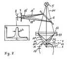
- the Fig. 8shows a schematic representation of the chromatic confocal measurement method.
- the light source 5produces a polychromatic illumination beam 14 which has a daylight-like spectrum and thus comprises short wavelength blue light, middle wavelength green light, and long wavelength red light.
- the illumination beam 14passes through the beam splitter 6 and is focused by the objective 12.
- the refraction angleis dependent on the wavelength of the refracted light so that the green colored medium wavelength region 14 'of the illumination beam 14 is focused on the measurement object surface 16 of the measurement object 17, the short wavelength blue spectral region 14 "of FIG Focusing the illumination beam 14 onto a focus point 20 above the measurement object surface 16 and focusing the short wavelength red region 14 '"onto the focus point 21 below the measurement object surface 16.
- the illumination beam 14is reflected back from the measurement object surface 16 as the observation beam 18 and redirected by the beam splitter 6 in the direction of the color sensor 8
- the aperture 7is arranged confocally to the focal point 19 on the measuring object surface 16, the beam splitter 6 and the color sensor 8. Consequently, only the green spectral range 18 "of medium wavelength passes through the aperture 7, the blue spectral range 18" and the red spectral range 18 '"d of observation beam 18 are filtered out.
- the image data of the color sensor 8are analyzed in their spectrum and the wavelength ⁇ i of the green spectral range 18 'is determined. From this wavelength ⁇ i, the absolute position of the measurement object surface 16 in the direction of the illumination beam 14 is then determined.
- the measuring range ⁇ Z of the illustrated deviceis located between the focal points 20 and 21 of the illumination beams 14 "and 14 '" outer spectral ranges, within which the absolute position of the measuring object surface 16 can be determined.
- the measurement range ⁇ Zthus increases with the spectrum width of the illumination beam 14.
- the advantage of the chromatic confocal measurement method over the monochromatic confocal measurement methodis that the focal length of the objective 12 need not be changed to move the focal point along the beam direction. Between the lens 12 and the object 12, the chromatic lens 33 is arranged in the beam path of the illumination beam 14 to bring the focus points 20 and 21 apart on the measuring range .DELTA.Z.
- the measuring range ⁇ Zis 30 mm.
Landscapes
- Physics & Mathematics (AREA)
- Spectroscopy & Molecular Physics (AREA)
- General Physics & Mathematics (AREA)
- Health & Medical Sciences (AREA)
- Chemical & Material Sciences (AREA)
- Analytical Chemistry (AREA)
- Optics & Photonics (AREA)
- General Health & Medical Sciences (AREA)
- Life Sciences & Earth Sciences (AREA)
- Biochemistry (AREA)
- Animal Behavior & Ethology (AREA)
- Radiology & Medical Imaging (AREA)
- Ophthalmology & Optometry (AREA)
- Immunology (AREA)
- Pathology (AREA)
- Oral & Maxillofacial Surgery (AREA)
- Dentistry (AREA)
- Epidemiology (AREA)
- Surgery (AREA)
- Public Health (AREA)
- Veterinary Medicine (AREA)
- Length Measuring Devices By Optical Means (AREA)
- Dental Tools And Instruments Or Auxiliary Dental Instruments (AREA)
- Spectrometry And Color Measurement (AREA)
- Measurement Of Optical Distance (AREA)
- Measuring And Recording Apparatus For Diagnosis (AREA)
Description
Translated fromGermanDie Erfindung betrifft eine Vorrichtung und ein Verfahren zur optischen 3D-Vermessung und zur Farbmessung.The invention relates to a device and a method for optical 3D measurement and color measurement.
Aus dem Stand der Technik sind mehrere Vorrichtungen zur optischen 3D-Vermessung bekannt. Die Vorrichtungen basieren oft auf optischen Messmethoden, wie der chromatischen konfokalen Messmethode oder der Triangulation- Messmethode.Several devices for 3D optical measurement are known from the prior art. The devices are often based on optical measurement methods, such as the chromatic confocal measurement method or the triangulation measurement method.
Der Artikel "
Darüber hinaus sind weitere Vorrichtungen zur Farbmessung aus dem Stand der Technik bekannt. Bei der Farbmessung wird das Messobjekt mit einem in seinem Spektrum tageslichtähnlichem Lichtstrahl bestrahlt und der zurückgestrahlte Lichtstrahl mittels eines Farbsensors, wie einer CCD- Kamera oder eines Spektrometers, aufgenommen und auf sein Spektrum hin analysiert. Aus diesem Spektrum kann dann der Farbton des Messobjekts bestimmt werden. In der Zahnmedizin wird die Farbmessung verwendet, um Zahnersatzteile farblich an natürliche Nachbarzähne anzupassen. Ein Nachteil solcher Vorrichtungen ist, dass sie entweder nur zur 3D-Vermessung oder nur zur Farbmessung geeignet sind. Insbesondere in der Zahnmedizin sind sowohl die Informationen aus der 3D-Vermessung als auch aus der Farbmessung zur Planung eines Zahnersatzteils erforderlich. Deshalb werden diese Informationen aufwendig unabhängig voneinander einerseits mittels bekannter 3D-Vemessungsvorrichtungen und andererseits mittels bekannter Farbmessungsvorrichtungen gewonnen.In addition, other devices for color measurement are known from the prior art. In colorimetry, the measurement object is irradiated with a daylight-like light beam in its spectrum, and the reflected light beam is recorded by means of a color sensor, such as a CCD camera or a spectrometer, and analyzed for its spectrum. From this spectrum then the hue of the DUT can be determined. In dentistry, the color measurement is used to color tooth replacement parts to match natural adjacent teeth. A disadvantage of such devices is that they are either only for 3D measurement or only suitable for colorimetry. Especially in dentistry, both the information from the 3D measurement and from the color measurement for planning a dental prosthesis part are required. Therefore, this information is consuming independently obtained on the one hand by means of known 3D-Vemessungsvorrichtungen and on the other hand by means of known color measuring devices.
Die Aufgabe dieser Erfindung besteht demnach darin, eine Vorrichtung bereitzustellen, die auf eine einfache Art und Weise sowohl eine 3D-Vermessung als auch eine Farbmessung eines Messobjekts ermöglicht.The object of this invention is therefore to provide a device which allows in a simple manner both a 3D measurement and a color measurement of a measurement object.
Diese Aufgabe wird durch die vorliegende Erfindung gelöst. Eine Ausführung der Erfindung umfasst eine Vorrichtung zur optischen 3D-Vermessung ein Objektiv, wobei die Vorrichtung zwischen einem ersten Modus für die optische 3D-Vermessung mittels der chromatischen konfokalen Messmethode und einem zweiten Modus für die Farbmessung verstellbar ist, indem mittels des Objektivs im ersten Modus ein breitbandiger Beleuchtungsstrahl auf eine erste Ebene einer Messobjektsoberfläche fokussierbar ist und im zweiten Modus der breitbandige Beleuchtungsstrahl mittels des Objektivs auf eine zweite Ebene außerhalb der ersten Ebene in einem Abstand d von der Messobjektsoberfläche fokussierbar ist.This object is achieved by the present invention. An embodiment of the invention comprises a device for optical 3D measurement of an objective, the device being adjustable between a first mode for 3D optical measurement by means of the chromatic confocal measuring method and a second mode for colorimetry, by means of the objective in the first mode a broadband illumination beam can be focused onto a first plane of a measurement object surface, and in the second mode the broadband illumination beam can be focused by the objective onto a second plane outside the first plane at a distance d from the measurement object surface.
Bei der 3D-Vermessung können die Oberflächeninformationen eines Messobjekts unter Verwendung unterschiedlicher Messmethoden, wie der chromatischen konfokalen Messmethode oder der Triangulation- Messmethode, erfasst werden. Ein breitbandiger Beleuchtungsstrahl wird dabei auf das Messobjekt gelenkt und das zurückgestrahlte Licht in Form eines Beobachtungsstrahls wird anschließend analysiert.In the 3D survey, the surface information of a measurement object can be detected using different measurement methods such as the chromatic confocal measurement method or the triangulation measurement method. A broadband illumination beam is thereby directed onto the measurement object and the reflected-back light in the form of an observation beam is subsequently analyzed.
Bei der chromatisch konfokalen Meßmethode wird ein polychromatischer Beleuchtungsstrahl auf die Oberfläche eines Messobjekt fokussiert. Der Brechungswinkel bei Lichtbrechung ist abhängig von der Wellenlänge des gebrochenen Lichts, so dass kurzwelliges Licht auf einen zum Objektiv näheren Fokuspunkt und langwelliges Licht auf einem vom Objektiv fernen Fokuspunkt fokussiert wird. Ein schmaler Spektralbereich des Beleuchtungsstrahls wird genau auf die erste Ebene der Messobjektsoberfläche fokussiert, wobei die übrigen Spektralbereiche nur unscharf auf dem Messobjekt abgebildet werden und Unschärfekreise bilden. Der zurückgestrahlte Beleuchtungsstrahl bildet einen Beobachtungsstrahl, der von einem Strahlteiler in Richtung des Farbsensors umgelenkt wird. Eine zwischen dem Strahlteiler und dem Farbsensor konfokal angeordneten Blende führt dazu, dass der auf das Messobjekt fokussierte Spektralbereich des Beobachtungsstrahls die Blende durchstrahlt, wobei die übrigen auf der Messobjektsoberfläche unscharf abgebildeten Spektralbereiche herausgefiltert werden. Die Wellenlänge des fokussierten Spektralbereichs kann mittels einer Spektralanalyse bestimmt werden und daraus die absolute Position des Messobjekts in Richtung des Beleuchtungsstrahls abgeleitet werden.In the chromatic confocal measurement method, a polychromatic illumination beam is focused on the surface of a measurement object. The refraction angle at refraction is dependent on the wavelength of the refracted light, so that short-wave light to a nearer to the lens focus point and long-wavelength light on one of the lens focused on the distant focus. A narrow spectral range of the illumination beam is focused precisely on the first plane of the measurement object surface, the remaining spectral ranges being imaged only blurred on the measurement object and forming blur circles. The reflected beam of illumination forms an observation beam, which is deflected by a beam splitter in the direction of the color sensor. An aperture arranged confocally between the beam splitter and the color sensor causes the spectral range of the observation beam focused on the measurement object to penetrate the diaphragm, the remaining spectral ranges imaged on the measurement object surface being filtered out. The wavelength of the focused spectral range can be determined by means of a spectral analysis and from this the absolute position of the measurement object in the direction of the illumination beam can be derived.
Bei einer nicht beanspruchten Triangulation- Messmethode wird der Beleuchtungsstrahl auf das Messobjekt projiziert. Der zurückgestrahlte Beobachtungsstrahl wird dann mittels eines Bildsensors, wie beispielsweise einer CCD- Kamera, detektiert. Aus der Lage und Richtung des Beleuchtungsstrahls und des Beobachtungsstrahls kann unter Verwendung trigonometrischer Rechenmethoden der Abstand zum Messobjekt bestimmt werden. Bei dieser Messmethode wird der Beobachtungsstrahl ungefiltert vom Farbsensor detektiert, so dass keine konfokal angeordnete Blende verwendet wird.In an unclaimed triangulation measurement method, the illumination beam is projected onto the measurement object. The reflected observation beam is then detected by means of an image sensor, such as a CCD camera. From the position and direction of the illumination beam and the observation beam, the distance to the measurement object can be determined using trigonometric calculation methods. In this measurement method, the observation beam is detected unfiltered by the color sensor, so that no confocal arranged aperture is used.
Die Weißlichtinterferometrie- Messmethode nutzt die Interferenz eines breitbandigen Lichts, wie beispielsweise des Weißlicht. Diese ebenfalls nicht beanspruchte Messmethode vergleicht die Laufzeit des vom Messobjekt zurückgestrahlten Beobachtungsstrahls mittels eines Interferometers, beispielsweise eines Michelson-Interferometers, mit der Laufzeit des Beleuchtungsstrahls mit bekannter optischer Weglänge als Referenz. Die Interferenz der beiden Lichtstrahlen ergibt ein Muster, aus dem man die relative optische Weglänge abgeleitet werden kann.The white light interferometry measurement method uses the interference of a broadband light, such as the white light. This measurement method, which is likewise not claimed, compares the transit time of the observation beam returned by the measurement object by means of an interferometer, for example a Michelson interferometer. with the duration of the illumination beam with known optical path length as a reference. The interference of the two light beams gives a pattern from which one can derive the relative optical path length.
Bei einer ebenfalls nicht beanspruchten Deflektometrie- Messmethode beobachtet man das Bild eines Lichtmusters, wie beispielsweise eines Gitters, in Reflexion über die Oberfläche des Messobjekts. Aus der Deformation des Gitterbildes kann man den lokalen Gradienten der Oberfläche bestimmen und daraus die 3D-Informationen des Messobjekts erzeugen. Dabei kann auch ein breitbandiger Lichtstrahl verwendet werden.In a likewise unclaimed deflectometry measurement method, the image of a light pattern, such as a grating, is observed in reflection over the surface of the measurement object. From the deformation of the lattice image, one can determine the local gradient of the surface and generate therefrom the 3D information of the measurement object. In this case, a broadband light beam can be used.
Bei den genannten optischen Messmethoden zur 3D-Vermessung tastet der breitbandige Beobachtungsstrahl innerhalb einer Messfläche das Messobjekt ab, um die Oberflächeninformationen dieser Messfläche zu erzeugen. Der breitbandige Beleuchtungsstrahl weist ein Spektrum auf, das vorteilhafterweise den sichtbaren Spektralbereich zwischen 400 nm und 800 nm umfasst. Der Beleuchtungsstrahl kann dabei ein oder mehrere punktförmige Lichtstrahlen, ein oder mehrere Lichtstreifen oder ein sonstiges Lichtmuster darstellen.In the case of the aforementioned optical measurement methods for 3D measurement, the broadband observation beam scans the measurement object within a measurement surface in order to generate the surface information of this measurement surface. The broadband illumination beam has a spectrum which advantageously comprises the visible spectral range between 400 nm and 800 nm. The illumination beam may represent one or more punctiform light rays, one or more light stripes or another light pattern.
Bei Messmethoden zur Farbmessung wird oft ein polychromatischer Beleuchtungsstrahl auf das Messobjekt umgeleitet dessen Spektrum dem Tageslichtspektrum ähnlich ist und der eine Farbtemperatur zwischen 5000 K und 6000 K aufweist. Der zurückgestrahlte Beobachtungsstrahl wird anschließend mittels eines Farbsensors, wie einer CCD- Kamera oder eines Spektrometers, auf seinen Spektralverlauf hin analysiert. Anhand des aufgenommenen Spektrums kann dann auf den Farbeindruck für ein menschliches Auge geschlossen werden und dem Messobjekt ein Farbton zugeordnet werden.In measurement methods for color measurement, a polychromatic illumination beam is often redirected to the measurement object whose spectrum is similar to the daylight spectrum and which has a color temperature between 5000 K and 6000 K. The reflected-back observation beam is then analyzed for its spectral response by means of a color sensor, such as a CCD camera or a spectrometer. Based on the recorded spectrum can then be closed to the color impression for a human eye and the measurement object to be assigned a hue.
Im ersten Modus wird der Beleuchtungsstrahl so fokussiert, dass zumindest das Licht einer Wellenlänge des polychromatischen Beleuchtungsstrahls seinen Fokuspunkt in der ersten Ebene der Messobjektsoberfläche hat und somit die Messobjektsoberfläche für diese Wellenlänge scharf auf dem Farbsensor abgebildet wird. Die Fokuspunkte für die übrigen Wellenlängen des polychromatischen Beleuchtungsstrahls liegen entweder oberhalb oder unterhalb der ersten Ebene der Messobjekts Oberfläche, so dass das Lichte dieser Wellenlängen unscharf auf dem Farbsensor abgebildet wird. Im zweiten Modus wird der Beleuchtungsstrahl auf eine zweite Ebene außerhalb der ersten Ebene der Messobjektsoberfläche fokussiert und bildet somit die Oberfläche unscharf ab. Der breitbandige Beleuchtungsstrahl wird demnach nicht auf einen Punkt, sondern auf einen ausgedehnten Unschärfekreis mit einem Durchmesser gebündelt und zwar sowohl für den Fall, dass der Fokuspunkt sich vor der ersten Ebene der Messobjektsoberfläche, als auch für den Fall, dass der Fokuspunkt sich hinter der ersten Ebene der Messobjektsoberfläche befindet. Der Beleuchtungsstrahl wird von der Messobjektsoberfläche innerhalb des Unschärfekreises als Beobachtungsstrahl zurückgestrahlt und kann zur Farbbestimmung verwendet werden.In the first mode, the illumination beam is focused so that at least the light is one wavelength of the polychromatic Illuminating beam has its focal point in the first plane of the measurement object surface and thus the measurement object surface for this wavelength is sharply imaged on the color sensor. The focus points for the remaining wavelengths of the polychromatic illumination beam are either above or below the first plane of the measurement object surface, so that the light of these wavelengths is imaged blurred on the color sensor. In the second mode, the illumination beam is focused on a second plane outside the first plane of the measurement object surface and thus forms the surface out of focus. The broadband illumination beam is therefore focused not on a point, but on an extended circle of blur with a diameter both in the case that the focus point in front of the first plane of the measurement object surface, as well as in the case that the focal point is behind the first Plane of the measurement object surface is located. The illumination beam is reflected back from the measurement object surface within the circle of blur as an observation beam and can be used for color determination.
Die Brennweite des Objektivs wird im ersten Modus so eingestellt, dass der Fokuspunkt für eine Wellenlänge in der ersten Ebene der Messobjektsoberfläche liegt. Im zweiten Modus wird die Brennweite so eingestellt, dass der Fokuspunkt für alle Wellenlängen außerhalb der ersten Ebene der Messobjektsoberfläche liegt. Zur Umschaltung zwischen dem ersten und dem zweiten Modus muss das optische System folglich nicht ausgetauscht werden, sondern lediglich in seiner Brennweite verstellt werden. Die Verstellung der Brennweite erfolgt durch ein Verdrehen eines Verstellmittels des Objektivs, das eine innere Mechanik des Objektivs verstellt, um die Brennweite zu ändern. Die Verstellung kann motorgesteuert oder auch manuell durch einen Benutzer erfolgen. Bei der chromatisch konfokalen Messmethode wird eine konfokale Blende vor dem Farbsensor angebracht, um ausschließlich das Licht des auf die Messobjektsoberfläche fokussierten Spektralbereichs durchzulassen. Falls im ersten Modus diese Messmethode verwendet wird, wird beim Umschalten aus dem ersten Modus in den zweiten Modus die Blende aus dem Strahlengang des Beobachtungsstrahls geschwenkt, um den Beobachtungsstrahl vollständig spektral analysieren zu können.The focal length of the lens is set in the first mode so that the focal point for one wavelength lies in the first plane of the measurement object surface. In the second mode, the focal length is set so that the focal point for all wavelengths is outside the first plane of the target surface. To switch between the first and the second mode, therefore, the optical system does not need to be replaced, but only be adjusted in its focal length. The adjustment of the focal length is effected by a rotation of an adjusting means of the lens, the internal mechanism of the lens adjusted to change the focal length. The adjustment can be motor-controlled or manually by a user. In the chromatic confocal measurement method, a confocal aperture is placed in front of the color sensor to pass only the light of the spectral range focused on the measurement object surface. If this measurement method is used in the first mode, when switching from the first mode to the second mode, the diaphragm is pivoted out of the beam path of the observation beam in order to be able to analyze the observation beam completely spectrally.
Ein Vorteil ist, dass sowohl die 3D-Vermessung als auch die Farbmessung mit der erfinderischen Vorrichtung durchgeführt werden kann. Dabei wird für beide Modi die selbe Lichtquelle und der selbe Farbsensor verwendet, die einen breitbandigen Beleuchtungsstrahl aussendet. Insbesondere in der Zahnmedizin wird somit die 3D-Vermessung und die Farbmessung von Zähnen im Rahmen einer Planung von Zahnersatz mit einer einzigen Vorrichtung ermöglicht.One advantage is that both the 3D measurement and the color measurement can be performed with the inventive device. In this case, the same light source and the same color sensor is used for both modes, which emits a broadband illumination beam. Thus, in particular in dentistry, the 3D measurement and the color measurement of teeth is made possible within the framework of planning dentures with a single device.
Ein weiterer Vorteil ist, dass die Kostenbelastung und der Platzbedarf durch Vereinigung einer Vorrichtung zur Farbmessung und einer Vorrichtung zur 3D-Vermessung in der erfinderischen Vorrichtung mit beiden Modi verringert wird.A further advantage is that the cost burden and the space requirement are reduced by combining a device for colorimetry and a device for 3D measurement in the inventive device with both modes.
Vorteilhafterweise kann eine Blende im ersten Modus bei Verwendung der chromatischen konfokalen Messmethode konfokal zur Messobjektsoberfläche in den Strahlengang eines Beobachtungsstrahls hineinschwenkbar sein und im zweiten Modus aus dem Strahlengang des Beobachtungsstrahls herausschwenkbar sein.Advantageously, a diaphragm in the first mode when using the chromatic confocal measurement method can confokal hineinschwenkbar to the object surface in the beam path of an observation beam and be swung out in the second mode of the beam path of the observation beam.
Die Blende kann um eine Achse drehbar gelagert sein, um seitlich zum Strahlengang geschwenkt zu werden. Im ersten Modus bei Verwendung der chromatischen konfokalen Messmethode wird die Blende konfokal angeordnet, um die auf der Messobjektsoberfläche unscharf abgebildeten Spektralbereiche herauszufiltern. Bei de nicht beanspruchten Triangulation- Messmethode wird keine konfokal angeordnete Blende verwendet. Im zweiten Modus zur Farbmessung wird die Blende aus dem Strahlengang herausgeschwenkt, um das volle Spektrum des Beobachtungsstrahls mittels des Farbsensors aufzunehmen.The aperture can be rotatably mounted about an axis to be pivoted laterally to the beam path. In the first mode when using the chromatic confocal measurement method the aperture is confocally arranged to filter out the spectral regions imaged on the object surface. The unclaimed triangulation measurement method does not use a confocal aperture. In the second mode for color measurement, the diaphragm is swiveled out of the beam path in order to record the full spectrum of the observation beam by means of the color sensor.
Vorteilhafterweise kann der Beleuchtungsstrahl zumindest innerhalb des sichtbaren Spektralbereichs zwischen 400 nm und 700 nm ein Spektrum aufweisen, das dem Tageslichtspektrum ähnlich ist.Advantageously, the illumination beam, at least within the visible spectral range between 400 nm and 700 nm, can have a spectrum which is similar to the daylight spectrum.
Ein solcher Beleuchtungsstrahl weist folglich den optischen Eindruck vom Tageslicht auf.Such an illumination beam thus has the visual impression of daylight.
Dadurch wird die Farbmessung im zweiten Modus mit einem Beleuchtungsstrahl durchgeführt, der die Beleuchtung des Messobjekts bei Tageslicht simuliert. Bei der Farbmessung wird also dar vom Messobjekt zurückgestrahlte Beobachtungsstrahl analysiert und dessen Farbton bestimmt, der einem optischen Eindruck des Messobjekts bei Tageslicht entspricht. Im ersten Modus zur 3D-Vermessung und im zweiten Modus kann die selbe Lichtquelle mit tageslichtähnlichem Spektrum bei einer Farbtemperatur zwischen 5000 und 6000 K verwendet werden.As a result, the color measurement in the second mode is carried out with an illumination beam which simulates the illumination of the measurement object in daylight. In the color measurement, therefore, the observation beam reflected back from the measurement object is analyzed and its hue determined, which corresponds to an optical impression of the measurement object in daylight. In the first mode for 3D measurement and in the second mode, the same light source with daylight-like spectrum at a color temperature between 5000 and 6000 K can be used.
Vorteilhafterweise kann mittels einer umschaltbaren Lichtquelle im ersten Modus ein Beleuchtungsstrahl mit einem breitbandigen Spektrum und im zweiten Modus ein Beleuchtungsstrahl mit einem tageslichtähnlichem Spektrum erzeugbar sein.Advantageously, by means of a switchable light source in the first mode, an illumination beam with a broadband spectrum and in the second mode an illumination beam with a spectrum similar to daylight can be generated.
Bei einer umschaltbaren Lichtquelle kann im ersten Modus eine weiße Lichtquelle mit einem breiten Spektrum und im zweiten Modus eine andere Lichtquelle mit einem tageslichtähnlichem Spektrum verwendet werden. Beim Umschalten zwischen den beiden Modi wird entweder die Lichtquelle ausgetauscht oder das Spektrum der Lichtquelle wird entsprechend verändert. Beispielsweise können mehrere farbige LED's so angesteuert werden, dass durch Überlagerung ihrer Spektren entweder ein tageslichtähnliches Spektrum oder ein breitbandiges weißes Spektrum erzeugt wird. Für die Wirkungsweise der chromatisch konfokalen Messmethode ist der Intensitätsverlauf des breitbandigen Spektrums in Abhängigkeit von der Wellenlänge unwesentlich, so dass das breitbandige Spektrum mehrere Maxima und Minima bei verschiedenen Wellenlängen aufweisen kann.In the case of a switchable light source, in the first mode a white light source with a wide spectrum and in the second mode another light source with a daylight-like light source can be used Spectrum can be used. When switching between the two modes, either the light source is replaced or the spectrum of the light source is changed accordingly. For example, a plurality of colored LEDs can be controlled in such a way that either a daylight-like spectrum or a broadband white spectrum is generated by superimposing their spectra. For the mode of operation of the chromatic confocal measuring method, the intensity profile of the broadband spectrum as a function of the wavelength is insignificant, so that the broadband spectrum can have several maxima and minima at different wavelengths.
Bei einer weiteren Ausführung der Erfindung ist mittels eines Schwenkmechanismus ein erstes Objektiv zum Betreiben im ersten Modus und ein zweites Objektiv zum Betreiben im zweiten Modus in den Strahlengang des Beleuchtungsstrahls schwenkbar.In a further embodiment of the invention, a first objective for operating in the first mode and a second objective for operating in the second mode are pivotable into the beam path of the illumination beam by means of a pivoting mechanism.
Die Brennweite des ersten Objektivs ist so bemessen, dass der Beleuchtungsstrahl auf die erste Ebene der Messobjektsoberfläche fokussiert wird und die Brennweite des zweiten Objektivs ist so bemessen, dass der Beleuchtungsstrahl auf eine zweite Ebene außerhalb der ersten Ebene der Messobjektsoberfläche fokussiert wird. Beim Umschalten zwischen den beiden Modi wird das entsprechende Objektiv mittels eines Schwenkmechanismus in den Strahlengang des Beleuchtungsstrahls geschwenkt. Dadurch bleibt der übrige optische Aufbau der Vorrichtung unverändert und der Schwenkmechanismus kann beispielsweise mittels eines Auslösers, wie eines Drehknopfes oder Steuerhebels zwischen den beiden Modi verstellt werden. Die Verstellung kann motorgesteuert oder manuell durch den Benutzer erfolgen.The focal length of the first lens is sized to focus the illumination beam onto the first plane of the measurement object surface, and the focal length of the second objective is sized to focus the illumination beam to a second plane outside the first plane of the measurement object surface. When switching between the two modes, the corresponding lens is pivoted by means of a pivoting mechanism in the beam path of the illumination beam. As a result, the remaining optical structure of the device remains unchanged and the pivot mechanism can be adjusted, for example by means of a trigger, such as a knob or control lever between the two modes. The adjustment can be motor-controlled or manually by the user.
Bei einer weiteren Ausführung der Erfindung ist zum Betreiben im ersten Modus ein erste Objektiv und zum Betreiben im zweiten Modus ein zweites Objektiv durch einen Benutzer in den Strahlengang des Beleuchtungsstrahls einbringbar.In a further embodiment of the invention for operating in the first mode, a first lens and for operating in the second mode, a second Objectively introduced by a user in the beam path of the illumination beam.
In der Vorrichtung können Befestigungsmittel, wie beispielsweise flexible Spannklammern, angebracht sein, die ein genaues Positionieren des Objektivs im Strahlengang des Beleuchtungsstrahls ermöglichen. Dadurch kann der Benutzer durch das Austauschen der Objektive den Modus der Vorrichtung wechseln. Ein Vorteil ist, dass im Gehäuse der Vorrichtung in jedem der beiden Modi jeweils nur ein Objektiv mit starrer Brennweite Raum finden muss, so dass die Vorrichtung kleiner in ihren Ausmaßen konstruiert werden kann.In the device fastening means, such as flexible clamps, be attached, which allow a precise positioning of the lens in the beam path of the illumination beam. This allows the user to change the mode of the device by replacing the lenses. One advantage is that in each case only one objective with a fixed focal length has to be accommodated in the housing of the device in each of the two modes, so that the device can be designed to be smaller in size.
In einer weiteren Ausführung besteht die Vorrichtung aus einer Basiseinheit und einem Handstück, die miteinander über einen Lichtleiter verbunden sind, wobei die Basiseinheit eine Lichtquelle, einen Strahlteiler und einen Farbsensor umfasst und das Handstück das Objektiv umfasst.In a further embodiment, the device consists of a base unit and a handpiece, which are connected to each other via a light guide, wherein the base unit comprises a light source, a beam splitter and a color sensor and the handpiece comprises the lens.
Die Basiseinheit der Vorrichtung ist ein festinstallierter Aufbau. Die Lichtquelle in der Basiseinheit strahlt einen Beleuchtungsstrahl mit polychromatischem Spektrum aus, das dem Spektrum von Tageslicht entspricht oder möglichst ähnlich ist. Der Beleuchtungsstrahl passiert des Strahlteiler und wird über den Lichtleiter an das Handstück geleitet. Im Handstück wird der Beleuchtungsstrahl mittels des Objektivs im ersten Modus auf die erste Ebene der Messobjektsoberfläche und im zweiten Modus auf eine zweite Ebene außerhalb der ersten Ebene der Messobjektsoberfläche fokussiert. Der vom Messobjekt zurückgestrahlte Beobachtungsstrahl gelangt über den Lichtleiter zurück in der Basiseinheit und wird mittels des Strahlteilers zum Farbsensor umgelenkt. Die Bilddaten des Farbsensors können dann zur Bildanalyse an eine Bildanalyseeinheit über ein Datenkabel oder der Funk übermittelt werden.The base unit of the device is a fixed installation. The light source in the base unit emits an illumination beam with polychromatic spectrum, which corresponds to the spectrum of daylight or is as similar as possible. The illumination beam passes through the beam splitter and is guided via the light guide to the handpiece. In the handpiece, the illumination beam is focused by means of the objective in the first mode on the first plane of the measurement object surface and in the second mode on a second plane outside the first plane of the measurement object surface. The observation beam reflected back from the measurement object passes back into the base unit via the light guide and is deflected by means of the beam splitter to the color sensor. The image data of the color sensor can then be transmitted for image analysis to an image analysis unit via a data cable or the radio.
Dadurch kann das Handstück unabhängig von der Basiseinheit bewegt werden und verbessert somit den Bedienkomfort. Darüber hinaus kann das Handstück in seinen Ausmaßen schmal konstruiert werden, da es nur das Objektiv und eventuell Umlenkspiegel enthält und die übrigen optischen Bauteile wie Lichtquelle, Strahlteiler und Farbsensor in der Basiseinheit eingebaut sind. Insbesondere bei der Anwendung der Vorrichtung zu zahnmedizinischen Zwecken wird dadurch der Zugang zu Messobjekten wie Zähnen in der Mundhöhle eines Patienten erleichtert.As a result, the handpiece can be moved independently of the base unit and thus improves the ease of use. In addition, the handpiece can be designed narrow in its dimensions, since it contains only the lens and possibly deflecting mirror and the other optical components such as light source, beam splitter and color sensor are installed in the base unit. In particular, in the application of the device for dental purposes, thereby access to objects such as teeth in the oral cavity of a patient is facilitated.
Zum Betreiben im ersten Modus ist das erste Handstück mit dem ersten Objektiv und zum Betreiben im zweiten Modus ein zweites Handstück mit dem zweiten Objektiv durch einen Benutzer mit der Basiseinheit verbindbar.For operation in the first mode, the first handpiece with the first lens and for operation in the second mode, a second handpiece with the second lens is connectable by a user with the base unit.
Durch den Austausch der Handstücke wechselt somit der Modus der Vorrichtung. Im zweiten Modus bleibt der Beleuchtungsstrahl in seiner Ausrichtung relativ zum Handstück unverändert, wobei im ersten Modus der Beleuchtungsstrahl eine oszillierende Abtastbewegung zur optischen Abtastung eines Messfeldes vollführt. Diese Abtastbewegung kann beispielsweise durch einen Drehspiegel erzeugt werden, der entsprechend geschwenkt wird. Das zweite Handstück kann kompakter als das erste Handstück konstruiert werden, da im ersten Modus kein Mechanismus, wie ein Drehspiegel, zur Erzeugung einer Abtastbewegung erforderlich ist.The replacement of the handpieces thus changes the mode of the device. In the second mode, the illumination beam remains unchanged in its orientation relative to the handpiece, wherein in the first mode the illumination beam performs an oscillating scanning movement for the optical scanning of a measuring field. This scanning movement can be generated for example by a rotating mirror, which is pivoted accordingly. The second handpiece can be constructed to be more compact than the first handpiece because in the first mode no mechanism, such as a rotating mirror, is required to generate a scanning movement.
Vorteilhafterweise kann die einteilige Vorrichtung, umfassend eine Lichtquelle, einen Strahlteiler, einen Farbsensor, ein Objektiv, mit einem Gehäuse verkleidet sein.Advantageously, the one-piece device comprising a light source, a beam splitter, a color sensor, a lens, be covered with a housing.
Die Vorrichtung kann einteilig konstruiert werden, indem alle Bauteile in einem Gehäuse angebracht werden. Ein Datenkabel verbindet dann die Vorrichtung mit einer Bildanalyseeinheit, um die Daten des Farbsensors zu analysieren. Im Vergleich mit der zweiteiligen Ausführungsform aus dem Handstück und der Basiseinheit wird der flexible Leichtleiter eingespart.The device can be constructed in one piece by mounting all components in a housing. A data cable then connects the device to an image analysis unit, to analyze the data of the color sensor. Compared with the two-part embodiment of the handpiece and the base unit of the flexible light conductor is saved.
Im zweiten Modus ist zur Farbmessung die Brennweite des Objektivs so gewählt, dass der Beleuchtungsstrahl auf eine zweite Ebene außerhalb der ersten Ebene der Messobjektsoberfläche fokussiert wird und der Beleuchtungsstrahl als ein Messfeld in der Form eines Unschärfekreises mit homogener Intensität unscharf auf der Messobjektsoberfläche abgebildet wird.In the second mode, for colorimetry, the focal length of the objective is selected so that the illumination beam is focused on a second plane outside the first plane of the measurement object surface and the illumination beam is imaged as a measurement field in the form of a uniform intensity blur circle on the measurement object surface.
Dadurch wird ein Messfeld mit homogener Intensität und einem tageslichtähnlichem Spektrum bereitgestellt, das zur Farbmessung notwendig ist.As a result, a measurement field with homogeneous intensity and a daylight-like spectrum is provided, which is necessary for color measurement.
Vorteilhafterweise kann der Beleuchtungsstrahl aus mehreren Teilstrahlen bestehen, die in einer Ebene parallel zueinander verlaufen.Advantageously, the illumination beam may consist of a plurality of partial beams which extend in a plane parallel to each other.
Bei mehreren Teilstrahlen werden auch mehrere Objektive verwendet, um die Teilstrahlen in gewünschter Weise zu fokussieren.With multiple sub-beams, multiple lenses are used to focus the sub-beams in the desired manner.
Dadurch kann im ersten Modus die Zeitdauer der 3D-Vermessung erheblich verkürzt werden, da die Teilstrahlen parallel mit einer gleichzeitigen Abtastbewegung die Messobjektsoberfläche erfassen. Im zweiten Modus bilden die einzelnen Teilstrahlen mehrere Unschärfekreise auf der Messobjektsoberfläche ab, die sich zu einem streifenförmigen Messfeld überlagern. Dieses Messfeld weist einen tageslichtähnliches Spektrum und eine homogene Intensitätsverteilung auf, so dass dieses Messfeld zur Farbmessung geeignet ist.As a result, in the first mode, the duration of the 3D measurement can be considerably shortened, since the partial beams detect the object surface in parallel with a simultaneous scanning movement. In the second mode, the individual sub-beams form a plurality of blur circles on the measurement object surface, which overlap to form a strip-shaped measuring field. This measuring field has a daylight-like spectrum and a homogeneous intensity distribution, so that this measuring field is suitable for color measurement.
Vorteilhafterweise können mittels des Objektivs, umfassend mehrere Teilobjektive, die einzelnen Teilstrahlen im ersten Modus auf Fokuspunkte fokussiert werden, die in einer Reihe auf der ersten Ebene der Messobjektsoberfläche angeordnet sind. Im zweiten Modus können die einzelnen Teilstrahlen auf Fokuspunkte fokussiert werden, die in einer Reihe auf der zweiten Ebene außerhalb der ersten Ebene angeordnet sind, so dass die Teilstrahlen unscharf in Form von Unschärfekreisen auf der Messobjektsoberfläche abgebildet werden und sich zu einem Messfeld überlagern.Advantageously, by means of the objective, comprising a plurality of partial objectives, the individual partial beams in the first mode can be focused on focus points which are arranged in a row on the first plane of the object surface. In the second mode, the individual sub-beams can be focused on focus points, which are arranged in a row on the second plane outside the first plane, so that the sub-beams are blurred in the form of blur circles on the measurement object surface and overlap to form a measurement field.
Das erste Objektiv umfasst mehrere Teilobjektive für die einzelnen Teilstrahlen, deren Steuerung der Brennweite aneinander mittels eines Kopplungsmechanismus gekoppelt ist, so dass die Brennweite aller Teilobjektive synchron verstellt wird. Dadurch können die Fokuspunkte der einzelnen Teilstrahlen durch einen Benutzer in gewünschter Weise gleichzeitig verschoben werden.The first lens comprises a plurality of partial lenses for the individual partial beams whose control of the focal length is coupled to each other by means of a coupling mechanism, so that the focal length of all partial lenses is adjusted synchronously. As a result, the focus points of the individual partial beams can be moved simultaneously by a user in the desired manner.
Vorteilhafterweise kann die Vorrichtung einen Umlenkspiegel aufweisen, der den Beleuchtungsstrahl auf das Messobjekt umlenkt.Advantageously, the device may have a deflection mirror, which deflects the illumination beam onto the measurement object.
Der Beleuchtungsstrahl kann beispielsweise im rechten Winkel auf das Messobjekt umgelenkt werden. Dadurch wird insbesondere die Aufnahme von Zähnen in der Mundhöhle eines Patienten erleichtert.The illumination beam can, for example, be deflected at right angles to the measurement object. As a result, in particular the inclusion of teeth in the oral cavity of a patient is facilitated.
Vorteilhafterweise kann bei Verwendung einer chromatisch konfokalen Messmethode die Vorrichtung eine Blende zwischen dem Objektiv und dem Farbsensor aufweisen, um nur denjenigen Spektralbereich eines vom Objekts zurückgestrahlten Beobachtungsstrahls zum Farbsensor durchzulassen, der auf die erste Ebene der Messobjektsoberfläche fokussiert ist.Advantageously, when using a chromatic confocal measuring method, the device can have a diaphragm between the objective and the color sensor, in order to transmit only that spectral range of an observation beam reflected back from the object to the color sensor, which is focused on the first plane of the measurement object surface.
Die konfokal angeordnete Blende ist ein wesentliches Element der chromatisch konfokale Messmethode. Aus der Wellenlänge des herausgefilterten Spektralbereichs wird anschließend die absolute Position der Messobjektsoberfläche in der Richtung des Beleuchtungsstrahls bestimmt. Die übrigen beiden Koordinaten der Position in senkrechter Richtung zum Beleuchtungsstrahl werden aus den Bilddaten des Farbsensors bestimmt.The confocal aperture is an essential element of the chromatic confocal measurement method. The absolute position of the object surface in the direction of the illumination beam is then determined from the wavelength of the filtered-out spectral range. The other two coordinates of the position in the direction perpendicular to the illumination beam are determined from the image data of the color sensor.
Vorteilhafterweise kann der Durchmesser der Blende im ersten Modus zur 3D-Vermessung mittels der chromatischen konfokalen Messmethode größer als der Durchmesser der Blende im zweiten Modus zur Farbmessung sein, so dass die Tiefenschärfe im ersten Modus geringer als die Tiefenschärfe im zweiten Modus ist.Advantageously, in the first mode for 3D measurement by means of the chromatic confocal measuring method, the diameter of the diaphragm may be larger than the diameter of the diaphragm in the second mode for colorimetry, so that the depth of field in the first mode is less than the depth of field in the second mode.
Im ersten Modus ist der Durchmesser der Blende größer und die Tiefenschärfe somit geringen, so dass der Beobachtungsstrahl scharf auf dem Farbsensor abgebildet wird und mittels der chromatischen konfokalen Messmethode aus der scharf fokussierten Wellenlänge die Messtiefe berechnet werden kann. Im zweiten Modus ist der Durchmesser der Blende kleiner und die Tiefenschärfe somit größer, so dass alle Wellenlängen nahezu scharf abgebildet werden und sich zu einem weißen Lichtfeld überlagern, wobei keine der Wellenlängen dominiert. Dieses weiße Lichtfeld wird vom Farbsensor detektiert und die Bilddaten zur Farbmessung verwendet.In the first mode, the diameter of the aperture is larger and the depth of field is therefore small, so that the observation beam is imaged sharply on the color sensor and the measurement depth can be calculated by means of the chromatic confocal measuring method from the sharply focused wavelength. In the second mode, the diameter of the aperture is smaller and the depth of focus is thus larger, so that all wavelengths are almost sharply imaged and superimposed to form a white light field, with none of the wavelengths dominating. This white light field is detected by the color sensor and the image data is used for color measurement.
Vorteilhafterweise kann die Blende steuerbar sein und der Durchmesser der Blende verstellbar sein.Advantageously, the aperture can be controlled and the diameter of the aperture be adjustable.
Die Blende kann eine Irisblende sein, deren Durchmesser durch Verdrehen eines äußeren Rings der Irisblende verstellt werden kann.The iris can be an iris diaphragm whose diameter can be adjusted by turning an outer ring of the iris diaphragm.
Vorteilhafterweise kann die Blende mit einem größeren Durchmesser im ersten Modus gegen eine Blende mit einem kleineren Durchmesser im zweiten Modus ausgetauscht werden.Advantageously, the larger diameter aperture in the first mode can be replaced with a smaller diameter aperture in the second mode.
Die erste Blende mit einem größeren Durchmesser im ersten Modus kann unter Verwendung eines mechanischen mittels gegen die zweite Blende mit einem kleineren Durchmesser im zweiten Modus ausgetauscht werden.The first larger diameter orifice in the first mode may be exchanged using the mechanical means for the second smaller diameter orifice in the second mode.
Vorteilhafterweise kann die Tiefenschärfe der Vorrichtung im ersten Modus zwischen 0,1 mm und 1 mm betragen und die Tiefenschärfe der Vorrichtung im zweiten Modus zwischen 5 mm und 30 mm betragen.Advantageously, the depth of field of the device in the first mode can be between 0.1 mm and 1 mm, and the depth of focus of the device in the second mode can be between 5 mm and 30 mm.
Der Bereich der Tiefenschärfe im ersten Modus zwischen 0,1 mm und 1 mm ist besonders geeignet um die Koordinate der Messobjekts Oberfläche mittels der chromatischen konfokalen Messmethode festzustellen. Der Bereich der Tiefenschärfe im zweiten Modus zur Farbmessung zwischen 5 mm und 30 mm ist besonders vorteilhaft, da das auf das Objekt, beispielsweise einen Zahn von etwa 20 mm Höhe, projizierte Lichtfeld eine homogene intensiviert Verteilung und ein weißes, vorteilhafterweise tageslichtähnliches, Spektrum aufweisen muss. Außerhalb des Tiefenschärfebereichs dominieren diejenigen Wellenlängen, die scharf abgebildet werden.The range of depth of field in the first mode between 0.1 mm and 1 mm is particularly suitable for determining the coordinate of the object surface using the chromatic confocal measuring method. The range of depth of focus in the second mode for color measurement between 5 mm and 30 mm is particularly advantageous since the light field projected onto the object, for example a tooth of about 20 mm height, must have a homogeneous intensified distribution and a white, advantageously daylight-like, spectrum , Outside the depth-of-field, those wavelengths that are sharply focused dominate.
Vorteilhafterweise kann die Lichtquelle in ihrer Intensität so verstellbar sein, dass im zweiten Modus der Abfall der Lichtmenge durch einen kleineren Durchmesser der Blende mit einem Anstieg der Intensität der Lichtquelle kompensiert werden kann, um eine Farbmessung zu ermöglichen.Advantageously, the intensity of the light source can be adjustable so that in the second mode the drop in the amount of light due to a smaller diameter of the diaphragm can be compensated for by an increase in the intensity of the light source in order to enable colorimetry.
Für die Farbmessung ist eine bestimmte Intensität des detektierten Beobachtungsstrahls notwendig. Die Intensität der Lichtquelle wird erhöht, um die geringere Lichtmenge durch einen kleineren Durchmesser der Blende zu kompensieren und um die notwendige Intensität des Lichtfeldes zu erreichen.For the color measurement, a certain intensity of the detected observation beam is necessary. The intensity of the light source is increased to compensate for the smaller amount of light through a smaller diameter of the aperture and to achieve the necessary intensity of the light field.
Vorteilhafterweise kann zwischen dem Objektiv und dem Messobjekt ein chromatisches Objektiv angeordnet sein, wobei das chromatische Objektiv im ersten Modus für die optische 3D-Vermessung mittels der chromatischen konfokalen Messmethode in den Strahlengang des Beleuchtungsstrahls eingebracht ist und im zweiten Modus für die Farbmessung aus dem Strahlengang des Beleuchtungsstrahls herausgeschwenkt ist.Advantageously, a chromatic lens can be arranged between the objective and the measurement object, wherein the chromatic objective is introduced into the beam path of the illumination beam in the first mode for the optical 3D measurement by means of the chromatic confocal measurement method and in the second mode for the color measurement from the beam path of the illumination Illuminating beam is swung out.
Das chromatische Objektiv verstärkt den Effekt der chromatischen Abberationen, so dass die Fokuspunkte für die unterschiedlichen Wellenlängen deutlich auseinandergezogen werden. Dadurch dominiert im Beobachtungsstrahl 18 jeweils diejenige Wellenlänge, deren Fokuspunkt gerade auf der Messobjektsoberfläche 16 liegt. Die Fokuspunkte für eine Wellenlänge von 400 nm und eine Wellenlänge von 800 nm für ein tageslichtähnliches Spektrum können 30 mm auseinander liegen. Damit wird die Höhe eines Objekts, wie eines Zahns; abgedeckt. Im zweiten Modus wird das chromatische Objektiv um eine Schwenkachse aus dem Beleuchtungsstrahl herausgeschwenkt, so dass die Fokuspunkte der unterschiedlichen Wellenlängen zusammenrücken und sich nahezu überlagern. Die überlagerten Wellenlängen bilden somit ein homogenes weißes Lichtfeld mit einem tageslichtähnlichen Spektrum.The chromatic lens enhances the effect of chromatic aberrations so that the focus points for the different wavelengths are clearly separated. As a result, in the
Vorteilhafterweise kann das chromatische Objektiv Bestandteil des Objektivs sein.Advantageously, the chromatic lens may be part of the objective.
Das chromatische Objektiv kann zusammen mit dem Objektiv als eine gemeinsame optische Einheit in einem Gehäuse angeordnet sein.The chromatic lens may be disposed together with the lens as a common optical unit in a housing.
Vorteilhafterweise kann das chromatische Objektiv um eine Schwenkachse aus dem Strahlengang des Beobachtungsstrahls herausschwenkbar sein.Advantageously, the chromatic lens can be swiveled out of the beam path of the observation beam about a pivot axis.
Das chromatische Objektiv kann getrennt vom Objektiv um die Schwenkachse schwenkbar angeordnet sein. Die Schwenkbewegung kann mechanisch durch ein elektronisch angesteuertes Schwenkmittel erzeugt werden.The chromatic lens may be pivotally mounted separately from the lens about the pivot axis. The pivoting movement can be generated mechanically by an electronically controlled pivoting means.
Vorteilhafterweise kann die Vorrichtung schmal und bogenförmig geformt sein, um eine 3D-Vermessung von Zähnen innerhalb einer Mundhöhle eines Patienten und zur Farbmessung von Zahnoberflächen zu ermöglichen.Advantageously, the device may be narrow and arcuate in shape to permit 3D measurement of teeth within a patient's oral cavity and for color measurement of tooth surfaces.
Die erfinderische Vorrichtung kann insbesondere als zahnmedizinische Vorrichtung zur 3D-Vermessung und Farbmessung von Zähnen verwendet werden. Die Ergebnisse dieser Messungen, wie die 3D-Daten von Zahnoberflächen und vom Zahnfleisch und der Farbton der Zahnoberflächen, können anschließend zur Planung von Zahnersatzteilen verwendet werden.The inventive device can be used in particular as a dental device for 3D measurement and color measurement of teeth. The results of these measurements, such as the 3D data of tooth surfaces and gums and the color of the tooth surfaces, can then be used to design dental prostheses.
Ein weiterer Gegenstand der Erfindung ist ein Verfahren zur optischen 3D-Vermessung und zur Farbmessung, wobei eine Vorrichtung zwischen einem ersten Modus für die optische 3D-Vermessung mittels der chromatischen konfokalen Messmethode und einem zweiten Modus für die Farbmessung verstellt wird. Im ersten Modus wird ein breitbandiger Beleuchtungsstrahl auf eine erste Ebene einer Messobjektsoberfläche fokussiert und im zweiten Modus wird der breitbandige Beleuchtungsstrahl auf eine zweite Ebene außerhalb der ersten Ebene in einem Abstand d von der Messobjektsoberfläche fokussiert.Another object of the invention is a method for optical 3D measurement and color measurement, wherein a device between a first mode for 3D optical measurement by means of the chromatic confocal measurement method and a second mode for the color measurement is adjusted. In the first mode, a broadband illumination beam is focused on a first plane of a measurement object surface, and in the second mode, the broadband illumination beam is focused on a second plane outside the first plane at a distance d from the measurement object surface.
Im zweiten Modus wird der Beleuchtungsstrahl unscharf auf der Messobjektsoberfläche abgebildet, so dass ein Unschärfekreis erzeugt wird, der zur Farbmessung geeignet ist.In the second mode, the illumination beam is blurred on the measurement object surface, producing a blur circle suitable for colorimetry.
Als optisches System zur Fokussierung des Beleuchtungsstrahls kann ein Objektiv verwendet werden. Seine Brennweite wird so verstellt, dass der Beobachtungsstrahl im ersten Modus auf die erste Ebene in der Messobjektsoberfläche fokussiert wird und im zweiten Modus auf die zweite Ebene fokussiert wird.As an optical system for focusing the illumination beam, a lens can be used. Its focal length is adjusted so that the observation beam is focused in the first mode on the first level in the measurement object surface and in the second mode is focused on the second level.
Ein Vorteil des erfinderischen Verfahrens ist, dass der selbe Beleuchtungsstrahl für beide Modi verwendet wird und die Umschaltung zwischen den Modi durch Verstellung der Brennweite eines optischen Systems, wie beispielsweise eines Objektivs, bis zum Fokuspunkt erfolgt.An advantage of the inventive method is that the same illumination beam is used for both modes and the switching between the modes is done by adjusting the focal length of an optical system, such as a lens, to the focal point.
Vorteilhafterweise kann eine Blende im ersten Modus bei Verwendung der chromatischen konfokalen Messmethode konfokal zur Messeobjektsoberfläche in den Strahlengang eines Beobachtungsstrahls hineingeschwenkt werden und im zweiten Modus aus dem Strahlengang des Beobachtungsstrahls herausgeschwenkt werden.In the first mode, when the chromatic confocal measuring method is used, a diaphragm can advantageously be confocally pivoted into the beam path of an observation beam and, in the second mode, swung out of the beam path of the observation beam.
Im ersten Modus ist die konfokal angeordnete Blende ein notwendige Voraussetzung zur Verwendung der chromatisch konfokalen Messmethode. Im zweiten Modus wird die Blende herausgeschwenkt, da sie sonst den Beobachtungsstrahl unnötig einengen würde.In the first mode, the confocal aperture is a necessary condition for using the chromatic confocal measurement method. In the second mode, the aperture is swung out, otherwise it would unnecessarily constrict the observation beam.
Vorteilhafterweise kann mittels einer umschaltbaren Lichtquelle im ersten Modus ein Beleuchtungsstrahl mit einem breitbandigen Spektrum und im zweiten Modus ein Beleuchtungsstrahl mit einem tageslichtähnlichem Spektrum erzeugt werden.Advantageously, by means of a switchable light source in the first mode, an illumination beam with a broadband spectrum and in the second mode an illumination beam with a spectrum similar to daylight can be generated.
Dadurch kann beim Umschalten der Lichtquelle das Spektrum entsprechend dem jeweiligen Modus verändert werden. Das Spektrum zur 3D-Vermessung kann auch aus mehreren einzelnen Spektralbereichen mit verschiedenen Wellenlängen zwischen 400 nm und 700 nm bestehen.As a result, the spectrum can be changed according to the respective mode when switching the light source. The spectrum for 3D measurement can also consist of several individual spectral ranges with different wavelengths between 400 nm and 700 nm.
Vorteilhafterweise kann bei der Verstellung der Vorrichtung vom ersten Modus in den zweiten Modus mittels eines Schwenkmechanismus das erste Objektiv aus dem Strahlengang des Beleuchtungsstrahls herausgeschwenkt und ein zweites Objektiv in den Strahlengang des Beleuchtungsstrahls hineingeschwenkt werden.Advantageously, during the adjustment of the device from the first mode to the second mode by means of a pivoting mechanism, the first objective can be pivoted out of the beam path of the illumination beam and a second objective can be pivoted into the beam path of the illumination beam.
Dadurch erfolgt die Umschaltung vom ersten in den zweiten Modus durch Austausch des ersten Objektivs gegen das zweite Objektiv, wobei beide Objektive an einem Schwenkmechanismus innerhalb eines Gehäuses der Vorrichtung angebracht sind.Thereby, the switching from the first to the second mode is effected by replacing the first lens with the second lens, both lenses being mounted on a pivot mechanism within a housing of the apparatus.
Vorteilhafterweise kann bei der Verstellung der Vorrichtung vom zweiten Modus in den ersten Modus mittels des Schwenkmechanismus das zweite Objektiv aus dem Strahlengang des Beleuchtungsstrahls herausgeschwenkt und ein erste Objektiv in den Strahlengang des Beleuchtungsstrahls hineingeschwenkt wird.Advantageously, in the adjustment of the device from the second mode to the first mode by means of the pivoting mechanism, the second lens is pivoted out of the beam path of the illumination beam and a first lens is pivoted into the beam path of the illumination beam.
Dadurch erfolgt die Umschaltung vom zweiten in den ersten Modus durch Austausch des zweiten Objektivs gegen das erste Objektiv mittels des Schwenkmechanismus.As a result, the switchover from the second to the first mode takes place by replacing the second objective with the first objective by means of the pivoting mechanism.
Vorteilhafterweise kann bei der Verstellung der Vorrichtung vom ersten Modus in den zweiten Modus durch einen Benutzer das erste Objektiv aus dem Strahlengang des Beleuchtungsstrahls herausgenommen und ein zweites Objektiv in den Strahlengang des Beleuchtungsstrahls eingesetzt wird.Advantageously, during the adjustment of the device from the first mode to the second mode by a user, the first lens is taken out of the beam path of the illumination beam and a second lens is inserted into the beam path of the illumination beam.
Dadurch erfolgt die Umschaltung vom ersten in den zweiten Modus durch Austausch des ersten Objektivs gegen das zweite Objektiv manuell durch einen Benutzer. Zur präzisen Befestigung des Objektivs im Strahlengang ist eine Einspannvorrichtung, wie eine Einspannklammer, erforderlich.As a result, the changeover from the first to the second mode takes place by exchanging the first objective with the second one Lens manually by a user. For precise attachment of the lens in the beam path, a clamping device, such as a clamping bracket, is required.
Vorteilhafterweise kann bei der Verstellung der Vorrichtung vom zweiten Modus in den ersten Modus durch einen Benutzer das zweite Objektiv aus dem Strahlengang des Beleuchtungsstrahls herausgenommen und das erste Objektiv in den Strahlengang des Beleuchtungsstrahls eingesetzt wird.Advantageously, during the adjustment of the device from the second mode to the first mode by a user, the second lens is taken out of the beam path of the illumination beam and the first objective is inserted into the beam path of the illumination beam.
Dadurch erfolgt die Umschaltung vom zweiten in den ersten Modus durch Austausch des zweiten Objektivs gegen das erste Objektiv manuell durch einen Benutzer.As a result, switching from the second to the first mode is performed manually by a user by replacing the second lens with the first lens.
Falls die Vorrichtung aus einer Basiseinheit und einem Handstück besteht, kann vorteilhafterweise im ersten Modus das erste Handstück mit dem ersten Objektiv und zum Betreiben im zweiten Modus ein zweites Handstück mit dem zweiten Objektiv durch einen Benutzer mit der Basiseinheit verbunden werden.If the device consists of a base unit and a handpiece, advantageously in the first mode the first handpiece can be connected to the first lens and for operation in the second mode a second handpiece can be connected to the second lens by the user with the base unit.
Dadurch erfolgt die Umschaltung zwischen den beiden Modi durch Anschließen eines ersten bzw. zweiten Handstücks mit einem ersten bzw. zweiten Objektiv, die die entsprechende Brennweite aufweisen.As a result, the switching between the two modes takes place by connecting a first or second handpiece with a first or second objective, which have the corresponding focal length.
Im zweiten Modus wird zur Farbmessung der Beleuchtungsstrahl auf die zweite Ebene außerhalb der ersten Ebene der Messobjektsoberfläche so fokussiert , dass der Beleuchtungsstrahl als ein Messfeld in der Form eines Unschärfekreises mit homogener Intensität und einem tageslichtähnlichem Spektrum auf der Messobjektsoberfläche abgebildet wird.In the second mode, for colorimetry, the illumination beam is focused on the second plane outside the first plane of the measurement object surface such that the illumination beam is imaged as a measurement field in the form of a blur circle with homogeneous intensity and a daylight-like spectrum on the measurement object surface.
Ein Unschärfekreis mit homogener Intensität und einem tageslichtähnlichem Spektrum, der durch eine unscharfe Abbildung des Beleuchtungsstrahls auf der Messobjektsoberfläche erzeugt wird, ist als Messfeld zur Farbmessung besonders geeignet.A blur circle with homogeneous intensity and a daylight-like spectrum, which is characterized by a blurred image of the illumination beam on the object surface is generated, is particularly suitable as a measuring field for color measurement.
Falls der Beleuchtungsstrahl aus mehreren Teilstrahlen besteht, können die einzelnen Teilstrahlen vorteilhafterweise im ersten Modus auf Fokuspunkte fokussiert werden, die in einer Reihe in der ersten Ebene der Messobjektsoberfläche angeordnet sind, und im zweiten Modus auf eine zweite Ebene außerhalb der ersten Ebene der Messobjektsoberfläche fokussiert werden, so dass die Teilstrahlen unscharf auf der Messobjektsoberfläche abgebildet werden und sich zu einem Messfeld mit nahezu homogener Intensität überlagern.If the illumination beam consists of several partial beams, the individual partial beams can advantageously be focused in the first mode on focus points which are arranged in a row in the first plane of the measurement object surface and in the second mode are focused on a second plane outside the first plane of the measurement object surface so that the partial beams are imaged blurred on the object surface and overlap to a measuring field with almost homogeneous intensity.
Vorteilhafterweise kann bei Verwendung einer chromatisch konfokalen Messmethode mittels einer Blende zwischen dem Objektiv und dem Farbsensor nur denjenigen Spektralanteil eines vom Objekt zurückgestrahlten Beobachtungsstrahls zum Farbsensor durchgelassen, der auf die erste Ebene der Messobjektsoberfläche fokussiert wird.Advantageously, when using a chromatic confocal measurement method by means of a diaphragm between the lens and the color sensor, only that spectral component of an observation beam reflected back from the object can be transmitted to the color sensor, which is focused on the first plane of the measurement object surface.
Vorteilhafterweise kann der Durchmesser der Blende im ersten Modus zur 3D-Vermessung mittels der chromatischen konfokalen Messmethode größer als der Durchmesser der Blende im zweiten Modus zur Farbmessung mittels eines Blendenmittels eingestellt wird, so dass die Tiefenschärfe im ersten Modus geringer als die Tiefenschärfe im zweiten Modus ist.Advantageously, in the first mode for 3D measurement by means of the chromatic confocal measuring method, the diameter of the diaphragm can be set larger than the diameter of the diaphragm in the second mode for color measurement by means of a diaphragm, so that the depth of field in the first mode is less than the depth of field in the second mode ,
Vorteilhafterweise kann die Blende elektronisch gesteuert werden und der Durchmesser der Blende kann verstellt werden.Advantageously, the aperture can be electronically controlled and the diameter of the aperture can be adjusted.
Vorteilhafterweise kann die Blende mit einem größeren Durchmesser im ersten Modus gegen eine Blende mit einem kleineren Durchmesser im zweiten Modus ausgetauscht werden.Advantageously, the larger diameter aperture in the first mode can be replaced with a smaller diameter aperture in the second mode.
Vorteilhafterweise kann die Tiefenschärfe im ersten Modus in einem Bereich zwischen 0,1 mm und 1 mm und die Tiefenschärfe im zweiten Modus in einem Bereich zwischen 5 mm und 30 mm eingestellt werden.Advantageously, the depth of focus in the first mode in a range between 0.1 mm and 1 mm and the depth of field in the second mode can be set in a range between 5 mm and 30 mm.
Vorteilhafterweise kann die Lichtquelle in ihrer Intensität so verstellt werden, dass im zweiten Modus der Abfall der Lichtmenge durch einen kleineren Durchmesser der Blende mit einem Anstieg der Intensität der Lichtquelle kompensiert wird, um eine Farbmessung zu ermöglichen.Advantageously, the intensity of the light source can be adjusted such that, in the second mode, the decrease in the amount of light due to a smaller diameter of the diaphragm is compensated for by an increase in the intensity of the light source in order to enable colorimetry.
Vorteilhafterweise kann zwischen dem Objektiv und dem Messobjekt ein chromatisches Objektiv angeordnet sein, wobei das chromatische Objektiv im ersten Modus für die optische 3D-Vermessung mittels der chromatischen konfokalen Messmethode in den Strahlengang des Beleuchtungsstrahls eingebracht wird und im zweiten Modus für die Farbmessung aus dem Strahlengang des Beleuchtungsstrahls herausgeschwenkt wird.Advantageously, a chromatic lens can be arranged between the objective and the measurement object, wherein the chromatic objective is introduced into the beam path of the illumination beam in the first mode for optical 3D measurement by means of the chromatic confocal measurement method and in the second mode for color measurement from the beam path of the illumination beam Lighting beam is swung out.
Vorteilhafterweise kann das chromatische Objektiv im zweiten Modus aus dem Strahlengang des Beobachtungsstrahls herausgeschwenkt werden.Advantageously, the chromatic lens can be swung out of the beam path of the observation beam in the second mode.
Die Erfindung wird in den unabhängigen Ansprüchen definiert.The invention is defined in the independent claims.
Ausführungsbeispiele der Erfindung sind in der Zeichnung dargestellt. Es zeigt die
- Fig. 1
- die Vorrichtung zur optischen 3D-Vermessung und zur Farbmessung, bestehend aus einer Basiseinheit und einem Handstück die über einen Lichtleiter verbunden sind, die
- Fig. 2
- die Vorrichtung aus
Fig. 1 im zweiten Modus zur Farbmessung, die - Fig. 3
- die Vorrichtung aus
Fig. 1 im ersten Modus mit einem Schwenkmechanismus, die - Fig. 4
- die Vorrichtung aus
Fig. 1 im zweiten Modus zur Farbmessung mit einem austauschbaren Objektiv, die - Fig. 5
- die Vorrichtung aus
Fig. 1 im ersten Modus zur 3D-Vermessung in einteiliger Ausführungsform, die - Fig. 6
- ein zweites Handstück zur Farbmessung als ein Element einer weiteren Ausführungsform der Vorrichtung 1 aus
Fig. 1 , die - Fig. 7
- die
Vorrichtung 1 ausFig. 1 mit einem Beleuchtungsstrahl bestehend aus drei Teilstrahlen, die - Fig. 8
- eine schematische Darstellung der chromatisch konfokalen Messmethode.
- Fig. 1
- the apparatus for optical 3D measurement and for color measurement, consisting of a base unit and a handpiece which are connected via a light guide, the
- Fig. 2
- the device off
Fig. 1 in the second color measurement mode, the - Fig. 3
- the device off
Fig. 1 in the first mode with a swivel mechanism, the - Fig. 4
- the device off
Fig. 1 in the second mode for color measurement with a replaceable lens, the - Fig. 5
- the device off
Fig. 1 in the first mode for 3D measurement in one-piece embodiment, the - Fig. 6
- a second handpiece for color measurement as an element of a further embodiment of the
device 1 fromFig. 1 , the - Fig. 7
- the
device 1 fromFig. 1 with an illumination beam consisting of three partial beams, the - Fig. 8
- a schematic representation of the chromatic confocal measurement method.
Die
Die
Die
Die
Die
Die
Die
Im zweiten Modus wird die Blende 7 mit den Teilblenden 7.1, 7.2 und 7.3 aus dem Strahlengang der einzelnen Teilstrahlen 18.1, 18.2 und 18.3 des Beobachtungsstrahls herausgeschwenkt, sodass das volle Spektrum mittels des Farbsensors 8 detektiert wird. Beim Umschalten der Vorrichtung 1 aus dem ersten Modus in den zweiten Modus werden die einzelnen Teilobjektive 12.1, 12.2 und 12.3 in ihrer Brennweite gleichzeitig so verändert, dass die Fokuspunkte 19.1, 19.2 und 19.3 sich zu den Fokuspunkten 21.1, 21.2 und 21.3 verschieben. Die Steuerung der Brennweite für die einzelnen Teilobjektive 12.1, 12.2 und 12.3 ist mittels eines Kopplungsmechanismus aneinander gekoppelt. Die Steuerung der Brennweite kann manuell durch einen Benutzer oder motorgesteuert erfolgen. Ein Beleuchtungsstrahl aus mehreren Teilstrahlen kann auch für die Vorrichtungen aus
Die
Claims (14)
- A device (1) for optical 3D measurement, comprising an objective (12),characterized in that said device can be switched between a first mode for optical 3D measurement using the chromatic confocal measuring method and a second mode for colorimetric measurementin that in the first mode a broad-band illuminating beam (14) can be focused by means of the objective (12) onto a first plane (15) of said surface (16) of an object to be measured, and in the second mode the broad-band illuminating beam (14) can be focused by means of the objective (12) onto a second plane (30) other than the first plane (15) at a distance d from said surface (16) of said object to be measured, wherein in the second mode for colorimetric measurement, the depth of field of said objective (12) can be selected such that the points of focus for all wavelengths of said illuminating beam (14) are outside said first plane (15) and said illuminating beam (14) is reproduced out-of-focus in the form of a fuzzy circle as a measurement area on said surface (16) of said object to be measured, wherein the adjustment of the focal length is carried out by turning adjusting means on said objective, by means of which an internal mechanism of said objective is adjusted so as to change the focal length.
- A device (1) for optical 3D measurement, comprising a first objective (40) and a second objective (41),characterized in that said device can be switched between a first mode for optical 3D measurement using the chromatic confocal measuring method and a second mode for colorimetric measurementin that in the first mode a broad-band illuminating beam (14) can be focused by means of said first objective (40) onto a first plane (15) of said surface (16) of an object to be measured, and in the second mode said broad-band illuminating beam (14) can be focused by means of said second objective (41) onto a second plane (30) other than the first plane (15) at a distance d from said surface (16) of said object to be measured, wherein in the second mode for colorimetric measurement, the depth of field of said second objective (41) can be selected such that the points of focus for all wavelengths of said illuminating beam (14) are outside said first plane (15), and said illuminating beam (14) is reproduced out-of-focus in the form of a fuzzy circle as a measurement area on said surface (16) of said object to be measured, wherein a revolving mechanism (42) is adapted to revolve said first objective (40), for operation in the first mode, and said second objective (41), for operation in the second mode, into the optical path of said illuminating beam (14).
- A device (1) for optical 3D measurement, comprising a first objective (40) and a second objective (41),characterized in that said device can be switched between a first mode for optical 3D measurement using the chromatic confocal measuring method and a second mode for colorimetric measurementin that in the first mode a broad-band illuminating beam (14) can be focused by means of said first objective (40) onto a first plane (15) of said surface (16) of an object to be measured, and in the second mode the broad-band illuminating beam (14) can be focused by means of said second objective (41) onto a second plane (30) other than the first plane (15) at a distance d from said surface (16) of said object to be measured, wherein in the second mode for colorimetric measurement, the depth of field of said second objective (41) can be selected such that the points of focus for all wavelengths of said illuminating beam (14) are outside said first plane (15), and said illuminating beam (14) is reproduced out-of-focus in the form of a fuzzy circle as a measurement area on said surface (16) of said object to be measured, wherein a user can insert the first objective (40), for operation in the first mode, and the second objective (41), for operation in the second mode, into the optical path of said illuminating beam (14).
- A device (1) for optical 3D measurement, comprising a first objective (40) and a second objective (41),characterized in that said device can be switched between a first mode for optical 3D measurement using the chromatic confocal measuring method and a second mode for colorimetric measurementin that in the first mode a broad-band illuminating beam (14) can be focused by means of said first objective (40) onto a first plane (15) of said surface (16) of an object to be measured, and in the second mode the broad-band illuminating beam (14) can be focused by means of said second objective (41) onto a second plane (30) other than the first plane (15) at a distance d from said surface (16) of said object to be measured, wherein in the second mode for colorimetric measurement, the depth of field of said second objective (41) can be selected such that the points of focus for all wavelengths of said illuminating beam (14) are outside said first plane (15), and said illuminating beam (14) is reproduced out-of-focus in the form of a fuzzy circle as a measurement area on said surface (16) of said object to be measured, wherein said device (1) consists of a base unit (2) a first handpiece (3) and a second handpiece, said first handpiece and said second handpiece being connected to said base unit (2) via a light guide (4), which base unit (2) comprises a light source (5), a beam splitter (6), and a color sensor (8), wherein for the purpose of operating in the first mode, said first handpiece (3) with said first objective (40) can be connected by a user to said base unit (2), and for the purpose of operating in the second mode, said second handpiece (3) with said second objective (41) can be connected by a user to said base unit (2).
- The device (1) as defined in any one of claims 1 to 4,characterized in that said illuminating beam (14) consists of a plurality of component beams (14.1, 14.2, 14.3) extending parallel to each other in a single plane, wherein the objective (12, 40, 41) located in the optical path of said illuminating beam (14) and comprising a plurality of sub-objectives (12.1, 12.2, 12.3) focuses said individual component beams (14.1, 14.2, 14.3) in the first mode to focal points (19.1, 19.2, 19.3) disposed in a row on said first plane (15) of said surface (16) of said object to be measured and in the second mode to focal points (21.1, 21.2, 21.3) disposed in a row on said second plane (30) other than said first plane (15) such that said component beams (12.1, 12.2, 12.3) are out-of-focus and form fuzzy circles (31.1, 31.2, 31.3) on said surface (16) of said object to be measured and are superimposed to form a measurement area.
- The device (1) as defined in any one of claims 1 to 5,characterized in that the diameter of a diaphragm (7), which is situated in the optical path of said monitoring beam so as to be confocal to said surface (16) of said object to be measured, in the first mode for 3D measurement using the chromatic confocal method of measurement is greater than the diameter of the diaphragm in the second mode for colorimetric measurement such that the depth of field in the first mode is shorter than the depth of field in the second mode, said diaphragm being controllable and the diameter of said diaphragm being variable.
- The device (1) as defined in any one of claims 1 to 5,characterized in that the diameter of a diaphragm (7) disposed in the optical path of the monitoring beam (18) so as to be confocal to said surface (16) of said object to be measured is larger in the first mode for 3D measurement using the chromatic confocal method than the diameter of the diaphragm in the second mode for colorimetric measurement, such that the depth of field in the first mode is less than the depth of field in the second mode, wherein said diaphragm (7) having a larger diameter in the first mode can be replaced by a diaphragm having a smaller diameter in the second mode.
- A method for optical 3D measurement and colorimetric measurement,characterized in that a device (1) is switched between a first mode for optical 3D measurement using the chromatic confocal method of measurement and a second mode for colorimetric measurementin that in the first mode a broad-band illuminating beam (14) is focused onto a first plane (15) of a surface (16) of said object to be measured and in the second mode said broad-band illuminating beam (14) is focused onto a second plane (30) other than said first plane (15) at a distance d from said surface (16) of said object to be measured, wherein in the second mode for colorimetric measurement, said illuminating beam is focused onto said second plane such that focal points for all wavelengths of said illuminating beam are at a distance from said first plane (15) and said illuminating beam (14) is reproduced out-of-focus in the form of a fuzzy circle having a spectrum similar to that of daylight and forming a measurement area on said surface (16) of said object to be measured.
- The method as defined in claim 8,characterized in that when said device (1) is switched from the first mode to the second mode by means of a revolving mechanism, a first objective is revolved out of the optical path of said illuminating beam (14) and a second objective is revolved into the optical path of said illuminating beam (14).
- The method as defined in claim 8,characterized in that said objective comprises a first objective (40) and a second objective (41), and when said device (1) is switched from the first mode to the second mode by a user, said first objective (40) is removed from the optical path of said illuminating beam (14) and said second objective is inserted into the optical path of said illuminating beam (14).
- The method as defined in claim 8,characterized in that said device (1) consists of a base unit (2) and a first handpiece (3) and a second handpiece, wherein for operation in the first mode the first handpiece (3) comprising said first objective is connected by a user to said base unit (2) and for operation in the second mode said second handpiece comprising said second objective is connected to said base unit (2) by a user.
- The method as defined in any one of claims 8 to 11,characterized in that said illuminating beam (14) consists of a plurality of component beams, said individual component beams being focused in the first mode to focal points disposed in a row on said first plane of said surface (16) of said object to be measured and are focused in the second mode onto the second plane (30), other than said first plane, of said surface (16) of said object to be measured such that said component beams are reproduced out-of-focus on said surface (16) of said object to be measured and are superimposed to form a measurement area of almost homogeneous intensity.
- The method as defined in any one of claims 8 to 12,characterized in that the diameter of a diaphragm (7) situated in the optical path of said monitoring beam (18) so as to be confocal to said surface (16) of said object to be measured and used in the first mode for 3D measurement using the chromatic confocal method of measurement is adjusted to be larger than the diameter of said diaphragm (7) used in the second mode for colorimetric measurement, by means of diaphragm adjusting means, such that the depth of field in the first mode is shorter than the depth of field in the second mode.
- The method as defined in claim 13,characterized in that said diaphragm (7) is electronically controlled, by which means the diameter of said diaphragm (7) is adjusted.
Applications Claiming Priority (2)
| Application Number | Priority Date | Filing Date | Title |
|---|---|---|---|
| DE102008017481ADE102008017481B4 (en) | 2008-04-03 | 2008-04-03 | Apparatus and method for optical 3D measurement and color measurement |
| PCT/EP2009/053912WO2009121922A1 (en) | 2008-04-03 | 2009-04-02 | Device and method for optical 3d measurement and for color measurement |
Publications (2)
| Publication Number | Publication Date |
|---|---|
| EP2263061A1 EP2263061A1 (en) | 2010-12-22 |
| EP2263061B1true EP2263061B1 (en) | 2013-06-19 |
Family
ID=41020943
Family Applications (1)
| Application Number | Title | Priority Date | Filing Date |
|---|---|---|---|
| EP09727747.9ANot-in-forceEP2263061B1 (en) | 2008-04-03 | 2009-04-02 | Device and method for optical 3d measurement and for color measurement |
Country Status (5)
| Country | Link |
|---|---|
| US (1) | US8488113B2 (en) |
| EP (1) | EP2263061B1 (en) |
| JP (1) | JP5307883B2 (en) |
| DE (1) | DE102008017481B4 (en) |
| WO (1) | WO2009121922A1 (en) |
Families Citing this family (100)
| Publication number | Priority date | Publication date | Assignee | Title |
|---|---|---|---|---|
| US11026768B2 (en) | 1998-10-08 | 2021-06-08 | Align Technology, Inc. | Dental appliance reinforcement |
| US8092215B2 (en) | 2008-05-23 | 2012-01-10 | Align Technology, Inc. | Smile designer |
| US9492243B2 (en) | 2008-05-23 | 2016-11-15 | Align Technology, Inc. | Dental implant positioning |
| US8172569B2 (en) | 2008-06-12 | 2012-05-08 | Align Technology, Inc. | Dental appliance |
| US8152518B2 (en) | 2008-10-08 | 2012-04-10 | Align Technology, Inc. | Dental positioning appliance having metallic portion |
| DE102009001086B4 (en)* | 2009-02-23 | 2014-03-27 | Sirona Dental Systems Gmbh | Hand-held dental camera and method for 3D optical measurement |
| US8292617B2 (en) | 2009-03-19 | 2012-10-23 | Align Technology, Inc. | Dental wire attachment |
| US8765031B2 (en) | 2009-08-13 | 2014-07-01 | Align Technology, Inc. | Method of forming a dental appliance |
| US9241774B2 (en) | 2010-04-30 | 2016-01-26 | Align Technology, Inc. | Patterned dental positioning appliance |
| US9211166B2 (en) | 2010-04-30 | 2015-12-15 | Align Technology, Inc. | Individualized orthodontic treatment index |
| US9791313B2 (en)* | 2010-12-01 | 2017-10-17 | MKS Technology | Spectrometer |
| EP3725260B1 (en) | 2011-01-13 | 2023-06-07 | Align Technology, Inc. | Method and system for creating a virtual dental model |
| DE102011123029B3 (en) | 2011-06-15 | 2021-09-02 | Sirona Dental Systems Gmbh | Method for the optical three-dimensional measurement of a dental object |
| DE102011077564B4 (en)* | 2011-06-15 | 2016-08-25 | Sirona Dental Systems Gmbh | Method for the optical three-dimensional measurement of a dental object |
| DE102011123028B3 (en)* | 2011-06-15 | 2017-10-19 | Sirona Dental Systems Gmbh | Method for the optical three-dimensional measurement of a dental object |
| US9403238B2 (en) | 2011-09-21 | 2016-08-02 | Align Technology, Inc. | Laser cutting |
| US9375300B2 (en) | 2012-02-02 | 2016-06-28 | Align Technology, Inc. | Identifying forces on a tooth |
| US8860931B2 (en) | 2012-02-24 | 2014-10-14 | Mitutoyo Corporation | Chromatic range sensor including measurement reliability characterization |
| US8928874B2 (en)* | 2012-02-24 | 2015-01-06 | Mitutoyo Corporation | Method for identifying abnormal spectral profiles measured by a chromatic confocal range sensor |
| US9220580B2 (en) | 2012-03-01 | 2015-12-29 | Align Technology, Inc. | Determining a dental treatment difficulty |
| DE102012009836A1 (en) | 2012-05-16 | 2013-11-21 | Carl Zeiss Microscopy Gmbh | Light microscope and method for image acquisition with a light microscope |
| US9414897B2 (en) | 2012-05-22 | 2016-08-16 | Align Technology, Inc. | Adjustment of tooth position in a virtual dental model |
| JP5642114B2 (en)* | 2012-06-11 | 2014-12-17 | 株式会社モリタ製作所 | Dental optical measurement device and dental optical measurement diagnostic instrument |
| US9947813B2 (en) | 2012-07-27 | 2018-04-17 | Zfx Gmbh | System and method for illuminating a sample and collecting light reflected from the sample |
| US9188428B2 (en) | 2012-08-07 | 2015-11-17 | Carl Zeiss Industrielle Messtechnik Gmbh | Coordinate measuring machine with selectively active white light sensor |
| US20140043469A1 (en)* | 2012-08-07 | 2014-02-13 | Carl Zeiss Industrielle Messtechnik Gmbh | Chromatic sensor and method |
| US9599558B2 (en) | 2012-08-07 | 2017-03-21 | Carl Zeiss Industrielle Messtechnik Gmbh | Measuring device for measuring a measurement object and related method |
| WO2014023344A1 (en)* | 2012-08-07 | 2014-02-13 | Carl Zeiss Industrielle Messtechnik Gmbh | Improved chromatic sensor and method |
| CN104520668B (en)* | 2012-08-07 | 2017-08-01 | 卡尔蔡司工业测量技术有限公司 | Coordinate measuring machine with white light sensor |
| KR101457108B1 (en) | 2012-09-25 | 2014-10-31 | 데오덴탈 주식회사 | Scanner for oral cavity |
| US9192305B2 (en) | 2012-09-28 | 2015-11-24 | Align Technology, Inc. | Estimating a surface texture of a tooth |
| DK2956084T3 (en) | 2013-02-13 | 2022-10-31 | 3Shape As | FOCUS SCANNING DEVICE FOR REGISTERING COLOR |
| JP5966982B2 (en)* | 2013-03-15 | 2016-08-10 | オムロン株式会社 | Confocal measuring device |
| DE102013005616A1 (en)* | 2013-04-04 | 2014-10-23 | DüRR DENTAL AG | Dental camera system |
| DE102013008582B4 (en) | 2013-05-08 | 2015-04-30 | Technische Universität Ilmenau | Method and apparatus for chromatic-confocal multipoint measurement and their use |
| DE102014104993A1 (en) | 2013-06-24 | 2014-12-24 | Qioptiq Photonics Gmbh & Co. Kg | Dental measuring device for the three-dimensional measurement of teeth |
| US9860520B2 (en) | 2013-07-23 | 2018-01-02 | Sirona Dental Systems Gmbh | Method, system, apparatus, and computer program for 3D acquisition and caries detection |
| CH709747A1 (en)* | 2014-06-11 | 2015-12-15 | Quarz Partners Ag | Method and apparatus for three-dimensional measuring of tooth rows. |
| US9439568B2 (en) | 2014-07-03 | 2016-09-13 | Align Technology, Inc. | Apparatus and method for measuring surface topography optically |
| US9261358B2 (en) | 2014-07-03 | 2016-02-16 | Align Technology, Inc. | Chromatic confocal system |
| US9261356B2 (en) | 2014-07-03 | 2016-02-16 | Align Technology, Inc. | Confocal surface topography measurement with fixed focal positions |
| US10772506B2 (en)* | 2014-07-07 | 2020-09-15 | Align Technology, Inc. | Apparatus for dental confocal imaging |
| US9693839B2 (en) | 2014-07-17 | 2017-07-04 | Align Technology, Inc. | Probe head and apparatus for intraoral confocal imaging using polarization-retarding coatings |
| US9675430B2 (en) | 2014-08-15 | 2017-06-13 | Align Technology, Inc. | Confocal imaging apparatus with curved focal surface |
| US9660418B2 (en) | 2014-08-27 | 2017-05-23 | Align Technology, Inc. | VCSEL based low coherence emitter for confocal 3D scanner |
| US10449016B2 (en) | 2014-09-19 | 2019-10-22 | Align Technology, Inc. | Arch adjustment appliance |
| US9610141B2 (en) | 2014-09-19 | 2017-04-04 | Align Technology, Inc. | Arch expanding appliance |
| US9744001B2 (en) | 2014-11-13 | 2017-08-29 | Align Technology, Inc. | Dental appliance with cavity for an unerupted or erupting tooth |
| US10504386B2 (en) | 2015-01-27 | 2019-12-10 | Align Technology, Inc. | Training method and system for oral-cavity-imaging-and-modeling equipment |
| KR101628730B1 (en)* | 2015-04-30 | 2016-06-21 | 주식회사 투아이스펙트라 | 3d imaging method in dentistry and system of the same |
| US10248883B2 (en) | 2015-08-20 | 2019-04-02 | Align Technology, Inc. | Photograph-based assessment of dental treatments and procedures |
| US11554000B2 (en) | 2015-11-12 | 2023-01-17 | Align Technology, Inc. | Dental attachment formation structure |
| US11931222B2 (en) | 2015-11-12 | 2024-03-19 | Align Technology, Inc. | Dental attachment formation structures |
| US11103330B2 (en) | 2015-12-09 | 2021-08-31 | Align Technology, Inc. | Dental attachment placement structure |
| US11596502B2 (en) | 2015-12-09 | 2023-03-07 | Align Technology, Inc. | Dental attachment placement structure |
| US10383705B2 (en) | 2016-06-17 | 2019-08-20 | Align Technology, Inc. | Orthodontic appliance performance monitor |
| WO2017218947A1 (en) | 2016-06-17 | 2017-12-21 | Align Technology, Inc. | Intraoral appliances with sensing |
| JP6735899B2 (en)* | 2016-07-13 | 2020-08-05 | 株式会社ディーディーエスDds Company | Three-dimensional scanner and artifact processing device using it |
| CA3030676A1 (en) | 2016-07-27 | 2018-02-01 | Align Technology, Inc. | Intraoral scanner with dental diagnostics capabilities |
| US10507087B2 (en) | 2016-07-27 | 2019-12-17 | Align Technology, Inc. | Methods and apparatuses for forming a three-dimensional volumetric model of a subject's teeth |
| CN117257492A (en) | 2016-11-04 | 2023-12-22 | 阿莱恩技术有限公司 | Method and apparatus for dental imaging |
| DE102016221630A1 (en) | 2016-11-04 | 2018-05-09 | Carl Zeiss Industrielle Messtechnik Gmbh | Confocal chromatic sensor for determining coordinates of a measurement object |
| EP3547952B1 (en) | 2016-12-02 | 2020-11-04 | Align Technology, Inc. | Palatal expander |
| AU2017366755B2 (en) | 2016-12-02 | 2022-07-28 | Align Technology, Inc. | Methods and apparatuses for customizing rapid palatal expanders using digital models |
| WO2018102770A1 (en) | 2016-12-02 | 2018-06-07 | Align Technology, Inc. | Force control, stop mechanism, regulating structure of removable arch adjustment appliance |
| US11026831B2 (en) | 2016-12-02 | 2021-06-08 | Align Technology, Inc. | Dental appliance features for speech enhancement |
| US10548700B2 (en) | 2016-12-16 | 2020-02-04 | Align Technology, Inc. | Dental appliance etch template |
| DE102016225484B3 (en) | 2016-12-19 | 2018-06-07 | Carl Zeiss Industrielle Messtechnik Gmbh | Method and optical sensor for determining at least one coordinate of at least one measurement object |
| US10456043B2 (en) | 2017-01-12 | 2019-10-29 | Align Technology, Inc. | Compact confocal dental scanning apparatus |
| US10779718B2 (en) | 2017-02-13 | 2020-09-22 | Align Technology, Inc. | Cheek retractor and mobile device holder |
| WO2018183358A1 (en) | 2017-03-27 | 2018-10-04 | Align Technology, Inc. | Apparatuses and methods assisting in dental therapies |
| US10613515B2 (en) | 2017-03-31 | 2020-04-07 | Align Technology, Inc. | Orthodontic appliances including at least partially un-erupted teeth and method of forming them |
| US11045283B2 (en) | 2017-06-09 | 2021-06-29 | Align Technology, Inc. | Palatal expander with skeletal anchorage devices |
| CN116942335A (en) | 2017-06-16 | 2023-10-27 | 阿莱恩技术有限公司 | Automatic detection of tooth type and eruption status |
| US10639134B2 (en) | 2017-06-26 | 2020-05-05 | Align Technology, Inc. | Biosensor performance indicator for intraoral appliances |
| US10885521B2 (en) | 2017-07-17 | 2021-01-05 | Align Technology, Inc. | Method and apparatuses for interactive ordering of dental aligners |
| CN111107806B (en) | 2017-07-21 | 2022-04-19 | 阿莱恩技术有限公司 | Jaw profile anchoring |
| CN110996842B (en) | 2017-07-27 | 2022-10-14 | 阿莱恩技术有限公司 | Tooth Staining, Transparency and Glazing |
| EP4278957A3 (en) | 2017-07-27 | 2024-01-24 | Align Technology, Inc. | System and methods for processing an orthodontic aligner by means of an optical coherence tomography |
| US12274597B2 (en)* | 2017-08-11 | 2025-04-15 | Align Technology, Inc. | Dental attachment template tray systems |
| US11116605B2 (en) | 2017-08-15 | 2021-09-14 | Align Technology, Inc. | Buccal corridor assessment and computation |
| US11123156B2 (en) | 2017-08-17 | 2021-09-21 | Align Technology, Inc. | Dental appliance compliance monitoring |
| DE102017122689A1 (en)* | 2017-09-29 | 2019-04-04 | Precitec Optronik Gmbh | Method and device for non-contact measurement of a distance to a surface or a distance between two surfaces |
| US12171575B2 (en) | 2017-10-04 | 2024-12-24 | Align Technology, Inc. | Intraoral systems and methods for sampling soft-tissue |
| US10813720B2 (en) | 2017-10-05 | 2020-10-27 | Align Technology, Inc. | Interproximal reduction templates |
| CN111565668B (en) | 2017-10-27 | 2022-06-07 | 阿莱恩技术有限公司 | Substitute occlusion adjusting structure |
| CN111295153B (en) | 2017-10-31 | 2023-06-16 | 阿莱恩技术有限公司 | Dental appliance with selective bite loading and controlled tip staggering |
| CN119235481A (en) | 2017-11-01 | 2025-01-03 | 阿莱恩技术有限公司 | Automatic treatment planning |
| US11534974B2 (en) | 2017-11-17 | 2022-12-27 | Align Technology, Inc. | Customized fabrication of orthodontic retainers based on patient anatomy |
| US11219506B2 (en) | 2017-11-30 | 2022-01-11 | Align Technology, Inc. | Sensors for monitoring oral appliances |
| US11432908B2 (en) | 2017-12-15 | 2022-09-06 | Align Technology, Inc. | Closed loop adaptive orthodontic treatment methods and apparatuses |
| US10980613B2 (en) | 2017-12-29 | 2021-04-20 | Align Technology, Inc. | Augmented reality enhancements for dental practitioners |
| US10813727B2 (en) | 2018-01-26 | 2020-10-27 | Align Technology, Inc. | Diagnostic intraoral tracking |
| US11937991B2 (en) | 2018-03-27 | 2024-03-26 | Align Technology, Inc. | Dental attachment placement structure |
| EP3773320B1 (en) | 2018-04-11 | 2024-05-15 | Align Technology, Inc. | Releasable palatal expanders |
| DE102018119697A1 (en)* | 2018-08-14 | 2020-02-20 | Klingelnberg Gmbh | Measuring device with optical measuring arrangement and method for carrying out an optical distance measurement with such a measuring arrangement |
| JP7181790B2 (en)* | 2018-12-28 | 2022-12-01 | 株式会社キーエンス | Laser processing equipment |
| JP7233261B2 (en)* | 2019-03-13 | 2023-03-06 | キヤノン株式会社 | Three-dimensional surveying device, imaging device, control method and program |
| DE102019122866A1 (en)* | 2019-08-26 | 2019-10-24 | Precitec Optronik Gmbh | Optical measuring device |
| JP7453205B2 (en)* | 2021-12-10 | 2024-03-19 | 株式会社モリタ製作所 | 3D scanner, its control method, and program |
Family Cites Families (18)
| Publication number | Priority date | Publication date | Assignee | Title |
|---|---|---|---|---|
| JPH07229720A (en)* | 1994-02-21 | 1995-08-29 | Nec Corp | Device for measuring three-dimensional shape |
| JP3411364B2 (en)* | 1994-03-09 | 2003-05-26 | シチズン時計株式会社 | Laser scanning microscope with compound measurement function |
| US5785651A (en)* | 1995-06-07 | 1998-07-28 | Keravision, Inc. | Distance measuring confocal microscope |
| JPH0926360A (en)* | 1995-07-11 | 1997-01-28 | Nikon Corp | Colorimeter |
| JPH109827A (en)* | 1996-06-24 | 1998-01-16 | Omron Corp | Method and equipment for determining height |
| JP3440465B2 (en)* | 1998-12-17 | 2003-08-25 | 株式会社高岳製作所 | Multi-slit scanning imaging device |
| JP4309523B2 (en)* | 1999-09-10 | 2009-08-05 | 株式会社キーエンス | 3D measurement confocal microscope |
| JP2001194321A (en)* | 2000-01-12 | 2001-07-19 | Tokyo Seimitsu Co Ltd | Semiconductor wafer inspection device |
| JP4304713B2 (en)* | 2000-07-10 | 2009-07-29 | 日立化成工業株式会社 | Manufacturing method of optical waveguide device |
| JP2004102228A (en)* | 2002-07-15 | 2004-04-02 | Sunx Ltd | Focusing device, displacement sensor and cofocusing microscope |
| JP2005172805A (en)* | 2003-11-21 | 2005-06-30 | Olympus Corp | Sample information measuring method and scanning type confocal microscope |
| JP2005188986A (en)* | 2003-12-24 | 2005-07-14 | Nikon Corp | Height inspection device |
| ES2243129B1 (en)* | 2004-04-23 | 2006-08-16 | Universitat Politecnica De Catalunya | OPTICAL PROFILE OF DUAL TECHNOLOGY (CONFOCAL AND INTERFEROMETRIC) FOR THE INSPECTION AND THREE-DIMENSIONAL MEASUREMENT OF SURFACES. |
| DE102004022454B4 (en)* | 2004-05-06 | 2014-06-05 | Carl Mahr Holding Gmbh | Measuring device with optical stylus tip |
| US7698068B2 (en)* | 2004-06-17 | 2010-04-13 | Cadent Ltd. | Method for providing data associated with the intraoral cavity |
| DE102005043627B4 (en) | 2005-09-13 | 2012-06-14 | Fraunhofer-Gesellschaft zur Förderung der angewandten Forschung e.V. | Optical sensor and method for optical distance and / or color measurement |
| DE102006007170B4 (en) | 2006-02-08 | 2009-06-10 | Sirona Dental Systems Gmbh | Method and arrangement for fast and robust chromatic confocal 3D metrology |
| JP4427045B2 (en)* | 2006-12-07 | 2010-03-03 | オリンパス株式会社 | Optical imaging device |
- 2008
- 2008-04-03DEDE102008017481Apatent/DE102008017481B4/ennot_activeExpired - Fee Related
- 2009
- 2009-04-02WOPCT/EP2009/053912patent/WO2009121922A1/enactiveApplication Filing
- 2009-04-02JPJP2011502385Apatent/JP5307883B2/ennot_activeExpired - Fee Related
- 2009-04-02EPEP09727747.9Apatent/EP2263061B1/ennot_activeNot-in-force
- 2010
- 2010-10-01USUS12/896,435patent/US8488113B2/ennot_activeExpired - Fee Related
Also Published As
| Publication number | Publication date |
|---|---|
| US20110080576A1 (en) | 2011-04-07 |
| US8488113B2 (en) | 2013-07-16 |
| JP5307883B2 (en) | 2013-10-02 |
| EP2263061A1 (en) | 2010-12-22 |
| DE102008017481B4 (en) | 2013-10-24 |
| JP2011529567A (en) | 2011-12-08 |
| WO2009121922A1 (en) | 2009-10-08 |
| DE102008017481A1 (en) | 2009-10-15 |
Similar Documents
| Publication | Publication Date | Title |
|---|---|---|
| EP2263061B1 (en) | Device and method for optical 3d measurement and for color measurement | |
| EP3568667B1 (en) | Measurement system and method for combined capture of the surface topography and hyperspectral imaging | |
| EP2398379B1 (en) | Handheld dental camera and method for optical 3d measurement | |
| EP2564763B1 (en) | Ophthalmological analysis apparatus and method | |
| EP2430395B1 (en) | Method and measuring arrangement for the three-dimensional measurement of an object | |
| DE102006007170B4 (en) | Method and arrangement for fast and robust chromatic confocal 3D metrology | |
| EP2108306B1 (en) | Device and method for endoscopic 3D data creation | |
| DE102009015598B4 (en) | Method and device for finding functional tissue areas in a tissue area | |
| EP3298345B1 (en) | Camera and method for the three-dimensional measurement and colour measurement of a dental object | |
| DE102007019267A1 (en) | Measuring arrangement and method for three-dimensional measuring of an object | |
| EP0167877A2 (en) | Apparatus for imaging sections of the human eye | |
| EP1389943B1 (en) | Ophthalmoscope | |
| DE102011053880A1 (en) | Apparatus and method for imaging an ocular fundus | |
| WO2007098882A2 (en) | Ophthalmological appliance | |
| DE19501415A1 (en) | Eyesight testers with optical deflector for variation of image size | |
| DE10326527B4 (en) | Method and device for determining a movement of a human eye | |
| DE102013105102A1 (en) | Method and device for determining features on objects to be measured | |
| WO2013041521A1 (en) | Methods and devices for examining eyes | |
| WO2009059737A1 (en) | Arrangement and method for the automatic determination of the degree of a cataract of an eye and ophthalmologic device and control method for a device of said kind | |
| DE102019214865B4 (en) | Illumination system, optical measuring device and method for the metrological measurement of workpieces | |
| DE102008059876B4 (en) | Ophthalmoscopy system and ophthalmoscopy procedure | |
| DE102020008179B4 (en) | Method and device for optical three-dimensional measurement of objects | |
| DE102020127894B4 (en) | Method and device for the optical three-dimensional measurement of objects | |
| AT500501B1 (en) | DEVICE FOR MEASURING PARTIAL ELEMENTS ON THE EYE BY MEANS OF FOURIER-DOMAIN SHORT COHERENCE INTERFEROMETRY | |
| EP1538430A1 (en) | Colour sensor |
Legal Events
| Date | Code | Title | Description |
|---|---|---|---|
| PUAI | Public reference made under article 153(3) epc to a published international application that has entered the european phase | Free format text:ORIGINAL CODE: 0009012 | |
| 17P | Request for examination filed | Effective date:20101102 | |
| AK | Designated contracting states | Kind code of ref document:A1 Designated state(s):AT BE BG CH CY CZ DE DK EE ES FI FR GB GR HR HU IE IS IT LI LT LU LV MC MK MT NL NO PL PT RO SE SI SK TR | |
| AX | Request for extension of the european patent | Extension state:AL BA RS | |
| DAX | Request for extension of the european patent (deleted) | ||
| 17Q | First examination report despatched | Effective date:20120716 | |
| GRAP | Despatch of communication of intention to grant a patent | Free format text:ORIGINAL CODE: EPIDOSNIGR1 | |
| GRAS | Grant fee paid | Free format text:ORIGINAL CODE: EPIDOSNIGR3 | |
| GRAA | (expected) grant | Free format text:ORIGINAL CODE: 0009210 | |
| RBV | Designated contracting states (corrected) | Designated state(s):AT CH DE FI FR GB IT LI SE | |
| AK | Designated contracting states | Kind code of ref document:B1 Designated state(s):AT CH DE FI FR GB IT LI SE | |
| REG | Reference to a national code | Ref country code:GB Ref legal event code:FG4D Free format text:NOT ENGLISH | |
| REG | Reference to a national code | Ref country code:CH Ref legal event code:EP | |
| REG | Reference to a national code | Ref country code:AT Ref legal event code:REF Ref document number:617892 Country of ref document:AT Kind code of ref document:T Effective date:20130715 | |
| REG | Reference to a national code | Ref country code:DE Ref legal event code:R082 Ref document number:502009007377 Country of ref document:DE Representative=s name:SOMMER UND KOLLEGEN, DE | |
| REG | Reference to a national code | Ref country code:DE Ref legal event code:R096 Ref document number:502009007377 Country of ref document:DE Effective date:20130814 | |
| REG | Reference to a national code | Ref country code:SE Ref legal event code:TRGR | |
| REG | Reference to a national code | Ref country code:DE Ref legal event code:R082 Ref document number:502009007377 Country of ref document:DE Representative=s name:PRIO PATENTANWAELTE, DE Effective date:20130812 Ref country code:DE Ref legal event code:R082 Ref document number:502009007377 Country of ref document:DE Representative=s name:SOMMER UND KOLLEGEN, DE Effective date:20130812 Ref country code:DE Ref legal event code:R081 Ref document number:502009007377 Country of ref document:DE Owner name:SIRONA DENTAL SYSTEMS GMBH, DE Free format text:FORMER OWNER: SIRONA DENTAL SYSTEMS GMBH & CO KG, 64625 BENSHEIM, DE Effective date:20130812 | |
| PLBE | No opposition filed within time limit | Free format text:ORIGINAL CODE: 0009261 | |
| STAA | Information on the status of an ep patent application or granted ep patent | Free format text:STATUS: NO OPPOSITION FILED WITHIN TIME LIMIT | |
| 26N | No opposition filed | Effective date:20140320 | |
| REG | Reference to a national code | Ref country code:DE Ref legal event code:R097 Ref document number:502009007377 Country of ref document:DE Effective date:20140320 | |
| REG | Reference to a national code | Ref country code:DE Ref legal event code:R082 Ref document number:502009007377 Country of ref document:DE Representative=s name:SOMMER UND KOLLEGEN, DE | |
| REG | Reference to a national code | Ref country code:DE Ref legal event code:R082 Ref document number:502009007377 Country of ref document:DE Representative=s name:SOMMER UND KOLLEGEN, DE Effective date:20140721 Ref country code:DE Ref legal event code:R081 Ref document number:502009007377 Country of ref document:DE Owner name:SIRONA DENTAL SYSTEMS GMBH, DE Free format text:FORMER OWNER: SIRONA DENTAL SYSTEMS GMBH, 64625 BENSHEIM, DE Effective date:20140721 Ref country code:DE Ref legal event code:R082 Ref document number:502009007377 Country of ref document:DE Representative=s name:PRIO PATENTANWAELTE, DE Effective date:20140721 | |
| REG | Reference to a national code | Ref country code:DE Ref legal event code:R082 Ref document number:502009007377 Country of ref document:DE Representative=s name:PRIO PATENTANWAELTE, DE | |
| REG | Reference to a national code | Ref country code:FR Ref legal event code:PLFP Year of fee payment:8 | |
| REG | Reference to a national code | Ref country code:FR Ref legal event code:PLFP Year of fee payment:9 | |
| REG | Reference to a national code | Ref country code:FR Ref legal event code:PLFP Year of fee payment:10 | |
| PGFP | Annual fee paid to national office [announced via postgrant information from national office to epo] | Ref country code:GB Payment date:20200325 Year of fee payment:12 | |
| REG | Reference to a national code | Ref country code:DE Ref legal event code:R082 Ref document number:502009007377 Country of ref document:DE | |
| PGFP | Annual fee paid to national office [announced via postgrant information from national office to epo] | Ref country code:DE Payment date:20200317 Year of fee payment:12 Ref country code:CH Payment date:20200420 Year of fee payment:12 Ref country code:FI Payment date:20200409 Year of fee payment:12 Ref country code:FR Payment date:20200401 Year of fee payment:12 | |
| PGFP | Annual fee paid to national office [announced via postgrant information from national office to epo] | Ref country code:SE Payment date:20200415 Year of fee payment:12 Ref country code:IT Payment date:20200312 Year of fee payment:12 | |
| PGFP | Annual fee paid to national office [announced via postgrant information from national office to epo] | Ref country code:AT Payment date:20200325 Year of fee payment:12 | |
| REG | Reference to a national code | Ref country code:DE Ref legal event code:R119 Ref document number:502009007377 Country of ref document:DE | |
| REG | Reference to a national code | Ref country code:FI Ref legal event code:MAE | |
| REG | Reference to a national code | Ref country code:SE Ref legal event code:EUG | |
| REG | Reference to a national code | Ref country code:AT Ref legal event code:MM01 Ref document number:617892 Country of ref document:AT Kind code of ref document:T Effective date:20210402 | |
| GBPC | Gb: european patent ceased through non-payment of renewal fee | Effective date:20210402 | |
| PG25 | Lapsed in a contracting state [announced via postgrant information from national office to epo] | Ref country code:SE Free format text:LAPSE BECAUSE OF NON-PAYMENT OF DUE FEES Effective date:20210403 Ref country code:DE Free format text:LAPSE BECAUSE OF NON-PAYMENT OF DUE FEES Effective date:20211103 Ref country code:FR Free format text:LAPSE BECAUSE OF NON-PAYMENT OF DUE FEES Effective date:20210430 Ref country code:GB Free format text:LAPSE BECAUSE OF NON-PAYMENT OF DUE FEES Effective date:20210402 Ref country code:AT Free format text:LAPSE BECAUSE OF NON-PAYMENT OF DUE FEES Effective date:20210402 Ref country code:CH Free format text:LAPSE BECAUSE OF NON-PAYMENT OF DUE FEES Effective date:20210430 Ref country code:LI Free format text:LAPSE BECAUSE OF NON-PAYMENT OF DUE FEES Effective date:20210430 Ref country code:FI Free format text:LAPSE BECAUSE OF NON-PAYMENT OF DUE FEES Effective date:20210402 | |
| PG25 | Lapsed in a contracting state [announced via postgrant information from national office to epo] | Ref country code:IT Free format text:LAPSE BECAUSE OF NON-PAYMENT OF DUE FEES Effective date:20200402 | |
| P01 | Opt-out of the competence of the unified patent court (upc) registered | Effective date:20230509 | |
| PG25 | Lapsed in a contracting state [announced via postgrant information from national office to epo] | Ref country code:IT Free format text:LAPSE BECAUSE OF NON-PAYMENT OF DUE FEES Effective date:20210402 |