EP2262083B1 - Electric motor for a small electric appliance - Google Patents
Electric motor for a small electric applianceDownload PDFInfo
- Publication number
- EP2262083B1 EP2262083B1EP09007760.3AEP09007760AEP2262083B1EP 2262083 B1EP2262083 B1EP 2262083B1EP 09007760 AEP09007760 AEP 09007760AEP 2262083 B1EP2262083 B1EP 2262083B1
- Authority
- EP
- European Patent Office
- Prior art keywords
- electric motor
- magnet
- rotor
- coil
- accordance
- Prior art date
- Legal status (The legal status is an assumption and is not a legal conclusion. Google has not performed a legal analysis and makes no representation as to the accuracy of the status listed.)
- Active
Links
Images


Classifications
- B—PERFORMING OPERATIONS; TRANSPORTING
- B26—HAND CUTTING TOOLS; CUTTING; SEVERING
- B26B—HAND-HELD CUTTING TOOLS NOT OTHERWISE PROVIDED FOR
- B26B19/00—Clippers or shavers operating with a plurality of cutting edges, e.g. hair clippers, dry shavers
- B26B19/28—Drive layout for hair clippers or dry shavers, e.g. providing for electromotive drive
- H—ELECTRICITY
- H02—GENERATION; CONVERSION OR DISTRIBUTION OF ELECTRIC POWER
- H02K—DYNAMO-ELECTRIC MACHINES
- H02K16/00—Machines with more than one rotor or stator
- H02K16/02—Machines with one stator and two or more rotors
- H—ELECTRICITY
- H02—GENERATION; CONVERSION OR DISTRIBUTION OF ELECTRIC POWER
- H02K—DYNAMO-ELECTRIC MACHINES
- H02K21/00—Synchronous motors having permanent magnets; Synchronous generators having permanent magnets
- H02K21/12—Synchronous motors having permanent magnets; Synchronous generators having permanent magnets with stationary armatures and rotating magnets
- H02K21/22—Synchronous motors having permanent magnets; Synchronous generators having permanent magnets with stationary armatures and rotating magnets with magnets rotating around the armatures, e.g. flywheel magnetos
- H—ELECTRICITY
- H02—GENERATION; CONVERSION OR DISTRIBUTION OF ELECTRIC POWER
- H02K—DYNAMO-ELECTRIC MACHINES
- H02K2201/00—Specific aspects not provided for in the other groups of this subclass relating to the magnetic circuits
- H02K2201/18—Machines moving with multiple degrees of freedom
- H—ELECTRICITY
- H02—GENERATION; CONVERSION OR DISTRIBUTION OF ELECTRIC POWER
- H02K—DYNAMO-ELECTRIC MACHINES
- H02K41/00—Propulsion systems in which a rigid body is moved along a path due to dynamo-electric interaction between the body and a magnetic field travelling along the path
- H02K41/02—Linear motors; Sectional motors
- H02K41/035—DC motors; Unipolar motors
- H02K41/0352—Unipolar motors
- H02K41/0354—Lorentz force motors, e.g. voice coil motors
- H02K41/0356—Lorentz force motors, e.g. voice coil motors moving along a straight path
Definitions
- the inventionrelates to an electric motor for a small electric appliance.
- the inventionfurthermore relates to a small electric appliance having such a motor.
- Electric motorswhich can generate a rotary and a linear oscillatory movement and are used, for example, for electric toothbrushes.
- Known motorsprovide for this purpose a DC motor and a subsequent translation of the rotary movement into an additional linear movement with the help of a transmission or the generation of the linear movement in a first drive unit and the generation of the rotary movement in a second drive unit.
- An electric motor described in WO 2005/062445has two oscillatory motor components and a magnet arrangement with a plurality of permanent magnets.
- a coilgenerates a magnetic field which is provided for the generation of a force for the excitation of a linear oscillatory movement of an oscillatory component by interaction with the magnet arrangement.
- the interaction of the magnetic field generated by the coil and the magnet arrangementadditionally generates a torque for the generation of a rotary oscillatory movement of a second oscillatory motor component.
- Document WO 2005/062445 A1describes a motor in accordance with the preamble of claim 1.
- Document US 6 429 611 B1describes a similar motor having a first magnet arrangement that is arranged to take the function of the second magnet arrangement of the electric motor in accordance with the preamble of claim 1.
- a small electric appliance having an electric motor in accordance with the inventionis the subject of claim 10.
- An electric motor in accordance with the invention for a small electric appliancehas a rotor and a stator and a coil for the generation of a magnetic field.
- a first magnet arrangementhas at least one permanent magnet which, by interaction with a magnetic field generated with the coil, generates a force for the excitation of a rotary movement of the rotor.
- An electric motor in accordance with the inventionis in particular characterized in that a second magnet arrangement is provided which comprises at least one second permanent magnet which is arranged such that a translatory oscillatory movement of the rotor is effected by the Lorentz force acting in the field of the second permanent magnet on the conductors of the coil through which current flows.
- the rotary movementis generated using a first magnet arrangement and a coil in a manner known per se.
- An iron core with a coil in which a magnetic flux is generated with the help of the coilcan, for example, be provided as a stator in the center of the drive.
- Permanent magnets arranged in a surrounding manneralign in accordance with the flux direction so that a rotary movement of the surrounding rotor takes place.
- a second magnet arrangementin accordance with the invention which has at least one permanent magnet which generates a magnetic Lorentz force on the conductors of the coil through which current flows. With a fixed coil, this means a relative movement of the at least one second permanent magnet in the translatory direction.
- a compact, simple and cost-effective embodiment for an electric motor for a small applianceis possible by the utilization of the Lorentz force of a magnet arrangement on the conductors of the coil through which current flows. The individual parts for the construction of the drive are reduced.
- At least one second permanent magnetis arranged such that it generates a field which is aligned substantially parallel to the axis of rotation of the rotor if no other magnetic field influencing fields are present.
- Thiscan in particular be achieved in a simple manner if the at least one second permanent magnet is disposed above or beneath the coil in symmetrical alignment with the axis of rotation of the rotor.
- provisioncan, for example, be made that a second permanent magnet is provided both above and beneath the coil to double the desired effect.
- the magnetic flux which is generated by such an arrangement of the at least one second permanent magnetin particular acts on the conductor regions of the coil aligned perpendicular to the axis of rotation.
- the at least one second permanent magnetis arranged such that it generates a field substantially radially to the axis of rotation of the rotor if no other magnet field-influencing elements were present.
- the magnetic flux which is generated by this arrangement of the at least one second permanent magnetin particular acts on the conductor regions of the coil aligned parallel to the axis of rotation.
- a particularly space-saving arrangementis that the at least one permanent magnet of the second magnet arrangement is arranged between the permanent magnets of the first magnet arrangement.
- Both described embodimentscan also be combined with one another, with in particular a second magnet arrangement therefore being provided which has at least one second permanent magnet which generates a field which is aligned substantially radially to the axis of rotation of the rotor and has at least one additional permanent magnet whose field is aligned substantially parallel to the axis of rotation of the rotor.
- a second magnet arrangementtherefore being provided which has at least one second permanent magnet which generates a field which is aligned substantially radially to the axis of rotation of the rotor and has at least one additional permanent magnet whose field is aligned substantially parallel to the axis of rotation of the rotor.
- Electric motors in accordance with the inventioncan be designed to carry out a translatory oscillatory movement and a continuous rotary movement.
- the inventionis, however, particularly expedient when the rotary movement also is an oscillatory movement.
- the individual oscillatory movementscan also be controlled separately by feeding in current of correspondingly selected frequencies. Feeding in mixed frequencies effects a correspondingly distributed rotary or translatory oscillatory movement.
- an optionally present soft magnetic core (of iron, for example) of the coilis, for example, rotatably supported and the permanent magnets of the electric motor are still.
- the corethen forms the rotor which also carries out the translatory oscillatory movement. It is, however, more expedient and simpler if the core of the coil is part of the stator of the electric motor and if the rotor includes the first magnet arrangement. In this respect, an arrangement is particularly compact in which the coil is arranged inside the first magnet arrangement.
- the arrangementis preferably selected such that the translatory movement is perpendicular to the axis of rotation.
- the electric motor in accordance with the inventionis particularly suitable for the drive of small electric appliances such as electric toothbrushes in which the brush head carries out a translatory oscillatory movement and a rotary oscillatory movement or for razors where the shaving head carries out a translatory and a rotary oscillatory movement.
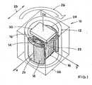
- Fig. 1shows an electric motor 10 for a small electric appliance having a rotor 12 which is shown transparent here for the better representability of the other components.
- a drawing border 50is shown in Fig. 1 only to illustrate the perspective.
- Permanent magnets 18, 20, 22, 24are fastened inside the rotor and are moved with it, with magnets 18, 20 or 22, 24 disposed next to one another each being magnetized with opposite polarities.
- the rotoris rotatably supported about the z axis, which should be indicated by the arrow 26.
- a coil 16is arranged within the rotor with an iron core 14 located therein as a stator. The coil windings are disposed in planes parallel to the Y-Z plane. In Fig.
- a permanent magnet 30 called a Lorentz magnet hereis arranged above this arrangement, wherein a magnetic field generated by the Lorentz magnet 30 would be parallel to the Z axis if it were not distorted by the influence of the coil 16 or of the permanent magnets 18, 20, 22, 24.
- the Lorentz magnet 30is also fixedly connected to the rotor 12.
- a Lorentz forceis generated in the direction of the arrow 28 on the arrangement of coil 16 and stator 14 in a manner still to be described with the help of the additional permanent magnet 30 when current is flowing in the coil. With a fixed coil 16, this means a translatory oscillatory movement of the rotor 12 together with the magnets 18, 20, 22, 24 and the Lorentz magnet 30 in the direction 28.
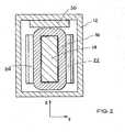
- Fig. 2shows a sectional representation in the Y-Z plane.
- the translatory oscillatory movement 28thereby arises as follows.
- the coil 16 and the iron core 14act with the permanent magnets 18, 20, 22, 24 as in an electric motor for the generation of a rotary movement when a current is flowing in the coil.
- a magnetic fluxis generated through the coil in the iron core 14.
- the surrounding permanent magnets 18, 20, 22, 24 - and thus the rotor 12 -align in accordance with the direction of flux.
- a Lorentz forceis additionally present on the conductor of the coil 16 through which current flows in the direction of the vector product from the magnetic flux and the direction of the conductor through which current flows multiplied by the length of the conductor, through which current flows and which is exposed to the magnetic flux, and by the current.
- the Lorentz magnet 30is aligned in the embodiment of Figs. 1 and 2 such that it generates magnetic flux substantially in the direction of the axis of rotation (z axis).
- the coil windings of the coil 16are disposed in the image plane of Fig. 2 . In particular in the region of the coil 16 at the top in Fig.
- the conductors of the coil windings through which current flows accordinglyextend in the Y direction. If current accordingly flows through the coil 16, a relative force effect arises between the coil and the Lorentz magnet 30 in the x direction. With a fixedly held coil 16, the Lorentz magnet 30 therefore moves together with the rotor 12 in the x direction.
- the current direction through the coilchanges periodically in the coordinate system of the rotor 12 or of the Lorentz magnet 30 fixedly connected thereto so that a translatory oscillatory movement arises.
- the current directionalso changes relative to the magnetic flux generated by the Lorentz magnet so that a translatory oscillatory movement also arises then.
- the brush head of an electric toothbrush or the shaving head of an electric shaveris connected to the rotor 12, this not only carries out the rotary movement 26 of the rotor 12, but also the translatory movement in the direction 28.
- Fig. 3shows a modified embodiment in which two Lorentz magnets 30 are provided above and beneath the coil 16. The force effect is thereby substantially doubled.
- the Lorentz force in arrangements of Figs. 1 to 3in particular acts on the conductors through which current flows of the here shorter coil side and which are aligned parallel to the y direction.
- magnet segments 32, 34are arranged as Lorentz magnets between the permanent magnets 18, 20, 22, 24 in addition to the permanent magnets 18, 20, 22, 24 generating the rotary movement. They accordingly generate magnetic flux through the coil 16 in the y direction. This magnetic flux therefore in particular acts on the here longer coil sections which extend parallel to the z direction in the representation of Fig. 4 .
- the magnetic segments 32, 34 in this embodimenthave substantially the same polarity as the permanent magnets 18 and 22.
- Arrows 40should schematically indicate the relative polarity of the respective permanent magnets 18, 20, 22, 24 or of the Lorentz magnets 32, 34, with the arrows indicating the direction from south pole to north pole. If, for example, the south poles are arranged radially inwardly in the magnet segments 32, 34 and the permanent magnets 18, 22, the north poles are radially inwardly arranged in the permanent magnets 20, 24.
- a Lorentz forceis generated on the conductors of the coil 16 through which current flows in the direction x. This is aligned in the direction 28 in accordance with the cross product for the determination of the Lorentz force.
- the rotor 12With a fixedly held coil 16 or a fixedly held iron core 14, the rotor 12 therefore not only moves rotarily in the direction 26, but also translatorily in the direction 28.
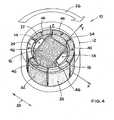
- Fig. 5shows a cross-section through the arrangement of Fig. 4 in the X-Y plane. Additionally, the directions of the magnetic field lines are indicated here which result from the arrangement of the permanent magnets 18, 20, 22, 24 and of the Lorentz magnets 32 and 34. As can be recognized particularly clearly in the representation of Fig. 5 , the Lorentz magnet 34 forms part of a larger magnetic element which takes over the function of the permanent magnets 18, 22 and of the Lorentz magnet 34 and whose polarity for all three segments 18, 22, 34 faces in the same direction either radially outwardly or radially inwardly.
- the polarity of the Lorentz magnet 32faces in the same direction in the radial direction (that is, for example, outwardly when the polarity of the permanent magnets 18, 22 and of the Lorentz magnet 34 is directed outwardly)
- the polarity of the permanent magnets 20, 24is oppositely directed in the radial direction.
- the embodiment of Fig. 6is a combination of the embodiments of Fig. 1 and Fig. 4 .
- radially arranged Lorentz magnets 32, 34, and an axially arranged Lorentz magnet 30are provided.
- a suitable selection of the strength of these magnetsallows a flexible setting of the Lorentz force and thus of the translatory force.
- either the translatory oscillatory movement or the rotary oscillatory movementcan be excited by a corresponding selection of the frequency of the current fed into the coil.
- the frequency fed inis selected in accordance with the resonant frequency of the respective oscillatory movement.
- a selection of a corresponding mixed frequency or irradiation of a plurality of frequenciescan be used to set the strength of the oscillatory movements relative to one another.
- the embodiments in accordance with the inventionreduce the number of the individual parts required for the construction of the drive and enable a compact construction shape of the drive unit.
- the achievable torques of the rotary movement and the forces in translatory directionscan be set freely.
- the torques and forcesare scaled approximately linearly with the length of the motor and the translatory movement proves to be largely independent of the angular position of the rotary movement.
- the noise developmentis lower due to the omission of a transmission for the generation of an additional translatory movement.
Landscapes
- Engineering & Computer Science (AREA)
- Life Sciences & Earth Sciences (AREA)
- Forests & Forestry (AREA)
- Mechanical Engineering (AREA)
- Power Engineering (AREA)
- Reciprocating, Oscillating Or Vibrating Motors (AREA)
- Dry Shavers And Clippers (AREA)
- Apparatuses For Generation Of Mechanical Vibrations (AREA)
Description
- The invention relates to an electric motor for a small electric appliance. The invention furthermore relates to a small electric appliance having such a motor.
- Electric motors are known which can generate a rotary and a linear oscillatory movement and are used, for example, for electric toothbrushes.
- Known motors provide for this purpose a DC motor and a subsequent translation of the rotary movement into an additional linear movement with the help of a transmission or the generation of the linear movement in a first drive unit and the generation of the rotary movement in a second drive unit.
- An electric motor described in
WO 2005/062445 has two oscillatory motor components and a magnet arrangement with a plurality of permanent magnets. A coil generates a magnetic field which is provided for the generation of a force for the excitation of a linear oscillatory movement of an oscillatory component by interaction with the magnet arrangement. The interaction of the magnetic field generated by the coil and the magnet arrangement additionally generates a torque for the generation of a rotary oscillatory movement of a second oscillatory motor component. - Document
WO 2005/062445 A1 describes a motor in accordance with the preamble of claim 1. DocumentUS 6 429 611 B1 describes a similar motor having a first magnet arrangement that is arranged to take the function of the second magnet arrangement of the electric motor in accordance with the preamble of claim 1. - It is the object of the present invention to provide a compact and cost-effective electric motor of simple construction for small appliances.
- This object is satisfied by an electric motor having the features of claim 1. A small electric appliance having an electric motor in accordance with the invention is the subject of
claim 10. - An electric motor in accordance with the invention for a small electric appliance has a rotor and a stator and a coil for the generation of a magnetic field. A first magnet arrangement has at least one permanent magnet which, by interaction with a magnetic field generated with the coil, generates a force for the excitation of a rotary movement of the rotor. An electric motor in accordance with the invention is in particular characterized in that a second magnet arrangement is provided which comprises at least one second permanent magnet which is arranged such that a translatory oscillatory movement of the rotor is effected by the Lorentz force acting in the field of the second permanent magnet on the conductors of the coil through which current flows.
- Two different physical principles are combined with the help of the electric motor in accordance with the invention in order to generate the rotary movement, on the one hand, and the translatory movement, on the other hand. The rotary movement is generated using a first magnet arrangement and a coil in a manner known per se. An iron core with a coil in which a magnetic flux is generated with the help of the coil can, for example, be provided as a stator in the center of the drive. Permanent magnets arranged in a surrounding manner align in accordance with the flux direction so that a rotary movement of the surrounding rotor takes place.
- In accordance with claim 1, a second magnet arrangement is provided in accordance with the invention which has at least one permanent magnet which generates a magnetic Lorentz force on the conductors of the coil through which current flows. With a fixed coil, this means a relative movement of the at least one second permanent magnet in the translatory direction. A compact, simple and cost-effective embodiment for an electric motor for a small appliance is possible by the utilization of the Lorentz force of a magnet arrangement on the conductors of the coil through which current flows. The individual parts for the construction of the drive are reduced.
- It is generally possible to couple the relative translatory movement of the at least one second permanent magnet and the rotary movement of the rotor to obtain a coupled rotary and linear movement. It is, however, particularly simple if the second permanent magnet moves together with the rotor, in particular if it is connected to it. The rotary movement of the rotor and the linear movement of the at least second permanent magnet are then automatically combined to a coupled movement.
- In accordance with a first alternative of the invention, at least one second permanent magnet is arranged such that it generates a field which is aligned substantially parallel to the axis of rotation of the rotor if no other magnetic field influencing fields are present. This can in particular be achieved in a simple manner if the at least one second permanent magnet is disposed above or beneath the coil in symmetrical alignment with the axis of rotation of the rotor. With such an arrangement, provision can, for example, be made that a second permanent magnet is provided both above and beneath the coil to double the desired effect. The magnetic flux which is generated by such an arrangement of the at least one second permanent magnet in particular acts on the conductor regions of the coil aligned perpendicular to the axis of rotation.
- In accordance with a second alternative of the invention, the at least one second permanent magnet is arranged such that it generates a field substantially radially to the axis of rotation of the rotor if no other magnet field-influencing elements were present. The magnetic flux which is generated by this arrangement of the at least one second permanent magnet in particular acts on the conductor regions of the coil aligned parallel to the axis of rotation.
- A particularly space-saving arrangement is that the at least one permanent magnet of the second magnet arrangement is arranged between the permanent magnets of the first magnet arrangement.
- Both described embodiments can also be combined with one another, with in particular a second magnet arrangement therefore being provided which has at least one second permanent magnet which generates a field which is aligned substantially radially to the axis of rotation of the rotor and has at least one additional permanent magnet whose field is aligned substantially parallel to the axis of rotation of the rotor. In this manner, the strength of the Lorentz force, and thus, for example, the amplitude of the translatory oscillatory movement, can be set very flexibly.
- With a suitable arrangement of the individual segments of the permanent magnets of the first and second magnet arrangements, it is also possible that at least a part of the second magnet arrangement is in one piece with a part of the first magnet arrangement.
- Electric motors in accordance with the invention can be designed to carry out a translatory oscillatory movement and a continuous rotary movement. The invention is, however, particularly expedient when the rotary movement also is an oscillatory movement.
- When the rotary oscillatory movement and the translatory oscillatory movement have different resonant frequencies, the individual oscillatory movements can also be controlled separately by feeding in current of correspondingly selected frequencies. Feeding in mixed frequencies effects a correspondingly distributed rotary or translatory oscillatory movement.
- It is generally possible that an optionally present soft magnetic core (of iron, for example) of the coil is, for example, rotatably supported and the permanent magnets of the electric motor are still. The core then forms the rotor which also carries out the translatory oscillatory movement. It is, however, more expedient and simpler if the core of the coil is part of the stator of the electric motor and if the rotor includes the first magnet arrangement. In this respect, an arrangement is particularly compact in which the coil is arranged inside the first magnet arrangement.
- With the electric motors in accordance with the invention, the arrangement is preferably selected such that the translatory movement is perpendicular to the axis of rotation.
- The electric motor in accordance with the invention is particularly suitable for the drive of small electric appliances such as electric toothbrushes in which the brush head carries out a translatory oscillatory movement and a rotary oscillatory movement or for razors where the shaving head carries out a translatory and a rotary oscillatory movement.
- The invention will be explained with reference to the enclosed schematic Figures in detail which show embodiments in accordance with the invention by way of example. There are shown:
- Fig. 1
- a perspective schematic view of an electric motor in accordance with the invention in a partly transparent representation;
- Fig. 2
- a sectional view in the Y-Z plane indicated in
Fig. 1 ; - Fig. 3
- a perspective schematic view of another embodiment in accordance with the invention in a partly transparent representation;
- Fig. 4
- a perspective schematic view of a further embodiment in accordance with the invention in a partly transparent representation;
- Fig. 5
- a cross-sectional view in the X-Y plane indicated in
Fig. 4 with indicated magnetic field lines; and - Fig. 6
- a perspective schematic view of yet a further embodiment in accordance with the invention in a partly transparent representation.
Fig. 1 shows anelectric motor 10 for a small electric appliance having arotor 12 which is shown transparent here for the better representability of the other components. Adrawing border 50 is shown inFig. 1 only to illustrate the perspective.Permanent magnets magnets arrow 26. Acoil 16 is arranged within the rotor with aniron core 14 located therein as a stator. The coil windings are disposed in planes parallel to the Y-Z plane. InFig. 1 , apermanent magnet 30 called a Lorentz magnet here is arranged above this arrangement, wherein a magnetic field generated by theLorentz magnet 30 would be parallel to the Z axis if it were not distorted by the influence of thecoil 16 or of thepermanent magnets Lorentz magnet 30 is also fixedly connected to therotor 12. A Lorentz force is generated in the direction of thearrow 28 on the arrangement ofcoil 16 andstator 14 in a manner still to be described with the help of the additionalpermanent magnet 30 when current is flowing in the coil. With a fixedcoil 16, this means a translatory oscillatory movement of therotor 12 together with themagnets Lorentz magnet 30 in thedirection 28.Fig. 2 shows a sectional representation in the Y-Z plane.- The translatory
oscillatory movement 28 thereby arises as follows. In a manner known per se, thecoil 16 and theiron core 14 act with thepermanent magnets iron core 14. The surroundingpermanent magnets - In addition to the forces which arise which result in the rotary movement, a Lorentz force is additionally present on the conductor of the
coil 16 through which current flows in the direction of the vector product from the magnetic flux and the direction of the conductor through which current flows multiplied by the length of the conductor, through which current flows and which is exposed to the magnetic flux, and by the current. TheLorentz magnet 30 is aligned in the embodiment ofFigs. 1 and2 such that it generates magnetic flux substantially in the direction of the axis of rotation (z axis). In this respect, the coil windings of thecoil 16 are disposed in the image plane ofFig. 2 . In particular in the region of thecoil 16 at the top inFig. 2 and in direct proximity to theLorentz magnet 30, the conductors of the coil windings through which current flows accordingly extend in the Y direction. If current accordingly flows through thecoil 16, a relative force effect arises between the coil and theLorentz magnet 30 in the x direction. With a fixedly heldcoil 16, theLorentz magnet 30 therefore moves together with therotor 12 in the x direction. - If the
rotor 12 rotates continuously, the current direction through the coil changes periodically in the coordinate system of therotor 12 or of theLorentz magnet 30 fixedly connected thereto so that a translatory oscillatory movement arises. With a suitable polarity reversal of the current direction for the generation of a rotary oscillatory movement in or opposite to thedirection 26, the current direction also changes relative to the magnetic flux generated by the Lorentz magnet so that a translatory oscillatory movement also arises then. - If, for example, the brush head of an electric toothbrush or the shaving head of an electric shaver is connected to the
rotor 12, this not only carries out therotary movement 26 of therotor 12, but also the translatory movement in thedirection 28. Fig. 3 shows a modified embodiment in which twoLorentz magnets 30 are provided above and beneath thecoil 16. The force effect is thereby substantially doubled.- The Lorentz force in arrangements of
Figs. 1 to 3 in particular acts on the conductors through which current flows of the here shorter coil side and which are aligned parallel to the y direction. - In an embodiment of
Fig. 4 ,magnet segments permanent magnets permanent magnets coil 16 in the y direction. This magnetic flux therefore in particular acts on the here longer coil sections which extend parallel to the z direction in the representation ofFig. 4 . - The
magnetic segments permanent magnets Arrows 40 should schematically indicate the relative polarity of the respectivepermanent magnets Lorentz magnets magnet segments permanent magnets permanent magnets - In an arrangement of
Fig. 4 , a Lorentz force is generated on the conductors of thecoil 16 through which current flows in the direction x. This is aligned in thedirection 28 in accordance with the cross product for the determination of the Lorentz force. With a fixedly heldcoil 16 or a fixedly heldiron core 14, therotor 12 therefore not only moves rotarily in thedirection 26, but also translatorily in thedirection 28. Fig. 5 shows a cross-section through the arrangement ofFig. 4 in the X-Y plane. Additionally, the directions of the magnetic field lines are indicated here which result from the arrangement of thepermanent magnets Lorentz magnets Fig. 5 , theLorentz magnet 34 forms part of a larger magnetic element which takes over the function of thepermanent magnets Lorentz magnet 34 and whose polarity for all threesegments - Whereas the polarity of the
Lorentz magnet 32 faces in the same direction in the radial direction (that is, for example, outwardly when the polarity of thepermanent magnets Lorentz magnet 34 is directed outwardly), the polarity of thepermanent magnets - The embodiment of
Fig. 6 is a combination of the embodiments ofFig. 1 andFig. 4 . Here, radially arrangedLorentz magnets Lorentz magnet 30 are provided. A suitable selection of the strength of these magnets allows a flexible setting of the Lorentz force and thus of the translatory force. - In all embodiments, either the translatory oscillatory movement or the rotary oscillatory movement can be excited by a corresponding selection of the frequency of the current fed into the coil. For this purpose, the frequency fed in is selected in accordance with the resonant frequency of the respective oscillatory movement. A selection of a corresponding mixed frequency or irradiation of a plurality of frequencies can be used to set the strength of the oscillatory movements relative to one another.
- The embodiments in accordance with the invention reduce the number of the individual parts required for the construction of the drive and enable a compact construction shape of the drive unit. Depending on the construction design of the drive, the achievable torques of the rotary movement and the forces in translatory directions can be set freely. The torques and forces are scaled approximately linearly with the length of the motor and the translatory movement proves to be largely independent of the angular position of the rotary movement. The noise development is lower due to the omission of a transmission for the generation of an additional translatory movement.
- 10
- electric motor
- 12
- rotor
- 14
- iron core
- 16
- coil
- 18, 20, 22, 24
- permanent magnet
- 26
- rotary movement
- 28
- translatory oscillatory movement
- 30, 32, 34
- Lorentz magnet
- 36
- magnetic flux
- 40
- polarity
- 50
- drawing border
Claims (12)
- An electric motor (10) for a small electric appliance, comprising- a rotor (12) and a stator;- a coil (16) for the generation of a magnetic field;- a first magnet arrangement having at least one first permanent magnet (18, 20, 22, 24) which, by interaction with a magnetic field generated using the coil (16), generates a force for the excitation of a rotary movement (26) of the rotor (12) about an axis of rotation,- a second magnet arrangement which comprises at least one second permanent magnet (30, 32, 34) which is arranged such that a translatory oscillatory movement (28) of the rotor (12) is effected by the Lorentz force acting in the field of the second permanent magnet on the conductors of the coil (16) through which current flows,characterized in that- either the at least one second permanent magnet (30) is arranged such that its field not influenced by other fields would be aligned substantially parallel to the axis of rotation of the rotor (12), or- the at least one second permanent magnet (32, 34) is arranged such that its field not influenced by other fields would be aligned substantially radially to the axis of rotation of the rotor (12) and the first magnet arrangement comprises a plurality of permanent magnets (18, 20, 22, 24) which are arranged concentrically to the axis of rotation and the at least one permanent magnet (32,- 34) of the second magnet arrangement is arranged between permanent magnets (18, 20, 22, 24) of the first magnet arrangement in the circumferential direction of a circular shape defined by the concentric arrangement of the permanent magnets (18, 20, 22, 24) of the first magnet arrangement.
- An electric motor in accordance with the first alternative of claim 1,characterized in that the at least one second permanent magnet (30) is arranged above or beneath the coil (16) in the direction of the axis of rotation.
- An electric motor in accordance with the first alternative of claim 1,characterized in that the second magnet arrangement moves with the rotor (12).
- An electric motor in accordance with claim 3,characterized in that the second magnet arrangement is fixedly connected to the rotor.
- An electric motor in accordance with the second alternative of claim 1,characterized in that the second magnet arrangement (30, 32, 34) includes at least one additional permanent magnet (30) which is arranged such that its field not influenced by other fields would be aligned substantially parallel to the axis of rotation of the rotor (12), preferablyin that the at least one additional magnet (30) is arranged above or beneath the coil (16) in the direction of the axis of rotation.
- An electric motor in accordance with any one of the preceding claims,characterized in that at least one permanent magnet (34) of the second magnet arrangement is made in one piece with at least one permanent magnet (18, 22) of the first magnet arrangement.
- An electric motor in accordance with any one of the preceding claims,characterized in that the at least one first permanent magnet (18, 20, 22, 24) and the coil (16) are designed and arranged such that the at least one first permanent magnet (18, 20, 22, 24), by interaction with a magnetic field generated using the coil (16), generates a force for the excitation of a rotary oscillatory movement of the rotor (12).
- An electric motor in accordance with claim 7,characterized in that the rotary oscillatory movement and the translatory oscillatory movement have different resonant frequencies.
- An electric motor in accordance with any one of the preceding claims,characterized in that the rotor (12) includes the first magnet arrangement (18, 20, 22, 24), with the coil (16) preferably being arranged inside the first magnet arrangement (18, 20, 22, 24).
- A small electric appliance comprising an electric motor having the features of any one of the preceding claims for the excitation of a translatory oscillatory movement and of a rotary movement.
- A small electric appliance comprising an electric motor in accordance with claim 10,characterized in that it is an electric toothbrush with a brush head and the electric motor serves for the generation of a translatory oscillatory movement of the brush head and of a rotary movement of the brush head.
- A small electric appliance comprising an electric motor in accordance with claim 10,characterized in that it is an electric razor with a shaving head and the electric motor serves for the generation of a transitory oscillatory movement of the shaving head and of a rotary movement of the shaving head.
Priority Applications (7)
| Application Number | Priority Date | Filing Date | Title |
|---|---|---|---|
| EP09007760.3AEP2262083B1 (en) | 2009-06-12 | 2009-06-12 | Electric motor for a small electric appliance |
| ES09007760.3TES2549982T3 (en) | 2009-06-12 | 2009-06-12 | Electric motor for a small electrical appliance |
| CA2765277ACA2765277A1 (en) | 2009-06-12 | 2010-06-10 | Electric motor for a small electric appliance |
| JP2012513733AJP5579835B2 (en) | 2009-06-12 | 2010-06-10 | Electric motor for small electric appliances |
| PCT/IB2010/052594WO2010143156A1 (en) | 2009-06-12 | 2010-06-10 | Electric motor for a small electric appliance |
| CN201080025112.2ACN102460917B (en) | 2009-06-12 | 2010-06-10 | Electric motor for a small electric appliance |
| US13/311,790US20120110856A1 (en) | 2009-06-12 | 2011-12-06 | Electric motor for an electric appliance |
Applications Claiming Priority (1)
| Application Number | Priority Date | Filing Date | Title |
|---|---|---|---|
| EP09007760.3AEP2262083B1 (en) | 2009-06-12 | 2009-06-12 | Electric motor for a small electric appliance |
Publications (2)
| Publication Number | Publication Date |
|---|---|
| EP2262083A1 EP2262083A1 (en) | 2010-12-15 |
| EP2262083B1true EP2262083B1 (en) | 2015-07-15 |
Family
ID=41256082
Family Applications (1)
| Application Number | Title | Priority Date | Filing Date |
|---|---|---|---|
| EP09007760.3AActiveEP2262083B1 (en) | 2009-06-12 | 2009-06-12 | Electric motor for a small electric appliance |
Country Status (7)
| Country | Link |
|---|---|
| US (1) | US20120110856A1 (en) |
| EP (1) | EP2262083B1 (en) |
| JP (1) | JP5579835B2 (en) |
| CN (1) | CN102460917B (en) |
| CA (1) | CA2765277A1 (en) |
| ES (1) | ES2549982T3 (en) |
| WO (1) | WO2010143156A1 (en) |
Families Citing this family (13)
| Publication number | Priority date | Publication date | Assignee | Title |
|---|---|---|---|---|
| US20100186234A1 (en) | 2009-01-28 | 2010-07-29 | Yehuda Binder | Electric shaver with imaging capability |
| JP5387400B2 (en)* | 2009-12-28 | 2014-01-15 | 日立工機株式会社 | Electric mower |
| US9154025B2 (en) | 2010-07-23 | 2015-10-06 | Braun Gmbh | Personal care device |
| EP2410641A1 (en) | 2010-07-23 | 2012-01-25 | Braun GmbH | Linear electric motor |
| EP2420203B1 (en) | 2010-08-19 | 2019-10-23 | Braun GmbH | Resonant motor unit and electric device with resonant motor unit |
| ES2451021T3 (en) | 2011-07-25 | 2014-03-26 | Braun Gmbh | Magnetic connection between a toothbrush handle and a brush head |
| CN103703668B (en) | 2011-07-25 | 2016-12-07 | 博朗有限公司 | Linear electro-polymer motor and the device with described linear electro-polymer motor |
| PL2550938T3 (en) | 2011-07-25 | 2015-06-30 | Braun Gmbh | Oral hygiene device |
| CN105873540B (en)* | 2013-12-30 | 2018-03-27 | 皇家飞利浦有限公司 | Actuators with grouped magnets for personal care appliances |
| CN103939574B (en)* | 2014-03-13 | 2016-08-24 | 都佳宜电器制品(深圳)有限公司 | Sound wave motor |
| US10011035B2 (en)* | 2015-02-23 | 2018-07-03 | Makita Corporation | Machining device and electric motor for the same |
| CN109330726B (en)* | 2018-09-04 | 2024-07-12 | 郗瑛琦 | Linear actuator, oral cavity cleaner and control method of oral cavity cleaner |
| CN109617306A (en)* | 2019-01-28 | 2019-04-12 | 中科(深圳)创新创意科技有限公司 | Electric toothbrush motors and toothbrushes |
Family Cites Families (9)
| Publication number | Priority date | Publication date | Assignee | Title |
|---|---|---|---|---|
| US4135119A (en)* | 1977-03-23 | 1979-01-16 | General Scanning, Inc. | Limited rotation motor |
| DE3315848A1 (en)* | 1983-04-30 | 1984-10-31 | Philips Patentverwaltung Gmbh, 2000 Hamburg | Actuator device on writing and reading units for constant correction of the spatial position of a writing or reading means, in particular a beam |
| US5928131A (en)* | 1997-11-26 | 1999-07-27 | Vascor, Inc. | Magnetically suspended fluid pump and control system |
| US6429611B1 (en)* | 2000-01-28 | 2002-08-06 | Hui Li | Rotary and linear motor |
| US6873067B2 (en)* | 2000-09-29 | 2005-03-29 | Matsushita Electric Works, Ltd. | Linear oscillator |
| EP1566879A4 (en)* | 2002-11-26 | 2008-07-09 | Matsushita Electric Works Ltd | ACTUATOR |
| DE10350447A1 (en)* | 2003-10-29 | 2005-06-02 | Braun Gmbh | Drive unit for generating an oscillating movement for small electrical appliances |
| DE10355446A1 (en)* | 2003-11-27 | 2005-06-30 | Braun Gmbh | Electric motor for a small electrical appliance |
| WO2007020599A2 (en)* | 2005-08-16 | 2007-02-22 | Koninklijke Philips Electronics, N.V. | Resonant actuator for a personal care appliance having a programmable actuation capability |
- 2009
- 2009-06-12EPEP09007760.3Apatent/EP2262083B1/enactiveActive
- 2009-06-12ESES09007760.3Tpatent/ES2549982T3/enactiveActive
- 2010
- 2010-06-10WOPCT/IB2010/052594patent/WO2010143156A1/enactiveApplication Filing
- 2010-06-10JPJP2012513733Apatent/JP5579835B2/ennot_activeExpired - Fee Related
- 2010-06-10CNCN201080025112.2Apatent/CN102460917B/enactiveActive
- 2010-06-10CACA2765277Apatent/CA2765277A1/ennot_activeAbandoned
- 2011
- 2011-12-06USUS13/311,790patent/US20120110856A1/ennot_activeAbandoned
Also Published As
| Publication number | Publication date |
|---|---|
| CA2765277A1 (en) | 2010-12-16 |
| US20120110856A1 (en) | 2012-05-10 |
| JP2012529878A (en) | 2012-11-22 |
| CN102460917A (en) | 2012-05-16 |
| WO2010143156A1 (en) | 2010-12-16 |
| CN102460917B (en) | 2014-11-19 |
| ES2549982T3 (en) | 2015-11-03 |
| EP2262083A1 (en) | 2010-12-15 |
| JP5579835B2 (en) | 2014-08-27 |
Similar Documents
| Publication | Publication Date | Title |
|---|---|---|
| EP2262083B1 (en) | Electric motor for a small electric appliance | |
| US11784523B2 (en) | Multi-tunnel electric motor/generator | |
| EP2441159B1 (en) | Small electrical appliance and electric motor drive unit for a small electrical appliance | |
| US5117142A (en) | Permanent magnetized synchronous machine designed according to the transverse flux principle | |
| US7915777B2 (en) | Ring coil motor | |
| US9685828B2 (en) | Electric machine with multiple air gaps and a 3D magnetic flux | |
| US20160380496A1 (en) | Multi-tunnel electric motor/generator | |
| CA1273980A (en) | Electrical machine with unequal pole faces | |
| US7834503B2 (en) | Immersed windings, monopole field, electromagnetic rotating machine | |
| US9496757B2 (en) | Electric machine with intermediate pieces having multiple air gaps and a 3D magnetic flux | |
| EP3089702B1 (en) | Actuator with grouped magnets for personal care appliance | |
| US10357346B2 (en) | Actuator with enhanced magnetic spring function for personal care appliance | |
| JP2013066360A (en) | Switched reluctance motor | |
| JP2009254021A (en) | Motor | |
| EP0431178B1 (en) | Synchronous machine | |
| JP6609368B2 (en) | Hollow single-phase induction motor | |
| JP2005020885A (en) | Rotary linear dc motor | |
| US5952759A (en) | Brushless synchronous rotary electrical machine | |
| US20200028424A1 (en) | Permanent magnet three phase machine for high speed applications having low vibration and low resistive losses | |
| JP7689700B1 (en) | Magnetic rotating device, electric motor, generator and motor-generator | |
| KR101724098B1 (en) | Assembled contactless motor and inverter unit having brush and commutator | |
| KR20230172104A (en) | Rotor of motor and motor having the same | |
| WO2022148994A1 (en) | Bipolar induction electric machine | |
| JP2014207799A (en) | Brushless dc motor, lens barrel, and imaging device | |
| JPS63144751A (en) | Motor |
Legal Events
| Date | Code | Title | Description |
|---|---|---|---|
| PUAI | Public reference made under article 153(3) epc to a published international application that has entered the european phase | Free format text:ORIGINAL CODE: 0009012 | |
| AK | Designated contracting states | Kind code of ref document:A1 Designated state(s):AT BE BG CH CY CZ DE DK EE ES FI FR GB GR HR HU IE IS IT LI LT LU LV MC MK MT NL NO PL PT RO SE SI SK TR | |
| AX | Request for extension of the european patent | Extension state:AL BA RS | |
| 17P | Request for examination filed | Effective date:20110607 | |
| 17Q | First examination report despatched | Effective date:20110630 | |
| GRAP | Despatch of communication of intention to grant a patent | Free format text:ORIGINAL CODE: EPIDOSNIGR1 | |
| INTG | Intention to grant announced | Effective date:20150211 | |
| GRAS | Grant fee paid | Free format text:ORIGINAL CODE: EPIDOSNIGR3 | |
| GRAA | (expected) grant | Free format text:ORIGINAL CODE: 0009210 | |
| AK | Designated contracting states | Kind code of ref document:B1 Designated state(s):AT BE BG CH CY CZ DE DK EE ES FI FR GB GR HR HU IE IS IT LI LT LU LV MC MK MT NL NO PL PT RO SE SI SK TR | |
| REG | Reference to a national code | Ref country code:CH Ref legal event code:EP Ref country code:GB Ref legal event code:FG4D | |
| REG | Reference to a national code | Ref country code:IE Ref legal event code:FG4D | |
| REG | Reference to a national code | Ref country code:AT Ref legal event code:REF Ref document number:737223 Country of ref document:AT Kind code of ref document:T Effective date:20150815 | |
| REG | Reference to a national code | Ref country code:DE Ref legal event code:R096 Ref document number:602009032190 Country of ref document:DE | |
| REG | Reference to a national code | Ref country code:SE Ref legal event code:TRGR Ref country code:ES Ref legal event code:FG2A Ref document number:2549982 Country of ref document:ES Kind code of ref document:T3 Effective date:20151103 | |
| REG | Reference to a national code | Ref country code:AT Ref legal event code:MK05 Ref document number:737223 Country of ref document:AT Kind code of ref document:T Effective date:20150715 | |
| REG | Reference to a national code | Ref country code:NL Ref legal event code:FP | |
| REG | Reference to a national code | Ref country code:LT Ref legal event code:MG4D | |
| PG25 | Lapsed in a contracting state [announced via postgrant information from national office to epo] | Ref country code:LV Free format text:LAPSE BECAUSE OF FAILURE TO SUBMIT A TRANSLATION OF THE DESCRIPTION OR TO PAY THE FEE WITHIN THE PRESCRIBED TIME-LIMIT Effective date:20150715 Ref country code:GR Free format text:LAPSE BECAUSE OF FAILURE TO SUBMIT A TRANSLATION OF THE DESCRIPTION OR TO PAY THE FEE WITHIN THE PRESCRIBED TIME-LIMIT Effective date:20151016 Ref country code:NO Free format text:LAPSE BECAUSE OF FAILURE TO SUBMIT A TRANSLATION OF THE DESCRIPTION OR TO PAY THE FEE WITHIN THE PRESCRIBED TIME-LIMIT Effective date:20151015 Ref country code:FI Free format text:LAPSE BECAUSE OF FAILURE TO SUBMIT A TRANSLATION OF THE DESCRIPTION OR TO PAY THE FEE WITHIN THE PRESCRIBED TIME-LIMIT Effective date:20150715 Ref country code:LT Free format text:LAPSE BECAUSE OF FAILURE TO SUBMIT A TRANSLATION OF THE DESCRIPTION OR TO PAY THE FEE WITHIN THE PRESCRIBED TIME-LIMIT Effective date:20150715 | |
| PG25 | Lapsed in a contracting state [announced via postgrant information from national office to epo] | Ref country code:HR Free format text:LAPSE BECAUSE OF FAILURE TO SUBMIT A TRANSLATION OF THE DESCRIPTION OR TO PAY THE FEE WITHIN THE PRESCRIBED TIME-LIMIT Effective date:20150715 Ref country code:AT Free format text:LAPSE BECAUSE OF FAILURE TO SUBMIT A TRANSLATION OF THE DESCRIPTION OR TO PAY THE FEE WITHIN THE PRESCRIBED TIME-LIMIT Effective date:20150715 Ref country code:PL Free format text:LAPSE BECAUSE OF FAILURE TO SUBMIT A TRANSLATION OF THE DESCRIPTION OR TO PAY THE FEE WITHIN THE PRESCRIBED TIME-LIMIT Effective date:20150715 Ref country code:PT Free format text:LAPSE BECAUSE OF FAILURE TO SUBMIT A TRANSLATION OF THE DESCRIPTION OR TO PAY THE FEE WITHIN THE PRESCRIBED TIME-LIMIT Effective date:20151116 | |
| REG | Reference to a national code | Ref country code:DE Ref legal event code:R097 Ref document number:602009032190 Country of ref document:DE | |
| PG25 | Lapsed in a contracting state [announced via postgrant information from national office to epo] | Ref country code:SK Free format text:LAPSE BECAUSE OF FAILURE TO SUBMIT A TRANSLATION OF THE DESCRIPTION OR TO PAY THE FEE WITHIN THE PRESCRIBED TIME-LIMIT Effective date:20150715 Ref country code:CZ Free format text:LAPSE BECAUSE OF FAILURE TO SUBMIT A TRANSLATION OF THE DESCRIPTION OR TO PAY THE FEE WITHIN THE PRESCRIBED TIME-LIMIT Effective date:20150715 Ref country code:DK Free format text:LAPSE BECAUSE OF FAILURE TO SUBMIT A TRANSLATION OF THE DESCRIPTION OR TO PAY THE FEE WITHIN THE PRESCRIBED TIME-LIMIT Effective date:20150715 Ref country code:IT Free format text:LAPSE BECAUSE OF FAILURE TO SUBMIT A TRANSLATION OF THE DESCRIPTION OR TO PAY THE FEE WITHIN THE PRESCRIBED TIME-LIMIT Effective date:20150715 Ref country code:EE Free format text:LAPSE BECAUSE OF FAILURE TO SUBMIT A TRANSLATION OF THE DESCRIPTION OR TO PAY THE FEE WITHIN THE PRESCRIBED TIME-LIMIT Effective date:20150715 | |
| PLBE | No opposition filed within time limit | Free format text:ORIGINAL CODE: 0009261 | |
| STAA | Information on the status of an ep patent application or granted ep patent | Free format text:STATUS: NO OPPOSITION FILED WITHIN TIME LIMIT | |
| PG25 | Lapsed in a contracting state [announced via postgrant information from national office to epo] | Ref country code:RO Free format text:LAPSE BECAUSE OF FAILURE TO SUBMIT A TRANSLATION OF THE DESCRIPTION OR TO PAY THE FEE WITHIN THE PRESCRIBED TIME-LIMIT Effective date:20150715 | |
| REG | Reference to a national code | Ref country code:FR Ref legal event code:PLFP Year of fee payment:8 | |
| 26N | No opposition filed | Effective date:20160418 | |
| PG25 | Lapsed in a contracting state [announced via postgrant information from national office to epo] | Ref country code:IS Free format text:LAPSE BECAUSE OF FAILURE TO SUBMIT A TRANSLATION OF THE DESCRIPTION OR TO PAY THE FEE WITHIN THE PRESCRIBED TIME-LIMIT Effective date:20150715 | |
| PGFP | Annual fee paid to national office [announced via postgrant information from national office to epo] | Ref country code:ES Payment date:20160607 Year of fee payment:8 Ref country code:CH Payment date:20160525 Year of fee payment:8 | |
| PG25 | Lapsed in a contracting state [announced via postgrant information from national office to epo] | Ref country code:SI Free format text:LAPSE BECAUSE OF FAILURE TO SUBMIT A TRANSLATION OF THE DESCRIPTION OR TO PAY THE FEE WITHIN THE PRESCRIBED TIME-LIMIT Effective date:20150715 | |
| PGFP | Annual fee paid to national office [announced via postgrant information from national office to epo] | Ref country code:SE Payment date:20160607 Year of fee payment:8 | |
| PG25 | Lapsed in a contracting state [announced via postgrant information from national office to epo] | Ref country code:BE Free format text:LAPSE BECAUSE OF FAILURE TO SUBMIT A TRANSLATION OF THE DESCRIPTION OR TO PAY THE FEE WITHIN THE PRESCRIBED TIME-LIMIT Effective date:20150715 | |
| PG25 | Lapsed in a contracting state [announced via postgrant information from national office to epo] | Ref country code:MC Free format text:LAPSE BECAUSE OF FAILURE TO SUBMIT A TRANSLATION OF THE DESCRIPTION OR TO PAY THE FEE WITHIN THE PRESCRIBED TIME-LIMIT Effective date:20150715 | |
| REG | Reference to a national code | Ref country code:IE Ref legal event code:MM4A | |
| REG | Reference to a national code | Ref country code:FR Ref legal event code:PLFP Year of fee payment:9 | |
| PG25 | Lapsed in a contracting state [announced via postgrant information from national office to epo] | Ref country code:IE Free format text:LAPSE BECAUSE OF NON-PAYMENT OF DUE FEES Effective date:20160612 | |
| REG | Reference to a national code | Ref country code:SE Ref legal event code:EUG | |
| REG | Reference to a national code | Ref country code:CH Ref legal event code:PL | |
| PG25 | Lapsed in a contracting state [announced via postgrant information from national office to epo] | Ref country code:SE Free format text:LAPSE BECAUSE OF NON-PAYMENT OF DUE FEES Effective date:20170613 | |
| PG25 | Lapsed in a contracting state [announced via postgrant information from national office to epo] | Ref country code:LI Free format text:LAPSE BECAUSE OF NON-PAYMENT OF DUE FEES Effective date:20170630 Ref country code:CH Free format text:LAPSE BECAUSE OF NON-PAYMENT OF DUE FEES Effective date:20170630 | |
| REG | Reference to a national code | Ref country code:FR Ref legal event code:PLFP Year of fee payment:10 | |
| PG25 | Lapsed in a contracting state [announced via postgrant information from national office to epo] | Ref country code:HU Free format text:LAPSE BECAUSE OF FAILURE TO SUBMIT A TRANSLATION OF THE DESCRIPTION OR TO PAY THE FEE WITHIN THE PRESCRIBED TIME-LIMIT; INVALID AB INITIO Effective date:20090612 Ref country code:CY Free format text:LAPSE BECAUSE OF FAILURE TO SUBMIT A TRANSLATION OF THE DESCRIPTION OR TO PAY THE FEE WITHIN THE PRESCRIBED TIME-LIMIT Effective date:20150715 | |
| PG25 | Lapsed in a contracting state [announced via postgrant information from national office to epo] | Ref country code:TR Free format text:LAPSE BECAUSE OF FAILURE TO SUBMIT A TRANSLATION OF THE DESCRIPTION OR TO PAY THE FEE WITHIN THE PRESCRIBED TIME-LIMIT Effective date:20150715 Ref country code:MK Free format text:LAPSE BECAUSE OF FAILURE TO SUBMIT A TRANSLATION OF THE DESCRIPTION OR TO PAY THE FEE WITHIN THE PRESCRIBED TIME-LIMIT Effective date:20150715 Ref country code:MT Free format text:LAPSE BECAUSE OF NON-PAYMENT OF DUE FEES Effective date:20160630 Ref country code:LU Free format text:LAPSE BECAUSE OF NON-PAYMENT OF DUE FEES Effective date:20160612 | |
| PG25 | Lapsed in a contracting state [announced via postgrant information from national office to epo] | Ref country code:BG Free format text:LAPSE BECAUSE OF FAILURE TO SUBMIT A TRANSLATION OF THE DESCRIPTION OR TO PAY THE FEE WITHIN THE PRESCRIBED TIME-LIMIT Effective date:20150715 | |
| REG | Reference to a national code | Ref country code:ES Ref legal event code:FD2A Effective date:20181112 | |
| PG25 | Lapsed in a contracting state [announced via postgrant information from national office to epo] | Ref country code:ES Free format text:LAPSE BECAUSE OF NON-PAYMENT OF DUE FEES Effective date:20170613 | |
| P01 | Opt-out of the competence of the unified patent court (upc) registered | Effective date:20230430 | |
| PGFP | Annual fee paid to national office [announced via postgrant information from national office to epo] | Ref country code:NL Payment date:20250516 Year of fee payment:17 | |
| PGFP | Annual fee paid to national office [announced via postgrant information from national office to epo] | Ref country code:DE Payment date:20250429 Year of fee payment:17 | |
| PGFP | Annual fee paid to national office [announced via postgrant information from national office to epo] | Ref country code:GB Payment date:20250501 Year of fee payment:17 | |
| PGFP | Annual fee paid to national office [announced via postgrant information from national office to epo] | Ref country code:FR Payment date:20250508 Year of fee payment:17 |