EP2260773B2 - Implantable device fastening system - Google Patents
Implantable device fastening systemDownload PDFInfo
- Publication number
- EP2260773B2 EP2260773B2EP10181580.1AEP10181580AEP2260773B2EP 2260773 B2EP2260773 B2EP 2260773B2EP 10181580 AEP10181580 AEP 10181580AEP 2260773 B2EP2260773 B2EP 2260773B2
- Authority
- EP
- European Patent Office
- Prior art keywords
- fasteners
- access port
- fastener
- port
- curved
- Prior art date
- Legal status (The legal status is an assumption and is not a legal conclusion. Google has not performed a legal analysis and makes no representation as to the accuracy of the status listed.)
- Expired - Lifetime
Links
- 210000001519tissueAnatomy0.000claimsdescription38
- 230000033001locomotionEffects0.000claimsdescription19
- 238000002513implantationMethods0.000claimsdescription4
- 230000005540biological transmissionEffects0.000claimsdescription2
- 210000004872soft tissueAnatomy0.000claims1
- 229910052751metalInorganic materials0.000abstractdescription23
- 239000002184metalSubstances0.000abstractdescription23
- 229910001000nickel titaniumInorganic materials0.000abstractdescription19
- 229910001285shape-memory alloyInorganic materials0.000abstractdescription14
- 239000000560biocompatible materialSubstances0.000abstract1
- 210000003195fasciaAnatomy0.000description18
- 239000000463materialSubstances0.000description13
- 239000000956alloySubstances0.000description12
- 229910000734martensiteInorganic materials0.000description12
- 229910045601alloyInorganic materials0.000description11
- 238000010304firingMethods0.000description10
- 239000007943implantSubstances0.000description10
- 238000009434installationMethods0.000description9
- RTAQQCXQSZGOHL-UHFFFAOYSA-NTitaniumChemical compound[Ti]RTAQQCXQSZGOHL-UHFFFAOYSA-N0.000description8
- 230000007246mechanismEffects0.000description8
- 239000010936titaniumSubstances0.000description8
- 229910052719titaniumInorganic materials0.000description8
- 238000000576coating methodMethods0.000description7
- 229910001566austeniteInorganic materials0.000description6
- 238000010438heat treatmentMethods0.000description6
- 238000000034methodMethods0.000description6
- 229920000642polymerPolymers0.000description6
- 230000008859changeEffects0.000description5
- 238000013461designMethods0.000description5
- 150000002739metalsChemical class0.000description5
- 239000010935stainless steelSubstances0.000description5
- 238000000605extractionMethods0.000description4
- 230000002496gastric effectEffects0.000description4
- 229910001220stainless steelInorganic materials0.000description4
- 229910001069Ti alloyInorganic materials0.000description3
- 239000003795chemical substances by applicationSubstances0.000description3
- 208000014674injuryDiseases0.000description3
- 230000003993interactionEffects0.000description3
- 238000001356surgical procedureMethods0.000description3
- 230000009466transformationEffects0.000description3
- 230000008733traumaEffects0.000description3
- UHKPXKGJFOKCGG-UHFFFAOYSA-N2-methylprop-1-ene;styreneChemical compoundCC(C)=C.C=CC1=CC=CC=C1.C=CC1=CC=CC=C1UHKPXKGJFOKCGG-UHFFFAOYSA-N0.000description2
- 206010061218InflammationDiseases0.000description2
- 229910000831SteelInorganic materials0.000description2
- 206010052428WoundDiseases0.000description2
- 208000027418Wounds and injuryDiseases0.000description2
- 230000009471actionEffects0.000description2
- 230000002411adverseEffects0.000description2
- 230000008901benefitEffects0.000description2
- 239000003124biologic agentSubstances0.000description2
- 230000036760body temperatureEffects0.000description2
- 239000013043chemical agentSubstances0.000description2
- 238000006243chemical reactionMethods0.000description2
- 239000011248coating agentSubstances0.000description2
- 238000001816coolingMethods0.000description2
- 230000001419dependent effectEffects0.000description2
- 230000000994depressogenic effectEffects0.000description2
- 239000000806elastomerSubstances0.000description2
- 229920001971elastomerPolymers0.000description2
- 206010020718hyperplasiaDiseases0.000description2
- KHYBPSFKEHXSLX-UHFFFAOYSA-NiminotitaniumChemical compound[Ti]=NKHYBPSFKEHXSLX-UHFFFAOYSA-N0.000description2
- 230000004054inflammatory processEffects0.000description2
- 238000002347injectionMethods0.000description2
- 239000007924injectionSubstances0.000description2
- 238000003780insertionMethods0.000description2
- 230000037431insertionEffects0.000description2
- 238000004519manufacturing processMethods0.000description2
- 229910001092metal group alloyInorganic materials0.000description2
- 238000009987spinningMethods0.000description2
- 239000010959steelSubstances0.000description2
- 230000000451tissue damageEffects0.000description2
- 231100000827tissue damageToxicity0.000description2
- 206010067484Adverse reactionDiseases0.000description1
- 229910017773Cu-Zn-AlInorganic materials0.000description1
- 206010019909HerniaDiseases0.000description1
- 206010028851NecrosisDiseases0.000description1
- 229910000990Ni alloyInorganic materials0.000description1
- 229920000954PolyglycolidePolymers0.000description1
- FAPWRFPIFSIZLT-UHFFFAOYSA-MSodium chlorideChemical compound[Na+].[Cl-]FAPWRFPIFSIZLT-UHFFFAOYSA-M0.000description1
- 230000006978adaptationEffects0.000description1
- 230000006838adverse reactionEffects0.000description1
- 230000001028anti-proliverative effectEffects0.000description1
- 230000000712assemblyEffects0.000description1
- 238000000429assemblyMethods0.000description1
- 238000005452bendingMethods0.000description1
- 230000009286beneficial effectEffects0.000description1
- 239000011230binding agentSubstances0.000description1
- 230000015572biosynthetic processEffects0.000description1
- 210000004369bloodAnatomy0.000description1
- 239000008280bloodSubstances0.000description1
- 229910052793cadmiumInorganic materials0.000description1
- 210000004027cellAnatomy0.000description1
- 230000010261cell growthEffects0.000description1
- 230000001413cellular effectEffects0.000description1
- 239000000919ceramicSubstances0.000description1
- 239000003153chemical reaction reagentSubstances0.000description1
- 239000002131composite materialSubstances0.000description1
- 230000006835compressionEffects0.000description1
- 238000007906compressionMethods0.000description1
- 238000010276constructionMethods0.000description1
- 229920001577copolymerPolymers0.000description1
- 230000007797corrosionEffects0.000description1
- 238000005260corrosionMethods0.000description1
- 239000012530fluidSubstances0.000description1
- 230000006870functionEffects0.000description1
- 238000000227grindingMethods0.000description1
- 230000012010growthEffects0.000description1
- 239000003102growth factorSubstances0.000description1
- 230000035876healingEffects0.000description1
- 230000036541healthEffects0.000description1
- 230000006698inductionEffects0.000description1
- 230000002452interceptive effectEffects0.000description1
- 210000000265leukocyteAnatomy0.000description1
- 230000007774longtermEffects0.000description1
- 210000002540macrophageAnatomy0.000description1
- 230000014759maintenance of locationEffects0.000description1
- 230000013011matingEffects0.000description1
- 230000004048modificationEffects0.000description1
- 238000012986modificationMethods0.000description1
- 238000000465mouldingMethods0.000description1
- 210000003205muscleAnatomy0.000description1
- 230000007886mutagenicityEffects0.000description1
- 231100000299mutagenicityToxicity0.000description1
- 230000017074necrotic cell deathEffects0.000description1
- HLXZNVUGXRDIFK-UHFFFAOYSA-Nnickel titaniumChemical compound[Ti].[Ti].[Ti].[Ti].[Ti].[Ti].[Ti].[Ti].[Ti].[Ti].[Ti].[Ni].[Ni].[Ni].[Ni].[Ni].[Ni].[Ni].[Ni].[Ni].[Ni].[Ni].[Ni].[Ni].[Ni]HLXZNVUGXRDIFK-UHFFFAOYSA-N0.000description1
- 230000035515penetrationEffects0.000description1
- 239000004033plasticSubstances0.000description1
- 229920003023plasticPolymers0.000description1
- 229920002492poly(sulfone)Polymers0.000description1
- 239000004633polyglycolic acidSubstances0.000description1
- 230000002028prematureEffects0.000description1
- 102000004169proteins and genesHuman genes0.000description1
- 108090000623proteins and genesProteins0.000description1
- 238000011084recoveryMethods0.000description1
- 210000001139rectus abdominisAnatomy0.000description1
- 230000009467reductionEffects0.000description1
- 230000008439repair processEffects0.000description1
- 238000009751slip formingMethods0.000description1
- 239000011780sodium chlorideSubstances0.000description1
- 229910001256stainless steel alloyInorganic materials0.000description1
- 238000005482strain hardeningMethods0.000description1
- 230000002459sustained effectEffects0.000description1
- 231100000419toxicityToxicity0.000description1
- 230000001988toxicityEffects0.000description1
- 238000000844transformationMethods0.000description1
Images


Classifications
- A—HUMAN NECESSITIES
- A61—MEDICAL OR VETERINARY SCIENCE; HYGIENE
- A61B—DIAGNOSIS; SURGERY; IDENTIFICATION
- A61B17/00—Surgical instruments, devices or methods
- A61B17/064—Surgical staples, i.e. penetrating the tissue
- A—HUMAN NECESSITIES
- A61—MEDICAL OR VETERINARY SCIENCE; HYGIENE
- A61B—DIAGNOSIS; SURGERY; IDENTIFICATION
- A61B17/00—Surgical instruments, devices or methods
- A61B17/068—Surgical staplers, e.g. containing multiple staples or clamps
- A—HUMAN NECESSITIES
- A61—MEDICAL OR VETERINARY SCIENCE; HYGIENE
- A61B—DIAGNOSIS; SURGERY; IDENTIFICATION
- A61B17/00—Surgical instruments, devices or methods
- A61B17/068—Surgical staplers, e.g. containing multiple staples or clamps
- A61B17/0682—Surgical staplers, e.g. containing multiple staples or clamps for applying U-shaped staples or clamps, e.g. without a forming anvil
- A61B17/0684—Surgical staplers, e.g. containing multiple staples or clamps for applying U-shaped staples or clamps, e.g. without a forming anvil having a forming anvil staying above the tissue during stapling
- A—HUMAN NECESSITIES
- A61—MEDICAL OR VETERINARY SCIENCE; HYGIENE
- A61M—DEVICES FOR INTRODUCING MEDIA INTO, OR ONTO, THE BODY; DEVICES FOR TRANSDUCING BODY MEDIA OR FOR TAKING MEDIA FROM THE BODY; DEVICES FOR PRODUCING OR ENDING SLEEP OR STUPOR
- A61M39/00—Tubes, tube connectors, tube couplings, valves, access sites or the like, specially adapted for medical use
- A61M39/02—Access sites
- A61M39/0208—Subcutaneous access sites for injecting or removing fluids
- A—HUMAN NECESSITIES
- A61—MEDICAL OR VETERINARY SCIENCE; HYGIENE
- A61B—DIAGNOSIS; SURGERY; IDENTIFICATION
- A61B17/00—Surgical instruments, devices or methods
- A61B2017/00831—Material properties
- A61B2017/00867—Material properties shape memory effect
- A—HUMAN NECESSITIES
- A61—MEDICAL OR VETERINARY SCIENCE; HYGIENE
- A61B—DIAGNOSIS; SURGERY; IDENTIFICATION
- A61B17/00—Surgical instruments, devices or methods
- A61B17/064—Surgical staples, i.e. penetrating the tissue
- A61B2017/0647—Surgical staples, i.e. penetrating the tissue having one single leg, e.g. tacks
- A—HUMAN NECESSITIES
- A61—MEDICAL OR VETERINARY SCIENCE; HYGIENE
- A61B—DIAGNOSIS; SURGERY; IDENTIFICATION
- A61B17/00—Surgical instruments, devices or methods
- A61B17/064—Surgical staples, i.e. penetrating the tissue
- A61B2017/0649—Coils or spirals
- A—HUMAN NECESSITIES
- A61—MEDICAL OR VETERINARY SCIENCE; HYGIENE
- A61M—DEVICES FOR INTRODUCING MEDIA INTO, OR ONTO, THE BODY; DEVICES FOR TRANSDUCING BODY MEDIA OR FOR TAKING MEDIA FROM THE BODY; DEVICES FOR PRODUCING OR ENDING SLEEP OR STUPOR
- A61M39/00—Tubes, tube connectors, tube couplings, valves, access sites or the like, specially adapted for medical use
- A61M39/02—Access sites
- A61M39/0208—Subcutaneous access sites for injecting or removing fluids
- A61M2039/0223—Subcutaneous access sites for injecting or removing fluids having means for anchoring the subcutaneous access site
- A—HUMAN NECESSITIES
- A61—MEDICAL OR VETERINARY SCIENCE; HYGIENE
- A61M—DEVICES FOR INTRODUCING MEDIA INTO, OR ONTO, THE BODY; DEVICES FOR TRANSDUCING BODY MEDIA OR FOR TAKING MEDIA FROM THE BODY; DEVICES FOR PRODUCING OR ENDING SLEEP OR STUPOR
- A61M39/00—Tubes, tube connectors, tube couplings, valves, access sites or the like, specially adapted for medical use
- A61M39/02—Access sites
- A61M39/0208—Subcutaneous access sites for injecting or removing fluids
- A61M2039/0229—Subcutaneous access sites for injecting or removing fluids having means for facilitating assembling, e.g. snap-fit housing or modular design
- A—HUMAN NECESSITIES
- A61—MEDICAL OR VETERINARY SCIENCE; HYGIENE
- A61M—DEVICES FOR INTRODUCING MEDIA INTO, OR ONTO, THE BODY; DEVICES FOR TRANSDUCING BODY MEDIA OR FOR TAKING MEDIA FROM THE BODY; DEVICES FOR PRODUCING OR ENDING SLEEP OR STUPOR
- A61M39/00—Tubes, tube connectors, tube couplings, valves, access sites or the like, specially adapted for medical use
- A61M39/02—Access sites
- A61M39/04—Access sites having pierceable self-sealing members
- A—HUMAN NECESSITIES
- A61—MEDICAL OR VETERINARY SCIENCE; HYGIENE
- A61M—DEVICES FOR INTRODUCING MEDIA INTO, OR ONTO, THE BODY; DEVICES FOR TRANSDUCING BODY MEDIA OR FOR TAKING MEDIA FROM THE BODY; DEVICES FOR PRODUCING OR ENDING SLEEP OR STUPOR
- A61M5/00—Devices for bringing media into the body in a subcutaneous, intra-vascular or intramuscular way; Accessories therefor, e.g. filling or cleaning devices, arm-rests
- A61M5/14—Infusion devices, e.g. infusing by gravity; Blood infusion; Accessories therefor
- A61M5/1414—Hanging-up devices
- A61M5/1415—Stands, brackets or the like for supporting infusion accessories
Definitions
- the present inventionrelates to the fields of implantable medical devices and surgical instruments and fasteners.
- the present inventionencompasses the implants and the surgical fasteners used in surgical procedure.
- Surgical fastenerssuch as staples, clips, clamps, bands, tacks, or other wound or incision closure devices are commonly used in surgical procedures to allow a surgeon to fasten, secure and/or repair body tissue. Examples of surgical fasteners are given in U.S. Pat. Nos. 4,994,073 or 4,950,284 or 4,934,364 and 4,932,960 .
- Surgical fastenershave been used in surgical procedures to eliminate the need for suturing, which is both time consuming and inconvenient. In these applications the surgeon often uses a fastener implanting device loaded with one or more surgical fasteners to accomplish in a few seconds what would have taken many minutes to perform by suturing. This reduction in operating time reduces blood loss and trauma to the patient.
- the portwhen inserting a gastric band and the associated access port, the port is sutured into place with 4 to 5 sutures against the rectus muscle sheath
- the portsare placed below several centimeters of fat, and suturing the port often takes as long as placing the band itself.
- An improved fastening systemwould allow easy, one-step attachment with security equivalent to the sutured device.
- the present inventionovercomes such problems in the art.
- US5540648discloses a port implant which has a plurality of rotatable fasteners in a pre-deployment position, the rotation of the fasteners allowing fastening of the implant to the patient.
- the two-part form of claim 1is based on this document. This provides quick and easy fastening of a device to the patient, but the fasteners must be individually rotated, and thus the problem remains of allowing simultaneous deployment of multiple fasteners without excessive complexity of the device.
- the present inventionencompasses surgical fastening systems wherein an implantable device may have a housing fitted over the device, wherein the housing contains a plurality of fasteners in pre-deployment position.
- an implantable devicemay have a housing fitted over the device, wherein the housing contains a plurality of fasteners in pre-deployment position.
- the inventionis defined in the appended claim 1.
- Preferable featuresare defined in the dependent claims.
- the present inventionencompasses surgical fastening systems wherein an implantable device may have a detachable housing fitted over the device, wherein the housing contains a plurality of fasteners in pre-deployment position.
- the detachable housing and fastenersmay be made of various materials known in the art for the manufacture of surgical fasteners and implants.
- the fastenersmay be made of metal, polymer, or other suitable materials.
- the detachable housingmay be made of metal, polymer, ceramic, or composites; for instance polysulfone, acetyl copolymers, titanium, elastomers and stainless steel are commonly used.
- the materialsmust be biocompatible, i.e., they do not adversely affect the surrounding living environment, and conversely, their performance is not adversely affected by the surrounding living environment.
- the materialsmay be inert non-absorbable or biodegradable. Inert materials may be fairly indestructible and maintain their form and function for extended periods of time.
- Some of the coatings that may be used in materials to be implantedinclude biological agents (such as genetic material or cellular material) or chemical agents (such as anti-proliferation reagents or cell-growth factors) to reduce problems associated with hyperplasia or inflammation. These agents may be mixed with binders such as elastomers or bio-resorbable polymers to the surface of a metal or polymer object.
- the fasteners contemplated herein, including staples,are often constructed of wire and thus have a relatively large surface area for their size. Accordingly, methods that allow the addition of biological and biochemical agents to the surface of the implant may be advantageous in minimizing the adverse reactions of body tissues with the implant. These may include coatings applied to stainless steel and titanium alloys (e.g., NiTi alloys) to retard tissue reactions. Such coatings have been based upon stable bio-compatible polymers (such as styrene-isobutylene-styrene (SIBS)) and bio-resorbable polymers, such as polyglycolic acid. In the work known to date, the active chemical or biological agent is mixed with the polymeric coating material, and the agent then elutes from the coating once the implant is placed in the body.
- SIBSstable bio-compatible polymers
- the active chemical or biological agentis mixed with the polymeric coating material, and the agent then elutes from the coating once the implant is placed in the body.
- the fastenersmay be made of shape memory alloy (SMA).
- SMAshape memory alloy
- Alloys used in various medical instrumentshave relied on stainless steel, high nickel alloys such as ElgiloyTM and titanium based alloys, all of which can be given quite high yield strength through work hardening. Normal metals, even with very high yield strength, cannot sustain strains much greater than 0.2% without suffering a permanent set. Once a bend or kink has been sustained in a device fabricated from one of the above conventional alloys it is virtually impossible to remove.
- shape memory alloyssuch as Au-Cd, Cu-Zn-Al, Ni-Ti and many others makes possible the complete "elastic" recovery of strains as great as 10%. Due to its high recoverable strain and its excellent resistance to corrosion, the shape memory alloy of preference for medical components has been within the Ni-Ti family of alloys.
- Shape memory alloysbelong to a class which exhibit thermoelastic martensite transformation.
- martensiterefers to the crystalline phase which is produced in steels when quenched from a high temperature.
- the phase which exists at the elevated temperatureis referred to as austenite; these terms have been carried over to describe the transformations which occur in shape memory alloys.
- austeniteWhen a steel has been quenched from the austenitic temperature to martensite, to again form austenite requires heating the structure to quite high temperatures, usually in excess of 760°C (1400°F).
- thermoelastic shape memory alloyscan change from martensite to austenite and back again on heating and cooling over a very small temperature range, typically from - 8 to 13 °C (18 to 55°F).
- the transformation of a shape memory alloyis usually described by a hysteresis curve in which it is shown that on cooling from the austenitic phase, often called the parent phase, martensite starts to form at a temperature designated as M S and upon reaching the lower temperature, M F , the alloy is completely martensitic.
- M Sthe temperature designated as M S
- M Fthe lower temperature
- the alloyis completely martensitic.
- the martensitestarts to revert to the austenitic structure at As, and when the temperature designated as A F is reached, the alloy is completely austenitic.
- the Young's Modulus of austeniteis ⁇ 82.7 x 10 6 kPa ( ⁇ 12x10 6 ) psi, while that for martensite is ⁇ 27.6 x 10 6 kPa ( ⁇ 4x10 6 ) psi; and the yield strength, which depends on the amount of cold work the alloy is given, ranges from (193 - 659) x 10 6 Pa (28 to 100 ksi) for austenite and from (69 - 138) x 10 6 Pa (10 to 20 ksi) for martensite.
- shape memory alloysare their ability to recover deformation.
- a shape memory alloy specimenin its martensitic form is subjected to stress, the strain is accommodated by the growth and shrinkage of individual martensite variants rather than by the mechanisms which prevail in conventional alloys: slip, grain boundary sliding and dislocation motion.
- deformed martensiteis heated to the austenite finish temperature A F , the part reverts to its original undeformed state.
- the fastenersmay be optionally made of an SMA such as NiTi.
- fastening systems as herein describedare able to be fastened into bodily tissue in less time than would be required to suture the device into place.
- the placement and fixation of the fastening systemshould take no more than five minutes.
- the fixation systemis able to be entirely unfastened and removed from the tissue in order to facilitate repositioning of the device, or to remove the implanted device entirely.
- Such implantation and extractionwill not cause increased trauma to the patient, and the fixation system will not cause more adhesions than the traditional suturing method.
- the average surgeon or other health professionalis reliably and consistently able to perform fixation and extraction of the fastening system.
- the size of the fastenersdetermines the depth into the bodily tissue into which the fasteners will deploy.
- fixation of an access portshould occur at a depth below the device not to exceed 3mm.
- the bodily tissue into which the fasteners are deployedis the fascia.
- the bodily tissue to which the device is attachedwill vary depending on the specific device. Additionally, the attachment of the fastening system into tissue will not cause tissue damage during placement or during body motion; for example, an access port for a gastric band is often attached directly over the rectus abdominis. Further, the fixation of the device is of equivalent or greater strength to sutures and resists becoming dislodged or disconnected in order to accommodate a long-term implant.
- inventions as described hereinmay be used with any type of implantable access ports.
- an examplewill now be described as depicted in Figures 1-40 , wherein the example is shown used in conjunction with an access port.
- One of skill in the artwill recognize that the present invention may be used with other types of implantable devices, and that the examples may take other forms analogous to those depicted herein.
- the housingis shaped as a ring, and may accordingly be described as such.
- shape of the housingis dependent on that of the device, such that the present example is not limited to devices in which the housing would be circular.
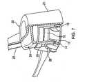
- Fig. 1depicts an access port fastening system according to one example.
- the access port 10includes a septum 11, which in practice is pierced by a needle to input fluid such as saline into the access port for use with, for example, a hydraulic operated gastric band.
- the access port 10includes a detachable housing 12 which surrounds the outer perimeter of the access port.
- the housing 12includes notches or openings 15.
- the notcheshouse fasteners 14.
- the notches or openings 15may take any form necessary to adequately house the fastener 14 while allowing movement of the fastener 14.
- At least three fasteners 14are present in order to minimize the possibility of movement or dislodgement of the device.
- the fasteners 14are attached to the ring 12 by a perpendicular segment engaged though a hole and thereby pivotally connected to the ring 12.
- the fasteners 14have a first position as shown in Figs. 1 and 3 and a second or secured position as shown in Figs. 2 and 4 .
- the fastenerrotates about an axis of the fastener.
- the notch 15accommodates this rotation and a small locking tab holds the fastener in position after rotation.
- the fasteners 14may be 2-legged staples.
- the staplesare rigid, such that they do not defonn during the rotation into the fascia of a patient. For such applications conventional metals are suitable.
- the staplesmay be shaped as a "U" or variations thereof.
- the fastener 14When in the second position, the fastener 14 is held rigidly in place by a locking tab 16, and fastener 14 may flex to allow the fastener to pass into the locked position.
- the formation of the locking tab 16may be such that upon movement of the fastener 14 from the first to the second position an audible click is heard by the surgeon to indicate that the fastener 14 is fully engaged by the locking tab 16. The click may also be tactile, allowing the surgeon to feel that the fastener is fully engaged by locking tab 16.
- an access port 10is secured within the housing 12 in the patient by the fasteners 14 which interface with the fascia of the patient. Essentially, the fascia or other bodily tissue is secured between the fasteners 14 and the housing 12 or device 10.
- the housing 12may contain pegs (not shown) which engage suture holes (not shown) which surround the perimeter of the device 10.
- Figs. 5-8depict the access port of Fig. 1 and its interaction with an access port delivery system 20.
- the access port delivery system 20may have a finger depression 25 which is used by the operator to help hold the access port and the delivery system in place and properly aligned.
- the delivery system 20comprises a port cover 21.
- the port cover 21houses a plunger 22, a slide pusher 24, and a slide assembly 26.
- the port covermay be formed in any shape necessary to substantially cover the access port 10.
- the plunger 22provides the operative means for the delivery system 20 and is connected to a firing means which will be described below.
- the firing meansUpon actuation of the firing means the plunger 22 moves in the direction of the access port 10. This movement causes the slide pusher 24 to be actuated.
- the slide pusher 24transfers the energy of the moving plunger 22 to the slide assembly 26.
- the slide assembly 26has a substantially round shape and encircles the access port 10. In other applications, the slide assembly may take a form suitable to the device and housing to be implanted.
- Alignment tabs 30assist the alignment of the slide assembly 26.
- the alignment tabs 30are attached to the port cover 21 and interact with the access port 10 to ensure proper alignment.
- the movement of the slide assembly 26causes beams 28 attached to the slide assembly 26 to act upon the fasteners 14.
- the imparting of force on the fasteners 14allows them to rotate in the ring holes (not shown) and to transcribe an arc defined substantially by the notch 15. This rotation coincides with a movement from the first to the second position discussed above.
- the fasteners 14reach the second position and are held in place by the locking tabs 16. In this position the access port 10 is rigidly held in place by the fasteners 14 and their interaction with the fascia or other tissue of the patient.
- Fig. 9shows an access port delivery system complete with a firing means 40.
- Fig. 10shows a cross sectional view of the firing means 40 in the starting or loaded position. In this position, the spring 42 is compressed, and a latch 44 that is connected to a rod 46 is secured by a rib 48 to prevent the compressed spring 42 from expanding.
- the firing meanshas a trigger 50 connected to a lever 52. As shown in Fig. 10 the spring 42 and rod 46 are in a housing 54.
- the lever 52upon application of a predetermined force to the trigger 50, the lever 52 acts on the housing 54.
- the housing 54pivots on a fulcrum (not shown), this pivoting action lifts the latch 44 above the end of the rib 48.
- the spring force of the compressed spring 42drives the plunger 22 in the direction of the access port and actuates the mechanism therearound as discussed above.
- the plunger travel, speed and impact forcecan be determined to meet the application needs.
- the plunger travelwas between .25 and .75 in, and can develop up to 50 1b. of force on the plunger, depending upon the spring used in the application.
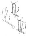
- Fig. 12shows a palm grip actuated firing mechanism 60.
- the palm gripis a very simple design requiring only a single moving part to move the plunger 22.
- a moving handle 61In a first position as shown in Fig, 13 , there is a moving handle 61, a stationary handle 62, a pivot point 64, and an actuating tip 66.
- the usersqueezes on the moving handle 61 forcing it in the direction of the stationary handle 62.
- This movementforces the actuating tip 66 which is connectively engaged with the moving handle 61 and the pivot point 64 in a direction opposite the direction of movement of the movable handle 61.
- a comparatively small force applied to the moving handle 61is amplified through the pivot point 64 and applied by the actuating tip 66 to the plunger 22.
- the plunger 22is moved by the actuating tip 66 in the direction of the access port 10 and actuates the mechanism therearound as discussed above.
- the force produced by the palm grip actuated deviceis limited only by the strength of the user, as tested the device was capable of producing in excess of 22.7 kg (50 lb.) of force with a plunger travel of 0.64 cm (25 in.).
- a geared mechanismcould be produced that could produce equal or greater force although require a greater travel distance for the moving handle 61.
- the force produced by the device shown in Figs. 12-14could also be altered as necessary by moving the pivot point 64 nearer the plunger 22 to produce more force, or away from the pivot point to produce less force.
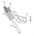
- the pistol grip firing means 70includes a trigger 72 having geared teeth 73 located on one end, a gear 74 which meshes with the geared teeth 73, a rack 75 driven by the gear 74, and a spring 76.
- the rackmay also include a means 78 for gripping the plunger 22.
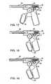
- Figs. 17-19The operative progression is shown in Figs. 17-19 .
- the triggeris extended and the spring is under little or no tension.
- the geared teeth 73are meshed with corresponding teeth of the gear 74 and with teeth on the rack 75.
- the plunger 22is in the extended position.
- the geared teeth 73actuate the gear 74 and in turn cause the rack 75 to compress the spring 76, as shown in Fig. 18 .
- the gear 74is free to spin.
- the stored energy in the spring 76forces the rack 75 to move toward the plunger 22.
- the free spinning gear 74allows the rack 75 to move, which in turn forces the plunger towards the access port 10 and actuates the mechanism therearound as discussed above.
- a lock(not shown), which after the spring 76 is compressed prevents the gear 74 from spinning. Then when desired the operator can release the lock, thereby allowing the spring 76 to expand as discussed above.
- the pistol grip firing means 70permits the plunger to travel approximately 4 in and can produce in excess of 22.7 kg (50 lb.) of force.
- One distinct advantage of this embodiment over, for example, the movable grip device discussed aboveis the instantaneous deployment having a very high impact speed.
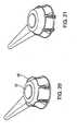
- NiTi fastenersare shown in a pre-deployment state.
- the fasteners 14are continuous and attached to the access port 10 through holes therein. In operation the fasteners 14 are depressed into the fascia of the patient to secure the access port.
- the NiTi fasteners 14have the unique ability to change their shape when heated, e.g. to body temperature.
- Fig. 21when the fasteners are deployed they can change shape to bend under the access port 10 and secure it in place.
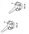
- Fig. 22the fasteners 14 are shown with straight legs 80 in a deployed state.
- Alternative configurationsinclude curved legs 81 as shown in Fig. 23 .
- the fasciacan be pinched between the fastener and the underside of the access port.
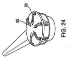
- Fig. 24A further alternative is shown in Fig. 24 where the tips of the fastener legs 81 are coated with a molded tip 82.
- the molded tipmay be formed in a shape that will assist in piercing the fascia of the patient. This eliminates the need to form the fastener 14 into a shape for piercing.
- the tips 82may be formed of a bio-absorbable material.
- the NiTi fastenercan be continuously formed in a ring 84.
- the use of the ring 84allows for the fasteners 14 to be formed with a continuous construction.
- the ends of the legs 80can be ground off to produce individual substantially U-shaped fasteners 14.
- the ring 84insures that the fasteners 14 can be inserted as a unit as discussed above, and the grinding of the legs ensures a sufficiently sharp point to pierce the fascia.
- the legscan be formed and positioned in the ring 84 so that after bending due to heating, the legs 80 face internally to the access port 10 or externally to the access port 10.
- FIG. 28shows a guide 90 formed with a plurality of individual fasteners 14.
- the fasteners 14are slidable in the guide 90 from a first to a second position.
- the fasteners 14are formed of a spring like material and shaped to attach to the access port 10.
- the fasteners 14are slid from a first position as shown in Fig. 28 to a second position as shown in Fig. 29 .
- the fasteners 14pierce the fascia and securely hold the access port 14 thereto.
- the fastenersmay have straight or curved legs.
- a further two-part fastening deviceincludes a pre-formed ring 100 ( Fig. 31 and Fig. 32 ).
- the ringincludes a first securing means 104 for attaching the ring 100 to the fascia.
- the ringalso includes a second securing means 102 for attaching an access port 10 to a secured ring 100.
- the ring 100is placed upon the fascia and then twisted to engage the fascia in the first securing means 104.
- the access port 10is then placed upon the ring 100 and engages the second securing means 102 via holes 106 in the access port.
- This designallows for positive attachment and re-installation repeatability without disengaging the pre-formed ring.
- Fig. 33 and Fig. 34depict yet another two-part fastening device comprising an applicator 112 and a ring 110 having NiTi fasteners 114.
- the ring 110is inserted into the applicator 112.
- the applicator 112is placed over the access port 10 with the fasteners 114 aligned with notches 115 and holes 106.
- the fasteners 114are forced through the holes 106 and engage the fascia of the patient upon which the access port 10 rests. Through the heating process, the fasteners 114 change shape and secure the access port to the fascia. After a predetermined time, the applicator can be removed.
- fastenersAs shown in Figs. 35-38 , a variety of designs can be used to secure an access port 10 to the fascia of a patient.
- the fastenersmay incorporate NiTi so that the fasteners change shape upon application of a predetermined amount of heat.
- These fasteners 14may be inserted singularly, or as part of a pre-formed ring as discussed above. When inserted singularly, the fasteners 14 may be straight rods or may have some pre-formed shape which may be heightened through the heating process.
- the fastener 14takes on a curly, pig-tail shape.
- Fig. 36the fastener takes on a substantially C-shaped appearance.
- FIG. 39Yet another example is shown in Fig. 39 .
- the fasteners 14are slidably installed in the access port 10. This may be accomplished by cold molding of the NiTi fastening system into the device, and allows positive attachment and repeatable re-positioning.
- an installation tool 120Through the use of an installation tool 120, the fasteners are forced through holes in the bottom of the access port 10 and engage the fascia.
- the installation tool 120could be part of a triggering device as disclosed herein.
- Fig. 40shows the fastener 14 in the engaged position.
- radial pivot fastenersare a simple delivery system, with direct drive.
- the associated delivery systemactuates the pivot for radial entry.
- the staplemay be stainless steel, titanium, Nitinol or ElgiloyTM, or other suitable materials including other metals or plastics.
- the molded pivot/lock-out systemmay be designed to snap into the existing suture holes on implantable devices.
- the simple staple shapeallows for easy manufacturability. Such a system is self-puncturing, i.e. no pre-puncturing of the bodily tissue, e.g. fascia, is necessary.
- the curved nature of the stapleallows the penetration into the bodily tissue as the staple advances to be predictable; and the pivoting nature of the curved staple generates an easy path through the tissue. Removal of the fastening system requires an extraction tool, and the staples will rotate out of the original entry path with only small resistance from ingrown surrounding tissue. However, the force required to remove the system is adequate to allow the staples to remain locked in position except during a removal procedure.
- Continuous wire forms of the fastener system contemplated hereininclude blunt tips, molded tips, and ground or chopped tips.
- Blunt tip continuous wire systemsas shown in Figures 20-23 may require pre-puncture for insertion of the blunt tipped wire.
- the fastener assemblymay be manufactured to require the locking feature to retain either the wire form or the overmolded ring.
- the simple wire formmay be made of stainless steel, titanium, ElgiloyTM, NiTi or other suitable materials. Removal of the fastener assembly may be done easily due to the blunt ends, which provide minimal tissue damage and trauma. Additionally, the blunt tip reduces the force necessary to remove the assembly.
- the continuous wire form assembly with molded tipsdoes not require pre-puncture of the bodily tissue, and these tips allow for easy entry into the bodily tissue. Further, the chopped or ground blunt end continuous wire form assembly, Figures 25-27 , also requires no pre-puncture of the bodily tissue, which also allows for easy entry into the tissue.
- the radial slide fastener assemblydepicted herein with flat fasteners ( Figures 28 and 29 ) and curved fasteners ( Figure 30 ), requires a larger entry site than the other fastener assemblies.
- the fastenerscreate a path through the bodily tissue that is simple and secure, with added retention in systems utilizing the curved fasteners. Removal of the systems is accomplished with an associated extraction tool that withdraws each fastener from their center position.
- the fastenersmay be manufactured such that removal may be accomplished by lifting the assembly upwards, at which time the fasteners bend to a straightened position, allowing for easy removal.
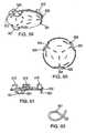
- Fig. 41depicts a helical coil fastener 201, which may optionally be utilized with a port that features a tubing connector extending from the center of the base.
- the corkscrew-type designis mounted to a separate disc 203 which snaps to the port at tabs 202, or alternatively may be mounted to the port itself, centered on the base plate.
- the disc or portis manually affixed to the tissue by rotation of the disc or port, which causes the coil to travel on a helical path through the tissue.
- the coilcan have a sharpened tip.
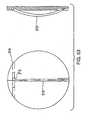
- FIG. 42depicts a flat spiral spring 204 that is deflected downward to begin its path through the tissue.
- the deflecting implement 205may be withdrawn following implantation, allowing the spring to compress during healing. Compression of the spring will reduce the profile of the implanted coil fastener and can reduce the likelihood of pain induction.
- Tabs 202are used for locking a port or other device into the fastener.
- FIGs 43-47 and Figure 55depict a horizontal coil implantation system.
- a metal coilis used horizontally to stitch the port to the tissue. It is well known that such coils can pierce and hold in tissues from their use as mesh tacks in minimally invasive hernia procedures. In this case, the coil travels parallel to the tissue surface instead of perpendicularly, as in the helical coil fasteners described above.
- a small deployment tool 206is envisioned to aid in driving the coil 208 through the tissue and the mating holes 207 in the base coil receptacle 209 (see Figs. 46 and 47 ). Such holes could be straight holes through a ridge on the bottom of the base (see Figs.
- curved holes molded into a flat-surfaced baseA top view of a base is shown in Fig. 43 . It is envisioned that the last hole would be blind, and that the end of the coil would be shaped in a crossbar that could slide over an incline and lock into place, such as into a slot. A variation would feature a path for the coil that curves around the port or base edge, facilitating tool access to the coil. This can also be accomplished by varying the flexibility of the coil. A tube can be added to the tool as a shroud in order to keep the rotating coil from picking up strings of tissue before it travels through the holes.
- FIGs. 48 to 62depict various example of a metal suture system.
- This method of port fixationinvolves the creation of one or multiple closed metal loops below the port base, by using the base itself as a means to close a loop formed by curved metal members (see, e.g. Figs. 48 and 52).
- Figure 48illustrates one closed loop, with a single curved metal member shown in its post-deployment position.
- Figure 49is a cutaway top view of one example showing the curved metal members 211 in their pre-deployment position.
- Figure 57depicts both a bottom and side view of one example showing the curved metal members forming a loop with the bottom of the base.
- Figure 51shows curved metal members, with the arrows indicating their deployment rotation.
- Fastening of a port in the above described mannermay be done both with one-piece and two-piece systems, whereby a two-piece system may have a ring 210 that attaches to the port or other device by snap-fitting with tabs 202 as shown in Fig. 50 .
- a deflection toolto separate the point of the metal member from contact with the base allowing the member tip to begin its path downward through the tissue. This can be a circular disc or the port itself. After the point has traveled some distance, the tool is withdrawn, permitting the curved member to then follow a path intersecting with the base.
- another embodimentincludes multiple members curved in two planes, such that rotation of the base affects the creating of multiple loops.
- a curved pin 212that is inserted through the base after it is in its intended tissue location, as seen in Figs. 53 and 54 .
- a pinby nature follows an arc through the tissue and can easily be directed back to the port base.
- Such a pincan be made to lock in place after full travel by adding a right angle bend 213 to the pin that snaps into a slot 214 on the base, or other such well-known means.
- a variation on this themeincludes an additional straight section on the end of the pin, parallel to the curved section.
- a lever arm 215is used to drive the curved section through the base and to the completion of its intended travel.
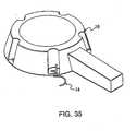
- a two-piece systemmay be used wherein the port attaches to a folding baseplate 218 with sharp, curved extensions 217 (see Fig. 56 ).
- the folded plateis placed on the tissue with the extensions pointed toward the tissue.
- the baseplateis unfolded (flattened) the extensions are driven 90 degrees in a rotary path (see Fig. 56 ).
- the portis then snapped to the baseplate, locking the extensions in position.
- the points of the extensionswould overlap those from the other half, semi-shielding the points.
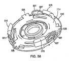
- Figs. 58-62illustrate a preferred rotating disc fastener system.
- the device to be implantedis secured to the tissue using a plurality of curved pins or hooks 501 ( Fig. 62 ), the tips of which rotate through an arc and are received back in or near the baseplate 510 at the end of their travel.
- a disc 520 within the baseplate 510rotates, thereby causing lever arms 525 to push against curved hooks 501, which in turn rotate about their fixed axis in the baseplate through an arc until the rotational travel of the disc stops.
- the tips of hooks 501are preferably received back in baseplate 10 to form a closed loop.
- the tipsmay form less than a closed loop.
- the rotating disc 520locks in place at the end of its travel to lock the hooks in place.
- One-way flexible locking tabs 527 that engage stops 515 or other locking meansmay be used to lock the hooks in place by preventing backward rotation of the disc.
- a deployment tool or delivery systemsuch as that described above with reference to Figures 5-19 may be used to fasten the device in place. The linear motion of the plunger 22 and slide pusher 24 is converted into rotational motion through a transmission using gearing or other well known means.
- Figures 63-72illustrate a preferred access port delivery system.
- lever 605is attached to handle 607 at hinge 621.
- Cable sheath 619is secured to handle 607 by securing pin 623.
- Cable sheath 619encloses cable 617 which is attached to lever 605 at the handle end of the device at cable stop 615. Cable sheath 619 allows the linear motion of cable 617.
- actuator lever 701 and port cover 631have curved lips 721 for gripping the baseplate of a disc fastener.
- actuator lever 701has groove 723 to allow the actuator lever to rotate around the baseplate with minimal contact, the only contact being from curved lip 721.
- Figure 66shows edge 713 of the actuator lever, which snaps into a matching groove of port cover 631 and secures the actuator lever but allows its rotational motion.
- Figure 65shows a top view of the actuator lever, and shows cable stop 705, where the deployment end of cable 617 is attached. Cable 617 runs through slot 707 and out through notch 709 and along groove 711. When the user of the deployment tool pulls lever 605 towards handle 607, cable 617 is pulled through the sheath towards handle 607.
- Figures 71 and 72show an embodiment of port cover 631 in greater detail. Attachment position 735 is the location where a cable sheath may attach to the port cover.
- both Figures 71 and 72show device passageway 737.
- Device passageway 737allows a port cover to be attached to a port or other device without interfering with any tubing or other instrumentation that may be running from the port or device.
- the passagewayis a square shape, however the passageway may be in a wide variety of shapes to accommodate a variety of devices.
- Figures 73 - 77depict a loading fixture for holding a combined port/disc fastener assembly.
- the port/disc fastener systemis snapped into the fixture, which protects the assembly, protects the user from accidental contact with the hooks, sharpened points, etc., used to fasten the assembly to tissue, prevents premature deployment of the assembly, and allows the user to load the port/disc fastener system into the deployment tool without actually touching the assembly.
- the deployment toolis snapped onto the assembly while it is still in the loading fixture.
- the loading fixtureSimilar to the device passageway of the port cover, the loading fixture has device passageway 739 to allow any tubing to hang freely from the device to be attached without any interference from the loading fixture.
- Figure 75shows how a device may be securely held in place by locking tabs 743 and/or pegs 741.
- Figure 76shows a port/disc fastener assembly being held securely by the loading fixture.
- Figure 77shows an exploded view of the disc fastener/loading fixture assembly without a port device attached.
- FIG. 58-62A brief description of the combined use of preferred embodiment of the disc fastener system shown in Figures 58-62 , the preferred embodiment of the deployment tool of Figures 63-68 and the loading fixture of Figures 73-77 is helpful in understanding the invention.
- the usergrasps the port delivery system at handle 607.
- the port/disc fastener assemblywould be held in the loading fixture, as shown in Figure 76 .
- the usermaneuvers the port cover 631 over the port/disc fastener assembly, and curved lips 721 of the actuator lever and port cover snap-fit with the baseplate 510, such that an audible and tactile click is heard and felt by the user.
- the userthen pulls the deployment tool from the loading fixture with the combined port/disc fastener attached and ready to be deployed.
Landscapes
- Health & Medical Sciences (AREA)
- Life Sciences & Earth Sciences (AREA)
- Surgery (AREA)
- Heart & Thoracic Surgery (AREA)
- Veterinary Medicine (AREA)
- General Health & Medical Sciences (AREA)
- Engineering & Computer Science (AREA)
- Public Health (AREA)
- Biomedical Technology (AREA)
- Animal Behavior & Ethology (AREA)
- Molecular Biology (AREA)
- Medical Informatics (AREA)
- Nuclear Medicine, Radiotherapy & Molecular Imaging (AREA)
- Pulmonology (AREA)
- Anesthesiology (AREA)
- Hematology (AREA)
- Surgical Instruments (AREA)
- Prostheses (AREA)
- Transplanting Machines (AREA)
Abstract
Description
- The present invention relates to the fields of implantable medical devices and surgical instruments and fasteners. The present invention encompasses the implants and the surgical fasteners used in surgical procedure.
- Surgical fasteners such as staples, clips, clamps, bands, tacks, or other wound or incision closure devices are commonly used in surgical procedures to allow a surgeon to fasten, secure and/or repair body tissue. Examples of surgical fasteners are given in
U.S. Pat. Nos. 4,994,073 or4,950,284 or4,934,364 and4,932,960 . - Surgical fasteners have been used in surgical procedures to eliminate the need for suturing, which is both time consuming and inconvenient. In these applications the surgeon often uses a fastener implanting device loaded with one or more surgical fasteners to accomplish in a few seconds what would have taken many minutes to perform by suturing. This reduction in operating time reduces blood loss and trauma to the patient.
- Typically, such fastening systems have been used mainly for the closure of incisions or wounds, or to fasten tissues together. A surgical fastening system that could be used with a number of types of implantable devices would be beneficial for surgeons. Currently, surgical devices that incorporate fastening systems often use extremely specialized systems that may be unnecessarily complicated and are unsuitable for adaptation to other applications. As a result, the majority of implantable devices are secured with sutures. For example, when inserting a gastric band and the associated access port, the port is sutured into place with 4 to 5 sutures against the rectus muscle sheath Such placement of the sutures is often challenging because the ports are placed below several centimeters of fat, and suturing the port often takes as long as placing the band itself. An improved fastening system would allow easy, one-step attachment with security equivalent to the sutured device.
- The present invention overcomes such problems in the art.
US5540648 discloses a port implant which has a plurality of rotatable fasteners in a pre-deployment position, the rotation of the fasteners allowing fastening of the implant to the patient. The two-part form of claim 1 is based on this document. This provides quick and easy fastening of a device to the patient, but the fasteners must be individually rotated, and thus the problem remains of allowing simultaneous deployment of multiple fasteners without excessive complexity of the device.- The present invention encompasses surgical fastening systems wherein an implantable device may have a housing fitted over the device, wherein the housing contains a plurality of fasteners in pre-deployment position. The invention is defined in the appended claim 1. Preferable features are defined in the dependent claims.
- The above objects and advantages of the present invention will be more fully understood by reference to the following description and annexed drawings, in which:
Figure 1 is an elevation view of a radial pivot fastener with staples in pre-deployment position;Figure 2 is an elevation view of the radial pivot fastener ofFigure 1 with staples in deployed position;Figure 3 is a detail elevation view of the radial pivot fastener ofFigure 1 with staples in pre-deployment position;Figure 4 is a detail elevation view of the radial pivot fastener ofFigure 2 with staples in deployment position;Figure 5 is an elevation view of a delivery system;Figure 6 is a cutaway view of the delivery system shown inFigure 5 and a port fastener;Figure 7 is a detail cutaway elevation view of the distal end of the delivery system ofFigure 6 and a port fastener in pre-deployment position;Figure 8 is a detail cutaway elevation view of the distal end of the delivery system ofFigure 6 and a port fastener in deployment position;Figure 9 is an elevation view of a pencil grip handle configuration for a delivery system;Figure 10 is a detail cutaway elevation view of the handle of the delivery system ofFigure 9 shown in a starting position;Figure 11 is a detail cutaway elevation view of the handle of the delivery system ofFigure 9 shown in a fired position;Figure 12 is an elevation view of a pistol grip handle configuration for a delivery system;Figure 13 is a detail elevation view of the handle of the delivery system ofFigure 12 shown in a starting position;Figure 14 is a detail elevation view of the handle of the delivery system ofFigure 12 shown in a fired position;Figure 15 is an elevation view of another pistol grip handle configuration for a delivery system;Figure 16 is a detail view of the gear train mechanism of the delivery system ofFigure 15 ;Figure 17 is a detail cutaway elevation view of the delivery system ofFigure 15 shown in a starting position;Figure 18 is a detail cutaway elevation view of the delivery system ofFigure 15 shown in a full spring recoil position;Figure 19 is a detail cutaway elevation view of the delivery system ofFigure 15 shown in a fired position;Figure 20 is an elevation view of a continuous NiTi wire form fastener in pre-deployment position;Figure 21 is an elevation view of the continuous NiTi wire form fastener ofFigure 20 in post-deployment position;Figure 22 is a bottom elevation view of a straight leg, blunt tip continuous wire form fastener;Figure 23 is a bottom elevation view of a curved leg, blunt tip continuous wire form fastener;Figure 24 is a bottom elevation view of a molded tip continuous wire form fastener;Figure 25 is an elevation view of a continuous NiTi wire form fastener with grounds tips in post-deployment external position;Figure 26 is an elevation view of a continuous NiTi wire form fastener with grounds tips in post-deployment internal position;Figure 27 is a bottom elevation view of the continuous NiTi wire form fastener with grounds tips ofFigure 26 in post-deployment internal position;Figure 28 is an elevation view of a radial slide fastener with straight legs and a staple guide;Figure 29 is an elevation view of the radial slide fastener ofFigure 28; Figure 30 is an elevation view of a radial slide fastener with curved legs;Figure 31 is an elevation view of a two-part fastening system before installation;Figure 32 is an elevation view of the two-part fastening system ofFigure 31 after installation;Figure 33 is an elevation view of another two-part fastening system before installation;Figure 34 is an elevation view of the two-part fastening system ofFigure 33 after installation;Figure 35 is an elevation view of a stand-alone fastener incorporated into a device;Figure 36 is an elevation view of another stand-alone fastener incorporated into a device;Figure 37 is an elevation view of another stand-alone fastener incorporated into a device;Figure 38 is an elevation view of another stand-alone fastener incorporated into a device;Figure 39 is an elevation view of another stand-alone fastener incorporated into an injection port in a pre-installation position;Figure 40 is an elevation view of the stand-alone fastener ofFigure 39 in a post-installation position;Figure 41 is an elevation view of a helical coil fastener;Figure 42 is an elevation view of another helical coil fastener;Figure 43 is a top view of a horizontal coil fastening system base;Figure 44 is a side view of the horizontal coil fastening system base ofFigure 43; Figure 45 is a bottom view of the horizontal coil fastening system base ofFigure 43; Figure 46 is an elevation view of a driver tool of a fastening system for the horizontal coil fastening system ofFigure 43 ;Figure 47 is a detail view of the horizontal coil fastening system base ofFigure 43 .Figure 48 is a side view of a closed metal loop fastening system incorporated into a device;Figure 49 is a top view of device incorporating the closed metal loop fastening system ofFigure 48 ;Figure 50 is a side view of a two-part snap fit fastening system.Figure 51 is an elevation view of a another closed metal loop system using curved pins or hooks;Figure 52 is a side view of the closed metal loop system using the curved pins or hooks ofFigure 51 incorporated into a device;Figure 53 shows top and side views of a curved pin fastening system incorporated into a device;Figure 54 shows top and side views of another curved pin fastening system incorporated into a device;Figure 55 shows bottom and side view of a spring screw fastening system;Figure 56 shows side view of a folding baseplate with curved fasteners in its open and closed positions;Figure 57 shows top and side views of rotating hook fasteners incorporated into a device;Figure 58 is a top elevation view of a rotating disc fastening system with fasteners in pre-deployment position;Figure 59 is a bottom elevation view of the rotating disc fastening system ofFigure 58 with fastener in post-deployment position;Figure 60 is a bottom view of the rotating disc fastening system ofFigure 58 with fasteners in post-deployment position;Figure 61 is a side view of the rotating disc fastening system ofFigure 58 with fasteners partially deployed; andFigure 62 is an elevation view of the curved fastener of the rotating disc fastening system ofFigure 58 showing the axis of rotation.Figure 63 is cutaway side view of a delivery system.Figure 64 is a side elevation view of a delivery system.Figure 65 is a top view of the actuator lever of the delivery system ofFigures 63 and 64 .Figure 66 is a side view of the actuator lever of the delivery system ofFigures 63 and 64 .Figure 67 is a bottom view of the actuator lever of the delivery system ofFigures 63 and 64 .Figure 68 is a side elevation view of the actuator lever of the delivery system ofFigures 63 and 64 .Figure 69 is a partially exploded and cutaway view of the port cover of the delivery system ofFigures 63 and 64 .Figure 70 is a partial cutaway view of the port cover of the delivery system ofFigures 63 and 64 .Figure 71 is a back view of the port cover of the delivery system ofFigures 63 and 64 .Figure 72 is an elevated side view of the port cover of the delivery system ofFigures 63 and 64 .Figure 73 is an elevated bottom view of a loading fixture.Figure 74 is a bottom view of a loading fixture.Figure 75 is an elevated view of a loading fixture.Figure 76 is an elevated view of a disc fastener/port/loading fixture assembly.Figure 77 is an exploded view of a disc fastener/loading fixture assembly.- The present invention encompasses surgical fastening systems wherein an implantable device may have a detachable housing fitted over the device, wherein the housing contains a plurality of fasteners in pre-deployment position.
- The detachable housing and fasteners may be made of various materials known in the art for the manufacture of surgical fasteners and implants. The fasteners may be made of metal, polymer, or other suitable materials. The detachable housing may be made of metal, polymer, ceramic, or composites; for instance polysulfone, acetyl copolymers, titanium, elastomers and stainless steel are commonly used.
- These materials must be biocompatible, i.e., they do not adversely affect the surrounding living environment, and conversely, their performance is not adversely affected by the surrounding living environment. The materials may be inert non-absorbable or biodegradable. Inert materials may be fairly indestructible and maintain their form and function for extended periods of time.
- Metals and metal alloys, and particularly titanium and titanium alloys, are used for a great variety of implantable articles for medical applications. All implantable articles suffer from some degree of bio-incompatibility, which may be manifested as tissue inflammation, necrosis, hyperplasia, mutagenicity, toxicity, and other reactions, such as attack by giant cells, leukocytes and macrophages. While titanium and its alloys are generally considered inert when implanted, some biological and biochemical interactions still may occur, and others have found it desirable to provide various coatings on the surface of titanium and titanium alloy implants for certain purposes. The same holds true for many other metals and metal alloys. Thus, the present invention encompasses the use of such coatings on the surface of the fasteners, the removable housing, or the device.
- Some of the coatings that may be used in materials to be implanted (whether made of titanium or other materials) include biological agents (such as genetic material or cellular material) or chemical agents (such as anti-proliferation reagents or cell-growth factors) to reduce problems associated with hyperplasia or inflammation. These agents may be mixed with binders such as elastomers or bio-resorbable polymers to the surface of a metal or polymer object.
- The fasteners contemplated herein, including staples, are often constructed of wire and thus have a relatively large surface area for their size. Accordingly, methods that allow the addition of biological and biochemical agents to the surface of the implant may be advantageous in minimizing the adverse reactions of body tissues with the implant. These may include coatings applied to stainless steel and titanium alloys (e.g., NiTi alloys) to retard tissue reactions. Such coatings have been based upon stable bio-compatible polymers (such as styrene-isobutylene-styrene (SIBS)) and bio-resorbable polymers, such as polyglycolic acid. In the work known to date, the active chemical or biological agent is mixed with the polymeric coating material, and the agent then elutes from the coating once the implant is placed in the body.
- It is also contemplated by the present invention that the fasteners may be made of shape memory alloy (SMA). The driving force for making metal medical devices from shape memory alloys lies in their great resistance to permanent deformation as compared to conventional alloys employed in this application. Alloys used in various medical instruments have relied on stainless steel, high nickel alloys such as Elgiloy™ and titanium based alloys, all of which can be given quite high yield strength through work hardening. Normal metals, even with very high yield strength, cannot sustain strains much greater than 0.2% without suffering a permanent set. Once a bend or kink has been sustained in a device fabricated from one of the above conventional alloys it is virtually impossible to remove. The unusual property of pseudoelasticity exhibited by shape memory alloys such as Au-Cd, Cu-Zn-Al, Ni-Ti and many others makes possible the complete "elastic" recovery of strains as great as 10%. Due to its high recoverable strain and its excellent resistance to corrosion, the shape memory alloy of preference for medical components has been within the Ni-Ti family of alloys.
- Shape memory alloys belong to a class which exhibit thermoelastic martensite transformation. The term martensite refers to the crystalline phase which is produced in steels when quenched from a high temperature. The phase which exists at the elevated temperature is referred to as austenite; these terms have been carried over to describe the transformations which occur in shape memory alloys. When a steel has been quenched from the austenitic temperature to martensite, to again form austenite requires heating the structure to quite high temperatures, usually in excess of 760°C (1400°F).
- By contrast, the thermoelastic shape memory alloys can change from martensite to austenite and back again on heating and cooling over a very small temperature range, typically from - 8 to 13 °C (18 to 55°F). The transformation of a shape memory alloy is usually described by a hysteresis curve in which it is shown that on cooling from the austenitic phase, often called the parent phase, martensite starts to form at a temperature designated as MS and upon reaching the lower temperature, MF, the alloy is completely martensitic. Upon heating from below the MF temperature, the martensite starts to revert to the austenitic structure at As, and when the temperature designated as AF is reached, the alloy is completely austenitic. These two phases or crystalline structures have very different mechanical properties: the Young's Modulus of austenite is ~ 82.7 x 10⁶ kPa (~12x106) psi, while that for martensite is ~ 27.6 x 10⁶ kPa (~4x10⁶) psi; and the yield strength, which depends on the amount of cold work the alloy is given, ranges from (193 - 659) x 106 Pa (28 to 100 ksi) for austenite and from (69 - 138) x 106 Pa (10 to 20 ksi) for martensite.
- The unique feature of shape memory alloys is their ability to recover deformation. When a shape memory alloy specimen, in its martensitic form is subjected to stress, the strain is accommodated by the growth and shrinkage of individual martensite variants rather than by the mechanisms which prevail in conventional alloys: slip, grain boundary sliding and dislocation motion. When deformed martensite is heated to the austenite finish temperature AF, the part reverts to its original undeformed state. Thus, for medical implant uses, it is possible to develop a design where the device is stored below body temperature in its unformed shape, and upon insertion into the body, the temperature of the device raises to that of the body, at which point the device reverts to the austenitic structure. In the instant application, the fasteners may be optionally made of an SMA such as NiTi.
- It is within the scope of the present invention that such fastening systems as herein described are able to be fastened into bodily tissue in less time than would be required to suture the device into place. In the instance described here (the placement of an access port for a gastric band), the placement and fixation of the fastening system should take no more than five minutes. Additionally, the fixation system is able to be entirely unfastened and removed from the tissue in order to facilitate repositioning of the device, or to remove the implanted device entirely. Such implantation and extraction will not cause increased trauma to the patient, and the fixation system will not cause more adhesions than the traditional suturing method. The average surgeon or other health professional is reliably and consistently able to perform fixation and extraction of the fastening system.
- Additionally, during the manufacture of such fixation systems described herein, the size of the fasteners determines the depth into the bodily tissue into which the fasteners will deploy. In the instant case, fixation of an access port should occur at a depth below the device not to exceed 3mm. Also, in such a use, the bodily tissue into which the fasteners are deployed is the fascia. However, it is within the scope of the invention that the bodily tissue to which the device is attached will vary depending on the specific device. Additionally, the attachment of the fastening system into tissue will not cause tissue damage during placement or during body motion; for example, an access port for a gastric band is often attached directly over the rectus abdominis. Further, the fixation of the device is of equivalent or greater strength to sutures and resists becoming dislodged or disconnected in order to accommodate a long-term implant.
- The invention as described herein may be used with any type of implantable access ports. For ease of explanation, an example will now be described as depicted in
Figures 1-40 , wherein the example is shown used in conjunction with an access port. One of skill in the art will recognize that the present invention may be used with other types of implantable devices, and that the examples may take other forms analogous to those depicted herein. - Additionally, in the accompanying figures, the housing is shaped as a ring, and may accordingly be described as such. However, one of skill in the art will recognize that the shape of the housing is dependent on that of the device, such that the present example is not limited to devices in which the housing would be circular.
Fig. 1 depicts an access port fastening system according to one example. Theaccess port 10 includes aseptum 11, which in practice is pierced by a needle to input fluid such as saline into the access port for use with, for example, a hydraulic operated gastric band.- The
access port 10 includes adetachable housing 12 which surrounds the outer perimeter of the access port. Thehousing 12 includes notches oropenings 15. The notches housefasteners 14. The notches oropenings 15 may take any form necessary to adequately house thefastener 14 while allowing movement of thefastener 14. At least threefasteners 14 are present in order to minimize the possibility of movement or dislodgement of the device. As shown inFigs. 1-4 , thefasteners 14 are attached to thering 12 by a perpendicular segment engaged though a hole and thereby pivotally connected to thering 12. Thefasteners 14 have a first position as shown inFigs. 1 and3 and a second or secured position as shown inFigs. 2 and4 . To move from the first to the second position, the fastener rotates about an axis of the fastener. Thenotch 15 accommodates this rotation and a small locking tab holds the fastener in position after rotation. In one example, thefasteners 14 may be 2-legged staples. In another embodiment, the staples are rigid, such that they do not defonn during the rotation into the fascia of a patient. For such applications conventional metals are suitable. Furthermore, the staples may be shaped as a "U" or variations thereof. - When in the second position, the
fastener 14 is held rigidly in place by alocking tab 16, andfastener 14 may flex to allow the fastener to pass into the locked position. The formation of thelocking tab 16 may be such that upon movement of thefastener 14 from the first to the second position an audible click is heard by the surgeon to indicate that thefastener 14 is fully engaged by the lockingtab 16. The click may also be tactile, allowing the surgeon to feel that the fastener is fully engaged by lockingtab 16. When in the second position anaccess port 10 is secured within thehousing 12 in the patient by thefasteners 14 which interface with the fascia of the patient. Essentially, the fascia or other bodily tissue is secured between thefasteners 14 and thehousing 12 ordevice 10. Furthermore, thehousing 12 may contain pegs (not shown) which engage suture holes (not shown) which surround the perimeter of thedevice 10. Figs. 5-8 depict the access port ofFig. 1 and its interaction with an accessport delivery system 20. As shown inFig. 5 , the accessport delivery system 20 may have afinger depression 25 which is used by the operator to help hold the access port and the delivery system in place and properly aligned.- The
delivery system 20 comprises aport cover 21. The port cover 21 houses aplunger 22, aslide pusher 24, and aslide assembly 26. The port cover may be formed in any shape necessary to substantially cover theaccess port 10. - The
plunger 22 provides the operative means for thedelivery system 20 and is connected to a firing means which will be described below. Upon actuation of the firing means theplunger 22 moves in the direction of theaccess port 10. This movement causes theslide pusher 24 to be actuated. Theslide pusher 24 transfers the energy of the movingplunger 22 to theslide assembly 26. Theslide assembly 26 has a substantially round shape and encircles theaccess port 10. In other applications, the slide assembly may take a form suitable to the device and housing to be implanted. Upon actuation, theslide assembly 26 is forced in the direction of theaccess port 10.Alignment tabs 30 assist the alignment of theslide assembly 26. Thealignment tabs 30 are attached to theport cover 21 and interact with theaccess port 10 to ensure proper alignment. The movement of theslide assembly 26 causes beams 28 attached to theslide assembly 26 to act upon thefasteners 14. The imparting of force on thefasteners 14 allows them to rotate in the ring holes (not shown) and to transcribe an arc defined substantially by thenotch 15. This rotation coincides with a movement from the first to the second position discussed above. As thebeams 28 continue to be moved towards theaccess port 10, thefasteners 14 reach the second position and are held in place by the lockingtabs 16. In this position theaccess port 10 is rigidly held in place by thefasteners 14 and their interaction with the fascia or other tissue of the patient. Fig. 9 shows an access port delivery system complete with a firing means 40.Fig. 10 shows a cross sectional view of the firing means 40 in the starting or loaded position. In this position, thespring 42 is compressed, and alatch 44 that is connected to arod 46 is secured by arib 48 to prevent thecompressed spring 42 from expanding. The firing means has atrigger 50 connected to alever 52. As shown inFig. 10 thespring 42 androd 46 are in ahousing 54.- As shown in
Fig. 11 , upon application of a predetermined force to thetrigger 50, thelever 52 acts on thehousing 54. Thehousing 54 pivots on a fulcrum (not shown), this pivoting action lifts thelatch 44 above the end of therib 48. Upon lifting, the spring force of thecompressed spring 42 drives theplunger 22 in the direction of the access port and actuates the mechanism therearound as discussed above. In such a configuration the plunger travel, speed and impact force can be determined to meet the application needs. As tested, the plunger travel was between .25 and .75 in, and can develop up to 50 1b. of force on the plunger, depending upon the spring used in the application. - An alternative to the spring driven mechanism is shown in
Fig. 12. Fig. 12 shows a palm grip actuated firingmechanism 60. The palm grip is a very simple design requiring only a single moving part to move theplunger 22. In a first position as shown inFig, 13 , there is a movinghandle 61, astationary handle 62, apivot point 64, and anactuating tip 66. - In operation the user squeezes on the moving
handle 61 forcing it in the direction of thestationary handle 62. This movement forces theactuating tip 66 which is connectively engaged with the movinghandle 61 and thepivot point 64 in a direction opposite the direction of movement of themovable handle 61. Through the use of the simple lever action, a comparatively small force applied to the movinghandle 61 is amplified through thepivot point 64 and applied by theactuating tip 66 to theplunger 22. Theplunger 22 is moved by theactuating tip 66 in the direction of theaccess port 10 and actuates the mechanism therearound as discussed above. The force produced by the palm grip actuated device is limited only by the strength of the user, as tested the device was capable of producing in excess of 22.7 kg (50 lb.) of force with a plunger travel of 0.64 cm (25 in.). Alternatively, a geared mechanism could be produced that could produce equal or greater force although require a greater travel distance for the movinghandle 61. The force produced by the device shown inFigs. 12-14 could also be altered as necessary by moving thepivot point 64 nearer theplunger 22 to produce more force, or away from the pivot point to produce less force. - Yet another alternative firing means is shown in
Figs. 15-19 . The pistol grip firing means 70 includes atrigger 72 having gearedteeth 73 located on one end, agear 74 which meshes with the gearedteeth 73, arack 75 driven by thegear 74, and aspring 76. The rack may also include ameans 78 for gripping theplunger 22. - The operative progression is shown in
Figs. 17-19 . InFig. 17 , the trigger is extended and the spring is under little or no tension. The gearedteeth 73 are meshed with corresponding teeth of thegear 74 and with teeth on therack 75. Theplunger 22 is in the extended position. When thetrigger 72 is depressed, the gearedteeth 73 actuate thegear 74 and in turn cause therack 75 to compress thespring 76, as shown inFig. 18 . At a predetermined distance the gearedteeth 73 no longer engage thegear 74. At this point thegear 74 is free to spin. The stored energy in thespring 76 forces therack 75 to move toward theplunger 22. Thefree spinning gear 74 allows therack 75 to move, which in turn forces the plunger towards theaccess port 10 and actuates the mechanism therearound as discussed above. - Another feature which may be incorporated into the pistol grip firing means 70 is a lock (not shown), which after the
spring 76 is compressed prevents thegear 74 from spinning. Then when desired the operator can release the lock, thereby allowing thespring 76 to expand as discussed above. - As tested, the pistol grip firing means 70 permits the plunger to travel approximately 4 in and can produce in excess of 22.7 kg (50 lb.) of force. One distinct advantage of this embodiment over, for example, the movable grip device discussed above is the instantaneous deployment having a very high impact speed.
- In
Fig. 20 a further example is shown. The use of NiTi or SMA alloy materials is well known in the medical arts as discussed above. As shown inFig. 20 NiTi fasteners are shown in a pre-deployment state. Thefasteners 14 are continuous and attached to theaccess port 10 through holes therein. In operation thefasteners 14 are depressed into the fascia of the patient to secure the access port. TheNiTi fasteners 14 have the unique ability to change their shape when heated, e.g. to body temperature. As shown inFig. 21 , when the fasteners are deployed they can change shape to bend under theaccess port 10 and secure it in place. - In
Fig. 22 thefasteners 14 are shown withstraight legs 80 in a deployed state. Alternative configurations includecurved legs 81 as shown inFig. 23 . Using thecurved legs 81, the fascia can be pinched between the fastener and the underside of the access port. A further alternative is shown inFig. 24 where the tips of thefastener legs 81 are coated with a moldedtip 82. The molded tip may be formed in a shape that will assist in piercing the fascia of the patient. This eliminates the need to form thefastener 14 into a shape for piercing. Additionally, thetips 82 may be formed of a bio-absorbable material. - In another example, the NiTi fastener can be continuously formed in a
ring 84. The use of thering 84 allows for thefasteners 14 to be formed with a continuous construction. After thering 84 with thefasteners 14 is formed, the ends of thelegs 80 can be ground off to produce individual substantiallyU-shaped fasteners 14. Thering 84 insures that thefasteners 14 can be inserted as a unit as discussed above, and the grinding of the legs ensures a sufficiently sharp point to pierce the fascia. As shown inFigs. 25 and 27 , the legs can be formed and positioned in thering 84 so that after bending due to heating, thelegs 80 face internally to theaccess port 10 or externally to theaccess port 10. - Yet another example is a two-part fastening system as shown in
Figs. 28-34 .Fig. 28 shows aguide 90 formed with a plurality ofindividual fasteners 14. Thefasteners 14 are slidable in theguide 90 from a first to a second position. In operation theguide 90 is placed over theaccess port 10 and aligned withnotches 15. Thefasteners 14 are formed of a spring like material and shaped to attach to theaccess port 10. Thefasteners 14 are slid from a first position as shown inFig. 28 to a second position as shown inFig. 29 . Thefasteners 14 pierce the fascia and securely hold theaccess port 14 thereto. As previously described, the fasteners may have straight or curved legs. After the sliding of all of the fasteners from theguide 90 onto theaccess port 10, the guide may be removed if it is not part of the final implanted device. Alternatively, theguide 90 may also be a permanent part of the implantable device. - A further two-part fastening device includes a pre-formed ring 100 (
Fig. 31 and Fig. 32 ). The ring includes a first securing means 104 for attaching thering 100 to the fascia. The ring also includes a second securing means 102 for attaching anaccess port 10 to asecured ring 100. In operation, thering 100 is placed upon the fascia and then twisted to engage the fascia in the first securing means 104. Theaccess port 10 is then placed upon thering 100 and engages the second securing means 102 viaholes 106 in the access port. This design allows for positive attachment and re-installation repeatability without disengaging the pre-formed ring. Fig. 33 and Fig. 34 depict yet another two-part fastening device comprising anapplicator 112 and aring 110 havingNiTi fasteners 114. In practice, thering 110 is inserted into theapplicator 112. Theapplicator 112 is placed over theaccess port 10 with thefasteners 114 aligned withnotches 115 and holes 106. Thefasteners 114 are forced through theholes 106 and engage the fascia of the patient upon which theaccess port 10 rests. Through the heating process, thefasteners 114 change shape and secure the access port to the fascia. After a predetermined time, the applicator can be removed.- Another example regards stand alone fasteners. As shown in
Figs. 35-38 , a variety of designs can be used to secure anaccess port 10 to the fascia of a patient. The fasteners may incorporate NiTi so that the fasteners change shape upon application of a predetermined amount of heat. Thesefasteners 14 may be inserted singularly, or as part of a pre-formed ring as discussed above. When inserted singularly, thefasteners 14 may be straight rods or may have some pre-formed shape which may be heightened through the heating process. InFig. 35 , thefastener 14 takes on a curly, pig-tail shape. InFig. 36 the fastener takes on a substantially C-shaped appearance.Figs. 37 and38 useU-shaped fasteners 14, the ends of which bend, linearly when heated to form an omega shape as shown inFig. 37 , or perpendicularly to the shape as shown inFig. 38 . These shapes can be chosen as desired for a specific application. - Yet another example is shown in
Fig. 39 . InFig. 39 thefasteners 14 are slidably installed in theaccess port 10. This may be accomplished by cold molding of the NiTi fastening system into the device, and allows positive attachment and repeatable re-positioning. Through the use of aninstallation tool 120, the fasteners are forced through holes in the bottom of theaccess port 10 and engage the fascia. By installing the fasteners as an integral part of theaccess port 10, no ring or housing is needed as discussed above for housing the fasteners. Theinstallation tool 120 could be part of a triggering device as disclosed herein.Fig. 40 shows thefastener 14 in the engaged position. - As described above and shown in
Figures 1-8 , radial pivot fasteners are a simple delivery system, with direct drive. The associated delivery system actuates the pivot for radial entry. The staple may be stainless steel, titanium, Nitinol or Elgiloy™, or other suitable materials including other metals or plastics. The molded pivot/lock-out system may be designed to snap into the existing suture holes on implantable devices. Additionally, the simple staple shape allows for easy manufacturability. Such a system is self-puncturing, i.e. no pre-puncturing of the bodily tissue, e.g. fascia, is necessary. The curved nature of the staple allows the penetration into the bodily tissue as the staple advances to be predictable; and the pivoting nature of the curved staple generates an easy path through the tissue. Removal of the fastening system requires an extraction tool, and the staples will rotate out of the original entry path with only small resistance from ingrown surrounding tissue. However, the force required to remove the system is adequate to allow the staples to remain locked in position except during a removal procedure. - Continuous wire forms of the fastener system contemplated herein include blunt tips, molded tips, and ground or chopped tips. Blunt tip continuous wire systems, as shown in
Figures 20-23 may require pre-puncture for insertion of the blunt tipped wire. The fastener assembly may be manufactured to require the locking feature to retain either the wire form or the overmolded ring. The simple wire form may be made of stainless steel, titanium, Elgiloy™, NiTi or other suitable materials. Removal of the fastener assembly may be done easily due to the blunt ends, which provide minimal tissue damage and trauma. Additionally, the blunt tip reduces the force necessary to remove the assembly. The continuous wire form assembly with molded tips, shown inFigures 20 and24 , does not require pre-puncture of the bodily tissue, and these tips allow for easy entry into the bodily tissue. Further, the chopped or ground blunt end continuous wire form assembly,Figures 25-27 , also requires no pre-puncture of the bodily tissue, which also allows for easy entry into the tissue. - The radial slide fastener assembly, depicted herein with flat fasteners (
Figures 28 and 29 ) and curved fasteners (Figure 30 ), requires a larger entry site than the other fastener assemblies. The fasteners create a path through the bodily tissue that is simple and secure, with added retention in systems utilizing the curved fasteners. Removal of the systems is accomplished with an associated extraction tool that withdraws each fastener from their center position. Alternatively, the fasteners may be manufactured such that removal may be accomplished by lifting the assembly upwards, at which time the fasteners bend to a straightened position, allowing for easy removal. Fig. 41 depicts ahelical coil fastener 201, which may optionally be utilized with a port that features a tubing connector extending from the center of the base. The corkscrew-type design is mounted to aseparate disc 203 which snaps to the port attabs 202, or alternatively may be mounted to the port itself, centered on the base plate. The disc or port is manually affixed to the tissue by rotation of the disc or port, which causes the coil to travel on a helical path through the tissue. In one embodiment, the coil can have a sharpened tip.- A variation of the helical coil fastener is depicted in
Fig. 42. Fig. 42 depicts aflat spiral spring 204 that is deflected downward to begin its path through the tissue. The deflecting implement 205 may be withdrawn following implantation, allowing the spring to compress during healing. Compression of the spring will reduce the profile of the implanted coil fastener and can reduce the likelihood of pain induction.Tabs 202 are used for locking a port or other device into the fastener. Figures 43-47 andFigure 55 depict a horizontal coil implantation system. In the horizontal coil system, a metal coil is used horizontally to stitch the port to the tissue. It is well known that such coils can pierce and hold in tissues from their use as mesh tacks in minimally invasive hernia procedures. In this case, the coil travels parallel to the tissue surface instead of perpendicularly, as in the helical coil fasteners described above. Asmall deployment tool 206 is envisioned to aid in driving thecoil 208 through the tissue and the mating holes 207 in the base coil receptacle 209 (seeFigs. 46 and 47 ). Such holes could be straight holes through a ridge on the bottom of the base (seeFigs. 44, 45 and 47 ), or curved holes molded into a flat-surfaced base. A top view of a base is shown inFig. 43 . It is envisioned that the last hole would be blind, and that the end of the coil would be shaped in a crossbar that could slide over an incline and lock into place, such as into a slot. A variation would feature a path for the coil that curves around the port or base edge, facilitating tool access to the coil. This can also be accomplished by varying the flexibility of the coil. A tube can be added to the tool as a shroud in order to keep the rotating coil from picking up strings of tissue before it travels through the holes.Figs. 48 to 62 depict various example of a metal suture system. This method of port fixation involves the creation of one or multiple closed metal loops below the port base, by using the base itself as a means to close a loop formed by curved metal members (see, e.g.Figs. 48 and 52). Figure 48 illustrates one closed loop, with a single curved metal member shown in its post-deployment position.Figure 49 is a cutaway top view of one example showing thecurved metal members 211 in their pre-deployment position.Figure 57 depicts both a bottom and side view of one example showing the curved metal members forming a loop with the bottom of the base.Figure 51 shows curved metal members, with the arrows indicating their deployment rotation. Fastening of a port in the above described manner may be done both with one-piece and two-piece systems, whereby a two-piece system may have aring 210 that attaches to the port or other device by snap-fitting withtabs 202 as shown inFig. 50 . One embodiment includes a deflection tool to separate the point of the metal member from contact with the base allowing the member tip to begin its path downward through the tissue. This can be a circular disc or the port itself. After the point has traveled some distance, the tool is withdrawn, permitting the curved member to then follow a path intersecting with the base. Likewise, another embodiment includes multiple members curved in two planes, such that rotation of the base affects the creating of multiple loops.- An alternate method to achieve such a loop is with a
curved pin 212 that is inserted through the base after it is in its intended tissue location, as seen inFigs. 53 and54 . Such a pin by nature follows an arc through the tissue and can easily be directed back to the port base. Such a pin can be made to lock in place after full travel by adding aright angle bend 213 to the pin that snaps into aslot 214 on the base, or other such well-known means. A variation on this theme includes an additional straight section on the end of the pin, parallel to the curved section. Alever arm 215 is used to drive the curved section through the base and to the completion of its intended travel. - In yet another example, a two-piece system may be used wherein the port attaches to a folding baseplate 218 with sharp, curved extensions 217 (see
Fig. 56 ). The folded plate is placed on the tissue with the extensions pointed toward the tissue. When the baseplate is unfolded (flattened) the extensions are driven 90 degrees in a rotary path (seeFig. 56 ). The port is then snapped to the baseplate, locking the extensions in position. In one embodiment, the points of the extensions would overlap those from the other half, semi-shielding the points. Figs. 58-62 illustrate a preferred rotating disc fastener system. After being placed in its desired location, the device to be implanted is secured to the tissue using a plurality of curved pins or hooks 501 (Fig. 62 ), the tips of which rotate through an arc and are received back in or near thebaseplate 510 at the end of their travel. Adisc 520 within thebaseplate 510 rotates, thereby causinglever arms 525 to push againstcurved hooks 501, which in turn rotate about their fixed axis in the baseplate through an arc until the rotational travel of the disc stops. In the fully deployed position (Figs. 59 and 60 ), the tips ofhooks 501 are preferably received back inbaseplate 10 to form a closed loop. Alternatively, the tips may form less than a closed loop. In either case, it is preferable that therotating disc 520 locks in place at the end of its travel to lock the hooks in place. One-wayflexible locking tabs 527 that engage stops 515 or other locking means may be used to lock the hooks in place by preventing backward rotation of the disc. A deployment tool or delivery system such as that described above with reference toFigures 5-19 may be used to fasten the device in place. The linear motion of theplunger 22 andslide pusher 24 is converted into rotational motion through a transmission using gearing or other well known means.Figures 63-72 illustrate a preferred access port delivery system. Referring toFigure 63 , which shows the port delivery system in pre-deployment position,lever 605 is attached to handle 607 athinge 621.Cable sheath 619 is secured to handle 607 by securingpin 623.Cable sheath 619 enclosescable 617 which is attached to lever 605 at the handle end of the device atcable stop 615.Cable sheath 619 allows the linear motion ofcable 617. At the deployment end,cable 617 is attached toactuator lever 701, which is snapped intoport cover 631. As can be seen fromFigures 66 and70 ,actuator lever 701 andport cover 631 havecurved lips 721 for gripping the baseplate of a disc fastener. Additionally,actuator lever 701 hasgroove 723 to allow the actuator lever to rotate around the baseplate with minimal contact, the only contact being fromcurved lip 721.Figure 66 showsedge 713 of the actuator lever, which snaps into a matching groove ofport cover 631 and secures the actuator lever but allows its rotational motion.Figure 65 shows a top view of the actuator lever, and showscable stop 705, where the deployment end ofcable 617 is attached.Cable 617 runs throughslot 707 and out throughnotch 709 and alonggroove 711. When the user of the deployment tool pullslever 605 towardshandle 607,cable 617 is pulled through the sheath towardshandle 607. As the cable is pulled through the sheath, it pulls the actuator lever atcable stop 705, causing the actuator lever to rotate along the path prescribed byedge 713 and its corresponding groove inport cover 631.Figures 69 and 70 show partially exploded and cutaway detail of the various parts of the actuator lever, port cover and cable assembly. Thus the linear motion ofcable 607 is converted to the rotational motion necessary to deploy the fastening system.Figures 71 and 72 show an embodiment ofport cover 631 in greater detail.Attachment position 735 is the location where a cable sheath may attach to the port cover. In addition, bothFigures 71 and 72 show device passageway 737.Device passageway 737 allows a port cover to be attached to a port or other device without interfering with any tubing or other instrumentation that may be running from the port or device. In this embodiment the passageway is a square shape, however the passageway may be in a wide variety of shapes to accommodate a variety of devices.Figures 73 - 77 depict a loading fixture for holding a combined port/disc fastener assembly. The port/disc fastener system is snapped into the fixture, which protects the assembly, protects the user from accidental contact with the hooks, sharpened points, etc., used to fasten the assembly to tissue, prevents premature deployment of the assembly, and allows the user to load the port/disc fastener system into the deployment tool without actually touching the assembly. The deployment tool is snapped onto the assembly while it is still in the loading fixture. Similar to the device passageway of the port cover, the loading fixture hasdevice passageway 739 to allow any tubing to hang freely from the device to be attached without any interference from the loading fixture.Figure 75 shows how a device may be securely held in place by lockingtabs 743 and/or pegs 741.Figure 76 shows a port/disc fastener assembly being held securely by the loading fixture.Figure 77 shows an exploded view of the disc fastener/loading fixture assembly without a port device attached.- A brief description of the combined use of preferred embodiment of the disc fastener system shown in
Figures 58-62 , the preferred embodiment of the deployment tool ofFigures 63-68 and the loading fixture ofFigures 73-77 is helpful in understanding the invention. The user grasps the port delivery system athandle 607. The port/disc fastener assembly would be held in the loading fixture, as shown inFigure 76 . The user maneuvers theport cover 631 over the port/disc fastener assembly, andcurved lips 721 of the actuator lever and port cover snap-fit with thebaseplate 510, such that an audible and tactile click is heard and felt by the user. The user then pulls the deployment tool from the loading fixture with the combined port/disc fastener attached and ready to be deployed. The user then positions the combined port/disc fastener system such that the disc fastener is set in its location for deployment. Once in place, the user pulls the lever, setting the actuator lever in motion.Actuation edge 725 engages with asingle lever arm 525, rotating the lever arms until the fasteners are fully deployed. Upon full deployment an audible and tactile click is both heard and felt by the user, as the port is ejected from the port delivery system, and the deployment is complete. - Although the invention has been particularly shown and described with reference to certain preferred embodiments, and in particular with reference to an access or injection port, it will be readily appreciated by those of ordinary skill in the art that any number of implantable medical devices may be used with the fastening system of the present invention and that various changes and modifications may be made therein without departing from the scope of the invention.
Claims (10)
- An implantable access port and delivery tool system, comprising:an implantable access port (10) comprising an attaching means for attaching the implantable access port to bodily tissue said attaching means comprising a housing (510) wherein the housing surrounds the perimeter of the access port (10) and comprises a plurality of notches or openings, wherein the notches or openings comprise a plurality of fasteners (501) pivotally connected to the housing (510) and movable between a undeployed position and a deployed position, and a rotating disc (520) connected to the housing (510), the rotating disc (520) being structured and positioned to cause deployment of the plurality of fasteners (501) upon rotation of the rotating disc; anda delivery tool () for facilitating implantation of the access port into soft tissue, the delivery tool comprising:a rotatable actuator lever (701) configured to removably engage the rotating disc (520), anda cable (617) effective to move the fasteners (501) into the deployed position, the cable being a transmission element (617) operationally coupled to the actuator lever (701) such that a linear motion of the cable (617) is converted to a rotational motion of the actuator lever (701) to deploy the fasteners (501).
- The system of claim 1, wherein the implantable access port further includes at least one locking tab (527, 743) that engages a stop and prevents backward rotation of the disc after pivoting the fasteners (501) from the undeployed to the deployed position.
- The system of claim 1, wherein each of the fasteners (501) comprises a curved portion and a straight pivot portion.
- The system of claim 3, wherein the straight pivot portion extends perpendicular to the curved portion.
- The system of claim 1, wherein each of the fasteners (501) comprises a pivot portion extending in a radial direction with respect to a rotation axis of the first rotational element.
- The system of claim 1, wherein the fasteners (501) are in the form of curved hooks distributed around a lower face of the implantable access port that simultaneously pivot from their undeployed to their deployed position, the deployed positions of the fasteners (501) extending below a lower face of the implantable access port.
- The system of claim 6, wherein the hooks pivot about axes that are generally radially oriented outward from a center at a vertical axis.
- The system of claim 6, wherein each hook produces an audible click indicating that the hook has pivoted completely to the deployed position.
- The system of claim 6, wherein sharp tips of the curved hooks rotate through an arc and are received back in or near the lower face of the implantable access port at the end of the arc.
- The system of claim 1, wherein the delivery tool comprises a shaft containing the cable.
Priority Applications (1)
| Application Number | Priority Date | Filing Date | Title |
|---|---|---|---|
| EP11194523.4AEP2433672B1 (en) | 2004-01-23 | 2005-01-21 | Implantable device fastening system |
Applications Claiming Priority (2)
| Application Number | Priority Date | Filing Date | Title |
|---|---|---|---|
| US53867404P | 2004-01-23 | 2004-01-23 | |
| EP05705996.6AEP1670362B2 (en) | 2004-01-23 | 2005-01-21 | Implantable device fastening system and methods of use |
Related Parent Applications (3)
| Application Number | Title | Priority Date | Filing Date |
|---|---|---|---|
| EP05705996.6ADivision-IntoEP1670362B2 (en) | 2004-01-23 | 2005-01-21 | Implantable device fastening system and methods of use |
| EP05705996.6ADivisionEP1670362B2 (en) | 2004-01-23 | 2005-01-21 | Implantable device fastening system and methods of use |
| EP05705996.6Division | 2005-01-21 |
Related Child Applications (2)
| Application Number | Title | Priority Date | Filing Date |
|---|---|---|---|
| EP11194523.4ADivision-IntoEP2433672B1 (en) | 2004-01-23 | 2005-01-21 | Implantable device fastening system |
| EP11194523.4ADivisionEP2433672B1 (en) | 2004-01-23 | 2005-01-21 | Implantable device fastening system |
Publications (3)
| Publication Number | Publication Date |
|---|---|
| EP2260773A1 EP2260773A1 (en) | 2010-12-15 |
| EP2260773B1 EP2260773B1 (en) | 2011-12-21 |
| EP2260773B2true EP2260773B2 (en) | 2014-08-13 |
Family
ID=34826003
Family Applications (3)
| Application Number | Title | Priority Date | Filing Date |
|---|---|---|---|
| EP10181580.1AExpired - LifetimeEP2260773B2 (en) | 2004-01-23 | 2005-01-21 | Implantable device fastening system |
| EP05705996.6AExpired - LifetimeEP1670362B2 (en) | 2004-01-23 | 2005-01-21 | Implantable device fastening system and methods of use |
| EP11194523.4AExpired - LifetimeEP2433672B1 (en) | 2004-01-23 | 2005-01-21 | Implantable device fastening system |
Family Applications After (2)
| Application Number | Title | Priority Date | Filing Date |
|---|---|---|---|
| EP05705996.6AExpired - LifetimeEP1670362B2 (en) | 2004-01-23 | 2005-01-21 | Implantable device fastening system and methods of use |
| EP11194523.4AExpired - LifetimeEP2433672B1 (en) | 2004-01-23 | 2005-01-21 | Implantable device fastening system |
Country Status (18)
| Country | Link |
|---|---|
| US (8) | US7901381B2 (en) |
| EP (3) | EP2260773B2 (en) |
| JP (2) | JP4778448B2 (en) |
| CN (2) | CN1897880A (en) |
| AT (2) | ATE489897T1 (en) |
| AU (2) | AU2005209251B2 (en) |
| BR (1) | BRPI0506144B1 (en) |
| CA (1) | CA2567158C (en) |
| CR (1) | CR8328A (en) |
| DE (1) | DE602005025075D1 (en) |
| DK (1) | DK1670362T3 (en) |
| ES (3) | ES2355034T5 (en) |
| IL (1) | IL174344A (en) |
| MX (1) | MXPA06003001A (en) |
| NZ (2) | NZ586427A (en) |
| PL (1) | PL1670362T3 (en) |
| PT (1) | PT1670362E (en) |
| WO (1) | WO2005072627A1 (en) |
Families Citing this family (556)
| Publication number | Priority date | Publication date | Assignee | Title |
|---|---|---|---|---|
| US8795332B2 (en) | 2002-09-30 | 2014-08-05 | Ethicon, Inc. | Barbed sutures |
| US6241747B1 (en) | 1993-05-03 | 2001-06-05 | Quill Medical, Inc. | Barbed Bodily tissue connector |
| US5931855A (en) | 1997-05-21 | 1999-08-03 | Frank Hoffman | Surgical methods using one-way suture |
| US7056331B2 (en) | 2001-06-29 | 2006-06-06 | Quill Medical, Inc. | Suture method |
| US6848152B2 (en) | 2001-08-31 | 2005-02-01 | Quill Medical, Inc. | Method of forming barbs on a suture and apparatus for performing same |
| US6773450B2 (en) | 2002-08-09 | 2004-08-10 | Quill Medical, Inc. | Suture anchor and method |
| US20040088003A1 (en) | 2002-09-30 | 2004-05-06 | Leung Jeffrey C. | Barbed suture in combination with surgical needle |
| US8100940B2 (en) | 2002-09-30 | 2012-01-24 | Quill Medical, Inc. | Barb configurations for barbed sutures |
| US7624487B2 (en) | 2003-05-13 | 2009-12-01 | Quill Medical, Inc. | Apparatus and method for forming barbs on a suture |
| US20070084897A1 (en) | 2003-05-20 | 2007-04-19 | Shelton Frederick E Iv | Articulating surgical stapling instrument incorporating a two-piece e-beam firing mechanism |
| US9060770B2 (en) | 2003-05-20 | 2015-06-23 | Ethicon Endo-Surgery, Inc. | Robotically-driven surgical instrument with E-beam driver |
| US7561916B2 (en) | 2005-06-24 | 2009-07-14 | Ethicon Endo-Surgery, Inc. | Implantable medical device with indicator |
| US7850660B2 (en) | 2003-12-19 | 2010-12-14 | Ethicon Endo-Surgery, Inc. | Implantable medical device with simultaneous attachment mechanism and method |
| US7862546B2 (en) | 2003-06-16 | 2011-01-04 | Ethicon Endo-Surgery, Inc. | Subcutaneous self attaching injection port with integral moveable retention members |
| US8715243B2 (en) | 2003-06-16 | 2014-05-06 | Ethicon Endo-Surgery, Inc. | Injection port applier with downward force actuation |
| US7901381B2 (en)* | 2003-09-15 | 2011-03-08 | Allergan, Inc. | Implantable device fastening system and methods of use |
| JP4722850B2 (en)* | 2003-09-15 | 2011-07-13 | アラーガン、インコーポレイテッド | Implantable device clamping system and method of use |
| US8162897B2 (en) | 2003-12-19 | 2012-04-24 | Ethicon Endo-Surgery, Inc. | Audible and tactile feedback |
| US10548592B2 (en) | 2004-05-14 | 2020-02-04 | Ethicon, Inc. | Suture methods and devices |
| US20050148956A1 (en)* | 2004-06-01 | 2005-07-07 | Conlon Sean P. | Surgically implantable injection port having an improved fastener |
| US20050277899A1 (en)* | 2004-06-01 | 2005-12-15 | Conlon Sean P | Method of implanting a fluid injection port |
| US7955357B2 (en) | 2004-07-02 | 2011-06-07 | Ellipse Technologies, Inc. | Expandable rod system to treat scoliosis and method of using the same |
| US11890012B2 (en) | 2004-07-28 | 2024-02-06 | Cilag Gmbh International | Staple cartridge comprising cartridge body and attached support |
| US11998198B2 (en) | 2004-07-28 | 2024-06-04 | Cilag Gmbh International | Surgical stapling instrument incorporating a two-piece E-beam firing mechanism |
| US9072535B2 (en) | 2011-05-27 | 2015-07-07 | Ethicon Endo-Surgery, Inc. | Surgical stapling instruments with rotatable staple deployment arrangements |
| US8215531B2 (en) | 2004-07-28 | 2012-07-10 | Ethicon Endo-Surgery, Inc. | Surgical stapling instrument having a medical substance dispenser |
| US7909804B2 (en) | 2005-02-07 | 2011-03-22 | C. R. Bard, Inc. | Vascular access port with integral attachment mechanism |
| US7947022B2 (en) | 2005-03-04 | 2011-05-24 | C. R. Bard, Inc. | Access port identification systems and methods |
| US8029482B2 (en) | 2005-03-04 | 2011-10-04 | C. R. Bard, Inc. | Systems and methods for radiographically identifying an access port |
| US9474888B2 (en) | 2005-03-04 | 2016-10-25 | C. R. Bard, Inc. | Implantable access port including a sandwiched radiopaque insert |
| JP5484674B2 (en) | 2005-03-04 | 2014-05-07 | シー・アール・バード・インコーポレーテッド | Access port and identification method |
| US20060217673A1 (en)* | 2005-03-22 | 2006-09-28 | Schulze Dale R | Subcutaneous injection port with stabilizing elements |
| US20060217668A1 (en)* | 2005-03-22 | 2006-09-28 | Schulze Dale R | Method of implanting a subcutaneous injection port having stabilizing elements |
| EP1874393B1 (en) | 2005-04-27 | 2017-09-06 | C.R.Bard, Inc. | Infusion apparatuses |
| US10307581B2 (en) | 2005-04-27 | 2019-06-04 | C. R. Bard, Inc. | Reinforced septum for an implantable medical device |
| EP3884989B1 (en) | 2005-04-27 | 2022-07-13 | C. R. Bard, Inc. | Vascular access port |
| US7651483B2 (en) | 2005-06-24 | 2010-01-26 | Ethicon Endo-Surgery, Inc. | Injection port |
| US7918844B2 (en) | 2005-06-24 | 2011-04-05 | Ethicon Endo-Surgery, Inc. | Applier for implantable medical device |
| US11246590B2 (en) | 2005-08-31 | 2022-02-15 | Cilag Gmbh International | Staple cartridge including staple drivers having different unfired heights |
| US7934630B2 (en) | 2005-08-31 | 2011-05-03 | Ethicon Endo-Surgery, Inc. | Staple cartridges for forming staples having differing formed staple heights |
| US11484312B2 (en) | 2005-08-31 | 2022-11-01 | Cilag Gmbh International | Staple cartridge comprising a staple driver arrangement |
| US7669746B2 (en) | 2005-08-31 | 2010-03-02 | Ethicon Endo-Surgery, Inc. | Staple cartridges for forming staples having differing formed staple heights |
| US10159482B2 (en) | 2005-08-31 | 2018-12-25 | Ethicon Llc | Fastener cartridge assembly comprising a fixed anvil and different staple heights |
| US9237891B2 (en) | 2005-08-31 | 2016-01-19 | Ethicon Endo-Surgery, Inc. | Robotically-controlled surgical stapling devices that produce formed staples having different lengths |
| US20070106317A1 (en) | 2005-11-09 | 2007-05-10 | Shelton Frederick E Iv | Hydraulically and electrically actuated articulation joints for surgical instruments |
| US20110024477A1 (en) | 2009-02-06 | 2011-02-03 | Hall Steven G | Driven Surgical Stapler Improvements |
| US8186555B2 (en) | 2006-01-31 | 2012-05-29 | Ethicon Endo-Surgery, Inc. | Motor-driven surgical cutting and fastening instrument with mechanical closure system |
| US8820603B2 (en) | 2006-01-31 | 2014-09-02 | Ethicon Endo-Surgery, Inc. | Accessing data stored in a memory of a surgical instrument |
| US7753904B2 (en) | 2006-01-31 | 2010-07-13 | Ethicon Endo-Surgery, Inc. | Endoscopic surgical instrument with a handle that can articulate with respect to the shaft |
| US11278279B2 (en) | 2006-01-31 | 2022-03-22 | Cilag Gmbh International | Surgical instrument assembly |
| US11224427B2 (en) | 2006-01-31 | 2022-01-18 | Cilag Gmbh International | Surgical stapling system including a console and retraction assembly |
| US11793518B2 (en) | 2006-01-31 | 2023-10-24 | Cilag Gmbh International | Powered surgical instruments with firing system lockout arrangements |
| US20120292367A1 (en) | 2006-01-31 | 2012-11-22 | Ethicon Endo-Surgery, Inc. | Robotically-controlled end effector |
| US8708213B2 (en) | 2006-01-31 | 2014-04-29 | Ethicon Endo-Surgery, Inc. | Surgical instrument having a feedback system |
| US7845537B2 (en) | 2006-01-31 | 2010-12-07 | Ethicon Endo-Surgery, Inc. | Surgical instrument having recording capabilities |
| US20110295295A1 (en) | 2006-01-31 | 2011-12-01 | Ethicon Endo-Surgery, Inc. | Robotically-controlled surgical instrument having recording capabilities |
| US8992422B2 (en) | 2006-03-23 | 2015-03-31 | Ethicon Endo-Surgery, Inc. | Robotically-controlled endoscopic accessory channel |
| US7780590B2 (en)* | 2006-05-31 | 2010-08-24 | Allergan, Inc. | Method for locating an implanted fluid access port |
| US8322455B2 (en) | 2006-06-27 | 2012-12-04 | Ethicon Endo-Surgery, Inc. | Manually driven surgical cutting and fastening instrument |
| US10568652B2 (en) | 2006-09-29 | 2020-02-25 | Ethicon Llc | Surgical staples having attached drivers of different heights and stapling instruments for deploying the same |
| US7506791B2 (en) | 2006-09-29 | 2009-03-24 | Ethicon Endo-Surgery, Inc. | Surgical stapling instrument with mechanical mechanism for limiting maximum tissue compression |
| US11980366B2 (en) | 2006-10-03 | 2024-05-14 | Cilag Gmbh International | Surgical instrument |
| US8019404B2 (en) | 2006-10-06 | 2011-09-13 | The Cleveland Clinic Foundation | Apparatus and method for targeting a body tissue |
| US8694077B2 (en) | 2006-10-06 | 2014-04-08 | The Cleveland Clinic Foundation | Apparatus and method for targeting a body tissue |
| US7862502B2 (en) | 2006-10-20 | 2011-01-04 | Ellipse Technologies, Inc. | Method and apparatus for adjusting a gastrointestinal restriction device |
| US8246533B2 (en) | 2006-10-20 | 2012-08-21 | Ellipse Technologies, Inc. | Implant system with resonant-driven actuator |
| US9642986B2 (en) | 2006-11-08 | 2017-05-09 | C. R. Bard, Inc. | Resource information key for an insertable medical device |
| US9265912B2 (en) | 2006-11-08 | 2016-02-23 | C. R. Bard, Inc. | Indicia informative of characteristics of insertable medical devices |
| US8684253B2 (en) | 2007-01-10 | 2014-04-01 | Ethicon Endo-Surgery, Inc. | Surgical instrument with wireless communication between a control unit of a robotic system and remote sensor |
| US11291441B2 (en) | 2007-01-10 | 2022-04-05 | Cilag Gmbh International | Surgical instrument with wireless communication between control unit and remote sensor |
| US8652120B2 (en) | 2007-01-10 | 2014-02-18 | Ethicon Endo-Surgery, Inc. | Surgical instrument with wireless communication between control unit and sensor transponders |
| US8632535B2 (en) | 2007-01-10 | 2014-01-21 | Ethicon Endo-Surgery, Inc. | Interlock and surgical instrument including same |
| US11039836B2 (en) | 2007-01-11 | 2021-06-22 | Cilag Gmbh International | Staple cartridge for use with a surgical stapling instrument |
| US20080169333A1 (en) | 2007-01-11 | 2008-07-17 | Shelton Frederick E | Surgical stapler end effector with tapered distal end |
| US7673782B2 (en) | 2007-03-15 | 2010-03-09 | Ethicon Endo-Surgery, Inc. | Surgical stapling instrument having a releasable buttress material |
| US8893946B2 (en) | 2007-03-28 | 2014-11-25 | Ethicon Endo-Surgery, Inc. | Laparoscopic tissue thickness and clamp load measuring devices |
| US8915943B2 (en) | 2007-04-13 | 2014-12-23 | Ethicon, Inc. | Self-retaining systems for surgical procedures |
| US8220689B2 (en)* | 2007-05-02 | 2012-07-17 | Endogene Pty Ltd | Device and method for delivering shape-memory staples |
| US11564682B2 (en) | 2007-06-04 | 2023-01-31 | Cilag Gmbh International | Surgical stapler device |
| US8931682B2 (en) | 2007-06-04 | 2015-01-13 | Ethicon Endo-Surgery, Inc. | Robotically-controlled shaft based rotary drive systems for surgical instruments |
| US7753245B2 (en) | 2007-06-22 | 2010-07-13 | Ethicon Endo-Surgery, Inc. | Surgical stapling instruments |
| US11849941B2 (en) | 2007-06-29 | 2023-12-26 | Cilag Gmbh International | Staple cartridge having staple cavities extending at a transverse angle relative to a longitudinal cartridge axis |
| ES2398779T3 (en) | 2007-09-27 | 2013-03-21 | Ethicon Llc | Self-retaining sutures that include tissue retention elements with enhanced strength |
| US20090112262A1 (en) | 2007-10-30 | 2009-04-30 | Scott Pool | Skeletal manipulation system |
| US9579496B2 (en) | 2007-11-07 | 2017-02-28 | C. R. Bard, Inc. | Radiopaque and septum-based indicators for a multi-lumen implantable port |
| WO2009086172A2 (en) | 2007-12-19 | 2009-07-09 | Angiotech Pharmaceuticals, Inc. | Self-retaining sutures with heat-contact mediated retainers |
| US8916077B1 (en) | 2007-12-19 | 2014-12-23 | Ethicon, Inc. | Self-retaining sutures with retainers formed from molten material |
| US8118834B1 (en) | 2007-12-20 | 2012-02-21 | Angiotech Pharmaceuticals, Inc. | Composite self-retaining sutures and method |
| US8875607B2 (en) | 2008-01-30 | 2014-11-04 | Ethicon, Inc. | Apparatus and method for forming self-retaining sutures |
| US8615856B1 (en) | 2008-01-30 | 2013-12-31 | Ethicon, Inc. | Apparatus and method for forming self-retaining sutures |
| US8758391B2 (en) | 2008-02-14 | 2014-06-24 | Ethicon Endo-Surgery, Inc. | Interchangeable tools for surgical instruments |
| US9179912B2 (en) | 2008-02-14 | 2015-11-10 | Ethicon Endo-Surgery, Inc. | Robotically-controlled motorized surgical cutting and fastening instrument |
| US8573465B2 (en) | 2008-02-14 | 2013-11-05 | Ethicon Endo-Surgery, Inc. | Robotically-controlled surgical end effector system with rotary actuated closure systems |
| US7866527B2 (en) | 2008-02-14 | 2011-01-11 | Ethicon Endo-Surgery, Inc. | Surgical stapling apparatus with interlockable firing system |
| US8636736B2 (en) | 2008-02-14 | 2014-01-28 | Ethicon Endo-Surgery, Inc. | Motorized surgical cutting and fastening instrument |
| US7819298B2 (en) | 2008-02-14 | 2010-10-26 | Ethicon Endo-Surgery, Inc. | Surgical stapling apparatus with control features operable with one hand |
| US11986183B2 (en) | 2008-02-14 | 2024-05-21 | Cilag Gmbh International | Surgical cutting and fastening instrument comprising a plurality of sensors to measure an electrical parameter |
| JP5410110B2 (en) | 2008-02-14 | 2014-02-05 | エシコン・エンド−サージェリィ・インコーポレイテッド | Surgical cutting / fixing instrument with RF electrode |
| US11272927B2 (en) | 2008-02-15 | 2022-03-15 | Cilag Gmbh International | Layer arrangements for surgical staple cartridges |
| US9585657B2 (en) | 2008-02-15 | 2017-03-07 | Ethicon Endo-Surgery, Llc | Actuator for releasing a layer of material from a surgical end effector |
| ES2706295T3 (en) | 2008-02-21 | 2019-03-28 | Ethicon Llc | Method and apparatus for raising retainers in self-retaining sutures |
| US8216273B1 (en) | 2008-02-25 | 2012-07-10 | Ethicon, Inc. | Self-retainers with supporting structures on a suture |
| US8641732B1 (en) | 2008-02-26 | 2014-02-04 | Ethicon, Inc. | Self-retaining suture with variable dimension filament and method |
| US11202707B2 (en) | 2008-03-25 | 2021-12-21 | Nuvasive Specialized Orthopedics, Inc. | Adjustable implant system |
| SG188784A1 (en) | 2008-04-15 | 2013-04-30 | Ethicon Llc | Self-retaining sutures with bi-directional retainers or uni-directional retainers |
| BRPI0910460A2 (en)* | 2008-04-17 | 2018-02-14 | Allergan Inc | implantable access door device and fastening system |
| US9023063B2 (en) | 2008-04-17 | 2015-05-05 | Apollo Endosurgery, Inc. | Implantable access port device having a safety cap |
| US8961560B2 (en) | 2008-05-16 | 2015-02-24 | Ethicon, Inc. | Bidirectional self-retaining sutures with laser-marked and/or non-laser marked indicia and methods |
| US20100051668A1 (en) | 2008-09-03 | 2010-03-04 | Milliman Keith L | Surgical instrument with indicator |
| US11648005B2 (en) | 2008-09-23 | 2023-05-16 | Cilag Gmbh International | Robotically-controlled motorized surgical instrument with an end effector |
| US9005230B2 (en) | 2008-09-23 | 2015-04-14 | Ethicon Endo-Surgery, Inc. | Motorized surgical instrument |
| US8210411B2 (en) | 2008-09-23 | 2012-07-03 | Ethicon Endo-Surgery, Inc. | Motor-driven surgical cutting instrument |
| US9386983B2 (en) | 2008-09-23 | 2016-07-12 | Ethicon Endo-Surgery, Llc | Robotically-controlled motorized surgical instrument |
| US8608045B2 (en) | 2008-10-10 | 2013-12-17 | Ethicon Endo-Sugery, Inc. | Powered surgical cutting and stapling apparatus with manually retractable firing system |
| US11241257B2 (en) | 2008-10-13 | 2022-02-08 | Nuvasive Specialized Orthopedics, Inc. | Spinal distraction system |
| EP2352440B1 (en) | 2008-11-03 | 2019-02-20 | Ethicon LLC | Length of self-retaining suture and device for using the same |
| US8382756B2 (en) | 2008-11-10 | 2013-02-26 | Ellipse Technologies, Inc. | External adjustment device for distraction device |
| US11890443B2 (en) | 2008-11-13 | 2024-02-06 | C. R. Bard, Inc. | Implantable medical devices including septum-based indicators |
| US8932271B2 (en) | 2008-11-13 | 2015-01-13 | C. R. Bard, Inc. | Implantable medical devices including septum-based indicators |
| US8517239B2 (en) | 2009-02-05 | 2013-08-27 | Ethicon Endo-Surgery, Inc. | Surgical stapling instrument comprising a magnetic element driver |
| US8444036B2 (en) | 2009-02-06 | 2013-05-21 | Ethicon Endo-Surgery, Inc. | Motor driven surgical fastener device with mechanisms for adjusting a tissue gap within the end effector |
| RU2525225C2 (en) | 2009-02-06 | 2014-08-10 | Этикон Эндо-Серджери, Инк. | Improvement of drive surgical suturing instrument |
| US8197490B2 (en) | 2009-02-23 | 2012-06-12 | Ellipse Technologies, Inc. | Non-invasive adjustable distraction system |
| US9622792B2 (en) | 2009-04-29 | 2017-04-18 | Nuvasive Specialized Orthopedics, Inc. | Interspinous process device and method |
| US8715158B2 (en) | 2009-08-26 | 2014-05-06 | Apollo Endosurgery, Inc. | Implantable bottom exit port |
| US8708979B2 (en)* | 2009-08-26 | 2014-04-29 | Apollo Endosurgery, Inc. | Implantable coupling device |
| US8506532B2 (en)* | 2009-08-26 | 2013-08-13 | Allergan, Inc. | System including access port and applicator tool |
| JP5751642B2 (en) | 2009-09-04 | 2015-07-22 | エリプス テクノロジーズ, インク.Ellipse Technologies, Inc. | Bone growth apparatus and method |
| MX2012005113A (en)* | 2009-10-27 | 2012-08-03 | Medical Components Inc | Multi-port assembly. |
| ES2695907T3 (en) | 2009-11-17 | 2019-01-11 | Bard Inc C R | Overmolded access port that includes anchoring and identification features |
| US8851354B2 (en) | 2009-12-24 | 2014-10-07 | Ethicon Endo-Surgery, Inc. | Surgical cutting instrument that analyzes tissue thickness |
| US8220688B2 (en) | 2009-12-24 | 2012-07-17 | Ethicon Endo-Surgery, Inc. | Motor-driven surgical cutting instrument with electric actuator directional control assembly |
| US8882728B2 (en) | 2010-02-10 | 2014-11-11 | Apollo Endosurgery, Inc. | Implantable injection port |
| US20110270025A1 (en) | 2010-04-30 | 2011-11-03 | Allergan, Inc. | Remotely powered remotely adjustable gastric band system |
| US20110270021A1 (en) | 2010-04-30 | 2011-11-03 | Allergan, Inc. | Electronically enhanced access port for a fluid filled implant |
| US8992415B2 (en) | 2010-04-30 | 2015-03-31 | Apollo Endosurgery, Inc. | Implantable device to protect tubing from puncture |
| NZ626274A (en) | 2010-05-04 | 2015-03-27 | Ethicon Llc | Laser cutting system and methods for creating self-retaining sutures |
| JP6141764B2 (en)* | 2010-05-18 | 2017-06-07 | シー・アール・バード・インコーポレーテッドC R Bard Incorporated | Reinforced septum for implantable medical devices |
| EP3155978B1 (en) | 2010-06-11 | 2022-04-13 | Cilag GmbH International | Suture delivery tools for endoscopic and robot-assisted surgery |
| US9248043B2 (en) | 2010-06-30 | 2016-02-02 | Ellipse Technologies, Inc. | External adjustment device for distraction device |
| US8783543B2 (en) | 2010-07-30 | 2014-07-22 | Ethicon Endo-Surgery, Inc. | Tissue acquisition arrangements and methods for surgical stapling devices |
| WO2012021378A2 (en) | 2010-08-09 | 2012-02-16 | Ellipse Technologies, Inc. | Maintenance feature in magnetic implant |
| US20120041258A1 (en) | 2010-08-16 | 2012-02-16 | Allergan, Inc. | Implantable access port system |
| US20120065460A1 (en) | 2010-09-14 | 2012-03-15 | Greg Nitka | Implantable access port system |
| US9788834B2 (en) | 2010-09-30 | 2017-10-17 | Ethicon Llc | Layer comprising deployable attachment members |
| US9386988B2 (en) | 2010-09-30 | 2016-07-12 | Ethicon End-Surgery, LLC | Retainer assembly including a tissue thickness compensator |
| US11925354B2 (en) | 2010-09-30 | 2024-03-12 | Cilag Gmbh International | Staple cartridge comprising staples positioned within a compressible portion thereof |
| US11298125B2 (en) | 2010-09-30 | 2022-04-12 | Cilag Gmbh International | Tissue stapler having a thickness compensator |
| US11812965B2 (en) | 2010-09-30 | 2023-11-14 | Cilag Gmbh International | Layer of material for a surgical end effector |
| US9232941B2 (en) | 2010-09-30 | 2016-01-12 | Ethicon Endo-Surgery, Inc. | Tissue thickness compensator comprising a reservoir |
| US12213666B2 (en) | 2010-09-30 | 2025-02-04 | Cilag Gmbh International | Tissue thickness compensator comprising layers |
| US9629814B2 (en) | 2010-09-30 | 2017-04-25 | Ethicon Endo-Surgery, Llc | Tissue thickness compensator configured to redistribute compressive forces |
| US9016542B2 (en) | 2010-09-30 | 2015-04-28 | Ethicon Endo-Surgery, Inc. | Staple cartridge comprising compressible distortion resistant components |
| US9364233B2 (en) | 2010-09-30 | 2016-06-14 | Ethicon Endo-Surgery, Llc | Tissue thickness compensators for circular surgical staplers |
| US10945731B2 (en) | 2010-09-30 | 2021-03-16 | Ethicon Llc | Tissue thickness compensator comprising controlled release and expansion |
| US9351730B2 (en) | 2011-04-29 | 2016-05-31 | Ethicon Endo-Surgery, Llc | Tissue thickness compensator comprising channels |
| US8695866B2 (en) | 2010-10-01 | 2014-04-15 | Ethicon Endo-Surgery, Inc. | Surgical instrument having a power control circuit |
| US11007296B2 (en) | 2010-11-03 | 2021-05-18 | Ethicon, Inc. | Drug-eluting self-retaining sutures and methods relating thereto |
| JP6013352B2 (en) | 2010-11-09 | 2016-10-25 | エシコン・エルエルシーEthicon LLC | Emergency indwelling suture and package |
| US8942829B2 (en) | 2011-01-20 | 2015-01-27 | Medtronic, Inc. | Trans-septal lead anchoring |
| WO2012112396A2 (en) | 2011-02-14 | 2012-08-23 | Ellipse Technologies, Inc. | Device and method for treating fractured bones |
| CN103889340B (en) | 2011-03-23 | 2018-09-28 | 伊西康有限责任公司 | Self-retaining variable loop suture |
| AU2012250197B2 (en) | 2011-04-29 | 2017-08-10 | Ethicon Endo-Surgery, Inc. | Staple cartridge comprising staples positioned within a compressible portion thereof |
| US8821373B2 (en) | 2011-05-10 | 2014-09-02 | Apollo Endosurgery, Inc. | Directionless (orientation independent) needle injection port |
| US11207064B2 (en) | 2011-05-27 | 2021-12-28 | Cilag Gmbh International | Automated end effector component reloading system for use with a robotic system |
| US20130172931A1 (en) | 2011-06-06 | 2013-07-04 | Jeffrey M. Gross | Methods and devices for soft palate tissue elevation procedures |
| US8801597B2 (en) | 2011-08-25 | 2014-08-12 | Apollo Endosurgery, Inc. | Implantable access port with mesh attachment rivets |
| US10743794B2 (en) | 2011-10-04 | 2020-08-18 | Nuvasive Specialized Orthopedics, Inc. | Devices and methods for non-invasive implant length sensing |
| US9199069B2 (en) | 2011-10-20 | 2015-12-01 | Apollo Endosurgery, Inc. | Implantable injection port |
| US10016220B2 (en) | 2011-11-01 | 2018-07-10 | Nuvasive Specialized Orthopedics, Inc. | Adjustable magnetic devices and methods of using same |
| US8858421B2 (en) | 2011-11-15 | 2014-10-14 | Apollo Endosurgery, Inc. | Interior needle stick guard stems for tubes |
| US9089395B2 (en) | 2011-11-16 | 2015-07-28 | Appolo Endosurgery, Inc. | Pre-loaded septum for use with an access port |
| US9044230B2 (en) | 2012-02-13 | 2015-06-02 | Ethicon Endo-Surgery, Inc. | Surgical cutting and fastening instrument with apparatus for determining cartridge and firing motion status |
| BR112014024098B1 (en) | 2012-03-28 | 2021-05-25 | Ethicon Endo-Surgery, Inc. | staple cartridge |
| JP6224070B2 (en) | 2012-03-28 | 2017-11-01 | エシコン・エンド−サージェリィ・インコーポレイテッドEthicon Endo−Surgery,Inc. | Retainer assembly including tissue thickness compensator |
| MX358135B (en) | 2012-03-28 | 2018-08-06 | Ethicon Endo Surgery Inc | Tissue thickness compensator comprising a plurality of layers. |
| US9101358B2 (en) | 2012-06-15 | 2015-08-11 | Ethicon Endo-Surgery, Inc. | Articulatable surgical instrument comprising a firing drive |
| US20130338714A1 (en) | 2012-06-15 | 2013-12-19 | Arvin Chang | Magnetic implants with improved anatomical compatibility |
| JP6290201B2 (en) | 2012-06-28 | 2018-03-07 | エシコン・エンド−サージェリィ・インコーポレイテッドEthicon Endo−Surgery,Inc. | Lockout for empty clip cartridge |
| US12383267B2 (en) | 2012-06-28 | 2025-08-12 | Cilag Gmbh International | Robotically powered surgical device with manually-actuatable reversing system |
| US9408606B2 (en) | 2012-06-28 | 2016-08-09 | Ethicon Endo-Surgery, Llc | Robotically powered surgical device with manually-actuatable reversing system |
| US9282974B2 (en) | 2012-06-28 | 2016-03-15 | Ethicon Endo-Surgery, Llc | Empty clip cartridge lockout |
| US20140001231A1 (en) | 2012-06-28 | 2014-01-02 | Ethicon Endo-Surgery, Inc. | Firing system lockout arrangements for surgical instruments |
| US11278284B2 (en) | 2012-06-28 | 2022-03-22 | Cilag Gmbh International | Rotary drive arrangements for surgical instruments |
| US20140005718A1 (en) | 2012-06-28 | 2014-01-02 | Ethicon Endo-Surgery, Inc. | Multi-functional powered surgical device with external dissection features |
| BR112014032776B1 (en) | 2012-06-28 | 2021-09-08 | Ethicon Endo-Surgery, Inc | SURGICAL INSTRUMENT SYSTEM AND SURGICAL KIT FOR USE WITH A SURGICAL INSTRUMENT SYSTEM |
| US9289256B2 (en) | 2012-06-28 | 2016-03-22 | Ethicon Endo-Surgery, Llc | Surgical end effectors having angled tissue-contacting surfaces |
| US9044281B2 (en) | 2012-10-18 | 2015-06-02 | Ellipse Technologies, Inc. | Intramedullary implants for replacing lost bone |
| EP2908743B1 (en) | 2012-10-22 | 2018-08-22 | The Cleveland Clinic Foundation | Apparatus for targeting a body tissue |
| EP2911616B1 (en) | 2012-10-29 | 2020-10-07 | NuVasive Specialized Orthopedics, Inc. | Adjustable devices for treating arthritis of the knee |
| US11464960B2 (en) | 2013-01-23 | 2022-10-11 | C. R. Bard, Inc. | Low-profile single and dual vascular access device |
| US10463845B2 (en) | 2013-01-23 | 2019-11-05 | C.R. Bard, Inc. | Low-profile access port |
| US11420033B2 (en) | 2013-01-23 | 2022-08-23 | C. R. Bard, Inc. | Low-profile single and dual vascular access device |
| RU2672520C2 (en) | 2013-03-01 | 2018-11-15 | Этикон Эндо-Серджери, Инк. | Hingedly turnable surgical instruments with conducting ways for signal transfer |
| BR112015021082B1 (en) | 2013-03-01 | 2022-05-10 | Ethicon Endo-Surgery, Inc | surgical instrument |
| US9179938B2 (en) | 2013-03-08 | 2015-11-10 | Ellipse Technologies, Inc. | Distraction devices and method of assembling the same |
| US9808244B2 (en) | 2013-03-14 | 2017-11-07 | Ethicon Llc | Sensor arrangements for absolute positioning system for surgical instruments |
| US9629629B2 (en) | 2013-03-14 | 2017-04-25 | Ethicon Endo-Surgey, LLC | Control systems for surgical instruments |
| BR112015026109B1 (en) | 2013-04-16 | 2022-02-22 | Ethicon Endo-Surgery, Inc | surgical instrument |
| US9826976B2 (en) | 2013-04-16 | 2017-11-28 | Ethicon Llc | Motor driven surgical instruments with lockable dual drive shafts |
| US10226242B2 (en) | 2013-07-31 | 2019-03-12 | Nuvasive Specialized Orthopedics, Inc. | Noninvasively adjustable suture anchors |
| US9801734B1 (en) | 2013-08-09 | 2017-10-31 | Nuvasive, Inc. | Lordotic expandable interbody implant |
| WO2015026495A1 (en) | 2013-08-20 | 2015-02-26 | Cardiac Pacemakers, Inc. | Fixation mechanism assembly and method for implantable devices |
| MX369362B (en) | 2013-08-23 | 2019-11-06 | Ethicon Endo Surgery Llc | Firing member retraction devices for powered surgical instruments. |
| US9775609B2 (en) | 2013-08-23 | 2017-10-03 | Ethicon Llc | Tamper proof circuit for surgical instrument battery pack |
| US10751094B2 (en) | 2013-10-10 | 2020-08-25 | Nuvasive Specialized Orthopedics, Inc. | Adjustable spinal implant |
| US9962161B2 (en) | 2014-02-12 | 2018-05-08 | Ethicon Llc | Deliverable surgical instrument |
| JP6462004B2 (en) | 2014-02-24 | 2019-01-30 | エシコン エルエルシー | Fastening system with launcher lockout |
| BR112016021943B1 (en) | 2014-03-26 | 2022-06-14 | Ethicon Endo-Surgery, Llc | SURGICAL INSTRUMENT FOR USE BY AN OPERATOR IN A SURGICAL PROCEDURE |
| US10004497B2 (en) | 2014-03-26 | 2018-06-26 | Ethicon Llc | Interface systems for use with surgical instruments |
| US10013049B2 (en) | 2014-03-26 | 2018-07-03 | Ethicon Llc | Power management through sleep options of segmented circuit and wake up control |
| US20150272580A1 (en) | 2014-03-26 | 2015-10-01 | Ethicon Endo-Surgery, Inc. | Verification of number of battery exchanges/procedure count |
| US12232723B2 (en) | 2014-03-26 | 2025-02-25 | Cilag Gmbh International | Systems and methods for controlling a segmented circuit |
| US10327764B2 (en) | 2014-09-26 | 2019-06-25 | Ethicon Llc | Method for creating a flexible staple line |
| BR112016023825B1 (en) | 2014-04-16 | 2022-08-02 | Ethicon Endo-Surgery, Llc | STAPLE CARTRIDGE FOR USE WITH A SURGICAL STAPLER AND STAPLE CARTRIDGE FOR USE WITH A SURGICAL INSTRUMENT |
| US10470768B2 (en) | 2014-04-16 | 2019-11-12 | Ethicon Llc | Fastener cartridge including a layer attached thereto |
| CN106456159B (en) | 2014-04-16 | 2019-03-08 | 伊西康内外科有限责任公司 | Fastener Cartridge Assembly and Nail Retainer Cover Arrangement |
| US20150297225A1 (en) | 2014-04-16 | 2015-10-22 | Ethicon Endo-Surgery, Inc. | Fastener cartridges including extensions having different configurations |
| CN106456176B (en) | 2014-04-16 | 2019-06-28 | 伊西康内外科有限责任公司 | Fastener Cartridge Including Extensions With Different Configurations |
| CN106456215B (en) | 2014-04-28 | 2020-04-10 | 诺威适骨科专科公司 | External adjustment device for adjusting a medical implant |
| US11311294B2 (en) | 2014-09-05 | 2022-04-26 | Cilag Gmbh International | Powered medical device including measurement of closure state of jaws |
| US10135242B2 (en) | 2014-09-05 | 2018-11-20 | Ethicon Llc | Smart cartridge wake up operation and data retention |
| BR112017004361B1 (en) | 2014-09-05 | 2023-04-11 | Ethicon Llc | ELECTRONIC SYSTEM FOR A SURGICAL INSTRUMENT |
| US10105142B2 (en) | 2014-09-18 | 2018-10-23 | Ethicon Llc | Surgical stapler with plurality of cutting elements |
| CN107427300B (en) | 2014-09-26 | 2020-12-04 | 伊西康有限责任公司 | Surgical suture buttresses and auxiliary materials |
| US11523821B2 (en) | 2014-09-26 | 2022-12-13 | Cilag Gmbh International | Method for creating a flexible staple line |
| US10076325B2 (en) | 2014-10-13 | 2018-09-18 | Ethicon Llc | Surgical stapling apparatus comprising a tissue stop |
| US9924944B2 (en) | 2014-10-16 | 2018-03-27 | Ethicon Llc | Staple cartridge comprising an adjunct material |
| KR102588501B1 (en) | 2014-10-23 | 2023-10-11 | 누베이시브 스페셜라이즈드 오소페딕스, 인크. | Remotely adjustable interactive bone reshaping implant |
| US10517594B2 (en) | 2014-10-29 | 2019-12-31 | Ethicon Llc | Cartridge assemblies for surgical staplers |
| US11141153B2 (en) | 2014-10-29 | 2021-10-12 | Cilag Gmbh International | Staple cartridges comprising driver arrangements |
| US9844376B2 (en) | 2014-11-06 | 2017-12-19 | Ethicon Llc | Staple cartridge comprising a releasable adjunct material |
| US10736636B2 (en) | 2014-12-10 | 2020-08-11 | Ethicon Llc | Articulatable surgical instrument system |
| US9987000B2 (en) | 2014-12-18 | 2018-06-05 | Ethicon Llc | Surgical instrument assembly comprising a flexible articulation system |
| US10085748B2 (en) | 2014-12-18 | 2018-10-02 | Ethicon Llc | Locking arrangements for detachable shaft assemblies with articulatable surgical end effectors |
| US9844374B2 (en) | 2014-12-18 | 2017-12-19 | Ethicon Llc | Surgical instrument systems comprising an articulatable end effector and means for adjusting the firing stroke of a firing member |
| US10188385B2 (en) | 2014-12-18 | 2019-01-29 | Ethicon Llc | Surgical instrument system comprising lockable systems |
| US9943309B2 (en) | 2014-12-18 | 2018-04-17 | Ethicon Llc | Surgical instruments with articulatable end effectors and movable firing beam support arrangements |
| MX389118B (en) | 2014-12-18 | 2025-03-20 | Ethicon Llc | SURGICAL INSTRUMENT WITH AN ANVIL THAT CAN BE SELECTIVELY MOVED ON A DISCRETE, NON-MOBILE AXIS RELATIVE TO A STAPLE CARTRIDGE. |
| US9844375B2 (en) | 2014-12-18 | 2017-12-19 | Ethicon Llc | Drive arrangements for articulatable surgical instruments |
| ES2908064T3 (en) | 2014-12-26 | 2022-04-27 | Nuvasive Specialized Orthopedics Inc | distraction systems |
| US10238427B2 (en) | 2015-02-19 | 2019-03-26 | Nuvasive Specialized Orthopedics, Inc. | Systems and methods for vertebral adjustment |
| US10159483B2 (en) | 2015-02-27 | 2018-12-25 | Ethicon Llc | Surgical apparatus configured to track an end-of-life parameter |
| US10180463B2 (en) | 2015-02-27 | 2019-01-15 | Ethicon Llc | Surgical apparatus configured to assess whether a performance parameter of the surgical apparatus is within an acceptable performance band |
| US11154301B2 (en) | 2015-02-27 | 2021-10-26 | Cilag Gmbh International | Modular stapling assembly |
| US10617412B2 (en) | 2015-03-06 | 2020-04-14 | Ethicon Llc | System for detecting the mis-insertion of a staple cartridge into a surgical stapler |
| US9924961B2 (en) | 2015-03-06 | 2018-03-27 | Ethicon Endo-Surgery, Llc | Interactive feedback system for powered surgical instruments |
| US9808246B2 (en) | 2015-03-06 | 2017-11-07 | Ethicon Endo-Surgery, Llc | Method of operating a powered surgical instrument |
| US10687806B2 (en) | 2015-03-06 | 2020-06-23 | Ethicon Llc | Adaptive tissue compression techniques to adjust closure rates for multiple tissue types |
| US10441279B2 (en) | 2015-03-06 | 2019-10-15 | Ethicon Llc | Multiple level thresholds to modify operation of powered surgical instruments |
| US10245033B2 (en) | 2015-03-06 | 2019-04-02 | Ethicon Llc | Surgical instrument comprising a lockable battery housing |
| US9993248B2 (en) | 2015-03-06 | 2018-06-12 | Ethicon Endo-Surgery, Llc | Smart sensors with local signal processing |
| JP2020121162A (en) | 2015-03-06 | 2020-08-13 | エシコン エルエルシーEthicon LLC | Time dependent evaluation of sensor data to determine stability element, creep element and viscoelastic element of measurement |
| US10548504B2 (en) | 2015-03-06 | 2020-02-04 | Ethicon Llc | Overlaid multi sensor radio frequency (RF) electrode system to measure tissue compression |
| US9901342B2 (en) | 2015-03-06 | 2018-02-27 | Ethicon Endo-Surgery, Llc | Signal and power communication system positioned on a rotatable shaft |
| US10433844B2 (en) | 2015-03-31 | 2019-10-08 | Ethicon Llc | Surgical instrument with selectively disengageable threaded drive systems |
| US10835249B2 (en) | 2015-08-17 | 2020-11-17 | Ethicon Llc | Implantable layers for a surgical instrument |
| US10238386B2 (en) | 2015-09-23 | 2019-03-26 | Ethicon Llc | Surgical stapler having motor control based on an electrical parameter related to a motor current |
| US10363036B2 (en) | 2015-09-23 | 2019-07-30 | Ethicon Llc | Surgical stapler having force-based motor control |
| US10105139B2 (en) | 2015-09-23 | 2018-10-23 | Ethicon Llc | Surgical stapler having downstream current-based motor control |
| US10327769B2 (en) | 2015-09-23 | 2019-06-25 | Ethicon Llc | Surgical stapler having motor control based on a drive system component |
| US10299878B2 (en) | 2015-09-25 | 2019-05-28 | Ethicon Llc | Implantable adjunct systems for determining adjunct skew |
| US10980539B2 (en) | 2015-09-30 | 2021-04-20 | Ethicon Llc | Implantable adjunct comprising bonded layers |
| US10433846B2 (en) | 2015-09-30 | 2019-10-08 | Ethicon Llc | Compressible adjunct with crossing spacer fibers |
| US11890015B2 (en) | 2015-09-30 | 2024-02-06 | Cilag Gmbh International | Compressible adjunct with crossing spacer fibers |
| US10478188B2 (en) | 2015-09-30 | 2019-11-19 | Ethicon Llc | Implantable layer comprising a constricted configuration |
| BR112018007347A2 (en) | 2015-10-16 | 2018-10-23 | Nuvasive Specialized Orthopedics, Inc. | adjustable devices for the treatment of knee arthritis |
| CN108601611B (en) | 2015-12-10 | 2021-11-02 | 诺威适骨科专科公司 | External adjustment device for stretcher |
| US10368865B2 (en) | 2015-12-30 | 2019-08-06 | Ethicon Llc | Mechanisms for compensating for drivetrain failure in powered surgical instruments |
| US10265068B2 (en) | 2015-12-30 | 2019-04-23 | Ethicon Llc | Surgical instruments with separable motors and motor control circuits |
| US10292704B2 (en) | 2015-12-30 | 2019-05-21 | Ethicon Llc | Mechanisms for compensating for battery pack failure in powered surgical instruments |
| BR112018015504A2 (en) | 2016-01-28 | 2018-12-18 | Nuvasive Specialized Orthopedics, Inc. | bone transport systems |
| BR112018016098B1 (en) | 2016-02-09 | 2023-02-23 | Ethicon Llc | SURGICAL INSTRUMENT |
| US11213293B2 (en) | 2016-02-09 | 2022-01-04 | Cilag Gmbh International | Articulatable surgical instruments with single articulation link arrangements |
| US10413291B2 (en) | 2016-02-09 | 2019-09-17 | Ethicon Llc | Surgical instrument articulation mechanism with slotted secondary constraint |
| WO2017139548A1 (en) | 2016-02-10 | 2017-08-17 | Nuvasive Specialized Orthopedics, Inc. | Systems and methods for controlling multiple surgical variables |
| US11224426B2 (en) | 2016-02-12 | 2022-01-18 | Cilag Gmbh International | Mechanisms for compensating for drivetrain failure in powered surgical instruments |
| US10448948B2 (en) | 2016-02-12 | 2019-10-22 | Ethicon Llc | Mechanisms for compensating for drivetrain failure in powered surgical instruments |
| US10258331B2 (en) | 2016-02-12 | 2019-04-16 | Ethicon Llc | Mechanisms for compensating for drivetrain failure in powered surgical instruments |
| US10617413B2 (en) | 2016-04-01 | 2020-04-14 | Ethicon Llc | Closure system arrangements for surgical cutting and stapling devices with separate and distinct firing shafts |
| US10413297B2 (en) | 2016-04-01 | 2019-09-17 | Ethicon Llc | Surgical stapling system configured to apply annular rows of staples having different heights |
| US10357247B2 (en) | 2016-04-15 | 2019-07-23 | Ethicon Llc | Surgical instrument with multiple program responses during a firing motion |
| US11607239B2 (en) | 2016-04-15 | 2023-03-21 | Cilag Gmbh International | Systems and methods for controlling a surgical stapling and cutting instrument |
| US10828028B2 (en) | 2016-04-15 | 2020-11-10 | Ethicon Llc | Surgical instrument with multiple program responses during a firing motion |
| US10405859B2 (en) | 2016-04-15 | 2019-09-10 | Ethicon Llc | Surgical instrument with adjustable stop/start control during a firing motion |
| US10426467B2 (en) | 2016-04-15 | 2019-10-01 | Ethicon Llc | Surgical instrument with detection sensors |
| US10456137B2 (en) | 2016-04-15 | 2019-10-29 | Ethicon Llc | Staple formation detection mechanisms |
| US10335145B2 (en) | 2016-04-15 | 2019-07-02 | Ethicon Llc | Modular surgical instrument with configurable operating mode |
| US10492783B2 (en) | 2016-04-15 | 2019-12-03 | Ethicon, Llc | Surgical instrument with improved stop/start control during a firing motion |
| US11179150B2 (en) | 2016-04-15 | 2021-11-23 | Cilag Gmbh International | Systems and methods for controlling a surgical stapling and cutting instrument |
| US10363037B2 (en) | 2016-04-18 | 2019-07-30 | Ethicon Llc | Surgical instrument system comprising a magnetic lockout |
| US11317917B2 (en) | 2016-04-18 | 2022-05-03 | Cilag Gmbh International | Surgical stapling system comprising a lockable firing assembly |
| US20170296173A1 (en) | 2016-04-18 | 2017-10-19 | Ethicon Endo-Surgery, Llc | Method for operating a surgical instrument |
| DE102016107587A1 (en)* | 2016-04-25 | 2017-10-26 | Aesculap Ag | Translated aneurysm clip |
| KR102578419B1 (en)* | 2016-07-28 | 2023-09-14 | 바이오파이어 다이어그노스틱스, 엘엘씨 | Self-contained nucleic acid processing |
| US10500000B2 (en) | 2016-08-16 | 2019-12-10 | Ethicon Llc | Surgical tool with manual control of end effector jaws |
| US10912648B2 (en)* | 2016-08-30 | 2021-02-09 | Longeviti Neuro Solutions Llc | Method for manufacturing a low-profile intercranial device and the low-profile intercranial device manufactured thereby |
| CN110087565A (en) | 2016-12-21 | 2019-08-02 | 爱惜康有限责任公司 | Surgical stapling system |
| US10568625B2 (en) | 2016-12-21 | 2020-02-25 | Ethicon Llc | Staple cartridges and arrangements of staples and staple cavities therein |
| US10980536B2 (en) | 2016-12-21 | 2021-04-20 | Ethicon Llc | No-cartridge and spent cartridge lockout arrangements for surgical staplers |
| US20180168625A1 (en) | 2016-12-21 | 2018-06-21 | Ethicon Endo-Surgery, Llc | Surgical stapling instruments with smart staple cartridges |
| US20180168615A1 (en) | 2016-12-21 | 2018-06-21 | Ethicon Endo-Surgery, Llc | Method of deforming staples from two different types of staple cartridges with the same surgical stapling instrument |
| JP6983893B2 (en) | 2016-12-21 | 2021-12-17 | エシコン エルエルシーEthicon LLC | Lockout configuration for surgical end effectors and replaceable tool assemblies |
| US11090048B2 (en) | 2016-12-21 | 2021-08-17 | Cilag Gmbh International | Method for resetting a fuse of a surgical instrument shaft |
| US10695055B2 (en) | 2016-12-21 | 2020-06-30 | Ethicon Llc | Firing assembly comprising a lockout |
| MX2019007295A (en) | 2016-12-21 | 2019-10-15 | Ethicon Llc | Surgical instrument system comprising an end effector lockout and a firing assembly lockout. |
| US10813638B2 (en) | 2016-12-21 | 2020-10-27 | Ethicon Llc | Surgical end effectors with expandable tissue stop arrangements |
| JP7010956B2 (en) | 2016-12-21 | 2022-01-26 | エシコン エルエルシー | How to staple tissue |
| US10426471B2 (en) | 2016-12-21 | 2019-10-01 | Ethicon Llc | Surgical instrument with multiple failure response modes |
| JP7010957B2 (en) | 2016-12-21 | 2022-01-26 | エシコン エルエルシー | Shaft assembly with lockout |
| US10898186B2 (en) | 2016-12-21 | 2021-01-26 | Ethicon Llc | Staple forming pocket arrangements comprising primary sidewalls and pocket sidewalls |
| US10973516B2 (en) | 2016-12-21 | 2021-04-13 | Ethicon Llc | Surgical end effectors and adaptable firing members therefor |
| JP2020501815A (en) | 2016-12-21 | 2020-01-23 | エシコン エルエルシーEthicon LLC | Surgical stapling system |
| US10582928B2 (en) | 2016-12-21 | 2020-03-10 | Ethicon Llc | Articulation lock arrangements for locking an end effector in an articulated position in response to actuation of a jaw closure system |
| US10485543B2 (en) | 2016-12-21 | 2019-11-26 | Ethicon Llc | Anvil having a knife slot width |
| US11419606B2 (en) | 2016-12-21 | 2022-08-23 | Cilag Gmbh International | Shaft assembly comprising a clutch configured to adapt the output of a rotary firing member to two different systems |
| US10758229B2 (en) | 2016-12-21 | 2020-09-01 | Ethicon Llc | Surgical instrument comprising improved jaw control |
| US10542982B2 (en) | 2016-12-21 | 2020-01-28 | Ethicon Llc | Shaft assembly comprising first and second articulation lockouts |
| US11134942B2 (en) | 2016-12-21 | 2021-10-05 | Cilag Gmbh International | Surgical stapling instruments and staple-forming anvils |
| US10327767B2 (en) | 2017-06-20 | 2019-06-25 | Ethicon Llc | Control of motor velocity of a surgical stapling and cutting instrument based on angle of articulation |
| US10390841B2 (en) | 2017-06-20 | 2019-08-27 | Ethicon Llc | Control of motor velocity of a surgical stapling and cutting instrument based on angle of articulation |
| US11382638B2 (en) | 2017-06-20 | 2022-07-12 | Cilag Gmbh International | Closed loop feedback control of motor velocity of a surgical stapling and cutting instrument based on measured time over a specified displacement distance |
| US10307170B2 (en) | 2017-06-20 | 2019-06-04 | Ethicon Llc | Method for closed loop control of motor velocity of a surgical stapling and cutting instrument |
| US11653914B2 (en) | 2017-06-20 | 2023-05-23 | Cilag Gmbh International | Systems and methods for controlling motor velocity of a surgical stapling and cutting instrument according to articulation angle of end effector |
| US10624633B2 (en) | 2017-06-20 | 2020-04-21 | Ethicon Llc | Systems and methods for controlling motor velocity of a surgical stapling and cutting instrument |
| US11071554B2 (en) | 2017-06-20 | 2021-07-27 | Cilag Gmbh International | Closed loop feedback control of motor velocity of a surgical stapling and cutting instrument based on magnitude of velocity error measurements |
| US10368864B2 (en) | 2017-06-20 | 2019-08-06 | Ethicon Llc | Systems and methods for controlling displaying motor velocity for a surgical instrument |
| US10881396B2 (en) | 2017-06-20 | 2021-01-05 | Ethicon Llc | Surgical instrument with variable duration trigger arrangement |
| USD879808S1 (en) | 2017-06-20 | 2020-03-31 | Ethicon Llc | Display panel with graphical user interface |
| US10646220B2 (en) | 2017-06-20 | 2020-05-12 | Ethicon Llc | Systems and methods for controlling displacement member velocity for a surgical instrument |
| US10980537B2 (en) | 2017-06-20 | 2021-04-20 | Ethicon Llc | Closed loop feedback control of motor velocity of a surgical stapling and cutting instrument based on measured time over a specified number of shaft rotations |
| US10813639B2 (en) | 2017-06-20 | 2020-10-27 | Ethicon Llc | Closed loop feedback control of motor velocity of a surgical stapling and cutting instrument based on system conditions |
| US10779820B2 (en) | 2017-06-20 | 2020-09-22 | Ethicon Llc | Systems and methods for controlling motor speed according to user input for a surgical instrument |
| US11517325B2 (en) | 2017-06-20 | 2022-12-06 | Cilag Gmbh International | Closed loop feedback control of motor velocity of a surgical stapling and cutting instrument based on measured displacement distance traveled over a specified time interval |
| US10881399B2 (en) | 2017-06-20 | 2021-01-05 | Ethicon Llc | Techniques for adaptive control of motor velocity of a surgical stapling and cutting instrument |
| US10888321B2 (en) | 2017-06-20 | 2021-01-12 | Ethicon Llc | Systems and methods for controlling velocity of a displacement member of a surgical stapling and cutting instrument |
| USD879809S1 (en) | 2017-06-20 | 2020-03-31 | Ethicon Llc | Display panel with changeable graphical user interface |
| US11090046B2 (en) | 2017-06-20 | 2021-08-17 | Cilag Gmbh International | Systems and methods for controlling displacement member motion of a surgical stapling and cutting instrument |
| USD890784S1 (en) | 2017-06-20 | 2020-07-21 | Ethicon Llc | Display panel with changeable graphical user interface |
| US10772629B2 (en) | 2017-06-27 | 2020-09-15 | Ethicon Llc | Surgical anvil arrangements |
| US11324503B2 (en) | 2017-06-27 | 2022-05-10 | Cilag Gmbh International | Surgical firing member arrangements |
| US10856869B2 (en) | 2017-06-27 | 2020-12-08 | Ethicon Llc | Surgical anvil arrangements |
| US10993716B2 (en) | 2017-06-27 | 2021-05-04 | Ethicon Llc | Surgical anvil arrangements |
| US11090049B2 (en) | 2017-06-27 | 2021-08-17 | Cilag Gmbh International | Staple forming pocket arrangements |
| US11266405B2 (en) | 2017-06-27 | 2022-03-08 | Cilag Gmbh International | Surgical anvil manufacturing methods |
| US10903685B2 (en) | 2017-06-28 | 2021-01-26 | Ethicon Llc | Surgical shaft assemblies with slip ring assemblies forming capacitive channels |
| US11484310B2 (en) | 2017-06-28 | 2022-11-01 | Cilag Gmbh International | Surgical instrument comprising a shaft including a closure tube profile |
| US11564686B2 (en) | 2017-06-28 | 2023-01-31 | Cilag Gmbh International | Surgical shaft assemblies with flexible interfaces |
| US11259805B2 (en) | 2017-06-28 | 2022-03-01 | Cilag Gmbh International | Surgical instrument comprising firing member supports |
| USD851762S1 (en) | 2017-06-28 | 2019-06-18 | Ethicon Llc | Anvil |
| US10758232B2 (en) | 2017-06-28 | 2020-09-01 | Ethicon Llc | Surgical instrument with positive jaw opening features |
| USD854151S1 (en) | 2017-06-28 | 2019-07-16 | Ethicon Llc | Surgical instrument shaft |
| US10211586B2 (en) | 2017-06-28 | 2019-02-19 | Ethicon Llc | Surgical shaft assemblies with watertight housings |
| EP3420947B1 (en) | 2017-06-28 | 2022-05-25 | Cilag GmbH International | Surgical instrument comprising selectively actuatable rotatable couplers |
| US10765427B2 (en) | 2017-06-28 | 2020-09-08 | Ethicon Llc | Method for articulating a surgical instrument |
| US11246592B2 (en) | 2017-06-28 | 2022-02-15 | Cilag Gmbh International | Surgical instrument comprising an articulation system lockable to a frame |
| USD906355S1 (en) | 2017-06-28 | 2020-12-29 | Ethicon Llc | Display screen or portion thereof with a graphical user interface for a surgical instrument |
| USD869655S1 (en) | 2017-06-28 | 2019-12-10 | Ethicon Llc | Surgical fastener cartridge |
| US10716614B2 (en) | 2017-06-28 | 2020-07-21 | Ethicon Llc | Surgical shaft assemblies with slip ring assemblies with increased contact pressure |
| US10258418B2 (en) | 2017-06-29 | 2019-04-16 | Ethicon Llc | System for controlling articulation forces |
| US11007022B2 (en) | 2017-06-29 | 2021-05-18 | Ethicon Llc | Closed loop velocity control techniques based on sensed tissue parameters for robotic surgical instrument |
| US10398434B2 (en) | 2017-06-29 | 2019-09-03 | Ethicon Llc | Closed loop velocity control of closure member for robotic surgical instrument |
| US10932772B2 (en) | 2017-06-29 | 2021-03-02 | Ethicon Llc | Methods for closed loop velocity control for robotic surgical instrument |
| US10898183B2 (en) | 2017-06-29 | 2021-01-26 | Ethicon Llc | Robotic surgical instrument with closed loop feedback techniques for advancement of closure member during firing |
| US11944300B2 (en) | 2017-08-03 | 2024-04-02 | Cilag Gmbh International | Method for operating a surgical system bailout |
| US11304695B2 (en) | 2017-08-03 | 2022-04-19 | Cilag Gmbh International | Surgical system shaft interconnection |
| US11974742B2 (en) | 2017-08-03 | 2024-05-07 | Cilag Gmbh International | Surgical system comprising an articulation bailout |
| US11471155B2 (en) | 2017-08-03 | 2022-10-18 | Cilag Gmbh International | Surgical system bailout |
| USD870264S1 (en) | 2017-09-06 | 2019-12-17 | C. R. Bard, Inc. | Implantable apheresis port |
| US11399829B2 (en) | 2017-09-29 | 2022-08-02 | Cilag Gmbh International | Systems and methods of initiating a power shutdown mode for a surgical instrument |
| USD907648S1 (en) | 2017-09-29 | 2021-01-12 | Ethicon Llc | Display screen or portion thereof with animated graphical user interface |
| US10743872B2 (en) | 2017-09-29 | 2020-08-18 | Ethicon Llc | System and methods for controlling a display of a surgical instrument |
| USD917500S1 (en) | 2017-09-29 | 2021-04-27 | Ethicon Llc | Display screen or portion thereof with graphical user interface |
| US10765429B2 (en) | 2017-09-29 | 2020-09-08 | Ethicon Llc | Systems and methods for providing alerts according to the operational state of a surgical instrument |
| US10729501B2 (en) | 2017-09-29 | 2020-08-04 | Ethicon Llc | Systems and methods for language selection of a surgical instrument |
| US10796471B2 (en) | 2017-09-29 | 2020-10-06 | Ethicon Llc | Systems and methods of displaying a knife position for a surgical instrument |
| USD907647S1 (en) | 2017-09-29 | 2021-01-12 | Ethicon Llc | Display screen or portion thereof with animated graphical user interface |
| US11134944B2 (en) | 2017-10-30 | 2021-10-05 | Cilag Gmbh International | Surgical stapler knife motion controls |
| US11090075B2 (en) | 2017-10-30 | 2021-08-17 | Cilag Gmbh International | Articulation features for surgical end effector |
| US10779903B2 (en) | 2017-10-31 | 2020-09-22 | Ethicon Llc | Positive shaft rotation lock activated by jaw closure |
| US10842490B2 (en) | 2017-10-31 | 2020-11-24 | Ethicon Llc | Cartridge body design with force reduction based on firing completion |
| DE102017127290A1 (en) | 2017-11-20 | 2019-05-23 | Aesculap Ag | SURGICAL CLIP WITH BELLOW GUIDANCE SYSTEM |
| US10779825B2 (en) | 2017-12-15 | 2020-09-22 | Ethicon Llc | Adapters with end effector position sensing and control arrangements for use in connection with electromechanical surgical instruments |
| US10743875B2 (en) | 2017-12-15 | 2020-08-18 | Ethicon Llc | Surgical end effectors with jaw stiffener arrangements configured to permit monitoring of firing member |
| US10828033B2 (en) | 2017-12-15 | 2020-11-10 | Ethicon Llc | Handheld electromechanical surgical instruments with improved motor control arrangements for positioning components of an adapter coupled thereto |
| US11071543B2 (en) | 2017-12-15 | 2021-07-27 | Cilag Gmbh International | Surgical end effectors with clamping assemblies configured to increase jaw aperture ranges |
| US11197670B2 (en) | 2017-12-15 | 2021-12-14 | Cilag Gmbh International | Surgical end effectors with pivotal jaws configured to touch at their respective distal ends when fully closed |
| US10687813B2 (en) | 2017-12-15 | 2020-06-23 | Ethicon Llc | Adapters with firing stroke sensing arrangements for use in connection with electromechanical surgical instruments |
| US11033267B2 (en) | 2017-12-15 | 2021-06-15 | Ethicon Llc | Systems and methods of controlling a clamping member firing rate of a surgical instrument |
| US11006955B2 (en) | 2017-12-15 | 2021-05-18 | Ethicon Llc | End effectors with positive jaw opening features for use with adapters for electromechanical surgical instruments |
| US10869666B2 (en) | 2017-12-15 | 2020-12-22 | Ethicon Llc | Adapters with control systems for controlling multiple motors of an electromechanical surgical instrument |
| US10966718B2 (en) | 2017-12-15 | 2021-04-06 | Ethicon Llc | Dynamic clamping assemblies with improved wear characteristics for use in connection with electromechanical surgical instruments |
| US10743874B2 (en) | 2017-12-15 | 2020-08-18 | Ethicon Llc | Sealed adapters for use with electromechanical surgical instruments |
| US10779826B2 (en) | 2017-12-15 | 2020-09-22 | Ethicon Llc | Methods of operating surgical end effectors |
| US11045270B2 (en) | 2017-12-19 | 2021-06-29 | Cilag Gmbh International | Robotic attachment comprising exterior drive actuator |
| US10835330B2 (en) | 2017-12-19 | 2020-11-17 | Ethicon Llc | Method for determining the position of a rotatable jaw of a surgical instrument attachment assembly |
| US11020112B2 (en) | 2017-12-19 | 2021-06-01 | Ethicon Llc | Surgical tools configured for interchangeable use with different controller interfaces |
| US10729509B2 (en) | 2017-12-19 | 2020-08-04 | Ethicon Llc | Surgical instrument comprising closure and firing locking mechanism |
| USD910847S1 (en) | 2017-12-19 | 2021-02-16 | Ethicon Llc | Surgical instrument assembly |
| US10716565B2 (en) | 2017-12-19 | 2020-07-21 | Ethicon Llc | Surgical instruments with dual articulation drivers |
| US11311290B2 (en) | 2017-12-21 | 2022-04-26 | Cilag Gmbh International | Surgical instrument comprising an end effector dampener |
| US11129680B2 (en) | 2017-12-21 | 2021-09-28 | Cilag Gmbh International | Surgical instrument comprising a projector |
| US12336705B2 (en) | 2017-12-21 | 2025-06-24 | Cilag Gmbh International | Continuous use self-propelled stapling instrument |
| US11076853B2 (en) | 2017-12-21 | 2021-08-03 | Cilag Gmbh International | Systems and methods of displaying a knife position during transection for a surgical instrument |
| US11179151B2 (en) | 2017-12-21 | 2021-11-23 | Cilag Gmbh International | Surgical instrument comprising a display |
| US20210038877A1 (en)* | 2018-03-12 | 2021-02-11 | Admetsys Corporation | Intravascular port based sensing and treatment system |
| US20200054321A1 (en) | 2018-08-20 | 2020-02-20 | Ethicon Llc | Surgical instruments with progressive jaw closure arrangements |
| USD914878S1 (en) | 2018-08-20 | 2021-03-30 | Ethicon Llc | Surgical instrument anvil |
| US11207065B2 (en) | 2018-08-20 | 2021-12-28 | Cilag Gmbh International | Method for fabricating surgical stapler anvils |
| US10856870B2 (en) | 2018-08-20 | 2020-12-08 | Ethicon Llc | Switching arrangements for motor powered articulatable surgical instruments |
| US10779821B2 (en) | 2018-08-20 | 2020-09-22 | Ethicon Llc | Surgical stapler anvils with tissue stop features configured to avoid tissue pinch |
| US10912559B2 (en) | 2018-08-20 | 2021-02-09 | Ethicon Llc | Reinforced deformable anvil tip for surgical stapler anvil |
| US10842492B2 (en) | 2018-08-20 | 2020-11-24 | Ethicon Llc | Powered articulatable surgical instruments with clutching and locking arrangements for linking an articulation drive system to a firing drive system |
| US11253256B2 (en) | 2018-08-20 | 2022-02-22 | Cilag Gmbh International | Articulatable motor powered surgical instruments with dedicated articulation motor arrangements |
| US11039834B2 (en) | 2018-08-20 | 2021-06-22 | Cilag Gmbh International | Surgical stapler anvils with staple directing protrusions and tissue stability features |
| US11083458B2 (en) | 2018-08-20 | 2021-08-10 | Cilag Gmbh International | Powered surgical instruments with clutching arrangements to convert linear drive motions to rotary drive motions |
| US11045192B2 (en) | 2018-08-20 | 2021-06-29 | Cilag Gmbh International | Fabricating techniques for surgical stapler anvils |
| US11291440B2 (en) | 2018-08-20 | 2022-04-05 | Cilag Gmbh International | Method for operating a powered articulatable surgical instrument |
| US11324501B2 (en) | 2018-08-20 | 2022-05-10 | Cilag Gmbh International | Surgical stapling devices with improved closure members |
| US11234701B2 (en)* | 2018-09-21 | 2022-02-01 | Covidien Lp | Powered surgical tack applier |
| EP3897463A4 (en)* | 2018-12-19 | 2022-09-14 | Longeviti Neuro Solutions LLC | Cranial implant with dural window |
| JP2022519380A (en) | 2019-02-07 | 2022-03-23 | ニューベイシブ スペシャライズド オーソペディックス,インコーポレイテッド | Ultrasonic communication in medical devices |
| US11589901B2 (en) | 2019-02-08 | 2023-02-28 | Nuvasive Specialized Orthopedics, Inc. | External adjustment device |
| WO2020180854A1 (en)* | 2019-03-03 | 2020-09-10 | Tal Michael Gabriel | Subcutaneously changeable vascular access port |
| US11147553B2 (en) | 2019-03-25 | 2021-10-19 | Cilag Gmbh International | Firing drive arrangements for surgical systems |
| US11147551B2 (en) | 2019-03-25 | 2021-10-19 | Cilag Gmbh International | Firing drive arrangements for surgical systems |
| US11696761B2 (en) | 2019-03-25 | 2023-07-11 | Cilag Gmbh International | Firing drive arrangements for surgical systems |
| US11172929B2 (en) | 2019-03-25 | 2021-11-16 | Cilag Gmbh International | Articulation drive arrangements for surgical systems |
| US11696851B2 (en)* | 2019-04-25 | 2023-07-11 | Alcon Inc. | Cannula system with retention feature |
| US11253254B2 (en) | 2019-04-30 | 2022-02-22 | Cilag Gmbh International | Shaft rotation actuator on a surgical instrument |
| US11471157B2 (en) | 2019-04-30 | 2022-10-18 | Cilag Gmbh International | Articulation control mapping for a surgical instrument |
| US11903581B2 (en) | 2019-04-30 | 2024-02-20 | Cilag Gmbh International | Methods for stapling tissue using a surgical instrument |
| US11452528B2 (en) | 2019-04-30 | 2022-09-27 | Cilag Gmbh International | Articulation actuators for a surgical instrument |
| US11426251B2 (en) | 2019-04-30 | 2022-08-30 | Cilag Gmbh International | Articulation directional lights on a surgical instrument |
| US11648009B2 (en) | 2019-04-30 | 2023-05-16 | Cilag Gmbh International | Rotatable jaw tip for a surgical instrument |
| US11432816B2 (en) | 2019-04-30 | 2022-09-06 | Cilag Gmbh International | Articulation pin for a surgical instrument |
| CA3081116A1 (en)* | 2019-05-14 | 2020-11-14 | Gliaview Llc | Ultra-sound compatible artificial cranial prosthesis with customized platforms |
| US11684434B2 (en) | 2019-06-28 | 2023-06-27 | Cilag Gmbh International | Surgical RFID assemblies for instrument operational setting control |
| US11553971B2 (en) | 2019-06-28 | 2023-01-17 | Cilag Gmbh International | Surgical RFID assemblies for display and communication |
| US11051807B2 (en) | 2019-06-28 | 2021-07-06 | Cilag Gmbh International | Packaging assembly including a particulate trap |
| US11291451B2 (en) | 2019-06-28 | 2022-04-05 | Cilag Gmbh International | Surgical instrument with battery compatibility verification functionality |
| US11426167B2 (en) | 2019-06-28 | 2022-08-30 | Cilag Gmbh International | Mechanisms for proper anvil attachment surgical stapling head assembly |
| US11399837B2 (en) | 2019-06-28 | 2022-08-02 | Cilag Gmbh International | Mechanisms for motor control adjustments of a motorized surgical instrument |
| US11478241B2 (en) | 2019-06-28 | 2022-10-25 | Cilag Gmbh International | Staple cartridge including projections |
| US11298132B2 (en) | 2019-06-28 | 2022-04-12 | Cilag GmbH Inlernational | Staple cartridge including a honeycomb extension |
| US11224497B2 (en) | 2019-06-28 | 2022-01-18 | Cilag Gmbh International | Surgical systems with multiple RFID tags |
| US12004740B2 (en) | 2019-06-28 | 2024-06-11 | Cilag Gmbh International | Surgical stapling system having an information decryption protocol |
| US11497492B2 (en) | 2019-06-28 | 2022-11-15 | Cilag Gmbh International | Surgical instrument including an articulation lock |
| US11464601B2 (en) | 2019-06-28 | 2022-10-11 | Cilag Gmbh International | Surgical instrument comprising an RFID system for tracking a movable component |
| US11523822B2 (en) | 2019-06-28 | 2022-12-13 | Cilag Gmbh International | Battery pack including a circuit interrupter |
| US11638587B2 (en) | 2019-06-28 | 2023-05-02 | Cilag Gmbh International | RFID identification systems for surgical instruments |
| US11376098B2 (en) | 2019-06-28 | 2022-07-05 | Cilag Gmbh International | Surgical instrument system comprising an RFID system |
| US11298127B2 (en) | 2019-06-28 | 2022-04-12 | Cilag GmbH Interational | Surgical stapling system having a lockout mechanism for an incompatible cartridge |
| US11627959B2 (en) | 2019-06-28 | 2023-04-18 | Cilag Gmbh International | Surgical instruments including manual and powered system lockouts |
| US11241235B2 (en) | 2019-06-28 | 2022-02-08 | Cilag Gmbh International | Method of using multiple RFID chips with a surgical assembly |
| US11771419B2 (en) | 2019-06-28 | 2023-10-03 | Cilag Gmbh International | Packaging for a replaceable component of a surgical stapling system |
| US11219455B2 (en) | 2019-06-28 | 2022-01-11 | Cilag Gmbh International | Surgical instrument including a lockout key |
| US11259803B2 (en) | 2019-06-28 | 2022-03-01 | Cilag Gmbh International | Surgical stapling system having an information encryption protocol |
| US11660163B2 (en) | 2019-06-28 | 2023-05-30 | Cilag Gmbh International | Surgical system with RFID tags for updating motor assembly parameters |
| US11246678B2 (en) | 2019-06-28 | 2022-02-15 | Cilag Gmbh International | Surgical stapling system having a frangible RFID tag |
| US11529139B2 (en) | 2019-12-19 | 2022-12-20 | Cilag Gmbh International | Motor driven surgical instrument |
| US11464512B2 (en) | 2019-12-19 | 2022-10-11 | Cilag Gmbh International | Staple cartridge comprising a curved deck surface |
| US11304696B2 (en) | 2019-12-19 | 2022-04-19 | Cilag Gmbh International | Surgical instrument comprising a powered articulation system |
| US11529137B2 (en) | 2019-12-19 | 2022-12-20 | Cilag Gmbh International | Staple cartridge comprising driver retention members |
| US11607219B2 (en) | 2019-12-19 | 2023-03-21 | Cilag Gmbh International | Staple cartridge comprising a detachable tissue cutting knife |
| US11701111B2 (en) | 2019-12-19 | 2023-07-18 | Cilag Gmbh International | Method for operating a surgical stapling instrument |
| US11291447B2 (en) | 2019-12-19 | 2022-04-05 | Cilag Gmbh International | Stapling instrument comprising independent jaw closing and staple firing systems |
| US11931033B2 (en) | 2019-12-19 | 2024-03-19 | Cilag Gmbh International | Staple cartridge comprising a latch lockout |
| US11559304B2 (en) | 2019-12-19 | 2023-01-24 | Cilag Gmbh International | Surgical instrument comprising a rapid closure mechanism |
| US11504122B2 (en) | 2019-12-19 | 2022-11-22 | Cilag Gmbh International | Surgical instrument comprising a nested firing member |
| US12035913B2 (en) | 2019-12-19 | 2024-07-16 | Cilag Gmbh International | Staple cartridge comprising a deployable knife |
| US11234698B2 (en) | 2019-12-19 | 2022-02-01 | Cilag Gmbh International | Stapling system comprising a clamp lockout and a firing lockout |
| US11446029B2 (en) | 2019-12-19 | 2022-09-20 | Cilag Gmbh International | Staple cartridge comprising projections extending from a curved deck surface |
| US11911032B2 (en) | 2019-12-19 | 2024-02-27 | Cilag Gmbh International | Staple cartridge comprising a seating cam |
| US11576672B2 (en) | 2019-12-19 | 2023-02-14 | Cilag Gmbh International | Surgical instrument comprising a closure system including a closure member and an opening member driven by a drive screw |
| US11844520B2 (en) | 2019-12-19 | 2023-12-19 | Cilag Gmbh International | Staple cartridge comprising driver retention members |
| USD966512S1 (en) | 2020-06-02 | 2022-10-11 | Cilag Gmbh International | Staple cartridge |
| USD976401S1 (en) | 2020-06-02 | 2023-01-24 | Cilag Gmbh International | Staple cartridge |
| USD974560S1 (en) | 2020-06-02 | 2023-01-03 | Cilag Gmbh International | Staple cartridge |
| USD975851S1 (en) | 2020-06-02 | 2023-01-17 | Cilag Gmbh International | Staple cartridge |
| USD975850S1 (en) | 2020-06-02 | 2023-01-17 | Cilag Gmbh International | Staple cartridge |
| USD975278S1 (en) | 2020-06-02 | 2023-01-10 | Cilag Gmbh International | Staple cartridge |
| USD967421S1 (en) | 2020-06-02 | 2022-10-18 | Cilag Gmbh International | Staple cartridge |
| US12048818B2 (en) | 2020-07-05 | 2024-07-30 | New Wave Endo-Surgical Corp. | Handheld elongate medical device advancer and related systems, devices and methods |
| US20220008706A1 (en)* | 2020-07-08 | 2022-01-13 | Portal Access, Inc. | Minimally invasive port implantation |
| US11871925B2 (en) | 2020-07-28 | 2024-01-16 | Cilag Gmbh International | Surgical instruments with dual spherical articulation joint arrangements |
| US12213708B2 (en) | 2020-09-08 | 2025-02-04 | Nuvasive Specialized Orthopedics, Inc. | Remote control module for adjustable implants |
| US11717289B2 (en) | 2020-10-29 | 2023-08-08 | Cilag Gmbh International | Surgical instrument comprising an indicator which indicates that an articulation drive is actuatable |
| US11452526B2 (en) | 2020-10-29 | 2022-09-27 | Cilag Gmbh International | Surgical instrument comprising a staged voltage regulation start-up system |
| US11844518B2 (en) | 2020-10-29 | 2023-12-19 | Cilag Gmbh International | Method for operating a surgical instrument |
| US11517390B2 (en) | 2020-10-29 | 2022-12-06 | Cilag Gmbh International | Surgical instrument comprising a limited travel switch |
| US11779330B2 (en) | 2020-10-29 | 2023-10-10 | Cilag Gmbh International | Surgical instrument comprising a jaw alignment system |
| USD980425S1 (en) | 2020-10-29 | 2023-03-07 | Cilag Gmbh International | Surgical instrument assembly |
| US11617577B2 (en) | 2020-10-29 | 2023-04-04 | Cilag Gmbh International | Surgical instrument comprising a sensor configured to sense whether an articulation drive of the surgical instrument is actuatable |
| USD1013170S1 (en) | 2020-10-29 | 2024-01-30 | Cilag Gmbh International | Surgical instrument assembly |
| US11931025B2 (en) | 2020-10-29 | 2024-03-19 | Cilag Gmbh International | Surgical instrument comprising a releasable closure drive lock |
| US12053175B2 (en) | 2020-10-29 | 2024-08-06 | Cilag Gmbh International | Surgical instrument comprising a stowed closure actuator stop |
| US11896217B2 (en) | 2020-10-29 | 2024-02-13 | Cilag Gmbh International | Surgical instrument comprising an articulation lock |
| US11534259B2 (en) | 2020-10-29 | 2022-12-27 | Cilag Gmbh International | Surgical instrument comprising an articulation indicator |
| US11653920B2 (en) | 2020-12-02 | 2023-05-23 | Cilag Gmbh International | Powered surgical instruments with communication interfaces through sterile barrier |
| US11627960B2 (en) | 2020-12-02 | 2023-04-18 | Cilag Gmbh International | Powered surgical instruments with smart reload with separately attachable exteriorly mounted wiring connections |
| US11744581B2 (en) | 2020-12-02 | 2023-09-05 | Cilag Gmbh International | Powered surgical instruments with multi-phase tissue treatment |
| US11653915B2 (en) | 2020-12-02 | 2023-05-23 | Cilag Gmbh International | Surgical instruments with sled location detection and adjustment features |
| US11737751B2 (en) | 2020-12-02 | 2023-08-29 | Cilag Gmbh International | Devices and methods of managing energy dissipated within sterile barriers of surgical instrument housings |
| US11890010B2 (en) | 2020-12-02 | 2024-02-06 | Cllag GmbH International | Dual-sided reinforced reload for surgical instruments |
| US11944296B2 (en) | 2020-12-02 | 2024-04-02 | Cilag Gmbh International | Powered surgical instruments with external connectors |
| US11849943B2 (en) | 2020-12-02 | 2023-12-26 | Cilag Gmbh International | Surgical instrument with cartridge release mechanisms |
| US11678882B2 (en) | 2020-12-02 | 2023-06-20 | Cilag Gmbh International | Surgical instruments with interactive features to remedy incidental sled movements |
| US20220265326A1 (en) | 2021-02-23 | 2022-08-25 | Nuvasive Specialized Orthopedics, Inc. | Adjustable implant, system and methods |
| US11730473B2 (en) | 2021-02-26 | 2023-08-22 | Cilag Gmbh International | Monitoring of manufacturing life-cycle |
| US11744583B2 (en) | 2021-02-26 | 2023-09-05 | Cilag Gmbh International | Distal communication array to tune frequency of RF systems |
| US11812964B2 (en) | 2021-02-26 | 2023-11-14 | Cilag Gmbh International | Staple cartridge comprising a power management circuit |
| US11980362B2 (en) | 2021-02-26 | 2024-05-14 | Cilag Gmbh International | Surgical instrument system comprising a power transfer coil |
| US11793514B2 (en) | 2021-02-26 | 2023-10-24 | Cilag Gmbh International | Staple cartridge comprising sensor array which may be embedded in cartridge body |
| US11749877B2 (en) | 2021-02-26 | 2023-09-05 | Cilag Gmbh International | Stapling instrument comprising a signal antenna |
| US11696757B2 (en) | 2021-02-26 | 2023-07-11 | Cilag Gmbh International | Monitoring of internal systems to detect and track cartridge motion status |
| US11701113B2 (en) | 2021-02-26 | 2023-07-18 | Cilag Gmbh International | Stapling instrument comprising a separate power antenna and a data transfer antenna |
| US11925349B2 (en) | 2021-02-26 | 2024-03-12 | Cilag Gmbh International | Adjustment to transfer parameters to improve available power |
| US12324580B2 (en) | 2021-02-26 | 2025-06-10 | Cilag Gmbh International | Method of powering and communicating with a staple cartridge |
| US12108951B2 (en) | 2021-02-26 | 2024-10-08 | Cilag Gmbh International | Staple cartridge comprising a sensing array and a temperature control system |
| US11723657B2 (en) | 2021-02-26 | 2023-08-15 | Cilag Gmbh International | Adjustable communication based on available bandwidth and power capacity |
| US11751869B2 (en) | 2021-02-26 | 2023-09-12 | Cilag Gmbh International | Monitoring of multiple sensors over time to detect moving characteristics of tissue |
| US11950779B2 (en) | 2021-02-26 | 2024-04-09 | Cilag Gmbh International | Method of powering and communicating with a staple cartridge |
| US11950777B2 (en) | 2021-02-26 | 2024-04-09 | Cilag Gmbh International | Staple cartridge comprising an information access control system |
| US11759202B2 (en) | 2021-03-22 | 2023-09-19 | Cilag Gmbh International | Staple cartridge comprising an implantable layer |
| US11737749B2 (en) | 2021-03-22 | 2023-08-29 | Cilag Gmbh International | Surgical stapling instrument comprising a retraction system |
| US11717291B2 (en) | 2021-03-22 | 2023-08-08 | Cilag Gmbh International | Staple cartridge comprising staples configured to apply different tissue compression |
| US11826042B2 (en) | 2021-03-22 | 2023-11-28 | Cilag Gmbh International | Surgical instrument comprising a firing drive including a selectable leverage mechanism |
| US11806011B2 (en) | 2021-03-22 | 2023-11-07 | Cilag Gmbh International | Stapling instrument comprising tissue compression systems |
| US11826012B2 (en) | 2021-03-22 | 2023-11-28 | Cilag Gmbh International | Stapling instrument comprising a pulsed motor-driven firing rack |
| US11723658B2 (en) | 2021-03-22 | 2023-08-15 | Cilag Gmbh International | Staple cartridge comprising a firing lockout |
| US11786243B2 (en) | 2021-03-24 | 2023-10-17 | Cilag Gmbh International | Firing members having flexible portions for adapting to a load during a surgical firing stroke |
| US11832816B2 (en) | 2021-03-24 | 2023-12-05 | Cilag Gmbh International | Surgical stapling assembly comprising nonplanar staples and planar staples |
| US11849944B2 (en) | 2021-03-24 | 2023-12-26 | Cilag Gmbh International | Drivers for fastener cartridge assemblies having rotary drive screws |
| US11896218B2 (en) | 2021-03-24 | 2024-02-13 | Cilag Gmbh International | Method of using a powered stapling device |
| US11793516B2 (en) | 2021-03-24 | 2023-10-24 | Cilag Gmbh International | Surgical staple cartridge comprising longitudinal support beam |
| US11786239B2 (en) | 2021-03-24 | 2023-10-17 | Cilag Gmbh International | Surgical instrument articulation joint arrangements comprising multiple moving linkage features |
| US11903582B2 (en) | 2021-03-24 | 2024-02-20 | Cilag Gmbh International | Leveraging surfaces for cartridge installation |
| US11896219B2 (en) | 2021-03-24 | 2024-02-13 | Cilag Gmbh International | Mating features between drivers and underside of a cartridge deck |
| US11857183B2 (en) | 2021-03-24 | 2024-01-02 | Cilag Gmbh International | Stapling assembly components having metal substrates and plastic bodies |
| US12102323B2 (en) | 2021-03-24 | 2024-10-01 | Cilag Gmbh International | Rotary-driven surgical stapling assembly comprising a floatable component |
| US11849945B2 (en) | 2021-03-24 | 2023-12-26 | Cilag Gmbh International | Rotary-driven surgical stapling assembly comprising eccentrically driven firing member |
| US11744603B2 (en) | 2021-03-24 | 2023-09-05 | Cilag Gmbh International | Multi-axis pivot joints for surgical instruments and methods for manufacturing same |
| US11944336B2 (en) | 2021-03-24 | 2024-04-02 | Cilag Gmbh International | Joint arrangements for multi-planar alignment and support of operational drive shafts in articulatable surgical instruments |
| US11737787B1 (en) | 2021-05-27 | 2023-08-29 | Nuvasive, Inc. | Bone elongating devices and methods of use |
| US11826047B2 (en) | 2021-05-28 | 2023-11-28 | Cilag Gmbh International | Stapling instrument comprising jaw mounts |
| EP4380480A1 (en) | 2021-08-03 | 2024-06-12 | NuVasive Specialized Orthopedics, Inc. | Adjustable implant |
| USD1029259S1 (en) | 2021-08-31 | 2024-05-28 | New Wave Endo-Surgical Corp. | Portion of a medical device |
| USD1002009S1 (en) | 2021-08-31 | 2023-10-17 | New Wave Endo-Surgical Corp. | Medical device |
| US11980363B2 (en) | 2021-10-18 | 2024-05-14 | Cilag Gmbh International | Row-to-row staple array variations |
| US11877745B2 (en) | 2021-10-18 | 2024-01-23 | Cilag Gmbh International | Surgical stapling assembly having longitudinally-repeating staple leg clusters |
| US12239317B2 (en) | 2021-10-18 | 2025-03-04 | Cilag Gmbh International | Anvil comprising an arrangement of forming pockets proximal to tissue stop |
| US11957337B2 (en) | 2021-10-18 | 2024-04-16 | Cilag Gmbh International | Surgical stapling assembly with offset ramped drive surfaces |
| US12432790B2 (en) | 2021-10-28 | 2025-09-30 | Cilag Gmbh International | Method and device for transmitting UART communications over a security short range wireless communication |
| US11937816B2 (en) | 2021-10-28 | 2024-03-26 | Cilag Gmbh International | Electrical lead arrangements for surgical instruments |
| US12089841B2 (en) | 2021-10-28 | 2024-09-17 | Cilag CmbH International | Staple cartridge identification systems |
Citations (6)
| Publication number | Priority date | Publication date | Assignee | Title |
|---|---|---|---|---|
| US3371352A (en)† | 1965-01-19 | 1968-03-05 | Edwards Lab Inc | Heart valve for quick implantation having provision for ingrowth of tissue |
| US3587115A (en)† | 1966-05-04 | 1971-06-28 | Donald P Shiley | Prosthetic sutureless heart valves and implant tools therefor |
| US5527321A (en)† | 1993-07-14 | 1996-06-18 | United States Surgical Corporation | Instrument for closing trocar puncture wounds |
| EP1346753A2 (en)† | 2002-03-22 | 2003-09-24 | Ethicon Endo-Surgery, Inc. | Medical device that removably attaches to a bodily organ |
| EP1488824A1 (en)† | 2003-06-16 | 2004-12-22 | Ethicon Endo-Surgery, Inc. | Subcutaneous self attaching injection port with integral movable retention members |
| WO2005037055A2 (en)† | 2003-09-15 | 2005-04-28 | Inamed Medical Products Corporation | Implantable device fastening system and methods of use |
Family Cites Families (126)
| Publication number | Priority date | Publication date | Assignee | Title |
|---|---|---|---|---|
| US1174814A (en) | 1915-09-17 | 1916-03-07 | Manville E J Machine Co | Automatic threader. |
| US2737954A (en)* | 1954-02-12 | 1956-03-13 | Gloria H Knapp | Surgical stitching instrument with rotatable needle support |
| SE344275B (en) | 1966-02-10 | 1972-04-10 | R Gruenert | |
| US3853237A (en)* | 1972-11-16 | 1974-12-10 | Ethyl Dev Corp | Vial or container with safety closure |
| US3840018A (en) | 1973-01-31 | 1974-10-08 | M Heifetz | Clamp for occluding tubular conduits in the human body |
| US4118805A (en) | 1977-02-28 | 1978-10-10 | Codman & Shurtleff, Inc. | Artificial sphincter |
| AU539132B2 (en) | 1979-10-30 | 1984-09-13 | Juan Voltas Baro and Hector Ortiz Hurtado | Device to obtain continence |
| US4413985A (en) | 1981-09-02 | 1983-11-08 | The United States Of America As Represented By The Dept. Of Health & Human Services | Hydrocephalic antenatal vent for intrauterine treatment (HAVIT) |
| US4408597A (en) | 1982-04-23 | 1983-10-11 | The United States Of America As Represented By The Administrator Of The National Aeronautics And Space Administration | Prosthetic occlusive device for an internal passageway |
| US4492232A (en) | 1982-09-30 | 1985-01-08 | United States Surgical Corporation | Surgical clip applying apparatus having fixed jaws |
| US4592339A (en) | 1985-06-12 | 1986-06-03 | Mentor Corporation | Gastric banding device |
| US4696288A (en) | 1985-08-14 | 1987-09-29 | Kuzmak Lubomyr I | Calibrating apparatus and method of using same for gastric banding surgery |
| US4692146A (en) | 1985-10-24 | 1987-09-08 | Cormed, Inc. | Multiple vascular access port |
| US4708140A (en) | 1986-05-08 | 1987-11-24 | Baron Howard C | Atraumatic vascular balloon clamp |
| US4762517A (en) | 1986-09-18 | 1988-08-09 | Healthcare Technologies, Inc. | Subcutaneously-implanted drug delivery system for intravenous injections, and the like |
| US4760837A (en) | 1987-02-19 | 1988-08-02 | Inamed Development Company | Apparatus for verifying the position of needle tip within the injection reservoir of an implantable medical device |
| US4781680A (en) | 1987-03-02 | 1988-11-01 | Vir Engineering | Resealable injection site |
| CA1303934C (en) | 1987-11-03 | 1992-06-23 | David T. Green | Fascia clip |
| US4892518A (en) | 1987-12-04 | 1990-01-09 | Biocontrol Technology, Inc. | Hemodialysis |
| US4978338A (en) | 1988-04-21 | 1990-12-18 | Therex Corp. | Implantable infusion apparatus |
| US4994073A (en) | 1989-02-22 | 1991-02-19 | United States Surgical Corp. | Skin fastener |
| US5006115A (en) | 1989-07-25 | 1991-04-09 | Medtronic, Inc. | Needle placement sensor |
| US4932960A (en) | 1989-09-01 | 1990-06-12 | United States Surgical Corporation | Absorbable surgical fastener |
| US5263930A (en) | 1990-03-01 | 1993-11-23 | William D. Ensminger | Implantable access devices |
| US5092897A (en) | 1990-03-15 | 1992-03-03 | Forte Mark R | Implantable acetabular prosthetic hip joint with universal adjustability |
| SE464558B (en) | 1990-03-22 | 1991-05-13 | Hepar Ab | IMPLANTABLE DEVICE FOR SUSPENSION OF A CHANNEL IN THE BODY OF A LIVE BEING |
| US5074868A (en) | 1990-08-03 | 1991-12-24 | Inamed Development Company | Reversible stoma-adjustable gastric band |
| US5207644A (en) | 1991-03-04 | 1993-05-04 | Strecker Ernst P | Device with implantable infusion chamber and a catheter extending therefrom |
| US5226429A (en) | 1991-06-20 | 1993-07-13 | Inamed Development Co. | Laparoscopic gastric band and method |
| US5188609A (en) | 1991-07-08 | 1993-02-23 | Bryman Medical Inc. | Swivel clip medical tube holder |
| US5527283A (en)* | 1992-02-28 | 1996-06-18 | Swisher, Iii; Kyley | Safe medical syringe and method of manufacture |
| GR930100244A (en) | 1992-06-30 | 1994-02-28 | Ethicon Inc | Flexible endoscopic surgical port |
| DE4221390C1 (en) | 1992-06-30 | 1993-04-01 | Haindl, Hans, Dr.Med., 3015 Wennigsen, De | |
| US5540648A (en)* | 1992-08-17 | 1996-07-30 | Yoon; Inbae | Medical instrument stabilizer with anchoring system and methods |
| US5653718A (en) | 1994-05-16 | 1997-08-05 | Yoon; Inbae | Cannula anchoring system |
| US5601224A (en)* | 1992-10-09 | 1997-02-11 | Ethicon, Inc. | Surgical instrument |
| US5449368A (en) | 1993-02-18 | 1995-09-12 | Kuzmak; Lubomyr I. | Laparoscopic adjustable gastric banding device and method for implantation and removal thereof |
| US5601604A (en) | 1993-05-27 | 1997-02-11 | Inamed Development Co. | Universal gastric band |
| US5944751A (en) | 1993-09-17 | 1999-08-31 | Zertl Medical, Inc. | Vibratory heart valve |
| DE69431557T2 (en)* | 1993-09-20 | 2003-02-20 | Codex Corp., Mansfield | DYNAMIC RATE ADJUSTMENT FOR OVERLOAD CONTROL IN COMMUNICATION NETWORKS |
| AU1011595A (en) | 1994-01-13 | 1995-07-20 | Ethicon Inc. | Spiral surgical tack |
| US5591217A (en) | 1995-01-04 | 1997-01-07 | Plexus, Inc. | Implantable stimulator with replenishable, high value capacitive power source and method therefor |
| US5695504A (en) | 1995-02-24 | 1997-12-09 | Heartport, Inc. | Devices and methods for performing a vascular anastomosis |
| US5904697A (en) | 1995-02-24 | 1999-05-18 | Heartport, Inc. | Devices and methods for performing a vascular anastomosis |
| US5637102A (en)* | 1995-05-24 | 1997-06-10 | C. R. Bard, Inc. | Dual-type catheter connection system |
| US5989216A (en) | 1995-06-29 | 1999-11-23 | Sims Deltec, Inc. | Access portal and method |
| US5607418A (en) | 1995-08-22 | 1997-03-04 | Illinois Institute Of Technology | Implantable drug delivery apparatus |
| US6102922A (en) | 1995-09-22 | 2000-08-15 | Kirk Promotions Limited | Surgical method and device for reducing the food intake of patient |
| WO1997027829A1 (en) | 1996-01-31 | 1997-08-07 | The Trustees Of The University Of Pennsylvania | Remote control drug delivery device |
| US6048309A (en) | 1996-03-04 | 2000-04-11 | Heartport, Inc. | Soft tissue retractor and delivery device therefor |
| US5944696A (en) | 1996-06-03 | 1999-08-31 | Bayless; William Brian | Swivel clip medical tube holder |
| US5718682A (en) | 1996-06-28 | 1998-02-17 | United States Surgical Corporation | Access port device and method of manufacture |
| US5833698A (en) | 1996-07-23 | 1998-11-10 | United States Surgical Corporation | Anastomosis instrument and method |
| US5713911A (en)* | 1996-10-03 | 1998-02-03 | United States Surgical Corporation | Surgical clip |
| US6111506A (en)* | 1996-10-15 | 2000-08-29 | Iris Corporation Berhad | Method of making an improved security identification document including contactless communication insert unit |
| US5938669A (en) | 1997-05-07 | 1999-08-17 | Klasamed S.A. | Adjustable gastric banding device for contracting a patient's stomach |
| US5871532A (en) | 1997-05-22 | 1999-02-16 | Sulzer Intermedics Inc. | Epicardial lead for minimally invasive implantation |
| US6190352B1 (en)* | 1997-10-01 | 2001-02-20 | Boston Scientific Corporation | Guidewire compatible port and method for inserting same |
| NL1007349C2 (en)* | 1997-10-24 | 1999-04-27 | Suyker Wilhelmus Joseph Leonardus | System for the mechanical production of anastomoses between hollow structures; as well as device and applicator for use therewith. |
| DE19751791A1 (en)* | 1997-11-22 | 1999-05-27 | Arnold Dipl Ing Dr Med Pier | Surgical stapling instrument with handle and control |
| US6254642B1 (en) | 1997-12-09 | 2001-07-03 | Thomas V. Taylor | Perorally insertable gastroesophageal anti-reflux valve prosthesis and tool for implantation thereof |
| US6193734B1 (en) | 1998-01-23 | 2001-02-27 | Heartport, Inc. | System for performing vascular anastomoses |
| US6203523B1 (en) | 1998-02-02 | 2001-03-20 | Medtronic Inc | Implantable drug infusion device having a flow regulator |
| US6694366B1 (en)* | 1998-04-29 | 2004-02-17 | Symbol Technologies, Inc. | Data reconciliation between a computer and a mobile data collection terminal |
| US5910149A (en) | 1998-04-29 | 1999-06-08 | Kuzmak; Lubomyr I. | Non-slipping gastric band |
| US6074341A (en) | 1998-06-09 | 2000-06-13 | Timm Medical Technologies, Inc. | Vessel occlusive apparatus and method |
| US6106550A (en) | 1998-07-10 | 2000-08-22 | Sulzer Carbomedics Inc. | Implantable attaching ring |
| US6210347B1 (en) | 1998-08-13 | 2001-04-03 | Peter Forsell | Remote control food intake restriction device |
| US6067991A (en) | 1998-08-13 | 2000-05-30 | Forsell; Peter | Mechanical food intake restriction device |
| FR2783153B1 (en) | 1998-09-14 | 2000-12-01 | Jerome Dargent | GASTRIC CONSTRICTION DEVICE |
| US6024755A (en) | 1998-12-11 | 2000-02-15 | Embol-X, Inc. | Suture-free clamp and sealing port and methods of use |
| IL129032A (en) | 1999-03-17 | 2006-12-31 | Moshe Dudai | Gastric band |
| US6766186B1 (en) | 1999-06-16 | 2004-07-20 | C. R. Bard, Inc. | Post biospy tissue marker and method of use |
| US6450173B1 (en) | 1999-08-12 | 2002-09-17 | Obtech Medical Ag | Heartburn and reflux disease treatment with controlled wireless energy supply |
| US6454699B1 (en) | 2000-02-11 | 2002-09-24 | Obtech Medical Ag | Food intake restriction with controlled wireless energy supply |
| US6453907B1 (en) | 1999-08-12 | 2002-09-24 | Obtech Medical Ag | Food intake restriction with energy transfer device |
| FR2799118B1 (en) | 1999-10-01 | 2002-07-12 | Medical Innovation Dev | ADJUSTABLE GASTRIC IMPLANT |
| IL132635A0 (en) | 1999-10-28 | 2001-03-19 | Niti Alloys Tech Ltd | Shape memory alloy clip and method of use thereof |
| US20030208212A1 (en) | 1999-12-07 | 2003-11-06 | Valerio Cigaina | Removable gastric band |
| FR2804011B1 (en) | 2000-01-20 | 2002-07-19 | Rc Medical | SINGLE CONTROL GASTROPLASTY RING |
| US6526335B1 (en)* | 2000-01-24 | 2003-02-25 | G. Victor Treyz | Automobile personal computer systems |
| US6450946B1 (en) | 2000-02-11 | 2002-09-17 | Obtech Medical Ag | Food intake restriction with wireless energy transfer |
| US6475136B1 (en) | 2000-02-14 | 2002-11-05 | Obtech Medical Ag | Hydraulic heartburn and reflux treatment |
| US6478783B1 (en) | 2000-05-26 | 2002-11-12 | H. Robert Moorehead | Anti-sludge medication ports and related methods |
| US6419696B1 (en) | 2000-07-06 | 2002-07-16 | Paul A. Spence | Annuloplasty devices and related heart valve repair methods |
| FR2813786B1 (en) | 2000-09-11 | 2003-03-14 | Medical Innovation Dev | METHOD AND DEVICE FOR CONTROLLING THE INFLATION OF AN INFLATABLE PROSTHETIC BODY AND PROSTHESIS USING THE SAME |
| US6432040B1 (en) | 2000-09-14 | 2002-08-13 | Nizam N. Meah | Implantable esophageal sphincter apparatus for gastroesophageal reflux disease and method |
| US6511490B2 (en) | 2001-06-22 | 2003-01-28 | Antoine Jean Henri Robert | Gastric banding device and method |
| US6457801B1 (en) | 2001-06-27 | 2002-10-01 | Lexmark International, Inc. | Method and apparatus for measuring ink dry time |
| US6629988B2 (en) | 2001-08-28 | 2003-10-07 | Ethicon, Inc. | Composite staple for completing an anastomosis |
| PT1420716E (en) | 2001-08-29 | 2012-11-21 | Ricardo A P De Carvalho | An implantable and sealable system for unidirectional delivery of therapeutic agents to targeted tissues |
| GB2389791B (en) | 2002-04-30 | 2006-12-13 | Steven Gill | Implantable drug delivery pump |
| FR2839892B1 (en)* | 2002-05-27 | 2005-03-18 | Mb Innovation | INJECTION DEVICE FOR SINGLE USE INTENDED FOR PRE-FILLING |
| US7338433B2 (en) | 2002-08-13 | 2008-03-04 | Allergan, Inc. | Remotely adjustable gastric banding method |
| DK1553878T3 (en) | 2002-08-28 | 2010-05-31 | Allergan Inc | Fatigue resistant gastric banding device |
| US20040068233A1 (en)* | 2002-10-04 | 2004-04-08 | Dimatteo Kristian | Venous access device with detachable suture wings |
| US7374557B2 (en) | 2003-06-16 | 2008-05-20 | Ethicon Endo-Surgery, Inc. | Subcutaneous self attaching injection port with integral fasteners |
| US8715243B2 (en)* | 2003-06-16 | 2014-05-06 | Ethicon Endo-Surgery, Inc. | Injection port applier with downward force actuation |
| US20050131352A1 (en) | 2003-06-16 | 2005-06-16 | Conlon Sean P. | Subcutaneous injection port for applied fasteners |
| US7850660B2 (en) | 2003-12-19 | 2010-12-14 | Ethicon Endo-Surgery, Inc. | Implantable medical device with simultaneous attachment mechanism and method |
| US7901381B2 (en)* | 2003-09-15 | 2011-03-08 | Allergan, Inc. | Implantable device fastening system and methods of use |
| US7144400B2 (en) | 2003-10-01 | 2006-12-05 | Ethicon Endo-Surgery, Inc. | Gastric band introduction device |
| US20050070937A1 (en) | 2003-09-30 | 2005-03-31 | Jambor Kristin L. | Segmented gastric band |
| US7118027B2 (en)* | 2004-02-04 | 2006-10-10 | Lester Sussman | Method and system to issue an electronic visa of a foreign visitor at a country's foreign consular premises |
| US7311716B2 (en) | 2004-02-20 | 2007-12-25 | Ethicon Endo-Surgery, Inc. | Surgically implantable adjustable band having a flat profile when implanted |
| MXPA06009971A (en) | 2004-02-27 | 2007-08-08 | Satiety Inc | Methods and devices for reducing hollow organ volume. |
| US20050240155A1 (en) | 2004-04-27 | 2005-10-27 | Conlon Sean P | Surgically implantable injection port having a centered catheter connection tube |
| US7351240B2 (en) | 2004-05-28 | 2008-04-01 | Ethicon Endo—Srugery, Inc. | Thermodynamically driven reversible infuser pump for use as a remotely controlled gastric band |
| US7481763B2 (en) | 2004-05-28 | 2009-01-27 | Ethicon Endo-Surgery, Inc. | Metal bellows position feedback for hydraulic control of an adjustable gastric band |
| US7374565B2 (en) | 2004-05-28 | 2008-05-20 | Ethicon Endo-Surgery, Inc. | Bi-directional infuser pump with volume braking for hydraulically controlling an adjustable gastric band |
| US7390294B2 (en) | 2004-05-28 | 2008-06-24 | Ethicon Endo-Surgery, Inc. | Piezo electrically driven bellows infuser for hydraulically controlling an adjustable gastric band |
| US20050277899A1 (en) | 2004-06-01 | 2005-12-15 | Conlon Sean P | Method of implanting a fluid injection port |
| US20050148956A1 (en) | 2004-06-01 | 2005-07-07 | Conlon Sean P. | Surgically implantable injection port having an improved fastener |
| US7351198B2 (en) | 2004-06-02 | 2008-04-01 | Ethicon Endo-Surgery, Inc. | Implantable adjustable sphincter system |
| US7191007B2 (en) | 2004-06-24 | 2007-03-13 | Ethicon Endo-Surgery, Inc | Spatially decoupled twin secondary coils for optimizing transcutaneous energy transfer (TET) power transfer characteristics |
| US20060173424A1 (en) | 2005-02-01 | 2006-08-03 | Conlon Sean P | Surgically implantable injection port having an absorbable fastener |
| US7909804B2 (en) | 2005-02-07 | 2011-03-22 | C. R. Bard, Inc. | Vascular access port with integral attachment mechanism |
| US20060217673A1 (en) | 2005-03-22 | 2006-09-28 | Schulze Dale R | Subcutaneous injection port with stabilizing elements |
| US7416528B2 (en) | 2005-07-15 | 2008-08-26 | Ethicon Endo-Surgery, Inc. | Latching device for gastric band |
| US7367937B2 (en) | 2005-07-15 | 2008-05-06 | Ethicon Endo-Surgey, Inc. | Gastric band |
| US7364542B2 (en) | 2005-07-15 | 2008-04-29 | Ethicon Endo-Surgery, Inc. | Gastric band suture tab extender |
| US7353747B2 (en) | 2005-07-28 | 2008-04-08 | Ethicon Endo-Surgery, Inc. | Electroactive polymer-based pump |
| WO2007041471A2 (en) | 2005-09-30 | 2007-04-12 | Angiodynamics, Inc. | Implantable medical device |
| DE602006018184D1 (en) | 2005-10-18 | 2010-12-23 | Cook Biotech Inc | MEDICAL DEVICE WITH FIXING AGENTS |
| US7708722B2 (en) | 2006-01-10 | 2010-05-04 | Stealth Therapeutics, Inc. | Stabilized implantable vascular access port |
| EP2087433A4 (en)* | 2006-11-14 | 2017-11-29 | ABB, Inc. | System for storing and presenting sensor and spectral data for batch processes |
- 2005
- 2005-01-21USUS10/562,954patent/US7901381B2/enactiveActive
- 2005-01-21JPJP2006551307Apatent/JP4778448B2/ennot_activeExpired - Fee Related
- 2005-01-21WOPCT/US2005/001958patent/WO2005072627A1/enactiveApplication Filing
- 2005-01-21DEDE602005025075Tpatent/DE602005025075D1/ennot_activeExpired - Lifetime
- 2005-01-21ESES05705996.6Tpatent/ES2355034T5/ennot_activeExpired - Lifetime
- 2005-01-21EPEP10181580.1Apatent/EP2260773B2/ennot_activeExpired - Lifetime
- 2005-01-21DKDK05705996.6Tpatent/DK1670362T3/enactive
- 2005-01-21EPEP05705996.6Apatent/EP1670362B2/ennot_activeExpired - Lifetime
- 2005-01-21ATAT05705996Tpatent/ATE489897T1/enactive
- 2005-01-21EPEP11194523.4Apatent/EP2433672B1/ennot_activeExpired - Lifetime
- 2005-01-21NZNZ586427Apatent/NZ586427A/ennot_activeIP Right Cessation
- 2005-01-21NZNZ548207Apatent/NZ548207A/ennot_activeIP Right Cessation
- 2005-01-21AUAU2005209251Apatent/AU2005209251B2/ennot_activeCeased
- 2005-01-21CNCNA2005800013528Apatent/CN1897880A/enactivePending
- 2005-01-21ESES11194523.4Tpatent/ES2488826T3/ennot_activeExpired - Lifetime
- 2005-01-21CNCNA2009101262937Apatent/CN101507619A/enactivePending
- 2005-01-21PLPL05705996Tpatent/PL1670362T3/enunknown
- 2005-01-21MXMXPA06003001Apatent/MXPA06003001A/enactiveIP Right Grant
- 2005-01-21PTPT05705996Tpatent/PT1670362E/enunknown
- 2005-01-21ATAT10181580Tpatent/ATE537762T1/enactive
- 2005-01-21CACA2567158Apatent/CA2567158C/ennot_activeExpired - Lifetime
- 2005-01-21ESES10181580.1Tpatent/ES2375930T5/ennot_activeExpired - Lifetime
- 2005-01-21BRBRPI0506144Apatent/BRPI0506144B1/ennot_activeIP Right Cessation
- 2006
- 2006-03-16ILIL174344Apatent/IL174344A/ennot_activeIP Right Cessation
- 2006-04-05CRCR8328Apatent/CR8328A/enunknown
- 2009
- 2009-06-12USUS12/483,980patent/US7947011B2/ennot_activeExpired - Lifetime
- 2009-06-19USUS12/488,421patent/US8007479B2/ennot_activeExpired - Lifetime
- 2009-06-19USUS12/488,364patent/US7811275B2/ennot_activeExpired - Lifetime
- 2009-06-19USUS12/488,266patent/US7972315B2/ennot_activeExpired - Lifetime
- 2009-10-28USUS12/607,283patent/US8079989B2/ennot_activeExpired - Lifetime
- 2009-10-28USUS12/607,323patent/US8409203B2/ennot_activeExpired - Fee Related
- 2010
- 2010-05-04AUAU2010201793Apatent/AU2010201793B2/ennot_activeCeased
- 2010-11-18JPJP2010257917Apatent/JP5097816B2/ennot_activeExpired - Fee Related
- 2011
- 2011-06-14USUS13/159,883patent/US8317761B2/ennot_activeExpired - Lifetime
Patent Citations (6)
| Publication number | Priority date | Publication date | Assignee | Title |
|---|---|---|---|---|
| US3371352A (en)† | 1965-01-19 | 1968-03-05 | Edwards Lab Inc | Heart valve for quick implantation having provision for ingrowth of tissue |
| US3587115A (en)† | 1966-05-04 | 1971-06-28 | Donald P Shiley | Prosthetic sutureless heart valves and implant tools therefor |
| US5527321A (en)† | 1993-07-14 | 1996-06-18 | United States Surgical Corporation | Instrument for closing trocar puncture wounds |
| EP1346753A2 (en)† | 2002-03-22 | 2003-09-24 | Ethicon Endo-Surgery, Inc. | Medical device that removably attaches to a bodily organ |
| EP1488824A1 (en)† | 2003-06-16 | 2004-12-22 | Ethicon Endo-Surgery, Inc. | Subcutaneous self attaching injection port with integral movable retention members |
| WO2005037055A2 (en)† | 2003-09-15 | 2005-04-28 | Inamed Medical Products Corporation | Implantable device fastening system and methods of use |
Also Published As
Similar Documents
| Publication | Publication Date | Title |
|---|---|---|
| EP2260773B2 (en) | Implantable device fastening system | |
| EP1662971B2 (en) | Implantable device fastening system | |
| HK1086181B (en) | Implantable device fastening system and methods of use | |
| HK1086181C (en) | Implantable device fastening system and methods of use | |
| HK1086773B (en) | Implantable device fastening system |
Legal Events
| Date | Code | Title | Description |
|---|---|---|---|
| PUAI | Public reference made under article 153(3) epc to a published international application that has entered the european phase | Free format text:ORIGINAL CODE: 0009012 | |
| AC | Divisional application: reference to earlier application | Ref document number:1670362 Country of ref document:EP Kind code of ref document:P | |
| AK | Designated contracting states | Kind code of ref document:A1 Designated state(s):AT BE BG CH CY CZ DE DK EE ES FI FR GB GR HU IE IS IT LI LT LU MC NL PL PT RO SE SI SK TR | |
| 17P | Request for examination filed | Effective date:20101115 | |
| RIN1 | Information on inventor provided before grant (corrected) | Inventor name:BIRK, JANEL | |
| RIN1 | Information on inventor provided before grant (corrected) | Inventor name:BIRK, JANEL Inventor name:COE, FREDERICK, L. Inventor name:HOYT, ROBERT, E.,JR. | |
| RIC1 | Information provided on ipc code assigned before grant | Ipc:A61B 17/072 20060101ALI20110215BHEP Ipc:A61B 17/04 20060101AFI20110215BHEP Ipc:A61B 17/34 20060101ALI20110215BHEP | |
| GRAP | Despatch of communication of intention to grant a patent | Free format text:ORIGINAL CODE: EPIDOSNIGR1 | |
| GRAS | Grant fee paid | Free format text:ORIGINAL CODE: EPIDOSNIGR3 | |
| GRAA | (expected) grant | Free format text:ORIGINAL CODE: 0009210 | |
| AC | Divisional application: reference to earlier application | Ref document number:1670362 Country of ref document:EP Kind code of ref document:P | |
| AK | Designated contracting states | Kind code of ref document:B1 Designated state(s):AT BE BG CH CY CZ DE DK EE ES FI FR GB GR HU IE IS IT LI LT LU MC NL PL PT RO SE SI SK TR | |
| REG | Reference to a national code | Ref country code:GB Ref legal event code:FG4D | |
| REG | Reference to a national code | Ref country code:CH Ref legal event code:NV Representative=s name:NOVAGRAAF INTERNATIONAL SA Ref country code:CH Ref legal event code:EP | |
| REG | Reference to a national code | Ref country code:DE Ref legal event code:R082 Ref document number:602005031832 Country of ref document:DE Representative=s name:HOFFMANN - EITLE, DE | |
| REG | Reference to a national code | Ref country code:AT Ref legal event code:REF Ref document number:537762 Country of ref document:AT Kind code of ref document:T Effective date:20120115 | |
| REG | Reference to a national code | Ref country code:IE Ref legal event code:FG4D | |
| REG | Reference to a national code | Ref country code:DE Ref legal event code:R096 Ref document number:602005031832 Country of ref document:DE Effective date:20120216 | |
| REG | Reference to a national code | Ref country code:NL Ref legal event code:T3 Ref country code:ES Ref legal event code:FG2A Ref document number:2375930 Country of ref document:ES Kind code of ref document:T3 Effective date:20120307 | |
| PG25 | Lapsed in a contracting state [announced via postgrant information from national office to epo] | Ref country code:LT Free format text:LAPSE BECAUSE OF FAILURE TO SUBMIT A TRANSLATION OF THE DESCRIPTION OR TO PAY THE FEE WITHIN THE PRESCRIBED TIME-LIMIT Effective date:20111221 | |
| LTIE | Lt: invalidation of european patent or patent extension | Effective date:20111221 | |
| PG25 | Lapsed in a contracting state [announced via postgrant information from national office to epo] | Ref country code:SE Free format text:LAPSE BECAUSE OF FAILURE TO SUBMIT A TRANSLATION OF THE DESCRIPTION OR TO PAY THE FEE WITHIN THE PRESCRIBED TIME-LIMIT Effective date:20111221 Ref country code:SI Free format text:LAPSE BECAUSE OF FAILURE TO SUBMIT A TRANSLATION OF THE DESCRIPTION OR TO PAY THE FEE WITHIN THE PRESCRIBED TIME-LIMIT Effective date:20111221 Ref country code:GR Free format text:LAPSE BECAUSE OF FAILURE TO SUBMIT A TRANSLATION OF THE DESCRIPTION OR TO PAY THE FEE WITHIN THE PRESCRIBED TIME-LIMIT Effective date:20120322 | |
| PG25 | Lapsed in a contracting state [announced via postgrant information from national office to epo] | Ref country code:CY Free format text:LAPSE BECAUSE OF FAILURE TO SUBMIT A TRANSLATION OF THE DESCRIPTION OR TO PAY THE FEE WITHIN THE PRESCRIBED TIME-LIMIT Effective date:20111221 | |
| PG25 | Lapsed in a contracting state [announced via postgrant information from national office to epo] | Ref country code:BG Free format text:LAPSE BECAUSE OF FAILURE TO SUBMIT A TRANSLATION OF THE DESCRIPTION OR TO PAY THE FEE WITHIN THE PRESCRIBED TIME-LIMIT Effective date:20120321 Ref country code:EE Free format text:LAPSE BECAUSE OF FAILURE TO SUBMIT A TRANSLATION OF THE DESCRIPTION OR TO PAY THE FEE WITHIN THE PRESCRIBED TIME-LIMIT Effective date:20111221 Ref country code:SK Free format text:LAPSE BECAUSE OF FAILURE TO SUBMIT A TRANSLATION OF THE DESCRIPTION OR TO PAY THE FEE WITHIN THE PRESCRIBED TIME-LIMIT Effective date:20111221 Ref country code:CZ Free format text:LAPSE BECAUSE OF FAILURE TO SUBMIT A TRANSLATION OF THE DESCRIPTION OR TO PAY THE FEE WITHIN THE PRESCRIBED TIME-LIMIT Effective date:20111221 Ref country code:IS Free format text:LAPSE BECAUSE OF FAILURE TO SUBMIT A TRANSLATION OF THE DESCRIPTION OR TO PAY THE FEE WITHIN THE PRESCRIBED TIME-LIMIT Effective date:20120421 | |
| PG25 | Lapsed in a contracting state [announced via postgrant information from national office to epo] | Ref country code:PL Free format text:LAPSE BECAUSE OF FAILURE TO SUBMIT A TRANSLATION OF THE DESCRIPTION OR TO PAY THE FEE WITHIN THE PRESCRIBED TIME-LIMIT Effective date:20111221 Ref country code:RO Free format text:LAPSE BECAUSE OF FAILURE TO SUBMIT A TRANSLATION OF THE DESCRIPTION OR TO PAY THE FEE WITHIN THE PRESCRIBED TIME-LIMIT Effective date:20111221 Ref country code:PT Free format text:LAPSE BECAUSE OF FAILURE TO SUBMIT A TRANSLATION OF THE DESCRIPTION OR TO PAY THE FEE WITHIN THE PRESCRIBED TIME-LIMIT Effective date:20120423 Ref country code:MC Free format text:LAPSE BECAUSE OF NON-PAYMENT OF DUE FEES Effective date:20120131 | |
| PLBI | Opposition filed | Free format text:ORIGINAL CODE: 0009260 | |
| PLAX | Notice of opposition and request to file observation + time limit sent | Free format text:ORIGINAL CODE: EPIDOSNOBS2 | |
| 26 | Opposition filed | Opponent name:ETHICON ENDO-SURGERY, INC. Effective date:20120921 | |
| PG25 | Lapsed in a contracting state [announced via postgrant information from national office to epo] | Ref country code:DK Free format text:LAPSE BECAUSE OF FAILURE TO SUBMIT A TRANSLATION OF THE DESCRIPTION OR TO PAY THE FEE WITHIN THE PRESCRIBED TIME-LIMIT Effective date:20111221 | |
| PLBB | Reply of patent proprietor to notice(s) of opposition received | Free format text:ORIGINAL CODE: EPIDOSNOBS3 | |
| PLBP | Opposition withdrawn | Free format text:ORIGINAL CODE: 0009264 | |
| REG | Reference to a national code | Ref country code:DE Ref legal event code:R026 Ref document number:602005031832 Country of ref document:DE Effective date:20120921 | |
| PLAY | Examination report in opposition despatched + time limit | Free format text:ORIGINAL CODE: EPIDOSNORE2 | |
| PLBC | Reply to examination report in opposition received | Free format text:ORIGINAL CODE: EPIDOSNORE3 | |
| PG25 | Lapsed in a contracting state [announced via postgrant information from national office to epo] | Ref country code:FI Free format text:LAPSE BECAUSE OF FAILURE TO SUBMIT A TRANSLATION OF THE DESCRIPTION OR TO PAY THE FEE WITHIN THE PRESCRIBED TIME-LIMIT Effective date:20111221 | |
| REG | Reference to a national code | Ref country code:DE Ref legal event code:R082 Ref document number:602005031832 Country of ref document:DE Representative=s name:HOFFMANN - EITLE, DE | |
| RAP2 | Party data changed (patent owner data changed or rights of a patent transferred) | Owner name:APOLLO ENDOSURGERY, INC. | |
| REG | Reference to a national code | Ref country code:GB Ref legal event code:732E Free format text:REGISTERED BETWEEN 20140327 AND 20140402 | |
| REG | Reference to a national code | Ref country code:DE Ref legal event code:R082 Ref document number:602005031832 Country of ref document:DE Representative=s name:HOFFMANN - EITLE, DE Effective date:20140317 Ref country code:DE Ref legal event code:R082 Ref document number:602005031832 Country of ref document:DE Representative=s name:HOFFMANN - EITLE, DE Effective date:20120109 Ref country code:DE Ref legal event code:R081 Ref document number:602005031832 Country of ref document:DE Owner name:APOLLO ENDOSURGERY, INC. (N.D.GES.D. STAATES D, US Free format text:FORMER OWNER: ALLERGAN, INC, IRVINE, US Effective date:20140317 Ref country code:DE Ref legal event code:R081 Ref document number:602005031832 Country of ref document:DE Owner name:APOLLO ENDOSURGERY, INC. (N.D.GES.D. STAATES D, US Free format text:FORMER OWNER: ALLERGAN, INC, IRVINE, CALIF., US Effective date:20140317 Ref country code:DE Ref legal event code:R082 Ref document number:602005031832 Country of ref document:DE Representative=s name:HOFFMANN - EITLE PATENT- UND RECHTSANWAELTE PA, DE Effective date:20140317 Ref country code:DE Ref legal event code:R082 Ref document number:602005031832 Country of ref document:DE Representative=s name:HOFFMANN - EITLE PATENT- UND RECHTSANWAELTE PA, DE Effective date:20120109 | |
| PG25 | Lapsed in a contracting state [announced via postgrant information from national office to epo] | Ref country code:TR Free format text:LAPSE BECAUSE OF FAILURE TO SUBMIT A TRANSLATION OF THE DESCRIPTION OR TO PAY THE FEE WITHIN THE PRESCRIBED TIME-LIMIT Effective date:20111221 | |
| PGFP | Annual fee paid to national office [announced via postgrant information from national office to epo] | Ref country code:NL Payment date:20140126 Year of fee payment:10 | |
| PG25 | Lapsed in a contracting state [announced via postgrant information from national office to epo] | Ref country code:LU Free format text:LAPSE BECAUSE OF NON-PAYMENT OF DUE FEES Effective date:20120121 | |
| PGFP | Annual fee paid to national office [announced via postgrant information from national office to epo] | Ref country code:AT Payment date:20140102 Year of fee payment:10 | |
| REG | Reference to a national code | Ref country code:FR Ref legal event code:TP Owner name:APOLLO ENDOSURGERY, INC., US Effective date:20140516 | |
| PUAH | Patent maintained in amended form | Free format text:ORIGINAL CODE: 0009272 | |
| STAA | Information on the status of an ep patent application or granted ep patent | Free format text:STATUS: PATENT MAINTAINED AS AMENDED | |
| PG25 | Lapsed in a contracting state [announced via postgrant information from national office to epo] | Ref country code:HU Free format text:LAPSE BECAUSE OF FAILURE TO SUBMIT A TRANSLATION OF THE DESCRIPTION OR TO PAY THE FEE WITHIN THE PRESCRIBED TIME-LIMIT Effective date:20050121 | |
| 27A | Patent maintained in amended form | Effective date:20140813 | |
| AK | Designated contracting states | Kind code of ref document:B2 Designated state(s):AT BE BG CH CY CZ DE DK EE ES FI FR GB GR HU IE IS IT LI LT LU MC NL PL PT RO SE SI SK TR | |
| REG | Reference to a national code | Ref country code:DE Ref legal event code:R102 Ref document number:602005031832 Country of ref document:DE | |
| REG | Reference to a national code | Ref country code:CH Ref legal event code:AELC | |
| REG | Reference to a national code | Ref country code:DE Ref legal event code:R102 Ref document number:602005031832 Country of ref document:DE Effective date:20140813 | |
| REG | Reference to a national code | Ref country code:ES Ref legal event code:DC2A Ref document number:2375930 Country of ref document:ES Kind code of ref document:T5 Effective date:20141031 | |
| REG | Reference to a national code | Ref country code:AT Ref legal event code:MK05 Ref document number:537762 Country of ref document:AT Kind code of ref document:T Effective date:20111221 | |
| REG | Reference to a national code | Ref country code:FR Ref legal event code:PLFP Year of fee payment:11 | |
| REG | Reference to a national code | Ref country code:NL Ref legal event code:VDEP Effective date:20140814 | |
| PG25 | Lapsed in a contracting state [announced via postgrant information from national office to epo] | Ref country code:NL Free format text:LAPSE BECAUSE OF FAILURE TO SUBMIT A TRANSLATION OF THE DESCRIPTION OR TO PAY THE FEE WITHIN THE PRESCRIBED TIME-LIMIT Effective date:20140814 | |
| REG | Reference to a national code | Ref country code:CH Ref legal event code:PUE Owner name:APOLLO ENDOSURGERY, INC., US Free format text:FORMER OWNER: ALLERGAN, INC., US | |
| REG | Reference to a national code | Ref country code:FR Ref legal event code:PLFP Year of fee payment:12 | |
| PGFP | Annual fee paid to national office [announced via postgrant information from national office to epo] | Ref country code:BE Payment date:20160127 Year of fee payment:12 | |
| PG25 | Lapsed in a contracting state [announced via postgrant information from national office to epo] | Ref country code:AT Free format text:THE PATENT HAS BEEN ANNULLED BY A DECISION OF A NATIONAL AUTHORITY Effective date:20111221 | |
| REG | Reference to a national code | Ref country code:FR Ref legal event code:PLFP Year of fee payment:13 | |
| PGFP | Annual fee paid to national office [announced via postgrant information from national office to epo] | Ref country code:CH Payment date:20170127 Year of fee payment:13 | |
| PGFP | Annual fee paid to national office [announced via postgrant information from national office to epo] | Ref country code:IE Payment date:20170127 Year of fee payment:13 | |
| REG | Reference to a national code | Ref country code:FR Ref legal event code:PLFP Year of fee payment:14 | |
| PGFP | Annual fee paid to national office [announced via postgrant information from national office to epo] | Ref country code:DE Payment date:20180129 Year of fee payment:14 | |
| PG25 | Lapsed in a contracting state [announced via postgrant information from national office to epo] | Ref country code:BE Free format text:LAPSE BECAUSE OF NON-PAYMENT OF DUE FEES Effective date:20160131 | |
| REG | Reference to a national code | Ref country code:CH Ref legal event code:PL | |
| REG | Reference to a national code | Ref country code:IE Ref legal event code:MM4A | |
| PG25 | Lapsed in a contracting state [announced via postgrant information from national office to epo] | Ref country code:CH Free format text:LAPSE BECAUSE OF NON-PAYMENT OF DUE FEES Effective date:20180131 Ref country code:LI Free format text:LAPSE BECAUSE OF NON-PAYMENT OF DUE FEES Effective date:20180131 | |
| PG25 | Lapsed in a contracting state [announced via postgrant information from national office to epo] | Ref country code:IE Free format text:LAPSE BECAUSE OF NON-PAYMENT OF DUE FEES Effective date:20180121 | |
| REG | Reference to a national code | Ref country code:DE Ref legal event code:R119 Ref document number:602005031832 Country of ref document:DE | |
| PG25 | Lapsed in a contracting state [announced via postgrant information from national office to epo] | Ref country code:DE Free format text:LAPSE BECAUSE OF NON-PAYMENT OF DUE FEES Effective date:20190801 | |
| PGFP | Annual fee paid to national office [announced via postgrant information from national office to epo] | Ref country code:IT Payment date:20210125 Year of fee payment:17 | |
| PG25 | Lapsed in a contracting state [announced via postgrant information from national office to epo] | Ref country code:IT Free format text:LAPSE BECAUSE OF NON-PAYMENT OF DUE FEES Effective date:20220121 | |
| PGFP | Annual fee paid to national office [announced via postgrant information from national office to epo] | Ref country code:FR Payment date:20230124 Year of fee payment:19 Ref country code:ES Payment date:20230201 Year of fee payment:19 | |
| PGFP | Annual fee paid to national office [announced via postgrant information from national office to epo] | Ref country code:GB Payment date:20230123 Year of fee payment:19 | |
| GBPC | Gb: european patent ceased through non-payment of renewal fee | Effective date:20240121 | |
| PG25 | Lapsed in a contracting state [announced via postgrant information from national office to epo] | Ref country code:GB Free format text:LAPSE BECAUSE OF NON-PAYMENT OF DUE FEES Effective date:20240121 | |
| PG25 | Lapsed in a contracting state [announced via postgrant information from national office to epo] | Ref country code:FR Free format text:LAPSE BECAUSE OF NON-PAYMENT OF DUE FEES Effective date:20240131 | |
| PG25 | Lapsed in a contracting state [announced via postgrant information from national office to epo] | Ref country code:GB Free format text:LAPSE BECAUSE OF NON-PAYMENT OF DUE FEES Effective date:20240121 Ref country code:FR Free format text:LAPSE BECAUSE OF NON-PAYMENT OF DUE FEES Effective date:20240131 | |
| REG | Reference to a national code | Ref country code:ES Ref legal event code:FD2A Effective date:20250228 | |
| PG25 | Lapsed in a contracting state [announced via postgrant information from national office to epo] | Ref country code:ES Free format text:LAPSE BECAUSE OF NON-PAYMENT OF DUE FEES Effective date:20240122 |