EP2259074A2 - Magnetic speed sensor with cost effective and fast fabrication - Google Patents
Magnetic speed sensor with cost effective and fast fabricationDownload PDFInfo
- Publication number
- EP2259074A2 EP2259074A2EP10005667AEP10005667AEP2259074A2EP 2259074 A2EP2259074 A2EP 2259074A2EP 10005667 AEP10005667 AEP 10005667AEP 10005667 AEP10005667 AEP 10005667AEP 2259074 A2EP2259074 A2EP 2259074A2
- Authority
- EP
- European Patent Office
- Prior art keywords
- shaft
- magnetic
- spots
- angular speed
- magnetic spots
- Prior art date
- Legal status (The legal status is an assumption and is not a legal conclusion. Google has not performed a legal analysis and makes no representation as to the accuracy of the status listed.)
- Granted
Links
Images


Classifications
- G—PHYSICS
- G01—MEASURING; TESTING
- G01P—MEASURING LINEAR OR ANGULAR SPEED, ACCELERATION, DECELERATION, OR SHOCK; INDICATING PRESENCE, ABSENCE, OR DIRECTION, OF MOVEMENT
- G01P3/00—Measuring linear or angular speed; Measuring differences of linear or angular speeds
- G01P3/42—Devices characterised by the use of electric or magnetic means
- G01P3/44—Devices characterised by the use of electric or magnetic means for measuring angular speed
- G01P3/48—Devices characterised by the use of electric or magnetic means for measuring angular speed by measuring frequency of generated current or voltage
- G01P3/481—Devices characterised by the use of electric or magnetic means for measuring angular speed by measuring frequency of generated current or voltage of pulse signals
- G01P3/487—Devices characterised by the use of electric or magnetic means for measuring angular speed by measuring frequency of generated current or voltage of pulse signals delivered by rotating magnets
- G—PHYSICS
- G01—MEASURING; TESTING
- G01D—MEASURING NOT SPECIALLY ADAPTED FOR A SPECIFIC VARIABLE; ARRANGEMENTS FOR MEASURING TWO OR MORE VARIABLES NOT COVERED IN A SINGLE OTHER SUBCLASS; TARIFF METERING APPARATUS; MEASURING OR TESTING NOT OTHERWISE PROVIDED FOR
- G01D5/00—Mechanical means for transferring the output of a sensing member; Means for converting the output of a sensing member to another variable where the form or nature of the sensing member does not constrain the means for converting; Transducers not specially adapted for a specific variable
- G01D5/12—Mechanical means for transferring the output of a sensing member; Means for converting the output of a sensing member to another variable where the form or nature of the sensing member does not constrain the means for converting; Transducers not specially adapted for a specific variable using electric or magnetic means
- G01D5/14—Mechanical means for transferring the output of a sensing member; Means for converting the output of a sensing member to another variable where the form or nature of the sensing member does not constrain the means for converting; Transducers not specially adapted for a specific variable using electric or magnetic means influencing the magnitude of a current or voltage
- G01D5/142—Mechanical means for transferring the output of a sensing member; Means for converting the output of a sensing member to another variable where the form or nature of the sensing member does not constrain the means for converting; Transducers not specially adapted for a specific variable using electric or magnetic means influencing the magnitude of a current or voltage using Hall-effect devices
- G01D5/145—Mechanical means for transferring the output of a sensing member; Means for converting the output of a sensing member to another variable where the form or nature of the sensing member does not constrain the means for converting; Transducers not specially adapted for a specific variable using electric or magnetic means influencing the magnitude of a current or voltage using Hall-effect devices influenced by the relative movement between the Hall device and magnetic fields
Definitions
- This inventionis directed to devices for measuring the speed of a rotating shaft using a magnetic speed sensor.
- Speed sensors for rotating shaftsare well known in the art. Historically, such devices required some sort of well-defined geometrical structure around a portion of the shaft, such as teeth or grooves, to produce detectable signals representing a change in a magnetic flux.
- U.S. 3,769,533which discloses an adaptive braking wheel speed sensor mounted near a vehicle differential
- the disclosed deviceuses a toothed ring attached to the rear wheel axle. The teeth are circumferentially spaced on the outside of the ring.
- An electro-magnetic pick-up devicehaving a U-shaped core member made of magnetic iron extends close to the teeth so the ends of the core member sense when one of the teeth is near the ends (or when one of the intermediate spaces between the teeth is near).
- the ring and its teethwhich generates a pulsed electrical output in the core member, the frequency of which is proportional to the speed of the rotation of the axle.
- U.S. 5,223,760which also discloses a wheel speed sensor for a drive axle
- the disclosed deviceinvolves a rotor and circular stator element, each having teeth defining slots formed on the inner face of a the stator element.
- An axially-poled annular magnetprovides a magnetic flux that is sensed with a magnetic flux sensor.
- the magnetic flux sensormay be a simple multi-turn winding having an axis coincident with the axis of the sensor.
- the rotoris driven by a shaft and positioned co-axially and nested with the stator elements.
- the teeth and slots of the elementscooperatively create a time- and position-varying magnetic flux that increases and decreases in the magnetic circuit, indicating the angular velocity of the axle.
- gear teeth in the above patentsare magnetized from an external magnetic field source such as those provided by permanent magnets or electromagnets.
- an external magnetic field sourcesuch as those provided by permanent magnets or electromagnets.
- the gear teethrotate with the shaft to which they are attached, and produce a sinusoidal-shaped electrical output (voltage) signal which can be processed.
- a Hall sensor, fluxgate sensor, or the likeis mounted proximate to the gear teeth to receive the fluctuating magnetic field. Though useful, such devices are known to be difficult and expensive to manufacture, as discussed in, for example U.S. 6,203,464 .
- Still another object of the inventionis to provide a method for making a speed sensor made from a shaft of generally homogeneous chemical composition throughout, having separate active and passive regions having magnetic properties appropriate for its respective function by endowing each such region with magnetic properties appropriate for its respective function.
- a method for forming a magnetic speed sensor for a rotatable shaftincluding the steps of forming a plurality of magnetic portions on the shaft, the magnetic portions capable of outputting a magnetic field detectable by at least one magnetic field sensor as the shaft rotates; and positioning the at least one magnetic field sensor near the shaft for outputting a signal corresponding to the angular speed of the shaft as the shaft rotates, wherein the magnetic portions are integrally formed in the shaft by magnetically polarizing the shaft material itself.
- the methodincludes the step of providing the shaft, a portion of which is first endowed with a magnetic polarization directed substantially in a circumferential direction.
- the plurality of magnetic portionsare approximately equally spaced apart magnetic portions that produce substantially the same or different external magnetic fields.
- the spaced apart magnetic portionsare approximately equally spaced apart at pre-determined angles around the shaft, which may be 5, 10, 15, 30, 45, 60, 90 and 120 degrees apart.
- Each of the plurality of magnetic portionsare formed using a magnetic pair that is positioned close to the shaft at each of the locations of the magnetic portions for a pre-determined time period.
- an apparatus for determining the speed of a rotating shaftincluding plurality of magnetic portions on a shaft that output a magnetic field from each of the plurality of magnetic portions, wherein the plurality of magnetic portions are integrally formed in the shaft by magnetically polarizing the shaft material itself.
- the apparatusalso includes at least one magnetic field sensor positioned proximate to the shaft for detecting the magnetic field from each of the plurality of magnetic portions and for outputting a signal corresponding to the angular speed of the shaft as the shaft rotates.
- the apparatusfurther includes a computation means for calculating the angular speed value of the shaft, and a display device for displaying the calculated speed value.
- the shaftmay be part of a vehicle or other useful device.
- FIG. 1-1is a perspective view diagram of a rotatable shaft and a pair of permanent magnets according to one embodiment of the present invention
- FIG . 1-2is a perspective view diagram of the rotatable shaft of FIG. 1-1 with the pair of permanent magnets in a different orientation according to another embodiment of the present invention
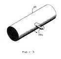
- FIG. 1-3is a perspective view diagram of the rotatable shaft of FIG. 1-1 with a single permanent magnet according to another embodiment of the present invention
- FIG. 2is a perspective view diagram of the rotatable shaft of FIG. 1-1 after forming several magnetic portions in the shaft according to the present invention
- FIG. 3is a perspective view diagram of the axially-directed magnetic polarization induced in the individual magnetic portions according to the present invention
- FIG. 4is a perspective view diagram of the rotatable shaft of FIG. 1-1 after forming several magnetic portions in the shaft according to the present invention
- FIG. 5is a graph showing the output from a magnetic field sensor according to the present invention.
- FIG. 6is a perspective view diagram of the rotatable shaft of FIG. 1-1 showing a placement of magnetic field sensors according to the present invention.
- FIG. 1-1shown therein is a perspective view diagram of a rotatable shaft 105 and a pair of permanent magnets 110a, 110b (collectively 110) being mechanically held such that their end portions are equally in close proximity to the surface of the shaft 105.
- FIG. 1-2is the same perspective view but with the paired magnets 110a, 110b in a different orientation.
- FIG. 1-3is the same perspective view but with a single permanent magnet 110c being used.
- the paired magnets 110a, 110b and single magnet 110cmay be moved toward and away from the shaft 105.
- a first, or initial, positionthe magnets are positioned about 5 inches from the surface of the shaft 105 such that the magnetic fields from the magnets would not reach to the shaft 105.
- the magnets 110a, 110b, 110care shown in a second position. In the second position, the magnets have been advanced toward the surface of the shaft 105 and are held in place there. In that position, the magnets may be as close as 0.5 mm relative to the surface of the shaft 105, or they may actually touch the shaft 105.
- the magnets 110a, 110b, 110cmove at a rate of about 1 to 3 inches per second.
- the magnetsmove at the same or a different rate.
- the magnets 110a, 110b, 110cmay be NdBFe magnets that preferably have a magnetic strength of about 42 MOe or higher.
- the poles of the magnets 110are such that the magnetic flux emanating from the north pole of the magnet 110a closest to the shaft 105 enters the south pole of the magnet 110b closest to the shaft 105. Likewise, to close the magnetic circuit, the flux emanating from the other end of the magnet 110b enters the other end of the magnet 110a. The same thing occurs in the case of a single magnet 110c, but the magnetic flux emanating from the north pole closest to the shaft 105 enters the south pole of the magnet 110c at the other end.
- the shaft 105is locally magnetically polarized due to it being in the path of the magnetic flux from the magnets 110. Any number of these magnetic spots 115 may be generated on and into the shaft 105 by the rotation of the shaft 105 relative to the magnets 110 (in their second position closest to the shaft) or by the repositioning of the magnets 110 relative to the surface of the shaft 105.
- FIG. 2shown therein is a perspective view diagram of the rotatable shaft 105 after forming several magnetic spots 115 in the shaft 105.
- the shaft 105is rotated (or, as noted above, the magnets 110 are rotated relative to the fixed shaft 105), by an angle of, for example, 90 degrees.
- the magnets 110are then advanced from their initial position toward the shaft 105 to form a second magnetic spot 115, and then the magnets 110 are again withdrawn to their initial position. This procedure is repeated until the remaining magnetic spots 115 on the shaft 105 are formed, each using the same procedure described above.
- FIG. 2four magnetic spots 115a, 115b, 115c, and 115d around the shaft 105 have been created.
- the shaft 105/magnets 110are rotated 60 degrees relative to each other after forming the first magnetic spot 115a, then the shaft 105 would be endowed with six magnetic spots 115a, 115b, ..., 115f instead of just four magnetic spots.
- the shaft 105/magnets 110are rotated 30 degree relative to each other after forming the first magnetic spot 115a, then the shaft 105 would be endowed with a total of 12 magnetic spot 115a, 115b, ..., 1151.
- any angular separationcould be used, including, but not limited to, 5, 10, 15, 30, 45, 60, 90 and 120 degrees.
- the aggregate magnetic spots 115begin to approach a continuous band of magnetization.
- the preferred number of magnetic regionsdepends on the accuracy desired and the application in which the shaft 105 will be used. For some applications, 24 magnetic spots are necessary. But the maximum number of magnetic spots is dependent on the diameter of the shaft 105. With permanent magnets 110 having a square cross-section with 2 mm sides, and 1 mm separating the pair of magnets, about 5 mm of space is required for one magnetic spot. Therefore, a shaft 105 having a diameter of about 40 mm would be required to place 24 spots on the shaft.
- the shaft 105is initially prepared by remanently magnetizing it in a circumferential direction, as taught in, for example, U.S. 5,351,555 and U.S. 5,520,059 .
- the material that is not circumferentially magnetizedmay become reactively magnetized from other magnetic sources, including the magnetic portions 115, and thus become a source of parasitic fields.
- the entire cross-section of the shaft 105does not need to be circumferentially magnetized. This is because the torsional shear stress applied at the outer surface of the shaft 105 is reduced as the distance from the surface to the axis of the shaft 105 increases, and thus the relative potential contribution to the magnetic flux signal from the more central regions of the shaft 105 are minimal.
- the axially-directed magnetic polarization 120 induced in the individual magnetic portions 115 by the method described aboveis directed substantially in the axial direction (i.e., longitudinally or x-direction).
- This polarization 120produces an axially-directed "leaking" magnetic field 125 above the surface 135 of the magnetic portion 115, which is also directed substantially in the axial direction of the shaft 105.
- Magnetization in this waycan place more localized magnetic spots 115 on the shaft 105 than using the single magnet 110c as shown in FIG. 1-3 .
- the magnetic fields from the north pole of the magnet 110agoes into the south pole of the magnet 110b, which is attached to the magnet 110a.
- a single magnet like the magnet 110ccan also create magnetic spots, but magnetic spot size becomes larger as magnetic flux lines diverge.
- FIG. 1-2Another method of magnetization is placing the paired magnets as shown in FIG. 1-2 . Magnetic flux lines created from this arrangement are circumferentially directed while the magnetic flux lines created from the arrangement in FIG. 1-1 are directed in an axial direction. The magnetic flux "leakage" appears because the magnetic spots do not form a closed magnetic loop. These leakage fields can be detectable using a fluxgate sensor 130.
- the axial direction of the fluxgate sensor coilsare differently placed above the shaft 105. For example, if the paired magnets 110a, 110b are arranged as shown in FIG.
- the axial direction of the fluxgate sensor coilsshould be parallel to the axis of the shaft 105, since the magnetic flux leakage fields are along the axial direction.
- the paired magnets 110a, 110bare arranged as shown in FIG. 1-2 , then the axial direction of the fluxgate sensors are along the circumferential direction, since the magnetic flux leakage fields are along the circumferential direction.
- the shaftis also circumferentially magnetized for use as, for example, a torque sensor, it is preferred to magnetize the magnetic spots using the arrangement in FIG. 102 as the fluxgate sensor placed parallel to the axial direction of shaft for speed sensor could also detect a torque-induced magnetic flux signal from the shaft 105.
- This external fluxmay be detectable using, as noted above, a fluxgate sensor 130.
- the amount of the external field produced by each of the individual magnetic spots 115should be approximately equal, but this is not required.
- the actual field strengthis less important, because it is the time between peak signals that is important in terms of monitoring the speed of the shaft 105.
- the dimensions of the magnetic spots 115are defined first in the radial direction z, from the outer surface 135 of the shaft 105 to an annular depth d1, which depth is dependant on the strength of the magnets 110, as noted above.
- the magnetic spot 115is defined by the approximate width d2, which may be approximately the width of the permanent magnet pair 110, but could be wider or narrower. As noted above, this dimension could be about 5 mm, if two 2-mm wide magnets are used and spaced about 1 mm apart.
- the physical dimensions of the magnetic spot 115could vary from one magnetic spot 115 to another on the same shaft 105, and they do not have to have the same curved polyhedron shape as depicted in the figure (which is for illustration purposes only). Indeed, the solid lines depicting the extent of the magnetic spots 115 in the shaft 105 in FIG. 2 do not represent a distinct wall separating locally magnetized spots from the rest of the shaft 105. The magnetic spots 115 could have any shape. Precisely forming the magnetic spots 115 to exact dimensions is not important. What is important is that the magnetic spots form an external magnetic field that is detectable as the shaft 105 is rotated by the action of a torque or constant force being applied to the shaft 105.
- the shaft 105does not have to have a uniform diameter along its axial direction, but could have a varying diameter along the length of the shaft 105.
- the magnetized spots 115could taper to a diameter that is less than the diameter of the rest of the shaft 105.
- the shaft 105could also have a step increase or decrease in its diameter at an axially-extending portion relative to the rest of the shaft 105.
- the shaft 105may also be thin-walled (hollow).
- the magnetized spots 115must possess some source of anisotropy to return the magnetization to the established (during the polarization process) direction when the torque is reduced to zero, otherwise, the polarization may be degraded over time after repeated applications of torque. The degradation may be measured by the degree of the external magnetic field sensed by the field sensor 130.
- the anisotropymay be inherent in the nature of the crystalline material making up the shaft 105 (i.e., crystalline anisotropy), or may be imparted in the shaft 105 by any one of several physical treatment processes known in the art.
- the distribution of the local magnetizationsshould predominantly lie in the desired direction, though not all of the local magnetizations must be flipped in that direction during the aforementioned magnetization process. All that is required is that a sufficient number of the local magnetizations be in the desired direction in order for the leaking flux from those portions to sufficiently exceed (1) any parasitic fields arising from portions of the shaft 105 that are not magnetized in the manner described above, (2) any external fields from nearby field-generating sources (near sources); and (3) any background fields from distant sources.
- an oppositely oriented fluxgate sensor coil S2is placed just close ( ⁇ 5 mm) to the fluxgate sensor coil S1 which measures speed signal as shown in FIG. 6 .
- S2is positioned so that it is away from the magnetic spots 115, while S 1 is positioned so that it is near the magnetic spots 115. Therefore, S2 is just used for cancel out near field, compassing, and any other external noise signal.
- FIG. 4shown therein is a perspective view diagram of the rotatable shaft 105 after forming several magnetic portions in the shaft 105 in different axial locations.
- the magnetic spotsare shown in two sets of magnetic spots designated 140a, 140b, ..., 140 n in the first set, and 145a, 145b, ..., 145n in the second set, respectively.
- Each set of magnetic spots 140, 145are separately monitored with a field sensor 150, 155, respectively.
- the number of sets of magnetic spotsis determined by the application of the speed sensor.
- One setmay be used as a backup set of magnetic spots to generate a backup or comparative signal.
- the two sets of magnetic spotsmay be located on different members of a two-member shaft that are interconnected to each other using gears (i.e., a gear box), where the speed of the two member is separately monitored.
- the two sets of magnetic spotscould be on opposite ends of a very long shaft where, when one end may slightly move in advance of the other end, it is important to know the relative speeds of the ends of the shaft. Multiple sets of magnetic spots are necessary for a shaft with smaller diameter, since higher speed sensor resolution is required.
- FIG. 5shown therein is a graph showing the output from a magnetic field sensor (i.e., S1, 130, 150, 155) according to the present invention as the shaft 105 is being rotated at a nearly constant angular speed relative to magnetic field sensor.
- the shaft used in this experimentincluded multiple magnetic spots formed using the method thus described.
- the shaft 105was formed with six magnetic spots 115a, 115b, ..., 115f, each spaced apart from the other along a line oriented substantially circumferentially about the shaft 105, and positioned about 60 degree apart measured in the cross-sectional plane.
- the shaft 105was rotated by the application of a constant force or torque applied to a known position on the shaft 105.
- a magnetic field sensorpositioned near the magnetic spots 115 and oriented to detect the external magnetic field, the output from the field sensor was observed, which had the shape as shown in the graph.
- six peakswere detected during each rotation of the shaft 105 (i.e., six peaks were observed between 0 and 4020 units, six more peaks were observed between 4020 and 8040 units, six more peaks were observed in the next time period, etc.).
- a computational subsystemwhich includes a printed circuit board having at least specific logic circuits, software, a memory device, and a power source.
- the calculated angular speed valuesmay be stored in memory for later downloading to another device.
- the specific calculations performed by the subsystemare described generally above. Expressed as an algorithm, they would include the steps of receiving from a user or embedded in a memory a value representing the circumference of the shaft and/or the angle between the magnetic spots; receiving the signal from the magnetic field sensor in the form of, for example, a voltage; processing the signal using conditioning circuits as needed; determining the time at which a peak signal was detected at the magnetic field sensor; determining the time at which a second peak signal was detected at the magnetic field sensor; adjusting the time values to account for environmental conditions, device-specific factors, lag time, or any other factor that would affect the calculations; calculating the interval of time between the peaks; retrieving the circumference and/or angle value between the plurality of magnetic spots for the shaft; calculating the angular speed; storing and/or outputting the calculated value; and repeating all or some of the above steps.
- the stored valuesmay be overwritten by more recent calculated values such that only the most recent value is stored in the memory.
- the graph in FIG. 5shows distinct and finely resolved peaks, suggesting that many more magnetic spots 115 could be used on the shaft 105 with small separation angles to increase the accuracy and resolution of the measured angular speed of the shaft 105.
- the output signal from the magnetic field sensors S1, S2, 130, 150, and 155could be in the form of an amount of voltage relative to ground.
- the signalmay be processed using known signal conditioning circuits (not shown) to produce a signal useful, for example, displaying a real-time speed value on a display device indicating the actual or average angular speed of the shaft 105, or the speed of another object attached to the shaft 105 (e.g., a vehicle wheel, gear, steering column, drive shaft, auger shaft, propeller, etc.).
- the signalmay also be used as an input to a speed regulating device (e.g., a braking system), or as input to a system monitoring device (e.g., as part of a computerized system for determining a maintenance schedule).
Landscapes
- Physics & Mathematics (AREA)
- General Physics & Mathematics (AREA)
- Transmission And Conversion Of Sensor Element Output (AREA)
- Measurement Of Length, Angles, Or The Like Using Electric Or Magnetic Means (AREA)
- Condensed Matter Physics & Semiconductors (AREA)
Abstract
Description
- This application is related to and claims priority to
U.S. Provisional Appl. 61/182,783, filed June 1, 2009 - This invention is directed to devices for measuring the speed of a rotating shaft using a magnetic speed sensor.
- Speed sensors for rotating shafts are well known in the art. Historically, such devices required some sort of well-defined geometrical structure around a portion of the shaft, such as teeth or grooves, to produce detectable signals representing a change in a magnetic flux. For example, in
U.S. 3,769,533 , which discloses an adaptive braking wheel speed sensor mounted near a vehicle differential, the disclosed device uses a toothed ring attached to the rear wheel axle. The teeth are circumferentially spaced on the outside of the ring. An electro-magnetic pick-up device having a U-shaped core member made of magnetic iron extends close to the teeth so the ends of the core member sense when one of the teeth is near the ends (or when one of the intermediate spaces between the teeth is near). As the rear wheel axle turns, so does the ring and its teeth, which generates a pulsed electrical output in the core member, the frequency of which is proportional to the speed of the rotation of the axle. - In
U.S. 5,223,760 , which also discloses a wheel speed sensor for a drive axle, the disclosed device involves a rotor and circular stator element, each having teeth defining slots formed on the inner face of a the stator element. An axially-poled annular magnet provides a magnetic flux that is sensed with a magnetic flux sensor. The magnetic flux sensor may be a simple multi-turn winding having an axis coincident with the axis of the sensor. The rotor is driven by a shaft and positioned co-axially and nested with the stator elements. The teeth and slots of the elements cooperatively create a time- and position-varying magnetic flux that increases and decreases in the magnetic circuit, indicating the angular velocity of the axle. - These spaced gear teeth in the above patents are magnetized from an external magnetic field source such as those provided by permanent magnets or electromagnets. When magnetized, the gear teeth rotate with the shaft to which they are attached, and produce a sinusoidal-shaped electrical output (voltage) signal which can be processed. A Hall sensor, fluxgate sensor, or the like, is mounted proximate to the gear teeth to receive the fluctuating magnetic field. Though useful, such devices are known to be difficult and expensive to manufacture, as discussed in, for example
U.S. 6,203,464 . - It is therefore desirable to have a speed sensor for a rotating shaft that does not require any projections, indentations, teeth, grooves or other physical manifestations or alterations and thus can be fabricated relatively fast and in a cost-effective manner.
- It is a principle object of the present invention to provide a speed sensing devices for measuring the speed of a rotating shaft using a high resolution, cost effective and fast fabrication magnetic speed sensor.
- It is another object of the present invention to provide a shaft that does not require a separate element which is affixed to the shaft, projects away from the surface of the shaft, or is in relief or sunken-relief relative to the surface of the shaft, for generating a dynamic magnetic flux.
- It is still another object of the present invention to provide a fabrication method for a rotating shaft speed sensor by simply rotating a shaft and using strong magnetic signals from paired magnets which inject strong, local, gradient magnetic fields onto the shaft.
- It is yet another object of the present invention to provide a fabrication method that is less expensive and requires less time to manufacture compared to prior art geared or teeth devices.
- Still another object of the invention is to provide a method for making a speed sensor made from a shaft of generally homogeneous chemical composition throughout, having separate active and passive regions having magnetic properties appropriate for its respective function by endowing each such region with magnetic properties appropriate for its respective function.
- Briefly described, the above and other objects and advantages of the present invention are accomplished, as embodied and fully described herein, by a method for forming a magnetic speed sensor for a rotatable shaft including the steps of forming a plurality of magnetic portions on the shaft, the magnetic portions capable of outputting a magnetic field detectable by at least one magnetic field sensor as the shaft rotates; and positioning the at least one magnetic field sensor near the shaft for outputting a signal corresponding to the angular speed of the shaft as the shaft rotates, wherein the magnetic portions are integrally formed in the shaft by magnetically polarizing the shaft material itself.
- The method includes the step of providing the shaft, a portion of which is first endowed with a magnetic polarization directed substantially in a circumferential direction. The plurality of magnetic portions are approximately equally spaced apart magnetic portions that produce substantially the same or different external magnetic fields. The spaced apart magnetic portions are approximately equally spaced apart at pre-determined angles around the shaft, which may be 5, 10, 15, 30, 45, 60, 90 and 120 degrees apart. Each of the plurality of magnetic portions are formed using a magnetic pair that is positioned close to the shaft at each of the locations of the magnetic portions for a pre-determined time period.
- The above and other objects and advantages of the present invention are also accomplished, as embodied and fully described herein, by a method for operating an angular speed sensor.
- The objects and advantages of the present invention are further accomplished, as embodied and fully described herein, by an apparatus for determining the speed of a rotating shaft, the apparatus including plurality of magnetic portions on a shaft that output a magnetic field from each of the plurality of magnetic portions, wherein the plurality of magnetic portions are integrally formed in the shaft by magnetically polarizing the shaft material itself. The apparatus also includes at least one magnetic field sensor positioned proximate to the shaft for detecting the magnetic field from each of the plurality of magnetic portions and for outputting a signal corresponding to the angular speed of the shaft as the shaft rotates. The apparatus further includes a computation means for calculating the angular speed value of the shaft, and a display device for displaying the calculated speed value. The shaft may be part of a vehicle or other useful device.
FIG. 1-1 is a perspective view diagram of a rotatable shaft and a pair of permanent magnets according to one embodiment of the present invention;FIG.1-2 is a perspective view diagram of the rotatable shaft ofFIG. 1-1 with the pair of permanent magnets in a different orientation according to another embodiment of the present invention;FIG. 1-3 is a perspective view diagram of the rotatable shaft ofFIG. 1-1 with a single permanent magnet according to another embodiment of the present invention;FIG. 2 is a perspective view diagram of the rotatable shaft ofFIG. 1-1 after forming several magnetic portions in the shaft according to the present invention;FIG. 3 is a perspective view diagram of the axially-directed magnetic polarization induced in the individual magnetic portions according to the present invention;FIG. 4 is a perspective view diagram of the rotatable shaft ofFIG. 1-1 after forming several magnetic portions in the shaft according to the present invention;FIG. 5 is a graph showing the output from a magnetic field sensor according to the present invention; andFIG. 6 is a perspective view diagram of the rotatable shaft ofFIG. 1-1 showing a placement of magnetic field sensors according to the present invention.- Several preferred embodiments of the present invention are described for illustrative purposes, it being understood that the invention may be embodied in other forms not specifically shown in the drawings. The figures will be described with respect to the structure and functions that achieve one or more of the objects of the invention and/or receive the benefits derived from the advantages of the invention as understood by persons skilled in the art or explicitly set forth herein.
- Turning first to
FIG. 1-1 , shown therein is a perspective view diagram of arotatable shaft 105 and a pair ofpermanent magnets shaft 105.FIG. 1-2 is the same perspective view but with the pairedmagnets FIG. 1-3 is the same perspective view but with a single permanent magnet 110c being used. - As indicated by the double arrow, the paired
magnets shaft 105. In a first, or initial, position, the magnets are positioned about 5 inches from the surface of theshaft 105 such that the magnetic fields from the magnets would not reach to theshaft 105. In the figures, themagnets shaft 105 and are held in place there. In that position, the magnets may be as close as 0.5 mm relative to the surface of theshaft 105, or they may actually touch theshaft 105. When moved toward the surface of theshaft 105, themagnets shaft 105, the magnets move at the same or a different rate. - The
magnets - The poles of the
magnets 110 are such that the magnetic flux emanating from the north pole of themagnet 110a closest to theshaft 105 enters the south pole of themagnet 110b closest to theshaft 105. Likewise, to close the magnetic circuit, the flux emanating from the other end of themagnet 110b enters the other end of themagnet 110a. The same thing occurs in the case of a single magnet 110c, but the magnetic flux emanating from the north pole closest to theshaft 105 enters the south pole of the magnet 110c at the other end. - In this way, at least a portion of the
shaft 105 is locally magnetically polarized due to it being in the path of the magnetic flux from themagnets 110. Any number of thesemagnetic spots 115 may be generated on and into theshaft 105 by the rotation of theshaft 105 relative to the magnets 110 (in their second position closest to the shaft) or by the repositioning of themagnets 110 relative to the surface of theshaft 105. - The general approach to magnetizing a shaft is taught in, for example,
U.S. 5,351,555 andU.S. 5,520,059 , which describe how the crystalline and magnetic nature of ferromagnetic materials are susceptible to being magnetized by a permanent magnet or an electro-magnet, thereby endowing the ferromagnetic material with a remanent magnetization. As noted in those disclosures, theshaft 105 does not have to be purely iron, as other materials may be included in theshaft 105, including alloy substances and substances that increase or decrease the ability of the material to hold a remanent magnetization. - Turning to
FIG. 2 , shown therein is a perspective view diagram of therotatable shaft 105 after forming severalmagnetic spots 115 in theshaft 105. To form evenly spaced apartmagnetic spots 115, theshaft 105 is rotated (or, as noted above, themagnets 110 are rotated relative to the fixed shaft 105), by an angle of, for example, 90 degrees. Themagnets 110 are then advanced from their initial position toward theshaft 105 to form a secondmagnetic spot 115, and then themagnets 110 are again withdrawn to their initial position. This procedure is repeated until the remainingmagnetic spots 115 on theshaft 105 are formed, each using the same procedure described above. There is no wait time for the second magnetic spot to be created after themagnets 110 are withdrawn from theshaft 105. That is, the nextmagnetic spot 115 may be created right after the preceding spot has been created. In this way, about 1 or 2 minutes are all that are needed to create about sixmagnetic spots 115 on theshaft 105. - To further illustrate, in
FIG. 2 fourmagnetic spots shaft 105 have been created. Of course, instead of 90-degrees, if theshaft 105/magnets 110 are rotated 60 degrees relative to each other after forming the firstmagnetic spot 115a, then theshaft 105 would be endowed with sixmagnetic spots 115a, 115b, ..., 115f instead of just four magnetic spots. Likewise, if theshaft 105/magnets 110 are rotated 30 degree relative to each other after forming the firstmagnetic spot 115a, then theshaft 105 would be endowed with a total of 12magnetic spot 115a, 115b, ..., 1151. Any angular separation could be used, including, but not limited to, 5, 10, 15, 30, 45, 60, 90 and 120 degrees. As moremagnetic spots 115 are added and arranged circumferentially about the axis of theshaft 105, the aggregatemagnetic spots 115 begin to approach a continuous band of magnetization. The preferred number of magnetic regions depends on the accuracy desired and the application in which theshaft 105 will be used. For some applications, 24 magnetic spots are necessary. But the maximum number of magnetic spots is dependent on the diameter of theshaft 105. Withpermanent magnets 110 having a square cross-section with 2 mm sides, and 1 mm separating the pair of magnets, about 5 mm of space is required for one magnetic spot. Therefore, ashaft 105 having a diameter of about 40 mm would be required to place 24 spots on the shaft. - The
shaft 105 is initially prepared by remanently magnetizing it in a circumferential direction, as taught in, for example,U.S. 5,351,555 andU.S. 5,520,059 . The material that is not circumferentially magnetized may become reactively magnetized from other magnetic sources, including themagnetic portions 115, and thus become a source of parasitic fields. The entire cross-section of theshaft 105 does not need to be circumferentially magnetized. This is because the torsional shear stress applied at the outer surface of theshaft 105 is reduced as the distance from the surface to the axis of theshaft 105 increases, and thus the relative potential contribution to the magnetic flux signal from the more central regions of theshaft 105 are minimal. Thus, it is only necessary to circumferentially magnetize theshaft 105 to a depth, in a small diameter shaft, of about 50-percent of the radius of theshaft 105. - Even if deeper regions of the
shaft 105 were to develop field intensities at their location, the contribution from those deep location fields to the field intensity observed at the location where theexternal field sensor 130 is positioned, which is some distance radially outward from the surface of theshaft 105, would be substantially reduced and minimal. Thus, even in very large shafts, the circumferential magnetization deeper than 10-20 mm would provide little benefit. In many hollow shafts, penetrations to such depths would reach to the inside surface. This would be a desirable condition for hollow shafts, especially for thin wall hollow shafts, since they are made hollow in order to more efficiently use the available material strength and to reduce weight. If all of the shaft cross section is transmitting useful torque, it would make sense to have all of the cross section contribute to generating a detectable signal field rather than have some of it detract from the signal field and then contribute to the parasitic fields. As a practical matter, however, it is extremely difficult to magnetize to a depth greater than about 1-2 mm, even on large diameter shafts, because it is difficult to generate a strong enough magnetic field so far from the magnetic field source. - The same factors discussed above also reduce the capability of deeply interior, non-circumferentially magnetized regions to produce significantly troublesome parasitic fields at "distant" field sensors. Thus, while it is desirable to circumferentially magnetize the
shaft 105 to a desirable depth, the fact that the rest of the shaft contains random local magnetizations, some of which may not be oriented circumferentially, is of no importance to the operation of the present invention for speed sensing purposes. - As shown in
FIG. 3 , the axially-directedmagnetic polarization 120 induced in the individualmagnetic portions 115 by the method described above is directed substantially in the axial direction (i.e., longitudinally or x-direction). Thispolarization 120 produces an axially-directed "leaking"magnetic field 125 above thesurface 135 of themagnetic portion 115, which is also directed substantially in the axial direction of theshaft 105. - Magnetization in this way can place more localized
magnetic spots 115 on theshaft 105 than using the single magnet 110c as shown inFIG. 1-3 . InFIG. 1-1 , the magnetic fields from the north pole of themagnet 110a goes into the south pole of themagnet 110b, which is attached to themagnet 110a. A single magnet like the magnet 110c can also create magnetic spots, but magnetic spot size becomes larger as magnetic flux lines diverge. - Another method of magnetization is placing the paired magnets as shown in
FIG. 1-2 . Magnetic flux lines created from this arrangement are circumferentially directed while the magnetic flux lines created from the arrangement inFIG. 1-1 are directed in an axial direction. The magnetic flux "leakage" appears because the magnetic spots do not form a closed magnetic loop. These leakage fields can be detectable using afluxgate sensor 130. Depending upon the arrangement of the paired magnets, the axial direction of the fluxgate sensor coils are differently placed above theshaft 105. For example, if the pairedmagnets FIG. 1-1 , then the axial direction of the fluxgate sensor coils should be parallel to the axis of theshaft 105, since the magnetic flux leakage fields are along the axial direction. If the pairedmagnets FIG. 1-2 , then the axial direction of the fluxgate sensors are along the circumferential direction, since the magnetic flux leakage fields are along the circumferential direction. If the shaft is also circumferentially magnetized for use as, for example, a torque sensor, it is preferred to magnetize the magnetic spots using the arrangement inFIG. 102 as the fluxgate sensor placed parallel to the axial direction of shaft for speed sensor could also detect a torque-induced magnetic flux signal from theshaft 105. - This external flux may be detectable using, as noted above, a
fluxgate sensor 130. The amount of the external field produced by each of the individualmagnetic spots 115 should be approximately equal, but this is not required. The actual field strength is less important, because it is the time between peak signals that is important in terms of monitoring the speed of theshaft 105. - The dimensions of the
magnetic spots 115 are defined first in the radial direction z, from theouter surface 135 of theshaft 105 to an annular depthd1, which depth is dependant on the strength of themagnets 110, as noted above. In the axial direction, themagnetic spot 115 is defined by the approximate widthd2, which may be approximately the width of thepermanent magnet pair 110, but could be wider or narrower. As noted above, this dimension could be about 5 mm, if two 2-mm wide magnets are used and spaced about 1 mm apart. Those of ordinary skill in the art will appreciate that the physical dimensions of themagnetic spot 115 could vary from onemagnetic spot 115 to another on thesame shaft 105, and they do not have to have the same curved polyhedron shape as depicted in the figure (which is for illustration purposes only). Indeed, the solid lines depicting the extent of themagnetic spots 115 in theshaft 105 inFIG. 2 do not represent a distinct wall separating locally magnetized spots from the rest of theshaft 105. Themagnetic spots 115 could have any shape. Precisely forming themagnetic spots 115 to exact dimensions is not important. What is important is that the magnetic spots form an external magnetic field that is detectable as theshaft 105 is rotated by the action of a torque or constant force being applied to theshaft 105. - Also, the
shaft 105 does not have to have a uniform diameter along its axial direction, but could have a varying diameter along the length of theshaft 105. For example, themagnetized spots 115 could taper to a diameter that is less than the diameter of the rest of theshaft 105. Theshaft 105 could also have a step increase or decrease in its diameter at an axially-extending portion relative to the rest of theshaft 105. As noted above, theshaft 105 may also be thin-walled (hollow). - Because the
shaft 105 may undergo an applied torque in its rotating state (i.e., the drive axle of a vehicle during operation), themagnetized spots 115 must possess some source of anisotropy to return the magnetization to the established (during the polarization process) direction when the torque is reduced to zero, otherwise, the polarization may be degraded over time after repeated applications of torque. The degradation may be measured by the degree of the external magnetic field sensed by thefield sensor 130. The anisotropy may be inherent in the nature of the crystalline material making up the shaft 105 (i.e., crystalline anisotropy), or may be imparted in theshaft 105 by any one of several physical treatment processes known in the art. - To ensure a symmetrical "spring back" response to both clockwise and counter-clockwise torques, or from other forces applied to an end of the
shaft 105, the distribution of the local magnetizations should predominantly lie in the desired direction, though not all of the local magnetizations must be flipped in that direction during the aforementioned magnetization process. All that is required is that a sufficient number of the local magnetizations be in the desired direction in order for the leaking flux from those portions to sufficiently exceed (1) any parasitic fields arising from portions of theshaft 105 that are not magnetized in the manner described above, (2) any external fields from nearby field-generating sources (near sources); and (3) any background fields from distant sources. In order to cancel out such noise effects in (1), (2), and (3) above, an oppositely oriented fluxgate sensor coil S2 is placed just close (∼5 mm) to the fluxgate sensor coil S1 which measures speed signal as shown inFIG. 6 . S2 is positioned so that it is away from themagnetic spots 115, whileS 1 is positioned so that it is near themagnetic spots 115. Therefore, S2 is just used for cancel out near field, compassing, and any other external noise signal. - Turning now to
FIG. 4 , shown therein is a perspective view diagram of therotatable shaft 105 after forming several magnetic portions in theshaft 105 in different axial locations. In this case, the magnetic spots are shown in two sets of magnetic spots designated 140a, 140b, ..., 140n in the first set, and 145a, 145b, ..., 145n in the second set, respectively. Each set of magnetic spots 140, 145 are separately monitored with afield sensor - Turning now to
FIG. 5 , shown therein is a graph showing the output from a magnetic field sensor (i.e., S1, 130, 150, 155) according to the present invention as theshaft 105 is being rotated at a nearly constant angular speed relative to magnetic field sensor. The shaft used in this experiment included multiple magnetic spots formed using the method thus described. In particular, theshaft 105 was formed with sixmagnetic spots 115a, 115b, ..., 115f, each spaced apart from the other along a line oriented substantially circumferentially about theshaft 105, and positioned about 60 degree apart measured in the cross-sectional plane. After themagnetic spots 115 were magnetized in the manner described, theshaft 105 was rotated by the application of a constant force or torque applied to a known position on theshaft 105. Using a magnetic field sensor positioned near themagnetic spots 115 and oriented to detect the external magnetic field, the output from the field sensor was observed, which had the shape as shown in the graph. As shown in the graph, six peaks were detected during each rotation of the shaft 105 (i.e., six peaks were observed between 0 and 4020 units, six more peaks were observed between 4020 and 8040 units, six more peaks were observed in the next time period, etc.). - Thus, if the
shaft 105 in the example above had a circumference,C, of 1 unit and themagnetic field sensor 130 detected six peaks corresponding to the sixmagnetic spots 115 during a time period,T, equal to 1 second, the average angular speed of the shaft at the end of the time periodT would beC/T or 1 unit/sec. If twelve peaks were detected at the end of the second period, 2T, or 1.5 seconds (i.e., 1 second for the first rotation and 0.5 second for the second rotation), the average angular speed of the shaft at the end of the second time period would be calculated from 2C/2T or (2 units)/(1.5 sec) = 1.33 units/sec. Of course, instantaneous or near real-time calculations could be made after each peak is detected (the calculations would not be quasi real-time because of the slight delay in detecting the peak signal and processing the signal in the system control circuit (not shown). The above calculations may be done by a computational subsystem, which includes a printed circuit board having at least specific logic circuits, software, a memory device, and a power source. The calculated angular speed values may be stored in memory for later downloading to another device. - The specific calculations performed by the subsystem are described generally above. Expressed as an algorithm, they would include the steps of receiving from a user or embedded in a memory a value representing the circumference of the shaft and/or the angle between the magnetic spots; receiving the signal from the magnetic field sensor in the form of, for example, a voltage; processing the signal using conditioning circuits as needed; determining the time at which a peak signal was detected at the magnetic field sensor; determining the time at which a second peak signal was detected at the magnetic field sensor; adjusting the time values to account for environmental conditions, device-specific factors, lag time, or any other factor that would affect the calculations; calculating the interval of time between the peaks; retrieving the circumference and/or angle value between the plurality of magnetic spots for the shaft; calculating the angular speed; storing and/or outputting the calculated value; and repeating all or some of the above steps. The stored values may be overwritten by more recent calculated values such that only the most recent value is stored in the memory.
- The graph in
FIG. 5 shows distinct and finely resolved peaks, suggesting that many moremagnetic spots 115 could be used on theshaft 105 with small separation angles to increase the accuracy and resolution of the measured angular speed of theshaft 105. - The output signal from the magnetic field sensors S1, S2, 130, 150, and 155 according to the present invention could be in the form of an amount of voltage relative to ground. The signal may be processed using known signal conditioning circuits (not shown) to produce a signal useful, for example, displaying a real-time speed value on a display device indicating the actual or average angular speed of the
shaft 105, or the speed of another object attached to the shaft 105 (e.g., a vehicle wheel, gear, steering column, drive shaft, auger shaft, propeller, etc.). The signal may also be used as an input to a speed regulating device (e.g., a braking system), or as input to a system monitoring device (e.g., as part of a computerized system for determining a maintenance schedule). - Although certain presently preferred embodiments of the disclosed invention have been specifically described herein, it will be apparent to those skilled in the art to which the invention pertains that variations and modifications of the various embodiments shown and described herein may be made without departing from the spirit and scope of the invention. Accordingly, it is intended that the invention be limited only to the extent required by the appended claims and the applicable rules of law.
Claims (24)
Applications Claiming Priority (1)
| Application Number | Priority Date | Filing Date | Title |
|---|---|---|---|
| US18278309P | 2009-06-01 | 2009-06-01 |
Publications (3)
| Publication Number | Publication Date |
|---|---|
| EP2259074A2true EP2259074A2 (en) | 2010-12-08 |
| EP2259074A3 EP2259074A3 (en) | 2012-04-25 |
| EP2259074B1 EP2259074B1 (en) | 2014-03-05 |
Family
ID=42371930
Family Applications (1)
| Application Number | Title | Priority Date | Filing Date |
|---|---|---|---|
| EP10005667.0AActiveEP2259074B1 (en) | 2009-06-01 | 2010-05-31 | Magnetic speed sensor with cost effective and fast fabrication |
Country Status (4)
| Country | Link |
|---|---|
| US (2) | US20100301846A1 (en) |
| EP (1) | EP2259074B1 (en) |
| JP (2) | JP6032863B2 (en) |
| KR (1) | KR101800258B1 (en) |
Cited By (2)
| Publication number | Priority date | Publication date | Assignee | Title |
|---|---|---|---|---|
| US10359324B2 (en) | 2016-08-18 | 2019-07-23 | General Electric Company | Non-contact magnetostrictive sensors and methods of operation of such sensors |
| EP4216252A1 (en)* | 2022-01-19 | 2023-07-26 | Schneider Electric Industries SAS | Monitored switch gear device |
Families Citing this family (10)
| Publication number | Priority date | Publication date | Assignee | Title |
|---|---|---|---|---|
| US20120131753A1 (en)* | 2010-11-29 | 2012-05-31 | General Electric Company | System and method for detecting imbalance in a washing machine |
| WO2012080810A2 (en)* | 2010-12-13 | 2012-06-21 | Schlumberger Technology B.V. | Measuring speed of rotation of a downhole motor |
| US9448087B2 (en) | 2011-10-10 | 2016-09-20 | Methode Electronics, Inc. | Contactless magnetic linear position sensor |
| US8893562B2 (en)* | 2011-11-21 | 2014-11-25 | Methode Electronics, Inc. | System and method for detecting magnetic noise by applying a switching function to magnetic field sensing coils |
| US20140096642A1 (en)* | 2012-10-05 | 2014-04-10 | Remy Technologies, Llc | Starter motor |
| DE102013221673A1 (en)* | 2013-10-24 | 2015-04-30 | Zf Friedrichshafen Ag | Component, device and method for determining an axial position of the component and for speed determination of the component |
| CA2935373A1 (en) | 2013-12-30 | 2015-07-09 | Methode Electronics, Inc. | Magnetoelastic sensor |
| US10254181B2 (en) | 2014-03-26 | 2019-04-09 | Methode Electronics, Inc. | Systems and methods for reducing rotation noise in a magnetoelastic device and measuring torque, speed, and orientation |
| US11198325B2 (en)* | 2019-01-14 | 2021-12-14 | Dino Paoli S.R.L. | Impact tool |
| CN111044747A (en)* | 2019-12-31 | 2020-04-21 | 嘉兴学院 | Sensor for detecting rotating speed |
Citations (5)
| Publication number | Priority date | Publication date | Assignee | Title |
|---|---|---|---|---|
| US3769533A (en) | 1972-05-22 | 1973-10-30 | Bendix Corp | Adaptive braking wheel speed sensor |
| US5223760A (en) | 1988-08-24 | 1993-06-29 | Rockwell International Corporation | Wheel speed sensor for drive axle |
| US5351555A (en) | 1991-07-29 | 1994-10-04 | Magnetoelastic Devices, Inc. | Circularly magnetized non-contact torque sensor and method for measuring torque using same |
| US5520059A (en) | 1991-07-29 | 1996-05-28 | Magnetoelastic Devices, Inc. | Circularly magnetized non-contact torque sensor and method for measuring torque using same |
| US6203464B1 (en) | 1997-10-14 | 2001-03-20 | Kabushiki Kaisha Toyoda Jidoshokki Seisakusho | Support structure for rotation speed sensors |
Family Cites Families (72)
| Publication number | Priority date | Publication date | Assignee | Title |
|---|---|---|---|---|
| JPS4962156A (en)* | 1972-10-16 | 1974-06-17 | ||
| US3932112A (en)* | 1974-07-12 | 1976-01-13 | Garshelis Ivan J | Magnetoelastic, remanent, hysteretic devices |
| US3961297A (en)* | 1974-07-12 | 1976-06-01 | Garshelis Ivan J | Electromagnetic anisotropic devices |
| US3959751A (en)* | 1974-07-12 | 1976-05-25 | Garshelis Ivan J | Electromechanical transducer having circularly magnetized helically wound magnetostrictive rod |
| US4012959A (en)* | 1974-07-12 | 1977-03-22 | Garshelis Ivan J | Pressure gauge and flow meter |
| US4188572A (en)* | 1974-07-12 | 1980-02-12 | Garshelis Ivan J | Current sensing device |
| US3939448A (en)* | 1974-07-12 | 1976-02-17 | Garshelis Ivan J | Mechanical magnets of magnetostrictive, remanent, circularly magnetized material |
| JPS60250211A (en)* | 1984-05-28 | 1985-12-10 | Inoue Japax Res Inc | Manufacture of magnetic scale |
| US4760745A (en)* | 1986-12-05 | 1988-08-02 | Mag Dev Inc. | Magnetoelastic torque transducer |
| US4896544A (en)* | 1986-12-05 | 1990-01-30 | Mag Dev Inc. | Magnetoelastic torque transducer |
| JPS63238426A (en)* | 1987-03-26 | 1988-10-04 | Yamaha Corp | Manufacture of magnetic encoder |
| JPH067058B2 (en)* | 1987-03-26 | 1994-01-26 | ヤマハ株式会社 | Magnetic encoder |
| JPS63156075U (en)* | 1987-03-31 | 1988-10-13 | ||
| JPS63250519A (en)* | 1987-04-06 | 1988-10-18 | Dai Ichi Seiko Co Ltd | Magnetizing device for magnetic scale |
| JPH01189517A (en)* | 1988-01-26 | 1989-07-28 | Yamaha Corp | Magnetic encoder |
| JPH01189516A (en)* | 1988-01-26 | 1989-07-28 | Yamaha Corp | Magnetic resistance sensor for magnetic encoder |
| JPH02503235A (en)* | 1988-02-11 | 1990-10-04 | ガーシェリス、イヴァン ジェイ | magnetic position detector |
| US5195377A (en)* | 1990-04-17 | 1993-03-23 | Garshelis Ivan J | Magnetoelastic force transducer for sensing force applied to a ferromagnetic member using leakage flux measurement |
| JPH04301517A (en)* | 1991-03-29 | 1992-10-26 | Mazda Motor Corp | Position detector |
| US5591925A (en)* | 1991-07-29 | 1997-01-07 | Garshelis; Ivan J. | Circularly magnetized non-contact power sensor and method for measuring torque and power using same |
| JPH0536001A (en)* | 1991-07-29 | 1993-02-12 | Mazda Motor Corp | Magnetizing method for magnetic recording body and magnetic recording body |
| US5367257A (en)* | 1992-05-14 | 1994-11-22 | Garshelis Ivan J | Non-contact, magnetic sensor for determining direction of motion and velocity of a movable member |
| JPH0634390A (en)* | 1992-07-15 | 1994-02-08 | Hitachi Ltd | Position detector |
| EP0606942A1 (en)* | 1993-01-15 | 1994-07-20 | Magnavox Electronic Systems Company | Angular speed and position measuring device and method |
| JP3388466B2 (en)* | 1993-03-17 | 2003-03-24 | 株式会社共立 | Measuring device |
| JPH1090009A (en)* | 1996-09-17 | 1998-04-10 | Kubota Corp | Work machine display |
| JP3200028B2 (en)* | 1996-09-27 | 2001-08-20 | キヤノン電子株式会社 | Tire magnetization method and tire magnetic field detection method |
| GB9709710D0 (en)* | 1997-05-13 | 1997-07-02 | Fet Electronics Ltd | Conditioner circuit for torque sensor |
| US6047605A (en)* | 1997-10-21 | 2000-04-11 | Magna-Lastic Devices, Inc. | Collarless circularly magnetized torque transducer having two phase shaft and method for measuring torque using same |
| GB9808792D0 (en)* | 1998-04-23 | 1998-06-24 | Effective Torque Technologies | Magnetising arrangements for torque/force sensor |
| GB9906735D0 (en)* | 1999-03-23 | 1999-05-19 | Fet Applic Limited | Magnoelastic transducers |
| GB9919065D0 (en)* | 1999-08-12 | 1999-10-13 | Fast Technology Gmbh | Transducer Element |
| GB9923894D0 (en)* | 1999-10-08 | 1999-12-08 | Fast Technology Gmbh | Accelerometer |
| GB9924046D0 (en)* | 1999-10-11 | 1999-12-15 | Fast Technology Gmbh | Torque measurement apparatus |
| JP2001165946A (en)* | 1999-12-10 | 2001-06-22 | Sumitomo Electric Ind Ltd | Rotation speed detection device and rotation shaft used for it |
| US6360841B1 (en)* | 2000-02-29 | 2002-03-26 | Trw Inc. | Power steering mechanism with magnetoelastic torsion bar |
| GB0007532D0 (en)* | 2000-03-28 | 2000-05-17 | Fast Technology Gmbh | Magnetic-based force/torque sensing |
| GB0009492D0 (en)* | 2000-04-17 | 2000-06-07 | Fast Technology Gmbh | Magnetic transducer element and method of preparation |
| GB0012226D0 (en)* | 2000-05-19 | 2000-07-12 | Fast Technology Gmbh | Magnetic-based torque/speed sensor |
| JP4453058B2 (en)* | 2000-05-23 | 2010-04-21 | 日立金属株式会社 | Magnetic encoder |
| US7124649B2 (en)* | 2000-06-14 | 2006-10-24 | Abas, Inc. | Magnetic transducer torque measurement |
| AU2002213899A1 (en)* | 2000-09-12 | 2002-03-26 | Fast Technology Ag. | Magnetic torque sensor system |
| AT4639U1 (en)* | 2000-10-23 | 2001-09-25 | Austria Mikrosysteme Int | ANGLE MEASURING DEVICE |
| JP2002264785A (en)* | 2001-03-08 | 2002-09-18 | Bridgestone Corp | Abs, vehicle provided with the same, pneumatic tyre, and control method for abs |
| GB0114279D0 (en)* | 2001-06-12 | 2001-08-01 | Fast Technology Ag | Disc magnetic torque sensing |
| CA2450137A1 (en)* | 2001-06-25 | 2003-01-03 | Lutz Axel May | Power torque tool |
| GB0129510D0 (en)* | 2001-12-10 | 2002-01-30 | Fast Technology Ag | Magnetic torque transducer |
| GB0204213D0 (en)* | 2002-02-22 | 2002-04-10 | Fast Technology Ag | Pulsed torque measurement |
| GB2402491B (en)* | 2002-02-22 | 2005-08-24 | Fast Technology Ag | Magnetically neutral displacement (torque) transducer for a ferromagnetic member with coil(s) and magnetic field sensor(s) |
| JP2003254347A (en)* | 2002-03-07 | 2003-09-10 | Koyo Seiko Co Ltd | Bearing unit with sensor |
| US7521923B2 (en)* | 2002-04-23 | 2009-04-21 | Abas, Incorporated | Magnetic displacement transducer |
| GB0219745D0 (en)* | 2002-08-23 | 2002-10-02 | Fast Technology Ag | Torque sensor adaptor |
| EP1439035A1 (en)* | 2002-12-16 | 2004-07-21 | Fast Technology AG | Signal processing and control device for a power torque tool |
| US20080313886A1 (en)* | 2003-12-30 | 2008-12-25 | Lutz May | Methods and Apparatuses for Magnetizing an Object and for Calibrating a Sensor Device |
| WO2006013093A2 (en)* | 2004-08-02 | 2006-02-09 | Nctengineering Gmbh | Sensor electronic |
| US20070247224A1 (en)* | 2004-08-02 | 2007-10-25 | Lutz May | Sensor Electronic |
| BRPI0607124A2 (en)* | 2005-02-01 | 2009-08-04 | Nct Engineering Gmbh | position sensor and washing machine |
| EP1859458B1 (en)* | 2005-03-16 | 2012-02-15 | NCTEngineering GmbH | A method and an array for magnetizing a magnetizable object |
| GB0512045D0 (en)* | 2005-06-14 | 2005-07-20 | Equipmake Ltd | Rotation sensing |
| DE602005014352D1 (en)* | 2005-07-11 | 2009-06-18 | Nct Engineering Gmbh | Rotation angle sensor |
| WO2007017136A1 (en)* | 2005-07-27 | 2007-02-15 | Nctengineering Gmbh | Position sensing |
| US8058865B2 (en)* | 2005-08-30 | 2011-11-15 | Nctengineering Gmbh | Sensor device, sensor arrangement, and method of measuring a property of an object |
| US7437942B2 (en)* | 2005-10-30 | 2008-10-21 | Magcanica, Inc. | Non-destructive evaluation via measurement of magnetic drag force |
| US20090021244A1 (en)* | 2005-12-15 | 2009-01-22 | Lutz May | Sensor |
| EP2027438A2 (en)* | 2006-05-29 | 2009-02-25 | NCTEngineering GmbH | Sensor device and method of measuring a position of an object |
| JP2010515885A (en)* | 2007-01-06 | 2010-05-13 | マグカニカ・インコーポレイテッド | Apparatus and method for detecting rate of change of torque |
| JP2008298729A (en)* | 2007-06-04 | 2008-12-11 | Nikkoshi Co Ltd | Magnetic scale for magnetic type encoder and manufacturing method thereof |
| WO2009000604A1 (en)* | 2007-06-28 | 2008-12-31 | Nctengineering Gmbh | Magnetic sensor arrangement for defined force transmission |
| JP5116576B2 (en)* | 2007-06-29 | 2013-01-09 | メレクシス テッセンデルロ エヌヴィ | Magnetic structure for detecting relative motion between a magnetic structure and a magnetic field sensor |
| US8020455B2 (en)* | 2008-06-06 | 2011-09-20 | General Electric Company | Magnetostrictive sensing systems and methods for encoding |
| FR2951265B1 (en)* | 2009-10-14 | 2013-02-08 | Electricfil Automotive | MAGNETIC SENSOR FOR DETERMINING THE POSITION AND ORIENTATION OF A TARGET |
| US20110213571A1 (en)* | 2010-02-26 | 2011-09-01 | General Electric Company | Sectional magnetic encoding method and system for measuring rotating shaft parameters |
- 2010
- 2010-05-28USUS12/790,350patent/US20100301846A1/ennot_activeAbandoned
- 2010-05-31EPEP10005667.0Apatent/EP2259074B1/enactiveActive
- 2010-06-01KRKR1020100051697Apatent/KR101800258B1/ennot_activeExpired - Fee Related
- 2010-06-01JPJP2010125745Apatent/JP6032863B2/ennot_activeExpired - Fee Related
- 2016
- 2016-01-28JPJP2016014412Apatent/JP2016075711A/enactivePending
- 2019
- 2019-04-16USUS16/385,172patent/US20190242922A1/ennot_activeAbandoned
Patent Citations (5)
| Publication number | Priority date | Publication date | Assignee | Title |
|---|---|---|---|---|
| US3769533A (en) | 1972-05-22 | 1973-10-30 | Bendix Corp | Adaptive braking wheel speed sensor |
| US5223760A (en) | 1988-08-24 | 1993-06-29 | Rockwell International Corporation | Wheel speed sensor for drive axle |
| US5351555A (en) | 1991-07-29 | 1994-10-04 | Magnetoelastic Devices, Inc. | Circularly magnetized non-contact torque sensor and method for measuring torque using same |
| US5520059A (en) | 1991-07-29 | 1996-05-28 | Magnetoelastic Devices, Inc. | Circularly magnetized non-contact torque sensor and method for measuring torque using same |
| US6203464B1 (en) | 1997-10-14 | 2001-03-20 | Kabushiki Kaisha Toyoda Jidoshokki Seisakusho | Support structure for rotation speed sensors |
Cited By (4)
| Publication number | Priority date | Publication date | Assignee | Title |
|---|---|---|---|---|
| US10359324B2 (en) | 2016-08-18 | 2019-07-23 | General Electric Company | Non-contact magnetostrictive sensors and methods of operation of such sensors |
| US11486773B2 (en) | 2016-08-18 | 2022-11-01 | Baker Hughes, A Ge Company, Llc | Non-contact magnetostrictive sensors and methods of operation of such sensors |
| EP4216252A1 (en)* | 2022-01-19 | 2023-07-26 | Schneider Electric Industries SAS | Monitored switch gear device |
| US12210062B2 (en) | 2022-01-19 | 2025-01-28 | Schneider Electric Industries Sas | Monitored switch gear device |
Also Published As
| Publication number | Publication date |
|---|---|
| KR101800258B1 (en) | 2017-12-20 |
| KR20100129708A (en) | 2010-12-09 |
| EP2259074B1 (en) | 2014-03-05 |
| EP2259074A3 (en) | 2012-04-25 |
| JP6032863B2 (en) | 2016-11-30 |
| JP2016075711A (en) | 2016-05-12 |
| US20190242922A1 (en) | 2019-08-08 |
| US20100301846A1 (en) | 2010-12-02 |
| JP2011043492A (en) | 2011-03-03 |
Similar Documents
| Publication | Publication Date | Title |
|---|---|---|
| US20190242922A1 (en) | Magnetic speed sensor and method of making the same | |
| EP1203210B1 (en) | Magnetised transducer element for torque or force sensor | |
| US6581480B1 (en) | Magnetising arrangements for torque/force sensor | |
| EP2972167B1 (en) | System and method for reducing rotation noise in a magnetoelastic torque sensing device | |
| KR102030555B1 (en) | Magnetic torque sensor for transmission converter drive plate | |
| EP0829001B1 (en) | Circularly magnetized non-contact torque and power sensor and method for measuring torque and power using same | |
| EP1826534B1 (en) | Rotation angle detecting device | |
| JP2016004039A5 (en) | ||
| KR102015824B1 (en) | Magnetic torque sensing device | |
| US20110121823A1 (en) | Meshing encoder gear and sensor assembly | |
| US7024946B2 (en) | Assembly for measuring movement of and a torque applied to a shaft | |
| EP3123133B1 (en) | Systems and methods for reducing rotation noise in a magnetoelastic device and measuring torque, speed, and orientation | |
| JPH01276033A (en) | Micro displacement detection device |
Legal Events
| Date | Code | Title | Description |
|---|---|---|---|
| PUAI | Public reference made under article 153(3) epc to a published international application that has entered the european phase | Free format text:ORIGINAL CODE: 0009012 | |
| AK | Designated contracting states | Kind code of ref document:A2 Designated state(s):AL AT BE BG CH CY CZ DE DK EE ES FI FR GB GR HR HU IE IS IT LI LT LU LV MC MK MT NL NO PL PT RO SE SI SK SM TR | |
| AX | Request for extension of the european patent | Extension state:BA ME RS | |
| PUAL | Search report despatched | Free format text:ORIGINAL CODE: 0009013 | |
| AK | Designated contracting states | Kind code of ref document:A3 Designated state(s):AL AT BE BG CH CY CZ DE DK EE ES FI FR GB GR HR HU IE IS IT LI LT LU LV MC MK MT NL NO PL PT RO SE SI SK SM TR | |
| AX | Request for extension of the european patent | Extension state:BA ME RS | |
| RIC1 | Information provided on ipc code assigned before grant | Ipc:G01P 3/487 20060101AFI20120319BHEP | |
| RAP1 | Party data changed (applicant data changed or rights of an application transferred) | Owner name:METHODE ELECTRONICS, INC. | |
| 17P | Request for examination filed | Effective date:20121025 | |
| 17Q | First examination report despatched | Effective date:20130108 | |
| GRAP | Despatch of communication of intention to grant a patent | Free format text:ORIGINAL CODE: EPIDOSNIGR1 | |
| INTG | Intention to grant announced | Effective date:20130927 | |
| GRAS | Grant fee paid | Free format text:ORIGINAL CODE: EPIDOSNIGR3 | |
| GRAA | (expected) grant | Free format text:ORIGINAL CODE: 0009210 | |
| AK | Designated contracting states | Kind code of ref document:B1 Designated state(s):AL AT BE BG CH CY CZ DE DK EE ES FI FR GB GR HR HU IE IS IT LI LT LU LV MC MK MT NL NO PL PT RO SE SI SK SM TR | |
| REG | Reference to a national code | Ref country code:GB Ref legal event code:FG4D | |
| REG | Reference to a national code | Ref country code:CH Ref legal event code:EP | |
| REG | Reference to a national code | Ref country code:AT Ref legal event code:REF Ref document number:655215 Country of ref document:AT Kind code of ref document:T Effective date:20140315 | |
| REG | Reference to a national code | Ref country code:CH Ref legal event code:NV Representative=s name:BUGNION S.A., CH | |
| REG | Reference to a national code | Ref country code:IE Ref legal event code:FG4D | |
| REG | Reference to a national code | Ref country code:DE Ref legal event code:R096 Ref document number:602010013885 Country of ref document:DE Effective date:20140417 | |
| REG | Reference to a national code | Ref country code:SE Ref legal event code:TRGR | |
| REG | Reference to a national code | Ref country code:AT Ref legal event code:MK05 Ref document number:655215 Country of ref document:AT Kind code of ref document:T Effective date:20140305 | |
| REG | Reference to a national code | Ref country code:NL Ref legal event code:VDEP Effective date:20140305 | |
| PG25 | Lapsed in a contracting state [announced via postgrant information from national office to epo] | Ref country code:NO Free format text:LAPSE BECAUSE OF FAILURE TO SUBMIT A TRANSLATION OF THE DESCRIPTION OR TO PAY THE FEE WITHIN THE PRESCRIBED TIME-LIMIT Effective date:20140605 Ref country code:LT Free format text:LAPSE BECAUSE OF FAILURE TO SUBMIT A TRANSLATION OF THE DESCRIPTION OR TO PAY THE FEE WITHIN THE PRESCRIBED TIME-LIMIT Effective date:20140305 | |
| REG | Reference to a national code | Ref country code:LT Ref legal event code:MG4D | |
| PG25 | Lapsed in a contracting state [announced via postgrant information from national office to epo] | Ref country code:AT Free format text:LAPSE BECAUSE OF FAILURE TO SUBMIT A TRANSLATION OF THE DESCRIPTION OR TO PAY THE FEE WITHIN THE PRESCRIBED TIME-LIMIT Effective date:20140305 Ref country code:CY Free format text:LAPSE BECAUSE OF FAILURE TO SUBMIT A TRANSLATION OF THE DESCRIPTION OR TO PAY THE FEE WITHIN THE PRESCRIBED TIME-LIMIT Effective date:20140305 Ref country code:FI Free format text:LAPSE BECAUSE OF FAILURE TO SUBMIT A TRANSLATION OF THE DESCRIPTION OR TO PAY THE FEE WITHIN THE PRESCRIBED TIME-LIMIT Effective date:20140305 | |
| PG25 | Lapsed in a contracting state [announced via postgrant information from national office to epo] | Ref country code:LV Free format text:LAPSE BECAUSE OF FAILURE TO SUBMIT A TRANSLATION OF THE DESCRIPTION OR TO PAY THE FEE WITHIN THE PRESCRIBED TIME-LIMIT Effective date:20140305 Ref country code:HR Free format text:LAPSE BECAUSE OF FAILURE TO SUBMIT A TRANSLATION OF THE DESCRIPTION OR TO PAY THE FEE WITHIN THE PRESCRIBED TIME-LIMIT Effective date:20140305 | |
| PG25 | Lapsed in a contracting state [announced via postgrant information from national office to epo] | Ref country code:BE Free format text:LAPSE BECAUSE OF FAILURE TO SUBMIT A TRANSLATION OF THE DESCRIPTION OR TO PAY THE FEE WITHIN THE PRESCRIBED TIME-LIMIT Effective date:20140305 Ref country code:RO Free format text:LAPSE BECAUSE OF FAILURE TO SUBMIT A TRANSLATION OF THE DESCRIPTION OR TO PAY THE FEE WITHIN THE PRESCRIBED TIME-LIMIT Effective date:20140305 Ref country code:IS Free format text:LAPSE BECAUSE OF FAILURE TO SUBMIT A TRANSLATION OF THE DESCRIPTION OR TO PAY THE FEE WITHIN THE PRESCRIBED TIME-LIMIT Effective date:20140705 Ref country code:CZ Free format text:LAPSE BECAUSE OF FAILURE TO SUBMIT A TRANSLATION OF THE DESCRIPTION OR TO PAY THE FEE WITHIN THE PRESCRIBED TIME-LIMIT Effective date:20140305 Ref country code:EE Free format text:LAPSE BECAUSE OF FAILURE TO SUBMIT A TRANSLATION OF THE DESCRIPTION OR TO PAY THE FEE WITHIN THE PRESCRIBED TIME-LIMIT Effective date:20140305 Ref country code:BG Free format text:LAPSE BECAUSE OF FAILURE TO SUBMIT A TRANSLATION OF THE DESCRIPTION OR TO PAY THE FEE WITHIN THE PRESCRIBED TIME-LIMIT Effective date:20140605 Ref country code:NL Free format text:LAPSE BECAUSE OF FAILURE TO SUBMIT A TRANSLATION OF THE DESCRIPTION OR TO PAY THE FEE WITHIN THE PRESCRIBED TIME-LIMIT Effective date:20140305 | |
| PG25 | Lapsed in a contracting state [announced via postgrant information from national office to epo] | Ref country code:PL Free format text:LAPSE BECAUSE OF FAILURE TO SUBMIT A TRANSLATION OF THE DESCRIPTION OR TO PAY THE FEE WITHIN THE PRESCRIBED TIME-LIMIT Effective date:20140305 Ref country code:ES Free format text:LAPSE BECAUSE OF FAILURE TO SUBMIT A TRANSLATION OF THE DESCRIPTION OR TO PAY THE FEE WITHIN THE PRESCRIBED TIME-LIMIT Effective date:20140305 Ref country code:SK Free format text:LAPSE BECAUSE OF FAILURE TO SUBMIT A TRANSLATION OF THE DESCRIPTION OR TO PAY THE FEE WITHIN THE PRESCRIBED TIME-LIMIT Effective date:20140305 | |
| REG | Reference to a national code | Ref country code:DE Ref legal event code:R097 Ref document number:602010013885 Country of ref document:DE | |
| PG25 | Lapsed in a contracting state [announced via postgrant information from national office to epo] | Ref country code:LU Free format text:LAPSE BECAUSE OF FAILURE TO SUBMIT A TRANSLATION OF THE DESCRIPTION OR TO PAY THE FEE WITHIN THE PRESCRIBED TIME-LIMIT Effective date:20140531 Ref country code:PT Free format text:LAPSE BECAUSE OF FAILURE TO SUBMIT A TRANSLATION OF THE DESCRIPTION OR TO PAY THE FEE WITHIN THE PRESCRIBED TIME-LIMIT Effective date:20140707 | |
| PLBE | No opposition filed within time limit | Free format text:ORIGINAL CODE: 0009261 | |
| STAA | Information on the status of an ep patent application or granted ep patent | Free format text:STATUS: NO OPPOSITION FILED WITHIN TIME LIMIT | |
| PG25 | Lapsed in a contracting state [announced via postgrant information from national office to epo] | Ref country code:DK Free format text:LAPSE BECAUSE OF FAILURE TO SUBMIT A TRANSLATION OF THE DESCRIPTION OR TO PAY THE FEE WITHIN THE PRESCRIBED TIME-LIMIT Effective date:20140305 Ref country code:MC Free format text:LAPSE BECAUSE OF FAILURE TO SUBMIT A TRANSLATION OF THE DESCRIPTION OR TO PAY THE FEE WITHIN THE PRESCRIBED TIME-LIMIT Effective date:20140305 | |
| 26N | No opposition filed | Effective date:20141208 | |
| REG | Reference to a national code | Ref country code:IE Ref legal event code:MM4A | |
| REG | Reference to a national code | Ref country code:DE Ref legal event code:R097 Ref document number:602010013885 Country of ref document:DE Effective date:20141208 | |
| PG25 | Lapsed in a contracting state [announced via postgrant information from national office to epo] | Ref country code:IE Free format text:LAPSE BECAUSE OF NON-PAYMENT OF DUE FEES Effective date:20140531 | |
| REG | Reference to a national code | Ref country code:FR Ref legal event code:PLFP Year of fee payment:6 | |
| PG25 | Lapsed in a contracting state [announced via postgrant information from national office to epo] | Ref country code:SI Free format text:LAPSE BECAUSE OF FAILURE TO SUBMIT A TRANSLATION OF THE DESCRIPTION OR TO PAY THE FEE WITHIN THE PRESCRIBED TIME-LIMIT Effective date:20140305 | |
| PG25 | Lapsed in a contracting state [announced via postgrant information from national office to epo] | Ref country code:MT Free format text:LAPSE BECAUSE OF FAILURE TO SUBMIT A TRANSLATION OF THE DESCRIPTION OR TO PAY THE FEE WITHIN THE PRESCRIBED TIME-LIMIT Effective date:20140305 | |
| REG | Reference to a national code | Ref country code:FR Ref legal event code:PLFP Year of fee payment:7 | |
| PG25 | Lapsed in a contracting state [announced via postgrant information from national office to epo] | Ref country code:SM Free format text:LAPSE BECAUSE OF FAILURE TO SUBMIT A TRANSLATION OF THE DESCRIPTION OR TO PAY THE FEE WITHIN THE PRESCRIBED TIME-LIMIT Effective date:20140305 | |
| PG25 | Lapsed in a contracting state [announced via postgrant information from national office to epo] | Ref country code:GR Free format text:LAPSE BECAUSE OF FAILURE TO SUBMIT A TRANSLATION OF THE DESCRIPTION OR TO PAY THE FEE WITHIN THE PRESCRIBED TIME-LIMIT Effective date:20140606 | |
| PG25 | Lapsed in a contracting state [announced via postgrant information from national office to epo] | Ref country code:HU Free format text:LAPSE BECAUSE OF FAILURE TO SUBMIT A TRANSLATION OF THE DESCRIPTION OR TO PAY THE FEE WITHIN THE PRESCRIBED TIME-LIMIT; INVALID AB INITIO Effective date:20100531 Ref country code:TR Free format text:LAPSE BECAUSE OF FAILURE TO SUBMIT A TRANSLATION OF THE DESCRIPTION OR TO PAY THE FEE WITHIN THE PRESCRIBED TIME-LIMIT Effective date:20140305 | |
| REG | Reference to a national code | Ref country code:FR Ref legal event code:PLFP Year of fee payment:8 | |
| REG | Reference to a national code | Ref country code:FR Ref legal event code:PLFP Year of fee payment:9 | |
| PG25 | Lapsed in a contracting state [announced via postgrant information from national office to epo] | Ref country code:MK Free format text:LAPSE BECAUSE OF FAILURE TO SUBMIT A TRANSLATION OF THE DESCRIPTION OR TO PAY THE FEE WITHIN THE PRESCRIBED TIME-LIMIT Effective date:20140305 | |
| PG25 | Lapsed in a contracting state [announced via postgrant information from national office to epo] | Ref country code:AL Free format text:LAPSE BECAUSE OF FAILURE TO SUBMIT A TRANSLATION OF THE DESCRIPTION OR TO PAY THE FEE WITHIN THE PRESCRIBED TIME-LIMIT Effective date:20140305 | |
| PGFP | Annual fee paid to national office [announced via postgrant information from national office to epo] | Ref country code:IT Payment date:20210412 Year of fee payment:12 Ref country code:FR Payment date:20210412 Year of fee payment:12 | |
| PGFP | Annual fee paid to national office [announced via postgrant information from national office to epo] | Ref country code:SE Payment date:20210511 Year of fee payment:12 Ref country code:CH Payment date:20210519 Year of fee payment:12 Ref country code:GB Payment date:20210505 Year of fee payment:12 | |
| REG | Reference to a national code | Ref country code:CH Ref legal event code:PL | |
| GBPC | Gb: european patent ceased through non-payment of renewal fee | Effective date:20220531 | |
| PG25 | Lapsed in a contracting state [announced via postgrant information from national office to epo] | Ref country code:LI Free format text:LAPSE BECAUSE OF NON-PAYMENT OF DUE FEES Effective date:20220531 Ref country code:CH Free format text:LAPSE BECAUSE OF NON-PAYMENT OF DUE FEES Effective date:20220531 | |
| REG | Reference to a national code | Ref country code:SE Ref legal event code:EUG | |
| PG25 | Lapsed in a contracting state [announced via postgrant information from national office to epo] | Ref country code:SE Free format text:LAPSE BECAUSE OF NON-PAYMENT OF DUE FEES Effective date:20220601 Ref country code:FR Free format text:LAPSE BECAUSE OF NON-PAYMENT OF DUE FEES Effective date:20220531 | |
| PG25 | Lapsed in a contracting state [announced via postgrant information from national office to epo] | Ref country code:GB Free format text:LAPSE BECAUSE OF NON-PAYMENT OF DUE FEES Effective date:20220531 | |
| REG | Reference to a national code | Ref country code:DE Ref legal event code:R082 Ref document number:602010013885 Country of ref document:DE Representative=s name:LS-MP VON PUTTKAMER BERNGRUBER LOTH SPUHLER MU, DE | |
| PG25 | Lapsed in a contracting state [announced via postgrant information from national office to epo] | Ref country code:IT Free format text:LAPSE BECAUSE OF NON-PAYMENT OF DUE FEES Effective date:20220531 | |
| P01 | Opt-out of the competence of the unified patent court (upc) registered | Effective date:20230629 | |
| PGFP | Annual fee paid to national office [announced via postgrant information from national office to epo] | Ref country code:DE Payment date:20250528 Year of fee payment:16 |