EP2258290B1 - Humeral nail for humerus fractures - Google Patents
Humeral nail for humerus fracturesDownload PDFInfo
- Publication number
- EP2258290B1 EP2258290B1EP10001409.1AEP10001409AEP2258290B1EP 2258290 B1EP2258290 B1EP 2258290B1EP 10001409 AEP10001409 AEP 10001409AEP 2258290 B1EP2258290 B1EP 2258290B1
- Authority
- EP
- European Patent Office
- Prior art keywords
- nail
- humeral
- stabilizing element
- humeral nail
- opening
- Prior art date
- Legal status (The legal status is an assumption and is not a legal conclusion. Google has not performed a legal analysis and makes no representation as to the accuracy of the status listed.)
- Active
Links
- 206010020462Humerus fractureDiseases0.000titledescription2
- 210000002758humerusAnatomy0.000claimsdescription19
- 230000037431insertionEffects0.000claimsdescription5
- 238000003780insertionMethods0.000claimsdescription5
- 230000003019stabilising effectEffects0.000claims12
- 230000000087stabilizing effectEffects0.000description69
- 230000006641stabilisationEffects0.000description13
- 238000011105stabilizationMethods0.000description13
- 210000000988bone and boneAnatomy0.000description12
- 210000004095humeral headAnatomy0.000description5
- 230000008685targetingEffects0.000description4
- 206010017076FractureDiseases0.000description3
- 238000006073displacement reactionMethods0.000description2
- 238000005553drillingMethods0.000description2
- 210000000513rotator cuffAnatomy0.000description2
- 208000007981Humeral FracturesDiseases0.000description1
- 239000004570mortar (masonry)Substances0.000description1
- 230000001681protective effectEffects0.000description1
- 210000000689upper legAnatomy0.000description1
Images


Classifications
- A—HUMAN NECESSITIES
- A61—MEDICAL OR VETERINARY SCIENCE; HYGIENE
- A61B—DIAGNOSIS; SURGERY; IDENTIFICATION
- A61B17/00—Surgical instruments, devices or methods
- A61B17/56—Surgical instruments or methods for treatment of bones or joints; Devices specially adapted therefor
- A61B17/58—Surgical instruments or methods for treatment of bones or joints; Devices specially adapted therefor for osteosynthesis, e.g. bone plates, screws or setting implements
- A61B17/68—Internal fixation devices, including fasteners and spinal fixators, even if a part thereof projects from the skin
- A61B17/72—Intramedullary devices, e.g. pins or nails
- A61B17/7233—Intramedullary devices, e.g. pins or nails with special means of locking the nail to the bone
- A61B17/725—Intramedullary devices, e.g. pins or nails with special means of locking the nail to the bone with locking pins or screws of special form
- A—HUMAN NECESSITIES
- A61—MEDICAL OR VETERINARY SCIENCE; HYGIENE
- A61B—DIAGNOSIS; SURGERY; IDENTIFICATION
- A61B17/00—Surgical instruments, devices or methods
- A61B17/16—Instruments for performing osteoclasis; Drills or chisels for bones; Trepans
- A61B17/17—Guides or aligning means for drills, mills, pins or wires
- A61B17/1739—Guides or aligning means for drills, mills, pins or wires specially adapted for particular parts of the body
- A61B17/1778—Guides or aligning means for drills, mills, pins or wires specially adapted for particular parts of the body for the shoulder
- A—HUMAN NECESSITIES
- A61—MEDICAL OR VETERINARY SCIENCE; HYGIENE
- A61B—DIAGNOSIS; SURGERY; IDENTIFICATION
- A61B17/00—Surgical instruments, devices or methods
- A61B17/16—Instruments for performing osteoclasis; Drills or chisels for bones; Trepans
- A61B17/17—Guides or aligning means for drills, mills, pins or wires
- A61B17/1725—Guides or aligning means for drills, mills, pins or wires for applying transverse screws or pins through intramedullary nails or pins
Definitions
- the inventionis based on a humeral nail for the treatment of fractures of the humerus.
- humeral nailIn fractures of the upper bones called humerus, the humeral head is usually affected.
- an intramedullary nailis provided, which is referred to as a humeral nail or humeral nail due to its scope.
- Humeral nailsare driven into the long bones at the proximal end of the humerus and connected to the bone by multiple fixation elements in the proximal and / or distal region.
- the humeral nail in the proximal and distal areasis equipped with holes. These may extend at an angle of 90 ° or less than 90 ° transversely to the longitudinal axis of the nail shank.
- the holesintersect the longitudinal axis of the nail shank at different positions, since they are arranged offset with respect to the longitudinal axis.
- the drilling axis or longitudinal axis of the boresextends at the same angle or at different angles to the longitudinal axis of the nail shaft of the humeral nail.
- the drilling axescan each have two holes parallel to each other or at an angle different from 0 ° to each other.
- bone screws or bone pinsare used as fixation elements.
- the fixation elementsare intended to prevent axial displacement of the humeral nail and secure the humeral nail against torsion.
- Such a humeral nailis for example from the EP 1 402 831 A2 known.
- a similar nail to fix the femursis out ES 2251888 known.
- a disadvantage of the known humeral nailsproves that at an early mobilization of the patient supplied with a humeral nail humerus, especially in the area of the humeral head and the rotator cuff can not withstand the forces occurring.
- a humeral nailaccording to the invention with the features of claim 1.
- the humeral nailis characterized in that in addition to the holes for fixing a passage opening in the nail shaft is provided. This passage opening serves to receive an additional stabilizing element.
- This additional stabilizing elementis different from the pin-shaped fixing elements. Its length is typically greater than the length of the fixation elements.
- One end of the stabilizing elementpreferably has at least one receptacle for a section of a pin-shaped fixing element. The stabilizing element is pushed so far through the through hole in the nail shaft, that a received in a bore of the nail shank fixing element is arranged with its one end in the receptacle of the stabilizing element.
- the guided through the passage opening stabilizing elementforms an additional bracing of the humeral nail together with the fixing element.
- Stabilizing element, fixing element and nail shankform a triangle.
- the side formed by the stabilization elementcan also be curved.
- the stabilizing elementensures that the forces acting on the humeral head are absorbed and the secondary tilting of the humeral head is avoided. This achieves additional stabilization of the humerus. An early mobilization of the patient is thus possible.
- the stabilizing elementhas a curved course.
- the angle at which the passage opening extends with respect to the longitudinal axis of the nail shankis preferably less than 90 °.
- the angle between a predetermined line through the course and the longitudinal axisis determined.
- a tangentis applied to determine the angle to a predetermined by the course and the longitudinal axis intersecting curve. The tangent is applied to the curve at the intersection with the longitudinal axis. Subsequently, the angle between the tangent and the longitudinal axis is determined.
- the angle at which the bore extendswhich is equipped with a fixing element received in the stabilizing element, can run at an angle of 90 ° or less than 90 ° to the longitudinal axis of the nail shaft.
- the receptacle for a fixing element in the stabilizing elementmay be, for example, a continuous or non-continuous bore, an opening with an angular or oval cross-section, a notch or a conical depression.
- the holes in the nail shankcan be free of threads or threaded. Unless they are threaded are, this is tuned to a thread of the fixing elements.
- the fixation elementsare bone screws.
- the passage opening for the stabilizing elementextends between the holes provided in the proximal region and the distal end of the nail shank. Due to an inclination of the passage opening to the longitudinal axis of the nail shank, a stabilization element guided through the passage opening extends with its one end into the area of the fixing elements inserted through the holes in the proximal area of the nail shank.
- the stabilization element accommodated in the through openingthus forms together with a fixing element a connection between a section of the humeral nail located between the proximal bores and the distal end and the proximal region of the humeral nail.
- the through-openingmay also be positioned between the proximal end of the nail shaft and the proximal bores. It is also possible to provide the passage opening between two of the proximal bores.
- the inclination of the passage opening against the longitudinal axis of the nail shankdepends on the position of at least one of the transverse mortars, wherein the fixing element inserted into the bore forms a triangle with the stabilizing element and the nail shank. The smaller the distance between the passage opening and this bore, the greater is the angle between the passage opening and the longitudinal axis of the nail shank and the smaller is the side of the triangle formed by a section of the nail shank. It is assumed that the fixing elements have a predetermined length and intersect fixing element and stabilizing element at a predetermined position.
- the passage opening on a curved coursea stabilizing element is used, which is also curved, wherein the course of the curvature qualitatively coincides with the curvature of the passage opening.
- a curve extending centrally through the through-hole in the longitudinal directionpreferably moreover agrees quantitatively with respect to its course with a corresponding curve through the stabilizing element.
- the fixing elementsmay have a shorter length, since the point of intersection of stabilizing element and fixing element is closer to the nail shank than in the case of a rectilinear stabilizing element.
- the passage openingcan also have a straight course.
- the course of the passage openingcoincides qualitatively with the course of the stabilization element.
- the through holehas a constant cross section over its entire length.
- the through holehas an elongated cross section.
- the stabilizing elementpreferably has no corners in their cross-sections. This leads to an edge-free outer contour of the stabilization element.
- the elongated cross-section of the stabilizing elementensures on the one hand for a high stability and on the other hand offers sufficient space or space for a receptacle for one or more fixing elements.
- the longitudinal axisintersect at least one of the holes on the one hand and the curve, which is predetermined by the course of the passage opening, on the other. This applies both to a rectilinear passage opening and to a passage opening with a curved course.
- the intersection of the longitudinal axis of the bore with the predetermined through the passage opening curveensures that an inserted into the through hole stabilization element and a fixing element inserted into a bore touch or cross each other.
- the angle of the passage opening against the longitudinal axis of the nail shankin a preferred manner between 10 ° and 60 °. In the case of a curved course of the through opening, this corresponds to the angle between a tangent applied to the contour in the middle section of the passage opening and the longitudinal axis of the nail shank.
- the inclusion in the stabilizing elementis a bore with or without thread.
- the threadis matched to a thread of the fixing elements.
- a trained as a threaded receptaclehas the advantage that the recorded fixing element is fixed in the direction of its longitudinal axis and not only laterally to the longitudinal axis.
- the receptacleis located at one end of the stabilizing element. It is preferably a continuous bore, in particular a threaded bore, or an opening. It thus extends through the stabilizing element and can thus accommodate the largest possible portion of a fixing element.
- the stabilization elementat the end region facing away from this end on a portion whose cross-section is larger than the cross section of the passage opening.
- This sectionserves as a stop when inserting the stabilizing element in the passage opening. If the stabilizing element pushed so far through the passage opening, that the portion with the larger cross-section rests on the nail shank, so further insertion of Stabilmaschineslementes is prevented. The doctor is indicated during insertion by the fact that the stabilization element has penetrated to the intended position. In this position, the receptacle in the stabilizing element can receive a fixing element inserted into a bore of the nail shank.
- the stabilizing elementis equipped with a wedge-shaped cutting edge.
- the cutting edgecan be sharpened.
- the wedge-shaped cutting edgeis preferably arranged on an end face of the stabilizing element. It facilitates the driving of the stabilizing element into the bone.
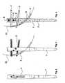
- FIGS. 1 to 8a first embodiment of a humeral nail with a nail shank 1, four serving as fixation elements 2 bone screws 2 and a stabilizing element 3 is shown.
- the nail shankis equipped in its proximal region 4 with a total of four holes 5 for fixing elements 2.
- the holes 5 in the proximal region of the nail shank 1are also referred to as proximal holes 5.
- Fix istsimplantation 2are arranged in all four holes.
- FIGS. 3, 4 and 5only two of the holes 5 are equipped with fixing elements 2.
- In the distal region 6 of the nail shank 1there are two further holes 7 for fixing elements. These holes are referred to as distal holes 7. In the drawing, the holes 7 are not provided with fixing elements.
- the holes 5 and 7are located at different positions of the nail shank. They are aligned at different angles to one another and to the longitudinal axis of the nail shank 1.
- the longitudinal axis of the nail shankis not shown in the drawing. It runs in the longitudinal direction of the nail shaft and forms its axis of symmetry. About this longitudinal axis of the nail shank is apart from the holes 5 and 7 and other openings and recesses rotationally symmetrical.
- FIGS. 15 and 16show the humeral nail together with a section of a humerus 9. In this illustration, the arrangement of the humeral nail in the humerus is recognizable.
- a passage opening 10 in the nail shaft into which the stabilizing element 3 is insertedIn addition to the bores 5 and 7 and the receptacle 8 there is a passage opening 10 in the nail shaft into which the stabilizing element 3 is inserted.
- the position of the passage openingis between the proximal bores 5 and the distal bores 7.
- the passage opening 10extends through the nail shank 1 and intersects the longitudinal axis. It has the same cross-section over its entire length.
- the course of the passage opening 10is represented by a curve. This curve is identical to the curve 22, which represents the course of the stabilization element 3.
- the curvepasses through the center or the center of the through hole and extends in the longitudinal direction of the entrance on one side of the nail shaft 1 to the exit of the through hole on the other side of the nail shank 1.
- the course of the curve 22is in the FIGS. 3 and 4 shown.
- the nail shaft 1is in FIG. 7 shown in different views.
- the right and left illustrationsshow a side view, with the plan view on the side in the left-hand illustration in the opposite direction as in the right-hand illustration.
- the nail shaft 1is rotated in the right-hand illustration relative to the left-hand representation by 180 °.
- the middle illustrationshows a longitudinal section through the nail shaft with the longitudinal axis lying in the cutting plane.
- the stabilizing element 3follows the course of the passage opening 10 and has the same curvature, which through the curve 22 in the FIGS. 3 and 4 is represented.
- a threaded boreis provided in the stabilizing element 3 as a receptacle 11. This is a threaded hole which completely penetrates the stabilizing element. It serves to receive one of the bone screws designed as fixing elements 2.
- the screw head facing away from the end of the fixing element 2is arranged in the threaded bore.
- the end region adjoining the receptacle 11has a wedge-shaped cutting edge 12. It facilitates the insertion of the stabilizing element into the bone of a patient and the insertion of the stabilizing element 3 into the passage opening 10 of the nail shaft 1.
- FIG. 8the stabilizing element is shown in different views.
- the right viewshows the elongated cross section 13 of the stabilizing element 3.
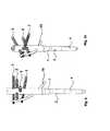
- FIGS. 9 to 15a second embodiment of a humeral nail is shown.
- the nail shaft 1 and the fixing elements 2are identical to the first embodiment. They are therefore provided with the same reference numbers.
- the second embodimentdiffers from the first embodiment in terms of the stabilizing element 14.
- the stabilizing element 14is longer than the stabilizing element 3 of the first embodiment.
- the stabilizing element 14has two receptacles 15 and 16 designed as threaded bores for fixing elements 2.
- a first receptacle 15is for the same fixing element 2 as the receptacle 11 of the stabilizing element 3 of the first embodiment.
- the second receptacle 16is provided immediately after the wedge-shaped cutting edge 17 of the stabilizing element 14. Both recordings 15 and 16 penetrate the stabilizing element. Due to the longer stabilizing element 14, an even higher stability of the supply of the humeral fracture is achieved.
- the course of the stabilizing element 14is represented by the same curve 22 as the profile of the stabilizing element 3 according to the first embodiment.
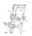
- FIG. 16shows a targeting device 18 for introducing a humeral nail into the humerus of a patient.
- the targeting device 18is shown in side view with a drill 19.
- the drill 19serves to drill a hole for a stabilizing element 3 or 14 in the humerus.
- the nail shaft 1 of a humeral nailis attached to a target arm 20 of the target device 18 via the receptacle 8.
- the recording 8 a Nagelschaftesis in the Figures 2 . 4 . 9 and 11 recognizable.
- FIG. 17shows the target device 18 in a perspective view with a guide sleeve 21 for a stabilizing element 14.
- the guide sleeve 21ensures that the stabilizing element 14 is inserted under the provided through the through hole 10 of the nail shank curvature in the humerus.
- the introduction of the stabilizing element 14is facilitated.
Landscapes
- Health & Medical Sciences (AREA)
- Surgery (AREA)
- Life Sciences & Earth Sciences (AREA)
- Orthopedic Medicine & Surgery (AREA)
- Biomedical Technology (AREA)
- Public Health (AREA)
- Veterinary Medicine (AREA)
- Engineering & Computer Science (AREA)
- Nuclear Medicine, Radiotherapy & Molecular Imaging (AREA)
- Heart & Thoracic Surgery (AREA)
- Medical Informatics (AREA)
- Molecular Biology (AREA)
- Animal Behavior & Ethology (AREA)
- General Health & Medical Sciences (AREA)
- Dentistry (AREA)
- Oral & Maxillofacial Surgery (AREA)
- Neurology (AREA)
- Surgical Instruments (AREA)
- Prostheses (AREA)
Description
Translated fromGermanDie Erfindung geht aus von einem Humerusnagel zur Versorgung von Frakturen des Humerus.The invention is based on a humeral nail for the treatment of fractures of the humerus.
Bei Frakturen des als Humerus bezeichneten Oberamknochens ist zumeist der Humeruskopf betroffen. Zur Versorgung derartiger Frakturen ist ein Marknagel vorgesehen, der aufgrund seines Anwendungsbereiches als Humerusnagel oder Humerusmarknagel bezeichnet wird. Humerusnägel werden am proximalen Ende des Humerus in den Röhrenknochen eingetrieben und durch mehrere Fixierungselemente im proximalen und/ oder distalen Bereich mit dem Knochen verbunden. Hierzu ist der Humerusnagel im proximalen und distalen Bereich mit Bohrungen ausgestattet. Diese können quer zur Längsachse des Nagelschaftes unter einem Winkel von 90° oder von weniger als 90° verlaufen. Die Bohrungen schneiden die Längsachse des Nagelschaftes an unterschiedlichen Positionen, da sie bezüglich der Längsachse versetzt angeordnet sind. Die Bohrachse oder Längsachse der Bohrungen verläuft unter demselben Winkel oder unter verschiedenen Winkeln zur Längsachse des Nagelschaftes des Humerusnagels. Ferner können die Bohrachsen je zweier Bohrungen parallel zueinander oder unter einem von 0° verschiedenen Winkel zueinander verlaufen. Als Fixierungselemente werden beispielsweise Knochenschrauben oder Knochenstifte verwendet. Die Fixierungselemente sollen dabei eine axiale Verschiebung des Humerusnagels verhindern und den Humerusnagel gegen Torsion sichern. Ein derartiger Humerusnagel ist beispielsweise aus der
Als nachteilig erweist sich bei den bekannten Humerusnägeln, dass bei einer frühen Mobilisierung des Patienten der mit einem Humerusnagel versorgte Humerus insbesondere im Bereich des Humeruskopfes und der Rotatorenmanschette den auftretenden Kräften nicht standhalten kann.A disadvantage of the known humeral nails proves that at an early mobilization of the patient supplied with a humeral nail humerus, especially in the area of the humeral head and the rotator cuff can not withstand the forces occurring.
Es ist daher Aufgabe der vorliegenden Erfindung, einen Humerusnagel zur Verfügung zu stellen, der eine frühe Mobilisierung des Patienten ermöglicht, indem die auf den Humerus einwirkenden Kräfte insbesondere im Bereich des Humeruskopfes und der Rotatorenmanschette abgefangen werden.It is therefore an object of the present invention to provide a humeral nail, which enables an early mobilization of the patient by intercepting the forces acting on the humerus, in particular in the region of the humeral head and the rotator cuff.
Diese Aufgabe wird durch einen erfindungsgemäßen Humerusnagel mit den Merkmalen des Anspruchs 1 gelöst. Der Humerusnagel zeichnet sich dadurch aus, dass zusätzlich zu den Bohrungen für Fixierungselemente eine Durchgangsöffnung im Nagelschaft vorgesehen ist. Diese Durchgangsöffnung dient zur Aufnahme eines zusätzlichen Stabilisierungselements. Dieses zusätzliche Stabilisierungselement ist von den stiftförmigen Fixierungselementen verschieden. Seine Länge ist typischerweise größer als die Länge der Fixierungselemente. Ein Ende des Stabilisierungselements weist bevorzugt mindestens eine Aufnahme für einen Abschnitt eines stiftförmigen Fixierungselements auf. Das Stabilisierungselement wird so weit durch die Durchgangsöffnung im Nagelschaft hindurch geschoben, dass ein in eine Bohrung des Nagelschaftes aufgenommenes Fixierungselement mit seinem einen Ende in der Aufnahme des Stabilisierungselements angeordnet ist. Damit bildet das durch die Durchgangsöffnung geführte Stabilisierungselement zusammen mit dem Fixierungselement eine zusätzliche Verstrebung des Humerusnagels.This object is achieved by a humeral nail according to the invention with the features of
Stabilisierungselement, Fixierungselement und Nagelschaft bilden ein Dreieck. Dabei kann die durch das Stabilisierungselement gebildete Seite auch gekrümmt sein. Durch die Verbindung zwischen dem Stabilisierungselement und dem Fixierungselement wird ein Verschieben des Stabilisierungselements in der Durchgangsöffnung verhindert. Das Stabilisierungselement sorgt dafür, dass die auf den Humeruskopf einwirkenden Kräfte abgefangen werden und die sekundäre Abkippung des Humeruskopfes vermieden wird. Dadurch wird eine zusätzliche Stabilisierung des Humerus erreicht. Eine frühe Mobilisierung des Patienten ist damit möglich.Das Stabilisierungselement weist einen gekrümmten Verlauf auf.Stabilizing element, fixing element and nail shank form a triangle. In this case, the side formed by the stabilization element can also be curved. By the connection between the stabilizing element and the fixing element, a displacement of the stabilizing element in the passage opening is prevented. The stabilizing element ensures that the forces acting on the humeral head are absorbed and the secondary tilting of the humeral head is avoided. This achieves additional stabilization of the humerus. An early mobilization of the patient is thus possible.The stabilizing element has a curved course.
Der Winkel, unter dem die Durchgangsöffnung bezüglich der Längsachse des Nagelschaftes verläuft, ist bevorzugt kleiner als 90°. Bei einem geradlinigen Verlauf der Durchgangsöffnung wird der Winkel zwischen einer durch den Verlauf vorgegebenen Geraden und der Längsachse bestimmt. Bei einem gekrümmten Verlauf der Durchgangsöffnung wird zur Bestimmung des Winkels an eine durch den Verlauf vorgegebene und die Längsachse schneidende Kurve eine Tangente angelegt. Die Tangente wird an die Kurve im Schnittpunkt mit der Längsachse angelegt. Anschließend wird der Winkel zwischen der Tangente und der Längsachse bestimmt.The angle at which the passage opening extends with respect to the longitudinal axis of the nail shank is preferably less than 90 °. In a straight-line course of the passage opening, the angle between a predetermined line through the course and the longitudinal axis is determined. In a curved course of the passage opening, a tangent is applied to determine the angle to a predetermined by the course and the longitudinal axis intersecting curve. The tangent is applied to the curve at the intersection with the longitudinal axis. Subsequently, the angle between the tangent and the longitudinal axis is determined.
Der Winkel, unter dem die Bohrung verläuft, welche mit einem in dem Stabilisierungselement aufgenommenen Fixierungselement ausgestattet ist, kann unter einem Winkel von 90° oder von weniger als 90° gegen die Längsachse des Nagelschaftes verlaufen.The angle at which the bore extends, which is equipped with a fixing element received in the stabilizing element, can run at an angle of 90 ° or less than 90 ° to the longitudinal axis of the nail shaft.
Bei der Aufnahme für ein Fixierungselement in dem Stabilisierungselement kann es sich beispielsweise um eine durchgängige oder nicht durchgängige Bohrung, eine Öffnung mit eckigem oder ovalem Querschnitt, eine Kerbe oder eine konische Vertiefung handeln.The receptacle for a fixing element in the stabilizing element may be, for example, a continuous or non-continuous bore, an opening with an angular or oval cross-section, a notch or a conical depression.
Die Bohrungen im Nagelschaft können frei von einem Gewinde sein oder mit einem Gewinde ausgestattet sein. Sofern sie mit einem Gewinde ausgestattet sind, ist dieses auf ein Gewinde der Fixierungselemente abgestimmt. In diesem Fall handelt es sich bei den Fixierungselementen um Knochenschrauben.The holes in the nail shank can be free of threads or threaded. Unless they are threaded are, this is tuned to a thread of the fixing elements. In this case, the fixation elements are bone screws.
Nach einer vorteilhaften Ausgestaltung der Erfindung verläuft die Durchgangsöffnung für das Stabilisierungselement zwischen den im proximalen Bereich vorgesehenen Bohrungen und dem distalen Ende des Nagelschaftes. Aufgrund einer Neigung der Durchgangsöffnung zur Längsachse des Nagelschaftes erstreckt sich ein durch die Durchgangsöffnung hindurch geführtes Stabilisierungselement mit seinem einen Ende bis in den Bereich der durch die Bohrungen im proximalen Bereich des Nagelschaftes eingesetzten Fixierungselemente. Das in die Durchgangsöffnung aufgenommene Stabilisierungselement bildet damit zusammen mit einem Fixierungselement eine Verbindung zwischen einem Abschnitt des Humerusnagels, der sich zwischen den proximalen Bohrungen und dem distalen Ende befindet, und dem proximalen Bereich des Humerusnagels.According to an advantageous embodiment of the invention, the passage opening for the stabilizing element extends between the holes provided in the proximal region and the distal end of the nail shank. Due to an inclination of the passage opening to the longitudinal axis of the nail shank, a stabilization element guided through the passage opening extends with its one end into the area of the fixing elements inserted through the holes in the proximal area of the nail shank. The stabilization element accommodated in the through opening thus forms together with a fixing element a connection between a section of the humeral nail located between the proximal bores and the distal end and the proximal region of the humeral nail.
Darüber hinaus kann die Durchgangsöffnung auch zwischen dem proximalen Ende des Nagelschaftes und den proximalen Bohrungen positioniert sein. Ferner besteht die Möglichkeit, die Durchgangsöffnung zwischen zwei der proximalen Bohrungen vorzusehen. Die Neigung der Durchgangsöffnung gegen die Längsachse des Nagelschaftes hängt dabei von der Position mindestens einer der Querborungen ab, wobei das in die Bohrung eingesetzte Fixierungselement mit dem Stabilisierungselement und dem Nagelschaft ein Dreieck bildet. Je kleiner der Abstand zwischen der Durchgangsöffnung und dieser Bohrung ist, um so größer ist der Winkel zwischen der Durchgangsöffnung und der Längsachse des Nagelschaftes und um so kleiner ist die durch einen Abschnitt des Nagelschaftes gebildete Seite des Dreiecks. Dabei wird davon ausgegangen, dass die Fixierungselemente eine vorgegebene Länge aufweisen und sich Fixierungselement und Stabilisierungselement an einer vorgegebenen Position kreuzen.In addition, the through-opening may also be positioned between the proximal end of the nail shaft and the proximal bores. It is also possible to provide the passage opening between two of the proximal bores. The inclination of the passage opening against the longitudinal axis of the nail shank depends on the position of at least one of the transverse mortars, wherein the fixing element inserted into the bore forms a triangle with the stabilizing element and the nail shank. The smaller the distance between the passage opening and this bore, the greater is the angle between the passage opening and the longitudinal axis of the nail shank and the smaller is the side of the triangle formed by a section of the nail shank. It is assumed that the fixing elements have a predetermined length and intersect fixing element and stabilizing element at a predetermined position.
Nach einer weiteren vorteilhaften Ausgestaltung der Erfindung weist die Durchgangsöffnung einen gekrümmten Verlauf auf. In eine derartige Durchgangsöffnung wird ein Stabilisierungselement eingesetzt, das ebenfalls gekrümmt ist, wobei der Verlauf der Krümmung qualitativ mit der Krümmung der Durchgangsöffnung übereinstimmt. Eine durch die Durchgangsöffnung in Längsrichtung zentrisch verlaufende Kurve stimmt darüber hinaus bevorzugt hinsichtlich ihres Verlaufs quantitativ mit einer entsprechenden Kurve durch das Stabilisierungselement überein. Durch die Krümmung wird erreicht, dass das Stabilisierungselement mit seinem einen Endbereich, welcher mit einer Aufnahme für ein Fixierungselement ausgestattet ist, einen kleineren Abstand zu dem Nagelschaft aufweist, als ein Stabilisierungselement mit geradlinigem Verlauf. Dadurch wird eine Stabilisierung des Humerus auf kleinerem Raum erzielt, als bei einem Stabilisierungselement mit geradlinigem Verlauf. Darüber hinaus können bei einer Durchgangsöffnung und einem Stabilisierungselement mit gekrümmtem Verlauf die Fixierungselemente eine geringere Länge aufweisen, da der Kreuzungspunkt von Stabilisierungselement und Fixierungselement näher am Nagelschaft liegt als bei einem geradlinig verlaufenden Stabilisierungselement. Darüber hinaus kann die Durchgangsöffnung auch einen geradlinigen Verlauf aufweisen. Vorteilhafterweise stimmt der Verlauf der Durchgangsöffnung qualitativ mit dem Verlauf des Stabilisierungselements überein. Dadurch wird das Stabilisierungselement durch die Durchgangsöffnung über die gesamte Länge der Durchgangsöffnung geführt und gestützt. Ist dagegen der Verlauf der Durchgangsöffnung geradlinig und der Verlauf des Stabilisierungselements gekrümmt, so findet nur eine Unterstützung an drei Punkten statt.According to a further advantageous embodiment of the invention, the passage opening on a curved course. In such a passage opening, a stabilizing element is used, which is also curved, wherein the course of the curvature qualitatively coincides with the curvature of the passage opening. Moreover, a curve extending centrally through the through-hole in the longitudinal direction preferably moreover agrees quantitatively with respect to its course with a corresponding curve through the stabilizing element. By the curvature is achieved that the stabilizing element with its one end region, which is equipped with a receptacle for a fixing element, a smaller distance from the nail shaft, as a stabilizing element with a straight course. This achieves stabilization of the humerus in a smaller space than with a straight-line stabilizing element. In addition, in the case of a passage opening and a stabilizing element with a curved course, the fixing elements may have a shorter length, since the point of intersection of stabilizing element and fixing element is closer to the nail shank than in the case of a rectilinear stabilizing element. In addition, the passage opening can also have a straight course. Advantageously, the course of the passage opening coincides qualitatively with the course of the stabilization element. As a result, the stabilizing element is guided and supported by the passage opening over the entire length of the passage opening. If, on the other hand, the course of the passage opening is rectilinear and the course of the stabilization element is curved, only support at three points takes place.
Nach einer weiteren vorteilhaften Ausgestaltung der Erfindung weist die Durchgangsöffnung über ihre gesamte Länge einen konstanten Querschnitt auf.According to a further advantageous embodiment of the invention, the through hole has a constant cross section over its entire length.
Entsprechendes gilt für das Stabilisierungselement, insbesondere für den Abschnitt, der durch die Durchgangsöffnung hindurch geführt wird.The same applies to the stabilizing element, in particular for the section which is guided through the passage opening.
Nach einer weiteren vorteilhaften Ausgestaltung der Erfindung weist die Durchgangsöffnung einen länglichen Querschnitt auf. Entsprechendes gilt bevorzugt für das Stabilisierungselement. Darüber hinaus weisen sowohl die Durchgangsöffnung als auch das Stabilisierungselement in ihren Querschnitten keine Ecken auf. Dies führt zu einer kantenfreien Außenkontur des Stabilisierungselements. Der längliche Querschnitt des Stabilisierungselementes sorgt zum einen für eine hohe Stabilität und bietet zum anderen ausreichend Platz beziehungsweise Raum für eine Aufnahme für eines oder mehrere Fixierungselemente.According to a further advantageous embodiment of the invention, the through hole has an elongated cross section. The same applies preferably to the stabilizing element. In addition, both the passage opening and the stabilizing element have no corners in their cross-sections. This leads to an edge-free outer contour of the stabilization element. The elongated cross-section of the stabilizing element ensures on the one hand for a high stability and on the other hand offers sufficient space or space for a receptacle for one or more fixing elements.
Nach einer weiteren vorteilhaften Ausgestaltung der Erfindung schneiden sich die Längsachse mindestens einer der Bohrungen einerseits und die Kurve, welche durch den Verlauf der Durchgangsöffnung vorgegeben ist, andererseits. Dies gilt sowohl für eine geradlinige Durchgangsöffnung als auch für eine Durchgangsöffnung mit gekrümmtem Verlauf. Der Schnittpunkt der Längsachse der Bohrung mit der durch die Durchgangsöffnung vorgegebene Kurve sorgt dafür, dass ein in die Durchgangsöffnung eingesetztes Stabilisierungselement und ein in eine Bohrung eingesetztes Fixierungselement einander berühren oder kreuzen.According to a further advantageous embodiment of the invention, the longitudinal axis intersect at least one of the holes on the one hand and the curve, which is predetermined by the course of the passage opening, on the other. This applies both to a rectilinear passage opening and to a passage opening with a curved course. The intersection of the longitudinal axis of the bore with the predetermined through the passage opening curve ensures that an inserted into the through hole stabilization element and a fixing element inserted into a bore touch or cross each other.
Nach einer weiteren vorteilhaften Ausgestaltung der Erfindung beträgt der Winkel der Durchgangsöffnung gegen die Längsachse des Nagelschaftes in bevorzugter Weise zwischen 10° und 60°. Bei einem gekrümmten Verlauf der Durchgangsöffnung entspricht dies dem Winkel zwischen einer im mittleren Abschnitt der Durchgangsöffnung an die Kontur angelegten Tangente und der Längsachse des Nagelschaftes.According to a further advantageous embodiment of the invention, the angle of the passage opening against the longitudinal axis of the nail shank in a preferred manner between 10 ° and 60 °. In the case of a curved course of the through opening, this corresponds to the angle between a tangent applied to the contour in the middle section of the passage opening and the longitudinal axis of the nail shank.
Nach einer weiteren vorteilhaften Ausgestaltung der Erfindung handelt es sich bei der Aufnahme in dem Stabilisierungselement um eine Bohrung mit oder ohne Gewinde. Im Falle einer Gewindebohrung ist das Gewinde auf ein Gewinde der Fixierungselemente abgestimmt. Eine als Gewindebohrung ausgebildete Aufnahme hat den Vorteil, dass das aufgenommene Fixierungselement auch in Richtung seiner Längsachse fixiert ist und nicht nur seitlich zur Längsachse.According to a further advantageous embodiment of the invention, the inclusion in the stabilizing element is a bore with or without thread. In the case of a threaded hole, the thread is matched to a thread of the fixing elements. A trained as a threaded receptacle has the advantage that the recorded fixing element is fixed in the direction of its longitudinal axis and not only laterally to the longitudinal axis.
Nach einer weiteren vorteilhaften Ausgestaltung der Erfindung befindet sich die Aufnahme an einem Ende des Stabilisierungselementes. Es handelt sich bevorzugt um eine durchgängige Bohrung, insbesondere um eine Gewindebohrung, oder um eine Öffnung. Sie erstreckt sich damit durch das Stabilisierungselement hindurch und kann somit einen möglichst großen Abschnitt eines Fixierungselements aufnehmen.According to a further advantageous embodiment of the invention, the receptacle is located at one end of the stabilizing element. It is preferably a continuous bore, in particular a threaded bore, or an opening. It thus extends through the stabilizing element and can thus accommodate the largest possible portion of a fixing element.
Nach einer weiteren vorteilhaften Ausgestaltung der Erfindung weist das Stabilisierungselement an dem diesem Ende abgewandten Endbereich einen Abschnitt auf, dessen Querschnitt größer ist, als der Querschnitt der Durchgangsöffnung. Dieser Abschnitt dient als Anschlag beim Einführen des Stabilisierungselements in die Durchgangsöffnung. Ist das Stabilisierungselement soweit durch die Durchgangsöffnung hindurch geschoben, dass der Abschnitt mit dem größerem Querschnitt am Nagelschaft anliegt, so ist ein weiteres Einschieben des Stabilisierungslementes verhindert. Dem Arzt wird beim Einsetzen dadurch angezeigt, dass das Stabiliserungselement bis zu der vorgesehenen Position vorgedrungen ist. In dieser Position kann die Aufnahme in dem Stabilisierungselement ein in eine Bohrung des Nagelschaftes eingesetztes Fixierungselement aufnehmen.According to a further advantageous embodiment of the invention, the stabilization element at the end region facing away from this end on a portion whose cross-section is larger than the cross section of the passage opening. This section serves as a stop when inserting the stabilizing element in the passage opening. If the stabilizing element pushed so far through the passage opening, that the portion with the larger cross-section rests on the nail shank, so further insertion of Stabilisierungslementes is prevented. The doctor is indicated during insertion by the fact that the stabilization element has penetrated to the intended position. In this position, the receptacle in the stabilizing element can receive a fixing element inserted into a bore of the nail shank.
Nach einer weiteren vorteilhaften Ausgestaltung der Erfindung ist das Stabilisierungselement mit einer keilförmigen Schneide ausgestattet. Die Schneide kann geschärft sein. Die keilförmige Schneide ist bevorzugt an einer Stirnseite des Stabilisierungselements angeordnet. Sie erleichtert das Eintreiben des Stabilisierungselements in den Knochen.According to a further advantageous embodiment of the invention, the stabilizing element is equipped with a wedge-shaped cutting edge. The cutting edge can be sharpened. The wedge-shaped cutting edge is preferably arranged on an end face of the stabilizing element. It facilitates the driving of the stabilizing element into the bone.
Weitere Vorteile und vorteilhafte Ausgestaltungen der Erfindung sind der nachfolgenden Beschreibung, der Zeichnung und den Ansprüchen zu entnehmen.Further advantages and advantageous embodiments of the invention will become apparent from the following description, the drawings and the claims.
In der Zeichnung sind zwei Ausführungsbeispiele eines erfindungsgemäßen Humerusnagels dargestellt. Es zeigen:
Figur 1- erstes Ausführungsbeispiel eines Humerusnagels mit kurzem Stabilisierungselement in einer Seitenansicht,
Figur 2Humerusnagel gemäß Figur 1 in perspektivischer Darstellung,Figur 3Humerusnagel gemäß Figur 1 mit zwei Knochenschrauben in Seitenansicht,- Figur 4
Humerusnagel gemäß Figur 3 im Längsschnitt,Figur 5Humerusnagel gemäß Figur 3 in einer um 90° gedrehten Seitenansicht,- Figur 6
Humerusnagel gemäß Figur 1 mit Humerus,Figur 7- Nagelschaft des Humerusnagels gemäß
Figur 1 in zwei Seitenansichten und einem Längsschnitt, Figur 8- Stabilisierungselement des Humerusnagels gemäß
Figur 1 in verschiedenen Ansichten und in Schnittdarstellung, Figur 9- zweites Ausführungsbeispiel eines Humerusnagels mit langem Stabilisierungselement in einer Seitenansicht,
Figur 10Humerusnagel gemäß Figur 9 in perspektivischer Darstellung,Figur 11Humerusnagel gemäß Figur 9 mit zwei Knochenschrauben in Seitenansicht,Figur 12Humerusnagel gemäß Figur 11 im Längsschnitt,Figur 13Humerusnagel gemäß Figur 11 in einer um 90° gedrehten Seitenansicht,Figur 14Humerusnagel gemäß Figur 9 mit Humerus,Figur 15- Stabilisierungselement des Humerusnagels gemäß
Figur 9 in verschiedenen Ansichten und in Schnittdarstellung, Figur 16- Zielgerät mit Bohrer in Seitenansicht,
Figur 17- Zielgerät mit Schutzhülse in perspektivischer Ansicht.
- FIG. 1
- first embodiment of a humeral nail with a short stabilizing element in a side view,
- FIG. 2
- Humeral nail according to
FIG. 1 in perspective, - FIG. 3
- Humeral nail according to
FIG. 1 with two bone screws in side view, - FIG. 4
- Humeral nail according to
FIG. 3 in longitudinal section, - FIG. 5
- Humeral nail according to
FIG. 3 in a 90 ° rotated side view, - FIG. 6
- Humeral nail according to
FIG. 1 with humerus, - FIG. 7
- Nail shaft of the humeral nail according to
FIG. 1 in two side views and a longitudinal section, - FIG. 8
- Stabilizing element of the humeral nail according to
FIG. 1 in different views and in section, - FIG. 9
- second embodiment of a humeral nail with a long stabilizing element in a side view,
- FIG. 10
- Humeral nail according to
FIG. 9 in perspective, - FIG. 11
- Humeral nail according to
FIG. 9 with two bone screws in side view, - FIG. 12
- Humeral nail according to
FIG. 11 in longitudinal section, - FIG. 13
- Humeral nail according to
FIG. 11 in a 90 ° rotated side view, - FIG. 14
- Humeral nail according to
FIG. 9 with humerus, - FIG. 15
- Stabilizing element of the humeral nail according to
FIG. 9 in different views and in section, - FIG. 16
- Targeting device with drill in side view,
- FIG. 17
- Target device with protective sleeve in perspective view.
In den
An dem proximalen Ende ist der Nagelschaft mit einer Aufnahme 8 für ein Zielgerät ausgestattet. Ein Zielgerät ist in den
Zusätzlich zu den Bohrungen 5 und 7 und der Aufnahme 8 befindet sich eine Durchgangsöffnung 10 in dem Nagelschaft, in welche das Stabilisierungselement 3 eingesetzt ist. Die Position der Durchgangsöffnung ist zwischen den proximalen Bohrungen 5 und den distalen Bohrungen 7. Die Durchgangsöffnung 10 erstreckt sich durch den Nagelschaft 1 hindurch und schneidet die Längsachse. Sie weist über ihre gesamte Länge denselben Querschnitt auf. Der Verlauf der Durchgangsöffnung 10 wird durch eine Kurve repräsentiert. Diese Kurve ist identisch mit der Kurve 22, die den Verlauf des Stabilisierungselements 3 repräsentiert. Die Kurve verläuft durch das Zentrum bzw. die Mitte der Durchgangsöffnung und erstreckt sich in Längsrichtung vom Eingang auf der einen Seite des Nagelschaftes 1 bis zum Ausgang der Durchgangsöffnung an der anderen Seite des Nagelschaftes 1. Der Verlauf der Kurve 22 ist in den
Der Nagelschaft 1 ist in
Das Stabilisierungselement 3 folgt dem Verlauf der Durchgangsöffnung 10 und weist dieselbe Krümmung auf, die durch die Kurve 22 in den
In
In den
Die
- 11
- Nagelschaftnail shaft
- 22
- Fixierungselementfixing element
- 33
- Stabilisierungselementstabilizing element
- 44
- proximaler Bereich des Nagelschaftesproximal area of the nail shaft
- 55
- proximale Bohrungproximal hole
- 66
- distaler Bereich des Nagelschaftesdistal area of the nail shaft
- 77
- distale Bohrungdistal bore
- 88th
- Aufnahme für ein WerkzeugRecording for a tool
- 99
- Humerushumerus
- 1010
- DurchgangsöffnungThrough opening
- 1111
- Aufnahmeadmission
- 1212
- keilförmige Schneidewedge-shaped edge
- 1313
- länglicher Querschnitt des Stabilisierungselementselongate cross-section of the stabilizing element
- 1414
- Stabilisierungselementstabilizing element
- 1515
- Aufnahmeadmission
- 1616
- Aufnahmeadmission
- 1717
- keilförmige Schneidewedge-shaped edge
- 1818
- Zielgerättarget device
- 1919
- Bohrerdrill
- 2020
- ZielarmTargeting Arm
- 2121
- Führungshülseguide sleeve
- 2222
- Verlauf des Stabilisierungselements des ersten AusführungsbeispielsCourse of the stabilizing element of the first embodiment
Claims (13)
- Humeral nail for caring for fractures of the humerus with an oblong nail shank (1),
with several holes (5) in the proximal area (4) for holding pin-shaped fixing elements (2),
with a through opening (10) in the nail shank (1) for holding a stabilising element (3, 14),
with a stabilising element (3, 14) for insertion in the through opening (10), with at least one support (11) in the stabilising element (3, 14) for a section of a fixing element (2) arranged in one of the holes (5) to connect the stabilising element (3, 14) with a fixing element (2),
characterised in that
the stabilising element (3, 14) has a curved course (22). - Humeral nail according to claim 1,characterised in that the through opening (10) runs through the nail shank between the holes (5) in the proximal area (4) and the distal end.
- Humeral nail according to claim 1 or 2,characterised in that the through opening (10) has a curved course (22).
- Humeral nail according to one of the previous claims,characterised in that the through opening (10) has a constant cross-section along its entire length.
- Humeral nail according to claim 4,characterised in that the cross-section of the through opening (10) is oblong.
- Humeral nail according to one of the previous claims,characterised in that the longitudinal axis of at least one of the holes (5) and a curve (22) specified by the course of the through opening (10) have a point of intersection.
- Humeral nail according to one of the previous claims,characterised in that the stabilising element (3, 14) is oblong.
- Humeral nail according to claim 3,characterised in that the course (22) of the stabilising element (3, 14) is consistent with the curved course of the through opening (10) in terms of quality.
- Humeral nail according to one of the previous claims,characterised in that the support (11) of the stabilising element (3, 14) is designed as a hole.
- Humeral nail according to one of the previous claims,characterised in that the support (11) is located in the area of an end of the stabilising element (3, 14).
- Humeral nail according to one of the previous claims,characterised in that the stabilising element (3, 14) has a section in the area of an end with a cross-section that is larger than the cross-section of the through opening.
- Humeral nail according to one of the previous claims,characterised in that the stabilising element (3, 14) has an oblong cross-section.
- Humeral nail according to one of the previous claims 12,characterised in that the stabilising element (3, 14) has a wedge-shaped edge (12) on one end.
Applications Claiming Priority (1)
| Application Number | Priority Date | Filing Date | Title |
|---|---|---|---|
| DE102009010328ADE102009010328A1 (en) | 2009-02-25 | 2009-02-25 | Humerus nail for supporting fractures of humerus of patient, has retainer provided in stabilization element to retain section of fixing elements arranged in one of boreholes for connecting stabilization element with fixing elements |
Publications (2)
| Publication Number | Publication Date |
|---|---|
| EP2258290A1 EP2258290A1 (en) | 2010-12-08 |
| EP2258290B1true EP2258290B1 (en) | 2013-07-31 |
Family
ID=42356728
Family Applications (1)
| Application Number | Title | Priority Date | Filing Date |
|---|---|---|---|
| EP10001409.1AActiveEP2258290B1 (en) | 2009-02-25 | 2010-02-11 | Humeral nail for humerus fractures |
Country Status (3)
| Country | Link |
|---|---|
| EP (1) | EP2258290B1 (en) |
| DE (1) | DE102009010328A1 (en) |
| ES (1) | ES2432389T3 (en) |
Families Citing this family (4)
| Publication number | Priority date | Publication date | Assignee | Title |
|---|---|---|---|---|
| EP3273889B1 (en)* | 2015-03-25 | 2020-12-02 | Pier Giovanni Menci | Intramedullary nail for the treatment of fractures of long bones |
| US11083503B2 (en) | 2016-09-22 | 2021-08-10 | Globus Medical, Inc. | Systems and methods for intramedullary nail implantation |
| US10492803B2 (en) | 2016-09-22 | 2019-12-03 | Globus Medical, Inc. | Systems and methods for intramedullary nail implantation |
| US11633219B2 (en) | 2019-06-26 | 2023-04-25 | Globus Medical, Inc. | Fenestrated pedicle nail |
Citations (1)
| Publication number | Priority date | Publication date | Assignee | Title |
|---|---|---|---|---|
| FR2781360A1 (en)* | 1998-07-23 | 2000-01-28 | Raymond Massaad | Bone nail fixing for surgery has plate with angled bore for clamping screw and end stop |
Family Cites Families (14)
| Publication number | Priority date | Publication date | Assignee | Title |
|---|---|---|---|---|
| IL22711A (en)* | 1965-01-01 | 1968-04-25 | Salama R | Nail plate for trochanteric fractures of the femur |
| DE8712991U1 (en)* | 1987-09-26 | 1987-11-05 | Kernforschungszentrum Karlsruhe Gmbh, 7500 Karlsruhe | Nail for fixation of proximal femoral fractures |
| DE8812157U1 (en)* | 1988-09-26 | 1988-11-10 | Waldemar Link Gmbh & Co, 2000 Hamburg | Bone-supporting implant |
| US5032125A (en)* | 1990-02-06 | 1991-07-16 | Smith & Nephew Richards Inc. | Intramedullary hip screw |
| DE19806323A1 (en)* | 1997-11-12 | 1999-05-20 | Artos Med Produkte | Bone marrow-pin system used in osteosynthesis |
| DE29907161U1 (en)* | 1999-04-22 | 2000-08-24 | Wischhöfer, Edlef, Prof. Dr. Dr.med., 85092 Kösching | Blocking plate for osteosynthesis on the humerus |
| JP4278289B2 (en)* | 2000-07-27 | 2009-06-10 | 有限会社ケイオーアイ | Intramedullary nail |
| ATE303765T1 (en)* | 2002-04-18 | 2005-09-15 | Zimmer Gmbh | BONE FIXATION SYSTEM |
| DE20213166U1 (en) | 2002-08-28 | 2004-01-08 | Stryker Trauma Gmbh | humeral |
| EP1572017A1 (en) | 2002-11-13 | 2005-09-14 | Orthoplex LLC | Anchoring system for fixing objects to bones |
| WO2005092219A1 (en)* | 2004-03-26 | 2005-10-06 | Hirotaka Shimizu | Bone connecting tool |
| US20070123876A1 (en)* | 2005-10-31 | 2007-05-31 | Czartoski Timothy J | Multiple purpose nail, nail assembly and associated method |
| ES2251888B1 (en)* | 2005-11-08 | 2007-04-01 | Carlos Enrique Morales Berenguer | DELTA DEVICE FOR THE TREATMENT OF TROCANTERIC AND SUBTOCANTERIC FRACTURES OF FEMUR. |
| JP2009530035A (en)* | 2006-03-20 | 2009-08-27 | スミス アンド ネフュー インコーポレーテッド | Assembly consisting of shaping plate and screw |
- 2009
- 2009-02-25DEDE102009010328Apatent/DE102009010328A1/ennot_activeWithdrawn
- 2010
- 2010-02-11ESES10001409Tpatent/ES2432389T3/enactiveActive
- 2010-02-11EPEP10001409.1Apatent/EP2258290B1/enactiveActive
Patent Citations (1)
| Publication number | Priority date | Publication date | Assignee | Title |
|---|---|---|---|---|
| FR2781360A1 (en)* | 1998-07-23 | 2000-01-28 | Raymond Massaad | Bone nail fixing for surgery has plate with angled bore for clamping screw and end stop |
Also Published As
| Publication number | Publication date |
|---|---|
| DE102009010328A1 (en) | 2010-08-26 |
| EP2258290A1 (en) | 2010-12-08 |
| ES2432389T3 (en) | 2013-12-03 |
Similar Documents
| Publication | Publication Date | Title |
|---|---|---|
| DE4318150C2 (en) | Osteosynthesis tools for the treatment of subtrochanteric and pertrochanteric fractures as well as fractures of the femoral neck | |
| EP1059888B1 (en) | Intramedullary nail with locking hole | |
| EP1233712B1 (en) | Intramedullary nail | |
| EP1658013B1 (en) | Intramedullary nail | |
| EP1402831B1 (en) | Humerus nail | |
| EP2892451B1 (en) | Pelvic ring implant | |
| DE60119890T2 (en) | HAND FIXING DEVICE | |
| EP0561295B1 (en) | Externally fastened intramedullary nail | |
| AT507271B1 (en) | KNOCHENSCHRAUBENSET | |
| EP1830727B1 (en) | Intramedullary nail | |
| DE20110948U1 (en) | Surgical instrument | |
| DE29615482U1 (en) | Supracondylar bone nail | |
| DE2716403A1 (en) | DEVICE FOR SETTING BONE BREAKS | |
| DE9115200U1 (en) | Locking nail for the treatment of fractures of the long bones | |
| DE3729840C1 (en) | Medullary cavity - locking nail | |
| EP2258290B1 (en) | Humeral nail for humerus fractures | |
| EP2476388A1 (en) | Osteosynthesis plate, in particular radius plate or ulnar plate, for stabilising bone fractures | |
| DE20113345U1 (en) | Femurfrakturnagel | |
| EP1180980B1 (en) | Intramedullary nail for the tibia | |
| DE19703987C1 (en) | Target device for an implant to treat trochanteric and subtrochanteric fractures | |
| EP1643917A1 (en) | Aiming device | |
| EP1648318B1 (en) | Device for fixing a longitudinal carrier to a bone fixing element | |
| WO2002080790A1 (en) | Bone nail for surgical purposes | |
| DE102007029090A1 (en) | Device for osteosynthesis, particularly bone fracture near joint, has pin for implantation into abarticular bone, and proximal longitudinal ring element provided for implantation into bone fragment near joint | |
| DE202004018748U1 (en) | Intramedullary nail in particular to be used in femur, comprising various differently shaped openings and grooves for adding more nails or screws |
Legal Events
| Date | Code | Title | Description |
|---|---|---|---|
| PUAI | Public reference made under article 153(3) epc to a published international application that has entered the european phase | Free format text:ORIGINAL CODE: 0009012 | |
| AK | Designated contracting states | Kind code of ref document:A1 Designated state(s):AT BE BG CH CY CZ DE DK EE ES FI FR GB GR HR HU IE IS IT LI LT LU LV MC MK MT NL NO PL PT RO SE SI SK SM TR | |
| AX | Request for extension of the european patent | Extension state:AL BA RS | |
| 17P | Request for examination filed | Effective date:20110210 | |
| 17Q | First examination report despatched | Effective date:20120706 | |
| GRAP | Despatch of communication of intention to grant a patent | Free format text:ORIGINAL CODE: EPIDOSNIGR1 | |
| INTG | Intention to grant announced | Effective date:20130402 | |
| GRAS | Grant fee paid | Free format text:ORIGINAL CODE: EPIDOSNIGR3 | |
| GRAA | (expected) grant | Free format text:ORIGINAL CODE: 0009210 | |
| AK | Designated contracting states | Kind code of ref document:B1 Designated state(s):AT BE BG CH CY CZ DE DK EE ES FI FR GB GR HR HU IE IS IT LI LT LU LV MC MK MT NL NO PL PT RO SE SI SK SM TR | |
| REG | Reference to a national code | Ref country code:GB Ref legal event code:FG4D Free format text:NOT ENGLISH Ref country code:CH Ref legal event code:EP | |
| REG | Reference to a national code | Ref country code:AT Ref legal event code:REF Ref document number:624151 Country of ref document:AT Kind code of ref document:T Effective date:20130815 | |
| REG | Reference to a national code | Ref country code:IE Ref legal event code:FG4D Free format text:LANGUAGE OF EP DOCUMENT: GERMAN | |
| REG | Reference to a national code | Ref country code:DE Ref legal event code:R096 Ref document number:502010004175 Country of ref document:DE Effective date:20130926 | |
| REG | Reference to a national code | Ref country code:NL Ref legal event code:VDEP Effective date:20130731 | |
| REG | Reference to a national code | Ref country code:LT Ref legal event code:MG4D | |
| PG25 | Lapsed in a contracting state [announced via postgrant information from national office to epo] | Ref country code:CY Free format text:LAPSE BECAUSE OF FAILURE TO SUBMIT A TRANSLATION OF THE DESCRIPTION OR TO PAY THE FEE WITHIN THE PRESCRIBED TIME-LIMIT Effective date:20130911 Ref country code:NO Free format text:LAPSE BECAUSE OF FAILURE TO SUBMIT A TRANSLATION OF THE DESCRIPTION OR TO PAY THE FEE WITHIN THE PRESCRIBED TIME-LIMIT Effective date:20131031 Ref country code:HR Free format text:LAPSE BECAUSE OF FAILURE TO SUBMIT A TRANSLATION OF THE DESCRIPTION OR TO PAY THE FEE WITHIN THE PRESCRIBED TIME-LIMIT Effective date:20130731 Ref country code:LT Free format text:LAPSE BECAUSE OF FAILURE TO SUBMIT A TRANSLATION OF THE DESCRIPTION OR TO PAY THE FEE WITHIN THE PRESCRIBED TIME-LIMIT Effective date:20130731 Ref country code:PT Free format text:LAPSE BECAUSE OF FAILURE TO SUBMIT A TRANSLATION OF THE DESCRIPTION OR TO PAY THE FEE WITHIN THE PRESCRIBED TIME-LIMIT Effective date:20131202 Ref country code:SE Free format text:LAPSE BECAUSE OF FAILURE TO SUBMIT A TRANSLATION OF THE DESCRIPTION OR TO PAY THE FEE WITHIN THE PRESCRIBED TIME-LIMIT Effective date:20130731 Ref country code:IS Free format text:LAPSE BECAUSE OF FAILURE TO SUBMIT A TRANSLATION OF THE DESCRIPTION OR TO PAY THE FEE WITHIN THE PRESCRIBED TIME-LIMIT Effective date:20131130 | |
| PG25 | Lapsed in a contracting state [announced via postgrant information from national office to epo] | Ref country code:NL Free format text:LAPSE BECAUSE OF FAILURE TO SUBMIT A TRANSLATION OF THE DESCRIPTION OR TO PAY THE FEE WITHIN THE PRESCRIBED TIME-LIMIT Effective date:20130731 Ref country code:FI Free format text:LAPSE BECAUSE OF FAILURE TO SUBMIT A TRANSLATION OF THE DESCRIPTION OR TO PAY THE FEE WITHIN THE PRESCRIBED TIME-LIMIT Effective date:20130731 Ref country code:LV Free format text:LAPSE BECAUSE OF FAILURE TO SUBMIT A TRANSLATION OF THE DESCRIPTION OR TO PAY THE FEE WITHIN THE PRESCRIBED TIME-LIMIT Effective date:20130731 Ref country code:PL Free format text:LAPSE BECAUSE OF FAILURE TO SUBMIT A TRANSLATION OF THE DESCRIPTION OR TO PAY THE FEE WITHIN THE PRESCRIBED TIME-LIMIT Effective date:20130731 Ref country code:SI Free format text:LAPSE BECAUSE OF FAILURE TO SUBMIT A TRANSLATION OF THE DESCRIPTION OR TO PAY THE FEE WITHIN THE PRESCRIBED TIME-LIMIT Effective date:20130731 Ref country code:GR Free format text:LAPSE BECAUSE OF FAILURE TO SUBMIT A TRANSLATION OF THE DESCRIPTION OR TO PAY THE FEE WITHIN THE PRESCRIBED TIME-LIMIT Effective date:20131101 | |
| PG25 | Lapsed in a contracting state [announced via postgrant information from national office to epo] | Ref country code:CY Free format text:LAPSE BECAUSE OF FAILURE TO SUBMIT A TRANSLATION OF THE DESCRIPTION OR TO PAY THE FEE WITHIN THE PRESCRIBED TIME-LIMIT Effective date:20130731 | |
| PG25 | Lapsed in a contracting state [announced via postgrant information from national office to epo] | Ref country code:RO Free format text:LAPSE BECAUSE OF FAILURE TO SUBMIT A TRANSLATION OF THE DESCRIPTION OR TO PAY THE FEE WITHIN THE PRESCRIBED TIME-LIMIT Effective date:20130731 Ref country code:CZ Free format text:LAPSE BECAUSE OF FAILURE TO SUBMIT A TRANSLATION OF THE DESCRIPTION OR TO PAY THE FEE WITHIN THE PRESCRIBED TIME-LIMIT Effective date:20130731 Ref country code:DK Free format text:LAPSE BECAUSE OF FAILURE TO SUBMIT A TRANSLATION OF THE DESCRIPTION OR TO PAY THE FEE WITHIN THE PRESCRIBED TIME-LIMIT Effective date:20130731 Ref country code:EE Free format text:LAPSE BECAUSE OF FAILURE TO SUBMIT A TRANSLATION OF THE DESCRIPTION OR TO PAY THE FEE WITHIN THE PRESCRIBED TIME-LIMIT Effective date:20130731 Ref country code:SK Free format text:LAPSE BECAUSE OF FAILURE TO SUBMIT A TRANSLATION OF THE DESCRIPTION OR TO PAY THE FEE WITHIN THE PRESCRIBED TIME-LIMIT Effective date:20130731 | |
| PGFP | Annual fee paid to national office [announced via postgrant information from national office to epo] | Ref country code:DE Payment date:20140220 Year of fee payment:5 | |
| PLBE | No opposition filed within time limit | Free format text:ORIGINAL CODE: 0009261 | |
| STAA | Information on the status of an ep patent application or granted ep patent | Free format text:STATUS: NO OPPOSITION FILED WITHIN TIME LIMIT | |
| 26N | No opposition filed | Effective date:20140502 | |
| REG | Reference to a national code | Ref country code:DE Ref legal event code:R097 Ref document number:502010004175 Country of ref document:DE Effective date:20140502 | |
| BERE | Be: lapsed | Owner name:DIETER MARQUARDT MEDIZINTECHNIK G.M.B.H. Effective date:20140228 | |
| PG25 | Lapsed in a contracting state [announced via postgrant information from national office to epo] | Ref country code:LU Free format text:LAPSE BECAUSE OF FAILURE TO SUBMIT A TRANSLATION OF THE DESCRIPTION OR TO PAY THE FEE WITHIN THE PRESCRIBED TIME-LIMIT Effective date:20140211 Ref country code:MC Free format text:LAPSE BECAUSE OF FAILURE TO SUBMIT A TRANSLATION OF THE DESCRIPTION OR TO PAY THE FEE WITHIN THE PRESCRIBED TIME-LIMIT Effective date:20130731 | |
| REG | Reference to a national code | Ref country code:CH Ref legal event code:PL | |
| PG25 | Lapsed in a contracting state [announced via postgrant information from national office to epo] | Ref country code:LI Free format text:LAPSE BECAUSE OF NON-PAYMENT OF DUE FEES Effective date:20140228 Ref country code:CH Free format text:LAPSE BECAUSE OF NON-PAYMENT OF DUE FEES Effective date:20140228 | |
| REG | Reference to a national code | Ref country code:IE Ref legal event code:MM4A | |
| PG25 | Lapsed in a contracting state [announced via postgrant information from national office to epo] | Ref country code:IE Free format text:LAPSE BECAUSE OF NON-PAYMENT OF DUE FEES Effective date:20140211 Ref country code:BE Free format text:LAPSE BECAUSE OF NON-PAYMENT OF DUE FEES Effective date:20140228 | |
| REG | Reference to a national code | Ref country code:DE Ref legal event code:R119 Ref document number:502010004175 Country of ref document:DE | |
| PG25 | Lapsed in a contracting state [announced via postgrant information from national office to epo] | Ref country code:DE Free format text:LAPSE BECAUSE OF NON-PAYMENT OF DUE FEES Effective date:20150901 | |
| REG | Reference to a national code | Ref country code:FR Ref legal event code:PLFP Year of fee payment:7 | |
| PG25 | Lapsed in a contracting state [announced via postgrant information from national office to epo] | Ref country code:MT Free format text:LAPSE BECAUSE OF FAILURE TO SUBMIT A TRANSLATION OF THE DESCRIPTION OR TO PAY THE FEE WITHIN THE PRESCRIBED TIME-LIMIT Effective date:20130731 | |
| REG | Reference to a national code | Ref country code:AT Ref legal event code:MM01 Ref document number:624151 Country of ref document:AT Kind code of ref document:T Effective date:20150211 | |
| PG25 | Lapsed in a contracting state [announced via postgrant information from national office to epo] | Ref country code:SM Free format text:LAPSE BECAUSE OF FAILURE TO SUBMIT A TRANSLATION OF THE DESCRIPTION OR TO PAY THE FEE WITHIN THE PRESCRIBED TIME-LIMIT Effective date:20130731 | |
| PG25 | Lapsed in a contracting state [announced via postgrant information from national office to epo] | Ref country code:AT Free format text:LAPSE BECAUSE OF NON-PAYMENT OF DUE FEES Effective date:20150211 | |
| PG25 | Lapsed in a contracting state [announced via postgrant information from national office to epo] | Ref country code:BG Free format text:LAPSE BECAUSE OF FAILURE TO SUBMIT A TRANSLATION OF THE DESCRIPTION OR TO PAY THE FEE WITHIN THE PRESCRIBED TIME-LIMIT Effective date:20130731 | |
| PG25 | Lapsed in a contracting state [announced via postgrant information from national office to epo] | Ref country code:HU Free format text:LAPSE BECAUSE OF FAILURE TO SUBMIT A TRANSLATION OF THE DESCRIPTION OR TO PAY THE FEE WITHIN THE PRESCRIBED TIME-LIMIT; INVALID AB INITIO Effective date:20100211 Ref country code:TR Free format text:LAPSE BECAUSE OF FAILURE TO SUBMIT A TRANSLATION OF THE DESCRIPTION OR TO PAY THE FEE WITHIN THE PRESCRIBED TIME-LIMIT Effective date:20130731 | |
| REG | Reference to a national code | Ref country code:FR Ref legal event code:PLFP Year of fee payment:8 | |
| REG | Reference to a national code | Ref country code:FR Ref legal event code:PLFP Year of fee payment:9 | |
| PG25 | Lapsed in a contracting state [announced via postgrant information from national office to epo] | Ref country code:MK Free format text:LAPSE BECAUSE OF FAILURE TO SUBMIT A TRANSLATION OF THE DESCRIPTION OR TO PAY THE FEE WITHIN THE PRESCRIBED TIME-LIMIT Effective date:20130731 | |
| P01 | Opt-out of the competence of the unified patent court (upc) registered | Effective date:20230513 | |
| PGFP | Annual fee paid to national office [announced via postgrant information from national office to epo] | Ref country code:ES Payment date:20250318 Year of fee payment:16 | |
| PGFP | Annual fee paid to national office [announced via postgrant information from national office to epo] | Ref country code:FR Payment date:20250219 Year of fee payment:16 | |
| PGFP | Annual fee paid to national office [announced via postgrant information from national office to epo] | Ref country code:IT Payment date:20250228 Year of fee payment:16 Ref country code:GB Payment date:20250220 Year of fee payment:16 |