EP2258286A2 - Device for accessing a body cavity - Google Patents
Device for accessing a body cavityDownload PDFInfo
- Publication number
- EP2258286A2 EP2258286A2EP10011045AEP10011045AEP2258286A2EP 2258286 A2EP2258286 A2EP 2258286A2EP 10011045 AEP10011045 AEP 10011045AEP 10011045 AEP10011045 AEP 10011045AEP 2258286 A2EP2258286 A2EP 2258286A2
- Authority
- EP
- European Patent Office
- Prior art keywords
- sleeve
- distal
- assembly
- tubular member
- region
- Prior art date
- Legal status (The legal status is an assumption and is not a legal conclusion. Google has not performed a legal analysis and makes no representation as to the accuracy of the status listed.)
- Withdrawn
Links
- 238000007789sealingMethods0.000claimsdescription16
- 230000003187abdominal effectEffects0.000claimsdescription11
- 230000007246mechanismEffects0.000claimsdescription7
- 210000001113umbilicusAnatomy0.000claimsdescription6
- 229920001971elastomerPolymers0.000claimsdescription3
- 239000000806elastomerSubstances0.000claimsdescription3
- 210000003815abdominal wallAnatomy0.000description34
- 238000000034methodMethods0.000description33
- 210000001015abdomenAnatomy0.000description15
- 230000035515penetrationEffects0.000description13
- 238000001356surgical procedureMethods0.000description12
- 210000001519tissueAnatomy0.000description12
- 239000000463materialSubstances0.000description8
- 210000000056organAnatomy0.000description6
- 208000005646PneumoperitoneumDiseases0.000description5
- 230000002093peripheral effectEffects0.000description5
- 229920000642polymerPolymers0.000description5
- CURLTUGMZLYLDI-UHFFFAOYSA-NCarbon dioxideChemical compoundO=C=OCURLTUGMZLYLDI-UHFFFAOYSA-N0.000description4
- 210000000683abdominal cavityAnatomy0.000description4
- 210000003195fasciaAnatomy0.000description4
- 208000014674injuryDiseases0.000description4
- 210000004303peritoneumAnatomy0.000description4
- 230000006835compressionEffects0.000description3
- 238000007906compressionMethods0.000description3
- 238000003780insertionMethods0.000description3
- 230000037431insertionEffects0.000description3
- 239000012528membraneSubstances0.000description3
- 230000008733traumaEffects0.000description3
- 208000027418Wounds and injuryDiseases0.000description2
- 230000004913activationEffects0.000description2
- 239000000853adhesiveSubstances0.000description2
- 230000001070adhesive effectEffects0.000description2
- 230000008901benefitEffects0.000description2
- 229910002092carbon dioxideInorganic materials0.000description2
- 239000001569carbon dioxideSubstances0.000description2
- 238000013461designMethods0.000description2
- 238000002357laparoscopic surgeryMethods0.000description2
- 238000002350laparotomyMethods0.000description2
- 210000004379membraneAnatomy0.000description2
- 230000004048modificationEffects0.000description2
- 238000012986modificationMethods0.000description2
- 210000003200peritoneal cavityAnatomy0.000description2
- -1polypropylenePolymers0.000description2
- 229920000571Nylon 11Polymers0.000description1
- 239000004698PolyethyleneSubstances0.000description1
- 239000004743PolypropyleneSubstances0.000description1
- 229920004738ULTEM®Polymers0.000description1
- 210000003484anatomyAnatomy0.000description1
- 238000004873anchoringMethods0.000description1
- 239000008280bloodSubstances0.000description1
- 210000004369bloodAnatomy0.000description1
- 239000002131composite materialSubstances0.000description1
- 230000006378damageEffects0.000description1
- 238000005516engineering processMethods0.000description1
- 210000000936intestineAnatomy0.000description1
- 229920000126latexPolymers0.000description1
- 239000004816latexSubstances0.000description1
- 210000004185liverAnatomy0.000description1
- 238000002324minimally invasive surgeryMethods0.000description1
- 238000012978minimally invasive surgical procedureMethods0.000description1
- 210000003205muscleAnatomy0.000description1
- 229920000573polyethylenePolymers0.000description1
- 229920000139polyethylene terephthalatePolymers0.000description1
- 239000005020polyethylene terephthalateSubstances0.000description1
- 229920001155polypropylenePolymers0.000description1
- 229920001296polysiloxanePolymers0.000description1
- 230000008569processEffects0.000description1
- 229910001220stainless steelInorganic materials0.000description1
- 239000010935stainless steelSubstances0.000description1
- 210000002784stomachAnatomy0.000description1
- 229920002725thermoplastic elastomerPolymers0.000description1
- 230000000451tissue damageEffects0.000description1
- 231100000827tissue damageToxicity0.000description1
- 230000000472traumatic effectEffects0.000description1
- 230000003144traumatizing effectEffects0.000description1
- 210000004291uterusAnatomy0.000description1
- 210000001835visceraAnatomy0.000description1
- 230000000007visual effectEffects0.000description1
- 238000012800visualizationMethods0.000description1
Images


Classifications
- A—HUMAN NECESSITIES
- A61—MEDICAL OR VETERINARY SCIENCE; HYGIENE
- A61B—DIAGNOSIS; SURGERY; IDENTIFICATION
- A61B17/00—Surgical instruments, devices or methods
- A61B17/34—Trocars; Puncturing needles
- A61B17/3417—Details of tips or shafts, e.g. grooves, expandable, bendable; Multiple coaxial sliding cannulas, e.g. for dilating
- A61B2017/3419—Sealing means between cannula and body
- A—HUMAN NECESSITIES
- A61—MEDICAL OR VETERINARY SCIENCE; HYGIENE
- A61B—DIAGNOSIS; SURGERY; IDENTIFICATION
- A61B17/00—Surgical instruments, devices or methods
- A61B17/34—Trocars; Puncturing needles
- A61B2017/348—Means for supporting the trocar against the body or retaining the trocar inside the body
- A61B2017/3482—Means for supporting the trocar against the body or retaining the trocar inside the body inside
- A61B2017/3484—Anchoring means, e.g. spreading-out umbrella-like structure
- A—HUMAN NECESSITIES
- A61—MEDICAL OR VETERINARY SCIENCE; HYGIENE
- A61B—DIAGNOSIS; SURGERY; IDENTIFICATION
- A61B17/00—Surgical instruments, devices or methods
- A61B17/34—Trocars; Puncturing needles
- A61B2017/348—Means for supporting the trocar against the body or retaining the trocar inside the body
- A61B2017/3492—Means for supporting the trocar against the body or retaining the trocar inside the body against the outside of the body
Definitions
- the present inventionrelates generally to devices and methods for introducing medical instruments into the abdomen.
- the present inventionrelates to an abdominal access assembly having an expandable anchor to secure and seal the access assembly to the abdominal wall of the patient.
- Minimally invasive surgical procedureshave recently been developed as alternatives to conventional "open” surgery.
- Minimally invasive proceduressuch as laparoscopy, involve accessing the surgical area inside a patient through a plurality of ports created in the patient's body. This type of procedure is generally less traumatic to the body than open surgery and since these ports tend to cause less tissue damage and blood loss as compared to cuts made on the body for open surgery.
- the abdominal wallmust be elevated from the organs in the intra-abdominal cavity for typical endoscopic or laparoscopic procedures. This is usually accomplished by filling the cavity with a gas, such as carbon dioxide, to inflate the cavity.
- a gassuch as carbon dioxide
- insufflationis typically achieved by inserting a large-gauge needle known as a Veress needle into the intra-abdominal cavity for the introduction of gas.
- Veress needlea large-gauge needle
- the insufflationmust be maintained, as the abdominal wall must remain elevated from the organs in the intra-abdominal cavity.
- the cavityis accessed by inserting a trocar and cannula assembly through the abdominal wall.
- the trocaris sharp stylet used to provide an initial penetration and access opening in the abdominal wall for the cannula.
- Introduction of the trocarcan present significant risk to the patient, especially the first opening which is performed blind, i.e. prior to introduction of the laparoscope.
- the risksstem from possible excessive penetration by the trocar causing injury to underlying internal organs.
- the riskis exacerbated by the toughness and elasticity of the abdominal wall which require substantial manual force for trocar penetration.
- an alternative method known as the "open laparoscopy” method or the Hasson methodexists for establishing access openings without the use of a sharp trocar.
- accesscan be established to the peritoneal cavity through a small incision on the skin of the abdomen, typically through the umbilicus. Continuous visual control is maintained for insertion of a special open laparoscopic cannula.
- the physicianuses standard laparotomy instruments and grasping forceps to laterally enlarge the initial incision and to lift/separate the fascia. This procedure eventually exposes the peritoneum and places it under tension so that it can be carefully pierced.
- the physiciancan pass a gloved finger into the cavity accessing the relevant anatomy and confirming safe entry.
- the physiciancan insert the cannula with a blunt dilator through the mini-laparotomy and continue with a standard laparoscopic procedure.
- the coneis usually sutured to the skin at a depth and position where the tissue's resiliency provides sufficient compression to maintain a seal.
- the conemay be anchored to the skin by other devices such as adhesives, skin staples or spring clips.
- Another device to maintain the integrity of the gas sealemploys an inflatable membrane at the insertable end of the cannula and securely positions the cannula by capturing a patient's tissue between a sealing sleeve and the inflatable membrane.
- U.S. Patent Nos. 5,002,557 and 5,176,697disclose a laparoscopic cannula having an inflatable anchor.
- U.S. Patent Nos. 4,496,345 ; 5,209,754 ; and 5,540,658show transcervical devices having expandable anchors for either maneuvering or securing the uterus.
- a device for mounting a cannula to a body of a patientis disclosed in U.S. Patent No. 5,267,970 .
- U.S. Patent No. 4,617,933shows a laparoscope cannula with improved suture receiving means.
- a cannula having a Malecot structure at a distal end of the cannula to prevent retractionis described in U.S. Patent No. 5,454,790 .
- the present inventionis directed at devices and methods capable of providing a gas seal against a penetration in the abdominal wall without the use of suturing, external adhesive devices, or an inflatable anchor.
- the device of the present inventiongenerally has an expandable anchor designed to prevent withdrawal of an abdominal access device such as a cannula while maintaining pneumoperitoneum in the abdominal cavity.
- the anchoris integrated into the device design, will not, rupture, and does not traumatize the body tissue against which it anchors.
- the device of the present inventionis an abdominal access assembly comprising a tubular member, a first sleeve, a pneumostasis valve, and a blunt obturator.
- the tubular memberhas a proximal end, a distal end, and a lumen therethrough.
- the first sleeveis disposed coaxially over the tubular member and has a distal radially expandable region and a proximal non-expandable region.
- the sleeveshifts over the tubular member between either an axially elongated configuration where the sleeve's distal region is unexpanded and an axially shortened configuration where the sleeve's distal region is radially expanded.
- Both the pneumostasis valve and the obturatorare in contact with the tubular member.
- the valveis attached to the proximal end of the member, and the obturator is removably received in the lumen of the tubular member.
- the assemblyoperates in conjunction with a sealing anchor slidably mounted over the proximal non-expandable region of the sleeve, wherein the sealing anchor can be advanced toward the radially expanded, expandable region to clamp a patient's abdominal tissue.
- the anchormay have a conical configuration. Advancing the anchor in the proximal direction towards the expanded distal, expandable region, bring the two together, defines a neck having opposed tapered walls between which the abdominal wall may be clamped.
- the sleeve of the devicehas an intermediate radially expandable region and a distal radially expandable region.
- the sleeveshifts over the tubular member between an axially elongated configuration where both the distal and the intermediate regions are unexpanded and an axially shortened configuration where both the distal and the intermediate regions are radially expanded.
- the states of both expandable regionsare coupled together.
- the assemblyhas first and second sleeves with the second sleeve coaxially disposed over the proximal non-expandable region of said first sleeve.
- the second sleevehas a distal, a proximal end, and an intermediate radially expandable region. This embodiment focuses on decoupling the two expandable regions, by allowing one to expand while the other does not.
- the expandable regions of the present inventiongenerally comprise a non-distensible imperforate cylinder.
- the regionis essentially a radially expandable mesh covered with an elastomer sheath.
- the assembly of the present inventionmay also have a length of the tubular member extending beyond the distal end of the first sleeve. This provides a certain amount of flexibility as to the length of the assembly protruding into a body cavity. Such length adjustability may also be achieved by adding a cannula slidably and concentrically disposed within the tubular member of the assembly.
- a method of the present invention for providing access to a patient's abdomenincludes the method step of introducing a tubular body through a penetration in the patient's abdomen.
- the penetrationoccurs through the umbilicus of the patient.
- a radially expandable member mounted on the tubular bodyis axially compressed to radially expand the member. This expansion provides a seal against the internal surface of an abdominal wall.
- the abdomenis insufflated with a gas to provide space in the abdomen for surgical instruments. The seal created by the expandable region inhibits loss of the gas through the penetration.
- a proximal anchor on the tubular bodymay be advanced to clamp against the abdominal wall.
- the tubular bodyhas a distal and an intermediate expandable body, both of which are compressed to radially expand the regions to clamp an abdominal wall therebetween. The distal region provides a seal against the internal surface of an abdominal wall to prevent the loss of insufflation gas.
- Methods and apparatus of the present inventionare directed towards providing access to a gas containing body cavity without substantial loss of gas from the body during surgical procedures.
- the inventionprevents substantial loss of pneumoperitoneum through a penetration in the abdominal wall by providing an access assembly that can form a peripheral seal against the penetration while allowing surgical instruments to access the abdomen during minimally invasive surgical procedures.
- the access assemblyis inserted through a percutaneous opening in the patient's abdomen.
- the openingoccurs through the umbilicus of the patient.
- the access assemblymust typically pass through the abdominal wall which includes the outer skin, a layer of fat, a layer of fascia or alternating muscle and fascia, and the peritoneum.
- the layers of fat and fasciamay vary in thickness, depending upon the body location and whether the patient is asthenic or obese.
- the peritoneumis a strong, elastic membrane lining the walls of the abdominal cavity. Just below the peritoneum, lie several vital organs, such as the liver, stomach and intestines, and other sensitive tissues. This is typically the area that the access assembly is positioned to reach.
- the abdominal wallis lifted off of the organs by inflating the area with an insufflation gas such as carbon dioxide.
- an insufflation gassuch as carbon dioxide.
- Thisprovides sufficient space for surgical instruments to maneuver.
- the access assemblymust provide a gas-tight seal against the abdominal wall while permitting a sufficient range of motion for the instruments and not traumatizing the portion of the abdominal wall in the seal.
- the abdominal access assembly 10 of the present inventiongenerally comprises a blunt obturator 11 ( Fig. 1A ) and a tubular member 12 ( Fig. 1B ) having a pneumostasis valve 13 fitted to the proximal end 14 of the tubular member 12.
- the blunt obturator 11slides removably into a lumen 15 of the tubular member 12 through pneumostasis valve 13 and proximal end 14 of the tubular member 12.
- a blunt obturator 11is preferred, a variety of other instruments may also be inserted into the lumen 15 so long as they facilitate atraumatic insertion of the access assembly 10 into a body cavity of the patient.
- the pneumostasis valve 13may be housed inside a hub attached to the tubular member 12.
- the valve 13may be a flap valve or a gas-restricting device of some other design, so long as it allows entry of a surgical instrument while minimizing substantial loss of insufflation gas during the surgical procedure.
- the assembly 10has a first sleeve 16 disposed coaxially over the tubular member 12.
- the sleeve 16is connected to a handle 17 and both slide over the tubular member 12.
- the sleeve 16comprises a proximal nonexpandable region 18 and a distal expandable region 19 (see Fig. 2 ).
- End 20 on the expandable region 19is connected to distal end 21 on the tubular member 12 so that the sleeve 16 can slide over but not detach from tubular member 12.
- the handle 17is used to axially translate the sleeve 16 which results in the compression of region 19.
- the distal expandable region 19expands radially when axially compressed to form distal expanded occlusion member or anchor 30.
- the expanded anchor 30forms a peripheral seal to prevent the loss of gas from the body cavity.
- a variety of mechanismscan be employed such as using a pistol grip advancing system or some other translating mechanism. All must, however, effectuate axial compression of the distal expandable region 19.
- a convenient way to axially compress the distal expandable region 19is to prevent axial movement of the tubular member 12 and the distal end of region 19 while axially advancing the sleeve 16 in the distal direction.
- An exemplary mechanism for axially translating the sleeve 16 relative to the tubular member 12is handle 17 as shown in Figs. 1-6 .
- the distal expandable region 19 of sleeve 16is a non-distensible imperforate cylindrical surface preferably constructed from an elastomeric sheet covering a mesh or braided material, as shown in the figures.
- a mesh or braided materialfor the mesh or braided material include polymer strands such as PET, polypropylene, polyethylene, and the like.
- Exemplary materials for the elastomeric sheetinclude latex, silicone, thermoplastic elastomers (such as C-Flex, commercially available from Consolidated Polymer Technology), and the like.
- the meshis formed into a cylindrical geometry and, as mentioned, is translatably disposed over tubular member 12.
- the distal ends of both the mesh and sheetare attached to the distal end 21 of tubular member 12 so that when the expandable region 19 is axially compressed, the expandable region 19 will both axially compress and radially expand to form the distal expanded anchor 30.
- the meshcan be pre-fatigued, heat forged or bonded in preselected locations, e.g., along a circumferential line. When the mesh is axially compressed, the mesh will radially expand about the line.
- the meshcan also be used to form the tubular body 12 by proximally extending the mesh from the expandable region 19.
- a cover tubecan be placed over the extended mesh so that the exterior surface of the tubular body 12 is substantially flush with the expandable region 19.
- An exemplary material for constructing the cover tubeis a cross linked heat shrink polymer. In this manner, the expandable region 19 can be made to closely conform to the exterior of the tubular member 12.
- the tubular member 12can be constructed from a variety of materials including stainless steel, composite filament wound polymer, or extruded polymer tubing (such as Nylon 11 or Ultem, commercially available from General Electric), and the like. These materials have sufficient strength so that the tubular body 12 will not collapse when inserted into the abdomen or when the distal expandable region 19 is compressed. Although specific dimension vary depending on the surgical procedure, the tubular member 12 has an outer diameter from about 4 mm to 20 mm and a length between about 5 cm and 15 cm.
- FIG. 2A-2Cshows an access assembly 10 capable of forming a single expanded anchor 30.
- the expandable region 19compresses to cause radial expansion.
- the region 19has reached maximum radial expansion and forms the single anchor 30.
- the anchor 30generally assumes a conical configuration which diverges in the distal direction when axially compressed.
- the maximum outer diameter of the distal anchor 30will be in the range from about 10 mm to 50 mm.
- Figs. 3A-3Cdepicts an alternate embodiment of the present invention and a method for the present invention.
- the device of Figs. 3A-3Cis essentially the assembly 10 of Figs. 2A-2C further comprising a non-expanding sealing anchor 40 sliding coaxially over sleeve 16.
- the non-expanding anchor 40is typically a cone structure which diverges in the proximal direction.
- the expanded anchor 30 and non-expanding anchor 40will slide to clamp around abdominal wall W to form a peripheral seal.
- Fig. 3Ashows access assembly 10 inserted into a percutaneous opening O made in abdominal wall W.
- the opening Owas made using the Hasson method, which avoids the use of a trocar and reduces risk for organ puncture.
- the blunt obturator 11helps the assembly push aside tissue without trauma.
- the access assembly 10is positioned at a depth so that distal expandable region 19 will form the anchor 30 on the interior side I of abdominal wall W.
- Fig. 3Bshows the anchor 30 forming a seal against the interior side I of the abdominal wall W.
- the sleeve 16has translated axially towards the distal end and has compressed region 19 to form anchor 30.
- Non-expanding anchor 40is advanced axially towards the distal end of the tubular member 12 to form a reduced diameter neck with anchor 30.
- the non-expanding anchorseals against the interior of opening O and, the exterior surface E of the abdominal wall W.
- the anchors 30 and 40clamp around the abdominal wall W to prevent retraction of the assembly 10 and also to prevent loss of pneumoperitoneum from the abdomen.
- the blunt obturator 11is removed from the tubular member 12 so that surgical instruments (not shown) can be inserted into the lumen 15 of tubular member 12 to access the body cavity below (see Fig. 3C ).
- the pneumostasis valve 13prevents loss of gas by automatically closing access to the tubular member 12 when surgical instruments are being switched.
- Figs. 4A and 4Bshow an access assembly 10B and 10C (with the obturator 11 removed) capable of forming a distal expanded anchor 30 and an intermediate expanded anchor 50. Having two expanded anchors integrated onto the access assembly reduces the need for extra parts like the non-expanding anchor 40 and results in a more compact, integrated device.
- FIG. 4Ashows an access assembly 10B (with obturator 11 removed) comprising a sleeve 16 having distal expandable region 19 and an intermediate expandable region 51.
- a sleeve 16When sleeve 16 is advanced towards the distal end of the tubular member 12, both expandable regions 19 and 51 expand radially to form distal anchor 30 and intermediate anchor 50, respectively. The expansion of these regions are coupled, as either both regions expand or neither expand. Again the distal end of expandable region 19 is connected to the distal end of tubular member 12.
- the maximum expanded outer diameter of the intermediate anchorwill be in the range from about 10 mm to 50 mm.
- an access assembly 10C(shown with obturator 11 removed) has expandable regions 19 and 60 that can expand independently of the other (i.e. decoupled).
- the assembly 10Chas a second sleeve 61 that is slidably disposed over first sleeve 16 in a coaxial manner and has an activation handle 62.
- the second sleeve 61is preferably fitted over the non-expanding portion 18 of the first sleeve 16.
- region 60which is located at the distal end of sleeve 61, is independent of any radial expansion of distal expandable region 19.
- a distal end of second sleeve 61is fixedly attached to the nonexpandable region 18 of sleeve 16. This prevents second sleeve 61 from falling off of the sleeve 16 and provides a fixed point against which region 60 axially compresses.
- the embodiment of Fig. 4Ballows for decoupled activation of intermediate anchor 50 and distal anchor 30.
- a further method of the present inventionis depicted using the assembly of Fig. 4A having the coupled anchors.
- the assembly 10Bis inserted into the opening O to a depth sufficient to have the distal anchor 30 seal on an interior surface I of the wall.
- the position of the assembly 10Bwill also allow the intermediate expanded anchor 50 to form a seal on the exterior surface E of the abdominal wall W.
- the sleeve 16is translated axially towards the distal end 21 of the assembly, causing both expandable regions 19 and 60 to simultaneous form anchors 30 and 50.
- the intermediate anchor 50will preferably have a conical configuration which diverges in the proximal direction so that the expanded anchors 30 and 50 when brought together define a neck 41 having opposed tapered walls.
- Figs. 6A-6Ddepict a still further method of the present invention using the access assembly of Fig. 4B having decoupled anchors 30 and 50.
- the assembly 10Cis inserted through an opening O in the abdominal wall W.
- either the distal or intermediate expandable regionsmay be compressed to form an anchor.
- the distal regionwill be expanded first. This allows anchor 30 to be retracted against the interior surface I of the wall W to ensure a conforming seal (see Fig 6B ).
- the sealis not so tight as to cause trauma to the abdominal wall.
- Both the first and second sleeves 16 and 61are distally translated in Fig. 6C , causing expanded anchors 30 and 50 to clamp on both sides of the abdominal wall W.
- Fig. 6Dshows the obturator 11, used to facilitate entry of the assembly 10C into the opening, removed from lumen 15 to allow surgical instruments access though the tubular member 12 to the body cavity below.
- the depth or length of the access assembly 10, protruding beyond the expandable anchor 30 and into the body cavitybe adjustable. This may be accomplished through a variety of methods, so long as expandable anchor 30 has a secured point of reference against which the anchor 30 may compress against, once the depth or length of the assembly extending into the cavity has been adjusted.
- Figure 7Adepicts the distal end of an assembly 10D with a threaded tubular member 112 which can be rotated to extend further into the abdominal cavity (as indicated by the arrows) while the anchors 30 and 50 clamp about the opening O (not shown) in the abdomen.
- the member 112mates with threaded end 113 on first sleeve 16 to provide axial resistance for the anchor 30, while still allowing for the threaded tubular member 112 to be extended or retracted through rotational motion.
- the threaded tubular member 112would likely be manipulable or rotatable from the proximal end of the assembly 10D so that adjustments can be made while the assembly is clamped around the abdominal wall.
- unthreaded region 114the threads 115 of the member 112 do not necessarily extend along the entire outer surface of the member 112.
- Figure 7Bdepicts an alternative embodiment for varying the depth of which the assembly 10 extends into the abdominal cavity.
- a cannula 120is added to the assembly 10 and is slidably disposed concentrically within the tubular member 12. The cannula 120 translates axially (as indicated by arrows) to extend or retract from the body cavity.
- the cannula 120would extend along the entire length of tubular member 12 and be manipulable from a proximal end of the assembly 10.
- This particular embodiment of the present inventionhas the advantage of not requiring significant modification of the assembly 10.
- a still further embodiment of the inventionmay use a collet mechanism or ratcheting-type mechanism (not shown) on a distal end of anchor 30 to lock and unlock about tubular member 12 as the length which the assembly 10 protrudes into the body cavity is adjusted. This allows for axial adjustability while providing the necessary secured point of reference for anchor 30 to compress against, once length adjustments have been completed.
Landscapes
- Health & Medical Sciences (AREA)
- Surgery (AREA)
- Life Sciences & Earth Sciences (AREA)
- Medical Informatics (AREA)
- Nuclear Medicine, Radiotherapy & Molecular Imaging (AREA)
- Engineering & Computer Science (AREA)
- Biomedical Technology (AREA)
- Heart & Thoracic Surgery (AREA)
- Pathology (AREA)
- Molecular Biology (AREA)
- Animal Behavior & Ethology (AREA)
- General Health & Medical Sciences (AREA)
- Public Health (AREA)
- Veterinary Medicine (AREA)
- Surgical Instruments (AREA)
- Endoscopes (AREA)
Abstract
Description
- The present invention relates generally to devices and methods for introducing medical instruments into the abdomen. In particular, the present invention relates to an abdominal access assembly having an expandable anchor to secure and seal the access assembly to the abdominal wall of the patient.
- "Minimally invasive" surgical procedures have recently been developed as alternatives to conventional "open" surgery. Minimally invasive procedures, such as laparoscopy, involve accessing the surgical area inside a patient through a plurality of ports created in the patient's body. This type of procedure is generally less traumatic to the body than open surgery and since these ports tend to cause less tissue damage and blood loss as compared to cuts made on the body for open surgery. To provide space inside the surgical area for instruments to operate, the abdominal wall must be elevated from the organs in the intra-abdominal cavity for typical endoscopic or laparoscopic procedures. This is usually accomplished by filling the cavity with a gas, such as carbon dioxide, to inflate the cavity. This process, known as insufflation, is typically achieved by inserting a large-gauge needle known as a Veress needle into the intra-abdominal cavity for the introduction of gas. To perform surgical procedures in the intra-abdominal cavity, the insufflation must be maintained, as the abdominal wall must remain elevated from the organs in the intra-abdominal cavity.
- Once enlarged, the cavity is accessed by inserting a trocar and cannula assembly through the abdominal wall. The trocar is sharp stylet used to provide an initial penetration and access opening in the abdominal wall for the cannula. Introduction of the trocar can present significant risk to the patient, especially the first opening which is performed blind, i.e. prior to introduction of the laparoscope. The risks stem from possible excessive penetration by the trocar causing injury to underlying internal organs. The risk is exacerbated by the toughness and elasticity of the abdominal wall which require substantial manual force for trocar penetration.
- To reduce the risks of organ penetration, an alternative method known as the "open laparoscopy" method or the Hasson method exists for establishing access openings without the use of a sharp trocar. In accordance with this method, access can be established to the peritoneal cavity through a small incision on the skin of the abdomen, typically through the umbilicus. Continuous visual control is maintained for insertion of a special open laparoscopic cannula. The physician uses standard laparotomy instruments and grasping forceps to laterally enlarge the initial incision and to lift/separate the fascia. This procedure eventually exposes the peritoneum and places it under tension so that it can be carefully pierced. Once accessed, the physician can pass a gloved finger into the cavity accessing the relevant anatomy and confirming safe entry. Upon securing safe access, the physician can insert the cannula with a blunt dilator through the mini-laparotomy and continue with a standard laparoscopic procedure.
- During the surgical procedure, the pressurized integrity of the peritoneal cavity or pneumoperitoneum must be maintained even though there is substantial movement of the cannula directed by the needs of the surgery. Unfortunately, it is often difficult to maintain a proper seal between the cannula and body tissue at the initial incision point. Prior art devices have typically employed a conical shaped sealing anchor generally constructed from a rigid material. Upon insertion into the incision, the sleeve's conical geometry pushes or displaces outward the tissue surrounding the incision. The tissue's natural resiliency will then cause the tissue to try to return to the tissue's original position which creates a sealing force against the surface of the sealing sleeve. The cone is usually sutured to the skin at a depth and position where the tissue's resiliency provides sufficient compression to maintain a seal. The cone may be anchored to the skin by other devices such as adhesives, skin staples or spring clips. Another device to maintain the integrity of the gas seal employs an inflatable membrane at the insertable end of the cannula and securely positions the cannula by capturing a patient's tissue between a sealing sleeve and the inflatable membrane.
- Unfortunately, these devices have drawbacks. Connecting the anchor to the skin through suturing or other external means adds unnecessary trauma and complication to the procedure. These cone anchoring devices themselves add additional moving parts which complicates the device. The inflatable balloon-like anchor can rupture through contact with sharp surgical instruments, causing a catastrophic loss of pneumoperitoneum and subsequent loss of visualization from the resulting collapse.
U.S. Patent Nos. 5,002,557 and5,176,697 disclose a laparoscopic cannula having an inflatable anchor.U.S. Patent Nos. 4,496,345 ;5,209,754 ; and5,540,658 show transcervical devices having expandable anchors for either maneuvering or securing the uterus. A device for mounting a cannula to a body of a patient is disclosed inU.S. Patent No. 5,267,970 .U.S. Patent No. 4,617,933 shows a laparoscope cannula with improved suture receiving means. A cannula having a Malecot structure at a distal end of the cannula to prevent retraction is described inU.S. Patent No. 5,454,790 .- The present invention is directed at devices and methods capable of providing a gas seal against a penetration in the abdominal wall without the use of suturing, external adhesive devices, or an inflatable anchor. The device of the present invention generally has an expandable anchor designed to prevent withdrawal of an abdominal access device such as a cannula while maintaining pneumoperitoneum in the abdominal cavity. The anchor is integrated into the device design, will not, rupture, and does not traumatize the body tissue against which it anchors.
- In a basic embodiment, the device of the present invention is an abdominal access assembly comprising a tubular member, a first sleeve, a pneumostasis valve, and a blunt obturator. The tubular member has a proximal end, a distal end, and a lumen therethrough. The first sleeve is disposed coaxially over the tubular member and has a distal radially expandable region and a proximal non-expandable region. The sleeve shifts over the tubular member between either an axially elongated configuration where the sleeve's distal region is unexpanded and an axially shortened configuration where the sleeve's distal region is radially expanded. Both the pneumostasis valve and the obturator are in contact with the tubular member. The valve is attached to the proximal end of the member, and the obturator is removably received in the lumen of the tubular member.
- In a specific embodiment, the assembly operates in conjunction with a sealing anchor slidably mounted over the proximal non-expandable region of the sleeve, wherein the sealing anchor can be advanced toward the radially expanded, expandable region to clamp a patient's abdominal tissue. The anchor may have a conical configuration. Advancing the anchor in the proximal direction towards the expanded distal, expandable region, bring the two together, defines a neck having opposed tapered walls between which the abdominal wall may be clamped.
- In an exemplary embodiment of the assembly, the sleeve of the device has an intermediate radially expandable region and a distal radially expandable region. The sleeve shifts over the tubular member between an axially elongated configuration where both the distal and the intermediate regions are unexpanded and an axially shortened configuration where both the distal and the intermediate regions are radially expanded. In this embodiment, the states of both expandable regions are coupled together.
- In a still further embodiment, the assembly has first and second sleeves with the second sleeve coaxially disposed over the proximal non-expandable region of said first sleeve. The second sleeve has a distal, a proximal end, and an intermediate radially expandable region. This embodiment focuses on decoupling the two expandable regions, by allowing one to expand while the other does not.
- The expandable regions of the present invention generally comprise a non-distensible imperforate cylinder. In a specific aspect, the region is essentially a radially expandable mesh covered with an elastomer sheath.
- The assembly of the present invention may also have a length of the tubular member extending beyond the distal end of the first sleeve. This provides a certain amount of flexibility as to the length of the assembly protruding into a body cavity. Such length adjustability may also be achieved by adding a cannula slidably and concentrically disposed within the tubular member of the assembly.
- A method of the present invention for providing access to a patient's abdomen includes the method step of introducing a tubular body through a penetration in the patient's abdomen. In specific aspects, the penetration occurs through the umbilicus of the patient. A radially expandable member mounted on the tubular body is axially compressed to radially expand the member. This expansion provides a seal against the internal surface of an abdominal wall. The abdomen is insufflated with a gas to provide space in the abdomen for surgical instruments. The seal created by the expandable region inhibits loss of the gas through the penetration.
- In certain embodiments, a proximal anchor on the tubular body may be advanced to clamp against the abdominal wall. In exemplary embodiments, the tubular body has a distal and an intermediate expandable body, both of which are compressed to radially expand the regions to clamp an abdominal wall therebetween. The distal region provides a seal against the internal surface of an abdominal wall to prevent the loss of insufflation gas.
- These and other embodiments of the present invention, as well as its advantages and features, are described in more detail in conjunction with the text below and attached figures.
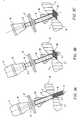
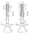
Fig. 1A illustrates a blunt obturator of the access assembly.Fig. 1B shows a side-view of the access assembly with the obturator removed.Figs. 2A-2C show side-views of one embodiment of the access assembly having a single anchor.Figs. 3A-3C depict a method of the present invention using the assembly ofFigs. 2A-2C and a non-expandable sealing anchor.Fig. 4A shows a cross-section of the assembly having coupled anchors.Fig. 4B shows a cross-section of the assembly having decoupled anchors.Figs. 5A-5B depicts a method of the present invention using the assembly ofFig. 4A .Figs. 6A-6D depicts a method of the present invention using the assembly ofFig. 4B .Fig. 7A illustrates an enlarged cross-section of the distal end of the assembly fitted with a threaded tubular member.Fig. 7B shows an enlarged cross-section of the distal end of the assembly having a cannula concentrically disposed within the tubular member.- Methods and apparatus of the present invention are directed towards providing access to a gas containing body cavity without substantial loss of gas from the body during surgical procedures. Specifically, the invention prevents substantial loss of pneumoperitoneum through a penetration in the abdominal wall by providing an access assembly that can form a peripheral seal against the penetration while allowing surgical instruments to access the abdomen during minimally invasive surgical procedures.
- To reach a desired body cavity, the access assembly is inserted through a percutaneous opening in the patient's abdomen. In preferred embodiments, the opening occurs through the umbilicus of the patient. The access assembly must typically pass through the abdominal wall which includes the outer skin, a layer of fat, a layer of fascia or alternating muscle and fascia, and the peritoneum. The layers of fat and fascia may vary in thickness, depending upon the body location and whether the patient is asthenic or obese. The peritoneum is a strong, elastic membrane lining the walls of the abdominal cavity. Just below the peritoneum, lie several vital organs, such as the liver, stomach and intestines, and other sensitive tissues. This is typically the area that the access assembly is positioned to reach.
- To perform surgical procedures in this area, the abdominal wall is lifted off of the organs by inflating the area with an insufflation gas such as carbon dioxide. This provides sufficient space for surgical instruments to maneuver. To prevent loss of this gas and loss of space in the abdomen to operate, the access assembly must provide a gas-tight seal against the abdominal wall while permitting a sufficient range of motion for the instruments and not traumatizing the portion of the abdominal wall in the seal.
- In a basic embodiment, the
abdominal access assembly 10 of the present invention (seeFig. 2 ) generally comprises a blunt obturator 11 (Fig. 1A ) and a tubular member 12 (Fig. 1B ) having apneumostasis valve 13 fitted to theproximal end 14 of thetubular member 12. Theblunt obturator 11 slides removably into alumen 15 of thetubular member 12 throughpneumostasis valve 13 andproximal end 14 of thetubular member 12. Although ablunt obturator 11 is preferred, a variety of other instruments may also be inserted into thelumen 15 so long as they facilitate atraumatic insertion of theaccess assembly 10 into a body cavity of the patient. Thepneumostasis valve 13 may be housed inside a hub attached to thetubular member 12. Thevalve 13 may be a flap valve or a gas-restricting device of some other design, so long as it allows entry of a surgical instrument while minimizing substantial loss of insufflation gas during the surgical procedure. - To form a peripheral seal between the
access assembly 10 and a percutaneous opening in the abdominal wall, theassembly 10 has afirst sleeve 16 disposed coaxially over thetubular member 12. Thesleeve 16 is connected to ahandle 17 and both slide over thetubular member 12. Thesleeve 16 comprises a proximalnonexpandable region 18 and a distal expandable region 19 (seeFig. 2 ).End 20 on theexpandable region 19 is connected todistal end 21 on thetubular member 12 so that thesleeve 16 can slide over but not detach fromtubular member 12. Thehandle 17 is used to axially translate thesleeve 16 which results in the compression ofregion 19. The distalexpandable region 19 expands radially when axially compressed to form distal expanded occlusion member oranchor 30. As will be discussed below, the expandedanchor 30 forms a peripheral seal to prevent the loss of gas from the body cavity. - To axially translate the
sleeve 16 over thetubular member 12, a variety of mechanisms can be employed such as using a pistol grip advancing system or some other translating mechanism. All must, however, effectuate axial compression of the distalexpandable region 19. A convenient way to axially compress the distalexpandable region 19 is to prevent axial movement of thetubular member 12 and the distal end ofregion 19 while axially advancing thesleeve 16 in the distal direction. An exemplary mechanism for axially translating thesleeve 16 relative to thetubular member 12 is handle 17 as shown inFigs. 1-6 . - In a specific aspect of the present invention for forming a peripheral seal, the distal
expandable region 19 ofsleeve 16 is a non-distensible imperforate cylindrical surface preferably constructed from an elastomeric sheet covering a mesh or braided material, as shown in the figures. Specific methods for forming and details regarding the elastomeric sheet and the mesh are described in commonly assignedU.S. Patent No. 5,540,658 to Evans et al. , the complete disclosure of which is incorporated herein by reference. Exemplary materials for the mesh or braided material include polymer strands such as PET, polypropylene, polyethylene, and the like. Exemplary materials for the elastomeric sheet include latex, silicone, thermoplastic elastomers (such as C-Flex, commercially available from Consolidated Polymer Technology), and the like. The mesh is formed into a cylindrical geometry and, as mentioned, is translatably disposed overtubular member 12. The distal ends of both the mesh and sheet are attached to thedistal end 21 oftubular member 12 so that when theexpandable region 19 is axially compressed, theexpandable region 19 will both axially compress and radially expand to form the distal expandedanchor 30. To ensure that theexpandable region 19 will radially expand to the desired configuration, the mesh can be pre-fatigued, heat forged or bonded in preselected locations, e.g., along a circumferential line. When the mesh is axially compressed, the mesh will radially expand about the line. - In an exemplary aspect, the mesh can also be used to form the
tubular body 12 by proximally extending the mesh from theexpandable region 19. A cover tube can be placed over the extended mesh so that the exterior surface of thetubular body 12 is substantially flush with theexpandable region 19. An exemplary material for constructing the cover tube is a cross linked heat shrink polymer. In this manner, theexpandable region 19 can be made to closely conform to the exterior of thetubular member 12. - The
tubular member 12 can be constructed from a variety of materials including stainless steel, composite filament wound polymer, or extruded polymer tubing (such asNylon 11 or Ultem, commercially available from General Electric), and the like. These materials have sufficient strength so that thetubular body 12 will not collapse when inserted into the abdomen or when the distalexpandable region 19 is compressed. Although specific dimension vary depending on the surgical procedure, thetubular member 12 has an outer diameter from about 4 mm to 20 mm and a length between about 5 cm and 15 cm. - Referring to
Figs. 2-3 ,access assembly 10 is shown fully assembled with theblunt obturator 11 inserted into thetubular member 12.Fig. 2A-2C shows anaccess assembly 10 capable of forming a single expandedanchor 30. As thesleeve 16 is axially translated towards a distal end of thetubular member 12 inFig. 2B , theexpandable region 19 compresses to cause radial expansion. InFig. 2C , theregion 19 has reached maximum radial expansion and forms thesingle anchor 30. Theanchor 30 generally assumes a conical configuration which diverges in the distal direction when axially compressed. Preferably, the maximum outer diameter of thedistal anchor 30 will be in the range from about 10 mm to 50 mm. Figs. 3A-3C depicts an alternate embodiment of the present invention and a method for the present invention. The device ofFigs. 3A-3C is essentially theassembly 10 ofFigs. 2A-2C further comprising anon-expanding sealing anchor 40 sliding coaxially oversleeve 16. Thenon-expanding anchor 40 is typically a cone structure which diverges in the proximal direction. The expandedanchor 30 andnon-expanding anchor 40 will slide to clamp around abdominal wall W to form a peripheral seal.- The method of the present invention as illustrated in
Fig. 3A showsaccess assembly 10 inserted into a percutaneous opening O made in abdominal wall W. Preferably, the opening O was made using the Hasson method, which avoids the use of a trocar and reduces risk for organ puncture. Theblunt obturator 11 helps the assembly push aside tissue without trauma. Theaccess assembly 10 is positioned at a depth so that distalexpandable region 19 will form theanchor 30 on the interior side I of abdominal wall W. Fig. 3B shows theanchor 30 forming a seal against the interior side I of the abdominal wall W. Thesleeve 16 has translated axially towards the distal end and has compressedregion 19 to formanchor 30.Non-expanding anchor 40 is advanced axially towards the distal end of thetubular member 12 to form a reduced diameter neck withanchor 30. The non-expanding anchor seals against the interior of opening O and, the exterior surface E of the abdominal wall W. Theanchors assembly 10 and also to prevent loss of pneumoperitoneum from the abdomen. After theaccess assembly 10 is secured and peripherally sealed to the puncture, theblunt obturator 11 is removed from thetubular member 12 so that surgical instruments (not shown) can be inserted into thelumen 15 oftubular member 12 to access the body cavity below (seeFig. 3C ). Thepneumostasis valve 13 prevents loss of gas by automatically closing access to thetubular member 12 when surgical instruments are being switched.- In further embodiments of the device of the present invention,
Figs. 4A and 4B show anaccess assembly obturator 11 removed) capable of forming a distal expandedanchor 30 and an intermediate expandedanchor 50. Having two expanded anchors integrated onto the access assembly reduces the need for extra parts like thenon-expanding anchor 40 and results in a more compact, integrated device. - The embodiment of
Fig. 4A shows anaccess assembly 10B (withobturator 11 removed) comprising asleeve 16 having distalexpandable region 19 and an intermediateexpandable region 51. Whensleeve 16 is advanced towards the distal end of thetubular member 12, bothexpandable regions distal anchor 30 andintermediate anchor 50, respectively. The expansion of these regions are coupled, as either both regions expand or neither expand. Again the distal end ofexpandable region 19 is connected to the distal end oftubular member 12. Preferably, the maximum expanded outer diameter of the intermediate anchor will be in the range from about 10 mm to 50 mm. - In the embodiment of
Fig. 4B , anaccess assembly 10C (shown withobturator 11 removed) hasexpandable regions assembly 10C has asecond sleeve 61 that is slidably disposed overfirst sleeve 16 in a coaxial manner and has anactivation handle 62. Thesecond sleeve 61 is preferably fitted over thenon-expanding portion 18 of thefirst sleeve 16. This decoupled configuration allows for sequential, as well as simultaneous, deployment ofanchors region 60, which is located at the distal end ofsleeve 61, is independent of any radial expansion of distalexpandable region 19. A distal end ofsecond sleeve 61 is fixedly attached to thenonexpandable region 18 ofsleeve 16. This preventssecond sleeve 61 from falling off of thesleeve 16 and provides a fixed point against whichregion 60 axially compresses. The embodiment ofFig. 4B allows for decoupled activation ofintermediate anchor 50 anddistal anchor 30. - Referring to
Figs. 5A-5B , a further method of the present invention is depicted using the assembly ofFig. 4A having the coupled anchors. After abdominal wall W has been penetrated, theassembly 10B is inserted into the opening O to a depth sufficient to have thedistal anchor 30 seal on an interior surface I of the wall. The position of theassembly 10B will also allow the intermediate expandedanchor 50 to form a seal on the exterior surface E of the abdominal wall W. Thesleeve 16 is translated axially towards thedistal end 21 of the assembly, causing bothexpandable regions intermediate anchor 50 will preferably have a conical configuration which diverges in the proximal direction so that the expanded anchors 30 and 50 when brought together define aneck 41 having opposed tapered walls. After the seal is formed, theobturator 11 is removed fromlumen 15 of the tubular member 12 (not shown). Figs. 6A-6D depict a still further method of the present invention using the access assembly ofFig. 4B having decoupledanchors assembly 10C is inserted through an opening O in the abdominal wall W. Then either the distal or intermediate expandable regions may be compressed to form an anchor. Preferably, the distal region will be expanded first. This allowsanchor 30 to be retracted against the interior surface I of the wall W to ensure a conforming seal (seeFig 6B ). The seal, however, is not so tight as to cause trauma to the abdominal wall. Both the first andsecond sleeves Fig. 6C , causing expandedanchors Fig. 6D shows theobturator 11, used to facilitate entry of theassembly 10C into the opening, removed fromlumen 15 to allow surgical instruments access though thetubular member 12 to the body cavity below.- To more suitably handle changing conditions that may be encountered during a surgical procedure, it is further desirable that the depth or length of the
access assembly 10, protruding beyond theexpandable anchor 30 and into the body cavity, be adjustable. This may be accomplished through a variety of methods, so long asexpandable anchor 30 has a secured point of reference against which theanchor 30 may compress against, once the depth or length of the assembly extending into the cavity has been adjusted. - For example,
Figure 7A depicts the distal end of anassembly 10D with a threadedtubular member 112 which can be rotated to extend further into the abdominal cavity (as indicated by the arrows) while theanchors member 112 mates with threadedend 113 onfirst sleeve 16 to provide axial resistance for theanchor 30, while still allowing for the threadedtubular member 112 to be extended or retracted through rotational motion. The threadedtubular member 112 would likely be manipulable or rotatable from the proximal end of theassembly 10D so that adjustments can be made while the assembly is clamped around the abdominal wall. As shown by unthreadedregion 114, thethreads 115 of themember 112 do not necessarily extend along the entire outer surface of themember 112. Figure 7B depicts an alternative embodiment for varying the depth of which theassembly 10 extends into the abdominal cavity. A cannula 120 is added to theassembly 10 and is slidably disposed concentrically within thetubular member 12. The cannula 120 translates axially (as indicated by arrows) to extend or retract from the body cavity.- Preferably, the cannula 120 would extend along the entire length of
tubular member 12 and be manipulable from a proximal end of theassembly 10. This particular embodiment of the present invention has the advantage of not requiring significant modification of theassembly 10. A still further embodiment of the invention may use a collet mechanism or ratcheting-type mechanism (not shown) on a distal end ofanchor 30 to lock and unlock abouttubular member 12 as the length which theassembly 10 protrudes into the body cavity is adjusted. This allows for axial adjustability while providing the necessary secured point of reference foranchor 30 to compress against, once length adjustments have been completed. - Although the foregoing invention has been described in detail for purposes of clarity of understanding, it will be obvious that certain modifications may be practiced within the scope of the appended claims.
- The invention will now be described in further detail in the following numbered paragraphs:
- 1. An abdominal access assembly comprising: a tubular member having a proximal end, a distal end, and a lumen therethrough; a first sleeve disposed coaxially over the tubular member, said sleeve having: (a) a distal radially expandable region, (b) a proximal nonexpandable region, wherein the sleeve is shiftable over the tubular member between an axially elongated configuration where the distal region is unexpanded and an axially shortened configuration where the distal region is radially expanded; a pneumostasis valve attached to the proximal end of the tubular member; and an obturator removably receivable in the lumen of the tubular member.
- 2. An assembly of paragraph 1 further comprising a nonexpandable sealing anchor slidably mounted over the proximal non-expandable region of the sleeve, wherein the nonexpandable sealing anchor can be advanced toward the radially expanded, expandable region to clamp a patient's abdominal tissue.
- 3. An assembly of paragraph 2 wherein the sealing anchor has a conical configuration which diverges in the proximal direction so that the expanded distal, expandable region and the sealing anchor when brought together define a neck having opposed tapered walls.
- 4. An assembly of paragraph 1 wherein: said sleeve has an intermediate radially expandable region; said sleeve is shiftable over the tubular member between an axially elongated configuration where both the distal and the intermediate regions are unexpanded and an axially shortened configuration where both the distal and the intermediate regions are radially expanded.
- 5. An assembly of paragraph 1 further comprising: a second sleeve disposed coaxially over the proximal non-expandable region of said first sleeve, said second sleeve having a distal, a proximal end, and an intermediate radially expandable region; said intermediate region attached to the distal end of the second sleeve, wherein the second sleeve is shiftable over said first sleeve between an axially elongated configuration where the intermediate region is unexpanded and an axially shortened configuration where the intermediate region is radially expanded.
- 6. An assembly of paragraph 1 wherein the distal expandable region comprises a non-distensible imperforate cylinder.
- 7. An assembly of paragraph 1 wherein the distal expandable region comprises a radially expandable mesh covered with an elastomer sheath.
- 8. An assembly of paragraph 1 wherein the tubular member has a length in the range from 5 to 15 cm and an outside diameter in the range from 4 to 20 mm.
- 9. An assembly of paragraph 1 sized to be received into the umbilicus of the patient.
- 10. An assembly of paragraph 1 wherein a length of said tubular member extends beyond the distal end of the first sleeve, said length being adjustable in the axial direction.
- 11. An assembly of paragraph 1 further comprising a cannula contained concentrically within said tubular member, said cannula being slidably disposed within said member.
- 12. A method for providing access to a patient's abdomen, said method comprising:
- introducing a tubular body through a penetration in the patient's abdomen; axially compressing a radially expandable member mounted on the tubular body to radially expand the member to provide a seal against the internal surface of an abdominal wall; and insufflating the abdomen with a gas, wherein the seal inhibits loss of the gas through the penetration.
- 13. A method of
paragraph 12 further comprising axially advancing a proximal anchor on said tubular body to clamp against the abdominal wall. - 14. A method of
paragraph 12 wherein the axially compressing step comprises compressing an intermediate radially expandable member and a distal radially expandable member to radially expand both said members to clamp an abdominal wall therebetween, said distal member providing a seal against the internal surface of an abdominal wall. - 15. A method of
paragraph 14 wherein the distal and intermediate radially expandable members are axially compressed simultaneously. - 16. A method of
paragraph 14 wherein the distal and intermediate radially expandable members are axially compressed sequentially. - 17. A method of
paragraph 12 wherein the penetration occurs through the patient's umbilicus. - 18. A method of
paragraph 12 wherein: said tubular body has a lumen therethrough, said lumen contains a removably receivable blunt obturator.
Claims (12)
- An abdominal access assembly (10) comprising:a tubular member (12) having a proximal end, a distal end, and a lumen therethrough;a first sleeve (16) disposed coaxially over the tubular member, said sleeve having: (a) a distal radially expandable region (30), (b) a proximal non-expandable region, wherein the sleeve is shiftable over the tubular member between an axially elongated configuration where the distal region is unexpanded and an axially shortened configuration where the distal region is radially expanded;a pneumostasis valve attached to the proximal end of the tubular member;andan obturator removably receivable in the lumen of the tubular member;wherein the distal radially expandable region (30) has a secured point of reference on the sleeve (16) to compress against such that said length of tubular member is adjustable in the axial direction beyond the distal end of the first sleeve (16).
- An abdominal access assembly (10) according to claim 1 wherein the secured point of reference is provided by a threaded tubular member (112) mated with a threaded end (113) on sleeve (16).
- An abdominal access assembly (10) according to claim 1 wherein the secured point of reference is provided by a collet mechanism or ratcheting-type mechanism on a distal end of distally expandable region (30).
- An assembly of claim 1 further comprising a non-expandable sealing anchor slidably mounted over the proximal non-expandable region of the sleeve, wherein the non-expandable sealing anchor can be advanced toward the radially expanded, expandable region to clamp a patient's abdominal tissue.
- An assembly of claim 4 wherein the sealing anchor has a conical configuration which diverges in the proximal direction so that the expanded distal, expandable region and the sealing anchor when brought together define a neck having opposed tapered walls.
- An assembly of claim 1 wherein: said sleeve has an intermediate radially expandable region; said sleeve is shiftable over the tubular member between an axially elongated configuration where both the distal and the intermediate regions are unexpanded and an axially shortened configuration where both the distal and the intermediate regions are radially expanded.
- An assembly of claim 1 further comprising: a second sleeve disposed coaxially over the proximal non-expandable region of said first sleeve, said second sleeve having a distal, a proximal end, and an intermediate radially expandable region; said intermediate region attached to the distal end of the second sleeve, wherein the second sleeve is shiftable over said first sleeve between an axially elongated configuration where the intermediate region is unexpanded and an axially shortened configuration where the intermediate region is radially expanded.
- An assembly of claim 1 wherein the distal expandable region comprises a non-distensible imperforate cylinder.
- An assembly of claim 1 wherein the distal expandable region comprises a radially expandable mesh covered with an elastomer sheath.
- An assembly of claim 1 wherein the tubular member has a length in the range from 5 to 15 cm and an outside diameter in the range from 4 to 20 mm.
- An assembly of claim 1 sized to be received into the umbilicus of the patient.
- An assembly of claim 1 further comprising a cannula contained concentrically within said tubular member, said cannula being slidably disposed within said member.
Applications Claiming Priority (3)
| Application Number | Priority Date | Filing Date | Title |
|---|---|---|---|
| US08/850,795US5836913A (en) | 1997-05-02 | 1997-05-02 | Device and method for accessing a body cavity |
| EP09010756AEP2111807B1 (en) | 1997-05-02 | 1998-05-01 | Device for accessing a body cavity |
| EP98920134AEP1015069B1 (en) | 1997-05-02 | 1998-05-01 | Device for accessing a body cavity |
Related Parent Applications (2)
| Application Number | Title | Priority Date | Filing Date |
|---|---|---|---|
| EP98920134.8Division | 1998-11-12 | ||
| EP09010756.6Division | 2009-08-21 |
Publications (1)
| Publication Number | Publication Date |
|---|---|
| EP2258286A2true EP2258286A2 (en) | 2010-12-08 |
Family
ID=25309130
Family Applications (3)
| Application Number | Title | Priority Date | Filing Date |
|---|---|---|---|
| EP98920134AExpired - LifetimeEP1015069B1 (en) | 1997-05-02 | 1998-05-01 | Device for accessing a body cavity |
| EP09010756AExpired - LifetimeEP2111807B1 (en) | 1997-05-02 | 1998-05-01 | Device for accessing a body cavity |
| EP10011045AWithdrawnEP2258286A2 (en) | 1997-05-02 | 1998-05-01 | Device for accessing a body cavity |
Family Applications Before (2)
| Application Number | Title | Priority Date | Filing Date |
|---|---|---|---|
| EP98920134AExpired - LifetimeEP1015069B1 (en) | 1997-05-02 | 1998-05-01 | Device for accessing a body cavity |
| EP09010756AExpired - LifetimeEP2111807B1 (en) | 1997-05-02 | 1998-05-01 | Device for accessing a body cavity |
Country Status (4)
| Country | Link |
|---|---|
| US (1) | US5836913A (en) |
| EP (3) | EP1015069B1 (en) |
| DE (1) | DE69841405D1 (en) |
| WO (1) | WO1998050104A1 (en) |
Cited By (1)
| Publication number | Priority date | Publication date | Assignee | Title |
|---|---|---|---|---|
| EP3991671A1 (en)* | 2020-10-29 | 2022-05-04 | Covidien LP | Surgical access device with fixation mechanism and illumination mechanism |
Families Citing this family (226)
| Publication number | Priority date | Publication date | Assignee | Title |
|---|---|---|---|---|
| SE509513C2 (en)* | 1996-09-16 | 1999-02-08 | Endolink Ab | Tools for use in surgical procedures on the uterus and cervix |
| GB9717821D0 (en)* | 1997-08-21 | 1997-10-29 | Spinoza Marc H | Fasteners |
| US6033420A (en)* | 1998-09-02 | 2000-03-07 | Embol-X, Inc. | Trocar introducer system and methods of use |
| US7044134B2 (en) | 1999-11-08 | 2006-05-16 | Ev3 Sunnyvale, Inc | Method of implanting a device in the left atrial appendage |
| US7128073B1 (en) | 1998-11-06 | 2006-10-31 | Ev3 Endovascular, Inc. | Method and device for left atrial appendage occlusion |
| JP4105395B2 (en)* | 1999-03-17 | 2008-06-25 | タイコ ヘルスケア グループ リミテッド パートナーシップ | Self-holding surgical access instrument |
| EP1194074A4 (en)* | 1999-05-19 | 2002-09-11 | Innerdyne Medical Inc | SYSTEM AND METHOD TO ENABLE VASCULAR ACCESS |
| US6692462B2 (en)* | 1999-05-19 | 2004-02-17 | Mackenzie Andrew J. | System and method for establishing vascular access |
| US6231561B1 (en) | 1999-09-20 | 2001-05-15 | Appriva Medical, Inc. | Method and apparatus for closing a body lumen |
| US6652555B1 (en) | 1999-10-27 | 2003-11-25 | Atritech, Inc. | Barrier device for covering the ostium of left atrial appendage |
| US6689150B1 (en) | 1999-10-27 | 2004-02-10 | Atritech, Inc. | Filter apparatus for ostium of left atrial appendage |
| US6551303B1 (en) | 1999-10-27 | 2003-04-22 | Atritech, Inc. | Barrier device for ostium of left atrial appendage |
| US6648906B2 (en) | 2000-04-06 | 2003-11-18 | Innercool Therapies, Inc. | Method and apparatus for regulating patient temperature by irrigating the bladder with a fluid |
| CA2404092A1 (en)* | 2000-04-11 | 2001-10-18 | James Teague | Reinforced retention structures |
| US6589208B2 (en)* | 2000-06-20 | 2003-07-08 | Applied Medical Resources Corporation | Self-deploying catheter assembly |
| US6811546B1 (en) | 2000-08-25 | 2004-11-02 | Origin Medsystems, Inc. | Endoscopic surgical access port and method |
| EP1318766A2 (en) | 2000-09-21 | 2003-06-18 | Atritech, Inc. | Apparatus for implanting devices in atrial appendages |
| US6592573B2 (en) | 2000-10-11 | 2003-07-15 | Popcab, Llc | Through-port heart stabilization system |
| US6464691B1 (en) | 2000-10-11 | 2002-10-15 | Popcab, Llc | Port device for port off-pump beating heart coronary artery bypass surgery system |
| US6582420B2 (en) | 2000-10-11 | 2003-06-24 | Popcab, Llc | Intercostal lockable directable port device |
| US6503245B2 (en) | 2000-10-11 | 2003-01-07 | Medcanica, Inc. | Method of performing port off-pump beating heart coronary artery bypass surgery |
| US6464690B1 (en) | 2000-10-11 | 2002-10-15 | Popcab, Llc | Port off-pump beating heart coronary artery bypass heart stabilization system |
| US6355028B2 (en) | 2000-10-11 | 2002-03-12 | Popcab,Llc | Stable port device for port off-pump beating heart coronary artery bypass surgery system |
| US7041055B2 (en)* | 2002-10-07 | 2006-05-09 | Mark LoGuidice | Instruments and methods for use in laparoscopic surgery |
| US20060025781A1 (en)* | 2001-01-17 | 2006-02-02 | Young Wayne P | Laparoscopic instruments and methods utilizing suction |
| US6958069B2 (en)* | 2001-01-17 | 2005-10-25 | Mark LoGuidice | Instruments and methods for use in laparoscopic surgery |
| AU2002321685A1 (en)* | 2001-04-02 | 2002-11-11 | The Hook Research Foundation | Conformable balloonless catheter |
| CA2449468A1 (en)* | 2001-06-04 | 2002-12-12 | Albert Einstein Healthcare Network | Cardiac stimulating apparatus having a blood clot filter and atrial pacer |
| US7011671B2 (en) | 2001-07-18 | 2006-03-14 | Atritech, Inc. | Cardiac implant device tether system and method |
| EP1418850B1 (en) | 2001-08-01 | 2010-10-06 | Tyco Healthcare Group LP | Apparatus for providing percutaneous access and medicament to a target surgical site |
| US20030181942A1 (en) | 2002-01-25 | 2003-09-25 | Sutton Gregg S. | Atrial appendage blood filtration systems |
| AU2003213189A1 (en)* | 2002-02-21 | 2003-09-09 | Andre M. Persidsky | Apparatus and method for making a percutaneous access for port of variable size |
| US7377897B1 (en) | 2002-05-02 | 2008-05-27 | Kunkel Sanford S | Portal device |
| US7300448B2 (en) | 2002-10-04 | 2007-11-27 | Tyco Healthcare Group Lp | Balloon dissector with cannula |
| JP4546247B2 (en) | 2002-10-04 | 2010-09-15 | タイコ ヘルスケア グループ エルピー | Balloon dissector with cannula |
| US7896897B2 (en) | 2002-11-22 | 2011-03-01 | Tyco Healthcare Group Lp | Sheath introduction apparatus and method |
| US6913611B2 (en)* | 2002-12-03 | 2005-07-05 | Gerard Cappiello | Rectosigmoid manipulator apparatus |
| US7347866B2 (en)* | 2003-03-10 | 2008-03-25 | Boston Scientific Scimed, Inc. | Medical stent and related methods |
| US20050143690A1 (en)* | 2003-05-01 | 2005-06-30 | High Kenneth A. | Cystotomy catheter capture device and methods of using same |
| WO2004100799A2 (en) | 2003-05-08 | 2004-11-25 | Tyco Healthcare Group Lp | Balloon dissector with balloon anchor cannula |
| US7479150B2 (en) | 2003-09-19 | 2009-01-20 | Tyco Healthcare Group Lp | Trocar insertion apparatus |
| JP4642769B2 (en)* | 2003-10-17 | 2011-03-02 | タイコ ヘルスケア グループ リミテッド パートナーシップ | Expandable surgical access device |
| CA2762928C (en)* | 2003-10-17 | 2014-09-16 | Tyco Healthcare Group Lp | Surgical access device and manufacture thereof |
| US20050197627A1 (en) | 2004-03-05 | 2005-09-08 | Percutaneous Systems, Inc. | Method and system for deploying protective sleeve in intraluminal catherization and dilation |
| US7425202B2 (en)* | 2004-03-05 | 2008-09-16 | Percutaneous Systems, Inc. | Non-seeding biopsy device and method |
| US7572274B2 (en)* | 2004-05-27 | 2009-08-11 | Cardiva Medical, Inc. | Self-tensioning vascular occlusion device and method for its use |
| US20080154303A1 (en) | 2006-12-21 | 2008-06-26 | Cardiva Medical, Inc. | Hemostasis-enhancing device and method for its use |
| US7993366B2 (en)* | 2004-05-27 | 2011-08-09 | Cardiva Medical, Inc. | Self-tensioning vascular occlusion device and method for its use |
| US7500972B2 (en)* | 2004-05-07 | 2009-03-10 | Ethicon Endo-Surgery, Inc. | Device for alternately holding, or effecting relative longitudinal movement, of members of a medical instrument |
| US8257394B2 (en) | 2004-05-07 | 2012-09-04 | Usgi Medical, Inc. | Apparatus and methods for positioning and securing anchors |
| EP1765451B1 (en)* | 2004-06-14 | 2021-11-17 | Edwards Lifesciences Corporation | Devices for arterio-venous fistula creation |
| US7972292B2 (en)* | 2005-07-06 | 2011-07-05 | Percutaneous Systems, Inc. | Methods and apparatus for deploying ureteral stents |
| US7462183B2 (en)* | 2004-07-07 | 2008-12-09 | Percutaneous Systems, Inc. | Methods for deploying conformed structures in body lumens |
| US7883516B2 (en)* | 2004-07-07 | 2011-02-08 | Percutaneous Systems, Inc. | Methods for removing kidney stones from the ureter |
| US20060079845A1 (en)* | 2004-10-08 | 2006-04-13 | Eben Howard And Pamela A. Howard | Movable inflatable anchor for medical devices |
| WO2006044797A2 (en)* | 2004-10-18 | 2006-04-27 | The Henry M Jackson Foundation For The Advancement Of Military Medicine, Inc. | Device for displacement of anterior abdominal wall |
| WO2006074044A2 (en)* | 2004-12-30 | 2006-07-13 | Neomend, Inc. | Method and apparatus for percutaneous wound sealing |
| US20060173525A1 (en)* | 2005-02-02 | 2006-08-03 | Percutaneous Systems, Inc. | Methods and systems for deploying luminal prostheses |
| US7708748B2 (en)* | 2005-03-30 | 2010-05-04 | Ethicon Endo-Surgery, Inc. | Anastomosis device |
| DE102005021470A1 (en)* | 2005-05-10 | 2006-11-16 | Tracoe Medical Gmbh | Introducer for percutaneous tracheostomy |
| US7691089B2 (en)* | 2005-06-21 | 2010-04-06 | Tyco Healthcare Group Lp | Adjustable trocar washer |
| GB2429154B (en)* | 2005-07-13 | 2011-06-01 | Sull Ltd | Apparatus for securing a line to a patient |
| US8029522B2 (en)* | 2005-08-05 | 2011-10-04 | Ethicon Endo-Surgery, Inc. | Method and apparatus for sealing a gastric opening |
| US9554788B1 (en)* | 2005-08-12 | 2017-01-31 | Michael R. Redler | Methods and apparatus for performing arthroscopic surgery |
| US20070078386A1 (en)* | 2005-08-30 | 2007-04-05 | Cytyc Corporation | Movable anchoring catheter |
| US7972359B2 (en) | 2005-09-16 | 2011-07-05 | Atritech, Inc. | Intracardiac cage and method of delivering same |
| US20070073107A1 (en)* | 2005-09-23 | 2007-03-29 | Percutaneous Systems, Inc. | Methods and systems for sheathing tubular medical instruments |
| JP2009509669A (en)* | 2005-09-27 | 2009-03-12 | シネコー・エルエルシー | Transgastric surgery device and procedure |
| US7811251B2 (en) | 2005-10-13 | 2010-10-12 | Tyco Healthcare Group Lp | Trocar anchor |
| US20070106233A1 (en)* | 2005-10-20 | 2007-05-10 | Percutaneous Systems, Inc. | Systems and methods for dilating and accessing body lumens |
| US8157833B2 (en) | 2005-11-09 | 2012-04-17 | Applied Medical Resources Corporation | Trocars with advanced fixation |
| US9179897B2 (en) | 2005-12-13 | 2015-11-10 | Cardiva Medical, Inc. | Vascular closure devices and methods providing hemostatic enhancement |
| US7691127B2 (en)* | 2005-12-13 | 2010-04-06 | Cardiva Medical, Inc. | Drug eluting vascular closure devices and methods |
| US8911472B2 (en) | 2005-12-13 | 2014-12-16 | Cardiva Medical, Inc. | Apparatus and methods for delivering hemostatic materials for blood vessel closure |
| US7776043B2 (en)* | 2006-01-26 | 2010-08-17 | Warsaw Orthopedic, Inc. | Osteochondral implant fixation procedure and bone dilator used in same |
| WO2007093957A2 (en)* | 2006-02-17 | 2007-08-23 | Roesch Theodor Gerhard | A cannula with a deployable external thread |
| US8147453B2 (en)* | 2006-03-13 | 2012-04-03 | Applied Medical Resources Corporation | Balloon trocar |
| US8287503B2 (en) | 2006-03-13 | 2012-10-16 | Applied Medical Resources Corporation | Balloon trocar |
| US8066673B2 (en)* | 2006-03-21 | 2011-11-29 | Applied Medical Resources Corporation | Cannula stabilization seal |
| US8328836B2 (en)* | 2006-05-01 | 2012-12-11 | Ethicon Endo-Surgery, Inc. | Flexible endoscopic safety needle |
| US8870916B2 (en) | 2006-07-07 | 2014-10-28 | USGI Medical, Inc | Low profile tissue anchors, tissue anchor systems, and methods for their delivery and use |
| US20080033396A1 (en)* | 2006-08-01 | 2008-02-07 | Percutaneous Systems, Inc. | Vascular sheaths and methods for their deployment |
| CA2594239A1 (en)* | 2006-08-02 | 2008-02-02 | Tyco Healthcare Group Lp | Stabilization assist device for trocar |
| US8795235B2 (en)* | 2006-10-06 | 2014-08-05 | Surgiquest, Inc. | Devices for and methods of performing minimally-invasive surgical procedures through a single incision |
| US8298213B2 (en)* | 2006-12-21 | 2012-10-30 | Steven Jiwan Singh | Medical instrument |
| WO2008115505A1 (en)* | 2007-03-21 | 2008-09-25 | The Trustees Of The University Of Pennsylvania | Natural orifice transluminal endoscopic surgery overtube and method of introducing multiple endoscopes |
| US8142356B2 (en) | 2007-03-30 | 2012-03-27 | Ethicon Endo-Surgery, Inc. | Method of manipulating tissue |
| US8100930B2 (en)* | 2007-03-30 | 2012-01-24 | Ethicon Endo-Surgery, Inc. | Tissue moving surgical device |
| WO2009009221A2 (en)* | 2007-05-18 | 2009-01-15 | Boston Scientific Scimed, Inc. | Methods and devices for traversing an anatomic wall |
| WO2008154578A1 (en)* | 2007-06-11 | 2008-12-18 | Board Of Regents, The University Of Texas System | Characterization of a near-infrared laparoscopic hyperspectral imaging system |
| US7879066B2 (en)* | 2007-07-13 | 2011-02-01 | Percutaneous Sustems, Inc. | Apparatus for occluding body lumens |
| US8475489B2 (en)* | 2007-07-13 | 2013-07-02 | Percutaneous Systems, Inc. | Apparatus for occluding body lumens |
| US8157727B2 (en)* | 2007-07-16 | 2012-04-17 | Ethicon Endo-Surgery, Inc. | Surgical methods and devices with movement assistance |
| US8118826B2 (en)* | 2007-09-27 | 2012-02-21 | Swan Valley Medical, Incorporated | Method of performing a suprapubic transurethral cystostomy and associated procedures and apparatus therefor |
| US8382785B2 (en)* | 2007-09-27 | 2013-02-26 | Swan Valley Medical Incorporated | Apparatus and method for performing cystotomy procedures |
| US8795326B2 (en) | 2007-10-05 | 2014-08-05 | Covidien Lp | Expanding seal anchor for single incision surgery |
| US20090093752A1 (en) | 2007-10-05 | 2009-04-09 | Tyco Healthcare Group Lp | Seal anchor for use in surgical procedures |
| WO2009048949A1 (en)* | 2007-10-09 | 2009-04-16 | Wilson-Cook Medical, Inc. | Anastomosis plug for bariatric surgery |
| EP2214584A2 (en)* | 2007-11-15 | 2010-08-11 | Medizinische Universität Wien | Method and device for carrying out a percrestale sinus lift |
| US20090204081A1 (en)* | 2008-02-13 | 2009-08-13 | Depuy Mitek, Inc. | Compression expanded cannula |
| EP2259733B1 (en)* | 2008-03-06 | 2014-07-23 | Cook Medical Technologies LLC | Medical systems for accessing an internal bodily opening |
| US8540744B2 (en)* | 2008-04-01 | 2013-09-24 | Ethicon Endo-Surgery, Inc. | Tissue penetrating surgical device |
| US8142467B2 (en)* | 2008-04-21 | 2012-03-27 | Applied Medical Resources Corporation | Tamponade trocar device and method |
| US8795161B2 (en)* | 2008-06-25 | 2014-08-05 | Covidien Lp | Button port |
| USD738500S1 (en) | 2008-10-02 | 2015-09-08 | Covidien Lp | Seal anchor for use in surgical procedures |
| US10117674B2 (en)* | 2008-10-23 | 2018-11-06 | Stryker Corporation | Cannula anchor |
| GB2464932B (en) | 2008-10-28 | 2013-07-03 | Braidlock Ltd | Methods and apparatus for securing a line |
| WO2010065556A1 (en) | 2008-12-01 | 2010-06-10 | Percutaneous Systems, Inc. | Methods and systems for capturing and removing urinary stones from body cavities |
| US8267857B2 (en) | 2009-01-30 | 2012-09-18 | Cook Medical Technologies Llc | Expandable port for accessing a bodily opening |
| US7988669B2 (en) | 2009-02-17 | 2011-08-02 | Tyco Healthcare Group Lp | Port fixation with filament actuating member |
| US8221317B2 (en)* | 2009-02-24 | 2012-07-17 | Hospital For Special Surgery | Expanding cannula and retractor device and methods of use |
| US8409085B2 (en) | 2009-02-25 | 2013-04-02 | Joint Product Solutions, Llc | Surgical retention port and method of use |
| EP2401007A1 (en) | 2009-02-25 | 2012-01-04 | Joint Product Solutions, LLC | Surgical retention port and method of use |
| US9173677B2 (en)* | 2009-07-08 | 2015-11-03 | Covidien Lp | Apparatus and method for transvaginal surgery |
| US20110034886A1 (en)* | 2009-08-06 | 2011-02-10 | Angiodynamics, Inc. | Implantable medical device tool and method of use |
| US8353873B2 (en)* | 2009-12-11 | 2013-01-15 | Ethicon Endo-Surgery, Inc. | Methods and devices for providing access through tissue to a surgical site |
| US8517932B2 (en)* | 2009-12-11 | 2013-08-27 | Ethicon Endo-Surgery, Inc. | Methods and devices for providing access through tissue to a surgical site |
| US8500633B2 (en)* | 2009-12-11 | 2013-08-06 | Ethicon Endo-Surgery, Inc. | Methods and devices for providing surgical access through tissue to a surgical site |
| US8444557B2 (en)* | 2009-12-11 | 2013-05-21 | Ethicon Endo-Surgery, Inc. | Methods and devices for providing access through tissue to a surgical site |
| US8460186B2 (en)* | 2009-12-11 | 2013-06-11 | Ethicon Endo-Surgery, Inc. | Methods and devices for providing access through tissue to a surgical site |
| EP2512569B1 (en)* | 2009-12-15 | 2014-01-22 | Danmarks Tekniske Universitet | Perforator and assembly for perforating and providing an opening |
| US20110196205A1 (en)* | 2010-02-05 | 2011-08-11 | Tyco Healthcare Group Lp | Surgical portal locking system |
| US8753267B2 (en) | 2011-01-24 | 2014-06-17 | Covidien Lp | Access assembly insertion device |
| US8888692B1 (en) | 2011-08-26 | 2014-11-18 | Applied Medical Resources Corporation | Trocar cannula assembly and method of manufacture |
| JP2015500677A (en) | 2011-11-08 | 2015-01-08 | ボストン サイエンティフィック サイムド,インコーポレイテッドBoston Scientific Scimed,Inc. | Handle assembly for left atrial appendage closure device |
| US10342548B2 (en) | 2012-01-13 | 2019-07-09 | W. L. Gore & Associates, Inc. | Occlusion devices and methods of their manufacture and use |
| WO2014079807A2 (en) | 2012-11-20 | 2014-05-30 | Trokasure Gbr | Trocar device and use thereof |
| JP6017345B2 (en)* | 2013-02-27 | 2016-10-26 | オリンパス株式会社 | Fixtures and medical devices |
| US9271752B2 (en) | 2013-03-13 | 2016-03-01 | Swan Valley Medical Incorporated | Method and apparatus for placing a cannula in a bladder |
| KR102301914B1 (en) | 2013-03-15 | 2021-09-15 | 어플라이드 메디컬 리소시스 코포레이션 | Trocar cannula assembly with low profile insertion configuration and method of manufacture |
| US10166376B2 (en) | 2013-06-11 | 2019-01-01 | Covidien Lp | Restricted expansion dissector |
| US10070853B2 (en) | 2013-08-14 | 2018-09-11 | Covidien Lp | Expandable balloon desufflation assembly |
| US9730701B2 (en) | 2014-01-16 | 2017-08-15 | Boston Scientific Scimed, Inc. | Retrieval wire centering device |
| US10064649B2 (en) | 2014-07-07 | 2018-09-04 | Covidien Lp | Pleated seal for surgical hand or instrument access |
| KR20240172766A (en)* | 2014-08-15 | 2024-12-10 | 어플라이드 메디컬 리소시스 코포레이션 | Natural orifice surgery system |
| US9707011B2 (en) | 2014-11-12 | 2017-07-18 | Covidien Lp | Attachments for use with a surgical access device |
| US9808282B2 (en)* | 2015-06-04 | 2017-11-07 | Medos International Sarl | Surgical cannula system and method of use |
| CN108882941B (en) | 2015-11-13 | 2021-08-24 | 心脏起搏器公司 | Bioabsorbable left atrial appendage closure with endothelialization-promoting surface |
| US10327809B2 (en) | 2016-02-29 | 2019-06-25 | Covidien Lp | Clip collar advanced fixation |
| WO2018039250A1 (en)* | 2016-08-24 | 2018-03-01 | Inpress Technologies, Inc. | Uterine hemorrhage controlling system and method |
| EP3614933A1 (en) | 2017-04-27 | 2020-03-04 | Boston Scientific Scimed, Inc. | Occlusive medical device with fabric retention barb |
| US11160682B2 (en) | 2017-06-19 | 2021-11-02 | Covidien Lp | Method and apparatus for accessing matter disposed within an internal body vessel |
| US10828065B2 (en) | 2017-08-28 | 2020-11-10 | Covidien Lp | Surgical access system |
| US10675056B2 (en) | 2017-09-07 | 2020-06-09 | Covidien Lp | Access apparatus with integrated fluid connector and control valve |
| US11179145B2 (en) | 2017-11-16 | 2021-11-23 | M-V Arterica AB | Collapsible tube for hemostasis |
| US20190142403A1 (en) | 2017-11-16 | 2019-05-16 | M-V Arterica AB | Tissue closure device |
| EP3727164B1 (en) | 2017-12-18 | 2024-03-13 | Boston Scientific Scimed, Inc. | Occlusive device with expandable member |
| US11413048B2 (en) | 2018-01-19 | 2022-08-16 | Boston Scientific Scimed, Inc. | Occlusive medical device with delivery system |
| US11357540B2 (en) | 2018-02-16 | 2022-06-14 | Covidien Lp | Port fixation device |
| US11051849B2 (en)* | 2018-04-06 | 2021-07-06 | Covidien Lp | Cannula assembly with collapsible fixation device |
| EP4512318A3 (en) | 2018-05-02 | 2025-04-09 | Boston Scientific Scimed, Inc. | Occlusive sealing sensor system |
| US11241239B2 (en) | 2018-05-15 | 2022-02-08 | Boston Scientific Scimed, Inc. | Occlusive medical device with charged polymer coating |
| US11123079B2 (en) | 2018-06-08 | 2021-09-21 | Boston Scientific Scimed, Inc. | Occlusive device with actuatable fixation members |
| EP3801300A1 (en) | 2018-06-08 | 2021-04-14 | Boston Scientific Scimed, Inc. | Medical device with occlusive member |
| US11382635B2 (en) | 2018-07-06 | 2022-07-12 | Boston Scientific Scimed, Inc. | Occlusive medical device |
| CN112714632B (en) | 2018-08-21 | 2024-08-30 | 波士顿科学医学有限公司 | Barbed protruding member for cardiovascular device |
| US11389193B2 (en) | 2018-10-02 | 2022-07-19 | Covidien Lp | Surgical access device with fascial closure system |
| US11457949B2 (en) | 2018-10-12 | 2022-10-04 | Covidien Lp | Surgical access device and seal guard for use therewith |
| EP3870076A4 (en)* | 2018-10-24 | 2022-08-10 | Arterica Inc. | SELF-EXPANDING HEMOSTATIC DEVICES AND METHODS FOR FASCIAL AND VASCULAR PASSAGES |
| US11166748B2 (en) | 2019-02-11 | 2021-11-09 | Covidien Lp | Seal assemblies for surgical access assemblies |
| US10792071B2 (en) | 2019-02-11 | 2020-10-06 | Covidien Lp | Seals for surgical access assemblies |
| US11369400B2 (en) | 2019-03-20 | 2022-06-28 | Covidien Lp | Balloon dissector |
| US11000313B2 (en) | 2019-04-25 | 2021-05-11 | Covidien Lp | Seals for surgical access devices |
| US11413068B2 (en) | 2019-05-09 | 2022-08-16 | Covidien Lp | Seal assemblies for surgical access assemblies |
| US11259841B2 (en) | 2019-06-21 | 2022-03-01 | Covidien Lp | Seal assemblies for surgical access assemblies |
| US11259840B2 (en) | 2019-06-21 | 2022-03-01 | Covidien Lp | Valve assemblies for surgical access assemblies |
| US11357542B2 (en) | 2019-06-21 | 2022-06-14 | Covidien Lp | Valve assembly and retainer for surgical access assembly |
| WO2020259492A1 (en)* | 2019-06-25 | 2020-12-30 | 杭州诺生医疗科技有限公司 | Atrial septostomy device |
| US11413065B2 (en) | 2019-06-28 | 2022-08-16 | Covidien Lp | Seal assemblies for surgical access assemblies |
| CN114126540A (en) | 2019-07-17 | 2022-03-01 | 波士顿科学医学有限公司 | Continuously covered left atrial appendage implant |
| US11399865B2 (en) | 2019-08-02 | 2022-08-02 | Covidien Lp | Seal assemblies for surgical access assemblies |
| EP4017384A1 (en) | 2019-08-22 | 2022-06-29 | Edwards Lifesciences Corporation | Puncture needles |
| EP4563099A3 (en) | 2019-08-30 | 2025-08-06 | Boston Scientific Scimed, Inc. | Left atrial appendage implant with sealing disk |
| US11523842B2 (en) | 2019-09-09 | 2022-12-13 | Covidien Lp | Reusable surgical port with disposable seal assembly |
| US11432843B2 (en) | 2019-09-09 | 2022-09-06 | Covidien Lp | Centering mechanisms for a surgical access assembly |
| US11812991B2 (en) | 2019-10-18 | 2023-11-14 | Covidien Lp | Seal assemblies for surgical access assemblies |
| CR20220218A (en) | 2019-11-14 | 2022-08-22 | Edwards Lifesciences Corp | Transcatheter medical implant delivery |
| EP4061244A4 (en) | 2019-11-19 | 2024-06-19 | Arterica Inc. | VASCULAR CLOSURE DEVICES AND METHODS |
| US11464540B2 (en) | 2020-01-17 | 2022-10-11 | Covidien Lp | Surgical access device with fixation mechanism |
| US12324606B2 (en) | 2020-01-28 | 2025-06-10 | Covidien Lp | Seal assemblies for surgical access assemblies |
| US11484337B2 (en) | 2020-02-06 | 2022-11-01 | Covidien Lp | Surgical access device including anchor with rachet mechanism |
| US11672563B2 (en) | 2020-02-07 | 2023-06-13 | Covidien Lp | Surgical access device with rotatably actuated fixation mechanism |
| US11547441B2 (en) | 2020-02-20 | 2023-01-10 | Covidien Lp | Retention anchor for surgical access devices |
| US12268414B2 (en) | 2020-02-26 | 2025-04-08 | Covidien Lp | Retention anchor for surgical access devices |
| US11576701B2 (en) | 2020-03-05 | 2023-02-14 | Covidien Lp | Surgical access assembly having a pump |
| US11642153B2 (en) | 2020-03-19 | 2023-05-09 | Covidien Lp | Instrument seal for surgical access assembly |
| US11541218B2 (en) | 2020-03-20 | 2023-01-03 | Covidien Lp | Seal assembly for a surgical access assembly and method of manufacturing the same |
| WO2021195085A1 (en) | 2020-03-24 | 2021-09-30 | Boston Scientific Scimed, Inc. | Medical system for treating a left atrial appendage |
| US11446058B2 (en) | 2020-03-27 | 2022-09-20 | Covidien Lp | Fixture device for folding a seal member |
| US11786233B2 (en) | 2020-03-27 | 2023-10-17 | Covidien Lp | Retention anchor with suture tie down for surgical access devices |
| US11607247B2 (en) | 2020-03-31 | 2023-03-21 | Covidien Lp | System for monitoring movement of surgical instruments through a surgical access device |
| US11717321B2 (en) | 2020-04-24 | 2023-08-08 | Covidien Lp | Access assembly with retention mechanism |
| US12213699B2 (en) | 2020-05-01 | 2025-02-04 | Cilag Gmbh International | Threaded cannula depth limiter |
| US12402912B2 (en) | 2020-05-01 | 2025-09-02 | Cilag Gmbh International | Multi-diameter cannula depth limiter |
| US11986215B2 (en) | 2020-05-01 | 2024-05-21 | Cilag Gmbh International | Universal size multi-walled elastomer cannula depth limiter |
| US11712267B2 (en) | 2020-05-01 | 2023-08-01 | Cilag Gmbh International | Tilting tang cannula depth limiter |
| US11633211B2 (en) | 2020-05-01 | 2023-04-25 | Cilag Gmbh International | Pinch to release cannula depth limiter |
| US11980392B2 (en) | 2020-05-01 | 2024-05-14 | Cilag Gmbh International | Pinch-to-clamp cannula depth limiter |
| US11432846B2 (en) | 2020-05-05 | 2022-09-06 | Covidien Lp | Surgical access device including alternating cutout fluid flow pathway for anchor inflation and deflation |
| US11376037B2 (en) | 2020-05-08 | 2022-07-05 | Covidien Lp | Surgical access device including dual lumen cannula for anchor inflation and deflation |
| US11896263B2 (en) | 2020-05-11 | 2024-02-13 | Covidien Lp | Surgical access device with fixation mechanism |
| US11439430B2 (en) | 2020-05-11 | 2022-09-13 | Covidien Lp | Surgical access device with air release mechanism |
| US11622790B2 (en) | 2020-05-21 | 2023-04-11 | Covidien Lp | Obturators for surgical access assemblies and methods of assembly thereof |
| US11564708B2 (en) | 2020-06-15 | 2023-01-31 | Covidien Lp | Cannula assembly including an adjustable elongate shaft assembly |
| US11751908B2 (en) | 2020-06-19 | 2023-09-12 | Covidien Lp | Seal assembly for surgical access assemblies |
| US11839404B2 (en) | 2020-07-28 | 2023-12-12 | Covidien Lp | Surgical access assembly having pre-filled air chamber |
| US11717322B2 (en) | 2020-08-17 | 2023-08-08 | Covidien Lp | Flexible cannula having selective rigidity |
| US12059176B2 (en) | 2020-10-05 | 2024-08-13 | Covidien Lp | Surgical access device with differential pressure induced fluid evacuation |
| US11844549B2 (en) | 2020-10-15 | 2023-12-19 | Covidien Lp | Surgical access device including a universal fluid flow valve |
| US11751906B2 (en) | 2020-10-29 | 2023-09-12 | Covidien Lp | Adapter for use with surgical access device for evacuation of smoke |
| US11583315B2 (en) | 2020-11-09 | 2023-02-21 | Covidien Lp | Surgical access device including variable length cannula |
| US12383303B2 (en) | 2020-11-10 | 2025-08-12 | Covidien Lp | Surgical access device having plural zero closure valves |
| US12137934B2 (en) | 2020-11-23 | 2024-11-12 | Covidien Lp | Surgical access device with fixation mechanism |
| JP7627761B2 (en) | 2020-11-30 | 2025-02-06 | ボストン サイエンティフィック サイムド,インコーポレイテッド | Implantable passive mean pressure sensor |
| US11849969B2 (en) | 2020-12-04 | 2023-12-26 | Covidien Lp | Cannula with smoke evacuation housing |
| US12023036B2 (en) | 2020-12-18 | 2024-07-02 | Boston Scientific Scimed, Inc. | Occlusive medical device having sensing capabilities |
| US12383201B2 (en) | 2021-02-03 | 2025-08-12 | Boston Scientific Scimed, Inc. | Medical system for treating a left atrial appendage |
| US11944348B2 (en) | 2021-04-07 | 2024-04-02 | Covidien Lp | Surgical access device including an anchor having a suture retention mechanism |
| US11751907B2 (en) | 2021-04-13 | 2023-09-12 | Covidien Lp | Surgical access device with self-inflating balloon |
| US12251130B2 (en) | 2021-05-03 | 2025-03-18 | Covidien Lp | Surgical access device having a balloon and methods for manufacturing the same |
| US12121689B2 (en) | 2021-05-03 | 2024-10-22 | Covidien Lp | Surgical access device having a hollow anchor |
| EP4358872A1 (en) | 2021-06-22 | 2024-05-01 | Boston Scientific Scimed, Inc. | Left atrial appendage implant |
| CN117615720A (en) | 2021-07-08 | 2024-02-27 | 波士顿科学医学有限公司 | Left auricle closing device |
| WO2023038929A1 (en) | 2021-09-08 | 2023-03-16 | Boston Scientific Scimed, Inc. | Occlusive implant with multi-sharpness split tip soft tissue anchors |
| US11864761B2 (en) | 2021-09-14 | 2024-01-09 | Covidien Lp | Surgical instrument with illumination mechanism |
| EP4522249A1 (en)* | 2022-05-12 | 2025-03-19 | Boston Scientific Medical Device Limited | Apparatus for biological tissue puncture expansion |
Citations (8)
| Publication number | Priority date | Publication date | Assignee | Title |
|---|---|---|---|---|
| US4496345A (en) | 1982-08-30 | 1985-01-29 | Hasson Harrith M | Ballooned cannula |
| US4617933A (en) | 1980-02-19 | 1986-10-21 | Hasson Harrith M | Laparoscope cannula with improved suture receiving means |
| US5002557A (en) | 1989-04-06 | 1991-03-26 | Hasson Harrith M | Laparoscopic cannula |
| US5176697A (en) | 1989-04-06 | 1993-01-05 | Hasson Harrith M | Laparoscopic cannula |
| US5209754A (en) | 1992-04-02 | 1993-05-11 | Ahluwalia Prabhat K | Vaginal cervical retractor elevator |
| US5267970A (en) | 1991-11-01 | 1993-12-07 | Origin Medsystems, Inc. | Device for anchoring trocar sleeve |
| US5454790A (en) | 1994-05-09 | 1995-10-03 | Innerdyne, Inc. | Method and apparatus for catheterization access |
| US5540658A (en) | 1994-06-27 | 1996-07-30 | Innerdyne, Inc. | Transcervical uterine access and sealing device |
Family Cites Families (7)
| Publication number | Priority date | Publication date | Assignee | Title |
|---|---|---|---|---|
| US3915171A (en)* | 1974-06-06 | 1975-10-28 | Dennis William Shermeta | Gastrostomy tube |
| US5122122A (en)* | 1989-11-22 | 1992-06-16 | Dexide, Incorporated | Locking trocar sleeve |
| US5421832A (en)* | 1989-12-13 | 1995-06-06 | Lefebvre; Jean-Marie | Filter-catheter and method of manufacturing same |
| US5041093A (en)* | 1990-01-31 | 1991-08-20 | Boston Scientific Corp. | Catheter with foraminous anchor |
| US5188602A (en)* | 1990-07-12 | 1993-02-23 | Interventional Thermodynamics, Inc. | Method and device for delivering heat to hollow body organs |
| US5344439A (en)* | 1992-10-30 | 1994-09-06 | Medtronic, Inc. | Catheter with retractable anchor mechanism |
| US5431676A (en)* | 1993-03-05 | 1995-07-11 | Innerdyne Medical, Inc. | Trocar system having expandable port |
- 1997
- 1997-05-02USUS08/850,795patent/US5836913A/ennot_activeExpired - Lifetime
- 1998
- 1998-05-01WOPCT/US1998/008912patent/WO1998050104A1/enactiveApplication Filing
- 1998-05-01DEDE69841405Tpatent/DE69841405D1/ennot_activeExpired - Lifetime
- 1998-05-01EPEP98920134Apatent/EP1015069B1/ennot_activeExpired - Lifetime
- 1998-05-01EPEP09010756Apatent/EP2111807B1/ennot_activeExpired - Lifetime
- 1998-05-01EPEP10011045Apatent/EP2258286A2/ennot_activeWithdrawn
Patent Citations (8)
| Publication number | Priority date | Publication date | Assignee | Title |
|---|---|---|---|---|
| US4617933A (en) | 1980-02-19 | 1986-10-21 | Hasson Harrith M | Laparoscope cannula with improved suture receiving means |
| US4496345A (en) | 1982-08-30 | 1985-01-29 | Hasson Harrith M | Ballooned cannula |
| US5002557A (en) | 1989-04-06 | 1991-03-26 | Hasson Harrith M | Laparoscopic cannula |
| US5176697A (en) | 1989-04-06 | 1993-01-05 | Hasson Harrith M | Laparoscopic cannula |
| US5267970A (en) | 1991-11-01 | 1993-12-07 | Origin Medsystems, Inc. | Device for anchoring trocar sleeve |
| US5209754A (en) | 1992-04-02 | 1993-05-11 | Ahluwalia Prabhat K | Vaginal cervical retractor elevator |
| US5454790A (en) | 1994-05-09 | 1995-10-03 | Innerdyne, Inc. | Method and apparatus for catheterization access |
| US5540658A (en) | 1994-06-27 | 1996-07-30 | Innerdyne, Inc. | Transcervical uterine access and sealing device |
Cited By (1)
| Publication number | Priority date | Publication date | Assignee | Title |
|---|---|---|---|---|
| EP3991671A1 (en)* | 2020-10-29 | 2022-05-04 | Covidien LP | Surgical access device with fixation mechanism and illumination mechanism |
Also Published As
| Publication number | Publication date |
|---|---|
| EP2111807A2 (en) | 2009-10-28 |
| EP2111807B1 (en) | 2012-04-04 |
| EP1015069B1 (en) | 2009-12-23 |
| EP1015069A1 (en) | 2000-07-05 |
| US5836913A (en) | 1998-11-17 |
| DE69841405D1 (en) | 2010-02-04 |
| EP2111807A3 (en) | 2009-12-23 |
| WO1998050104A1 (en) | 1998-11-12 |
| EP1015069A4 (en) | 2007-04-25 |
Similar Documents
| Publication | Publication Date | Title |
|---|---|---|
| EP2111807B1 (en) | Device for accessing a body cavity | |
| EP1774918B1 (en) | Trocar anchor | |
| US6916331B2 (en) | Skin seal with inflatable membrane | |
| US5964781A (en) | Skin seal with inflatable membrane | |
| EP0688182B1 (en) | Trocar system having expandable port | |
| EP0956060B1 (en) | Apparatus employing conformable sleeve for providing percutaneous access | |
| US5871474A (en) | Screw-type skin seal with inflatable membrane | |
| USRE44790E1 (en) | Skin seal |
Legal Events
| Date | Code | Title | Description |
|---|---|---|---|
| PUAI | Public reference made under article 153(3) epc to a published international application that has entered the european phase | Free format text:ORIGINAL CODE: 0009012 | |
| AC | Divisional application: reference to earlier application | Ref document number:1015069 Country of ref document:EP Kind code of ref document:P Ref document number:2111807 Country of ref document:EP Kind code of ref document:P | |
| AK | Designated contracting states | Kind code of ref document:A2 Designated state(s):DE FR GB IT | |
| RIN1 | Information on inventor provided before grant (corrected) | Inventor name:CARLSON, JOHN, E. Inventor name:MASTERSON, STEVEN, P. Inventor name:DUBRUL, WILLIAM, R. Inventor name:ORTH, MICHAEL, J. | |
| STAA | Information on the status of an ep patent application or granted ep patent | Free format text:STATUS: THE APPLICATION IS DEEMED TO BE WITHDRAWN | |
| 18D | Application deemed to be withdrawn | Effective date:20110329 |