EP2258285B1 - Medical punch - Google Patents
Medical punchDownload PDFInfo
- Publication number
- EP2258285B1 EP2258285B1EP10005676.1AEP10005676AEP2258285B1EP 2258285 B1EP2258285 B1EP 2258285B1EP 10005676 AEP10005676 AEP 10005676AEP 2258285 B1EP2258285 B1EP 2258285B1
- Authority
- EP
- European Patent Office
- Prior art keywords
- cutting part
- sleeve
- displaceable
- shaft
- punch according
- Prior art date
- Legal status (The legal status is an assumption and is not a legal conclusion. Google has not performed a legal analysis and makes no representation as to the accuracy of the status listed.)
- Active
Links
Images


Classifications
- A—HUMAN NECESSITIES
- A61—MEDICAL OR VETERINARY SCIENCE; HYGIENE
- A61B—DIAGNOSIS; SURGERY; IDENTIFICATION
- A61B17/00—Surgical instruments, devices or methods
- A61B17/16—Instruments for performing osteoclasis; Drills or chisels for bones; Trepans
- A61B17/1604—Chisels; Rongeurs; Punches; Stamps
- A61B17/1606—Chisels; Rongeurs; Punches; Stamps of forceps type, i.e. having two jaw elements moving relative to each other
- A61B17/1608—Chisels; Rongeurs; Punches; Stamps of forceps type, i.e. having two jaw elements moving relative to each other the two jaw elements being linked to two elongated shaft elements moving longitudinally relative to each other
- A61B17/1611—Chisels; Rongeurs; Punches; Stamps of forceps type, i.e. having two jaw elements moving relative to each other the two jaw elements being linked to two elongated shaft elements moving longitudinally relative to each other the two jaw elements being integral with respective elongate shaft elements
Definitions
- the inventionrelates to a medical punch with a hollow shaft, a arranged at the distal end of the shaft, consisting of a rigid cutting part and a relative to the rigid cutting part cutting tool existing tip and arranged at the proximal end of the shaft handle, wherein the displaceable blade part and the Handle are operatively connected to one another via a push / pull device which is displaceably mounted in the hollow shaft and a stabilizing anti-tipping device is arranged on the tool tip, wherein the rigid cutting part (7) consists of a sleeve-shaped surrounding the displaceable cutting part (8) proximal part (18) and one formed integrally with the sleeve-shaped part (18) formed distal punched part (19).
- the two cutting edgesare not pivotable about a pivot about a pivot point as in a scissors or the like, but are usually horizontally against each other.
- the instrument shaftis designed as a hollow shaft, in which a push / pull device, which is connected to the displaceable cutting edge and can be driven by the handle, is displaceably mounted.
- a push / pull devicewhich is connected to the displaceable cutting edge and can be driven by the handle.
- the inventionhas the object , a medical punch of the type mentioned in such a way that this ensures a simple construction always accurate guidance of the cutting parts to each other.
- the solution to this problemis inventively characterized in that the rigid cutting part (7) and the displaceable cutting part (8) via a on the sleeve-shaped part (18) of the rigid cutting part (7) slidable sleeve-shaped sleeve (23) are connectable to a unit and in that said structural unit is detachably connected to the hollow shaft (2) via a coupling mechanism (11) formed on the sleeve-shaped part (18) of the rigid cutting part (7).
- the inventive coupling of the rigid cutting part with the hollow shaft via a coupling mechanism formed on the sleeve-shaped part, for example in the form of a bayonet connection,ensures that the medical punch according to the invention is simple and easy to clean and moreover the replacement of the cutting parts is possible.
- a guide trackis advantageously formed in the sleeve-shaped part of the rigid cutting part, which essentially surrounds the outer contour of the displaceable cutting part to be received in a form-fitting manner.
- the position-oriented guidance of the displaceable cutting part in this guidewaycan be stabilized according to the invention in that at least one of the displaceable cutting parts Guiding element is formed, which engages in a corresponding receiving the guideway of the rigid cutting part.
- the anti-tipperbe formed as an abutment formed in the proximal region of a cutting part, for example in the form of a bead-like elevation, against which the other cutting part abuts, resulting in a mutual stabilization of the position of the cutting parts relative to one another.
- the anti-tilt deviceis designed as a guide pin which is arranged on a cutting part in the distal region and which engages in a corresponding receptacle in the other cutting part.
- the mutual stabilizationtakes place via an essentially positive interlocking of partial regions of the two cutting parts.
- the anti-tipperbe formed as a sleeve encompassing both cutting parts in the proximal region.
- This type of training of Kipptikesrepresents a particularly simple structural measure, since the position stabilization of the cutting parts without special structural adaptation of the cutting parts via the outer pressure ring.
- the displaceable cutting partis at least positively connected to the push / pull device is, wherein the push / pull device can be inserted over the distal end of the instrument shaft into the shaft and pulled out of the shaft.
- the rigid cutting part and the displaceable cutting partcan be connected to form a structural unit via a sleeve-shaped sleeve which can be pushed onto the tubular part of the rigid cutting part.
- the rigid cutting memberis captively fixed to the displaceable cutting member mounted in the guide track of the rigid cutting member, whereby a mounting unit is provided, which is fixable on the hollow instrument shaft via the arranged on the sleeve-shaped proximal portion of the rigid cutting member coupling mechanism.
- the sleeve connecting the displaceable cutting part and the rigid cutting part to form a constructional unitsimultaneously forms the tilting protection which stabilizes the two cutting parts against each other and forms a sleeve.
- the displaceability of the displaceable cutting part in the distal direction limiting stopis formed on the rigid cutting part.
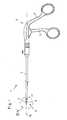
- the medical punch 1 shown completelyconsists essentially of a shaft 2 designed as a hollow shaft, on the proximal end of which a handle 3 is arranged which consists of a rigid grip part 4 and a grip part 5 pivotable relative to the rigid grip part 4.
- a tool tip 6is arranged, which consists of a rigid cutting part 7 and a relative to the rigid cutting part 7 movable cutting part 8, wherein the displaceable cutting part 8 via a displaceably mounted in the shaft 2 push / pull device 9 with the pivotable Handle part 5 of the handle 3 is in operative connection.
- the displaceable cutting part 8 of the tool tip 6 and the pivotable handle part 5 of the handle 3are in operative connection with each other via the push / pull device 9 such that by moving the pivotable handle part 5 of the handle 3, the displaceable cutting part 8 via a shift of push / Pulling device 9 in the direction of the longitudinal axis 10 of the shaft 2 on the rigid cutting part 7 of the tool tip 6 to in a closed punching position or vice versa of the rigid cutting part 7 fort is displaced into an open position.
- the compression of the handle parts 4 and 5 of the handle 3causes a displacement of the push / pull device 9 in the proximal direction and thus a displacement of the displaceable blade part 8 in the in Fig. 2 to 5
- the pressing apart of the handle parts 4 and 5 of the handle 3causes a displacement of the push / pull device 9 in the distal direction and thus a displacement of the displaceable cutting part 8 in the in Fig. 6 illustrated open position of the tool tip 6, in which the displaceable cutting part 8 and the rigid cutting part 7 are furthest away from each other.
- the displaceable blade part 8forms the distal end of the push / pull device 9 displaceably mounted in the hollow shaft 2, wherein the proximal end of the displaceable blade part 8 and the distal end of the push / pull device 9 are non-positively connected to one another To ensure transmission of the axial movement of the push / pull device 9 on the displaceable cutting part 8.
- the rigid cutting part 7can be fastened releasably to the shaft 2 via a coupling mechanism 11 designed as a bayonet connection.
- Fig. 2shows a tool tip 6 according to the prior art with a rigid cutting part 7 and a displaceable cutting part 8, the cutting surfaces 12 are formed at an angle of 45 ° to the longitudinal axis 10 of the shaft 2.
- first embodiment of the anti-tip device 13is formed as formed in the proximal region on the movable cutting part I abutment 14 in the form of a bead on which the rigid cutting part 7 abuts and so fixed the axis parallelism of the cutting parts 7 and 8 to each other.
- the anti-tip 13is formed as arranged in the distal region of the rigid cutting part 7 guide pin 15 which engages in a corresponding receptacle 16 in the sliding cutting part 8 and so the axis parallelism of the cutting parts 7 and 8 to each other in the closed punching position fixed.
- FIG. 5 illustrated third embodiment of the anti-tip device 13is formed as the two cutting parts 7 and 8 in the proximal region encompassing sleeve 17 which fixes the two cutting parts 7 and 8 against each other as an outer pressure ring.
- the rigid cutting part 7in all embodiments consists of a sleeve-shaped proximal part 18 which surrounds the displaceable cutting part 8 and a distal stamped part 19 formed integrally with the sleeve-shaped part 18, wherein in the sleeve-shaped proximal part 18 of the rigid cutting part 7 a guide track 20 for guiding reception of the displaceable cutting part 8 is formed.
- the guide track 20is advantageously designed so that it encloses the outer contour of the male slidable cutting part 8 substantially in a form-fitting manner.
- the positionable guidance of the displaceable cutting part 8 in the guide track 20is in the in 6 and 7 illustrated embodiments, characterized in that laterally outwardly projecting guide elements 21 are formed on the displaceable cutting part 8, which engage in a corresponding receptacle 22 of the guide track 20.
- FIG. 6 illustrated embodiment of the tool tip 6differs from that in the figures Fig. 3 to 5 illustrated embodiments, by the configuration of the cutting surfaces 12. While in the embodiment according to Fig. 6 the cutting surfaces 12 of the cutting parts 7 and 8 are formed parallel to each other and substantially at right angles to the longitudinal axis 10 of the shank 2, the cutting surfaces 12 of the cutting parts 7 and 8 of the embodiments according to Fig. 3 to 5 although also also parallel to each other, but in an angle deviating from the right angle, preferably formed by 45 °, aligned with the longitudinal axis 10 of the shaft 2.
- the rigid cutting part 7 and the movable cutting part 8connected to one another via a sleeve-shaped sleeve 23 pushed onto the sleeve-shaped part 18 of the rigid cutting part 7 to form a structural unit.
- the sleeve 23which connects the displaceable cutting part 8 and the rigid cutting part 7 to form a structural unit simultaneously forms the tilting protection 13, which stabilizes the two cutting parts 7 and 8 against each other and forms a sleeve 17.
- a stop 24 limiting the displaceability of the displaceable cutting part 8 in the distal direction (open position)is formed on the rigid cutting part 7.
- Such a trained medical punch 1is characterized by the fact that it allows a simple and constructive design on the one hand an accurate and easy to dose actuation of the cutting parts 7 and 8 and on the other hand for assembly and cleaning purposes quickly and easily dismantled and reassembled.
Landscapes
- Health & Medical Sciences (AREA)
- Surgery (AREA)
- Life Sciences & Earth Sciences (AREA)
- Biomedical Technology (AREA)
- Medical Informatics (AREA)
- Orthopedic Medicine & Surgery (AREA)
- Oral & Maxillofacial Surgery (AREA)
- Engineering & Computer Science (AREA)
- Dentistry (AREA)
- Heart & Thoracic Surgery (AREA)
- Nuclear Medicine, Radiotherapy & Molecular Imaging (AREA)
- Molecular Biology (AREA)
- Animal Behavior & Ethology (AREA)
- General Health & Medical Sciences (AREA)
- Public Health (AREA)
- Veterinary Medicine (AREA)
- Surgical Instruments (AREA)
Description
Translated fromGermanDie Erfindung betrifft eine medizinische Stanze mit einem hohlen Schaft, einer am distalen Ende des Schaftes angeordneten, aus einem starren Schneidenteil und einem gegenüber der starren Schneidteil verschiebbaren Schneidteil bestehenden Werkzeugspitze sowie mit einer am proximalen Ende des Schaftes angeordneten Handhabe, wobei der verschiebbare Schneidenteil und die Handhabe über eine im hohlen Schaft verschiebbar gelagerte Schub-/Zugeinrichtung miteinander in Wirkverbindung stehen und an der Werkzeugspitze ein die Schneidenteile in ihrer zueinander achsparallelen Ausrichtung stabilisierender Kippschutz angeordnet ist, wobei der starre Schneidenteil (7) aus einem den verschiebbaren Schneidenteil (8) umgreifenden hülsenförmigen proximalen Teil (18) und einem einstückig mit dem hülsenförmigen Teil (18) ausgebildenten distalen Stanzteil (19) besteht.The invention relates to a medical punch with a hollow shaft, a arranged at the distal end of the shaft, consisting of a rigid cutting part and a relative to the rigid cutting part cutting tool existing tip and arranged at the proximal end of the shaft handle, wherein the displaceable blade part and the Handle are operatively connected to one another via a push / pull device which is displaceably mounted in the hollow shaft and a stabilizing anti-tipping device is arranged on the tool tip, wherein the rigid cutting part (7) consists of a sleeve-shaped surrounding the displaceable cutting part (8) proximal part (18) and one formed integrally with the sleeve-shaped part (18) formed distal punched part (19).
Bei medizinischen Stanzen handelt es sich um Schneidwerkzeuge mit einer starren Schneidkante und einer gegenüber der starren Schneidkante verschiebbaren Schneidkante, wobei die beiden Schneidkanten nicht wie bei einer Schere oder dergleichen um einen Drehpunkt gegeneinander verschwenkbar sind, sondern in der Regel horizontal gegeneinander verfahrbar sind.In medical punches are cutting tools with a rigid cutting edge and a relative to the rigid cutting edge slidable cutting edge, the two cutting edges are not pivotable about a pivot about a pivot point as in a scissors or the like, but are usually horizontally against each other.
Bei den aus der Praxis bekannten medizinischen Stanzen ist der Instrumentenschaft als Hohlschaft ausgebildet, in dem eine mit der verschiebbaren Schneidkante verbundene und über die Handhabe antreibbare Schub-/Zugeinrichtung verschiebbar gelagert ist. Diese Stanzen haben sich in der Praxis durchaus bewährt, jedoch kann es in der Praxis, insbesondere bei Stanzen, deren Schneidkanten um 45° gegenüber der Instrumentenlängsachse geneigt ausgebildet sind, zu einem Auseinanderscheren der Schneidkanten kommen, wenn die Schneidkanten in die Stanz- bzw. Schließposition verschoben werden. Dieses Ausscheren der Schneidkanten aus ihrer achsparallelen Ausrichtung zueinander verhindert ein exaktes Betätigen der medizinischen Stanze.In the case of the medical punches known from practice, the instrument shaft is designed as a hollow shaft, in which a push / pull device, which is connected to the displaceable cutting edge and can be driven by the handle, is displaceably mounted. These punches have been well proven in practice, however, it can in practice, especially in punching, the cutting edges are formed inclined by 45 ° relative to the instrument longitudinal axis, come to a mutual shearing of the cutting edges when the cutting edges in the punching or closing position be moved. This Extending the cutting edges from their axis-parallel alignment with each other prevents accurate actuation of the medical punch.
Um die Schneidkanten einer medizinischen Stanze achsparallel zueinander auszurichten, ist beispielsweise aus der
Davon ausgehend liegt der Erfindung dieAufgabe zugrunde, eine medizinische Stanze der eingangs genannten Art so auszugestalten, dass diese bei einfachem Aufbau eine stets exakte Führung der Schneidenteile zueinander gewährleistet.Based on this, the invention has theobject , a medical punch of the type mentioned in such a way that this ensures a simple construction always accurate guidance of the cutting parts to each other.
DieLösung dieser Aufgabenstellung ist erfindungsgemäß dadurch gekennzeichnet, dass der starre Schneidenteil (7) und der verschiebbare Schneidenteil (8) über eine auf den hülsenförmigen Teil (18) des starren Schneidenteils (7) aufschiebbare hülsenförmige Manschette (23) zu einer Baueinheit verbindbar sind und, dass diese Baueinheit über einen am hülsenförmigen Teil (18) des starren Schneidenteils (7) ausgebildeten Kopplungsmechanismus (11) lösbar mit dem hohlen Schaft (2) verbunden ist.Thesolution to thisproblem is inventively characterized in that the rigid cutting part (7) and the displaceable cutting part (8) via a on the sleeve-shaped part (18) of the rigid cutting part (7) slidable sleeve-shaped sleeve (23) are connectable to a unit and in that said structural unit is detachably connected to the hollow shaft (2) via a coupling mechanism (11) formed on the sleeve-shaped part (18) of the rigid cutting part (7).
Durch die erfindungsgemäße Kopplung des starren Schneidenteils mit dem hohlen Schaft über einen am hülsenförmigen Teil ausgebildeten Kopplungsmechanismus, beispielsweise in der Form einer Bajonettverbindung, wird gewährleistet, dass die erfindungsgemäße medizinische Stanze einfach und gut zu reinigen ist und darüber hinaus das Auswechseln der Schneidenteile möglich ist.The inventive coupling of the rigid cutting part with the hollow shaft via a coupling mechanism formed on the sleeve-shaped part, for example in the form of a bayonet connection, ensures that the medical punch according to the invention is simple and easy to clean and moreover the replacement of the cutting parts is possible.
Zur Aufnahme und Führung des verschiebbaren Schneidenteils ist im hülsenförmigen Teil des starren Schneidenteils vorteilhafterweise eine Führungsbahn ausgebildet, die die Außenkontur des aufzunehmenden verschiebbaren Schneidenteils im Wesentlichen formschlüssig umschließt. Die lagegerechte Führung des verschiebbaren Schneidenteils in dieser Führungsbahn kann erfindungsgemäß dadurch stabilisiert werden, dass am verschiebbaren Schneidenteil mindestens ein Führungselement ausgebildet ist, das in eine korrespondierende Aufnahme der Führungsbahn des starren Schneidenteils eingreift.For receiving and guiding the displaceable cutting part, a guide track is advantageously formed in the sleeve-shaped part of the rigid cutting part, which essentially surrounds the outer contour of the displaceable cutting part to be received in a form-fitting manner. The position-oriented guidance of the displaceable cutting part in this guideway can be stabilized according to the invention in that at least one of the displaceable cutting parts Guiding element is formed, which engages in a corresponding receiving the guideway of the rigid cutting part.
Gemäß einer ersten Ausführungsform der Erfindung wird vorgeschlagen, dass der Kippschutz als im proximalen Bereich eines Schneidenteils ausgebildetes Widerlager, beispielsweise in Form einer wulstartigen Erhebung, ausgebildet ist, an dem der andere Schneidenteil anliegt, wodurch sich eine gegenseitige Lagestabilisierung der Schneidenteile zueinander ergibt.According to a first embodiment of the invention, it is proposed that the anti-tipper be formed as an abutment formed in the proximal region of a cutting part, for example in the form of a bead-like elevation, against which the other cutting part abuts, resulting in a mutual stabilization of the position of the cutting parts relative to one another.
Gemäß einer zweiten Ausführungsform der Erfindung wird vorgeschlagen, dass der Kippschutz als im distalen Bereich an einem Schneidenteil angeordneter Führungsstift ausgebildet ist, der in eine entsprechende Aufnahme im anderen Schneidenteil eingreift. Bei dieser Ausgestaltungsform erfolgt die gegenseitige Stabilisierung über ein im Wesentlichen formschlüssiges Ineinandergreifen von Teilbereichen der beiden Schneidenteile.According to a second embodiment of the invention, it is proposed that the anti-tilt device is designed as a guide pin which is arranged on a cutting part in the distal region and which engages in a corresponding receptacle in the other cutting part. In this embodiment, the mutual stabilization takes place via an essentially positive interlocking of partial regions of the two cutting parts.
Mit einer dritten Ausführungsform der Erfindung wird vorgeschlagen, dass der Kippschutz als beide Schneidenteile im proximalen Bereich umgreifende Hülse ausgebildet ist. Diese Art der Ausbildung des Kippschutzes stellt eine besonders einfache konstruktive Maßnahme dar, da die Lagestabilisierung der Schneidenteile ohne besondere konstruktiven Anpassung der Schneidenteile über den äußeren Druckring erfolgt.With a third embodiment of the invention, it is proposed that the anti-tipper be formed as a sleeve encompassing both cutting parts in the proximal region. This type of training of Kippschutzes represents a particularly simple structural measure, since the position stabilization of the cutting parts without special structural adaptation of the cutting parts via the outer pressure ring.
Um weiterhin zu gewährleisten, dass die von der Handhabe auf die Schub-/Zugeinrichtung ausgeübte Axialverschiebung der Schub-/Zugeinrichtung im Wesentlichen spielfrei auf den verschiebbaren Schneidenteil übertragen wird, wird erfindungsgemäß vorgeschlagen, dass der verschiebbare Schneidenteil zumindest kraftschlüssig mit der Schub-/Zugeinrichtung verbunden ist, wobei die Schub-/Zugeinrichtung über das distale Ende des Instrumentenschaftes in den Schaft einsetzbar und aus dem Schaft herausziehbar ist.In order to further ensure that the axial displacement of the push / pull device exerted by the handle on the push / pull device is transmitted essentially free of play to the displaceable cutting part, it is proposed according to the invention that the displaceable cutting part is at least positively connected to the push / pull device is, wherein the push / pull device can be inserted over the distal end of the instrument shaft into the shaft and pulled out of the shaft.
Gemäß einer bevorzugten Ausführungsform der Erfindung wird weiterhin vorgeschlagen, dass der starre Schneidenteil und der verschiebbare Schneidenteil über eine auf den hülsenförmigen Teil des starren Schneidenteils aufschiebbare hülsenformige Manschette zu einer Baueinheit verbindbar sind. Durch diese hülsenförmige Manschette wird der starre Schneidenteil unverlierbar an dem in der Führungsbahn des starren Schneidenteils gelagerten verschiebbaren Schneidenteil festgelegt, wodurch eine Montageeinheit geschaffen wird, die über den am hülsenförmigen proximalen Teil des starren Schneidenteils angeordneten Kopplungsmechanismus am hohlen lnstrumentenschaft festlegbar ist.According to a preferred embodiment of the invention, it is furthermore proposed that the rigid cutting part and the displaceable cutting part can be connected to form a structural unit via a sleeve-shaped sleeve which can be pushed onto the tubular part of the rigid cutting part. Through this sleeve-shaped Cuff, the rigid cutting member is captively fixed to the displaceable cutting member mounted in the guide track of the rigid cutting member, whereby a mounting unit is provided, which is fixable on the hollow instrument shaft via the arranged on the sleeve-shaped proximal portion of the rigid cutting member coupling mechanism.
Die den verschiebbaren Schneidenteil und den starren Schneidenteil zu einer Baueinheit verbindende Manschette bildet gemäß einer praktischen Ausführungsform der Erfindung gleichzeitig dem die beiden Schneidenteile gegeneinander stabilisierenden, als Hülse ausgebildeten Kippschutz.According to a practical embodiment of the invention, the sleeve connecting the displaceable cutting part and the rigid cutting part to form a constructional unit simultaneously forms the tilting protection which stabilizes the two cutting parts against each other and forms a sleeve.
Schließlich wird mit der Erfindung vorgeschlagen, dass am starren Schneidenteil die Verschiebbarkeit des verschiebbaren Schneidenteils in die distale Richtung begrenzender Anschlag ausgebildet ist.Finally, it is proposed with the invention that the displaceability of the displaceable cutting part in the distal direction limiting stop is formed on the rigid cutting part.
Weitere Merkmale und Vorteile der Erfindung ergeben sich anhand der zugehörigen Zeichnungen, in denen mehrere Ausführungsbeispiele einer erfindungsgemäßen medizinischen Stanze nur beispielhaft dargestellt sind, ohne die Erfindung auf diese Ausführungsbeispiele zu beschränken. In den Zeichnungen zeigt:
- Fig. 1
- eine schematische Seitenansicht einer erfindungsgemäßen medizini- schen Stanze;
- Fig.2
- eine vergrößerte Schnittdarstellung des Details II, eine Werkzeugspitze dem Stand der Technik darstellend;
- Fig. 3
- eine vergrößerte Schnittdarstellung des Details III, eine erste erfin- dungsgemäße Ausführungsform einer Werkzeugspitze darstellend ;
- Fig.4
- eine vergrößerte Schnittdarstellung des Details III, eine zweite erfin- dungsgemäße Ausführungsform einer Werkzeugspitze darstellend ;
- Fig. 5
- eine vergrößerte Schnittdarstellung des Details III, eine dritte erfin- dungsgemäße Ausführungsform einer Werkzeugspitze darstellend ;
- Fig. 6
- eine teilweise geschnittene perspektivische Ansicht einer vierten erfin- dungsgemäße Ausführungsform einer Werkzeugspitze in der geöffneten Position und
- Fig.7
- einen Schnitt entlang der Linie VII-VII gemäß
Fig. 6 , jedoch die Werk- zeugspitze in der geschlossenen Position darstellend.
- Fig. 1
- a schematic side view of a medical punch according to the invention;
- Fig.2
- an enlarged sectional view of the detail II, representing a tool tip of the prior art;
- Fig. 3
- an enlarged sectional view of the detail III, a first inventive embodiment of a tool tip representing;
- Figure 4
- an enlarged sectional view of the detail III, a second inventive embodiment of a tool tip representing;
- Fig. 5
- an enlarged sectional view of the detail III, representing a third inventive embodiment of a tool tip;
- Fig. 6
- a partially cutaway perspective view of a fourth inventive embodiment of a tool tip in the open position and
- Figure 7
- a section along the line VII-VII according to
Fig. 6 but showing the tool tip in the closed position.
Die in der Abbildung
Der verschiebbare Schneidenteil 8 der Werkzeugspitze 6 und der verschwenkbare Griffteil 5 der Handhabe 3 stehen über die Schub-/Zugeinrichtung 9 derart in Wirkverbindung miteinander, dass durch das Verstellen des verschwenkbaren Griffteils 5 der Handhabe 3 der verschiebbare Schneidenteil 8 über eine Verlagerung der Schub-/Zugeinrichtung 9 in Richtung der Längsachse 10 des Schaftes 2 auf den starren Schneidenteil 7 der Werkzeugspitze 6 zu in eine geschlossene Stanzposition bzw. umgekehrt von dem starren Schneidenteil 7 fort in eine offene Position verschiebbar ist.The
Bei der dargestellten Ausführungsform bewirkt das Zusammendrücken der Griffteile 4 und 5 der Handhabe 3 eine Verlagerung der Schub-/Zugeinrichtung 9 in die proximale Richtung und somit ein Verschieben des verschiebbaren Schneidenteils 8 in die in
Der Aufbau der Werkzeugspitze 6 mit dem starren Schneidenteil 7 und dem verschiebbaren Schneidenteil 8 ist insbesondere den Detailansichten gemäß
Wie weiterhin aus den Abbildungen 2 bis 6 ersichtlich, ist der starre Schneidenteil 7 über einen als Bajonettverbindung ausgebildeten Kopplungsmechanismus 11 lösbar am Schaft 2 festlegbar.As can further be seen from FIGS. 2 to 6, the
Um die Schneidenteile 7 und 8 in ihrer achsparallelen Lage zueinander zu stabilisieren und deren Auseinanderscheren zu verhindern, ist an jeder der in den Abbildungen
Bei der in
Bei der in
Bei der in
Allen drei dargestellten Ausführungsformen ist gemeinsam, dass durch die Anordnung des Kippschutzes 13 an der Werkzeugspitze 6 das in
Wie weiterhin aus den Abbildungen
Zur Aufnahme und Führung des verschiebbaren Schneidenteils 8 ist die Führungsbahn 20 vorteilhafterweise so ausgebildet, dass sie die Außenkontur des aufzunehmenden verschiebbaren Schneidenteils 8 im Wesentlichen formschlüssig umschließt. Die lagegerechte Führung des verschiebbaren Schneidenteils 8 in der Führungsbahn 20 wird bei den in
Die in
Die Arbeitsweise und Funktionsweise der dargestellten und beschriebenen medizinischen Stanzen 1 ist jedoch völlig unabhängig von der Ausrichtung der Schneidflächen 12 zur Längsachse 10 des Schaftes 2.The operation and operation of the illustrated and described medical punches 1, however, is completely independent of the orientation of the cutting surfaces 12 to the
Um die Montage und Demontage der Werkzeugspitze 6 mit den beiden Schneidteilen 7 und 8 zu erleichtern, sind, wie insbesondere aus
Durch diese hülsenförmige Manschette 23 wird der starre Schneidenteil 7 unverlierbar an dem in der Führungsbahn 20 des starren Schneidenteils 7 gelagerten verschiebbaren Schneidenteil 8 festgelegt, wodurch eine Montageeinheit geschaffen wird, die über den am hülsenförmigen proximalen Teil 18 des starren Schneidenteils 7 angeordneten Kopplungsmechanismus 11 am hohlen Schaft 2 festlegbar ist.Through this sleeve-shaped sleeve 23 of the
Bei der in den Abbildungen
Wie weiterhin aus
Eine solchermaßen ausgebildete medizinische Stanze 1 zeichnet sich dadurch aus, dass sie bei einfachem konstruktivem Aufbau einerseits eine exakte und gut dosierbare Betätigung der Schneidenteile 7 und 8 ermöglicht und andererseits zu Montage- und Reinigungszwecken schnell und einfach zerlegbar und wieder zusammensetzbar ist.Such a trained medical punch 1 is characterized by the fact that it allows a simple and constructive design on the one hand an accurate and easy to dose actuation of the cutting
- 11
- medizinische Stanze 18 hülsenförmiger Teil
medical punch 18 sleeve-shaped part - 22
- Schaft 19 Stanzteil
Shank 19 stamped part - 33
- Handhabe 20 FührungsbahnHandle 20 guideway
- 44
- starrer Griffteil 21 Führungselement
rigid handle 21 guide element - 55
- verschwenkbarer Griffteil 22 Aufnahmepivotable handle
part 22 recording - 66
- Werkzeugspitze 23 ManschetteTool tip 23 Cuff
- 77
- starrer Schneidenteil 24 Anschlagrigid cutting
part 24 stop - 88th
- verschiebbarer Schneidenteilmovable cutting part
- 99
- Schub-/ZugeinrichtungPush / pull device
- 1010
- Längsachselongitudinal axis
- 1111
- Kopplungsmechanismuscoupling mechanism
- 1212
- Schneidflächecutting surface
- 1313
- KippschutzStall prevention
- 1414
- Widerlagerabutment
- 1515
- Führungsstiftguide pin
- 1616
- Aufnahmeadmission
- 1717
- Hülseshell
Claims (10)
- Medical punch having a hollow shaft (2), a tool tip (6) situated at the distal end of the shaft (2) and composed of a fixed cutting part (7) and a cutting part (8) which is displaceable with respect to the fixed cutting part (7), and a handle (3) situated at the proximal end of the shaft (2), wherein the displaceable cutting part (8) and the handle (3) are in operative connection with one another via a push/pull device (9) displaceably supported in the hollow shaft (2), and that an anti-tilt protector (13) which stabilizes the cutting parts (7, 8) in their mutually axially parallel orientation is situated at the tool tip (6), wherein the fixed cutting part (7) is composed of a sleeve-shaped proximal portion (18) which encloses the displaceable cutting part (8), and a distal punching part (19) which is formed in one piece with the sleeve-shaped portion (18),
characterized in that the fixed cutting part (7) and the displaceable cutting part (8) are connectable via a sleeve-shaped collar (23) which may be pushed onto the sleeve-shaped portion (18) of the fixed cutting part (7) to form an integral unit, and that this integral unit is detachably connected to the hollow shaft (2) via a coupling mechanism (11) provided on the sleeve-shaped portion (18) of the fixed cutting part (7). - Medical punch according to Claim 1,characterized in that a guideway (20) for accommodating the displaceable cutting part (8) is formed in the sleeve-shaped portion (18) of the fixed cutting part (7).
- Medical punch according to Claim 2,characterized in that at least the guide element (21) which stabilizes the displaceable cutting part (8) in the guideway (20) is provided at the displaceable cutting part (8).
- Medical punch according to one of Claims 1 through 3,characterized in that the anti-tilt protector (13) is designed as an abutment (14), formed at a cutting part (7 or 8) in the proximal area, against which the other respective cutting part (8 or 7) abuts.
- Medical punch according to one of Claims 1 through 3,characterized in that the anti-tilt protector (13) is designed as a guide pin (15) which is provided at a cutting part (7 or 8) in the distal area, and which engages with a corresponding receptacle (16) in the other respective cutting part (8 or 7).
- Medical punch according to one of Claims 1 through 3,characterized in that the anti-tilt protector (13) is designed as a sleeve (17) which encloses both cutting parts (7, 8) in the proximal area.
- Medical punch according to one of Claims 1 through 6,characterized in that the displaceable cutting part (8) is connected in at least a positive-fit manner to the push/pull device (9).
- Medical punch according to one of Claims 1 through 7,characterized in that the push/pull device (9) is insertable into the shaft (2) and retractable from the shaft (2) via the distal end of the shaft (2).
- Medical punch according to Claim 6,characterized in that the sleeve-shaped collar (23) at the same time is the sleeve (17) which forms the anti-tilt protector (13) and encloses both cutting parts (7, 8) in the proximal area.
- Medical punch according to one of Claims 1 through 9,characterized in that [a] stop (24) which limits the displaceability of the displaceable cutting part (8) in the distal direction is provided at the fixed cutting part (7).
Applications Claiming Priority (1)
| Application Number | Priority Date | Filing Date | Title |
|---|---|---|---|
| DE102009024124ADE102009024124A1 (en) | 2009-06-06 | 2009-06-06 | Medical punch |
Publications (2)
| Publication Number | Publication Date |
|---|---|
| EP2258285A1 EP2258285A1 (en) | 2010-12-08 |
| EP2258285B1true EP2258285B1 (en) | 2013-05-01 |
Family
ID=42731882
Family Applications (1)
| Application Number | Title | Priority Date | Filing Date |
|---|---|---|---|
| EP10005676.1AActiveEP2258285B1 (en) | 2009-06-06 | 2010-06-01 | Medical punch |
Country Status (3)
| Country | Link |
|---|---|
| US (1) | US8702740B2 (en) |
| EP (1) | EP2258285B1 (en) |
| DE (1) | DE102009024124A1 (en) |
Families Citing this family (3)
| Publication number | Priority date | Publication date | Assignee | Title |
|---|---|---|---|---|
| DE102012007648A1 (en)* | 2012-04-18 | 2013-10-24 | Karl Storz Gmbh & Co. Kg | Micro-invasive medical instrument |
| USD759815S1 (en)* | 2014-03-24 | 2016-06-21 | Karl Storz Gmbh & Co. Kg | Cholangiography catheter guide |
| DE102015117731A1 (en)* | 2015-10-19 | 2017-04-20 | Karl Storz Gmbh & Co. Kg | Medical instrument |
Family Cites Families (11)
| Publication number | Priority date | Publication date | Assignee | Title |
|---|---|---|---|---|
| DE2808911C2 (en)* | 1978-03-02 | 1979-11-08 | B. Braun Melsungen Ag, 3508 Melsungen | Punch to remove bone and cartilage |
| US4722338A (en)* | 1983-12-12 | 1988-02-02 | Daniel Farley | Medical instrument for removing bone |
| US4777948A (en)* | 1984-01-16 | 1988-10-18 | Wright David W | Surgical tool |
| DE8518482U1 (en)* | 1985-06-26 | 1985-09-19 | Wenzler, Günther, 7201 Balgheim | Surgical instrument |
| US6200320B1 (en)* | 1989-04-24 | 2001-03-13 | Gary Karlin Michelson | Surgical rongeur |
| US5653713A (en)* | 1989-04-24 | 1997-08-05 | Michelson; Gary Karlin | Surgical rongeur |
| US5484441A (en)* | 1991-06-17 | 1996-01-16 | Koros; Tibor | Rongeur surgical instrument |
| DE9401494U1 (en)* | 1994-01-29 | 1995-06-01 | Weba Medizinmechanik, 78582 Balgheim | Surgical instrument |
| FR2800986B1 (en)* | 1999-11-17 | 2003-01-31 | Emmanuel Favreul | MEDICAL FORCEPS |
| DE10049060A1 (en)* | 2000-10-04 | 2002-04-11 | Peter Mueller | Pair of pincers has two rigid arms angled on front ends of tubular shaft or inner sliding rod, sliding-sleeve, handle, lever and lock. |
| PL212935B1 (en)* | 2006-04-19 | 2012-12-31 | Andrzej Kukwa | Multi-task surgical tool for precise operations, especially laryngological and neurosurgical operations |
- 2009
- 2009-06-06DEDE102009024124Apatent/DE102009024124A1/ennot_activeWithdrawn
- 2010
- 2010-06-01EPEP10005676.1Apatent/EP2258285B1/enactiveActive
- 2010-06-04USUS12/793,964patent/US8702740B2/enactiveActive
Also Published As
| Publication number | Publication date |
|---|---|
| US8702740B2 (en) | 2014-04-22 |
| US20100312265A1 (en) | 2010-12-09 |
| DE102009024124A1 (en) | 2010-12-09 |
| EP2258285A1 (en) | 2010-12-08 |
Similar Documents
| Publication | Publication Date | Title |
|---|---|---|
| EP0860148B1 (en) | Bayonet coupling for the releasable connection of two tubular-shaft instruments or two parts of an instrument | |
| EP2612609B1 (en) | Medical instrument | |
| DE19837258A1 (en) | Device for operating a surgical instrument for anastomosis of hollow organs | |
| DE202007003114U1 (en) | Medical forceps has a removable tool that fits into a retaining sleeve that has a snap action element that prevents rotation | |
| DE202009017470U1 (en) | Surgical instrument for releasably connecting a handpiece with a surgical tool | |
| WO2007031132A1 (en) | Screwdriver for bone screws | |
| EP1363542B1 (en) | Surgical instrument | |
| EP2258285B1 (en) | Medical punch | |
| EP2732778B1 (en) | Medical instrument | |
| DE202011000828U1 (en) | Surgical instrument shaft and surgical instrument | |
| EP3173038B1 (en) | Shaft instrument | |
| EP1629785A2 (en) | Medical forceps | |
| DE20311293U1 (en) | Surgical instrument with tubular shaft, contains flexible transmission comprising sections connected by ball joints | |
| DE202007000427U1 (en) | Surgical handle and surgical instrument | |
| WO2017021469A1 (en) | Handling instrument for a bone anchor | |
| DE102009048600B4 (en) | Instrument for surgical purposes | |
| DE202007000425U1 (en) | Surgical instrument | |
| DE10333342B4 (en) | Surgical tubular shaft instrument | |
| DE102013211368B4 (en) | Endoscopic shaft instrument | |
| EP2502579A1 (en) | Surgical saw blade and surgical saw | |
| DE202009009562U1 (en) | Surgical shift shaft instrument | |
| DE202009013504U1 (en) | Instrument for surgical purposes | |
| DE102007001752B4 (en) | Surgical handle and surgical instrument | |
| DE102014103345A1 (en) | Keyless medical tool coupling | |
| WO2024003216A1 (en) | Surgical instrument and method for taking same apart |
Legal Events
| Date | Code | Title | Description |
|---|---|---|---|
| PUAI | Public reference made under article 153(3) epc to a published international application that has entered the european phase | Free format text:ORIGINAL CODE: 0009012 | |
| AK | Designated contracting states | Kind code of ref document:A1 Designated state(s):AL AT BE BG CH CY CZ DE DK EE ES FI FR GB GR HR HU IE IS IT LI LT LU LV MC MK MT NL NO PL PT RO SE SI SK SM TR | |
| AX | Request for extension of the european patent | Extension state:BA ME RS | |
| 17P | Request for examination filed | Effective date:20110530 | |
| 17Q | First examination report despatched | Effective date:20110801 | |
| GRAP | Despatch of communication of intention to grant a patent | Free format text:ORIGINAL CODE: EPIDOSNIGR1 | |
| GRAS | Grant fee paid | Free format text:ORIGINAL CODE: EPIDOSNIGR3 | |
| GRAA | (expected) grant | Free format text:ORIGINAL CODE: 0009210 | |
| AK | Designated contracting states | Kind code of ref document:B1 Designated state(s):AL AT BE BG CH CY CZ DE DK EE ES FI FR GB GR HR HU IE IS IT LI LT LU LV MC MK MT NL NO PL PT RO SE SI SK SM TR | |
| REG | Reference to a national code | Ref country code:GB Ref legal event code:FG4D Free format text:NOT ENGLISH | |
| REG | Reference to a national code | Ref country code:AT Ref legal event code:REF Ref document number:609390 Country of ref document:AT Kind code of ref document:T Effective date:20130515 Ref country code:CH Ref legal event code:EP | |
| REG | Reference to a national code | Ref country code:IE Ref legal event code:FG4D Free format text:LANGUAGE OF EP DOCUMENT: GERMAN | |
| REG | Reference to a national code | Ref country code:DE Ref legal event code:R096 Ref document number:502010003106 Country of ref document:DE Effective date:20130627 | |
| REG | Reference to a national code | Ref country code:NL Ref legal event code:VDEP Effective date:20130501 | |
| REG | Reference to a national code | Ref country code:LT Ref legal event code:MG4D | |
| PG25 | Lapsed in a contracting state [announced via postgrant information from national office to epo] | Ref country code:SE Free format text:LAPSE BECAUSE OF FAILURE TO SUBMIT A TRANSLATION OF THE DESCRIPTION OR TO PAY THE FEE WITHIN THE PRESCRIBED TIME-LIMIT Effective date:20130501 Ref country code:LT Free format text:LAPSE BECAUSE OF FAILURE TO SUBMIT A TRANSLATION OF THE DESCRIPTION OR TO PAY THE FEE WITHIN THE PRESCRIBED TIME-LIMIT Effective date:20130501 Ref country code:IS Free format text:LAPSE BECAUSE OF FAILURE TO SUBMIT A TRANSLATION OF THE DESCRIPTION OR TO PAY THE FEE WITHIN THE PRESCRIBED TIME-LIMIT Effective date:20130901 Ref country code:ES Free format text:LAPSE BECAUSE OF FAILURE TO SUBMIT A TRANSLATION OF THE DESCRIPTION OR TO PAY THE FEE WITHIN THE PRESCRIBED TIME-LIMIT Effective date:20130812 Ref country code:SI Free format text:LAPSE BECAUSE OF FAILURE TO SUBMIT A TRANSLATION OF THE DESCRIPTION OR TO PAY THE FEE WITHIN THE PRESCRIBED TIME-LIMIT Effective date:20130501 Ref country code:NO Free format text:LAPSE BECAUSE OF FAILURE TO SUBMIT A TRANSLATION OF THE DESCRIPTION OR TO PAY THE FEE WITHIN THE PRESCRIBED TIME-LIMIT Effective date:20130801 Ref country code:FI Free format text:LAPSE BECAUSE OF FAILURE TO SUBMIT A TRANSLATION OF THE DESCRIPTION OR TO PAY THE FEE WITHIN THE PRESCRIBED TIME-LIMIT Effective date:20130501 Ref country code:PT Free format text:LAPSE BECAUSE OF FAILURE TO SUBMIT A TRANSLATION OF THE DESCRIPTION OR TO PAY THE FEE WITHIN THE PRESCRIBED TIME-LIMIT Effective date:20130902 Ref country code:GR Free format text:LAPSE BECAUSE OF FAILURE TO SUBMIT A TRANSLATION OF THE DESCRIPTION OR TO PAY THE FEE WITHIN THE PRESCRIBED TIME-LIMIT Effective date:20130802 | |
| PG25 | Lapsed in a contracting state [announced via postgrant information from national office to epo] | Ref country code:BG Free format text:LAPSE BECAUSE OF FAILURE TO SUBMIT A TRANSLATION OF THE DESCRIPTION OR TO PAY THE FEE WITHIN THE PRESCRIBED TIME-LIMIT Effective date:20130801 Ref country code:PL Free format text:LAPSE BECAUSE OF FAILURE TO SUBMIT A TRANSLATION OF THE DESCRIPTION OR TO PAY THE FEE WITHIN THE PRESCRIBED TIME-LIMIT Effective date:20130501 Ref country code:CY Free format text:LAPSE BECAUSE OF FAILURE TO SUBMIT A TRANSLATION OF THE DESCRIPTION OR TO PAY THE FEE WITHIN THE PRESCRIBED TIME-LIMIT Effective date:20130501 Ref country code:HR Free format text:LAPSE BECAUSE OF FAILURE TO SUBMIT A TRANSLATION OF THE DESCRIPTION OR TO PAY THE FEE WITHIN THE PRESCRIBED TIME-LIMIT Effective date:20130501 | |
| BERE | Be: lapsed | Owner name:KARL STORZ G.M.B.H. & CO. KG Effective date:20130630 | |
| PG25 | Lapsed in a contracting state [announced via postgrant information from national office to epo] | Ref country code:LV Free format text:LAPSE BECAUSE OF FAILURE TO SUBMIT A TRANSLATION OF THE DESCRIPTION OR TO PAY THE FEE WITHIN THE PRESCRIBED TIME-LIMIT Effective date:20130501 | |
| PG25 | Lapsed in a contracting state [announced via postgrant information from national office to epo] | Ref country code:CZ Free format text:LAPSE BECAUSE OF FAILURE TO SUBMIT A TRANSLATION OF THE DESCRIPTION OR TO PAY THE FEE WITHIN THE PRESCRIBED TIME-LIMIT Effective date:20130501 Ref country code:SK Free format text:LAPSE BECAUSE OF FAILURE TO SUBMIT A TRANSLATION OF THE DESCRIPTION OR TO PAY THE FEE WITHIN THE PRESCRIBED TIME-LIMIT Effective date:20130501 Ref country code:MC Free format text:LAPSE BECAUSE OF FAILURE TO SUBMIT A TRANSLATION OF THE DESCRIPTION OR TO PAY THE FEE WITHIN THE PRESCRIBED TIME-LIMIT Effective date:20130501 Ref country code:DK Free format text:LAPSE BECAUSE OF FAILURE TO SUBMIT A TRANSLATION OF THE DESCRIPTION OR TO PAY THE FEE WITHIN THE PRESCRIBED TIME-LIMIT Effective date:20130501 Ref country code:EE Free format text:LAPSE BECAUSE OF FAILURE TO SUBMIT A TRANSLATION OF THE DESCRIPTION OR TO PAY THE FEE WITHIN THE PRESCRIBED TIME-LIMIT Effective date:20130501 | |
| PG25 | Lapsed in a contracting state [announced via postgrant information from national office to epo] | Ref country code:NL Free format text:LAPSE BECAUSE OF FAILURE TO SUBMIT A TRANSLATION OF THE DESCRIPTION OR TO PAY THE FEE WITHIN THE PRESCRIBED TIME-LIMIT Effective date:20130501 Ref country code:RO Free format text:LAPSE BECAUSE OF FAILURE TO SUBMIT A TRANSLATION OF THE DESCRIPTION OR TO PAY THE FEE WITHIN THE PRESCRIBED TIME-LIMIT Effective date:20130501 | |
| PLBE | No opposition filed within time limit | Free format text:ORIGINAL CODE: 0009261 | |
| STAA | Information on the status of an ep patent application or granted ep patent | Free format text:STATUS: NO OPPOSITION FILED WITHIN TIME LIMIT | |
| REG | Reference to a national code | Ref country code:IE Ref legal event code:MM4A | |
| PG25 | Lapsed in a contracting state [announced via postgrant information from national office to epo] | Ref country code:BE Free format text:LAPSE BECAUSE OF NON-PAYMENT OF DUE FEES Effective date:20130630 | |
| 26N | No opposition filed | Effective date:20140204 | |
| PG25 | Lapsed in a contracting state [announced via postgrant information from national office to epo] | Ref country code:IE Free format text:LAPSE BECAUSE OF NON-PAYMENT OF DUE FEES Effective date:20130601 | |
| REG | Reference to a national code | Ref country code:DE Ref legal event code:R097 Ref document number:502010003106 Country of ref document:DE Effective date:20140204 | |
| REG | Reference to a national code | Ref country code:CH Ref legal event code:PL | |
| PG25 | Lapsed in a contracting state [announced via postgrant information from national office to epo] | Ref country code:MT Free format text:LAPSE BECAUSE OF FAILURE TO SUBMIT A TRANSLATION OF THE DESCRIPTION OR TO PAY THE FEE WITHIN THE PRESCRIBED TIME-LIMIT Effective date:20130501 | |
| PG25 | Lapsed in a contracting state [announced via postgrant information from national office to epo] | Ref country code:CH Free format text:LAPSE BECAUSE OF NON-PAYMENT OF DUE FEES Effective date:20140630 Ref country code:LI Free format text:LAPSE BECAUSE OF NON-PAYMENT OF DUE FEES Effective date:20140630 | |
| PG25 | Lapsed in a contracting state [announced via postgrant information from national office to epo] | Ref country code:SM Free format text:LAPSE BECAUSE OF FAILURE TO SUBMIT A TRANSLATION OF THE DESCRIPTION OR TO PAY THE FEE WITHIN THE PRESCRIBED TIME-LIMIT Effective date:20130501 | |
| PG25 | Lapsed in a contracting state [announced via postgrant information from national office to epo] | Ref country code:TR Free format text:LAPSE BECAUSE OF FAILURE TO SUBMIT A TRANSLATION OF THE DESCRIPTION OR TO PAY THE FEE WITHIN THE PRESCRIBED TIME-LIMIT Effective date:20130501 | |
| PG25 | Lapsed in a contracting state [announced via postgrant information from national office to epo] | Ref country code:HU Free format text:LAPSE BECAUSE OF FAILURE TO SUBMIT A TRANSLATION OF THE DESCRIPTION OR TO PAY THE FEE WITHIN THE PRESCRIBED TIME-LIMIT; INVALID AB INITIO Effective date:20100601 Ref country code:MK Free format text:LAPSE BECAUSE OF FAILURE TO SUBMIT A TRANSLATION OF THE DESCRIPTION OR TO PAY THE FEE WITHIN THE PRESCRIBED TIME-LIMIT Effective date:20130501 Ref country code:LU Free format text:LAPSE BECAUSE OF NON-PAYMENT OF DUE FEES Effective date:20130601 | |
| REG | Reference to a national code | Ref country code:FR Ref legal event code:PLFP Year of fee payment:7 | |
| REG | Reference to a national code | Ref country code:AT Ref legal event code:MM01 Ref document number:609390 Country of ref document:AT Kind code of ref document:T Effective date:20150601 | |
| PG25 | Lapsed in a contracting state [announced via postgrant information from national office to epo] | Ref country code:AT Free format text:LAPSE BECAUSE OF NON-PAYMENT OF DUE FEES Effective date:20150601 | |
| REG | Reference to a national code | Ref country code:FR Ref legal event code:PLFP Year of fee payment:8 | |
| REG | Reference to a national code | Ref country code:DE Ref legal event code:R081 Ref document number:502010003106 Country of ref document:DE Owner name:KARL STORZ SE & CO. KG INTELLECTUAL PROPERTY, DE Free format text:FORMER OWNER: KARL STORZ GMBH & CO. KG, 78532 TUTTLINGEN, DE Ref country code:DE Ref legal event code:R082 Ref document number:502010003106 Country of ref document:DE Representative=s name:HOFMEISTER, FRANK, DIPL.-ING., DE Ref country code:DE Ref legal event code:R081 Ref document number:502010003106 Country of ref document:DE Owner name:KARL STORZ SE & CO. KG, DE Free format text:FORMER OWNER: KARL STORZ GMBH & CO. KG, 78532 TUTTLINGEN, DE | |
| REG | Reference to a national code | Ref country code:FR Ref legal event code:PLFP Year of fee payment:9 | |
| PG25 | Lapsed in a contracting state [announced via postgrant information from national office to epo] | Ref country code:AL Free format text:LAPSE BECAUSE OF FAILURE TO SUBMIT A TRANSLATION OF THE DESCRIPTION OR TO PAY THE FEE WITHIN THE PRESCRIBED TIME-LIMIT Effective date:20130501 | |
| P01 | Opt-out of the competence of the unified patent court (upc) registered | Effective date:20230527 | |
| PGFP | Annual fee paid to national office [announced via postgrant information from national office to epo] | Ref country code:IT Payment date:20240619 Year of fee payment:15 | |
| PGFP | Annual fee paid to national office [announced via postgrant information from national office to epo] | Ref country code:DE Payment date:20250626 Year of fee payment:16 | |
| PGFP | Annual fee paid to national office [announced via postgrant information from national office to epo] | Ref country code:GB Payment date:20250617 Year of fee payment:16 | |
| PGFP | Annual fee paid to national office [announced via postgrant information from national office to epo] | Ref country code:FR Payment date:20250624 Year of fee payment:16 |