EP2258274A1 - Surgical clip applier - Google Patents
Surgical clip applierDownload PDFInfo
- Publication number
- EP2258274A1 EP2258274A1EP10179713AEP10179713AEP2258274A1EP 2258274 A1EP2258274 A1EP 2258274A1EP 10179713 AEP10179713 AEP 10179713AEP 10179713 AEP10179713 AEP 10179713AEP 2258274 A1EP2258274 A1EP 2258274A1
- Authority
- EP
- European Patent Office
- Prior art keywords
- end region
- carrier
- distal end
- closure element
- pusher
- Prior art date
- Legal status (The legal status is an assumption and is not a legal conclusion. Google has not performed a legal analysis and makes no representation as to the accuracy of the status listed.)
- Granted
Links
- 210000004204blood vesselAnatomy0.000abstractdescription81
- 238000000034methodMethods0.000abstractdescription17
- 230000023597hemostasisEffects0.000abstractdescription5
- 238000004519manufacturing processMethods0.000abstract1
- 230000007704transitionEffects0.000description19
- 230000002829reductive effectEffects0.000description17
- 239000000463materialSubstances0.000description14
- 230000000717retained effectEffects0.000description13
- 230000003068static effectEffects0.000description9
- 125000006850spacer groupChemical group0.000description7
- 230000008878couplingEffects0.000description6
- 238000010168coupling processMethods0.000description6
- 238000005859coupling reactionMethods0.000description6
- 230000006870functionEffects0.000description5
- 229910052751metalInorganic materials0.000description5
- 239000002184metalSubstances0.000description5
- 230000003213activating effectEffects0.000description4
- 230000000712assemblyEffects0.000description4
- 238000000429assemblyMethods0.000description4
- 238000005381potential energyMethods0.000description4
- 238000007789sealingMethods0.000description4
- 230000009471actionEffects0.000description3
- 238000013459approachMethods0.000description3
- 238000002405diagnostic procedureMethods0.000description3
- 239000012530fluidSubstances0.000description3
- 230000002401inhibitory effectEffects0.000description3
- 230000002093peripheral effectEffects0.000description3
- 238000002560therapeutic procedureMethods0.000description3
- 230000002792vascularEffects0.000description3
- HZEWFHLRYVTOIW-UHFFFAOYSA-N[Ti].[Ni]Chemical compound[Ti].[Ni]HZEWFHLRYVTOIW-UHFFFAOYSA-N0.000description2
- 229910045601alloyInorganic materials0.000description2
- 239000000956alloySubstances0.000description2
- 238000002399angioplastyMethods0.000description2
- 238000002594fluoroscopyMethods0.000description2
- 238000003384imaging methodMethods0.000description2
- 230000000670limiting effectEffects0.000description2
- 230000013011matingEffects0.000description2
- 238000012986modificationMethods0.000description2
- 230000004048modificationEffects0.000description2
- 229910001000nickel titaniumInorganic materials0.000description2
- 230000008569processEffects0.000description2
- 230000002441reversible effectEffects0.000description2
- 206010053567CoagulopathiesDiseases0.000description1
- 206010018852HaematomaDiseases0.000description1
- 208000032843HemorrhageDiseases0.000description1
- 206010052428WoundDiseases0.000description1
- 208000027418Wounds and injuryDiseases0.000description1
- 239000000853adhesiveSubstances0.000description1
- 230000001070adhesive effectEffects0.000description1
- 230000000740bleeding effectEffects0.000description1
- 210000004369bloodAnatomy0.000description1
- 239000008280bloodSubstances0.000description1
- 210000001715carotid arteryAnatomy0.000description1
- 230000035602clottingEffects0.000description1
- 238000010276constructionMethods0.000description1
- 230000008602contractionEffects0.000description1
- 230000000994depressogenic effectEffects0.000description1
- 210000001105femoral arteryAnatomy0.000description1
- 238000002513implantationMethods0.000description1
- 208000014674injuryDiseases0.000description1
- 238000003780insertionMethods0.000description1
- 230000037431insertionEffects0.000description1
- 238000013152interventional procedureMethods0.000description1
- 239000000203mixtureSubstances0.000description1
- 238000012544monitoring processMethods0.000description1
- 230000035515penetrationEffects0.000description1
- 210000005259peripheral bloodAnatomy0.000description1
- 239000011886peripheral bloodSubstances0.000description1
- 230000004044responseEffects0.000description1
- 230000000452restraining effectEffects0.000description1
- 229910001285shape-memory alloyInorganic materials0.000description1
- 230000001225therapeutic effectEffects0.000description1
- 230000000930thermomechanical effectEffects0.000description1
- 230000008733traumaEffects0.000description1
- 210000005166vasculatureAnatomy0.000description1
Images


Classifications
- A—HUMAN NECESSITIES
- A61—MEDICAL OR VETERINARY SCIENCE; HYGIENE
- A61B—DIAGNOSIS; SURGERY; IDENTIFICATION
- A61B17/00—Surgical instruments, devices or methods
- A61B17/064—Surgical staples, i.e. penetrating the tissue
- A—HUMAN NECESSITIES
- A61—MEDICAL OR VETERINARY SCIENCE; HYGIENE
- A61B—DIAGNOSIS; SURGERY; IDENTIFICATION
- A61B17/00—Surgical instruments, devices or methods
- A61B17/0057—Implements for plugging an opening in the wall of a hollow or tubular organ, e.g. for sealing a vessel puncture or closing a cardiac septal defect
- A—HUMAN NECESSITIES
- A61—MEDICAL OR VETERINARY SCIENCE; HYGIENE
- A61B—DIAGNOSIS; SURGERY; IDENTIFICATION
- A61B17/00—Surgical instruments, devices or methods
- A61B17/064—Surgical staples, i.e. penetrating the tissue
- A61B17/0644—Surgical staples, i.e. penetrating the tissue penetrating the tissue, deformable to closed position
- A—HUMAN NECESSITIES
- A61—MEDICAL OR VETERINARY SCIENCE; HYGIENE
- A61B—DIAGNOSIS; SURGERY; IDENTIFICATION
- A61B17/00—Surgical instruments, devices or methods
- A61B17/068—Surgical staplers, e.g. containing multiple staples or clamps
- A—HUMAN NECESSITIES
- A61—MEDICAL OR VETERINARY SCIENCE; HYGIENE
- A61B—DIAGNOSIS; SURGERY; IDENTIFICATION
- A61B17/00—Surgical instruments, devices or methods
- A61B17/064—Surgical staples, i.e. penetrating the tissue
- A61B17/0643—Surgical staples, i.e. penetrating the tissue with separate closing member, e.g. for interlocking with staple
- A—HUMAN NECESSITIES
- A61—MEDICAL OR VETERINARY SCIENCE; HYGIENE
- A61B—DIAGNOSIS; SURGERY; IDENTIFICATION
- A61B17/00—Surgical instruments, devices or methods
- A61B17/12—Surgical instruments, devices or methods for ligaturing or otherwise compressing tubular parts of the body, e.g. blood vessels or umbilical cord
- A61B17/122—Clamps or clips, e.g. for the umbilical cord
- A61B17/1227—Spring clips
- A—HUMAN NECESSITIES
- A61—MEDICAL OR VETERINARY SCIENCE; HYGIENE
- A61B—DIAGNOSIS; SURGERY; IDENTIFICATION
- A61B17/00—Surgical instruments, devices or methods
- A61B17/12—Surgical instruments, devices or methods for ligaturing or otherwise compressing tubular parts of the body, e.g. blood vessels or umbilical cord
- A61B17/128—Surgical instruments, devices or methods for ligaturing or otherwise compressing tubular parts of the body, e.g. blood vessels or umbilical cord for applying or removing clamps or clips
- A61B17/1285—Surgical instruments, devices or methods for ligaturing or otherwise compressing tubular parts of the body, e.g. blood vessels or umbilical cord for applying or removing clamps or clips for minimally invasive surgery
- A—HUMAN NECESSITIES
- A61—MEDICAL OR VETERINARY SCIENCE; HYGIENE
- A61B—DIAGNOSIS; SURGERY; IDENTIFICATION
- A61B17/00—Surgical instruments, devices or methods
- A61B17/0057—Implements for plugging an opening in the wall of a hollow or tubular organ, e.g. for sealing a vessel puncture or closing a cardiac septal defect
- A61B2017/00637—Implements for plugging an opening in the wall of a hollow or tubular organ, e.g. for sealing a vessel puncture or closing a cardiac septal defect for sealing trocar wounds through abdominal wall
- A—HUMAN NECESSITIES
- A61—MEDICAL OR VETERINARY SCIENCE; HYGIENE
- A61B—DIAGNOSIS; SURGERY; IDENTIFICATION
- A61B17/00—Surgical instruments, devices or methods
- A61B17/0057—Implements for plugging an opening in the wall of a hollow or tubular organ, e.g. for sealing a vessel puncture or closing a cardiac septal defect
- A61B2017/00672—Locating means therefor, e.g. bleed back lumen
Definitions
- the present inventionrelates generally to apparatus and methods for closing and/or sealing openings through tissue, and more particularly to apparatus and methods for delivering a closure element for closing a puncture in a blood vessel or other body lumen formed during a diagnostic or therapeutic procedure
- Catheterization and interventional proceduressuch as angioplasty or stenting, generally are performed by inserting a hollow needle through a patient's skin and tissue into the vascular system.
- a guide wiremay be advanced through the needle and into the patient's blood vessel accessed by the needle.
- the needlethen is removed, enabling an introducer sheath to be advanced over the guide wire into the vessel, e.g., in conjunction with or subsequent to a dilator.
- a catheter or other devicemay then be advanced through a lumen of the introducer sheath and over the guide wire into a position for performing a medical procedure.
- the introducer sheathmay facilitate introducing various devices into the vessel, while minimizing trauma to the vessel wall and/or minimizing blood loss during a procedure.
- bleed back indicatorsTo facilitate positioning devices that are percutaneously inserted into a blood vessel, "bleed back" indicators have been suggested.
- U.S. Patent No. 5,676,974issued to Kensey et al. , discloses a bleed back lumen intended to facilitate positioning of a biodegradable plug within a puncture site. This device, however, requires that an anchor of the plug be positioned within the vessel, and therefore, may increase the nsk of over-advancement of the plug itself into the vessel.
- U.S. Patent No. 5,674,231issued to Green et al. , discloses a deployable loop that may be advanced through a sheath into a vessel.
- the loopis intended to resiliently expand to engage the inner wall of the vessel, thereby facilitating holding the sheath in a desired location with respect to the vessel.
- apparatus and methods for delivering a device for closing a vascular puncture site or other opening through tissuewould be useful.
- the present inventionis directed toward an apparatus and method for delivering a closure element through tissue and into an opening formed in, or adjacent to, a wall of a blood vessel or other body lumen of any size.
- the apparatusis configured to receive and retain the closure element such that the closure element is disposed substantially within the apparatus. Thereby, if the apparatus is introduced via an introducer sheath, for example, the closure element can be disposed within, and delivered by way of, a lumen of the introducer sheath.
- the apparatusalso is configured to engage the blood vessel wall adjacent to the opening and to position the closure element substantially adjacent to an outer surface of the blood vessel wall adjacent to the opening.
- the apparatusWhen properly positioned, the apparatus can be activated to distally deploy the closure element.
- the apparatuspreferably is configured to substantially uniformly expand the closure element beyond a natural cross-section of the closure element such that the closure element, when deployed, is configured to engage significant amount of the blood vessel wall 620 and/or tissue 630.
- the closure elementEngaging the blood vessel wall and/or tissue, the closure element is further configured to return to the natural cross-section. Thereby, the engaged blood vessel wall and/or tissue are drawn substantially closed and/or sealed, such that, for example, hemostasis within the opening is enhanced.
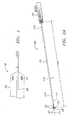
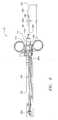
- an apparatusthat is configured to prevent madvertent tissue contact during positioning and to engage a substantial of amount of tissue adjacent to the opening can prove much more desirable and provide a basis for a wide range of medical applications, such as diagnostic and/or therapeutic procedures involving blood vessels or other body lumens of any size. This result can be achieved, according to one embodiment of the present invention, by employing an apparatus 100 as shown in Fig. 1 .
- the apparatus 100can deliver a closure element 500 (shown in Figs. 6A-B ) through tissue 630 (shown in Fig. 8A ) and into an opening 610 (shown in Fig. 8A ) formed in and/or adjacent to a wall 620 (shown in Fig. 8A ) of a blood vessel 600 (shown in Fig. 8A ) or other body lumen.
- the closure element (or clip) 500preferably has a generally annular-shape body 510 (shown in Figs. 6A-B ) defining a channel 540 and one or more barbs and/or tines 520 (shown in Figs.
- the closure element 500has a natural shape and size, the closure element 500 can be deformed into other shapes and sizes, as desired, and is configured to return to the natural shape and size when released.
- the closure element 500can have a natural, planar configuration with opposing tines 520 and a natural cross-section 530 as shown in Figs. 6A-B .
- the natural cross-section 530 of the closure element 500can be reduced to form a reduced closure element 500' that has a natural, planar configuration with opposing tines 520 and a reduced cross-section 530' as shown in Figs. 6C-D .
- the reduced closure element 500'can be further deformed to form a substantially tubular closure element 500" (shown in Fig. 6F ) having the reduced cross-section 530' as well as being in a substantially tubular configuration with the tines 520 in an axial configuration.
- the closure element 500can be formed from any suitable material, including any biodegradable material, any shape memory alloy, such as alloys of nickel-titanium, or any combination thereof.
- the closure element 500can include radiopaque markers (not shown) or may be wholly or partially formed from a radiopaque material to facilitate observation of the closure element 500 using fluoroscopy or other imaging systems. Exemplary embodiments of a closure element are disclosed in U.S. Patent No. 6,197,042 , in co-pending applications Serial Nos. 09/546,998 , 09/610,238 , and 10/081,726 . The disclosures of these references and any others cited therein are expressly incorporated herein by reference.
- the apparatus 100is configured to receive and retain the closure element 500 such that the closure element 500 is disposed substantially within the apparatus 100. Thereby, if the apparatus 100 is introduced via an introducer sheath 640 (shown in Fig. 8A ), for example, the closure element 500 can be disposed within, and delivered by way of, a lumen 644 (shown in Fig. 8A ) of the introducer sheath 640.
- the apparatus 100also is configured to engage the blood vessel wall 620 adjacent to the opening 610. Being disposed substantially within the apparatus 100, the closure element 500 can deeply penetrate, without inadvertently contacting, tissue 630 adjacent to the opening 610 such that the apparatus 100 can position the closure element 500 substantially adjacent to an outer surface 620a (shown in Fig. 8A ) of the blood vessel wall 620 adjacent to the opening 610.
- the apparatus 100can be activated to distally deploy the closure element 500.
- the apparatus 100can deploy the closure element 500 without expanding the closure element 500.
- the closure element 500when deployed, is configured to engage significant amount of the blood vessel wall 620 and/or tissue 630 adjacent to the opening 610. Engaging the blood vessel wall 620 and/or tissue 630, the closure element 500 is further configured to return to the natural cross-section 530.
- the engaged blood vessel wall 620 and/or tissue 630are drawn substantially closed and/or sealed, such that, for example, hemostasis within the opening 610 is enhanced.
- the apparatus 100can be provided as via one or more integrated components and/or discrete components.
- the apparatus 100can comprise a locator (or obturator) assembly 200 and a carrier assembly 300.
- the locator assembly 200 and the carrier assembly 300are shown in Fig. 1 as comprising substantially separate assemblies.
- the locator assembly 200 and the carrier assembly 300each can be provided, in whole or in part, as one or more integrated assemblies.
- the locator assembly 200can selectably engage the inner surface 620b of the blood vessel wall 620 adjacent to the opening 610. Thereby, the locator assembly 200 is configured to draw the blood vessel wall 620 taut and can maintain the proper position of the apparatus 100 as the blood vessel 600 pulsates.
- the locator assembly 200can be provided in the manner disclosed in co-pending applications Serial Nos. 09/732,835 and 10/081,723 , the disclosure of which is expressly incorporated herein by reference, and preferably includes a flexible or semi-rigid tubular body 210, such as an elongate rail, with a longitudinal axis 216. As illustrated in Fig.
- the tubular body 210has a proximal end region 210a and a distal end region 210b and includes a predetermined length 218a and a predetermined outer cross-section 218b, both of which can be of any suitable dimension.
- the distal end region 210b of the locator assembly 200preferably includes a substantially rounded, soft, and/or flexible distal end or tip 220 to facilitate atraumatic advancement and/or retraction of the distal end region 210b into the blood vessel 600.
- a pigtail(not shown) may be provided on the distal end 220 to further aid atraumatic advancement of the distal end region 210b.
- the distal end region 210b of the locator assembly 200further is selectably controllable between an unexpanded state and an expanded state.
- the distal end region 210bIn the unexpanded state, the distal end region 210b has an unexpanded size; whereas, the distal end region 210b in the expanded state has an expanded size, which is greater than the unexpanded size of the distal end region 210b in the unexpanded state.
- the distal end region 210bis configured to expand from the unexpanded size to the expanded size and/or to contract from the expanded size to the unexpanded size, and the expansion and contraction of the distal end region 21 0b preferably is substantially uniform about the longitudinal axis 216.
- one or more expansion elements 230can be provided on the distal end region 210b and can be configured to expand substantially transversely with respect to a longitudinal axis 216 of the locator assembly 200.
- the expansion elements 230may include radiopaque markers (not shown) or may be wholly or partially formed from a radiopaque material to facilitate observation of the expansion elements 230 and/or the distal end region 210b using fluoroscopy or other imaging systems.
- At least one, and preferably all, of the expansion elements 230can comprise a substantially flexible member 230' with a substantially fixed end region 230a', an intermediate region 230b', and a movable end region 230c' as shown in Figs. 2B-C .
- the fixed end region 230a'is fixedly coupled with the distal end region 210b; whereas, the movable end region 230c' is movably coupled with the distal end region 210b and configured to be axially movable relative to the fixed end region 230a'.
- the intermediate regions 230b'buckle and/or expand transversely outwardly, thereby transitioning the distal end region 210b of the locator assembly 200 from the unexpanded state to the expanded state.
- the distal end region 210btransitions from the expanded state to the unexpanded state as each of the movable end regions 230c' are axially moved away from the relevant fixed end region 230a'.
- the expansion elements 230are shown as comprising the flexible members 230' in Figs. 2B-C for purposes of illustration, it is understood that the expansion elements 230 can comprise any type of expansion elements and are not limited to the illustrated embodiments.
- the locator assembly 200also can include a locator control system 240 that is coupled with the proximal end region 210a of the locator assembly 200 and that is configured to selectively control the distal end region 210b of the locator assembly 200 between the unexpanded and expanded states.
- the locator control system 240can selectively control the distal end region 210b between the unexpanded and expanded states, such as by being activated by a switching system (not shown).
- a control member 250such as a rod, wire, or other elongate member, can be moveably disposed within a lumen (not shown) formed by the tubular body 210 and extending substantially between the proximal end region 210a and the distal end region 210b.
- the control member 250has a proximal end region 250a that is coupled with the locator control system 240, preferably via a control block 260 (shown in Fig. 4D ), and a distal end region (not shown) that is coupled with the distal end region 210b of the locator assembly 200, the expansion elements 230, and/or the movable end regions 230c' of the substantially flexible members 230'.
- the locator control system 240can selectively transition the distal end region 210b, the expansion elements 230, and/or the substantially flexible members 230' between the unexpanded and expanded states by moving the control member 250 axially relative to the tubular body 210.
- the locator control system 240preferably includes a locator release system 490 for maintaining the unexpanded state and/or the expanded state of the distal end region 210b, the expansion elements 230, and/or the substantially flexible members 230'.
- the locator release system 490can comprise any type of locking system and can be engaged, for instance, by activating the switching system.
- the locator release system 490can secure the control member 250 to prevent axial movement relative to the tubular body 210, thereby maintaining the substantially flexible members 230' in the expanded state.
- the locator control system 240also can be configured to disengage the locator release system 490, such that the distal end region 210b, the expansion elements 230, and/or the substantially flexible members 230' can transition between the unexpanded and expanded states.
- the locator release system 490can be disengaged, for example, by activating an emergency release system (not shown).
- the locator control system 240can further include a biasing system (not shown), such as one or more springs, to bias the distal end region 210b, the expansion elements 230, and/or the substantially flexible members 230' to enter and/or maintain the unexpanded state when the locator release system 490 is disengaged.
- the carrier assembly 300is coupled with, and slidable relative to, the locator assembly 200.
- the carrier assembly 300is configured to receive and retain the closure element 500 (shown in Figs. 6A-B ), which preferably is disposed substantially within the carrier assembly 300.
- the locator assembly 200engages the inner surface 620b (shown in Fig. 8A ) of the blood vessel wall 620 (shown in Fig. 8A )
- the carrier assembly 300is further configured to position the closure element 500 substantially adjacent to the opening 610 (shown in Fig. 8A ) and to deploy the closure element 500.
- the closure element 500can maintain the reduced cross-section 530' (shown in Figs.
- the closure element 500when deployed, can engage significant amount of the blood vessel wall 620 and/or tissue 630 adjacent to the opening 610. Thereafter, the closure element 500 is configured to return to the natural cross-section 530, preferably substantially uniformly, such that the blood vessel wall 620 and/or tissue 630 is drawn substantially closed and/or sealed.
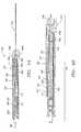
- the carrier assembly 300can include a tube set 305, comprising a carrier member 310, a pusher member 320, and a cover member 330.
- the carrier member 310, the pusher member 320, and the cover member 330can be provided as a plurality of nested, telescoping members with a common longitudinal axis 350 as illustrated in Fig. 3A .
- the carrier member 310is configured to receive and support the closure element 500. While being disposed on the carrier member 310, the closure element 500 preferably is deformed from the natural, planar configuration to form the substantially tubular closure element 500" (shown in Figs. 6F-G ) as will be discussed in more detail below. Being disposed substantially about, and supported by, an outer periphery 312b of the carrier member 310, the substantially tubular closure element 500" can be substantially in axial alignment with the carrier member 310 with the tines 520 pointed substantially distally.
- the carrier member 310has a proximal end region 310a and a distal end region 310b and includes a predetermined length 318a and a predetermined cross-section 318b, both of which can be of any suitable dimension.
- the carrier member 310also can define a lumen 314 that extends substantially between the proximal end region 310a and the distal end region 310b and that is configured to slidably receive at least a portion of the tubular body 210 of the locator assembly 200.
- the distal end region 310b of the carrier member 310preferably has a cross-section that increases distally, as illustrated in Figs. 3A-B , for substantially uniformly expanding the substantially tubular closure element 500" beyond the natural cross-section 530 of the closure element 500 when the substantially tubular closure element 500" is deployed.
- the distal end region 310bcan be formed with a cross-section (not shown) that is substantially uniform.
- the distal end region 310b of the carrier member 310can be provided with the substantially-uniform cross-section and that the substantially tubular closure element 500" can be deployed without being expanded.
- the pusher member 320Being configured to distally deploy the substantially tubular closure element 500", the pusher member 320 has a proximal end region 320a and a distal end region 320b and is coupled with, and slidable relative to, the carrier member 310.
- the pusher member 320includes a predetermined length 328a and a predetermined cross-section 328b, both of which can be of any suitable dimension and can be configured to slidably receive the carrier member 310 such that the distal end region 320b of the pusher member 320 is offset proximally from the distal end region 310b of the carrier member 310.
- the predetermined length 328a of the pusher member 320can be greater than or substantially equal to the predetermined length 318a of the carrier member 310.
- the predetermined length 328a of the pusher member 320however preferably is less than the predetermined length 318a of the carrier member 310 such that the carrier member 310 and the pusher member 320 at least partially define a space 360 distal to the distal end region 320b of the pusher member 320 and along the periphery 312b of the carrier member 310.
- the pusher member 320preferably is substantially tubular and can define a lumen 324 that extends substantially between the proximal end region 320a and the distal end region 320b and that is configured to slidably receive at least a portion of the carrier member 310.
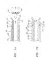
- the cross-section 328b of the pusher member 320preferably is substantially uniform, and the distal end region 320b of the pusher member 320 can comprise one or more longitudinal extensions 325, which extend distally from the pusher member 320 and along the periphery 312b of the carrier member 310 as shown in Fig. 3C .
- the longitudinal extensions 325preferably are biased such that the longitudinal extensions 325 extend generally in parallel with common longitudinal axis 350.
- the longitudinal extensions 325are sufficiently flexible to expand radially, and yet sufficiently rigid to inhibit buckling, as the distal end region 320b is directed distally along the carrier member 310 and engage the distally-increasing cross-section of the distal end region 310b of the carrier member 310 to deploy the substantially tubular closure element 500".
- the cover member 330is configured to retain the substantially tubular closure element 500" substantially within the carrier assembly 300 prior to deployment. Being coupled with, and slidable relative to, the pusher member 320, the cover member 330 has a proximal end region 330a and a distal end region 330b and includes a predetermined length 338a and a predetermined cross-section 338b, both of which can be of any suitable dimension. Preferably being formed as a substantially rigid, semi-rigid, or flexible tubular member, the cover member 330 has an inner periphery 332a and an outer periphery 332b and can define a lumen 334.
- the lumen 334extends substantially between the proximal and distal end regions 330a, 330b of the cover member 330 and can be configured to slidably receive at least a portion of the pusher member 320.
- the distal end region 330bis configured to extend over the space 360, thereby defining an annular cavity 370 for receiving and retaining the substantially tubular closure element 500".
- the cross-section 338b of the cover member 330preferably is substantially uniform, and the distal end region 330b of the cover member 330 preferably comprises one or more longitudinal extensions 335, which extend distally from the cover member 330 and along an outer periphery 322b of the pusher member 320 as shown in Fig. 3D .
- the longitudinal extensions 335can extend generally in parallel with common longitudinal axis 350, the longitudinal extensions 335 preferably are biased such that the plurality of longitudinal extensions 335 extend substantially radially inwardly as illustrated in Figs. 3A and 3D .
- the longitudinal extensions 335can at least partially close the lumen 334 substantially adjacent to the distal end region 330b of the cover member 330.
- the longitudinal extensions 335preferably are sufficiently flexible to expand radially to permit the distal end region 310b of the carrier member 310 to move distally past the cover member 330 to open the annular cavity 370 such that the distal end region 330b no longer extends over the space 360.
- the carrier member 310is at least partially disposed within, and slidable relative to, the lumen 324 of the pusher member 320.
- the pusher member 320is at least partially disposed within, and slidable relative to, the lumen 334 of the cover member 330.
- the tubular body 210 of the locator assembly 200is at least partially disposed within, and slidable relative to, the lumen 314 of the carrier member 310.
- the longitudinal axis 216 of the locator assembly 200preferably is substantially in axial alignment with the common longitudinal axis 350 of the carrier member 310, the pusher member 320, and the cover member 330.
- the tube set 305preferably also includes a support member 340 as shown in Figs. 3A and 3E .
- the support member 340is configured to slidably receive the tubular body 210 of the locator assembly 200 and to provide radial support for the distal end region 210b of the tubular body 210 when the locator assembly 200 is coupled with the carrier assembly 300.
- the carrier assembly 300can advantageously include the support member 340, for example, if the tubular body 210 is not sufficiently rigid or under other circumstances in which support for the tubular body 210 might be desirable.
- the support member 340also can be configured to inhibit the plurality of longitudinal extensions 335, which extend from the distal end region 330b of the cover member 330, from expanding prematurely when the closure element 500 is deployed.
- the support member 340Preferably being formed as a substantially rigid, semi-rigid, or flexible tubular member, the support member 340 includes a proximal end region 340a and a distal end region 340b. Having an outer periphery 342b, the support member 340 can define a lumen 344 that extends substantially between the proximal end region 340a and the distal end region 340b and that is configured to slidably receive and support at least a portion of the tubular body 210 of the locator assembly 200.
- the support member 340in turn, can be at least partially slidably disposed within the lumen 314 of the carrier member 310 such that the tubular body 210 of the locator assembly 200 is coupled with, and slidable relative to, the carrier member 310 in the manner described in more detail above.
- the support member 340has a predetermined length 348a and a predetermined cross-section 348b, both of which can be of any suitable dimension, and the cross-section 348b preferably is substantially uniform. Although shown and described as being substantially separate for purposes of illustration, it will be appreciated that the carrier member 310, the pusher member 320, the cover member 330, and/or the support member 340 can be provided, in whole or in part, as one or more integrated assemblies.
- the carrier assembly 300also can include a housing 380 as illustrated in Fig. 4A .
- the housing 380Preferably being formed as an elongate member with a longitudinal axis 386, the housing 380 has an outer periphery 382b and includes a proximal end region 380a and a distal end region 380b.
- the tubular body 210 of the locator assembly 200at least partially disposed within, and slidable relative to, the tube set 305 such that the distal end region 210b of the tubular body 210 extends beyond the distal end regions 310b, 320b, 330b, and/or 340b.
- the tubular body 210, the carrier member 310, the pusher member 320, the cover member 330, and, if provided, the support member 340are at least partially disposed within, and slidable relative to, the housing 380, and the respective distal end regions 210b, 310b, 320b, 330b, and 340b extend from the distal end region 380b of the housing 380 such that the common longitudinal axis 350 (shown in Fig. 3A ) of the tube set 305 is substantially axially aligned with the longitudinal axis 386 of the housing 380.
- the housing 380supports the tube set 305 and can have one or more handles 390 to facilitate use of the apparatus 100.
- the handles 390extend substantially radially from the outer periphery 382b of the housing 380 and can be provided in the manner known in the art.
- the tubular body 210 of the locator assembly 200is at least partially disposed within, and slidable relative to, the tube set 305 of the carrier assembly 300 such that the distal end region 210b of the tubular body 210 extends beyond the distal end regions 310b, 320b, 330b, and/or 340b.
- the proximal end region 210a of the tubular body 210 and the proximal end regions 310a, 320a, 330a, and/or 340a of the tube set 305are at least partially disposed within, and slidable relative to, the housing 380.
- the switching system of the locator assembly 200 and a switching system 450 of the triggering system 400preferably are accessible external to the housing 380 as shown in Fig. 4A .
- a triggering system 400can be disposed substantially within the housing 380.
- the triggering system 400is configured to control the relative axial movement and/or positioning of the respective distal end regions 310b, 320b, 330b, and 340b of the tube set 305 and/or the distal end region 210b of the locator assembly 200. Being coupled with the proximal end regions 210a, 310a, 320a, 330a, and/or 340a, the triggering system 400 can control the relative axial movement of the distal end regions 210b, 310b, 320b, 330b, and/or 340b in any manner, such as by being activated by the switching system 450.
- the triggering system 400can induce axial motion, such as distal motion, with respect to one or more of the distal end regions 210b, 310b, 320b, 330b, and/or 340b.
- One or more of the distal end regions 210b, 310b, 320b, 330b, and/or 340bcan be axially moved.
- Axial motion of one or more of the carrier member 310, the pusher member 320, the cover member 330, and the support member 340 and/or the tubular body 210can be attained, for example, by applying an axial force to the switching system 450.
- one or more of the distal end regions 210b, 310b, 320b, 330b, and/or 340bmay include radiopaque markers (not shown) or may be wholly or partially formed from a radiopaque material.
- the triggering system 400is configured to overcome internal resistance such that the relative axial movement and/or positioning of the respective distal end regions 310b, 320b, 330b, and 340b of the tube set 305 and/or the distal end region 210b of the locator assembly 200 are controlled in accordance with a predetermined manner when the triggering system 400 is activated. Thereby, movement and/or positioning of the distal end regions 310b, 320b, 330b, 340b, and/or 210b is initiated when at least a predetermined quantity of force is applied to the switching system 450.
- a force that is less than the predetermined quantitygenerally is insufficient to activate the triggering system 400; whereas, when the force increases to a level that is greater than or substantially equal to the predetermined quantity, the triggering system 400 is configured to activate, moving and/or positioning the distal end regions 310b, 320b, 330b, 340b, and/or 210b in accordance with the predetermined manner.
- the triggering system 400once activated, preferably continues to move and/or position the distal end regions 310b, 320b, 330b, 340b, and/or 210b in accordance with the predetermined manner until the closure element 500 is deployed.
- the triggering system 400can comprise one or more sets of cooperating detents for coupling the axial motion of the distal end regions 310b, 320b, 330b, and 340b in accordance with a predetermined manner when the triggering system 400 is activated.
- detentsrefers to any combination of mating elements, such as blocks, tabs, pockets, slots, ramps, locking pins, cantilevered members, support pins, and the like, that may be selectively or automatically engaged and/or disengaged to couple or decouple the carrier member 310, the pusher member 320, the cover member 330, and the support member 340 relative to one another.
- the cooperating detents as illustrated and described beloware merely exemplary and not exhaustive.
- the cooperating detentscan include a first set of cooperating blocks and pockets for releasable coupling the support member 340, the carrier member 310, the pusher member 320, and the cover member 330.
- the support member 340can be decoupled from the carrier member 310, the pusher member 320, and the cover member 330 and preferably is substantially inhibited from further axial movement. Thereby, the carrier member 310, the pusher member 320, and the cover member 330 may continue to be directed distally as the support member 340 remains substantially stationary.
- the cooperating detentscan comprise a carrier block 410, a pusher block 420, a cover block 430, and a support block 440, which can be configured to couple and decouple in accordance with the predetermined manner.
- the carrier block 410is disposed on the proximal end region 310a of the carrier member 310 and includes a carrier pin 412c that extends from the carrier block 410; whereas, the proximal end region 330a of the cover member 330 and the proximal end region 340a the support member 340 are respectively coupled with the cover block 430 and the support block 440.
- a cover pin 432bextends from the cover block 430, and the support block 440 has a support pin 442a, which extends from the support block 440,
- the support pin 442a, the cover pin 432b, and the carrier pin 412ceach preferably are formed from a substantially rigid material, such as an alloy of nickel-titanium.
- the pusher block 420is disposed on the proximal end region 320a of the pusher member 320 and forms a support slot 422a, a cover slot 422b, and a carrier slot 422c.
- the support slot 422ais configured to receive and releasable engage the support pin 442a by which the support member 340 can be coupled with, and decoupled from, the pusher member 320.
- the cover member 330can be coupled with, and decoupled from, the pusher member 320 via the cover slot 422b, which is configured to receive and releasable engage the cover pin 432b.
- the carrier slot 422cis configured to receive and releasable engage the carrier pin 412c such that the carrier member 310 can be coupled with, and decoupled from, the pusher member 320.
- the carrier block 410, the pusher block 420, the cover block 430, and the support block 440preferably are respectively disposed substantially on the outer peripheries 312b, 322b, 332b, and 342b and can be configured to couple and decouple in accordance with the predetermined manner.
- the triggering system 400also includes one or more stops for engaging the pusher block 420, the cover block 430, and/or the support block 440, respectively.
- a support stop 460a, a cover stop 460b, and a carrier stop 460ceach are formed in the housing 380 and are configured to receive, and substantially inhibit further movement of, the support block 440, the cover block 430, and the carrier block 410, respectively, in accordance with the predetermined manner.
- the cover block 430moves distally within the housing 380, and the cover block 430 approaches the cover stop 460b.
- the cover block 430Upon being received by the cover stop 460b, the cover block 430 is substantially locked in place, substantially preventing any further motion by the cover block 430.
- the cover pin 412bResisting the axial force, the cover pin 412b provides a static load while the axial force is less than the predetermined quantity of force. As the axial force increases to a level that is greater than or substantially equal to the predetermined quantity, the cover pin 412b can be displaced from the cover slot 422b, decoupling the cover member 330 from the carrier member 310, the pusher member 320, and the support member 340.
- the static forces provided by the pins 412a, 412b, and 412cis approximately proportional to a composition and cross-section of the respective pins 412a, 412b, and 412c and/or a depth and a slope of the respective slots 422a, 422b, and 422c.
- the pins 412a, 412b, and 412ccan be configured to provide static loads that are differing and/or substantially uniform.
- the triggering system 400can further have a tube release system 470 for inhibiting inadvertent advancement of the tube set 305.
- the tube release system 470is coupled with a tube release member 480, such as a rod, wire, or other elongate member.
- the tube release member 480has a proximal end region 480a that is disposed substantially between the pusher block 420 and the housing 380 (shown in Fig. 4A ) and a distal end region 480b that is coupled with the tube release system 470.
- a tab 485is coupled with the proximal end region 480a of the tube release member 480, and a pin (not shown) extends from the pusher block 420 and is disposed substantially between the tab 485 and a groove (not shown) formed in the housing 380.
- the tube release system 470is configured to release the tube set 305 when the tube release member 480 is moved proximally, freeing the pusher block 420.
- a locator release system 490 for permitting the distal end region 210b, the expansion elements 230, and/or the substantially flexible members 230' of the locator assembly 200 to transition from the expanded state to the unexpanded statecan be included with the triggering system 400.
- the locator release system 490can comprise a rod, wire, or other elongate member and has a proximal end region 490a and a distal end region 490b.
- the proximal end region 490a of the locator release system 490can be coupled with, and configured to activate, the locator control system 240 (shown in Fig. 2D ), and the distal end region 490b extends beyond the pusher block 420.
- the control block 260is disengaged such that the distal end region 210b, the expansion elements 230, and/or the substantially flexible members 230' of the locator assembly 200 to transition from the expanded state to the unexpanded state.
- Figs. 5A-CThe operation of the triggering system 400 in accordance with one predetermined manner is illustrated in Figs. 5A-C with the closure element 500 (shown in Figs. 6A-B ) disposed substantially within the apparatus 100.
- the distal end region 210b of the locator assembly 200has been positioned as desired and has transitioned from the unexpanded state to the expanded state.
- the locator control system 240(shown in Fig. 2D ) maintains the distal end region 210b in the expanded state, a distally-directed axial force is applied to the triggering system 400 via the switching system 450.
- the tube release member 480shown in Fig.
- the tube set 305is substantially freely slidable within the housing 380 and responds to the axial force by sliding distally from an initial predetermined position to a first predetermined position.
- the carrier member 310, the pusher member 320, the cover member 330, and the support member 340are coupled via the slots 422c, 422b, and 422a (shown in Fig. 4C ) and the pins 412c, 422b, and 442a (shown in Fig. 4C ).
- the support pin 442a, the cover pin 432b, and the carrier pin 412care respectively disposed within, and engaged by, the support slot 422a, the cover slot 422b, and the carrier slot 422c such that the carrier block 410, the pusher block 420, the cover block 430, and the support block 440 are coupled as illustrated in Fig. 4C . Therefore, the carrier member 310, the pusher member 320, the cover member 330, and the support member 340 each slide distally from the initial predetermined position to the first predetermined position in response to the axial force.
- Fig. 5Billustrates the positions of the carrier member 310, the pusher member 320, the cover member 330, and the support member 340 upon reaching the first predetermined position.
- the support block 440 and the cover block 430respectively engage the support stop 460a and the cover stop 460b.
- the support stop 460areceives, and substantially inhibits further movement of, the support block 440 and, therefore, the support member 340;
- the cover stop 460breceives, and substantially inhibits further movement of, the cover block 430 and, therefore, the cover member 330.
- the support block 440 and the cover block 430preferably engage the support stop 460a and the cover stop 460b in the first predetermined position
- the support block 440can engage the support stop 460a and the cover block 430 can engage the cover stop 460b in different predetermined positions.
- the predetermined mannercan comprise any number of predetermined positions, each predetermined position being associated with any number of the blocks 410, 420, 430, and 440 engaging any number of relevant stops 460a, 460b, and 460c.
- the carrier member 310 and the pusher member 320can be decoupled from the cover member 330 and the support member 340 by disengaging the support pin 442a and the cover pin 432b from the support slot 422a and the cover slot 422b, respectively.
- the support pin 442a and the cover pin 432beach resist the axial force. While the axial force is less than the combined static force provided by the support pin 442a and the cover pin 432b, the carrier member 310 and the pusher member 320 remain coupled with the cover member 330 and the support member 340.
- the support pin 442a and the cover pin 432bare respectively displaced from the support slot 422a and the cover slot 422b, decoupling the carrier member 310 and the pusher member 320 from the cover member 330 and the support member 340.
- the cover member 330 and the support member 340preferably are inhibited from further distal movement and remain substantially stationary; whereas, the carrier member 310 and the pusher member 320 proceed distally toward a second predetermined position.
- the pusher member 320 and the carrier member 310continue distally until the second predetermined position is reached as shown in Fig. 5C .
- the carrier block 410engages the carrier stop 460c.
- the carrier stop 460creceives, and substantially inhibits further movement of, the carrier block 410 and, therefore, me carrier member 310.
- the pusher member 320can be decoupled from the carrier member 310 by disengaging the carrier pin 412c from the carrier slot 422c.
- the carrier pin 412cresists the axial force. While the axial force is less than the static force provided by the carrier pin 412c, the pusher member 320 remains coupled with the carrier member 310.
- the carrier pin 412cis displaced from the carrier slot 422c, decoupling the pusher member 320 from the carrier member 310.
- the carrier member 310preferably is inhibited from further distal movement and remains substantially stationary; whereas, the pusher member 320 proceed distally to deploy the closure element 500 and to activate the locator release system 490 (shown in Fig. 2D ) such that the distal end region 210b, the expansion elements 230, and/or the substantially flexible members 230' of the locator assembly 200 transition from the expanded state to the unexpanded state.
- the axial force that is applied to overcome the static force associated with the first predetermined positionis sufficient to overcome the static forces associated with the subsequent predetermined positions, to deploy the closure element 500, and to activate the locator release system 490 such that the triggering system 400 operates in one substantially-continuous motion.
- the triggering system 400can include an energy storing element (not shown), which can be disposed substantially between the housing 380 and the blocks 410, 420, 430, and 440 and which is configured to store potential energy for moving the tube set 305 from the initial predetermined position through the other predetermined positions, deploying the closure element 500, and/or activating the locator release system 490.
- the energy storing elementis configured store the potential energy when the tube set 305 is in the initial predetermine position and to release the potential energy, when activated, such that the tube set 305 travels through the predetermined positions at a substantially constant and continuous rate.
- the energy storing elementcan comprise one or more springs (not shown). Each of the springs can be in a compressed state when the tube set 305 is in the initial predetermined position and released from the compressed state when the switching system 450 of the triggering system 400 is activated.
- the closure element 500is disposed within the carrier assembly 300.
- the reduced closure element 500'can be slidably received over the distally-increasing cross-section 318b of the distal end region 310b of the carrier member 310 and disposed about the periphery 312 of the carrier member 310 adjacent to the space 360. Since the reduced cross-section 530' of the reduced closure element 500' is less than the cross-section 318b of the distally-increasing cross-section 318b, the reduced closure element 500' must be temporarily radially deformed to be received over the distal end region 310b.
- the reduced closure element 500'As the reduced closure element 500' is received over the distal end region 310b, the opposing tines 520 of the reduced closure element 500' engage the distal end region 310b.
- the reduced closure element 500'thereby forms the substantially tubular closure element 500" in the manner described in more detail above with reference to Figs. 6E-G .
- the substantially tubular closure element 500"is disposed about the space 360, and the tines 520 are directed substantially distally as shown in Fig. 7B .
- one or more of the tines 520can be disposed proximally of the distally-increasing cross-section 318b of the distal end region 310b, as illustrated in Fig. 7B , and/or can be at least partially disposed upon, and contact, the distally-increasing cross-section 318b of the distal end region 310b.
- the closure element 500shown in Figs.
- the substantially tubular closure element 500"preferably is disposed on the carrier member 310 such that the tines 520 define a first plane that is substantially perpendicular to a second plane defined by the switching system 450 and/or the handles 390 (collectively shown in Fig. 5A ).
- the substantially tubular closure element 500"can be retained on the outer periphery 312b of the carrier member 310 when distal end region 310b of the carrier member 310 and the distal end region 320b of the pusher member 320 are slidably received within the lumen 334 of the cover member 330 as illustrated in Figs. 7C-D .
- the distal end region 330b of the cover member 330extends over the space 360 and defines the annular cavity 370 for retaining the substantially tubular closure element 500".
- the substantially tubular closure element 500"is disposed substantially between the outer periphery 312b of the carrier member 310 and the inner periphery 332a of the cover member 330 such that the substantially tubular closure element 500" maintains the substantially tubular configuration with the tines 520 being directed substantially distally.
- the tube set 305may radially compress the substantially tubular closure element 500" such that the substantially tubular closure element 500" enters and maintains a compressed tubular configuration.
- the body 510 of the substantially tubular closure element 500"can be disposed distally of the distal end region 320b of the pusher member 320, as illustrated in Figs. 7C-D , or can engage the distal end region 320b, as desired.
- a sheath 640may be inserted or otherwise positioned through skin 650 and tissue 630 and within the blood vessel 600 or other body lumen via the opening 610.
- the sheath 640has a proximal end region 640a and a distal end region 640b and includes a predetermined length and a predetermined cross-section, both of which can be of any suitable dimension.
- the sheath 640also forms a lumen 644 that extends along a longitudinal axis of the sheath 640 and substantially between the proximal and distal end regions 640a, 640b.
- the lumen 644can have any suitable internal cross-section 648b and is suitable for receiving one or more devices (not shown), such as a catheter, a guide wire, or the like.
- the lumen 644is configured to slidably receive the tubular body 210 of the locator assembly 200 (shown in Fig. 4A ) and/or the tube set 305 of the carrier assembly 300 (shown in Fig. 4A ).
- the sheath 640may be configured to radially expand, such as by stretching, to receive the tube set 305.
- the sheath 640can be advantageously configured to split as the tube set 305 is received by, and advances within, the lumen 644 of the sheath 640, thereby permitting the apparatus 100 to access the blood vessel wall 620.
- the sheath 640can include one or more splits 645, such as longitudinal splits, each split being provided in the manner known in the art.
- Each split 645is configured to split the sheath 640 in accordance with a predetermined pattern, such as in a spiral pattern. It will be appreciated that, when the internal cross-section 648b of the sheath 640 is greater than the predetermined cross-section 338b of the cover member 330, it may not be necessary for the sheath 640 to be configured to radially expand and/or split.
- the sheath 640may be advanced over a guide wire or other rail (not shown) that was previously positioned through the opening 610 and into the blood vessel 600 using conventional procedures.
- the blood vessel 600is a peripheral blood vessel, such as a femoral or carotid artery, although other body lumens may be accessed using the sheath 640 as will be appreciated by those skilled in the art.
- the opening 610, and consequently the sheath 640may be oriented with respect to the blood vessel 600 such as to facilitate the introduction of devices through the lumen 644 of the sheath 640 and into the blood vessel 600 with minimal risk of damage to the blood vessel 600.
- One or more devicesmay be inserted through the sheath 640 and advanced to a preselected location within the patient's body.
- the devicesmay be used to perform a therapeutic or diagnostic procedure, such as angioplasty, atherectomy, stent implantation, and the like, within the patent's vasculature.
- the devicesare removed from me seam 640, ana the apparatus 100 is prepared to be received by the lumen 644 of the sheath 640 as shown in Fig. 8B .
- the distal end region 210b of the tubular body 210 of the locator assembly 200is slidably received by the lumen 644 and atraumatically advanced distally into the blood vessel 600 as illustrated in Figs. 8B-C .
- the distal end region 210bcan transition from the unexpanded state to the expanded state as shown in Fig. 8D by activating the switching system of the locator assembly 200.
- the apparatus 100 and the sheath 640then are retracted proximally until the distal end region 210b is substantially adjacent to an inner surface 620b of the blood vessel wall 620.
- the distal end region 210bthereby draws the blood vessel wall 620 taut and maintains the proper position of the apparatus 100 as the blood vessel 600 pulsates. Since the expanded cross-section of the distal end region 210b is greater than or substantially equal to the cross-section of the opening 610 and/or the cross-section of the lumen 644, the distal end region 210b remains in the blood vessel 600 and engages the inner surface 620b of the blood vessel wall 620.
- the distal end region 210bcan frictionally engage the inner surface 620b of the blood vessel wall 620, thereby securing the apparatus 100 to the blood vessel 600.
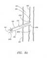
- the sheath 640is retracted proximally such that the distal end region 640b of the sheath 640 is substantially withdrawn from the blood vessel 600, as shown in Fig. E, permitting the apparatus 100 to access the blood vessel wall 620.
- the apparatus 100preferably also is axially rotated such that the first plane defined by the tines 520 of the substantially tubular closure element 500" is substantially parallel with a third plane defined by the blood vessel 600.
- the engagement between the substantially tubular closure element 500" and the blood vessel wall 620 and/or tissue 630can be improved because the tines 520 are configured to engage the blood vessel wall 620 and/or tissue 630 at opposite sides of the opening 610.
- the substantially tubular closure element 500"is disposed on the carrier member 310 such that the first plane defined by the tines 520 is substantially perpendicular to the second plane defined by the switching system 450 and/or the handles 390 (collectively shown in Fig. 5A ), for example, the apparatus 100 can be positioned such that the second plane defined by the switching system 450 and/or the handles 390 is substantially perpendicular to the third plane defined by the blood vessel 600.
- the tube release system 470(shown in Fig. 4D ) is activated to release the tube set 305, which can be advanced distally and received within the lumen 644 of the sheath 64U as illustrated in Fig. 8F .
- the sheath 640can radially expand and/or split in accordance with the predetermined pattern as the tube set 305 advances because the internal cross-section 648b of the sheath 640 is less than or substantially equal to the predetermined cross-section 338b of the cover member 330.
- the carrier member 310, the pusher member 320, the cover member 330, and the support member 340each advance distally and approach the first predetermined position as illustrated in Fig. 8G .
- the tube set 305Upon reaching the first predetermined position, the tube set 305 is disposed substantially adjacent to the outer surface 620a of the blood vessel wall 620 adjacent to the opening 610 such that the blood vessel wall 620 adj acent to the opening 610 is disposed substantially between the expanded distal region 210b of the locator assembly 200 and the tube set 305.
- the cover member 330 and the support member 340each decouple from the carrier member 310 and the pusher member 320 in the manner described in more detail above with reference to Figs. 5A-C when the tube set 305 is in the first predetermined position. Thereby, the cover member 330 and the support member 340 preferably are inhibited from further axial movement and remain substantially stationary as the carrier member 310 and the pusher member 320 each remain coupled and axially slidable.
- the cover member 330 and the support member 340remaining substantially stationary while the carrier member 310 and the pusher member 320 continue distally and approach the second predetermined position.
- the annular cavity 370moves distally relative to the substantialiy-stationary cover member 330 such that the distal end region 330b of the cover member 330 no longer encloses the annular cavity 370.
- the substantially tubular closure element 500"is not completely enclosed by the annular cavity 370 formed by the distal end regions 310b, 320b, and 330b of the carrier member 310, the pusher member 320, and the cover member 330.
- the substantially tubular closure element 500"is advantageously retained on the outer periphery 312b of the carrier member 310 by the distal end region 330b of the cover member 330 as illustrated in Fig. 8H.
- the apparatus 100is configured to provide better tissue penetration.
- the carrier member 310decouples from the pusher member 320 in the manner described in more detail above with reference to Figs. 5A-C . Therefore, the carrier member 310, the cover member 330, and the support member 340 preferably are inhibited from further axial movement and remain substantially stationary; whereas, the pusher member 320 remains axially slidable. As the pusher member 320 continues distally, the distal end region 320b of the pusher member 320 engages the substantially tubular closure element 500" and displaces the substantially tubular closure element 500" from the space 360 as shown in Fig. 8I .
- the pusher member 320directs the substantially tubular closure element 500" over the distally-increasing cross-section of the distal end region 310b of the substantially-stationary carrier member 310 such that the cross-section 530' (shown in Figs. 6F-G ) of the substantially tubular closure element 500" begins to radially expand, preferably in a substantially uniform manner.
- the cross-section 530' of the substantially tubular closure element 500"radially expands beyond natural cross-section 530 (shown in Figs. 6A-B ) of the closure element 500.
- the substantially tubular closure element 500"Upon being directed over the distally-increasing cross-section of the distal end region 310b by the pusher member 320, the substantially tubular closure element 500" is distally deployed as illustrated in Fig. 8J .
- the tines 520can pierce and otherwise engage significant amount of the blood vessel wall 620 and/or tissue 630 adjacent to the opening 610.
- the tines 520can engage significant amount of the blood vessel wall 620 and/or tissue 630 because the cross-section 530' of the substantially tubular closure element 500" is expanded beyond natural cross-section 530 of the closure element 500 during deployment.
- the distal end region 210b of the locator assembly 200also begins to retract proximally and the locator release system 490 (shown in Fig. 4D ) can be activated to transition from the expanded state to the unexpanded state as the substantially tubular closure element 500" is deployed as shown in Fig. 8J .
- the distal end region 210b of the locator assembly 200retracts proximally and transitions from the expanded state to the unexpanded state substantially simultaneously with the deployment of the substantially tubular closure element 500".
- the distal end region 210bmay be configured to draw the blood vessel wall 620 and/or tissue 630 adjacent to the opening 610 proximally and into the channel 540 defined by the substantially tubular closure element 500"
- the tines 520 of the substantially tubular closure element 500"thereby can pierce and otherwise engage the drawn blood vessel wall 620 and/or tissue 630. Since the cross-section 530' of the substantially tubular closure element 500" is expanded beyond natural cross-section 530 of the closure element 500, a significant amount of the blood vessel wall 620 and/or tissue 630 can be drawn into the channel 540 and engaged by the tines 520.
- the substantially tubular closure element 500once deployed, begins to transition from the tubular configuration, returning to the natural, planar configuration with opposing tines 520 and a natural cross-section 530 of the closure element 500.
- the substantially tubular closure element 500"substantially uniformly transitions from the tubular configuration to the natural, planar configuration.
- the tines 520draw the tissue 630 into the channel 540 as the substantially tubular closure element 500" forms the closure element 500.
- the tissue 630is drawn substantially closed and/or sealed as the cross-section 530' of the substantially tubular closure element 500" contracts to return to the natural cross-section 530 of the closure element 500.
- the opening 610 in the blood vessel wall 620can be drawn substantially closed and/or sealed via the closure element 500 as illustrated in Fig. 8L .
- the closure element 500"may be constructed of other materials, that it may comprise alternative shapes, and that it may adopt alternative methods of operation such that the closure element 500" achieves closure of openings in blood vessel walls or other body tissue.
- the closure element 500"is constructed of materials that use a magnetic force to couple a pair of securing elements in order to close an opening in the lumen wall or tissue.
- the closure element 500"may be of a unitary or multi-component construction having a first securing element positionable at a first position adjacent the opening, and a second securing element positionable at a second position adjacent the opening.
- the first and second securing elementsare provided having a magnetic force biasing the first and second securing elements together, thereby closing the opening, or they are provided having a magnetic force biasing both the first and second securing elements toward a third securing element positioned in a manner to cause closure of the opening.
- the magnetic closure element 500"may be provided without tines 520, provided the magnetic force coupling the closure elements is sufficient to close the opening.
- the closure element 500"may be provided with a combination of the magnetic securing elements and tines 520 to provide a combination of coupling forces.
- the distal end region 380b of the housing 380can be configured to couple with an introducer sheath 700 as shown in Fig. 9 .
- the introducer sheath 700has a proximal end region 700a and a distal end region 700b and includes a predetermined length and a predetermined cross-section, both of which can be of any suitable dimension.
- the distal end region 700bis configured to facilitate insertion of the introducer sheath 700 through tissue 630 (shown in Fig. 8A ) and/or into the opening 610 (shown in Fig. 8A ),formed in and/or adjacent to the wall 620 (shown in Fig.
- the distal end region 430bcan have a tapered tip (not shown) for facilitating substantially atraumatic introduction of the introducer sheath 700 through a passage formed in the tissue 630 and/or at least partially into the blood vessel wall 620, which is accessible via the passage.
- the introducer sheath 700has an external cross-section 708b.
- the external cross-section 708b of introducer sheath 700can be of any suitable dimension, and, as desired can be sized such that the introducer sheath 700 can be slidably received and advanced within the lumen 644 (shown in Fig. 8A ) of the sheath 640.
- the introducer sheath 700also forms a lumen 704 that extends along a longitudinal axis of the introducer sheath 700 and substantially between the proximal and distal end regions 700a, 700b.
- the lumen 704can have any suitable length 708a and internal cross-section 708b and is configured to slidably receive the tubular body 210 of the locator assembly 200 (shown in Fig. 4A ) and/or the tube set 305 of the carrier assembly 300 (shown in Fig. 4A ).
- the introducer sheath 700may be configured to radially expand, such as by stretching, to receive the tube set 305.
- the introducer sheath 700can be advantageously configured to split as the tube set 305 is received by, and advances within, the lumen 704 of the introducer sheath 700 in the manner described in more detail above with reference to the sheath 640 (shown in Fig. 8A ).
- the introducer sheath 700can include one or more splits (not shown), such as longitudinal splits, each split being provided in the manner known in the art.
- Each splitis configured to split the introducer sheath 700 in accordance with a predetermined pattern, such as in a spiral pattern. It will be appreciated that, when the internal cross-section 708b of the introducer sheath 700 is greater than the predetermined cross-section 338b of the cover member 330, it may not be necessary for the introducer sheath 700 to be configured to radially expand and/or split.
- the introducer sheath 700can be coupled with the housing 380 via one or more cooperating connectors (not shown) such that the lumen 704 is substantially axially aligned with the tubular body 210 of the locator assembly 200 and/or the tube set 305 of the carrier assembly 300 and, as desired, may be removably and/or substantially permanently coupled with the housing 380.
- a hub assembly 710can be provided on the distal end region of the housing 380b and configured to couple with the proximal end region 700a of the introducer sheath 700.
- the proximal end region 430a of the introducer sheath 700is coupled with, or otherwise provided on, a distal end region 710b of the hub assembly 710, such as via an adhesive, one or more cooperating connectors, and/or a thermo-mechanical joint.
- the hub assembly 710also includes a proximal end region 710a, which provides the one or more mating connectors for coupling the introducer sheath 700 with the housing 380 and forms a lumen (not shown), which extends substantially between the proximal end region 710a and the distal end region 710b.
- the lumen of the hub assembly 710preferably has an internal cross-section or size that is greater than the internal cross-section or size of the lumen 704 of the introducer sheath 700.
- the lumen of the hub assembly 710is configured to communicate with the lumen 704 of the introducer sheath 700.
- the proximal end region 700a of the introducer sheath 700may be flared to facilitate the connection between the introducer sheath 700 and the hub assembly 710.
- the hub assembly 710When properly assembled, the hub assembly 710 preferably is substantially fluid tight such that the one or more devices can be inserted into the lumen 704 of the introducer sheath 700 without fluid passing proximally through the lumen 704.
- the hub assembly 710can be made to be watertight, such as via one or more seals (not shown) and/or valves (not shown) in the manner known in the art.
- the hub assembly 710can include a thrust washer and/or valve, a guide for directing the devices into the lumen 704 of the introducer sheath 700, and/or a seal (collectively not shown).
- the various seals and/or guidescan be coupled with the hub assembly 710 via, for example, one or more spacers and/or end caps (also collectively not shown).
- the hub assembly 710further can include one or more side ports 720.
- the side ports 720can communicate with the lumen of the hub assembly 710 and/or the lumen 704 of the introducer sheath 700.
- At least one of the side ports 720can be configured to be connected with, and to communicate with, tubing (not shown) to, for example, infuse fluids into the lumen 704 and through the introducer sheath 700.
- at least one of the side ports 720can provide a "bleed back" indicator, such as in the manner disclosed in the co-pending application Serial No. 09/680,837 .
- the disclosures of this reference and any others cited thereinare expressly incorporated herein by reference.
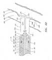
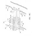
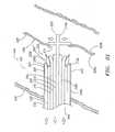
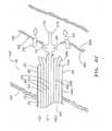
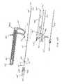
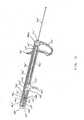
- FIG. 10-15An alternative embodiment of the apparatus is shown in Figs. 10-15 .
- the embodiment of Figs. 10-15has many identical or similar structures that perform identical or similar functions to the embodiment described above and in reference to the preceding Figures.
- components of the apparatusthat are identical or substantially correspond to those previously described will bear the same reference numerals identified above with the addition of the prime ( c ) identifier.
- the locator assembly 200'is substantially similar to the structure described above in reference to Figs. 2A-D , including a flexible or semi-rigid tubular body 210' (such as an elongate rail) with a longitudinal axis 216'.
- the tubular body 210'has a proximal end region 210a' and a distal end region 210b' and includes a predetermined length 218a' and a predetermined outer cross-section 218b', both of which can be of any suitable dimension.
- the distal end region 210b' of the locator assembly 200'preferably includes a substantially rounded, soft, and/or flexible distal end or tip 220' to facilitate atraumatic advancement and/or retraction of the distal end region 210b' into the blood vessel 600.
- a pigtail(not shown) may be provided on the distal end 220' to further aid atraumatic advancement of the distal end region 210b'.
- the distal end region 210b' of the locator assembly 200'further is selectably controllable between an unexpanded state and an expanded state, in the manner described above in relation to Figs. 2A-D .
- the distal end regionis shown in its expanded state, wherein the substantially flexible members 230' of the expansion elements 230' are flexed outward.
- a control member 250'such as a rod, wire, or other elongate member, can be moveably disposed within a lumen (not shown) formed by the tubular body 210' and extending substantially between the proximal end region 210a' and the distal end region 210b'.
- the control member 250'has a proximal end region 250a' that is coupled with a control block 260', and a distal end region that is coupled with the distal end region 210b' of the locator assembly 200', the expansion elements 230', and/or the movable end regions 230c' of the substantially flexible members 230'.
- the control block 260'is preferably of a tubular shape and formed of a metal or rigid plastic, and is adapted to be retained in a control block cavity 265' (see Fig. 10B ) formed on the internal surface of the housing bottom half 380d', to thereby maintain the control block 260' in a substantially fixed position relative to the housing 380'.
- the locator control system 240'can selectively transition the distal end region 210b', the expansion elements 230', and/or the substantially flexible members 230' between the unexpanded and expanded states by moving the tubular body 210' axially relative to the control member 250'.
- a tubular body block 270'having a proximal groove 271'
- the tubular body block 270'is formed of metal, rigid plastic, or other substantially rigid material and is preferably formed integrally with or attached securely to the tubular body 210'.
- the proximal groove 271' and the proximal end of the tubular body block 270'have a shape adapted to cooperate with a pair of tabs 281a'-b' formed on a locator assembly block 280' whereby the tubular body block 270' is maintained in a fixed axial relationship with the locator assembly block 280'. In this way, the tubular body block 270' and tubular body 210' are advanced distally by distal advancement of the locator assembly block 280'.
- a locator assembly spring 290'is located coaxially with and substantially surrounds a portion of the tubular body block 270'.
- the locator assembly spring 290'is located between and contacts the distal side of two of the tabs 281 a formed on the locator assembly block 280', and the proximal side of a locator assembly spring stop 381' formed on the inner surface of the housing bottom half 380d' (see Fig. 10B ).
- the locator assembly spring 290' so locatedprovides a force biasing the locator assembly block 280' in the proximal direction relative to the housing 380'.
- the locator assembly block 280'is preferably formed of metal, plastic, or other rigid material.
- a function of the locator assembly block 280'is to allow the user to apply a force causing distal movement of the tubular body 210' relative to the control member 250' to cause the locator assembly 200' to transition from the unexpanded state to the expanded state.
- the proximal end of the locator assembly block 280'has a slot 281' formed therein, the slot 281' preferably having a size sufficient to accommodate the control block 260' and the control block cavity 265', and to allow the locator assembly block 280' to travel axially relative to the housing 380'.
- the locator assembly block 280'is slidably received and retained within grooves formed in the proximal end of the housing 380', with the proximal end of the locator assembly block extending from the proximal end of the housing.
- the control block 260' and control block cavity 265are located in the slot 281' formed in the proximal end of the locator assembly block 280'.
- the locator release system 490'performs the function of releasing the locator assembly 200', thereby allowing the locator assembly 200' to transition from its expanded state to its unexpanded state.
- the locator release system 490' of the alternative embodiment of the apparatusincludes a locator release rod 491' having a release tab spacer block 492' formed on its proximal end. The locator release rod 491' and release tab spacer block 492' are received and retained in a groove formed on the interior surface of the housing bottom half 380d.
- the release tab spacer block 492'is preferably integrally formed with or attached to the proximal end of the locator release rod 491', and is formed of metal, plastic, or other rigid material. As shown in Fig. 15 , the release tab spacer block 492' has a shape and size adapted to fit between the release tabs 284a-b formed on the locator assembly block 280', thereby biasing the release tabs 284a-b outward and causing the outward facing detents 285a-b to engage a pair of retaining grooves 286a-b formed on the interior of the housing 380'.
- the locator assembly block 280'is held in its axial position against the spring force imparted in the proximal direction by the locator assembly spring 290'.
- the distal end of the locator release rod 491'has an engagement member 493' that, in the preferred embodiment, comprises an inward bend on the distal end of the locator release rod.
- the engagement member 493' on the locator release rod 491'is preferably positioned within the apparatus such that, when the closure clement 500 is delivered, the engagement member 493' is engaged and caused to move axially in the distal direction, thereby disengaging the release tab spacer block 492' from the locator assembly block 280' and causing the locator assembly simultaneously to transition from its expanded state to the unexpanded state.
- the alternative embodiment of the apparatus 100'includes a carrier assembly 300' that is coupled with, and slidable relative to, the locator assembly 200'.
- the carrier assembly 300'is configured to receive and retain the closure element 500 (shown in Figs. 6A-B ), which preferably is disposed substantially within the carrier assembly 300'.
- the locator assembly 200'engages the inner surface 620b (shown in Fig. 8A ) of the blood vessel wall 620 (shown in Fig. 8A )
- the carrier assembly 300'is further configured to position the closure element 500 substantially adjacent to the opening 610 and to deploy the closure element 500, as described elsewhere herein.
- the carrier assembly 300'includes a tube set comprising a carrier member 310', a pusher member 320', a cover member 330', and a support member 340'.
- the carrier member 310', pusher member 320', cover member 330', and support member 340'are preferably provided as a plurality of nested, telescoping members with a common longitudinal axis.
- the carrier member 310'is configured to receive and support the closure element 500, White being disposed on the carrier member 310', the closure element 500 preferably is deformed from the natural, planar configuration to form the substantially tubular closure element 500" (shown in Figs. 6F-G ) as described herein.
- the carrier member 310'includes a proximal end region 310a' and a distal end region 310b'.
- the carrier member 310'can also define a lumen 314' that extends substantially between the proximal end region 310a' and the distal end region 310b' and that is configured to slidably receive at least a portion of the tubular body 210' of the locator assembly 200' and/or the support member 340'.
- the exterior cross-section of the carrier member 310'is substantially uniform, the distal end region 310b' of the carrier member 310' preferably has a cross-section that increases distally, as illustrated in Figs.
- the distal end region 310b'can be formed with a uniform cross-section to deploy the closure element 500 without cross-sectional expansion.
- the pusher member 320'has a proximal end region 320a' and a distal end region 320b' and is coupled with, and slidable relative to, the carrier member 310'.
- the pusher member 320'includes a predetermined length and a predetermined cross-section, both of which can be of any suitable dimension and can be configured to slidably receive the carrier member 310' such that the distal end region 320b' of the pusher member 320' is offset proximally from the distal end region 310b' of the carrier member 310'.
- the predetermined length of the pusher member 320'can be greater than or substantially equal to the predetermined length of the carrier member 310'.
- the predetermined length of the pusher member 320'preferably is less than the predetermined length of the carrier member 310' such that the carrier member 310' and the pusher member 320' at least partially define a space 360' distal to the distal end region 320b' of the pusher member 320' and along the periphery of the carrier member 310'.
- the pusher member 320'preferably is substantially tubular and can define a lumen 324' that extends substantially between the proximal end region 320a' and the distal end region 320b' and that is configured to slidably receive at least a portion of the carrier member 310'.
- the cross-section of the pusher member 320'preferably is substantially uniform, and the distal end region 320b' of the pusher member 320' can comprise one or more longitudinal extensions 325', which extend distally from the pusher member 320' and along the periphery of the carrier member 310'.
- the longitudinal extensions 325'preferably are biased such that the longitudinal extensions 325' extend generally in parallel with the common longitudinal axis of the carrier assembly tube set.
- the longitudinal extensions 325'are sufficiently flexible to expand radially, and yet sufficiently rigid to inhibit buckling, as the distal end region 320b' is directed distally along the carrier member 310' and engage the distally-increasing cross-section of the distal end region 310b' of the carrier member 310' to deploy the substantially tubular closure element 500".
- the cover member 330'is configured to retain the substantially tubular closure element 500" substantially within the carrier assembly 300' prior to deployment. Being coupled with, and slidable relative to, the pusher member 320', the cover member 330' has a proximal end region 330a' and a distal end region 330b' and includes a predetermined length and a predetermined cross-section, both of which can be of any suitable dimension. Preferably being formed as a substantially rigid, semi-rigid, or flexible tubular member, the cover member 330' has an inner periphery and an outer periphery and can define a lumen 334'.
- the lumen 334'extends substantially between the proximal and distal end regions 330a', 330b' of the cover member 330' and can be configured to slidably receive at least a portion of the pusher member 320'.
- the distal end region 330b'is configured to extend over the space 360', thereby defining an annular cavity 370' for receiving and retaining the substantially tubular closure element 500".
- the cross-section of the cover member 330'preferably is substantially uniform, and the distal end region 330b' of the cover member 330' preferably comprises one or more longitudinal extensions 335', which extend distally from the cover member 330' and along an outer periphery of the pusher member 320' (see Fig. 3D ).
- the longitudinal extensions 335'can extend generally in parallel with common longitudinal axis 350', the longitudinal extensions 335' preferably are biased such that the plurality of longitudinal extensions 335' extend substantially radially inwardly as illustrated in Figs. 3A and 3D .
- the longitudinal extensions 335'can at least partially close the lumen 334' substantially adjacent to the distal end region 330b' of the cover member 330'.
- the longitudinal extensions 335'preferably are sufficiently flexible to expand radially to permit the distal end region 310b' of the carrier member 310' to move distally past the cover member 330' to open the annular cavity 370' such that the distal end region 330b' no longer extends over the space 360'.
- the carrier member 310'is at least partially disposed within, and slidable relative to, the lumen 324' of the pusher member 320'.
- the pusher member 320'is at least partially disposed within, and slidable relative to, the lumen 334' of the cover member 330'.
- the tubular body 210' of the locator assembly 200'is at least partially disposed within, and slidable relative to, the lumen 314' of the carrier member 310'.
- the longitudinal axis of the locator assembly 200'preferably is substantially in axial alignment with the common longitudinal axis of the carrier member 310', the pusher member 320', and the cover member 330'.
- the tube set 305preferably also includes a support member 340' as shown in Figs. 10A-B .
- the support member 340'is configured to slidably receive the tubular body 210' of the locator assembly 200' and to provide radial support for the distal end region 210b' of the tubular body 210' when the locator assembly 200' is coupled with the carrier assembly 300'.
- the carrier assembly 300'can advantageously include the support member 340', for example, if the tubular body 210' is not sufficiently rigid or under other circumstances in which support for the tubular body 210' might be desirable.
- the support member 340'also can be configured to inhibit the plurality of longitudinal extensions 335', which extend from the distal end region 330b' of the cover member 330', from expanding prematurely when the closure element 500 is deployed. If the longitudinal extensions 335' were to expand prematurely, they may become hung up on the introducer sheath 640 or other delivery member (in an introducer sheath or delivery member is used), the tissue 630, or the wall 620 of the blood vessel. This may interfere with the proper advancement or other movement of the cover member 330' and the carrier assembly 300'.
- the support member 340'Preferably being formed as a substantially rigid, semi-rigid, or flexible tubular member, the support member 340' includes a proximal end region 340a' and a distal end region 340b'. Having an outer periphery, the support member 340' can define a lumen 344' that extends substantially between the proximal end region 340a' and the distal end region 340b' and that is configured to slidably receive and support at least a portion of the tubular body 210' of the locator assembly 200'.
- the support member 340'in turn, can be at least partially slidably disposed within the lumen 314' of the carrier member 310' such that the tubular body 210' of the locator assembly 200' is coupled with, and slidable relative to, the carrier member 310' in the manner described in more detail above.
- the support member 340'has a predetermined length and a predetermined cross-section, both of which can be of any suitable dimension, and the cross-section preferably is substantially uniform. Although shown and described as being substantially separate for purposes of illustration, it will be appreciated that the carrier member 310', the pusher member 320', the cover member 330', and/or the support member 340' can be provided, in whole or in part, as one or more integrated assemblies.
- the carrier assembly 300'also can include a housing 380', the top half 380c ot which is illustrated in Fig. 10A , and the bottom half 380d of which is shown in Fig. 10B .
- the housing 380'Preferably being formed as an elongate member with a longitudinal axis, the housing 380' has an outer periphery and includes a proximal end region 380a' and a distal end region 380b'.
- the tubular body 210' of the locator assembly 200'is at least partially disposed within, and slidable relative to, the tube set 305 such that the distal end region 210b' of the tubular body 210' extends beyond the distal end regions 310b', 320b', 330b', and/or 340b'.
- the tubular body 210', the carrier member 310', the pusher member 320', the cover member 330', and, if provided, the support member 340'are at least partially disposed within, and slidable relative to, the housing 380', and the respective distal end regions 210b', 310b', 320b', 330b', and 340b' extend from the distal end region 384b' of the housing 380' such that the common longitudinal axis 350' of the tube set 305 is substantially axially aligned with the longitudinal axis 386' of the housing 380', Being configured to slidably retain the respective proximal end regions 210a', 310a', 320a', 330a', and 340a', the housing 380' supports the tube set 305 and can have one or more handles 391', 392' to facilitate use of the apparatus 100'.
- the handles 391', 392'extend substantially radially from the outer periphery of the
- the tubular body 210' of the locator assembly 200'is at least partially disposed within, and slidable relative to, the tube set 305 of the carrier assembly 300' such that the distal end region 210b' of the tubular body 210' extends beyond the distal end regions 310b', 320b', 330b', and/or 340b'.
- the proximal end region 210a' of the tubular body 210' and the proximal end regions 310a', 320a', 330a', and/or 340a' of the tube set 305are at least partially disposed within, and slidable relative to, the housing 380'.
- the switching system of the locator assembly 200' and a switching system 450' of the triggering system 400'preferably are accessible external to the housing 380' as shown in Figs. 11-15 .
- the triggering system 400' of the alternative embodiment of the apparatus 100'can be disposed substantially within the housing 380'.
- the triggering system 400'is configured to control the relative axial movement and/or positioning of the respective distal end regions 310b', 320b', 330b', and 340b' of the tube set 305 and/or the distal end region 210b' of the locator assembly 200'.
- Axial motion of one or more of the carrier member 310', the pusher member 320', the cover member 330', and the support member 340' and/or the tubular body 210'can be attained, for example, by applying an axial force to the switching system 450'.
- the triggering system 400'includes a set of block members - a carrier block 410', a pusher block 420', a cover block 430', and a support block 440' - each of which is formed integrally with or securely attached to its respective member of the carrier assembly 300'.
- the block membersare adapted to selectably couple and decouple the carrier member 310', the pusher member 320', the cover member 330', and the support member 340' relative to one another in order to provide axial movement of those components in a predetermined manner intended to deliver the closure element 500 in the manner described herein.
- the support member 340'can be decoupled from the carrier member 310', the pusher member 320', and the cover member 330' and is thereafter substantially inhibited from further axial movement.
- the carrier member 310', the pusher member 320', and the cover member 330'may be directed distally as the support member 340' remain substantially stationary.
- the carrier member 310' and the cover member 330'can be decoupled from the pusher member 320' and thereafter inhibited from further axial movement.
- the pusher member 320'may be directed distally as the support member 340', carrier member 310', and cover member 330' remain substantially stationary, as described more fully herein.
- the carrier block 410'is disposed on the proximal end region 310a' of the carrier member 310' and includes a trigger extension 405' that extends through a slot in the housing 380' to the exterior of the housing 380' to be accessible to the user.
- the carrier block 410'includes a pair of grooves 413a-b formed on a peripheral surface of the carrier block 410', the grooves 413a-b being adapted to receive and retain a pair of tabs 445a-b formed on a pair of forks 444a-b extending distally from the support block 440', thereby selectably coupling the support block 440' to the carrier block 410'.
- the carrier block 410'also includes a pair of distal tabs 416a-b extending from the distal end of the carrier block 410', and adapted to engage a pair of slots 423a-b formed on the proximal end of the pusher block 420'.
- the carrier block 410'also includes a pair of forks 414a-b extending in the proximal direction from the proximal end of the carrier block, each of the forks having an outward directed tab 415a-b at its proximal end.
- the tabs 415a-bare adapted to selectably engage a pair of slots 387a-b formed on the interior surface of the housing 380' near its proximal end and, when so engaged, to fix the axial position of the carrier block 410' - and, with it, the carrier assembly 300' - relative to the housing 380'.
- the tabs 415a-bare disengaged from the slots in the housing when the locator assembly block 280' is moved axially in the distal direction in the following manner (see Fig. 11B ).
- the interior surfaces of the ramps 283a-b on the locator assembly block forks 282a-bengage the exterior surfaces of the tabs 415a-b and cause the carrier block forks 414a-b to flex inward, releasing the tabs 415a-b from the slots in the housing, thereby freeing the carrier block 410'- and the carrier assembly 300'- to move axially.
- axial movement of the carrier block 410' within the apparatusis inhibited until the locator assembly block 280' is advanced to transition the locator assembly 200' to the expanded condition, simultaneously releasing the tabs 415a-b on the carrier block 410'.
- the pusher block 420'is disposed on the proximal end region 320a' of the pusher member 320'. As described above, the pusher block 420' includes a pair of slots 423a-b formed on its proximal end that are adapted to selectably engage the pair of distal tabs 416a-b extending from the distal end of the carrier block 410'.
- the pusher block 420'also includes a pair of grooves 424a-b formed on its peripheral surface, the grooves 424a-b being adapted to engage a pair of tabs 435a-b formed on a pair of forks 424a-b extending from the proximal side of the cover block 430' to selectably couple the cover block 430' to the pusher block 420'.
- the cover block 430'is disposed on the proximal end region 330a' of the cover member 330'.
- the cover block 430'includes a pair of forks 424a-b extending from the proximal end of the cover block 430', each of the forks having an inward directed tab 435a-b that are adapted to engage the grooves 424a-b on the peripheral surface of the pusher block 420' to selectably couple the cover block 430' to the pusher block 420'.
- the support block 440'is disposed on the proximal end region 340a' of the support member 340'.
- the support blockincludes a pair of forks 444a-b extending from the distal end of the support block 440', each of the forks having an inward directed tab 445 a-b that are adapted to engage the grooves 413a-b formed on the surface of the carrier block 410' to selectably couple the support block 440' to the carrier block 410'.
- the carrier block 410', pusher block 420', cover block 430', and support block 440'are shown in Figs. 11-13 in their fully coupled state, with the support block 440' coupled to the carrier block 410', the pusher block 420' coupled to the carrier block 410', and the cover block 430' coupled to the pusher block 420'.
- the carrier assembly 300'comprises a coaxial set of tubes (as shown, for example, in Fig. 3A ), with the support member 340' slidably retained substantially within the carrier member 310', which is in turn slidably retained substantially within the pusher member 320', which is in turn slidably retained substantially within the cover member 330'.
- the triggering system 400' of the alternative embodiment of the apparatusincludes an energy storing element that is used in the final stage of the closure element 500 delivery process.
- the energy storing elementpreferably a spring such as the pusher spring 425' shown in Figs. 10A-B and 14A-B , is substantially retained in a spring cavity 417' formed in the carrier block 410' and coaxially surrounds a proximal portion 310a' of the carrier member 310'.
- the pusher spring 425'is capable of expanding and contracting, storing potential energy as it is contracted and releasing energy as it expands. In its fully expanded state, the pusher spring 425' has a length that is greater than the length of the spring cavity 417'.
- the cross-sectional dimension of the pusher spring 425'is such that it backs up against and contacts the proximal end of the pusher block 420'.
- the pusher spring 425'is capable of imparting a force biasing the carrier block 410' away from the pusher block 420'.
- the distal end of the carrier block 410'Prior to delivery of the closure element 500, the distal end of the carrier block 410' is in physical contact with the proximal end of the pusher block 420'.
- the pusher spring 425'In this pre-delivery condition, the pusher spring 425' is in a contracted state and is maintained fully within the spring cavity 417' formed in the carrier block 410'.
- a catch member 418'serves the function of maintaining the carrier block 410' and pusher block 420' in the pre-delivery condition against the spring force of the pusher spring 425', the force of which would otherwise force apart the carrier block 410' from the pusher block 420'.
- the catch member 418'is a U-shaped piece of metal, plastic, or other rigid material that engages a first groove 418a formed on the surface of the carrier block 410' and a second groove 418b formed on the surface of the pusher block 420'.
- the pusher block 420'includes a hole 426' extending through a portion thereof, with one end of the hole 426' opening into the groove 418b.
- the hole 426'is adapted to receive a trip pin 427'.
- the trip pin 427'is advanced through the hole 426', where it encounters the catch member 418' that is retained in the groove 418b. Further advancement of the trip pin 427' causes the catch member 418' to become disengaged from the groove 418b, thereby releasing the restraining force on the pusher spring 425'.
- Figs. 11-14The operation of the triggering system 400' of the alternative embodiment of the apparatus 100' is illustrated in Figs. 11-14 with the closure element 500 (shown in Figs. 6A-B ) disposed substantially within the apparatus 100'.
- the apparatushas an initial position in which the locator assembly block 280' is extended proximally and the triggering system 400' is in its most proximal position.
- the locator control system 200'is in its unexpanded state, as shown.
- the locator assembly block 280is depressed distally, as shown in Fig. 12 , thereby transitioning the locator assembly to the expanded state and, simultaneously, releasing the triggering system 400' from the initial position (in the manner described above) such that the triggering system can be advanced distally within the housing 380'.
- the triggering system 400'is then advanced distally within the housing 380', thereby advancing the tube set 305 into position adjacent the blood vessel.
- the support block 440'encounters a support stop (not shown) on the interior surface of the housing bottom half 380d that inhibits the support block 440' from advancing further distally.
- an application of additional distal force to the triggering system 400'causes the support block 440' to decouple from the carrier block 410', as shown in Fig. 13 .
- the tabs 445a-b on the forks 444a-b of the support block 440'disengage from the grooves 413a-b on the carrier block 410'.
- the support block 440'remains in the position shown in Fig. 13 , while the carrier block 410' is able to advance further distally upon application of force to the triggering system 400'.
- the cover block 430'engages a cover stop on the interior surface near the distal end of the housing 380', thereby inhibiting additional distal advancement of the cover block 430'.
- the trigger extension 405'engages the handle 391' on the exterior of the apparatus, thereby inhibiting additional distal advancement of the carrier block 410'.
- the distal end of the tube setcorresponds generally to the state illustrated in Fig. 8G , prior to deployment of the closure element 500.
- the closure element 500is next deployed by releasing the pusher spring 425', which causes the pusher block 420' (and, thus, the pusher member 320') to advance distally, deploying the closure element in the manner described above.
- the pusher spring 425'is released by disengaging the catch member 418' from the groove 418b on the pusher block 420', thereby releasing the pusher spring 425' to force the pusher block 420' - and, thus, the pusher member 320'- distally relative to the carrier block 410'. This action causes the pusher member 320' to deploy the closure element 500, as shown, for example, in Figs. 8H-L.
- the catch member 418'is disengaged from the groove 418b by applying a force to the trigger 401', which, in the deployment position, is aligned with the trip pin 427' retained in the pusher block 420'.
- a trigger spring 402'biases the trigger outward relative to the housing 380'. The user applies an inward directed force to the trigger 401' to counteract the biasing force of the trigger spring 402' and force the trigger 401' against the trip pin 427'.
- the distal advancement of the pusher block 420'also causes the locator release system 490' to activate, thereby transitioning the locator control system 200' from the expanded state to the unexpanded state.
- the pusher block 420'also engages the engagement member 493' of the locator release system 490' and advances the locator release rod 491' distally. This action causes the release tab spacer block 492' to disengage from the release tabs 284a-b on the locator assembly block 230' (see Fig.
- the apparatus 100is preferably brought into contact with the blood vessel 600 by inserting and advancing the distal end of the apparatus through an introducer sheath 640 to the blood vessel location.
- an introducer sheath 640is not necessary, as the apparatus can be used to deploy the closure element 500 without the use of an introducer sheath 640.
- the locator assembly 200, 200' and the carrier assembly 300, 300'may have cross-sectional dimensions that allow them to be received within the introducer sheath 640 either without causing radial expansion or splitting of the sheath, or with causing radial expansion or splitting of the sheath.
- a sheath cutter 701' having a pointed tip 702'may be utilized to initiate a split at the proximal end of the introducer sheath 640.
- the sheath cutter 701'is advantageously placed coaxially over the cover member 330' and is attached to the distal end of the housing 380' (see Figs. 11A-B ), whereby it will initiate a split in the introducer sheath 640.
- Distal advancement of the carrier assembly 300, 300'causes the initial split at the proximal end of the sheath to advance as the carrier assembly 300, 300' advances, as will be understood by those skilled in the art.
Landscapes
- Health & Medical Sciences (AREA)
- Life Sciences & Earth Sciences (AREA)
- Surgery (AREA)
- Molecular Biology (AREA)
- General Health & Medical Sciences (AREA)
- Biomedical Technology (AREA)
- Heart & Thoracic Surgery (AREA)
- Medical Informatics (AREA)
- Nuclear Medicine, Radiotherapy & Molecular Imaging (AREA)
- Animal Behavior & Ethology (AREA)
- Engineering & Computer Science (AREA)
- Public Health (AREA)
- Veterinary Medicine (AREA)
- Cardiology (AREA)
- Surgical Instruments (AREA)
- Clips For Writing Implements (AREA)
- Pens And Brushes (AREA)
Abstract
Description
- The present invention relates generally to apparatus and methods for closing and/or sealing openings through tissue, and more particularly to apparatus and methods for delivering a closure element for closing a puncture in a blood vessel or other body lumen formed during a diagnostic or therapeutic procedure
- Catheterization and interventional procedures, such as angioplasty or stenting, generally are performed by inserting a hollow needle through a patient's skin and tissue into the vascular system. A guide wire may be advanced through the needle and into the patient's blood vessel accessed by the needle. The needle then is removed, enabling an introducer sheath to be advanced over the guide wire into the vessel, e.g., in conjunction with or subsequent to a dilator. A catheter or other device may then be advanced through a lumen of the introducer sheath and over the guide wire into a position for performing a medical procedure. Thus, the introducer sheath may facilitate introducing various devices into the vessel, while minimizing trauma to the vessel wall and/or minimizing blood loss during a procedure.
- Upon completing the procedure, the devices and introducer sheath may be removed, leaving a puncture site in the vessel wall. External pressure may be applied to the puncture site until clotting and wound sealing occur. This procedure, however, may be time consuming and expensive, requiring as much as an hour of a physician's or nurse's time. It is also uncomfortable for the patient, and requires that the patient remain immobilized in the operating room, catheter lab, or holding area. In addition, a risk of hematoma exists from bleeding before hemostasis occurs.
- Various apparatus have been suggested for percutaneously sealing a vascular puncture by occluding the puncture site. For example,
U.S. Patent Nos. 5,192,302 and5,222,974, issued to Kensey et al. , describe the use of a biodegradable plug that may be delivered through an introducer sheath into a puncture site. Another technique has been suggested that involves percutaneously suturing the puncture site, such as that disclosed inU.S. Patent No. 5,304,184, issued to Hathaway et al . - To facilitate positioning devices that are percutaneously inserted into a blood vessel, "bleed back" indicators have been suggested. For example,
U.S. Patent No. 5,676,974, issued to Kensey et al. , discloses a bleed back lumen intended to facilitate positioning of a biodegradable plug within a puncture site. This device, however, requires that an anchor of the plug be positioned within the vessel, and therefore, may increase the nsk of over-advancement of the plug itself into the vessel. - Alternatively,
U.S. Patent No. 5,674,231, issued to Green et al. , discloses a deployable loop that may be advanced through a sheath into a vessel. The loop is intended to resiliently expand to engage the inner wall of the vessel, thereby facilitating holding the sheath in a desired location with respect to the vessel. - Accordingly, apparatus and methods for delivering a device for closing a vascular puncture site or other opening through tissue would be useful.
- The present invention is directed toward an apparatus and method for delivering a closure element through tissue and into an opening formed in, or adjacent to, a wall of a blood vessel or other body lumen of any size.
- The apparatus is configured to receive and retain the closure element such that the closure element is disposed substantially within the apparatus. Thereby, if the apparatus is introduced via an introducer sheath, for example, the closure element can be disposed within, and delivered by way of, a lumen of the introducer sheath. The apparatus also is configured to engage the blood vessel wall adjacent to the opening and to position the closure element substantially adjacent to an outer surface of the blood vessel wall adjacent to the opening.
- When properly positioned, the apparatus can be activated to distally deploy the closure element. During deployment, the apparatus preferably is configured to substantially uniformly expand the closure element beyond a natural cross-section of the closure element such that the closure element, when deployed, is configured to engage significant amount of the
blood vessel wall 620 and/ortissue 630. Engaging the blood vessel wall and/or tissue, the closure element is further configured to return to the natural cross-section. Thereby, the engaged blood vessel wall and/or tissue are drawn substantially closed and/or sealed, such that, for example, hemostasis within the opening is enhanced. - Other aspects and features of the present invention will become apparent from consideration of the following description taken in conjunction with the accompanying drawings.
Fig. 1 provides a general illustration of an apparatus for closing openings formed in blood vessel walls in accordance with the present invention.Fig. 2A illustrates one embodiment of a locator assembly for the apparatus ofFig. 1 .Fig. 2B illustrates one embodiment of a distal end region of the locator assembly otFig. 2A when the distal end region is in an unexpanded state.Fig. 2C illustrates the distal end region of the locator assembly ofFig. 2B when the distal end region is in an expanded state.Fig. 2D illustrates one embodiment of a proximal end region of the locator assembly ofFig. 2A .Fig. 3A illustrates one embodiment of a carrier assembly for the apparatus ofFig. 1 .Fig. 3B illustrates one embodiment of a carrier member for the carrier assembly ofFig. 3A .Fig. 3C illustrates one embodiment of a pusher member for the carrier assembly ofFig. 3A .Fig. 3D illustrates one embodiment of a cover member for the carrier assembly ofFig. 3A .Fig. 3E illustrates one embodiment of a support member for the carrier assembly ofFig. 3A .Fig. 4A illustrates a cross-sectional side view of one embodiment of a triggering system for the carrier assembly ofFig. 3A .Fig. 4B illustrates a first detailed cross-sectional side view of the triggering system ofFig. 4A .Fig. 4C illustrates a detailed view of the triggering system ofFig. 4B .Fig. 4D illustrates a second detailed cross-sectional side view of the triggering system ofFig. 4A .Fig. 5A illustrates the carrier control system ofFigs. 4A-D as the carrier assembly ofFig. 3A moves distally from an initial predetermined position.Fig. 5B illustrates the carrier control system ofFigs. 4A-D as the carrier assembly ofFig. 3A reaches a first predetermined position.Fig. 5C illustrates the carrier control system ofFigs. 4A-D as the carrier assembly ofFig. 3A reaches a second predetermined position.Fig. 6A illustrates a top view of one embodiment of a closure element in a natural, planar configuration and with a natural cross-section for use with the apparatus ofFig. 1 .Fig. 6B illustrates a side view of the closure element ofFig. 6A .Fig. 6C illustrates a top view of the closure element ofFigs. 6A-B after a natural cross-section of the closure element has been reduced.Fig. 6D illustrates a side view of the reduced closure element ofFig. 6C .Fig. 6E illustrates a side view of the reduced closure element ofFigs. 6C-D as the reduced closure element transitions from the natural, planar configuration to a tubular configuration.Fig. 6F illustrates a top view of the closure element ofFigs. 6C-D upon completing the transition from the natural, planar configuration to a substantially tubular configuration.Fig. 6G illustrates a side view of the closure element ofFig. 6F .Fig. 7A illustrates the closure element ofFigs. 6A-G prior to being disposed upon the carrier member ofFig. 3B .Fig. 7B illustrates the closure element ofFigs. 6A-G upon being disposed upon the carrier member ofFig. 3B .Fig. 7C illustrates the closure element ofFigs. 6A-G as the cover member ofFig. 3D receives the carrier member ofFig. 3B .Fig. 7D illustrates the closure element ofFigs. 6A-G being retained substantially within the carrier assembly ofFig. 3A when the carrier member ofFig. 3B is disposed substantially within the cover member ofFig. 3D .Fig. 8A illustrates a sheath that is positioned through tissue and into an opening formed in a wall of a blood vessel.Fig. 8B illustrates the apparatus ofFig. 1 as prepared to be received by the sheath ofFig. 8A .Fig. 8C illustrates a locator assembly of the apparatus ofFig. 8B being advanced distally into the blood vessel.Fig. 8D illustrates a distal end region of the locator assembly ofFig. 8C extending into the blood vessel and being transitioned into an expanded state.Fig. 8E illustrates the distal end region ofFig. 8D being retracted proximally to engage an inner surface of the blood vessel wall.Fig. 8F illustrates a carrier assembly of the apparatus ofFig. 8B being advanced distally into the sheath ofFig. 8A once the distal end region ofFig. 8D has engaged the inner surface of the blood vessel wall.Fig. 8G illustrates relative positions of a tube set of the carrier assembly ofFig. 8F upon reaching a first predetermined position.- Fig. 8H illustrates the relative positions of the tube set of
Fig. 8G upon reaching a second predetermined position. Fig. 8I illustrates a position of a pusher member of the tube set of Fig. 8H moving distally from the second predetermined position and beginning to distally deploy a closure element.Fig. 8J illustrates the closure element ofFig. 8I upon being deployed and engaging tissue adjacent to the opening in the blood vessel wall.Fig. 8K illustrates the closure element ofFig. 8J transitioning from the substantially tubular configuration to the natural, planar configuration while engaging the engaged tissue.Fig. 8L illustrates the closure element ofFig. 8K drawing the engaged tissue substantially closed and/or sealedFig. 9 illustrates one embodiment of an introducer sheath for the apparatus ofFig. 1 .Fig. 10A illustrates an assembly view of the components included in an alternative embodiment of the apparatus for closing openings formed in blood vessel walls.Fig. 10B illustrates an assembly view of the components shown inFig. 10A , showing the reverse view of that shown inFig. 10A .Fig. 11A illustrates the assembled carrier assembly and triggering assembly of the alternative embodiment of the apparatus shown inFig. 10A .Fig. 11B illustrates a close-up view of the proximal end of the apparatus shown inFig. 11A .Fig. 12 illustrates the apparatus ofFig. 11A after advancement of the locator assembly block.Fig. 13A illustrates the apparatus ofFig. 12 after distal advancement of the triggering system and carrier assembly.Fig. 13B illustrates a close-up view of the distal end of the housing and internal components of the apparatus shown inFig. 13A .Fig. 14A illustrates the apparatus ofFig. 13 after further distal advancement of the triggering system and carrier assembly.Fig. 14B illustrates a close-up view of the distal end of the housing and internal components of the apparatus shown inFig. 14A .Fig. 15 illustrates a reverse view of the apparatus ofFigs. 11-14 , showing the locator release system.- It should be noted that the figures are not drawn to scale and that elements of similar structures or functions are generally represented by like reference numerals for illustrative purposes throughout the figures. It also should be noted that the figures are only intended to facilitate the description of the preferred embodiments of the present invention. The figures do not describe every aspect of the present invention and do not limit the scope of the invention.
- Since current apparatuses for sealing openings formed in blood vessel walls can snag tissue adjacent to the openings during positioning and may not provide an adequate seal, an apparatus that is configured to prevent madvertent tissue contact during positioning and to engage a substantial of amount of tissue adjacent to the opening can prove much more desirable and provide a basis for a wide range of medical applications, such as diagnostic and/or therapeutic procedures involving blood vessels or other body lumens of any size. This result can be achieved, according to one embodiment of the present invention, by employing an
apparatus 100 as shown inFig. 1 . - As will be discussed in more detail below, the
apparatus 100 can deliver a closure element 500 (shown inFigs. 6A-B ) through tissue 630 (shown inFig. 8A ) and into an opening 610 (shown inFig. 8A ) formed in and/or adjacent to a wall 620 (shown inFig. 8A ) of a blood vessel 600 (shown inFig. 8A ) or other body lumen. The closure element (or clip) 500 preferably has a generally annular-shape body 510 (shown inFigs. 6A-B ) defining achannel 540 and one or more barbs and/or tines 520 (shown inFigs. 6A-B ) for receiving and engaging theblood vessel wall 620 and/or thetissue 630 around theopening 610. Although theclosure element 500 has a natural shape and size, theclosure element 500 can be deformed into other shapes and sizes, as desired, and is configured to return to the natural shape and size when released. For example, theclosure element 500 can have a natural, planar configuration with opposingtines 520 and anatural cross-section 530 as shown inFigs. 6A-B . Thenatural cross-section 530 of theclosure element 500 can be reduced to form a reduced closure element 500' that has a natural, planar configuration with opposingtines 520 and a reduced cross-section 530' as shown inFigs. 6C-D . By rotating the opposingtines 520 axially as shown inFig. 6E , the reduced closure element 500' can be further deformed to form a substantiallytubular closure element 500" (shown inFig. 6F ) having the reduced cross-section 530' as well as being in a substantially tubular configuration with thetines 520 in an axial configuration. - Being configured to draw the
blood vessel wall 620 and/or thetissue 630 adjacent to theopening 610 substantially closed and/or to enhance hemostasis within theopening 610, theclosure element 500 can be formed from any suitable material, including any biodegradable material, any shape memory alloy, such as alloys of nickel-titanium, or any combination thereof. As desired, theclosure element 500 can include radiopaque markers (not shown) or may be wholly or partially formed from a radiopaque material to facilitate observation of theclosure element 500 using fluoroscopy or other imaging systems. Exemplary embodiments of a closure element are disclosed inU.S. Patent No. 6,197,042 , in co-pending applications Serial Nos.09/546,998 09/610,238 10/081,726 - The
apparatus 100 is configured to receive and retain theclosure element 500 such that theclosure element 500 is disposed substantially within theapparatus 100. Thereby, if theapparatus 100 is introduced via an introducer sheath 640 (shown inFig. 8A ), for example, theclosure element 500 can be disposed within, and delivered by way of, a lumen 644 (shown inFig. 8A ) of theintroducer sheath 640. Theapparatus 100 also is configured to engage theblood vessel wall 620 adjacent to theopening 610. Being disposed substantially within theapparatus 100, theclosure element 500 can deeply penetrate, without inadvertently contacting,tissue 630 adjacent to theopening 610 such that theapparatus 100 can position theclosure element 500 substantially adjacent to an outer surface 620a (shown inFig. 8A ) of theblood vessel wall 620 adjacent to theopening 610. - When properly positioned, the
apparatus 100 can be activated to distally deploy theclosure element 500. Although preferably configured to substantially uniformly expand theclosure element 500 beyond thenatural cross-section 530 of theclosure element 500 during deployment, theapparatus 100, as desired, can deploy theclosure element 500 without expanding theclosure element 500. Theclosure element 500, when deployed, is configured to engage significant amount of theblood vessel wall 620 and/ortissue 630 adjacent to theopening 610. Engaging theblood vessel wall 620 and/ortissue 630, theclosure element 500 is further configured to return to thenatural cross-section 530. Thus, the engagedblood vessel wall 620 and/ortissue 630 are drawn substantially closed and/or sealed, such that, for example, hemostasis within theopening 610 is enhanced. - The
apparatus 100 can be provided as via one or more integrated components and/or discrete components. As shown inFig. 1 , for example, theapparatus 100 can comprise a locator (or obturator)assembly 200 and acarrier assembly 300. For purposes of illustration, thelocator assembly 200 and thecarrier assembly 300 are shown inFig. 1 as comprising substantially separate assemblies. As desired, however, thelocator assembly 200 and thecarrier assembly 300 each can be provided, in whole or in part, as one or more integrated assemblies. - Being configured to extend into the
opening 610, thelocator assembly 200 can selectably engage theinner surface 620b of theblood vessel wall 620 adjacent to theopening 610. Thereby, thelocator assembly 200 is configured to draw theblood vessel wall 620 taut and can maintain the proper position of theapparatus 100 as theblood vessel 600 pulsates. Thelocator assembly 200 can be provided in the manner disclosed in co-pending applications Serial Nos.09/732,835 10/081,723 tubular body 210, such as an elongate rail, with alongitudinal axis 216. As illustrated inFig. 2A , thetubular body 210 has a proximal end region 210a and adistal end region 210b and includes a predetermined length 218a and a predetermined outer cross-section 218b, both of which can be of any suitable dimension. Thedistal end region 210b of thelocator assembly 200 preferably includes a substantially rounded, soft, and/or flexible distal end ortip 220 to facilitate atraumatic advancement and/or retraction of thedistal end region 210b into theblood vessel 600. As desired, a pigtail (not shown) may be provided on thedistal end 220 to further aid atraumatic advancement of thedistal end region 210b. - The
distal end region 210b of thelocator assembly 200 further is selectably controllable between an unexpanded state and an expanded state. In the unexpanded state, thedistal end region 210b has an unexpanded size; whereas, thedistal end region 210b in the expanded state has an expanded size, which is greater than the unexpanded size of thedistal end region 210b in the unexpanded state. Thedistal end region 210b is configured to expand from the unexpanded size to the expanded size and/or to contract from the expanded size to the unexpanded size, and the expansion and contraction of the distal end region 21 0b preferably is substantially uniform about thelongitudinal axis 216. For example, one ormore expansion elements 230 can be provided on thedistal end region 210b and can be configured to expand substantially transversely with respect to alongitudinal axis 216 of thelocator assembly 200. Preferably being substantially equally distributed about anouter periphery 212 of thedistal end region 210b, theexpansion elements 230 may include radiopaque markers (not shown) or may be wholly or partially formed from a radiopaque material to facilitate observation of theexpansion elements 230 and/or thedistal end region 210b using fluoroscopy or other imaging systems. - At least one, and preferably all, of the
expansion elements 230 can comprise a substantially flexible member 230' with a substantially fixedend region 230a', anintermediate region 230b', and amovable end region 230c' as shown inFigs. 2B-C . For each substantially flexible member 230', thefixed end region 230a' is fixedly coupled with thedistal end region 210b; whereas, themovable end region 230c' is movably coupled with thedistal end region 210b and configured to be axially movable relative to thefixed end region 230a'. When eachmovable end region 230c' is axially moved toward the relevantfixed end region 230a', theintermediate regions 230b' buckle and/or expand transversely outwardly, thereby transitioning thedistal end region 210b of thelocator assembly 200 from the unexpanded state to the expanded state. In contrast, thedistal end region 210b transitions from the expanded state to the unexpanded state as each of themovable end regions 230c' are axially moved away from the relevantfixed end region 230a'. Although theexpansion elements 230 are shown as comprising the flexible members 230' inFigs. 2B-C for purposes of illustration, it is understood that theexpansion elements 230 can comprise any type of expansion elements and are not limited to the illustrated embodiments. - Turning to
Fig. 2D , thelocator assembly 200 also can include alocator control system 240 that is coupled with the proximal end region 210a of thelocator assembly 200 and that is configured to selectively control thedistal end region 210b of thelocator assembly 200 between the unexpanded and expanded states. Thelocator control system 240 can selectively control thedistal end region 210b between the unexpanded and expanded states, such as by being activated by a switching system (not shown). For example, acontrol member 250, such as a rod, wire, or other elongate member, can be moveably disposed within a lumen (not shown) formed by thetubular body 210 and extending substantially between the proximal end region 210a and thedistal end region 210b. Thecontrol member 250 has a proximal end region 250a that is coupled with thelocator control system 240, preferably via a control block 260 (shown inFig. 4D ), and a distal end region (not shown) that is coupled with thedistal end region 210b of thelocator assembly 200, theexpansion elements 230, and/or themovable end regions 230c' of the substantially flexible members 230'. Thelocator control system 240 can selectively transition thedistal end region 210b, theexpansion elements 230, and/or the substantially flexible members 230' between the unexpanded and expanded states by moving thecontrol member 250 axially relative to thetubular body 210. - The
locator control system 240 preferably includes alocator release system 490 for maintaining the unexpanded state and/or the expanded state of thedistal end region 210b, theexpansion elements 230, and/or the substantially flexible members 230'. Preferably being configured to maintain the expanded state of thedistal end region 210b, thelocator release system 490 can comprise any type of locking system and can be engaged, for instance, by activating the switching system. For example, once the substantially flexible members 230' have entered the expanded state, thelocator release system 490 can secure thecontrol member 250 to prevent axial movement relative to thetubular body 210, thereby maintaining the substantially flexible members 230' in the expanded state. - In the manner described in more detail below, the
locator control system 240 also can be configured to disengage thelocator release system 490, such that thedistal end region 210b, theexpansion elements 230, and/or the substantially flexible members 230' can transition between the unexpanded and expanded states. Thelocator release system 490 can be disengaged, for example, by activating an emergency release system (not shown). As desired, thelocator control system 240 can further include a biasing system (not shown), such as one or more springs, to bias thedistal end region 210b, theexpansion elements 230, and/or the substantially flexible members 230' to enter and/or maintain the unexpanded state when thelocator release system 490 is disengaged. - Returning to
Fig. 1 , thecarrier assembly 300 is coupled with, and slidable relative to, thelocator assembly 200. Thecarrier assembly 300 is configured to receive and retain the closure element 500 (shown inFigs. 6A-B ), which preferably is disposed substantially within thecarrier assembly 300. When thelocator assembly 200 engages theinner surface 620b (shown inFig. 8A ) of the blood vessel wall 620 (shown inFig. 8A ), thecarrier assembly 300 is further configured to position theclosure element 500 substantially adjacent to the opening 610 (shown inFig. 8A ) and to deploy theclosure element 500. Upon being deployed, theclosure element 500 can maintain the reduced cross-section 530' (shown inFigs. 6C-D ) but preferably can temporarily and substantially uniformly expand beyond the natural cross-section 530 (shown inFigs. 6A-B ) of theclosure element 500. In either case, theclosure element 500, when deployed, can engage significant amount of theblood vessel wall 620 and/ortissue 630 adjacent to theopening 610. Thereafter, theclosure element 500 is configured to return to thenatural cross-section 530, preferably substantially uniformly, such that theblood vessel wall 620 and/ortissue 630 is drawn substantially closed and/or sealed. - Turning to
Figs. 3A-D , thecarrier assembly 300 can include atube set 305, comprising acarrier member 310, apusher member 320, and acover member 330. Thecarrier member 310, thepusher member 320, and thecover member 330 can be provided as a plurality of nested, telescoping members with a commonlongitudinal axis 350 as illustrated inFig. 3A . Thecarrier member 310 is configured to receive and support theclosure element 500. While being disposed on thecarrier member 310, theclosure element 500 preferably is deformed from the natural, planar configuration to form the substantiallytubular closure element 500" (shown inFigs. 6F-G ) as will be discussed in more detail below. Being disposed substantially about, and supported by, anouter periphery 312b of thecarrier member 310, the substantiallytubular closure element 500" can be substantially in axial alignment with thecarrier member 310 with thetines 520 pointed substantially distally. - Preferably being formed as a substantially rigid, semi-rigid, or flexible tubular member, the
carrier member 310 has aproximal end region 310a and adistal end region 310b and includes apredetermined length 318a and apredetermined cross-section 318b, both of which can be of any suitable dimension. Thecarrier member 310 also can define alumen 314 that extends substantially between theproximal end region 310a and thedistal end region 310b and that is configured to slidably receive at least a portion of thetubular body 210 of thelocator assembly 200. Although thecross-section 318b of thecarrier member 310 generally is substantially uniform, thedistal end region 310b of thecarrier member 310 preferably has a cross-section that increases distally, as illustrated inFigs. 3A-B , for substantially uniformly expanding the substantiallytubular closure element 500" beyond thenatural cross-section 530 of theclosure element 500 when the substantiallytubular closure element 500" is deployed. To deploy theclosure element 500 without expanding theclosure element 500, thedistal end region 310b can be formed with a cross-section (not shown) that is substantially uniform. Although shown and described as having the cross-section that increases distally for expanding the substantiallytubular closure element 500", it will be understood that thedistal end region 310b of thecarrier member 310 can be provided with the substantially-uniform cross-section and that the substantiallytubular closure element 500" can be deployed without being expanded. - Being configured to distally deploy the substantially
tubular closure element 500", thepusher member 320 has aproximal end region 320a and adistal end region 320b and is coupled with, and slidable relative to, thecarrier member 310. Thepusher member 320 includes a predetermined length 328a and apredetermined cross-section 328b, both of which can be of any suitable dimension and can be configured to slidably receive thecarrier member 310 such that thedistal end region 320b of thepusher member 320 is offset proximally from thedistal end region 310b of thecarrier member 310. As desired, the predetermined length 328a of thepusher member 320 can be greater than or substantially equal to thepredetermined length 318a of thecarrier member 310. The predetermined length 328a of thepusher member 320 however preferably is less than thepredetermined length 318a of thecarrier member 310 such that thecarrier member 310 and thepusher member 320 at least partially define aspace 360 distal to thedistal end region 320b of thepusher member 320 and along theperiphery 312b of thecarrier member 310. - Being formed from a substantially rigid, semi-rigid, or flexible material, the
pusher member 320 preferably is substantially tubular and can define alumen 324 that extends substantially between theproximal end region 320a and thedistal end region 320b and that is configured to slidably receive at least a portion of thecarrier member 310. Thecross-section 328b of thepusher member 320 preferably is substantially uniform, and thedistal end region 320b of thepusher member 320 can comprise one or morelongitudinal extensions 325, which extend distally from thepusher member 320 and along theperiphery 312b of thecarrier member 310 as shown inFig. 3C . Thelongitudinal extensions 325 preferably are biased such that thelongitudinal extensions 325 extend generally in parallel with commonlongitudinal axis 350. Thelongitudinal extensions 325 are sufficiently flexible to expand radially, and yet sufficiently rigid to inhibit buckling, as thedistal end region 320b is directed distally along thecarrier member 310 and engage the distally-increasing cross-section of thedistal end region 310b of thecarrier member 310 to deploy the substantiallytubular closure element 500". - The
cover member 330 is configured to retain the substantiallytubular closure element 500" substantially within thecarrier assembly 300 prior to deployment. Being coupled with, and slidable relative to, thepusher member 320, thecover member 330 has aproximal end region 330a and adistal end region 330b and includes a predetermined length 338a and apredetermined cross-section 338b, both of which can be of any suitable dimension. Preferably being formed as a substantially rigid, semi-rigid, or flexible tubular member, thecover member 330 has aninner periphery 332a and anouter periphery 332b and can define alumen 334. Thelumen 334 extends substantially between the proximal anddistal end regions cover member 330 and can be configured to slidably receive at least a portion of thepusher member 320. When thecover member 330 is properly positioned within thecarrier assembly 300, thedistal end region 330b is configured to extend over thespace 360, thereby defining anannular cavity 370 for receiving and retaining the substantiallytubular closure element 500". - The
cross-section 338b of thecover member 330 preferably is substantially uniform, and thedistal end region 330b of thecover member 330 preferably comprises one or morelongitudinal extensions 335, which extend distally from thecover member 330 and along anouter periphery 322b of thepusher member 320 as shown inFig. 3D . Although thelongitudinal extensions 335 can extend generally in parallel with commonlongitudinal axis 350, thelongitudinal extensions 335 preferably are biased such that the plurality oflongitudinal extensions 335 extend substantially radially inwardly as illustrated inFigs. 3A and 3D . Thereby, thelongitudinal extensions 335 can at least partially close thelumen 334 substantially adjacent to thedistal end region 330b of thecover member 330. To permit the substantiallytubular closure element 500" to be deployed from theannular cavity 370, thelongitudinal extensions 335 preferably are sufficiently flexible to expand radially to permit thedistal end region 310b of thecarrier member 310 to move distally past thecover member 330 to open theannular cavity 370 such that thedistal end region 330b no longer extends over thespace 360. - If the
carrier assembly 300 is assembled as the plurality of nested, telescoping members as shown inFig. 3A , thecarrier member 310 is at least partially disposed within, and slidable relative to, thelumen 324 of thepusher member 320. Thepusher member 320, in turn, is at least partially disposed within, and slidable relative to, thelumen 334 of thecover member 330. To couple thecarrier assembly 300 with thelocator assembly 200, thetubular body 210 of thelocator assembly 200 is at least partially disposed within, and slidable relative to, thelumen 314 of thecarrier member 310. Thelongitudinal axis 216 of thelocator assembly 200 preferably is substantially in axial alignment with the commonlongitudinal axis 350 of thecarrier member 310, thepusher member 320, and thecover member 330. - It will be appreciated that the tube set 305 preferably also includes a
support member 340 as shown inFigs. 3A and 3E . Thesupport member 340 is configured to slidably receive thetubular body 210 of thelocator assembly 200 and to provide radial support for thedistal end region 210b of thetubular body 210 when thelocator assembly 200 is coupled with thecarrier assembly 300. Thecarrier assembly 300 can advantageously include thesupport member 340, for example, if thetubular body 210 is not sufficiently rigid or under other circumstances in which support for thetubular body 210 might be desirable. It also will be appreciated that thesupport member 340 also can be configured to inhibit the plurality oflongitudinal extensions 335, which extend from thedistal end region 330b of thecover member 330, from expanding prematurely when theclosure element 500 is deployed. - Preferably being formed as a substantially rigid, semi-rigid, or flexible tubular member, the
support member 340 includes a proximal end region 340a and adistal end region 340b. Having anouter periphery 342b, thesupport member 340 can define alumen 344 that extends substantially between the proximal end region 340a and thedistal end region 340b and that is configured to slidably receive and support at least a portion of thetubular body 210 of thelocator assembly 200. Thesupport member 340, in turn, can be at least partially slidably disposed within thelumen 314 of thecarrier member 310 such that thetubular body 210 of thelocator assembly 200 is coupled with, and slidable relative to, thecarrier member 310 in the manner described in more detail above. Thesupport member 340 has a predetermined length 348a and apredetermined cross-section 348b, both of which can be of any suitable dimension, and thecross-section 348b preferably is substantially uniform. Although shown and described as being substantially separate for purposes of illustration, it will be appreciated that thecarrier member 310, thepusher member 320, thecover member 330, and/or thesupport member 340 can be provided, in whole or in part, as one or more integrated assemblies. - The
carrier assembly 300 also can include ahousing 380 as illustrated inFig. 4A . Preferably being formed as an elongate member with alongitudinal axis 386, thehousing 380 has anouter periphery 382b and includes aproximal end region 380a and adistal end region 380b. Thereby, when theapparatus 100 is properly assembled, thetubular body 210 of thelocator assembly 200 at least partially disposed within, and slidable relative to, the tube set 305 such that thedistal end region 210b of thetubular body 210 extends beyond thedistal end regions tubular body 210, thecarrier member 310, thepusher member 320, thecover member 330, and, if provided, thesupport member 340 are at least partially disposed within, and slidable relative to, thehousing 380, and the respectivedistal end regions distal end region 380b of thehousing 380 such that the common longitudinal axis 350 (shown inFig. 3A ) of the tube set 305 is substantially axially aligned with thelongitudinal axis 386 of thehousing 380. Being configured to slidably retain the respectiveproximal end regions housing 380 supports the tube set 305 and can have one ormore handles 390 to facilitate use of theapparatus 100. Thehandles 390 extend substantially radially from theouter periphery 382b of thehousing 380 and can be provided in the manner known in the art. - When the
apparatus 100 is properly assembled, thetubular body 210 of thelocator assembly 200 is at least partially disposed within, and slidable relative to, the tube set 305 of thecarrier assembly 300 such that thedistal end region 210b of thetubular body 210 extends beyond thedistal end regions tubular body 210 and theproximal end regions housing 380. The switching system of thelocator assembly 200 and aswitching system 450 of the triggeringsystem 400 preferably are accessible external to thehousing 380 as shown inFig. 4A . - Turning to
Figs. 4B-D , a triggeringsystem 400 can be disposed substantially within thehousing 380. The triggeringsystem 400 is configured to control the relative axial movement and/or positioning of the respectivedistal end regions distal end region 210b of thelocator assembly 200. Being coupled with theproximal end regions system 400 can control the relative axial movement of thedistal end regions switching system 450. As desired, the triggeringsystem 400 can induce axial motion, such as distal motion, with respect to one or more of thedistal end regions distal end regions carrier member 310, thepusher member 320, thecover member 330, and thesupport member 340 and/or thetubular body 210 can be attained, for example, by applying an axial force to theswitching system 450. To facilitate monitoring of the positioning of thecarrier assembly 300 and/or the substantiallytubular closure element 500", one or more of thedistal end regions - The triggering
system 400 is configured to overcome internal resistance such that the relative axial movement and/or positioning of the respectivedistal end regions distal end region 210b of thelocator assembly 200 are controlled in accordance with a predetermined manner when the triggeringsystem 400 is activated. Thereby, movement and/or positioning of thedistal end regions switching system 450. Stated somewhat differently, a force that is less than the predetermined quantity generally is insufficient to activate the triggeringsystem 400; whereas, when the force increases to a level that is greater than or substantially equal to the predetermined quantity, the triggeringsystem 400 is configured to activate, moving and/or positioning thedistal end regions system 400, once activated, preferably continues to move and/or position thedistal end regions closure element 500 is deployed. - The triggering
system 400, for example, can comprise one or more sets of cooperating detents for coupling the axial motion of thedistal end regions system 400 is activated. The term "detents" refers to any combination of mating elements, such as blocks, tabs, pockets, slots, ramps, locking pins, cantilevered members, support pins, and the like, that may be selectively or automatically engaged and/or disengaged to couple or decouple thecarrier member 310, thepusher member 320, thecover member 330, and thesupport member 340 relative to one another. It will be appreciated that the cooperating detents as illustrated and described below are merely exemplary and not exhaustive. For example, the cooperating detents can include a first set of cooperating blocks and pockets for releasable coupling thesupport member 340, thecarrier member 310, thepusher member 320, and thecover member 330. When thecarrier assembly 300 reaches a first predetermined distal position, thesupport member 340 can be decoupled from thecarrier member 310, thepusher member 320, and thecover member 330 and preferably is substantially inhibited from further axial movement. Thereby, thecarrier member 310, thepusher member 320, and thecover member 330 may continue to be directed distally as thesupport member 340 remains substantially stationary. - As shown in
Figs. 4B-C , the cooperating detents can comprise acarrier block 410, apusher block 420, acover block 430, and asupport block 440, which can be configured to couple and decouple in accordance with the predetermined manner. For example, thecarrier block 410 is disposed on theproximal end region 310a of thecarrier member 310 and includes acarrier pin 412c that extends from thecarrier block 410; whereas, theproximal end region 330a of thecover member 330 and the proximal end region 340a thesupport member 340 are respectively coupled with thecover block 430 and thesupport block 440. A cover pin 432b extends from thecover block 430, and thesupport block 440 has a support pin 442a, which extends from thesupport block 440, The support pin 442a, the cover pin 432b, and thecarrier pin 412c each preferably are formed from a substantially rigid material, such as an alloy of nickel-titanium. - The
pusher block 420 is disposed on theproximal end region 320a of thepusher member 320 and forms asupport slot 422a, acover slot 422b, and acarrier slot 422c. Thesupport slot 422a is configured to receive and releasable engage the support pin 442a by which thesupport member 340 can be coupled with, and decoupled from, thepusher member 320. Thecover member 330 can be coupled with, and decoupled from, thepusher member 320 via thecover slot 422b, which is configured to receive and releasable engage the cover pin 432b. Thecarrier slot 422c is configured to receive and releasable engage thecarrier pin 412c such that thecarrier member 310 can be coupled with, and decoupled from, thepusher member 320. Thecarrier block 410, thepusher block 420, thecover block 430, and thesupport block 440 preferably are respectively disposed substantially on theouter peripheries - The triggering
system 400 also includes one or more stops for engaging thepusher block 420, thecover block 430, and/or thesupport block 440, respectively. As illustrated inFig. 4B , asupport stop 460a, acover stop 460b, and acarrier stop 460c each are formed in thehousing 380 and are configured to receive, and substantially inhibit further movement of, thesupport block 440, thecover block 430, and thecarrier block 410, respectively, in accordance with the predetermined manner. For example, when an axial force is applied to the tube set 305 via theswitching system 450, thecover block 430 moves distally within thehousing 380, and the cover block 430 approaches thecover stop 460b. Upon being received by thecover stop 460b, thecover block 430 is substantially locked in place, substantially preventing any further motion by thecover block 430. - Resisting the axial force, the cover pin 412b provides a static load while the axial force is less than the predetermined quantity of force. As the axial force increases to a level that is greater than or substantially equal to the predetermined quantity, the cover pin 412b can be displaced from the
cover slot 422b, decoupling thecover member 330 from thecarrier member 310, thepusher member 320, and thesupport member 340. Creating the internal resistance to be overcome by the triggeringsystem 400, the static forces provided by thepins 412a, 412b, and 412c is approximately proportional to a composition and cross-section of therespective pins 412a, 412b, and 412c and/or a depth and a slope of therespective slots pins 412a, 412b, and 412c can be configured to provide static loads that are differing and/or substantially uniform. - Turning to
Fig. 4D , the triggeringsystem 400 can further have atube release system 470 for inhibiting inadvertent advancement of the tube set 305. Thetube release system 470 is coupled with atube release member 480, such as a rod, wire, or other elongate member. Thetube release member 480 has a proximal end region 480a that is disposed substantially between thepusher block 420 and the housing 380 (shown inFig. 4A ) and adistal end region 480b that is coupled with thetube release system 470. Preferably, atab 485 is coupled with the proximal end region 480a of thetube release member 480, and a pin (not shown) extends from thepusher block 420 and is disposed substantially between thetab 485 and a groove (not shown) formed in thehousing 380. Thetube release system 470 is configured to release the tube set 305 when thetube release member 480 is moved proximally, freeing thepusher block 420. - A
locator release system 490 for permitting thedistal end region 210b, theexpansion elements 230, and/or the substantially flexible members 230' of thelocator assembly 200 to transition from the expanded state to the unexpanded state can be included with the triggeringsystem 400. Thelocator release system 490 can comprise a rod, wire, or other elongate member and has a proximal end region 490a and adistal end region 490b. The proximal end region 490a of thelocator release system 490 can be coupled with, and configured to activate, the locator control system 240 (shown inFig. 2D ), and thedistal end region 490b extends beyond thepusher block 420. Thereby, when thepusher block 420 is advanced during deployment of theclosure element 500, thecontrol block 260 is disengaged such that thedistal end region 210b, theexpansion elements 230, and/or the substantially flexible members 230' of thelocator assembly 200 to transition from the expanded state to the unexpanded state. - The operation of the triggering
system 400 in accordance with one predetermined manner is illustrated inFigs. 5A-C with the closure element 500 (shown inFigs. 6A-B ) disposed substantially within theapparatus 100. As shown inFig. 5A , thedistal end region 210b of thelocator assembly 200 has been positioned as desired and has transitioned from the unexpanded state to the expanded state. While the locator control system 240 (shown inFig. 2D ) maintains thedistal end region 210b in the expanded state, a distally-directed axial force is applied to the triggeringsystem 400 via theswitching system 450. Once the tube release member 480 (shown inFig. 4D ) has been moved proximally to free thepusher block 420, the tube set 305 is substantially freely slidable within thehousing 380 and responds to the axial force by sliding distally from an initial predetermined position to a first predetermined position. - In the initial predetermined position, the
carrier member 310, thepusher member 320, thecover member 330, and thesupport member 340 are coupled via theslots Fig. 4C ) and thepins Fig. 4C ). Stated somewhat differently, the support pin 442a, the cover pin 432b, and thecarrier pin 412c are respectively disposed within, and engaged by, thesupport slot 422a, thecover slot 422b, and thecarrier slot 422c such that thecarrier block 410, thepusher block 420, thecover block 430, and thesupport block 440 are coupled as illustrated inFig. 4C . Therefore, thecarrier member 310, thepusher member 320, thecover member 330, and thesupport member 340 each slide distally from the initial predetermined position to the first predetermined position in response to the axial force. Fig. 5B illustrates the positions of thecarrier member 310, thepusher member 320, thecover member 330, and thesupport member 340 upon reaching the first predetermined position. In the first predetermined position, thesupport block 440 and thecover block 430 respectively engage thesupport stop 460a and thecover stop 460b. Thereby, thesupport stop 460a receives, and substantially inhibits further movement of, thesupport block 440 and, therefore, thesupport member 340; whereas, thecover stop 460b receives, and substantially inhibits further movement of, thecover block 430 and, therefore, thecover member 330. Although thesupport block 440 and thecover block 430 preferably engage thesupport stop 460a and thecover stop 460b in the first predetermined position, it will be appreciated that thesupport block 440 can engage thesupport stop 460a and thecover block 430 can engage thecover stop 460b in different predetermined positions. In other words, the predetermined manner can comprise any number of predetermined positions, each predetermined position being associated with any number of theblocks relevant stops - To continue distally from the first predetermined position, the
carrier member 310 and thepusher member 320 can be decoupled from thecover member 330 and thesupport member 340 by disengaging the support pin 442a and the cover pin 432b from thesupport slot 422a and thecover slot 422b, respectively. In the manner described in more detail above with reference toFigs. 4B-C , the support pin 442a and the cover pin 432b each resist the axial force. While the axial force is less than the combined static force provided by the support pin 442a and the cover pin 432b, thecarrier member 310 and thepusher member 320 remain coupled with thecover member 330 and thesupport member 340. As the axial force increases to a level that is greater than or substantially equal to the combined static force, the support pin 442a and the cover pin 432b are respectively displaced from thesupport slot 422a and thecover slot 422b, decoupling thecarrier member 310 and thepusher member 320 from thecover member 330 and thesupport member 340. Thereby, thecover member 330 and thesupport member 340 preferably are inhibited from further distal movement and remain substantially stationary; whereas, thecarrier member 310 and thepusher member 320 proceed distally toward a second predetermined position. - The
pusher member 320 and thecarrier member 310 continue distally until the second predetermined position is reached as shown inFig. 5C . In the second predetermined position, thecarrier block 410 engages thecarrier stop 460c. Thereby, thecarrier stop 460c receives, and substantially inhibits further movement of, thecarrier block 410 and, therefore, mecarrier member 310. To continue distally from the second predetermined position, thepusher member 320 can be decoupled from thecarrier member 310 by disengaging thecarrier pin 412c from thecarrier slot 422c. In the manner described in more detail above with reference toFigs. 4B-C , thecarrier pin 412c resists the axial force. While the axial force is less than the static force provided by thecarrier pin 412c, thepusher member 320 remains coupled with thecarrier member 310. - As the axial force increases to a level that is greater than or substantially equal to the static force, the
carrier pin 412c is displaced from thecarrier slot 422c, decoupling thepusher member 320 from thecarrier member 310. Thereby, thecarrier member 310 preferably is inhibited from further distal movement and remains substantially stationary; whereas, thepusher member 320 proceed distally to deploy theclosure element 500 and to activate the locator release system 490 (shown inFig. 2D ) such that thedistal end region 210b, theexpansion elements 230, and/or the substantially flexible members 230' of thelocator assembly 200 transition from the expanded state to the unexpanded state. Preferably, the axial force that is applied to overcome the static force associated with the first predetermined position is sufficient to overcome the static forces associated with the subsequent predetermined positions, to deploy theclosure element 500, and to activate thelocator release system 490 such that the triggeringsystem 400 operates in one substantially-continuous motion. - It will be appreciated that the triggering
system 400 can include an energy storing element (not shown), which can be disposed substantially between thehousing 380 and theblocks closure element 500, and/or activating thelocator release system 490. The energy storing element is configured store the potential energy when the tube set 305 is in the initial predetermine position and to release the potential energy, when activated, such that the tube set 305 travels through the predetermined positions at a substantially constant and continuous rate. For example, the energy storing element can comprise one or more springs (not shown). Each of the springs can be in a compressed state when the tube set 305 is in the initial predetermined position and released from the compressed state when theswitching system 450 of the triggeringsystem 400 is activated. - In use, the
closure element 500 is disposed within thecarrier assembly 300. As shown inFigs. 7A-B , for example, the reduced closure element 500' can be slidably received over the distally-increasingcross-section 318b of thedistal end region 310b of thecarrier member 310 and disposed about theperiphery 312 of thecarrier member 310 adjacent to thespace 360. Since the reduced cross-section 530' of the reduced closure element 500' is less than thecross-section 318b of the distally-increasingcross-section 318b, the reduced closure element 500' must be temporarily radially deformed to be received over thedistal end region 310b. Also, as the reduced closure element 500' is received over thedistal end region 310b, the opposingtines 520 of the reduced closure element 500' engage thedistal end region 310b. The reduced closure element 500' thereby forms the substantiallytubular closure element 500" in the manner described in more detail above with reference toFigs. 6E-G . - After being received over the
distal end region 310b, the substantiallytubular closure element 500" is disposed about thespace 360, and thetines 520 are directed substantially distally as shown inFig. 7B . As desired, one or more of thetines 520 can be disposed proximally of the distally-increasingcross-section 318b of thedistal end region 310b, as illustrated inFig. 7B , and/or can be at least partially disposed upon, and contact, the distally-increasingcross-section 318b of thedistal end region 310b. To improve the engagement between the closure element 500 (shown inFigs. 6A-B ) and theblood vessel wall 620 and/or tissue 630 (collectively shown inFig. 8A ), the substantiallytubular closure element 500" preferably is disposed on thecarrier member 310 such that thetines 520 define a first plane that is substantially perpendicular to a second plane defined by theswitching system 450 and/or the handles 390 (collectively shown inFig. 5A ). - Once disposed about the
space 360, the substantiallytubular closure element 500" can be retained on theouter periphery 312b of thecarrier member 310 whendistal end region 310b of thecarrier member 310 and thedistal end region 320b of thepusher member 320 are slidably received within thelumen 334 of thecover member 330 as illustrated inFigs. 7C-D . When thecover member 330 is properly positioned within thecarrier assembly 300, thedistal end region 330b of thecover member 330 extends over thespace 360 and defines theannular cavity 370 for retaining the substantiallytubular closure element 500". As such, the substantiallytubular closure element 500" is disposed substantially between theouter periphery 312b of thecarrier member 310 and theinner periphery 332a of thecover member 330 such that the substantiallytubular closure element 500" maintains the substantially tubular configuration with thetines 520 being directed substantially distally. As desired, the tube set 305 may radially compress the substantiallytubular closure element 500" such that the substantiallytubular closure element 500" enters and maintains a compressed tubular configuration. Thebody 510 of the substantiallytubular closure element 500" can be disposed distally of thedistal end region 320b of thepusher member 320, as illustrated inFigs. 7C-D , or can engage thedistal end region 320b, as desired. - Turning to
Fig. 8A , asheath 640 may be inserted or otherwise positioned throughskin 650 andtissue 630 and within theblood vessel 600 or other body lumen via theopening 610. Comprising a substantially flexible or semi-rigid tubular member, thesheath 640 has aproximal end region 640a and adistal end region 640b and includes a predetermined length and a predetermined cross-section, both of which can be of any suitable dimension. Thesheath 640 also forms alumen 644 that extends along a longitudinal axis of thesheath 640 and substantially between the proximal anddistal end regions lumen 644 can have any suitableinternal cross-section 648b and is suitable for receiving one or more devices (not shown), such as a catheter, a guide wire, or the like. Thelumen 644 is configured to slidably receive thetubular body 210 of the locator assembly 200 (shown inFig. 4A ) and/or the tube set 305 of the carrier assembly 300 (shown inFig. 4A ). - Since the
internal cross-section 648b of thesheath 640 typically is less than or substantially equal to thepredetermined cross-section 338b of thecover member 330, thesheath 640 may be configured to radially expand, such as by stretching, to receive the tube set 305. Alternatively, or in addition, thesheath 640 can be advantageously configured to split as the tube set 305 is received by, and advances within, thelumen 644 of thesheath 640, thereby permitting theapparatus 100 to access theblood vessel wall 620. To facilitate the splitting, thesheath 640 can include one ormore splits 645, such as longitudinal splits, each split being provided in the manner known in the art. Each split 645 is configured to split thesheath 640 in accordance with a predetermined pattern, such as in a spiral pattern. It will be appreciated that, when theinternal cross-section 648b of thesheath 640 is greater than thepredetermined cross-section 338b of thecover member 330, it may not be necessary for thesheath 640 to be configured to radially expand and/or split. - The
sheath 640 may be advanced over a guide wire or other rail (not shown) that was previously positioned through theopening 610 and into theblood vessel 600 using conventional procedures. Preferably, theblood vessel 600 is a peripheral blood vessel, such as a femoral or carotid artery, although other body lumens may be accessed using thesheath 640 as will be appreciated by those skilled in the art. Theopening 610, and consequently thesheath 640, may be oriented with respect to theblood vessel 600 such as to facilitate the introduction of devices through thelumen 644 of thesheath 640 and into theblood vessel 600 with minimal risk of damage to theblood vessel 600. One or more devices (not shown), such as a catheter, a guide wire, or the like, may be inserted through thesheath 640 and advanced to a preselected location within the patient's body. For example, the devices may be used to perform a therapeutic or diagnostic procedure, such as angioplasty, atherectomy, stent implantation, and the like, within the patent's vasculature. - Alter the procedure is complete, the devices are removed from me
seam 640, ana theapparatus 100 is prepared to be received by thelumen 644 of thesheath 640 as shown inFig. 8B . Being in the unexpanded state, thedistal end region 210b of thetubular body 210 of thelocator assembly 200 is slidably received by thelumen 644 and atraumatically advanced distally into theblood vessel 600 as illustrated inFigs. 8B-C . Once thedistal end region 210b of thetubular body 210 extends into theblood vessel 600, thedistal end region 210b can transition from the unexpanded state to the expanded state as shown inFig. 8D by activating the switching system of thelocator assembly 200. - Turning to
Fig. 8E , theapparatus 100 and thesheath 640 then are retracted proximally until thedistal end region 210b is substantially adjacent to aninner surface 620b of theblood vessel wall 620. Thedistal end region 210b thereby draws theblood vessel wall 620 taut and maintains the proper position of theapparatus 100 as theblood vessel 600 pulsates. Since the expanded cross-section of thedistal end region 210b is greater than or substantially equal to the cross-section of theopening 610 and/or the cross-section of thelumen 644, thedistal end region 210b remains in theblood vessel 600 and engages theinner surface 620b of theblood vessel wall 620. Thedistal end region 210b can frictionally engage theinner surface 620b of theblood vessel wall 620, thereby securing theapparatus 100 to theblood vessel 600. Thesheath 640 is retracted proximally such that thedistal end region 640b of thesheath 640 is substantially withdrawn from theblood vessel 600, as shown in Fig. E, permitting theapparatus 100 to access theblood vessel wall 620. - As the
apparatus 100 is being retracted, theapparatus 100 preferably also is axially rotated such that the first plane defined by thetines 520 of the substantiallytubular closure element 500" is substantially parallel with a third plane defined by theblood vessel 600. Thereby, the engagement between the substantiallytubular closure element 500" and theblood vessel wall 620 and/ortissue 630 can be improved because thetines 520 are configured to engage theblood vessel wall 620 and/ortissue 630 at opposite sides of theopening 610. If the substantiallytubular closure element 500" is disposed on thecarrier member 310 such that the first plane defined by thetines 520 is substantially perpendicular to the second plane defined by theswitching system 450 and/or the handles 390 (collectively shown inFig. 5A ), for example, theapparatus 100 can be positioned such that the second plane defined by theswitching system 450 and/or thehandles 390 is substantially perpendicular to the third plane defined by theblood vessel 600. - Once the
distal end region 210b of thelocator assembly 200 engages theinner surface 620b of theblood vessel wall 620, the tube release system 470 (shown inFig. 4D ) is activated to release the tube set 305, which can be advanced distally and received within thelumen 644 of the sheath 64U as illustrated inFig. 8F . in the manner described in more detail above with reference toFig. 8A , thesheath 640 can radially expand and/or split in accordance with the predetermined pattern as the tube set 305 advances because theinternal cross-section 648b of thesheath 640 is less than or substantially equal to thepredetermined cross-section 338b of thecover member 330. Being coupled, thecarrier member 310, thepusher member 320, thecover member 330, and thesupport member 340 each advance distally and approach the first predetermined position as illustrated inFig. 8G . - Upon reaching the first predetermined position, the tube set 305 is disposed substantially adjacent to the outer surface 620a of the
blood vessel wall 620 adjacent to theopening 610 such that theblood vessel wall 620 adj acent to theopening 610 is disposed substantially between the expandeddistal region 210b of thelocator assembly 200 and the tube set 305. Thecover member 330 and thesupport member 340 each decouple from thecarrier member 310 and thepusher member 320 in the manner described in more detail above with reference toFigs. 5A-C when the tube set 305 is in the first predetermined position. Thereby, thecover member 330 and thesupport member 340 preferably are inhibited from further axial movement and remain substantially stationary as thecarrier member 310 and thepusher member 320 each remain coupled and axially slidable. - As shown in Fig. 8H, the
cover member 330 and thesupport member 340 remaining substantially stationary while thecarrier member 310 and thepusher member 320 continue distally and approach the second predetermined position. As thecarrier member 310 and thepusher member 320 distally advance toward the second predetermined position, theannular cavity 370 moves distally relative to the substantialiy-stationary cover member 330 such that thedistal end region 330b of thecover member 330 no longer encloses theannular cavity 370. Thereby, the substantiallytubular closure element 500" is not completely enclosed by theannular cavity 370 formed by thedistal end regions carrier member 310, thepusher member 320, and thecover member 330. - Although not completely enclosed by the
annular cavity 370, the substantiallytubular closure element 500" is advantageously retained on theouter periphery 312b of thecarrier member 310 by thedistal end region 330b of thecover member 330 as illustrated in Fig. 8H. For example, by retaining the substantiallytubular closure element 500" between thedistal end region 330b of thecover member 330 and thedistal end region 310b thecarrier member 310, theapparatus 100 is configured to provide better tissue penetration. The timing between the deployment of the substantiallytubular closure element 500" by the tube set 305 and the retraction and transition to the unexpanded state by thelocator assembly 200 likewise is facilitated because the substantiallytubular closure element 500" is retained between thedistal end region 330b and thedistal end region 310b. Further, thecarrier member 310 ana thecover member 330 operate to maintain the substantiallytubular closure element 500" in the tubular configuration. - When the tube set 305 is in the second predetermined position, the
carrier member 310 decouples from thepusher member 320 in the manner described in more detail above with reference toFigs. 5A-C . Therefore, thecarrier member 310, thecover member 330, and thesupport member 340 preferably are inhibited from further axial movement and remain substantially stationary; whereas, thepusher member 320 remains axially slidable. As thepusher member 320 continues distally, thedistal end region 320b of thepusher member 320 engages the substantiallytubular closure element 500" and displaces the substantiallytubular closure element 500" from thespace 360 as shown inFig. 8I . Since thespace 360 is substantially radially exposed, thepusher member 320 directs the substantiallytubular closure element 500" over the distally-increasing cross-section of thedistal end region 310b of the substantially-stationary carrier member 310 such that the cross-section 530' (shown inFigs. 6F-G ) of the substantiallytubular closure element 500" begins to radially expand, preferably in a substantially uniform manner. As the substantiallytubular closure element 500" traverses the distally-increasing cross-section of thedistal end region 310b, the cross-section 530' of the substantiallytubular closure element 500" radially expands beyond natural cross-section 530 (shown inFigs. 6A-B ) of theclosure element 500. - Upon being directed over the distally-increasing cross-section of the
distal end region 310b by thepusher member 320, the substantiallytubular closure element 500" is distally deployed as illustrated inFig. 8J . When the substantiallytubular closure element 500" is deployed, thetines 520 can pierce and otherwise engage significant amount of theblood vessel wall 620 and/ortissue 630 adjacent to theopening 610. For example, thetines 520 can engage significant amount of theblood vessel wall 620 and/ortissue 630 because the cross-section 530' of the substantiallytubular closure element 500" is expanded beyondnatural cross-section 530 of theclosure element 500 during deployment. - The
distal end region 210b of thelocator assembly 200 also begins to retract proximally and the locator release system 490 (shown inFig. 4D ) can be activated to transition from the expanded state to the unexpanded state as the substantiallytubular closure element 500" is deployed as shown inFig. 8J . Preferably, thedistal end region 210b of thelocator assembly 200 retracts proximally and transitions from the expanded state to the unexpanded state substantially simultaneously with the deployment of the substantiallytubular closure element 500". As desired, thedistal end region 210b may be configured to draw theblood vessel wall 620 and/ortissue 630 adjacent to theopening 610 proximally and into thechannel 540 defined by the substantiallytubular closure element 500" Thetines 520 of the substantiallytubular closure element 500" thereby can pierce and otherwise engage the drawnblood vessel wall 620 and/ortissue 630. Since the cross-section 530' of the substantiallytubular closure element 500" is expanded beyondnatural cross-section 530 of theclosure element 500, a significant amount of theblood vessel wall 620 and/ortissue 630 can be drawn into thechannel 540 and engaged by thetines 520. - Turning to
Fig. 8K , the substantiallytubular closure element 500", once deployed, begins to transition from the tubular configuration, returning to the natural, planar configuration with opposingtines 520 and anatural cross-section 530 of theclosure element 500. Preferably, the substantiallytubular closure element 500" substantially uniformly transitions from the tubular configuration to the natural, planar configuration. Rotating axially inwardly to form the opposingtines 520 of theclosure element 500, thetines 520 draw thetissue 630 into thechannel 540 as the substantiallytubular closure element 500" forms theclosure element 500. Also, thetissue 630 is drawn substantially closed and/or sealed as the cross-section 530' of the substantiallytubular closure element 500" contracts to return to thenatural cross-section 530 of theclosure element 500. Thereby, theopening 610 in theblood vessel wall 620 can be drawn substantially closed and/or sealed via theclosure element 500 as illustrated inFig. 8L . - It will be appreciated that the
closure element 500" may be constructed of other materials, that it may comprise alternative shapes, and that it may adopt alternative methods of operation such that theclosure element 500" achieves closure of openings in blood vessel walls or other body tissue. In an additional non-limiting example, theclosure element 500" is constructed of materials that use a magnetic force to couple a pair of securing elements in order to close an opening in the lumen wall or tissue. In this alternative embodiment, theclosure element 500" may be of a unitary or multi-component construction having a first securing element positionable at a first position adjacent the opening, and a second securing element positionable at a second position adjacent the opening. The first and second securing elements are provided having a magnetic force biasing the first and second securing elements together, thereby closing the opening, or they are provided having a magnetic force biasing both the first and second securing elements toward a third securing element positioned in a manner to cause closure of the opening. Themagnetic closure element 500" may be provided withouttines 520, provided the magnetic force coupling the closure elements is sufficient to close the opening. Alternatively, theclosure element 500" may be provided with a combination of the magnetic securing elements andtines 520 to provide a combination of coupling forces. Those skilled in the art will recognize that other and further materials, methods, and combinations maybe utilized to construct theclosure element 500" to achieve the objectives described and implied herein. - It will be appreciated that the
distal end region 380b of thehousing 380 can be configured to couple with anintroducer sheath 700 as shown inFig. 9 . Comprising a substantially flexible or semi-rigid tubular member, theintroducer sheath 700 has a proximal end region 700a and adistal end region 700b and includes a predetermined length and a predetermined cross-section, both of which can be of any suitable dimension. Thedistal end region 700b is configured to facilitate insertion of theintroducer sheath 700 through tissue 630 (shown inFig. 8A ) and/or into the opening 610 (shown inFig. 8A ),formed in and/or adjacent to the wall 620 (shown inFig. 8A ) of the blood vessel 600 (shown inFig. 8A ) or other body lumen. For example, the distal end region 430b can have a tapered tip (not shown) for facilitating substantially atraumatic introduction of theintroducer sheath 700 through a passage formed in thetissue 630 and/or at least partially into theblood vessel wall 620, which is accessible via the passage. Theintroducer sheath 700 has anexternal cross-section 708b. Theexternal cross-section 708b ofintroducer sheath 700 can be of any suitable dimension, and, as desired can be sized such that theintroducer sheath 700 can be slidably received and advanced within the lumen 644 (shown inFig. 8A ) of thesheath 640. - The
introducer sheath 700 also forms alumen 704 that extends along a longitudinal axis of theintroducer sheath 700 and substantially between the proximal anddistal end regions 700a, 700b. Thelumen 704 can have anysuitable length 708a andinternal cross-section 708b and is configured to slidably receive thetubular body 210 of the locator assembly 200 (shown inFig. 4A ) and/or the tube set 305 of the carrier assembly 300 (shown inFig. 4A ). Since theinternal cross-section 708b of theintroducer sheath 700 typically is less than or substantially equal to thepredetermined cross-section 338b of thecover member 330, theintroducer sheath 700 may be configured to radially expand, such as by stretching, to receive the tube set 305. Alternatively, or in addition, theintroducer sheath 700 can be advantageously configured to split as the tube set 305 is received by, and advances within, thelumen 704 of theintroducer sheath 700 in the manner described in more detail above with reference to the sheath 640 (shown inFig. 8A ). To facilitate the splitting, theintroducer sheath 700 can include one or more splits (not shown), such as longitudinal splits, each split being provided in the manner known in the art. Each split is configured to split theintroducer sheath 700 in accordance with a predetermined pattern, such as in a spiral pattern. It will be appreciated that, when theinternal cross-section 708b of theintroducer sheath 700 is greater than thepredetermined cross-section 338b of thecover member 330, it may not be necessary for theintroducer sheath 700 to be configured to radially expand and/or split. - The
introducer sheath 700 can be coupled with thehousing 380 via one or more cooperating connectors (not shown) such that thelumen 704 is substantially axially aligned with thetubular body 210 of thelocator assembly 200 and/or the tube set 305 of thecarrier assembly 300 and, as desired, may be removably and/or substantially permanently coupled with thehousing 380. For example, ahub assembly 710 can be provided on the distal end region of thehousing 380b and configured to couple with the proximal end region 700a of theintroducer sheath 700. The proximal end region 430a of theintroducer sheath 700 is coupled with, or otherwise provided on, adistal end region 710b of thehub assembly 710, such as via an adhesive, one or more cooperating connectors, and/or a thermo-mechanical joint. - The
hub assembly 710 also includes a proximal end region 710a, which provides the one or more mating connectors for coupling theintroducer sheath 700 with thehousing 380 and forms a lumen (not shown), which extends substantially between the proximal end region 710a and thedistal end region 710b. The lumen of thehub assembly 710 preferably has an internal cross-section or size that is greater than the internal cross-section or size of thelumen 704 of theintroducer sheath 700. When the proximal end region 710a of thelumen 704 is properly connected with thehub assembly 710, the lumen of thehub assembly 710 is configured to communicate with thelumen 704 of theintroducer sheath 700. As desired, the proximal end region 700a of theintroducer sheath 700 may be flared to facilitate the connection between theintroducer sheath 700 and thehub assembly 710. - When properly assembled, the
hub assembly 710 preferably is substantially fluid tight such that the one or more devices can be inserted into thelumen 704 of theintroducer sheath 700 without fluid passing proximally through thelumen 704. Thehub assembly 710 can be made to be watertight, such as via one or more seals (not shown) and/or valves (not shown) in the manner known in the art. For example, thehub assembly 710 can include a thrust washer and/or valve, a guide for directing the devices into thelumen 704 of theintroducer sheath 700, and/or a seal (collectively not shown). The various seals and/or guides can be coupled with thehub assembly 710 via, for example, one or more spacers and/or end caps (also collectively not shown). - As desired, the
hub assembly 710 further can include one ormore side ports 720. Theside ports 720 can communicate with the lumen of thehub assembly 710 and/or thelumen 704 of theintroducer sheath 700. At least one of theside ports 720 can be configured to be connected with, and to communicate with, tubing (not shown) to, for example, infuse fluids into thelumen 704 and through theintroducer sheath 700. Alternatively, or in addition, at least one of theside ports 720 can provide a "bleed back" indicator, such as in the manner disclosed in the co-pending application Serial No.09/680,837 - An alternative embodiment of the apparatus is shown in
Figs. 10-15 . The embodiment ofFigs. 10-15 has many identical or similar structures that perform identical or similar functions to the embodiment described above and in reference to the preceding Figures. In the description of the alternative embodiment below, and inFigs. 10-15 , components of the apparatus that are identical or substantially correspond to those previously described will bear the same reference numerals identified above with the addition of the prime (c) identifier. - Turning to
Figs. 10 and11 , the locator assembly 200' is substantially similar to the structure described above in reference toFigs. 2A-D , including a flexible or semi-rigid tubular body 210' (such as an elongate rail) with a longitudinal axis 216'. The tubular body 210' has a proximal end region 210a' and adistal end region 210b' and includes a predetermined length 218a' and a predetermined outer cross-section 218b', both of which can be of any suitable dimension. Thedistal end region 210b' of the locator assembly 200' preferably includes a substantially rounded, soft, and/or flexible distal end or tip 220' to facilitate atraumatic advancement and/or retraction of thedistal end region 210b' into theblood vessel 600. As desired, a pigtail (not shown) may be provided on the distal end 220' to further aid atraumatic advancement of thedistal end region 210b'. - The
distal end region 210b' of the locator assembly 200' further is selectably controllable between an unexpanded state and an expanded state, in the manner described above in relation toFigs. 2A-D . In the alternative embodiment shown inFigs. 10A-B , the distal end region is shown in its expanded state, wherein the substantially flexible members 230' of the expansion elements 230' are flexed outward. - A control member 250', such as a rod, wire, or other elongate member, can be moveably disposed within a lumen (not shown) formed by the tubular body 210' and extending substantially between the proximal end region 210a' and the
distal end region 210b'. The control member 250' has a proximal end region 250a' that is coupled with a control block 260', and a distal end region that is coupled with thedistal end region 210b' of the locator assembly 200', the expansion elements 230', and/or themovable end regions 230c' of the substantially flexible members 230'. The control block 260' is preferably of a tubular shape and formed of a metal or rigid plastic, and is adapted to be retained in a control block cavity 265' (seeFig. 10B ) formed on the internal surface of thehousing bottom half 380d', to thereby maintain the control block 260' in a substantially fixed position relative to the housing 380'. The locator control system 240' can selectively transition thedistal end region 210b', the expansion elements 230', and/or the substantially flexible members 230' between the unexpanded and expanded states by moving the tubular body 210' axially relative to the control member 250'. - Formed on the proximal end 210a' of the tubular body 210' is a tubular body block 270' having a proximal groove 271', The tubular body block 270' is formed of metal, rigid plastic, or other substantially rigid material and is preferably formed integrally with or attached securely to the tubular body 210'. The proximal groove 271' and the proximal end of the tubular body block 270' have a shape adapted to cooperate with a pair of
tabs 281a'-b' formed on a locator assembly block 280' whereby the tubular body block 270' is maintained in a fixed axial relationship with the locator assembly block 280'. In this way, the tubular body block 270' and tubular body 210' are advanced distally by distal advancement of the locator assembly block 280'. - A locator assembly spring 290' is located coaxially with and substantially surrounds a portion of the tubular body block 270'. The locator assembly spring 290' is located between and contacts the distal side of two of the
tabs 281 a formed on the locator assembly block 280', and the proximal side of a locator assembly spring stop 381' formed on the inner surface of thehousing bottom half 380d' (seeFig. 10B ). The locator assembly spring 290' so located provides a force biasing the locator assembly block 280' in the proximal direction relative to the housing 380'. - The locator assembly block 280' is preferably formed of metal, plastic, or other rigid material. A function of the locator assembly block 280' is to allow the user to apply a force causing distal movement of the tubular body 210' relative to the control member 250' to cause the locator assembly 200' to transition from the unexpanded state to the expanded state. The proximal end of the locator assembly block 280' has a slot 281' formed therein, the slot 281' preferably having a size sufficient to accommodate the control block 260' and the control block cavity 265', and to allow the locator assembly block 280' to travel axially relative to the housing 380'. The distal end of the locator assembly block 280' has a pair of distally extending
forks 282a-b, with each of theforks 282a-b having aramp 283a-b on its inward facing surface. Finally, the locator assembly block 280' has a pair of distally extending release tabs 284a-b, with each of the release tabs 284a-b having adetent 285a-b. - As shown in
Figs. 11A-B , the locator assembly block 280' is slidably received and retained within grooves formed in the proximal end of the housing 380', with the proximal end of the locator assembly block extending from the proximal end of the housing. The control block 260' and controlblock cavity 265 are located in the slot 281' formed in the proximal end of the locator assembly block 280'. - The locator release system 490' performs the function of releasing the locator assembly 200', thereby allowing the locator assembly 200' to transition from its expanded state to its unexpanded state. Turning to
Figs. 10A-B andFig. 15 , the locator release system 490' of the alternative embodiment of the apparatus includes a locator release rod 491' having a release tab spacer block 492' formed on its proximal end. The locator release rod 491' and release tab spacer block 492' are received and retained in a groove formed on the interior surface of thehousing bottom half 380d. The release tab spacer block 492' is preferably integrally formed with or attached to the proximal end of the locator release rod 491', and is formed of metal, plastic, or other rigid material. As shown inFig. 15 , the release tab spacer block 492' has a shape and size adapted to fit between the release tabs 284a-b formed on the locator assembly block 280', thereby biasing the release tabs 284a-b outward and causing theoutward facing detents 285a-b to engage a pair of retaining grooves 286a-b formed on the interior of the housing 380'. As long as thedetents 285a-b are thus engaged with the retaining grooves 286a-b of the housing 380', the locator assembly block 280' is held in its axial position against the spring force imparted in the proximal direction by the locator assembly spring 290'. The distal end of the locator release rod 491' has an engagement member 493' that, in the preferred embodiment, comprises an inward bend on the distal end of the locator release rod. As described more fully below, the engagement member 493' on the locator release rod 491' is preferably positioned within the apparatus such that, when theclosure clement 500 is delivered, the engagement member 493' is engaged and caused to move axially in the distal direction, thereby disengaging the release tab spacer block 492' from the locator assembly block 280' and causing the locator assembly simultaneously to transition from its expanded state to the unexpanded state. - The alternative embodiment of the apparatus 100' includes a carrier assembly 300' that is coupled with, and slidable relative to, the locator assembly 200'. The carrier assembly 300' is configured to receive and retain the closure element 500 (shown in
Figs. 6A-B ), which preferably is disposed substantially within the carrier assembly 300'. When the locator assembly 200' engages theinner surface 620b (shown inFig. 8A ) of the blood vessel wall 620 (shown inFig. 8A ), the carrier assembly 300' is further configured to position theclosure element 500 substantially adjacent to theopening 610 and to deploy theclosure element 500, as described elsewhere herein. - Turning to
Figs. 10A-B , the carrier assembly 300' includes a tube set comprising a carrier member 310', a pusher member 320', a cover member 330', and a support member 340'. The carrier member 310', pusher member 320', cover member 330', and support member 340' are preferably provided as a plurality of nested, telescoping members with a common longitudinal axis. The carrier member 310' is configured to receive and support theclosure element 500, White being disposed on the carrier member 310', theclosure element 500 preferably is deformed from the natural, planar configuration to form the substantiallytubular closure element 500" (shown inFigs. 6F-G ) as described herein. - The carrier member 310' includes a
proximal end region 310a' and adistal end region 310b'. The carrier member 310' can also define a lumen 314' that extends substantially between theproximal end region 310a' and thedistal end region 310b' and that is configured to slidably receive at least a portion of the tubular body 210' of the locator assembly 200' and/or the support member 340'. Although the exterior cross-section of the carrier member 310' is substantially uniform, thedistal end region 310b' of the carrier member 310' preferably has a cross-section that increases distally, as illustrated inFigs. 10A-B , for substantially uniformly expanding the substantiallytubular closure element 500" beyond thenatural cross-section 530 of theclosure element 500 when the substantiallytubular closure element 500" is deployed. Alternatively, the distal end region 310b'can be formed with a uniform cross-section to deploy theclosure element 500 without cross-sectional expansion. - The pusher member 320' has a
proximal end region 320a' and adistal end region 320b' and is coupled with, and slidable relative to, the carrier member 310'. The pusher member 320' includes a predetermined length and a predetermined cross-section, both of which can be of any suitable dimension and can be configured to slidably receive the carrier member 310' such that thedistal end region 320b' of the pusher member 320' is offset proximally from thedistal end region 310b' of the carrier member 310'. As desired, the predetermined length of the pusher member 320' can be greater than or substantially equal to the predetermined length of the carrier member 310'. The predetermined length of the pusher member 320' preferably is less than the predetermined length of the carrier member 310' such that the carrier member 310' and the pusher member 320' at least partially define a space 360' distal to thedistal end region 320b' of the pusher member 320' and along the periphery of the carrier member 310'. - The pusher member 320' preferably is substantially tubular and can define a lumen 324' that extends substantially between the
proximal end region 320a' and thedistal end region 320b' and that is configured to slidably receive at least a portion of the carrier member 310'. The cross-section of the pusher member 320' preferably is substantially uniform, and thedistal end region 320b' of the pusher member 320' can comprise one or more longitudinal extensions 325', which extend distally from the pusher member 320' and along the periphery of the carrier member 310'. The longitudinal extensions 325' preferably are biased such that the longitudinal extensions 325' extend generally in parallel with the common longitudinal axis of the carrier assembly tube set. The longitudinal extensions 325' are sufficiently flexible to expand radially, and yet sufficiently rigid to inhibit buckling, as thedistal end region 320b' is directed distally along the carrier member 310' and engage the distally-increasing cross-section of thedistal end region 310b' of the carrier member 310' to deploy the substantiallytubular closure element 500". - The cover member 330' is configured to retain the substantially
tubular closure element 500" substantially within the carrier assembly 300' prior to deployment. Being coupled with, and slidable relative to, the pusher member 320', the cover member 330' has aproximal end region 330a' and adistal end region 330b' and includes a predetermined length and a predetermined cross-section, both of which can be of any suitable dimension. Preferably being formed as a substantially rigid, semi-rigid, or flexible tubular member, the cover member 330' has an inner periphery and an outer periphery and can define a lumen 334'. The lumen 334' extends substantially between the proximal anddistal end regions 330a', 330b' of the cover member 330' and can be configured to slidably receive at least a portion of the pusher member 320'. When the cover member 330' is properly positioned within the carrier assembly 300', thedistal end region 330b' is configured to extend over the space 360', thereby defining an annular cavity 370' for receiving and retaining the substantiallytubular closure element 500". - The cross-section of the cover member 330' preferably is substantially uniform, and the
distal end region 330b' of the cover member 330' preferably comprises one or more longitudinal extensions 335', which extend distally from the cover member 330' and along an outer periphery of the pusher member 320' (seeFig. 3D ). Although the longitudinal extensions 335' can extend generally in parallel with common longitudinal axis 350', the longitudinal extensions 335' preferably are biased such that the plurality of longitudinal extensions 335' extend substantially radially inwardly as illustrated inFigs. 3A and 3D . Thereby, the longitudinal extensions 335' can at least partially close the lumen 334' substantially adjacent to thedistal end region 330b' of the cover member 330'. To permit the substantiallytubular closure element 500" to be deployed from the annular cavity 370', the longitudinal extensions 335' preferably are sufficiently flexible to expand radially to permit thedistal end region 310b' of the carrier member 310' to move distally past the cover member 330' to open the annular cavity 370' such that thedistal end region 330b' no longer extends over the space 360'. - If the carrier assembly 300' is assembled as the plurality of nested, telescoping members as shown in
Fig. 3A , the carrier member 310' is at least partially disposed within, and slidable relative to, the lumen 324' of the pusher member 320'. The pusher member 320', in turn, is at least partially disposed within, and slidable relative to, the lumen 334' of the cover member 330'. To couple the carrier assembly 300' with thelocator assembly 200, the tubular body 210' of the locator assembly 200' is at least partially disposed within, and slidable relative to, the lumen 314' of the carrier member 310'. The longitudinal axis of the locator assembly 200' preferably is substantially in axial alignment with the common longitudinal axis of the carrier member 310', the pusher member 320', and the cover member 330'. - The tube set 305 preferably also includes a support member 340' as shown in
Figs. 10A-B . The support member 340' is configured to slidably receive the tubular body 210' of the locator assembly 200' and to provide radial support for thedistal end region 210b' of the tubular body 210' when the locator assembly 200' is coupled with the carrier assembly 300'. The carrier assembly 300' can advantageously include the support member 340', for example, if the tubular body 210' is not sufficiently rigid or under other circumstances in which support for the tubular body 210' might be desirable. It also will be appreciated that the support member 340' also can be configured to inhibit the plurality of longitudinal extensions 335', which extend from thedistal end region 330b' of the cover member 330', from expanding prematurely when theclosure element 500 is deployed. If the longitudinal extensions 335' were to expand prematurely, they may become hung up on theintroducer sheath 640 or other delivery member (in an introducer sheath or delivery member is used), thetissue 630, or thewall 620 of the blood vessel. This may interfere with the proper advancement or other movement of the cover member 330' and the carrier assembly 300'. - Preferably being formed as a substantially rigid, semi-rigid, or flexible tubular member, the support member 340' includes a proximal end region 340a' and a
distal end region 340b'. Having an outer periphery, the support member 340' can define a lumen 344' that extends substantially between the proximal end region 340a' and thedistal end region 340b' and that is configured to slidably receive and support at least a portion of the tubular body 210' of the locator assembly 200'. The support member 340', in turn, can be at least partially slidably disposed within the lumen 314' of the carrier member 310' such that the tubular body 210' of the locator assembly 200' is coupled with, and slidable relative to, the carrier member 310' in the manner described in more detail above. The support member 340' has a predetermined length and a predetermined cross-section, both of which can be of any suitable dimension, and the cross-section preferably is substantially uniform. Although shown and described as being substantially separate for purposes of illustration, it will be appreciated that the carrier member 310', the pusher member 320', the cover member 330', and/or the support member 340' can be provided, in whole or in part, as one or more integrated assemblies. - The carrier assembly 300' also can include a housing 380', the top half 380c ot which is illustrated in
Fig. 10A , and thebottom half 380d of which is shown inFig. 10B . Preferably being formed as an elongate member with a longitudinal axis, the housing 380' has an outer periphery and includes aproximal end region 380a' and adistal end region 380b'. Thereby, when the apparatus 100' is properly assembled, the tubular body 210' of the locator assembly 200' is at least partially disposed within, and slidable relative to, the tube set 305 such that thedistal end region 210b' of the tubular body 210' extends beyond thedistal end regions 310b', 320b', 330b', and/or 340b'. The tubular body 210', the carrier member 310', the pusher member 320', the cover member 330', and, if provided, the support member 340' are at least partially disposed within, and slidable relative to, the housing 380', and the respectivedistal end regions 210b', 310b', 320b', 330b', and 340b' extend from the distal end region 384b' of the housing 380' such that the common longitudinal axis 350' of the tube set 305 is substantially axially aligned with the longitudinal axis 386' of the housing 380', Being configured to slidably retain the respective proximal end regions 210a', 310a', 320a', 330a', and 340a', the housing 380' supports the tube set 305 and can have one or more handles 391', 392' to facilitate use of the apparatus 100'. The handles 391', 392' extend substantially radially from the outer periphery of the housing 380' and can be provided in the manner known in the art. - When the apparatus 100' is properly assembled, the tubular body 210' of the locator assembly 200' is at least partially disposed within, and slidable relative to, the tube set 305 of the carrier assembly 300' such that the
distal end region 210b' of the tubular body 210' extends beyond thedistal end regions 310b', 320b', 330b', and/or 340b'. Further, the proximal end region 210a' of the tubular body 210' and theproximal end regions 310a', 320a', 330a', and/or 340a' of the tube set 305 are at least partially disposed within, and slidable relative to, the housing 380'. The switching system of the locator assembly 200' and a switching system 450' of the triggering system 400' preferably are accessible external to the housing 380' as shown inFigs. 11-15 . - As shown in
Figs. 11-15 , the triggering system 400' of the alternative embodiment of the apparatus 100' can be disposed substantially within the housing 380'. The triggering system 400' is configured to control the relative axial movement and/or positioning of the respectivedistal end regions 310b', 320b', 330b', and 340b' of the tube set 305 and/or thedistal end region 210b' of the locator assembly 200'. Axial motion of one or more of the carrier member 310', the pusher member 320', the cover member 330', and the support member 340' and/or the tubular body 210' can be attained, for example, by applying an axial force to the switching system 450'. - The triggering system 400' includes a set of block members - a carrier block 410', a pusher block 420', a cover block 430', and a support block 440' - each of which is formed integrally with or securely attached to its respective member of the carrier assembly 300'. The block members are adapted to selectably couple and decouple the carrier member 310', the pusher member 320', the cover member 330', and the support member 340' relative to one another in order to provide axial movement of those components in a predetermined manner intended to deliver the
closure element 500 in the manner described herein. For example, when the carrier assembly 300' reaches a first predetermined distal position, the support member 340' can be decoupled from the carrier member 310', the pusher member 320', and the cover member 330' and is thereafter substantially inhibited from further axial movement. Thereby, the carrier member 310', the pusher member 320', and the cover member 330' may be directed distally as the support member 340' remain substantially stationary. Subsequently, the carrier member 310' and the cover member 330' can be decoupled from the pusher member 320' and thereafter inhibited from further axial movement. Thereby, the pusher member 320' may be directed distally as the support member 340', carrier member 310', and cover member 330' remain substantially stationary, as described more fully herein. - The carrier block 410' is disposed on the
proximal end region 310a' of the carrier member 310' and includes a trigger extension 405' that extends through a slot in the housing 380' to the exterior of the housing 380' to be accessible to the user. The carrier block 410' includes a pair ofgrooves 413a-b formed on a peripheral surface of the carrier block 410', thegrooves 413a-b being adapted to receive and retain a pair oftabs 445a-b formed on a pair offorks 444a-b extending distally from the support block 440', thereby selectably coupling the support block 440' to the carrier block 410'. The carrier block 410' also includes a pair of distal tabs 416a-b extending from the distal end of the carrier block 410', and adapted to engage a pair ofslots 423a-b formed on the proximal end of the pusher block 420'. - The carrier block 410' also includes a pair of forks 414a-b extending in the proximal direction from the proximal end of the carrier block, each of the forks having an outward directed tab 415a-b at its proximal end. The tabs 415a-b are adapted to selectably engage a pair of slots 387a-b formed on the interior surface of the housing 380' near its proximal end and, when so engaged, to fix the axial position of the carrier block 410' - and, with it, the carrier assembly 300' - relative to the housing 380'. The tabs 415a-b are disengaged from the slots in the housing when the locator assembly block 280' is moved axially in the distal direction in the following manner (see
Fig. 11B ). As the locator assembly block 280' is advanced distally, the interior surfaces of theramps 283a-b on the locatorassembly block forks 282a-b engage the exterior surfaces of the tabs 415a-b and cause the carrier block forks 414a-b to flex inward, releasing the tabs 415a-b from the slots in the housing, thereby freeing the carrier block 410'- and the carrier assembly 300'- to move axially. Thus, axial movement of the carrier block 410' within the apparatus is inhibited until the locator assembly block 280' is advanced to transition the locator assembly 200' to the expanded condition, simultaneously releasing the tabs 415a-b on the carrier block 410'. - The pusher block 420' is disposed on the
proximal end region 320a' of the pusher member 320'. As described above, the pusher block 420' includes a pair ofslots 423a-b formed on its proximal end that are adapted to selectably engage the pair of distal tabs 416a-b extending from the distal end of the carrier block 410'. The pusher block 420' also includes a pair ofgrooves 424a-b formed on its peripheral surface, thegrooves 424a-b being adapted to engage a pair of tabs 435a-b formed on a pair offorks 424a-b extending from the proximal side of the cover block 430' to selectably couple the cover block 430' to the pusher block 420'. - The cover block 430' is disposed on the
proximal end region 330a' of the cover member 330'. As described above, the cover block 430' includes a pair offorks 424a-b extending from the proximal end of the cover block 430', each of the forks having an inward directed tab 435a-b that are adapted to engage thegrooves 424a-b on the peripheral surface of the pusher block 420' to selectably couple the cover block 430' to the pusher block 420'. - The support block 440' is disposed on the proximal end region 340a' of the support member 340'. As described above, the support block includes a pair of
forks 444a-b extending from the distal end of the support block 440', each of the forks having an inward directed tab 445 a-b that are adapted to engage thegrooves 413a-b formed on the surface of the carrier block 410' to selectably couple the support block 440' to the carrier block 410'. - The carrier block 410', pusher block 420', cover block 430', and support block 440' are shown in
Figs. 11-13 in their fully coupled state, with the support block 440' coupled to the carrier block 410', the pusher block 420' coupled to the carrier block 410', and the cover block 430' coupled to the pusher block 420'. In this arrangement, the carrier assembly 300' comprises a coaxial set of tubes (as shown, for example, inFig. 3A ), with the support member 340' slidably retained substantially within the carrier member 310', which is in turn slidably retained substantially within the pusher member 320', which is in turn slidably retained substantially within the cover member 330'. - The triggering system 400' of the alternative embodiment of the apparatus includes an energy storing element that is used in the final stage of the
closure element 500 delivery process. The energy storing element, preferably a spring such as the pusher spring 425' shown inFigs. 10A-B and14A-B , is substantially retained in a spring cavity 417' formed in the carrier block 410' and coaxially surrounds aproximal portion 310a' of the carrier member 310'. The pusher spring 425' is capable of expanding and contracting, storing potential energy as it is contracted and releasing energy as it expands. In its fully expanded state, the pusher spring 425' has a length that is greater than the length of the spring cavity 417'. The cross-sectional dimension of the pusher spring 425' is such that it backs up against and contacts the proximal end of the pusher block 420'. Thus, when the pusher spring 425' is in place between the carrier block 410' and the pusher block 420', the pusher spring 425' is capable of imparting a force biasing the carrier block 410' away from the pusher block 420'. - Prior to delivery of the
closure element 500, the distal end of the carrier block 410' is in physical contact with the proximal end of the pusher block 420'. In this pre-delivery condition, the pusher spring 425' is in a contracted state and is maintained fully within the spring cavity 417' formed in the carrier block 410'. A catch member 418' serves the function of maintaining the carrier block 410' and pusher block 420' in the pre-delivery condition against the spring force of the pusher spring 425', the force of which would otherwise force apart the carrier block 410' from the pusher block 420'. The catch member 418' is a U-shaped piece of metal, plastic, or other rigid material that engages a first groove 418a formed on the surface of the carrier block 410' and a second groove 418b formed on the surface of the pusher block 420'. The pusher block 420' includes a hole 426' extending through a portion thereof, with one end of the hole 426' opening into the groove 418b. The hole 426' is adapted to receive a trip pin 427'. During the closure element deployment process, the trip pin 427' is advanced through the hole 426', where it encounters the catch member 418' that is retained in the groove 418b. Further advancement of the trip pin 427' causes the catch member 418' to become disengaged from the groove 418b, thereby releasing the restraining force on the pusher spring 425'. - The operation of the triggering system 400' of the alternative embodiment of the apparatus 100' is illustrated in
Figs. 11-14 with the closure element 500 (shown inFigs. 6A-B ) disposed substantially within the apparatus 100'. As shown inFigs. 11A-B , the apparatus has an initial position in which the locator assembly block 280' is extended proximally and the triggering system 400' is in its most proximal position. Accordingly, the locator control system 200' is in its unexpanded state, as shown. At a point in time that thedistal end region 210b' of the locator assembly 200' has been positioned as desired (for example, within the blood vessel 600), thelocator assembly block 280 is depressed distally, as shown inFig. 12 , thereby transitioning the locator assembly to the expanded state and, simultaneously, releasing the triggering system 400' from the initial position (in the manner described above) such that the triggering system can be advanced distally within the housing 380'. - The triggering system 400' is then advanced distally within the housing 380', thereby advancing the tube set 305 into position adjacent the blood vessel. At a first predetermined position, shown in
Fig. 13 , the support block 440' encounters a support stop (not shown) on the interior surface of thehousing bottom half 380d that inhibits the support block 440' from advancing further distally. As a result, an application of additional distal force to the triggering system 400' causes the support block 440' to decouple from the carrier block 410', as shown inFig. 13 . More specifically, thetabs 445a-b on theforks 444a-b of the support block 440' disengage from thegrooves 413a-b on the carrier block 410'. Thus, the support block 440' remains in the position shown inFig. 13 , while the carrier block 410' is able to advance further distally upon application of force to the triggering system 400'. - Turning to
Figs. 14A-B , as the triggering system 400' is advanced further distally, the cover block 430' engages a cover stop on the interior surface near the distal end of the housing 380', thereby inhibiting additional distal advancement of the cover block 430'. In addition, the trigger extension 405' engages the handle 391' on the exterior of the apparatus, thereby inhibiting additional distal advancement of the carrier block 410'. At this point, the distal end of the tube set corresponds generally to the state illustrated inFig. 8G , prior to deployment of theclosure element 500. - The
closure element 500 is next deployed by releasing the pusher spring 425', which causes the pusher block 420' (and, thus, the pusher member 320') to advance distally, deploying the closure element in the manner described above. The pusher spring 425' is released by disengaging the catch member 418' from the groove 418b on the pusher block 420', thereby releasing the pusher spring 425' to force the pusher block 420' - and, thus, the pusher member 320'- distally relative to the carrier block 410'. This action causes the pusher member 320' to deploy theclosure element 500, as shown, for example, in Figs. 8H-L. The catch member 418' is disengaged from the groove 418b by applying a force to the trigger 401', which, in the deployment position, is aligned with the trip pin 427' retained in the pusher block 420'. A trigger spring 402' biases the trigger outward relative to the housing 380'. The user applies an inward directed force to the trigger 401' to counteract the biasing force of the trigger spring 402' and force the trigger 401' against the trip pin 427'. - In addition to deploying the
closure element 500, the distal advancement of the pusher block 420' also causes the locator release system 490' to activate, thereby transitioning the locator control system 200' from the expanded state to the unexpanded state. As the pusher block 420' advances distally to deploy the closure element 500' in the manner described above, the pusher block 420' also engages the engagement member 493' of the locator release system 490' and advances the locator release rod 491' distally. This action causes the release tab spacer block 492' to disengage from the release tabs 284a-b on the locator assembly block 230' (seeFig. 15 ), thereby releasing the locator assembly block 280', which returns to its proximal position, causing the locator assembly 200' to return to the unexpanded state. Theclosure element 500 deployment and locator release actions occur nearly simultaneously, as illustrated inFigs. 8I-K . - As described previously, the
apparatus 100 is preferably brought into contact with theblood vessel 600 by inserting and advancing the distal end of the apparatus through anintroducer sheath 640 to the blood vessel location. Although preferred, the use of anintroducer sheath 640 is not necessary, as the apparatus can be used to deploy theclosure element 500 without the use of anintroducer sheath 640. Furthermore, as describe above, when anintroducer sheath 640 is used, thelocator assembly 200, 200' and thecarrier assembly 300, 300' may have cross-sectional dimensions that allow them to be received within theintroducer sheath 640 either without causing radial expansion or splitting of the sheath, or with causing radial expansion or splitting of the sheath. If the relative cross-sectional dimensions of theintroducer sheath 640 andcarrier assembly 300, 300' are such that theintroducer sheath 640 is intended to be split during advancement of thecarrier assembly 300, 200', a sheath cutter 701' having a pointed tip 702' may be utilized to initiate a split at the proximal end of theintroducer sheath 640. The sheath cutter 701' is advantageously placed coaxially over the cover member 330' and is attached to the distal end of the housing 380' (seeFigs. 11A-B ), whereby it will initiate a split in theintroducer sheath 640. Distal advancement of thecarrier assembly 300, 300' causes the initial split at the proximal end of the sheath to advance as thecarrier assembly 300, 300' advances, as will be understood by those skilled in the art. - The invention is susceptible to various modifications and alternative forms, and specific examples thereof have been shown by way of example in the drawings and are herein described in detail. It should be understood, however, that the invention is not to be limited to the particular forms or methods disclosed, but to the contrary, the invention is to cover all modifications, equivalents, and alternatives falling within the spirit and scope of the claims.
- Where technical features mentioned in any claim are followed by reference signs, those reference signs have been included for the sole purpose of increasing the intelligibility of the claims and accordingly such reference signs do not have any limiting effect on the scope of each element identified by way of example by such reference signs.
Claims (15)
- An apparatus for delivering a closure element to an opening formed in a wall of a body lumen or body tissue, comprising:a backing member having a distal end region configured to extend into said opening and to selectably engage said wall of said body lumen or said body tissue adjacent to said opening;a carrier assembly coupled with said backing member, said carrier assembly comprising a carrier member for receiving and supporting said closure element in a substantially tubular configuration within said carrier assembly, and a pusher member adapted to distally deploy said closure element, said carrier member, said pusher member, and said cover member being slidably coupled; andmeans associated with said carrier assembly for causing relative motion between said carrier member and said pusher member; wherein said closure element is configured to engage at least a portion of said wall of said body lumen or said body tissue whereby said opening is drawn substantially closed.
- The apparatus of claim 1, wherein said carrier member and said pusher member are provided as a plurality of nested, telescoping members with a common longitudinal axis.
- The apparatus of claim 2, wherein said carrier member defines a lumen, said distal end region of said locator assembly being substantially axially aligned with, and at least partially slidably disposable within, said lumen of said carrier member.
- The apparatus of claim 3, wherein said distal end region of said carrier member has a cross-section that increases distally for expanding said closure element to a cross-section that is greater than a natural cross-section of said closure element.
- The apparatus of claim 4, wherein said distal end region of said pusher member includes one or more longitudinal extensions extending distally and being configured to expand radially as said distal end region of said pusher member moves distally and engages said distally-increasing cross-section of said distal end region of said carrier member.
- The apparatus of claim 4, further comprising a cover member for retaining said closure element, a distal end region of said cover member including one or more longitudinal extensions extending distally and being configured to expand radially.
- The apparatus of claim 6, wherein said carrier assembly further includes a support member being slidably coupled with said carrier member, said pusher member, and said cover member and being configured to provide radial support for said distal end region of said cover member.
- The apparatus of claim 7, wherein said carrier member, said pusher member, said cover member, and said support member are provided as a plurality of nested, telescoping members with a common longitudinal axis.
- The apparatus of claim 7, wherein cover member further includes a distal end region formed with one or more longitudinal extensions that extend substantially radially inwardly and that are expandable radially outwardly as said closure element is moved distally for deployment.
- The apparatus of claim 9, wherein said support member is configured to inhibit said one or more longitudinal extensions of said distal end region of said cover member from expanding prematurely when said closure element is deployed.
- The apparatus of claim 1, further comprising a triggering system being coupled with a proximal end region of said backing member and a proximal end region of said carrier assembly and being configured to control relative axial movement of said end region of said backing member and said distal end region of said carrier assembly.
- The apparatus of claim 1, wherein said backing member is selectably controllable between an unexpanded state and an expanded state for engaging said wall of said body lumen or said body tissue.
- The apparatus of claim 1, wherein said means for causing relative motion between said carrier member and said pusher member comprises an energy storing member.
- The apparatus of claim 13, wherein said energy storing member comprises a spring.
- The apparatus of claim 14, further comprising a catch member adapted to selectably maintain said carrier member in proximity to said pusher member against a spring force imparted by said spring.
Applications Claiming Priority (4)
| Application Number | Priority Date | Filing Date | Title |
|---|---|---|---|
| US10/356,214US7905900B2 (en) | 2003-01-30 | 2003-01-30 | Clip applier and methods of use |
| US10/638,115US7867249B2 (en) | 2003-01-30 | 2003-08-08 | Clip applier and methods of use |
| EP04703684AEP1601292B1 (en) | 2003-01-30 | 2004-01-20 | Surgical clip applier |
| EP06112536.5AEP1679041B1 (en) | 2003-01-30 | 2004-01-20 | Surgical clip applier |
Related Parent Applications (3)
| Application Number | Title | Priority Date | Filing Date |
|---|---|---|---|
| EP04703684.3Division | 2004-01-20 | ||
| EP06112536.5ADivision-IntoEP1679041B1 (en) | 2003-01-30 | 2004-01-20 | Surgical clip applier |
| EP06112536.5Division | 2006-04-12 |
Publications (2)
| Publication Number | Publication Date |
|---|---|
| EP2258274A1true EP2258274A1 (en) | 2010-12-08 |
| EP2258274B1 EP2258274B1 (en) | 2012-06-20 |
Family
ID=32770746
Family Applications (3)
| Application Number | Title | Priority Date | Filing Date |
|---|---|---|---|
| EP04703684AExpired - LifetimeEP1601292B1 (en) | 2003-01-30 | 2004-01-20 | Surgical clip applier |
| EP06112536.5AExpired - LifetimeEP1679041B1 (en) | 2003-01-30 | 2004-01-20 | Surgical clip applier |
| EP10179713AExpired - LifetimeEP2258274B1 (en) | 2003-01-30 | 2004-01-20 | Surgical clip applier |
Family Applications Before (2)
| Application Number | Title | Priority Date | Filing Date |
|---|---|---|---|
| EP04703684AExpired - LifetimeEP1601292B1 (en) | 2003-01-30 | 2004-01-20 | Surgical clip applier |
| EP06112536.5AExpired - LifetimeEP1679041B1 (en) | 2003-01-30 | 2004-01-20 | Surgical clip applier |
Country Status (6)
| Country | Link |
|---|---|
| US (3) | US7905900B2 (en) |
| EP (3) | EP1601292B1 (en) |
| AT (1) | ATE333837T1 (en) |
| DE (1) | DE602004001675T2 (en) |
| ES (1) | ES2271841T3 (en) |
| WO (1) | WO2004069054A2 (en) |
Families Citing this family (133)
| Publication number | Priority date | Publication date | Assignee | Title |
|---|---|---|---|---|
| US6488689B1 (en) | 1999-05-20 | 2002-12-03 | Aaron V. Kaplan | Methods and apparatus for transpericardial left atrial appendage closure |
| US8758400B2 (en) | 2000-01-05 | 2014-06-24 | Integrated Vascular Systems, Inc. | Closure system and methods of use |
| US6461364B1 (en) | 2000-01-05 | 2002-10-08 | Integrated Vascular Systems, Inc. | Vascular sheath with bioabsorbable puncture site closure apparatus and methods of use |
| US6391048B1 (en) | 2000-01-05 | 2002-05-21 | Integrated Vascular Systems, Inc. | Integrated vascular device with puncture site closure component and sealant and methods of use |
| US6942674B2 (en) | 2000-01-05 | 2005-09-13 | Integrated Vascular Systems, Inc. | Apparatus and methods for delivering a closure device |
| US9579091B2 (en) | 2000-01-05 | 2017-02-28 | Integrated Vascular Systems, Inc. | Closure system and methods of use |
| US7842068B2 (en) | 2000-12-07 | 2010-11-30 | Integrated Vascular Systems, Inc. | Apparatus and methods for providing tactile feedback while delivering a closure device |
| DE60144328D1 (en) | 2000-09-08 | 2011-05-12 | Abbott Vascular Inc | Surgical clamp |
| US6626918B1 (en) | 2000-10-06 | 2003-09-30 | Medical Technology Group | Apparatus and methods for positioning a vascular sheath |
| US7211101B2 (en) | 2000-12-07 | 2007-05-01 | Abbott Vascular Devices | Methods for manufacturing a clip and clip |
| US6623510B2 (en) | 2000-12-07 | 2003-09-23 | Integrated Vascular Systems, Inc. | Closure device and methods for making and using them |
| US7806904B2 (en) | 2000-12-07 | 2010-10-05 | Integrated Vascular Systems, Inc. | Closure device |
| US6695867B2 (en) | 2002-02-21 | 2004-02-24 | Integrated Vascular Systems, Inc. | Plunger apparatus and methods for delivering a closure device |
| US7905900B2 (en) | 2003-01-30 | 2011-03-15 | Integrated Vascular Systems, Inc. | Clip applier and methods of use |
| US8690910B2 (en) | 2000-12-07 | 2014-04-08 | Integrated Vascular Systems, Inc. | Closure device and methods for making and using them |
| IES20010547A2 (en)* | 2001-06-07 | 2002-12-11 | Christy Cummins | Surgical Staple |
| US20060052821A1 (en) | 2001-09-06 | 2006-03-09 | Ovalis, Inc. | Systems and methods for treating septal defects |
| US6702835B2 (en) | 2001-09-07 | 2004-03-09 | Core Medical, Inc. | Needle apparatus for closing septal defects and methods for using such apparatus |
| IES20030424A2 (en) | 2002-06-04 | 2003-12-10 | Robert Stevenson | Blood vessel closure clip and delivery device |
| US7108710B2 (en) | 2002-11-26 | 2006-09-19 | Abbott Laboratories | Multi-element biased suture clip |
| US7857828B2 (en)* | 2003-01-30 | 2010-12-28 | Integrated Vascular Systems, Inc. | Clip applier and methods of use |
| US8905937B2 (en) | 2009-02-26 | 2014-12-09 | Integrated Vascular Systems, Inc. | Methods and apparatus for locating a surface of a body lumen |
| US8821534B2 (en) | 2010-12-06 | 2014-09-02 | Integrated Vascular Systems, Inc. | Clip applier having improved hemostasis and methods of use |
| US8758398B2 (en) | 2006-09-08 | 2014-06-24 | Integrated Vascular Systems, Inc. | Apparatus and method for delivering a closure element |
| US8202293B2 (en) | 2003-01-30 | 2012-06-19 | Integrated Vascular Systems, Inc. | Clip applier and methods of use |
| US8398656B2 (en) | 2003-01-30 | 2013-03-19 | Integrated Vascular Systems, Inc. | Clip applier and methods of use |
| WO2005027753A1 (en)* | 2003-09-19 | 2005-03-31 | St. Jude Medical, Inc. | Apparatus and methods for tissue gathering and securing |
| US7846168B2 (en)* | 2003-10-09 | 2010-12-07 | Sentreheart, Inc. | Apparatus and method for the ligation of tissue |
| US20050267520A1 (en)* | 2004-05-12 | 2005-12-01 | Modesitt D B | Access and closure device and method |
| IES20040368A2 (en) | 2004-05-25 | 2005-11-30 | James E Coleman | Surgical stapler |
| US7678133B2 (en)* | 2004-07-10 | 2010-03-16 | Arstasis, Inc. | Biological tissue closure device and method |
| US7458978B1 (en) | 2005-03-28 | 2008-12-02 | Cardica, Inc. | Vascular closure system utilizing a staple |
| US7344544B2 (en) | 2005-03-28 | 2008-03-18 | Cardica, Inc. | Vascular closure system |
| US7918865B2 (en)* | 2005-04-07 | 2011-04-05 | Sentreheart, Inc. | Apparatus and method for the ligation of tissue |
| CN103190942A (en) | 2005-05-12 | 2013-07-10 | 阿尔斯塔西斯公司 | Access and closure device and method |
| US8926633B2 (en)* | 2005-06-24 | 2015-01-06 | Abbott Laboratories | Apparatus and method for delivering a closure element |
| US8359723B2 (en)* | 2005-06-30 | 2013-01-29 | Abbott Vascular Inc. | Introducer sheath and methods of making |
| US8440122B2 (en) | 2005-06-30 | 2013-05-14 | Abbott Vascular Inc. | Introducer sheath and methods of making |
| US8801744B2 (en) | 2006-06-28 | 2014-08-12 | Abbott Laboratories | Expandable introducer sheath to preserve guidewire access |
| US9597063B2 (en) | 2006-06-28 | 2017-03-21 | Abbott Laboratories | Expandable introducer sheath to preserve guidewire access |
| US9168359B2 (en)* | 2005-06-30 | 2015-10-27 | Abbott Laboratories | Modular introducer and exchange sheath |
| US20100130937A1 (en)* | 2005-06-30 | 2010-05-27 | Abbott Vascular Inc. | Introducer sheath and methods of making |
| US20080004571A1 (en)* | 2006-06-28 | 2008-01-03 | Abbott Laboratories | Expandable introducer sheath |
| US9352118B2 (en) | 2005-06-30 | 2016-05-31 | Abbott Laboratories | Modular introducer and exchange sheath |
| US8313497B2 (en) | 2005-07-01 | 2012-11-20 | Abbott Laboratories | Clip applier and methods of use |
| US8579936B2 (en) | 2005-07-05 | 2013-11-12 | ProMed, Inc. | Centering of delivery devices with respect to a septal defect |
| US20100114124A1 (en)* | 2005-08-03 | 2010-05-06 | Brian Kelleher | Method and apparatus for partioning an organ within the body |
| US8920442B2 (en) | 2005-08-24 | 2014-12-30 | Abbott Vascular Inc. | Vascular opening edge eversion methods and apparatuses |
| US9456811B2 (en) | 2005-08-24 | 2016-10-04 | Abbott Vascular Inc. | Vascular closure methods and apparatuses |
| US7846179B2 (en) | 2005-09-01 | 2010-12-07 | Ovalis, Inc. | Suture-based systems and methods for treating septal defects |
| WO2007098376A2 (en)* | 2006-02-17 | 2007-08-30 | The Catheter Exchange, Inc. | Device for placing an occlusion removing structure in a tubular structure with a substantially closed distal end |
| US8808310B2 (en) | 2006-04-20 | 2014-08-19 | Integrated Vascular Systems, Inc. | Resettable clip applier and reset tools |
| US20100198160A1 (en)* | 2006-06-28 | 2010-08-05 | Abbott Vascular Inc. | Expandable Introducer Sheaths and Methods for Manufacture and Use |
| US8556930B2 (en) | 2006-06-28 | 2013-10-15 | Abbott Laboratories | Vessel closure device |
| US9889275B2 (en) | 2006-06-28 | 2018-02-13 | Abbott Laboratories | Expandable introducer sheath to preserve guidewire access |
| USD611144S1 (en) | 2006-06-28 | 2010-03-02 | Abbott Laboratories | Apparatus for delivering a closure element |
| US7875053B2 (en)* | 2006-09-15 | 2011-01-25 | Cardica, Inc. | Apparatus and method for closure of patent foramen ovale |
| US9814557B2 (en)* | 2006-10-10 | 2017-11-14 | Boston Scientific Scimed, Inc. | Stent protector design |
| US9144462B2 (en)* | 2007-01-30 | 2015-09-29 | Merit Medical Systems, Inc. | Introducer sheath and hub assembly |
| US7533790B1 (en) | 2007-03-08 | 2009-05-19 | Cardica, Inc. | Surgical stapler |
| US7473258B2 (en)* | 2007-03-08 | 2009-01-06 | Cardica, Inc. | Surgical stapler |
| SI2142107T1 (en)* | 2007-03-30 | 2013-05-31 | Sentreheart, Inc. | Devices and systems for closing the left atrial appendage |
| US8926596B2 (en)* | 2007-05-18 | 2015-01-06 | Abbott Laboratories | Loading a tissue closure device onto a delivery device |
| US8226681B2 (en) | 2007-06-25 | 2012-07-24 | Abbott Laboratories | Methods, devices, and apparatus for managing access through tissue |
| EP2497520B1 (en) | 2007-07-18 | 2022-04-13 | Silk Road Medical, Inc. | Systems for establishing retrograde carotid arterial blood flow |
| US8858490B2 (en) | 2007-07-18 | 2014-10-14 | Silk Road Medical, Inc. | Systems and methods for treating a carotid artery |
| US8876861B2 (en)* | 2007-09-12 | 2014-11-04 | Transluminal Technologies, Inc. | Closure device, deployment apparatus, and method of deploying a closure device |
| US9456816B2 (en) | 2007-09-12 | 2016-10-04 | Transluminal Technologies, Llc | Closure device, deployment apparatus, and method of deploying a closure device |
| JP5426553B2 (en) | 2007-09-12 | 2014-02-26 | トランスルミナル テクノロジーズ リミテッド ライアビリティー カンパニー | Closure device, placement device, and method of placing a closure device |
| WO2009039191A2 (en) | 2007-09-20 | 2009-03-26 | Sentreheart, Inc. | Devices and methods for remote suture management |
| US20090093826A1 (en)* | 2007-10-05 | 2009-04-09 | Cardica, Inc. | Patent Foramen Ovale Closure System |
| US20090105744A1 (en)* | 2007-10-17 | 2009-04-23 | Modesitt D Bruce | Methods for forming tracts in tissue |
| CA2706860C (en) | 2007-11-26 | 2017-08-01 | Eastern Virginia Medical School | Magnaretractor system and method |
| US20090157101A1 (en) | 2007-12-17 | 2009-06-18 | Abbott Laboratories | Tissue closure system and methods of use |
| US8556931B2 (en)* | 2007-12-17 | 2013-10-15 | Abbott Laboratories | Methods for imaging a delivery system |
| US8893947B2 (en) | 2007-12-17 | 2014-11-25 | Abbott Laboratories | Clip applier and methods of use |
| US7841502B2 (en) | 2007-12-18 | 2010-11-30 | Abbott Laboratories | Modular clip applier |
| US20090187215A1 (en)* | 2007-12-19 | 2009-07-23 | Abbott Laboratories | Methods and apparatus to reduce a dimension of an implantable device in a smaller state |
| US20090254121A1 (en)* | 2008-04-02 | 2009-10-08 | Cardica, Inc. | Vascular Closure with Multi-Pronged Clip |
| US9282965B2 (en) | 2008-05-16 | 2016-03-15 | Abbott Laboratories | Apparatus and methods for engaging tissue |
| JP2011528606A (en)* | 2008-07-21 | 2011-11-24 | アルスタシス,インコーポレイテッド | Apparatus and method for forming a tract in tissue |
| JP2011528605A (en)* | 2008-07-21 | 2011-11-24 | アルスタシス,インコーポレイテッド | Device, method, and kit for forming a tube in tissue |
| US8398676B2 (en) | 2008-10-30 | 2013-03-19 | Abbott Vascular Inc. | Closure device |
| US20100152748A1 (en)* | 2008-12-12 | 2010-06-17 | E-Pacing, Inc. | Devices, Systems, and Methods Providing Body Lumen Access |
| US8239004B2 (en) | 2008-12-17 | 2012-08-07 | Abbott Laboratories | Methods for imaging an implant site |
| US8323312B2 (en) | 2008-12-22 | 2012-12-04 | Abbott Laboratories | Closure device |
| US8858594B2 (en) | 2008-12-22 | 2014-10-14 | Abbott Laboratories | Curved closure device |
| US9089311B2 (en) | 2009-01-09 | 2015-07-28 | Abbott Vascular Inc. | Vessel closure devices and methods |
| US20110218568A1 (en)* | 2009-01-09 | 2011-09-08 | Voss Laveille K | Vessel closure devices, systems, and methods |
| US9414820B2 (en) | 2009-01-09 | 2016-08-16 | Abbott Vascular Inc. | Closure devices, systems, and methods |
| US9486191B2 (en) | 2009-01-09 | 2016-11-08 | Abbott Vascular, Inc. | Closure devices |
| US20100179567A1 (en)* | 2009-01-09 | 2010-07-15 | Abbott Vascular Inc. | Closure devices, systems, and methods |
| US9173644B2 (en) | 2009-01-09 | 2015-11-03 | Abbott Vascular Inc. | Closure devices, systems, and methods |
| US20100179589A1 (en) | 2009-01-09 | 2010-07-15 | Abbott Vascular Inc. | Rapidly eroding anchor |
| US20100185234A1 (en)* | 2009-01-16 | 2010-07-22 | Abbott Vascular Inc. | Closure devices, systems, and methods |
| CL2009000279A1 (en) | 2009-02-06 | 2009-08-14 | Biotech Innovations Ltda | Remote guidance and traction system for mini-invasive surgery, comprising: at least one surgical and removable endopinza with hooking means and a portion of ferro-magnaetic material, a cylindrical introduction guide, a detachment mechanism, and at least a means of remote traction with magnet. |
| AU2010232589B2 (en) | 2009-04-01 | 2014-11-27 | Atricure, Inc. | Tissue ligation devices and controls therefor |
| US20110125178A1 (en)* | 2009-05-15 | 2011-05-26 | Michael Drews | Devices, methods and kits for forming tracts in tissue |
| US20110054492A1 (en)* | 2009-08-26 | 2011-03-03 | Abbott Laboratories | Medical device for repairing a fistula |
| AU2010298315A1 (en)* | 2009-09-22 | 2012-04-19 | Arstasis, Inc. | Devices, methods, and kits for forming tracts in tissue |
| US8845682B2 (en) | 2009-10-13 | 2014-09-30 | E-Pacing, Inc. | Vasculature closure devices and methods |
| US8303624B2 (en) | 2010-03-15 | 2012-11-06 | Abbott Cardiovascular Systems, Inc. | Bioabsorbable plug |
| US8662370B2 (en)* | 2010-04-08 | 2014-03-04 | Hidehisa Thomas Takei | Introducer system and assembly for surgical staplers |
| AU2011241103A1 (en) | 2010-04-13 | 2012-11-08 | Sentreheart, Inc. | Methods and devices for treating atrial fibrillation |
| US8758399B2 (en) | 2010-08-02 | 2014-06-24 | Abbott Cardiovascular Systems, Inc. | Expandable bioabsorbable plug apparatus and method |
| US8603116B2 (en) | 2010-08-04 | 2013-12-10 | Abbott Cardiovascular Systems, Inc. | Closure device with long tines |
| US8696732B2 (en)* | 2010-08-04 | 2014-04-15 | Boston Scientific Scimed, Inc. | Stent delivery system |
| WO2012021406A2 (en) | 2010-08-12 | 2012-02-16 | Silk Road Medical, Inc. | Systems and methods for treating a carotid artery |
| AU2011326525B2 (en) | 2010-11-09 | 2015-06-18 | Transluminal Technologies, Llc | Specially designed magnesium-aluminum alloys and medical uses thereof in a hemodynamic environment |
| US8617184B2 (en) | 2011-02-15 | 2013-12-31 | Abbott Cardiovascular Systems, Inc. | Vessel closure system |
| US9149276B2 (en) | 2011-03-21 | 2015-10-06 | Abbott Cardiovascular Systems, Inc. | Clip and deployment apparatus for tissue closure |
| US8556932B2 (en) | 2011-05-19 | 2013-10-15 | Abbott Cardiovascular Systems, Inc. | Collapsible plug for tissue closure |
| ES2671928T3 (en) | 2011-06-08 | 2018-06-11 | Sentreheart, Inc. | Tissue ligation devices and tension devices for them |
| US9332976B2 (en) | 2011-11-30 | 2016-05-10 | Abbott Cardiovascular Systems, Inc. | Tissue closure device |
| US9456814B2 (en) | 2012-04-09 | 2016-10-04 | Abbott Cardiovascular Systems, Inc. | Closure devices, systems, and methods |
| US20130317438A1 (en) | 2012-05-25 | 2013-11-28 | Arstasis, Inc. | Vascular access configuration |
| US20130317481A1 (en) | 2012-05-25 | 2013-11-28 | Arstasis, Inc. | Vascular access configuration |
| US9364209B2 (en) | 2012-12-21 | 2016-06-14 | Abbott Cardiovascular Systems, Inc. | Articulating suturing device |
| US8764769B1 (en) | 2013-03-12 | 2014-07-01 | Levita Magnetics International Corp. | Grasper with magnetically-controlled positioning |
| BR112015019887A2 (en) | 2013-03-12 | 2017-07-18 | Sentreheart Inc | device for closing a target tissue |
| US10010370B2 (en) | 2013-03-14 | 2018-07-03 | Levita Magnetics International Corp. | Magnetic control assemblies and systems therefor |
| EP3021762B1 (en) | 2013-07-15 | 2020-03-04 | E-Pacing, Inc. | Vasculature closure devices |
| EP4226881A1 (en) | 2013-10-31 | 2023-08-16 | AtriCure, Inc. | Device for left atrial appendage closure |
| WO2015112645A1 (en) | 2014-01-21 | 2015-07-30 | Levita Magnetics International Corp. | Laparoscopic graspers and systems therefor |
| US9936956B2 (en) | 2015-03-24 | 2018-04-10 | Sentreheart, Inc. | Devices and methods for left atrial appendage closure |
| ES2972395T3 (en) | 2015-03-24 | 2024-06-12 | Atricure Inc | Tissue ligation devices |
| ES2895900T3 (en) | 2015-04-13 | 2022-02-23 | Levita Magnetics Int Corp | Magnetically controlled location handle |
| WO2016168377A1 (en) | 2015-04-13 | 2016-10-20 | Levita Magnetics International Corp. | Retractor systems, devices, and methods for use |
| EP3399902B1 (en) | 2016-01-08 | 2024-06-12 | Levita Magnetics International Corp. | One-operator surgical system |
| EP4331509A3 (en) | 2016-02-26 | 2024-05-15 | AtriCure, Inc. | Devices for left atrial appendage closure |
| US10709433B2 (en)* | 2016-09-23 | 2020-07-14 | Boston Scientific Scimed, Inc. | Large bore vascular closure system |
| US11020137B2 (en) | 2017-03-20 | 2021-06-01 | Levita Magnetics International Corp. | Directable traction systems and methods |
| CN109124809B (en)* | 2018-09-19 | 2023-09-01 | 贵州医科大学附属医院 | Neonatal suckling mouse myocardial infarction model puncture outfit |
Citations (13)
| Publication number | Priority date | Publication date | Assignee | Title |
|---|---|---|---|---|
| US5192302A (en) | 1989-12-04 | 1993-03-09 | Kensey Nash Corporation | Plug devices for sealing punctures and methods of use |
| US5222974A (en) | 1991-11-08 | 1993-06-29 | Kensey Nash Corporation | Hemostatic puncture closure system and method of use |
| US5304184A (en) | 1992-10-19 | 1994-04-19 | Indiana University Foundation | Apparatus and method for positive closure of an internal tissue membrane opening |
| US5674231A (en) | 1995-10-20 | 1997-10-07 | United States Surgical Corporation | Apparatus and method for vascular hole closure |
| US5676974A (en) | 1992-10-23 | 1997-10-14 | Santiago H. Valdes | Pharmaceutical compositions containing giroxina and phospholipase A2 and methods of increasing a patient's CD4 count using the pharmaceutical compositions |
| US6197042B1 (en) | 2000-01-05 | 2001-03-06 | Medical Technology Group, Inc. | Vascular sheath with puncture site closure apparatus and methods of use |
| WO2001049186A2 (en)* | 2000-01-05 | 2001-07-12 | Integrated Vascular Systems, Inc. | Apparatus for closing tissue punctures |
| US20020026208A1 (en)* | 2000-01-05 | 2002-02-28 | Medical Technology Group, Inc. | Apparatus and methods for delivering a closure device |
| US20020188318A1 (en)* | 2000-12-07 | 2002-12-12 | Carley Michael T. | Closure device and methods for making and using them |
| WO2003071956A2 (en)* | 2002-02-21 | 2003-09-04 | Integrated Vascular Systems, Inc. | Apparatus and methods for delivering a closure device |
| WO2003071957A2 (en)* | 2002-02-21 | 2003-09-04 | Integrated Vascular Systems, Inc. | Sheath and plunger apparatus and methods for delivering a closure device |
| US8172602B2 (en) | 2008-06-20 | 2012-05-08 | Panduit Corp. | Pluggable cable connector |
| US8172302B2 (en) | 2008-08-01 | 2012-05-08 | Dr. Ing. H.C.F. Porsche Aktiengesellschaft | Folding roof arrangement with a top covering of multi-piece construction and with elastically deformable tensioning elements |
Family Cites Families (943)
| Publication number | Priority date | Publication date | Assignee | Title |
|---|---|---|---|---|
| US556082A (en) | 1896-03-10 | Julius boeddinghaus | ||
| US438400A (en) | 1890-10-14 | Connector for electric conductors | ||
| US287046A (en) | 1883-10-23 | Combined cork and screw nozzle | ||
| US1088393A (en)* | 1913-09-20 | 1914-02-24 | Oscar E Backus | Button. |
| US1242139A (en) | 1915-08-20 | 1917-10-09 | Robert L Callahan | Means for fastening sacks. |
| US1331401A (en)* | 1919-09-12 | 1920-02-17 | Summers Henry Clay | Button-fastening |
| US1426111A (en) | 1920-09-13 | 1922-08-15 | Sacker John | Hair comb |
| US1480935A (en)* | 1922-04-03 | 1924-01-15 | Dora P Gleason | Barrette |
| US1596004A (en) | 1923-04-04 | 1926-08-17 | Bengoa Miguel Becerro De | Hypodermic syringe |
| US1516990A (en) | 1923-11-07 | 1924-11-25 | Russel Earp J | Comb |
| US1647958A (en) | 1926-11-02 | 1927-11-01 | Ariberto E Ciarlante | Hair-curling material and method of preparing the same |
| US1847347A (en)* | 1930-03-03 | 1932-03-01 | Maisto Colombo | Comb |
| US1880569A (en) | 1930-09-27 | 1932-10-04 | John P Weis | Surgical clip applying instrument |
| US1852098A (en) | 1931-04-22 | 1932-04-05 | Alfred W Anderson | Suture supporting and attaching plate |
| US2075508A (en) | 1934-07-18 | 1937-03-30 | Edward W Davidson | Suture retainer |
| US2087074A (en) | 1936-08-17 | 1937-07-13 | Tucker Ralph | Button |
| US2210061A (en) | 1939-01-24 | 1940-08-06 | Aircraft Screw Prod Co | Inserting tool |
| US2254620A (en) | 1939-11-14 | 1941-09-02 | George I Miller | Clip |
| US2371978A (en)* | 1941-12-13 | 1945-03-20 | Roy G Perham | Clamp for retaining the edges of a wound in apposition |
| US2316297A (en) | 1943-01-15 | 1943-04-13 | Beverly A Southerland | Surgical instrument |
| US2453227A (en) | 1946-09-21 | 1948-11-09 | George Martin | Button staple anchor and shield |
| US2583625A (en)* | 1946-10-29 | 1952-01-29 | Thomas & Betts Corp | Method of and tool for crimping tubes |
| US2910067A (en) | 1952-10-13 | 1959-10-27 | Technical Oil Tool Corp | Wound clip and extractor therefor |
| US2684070A (en) | 1953-03-23 | 1954-07-20 | Walter L Kelsey | Surgical clip |
| US2755699A (en) | 1953-07-16 | 1956-07-24 | Heli Coil Corp | Wire coil screw thread insert with grip end having an angular configuration |
| US2951482A (en) | 1955-09-22 | 1960-09-06 | Gregory B Sullivan | Surgical saw |
| US3113379A (en) | 1956-02-28 | 1963-12-10 | Joseph J Frank | Closure fastening |
| US2944311A (en) | 1956-10-20 | 1960-07-12 | Schneckenberger Adolf | Detachable fastening device |
| US2969887A (en)* | 1959-04-08 | 1961-01-31 | American Thermos Products Comp | Threaded pouring lip stopper combination for vacuum bottle |
| US3015403A (en)* | 1959-04-08 | 1962-01-02 | American Thermos Products Comp | Threaded stopper expanding pouring lip combination for vacuum bottle |
| US3014483A (en) | 1959-10-26 | 1961-12-26 | Avco Corp | Surgical bridge for supporting sutures |
| US3120230A (en)* | 1960-10-24 | 1964-02-04 | Jack H Sanders | Surgical clamp |
| US3209754A (en) | 1961-08-10 | 1965-10-05 | Ernest C Wood | Surgical clip |
| US3142878A (en) | 1963-04-10 | 1964-08-04 | James V Santora | Staple button fastener |
| US3357070A (en)* | 1966-03-11 | 1967-12-12 | Harriet L Soloan | Accessories for hairdos and articles of apparel |
| US3494533A (en) | 1966-10-10 | 1970-02-10 | United States Surgical Corp | Surgical stapler for stitching body organs |
| US3348595A (en) | 1967-03-15 | 1967-10-24 | Walter Landor | Bag closure structure |
| US3482428A (en) | 1967-07-12 | 1969-12-09 | Nikolai Nikolaevich Kapitanov | Surgical apparatus for suturing tissues with metal staples |
| US3523351A (en) | 1967-10-20 | 1970-08-11 | Sargent & Co | Locator and holder in a crimping tool for an electrical connector |
| US3525340A (en) | 1967-10-31 | 1970-08-25 | Joseph G Gilbert | Surgical dressing with skin clips thereon |
| US3513848A (en) | 1967-12-11 | 1970-05-26 | Ultrasonic Systems | Ultrasonic suturing |
| US3586002A (en) | 1968-01-08 | 1971-06-22 | Ernest C Wood | Surgical skin clip |
| US3510923A (en) | 1968-06-20 | 1970-05-12 | American Hospital Supply Corp | Parallel jaw ratchet clip and retractor |
| US3604425A (en) | 1969-04-11 | 1971-09-14 | New Research And Dev Lab Inc | Hemostatic clip |
| US3618447A (en) | 1969-09-15 | 1971-11-09 | Phillips Petroleum Co | Deterioration fasteners |
| US3682180A (en) | 1970-06-08 | 1972-08-08 | Coilform Co Inc | Drain clip for surgical drain |
| US3664345A (en) | 1970-07-06 | 1972-05-23 | Clyde Harwell Dabbs | Surgical buttons |
| US3750650A (en) | 1970-12-15 | 1973-08-07 | Hewlett Packard Gmbh | Double spiral electrode for intra-cavity attachment |
| US3732719A (en) | 1970-12-24 | 1973-05-15 | Weck & Co Inc E | Box-lock spanner spring |
| US3757629A (en) | 1971-05-10 | 1973-09-11 | R Schneider | Resilient plastic staple |
| BE789131A (en) | 1971-09-24 | 1973-03-22 | Extracorporeal Med Spec | SURGICAL NEEDLE FOR PERFORMING MEDICAL OPERATIONS |
| US3753438A (en) | 1972-04-25 | 1973-08-21 | E Wood | Suture clip |
| US3985138A (en) | 1972-08-25 | 1976-10-12 | Jarvik Robert K | Preformed ligatures for bleeders and methods of applying such ligatures |
| US3856016A (en) | 1972-11-03 | 1974-12-24 | H Davis | Method for mechanically applying an occlusion clip to an anatomical tubular structure |
| US3823719A (en) | 1972-11-14 | 1974-07-16 | Acme United Corp | Finger operated forceps type surgical instrument |
| GB1358466A (en) | 1972-11-22 | 1974-07-03 | Vnii Ispytatel Med Tech | Surgical instrument for stitching tissue with suture wire |
| US3931821A (en) | 1972-11-24 | 1976-01-13 | Bio-Medicus, Inc. | Suture bridges |
| US3831608A (en) | 1972-11-24 | 1974-08-27 | Bio Medicus Inc | Suture bridges |
| US3874388A (en) | 1973-02-12 | 1975-04-01 | Ochsner Med Found Alton | Shunt defect closure system |
| US3828791A (en) | 1973-03-21 | 1974-08-13 | M Santos | Surgical instruments |
| US3805337A (en) | 1973-04-23 | 1974-04-23 | Raymond Lee Organization Inc | Spring wire hose clamp |
| SU495067A1 (en) | 1973-06-21 | 1975-12-15 | Новосибирский научно-исследовательский институт патологии кровообращения | Patch to close the interventricular heart defects |
| BE801915A (en) | 1973-07-04 | 1974-01-04 | Vnii Khirurgicheskoi Apparatur | HOLLOW BODY FOLDING DEVICE AND SUTURING DEVICE INCLUDING THIS FOLDING DEVICE |
| NL7403762A (en)* | 1974-03-20 | 1975-09-23 | Leer Koninklijke Emballage | STOP OF PLASTIC OR SIMILAR MATERIAL, WITH EXTERNAL THREADS. |
| US3976079A (en) | 1974-08-01 | 1976-08-24 | Samuels Peter B | Securing devices for sutures |
| US3939820A (en)* | 1974-10-29 | 1976-02-24 | Datascope Corporation | Single-chamber, multi-section balloon for cardiac assistance |
| US3926194A (en) | 1974-11-20 | 1975-12-16 | Ethicon Inc | Sutures with reduced diameter at suture tip |
| US4018228A (en) | 1975-02-24 | 1977-04-19 | Goosen Carl C | Surgical punch apparatus |
| US3960147A (en) | 1975-03-10 | 1976-06-01 | Murray William M | Compression bone staples and methods of compressing bone segments |
| GB1486351A (en) | 1975-06-06 | 1977-09-21 | Rocket Of London Ltd | Surgical clip applicator |
| US4014492A (en)* | 1975-06-11 | 1977-03-29 | Senco Products, Inc. | Surgical staple |
| US4007743A (en)* | 1975-10-20 | 1977-02-15 | American Hospital Supply Corporation | Opening mechanism for umbrella-like intravascular shunt defect closure device |
| US4359052A (en) | 1976-01-26 | 1982-11-16 | Concept Inc. | Removable tip cautery |
| MX144149A (en) | 1976-04-28 | 1981-09-02 | Kendall & Co | IMPROVED DEVICE TO VERIFY THE POSITION OF A NEEDLE IN THE BODY OF A PATIENT |
| DE2730691C2 (en) | 1976-07-16 | 1982-12-16 | Maruho Co. Ltd., Osaka | Surgical clip, connecting element for several surgical clips and forceps for opening and closing the same |
| US4047533A (en) | 1976-09-20 | 1977-09-13 | American Cyanamid Company | Absorbable surgical sutures coated with polyoxyethylene-polyoxypropylene copolymer lubricant |
| US4112944A (en) | 1976-12-13 | 1978-09-12 | Williams Gayland M | Tube clamp and piercing device |
| DE2658478C2 (en)* | 1976-12-23 | 1978-11-30 | Aesculap-Werke Ag Vormals Jetter & Scheerer, 7200 Tuttlingen | Vascular clips for surgical use |
| SU715082A1 (en) | 1977-01-24 | 1980-02-15 | Всесоюзный научно-исследовательский и испытательный институт медицинской техники | Surgical suturing apparatus |
| US4153321A (en) | 1977-03-17 | 1979-05-08 | Kravex Manufacturing Company | Battery booster cable |
| US4217902A (en) | 1977-05-02 | 1980-08-19 | March Alfred L | Hemostatic clip |
| US4169476A (en) | 1977-08-12 | 1979-10-02 | Wolf Medical Instruments Corporation | Applicator for surgical clip |
| US4201215A (en) | 1977-09-06 | 1980-05-06 | Crossett E S | Apparatus and method for closing a severed sternum |
| US4345606A (en) | 1977-12-13 | 1982-08-24 | Littleford Philip O | Split sleeve introducers for pacemaker electrodes and the like |
| US4215699A (en) | 1978-04-03 | 1980-08-05 | The Kendall Company | Position indicating device |
| US4207870A (en) | 1978-06-15 | 1980-06-17 | Becton, Dickinson And Company | Blood sampling assembly having porous vent means vein entry indicator |
| US4273129A (en) | 1978-06-29 | 1981-06-16 | Richard Wolf Gmbh | Forceps for applying clips to fallopian tubes |
| US4189808A (en)* | 1978-09-20 | 1980-02-26 | Brown Theodore G | Retainer and closure for a garbage can liner bag |
| USRE31855F1 (en) | 1978-12-01 | 1986-08-19 | Tear apart cannula | |
| SU886898A1 (en) | 1978-12-08 | 1981-12-07 | Всесоюзный научно-исследовательский и испытательный институт медицинской техники | Surgical suturing apparatus |
| DE2853289C2 (en) | 1978-12-09 | 1980-12-18 | B. Braun Melsungen Ag, 3508 Melsungen | Button for surgical use |
| US4214587A (en) | 1979-02-12 | 1980-07-29 | Sakura Chester Y Jr | Anastomosis device and method |
| US4440170A (en) | 1979-03-06 | 1984-04-03 | Ethicon, Inc. | Surgical clip applying instrument |
| US4287489A (en) | 1979-09-19 | 1981-09-01 | General Electric Company | Amplitude limited varactor tuned L-C oscillator |
| US4267995A (en) | 1979-10-09 | 1981-05-19 | Mcmillan Ronald R | Wire holder |
| US4278091A (en) | 1980-02-01 | 1981-07-14 | Howmedica, Inc. | Soft tissue retainer for use with bone implants, especially bone staples |
| US4396139A (en) | 1980-02-15 | 1983-08-02 | Technalytics, Inc. | Surgical stapling system, apparatus and staple |
| US4317451A (en) | 1980-02-19 | 1982-03-02 | Ethicon, Inc. | Plastic surgical staple |
| US4317445A (en)* | 1980-03-31 | 1982-03-02 | Baxter Travenol Laboratories, Inc. | Catheter insertion unit with separate flashback indication for the cannula |
| US4318401A (en)* | 1980-04-24 | 1982-03-09 | President And Fellows Of Harvard College | Percutaneous vascular access portal and catheter |
| FR2481594A1 (en) | 1980-05-02 | 1981-11-06 | Ethicon Inc | PERFECTED PLASTIC SURGICAL STAPLE |
| US4428376A (en)* | 1980-05-02 | 1984-01-31 | Ethicon Inc. | Plastic surgical staple |
| US4327485A (en) | 1980-05-21 | 1982-05-04 | Amp Incorporated | Pistol grip tool |
| SU912155A1 (en) | 1980-07-31 | 1982-03-15 | Крымский Медицинский Институт | Device for closure of wounds |
| CA1170536A (en) | 1980-08-25 | 1984-07-10 | United States Surgical Corporation | Surgical staples |
| US4505274A (en)* | 1980-10-17 | 1985-03-19 | Propper Manufacturing Co., Inc. | Suture clip |
| US4368736A (en) | 1980-11-17 | 1983-01-18 | Kaster Robert L | Anastomotic fitting |
| DE3104382A1 (en) | 1981-02-07 | 1982-08-19 | Prämeta Präzisionsmetall- u. Kunststofferzeugnisse G. Baumann & Co, 5000 Köln | LOCK FOR LOCKING A STRING SLEEVE, IN PARTICULAR TIE DEVICE FOR BLOCKING EFFECTS ON BODY PARTS |
| US4526174A (en) | 1981-03-27 | 1985-07-02 | Minnesota Mining And Manufacturing Company | Staple and cartridge for use in a tissue stapling device and a tissue closing method |
| US4412832A (en) | 1981-04-30 | 1983-11-01 | Baxter Travenol Laboratories, Inc. | Peelable catheter introduction device |
| US4411654A (en) | 1981-04-30 | 1983-10-25 | Baxter Travenol Laboratories, Inc. | Peelable catheter with securing ring and suture sleeve |
| US4485816A (en) | 1981-06-25 | 1984-12-04 | Alchemia | Shape-memory surgical staple apparatus and method for use in surgical suturing |
| US4400879A (en) | 1981-07-13 | 1983-08-30 | Hildreth Michael S | Hair sectioning tool |
| US4449531A (en) | 1981-08-27 | 1984-05-22 | Ethicon, Inc. | Non-metallic, bio-compatible hemostatic clips with interlocking latch means |
| US4480356A (en) | 1981-10-07 | 1984-11-06 | Martin Donald A | Double-grip clip |
| US4724840A (en)* | 1982-02-03 | 1988-02-16 | Ethicon, Inc. | Surgical fastener applier with rotatable front housing and laterally extending curved needle for guiding a flexible pusher |
| DE3204522A1 (en) | 1982-02-10 | 1983-08-25 | B. Braun Melsungen Ag, 3508 Melsungen | SURGICAL SKIN CLIP DEVICE |
| DE3204532C2 (en)* | 1982-02-10 | 1983-12-08 | B. Braun Melsungen Ag, 3508 Melsungen | Surgical skin staple |
| US4475544A (en) | 1982-02-23 | 1984-10-09 | Reis Norman I | Bone gripping forceps |
| US4860746A (en) | 1982-04-20 | 1989-08-29 | Inbae Yoon | Elastic surgical ring clip and ring loader |
| US4664305A (en) | 1982-05-04 | 1987-05-12 | Blake Joseph W Iii | Surgical stapler |
| JPS58181006U (en) | 1982-05-28 | 1983-12-03 | 佐藤 定行 | staple |
| US4823794A (en) | 1982-07-12 | 1989-04-25 | Pierce William S | Surgical pledget |
| US4492232A (en) | 1982-09-30 | 1985-01-08 | United States Surgical Corporation | Surgical clip applying apparatus having fixed jaws |
| US4523591A (en) | 1982-10-22 | 1985-06-18 | Kaplan Donald S | Polymers for injection molding of absorbable surgical devices |
| US4577635A (en) | 1982-12-30 | 1986-03-25 | Rocket Of London Limited | Medical instrument |
| US4635218A (en)* | 1983-05-09 | 1987-01-06 | Valid Logic Systems | Method for simulating system operation of static and dynamic circuit devices |
| US4525157A (en) | 1983-07-28 | 1985-06-25 | Manresa, Inc. | Closed system catheter with guide wire |
| EP0137500B1 (en) | 1983-10-13 | 1988-09-14 | Jürgen Prof. Dr. Morgenstern | Physiological sensor |
| US4665906A (en) | 1983-10-14 | 1987-05-19 | Raychem Corporation | Medical devices incorporating sim alloy elements |
| US4929240A (en) | 1983-12-01 | 1990-05-29 | University Of New Mexico | Surgical clip and applier |
| US4586503A (en) | 1983-12-01 | 1986-05-06 | University Of New Mexico | Surgical microclip |
| US5104399A (en) | 1986-12-10 | 1992-04-14 | Endovascular Technologies, Inc. | Artificial graft and implantation method |
| US6221102B1 (en) | 1983-12-09 | 2001-04-24 | Endovascular Technologies, Inc. | Intraluminal grafting system |
| US4917087A (en) | 1984-04-10 | 1990-04-17 | Walsh Manufacturing (Mississuaga) Limited | Anastomosis devices, kits and method |
| US4607638A (en) | 1984-04-20 | 1986-08-26 | Design Standards Corporation | Surgical staples |
| DE3420455C1 (en) | 1984-06-01 | 1985-05-15 | Peter Dr.-Ing. 7889 Grenzach-Wyhlen Osypka | Separating device for an insertion sleeve |
| US4651737A (en) | 1984-10-15 | 1987-03-24 | American Cyanamid Company | Nonmetallic surgical clip |
| US4610252A (en) | 1984-10-15 | 1986-09-09 | Catalano J Denis | Dual muscle clamp |
| US4596559A (en) | 1984-11-02 | 1986-06-24 | Fleischhacker John J | Break-away handle for a catheter introducer set |
| SU1243708A1 (en) | 1985-02-04 | 1986-07-15 | Научно-производственное объединение "Мединструмент" | Arrangement for bringing wound edges closer |
| US4750492A (en) | 1985-02-27 | 1988-06-14 | Richards Medical Company | Absorbable suture apparatus, method and installer |
| US4610251A (en) | 1985-04-19 | 1986-09-09 | Kumar Sarbjeet S | Surgical staple |
| ATE37519T1 (en) | 1985-06-27 | 1988-10-15 | Haagexport Bv | CLOSING DEVICE FOR BAGS. |
| US4635634A (en)* | 1985-07-12 | 1987-01-13 | Santos Manuel V | Surgical clip applicator system |
| US4683895A (en) | 1985-07-25 | 1987-08-04 | Cordis Corporation | Suture sleeve anchoring device |
| CN85106639B (en) | 1985-09-03 | 1988-08-03 | 第三军医大学野战外科研究所 | Instrument for blood vessel anastomosis |
| DE3533423A1 (en) | 1985-09-19 | 1987-03-26 | Wolf Gmbh Richard | APPLICATOR PLIERS FOR SURGICAL HANDLING FOR USE IN ENDOSCOPY |
| SU1324650A1 (en) | 1986-01-03 | 1987-07-23 | Харьковский научно-исследовательский институт общей и неотложной хирургии | Arrangement for providing hemostasis with the heart wounded |
| US4693249A (en) | 1986-01-10 | 1987-09-15 | Schenck Robert R | Anastomosis device and method |
| US4667675A (en) | 1986-03-06 | 1987-05-26 | Davis Emsley A | Retention suture apparatus |
| US4773421A (en) | 1986-03-06 | 1988-09-27 | Davis Emsley A | Retention suture apparatus |
| JPS62236560A (en) | 1986-04-09 | 1987-10-16 | テルモ株式会社 | Catheter for repairing blood vessel |
| US4777950A (en) | 1986-04-11 | 1988-10-18 | Kees Surgical Specialty Co. | Vascular clip |
| DE3615405C2 (en) | 1986-05-07 | 1995-06-22 | Diener Helmut | Wound clip pliers |
| US4967949A (en) | 1986-07-11 | 1990-11-06 | Vastech Medical Products Inc. | Apparatus for effecting occlusion of the vas deferens |
| US4874122A (en) | 1986-07-14 | 1989-10-17 | Minnesota Mining And Manufacturing Company | Bent back box staple and staple closing mechanism with split actuator |
| SU1456109A1 (en) | 1986-07-23 | 1989-02-07 | Сибирский физико-технический институт им.В.Д.Кузнецова при Томском государственном университете | Arrangement for bringing together the wound edges |
| SU1405828A1 (en) | 1986-09-17 | 1988-06-30 | Запорожский Областной Отдел Здравоохранения | Arrangement for osteosynthesis of fractures of skull flat bones |
| US4738658A (en) | 1986-09-19 | 1988-04-19 | Aries Medical Incorporated | Tapered hemostatic device for use in conjunction with a catheter for alleviating blood leakage and method for using same |
| US4789090A (en) | 1986-11-03 | 1988-12-06 | Blake Joseph W Iii | Surgical stapler |
| US4771782A (en) | 1986-11-14 | 1988-09-20 | Millar Instruments, Inc. | Method and assembly for introducing multiple catheters into a biological vessel |
| US4834757A (en) | 1987-01-22 | 1989-05-30 | Brantigan John W | Prosthetic implant |
| US4744364A (en) | 1987-02-17 | 1988-05-17 | Intravascular Surgical Instruments, Inc. | Device for sealing percutaneous puncture in a vessel |
| US4719917A (en)* | 1987-02-17 | 1988-01-19 | Minnesota Mining And Manufacturing Company | Surgical staple |
| US4852568A (en) | 1987-02-17 | 1989-08-01 | Kensey Nash Corporation | Method and apparatus for sealing an opening in tissue of a living being |
| US4890612A (en)* | 1987-02-17 | 1990-01-02 | Kensey Nash Corporation | Device for sealing percutaneous puncture in a vessel |
| USRE34866E (en)* | 1987-02-17 | 1995-02-21 | Kensey Nash Corporation | Device for sealing percutaneous puncture in a vessel |
| US4865026A (en) | 1987-04-23 | 1989-09-12 | Barrett David M | Sealing wound closure device |
| US4772266A (en) | 1987-05-04 | 1988-09-20 | Catheter Technology Corp. | Catheter dilator/sheath assembly and method |
| US5366459A (en) | 1987-05-14 | 1994-11-22 | Inbae Yoon | Surgical clip and clip application procedures |
| US5100418A (en) | 1987-05-14 | 1992-03-31 | Inbae Yoon | Suture tie device system and applicator therefor |
| US5171250A (en) | 1987-05-14 | 1992-12-15 | Inbae Yoon | Surgical clips and surgical clip applicator and cutting and transection device |
| US5478353A (en) | 1987-05-14 | 1995-12-26 | Yoon; Inbae | Suture tie device system and method for suturing anatomical tissue proximate an opening |
| US4836204A (en) | 1987-07-06 | 1989-06-06 | Landymore Roderick W | Method for effecting closure of a perforation in the septum of the heart |
| SU1616624A1 (en) | 1987-07-14 | 1990-12-30 | Предприятие П/Я А-3697 | Surgical suturing apparatus |
| US4887601A (en) | 1987-11-06 | 1989-12-19 | Ophthalmic Ventures Limited Partnership | Adjustable surgical staple and method of using the same |
| US5510115A (en) | 1987-11-16 | 1996-04-23 | Baxter Travenol Laboratories, Inc. | Method and composition for administration of beneficial agent by controlled dissolution |
| US5030226A (en) | 1988-01-15 | 1991-07-09 | United States Surgical Corporation | Surgical clip applicator |
| JP2561853B2 (en) | 1988-01-28 | 1996-12-11 | 株式会社ジェイ・エム・エス | Shaped memory molded article and method of using the same |
| US5114065A (en) | 1988-05-23 | 1992-05-19 | Technalytics, Inc. | Surgical stapler |
| US5254105A (en) | 1988-05-26 | 1993-10-19 | Haaga John R | Sheath for wound closure caused by a medical tubular device |
| US5330445A (en) | 1988-05-26 | 1994-07-19 | Haaga John R | Sheath for wound closure caused by a medical tubular device |
| CA2004658C (en) | 1988-06-03 | 1995-10-10 | Michael A. Oberlander | Arthroscopic clip and insertion tool |
| US5002562A (en) | 1988-06-03 | 1991-03-26 | Oberlander Michael A | Surgical clip |
| US5015247A (en) | 1988-06-13 | 1991-05-14 | Michelson Gary K | Threaded spinal implant |
| SU1560133A1 (en) | 1988-07-11 | 1990-04-30 | Сибирский Физико-Технический Институт При Томском Государственном Университете Им.В.В.Куйбышева | Device for connecting lips of wound |
| US4902508A (en)* | 1988-07-11 | 1990-02-20 | Purdue Research Foundation | Tissue graft composition |
| US4885003A (en)* | 1988-07-25 | 1989-12-05 | Cordis Corporation | Double mesh balloon catheter device |
| US4917089A (en) | 1988-08-29 | 1990-04-17 | Sideris Eleftherios B | Buttoned device for the transvenous occlusion of intracardiac defects |
| US5167643A (en) | 1990-04-27 | 1992-12-01 | Lynn Lawrence A | Needle protection station |
| CA2000360A1 (en) | 1988-10-11 | 1990-04-11 | Stephen J. Failla | Ophthalmic staple and instruments for implementing use |
| US5047047A (en) | 1988-10-26 | 1991-09-10 | Inbae Yoon | Wound closing device |
| DE68924692T2 (en) | 1988-11-11 | 1996-04-25 | United States Surgical Corp | Surgical instrument. |
| US4961729A (en) | 1988-12-13 | 1990-10-09 | Vaillancourt Vincent L | Catheter insertion assembly |
| US4976721A (en)* | 1988-12-14 | 1990-12-11 | The Research Foundation Of State University Of New York | Surgical clamping device |
| US4866818A (en) | 1988-12-19 | 1989-09-19 | Thompson John P | Pinch clip |
| US4886067A (en)* | 1989-01-03 | 1989-12-12 | C. R. Bard, Inc. | Steerable guidewire with soft adjustable tip |
| FR2641692A1 (en) | 1989-01-17 | 1990-07-20 | Nippon Zeon Co | Plug for closing an opening for a medical application, and device for the closure plug making use thereof |
| US4997439A (en) | 1989-01-26 | 1991-03-05 | Chen Fusen H | Surgical closure or anastomotic device |
| JPH07103457B2 (en) | 1989-02-10 | 1995-11-08 | トミー株式会社 | Shape memory alloy straightening wire |
| US4983176A (en)* | 1989-03-06 | 1991-01-08 | University Of New Mexico | Deformable plastic surgical clip |
| US5053047A (en) | 1989-05-16 | 1991-10-01 | Inbae Yoon | Suture devices particularly useful in endoscopic surgery and methods of suturing |
| US5100422A (en) | 1989-05-26 | 1992-03-31 | Impra, Inc. | Blood vessel patch |
| NL8901350A (en) | 1989-05-29 | 1990-12-17 | Wouter Matthijs Muijs Van De M | CLOSURE ASSEMBLY. |
| US5620461A (en) | 1989-05-29 | 1997-04-15 | Muijs Van De Moer; Wouter M. | Sealing device |
| US5007921A (en) | 1989-10-26 | 1991-04-16 | Brown Alan W | Surgical staple |
| US5026390A (en) | 1989-10-26 | 1991-06-25 | Brown Alan W | Surgical staple |
| GB8924806D0 (en) | 1989-11-03 | 1989-12-20 | Neoligaments Ltd | Prosthectic ligament system |
| US5059201A (en) | 1989-11-03 | 1991-10-22 | Asnis Stanley E | Suture threading, stitching and wrapping device for use in open and closed surgical procedures |
| US5122122A (en) | 1989-11-22 | 1992-06-16 | Dexide, Incorporated | Locking trocar sleeve |
| US5061274A (en) | 1989-12-04 | 1991-10-29 | Kensey Nash Corporation | Plug device for sealing openings and method of use |
| US5797958A (en) | 1989-12-05 | 1998-08-25 | Yoon; Inbae | Endoscopic grasping instrument with scissors |
| US5226908A (en) | 1989-12-05 | 1993-07-13 | Inbae Yoon | Multi-functional instruments and stretchable ligating and occluding devices |
| US5421832A (en) | 1989-12-13 | 1995-06-06 | Lefebvre; Jean-Marie | Filter-catheter and method of manufacturing same |
| US5156609A (en) | 1989-12-26 | 1992-10-20 | Nakao Naomi L | Endoscopic stapling device and method |
| IT1238173B (en) | 1990-01-15 | 1993-07-09 | FOUR-TWO-TWO-TWO-CONVERGENT METAL STITCH SUITABLE FOR CONTEMPORARY SUTURE OF THE SKIN AND SUB-SKIN FABRIC | |
| US5891088A (en) | 1990-02-02 | 1999-04-06 | Ep Technologies, Inc. | Catheter steering assembly providing asymmetric left and right curve configurations |
| US5035692A (en) | 1990-02-13 | 1991-07-30 | Nicholas Herbert | Hemostasis clip applicator |
| US5197971A (en) | 1990-03-02 | 1993-03-30 | Bonutti Peter M | Arthroscopic retractor and method of using the same |
| US5032127A (en) | 1990-03-07 | 1991-07-16 | Frazee John G | Hemostatic clip and applicator therefor |
| US5009663A (en) | 1990-03-22 | 1991-04-23 | Brava Patient Och Invent Ab | Method for performing a surgical closure of a skin incision or wound and means for carrying out the method |
| US5021059A (en) | 1990-05-07 | 1991-06-04 | Kensey Nash Corporation | Plug device with pulley for sealing punctures in tissue and methods of use |
| DE4014653A1 (en) | 1990-05-08 | 1991-11-14 | Beiersdorf Ag | SURGICAL CLAMP |
| US5116349A (en) | 1990-05-23 | 1992-05-26 | United States Surgical Corporation | Surgical fastener apparatus |
| US5078731A (en)* | 1990-06-05 | 1992-01-07 | Hayhurst John O | Suture clip |
| US6203565B1 (en) | 1990-06-28 | 2001-03-20 | Peter M. Bonutti | Surgical devices assembled using heat bondable materials |
| US5593425A (en) | 1990-06-28 | 1997-01-14 | Peter M. Bonutti | Surgical devices assembled using heat bonable materials |
| US5236445A (en) | 1990-07-02 | 1993-08-17 | American Cyanamid Company | Expandable bone anchor and method of anchoring a suture to a bone |
| US5193533A (en) | 1990-07-09 | 1993-03-16 | Brigham And Women's Hospital | High-pressure jet ventilation catheter |
| GB9020379D0 (en) | 1990-09-18 | 1990-10-31 | Femcare Ltd | Suture apparatus |
| US5391183A (en) | 1990-09-21 | 1995-02-21 | Datascope Investment Corp | Device and method sealing puncture wounds |
| US7008439B1 (en) | 1990-09-21 | 2006-03-07 | Datascope Investments Corp. | Device and method for sealing puncture wounds |
| US5192300A (en) | 1990-10-01 | 1993-03-09 | Quinton Instrument Company | Insertion assembly and method of inserting a vessel plug into the body of a patient |
| US5108421A (en)* | 1990-10-01 | 1992-04-28 | Quinton Instrument Company | Insertion assembly and method of inserting a vessel plug into the body of a patient |
| US5222971A (en) | 1990-10-09 | 1993-06-29 | Scimed Life Systems, Inc. | Temporary stent and methods for use and manufacture |
| CA2027427A1 (en) | 1990-10-12 | 1992-04-13 | William S. Laidlaw | Plug for sealing wood preservative in wood structures |
| FR2668361A1 (en) | 1990-10-30 | 1992-04-30 | Mai Christian | OSTEOSYNTHESIS CLIP AND PLATE WITH SELF-RETENTIVE DYNAMIC COMPRESSION. |
| US5203787A (en) | 1990-11-19 | 1993-04-20 | Biomet, Inc. | Suture retaining arrangement |
| US5053008A (en) | 1990-11-21 | 1991-10-01 | Sandeep Bajaj | Intracardiac catheter |
| US5366458A (en) | 1990-12-13 | 1994-11-22 | United States Surgical Corporation | Latchless surgical clip |
| US5122156A (en) | 1990-12-14 | 1992-06-16 | United States Surgical Corporation | Apparatus for securement and attachment of body organs |
| US5425489A (en) | 1990-12-20 | 1995-06-20 | United States Surgical Corporation | Fascia clip and instrument |
| CA2055985A1 (en) | 1990-12-20 | 1992-06-21 | Daniel Shichman | Fascia clip |
| US5419765A (en) | 1990-12-27 | 1995-05-30 | Novoste Corporation | Wound treating device and method for treating wounds |
| US5250058A (en) | 1991-01-17 | 1993-10-05 | Ethicon, Inc. | Absorbable anastomosic fastener means |
| US5131379A (en) | 1991-01-29 | 1992-07-21 | Sewell Jr Frank K | Device and method for inserting a cannula into a duct |
| US5108420A (en) | 1991-02-01 | 1992-04-28 | Temple University | Aperture occlusion device |
| CA2060040A1 (en)* | 1991-02-08 | 1992-08-10 | Miguel A. Velez | Surgical staple and endoscopic stapler |
| US5470010A (en) | 1991-04-04 | 1995-11-28 | Ethicon, Inc. | Multiple fire endoscopic stapling mechanism |
| US5246156A (en) | 1991-09-12 | 1993-09-21 | Ethicon, Inc. | Multiple fire endoscopic stapling mechanism |
| US5171249A (en) | 1991-04-04 | 1992-12-15 | Ethicon, Inc. | Endoscopic multiple ligating clip applier |
| US5258015A (en) | 1991-05-03 | 1993-11-02 | American Cyanamid Company | Locking filament caps |
| AR244071A1 (en) | 1991-09-05 | 1993-10-29 | Groiso Jorge Abel | An elastic staple for osteosynthesis and a tool for placing it. |
| US5192602A (en) | 1991-05-14 | 1993-03-09 | Spencer Victor V | Louvered filter and paint arrestor |
| US5243857A (en) | 1991-06-14 | 1993-09-14 | Molex Incorporated | Fixture for testing electrical terminations |
| US5160339A (en) | 1991-06-18 | 1992-11-03 | Ethicon, Inc. | Endoscopic suture clip |
| US5207697A (en) | 1991-06-27 | 1993-05-04 | Stryker Corporation | Battery powered surgical handpiece |
| US5236435A (en) | 1991-07-22 | 1993-08-17 | Sewell Jr Frank | Laparoscopic surgical staple system |
| US5167634A (en) | 1991-08-22 | 1992-12-01 | Datascope Investment Corp. | Peelable sheath with hub connector |
| US5280481A (en)* | 1991-09-20 | 1994-01-18 | Extension Technology Corp. | Local area network transmission emulator |
| CA2078530A1 (en) | 1991-09-23 | 1993-03-24 | Jay Erlebacher | Percutaneous arterial puncture seal device and insertion tool therefore |
| US5281422A (en) | 1991-09-24 | 1994-01-25 | Purdue Research Foundation | Graft for promoting autogenous tissue growth |
| US5497933A (en) | 1991-10-18 | 1996-03-12 | United States Surgical Corporation | Apparatus and method for applying surgical staples to attach an object to body tissue |
| US5289963A (en) | 1991-10-18 | 1994-03-01 | United States Surgical Corporation | Apparatus and method for applying surgical staples to attach an object to body tissue |
| US5141520A (en) | 1991-10-29 | 1992-08-25 | Marlowe Goble E | Harpoon suture anchor |
| US5290310A (en) | 1991-10-30 | 1994-03-01 | Howmedica, Inc. | Hemostatic implant introducer |
| EP0545091B1 (en) | 1991-11-05 | 1999-07-07 | The Children's Medical Center Corporation | Occluder for repair of cardiac and vascular defects |
| US5282827A (en) | 1991-11-08 | 1994-02-01 | Kensey Nash Corporation | Hemostatic puncture closure system and method of use |
| US5676689A (en) | 1991-11-08 | 1997-10-14 | Kensey Nash Corporation | Hemostatic puncture closure system including vessel location device and method of use |
| US5411520A (en) | 1991-11-08 | 1995-05-02 | Kensey Nash Corporation | Hemostatic vessel puncture closure system utilizing a plug located within the puncture tract spaced from the vessel, and method of use |
| US5242456A (en) | 1991-11-21 | 1993-09-07 | Kensey Nash Corporation | Apparatus and methods for clamping tissue and reflecting the same |
| US5176648A (en)* | 1991-12-13 | 1993-01-05 | Unisurge, Inc. | Introducer assembly and instrument for use therewith |
| US6056768A (en) | 1992-01-07 | 2000-05-02 | Cates; Christopher U. | Blood vessel sealing system |
| DE4200255A1 (en) | 1992-01-08 | 1993-07-15 | Sueddeutsche Feinmechanik | SPLIT CANNULA AND METHOD FOR PRODUCING SUCH A |
| US5433721A (en) | 1992-01-17 | 1995-07-18 | Ethicon, Inc. | Endoscopic instrument having a torsionally stiff drive shaft for applying fasteners to tissue |
| CA2128338C (en) | 1992-01-21 | 2004-10-12 | Gladwin S. Das | Septal defect closure device |
| US5163343A (en) | 1992-02-21 | 1992-11-17 | Gish Donald A | System for fastening plies of fabric |
| US5171251A (en) | 1992-03-02 | 1992-12-15 | Ethicon, Inc. | Surgical clip having hole therein and method of anchoring suture |
| US5509900A (en) | 1992-03-02 | 1996-04-23 | Kirkman; Thomas R. | Apparatus and method for retaining a catheter in a blood vessel in a fixed position |
| US6059825A (en) | 1992-03-05 | 2000-05-09 | Angiodynamics, Inc. | Clot filter |
| CA2090980C (en) | 1992-03-06 | 2004-11-30 | David Stefanchik | Ligating clip applier |
| WO1993018711A1 (en)* | 1992-03-18 | 1993-09-30 | Izi Corporation | Post-surgical gross pathology specimen marker |
| US5304183A (en) | 1992-03-23 | 1994-04-19 | Laparomed Corporation | Tethered clamp retractor |
| US5217024A (en) | 1992-03-27 | 1993-06-08 | Dorsey Denis P | Tissue sampling device with visual and tactile indicator |
| US5521184A (en) | 1992-04-03 | 1996-05-28 | Ciba-Geigy Corporation | Pyrimidine derivatives and processes for the preparation thereof |
| WO1993020768A1 (en)* | 1992-04-13 | 1993-10-28 | Ep Technologies, Inc. | Steerable microwave antenna systems for cardiac ablation |
| US5236440A (en) | 1992-04-14 | 1993-08-17 | American Cyanamid Company | Surgical fastener |
| US6063085A (en) | 1992-04-23 | 2000-05-16 | Scimed Life Systems, Inc. | Apparatus and method for sealing vascular punctures |
| CA2134071C (en) | 1992-04-23 | 1999-04-27 | Sew Wah Tay | Apparatus and method for sealing vascular punctures |
| US5540712A (en) | 1992-05-01 | 1996-07-30 | Nitinol Medical Technologies, Inc. | Stent and method and apparatus for forming and delivering the same |
| US5242457A (en) | 1992-05-08 | 1993-09-07 | Ethicon, Inc. | Surgical instrument and staples for applying purse string sutures |
| DE4215449C1 (en) | 1992-05-11 | 1993-09-02 | Ethicon Gmbh & Co Kg, 2000 Norderstedt, De | |
| US5766246A (en) | 1992-05-20 | 1998-06-16 | C. R. Bard, Inc. | Implantable prosthesis and method and apparatus for loading and delivering an implantable prothesis |
| US5431667A (en) | 1992-05-26 | 1995-07-11 | Origin Medsystems, Inc. | Gas-sealed instruments for use in laparoscopic surgery |
| US5192288A (en)* | 1992-05-26 | 1993-03-09 | Origin Medsystems, Inc. | Surgical clip applier |
| US5269792A (en) | 1992-05-26 | 1993-12-14 | Origin Medsystems, Inc. | Surgical clip |
| US5176682A (en) | 1992-06-01 | 1993-01-05 | Chow James C Y | Surgical implement |
| US5255679A (en) | 1992-06-02 | 1993-10-26 | Cardiac Pathways Corporation | Endocardial catheter for mapping and/or ablation with an expandable basket structure having means for providing selective reinforcement and pressure sensing mechanism for use therewith, and method |
| JPH0647050A (en) | 1992-06-04 | 1994-02-22 | Olympus Optical Co Ltd | Tissue suture and ligature device |
| US5797931A (en) | 1992-06-04 | 1998-08-25 | Olympus Optical Co., Ltd. | Tissue-fixing surgical instrument, tissue-fixing device, and method of fixing tissues |
| US5242459A (en) | 1992-07-10 | 1993-09-07 | Laparomed Corporation | Device and method for applying a ligating loop |
| US5413571A (en) | 1992-07-16 | 1995-05-09 | Sherwood Medical Company | Device for sealing hemostatic incisions |
| US5234449A (en) | 1992-07-16 | 1993-08-10 | Ethicon, Inc. | Suture clip with reduced hinge mass |
| US5290243A (en) | 1992-07-16 | 1994-03-01 | Technalytics, Inc. | Trocar system |
| US5292332A (en) | 1992-07-27 | 1994-03-08 | Lee Benjamin I | Methods and device for percutanceous sealing of arterial puncture sites |
| US5443481A (en) | 1992-07-27 | 1995-08-22 | Lee; Benjamin I. | Methods and device for percutaneous sealing of arterial puncture sites |
| US5334199A (en) | 1992-08-17 | 1994-08-02 | Inbae Yoon | Ligating instrument and methods of ligating tissue in endoscopic operative procedures |
| US5342393A (en) | 1992-08-27 | 1994-08-30 | Duke University | Method and device for vascular repair |
| US5364408A (en) | 1992-09-04 | 1994-11-15 | Laurus Medical Corporation | Endoscopic suture system |
| US5471982A (en)* | 1992-09-29 | 1995-12-05 | Ep Technologies, Inc. | Cardiac mapping and ablation systems |
| US5306254A (en) | 1992-10-01 | 1994-04-26 | Kensey Nash Corporation | Vessel position locating device and method of use |
| US5282832A (en) | 1992-10-09 | 1994-02-01 | United States Surgical Corporation | Suture clip |
| US5383905A (en) | 1992-10-09 | 1995-01-24 | United States Surgical Corporation | Suture loop locking device |
| US5330442A (en) | 1992-10-09 | 1994-07-19 | United States Surgical Corporation | Suture retaining clip |
| US5383897A (en)* | 1992-10-19 | 1995-01-24 | Shadyside Hospital | Method and apparatus for closing blood vessel punctures |
| US5309927A (en) | 1992-10-22 | 1994-05-10 | Ethicon, Inc. | Circular stapler tissue retention spring method |
| US5344439A (en) | 1992-10-30 | 1994-09-06 | Medtronic, Inc. | Catheter with retractable anchor mechanism |
| US5857109A (en)* | 1992-11-05 | 1999-01-05 | Giga Operations Corporation | Programmable logic device for real time video processing |
| FR2700464B1 (en) | 1992-11-13 | 1995-04-14 | Maurice Bertholet | Connecting piece for bone elements. |
| US5972000A (en) | 1992-11-13 | 1999-10-26 | Influence Medical Technologies, Ltd. | Non-linear anchor inserter device and bone anchors |
| CZ281454B6 (en) | 1992-11-23 | 1996-10-16 | Milan Mudr. Csc. Krajíček | Aid for non-surgical closing of a hole in a vessel wall |
| US5417699A (en) | 1992-12-10 | 1995-05-23 | Perclose Incorporated | Device and method for the percutaneous suturing of a vascular puncture site |
| US5334216A (en) | 1992-12-10 | 1994-08-02 | Howmedica Inc. | Hemostatic plug |
| WO1994015535A1 (en) | 1993-01-07 | 1994-07-21 | Hayhurst, John, O. | Clip for suture |
| US5327908A (en) | 1993-01-08 | 1994-07-12 | United States Surgical Corporation | Surgical apparatus for measuring body tissue |
| US5292309A (en) | 1993-01-22 | 1994-03-08 | Schneider (Usa) Inc. | Surgical depth measuring instrument and method |
| US5304204A (en) | 1993-02-09 | 1994-04-19 | Ethicon, Inc. | Receiverless surgical fasteners |
| US5797960A (en) | 1993-02-22 | 1998-08-25 | Stevens; John H. | Method and apparatus for thoracoscopic intracardiac procedures |
| US5425705A (en) | 1993-02-22 | 1995-06-20 | Stanford Surgical Technologies, Inc. | Thoracoscopic devices and methods for arresting the heart |
| US5814058A (en) | 1993-03-05 | 1998-09-29 | Innerdyne, Inc. | Method and apparatus employing conformable sleeve for providing percutaneous access |
| US5320639A (en) | 1993-03-12 | 1994-06-14 | Meadox Medicals, Inc. | Vascular plug delivery system |
| US5843167A (en) | 1993-04-22 | 1998-12-01 | C. R. Bard, Inc. | Method and apparatus for recapture of hooked endoprosthesis |
| US5456400A (en) | 1993-04-22 | 1995-10-10 | United States Surgical Corporation | Apparatus and clip for fastening body tissue |
| EP0621032B1 (en) | 1993-04-23 | 2000-08-09 | Novartis AG | Controlled release drug delivery device |
| FR2704132B1 (en) | 1993-04-23 | 1995-07-13 | Ethnor | System for ligature and / or suture for endoscopic surgery. |
| US5335680A (en) | 1993-04-26 | 1994-08-09 | Moore Pamela K | Hair clip |
| US5447265A (en) | 1993-04-30 | 1995-09-05 | Minnesota Mining And Manufacturing Company | Laparoscopic surgical instrument with a mechanism for preventing its entry into the abdominal cavity once it is depleted and removed from the abdominal cavity |
| US5352229A (en) | 1993-05-12 | 1994-10-04 | Marlowe Goble E | Arbor press staple and washer and method for its use |
| US5383896A (en)* | 1993-05-25 | 1995-01-24 | Gershony; Gary | Vascular sealing device |
| US5409499A (en) | 1993-06-18 | 1995-04-25 | Ethicon, Inc. | Biocompatible suture knot clip |
| US5478354A (en) | 1993-07-14 | 1995-12-26 | United States Surgical Corporation | Wound closing apparatus and method |
| US5454820A (en) | 1993-07-14 | 1995-10-03 | Ethicon, Inc. | Method of tying knots using a tube knot applicator |
| US5486195A (en)* | 1993-07-26 | 1996-01-23 | Myers; Gene | Method and apparatus for arteriotomy closure |
| US5507755A (en) | 1993-08-03 | 1996-04-16 | Origin Medsystems, Inc. | Apparatus and method for closing puncture wounds |
| US5462561A (en) | 1993-08-05 | 1995-10-31 | Voda; Jan K. | Suture device |
| US5830125A (en) | 1993-08-12 | 1998-11-03 | Scribner-Browne Medical Design Incorporated | Catheter introducer with suture capability |
| US5431639A (en) | 1993-08-12 | 1995-07-11 | Boston Scientific Corporation | Treating wounds caused by medical procedures |
| FR2710254B1 (en) | 1993-09-21 | 1995-10-27 | Mai Christian | Multi-branch osteosynthesis clip with self-retaining dynamic compression. |
| PL171425B1 (en) | 1993-09-27 | 1997-04-30 | Przed Uslugowe I Prod Handlowe | A method of closure of an open wound and an apparatus for closure of an open wound |
| US5543520A (en) | 1993-10-01 | 1996-08-06 | Ciba-Geigy Corporation | Pyrimidine derivatives |
| US5607436A (en) | 1993-10-08 | 1997-03-04 | United States Surgical Corporation | Apparatus for applying surgical clips |
| US5560532A (en) | 1993-10-08 | 1996-10-01 | United States Surgical Corporation | Apparatus and method for applying surgical staples to body tissue |
| US5725554A (en) | 1993-10-08 | 1998-03-10 | Richard-Allan Medical Industries, Inc. | Surgical staple and stapler |
| CA2173990A1 (en) | 1993-10-12 | 1995-04-20 | Narasinga Rao | A library of glyco-peptides useful for identification of cell adhesion inhibitors |
| US5776147A (en) | 1993-10-20 | 1998-07-07 | Applied Medical Resources Corporation | Laparoscopic surgical clamp |
| US5423857A (en) | 1993-11-02 | 1995-06-13 | Ethicon, Inc. | Three piece surgical staple |
| US5527322A (en) | 1993-11-08 | 1996-06-18 | Perclose, Inc. | Device and method for suturing of internal puncture sites |
| US5503635A (en)* | 1993-11-12 | 1996-04-02 | United States Surgical Corporation | Apparatus and method for performing compressional anastomoses |
| US5464413A (en) | 1993-11-15 | 1995-11-07 | Siska, Jr.; William | Nose clip |
| US5476505A (en)* | 1993-11-18 | 1995-12-19 | Advanced Cardiovascular Systems, Inc. | Coiled stent and delivery system |
| NL194533C (en) | 1993-12-08 | 2002-07-02 | Benedict Marie Doorschodt | Biopsy needle assembly. |
| US5609597A (en) | 1993-12-09 | 1997-03-11 | Lehrer; Theodor | Apparatus and method of extracorporeally applying and locking laparoscopic suture and loop ligatures |
| AU1301095A (en) | 1993-12-13 | 1995-07-03 | Brigham And Women's Hospital | Aortic valve supporting device |
| AU1011595A (en) | 1994-01-13 | 1995-07-20 | Ethicon Inc. | Spiral surgical tack |
| US5728122A (en) | 1994-01-18 | 1998-03-17 | Datascope Investment Corp. | Guide wire with releaseable barb anchor |
| FR2715290B1 (en) | 1994-01-25 | 1996-04-05 | Newpact Eurl | Surgical staple with ligaments. |
| US5391173A (en) | 1994-02-10 | 1995-02-21 | Wilk; Peter J. | Laparoscopic suturing technique and associated device |
| US5443477A (en) | 1994-02-10 | 1995-08-22 | Stentco, Inc. | Apparatus and method for deployment of radially expandable stents by a mechanical linkage |
| US5501698A (en) | 1994-02-14 | 1996-03-26 | Heartport, Inc. | Endoscopic microsurgical instruments and methods |
| CA2141911C (en) | 1994-02-24 | 2002-04-23 | Jude S. Sauer | Surgical crimping device and method of use |
| US5453090A (en)* | 1994-03-01 | 1995-09-26 | Cordis Corporation | Method of stent delivery through an elongate softenable sheath |
| DE4408108A1 (en) | 1994-03-10 | 1995-09-14 | Bavaria Med Tech | Catheter for injecting a fluid or a drug |
| US5404621A (en) | 1994-03-10 | 1995-04-11 | Heinke; Richard M. | Closure for plastic bags |
| US6117157A (en) | 1994-03-18 | 2000-09-12 | Cook Incorporated | Helical embolization coil |
| WO1995026683A1 (en) | 1994-03-31 | 1995-10-12 | Boston Scientific Corporation | Vascular plug with vessel locator |
| US5715987A (en)* | 1994-04-05 | 1998-02-10 | Tracor Incorporated | Constant width, adjustable grip, staple apparatus and method |
| US5695524A (en) | 1994-04-05 | 1997-12-09 | Tracor Aerospace, Inc. | Constant width, adjustable grip, staple apparatus and method |
| US5416584A (en) | 1994-04-25 | 1995-05-16 | Honeywell Inc. | Sinusoidal noise injection into the dither of a ring laser gyroscope |
| US5425740A (en) | 1994-05-17 | 1995-06-20 | Hutchinson, Jr.; William B. | Endoscopic hernia repair clip and method |
| US5478309A (en) | 1994-05-27 | 1995-12-26 | William P. Sweezer, Jr. | Catheter system and method for providing cardiopulmonary bypass pump support during heart surgery |
| US5630824A (en) | 1994-06-01 | 1997-05-20 | Innovasive Devices, Inc. | Suture attachment device |
| US5498201A (en) | 1994-06-06 | 1996-03-12 | Volk Enterprises, Inc. | Retainer for poultry hocks |
| US5732872A (en) | 1994-06-17 | 1998-03-31 | Heartport, Inc. | Surgical stapling instrument |
| US6302898B1 (en) | 1994-06-24 | 2001-10-16 | Advanced Closure Systems, Inc. | Devices for sealing punctures in body vessels |
| US5611986A (en) | 1994-07-05 | 1997-03-18 | Ethicon, Inc. | Medical devices containing high inherent viscosity poly(p-dioxanone) |
| US5725552A (en) | 1994-07-08 | 1998-03-10 | Aga Medical Corporation | Percutaneous catheter directed intravascular occlusion devices |
| US5544802A (en) | 1994-07-27 | 1996-08-13 | Crainich; Lawrence | Surgical staple and stapler device therefor |
| FR2722975A1 (en) | 1994-07-28 | 1996-02-02 | Dynamique Sante Sarl | Surgical implant for fastening ligament against bone surface |
| US5582616A (en) | 1994-08-05 | 1996-12-10 | Origin Medsystems, Inc. | Surgical helical fastener with applicator |
| US5972023A (en) | 1994-08-15 | 1999-10-26 | Eva Corporation | Implantation device for an aortic graft method of treating aortic aneurysm |
| US5549633A (en) | 1994-08-24 | 1996-08-27 | Kensey Nash Corporation | Apparatus and methods of use for preventing blood seepage at a percutaneous puncture site |
| US5462558A (en) | 1994-08-29 | 1995-10-31 | United States Surgical Corporation | Suture clip applier |
| US5514159A (en) | 1994-09-13 | 1996-05-07 | United States Surgical Corporation | Guillotine suture clip |
| US5681351A (en) | 1994-10-21 | 1997-10-28 | Ethicon, Inc. | Suture clip suitable for use on monofilament sutures |
| CA2301351C (en) | 1994-11-28 | 2002-01-22 | Advanced Cardiovascular Systems, Inc. | Method and apparatus for direct laser cutting of metal stents |
| IL111985A (en) | 1994-12-14 | 1999-04-11 | Medical Influence Technologies | Staple and thread assembly particularly for use in power-driven staplers for medical suturing |
| US5879366A (en) | 1996-12-20 | 1999-03-09 | W.L. Gore & Associates, Inc. | Self-expanding defect closure device and method of making and using |
| US6171329B1 (en)* | 1994-12-19 | 2001-01-09 | Gore Enterprise Holdings, Inc. | Self-expanding defect closure device and method of making and using |
| US5620452A (en) | 1994-12-22 | 1997-04-15 | Yoon; Inbae | Surgical clip with ductile tissue penetrating members |
| US5720755A (en) | 1995-01-18 | 1998-02-24 | Dakov; Pepi | Tubular suturing device and methods of use |
| JP3798838B2 (en) | 1995-01-20 | 2006-07-19 | オリンパス株式会社 | Ligation device |
| US5634936A (en) | 1995-02-06 | 1997-06-03 | Scimed Life Systems, Inc. | Device for closing a septal defect |
| AU1965895A (en) | 1995-02-07 | 1996-08-27 | Cardiovascular Ventures, Inc. | Puncture sealing system |
| US5649959A (en) | 1995-02-10 | 1997-07-22 | Sherwood Medical Company | Assembly for sealing a puncture in a vessel |
| US5797933A (en) | 1996-07-16 | 1998-08-25 | Heartport, Inc. | Coronary shunt and method of use |
| US5976159A (en) | 1995-02-24 | 1999-11-02 | Heartport, Inc. | Surgical clips and methods for tissue approximation |
| US5904697A (en)* | 1995-02-24 | 1999-05-18 | Heartport, Inc. | Devices and methods for performing a vascular anastomosis |
| US5695504A (en) | 1995-02-24 | 1997-12-09 | Heartport, Inc. | Devices and methods for performing a vascular anastomosis |
| US5695505A (en) | 1995-03-09 | 1997-12-09 | Yoon; Inbae | Multifunctional spring clips and cartridges and applicators therefor |
| RU2086192C1 (en) | 1995-03-17 | 1997-08-10 | Ялмар Яковлевич Татти | Surgical suture appliance |
| US5575771A (en) | 1995-04-24 | 1996-11-19 | Walinsky; Paul | Balloon catheter with external guidewire |
| US5681280A (en) | 1995-05-02 | 1997-10-28 | Heart Rhythm Technologies, Inc. | Catheter control system |
| FR2734147B1 (en) | 1995-05-19 | 1997-10-10 | Klein Jean Michel | IMPLANTABLE OSTEOSYNTHESIS DEVICE |
| US5634911A (en) | 1995-05-19 | 1997-06-03 | General Surgical Innovations, Inc. | Screw-type skin seal with inflatable membrane |
| US5569306A (en) | 1995-06-06 | 1996-10-29 | Thal; Raymond | Knotless suture anchor assembly |
| US5709224A (en) | 1995-06-07 | 1998-01-20 | Radiotherapeutics Corporation | Method and device for permanent vessel occlusion |
| JP3729861B2 (en) | 1995-06-07 | 2005-12-21 | メッドトロニック・インコーポレイテッド | Wound closure device |
| US6086608A (en) | 1996-02-22 | 2000-07-11 | Smith & Nephew, Inc. | Suture collet |
| US5645565A (en) | 1995-06-13 | 1997-07-08 | Ethicon Endo-Surgery, Inc. | Surgical plug |
| US6013084A (en)* | 1995-06-30 | 2000-01-11 | Target Therapeutics, Inc. | Stretch resistant vaso-occlusive coils (II) |
| US5700273A (en) | 1995-07-14 | 1997-12-23 | C.R. Bard, Inc. | Wound closure apparatus and method |
| US5669935A (en) | 1995-07-28 | 1997-09-23 | Ethicon, Inc. | One-way suture retaining device for braided sutures |
| US6096344A (en) | 1995-07-28 | 2000-08-01 | Advanced Polymer Systems, Inc. | Bioerodible porous compositions |
| US5810846A (en) | 1995-08-03 | 1998-09-22 | United States Surgical Corporation | Vascular hole closure |
| US6117144A (en) | 1995-08-24 | 2000-09-12 | Sutura, Inc. | Suturing device and method for sealing an opening in a blood vessel or other biological structure |
| AU3410095A (en) | 1995-08-24 | 1997-03-19 | Inbae Yoon | Suture tie device system and method for suturing anatomical tissue proximate an opening |
| US5683405A (en) | 1995-08-25 | 1997-11-04 | Research Medical Inc. | Vascular occluder |
| US6071300A (en) | 1995-09-15 | 2000-06-06 | Sub-Q Inc. | Apparatus and method for percutaneous sealing of blood vessel punctures |
| US5645566A (en) | 1995-09-15 | 1997-07-08 | Sub Q Inc. | Apparatus and method for percutaneous sealing of blood vessel punctures |
| US5700270A (en) | 1995-10-20 | 1997-12-23 | United States Surgical Corporation | Surgical clip applier |
| AU701033B2 (en) | 1995-10-31 | 1999-01-21 | Bernafon Ag | Method and anastomotic instrument for use when performing an end-to-side anastomosis |
| US5827298A (en) | 1995-11-17 | 1998-10-27 | Innovasive Devices, Inc. | Surgical fastening system and method for using the same |
| US6425901B1 (en) | 1995-12-07 | 2002-07-30 | Loma Linda University Medical Center | Vascular wound closure system |
| US6287322B1 (en) | 1995-12-07 | 2001-09-11 | Loma Linda University Medical Center | Tissue opening locator and everter and method |
| US6004341A (en) | 1996-12-05 | 1999-12-21 | Loma Linda University Medical Center | Vascular wound closure device |
| JP4185165B2 (en) | 1995-12-07 | 2008-11-26 | ローマ リンダ ユニヴァーシティ メディカル センター | Vascular wound closure device |
| US5725556A (en) | 1995-12-15 | 1998-03-10 | M & R Medical, Inc. | Suture locking apparatus |
| US5626614A (en) | 1995-12-22 | 1997-05-06 | Applied Medical Resources Corporation | T-anchor suturing device and method for using same |
| EP1011889B1 (en) | 1996-01-30 | 2002-10-30 | Medtronic, Inc. | Articles for and methods of making stents |
| USD383539S (en) | 1996-02-01 | 1997-09-09 | Ethicon Endo-Surgery, Inc. | Handle for a surgical instrument |
| AU733341B2 (en) | 1996-02-02 | 2001-05-10 | Transvascular, Inc. | A device, system and method for interstitial transvascular intervention |
| DE19604817C2 (en) | 1996-02-09 | 2003-06-12 | Pfm Prod Fuer Die Med Ag | Device for closing defect openings in the human or animal body |
| US5810776A (en) | 1996-02-13 | 1998-09-22 | Imagyn Medical, Inc. | Method and apparatus for performing laparoscopy |
| US5769870A (en) | 1996-02-20 | 1998-06-23 | Cardiothoracic Systems, Inc. | Perfusion device for maintaining blood flow in a vessel while isolating an anastomosis |
| US5735877A (en) | 1996-02-28 | 1998-04-07 | Pagedas; Anthony C. | Self locking suture lock |
| US5951575A (en) | 1996-03-01 | 1999-09-14 | Heartport, Inc. | Apparatus and methods for rotationally deploying needles |
| US5810851A (en) | 1996-03-05 | 1998-09-22 | Yoon; Inbae | Suture spring device |
| US5782844A (en) | 1996-03-05 | 1998-07-21 | Inbae Yoon | Suture spring device applicator |
| US6117181A (en)* | 1996-03-22 | 2000-09-12 | Sun Microsystems, Inc. | Synchronization mechanism for distributed hardware simulation |
| US5853422A (en) | 1996-03-22 | 1998-12-29 | Scimed Life Systems, Inc. | Apparatus and method for closing a septal defect |
| US5728132A (en) | 1996-04-08 | 1998-03-17 | Tricardia, L.L.C. | Self-sealing vascular access device |
| AR001590A1 (en)* | 1996-04-10 | 1997-11-26 | Jorge Alberto Baccaro | Abnormal vascular communications occluder device and applicator cartridge of said device |
| US6149660A (en) | 1996-04-22 | 2000-11-21 | Vnus Medical Technologies, Inc. | Method and apparatus for delivery of an appliance in a vessel |
| US6117125A (en) | 1996-05-02 | 2000-09-12 | Cook Incorporated | Method for predetermining uniform flow rate of a fluid from a tubular body and device therefrom |
| US6126677A (en) | 1996-05-20 | 2000-10-03 | Noknots Group Inc. | Suture fastener and instrument |
| US5776150A (en) | 1996-06-10 | 1998-07-07 | Ethicon Endo Surgery, Inc. | Suture assist device |
| US5919208A (en) | 1996-06-27 | 1999-07-06 | Valenti; Gabriele | Suture block for surgical sutures |
| US5690674A (en) | 1996-07-02 | 1997-11-25 | Cordis Corporation | Wound closure with plug |
| US5728133A (en) | 1996-07-09 | 1998-03-17 | Cardiologics, L.L.C. | Anchoring device and method for sealing percutaneous punctures in vessels |
| US5957900A (en) | 1996-07-10 | 1999-09-28 | Asahi Kogaku Kogyo Kabushiki Kaisha | Treatment accessory for endoscope |
| US5833698A (en) | 1996-07-23 | 1998-11-10 | United States Surgical Corporation | Anastomosis instrument and method |
| US7169158B2 (en) | 1996-07-23 | 2007-01-30 | Tyco Healthcare Group Lp | Anastomosis instrument and method for performing same |
| US5855312A (en)* | 1996-07-25 | 1999-01-05 | Toledano; Haviv | Flexible annular stapler for closed surgery of hollow organs |
| US5820631A (en) | 1996-08-01 | 1998-10-13 | Nr Medical, Inc. | Device and method for suturing tissue adjacent to a blood vessel |
| US5902310A (en) | 1996-08-12 | 1999-05-11 | Ethicon Endo-Surgery, Inc. | Apparatus and method for marking tissue |
| WO1998007375A1 (en) | 1996-08-22 | 1998-02-26 | The Trustees Of Columbia University | Endovascular flexible stapling device |
| PL331765A1 (en) | 1996-08-23 | 1999-08-02 | Cook Biotech Inc | Trnsplant prosthesis, materials and methods |
| US5730758A (en) | 1996-09-12 | 1998-03-24 | Allgeyer; Dean O. | Staple and staple applicator for use in skin fixation of catheters |
| US6488692B1 (en) | 1996-09-16 | 2002-12-03 | Origin Medsystems, Inc. | Access and cannulation device and method for rapidly placing same and for rapidly closing same in minimally invasive surgery |
| US5868763A (en) | 1996-09-16 | 1999-02-09 | Guidant Corporation | Means and methods for performing an anastomosis |
| US5830221A (en) | 1996-09-20 | 1998-11-03 | United States Surgical Corporation | Coil fastener applier |
| US6152936A (en) | 1996-09-23 | 2000-11-28 | Esd Medical, Llc | Surgical loop delivery device |
| US5766217A (en) | 1996-09-23 | 1998-06-16 | Christy; William J. | Surgical loop delivery device and method |
| US5948001A (en) | 1996-10-03 | 1999-09-07 | United States Surgical Corporation | System for suture anchor placement |
| WO1998016161A1 (en) | 1996-10-11 | 1998-04-23 | Transvascular, Inc. | Methods and apparatus for bypassing arterial obstructions and/or performing other transvascular procedures |
| US5755778A (en) | 1996-10-16 | 1998-05-26 | Nitinol Medical Technologies, Inc. | Anastomosis device |
| GB2318295A (en)* | 1996-10-17 | 1998-04-22 | Malachy Gleeson | Wire-guided surgical stapler for closure of a puncture site in a blood vessel |
| US5861003A (en)* | 1996-10-23 | 1999-01-19 | The Cleveland Clinic Foundation | Apparatus and method for occluding a defect or aperture within body surface |
| AU4490097A (en) | 1996-10-25 | 1998-05-22 | Smith & Nephew, Inc. | Surgical vessel clips and methods for closing vessels |
| US5749826A (en) | 1996-11-06 | 1998-05-12 | Faulkner; James W. | Urinary incontinence control device |
| EP0952795B1 (en) | 1996-11-15 | 2007-01-03 | Cook Incorporated | Splittable sleeve, stent deployment device |
| US5947999A (en) | 1996-12-03 | 1999-09-07 | Groiso; Jorge A. | Surgical clip and method |
| US5735873A (en) | 1996-12-19 | 1998-04-07 | Maclean; David S. | Surgical tool handle |
| US5782861A (en) | 1996-12-23 | 1998-07-21 | Sub Q Inc. | Percutaneous hemostasis device |
| US5868755A (en)* | 1997-01-16 | 1999-02-09 | Atrion Medical Products, Inc. | Sheath retractor mechanism and method |
| US5709708A (en) | 1997-01-31 | 1998-01-20 | Thal; Raymond | Captured-loop knotless suture anchor assembly |
| US5957938A (en) | 1997-02-05 | 1999-09-28 | United States Surgical Corporation | Tissue everting needle |
| US5861005A (en)* | 1997-02-11 | 1999-01-19 | X-Site, L.L.C. | Arterial stapling device |
| US5951589A (en) | 1997-02-11 | 1999-09-14 | Biointerventional Corporation | Expansile device for use in blood vessels and tracts in the body and tension application device for use therewith and method |
| US6056769A (en) | 1997-02-11 | 2000-05-02 | Biointerventional Corporation | Expansile device for use in blood vessels and tracts in the body and tension application device for use therewith and method |
| US6146385A (en) | 1997-02-11 | 2000-11-14 | Smith & Nephew, Inc. | Repairing cartilage |
| US5782860A (en) | 1997-02-11 | 1998-07-21 | Biointerventional Corporation | Closure device for percutaneous occlusion of puncture sites and tracts in the human body and method |
| US6056770A (en) | 1997-02-11 | 2000-05-02 | Biointerventional Corporation | Expansile device for use in blood vessels and tracts in the body and method |
| US6045570A (en) | 1997-02-11 | 2000-04-04 | Biointerventional Corporation | Biological sealant mixture and system for use in percutaneous occlusion of puncture sites and tracts in the human body and method |
| EP0858776A3 (en) | 1997-02-14 | 2000-01-12 | Tricardia, L.L.C. | Hemostatic agent delivery device having built-in pressure sensor |
| EP0934092A4 (en) | 1997-03-06 | 2008-03-26 | Boston Scient Scimed Inc | DEVICE AND METHOD FOR DISTAL PROTECTION |
| US5752966A (en) | 1997-03-07 | 1998-05-19 | Chang; David W. | Exovascular anastomotic device |
| US5908149A (en) | 1997-03-12 | 1999-06-01 | Ethicon Endo-Surgery, Inc. | Skin stapler with multi-directional release mechanism |
| DE19711288B4 (en) | 1997-03-18 | 2004-11-04 | Helmut Dipl.-Ing. Wurster | Applicator to hold and close a surgical clip |
| DE29723736U1 (en) | 1997-03-18 | 1999-02-18 | Wurster, Helmut, Dipl.-Ing., 75038 Oberderdingen | Surgical clamp for connecting tissue parts |
| US5782864A (en) | 1997-04-03 | 1998-07-21 | Mitek Surgical Products, Inc. | Knotless suture system and method |
| US5728109A (en) | 1997-04-08 | 1998-03-17 | Ethicon Endo-Surgery, Inc. | Surgical knot and method for its formation |
| US5814069A (en) | 1997-04-08 | 1998-09-29 | Ethicon Endo-Surgery, Inc. | Load assist device for a suture cartridge |
| US5749898A (en) | 1997-04-08 | 1998-05-12 | Ethicon Endo-Surgery, Inc. | Suture cartridge assembly for a surgical knot |
| US5893592A (en) | 1997-04-08 | 1999-04-13 | Ethicon Endo-Surgery, Inc. | Partially tied surgical knot |
| US5846254A (en) | 1997-04-08 | 1998-12-08 | Ethicon Endo-Surgery, Inc. | Surgical instrument for forming a knot |
| US5871490A (en) | 1997-04-08 | 1999-02-16 | Ethicon Endo-Surgery, Inc. | Suture cartridge assembly for a surgical knot |
| US5984948A (en) | 1997-04-14 | 1999-11-16 | Hasson; Harrith M. | Device for closing an opening in tissue and method of closing a tissue opening using the device |
| US5897487A (en) | 1997-04-15 | 1999-04-27 | Asahi Kogaku Kogyo Kabushiki Kaisha | Front end hood for endoscope |
| EP1011532B1 (en) | 1997-04-23 | 2014-05-07 | Ethicon Endo-Surgery, Inc. | Bifurcated stent and distal protection system |
| US5957936A (en) | 1997-05-01 | 1999-09-28 | Inbae Yoon | Instrument assemblies for performing anatomical tissue ligation |
| GB2325488A (en) | 1997-05-16 | 1998-11-25 | Joseph Michael Paul Criscuolo | Retaining clip |
| US6896687B2 (en) | 1997-05-19 | 2005-05-24 | Pepi Dakov | Connectors for hollow anatomical structures and methods of use |
| US6409739B1 (en) | 1997-05-19 | 2002-06-25 | Cardio Medical Solutions, Inc. | Device and method for assisting end-to side anastomosis |
| US5845657A (en)* | 1997-05-29 | 1998-12-08 | Carberry; Geoff | Hair styling device |
| US5976158A (en) | 1997-06-02 | 1999-11-02 | Boston Scientific Corporation | Method of using a textured ligating band |
| US6182258B1 (en)* | 1997-06-03 | 2001-01-30 | Verisity Ltd. | Method and apparatus for test generation during circuit design |
| US6443158B1 (en) | 1997-06-19 | 2002-09-03 | Scimed Life Systems, Inc. | Percutaneous coronary artery bypass through a venous vessel |
| US6001110A (en) | 1997-06-20 | 1999-12-14 | Boston Scientific Corporation | Hemostatic clips |
| US6161263A (en)* | 1997-06-25 | 2000-12-19 | Anderson; Paul | Sock pair retention apparatus |
| US5957940A (en) | 1997-06-30 | 1999-09-28 | Eva Corporation | Fasteners for use in the surgical repair of aneurysms |
| EP0895753A1 (en) | 1997-07-31 | 1999-02-10 | Academisch Ziekenhuis Utrecht | Temporary vascular seal for anastomosis |
| US6010525A (en) | 1997-08-01 | 2000-01-04 | Peter M. Bonutti | Method and apparatus for securing a suture |
| US6159234A (en) | 1997-08-01 | 2000-12-12 | Peter M. Bonutti | Method and apparatus for securing a suture |
| WO1999008607A1 (en)* | 1997-08-05 | 1999-02-25 | Boston Scientific Limited | Detachable aneurysm neck bridge |
| US6174322B1 (en)* | 1997-08-08 | 2001-01-16 | Cardia, Inc. | Occlusion device for the closure of a physical anomaly such as a vascular aperture or an aperture in a septum |
| US6024750A (en) | 1997-08-14 | 2000-02-15 | United States Surgical | Ultrasonic curved blade |
| US6063114A (en) | 1997-09-04 | 2000-05-16 | Kensey Nash Corporation | Connector system for vessels, ducts, lumens or hollow organs and methods of use |
| US5954732A (en) | 1997-09-10 | 1999-09-21 | Hart; Charles C. | Suturing apparatus and method |
| US6059800A (en) | 1997-09-10 | 2000-05-09 | Applied Medical Resources Corporation | Suturing apparatus and method |
| FR2768324B1 (en) | 1997-09-12 | 1999-12-10 | Jacques Seguin | SURGICAL INSTRUMENT FOR PERCUTANEOUSLY FIXING TWO AREAS OF SOFT TISSUE, NORMALLY MUTUALLY REMOTE, TO ONE ANOTHER |
| US5858082A (en)* | 1997-09-15 | 1999-01-12 | Cruz; Hector Gonzalo | Self-interlocking reinforcement fibers |
| US5928251A (en) | 1997-09-18 | 1999-07-27 | United States Surgical Corporation | Occlusion clamp and occlusion clamp applicator |
| US5964782A (en) | 1997-09-18 | 1999-10-12 | Scimed Life Systems, Inc. | Closure device and method |
| US6015815A (en)* | 1997-09-26 | 2000-01-18 | Abbott Laboratories | Tetrazole-containing rapamycin analogs with shortened half-lives |
| US5868762A (en)* | 1997-09-25 | 1999-02-09 | Sub-Q, Inc. | Percutaneous hemostatic suturing device and method |
| US6030364A (en)* | 1997-10-03 | 2000-02-29 | Boston Scientific Corporation | Apparatus and method for percutaneous placement of gastro-intestinal tubes |
| US5984949A (en) | 1997-10-06 | 1999-11-16 | Levin; John M. | Tissue hooks and tools for applying same |
| TW527195B (en) | 1997-10-09 | 2003-04-11 | Ssp Co Ltd | Fast-soluble solid pharmaceutical combinations |
| US5984934A (en) | 1997-10-10 | 1999-11-16 | Applied Medical Resources Corporation | Low-profile surgical clip |
| US6117148A (en) | 1997-10-17 | 2000-09-12 | Ravo; Biagio | Intraluminal anastomotic device |
| NL1007349C2 (en) | 1997-10-24 | 1999-04-27 | Suyker Wilhelmus Joseph Leonardus | System for the mechanical production of anastomoses between hollow structures; as well as device and applicator for use therewith. |
| US5951518A (en) | 1997-10-31 | 1999-09-14 | Teleflex, Incorporated | Introducing device with flared sheath end |
| US6171277B1 (en)* | 1997-12-01 | 2001-01-09 | Cordis Webster, Inc. | Bi-directional control handle for steerable catheter |
| US5906631A (en) | 1997-12-05 | 1999-05-25 | Surface Genesis, Inc. | Method and device for sealing vascular puncture wounds |
| US6254642B1 (en) | 1997-12-09 | 2001-07-03 | Thomas V. Taylor | Perorally insertable gastroesophageal anti-reflux valve prosthesis and tool for implantation thereof |
| US6036720A (en) | 1997-12-15 | 2000-03-14 | Target Therapeutics, Inc. | Sheet metal aneurysm neck bridge |
| US5976174A (en) | 1997-12-15 | 1999-11-02 | Ruiz; Carlos E. | Medical hole closure device and methods of use |
| US6626919B1 (en) | 1997-12-29 | 2003-09-30 | Lee L. Swanstrom | Method and apparatus for attaching or locking an implant to an anatomic vessel or hollow organ wall |
| US5976161A (en) | 1998-01-07 | 1999-11-02 | University Of New Mexico | Tissue everting apparatus and method |
| US6033427A (en) | 1998-01-07 | 2000-03-07 | Lee; Benjamin I. | Method and device for percutaneous sealing of internal puncture sites |
| US6120513A (en) | 1998-01-09 | 2000-09-19 | Bailey; Robert W. | Laparoscopic surgery instrumentation and method of its use |
| US6193734B1 (en) | 1998-01-23 | 2001-02-27 | Heartport, Inc. | System for performing vascular anastomoses |
| EP1685808B1 (en) | 1998-01-30 | 2016-09-14 | St.Jude Medical ATG, Inc. | Device for use in closing septal defects and an installation assembly for such device |
| US6036703A (en) | 1998-02-06 | 2000-03-14 | Ethicon Endo-Surgery Inc. | Method and apparatus for establishing anastomotic passageways |
| CH693017A5 (en) | 1998-02-10 | 2003-01-31 | Jump Jeffrey B | surgical device occlusion defects. |
| US6280460B1 (en) | 1998-02-13 | 2001-08-28 | Heartport, Inc. | Devices and methods for performing vascular anastomosis |
| US6024758A (en) | 1998-02-23 | 2000-02-15 | Thal; Raymond | Two-part captured-loop knotless suture anchor assembly |
| US5951576A (en) | 1998-03-02 | 1999-09-14 | Wakabayashi; Akio | End-to-side vascular anastomosing stapling device |
| DE59808449D1 (en) | 1998-03-05 | 2003-06-26 | Sultex Ag Rueti | Thread clamp for a weaving machine and weaving machine with such a thread clamp |
| NO981277D0 (en) | 1998-03-20 | 1998-03-20 | Erik Fosse | Method and apparatus for suture-free anastomosis |
| IE980241A1 (en) | 1998-04-02 | 1999-10-20 | Salviac Ltd | Delivery catheter with split sheath |
| US6706051B2 (en) | 1998-04-08 | 2004-03-16 | Bhk Holding, Ltd. | Hemostatic system for body cavities |
| US6241740B1 (en) | 1998-04-09 | 2001-06-05 | Origin Medsystems, Inc. | System and method of use for ligating and cutting tissue |
| US6106545A (en) | 1998-04-16 | 2000-08-22 | Axya Medical, Inc. | Suture tensioning and fixation device |
| AU751697B2 (en) | 1998-05-11 | 2002-08-22 | Surgical Connections, Inc. | Devices and methods for treating e.g. urinary stress incontinence |
| US6099553A (en) | 1998-05-21 | 2000-08-08 | Applied Medical Resources Corporation | Suture clinch |
| US7083588B1 (en) | 1998-05-26 | 2006-08-01 | Medtronic Vascular, Inc. | Apparatus for providing coronary retroperfusion and methods of use |
| WO2000056227A1 (en) | 1999-03-19 | 2000-09-28 | By-Pass, Inc. | Advanced closure device |
| US7063711B1 (en) | 1998-05-29 | 2006-06-20 | By-Pass, Inc. | Vascular surgery |
| US6726704B1 (en) | 1998-05-29 | 2004-04-27 | By-Pass, Inc. | Advanced closure device |
| US20050283188A1 (en) | 1998-05-29 | 2005-12-22 | By-Pass, Inc. | Vascular closure device |
| US7060084B1 (en) | 1998-05-29 | 2006-06-13 | By-Pass, Inc. | Vascular closure device |
| KR20010052459A (en) | 1998-05-29 | 2001-06-25 | 바이-패스, 인크. | Methods and devices for vascular surgery |
| US20040087985A1 (en) | 1999-03-19 | 2004-05-06 | Amir Loshakove | Graft and connector delivery |
| EP1085837A4 (en) | 1998-05-29 | 2004-06-02 | By Pass Inc | Vascular port device |
| WO2000056228A1 (en) | 1999-03-19 | 2000-09-28 | By-Pass, Inc. | Low profile anastomosis connector |
| US5919207A (en) | 1998-06-02 | 1999-07-06 | Taheri; Syde A. | Percutaneous arterial closure with staples |
| US6613059B2 (en) | 1999-03-01 | 2003-09-02 | Coalescent Surgical, Inc. | Tissue connector apparatus and methods |
| US6599311B1 (en) | 1998-06-05 | 2003-07-29 | Broncus Technologies, Inc. | Method and assembly for lung volume reduction |
| US5910155A (en) | 1998-06-05 | 1999-06-08 | United States Surgical Corporation | Vascular wound closure system |
| US5951590A (en) | 1998-06-09 | 1999-09-14 | Goldfarb; Michael A. | Soft tissue suture anchor |
| US5941890A (en) | 1998-06-26 | 1999-08-24 | Ethicon Endo-Surgery, Inc. | Implantable surgical marker |
| US6228098B1 (en) | 1998-07-10 | 2001-05-08 | General Surgical Innovations, Inc. | Apparatus and method for surgical fastening |
| US6174324B1 (en) | 1998-07-13 | 2001-01-16 | Axya Medical, Inc. | Suture guide and fastener |
| US6048358A (en) | 1998-07-13 | 2000-04-11 | Barak; Shlomo | Method and apparatus for hemostasis following arterial catheterization |
| AU758665B2 (en) | 1998-07-22 | 2003-03-27 | Angiolink Corporation | Vascular suction cannula, dilator and surgical stapler |
| EP1109498A4 (en)* | 1998-08-04 | 2003-01-08 | Fusion Medical Technologies | Percutaneous tissue track closure assembly and method |
| US6334865B1 (en)* | 1998-08-04 | 2002-01-01 | Fusion Medical Technologies, Inc. | Percutaneous tissue track closure assembly and method |
| DE19859950C2 (en) | 1998-08-11 | 2003-08-21 | S & T Ag Neuhausen Am Rheinfal | Surgical clip and device for applying it |
| US6206913B1 (en) | 1998-08-12 | 2001-03-27 | Vascular Innovations, Inc. | Method and system for attaching a graft to a blood vessel |
| US6703047B2 (en) | 2001-02-02 | 2004-03-09 | Incept Llc | Dehydrated hydrogel precursor-based, tissue adherent compositions and methods of use |
| US7335220B2 (en)* | 2004-11-05 | 2008-02-26 | Access Closure, Inc. | Apparatus and methods for sealing a vascular puncture |
| US6605294B2 (en)* | 1998-08-14 | 2003-08-12 | Incept Llc | Methods of using in situ hydration of hydrogel articles for sealing or augmentation of tissue or vessels |
| US6198974B1 (en) | 1998-08-14 | 2001-03-06 | Cordis Webster, Inc. | Bi-directional steerable catheter |
| US6179860B1 (en)* | 1998-08-19 | 2001-01-30 | Artemis Medical, Inc. | Target tissue localization device and method |
| DE19839188C2 (en) | 1998-08-28 | 2003-08-21 | Storz Endoskop Gmbh Schaffhaus | endoscope |
| US6200329B1 (en) | 1998-08-31 | 2001-03-13 | Smith & Nephew, Inc. | Suture collet |
| US6093194A (en)* | 1998-09-14 | 2000-07-25 | Endocare, Inc. | Insertion device for stents and methods for use |
| US6203553B1 (en) | 1999-09-08 | 2001-03-20 | United States Surgical | Stapling apparatus and method for heart valve replacement |
| WO2000016701A1 (en)* | 1998-09-18 | 2000-03-30 | United States Surgical Corporation | Endovascular fastener applicator |
| US6296657B1 (en) | 1998-10-07 | 2001-10-02 | Gregory G. Brucker | Vascular sealing device and method |
| US6019779A (en)* | 1998-10-09 | 2000-02-01 | Intratherapeutics Inc. | Multi-filar coil medical stent |
| US6220248B1 (en) | 1998-10-21 | 2001-04-24 | Ethicon Endo-Surgery, Inc. | Method for implanting a biopsy marker |
| JP4164235B2 (en) | 1998-10-23 | 2008-10-15 | コビディエン アクチェンゲゼルシャフト | Endoscopic bipolar electrosurgical forceps |
| US6113612A (en) | 1998-11-06 | 2000-09-05 | St. Jude Medical Cardiovascular Group, Inc. | Medical anastomosis apparatus |
| US6152937A (en) | 1998-11-06 | 2000-11-28 | St. Jude Medical Cardiovascular Group, Inc. | Medical graft connector and methods of making and installing same |
| US6152144A (en) | 1998-11-06 | 2000-11-28 | Appriva Medical, Inc. | Method and device for left atrial appendage occlusion |
| US6200330B1 (en) | 1998-11-23 | 2001-03-13 | Theodore V. Benderev | Systems for securing sutures, grafts and soft tissue to bone and periosteum |
| US6102271A (en) | 1998-11-23 | 2000-08-15 | Ethicon Endo-Surgery, Inc. | Circular stapler for hemorrhoidal surgery |
| US6066160A (en) | 1998-11-23 | 2000-05-23 | Quickie Llc | Passive knotless suture terminator for use in minimally invasive surgery and to facilitate standard tissue securing |
| US6080183A (en) | 1998-11-24 | 2000-06-27 | Embol-X, Inc. | Sutureless vessel plug and methods of use |
| US6210407B1 (en) | 1998-12-03 | 2001-04-03 | Cordis Webster, Inc. | Bi-directional electrode catheter |
| US6126675A (en) | 1999-01-11 | 2000-10-03 | Ethicon, Inc. | Bioabsorbable device and method for sealing vascular punctures |
| US6074395A (en) | 1999-02-02 | 2000-06-13 | Linvatec Corporation | Cannulated tissue anchor insertion system |
| US6904647B2 (en) | 1999-02-10 | 2005-06-14 | James H. Byers, Jr. | Clamping devices |
| US6120524A (en) | 1999-02-16 | 2000-09-19 | Taheri; Syde A. | Device for closing an arterial puncture and method |
| US6248124B1 (en) | 1999-02-22 | 2001-06-19 | Tyco Healthcare Group | Arterial hole closure apparatus |
| US7235087B2 (en) | 1999-03-04 | 2007-06-26 | Abbott Park | Articulating suturing device and method |
| US6136010A (en) | 1999-03-04 | 2000-10-24 | Perclose, Inc. | Articulating suturing device and method |
| US20040092964A1 (en) | 1999-03-04 | 2004-05-13 | Modesitt D. Bruce | Articulating suturing device and method |
| US8137364B2 (en) | 2003-09-11 | 2012-03-20 | Abbott Laboratories | Articulating suturing device and method |
| US7001400B1 (en) | 1999-03-04 | 2006-02-21 | Abbott Laboratories | Articulating suturing device and method |
| US6964668B2 (en) | 1999-03-04 | 2005-11-15 | Abbott Laboratories | Articulating suturing device and method |
| EP1161185A2 (en) | 1999-03-09 | 2001-12-12 | St. Jude Medical Cardiovascular Group, Inc. | Medical grafting methods and apparatus |
| AU3746200A (en) | 1999-03-15 | 2000-10-04 | Bolder Technologies Corporation | Tin-clad substrates for use as current collectors, batteries comprised thereof and methods for preparing same |
| US6143017A (en) | 1999-03-17 | 2000-11-07 | Thal; Raymond | Free loop knotless suture anchor assembly |
| CN1352539A (en) | 1999-03-19 | 2002-06-05 | 拜帕斯公司 | Vascular surgery |
| US7226467B2 (en) | 1999-04-09 | 2007-06-05 | Evalve, Inc. | Fixation device delivery catheter, systems and methods of use |
| US20040044350A1 (en) | 1999-04-09 | 2004-03-04 | Evalve, Inc. | Steerable access sheath and methods of use |
| US6752813B2 (en) | 1999-04-09 | 2004-06-22 | Evalve, Inc. | Methods and devices for capturing and fixing leaflets in valve repair |
| US6549587B1 (en)* | 1999-09-20 | 2003-04-15 | Broadcom Corporation | Voice and data exchange over a packet based network with timing recovery |
| US6626921B2 (en) | 1999-04-16 | 2003-09-30 | Integrated Vascular Interventional Technologies, L.C. | Externally positioned anvil apparatus for cutting anastomosis |
| US6632197B2 (en) | 1999-04-16 | 2003-10-14 | Thomas R. Lyon | Clear view cannula |
| US6623494B1 (en) | 1999-04-16 | 2003-09-23 | Integrated Vascular Interventional Technologies, L.C. (Ivit, Lc) | Methods and systems for intraluminally directed vascular anastomosis |
| US6569173B1 (en) | 1999-12-14 | 2003-05-27 | Integrated Vascular Interventional Technologies, L.C. | Compression plate anastomosis apparatus |
| JP2000300571A (en) | 1999-04-19 | 2000-10-31 | Nissho Corp | Closure plug for transcatheter operation |
| IT1312196B1 (en)* | 1999-04-21 | 2002-04-09 | Implant Italia S R L | SEMI-RIGID COMPRESSION CLAMP FOR STERNOTOMY, AND CLAMP FOR ITS APPLICATION. |
| US6302870B1 (en) | 1999-04-29 | 2001-10-16 | Precision Vascular Systems, Inc. | Apparatus for injecting fluids into the walls of blood vessels, body cavities, and the like |
| US6261258B1 (en) | 1999-05-03 | 2001-07-17 | Marius Saines | Hemostatic device for angioplasty |
| US6712836B1 (en) | 1999-05-13 | 2004-03-30 | St. Jude Medical Atg, Inc. | Apparatus and methods for closing septal defects and occluding blood flow |
| AU5143000A (en) | 1999-05-18 | 2000-12-05 | Vascular Innovations, Inc. | Implantable medical device such as an anastomosis device |
| US6699256B1 (en) | 1999-06-04 | 2004-03-02 | St. Jude Medical Atg, Inc. | Medical grafting apparatus and methods |
| US6179849B1 (en)* | 1999-06-10 | 2001-01-30 | Vascular Innovations, Inc. | Sutureless closure for connecting a bypass graft to a target vessel |
| US6165204A (en) | 1999-06-11 | 2000-12-26 | Scion International, Inc. | Shaped suture clip, appliance and method therefor |
| US6152934A (en) | 1999-06-14 | 2000-11-28 | Ethicon Endo-Surgery, Inc. | Surgical knot tying instrument |
| USRE44297E1 (en) | 1999-06-18 | 2013-06-11 | Radi Medical Systems Ab | Tool, a sealing device, a system and a method for closing a wound |
| US6626899B2 (en)* | 1999-06-25 | 2003-09-30 | Nidus Medical, Llc | Apparatus and methods for treating tissue |
| US6206895B1 (en) | 1999-07-13 | 2001-03-27 | Scion Cardio-Vascular, Inc. | Suture with toggle and delivery system |
| US6267773B1 (en) | 1999-07-15 | 2001-07-31 | Donald L. Gadberry | Low profile surgical clip |
| JP3917332B2 (en) | 1999-08-04 | 2007-05-23 | ペンタックス株式会社 | Endoscope operation wire connecting part |
| US6110184A (en) | 1999-08-04 | 2000-08-29 | Weadock; Kevin S. | Introducer with vascular sealing mechanism |
| AU7373700A (en) | 1999-09-13 | 2001-04-17 | Rex Medical, Lp | Vascular closure |
| US7341595B2 (en)* | 1999-09-13 | 2008-03-11 | Rex Medical, L.P | Vascular hole closure device |
| US7267679B2 (en) | 1999-09-13 | 2007-09-11 | Rex Medical, L.P | Vascular hole closure device |
| US6358258B1 (en) | 1999-09-14 | 2002-03-19 | Abbott Laboratories | Device and method for performing end-to-side anastomosis |
| US6421899B1 (en) | 1999-09-15 | 2002-07-23 | Emhart Llc | Extraction and adjustment tool for tangless inserts |
| US6231561B1 (en) | 1999-09-20 | 2001-05-15 | Appriva Medical, Inc. | Method and apparatus for closing a body lumen |
| WO2001021058A2 (en) | 1999-09-23 | 2001-03-29 | Sub-Q, Inc. | Device and method for determining a depth of an incision |
| US6984219B2 (en) | 1999-09-23 | 2006-01-10 | Mark Ashby | Depth and puncture control for blood vessel hemostasis system |
| US6319258B1 (en) | 1999-09-29 | 2001-11-20 | Ethicon, Inc. | Absorbable rivet/pin applier for use in surgical procedures |
| US6312447B1 (en) | 1999-10-13 | 2001-11-06 | The General Hospital Corporation | Devices and methods for percutaneous mitral valve repair |
| US6626930B1 (en) | 1999-10-21 | 2003-09-30 | Edwards Lifesciences Corporation | Minimally invasive mitral valve repair method and apparatus |
| US6409753B1 (en) | 1999-10-26 | 2002-06-25 | Scimed Life Systems, Inc. | Flexible stent |
| US6689150B1 (en) | 1999-10-27 | 2004-02-10 | Atritech, Inc. | Filter apparatus for ostium of left atrial appendage |
| US6263302B1 (en)* | 1999-10-29 | 2001-07-17 | Vast Systems Technology Corporation | Hardware and software co-simulation including simulating the cache of a target processor |
| WO2001034035A1 (en) | 1999-11-05 | 2001-05-17 | Onux Medical, Inc. | Apparatus and method for approximating and closing the walls of a hole or puncture in a physiological shell structure |
| US6273903B1 (en) | 1999-11-08 | 2001-08-14 | Peter J. Wilk | Endoscopic stapling device and related staple |
| US6428548B1 (en) | 1999-11-18 | 2002-08-06 | Russell F. Durgin | Apparatus and method for compressing body tissue |
| US6689062B1 (en) | 1999-11-23 | 2004-02-10 | Microaccess Medical Systems, Inc. | Method and apparatus for transesophageal cardiovascular procedures |
| US6695854B1 (en)* | 1999-11-29 | 2004-02-24 | General Surgical Innovations, Inc. | Blood vessel clip and applicator |
| US6602263B1 (en) | 1999-11-30 | 2003-08-05 | St. Jude Medical Atg, Inc. | Medical grafting methods and apparatus |
| GB9930654D0 (en) | 1999-12-23 | 2000-02-16 | Halpin Richard M B | Device for controlling extra-vascular haemorrhage |
| US6790218B2 (en)* | 1999-12-23 | 2004-09-14 | Swaminathan Jayaraman | Occlusive coil manufacture and delivery |
| US20050187564A1 (en) | 1999-12-23 | 2005-08-25 | Swaminathan Jayaraman | Occlusive coil manufacturing and delivery |
| DE59901090D1 (en) | 1999-12-23 | 2002-05-02 | Storz Karl Gmbh & Co Kg | Decentralized drive screw |
| US7842068B2 (en)* | 2000-12-07 | 2010-11-30 | Integrated Vascular Systems, Inc. | Apparatus and methods for providing tactile feedback while delivering a closure device |
| US6391048B1 (en) | 2000-01-05 | 2002-05-21 | Integrated Vascular Systems, Inc. | Integrated vascular device with puncture site closure component and sealant and methods of use |
| US6461364B1 (en) | 2000-01-05 | 2002-10-08 | Integrated Vascular Systems, Inc. | Vascular sheath with bioabsorbable puncture site closure apparatus and methods of use |
| US9579091B2 (en) | 2000-01-05 | 2017-02-28 | Integrated Vascular Systems, Inc. | Closure system and methods of use |
| JP4347486B2 (en) | 2000-01-24 | 2009-10-21 | 辰雄 金重 | Indwelling catheter |
| US6547806B1 (en) | 2000-02-04 | 2003-04-15 | Ni Ding | Vascular sealing device and method of use |
| GB2359024A (en) | 2000-02-09 | 2001-08-15 | Anson Medical Ltd | Fixator for arteries |
| US6786915B2 (en)* | 2000-04-19 | 2004-09-07 | Radi Medical Systems Ab | Reinforced absorbable medical sealing device |
| JP3844661B2 (en) | 2000-04-19 | 2006-11-15 | ラディ・メディカル・システムズ・アクチェボラーグ | Intra-arterial embolus |
| US6942691B1 (en) | 2000-04-27 | 2005-09-13 | Timothy A. M. Chuter | Modular bifurcated graft for endovascular aneurysm repair |
| US7361185B2 (en) | 2001-05-09 | 2008-04-22 | Canica Design, Inc. | Clinical and surgical system and method for moving and stretching plastic tissue |
| US6305891B1 (en) | 2000-05-15 | 2001-10-23 | Mark S. Burlingame | Fastening device and a spacer, and a method of using the same |
| AU2001275017A1 (en) | 2000-05-31 | 2001-12-11 | Origin Medsystems Inc. | Method and apparatus for performing end-to-end and end-to-side anastomosis with eversion of tissue edges |
| US7534242B2 (en) | 2003-02-25 | 2009-05-19 | Artemis Medical, Inc. | Tissue separating catheter assembly and method |
| IL136702A (en) | 2000-06-12 | 2005-11-20 | Niti Alloys Tech Ltd | Surgical clip |
| US6689147B1 (en)* | 2000-06-13 | 2004-02-10 | J. Kenneth Koster, Jr. | Anastomosis punch device and method |
| EP1330189B1 (en) | 2000-06-23 | 2007-12-19 | Viacor Incorporated | Automated annular plication for mitral valve repair |
| US20020022822A1 (en)* | 2000-07-14 | 2002-02-21 | Cragg Andrew H. | Sheath-mounted arterial plug delivery device |
| US6443963B1 (en) | 2000-07-26 | 2002-09-03 | Orthopaedic Biosystems, Ltd. | Apparatus and method for repairing or reattaching soft tissue |
| BR0117289B1 (en) | 2000-07-27 | 2011-11-16 | crank flap retainer. | |
| US6428472B1 (en) | 2000-08-08 | 2002-08-06 | Kent Haas | Surgical retractor having a malleable support |
| US6572629B2 (en) | 2000-08-17 | 2003-06-03 | Johns Hopkins University | Gastric reduction endoscopy |
| US6533762B2 (en) | 2000-09-01 | 2003-03-18 | Angiolink Corporation | Advanced wound site management systems and methods |
| US6767356B2 (en) | 2000-09-01 | 2004-07-27 | Angiolink Corporation | Advanced wound site management systems and methods |
| CA2441883A1 (en) | 2000-09-01 | 2002-03-07 | Onux Medical, Inc. | Multi-fastener surgical apparatus and method |
| US6322580B1 (en) | 2000-09-01 | 2001-11-27 | Angiolink Corporation | Wound site management and wound closure device |
| US7074232B2 (en) | 2000-09-01 | 2006-07-11 | Medtronic Angiolink, Inc. | Advanced wound site management systems and methods |
| US6755842B2 (en) | 2000-09-01 | 2004-06-29 | Angiolink Corporation | Advanced wound site management systems and methods |
| US20040093024A1 (en) | 2000-09-01 | 2004-05-13 | James Lousararian | Advanced wound site management systems and methods |
| US6517555B1 (en) | 2000-09-05 | 2003-02-11 | Clear Sight, Inc. | Method for treating presbyopia |
| DE60144328D1 (en) | 2000-09-08 | 2011-05-12 | Abbott Vascular Inc | Surgical clamp |
| ZA200100527B (en) | 2000-09-08 | 2001-01-19 | James E Coleman | Surgical stapler. |
| ZA200100528B (en) | 2000-09-08 | 2001-01-19 | James E Coleman | Surgical staple. |
| EP1318766A2 (en)* | 2000-09-21 | 2003-06-18 | Atritech, Inc. | Apparatus for implanting devices in atrial appendages |
| US6626918B1 (en) | 2000-10-06 | 2003-09-30 | Medical Technology Group | Apparatus and methods for positioning a vascular sheath |
| US6633234B2 (en) | 2000-10-20 | 2003-10-14 | Ethicon Endo-Surgery, Inc. | Method for detecting blade breakage using rate and/or impedance information |
| US6663633B1 (en) | 2000-10-25 | 2003-12-16 | Pierson, Iii Raymond H. | Helical orthopedic fixation and reduction device, insertion system, and associated methods |
| US6645225B1 (en)* | 2000-11-01 | 2003-11-11 | Alvan W. Atkinson | Method and apparatus for plugging a patent foramen ovale formed in the heart |
| US6508828B1 (en)* | 2000-11-03 | 2003-01-21 | Radi Medical Systems Ab | Sealing device and wound closure device |
| WO2002064012A2 (en) | 2000-11-07 | 2002-08-22 | Artemis Medical, Inc. | Target tissue localization assembly and method |
| US6551319B2 (en) | 2000-11-08 | 2003-04-22 | The Cleveland Clinic Foundation | Apparatus for implantation into bone |
| US6966917B1 (en) | 2000-11-09 | 2005-11-22 | Innovation Interventional Technologies B.V. | Deformable connector for mechanically connecting hollow structures |
| US6884235B2 (en)* | 2000-12-06 | 2005-04-26 | Rex Medical, L.P. | Introducer sheath with retainer and radiopaque insert |
| US6719777B2 (en) | 2000-12-07 | 2004-04-13 | Integrated Vascular Systems, Inc. | Closure device and methods for making and using them |
| US7806904B2 (en) | 2000-12-07 | 2010-10-05 | Integrated Vascular Systems, Inc. | Closure device |
| US8690910B2 (en)* | 2000-12-07 | 2014-04-08 | Integrated Vascular Systems, Inc. | Closure device and methods for making and using them |
| US7211101B2 (en) | 2000-12-07 | 2007-05-01 | Abbott Vascular Devices | Methods for manufacturing a clip and clip |
| US7905900B2 (en) | 2003-01-30 | 2011-03-15 | Integrated Vascular Systems, Inc. | Clip applier and methods of use |
| US6890343B2 (en) | 2000-12-14 | 2005-05-10 | Ensure Medical, Inc. | Plug with detachable guidewire element and methods for use |
| US6846319B2 (en) | 2000-12-14 | 2005-01-25 | Core Medical, Inc. | Devices for sealing openings through tissue and apparatus and methods for delivering them |
| US6969397B2 (en) | 2000-12-14 | 2005-11-29 | Ensure Medical, Inc. | Guide wire element for positioning vascular closure devices and methods for use |
| US6623509B2 (en) | 2000-12-14 | 2003-09-23 | Core Medical, Inc. | Apparatus and methods for sealing vascular punctures |
| US6896692B2 (en) | 2000-12-14 | 2005-05-24 | Ensure Medical, Inc. | Plug with collet and apparatus and method for delivering such plugs |
| US8083768B2 (en) | 2000-12-14 | 2011-12-27 | Ensure Medical, Inc. | Vascular plug having composite construction |
| US6855161B2 (en)* | 2000-12-27 | 2005-02-15 | Advanced Cardiovascular Systems, Inc. | Radiopaque nitinol alloys for medical devices |
| US6691301B2 (en)* | 2001-01-29 | 2004-02-10 | Celoxica Ltd. | System, method and article of manufacture for signal constructs in a programming language capable of programming hardware architectures |
| US20030033588A1 (en)* | 2001-01-29 | 2003-02-13 | John Alexander | System, method and article of manufacture for using a library map to create and maintain IP cores effectively |
| WO2002060327A1 (en) | 2001-01-31 | 2002-08-08 | Eberhard-Karls-Universität Tübingen | Device for the introduction and fashioning of skin clips |
| US6569185B2 (en) | 2001-02-15 | 2003-05-27 | Scimed Life Systems Inc | Continuous infusion technique for arterial sealing |
| US6578585B1 (en) | 2001-02-21 | 2003-06-17 | Barbara Stachowski | Barrette |
| US6743195B2 (en) | 2001-03-14 | 2004-06-01 | Cardiodex | Balloon method and apparatus for vascular closure following arterial catheterization |
| US6645255B2 (en)* | 2001-04-04 | 2003-11-11 | Healthtex Apparel Corp. | Polymer-grafted stretchable cotton |
| USD457958S1 (en) | 2001-04-06 | 2002-05-28 | Sherwood Services Ag | Vessel sealer and divider |
| US7025776B1 (en) | 2001-04-24 | 2006-04-11 | Advanced Catheter Engineering, Inc. | Arteriotomy closure devices and techniques |
| US6535764B2 (en) | 2001-05-01 | 2003-03-18 | Intrapace, Inc. | Gastric treatment and diagnosis device and method |
| US20020173803A1 (en) | 2001-05-01 | 2002-11-21 | Stephen Ainsworth | Self-closing surgical clip for tissue |
| JP4267867B2 (en) | 2001-05-03 | 2009-05-27 | ラディ・メディカル・システムズ・アクチェボラーグ | Wound occlusion element guide device |
| EP1269919B1 (en) | 2001-05-09 | 2004-08-04 | Radi Medical Systems Ab | Arthery puncture sealing device |
| US7083629B2 (en) | 2001-05-30 | 2006-08-01 | Satiety, Inc. | Overtube apparatus for insertion into a body |
| US6537300B2 (en)* | 2001-05-30 | 2003-03-25 | Scimed Life Systems, Inc. | Implantable obstruction device for septal defects |
| US7338514B2 (en)* | 2001-06-01 | 2008-03-04 | St. Jude Medical, Cardiology Division, Inc. | Closure devices, related delivery methods and tools, and related methods of use |
| IES20010547A2 (en) | 2001-06-07 | 2002-12-11 | Christy Cummins | Surgical Staple |
| US7033379B2 (en) | 2001-06-08 | 2006-04-25 | Incisive Surgical, Inc. | Suture lock having non-through bore capture zone |
| CA2448900C (en) | 2001-06-08 | 2011-05-17 | Morris Innovative Research, Inc. | Method and apparatus for sealing access |
| JP4159805B2 (en) | 2001-06-15 | 2008-10-01 | ラディ・メディカル・システムズ・アクチェボラーグ | Pushing mechanism for closing method |
| US20020198589A1 (en)* | 2001-06-22 | 2002-12-26 | Leong Veronica Jade | Tessellated stent and method of manufacture |
| GB2377043B (en)* | 2001-06-27 | 2005-01-05 | Hewlett Packard Co | Network storage devices |
| US6626920B2 (en) | 2001-07-05 | 2003-09-30 | Converge Medical, Inc. | Distal anastomosis system |
| US7288105B2 (en) | 2001-08-01 | 2007-10-30 | Ev3 Endovascular, Inc. | Tissue opening occluder |
| US6743259B2 (en) | 2001-08-03 | 2004-06-01 | Core Medical, Inc. | Lung assist apparatus and methods for use |
| WO2003013374A1 (en) | 2001-08-06 | 2003-02-20 | Penn State Research Foundation | Multifunctional tool and method for minimally invasive surgery |
| IES20010748A2 (en) | 2001-08-09 | 2003-02-19 | Christy Cummins | Surgical Stapling Device and Method |
| IES20010749A2 (en) | 2001-08-09 | 2003-02-19 | Christy Cummins | Surgical Stapling Device |
| US6645205B2 (en) | 2001-08-15 | 2003-11-11 | Core Medical, Inc. | Apparatus and methods for reducing lung volume |
| US6929634B2 (en) | 2001-08-22 | 2005-08-16 | Gore Enterprise Holdings, Inc. | Apparatus and methods for treating stroke and controlling cerebral flow characteristics |
| US6634537B2 (en) | 2001-08-23 | 2003-10-21 | Tung-I Chen | Detachable insulation wire-pressing element of a stapling device |
| US6989003B2 (en)* | 2001-08-31 | 2006-01-24 | Conmed Corporation | Obturator and cannula for a trocar adapted for ease of insertion and removal |
| US7338506B2 (en) | 2001-09-05 | 2008-03-04 | Caro Nicholas C | Scleral clip and procedures for using same |
| US20090054912A1 (en) | 2001-09-06 | 2009-02-26 | Heanue Taylor A | Systems and Methods for Treating Septal Defects |
| US20070129755A1 (en) | 2005-12-05 | 2007-06-07 | Ovalis, Inc. | Clip-based systems and methods for treating septal defects |
| US6776784B2 (en) | 2001-09-06 | 2004-08-17 | Core Medical, Inc. | Clip apparatus for closing septal defects and methods of use |
| US6596013B2 (en) | 2001-09-20 | 2003-07-22 | Scimed Life Systems, Inc. | Method and apparatus for treating septal defects |
| US6685707B2 (en) | 2001-09-25 | 2004-02-03 | Walter Lorenz Surgical, Inc. | Cranial clamp and method for fixating a bone plate |
| JP2003190175A (en) | 2001-11-15 | 2003-07-08 | Cordis Neurovascular Inc | Aneurysm neck cover for sealing aneurysm |
| US6620165B2 (en) | 2001-11-26 | 2003-09-16 | Bioplate, Inc. | Bone alignment and fixation plate and installation method |
| AU2003207615A1 (en) | 2002-01-18 | 2003-12-02 | Std Manufacturing, Inc. | Ablation technology for catheter based delivery systems |
| US20030139819A1 (en) | 2002-01-18 | 2003-07-24 | Beer Nicholas De | Method and apparatus for closing septal defects |
| TW508405B (en) | 2002-02-08 | 2002-11-01 | Jr-Hua Li | A hinge device |
| US6736822B2 (en) | 2002-02-20 | 2004-05-18 | Mcclellan Scott B. | Device and method for internal ligation of tubular structures |
| US20040093027A1 (en) | 2002-03-04 | 2004-05-13 | Walter Fabisiak | Barbed tissue connector for sealing vascular puncture wounds |
| WO2003088846A1 (en) | 2002-04-22 | 2003-10-30 | Tyco Healthcare Group, Lp | Tack and tack applier |
| US7077850B2 (en) | 2002-05-01 | 2006-07-18 | Scimed Life Systems, Inc. | Tissue fastening devices and related insertion tools and methods |
| AU2003224567A1 (en) | 2002-05-08 | 2003-11-11 | Radi Medical Systems Ab | Dissolvable medical sealing device |
| AU2003234309A1 (en) | 2002-05-10 | 2003-11-11 | Core Medical, Inc. | Plug with collet and detachable guidewire element for positioning vascular closure devices and methods for use |
| IES20030424A2 (en) | 2002-06-04 | 2003-12-10 | Robert Stevenson | Blood vessel closure clip and delivery device |
| AU2003240549A1 (en) | 2002-06-05 | 2003-12-22 | Nmt Medical, Inc. | Patent foramen ovale (pfo) closure device with radial and circumferential support |
| EP1646320B1 (en) | 2002-07-03 | 2009-02-25 | Abbott Vascular Inc | Surgical stapling device |
| WO2004012602A2 (en) | 2002-08-01 | 2004-02-12 | Abbott Laboratories Vascular Enterprises, Limited | Autologous wound sealing apparatus |
| CA2495155A1 (en) | 2002-08-15 | 2004-02-26 | Gmp Cardiac Care, Inc. | Stent-graft with rails |
| US7322995B2 (en)* | 2002-09-13 | 2008-01-29 | Damage Control Surgical Technologies, Inc. | Method and apparatus for vascular and visceral clipping |
| AU2003272323A1 (en) | 2002-09-23 | 2004-04-08 | Nmt Medical, Inc. | Septal puncture device |
| US20040068273A1 (en) | 2002-10-02 | 2004-04-08 | Ibionics Corporation | Automatic laparoscopic incision closing apparatus |
| US7087064B1 (en) | 2002-10-15 | 2006-08-08 | Advanced Cardiovascular Systems, Inc. | Apparatuses and methods for heart valve repair |
| US7493154B2 (en) | 2002-10-23 | 2009-02-17 | Medtronic, Inc. | Methods and apparatus for locating body vessels and occlusions in body vessels |
| US7108710B2 (en) | 2002-11-26 | 2006-09-19 | Abbott Laboratories | Multi-element biased suture clip |
| US7160309B2 (en) | 2002-12-31 | 2007-01-09 | Laveille Kao Voss | Systems for anchoring a medical device in a body lumen |
| GB0300786D0 (en) | 2003-01-14 | 2003-02-12 | Barker Stephen G E | Laparoscopic port hernia device |
| US7008442B2 (en) | 2003-01-20 | 2006-03-07 | Medtronic Vascular, Inc. | Vascular sealant delivery device and sheath introducer and method |
| US7115135B2 (en) | 2003-01-22 | 2006-10-03 | Cardia, Inc. | Occlusion device having five or more arms |
| US7857828B2 (en) | 2003-01-30 | 2010-12-28 | Integrated Vascular Systems, Inc. | Clip applier and methods of use |
| US8758398B2 (en) | 2006-09-08 | 2014-06-24 | Integrated Vascular Systems, Inc. | Apparatus and method for delivering a closure element |
| US8202293B2 (en) | 2003-01-30 | 2012-06-19 | Integrated Vascular Systems, Inc. | Clip applier and methods of use |
| US8905937B2 (en) | 2009-02-26 | 2014-12-09 | Integrated Vascular Systems, Inc. | Methods and apparatus for locating a surface of a body lumen |
| JP4094445B2 (en) | 2003-01-31 | 2008-06-04 | オリンパス株式会社 | Endoscopic mucosal resection tool |
| US20070276488A1 (en)* | 2003-02-10 | 2007-11-29 | Jurgen Wachter | Medical implant or device |
| EP1444993B2 (en) | 2003-02-10 | 2013-06-26 | W.C. Heraeus GmbH | Improved metal alloy for medical devices and implants |
| DE10310995B3 (en) | 2003-03-06 | 2004-09-16 | Aesculap Ag & Co. Kg | Closure device for a puncture channel and applicator device |
| US7381210B2 (en) | 2003-03-14 | 2008-06-03 | Edwards Lifesciences Corporation | Mitral valve repair system and method for use |
| US7850654B2 (en) | 2003-04-24 | 2010-12-14 | St. Jude Medical Puerto Rico B.V. | Device and method for positioning a closure device |
| US7112216B2 (en)* | 2003-05-28 | 2006-09-26 | Boston Scientific Scimed, Inc. | Stent with tapered flexibility |
| US6942641B2 (en) | 2003-05-30 | 2005-09-13 | J. Michael Seddon | Catheter |
| US7331979B2 (en) | 2003-06-04 | 2008-02-19 | Access Closure, Inc. | Apparatus and methods for sealing a vascular puncture |
| US20040249412A1 (en)* | 2003-06-04 | 2004-12-09 | Snow Brent W. | Apparatus and methods for puncture site closure |
| US9289195B2 (en) | 2003-06-04 | 2016-03-22 | Access Closure, Inc. | Auto-retraction apparatus and methods for sealing a vascular puncture |
| WO2004112652A2 (en) | 2003-06-20 | 2004-12-29 | Medtronic Vascular, Inc. | Device, system, and method for contracting tissue in a mammalian body |
| US7316706B2 (en) | 2003-06-20 | 2008-01-08 | Medtronic Vascular, Inc. | Tensioning device, system, and method for treating mitral valve regurgitation |
| EP2481356B1 (en) | 2003-07-14 | 2013-09-11 | W.L. Gore & Associates, Inc. | Tubular patent foramen ovale (PFO) closure device with catch system |
| DE10335648A1 (en) | 2003-07-30 | 2005-03-03 | Eberhard-Karls-Universität Tübingen | Closing plug for an opening in a wall of a vessel or hollow organ |
| WO2005027753A1 (en) | 2003-09-19 | 2005-03-31 | St. Jude Medical, Inc. | Apparatus and methods for tissue gathering and securing |
| US20050075654A1 (en) | 2003-10-06 | 2005-04-07 | Brian Kelleher | Methods and devices for soft tissue securement |
| US7931670B2 (en) | 2003-10-15 | 2011-04-26 | St. Jude Medical Puerto Rico Llc | Tissue puncture closure device with automatic tamping |
| US8007514B2 (en) | 2003-10-17 | 2011-08-30 | St. Jude Medical Puerto Rico Llc | Automatic suture locking device |
| US7361183B2 (en) | 2003-10-17 | 2008-04-22 | Ensure Medical, Inc. | Locator and delivery device and method of use |
| US8852229B2 (en) | 2003-10-17 | 2014-10-07 | Cordis Corporation | Locator and closure device and method of use |
| US7326230B2 (en)* | 2003-10-23 | 2008-02-05 | Sundaram Ravikumar | Vascular sealing device and method of use |
| ES2293357T3 (en) | 2003-10-24 | 2008-03-16 | Ev3 Endovascular, Inc. | CLOSURE SYSTEM OF A PERMEABLE OVAL FORM. |
| IL158960A0 (en) | 2003-11-19 | 2004-05-12 | Neovasc Medical Ltd | Vascular implant |
| CA2547999A1 (en)* | 2003-11-25 | 2005-06-09 | Boston Scientific Limited | Hemostatic pressure plug |
| US7731726B2 (en) | 2003-12-03 | 2010-06-08 | St. Jude Medical Puerto Rico Llc | Suture based vascular closure apparatus and method incorporating a pre-tied knot |
| US7717929B2 (en) | 2003-12-19 | 2010-05-18 | Radi Medical Systems Ab | Technique for securing a suture |
| US20050245876A1 (en) | 2003-12-24 | 2005-11-03 | Accessclosure, Inc. | Apparatus and methods for facilitating access through a puncture including sealing compound therein |
| US20050149117A1 (en) | 2003-12-24 | 2005-07-07 | Farhad Khosravi | Apparatus and methods for delivering sealing materials during a percutaneous procedure to facilitate hemostasis |
| US20070060950A1 (en) | 2003-12-24 | 2007-03-15 | Farhad Khosravi | Apparatus and methods for delivering sealing materials during a percutaneous procedure to facilitate hemostasis |
| US7618427B2 (en)* | 2003-12-29 | 2009-11-17 | Ethicon Endo-Surgery, Inc. | Device and method for intralumenal anastomosis |
| US20050154401A1 (en) | 2004-01-08 | 2005-07-14 | Scimed Life Systems, Inc. | Suturing device for implantable device |
| US20070053963A1 (en) | 2004-01-13 | 2007-03-08 | Hotchkiss Robert N | Drug delivery to a joint |
| US7445596B2 (en)* | 2004-01-29 | 2008-11-04 | Cannuflow, Inc. | Atraumatic arthroscopic instrument sheath |
| EP1720595B1 (en) | 2004-03-03 | 2011-05-11 | C.R.Bard, Inc. | Loop-tip catheter |
| US7066944B2 (en) | 2004-03-11 | 2006-06-27 | Laufer Michael D | Surgical fastening system |
| JP4955534B2 (en) | 2004-03-22 | 2012-06-20 | アクセスクロージャー,インク. | Device for sealing vascular perforations |
| US9017374B2 (en) | 2004-04-09 | 2015-04-28 | Cardiva Medical, Inc. | Device and method for sealing blood vessels |
| EP1748732A1 (en) | 2004-05-07 | 2007-02-07 | NMT Medical, Inc. | Catching mechanisms for tubular septal occluder |
| US20050256532A1 (en)* | 2004-05-12 | 2005-11-17 | Asha Nayak | Cardiovascular defect patch device and method |
| US7799042B2 (en) | 2004-05-13 | 2010-09-21 | The Cleveland Clinic Foundation | Skin lesion exciser and skin-closure device therefor |
| WO2005115521A1 (en) | 2004-05-14 | 2005-12-08 | Medtronic, Inc. | Medical tubing connector assembly incorporating strain relief sleeve |
| IES20040368A2 (en) | 2004-05-25 | 2005-11-30 | James E Coleman | Surgical stapler |
| US7645285B2 (en)* | 2004-05-26 | 2010-01-12 | Idx Medical, Ltd | Apparatus and methods for occluding a hollow anatomical structure |
| US7678135B2 (en) | 2004-06-09 | 2010-03-16 | Usgi Medical, Inc. | Compressible tissue anchor assemblies |
| EP1611850A1 (en) | 2004-06-28 | 2006-01-04 | Cardio Life Research S.A. | Occlusion and tight punction device for an anatomical structure |
| US7556632B2 (en) | 2004-07-09 | 2009-07-07 | Reza Zadno | Device and method for repairing tissue |
| US8348971B2 (en) | 2004-08-27 | 2013-01-08 | Accessclosure, Inc. | Apparatus and methods for facilitating hemostasis within a vascular puncture |
| US20060058844A1 (en) | 2004-09-13 | 2006-03-16 | St. Jude Medical Puerto Rico B.V. | Vascular sealing device with locking system |
| US8262693B2 (en) | 2004-11-05 | 2012-09-11 | Accessclosure, Inc. | Apparatus and methods for sealing a vascular puncture |
| US7582104B2 (en) | 2004-12-08 | 2009-09-01 | Cardia, Inc. | Daisy design for occlusion device |
| US8105352B2 (en)* | 2004-12-16 | 2012-01-31 | Radi Medical Systems Ab | Medical sealing device |
| US20060142784A1 (en) | 2004-12-28 | 2006-06-29 | Stavros Kontos | Device and method for suturing internal structures puncture wounds |
| US20080114395A1 (en) | 2005-01-14 | 2008-05-15 | Radi Medical Systems Ab | Closure Device |
| US8128640B2 (en) | 2005-02-07 | 2012-03-06 | Ivy Sports Medicine LLC | System and method for all-inside suture fixation for implant attachment and soft tissue repair |
| US7931671B2 (en) | 2005-03-11 | 2011-04-26 | Radi Medical Systems Ab | Medical sealing device |
| US7344544B2 (en) | 2005-03-28 | 2008-03-18 | Cardica, Inc. | Vascular closure system |
| US7806856B2 (en)* | 2005-04-22 | 2010-10-05 | Accessclosure, Inc. | Apparatus and method for temporary hemostasis |
| CA2904939C (en) | 2005-04-22 | 2018-01-16 | Celso J. Bagaoisan | Apparatus and methods for sealing a puncture in tissue |
| US8002742B2 (en) | 2005-04-22 | 2011-08-23 | Accessclosure, Inc. | Apparatus and methods for sealing a puncture in tissue |
| US8088144B2 (en) | 2005-05-04 | 2012-01-03 | Ensure Medical, Inc. | Locator and closure device and method of use |
| US7622628B2 (en)* | 2005-05-04 | 2009-11-24 | Innovasa Corporation | Hemostatic wire guided bandage and method of use |
| USD566272S1 (en) | 2005-05-19 | 2008-04-08 | Integrated Vascular Systems, Inc. | Vessel closure device |
| US8926633B2 (en) | 2005-06-24 | 2015-01-06 | Abbott Laboratories | Apparatus and method for delivering a closure element |
| US20060293698A1 (en)* | 2005-06-28 | 2006-12-28 | Medtronic Vascular, Inc. | Retainer device for mitral valve leaflets |
| US8313497B2 (en) | 2005-07-01 | 2012-11-20 | Abbott Laboratories | Clip applier and methods of use |
| US20080312686A1 (en) | 2005-07-01 | 2008-12-18 | Abbott Laboratories | Antimicrobial closure element and closure element applier |
| US8007508B2 (en)* | 2005-07-01 | 2011-08-30 | Cox John A | System for tissue dissection and retraction |
| WO2007016349A2 (en) | 2005-07-29 | 2007-02-08 | Cvdevices, Llc | Devices and methods for percutaneous endo-ventricular reconstruction of the failing heart |
| US20070060895A1 (en) | 2005-08-24 | 2007-03-15 | Sibbitt Wilmer L Jr | Vascular closure methods and apparatuses |
| US9456811B2 (en) | 2005-08-24 | 2016-10-04 | Abbott Vascular Inc. | Vascular closure methods and apparatuses |
| US8920442B2 (en) | 2005-08-24 | 2014-12-30 | Abbott Vascular Inc. | Vascular opening edge eversion methods and apparatuses |
| US8758397B2 (en) | 2005-08-24 | 2014-06-24 | Abbott Vascular Inc. | Vascular closure methods and apparatuses |
| US20070203507A1 (en) | 2005-08-26 | 2007-08-30 | G-Surge Medical Solutions, Inc. | Suturing apparatus and methods |
| US7846179B2 (en) | 2005-09-01 | 2010-12-07 | Ovalis, Inc. | Suture-based systems and methods for treating septal defects |
| CA2621197A1 (en) | 2005-09-01 | 2007-03-08 | Cordis Corporation | Patent foramen ovale closure method |
| US20070060951A1 (en) | 2005-09-15 | 2007-03-15 | Shannon Francis L | Atrial tissue fixation device |
| US7875041B2 (en) | 2005-09-28 | 2011-01-25 | Olympus Medical Systems Corp. | Suturing method for penetrating hole |
| JP5253170B2 (en) | 2005-10-05 | 2013-07-31 | ローマ リンダ ユニヴァーシティ メディカル センター | Vascular wound closure device and method |
| US20070083231A1 (en) | 2005-10-07 | 2007-04-12 | Benjamin Lee | Vascular closure |
| US10143456B2 (en) | 2005-10-07 | 2018-12-04 | Alex Javois | Left atrial appendage occlusion device |
| US7815659B2 (en) | 2005-11-15 | 2010-10-19 | Ethicon Endo-Surgery, Inc. | Suture anchor applicator |
| US20070123936A1 (en) | 2005-11-15 | 2007-05-31 | Aoi Medical, Inc. | Arterial Closure Button |
| US20070112365A1 (en) | 2005-11-15 | 2007-05-17 | Applied Medical Resources Corporation | Partial occlusion surgical guide clip |
| ATE489894T1 (en) | 2006-01-09 | 2010-12-15 | Cook Inc | CLOSURE DEVICE FOR AN OPEN FORAMEN OVALE |
| US20070172430A1 (en) | 2006-01-20 | 2007-07-26 | Nastech Pharmaceutical Company Inc. | Dry powder compositions for rna influenza therapeutics |
| US8162974B2 (en) | 2006-02-02 | 2012-04-24 | Boston Scientific Scimed, Inc. | Occlusion apparatus, system, and method |
| US7625392B2 (en) | 2006-02-03 | 2009-12-01 | James Coleman | Wound closure devices and methods |
| US20080058839A1 (en) | 2006-02-07 | 2008-03-06 | Nobles Anthony A | Reverse tapered guidewire and method of use |
| US7892244B2 (en) | 2006-03-09 | 2011-02-22 | Niti Surgical Solutions Ltd. | Surgical compression clips |
| US20070225758A1 (en) | 2006-03-22 | 2007-09-27 | Radi Medical Systems Ab | Closure device |
| US20070225757A1 (en) | 2006-03-22 | 2007-09-27 | Radi Medical Systems Ab | Closure device |
| US20070225755A1 (en) | 2006-03-22 | 2007-09-27 | Radi Medical Systems Ab | Closure device |
| US20070225756A1 (en) | 2006-03-22 | 2007-09-27 | Radi Medical Systems Ab | Closure device and insertion assembly |
| US8808310B2 (en) | 2006-04-20 | 2014-08-19 | Integrated Vascular Systems, Inc. | Resettable clip applier and reset tools |
| US20070265658A1 (en)* | 2006-05-12 | 2007-11-15 | Aga Medical Corporation | Anchoring and tethering system |
| US20070275036A1 (en)* | 2006-05-18 | 2007-11-29 | Celldyne Biopharma, Llc | Avian follistatin product |
| US8556930B2 (en)* | 2006-06-28 | 2013-10-15 | Abbott Laboratories | Vessel closure device |
| USD611144S1 (en) | 2006-06-28 | 2010-03-02 | Abbott Laboratories | Apparatus for delivering a closure element |
| US20080033459A1 (en) | 2006-08-03 | 2008-02-07 | Surgsolutions, Llp | Suturing apparatus for closing tissue defects |
| JP2008058003A (en)* | 2006-08-29 | 2008-03-13 | Olympus Corp | Microscope |
| WO2008036384A2 (en) | 2006-09-21 | 2008-03-27 | Synecor, Llc | Stomach wall closure devices |
| WO2008045703A2 (en) | 2006-10-09 | 2008-04-17 | Isik Frank F | Vascular access devices and methods of use |
| US8029532B2 (en) | 2006-10-11 | 2011-10-04 | Cook Medical Technologies Llc | Closure device with biomaterial patches |
| JP4584230B2 (en) | 2006-11-14 | 2010-11-17 | オリンパスメディカルシステムズ株式会社 | Clip device |
| DE102006056283A1 (en) | 2006-11-29 | 2008-06-05 | Biomagnetik Park Gmbh | Occlusion device for closing left heart auricle of patient, has cladding bag provided with fillable opening at its proximal end and partially made of thermoplastic polyurethane, where bag is partially filled with non-degradable plastic |
| US20080281350A1 (en) | 2006-12-13 | 2008-11-13 | Biomerix Corporation | Aneurysm Occlusion Devices |
| US20080177288A1 (en) | 2007-01-19 | 2008-07-24 | Carlson Mark A | Remote Suturing Device |
| US7533790B1 (en) | 2007-03-08 | 2009-05-19 | Cardica, Inc. | Surgical stapler |
| US8080034B2 (en) | 2007-03-29 | 2011-12-20 | St. Jude Medical, Inc. | Vascular hemostasis device and deployment apparatus |
| US9545258B2 (en)* | 2007-05-17 | 2017-01-17 | Boston Scientific Scimed, Inc. | Tissue aperture securing and sealing apparatuses and related methods of use |
| US9155532B2 (en)* | 2007-05-25 | 2015-10-13 | Cook Medical Technologies Llc | Medical devices, systems and methods for closing perforations |
| US7967842B2 (en) | 2007-06-01 | 2011-06-28 | Ethicon Endo-Surgery, Inc. | Integrated securement and closure apparatus |
| US20080300628A1 (en) | 2007-06-01 | 2008-12-04 | Abbott Laboratories | Medical Devices |
| US8226681B2 (en) | 2007-06-25 | 2012-07-24 | Abbott Laboratories | Methods, devices, and apparatus for managing access through tissue |
| US8062308B2 (en) | 2007-10-23 | 2011-11-22 | Minos Medical | Devices and methods for securing tissue |
| US8142490B2 (en) | 2007-10-24 | 2012-03-27 | Cordis Corporation | Stent segments axially connected by thin film |
| AU2008318560B2 (en) | 2007-10-31 | 2014-12-04 | Cardinal Health 529, Llc | Method of making a vascular closure device |
| US20090157101A1 (en) | 2007-12-17 | 2009-06-18 | Abbott Laboratories | Tissue closure system and methods of use |
| US8893947B2 (en) | 2007-12-17 | 2014-11-25 | Abbott Laboratories | Clip applier and methods of use |
| US7841502B2 (en) | 2007-12-18 | 2010-11-30 | Abbott Laboratories | Modular clip applier |
| US20090187215A1 (en) | 2007-12-19 | 2009-07-23 | Abbott Laboratories | Methods and apparatus to reduce a dimension of an implantable device in a smaller state |
| US8103327B2 (en)* | 2007-12-28 | 2012-01-24 | Rhythmia Medical, Inc. | Cardiac mapping catheter |
| US20090216267A1 (en) | 2008-02-26 | 2009-08-27 | Boston Scientific Scimed, Inc. | Closure device with rapidly dissolving anchor |
| AU2009222028A1 (en) | 2008-03-03 | 2009-09-11 | Applied Medical Resources Corporation | Balloon trocar advanced fixation |
| US20090227938A1 (en) | 2008-03-05 | 2009-09-10 | Insitu Therapeutics, Inc. | Wound Closure Devices, Methods of Use, and Kits |
| US9282965B2 (en)* | 2008-05-16 | 2016-03-15 | Abbott Laboratories | Apparatus and methods for engaging tissue |
| US9943302B2 (en) | 2008-08-12 | 2018-04-17 | Covidien Lp | Medical device for wound closure and method of use |
| EP2330985A4 (en) | 2008-09-04 | 2015-11-18 | Curaseal Inc | Inflatable devices for enteric fistula treatment |
| DE102008053809A1 (en) | 2008-10-29 | 2010-05-12 | Medi-Globe Gmbh | Surgical thread positioning system for closing an opening within a tissue wall |
| US8398676B2 (en) | 2008-10-30 | 2013-03-19 | Abbott Vascular Inc. | Closure device |
| US8858594B2 (en) | 2008-12-22 | 2014-10-14 | Abbott Laboratories | Curved closure device |
| US8323312B2 (en) | 2008-12-22 | 2012-12-04 | Abbott Laboratories | Closure device |
| US9173644B2 (en) | 2009-01-09 | 2015-11-03 | Abbott Vascular Inc. | Closure devices, systems, and methods |
| US9089311B2 (en) | 2009-01-09 | 2015-07-28 | Abbott Vascular Inc. | Vessel closure devices and methods |
| US9414820B2 (en) | 2009-01-09 | 2016-08-16 | Abbott Vascular Inc. | Closure devices, systems, and methods |
| US20100179567A1 (en) | 2009-01-09 | 2010-07-15 | Abbott Vascular Inc. | Closure devices, systems, and methods |
| US20100179589A1 (en) | 2009-01-09 | 2010-07-15 | Abbott Vascular Inc. | Rapidly eroding anchor |
| US20100185234A1 (en) | 2009-01-16 | 2010-07-22 | Abbott Vascular Inc. | Closure devices, systems, and methods |
| KR101075531B1 (en) | 2009-09-14 | 2011-10-20 | 국립암센터 | Hemostatic clip and hemostatic clip operation apparatus using the same |
| US8603116B2 (en) | 2010-08-04 | 2013-12-10 | Abbott Cardiovascular Systems, Inc. | Closure device with long tines |
| US9149276B2 (en) | 2011-03-21 | 2015-10-06 | Abbott Cardiovascular Systems, Inc. | Clip and deployment apparatus for tissue closure |
| US8821529B2 (en) | 2011-03-25 | 2014-09-02 | Aga Medical Corporation | Device and method for occluding a septal defect |
- 2003
- 2003-01-30USUS10/356,214patent/US7905900B2/ennot_activeExpired - Fee Related
- 2003-08-08USUS10/638,115patent/US7867249B2/ennot_activeExpired - Fee Related
- 2004
- 2004-01-20WOPCT/US2004/001585patent/WO2004069054A2/enactiveIP Right Grant
- 2004-01-20EPEP04703684Apatent/EP1601292B1/ennot_activeExpired - Lifetime
- 2004-01-20ATAT04703684Tpatent/ATE333837T1/enactive
- 2004-01-20DEDE602004001675Tpatent/DE602004001675T2/ennot_activeExpired - Lifetime
- 2004-01-20EPEP06112536.5Apatent/EP1679041B1/ennot_activeExpired - Lifetime
- 2004-01-20EPEP10179713Apatent/EP2258274B1/ennot_activeExpired - Lifetime
- 2004-01-20ESES04703684Tpatent/ES2271841T3/ennot_activeExpired - Lifetime
- 2011
- 2011-01-10USUS12/987,792patent/US8926656B2/ennot_activeExpired - Fee Related
Patent Citations (13)
| Publication number | Priority date | Publication date | Assignee | Title |
|---|---|---|---|---|
| US5192302A (en) | 1989-12-04 | 1993-03-09 | Kensey Nash Corporation | Plug devices for sealing punctures and methods of use |
| US5222974A (en) | 1991-11-08 | 1993-06-29 | Kensey Nash Corporation | Hemostatic puncture closure system and method of use |
| US5304184A (en) | 1992-10-19 | 1994-04-19 | Indiana University Foundation | Apparatus and method for positive closure of an internal tissue membrane opening |
| US5676974A (en) | 1992-10-23 | 1997-10-14 | Santiago H. Valdes | Pharmaceutical compositions containing giroxina and phospholipase A2 and methods of increasing a patient's CD4 count using the pharmaceutical compositions |
| US5674231A (en) | 1995-10-20 | 1997-10-07 | United States Surgical Corporation | Apparatus and method for vascular hole closure |
| WO2001049186A2 (en)* | 2000-01-05 | 2001-07-12 | Integrated Vascular Systems, Inc. | Apparatus for closing tissue punctures |
| US6197042B1 (en) | 2000-01-05 | 2001-03-06 | Medical Technology Group, Inc. | Vascular sheath with puncture site closure apparatus and methods of use |
| US20020026208A1 (en)* | 2000-01-05 | 2002-02-28 | Medical Technology Group, Inc. | Apparatus and methods for delivering a closure device |
| US20020188318A1 (en)* | 2000-12-07 | 2002-12-12 | Carley Michael T. | Closure device and methods for making and using them |
| WO2003071956A2 (en)* | 2002-02-21 | 2003-09-04 | Integrated Vascular Systems, Inc. | Apparatus and methods for delivering a closure device |
| WO2003071957A2 (en)* | 2002-02-21 | 2003-09-04 | Integrated Vascular Systems, Inc. | Sheath and plunger apparatus and methods for delivering a closure device |
| US8172602B2 (en) | 2008-06-20 | 2012-05-08 | Panduit Corp. | Pluggable cable connector |
| US8172302B2 (en) | 2008-08-01 | 2012-05-08 | Dr. Ing. H.C.F. Porsche Aktiengesellschaft | Folding roof arrangement with a top covering of multi-piece construction and with elastically deformable tensioning elements |
Also Published As
| Publication number | Publication date |
|---|---|
| EP1601292B1 (en) | 2006-07-26 |
| US8926656B2 (en) | 2015-01-06 |
| WO2004069054A3 (en) | 2004-12-16 |
| US20040153122A1 (en) | 2004-08-05 |
| US7905900B2 (en) | 2011-03-15 |
| WO2004069054A2 (en) | 2004-08-19 |
| US20040153123A1 (en) | 2004-08-05 |
| DE602004001675D1 (en) | 2006-09-07 |
| ATE333837T1 (en) | 2006-08-15 |
| US20110166584A1 (en) | 2011-07-07 |
| ES2271841T3 (en) | 2007-04-16 |
| EP1679041A3 (en) | 2008-04-23 |
| EP2258274B1 (en) | 2012-06-20 |
| EP1679041A2 (en) | 2006-07-12 |
| US7867249B2 (en) | 2011-01-11 |
| DE602004001675T2 (en) | 2007-08-09 |
| EP1601292A2 (en) | 2005-12-07 |
| EP1679041B1 (en) | 2017-08-16 |
Similar Documents
| Publication | Publication Date | Title |
|---|---|---|
| EP2258274B1 (en) | Surgical clip applier | |
| EP1850760B1 (en) | Clip applier and methods of use | |
| US12070214B2 (en) | Clip applier and methods of use | |
| EP1901661B1 (en) | Apparatus and method for delivering a closure element | |
| US8672953B2 (en) | Tissue closure system and methods of use | |
| US9398914B2 (en) | Methods of use of a clip applier | |
| US8821534B2 (en) | Clip applier having improved hemostasis and methods of use | |
| US6719777B2 (en) | Closure device and methods for making and using them | |
| EP2066240B1 (en) | Apparatus for delivering a closure element | |
| US8905937B2 (en) | Methods and apparatus for locating a surface of a body lumen | |
| US20070142848A1 (en) | Sealing clip, delivery systems, and methods |
Legal Events
| Date | Code | Title | Description |
|---|---|---|---|
| PUAI | Public reference made under article 153(3) epc to a published international application that has entered the european phase | Free format text:ORIGINAL CODE: 0009012 | |
| AC | Divisional application: reference to earlier application | Ref document number:1679041 Country of ref document:EP Kind code of ref document:P Ref document number:1601292 Country of ref document:EP Kind code of ref document:P | |
| AK | Designated contracting states | Kind code of ref document:A1 Designated state(s):CH DE FR GB IE LI NL | |
| RIN1 | Information on inventor provided before grant (corrected) | Inventor name:PALERMO, THOMAS Inventor name:BELEF, WILLIAM M. Inventor name:PANTAGES, ANTHONY Inventor name:SAGUASTEGUEI, JAVIER Inventor name:JABBA, RONALD J. Inventor name:GINN, RICHARD S. Inventor name:CARLEY, MICHAEL T. | |
| 17P | Request for examination filed | Effective date:20110608 | |
| RIC1 | Information provided on ipc code assigned before grant | Ipc:A61B 17/064 20060101ALI20110707BHEP Ipc:A61B 17/00 20060101AFI20110707BHEP Ipc:A61B 17/068 20060101ALI20110707BHEP | |
| GRAP | Despatch of communication of intention to grant a patent | Free format text:ORIGINAL CODE: EPIDOSNIGR1 | |
| GRAS | Grant fee paid | Free format text:ORIGINAL CODE: EPIDOSNIGR3 | |
| GRAA | (expected) grant | Free format text:ORIGINAL CODE: 0009210 | |
| AC | Divisional application: reference to earlier application | Ref document number:1601292 Country of ref document:EP Kind code of ref document:P Ref document number:1679041 Country of ref document:EP Kind code of ref document:P | |
| AK | Designated contracting states | Kind code of ref document:B1 Designated state(s):CH DE FR GB IE LI NL | |
| REG | Reference to a national code | Ref country code:GB Ref legal event code:FG4D | |
| REG | Reference to a national code | Ref country code:CH Ref legal event code:EP | |
| REG | Reference to a national code | Ref country code:IE Ref legal event code:FG4D | |
| REG | Reference to a national code | Ref country code:NL Ref legal event code:T3 | |
| REG | Reference to a national code | Ref country code:DE Ref legal event code:R096 Ref document number:602004038344 Country of ref document:DE Effective date:20120816 | |
| PLBE | No opposition filed within time limit | Free format text:ORIGINAL CODE: 0009261 | |
| STAA | Information on the status of an ep patent application or granted ep patent | Free format text:STATUS: NO OPPOSITION FILED WITHIN TIME LIMIT | |
| 26N | No opposition filed | Effective date:20130321 | |
| REG | Reference to a national code | Ref country code:DE Ref legal event code:R097 Ref document number:602004038344 Country of ref document:DE Effective date:20130321 | |
| REG | Reference to a national code | Ref country code:CH Ref legal event code:PL | |
| GBPC | Gb: european patent ceased through non-payment of renewal fee | Effective date:20130120 | |
| REG | Reference to a national code | Ref country code:FR Ref legal event code:ST Effective date:20130930 | |
| PG25 | Lapsed in a contracting state [announced via postgrant information from national office to epo] | Ref country code:LI Free format text:LAPSE BECAUSE OF NON-PAYMENT OF DUE FEES Effective date:20130131 Ref country code:CH Free format text:LAPSE BECAUSE OF NON-PAYMENT OF DUE FEES Effective date:20130131 | |
| PG25 | Lapsed in a contracting state [announced via postgrant information from national office to epo] | Ref country code:GB Free format text:LAPSE BECAUSE OF NON-PAYMENT OF DUE FEES Effective date:20130120 Ref country code:FR Free format text:LAPSE BECAUSE OF NON-PAYMENT OF DUE FEES Effective date:20130131 | |
| PGFP | Annual fee paid to national office [announced via postgrant information from national office to epo] | Ref country code:IE Payment date:20201230 Year of fee payment:18 | |
| PGFP | Annual fee paid to national office [announced via postgrant information from national office to epo] | Ref country code:NL Payment date:20201228 Year of fee payment:18 | |
| PGFP | Annual fee paid to national office [announced via postgrant information from national office to epo] | Ref country code:DE Payment date:20201218 Year of fee payment:18 | |
| REG | Reference to a national code | Ref country code:DE Ref legal event code:R082 Ref document number:602004038344 Country of ref document:DE Representative=s name:SCHIEBER - FARAGO PATENTANWAELTE, DE Ref country code:DE Ref legal event code:R082 Ref document number:602004038344 Country of ref document:DE Representative=s name:FARAGO PATENTANWALTSGESELLSCHAFT MBH, DE | |
| REG | Reference to a national code | Ref country code:DE Ref legal event code:R119 Ref document number:602004038344 Country of ref document:DE | |
| REG | Reference to a national code | Ref country code:NL Ref legal event code:MM Effective date:20220201 | |
| REG | Reference to a national code | Ref country code:DE Ref legal event code:R082 Ref document number:602004038344 Country of ref document:DE Representative=s name:SCHIEBER - FARAGO PATENTANWAELTE, DE | |
| PG25 | Lapsed in a contracting state [announced via postgrant information from national office to epo] | Ref country code:NL Free format text:LAPSE BECAUSE OF NON-PAYMENT OF DUE FEES Effective date:20220201 Ref country code:DE Free format text:LAPSE BECAUSE OF NON-PAYMENT OF DUE FEES Effective date:20220802 | |
| PG25 | Lapsed in a contracting state [announced via postgrant information from national office to epo] | Ref country code:IE Free format text:LAPSE BECAUSE OF NON-PAYMENT OF DUE FEES Effective date:20220120 |