EP2257332B1 - Triple lumen catheter - Google Patents
Triple lumen catheterDownload PDFInfo
- Publication number
- EP2257332B1 EP2257332B1EP09724674.8AEP09724674AEP2257332B1EP 2257332 B1EP2257332 B1EP 2257332B1EP 09724674 AEP09724674 AEP 09724674AEP 2257332 B1EP2257332 B1EP 2257332B1
- Authority
- EP
- European Patent Office
- Prior art keywords
- lumen
- catheter
- septa
- central lumen
- wall
- Prior art date
- Legal status (The legal status is an assumption and is not a legal conclusion. Google has not performed a legal analysis and makes no representation as to the accuracy of the status listed.)
- Active
Links
- 239000012530fluidSubstances0.000claimsdescription16
- 238000002347injectionMethods0.000claimsdescription14
- 239000007924injectionSubstances0.000claimsdescription14
- 238000001990intravenous administrationMethods0.000claimsdescription5
- 239000003814drugSubstances0.000description13
- 238000003780insertionMethods0.000description7
- 230000037431insertionEffects0.000description7
- 238000000034methodMethods0.000description7
- 229940124597therapeutic agentDrugs0.000description7
- 210000003462veinAnatomy0.000description7
- 239000000032diagnostic agentSubstances0.000description6
- 229940039227diagnostic agentDrugs0.000description5
- 229940079593drugDrugs0.000description5
- 230000008901benefitEffects0.000description4
- 239000008280bloodSubstances0.000description4
- 210000004369bloodAnatomy0.000description4
- 210000001519tissueAnatomy0.000description4
- 238000012986modificationMethods0.000description3
- 230000004048modificationEffects0.000description3
- 229920001296polysiloxanePolymers0.000description3
- 230000001225therapeutic effectEffects0.000description3
- 238000002583angiographyMethods0.000description2
- 210000000038chestAnatomy0.000description2
- 238000002591computed tomographyMethods0.000description2
- 239000002872contrast mediaSubstances0.000description2
- 238000003384imaging methodMethods0.000description2
- 238000001802infusionMethods0.000description2
- 238000004519manufacturing processMethods0.000description2
- 238000002483medicationMethods0.000description2
- 239000004033plasticSubstances0.000description2
- 229920003023plasticPolymers0.000description2
- 229920000642polymerPolymers0.000description2
- 229920002635polyurethanePolymers0.000description2
- 239000004814polyurethaneSubstances0.000description2
- 230000000717retained effectEffects0.000description2
- 230000000472traumatic effectEffects0.000description2
- 210000002620vena cava superiorAnatomy0.000description2
- 206010067484Adverse reactionDiseases0.000description1
- 208000005156DehydrationDiseases0.000description1
- 206010040047SepsisDiseases0.000description1
- 230000006838adverse reactionEffects0.000description1
- 210000001367arteryAnatomy0.000description1
- 210000000988bone and boneAnatomy0.000description1
- 210000005242cardiac chamberAnatomy0.000description1
- 230000018044dehydrationEffects0.000description1
- 238000006297dehydration reactionMethods0.000description1
- 230000001419dependent effectEffects0.000description1
- 238000002059diagnostic imagingMethods0.000description1
- 238000001125extrusionMethods0.000description1
- 239000011521glassSubstances0.000description1
- 230000001788irregularEffects0.000description1
- 210000004731jugular veinAnatomy0.000description1
- 230000007257malfunctionEffects0.000description1
- 239000000463materialSubstances0.000description1
- 238000005259measurementMethods0.000description1
- 238000000465mouldingMethods0.000description1
- 230000002093peripheral effectEffects0.000description1
- 239000000243solutionSubstances0.000description1
- 229910001220stainless steelInorganic materials0.000description1
- 210000000779thoracic wallAnatomy0.000description1
- 230000002792vascularEffects0.000description1
- 210000005166vasculatureAnatomy0.000description1
- 238000012800visualizationMethods0.000description1
Images


Classifications
- A—HUMAN NECESSITIES
- A61—MEDICAL OR VETERINARY SCIENCE; HYGIENE
- A61M—DEVICES FOR INTRODUCING MEDIA INTO, OR ONTO, THE BODY; DEVICES FOR TRANSDUCING BODY MEDIA OR FOR TAKING MEDIA FROM THE BODY; DEVICES FOR PRODUCING OR ENDING SLEEP OR STUPOR
- A61M25/00—Catheters; Hollow probes
- A61M25/0021—Catheters; Hollow probes characterised by the form of the tubing
- A61M25/0023—Catheters; Hollow probes characterised by the form of the tubing by the form of the lumen, e.g. cross-section, variable diameter
- A61M25/0026—Multi-lumen catheters with stationary elements
- A61M25/0032—Multi-lumen catheters with stationary elements characterized by at least one unconventionally shaped lumen, e.g. polygons, ellipsoids, wedges or shapes comprising concave and convex parts
- A—HUMAN NECESSITIES
- A61—MEDICAL OR VETERINARY SCIENCE; HYGIENE
- A61M—DEVICES FOR INTRODUCING MEDIA INTO, OR ONTO, THE BODY; DEVICES FOR TRANSDUCING BODY MEDIA OR FOR TAKING MEDIA FROM THE BODY; DEVICES FOR PRODUCING OR ENDING SLEEP OR STUPOR
- A61M25/00—Catheters; Hollow probes
- A61M25/0021—Catheters; Hollow probes characterised by the form of the tubing
- A61M25/0023—Catheters; Hollow probes characterised by the form of the tubing by the form of the lumen, e.g. cross-section, variable diameter
- A61M25/0026—Multi-lumen catheters with stationary elements
- A61M2025/0035—Multi-lumen catheters with stationary elements characterized by a variable lumen cross-section by means of a resilient flexible septum or outer wall
- A—HUMAN NECESSITIES
- A61—MEDICAL OR VETERINARY SCIENCE; HYGIENE
- A61M—DEVICES FOR INTRODUCING MEDIA INTO, OR ONTO, THE BODY; DEVICES FOR TRANSDUCING BODY MEDIA OR FOR TAKING MEDIA FROM THE BODY; DEVICES FOR PRODUCING OR ENDING SLEEP OR STUPOR
- A61M25/00—Catheters; Hollow probes
- A61M25/0021—Catheters; Hollow probes characterised by the form of the tubing
- A61M25/0023—Catheters; Hollow probes characterised by the form of the tubing by the form of the lumen, e.g. cross-section, variable diameter
- A61M25/0026—Multi-lumen catheters with stationary elements
- A61M2025/0037—Multi-lumen catheters with stationary elements characterized by lumina being arranged side-by-side
- A—HUMAN NECESSITIES
- A61—MEDICAL OR VETERINARY SCIENCE; HYGIENE
- A61M—DEVICES FOR INTRODUCING MEDIA INTO, OR ONTO, THE BODY; DEVICES FOR TRANSDUCING BODY MEDIA OR FOR TAKING MEDIA FROM THE BODY; DEVICES FOR PRODUCING OR ENDING SLEEP OR STUPOR
- A61M25/00—Catheters; Hollow probes
- A61M25/0021—Catheters; Hollow probes characterised by the form of the tubing
- A61M25/0023—Catheters; Hollow probes characterised by the form of the tubing by the form of the lumen, e.g. cross-section, variable diameter
Definitions
- This inventionrelates to catheters that are inserted into a patient's body for diagnostic or therapeutic purposes.
- the inventionspecially relates to multiple-lumen intravenous catheters that are suitable, as one of the intended applications, for pressurized injection of diagnostic and therapeutic agents.
- TIVASTotally Implantable Venous Access System
- PICCPeripherally Inserted Central Catheter
- a TIVASusually consists of a reservoir compartment (the portal) that has a silicone bubble for needle insertion (the septum), with an attached plastic tube (the catheter).
- the deviceis surgically inserted under the skin in the upper chest or in the arm, and the catheter is inserted into a vein.
- a PICCis inserted in a peripheral vein, such as the cephalic vein, basilic vein, or brachial vein and then advanced through increasingly larger veins, toward the heart until the tip rests in the distal superior vena cava or cavo-atrial junction.
- the proximal end of the PICCremains outside of the body.
- Central venous catheteris also referred to as a chest catheter or a Hickman line.
- the distal end of the catheterenters the jugular vein and advances into the superior vena cava.
- the proximal end of the cathetertunnels under the skin and exits on the chest wall.
- a stainless steel wireguide wire
- PICC insertionis less traumatic compared to a central venous catheter.
- Multiple-lumen cathetershave the distinct advantage of enabling multiple diagnostic and therapeutic access through a single placement procedure.
- Some patients undergoing imaging examinationsmay already have a PICC placed for other purposes. Insertion of a traditional central venous catheter solely for the purpose of imaging examination can be traumatic for the patients and cumbersome for the medical staff.
- Existing multiple-lumen PICCsmay be used for power injection of diagnostic and therapeutic agents.
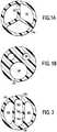
- the internal lumens of existing multiple-lumen PICCare generally configured as represented in FIGs. 1A and 1B .
- the lumens 110are formed by three septa 120 arranged radially, extending from the outer wall 130 of the catheter to the center of the catheter. Angular corners are formed at the intersection between the septa 120, and between each of the septum 120 and the outer wall 130 of the catheter.
- one of the lumensmust be used to thread the guide wire.
- the angular corners in the catheter lumenshave a tendency to catch the guide wire, and make PICC placement difficult.
- the radially arranged lumens 110 in FIG. 1Aalso do not perform well under pressure.
- the angular corners of the lumensare prone to rupture under pressure.
- a practitionermay have to increase the diameter of the inner lumen by increasing the overall diameter of the PICC.
- the multiple-lumen PICCs that are currently available on the marketare generally of large diameters, typically 6 Fr or larger.
- the relatively large size of the existing multiple-lumen PICCis not an ideal solution, because it would make PICC placement more difficult and diminish the advantage of PICCs over central venous lines. Accordingly, it would be desirable to have a multiple-lumen PICC capable of use for power injection of diagnostic and therapeutic agents, while still having a traditional outer dimension and being configured (without small angular corners) for easy insertion over a guide wire.
- WO98/24501discloses a multiple lumen access device for use in providing a single entry port into the human body for selectively introducing medical implements therethrough and for providing simultaneous auxiliary access into the body.
- the multiple lumen access deviceincludes a multiple lumen sheath which may have an outer tube and structure defining a device lumen located therein.
- the inner structuremay be an inner tube.
- the outer tube and inner structureare located so as to define at least one auxiliary lumen which may be located between the exterior surface of the inner tube and the interior surface of the outer tube.
- Embodimentsinclude flexible inner tubes which can be flexed between relaxed and expanded/contracted positions wherein the relative cross-sectional areas of the device lumen and auxiliary lumens are varied.
- a multi-lumen catheter according to the present inventionis defined in independent claim 1. Preferred embodiments are defined in dependent claims 2 and 3.
- the present inventionpresents a multi-lumen intravenous catheter comprising an elongated body portion having an outer wall extending longitudinally between proximal and distal ends, wherein two septa extend longitudinally through the elongated body portion, the septa and the outer wall define a central lumen and two side lumens, the central lumen has a generally oblong shape in cross section and is positioned between the two side lumens; and a plurality of extension tubes, each having a first end and a second end, extending generally longitudinally away from the proximal end of the body portion, wherein the first ends of the extension tubes connect to the proximal end of the body portion, the central lumen and the two side lumens each form a fluid tight connection to a respective extension tube, wherein the central lumen has planar side surfaces, a rounded top, a rounded bottom, wherein each of the side lumens has a "D" shape in cross section, wherein at least one of the side lumens is configured to receive
- the present invention multi-lumen cathetermay further comprise a plurality of connectors, wherein a connector is located at a second end of each of the extension tubes,
- a radius of curvature of an inner surface of each of the side lumensis in all locations equal to or greater than a radius of curvature of an outer wall of a guide wire used for insertion of the multi-lumen catheter.
- a minimal thickness of the outer wall that bounds the central lumenmaybe larger than a thickness of each of the septa.
- the outer wallis more rupture resistant than either of the septa,
- Each of the septais configured to have less mechanical strength under catheter pressure than the outer wall, whereby catheter rupture will occur in one or both of the septa prior to in the outer wall.
- Each of the septaIs configured to fail under catheter pressure before failure of the outer wall.
- the sum of the cross sectional areas of the two side lumensis less than the cross sectional area of the central lumen. In another embodiment of the present invention, the sum of the cross sectional areas of the two side lumens does not equal the cross sectional area of the central lumen.
- the proximal end 230 of the body portion 220 of the catheterconnects to a plurality of extension tubes 231 232 233.
- Each of the internal lumenforms a fluid tight connection to an extension tube 231 232 233.
- more than one lumencan be connected to a single extension tube.
- Each of the extension tube 231 232 233further may connect to a connector of a type commonly used in medical applications 241 242 243, such as Luer-Lock type connectors, which provides easy linkage to other medical instruments or devices.
- Connectors for the present invention multiple-lumen cathetermay be manufactured separately from the catheter, and are attached during insertion of the catheter assembly.
- Clamps 251 252 253may be placed on the extension tubes to stop fluid flow when the catheter is not in use.
- the body portion 220 of catheteris usually made of material that is flexible, such as silicone or polyurethane or other tissue compatible polymers.
- Poiseuille's Lawprovides important guidance to approximate fluid flow characteristics within a multiple-lumen catheter where the walls may flex and expand slightly under pressure.
- FIG. 3shows a cross section view of the catheter body of one embodiment of the present invention.
- Two septa 304divide the internal space of the body portion 220 into three lumens 302 303.
- the lumensare arranged in a side-by-side configuration.
- the central lumen 303is located essentially in the center of the catheter body, and the two side lumens 302 are located on each side of the central lumen 303.
- the central lumen 303is defined by the two septa 304 and the outer wall 301 of the catheter, and is positioned between the two side lumens 302.
- the central lumen 303has a generally stadium shape in cross section. In the embodiment shown in FIG.
- the central lumen 303is formed by septa with essentially planar side surfaces 306, and rounded top and bottom surfaces 305.
- the central lumen 303may have a cross section of an elongated circle, an ellipse, or other shapes that efficiently utilizes the internal space of the catheter.
- the side lumens 302have a crescent or "D" shape in cross section.
- the side lumens 302can have circular, elliptical, "C" shaped, or other suitable cross sections.
- the shape of the cross sections of the central lumen 303 and side lumens 302is chosen so that it provides optimal utilization of the internal space of the body portion 220 of the catheter.
- the rounded top and bottom surface 305 of the central lumen 303 and the outer surface 307 of the catheter body portion 220forms the outer wall 301 of the catheter body portion 220.
- the rounded top and bottom interior surface of the central lumen 305connects smoothly to the side surfaces 306.
- the inner surface 305 306 of the central lumen 303is free from any sharp corners.
- the smooth inner surface 305 306 of the central lumen 303is optimal for catheter placement along a guide wire.
- the radius of curvature of the inner surface 305is chosen to minimize the possibility that any corner within the central lumen 303 can catch the guide wire and hinder the advance of the catheter 200 along the guide wire. For example, if a guide wire of 0.046 cm (0.018 in.) diameter is intended, the radius of curvature for any corner in the central lumen 303 would preferably be equal to or larger than 0.023 cm (0.009 in).
- the radius of curvature within the central lumen 303is in all locations (i.e., at all points along the inner wall of the central lumen 303 and/or the side lumens 302) equal to or greater than the radius of curvature of the outer wall (or outer perimeter surface) of an associated guide wire.
- FIG. 4shows a cross section view of an example of a multi-lumen catheter not forming part of the invention.
- the two side lumens 402are of a generally circular shape.
- the central lumen 403is of a "dog bone" shape.
- the top and bottom interior surfaces 405 of the central lumen of the embodiment shown in FIG. 4connect smoothly to the side surfaces 406.
- the entire interior surface 405 406 of the central lumen 403is free of sharp corners.
- the septa 404 between the two side lumens 402 and the central lumen 403protrude into the central lumen 403 at normal atmospheric pressure, i.e., the septa 404 are of generally concave shape.
- the septa 404When under pressure, such as during power injection procedure, the septa 404 are capable of deforming and may be pushed outward.
- the septa 404may adopt convex shape under pressure.
- the potential to deform and expand the diameter of the central lumen 403provides the present invention excellent flow performance when the overall exterior diameter is of a small size.
- the outer wall 401 of the cathetercan be made thicker at the top and bottom of the central lumen than the septa 404. This configuration would help to provide stronger mechanical strength to the exterior wall of the catheter body 220.
- FIG. 5shows a cross section view of catheter body of another example of a multi-lumen catheter not forming part of the invention.
- the central lumen 503is of a "hour glass" shape.
- the two side lumens 502are of irregular elliptical shape having the interior surface 508 following the general shape of the side surfaces 506 of the central lumen 506.
- the septa 504 between the two side lumens 502 and the central lumen 503protrude into the central lumen 503 under normal atmospheric pressure, i.e., the septa 504 are of generally concave shape. When under pressure, such as during power injection procedure, the septa 504 are capable of deforming and may be pushed outward.
- the septa 504would adopt convex shape under pressure.
- the outer wall 501 of the cathetercan be made thicker at the top and bottom of the central lumen than the septa 504. This configuration would help to provide stronger mechanical strength to the exterior wall of the catheter body 220.
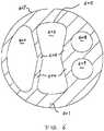
- FIG. 6shows a cross section view of the catheter body of another example of a multi-lumen catheter not forming part of the invention.
- two smaller side lumens 608 609are formed.
- This lumen configurationcan be adapted to all examples of the present application, which include, but are not limited to, the embodiments disclosed in FIGs. 4 and 5 .
- a guide wireis preferably traversed through one of the respective side lumens 402 502 602 when used to advance the catheter.
- the radius of curvature within the side lumen 402 502 602is in all locations (i.e., at all points along the inner wall of the side lumen 402 502 602) equal to or greater than the radius of curvature of the outer wall (or outer perimeter surface) of an associated guide wire.
- the central lumen of the present invention 303 403 503 603,has a large cross section (or cross-sectional area) relative to the available space (or cross-sectional area) within the body portion 220 of the catheter. Because the flow rate is proportional to the fourth power of the radius of a tube, even a small increase in the cross section of the central lumen 303 403 503 603 greatly increases the flow rate achievable though the tube when all other parameters are constant.
- the present inventionoptimizes space utilization within the body portion 220 of the catheter, allowing the body portion 220 to have a relatively thick outer wall 301. This increases the mechanical strength of the body portion 220, and in turn allows a higher pressure rating for the catheter 200. When the catheter 200 is under pressure, each of the septa 304 404 504 604 may flex outward, resultantly increasing the cross section of the central lumen 303 403 503 603, and thereby further facilitating fluid flow.
- the septa 304 of the present invention and of the examples 404 504 604is designed to have less mechanical strength than the outer wall 301 401 501 601 of the catheter body portion 220.
- the septa 304 404 504 604are of a thickness less than the minimal thickness of the outer wall 301 401 501 601.
- the rupture characteristics of the septa 304 404 504 604 and the outer wall 301 401 501 601are optimized by modifying both the thickness and the shape. This provides a fail-safe mechanism.
- one or both of the septa 304 404 504 604would be first to rupture (relative to the outer wall 301 401 501 601).
- a septum 304 404 504 604 breachoccurs, the fluid within the central lumen 303 403 503 603 would therefore leak into a side lumen 302 402 502 602 608 609. Accordingly, the integrity of the body portion 220 of the catheter 200 is retained.
- This configurationeffectively protects against extravastation of the fluid within the central lumen 303 403 503 603 in the event of a septa 304 404 504 604 breach.
- the configuration of the central lumen 303 of the present invention and of the examples 403 503 603provides high flow rate and fail safe protection under pressure. It is, therefore, suited for power injection of diagnostic or therapeutic agents.
- the catheter of the present inventioncan be safely used at a flow rate of 5 cc/sec at 300 psi.
- the configuration of the lumensalso provide added benefits such as kink resistance and flexibility.
- the lumens of the present invention catheterare intended to be used independently to deliver drugs, therapeutic or diagnostic agents.
- the dimensions of the lumensare not necessarily constrained in relation to one another.
- the cross sectional area of the central lumen 304 404 504 604may or may not be equal to the sum of the cross sectional areas of the side lumens 302 402 502 602 608 609.
- the sum of the cross sectional areas of the two side lumens 302 of the present invention and of the examples 402 502 602 608 609is greater than the cross sectional area of the central lumen 303 403 503 603.
- the sum of the cross sectional areas of the two side lumens 302 402 502 602is less than the cross sectional area of the central lumen 303 403 503 603.
- the present invention cathetercan be manufactured to various sizes suitable for PICC application.
- the unique lumen configuration of the present inventionmakes it possible to manufacture triple lumen PICC with small outer diameters such as French size 5 or 6.
- the catheters of the present inventioncan be made from existing thermal plastics presently used for intravenous catheters, such as silicone and polyurethane or other tissue compatible polymers.
- the body portion of the catheter of the present inventioncan be manufactured using existing molding or extrusion manufacturing processes. Placement of the catheters of the present invention also does not require any special modification to present medical procedures.
Landscapes
- Health & Medical Sciences (AREA)
- Life Sciences & Earth Sciences (AREA)
- Biomedical Technology (AREA)
- Heart & Thoracic Surgery (AREA)
- Biophysics (AREA)
- Pulmonology (AREA)
- Engineering & Computer Science (AREA)
- Anesthesiology (AREA)
- Veterinary Medicine (AREA)
- Public Health (AREA)
- Hematology (AREA)
- Animal Behavior & Ethology (AREA)
- General Health & Medical Sciences (AREA)
- Geometry (AREA)
- Physics & Mathematics (AREA)
- Media Introduction/Drainage Providing Device (AREA)
Description
- This invention relates to catheters that are inserted into a patient's body for diagnostic or therapeutic purposes. The invention specially relates to multiple-lumen intravenous catheters that are suitable, as one of the intended applications, for pressurized injection of diagnostic and therapeutic agents.
- Infusion of drugs, medications, or other diagnostic and therapeutic agents into the vascular system of a patient is a task routinely required by modern medicine. Placement of central venous access devices is a common occurrence in hospitals for these purposes. They are essentially used to give intra venous medications, obtain venous samples of blood and obtain measurements of central venous pressure. Three of the most commonly used devices are the Totally Implantable Venous Access System (TIVAS), the Peripherally Inserted Central Catheter (PICC), and the Central Venous Catheter. A TIVAS usually consists of a reservoir compartment (the portal) that has a silicone bubble for needle insertion (the septum), with an attached plastic tube (the catheter). The device is surgically inserted under the skin in the upper chest or in the arm, and the catheter is inserted into a vein. A PICC is inserted in a peripheral vein, such as the cephalic vein, basilic vein, or brachial vein and then advanced through increasingly larger veins, toward the heart until the tip rests in the distal superior vena cava or cavo-atrial junction. The proximal end of the PICC remains outside of the body. Central venous catheter is also referred to as a chest catheter or a Hickman line. The distal end of the catheter enters the jugular vein and advances into the superior vena cava. The proximal end of the catheter tunnels under the skin and exits on the chest wall. When inserting a PICC or Hickman line, a stainless steel wire (guide wire) is used to guide the flexible catheter through the vasculature to its intended site of placement.
- Angiography is a medical imaging technique in which an X-ray picture is taken to visualize the inner opening of blood filled structures, including arteries, veins and the heart chambers. Computed tomography (CT) technique can also be used to generate detailed three dimensional images. Because blood has the same radiodensity as the surrounding tissues, a radio-contrast agent is added to the blood to make angiography visualization possible. A large amount of contrast agent infused in a short period of time is usually necessary for successfully obtaining images with good contrast. Power injection equipment is routinely employed with central venous access catheters to achieve the required rate of delivery. Clinical injection rates can go as high as 5mL/sec. Other medical procedures, such as in the treatment of dehydration and sepsis, may also require infusion of large amounts of fluid through a central venous line.
- PICC insertion is less traumatic compared to a central venous catheter. Multiple-lumen catheters have the distinct advantage of enabling multiple diagnostic and therapeutic access through a single placement procedure. Some patients undergoing imaging examinations may already have a PICC placed for other purposes. Insertion of a traditional central venous catheter solely for the purpose of imaging examination can be traumatic for the patients and cumbersome for the medical staff.
- Existing multiple-lumen PICCs may be used for power injection of diagnostic and therapeutic agents. The internal lumens of existing multiple-lumen PICC are generally configured as represented in
FIGs. 1A and 1B . In the PICC depicted inFIG. 1A , thelumens 110 are formed by threesepta 120 arranged radially, extending from theouter wall 130 of the catheter to the center of the catheter. Angular corners are formed at the intersection between thesepta 120, and between each of theseptum 120 and theouter wall 130 of the catheter. During the placement of a PICC, one of the lumens must be used to thread the guide wire. The angular corners in the catheter lumens have a tendency to catch the guide wire, and make PICC placement difficult. The radially arrangedlumens 110 inFIG. 1A also do not perform well under pressure. The angular corners of the lumens are prone to rupture under pressure. FIG. 1B depicts the cross section of another example of a multiple-lumen catheter having three lumens with circular cross sections. Alarger lumen 140 is formed on one side of the catheter, with twosmaller lumens 150 on the other side. Thelarger lumen 140, which lacks any angular corners, is naturally suited to be used with the guide wire for advancement of the PICC. However, the diameter of thelarger lumen 140 is relatively small compared to the usable space within the body of the catheter. As can be seen when viewing theFIG. 1B embodiment, the use of space is not very efficient. The small diameter of thelarger lumen 140 also restricts the maximum flow rate achievable through this lumen. High pressure resulting from the required flow rate for power injection would reach unsafe levels that may cause catheter rupture. Further, the structural weak point of the larger lumen is itsouter wall 160. In the event of a catheter rupture, theouter wall 160 of thelarger lumen 140 is the likely place to breach. Fluid in thelarger lumen 140 may escape into the surrounding tissue, and cause complications. For the foregoing reasons, a PICC with theFIG. 1B configuration is generally not suitable for power injection.- To increase the pressure rating for the multiple-lumen PICCs with the aforementioned existing lumen configurations, a practitioner may have to increase the diameter of the inner lumen by increasing the overall diameter of the PICC. The multiple-lumen PICCs that are currently available on the market are generally of large diameters, typically 6 Fr or larger. The relatively large size of the existing multiple-lumen PICC is not an ideal solution, because it would make PICC placement more difficult and diminish the advantage of PICCs over central venous lines. Accordingly, it would be desirable to have a multiple-lumen PICC capable of use for power injection of diagnostic and therapeutic agents, while still having a traditional outer dimension and being configured (without small angular corners) for easy insertion over a guide wire. Particularly it would be desirable to have a triple lumen power injection PICC with an outer diameter of 5 Fr or less. Additionally, it would be desirable to have a multiple-lumen PICC that is fail safe. In ease of a lumen rupture when the catheter is used under pressure, the integrity of the exterior wall is retained.
WO98/24501 - A multi-lumen catheter according to the present invention is defined in independent claim 1. Preferred embodiments are defined in dependent claims 2 and 3.
- Accordingly, the present invention presents a multi-lumen intravenous catheter comprising an elongated body portion having an outer wall extending longitudinally between proximal and distal ends, wherein two septa extend longitudinally through the elongated body portion, the septa and the outer wall define a central lumen and two side lumens, the central lumen has a generally oblong shape in cross section and is positioned between the two side lumens; and a plurality of extension tubes, each having a first end and a second end, extending generally longitudinally away from the proximal end of the body portion, wherein the first ends of the extension tubes connect to the proximal end of the body portion, the central lumen and the two side lumens each form a fluid tight connection to a respective extension tube, wherein the central lumen has planar side surfaces, a rounded top, a rounded bottom, wherein each of the side lumens has a "D" shape in cross section, wherein at least one of the side lumens is configured to receive a guide wire, wherein each of the two septa are configured to flex when the central lumen is under pressure generated by injection of fluid there-through, whereby a cross sectional area of the central lumen resultantly increases to increase flow capacity through the central lumen, each of the two septa have less mechanical strength than the outer wall, whereby catheter rupture will occur in one or both of the septa prior to in the outer wall, and when the rupture occurs in at least one of the two septa, the fluid within the central lumen therefore leaks into at least one of the two side lumens.
- The present invention multi-lumen catheter may further comprise a plurality of connectors, wherein a connector is located at a second end of each of the extension tubes,
- In one embodiment of the present invention, a radius of curvature of an inner surface of each of the side lumens is in all locations equal to or greater than a radius of curvature of an outer wall of a guide wire used for insertion of the multi-lumen catheter.
- In one embodiment of the present invention, a minimal thickness of the outer wall that bounds the central lumen maybe larger than a thickness of each of the septa. The outer wall is more rupture resistant than either of the septa, Each of the septa is configured to have less mechanical strength under catheter pressure than the outer wall, whereby catheter rupture will occur in one or both of the septa prior to in the outer wall. Each of the septa Is configured to fail under catheter pressure before failure of the outer wall.
- In one embodiment of the present invention, the sum of the cross sectional areas of the two side lumens is less than the cross sectional area of the central lumen. In another embodiment of the present invention, the sum of the cross sectional areas of the two side lumens does not equal the cross sectional area of the central lumen.
FIG. 1A and FIG. 1B are schematic cross section views of existing, prior art triple lumen catheters;FIG. 2 is a diagrammatic side view of one embodiment of a multiple-lumen catheter;FIG. 3 is a schematic cross section view of the body portion of one embodiment of the present invention multiple lumen catheter,FIG. 4 is a schematic cross section view of the body portion of an example of a multiple lumen catheter not within the scope of the claims,FIG. 5 is a schematic cross section view of the body portion of another example of a multiple lumen catheter not within the scope of the claims, andFIG. 6 is a schematic cross section view of the body portion of another example of a multiple lumen catheter not within the scope of the claims.- The advantages of the present invention will be apparent to those skilled in the art from the following specification. Accordingly, it will be recognized by those skilled in the art that changes or modifications may be made to the below-described embodiments without departing from the broad inventive concepts of the invention as defined by the appended claims. It should therefore be understood that this invention is not limited to the particular embodiments described herein, but is intended to include all changes and modifications that are within the scope of the invention as defined by the appended claims. The words "proximal" and "distal" refer to directions away from and closer to the insertion tip, respectively, of a catheter of the present invention.
FIG. 2 depicts a representative multiple-lumen catheter 200 employing the present invention lumen configuration. The catheter comprises anelongated body portion 220. In the distal end, thebody portion 220 connects to atip structure 210. The internal space of thebody portion 220 is divided into several lumens. Each of the lumens has an opening in thetip structure 210. In the embodiment shown inFIG. 2 , each of the lumens opens at the same point of thetip structure 210. In other embodiments of the present invention, openings of each of the lumens may be placed at different locations along thetip structure 210, thereby minimizing mixing and the possibility of adverse reactions when incompatible drugs or therapeutic agents are delivered at the same time through separate lumens of the catheter. Other tip structure well known in the art can also be used with the present invention. Theproximal end 230 of thebody portion 220 of the catheter connects to a plurality ofextension tubes 231 232 233. Each of the internal lumen forms a fluid tight connection to anextension tube 231 232 233. In some embodiments of the present invention more than one lumen can be connected to a single extension tube. Each of theextension tube 231 232 233 further may connect to a connector of a type commonly used inmedical applications 241 242 243, such as Luer-Lock type connectors, which provides easy linkage to other medical instruments or devices. Connectors for the present invention multiple-lumen catheter may be manufactured separately from the catheter, and are
attached during insertion of the catheter assembly.Clamps 251 252 253 may be placed on the extension tubes to stop fluid flow when the catheter is not in use.- The pressure generated by injection of fluid though a rigid tube can be described by Poiseuille's Law, which states that: Q = (πr4ΔP)/(η8L), The rate of flow through a rigid tube (Q) is proportional to the fourth power of the radius of the tube (r) and the difference in pressure at the two ends of the tube (ΔP), and is inversely related to the viscosity of the fluid (η) and the length of the tube (L). The
body portion 220 of catheter is usually made of material that is flexible, such as silicone or polyurethane or other tissue compatible polymers. Although not directly applicable, Poiseuille's Law provides important guidance to approximate fluid flow characteristics within a multiple-lumen catheter where the walls may flex and expand slightly under pressure. FIG. 3 shows a cross section view of the catheter body of one embodiment of the present invention. Twosepta 304 divide the internal space of thebody portion 220 into threelumens 302 303. The lumens are arranged in a side-by-side configuration. Thecentral lumen 303 is located essentially in the center of the catheter body, and the twoside lumens 302 are located on each side of thecentral lumen 303. Thecentral lumen 303 is defined by the twosepta 304 and theouter wall 301 of the catheter, and is positioned between the twoside lumens 302. Thecentral lumen 303 has a generally stadium shape in cross section. In the embodiment shown inFIG. 3 , thecentral lumen 303 is formed by septa with essentially planar side surfaces 306, and rounded top and bottom surfaces 305. In other embodiments, thecentral lumen 303 may have a cross section of an elongated circle, an ellipse, or other shapes that efficiently utilizes the internal space of the catheter. In the embodiment shown inFIG. 3 , theside lumens 302 have a crescent or "D" shape in cross section. In other examples not forming part of the invention, theside lumens 302 can have circular, elliptical, "C" shaped, or other suitable cross sections. The shape of the cross sections of thecentral lumen 303 andside lumens 302 is chosen so that it provides optimal utilization of the internal space of thebody portion 220 of the catheter. The rounded top andbottom surface 305 of thecentral lumen 303 and theouter surface 307 of thecatheter body portion 220 forms theouter wall 301 of thecatheter body portion 220.- The rounded top and bottom interior surface of the
central lumen 305 connects smoothly to the side surfaces 306. Theinner surface 305 306 of thecentral lumen 303 is free from any sharp corners. The smoothinner surface 305 306 of thecentral lumen 303 is optimal for catheter placement along a guide wire. The radius of curvature of theinner surface 305 is chosen to minimize the possibility that any corner within thecentral lumen 303 can catch the guide wire and hinder the advance of thecatheter 200 along the guide wire. For example, if a guide wire of 0.046 cm (0.018 in.) diameter is intended, the radius of curvature for any corner in thecentral lumen 303 would preferably be equal to or larger than 0.023 cm (0.009 in). Accordingly, in one aspect of the invention, the radius of curvature within the central lumen 303 (and/or within the side lumens 302) is in all locations (i.e., at all points along the inner wall of thecentral lumen 303 and/or the side lumens 302) equal to or greater than the radius of curvature of the outer wall (or outer perimeter surface) of an associated guide wire. FIG. 4 shows a cross section view of an example of a multi-lumen catheter not forming part of the invention. In this particular example, the twoside lumens 402 are of a generally circular shape. And thecentral lumen 403 is of a "dog bone" shape. The top and bottominterior surfaces 405 of the central lumen of the embodiment shown inFIG. 4 connect smoothly to the side surfaces 406. The entireinterior surface 405 406 of thecentral lumen 403 is free of sharp corners. Thesepta 404 between the twoside lumens 402 and thecentral lumen 403 protrude into thecentral lumen 403 at normal atmospheric pressure, i.e., thesepta 404 are of generally concave shape. When under pressure, such as during power injection procedure, thesepta 404 are capable of deforming and may be pushed outward. Theside lumens 402, as a consequence, may have reduced size under pressure. Thus, thesepta 404 may adopt convex shape under pressure. The potential to deform and expand the diameter of thecentral lumen 403 provides the present invention excellent flow performance when the overall exterior diameter is of a small size. Theouter wall 401 of the catheter can be made thicker at the top and bottom of the central lumen than thesepta 404. This configuration would help to provide stronger mechanical strength to the exterior wall of thecatheter body 220.FIG. 5 shows a cross section view of catheter body of another example of a multi-lumen catheter not forming part of the invention. In this particular example, thecentral lumen 503 is of a "hour glass" shape. The twoside lumens 502 are of irregular elliptical shape having theinterior surface 508 following the general shape of the side surfaces 506 of thecentral lumen 506. Similar to the example shown inFIG. 4 , thesepta 504 between the twoside lumens 502 and thecentral lumen 503 protrude into thecentral lumen 503 under normal atmospheric pressure, i.e., thesepta 504 are of generally concave shape. When under pressure, such as during power injection procedure, thesepta 504 are capable of deforming and may be pushed outward. Thus, thesepta 504 would adopt convex shape under pressure. Similarly, theouter wall 501 of the catheter can be made thicker at the top and bottom of the central lumen than thesepta 504. This configuration would help to provide stronger mechanical strength to the exterior wall of thecatheter body 220.FIG. 6 shows a cross section view of the catheter body of another example of a multi-lumen catheter not forming part of the invention. In this particular example, instead of one side lumen on one side of thecentral lumen 603, twosmaller side lumens 608 609 are formed. This lumen configuration can be adapted to all examples of the present application, which include, but are not limited to, the embodiments disclosed inFIGs. 4 and5 .- For the lumen configurations shown in
FIG. 4 ,5 , and6 , a guide wire is preferably traversed through one of therespective side lumens 402 502 602 when used to advance the catheter. The radius of curvature within theside lumen 402 502 602 is in all locations (i.e., at all points along the inner wall of theside lumen 402 502 602) equal to or greater than the radius of curvature of the outer wall (or outer perimeter surface) of an associated guide wire. - The central lumen of the
present invention 303 403 503 603, has a large cross section (or cross-sectional area) relative to the available space (or cross-sectional area) within thebody portion 220 of the catheter. Because the flow rate is proportional to the fourth power of the radius of a tube, even a small increase in the cross section of thecentral lumen 303 403 503 603 greatly increases the flow rate achievable though the tube when all other parameters are constant. The present invention optimizes space utilization within thebody portion 220 of the catheter, allowing thebody portion 220 to have a relatively thickouter wall 301. This increases the mechanical strength of thebody portion 220, and in turn allows a higher pressure rating for thecatheter 200. When thecatheter 200 is under pressure, each of thesepta 304 404 504 604 may flex outward, resultantly increasing the cross section of thecentral lumen 303 403 503 603, and thereby further facilitating fluid flow. - One shortcoming of existing multiple lumen catheter designs is that the exterior wall of the respective catheter tends to rupture first (relative to other catheter walls) when under pressure. In one aspect, the
septa 304 of the present invention and of the examples 404 504 604 is designed to have less mechanical strength than theouter wall 301 401 501 601 of thecatheter body portion 220. In another aspect, thesepta 304 404 504 604 are of a thickness less than the minimal thickness of theouter wall 301 401 501 601. In still another aspect, the rupture characteristics of thesepta 304 404 504 604 and theouter wall 301 401 501 601 are optimized by modifying both the thickness and the shape. This provides a fail-safe mechanism. In the event of catheter malfunction, such as a blockage, one or both of thesepta 304 404 504 604 would be first to rupture (relative to theouter wall 301 401 501 601). When aseptum 304 404 504 604 breach occurs, the fluid within thecentral lumen 303 403 503 603 would therefore leak into aside lumen 302 402 502 602 608 609. Accordingly, the integrity of thebody portion 220 of thecatheter 200 is retained. This configuration effectively protects against extravastation of the fluid within thecentral lumen 303 403 503 603 in the event of asepta 304 404 504 604 breach. - The configuration of the
central lumen 303 of the present invention and of the examples 403 503 603 provides high flow rate and fail safe protection under pressure. It is, therefore, suited for power injection of diagnostic or therapeutic agents. The catheter of the present invention can be safely used at a flow rate of 5 cc/sec at 300 psi. The configuration of the lumens also provide added benefits such as kink resistance and flexibility. - The lumens of the present invention catheter are intended to be used independently to deliver drugs, therapeutic or diagnostic agents. The dimensions of the lumens are not necessarily constrained in relation to one another. The cross sectional area of the
central lumen 304 404 504 604 may or may not be equal to the sum of the cross sectional areas of theside lumens 302 402 502 602 608 609. In one variation of the present invention and of the examples, the sum of the cross sectional areas of the twoside lumens 302 of the present invention and of the examples 402 502 602 608 609 is greater than the cross sectional area of thecentral lumen 303 403 503 603. In another variation, the sum of the cross sectional areas of the twoside lumens 302 402 502 602 is less than the cross sectional area of thecentral lumen 303 403 503 603. - The present invention catheter can be manufactured to various sizes suitable for PICC application. The unique lumen configuration of the present invention makes it possible to manufacture triple lumen PICC with small outer diameters such as French size 5 or 6. The catheters of the present invention can be made from existing thermal plastics presently used for intravenous catheters, such as silicone and polyurethane or other tissue compatible polymers. The body portion of the catheter of the present invention can be manufactured using existing molding or extrusion manufacturing processes. Placement of the catheters of the present invention also does not require any special modification to present medical procedures.
Claims (3)
- A multi-lumen intravenous catheter comprising:an elongated body portion (220) having an outer wall (301, 401) extending longitudinally between proximal and distal ends, wherein:two septa (304, 404) extend longitudinally through the elongated body portion (220), wherein the two septa (304, 404) and the outer wall (301, 401) define a central lumen (303, 403) and two side lumens (302, 404), andthe central lumen has an oblong shape in cross section and is positioned between the two side lumens (302, 402); anda plurality of extension tubes (231-233), each having a first end and a second end, extending longitudinally away from the proximal end (230) of the body portion (220), wherein the first ends of the extension tubes (231-233) connect to the proximal end (230) of the body portion (220), the central lumen (303, 403) and the two side lumens (302, 402) each form a fluid tight connection to a respective extension tube,characterized in that:the central lumen has planar side surfaces (306), a rounded top, a rounded bottom,each of the side lumens (302, 304) have a "D" shape in cross section,at least one of the side lumen (302, 304) is configured to receive a guide wire,each of the two septa (304, 404) are configured to flex when the central lumen (303, 403) is under pressure generated by injection of fluid there-through, whereby a cross sectional area of the central lumen (303, 403) resultantly increases to increase flow capacity through the central lumen (303, 403),each of the two septa (304, 404) have less mechanical strength than the outer wall (301, 401), whereby catheter rupture will occur in one or both of the septa (304, 404) prior to in the outer wall (301, 401), andwhen a breach in one or both septa (304, 404) occurs, the fluid within the central lumen (303, 403) therefore leaks into one of the two side lumen (302, 402).
- The multi-lumen catheter (200) of claim 1, wherein a minimal thickness of the outer wall is larger than a thickness of each of the septa.
- The multi-lumen catheter of claim 1, wherein the sum of the cross sectional areas of the two side lumens is less than the cross sectional area of the central lumen.
Priority Applications (1)
| Application Number | Priority Date | Filing Date | Title |
|---|---|---|---|
| EP16170540.5AEP3078394A1 (en) | 2008-03-26 | 2009-03-26 | Triple lumen catheter |
Applications Claiming Priority (2)
| Application Number | Priority Date | Filing Date | Title |
|---|---|---|---|
| US3965508P | 2008-03-26 | 2008-03-26 | |
| PCT/US2009/038414WO2009120871A2 (en) | 2008-03-26 | 2009-03-26 | Triple lumen catheter |
Related Child Applications (2)
| Application Number | Title | Priority Date | Filing Date |
|---|---|---|---|
| EP16170540.5ADivision-IntoEP3078394A1 (en) | 2008-03-26 | 2009-03-26 | Triple lumen catheter |
| EP16170540.5ADivisionEP3078394A1 (en) | 2008-03-26 | 2009-03-26 | Triple lumen catheter |
Publications (3)
| Publication Number | Publication Date |
|---|---|
| EP2257332A2 EP2257332A2 (en) | 2010-12-08 |
| EP2257332A4 EP2257332A4 (en) | 2013-06-05 |
| EP2257332B1true EP2257332B1 (en) | 2018-07-04 |
Family
ID=41114719
Family Applications (2)
| Application Number | Title | Priority Date | Filing Date |
|---|---|---|---|
| EP16170540.5AWithdrawnEP3078394A1 (en) | 2008-03-26 | 2009-03-26 | Triple lumen catheter |
| EP09724674.8AActiveEP2257332B1 (en) | 2008-03-26 | 2009-03-26 | Triple lumen catheter |
Family Applications Before (1)
| Application Number | Title | Priority Date | Filing Date |
|---|---|---|---|
| EP16170540.5AWithdrawnEP3078394A1 (en) | 2008-03-26 | 2009-03-26 | Triple lumen catheter |
Country Status (4)
| Country | Link |
|---|---|
| US (1) | US9314586B2 (en) |
| EP (2) | EP3078394A1 (en) |
| ES (1) | ES2683894T3 (en) |
| WO (1) | WO2009120871A2 (en) |
Families Citing this family (32)
| Publication number | Priority date | Publication date | Assignee | Title |
|---|---|---|---|---|
| US8440122B2 (en) | 2005-06-30 | 2013-05-14 | Abbott Vascular Inc. | Introducer sheath and methods of making |
| US9168359B2 (en) | 2005-06-30 | 2015-10-27 | Abbott Laboratories | Modular introducer and exchange sheath |
| US9597063B2 (en)* | 2006-06-28 | 2017-03-21 | Abbott Laboratories | Expandable introducer sheath to preserve guidewire access |
| US8359723B2 (en) | 2005-06-30 | 2013-01-29 | Abbott Vascular Inc. | Introducer sheath and methods of making |
| US9352118B2 (en) | 2005-06-30 | 2016-05-31 | Abbott Laboratories | Modular introducer and exchange sheath |
| US8801744B2 (en) | 2006-06-28 | 2014-08-12 | Abbott Laboratories | Expandable introducer sheath to preserve guidewire access |
| US9889275B2 (en) | 2006-06-28 | 2018-02-13 | Abbott Laboratories | Expandable introducer sheath to preserve guidewire access |
| BR112013015031A2 (en) | 2010-12-15 | 2016-08-09 | Valeria Querol García | drainage system and drain hose |
| WO2012109462A2 (en) | 2011-02-10 | 2012-08-16 | C. R. Bard, Inc. | Multi-lumen catheter including an elliptical profile |
| US9717883B2 (en) | 2011-02-10 | 2017-08-01 | C. R. Bard, Inc. | Multi-lumen catheter with enhanced flow features |
| US8721588B2 (en)* | 2011-04-15 | 2014-05-13 | DePuy Synthes Products, LLC | Noncircular inner lumen guiding catheter with assisted variable support |
| US9700655B2 (en) | 2011-10-14 | 2017-07-11 | Ra Medical Systems, Inc. | Small flexible liquid core catheter for laser ablation in body lumens and methods for use |
| EP3549632B1 (en)* | 2012-05-25 | 2020-07-01 | C.R. Bard, Inc. | Multi-lumen catheter with enhanced flow features |
| US11273287B2 (en) | 2013-03-08 | 2022-03-15 | Endobar Solutions Llc | Selectively delivering particles into the distal portion of the left gastric artery |
| US9962527B2 (en) | 2013-10-16 | 2018-05-08 | Ra Medical Systems, Inc. | Methods and devices for treatment of stenosis of arteriovenous fistula shunts |
| GB2546167B (en) | 2013-12-17 | 2018-02-28 | Aslam Nasir Muhammed | Intubating Airway Device |
| GB2522403B (en)* | 2013-12-17 | 2017-09-13 | Aslam Nasir Muhammed | Airway device with flexible divider |
| USD1051359S1 (en) | 2015-06-15 | 2024-11-12 | Intersurgical Ag | Airway device |
| USD842456S1 (en) | 2015-12-15 | 2019-03-05 | Intersurgical Ag | Airway device |
| DE102015217061A1 (en)* | 2015-09-07 | 2017-03-09 | Raumedic Ag | tube |
| US20180289924A1 (en)* | 2015-10-28 | 2018-10-11 | Duke University | Catheters for debonding fouling agents from an interior surface thereof and related methods |
| US10555772B2 (en) | 2015-11-23 | 2020-02-11 | Ra Medical Systems, Inc. | Laser ablation catheters having expanded distal tip windows for efficient tissue ablation |
| CN109195656B (en)* | 2016-07-04 | 2022-06-07 | 株式会社钟化 | catheter |
| CN110430843B (en)* | 2017-03-14 | 2022-06-07 | 波士顿科学国际有限公司 | Medical device shaft including a liner |
| US10849787B2 (en)* | 2017-09-15 | 2020-12-01 | Rohit Khanna | Method and apparatus for treating the brain and/or spinal cord using a catheter |
| CN111278497B (en)* | 2017-11-28 | 2024-01-12 | 圣犹达医疗用品心脏病学部门有限公司 | Lumen control catheter |
| GB201720733D0 (en) | 2017-12-13 | 2018-01-24 | Ashkal Development Ltd | Airway device |
| JP2019166289A (en) | 2018-03-22 | 2019-10-03 | ラ メディカル システムズ, インコーポレイテッド | Liquid filled ablation catheter with overjacket |
| JP1649726S (en) | 2019-01-18 | 2020-01-14 | ||
| EP3958919B1 (en)* | 2019-04-23 | 2025-09-17 | Merit Medical Systems, Inc. | Drainage catheter with suture lumen |
| USD1025348S1 (en) | 2020-04-16 | 2024-04-30 | Intersurgical Ag | Airway device |
| US20240075247A1 (en)* | 2020-12-31 | 2024-03-07 | Nuwellis, Inc. | Dual lumen catheter |
Family Cites Families (13)
| Publication number | Priority date | Publication date | Assignee | Title |
|---|---|---|---|---|
| CA1330285C (en)* | 1987-12-22 | 1994-06-21 | Geoffrey S. Martin | Triple lumen catheter |
| NL9300231A (en)* | 1993-02-04 | 1994-09-01 | Cordis Europ | Angiography catheter. |
| US5348536A (en)* | 1993-08-02 | 1994-09-20 | Quinton Instrument Company | Coextruded catheter and method of forming |
| US5395316A (en)* | 1993-08-11 | 1995-03-07 | Med-Pro Design, Inc. | Triple lumen catheter |
| US5378230A (en)* | 1993-11-01 | 1995-01-03 | Mahurkar; Sakharam D. | Triple-lumen critical care catheter |
| EP0779790A1 (en)* | 1994-09-06 | 1997-06-25 | Sims Deltec, Inc. | Method and apparatus for location of a catheter tip |
| US5556390A (en)* | 1995-03-07 | 1996-09-17 | Quinton Instrument Company | Catheter with oval or elliptical lumens |
| CA2409240C (en) | 1996-11-26 | 2007-08-21 | Edwards Lifesciences Corporation | Multiple lumen access drive |
| US5947940A (en)* | 1997-06-23 | 1999-09-07 | Beisel; Robert F. | Catheter reinforced to prevent luminal collapse and tensile failure thereof |
| US6544251B1 (en)* | 1999-02-10 | 2003-04-08 | Michael K. Crawford | Peripherally inserted catheter |
| US7077829B2 (en)* | 2001-01-09 | 2006-07-18 | Rex Medical, L.P. | Dialysis catheter |
| EP1720595B1 (en)* | 2004-03-03 | 2011-05-11 | C.R.Bard, Inc. | Loop-tip catheter |
| US20090054874A1 (en)* | 2007-08-23 | 2009-02-26 | C. R. Bard, Inc. | Multi-lumen catheter including a lumen having a variable cross sectional area |
- 2009
- 2009-03-26ESES09724674.8Tpatent/ES2683894T3/enactiveActive
- 2009-03-26EPEP16170540.5Apatent/EP3078394A1/ennot_activeWithdrawn
- 2009-03-26EPEP09724674.8Apatent/EP2257332B1/enactiveActive
- 2009-03-26USUS12/411,813patent/US9314586B2/enactiveActive
- 2009-03-26WOPCT/US2009/038414patent/WO2009120871A2/enactiveApplication Filing
Non-Patent Citations (1)
| Title |
|---|
| None* |
Also Published As
| Publication number | Publication date |
|---|---|
| EP2257332A4 (en) | 2013-06-05 |
| WO2009120871A3 (en) | 2009-12-30 |
| ES2683894T3 (en) | 2018-09-28 |
| WO2009120871A2 (en) | 2009-10-01 |
| EP2257332A2 (en) | 2010-12-08 |
| US20090247868A1 (en) | 2009-10-01 |
| EP3078394A1 (en) | 2016-10-12 |
| US9314586B2 (en) | 2016-04-19 |
Similar Documents
| Publication | Publication Date | Title |
|---|---|---|
| EP2257332B1 (en) | Triple lumen catheter | |
| US12138405B2 (en) | Rapidly insertable central catheters, assemblies, and methods thereof | |
| EP1905476B1 (en) | Acute hemodialysis catheter assembly | |
| US9713694B2 (en) | Low profile catheter assembly | |
| US8574192B2 (en) | Catheter tunneling systems, instruments and methods | |
| US8137316B2 (en) | Sheathless insertion stylet system for catheter placement | |
| US7618411B2 (en) | Variable characteristic venous access catheter shaft | |
| US4559046A (en) | Apparatus for intravenous therapy and hyperalimentation | |
| US20050228364A1 (en) | Tunneler device | |
| US20110313399A1 (en) | Intravenous cannula | |
| WO2008109549A2 (en) | Catheter adapter apparatus | |
| CN112236181A (en) | Vein indwelling cannula | |
| US20150031977A1 (en) | Perfusion cannula with integrated sensor technology | |
| CN110496299A (en) | A double-lumen catheter for continuous purification of cerebrospinal fluid | |
| WO2002049511A1 (en) | Double lumen pigtail pressure monitoring catheter | |
| US20070073239A1 (en) | Catheter device | |
| CN223041904U (en) | Drainage and injection device | |
| EP1694396B1 (en) | Catheter with pump | |
| WO2024128586A1 (en) | Novel peripherally-inserted central catheter | |
| CN116920242A (en) | Anti-backflow device and intravenous drug delivery system for injecting chemical ablation agent | |
| CN119280623A (en) | A balloon catheter |
Legal Events
| Date | Code | Title | Description |
|---|---|---|---|
| PUAI | Public reference made under article 153(3) epc to a published international application that has entered the european phase | Free format text:ORIGINAL CODE: 0009012 | |
| 17P | Request for examination filed | Effective date:20100927 | |
| AK | Designated contracting states | Kind code of ref document:A2 Designated state(s):AT BE BG CH CY CZ DE DK EE ES FI FR GB GR HR HU IE IS IT LI LT LU LV MC MK MT NL NO PL PT RO SE SI SK TR | |
| AX | Request for extension of the european patent | Extension state:AL BA RS | |
| DAX | Request for extension of the european patent (deleted) | ||
| A4 | Supplementary search report drawn up and despatched | Effective date:20130507 | |
| RIC1 | Information provided on ipc code assigned before grant | Ipc:A61M 25/00 20060101ALI20130430BHEP Ipc:A61M 37/00 20060101AFI20130430BHEP | |
| 17Q | First examination report despatched | Effective date:20150318 | |
| GRAP | Despatch of communication of intention to grant a patent | Free format text:ORIGINAL CODE: EPIDOSNIGR1 | |
| STAA | Information on the status of an ep patent application or granted ep patent | Free format text:STATUS: GRANT OF PATENT IS INTENDED | |
| INTG | Intention to grant announced | Effective date:20170913 | |
| GRAJ | Information related to disapproval of communication of intention to grant by the applicant or resumption of examination proceedings by the epo deleted | Free format text:ORIGINAL CODE: EPIDOSDIGR1 | |
| STAA | Information on the status of an ep patent application or granted ep patent | Free format text:STATUS: EXAMINATION IS IN PROGRESS | |
| GRAS | Grant fee paid | Free format text:ORIGINAL CODE: EPIDOSNIGR3 | |
| STAA | Information on the status of an ep patent application or granted ep patent | Free format text:STATUS: GRANT OF PATENT IS INTENDED | |
| GRAP | Despatch of communication of intention to grant a patent | Free format text:ORIGINAL CODE: EPIDOSNIGR1 | |
| INTC | Intention to grant announced (deleted) | ||
| INTG | Intention to grant announced | Effective date:20180213 | |
| GRAA | (expected) grant | Free format text:ORIGINAL CODE: 0009210 | |
| STAA | Information on the status of an ep patent application or granted ep patent | Free format text:STATUS: THE PATENT HAS BEEN GRANTED | |
| AK | Designated contracting states | Kind code of ref document:B1 Designated state(s):AT BE BG CH CY CZ DE DK EE ES FI FR GB GR HR HU IE IS IT LI LT LU LV MC MK MT NL NO PL PT RO SE SI SK TR | |
| REG | Reference to a national code | Ref country code:GB Ref legal event code:FG4D | |
| REG | Reference to a national code | Ref country code:CH Ref legal event code:EP | |
| REG | Reference to a national code | Ref country code:AT Ref legal event code:REF Ref document number:1013833 Country of ref document:AT Kind code of ref document:T Effective date:20180715 | |
| REG | Reference to a national code | Ref country code:IE Ref legal event code:FG4D | |
| REG | Reference to a national code | Ref country code:DE Ref legal event code:R096 Ref document number:602009053038 Country of ref document:DE | |
| REG | Reference to a national code | Ref country code:ES Ref legal event code:FG2A Ref document number:2683894 Country of ref document:ES Kind code of ref document:T3 Effective date:20180928 | |
| REG | Reference to a national code | Ref country code:NL Ref legal event code:MP Effective date:20180704 | |
| REG | Reference to a national code | Ref country code:LT Ref legal event code:MG4D | |
| REG | Reference to a national code | Ref country code:AT Ref legal event code:MK05 Ref document number:1013833 Country of ref document:AT Kind code of ref document:T Effective date:20180704 | |
| PG25 | Lapsed in a contracting state [announced via postgrant information from national office to epo] | Ref country code:NL Free format text:LAPSE BECAUSE OF FAILURE TO SUBMIT A TRANSLATION OF THE DESCRIPTION OR TO PAY THE FEE WITHIN THE PRESCRIBED TIME-LIMIT Effective date:20180704 | |
| PG25 | Lapsed in a contracting state [announced via postgrant information from national office to epo] | Ref country code:IS Free format text:LAPSE BECAUSE OF FAILURE TO SUBMIT A TRANSLATION OF THE DESCRIPTION OR TO PAY THE FEE WITHIN THE PRESCRIBED TIME-LIMIT Effective date:20181104 Ref country code:NO Free format text:LAPSE BECAUSE OF FAILURE TO SUBMIT A TRANSLATION OF THE DESCRIPTION OR TO PAY THE FEE WITHIN THE PRESCRIBED TIME-LIMIT Effective date:20181004 Ref country code:AT Free format text:LAPSE BECAUSE OF FAILURE TO SUBMIT A TRANSLATION OF THE DESCRIPTION OR TO PAY THE FEE WITHIN THE PRESCRIBED TIME-LIMIT Effective date:20180704 Ref country code:PL Free format text:LAPSE BECAUSE OF FAILURE TO SUBMIT A TRANSLATION OF THE DESCRIPTION OR TO PAY THE FEE WITHIN THE PRESCRIBED TIME-LIMIT Effective date:20180704 Ref country code:BG Free format text:LAPSE BECAUSE OF FAILURE TO SUBMIT A TRANSLATION OF THE DESCRIPTION OR TO PAY THE FEE WITHIN THE PRESCRIBED TIME-LIMIT Effective date:20181004 Ref country code:LT Free format text:LAPSE BECAUSE OF FAILURE TO SUBMIT A TRANSLATION OF THE DESCRIPTION OR TO PAY THE FEE WITHIN THE PRESCRIBED TIME-LIMIT Effective date:20180704 Ref country code:CZ Free format text:LAPSE BECAUSE OF FAILURE TO SUBMIT A TRANSLATION OF THE DESCRIPTION OR TO PAY THE FEE WITHIN THE PRESCRIBED TIME-LIMIT Effective date:20180704 Ref country code:FI Free format text:LAPSE BECAUSE OF FAILURE TO SUBMIT A TRANSLATION OF THE DESCRIPTION OR TO PAY THE FEE WITHIN THE PRESCRIBED TIME-LIMIT Effective date:20180704 Ref country code:GR Free format text:LAPSE BECAUSE OF FAILURE TO SUBMIT A TRANSLATION OF THE DESCRIPTION OR TO PAY THE FEE WITHIN THE PRESCRIBED TIME-LIMIT Effective date:20181005 Ref country code:SE Free format text:LAPSE BECAUSE OF FAILURE TO SUBMIT A TRANSLATION OF THE DESCRIPTION OR TO PAY THE FEE WITHIN THE PRESCRIBED TIME-LIMIT Effective date:20180704 | |
| PG25 | Lapsed in a contracting state [announced via postgrant information from national office to epo] | Ref country code:LV Free format text:LAPSE BECAUSE OF FAILURE TO SUBMIT A TRANSLATION OF THE DESCRIPTION OR TO PAY THE FEE WITHIN THE PRESCRIBED TIME-LIMIT Effective date:20180704 Ref country code:HR Free format text:LAPSE BECAUSE OF FAILURE TO SUBMIT A TRANSLATION OF THE DESCRIPTION OR TO PAY THE FEE WITHIN THE PRESCRIBED TIME-LIMIT Effective date:20180704 | |
| REG | Reference to a national code | Ref country code:DE Ref legal event code:R097 Ref document number:602009053038 Country of ref document:DE | |
| PG25 | Lapsed in a contracting state [announced via postgrant information from national office to epo] | Ref country code:RO Free format text:LAPSE BECAUSE OF FAILURE TO SUBMIT A TRANSLATION OF THE DESCRIPTION OR TO PAY THE FEE WITHIN THE PRESCRIBED TIME-LIMIT Effective date:20180704 Ref country code:EE Free format text:LAPSE BECAUSE OF FAILURE TO SUBMIT A TRANSLATION OF THE DESCRIPTION OR TO PAY THE FEE WITHIN THE PRESCRIBED TIME-LIMIT Effective date:20180704 | |
| PLBE | No opposition filed within time limit | Free format text:ORIGINAL CODE: 0009261 | |
| STAA | Information on the status of an ep patent application or granted ep patent | Free format text:STATUS: NO OPPOSITION FILED WITHIN TIME LIMIT | |
| PG25 | Lapsed in a contracting state [announced via postgrant information from national office to epo] | Ref country code:SK Free format text:LAPSE BECAUSE OF FAILURE TO SUBMIT A TRANSLATION OF THE DESCRIPTION OR TO PAY THE FEE WITHIN THE PRESCRIBED TIME-LIMIT Effective date:20180704 Ref country code:DK Free format text:LAPSE BECAUSE OF FAILURE TO SUBMIT A TRANSLATION OF THE DESCRIPTION OR TO PAY THE FEE WITHIN THE PRESCRIBED TIME-LIMIT Effective date:20180704 | |
| 26N | No opposition filed | Effective date:20190405 | |
| PG25 | Lapsed in a contracting state [announced via postgrant information from national office to epo] | Ref country code:SI Free format text:LAPSE BECAUSE OF FAILURE TO SUBMIT A TRANSLATION OF THE DESCRIPTION OR TO PAY THE FEE WITHIN THE PRESCRIBED TIME-LIMIT Effective date:20180704 | |
| PG25 | Lapsed in a contracting state [announced via postgrant information from national office to epo] | Ref country code:MC Free format text:LAPSE BECAUSE OF FAILURE TO SUBMIT A TRANSLATION OF THE DESCRIPTION OR TO PAY THE FEE WITHIN THE PRESCRIBED TIME-LIMIT Effective date:20180704 | |
| REG | Reference to a national code | Ref country code:CH Ref legal event code:PL | |
| PG25 | Lapsed in a contracting state [announced via postgrant information from national office to epo] | Ref country code:LU Free format text:LAPSE BECAUSE OF NON-PAYMENT OF DUE FEES Effective date:20190326 | |
| REG | Reference to a national code | Ref country code:BE Ref legal event code:MM Effective date:20190331 | |
| PG25 | Lapsed in a contracting state [announced via postgrant information from national office to epo] | Ref country code:LI Free format text:LAPSE BECAUSE OF NON-PAYMENT OF DUE FEES Effective date:20190331 Ref country code:CH Free format text:LAPSE BECAUSE OF NON-PAYMENT OF DUE FEES Effective date:20190331 Ref country code:IE Free format text:LAPSE BECAUSE OF NON-PAYMENT OF DUE FEES Effective date:20190326 | |
| PG25 | Lapsed in a contracting state [announced via postgrant information from national office to epo] | Ref country code:BE Free format text:LAPSE BECAUSE OF NON-PAYMENT OF DUE FEES Effective date:20190331 | |
| PG25 | Lapsed in a contracting state [announced via postgrant information from national office to epo] | Ref country code:TR Free format text:LAPSE BECAUSE OF FAILURE TO SUBMIT A TRANSLATION OF THE DESCRIPTION OR TO PAY THE FEE WITHIN THE PRESCRIBED TIME-LIMIT Effective date:20180704 | |
| PG25 | Lapsed in a contracting state [announced via postgrant information from national office to epo] | Ref country code:PT Free format text:LAPSE BECAUSE OF FAILURE TO SUBMIT A TRANSLATION OF THE DESCRIPTION OR TO PAY THE FEE WITHIN THE PRESCRIBED TIME-LIMIT Effective date:20181105 Ref country code:MT Free format text:LAPSE BECAUSE OF NON-PAYMENT OF DUE FEES Effective date:20190326 | |
| PG25 | Lapsed in a contracting state [announced via postgrant information from national office to epo] | Ref country code:CY Free format text:LAPSE BECAUSE OF FAILURE TO SUBMIT A TRANSLATION OF THE DESCRIPTION OR TO PAY THE FEE WITHIN THE PRESCRIBED TIME-LIMIT Effective date:20180704 | |
| PG25 | Lapsed in a contracting state [announced via postgrant information from national office to epo] | Ref country code:HU Free format text:LAPSE BECAUSE OF FAILURE TO SUBMIT A TRANSLATION OF THE DESCRIPTION OR TO PAY THE FEE WITHIN THE PRESCRIBED TIME-LIMIT; INVALID AB INITIO Effective date:20090326 | |
| PG25 | Lapsed in a contracting state [announced via postgrant information from national office to epo] | Ref country code:MK Free format text:LAPSE BECAUSE OF FAILURE TO SUBMIT A TRANSLATION OF THE DESCRIPTION OR TO PAY THE FEE WITHIN THE PRESCRIBED TIME-LIMIT Effective date:20180704 | |
| PGFP | Annual fee paid to national office [announced via postgrant information from national office to epo] | Ref country code:DE Payment date:20231229 Year of fee payment:16 Ref country code:GB Payment date:20240108 Year of fee payment:16 | |
| PGFP | Annual fee paid to national office [announced via postgrant information from national office to epo] | Ref country code:IT Payment date:20240212 Year of fee payment:16 Ref country code:FR Payment date:20240103 Year of fee payment:16 | |
| PGFP | Annual fee paid to national office [announced via postgrant information from national office to epo] | Ref country code:ES Payment date:20240411 Year of fee payment:16 |