EP2257242B2 - Infundibular reducer devices - Google Patents
Infundibular reducer devicesDownload PDFInfo
- Publication number
- EP2257242B2 EP2257242B2EP09714661.7AEP09714661AEP2257242B2EP 2257242 B2EP2257242 B2EP 2257242B2EP 09714661 AEP09714661 AEP 09714661AEP 2257242 B2EP2257242 B2EP 2257242B2
- Authority
- EP
- European Patent Office
- Prior art keywords
- wires
- stent
- valve
- devices
- middle portion
- Prior art date
- Legal status (The legal status is an assumption and is not a legal conclusion. Google has not performed a legal analysis and makes no representation as to the accuracy of the status listed.)
- Active
Links
- 239000003638chemical reducing agentSubstances0.000titledescription24
- 239000000463materialSubstances0.000claimsdescription49
- 239000004744fabricSubstances0.000claimsdescription31
- 210000003709heart valveAnatomy0.000claimsdescription19
- 238000002513implantationMethods0.000claimsdescription10
- 210000002216heartAnatomy0.000claimsdescription8
- 210000003102pulmonary valveAnatomy0.000description15
- 230000002861ventricularEffects0.000description13
- 230000008901benefitEffects0.000description12
- 210000001519tissueAnatomy0.000description10
- BQCADISMDOOEFD-UHFFFAOYSA-NSilverChemical compound[Ag]BQCADISMDOOEFD-UHFFFAOYSA-N0.000description9
- 229910052709silverInorganic materials0.000description9
- 239000004332silverSubstances0.000description9
- 230000033001locomotionEffects0.000description8
- 241000283690Bos taurusSpecies0.000description7
- 210000003484anatomyAnatomy0.000description6
- 239000007943implantSubstances0.000description6
- 238000000034methodMethods0.000description6
- 230000017531blood circulationEffects0.000description5
- 230000000747cardiac effectEffects0.000description5
- 238000002594fluoroscopyMethods0.000description5
- 230000006870functionEffects0.000description5
- 230000002209hydrophobic effectEffects0.000description5
- 210000004731jugular veinAnatomy0.000description5
- 230000000052comparative effectEffects0.000description4
- 230000001788irregularEffects0.000description4
- 244000062175Fittonia argyroneuraSpecies0.000description3
- 208000007536ThrombosisDiseases0.000description3
- 208000015181infectious diseaseDiseases0.000description3
- 238000003780insertionMethods0.000description3
- 230000037431insertionEffects0.000description3
- 239000003550markerSubstances0.000description3
- 229920000642polymerPolymers0.000description3
- 238000001356surgical procedureMethods0.000description3
- 208000032750Device leakageDiseases0.000description2
- PXHVJJICTQNCMI-UHFFFAOYSA-NNickelChemical compound[Ni]PXHVJJICTQNCMI-UHFFFAOYSA-N0.000description2
- 229920010741Ultra High Molecular Weight Polyethylene (UHMWPE)Polymers0.000description2
- 238000004873anchoringMethods0.000description2
- 239000012620biological materialSubstances0.000description2
- 210000004204blood vesselAnatomy0.000description2
- 230000002612cardiopulmonary effectEffects0.000description2
- 230000004087circulationEffects0.000description2
- 230000006835compressionEffects0.000description2
- 238000007906compressionMethods0.000description2
- 230000005764inhibitory processEffects0.000description2
- 229910052751metalInorganic materials0.000description2
- 239000002184metalSubstances0.000description2
- 238000012544monitoring processMethods0.000description2
- 230000017066negative regulation of growthEffects0.000description2
- 230000035699permeabilityEffects0.000description2
- BASFCYQUMIYNBI-UHFFFAOYSA-NplatinumChemical group[Pt]BASFCYQUMIYNBI-UHFFFAOYSA-N0.000description2
- 230000002685pulmonary effectEffects0.000description2
- 210000002073venous valveAnatomy0.000description2
- 208000015121Cardiac valve diseaseDiseases0.000description1
- 102000008186CollagenHuman genes0.000description1
- 108010035532CollagenProteins0.000description1
- 229920000742CottonPolymers0.000description1
- 208000023281Fallot tetralogyDiseases0.000description1
- 108010010803GelatinProteins0.000description1
- SXRSQZLOMIGNAQ-UHFFFAOYSA-NGlutaraldehydeChemical compoundO=CCCCC=OSXRSQZLOMIGNAQ-UHFFFAOYSA-N0.000description1
- 239000004743PolypropyleneSubstances0.000description1
- FAPWRFPIFSIZLT-UHFFFAOYSA-MSodium chlorideChemical compound[Na+].[Cl-]FAPWRFPIFSIZLT-UHFFFAOYSA-M0.000description1
- 241000282898Sus scrofaSpecies0.000description1
- 201000003005Tetralogy of FallotDiseases0.000description1
- RTAQQCXQSZGOHL-UHFFFAOYSA-NTitaniumChemical compound[Ti]RTAQQCXQSZGOHL-UHFFFAOYSA-N0.000description1
- 238000004026adhesive bondingMethods0.000description1
- 230000000845anti-microbial effectEffects0.000description1
- 239000004599antimicrobialSubstances0.000description1
- 210000001765aortic valveAnatomy0.000description1
- 230000000712assemblyEffects0.000description1
- 238000000429assemblyMethods0.000description1
- 230000009286beneficial effectEffects0.000description1
- 239000008280bloodSubstances0.000description1
- 210000004369bloodAnatomy0.000description1
- 229920001436collagenPolymers0.000description1
- 238000010276constructionMethods0.000description1
- 230000007797corrosionEffects0.000description1
- 238000005260corrosionMethods0.000description1
- 230000006378damageEffects0.000description1
- 230000002950deficientEffects0.000description1
- 230000001419dependent effectEffects0.000description1
- 238000013461designMethods0.000description1
- 201000010099diseaseDiseases0.000description1
- 208000037265diseases, disorders, signs and symptomsDiseases0.000description1
- 238000009826distributionMethods0.000description1
- 210000003038endotheliumAnatomy0.000description1
- 229920000159gelatinPolymers0.000description1
- 235000019322gelatineNutrition0.000description1
- 235000011852gelatine dessertsNutrition0.000description1
- 238000002695general anesthesiaMethods0.000description1
- 208000019622heart diseaseDiseases0.000description1
- 229920001903high density polyethylenePolymers0.000description1
- 239000004700high-density polyethyleneSubstances0.000description1
- 230000036039immunityEffects0.000description1
- 238000012423maintenanceMethods0.000description1
- 238000004519manufacturing processMethods0.000description1
- 238000002844meltingMethods0.000description1
- 230000008018meltingEffects0.000description1
- 150000002739metalsChemical class0.000description1
- 238000013508migrationMethods0.000description1
- 230000005012migrationEffects0.000description1
- 238000002324minimally invasive surgeryMethods0.000description1
- 210000004115mitral valveAnatomy0.000description1
- 229910052759nickelInorganic materials0.000description1
- 229910001000nickel titaniumInorganic materials0.000description1
- 210000000056organAnatomy0.000description1
- 230000010412perfusionEffects0.000description1
- 210000003516pericardiumAnatomy0.000description1
- 229910052697platinumInorganic materials0.000description1
- 229920000728polyesterPolymers0.000description1
- -1polypropylenePolymers0.000description1
- 229920001155polypropylenePolymers0.000description1
- 229920002635polyurethanePolymers0.000description1
- 239000004814polyurethaneSubstances0.000description1
- 108090000623proteins and genesProteins0.000description1
- 102000004169proteins and genesHuman genes0.000description1
- 230000008439repair processEffects0.000description1
- 230000000717retained effectEffects0.000description1
- 238000007789sealingMethods0.000description1
- 238000004904shorteningMethods0.000description1
- 239000011780sodium chlorideSubstances0.000description1
- 241000894007speciesSpecies0.000description1
- 230000002966stenotic effectEffects0.000description1
- 238000003860storageMethods0.000description1
- 239000000126substanceSubstances0.000description1
- 239000003356suture materialSubstances0.000description1
- 239000010936titaniumSubstances0.000description1
- 229910052719titaniumInorganic materials0.000description1
- 210000000591tricuspid valveAnatomy0.000description1
- 230000002792vascularEffects0.000description1
- 210000003462veinAnatomy0.000description1
Images


Classifications
- A—HUMAN NECESSITIES
- A61—MEDICAL OR VETERINARY SCIENCE; HYGIENE
- A61F—FILTERS IMPLANTABLE INTO BLOOD VESSELS; PROSTHESES; DEVICES PROVIDING PATENCY TO, OR PREVENTING COLLAPSING OF, TUBULAR STRUCTURES OF THE BODY, e.g. STENTS; ORTHOPAEDIC, NURSING OR CONTRACEPTIVE DEVICES; FOMENTATION; TREATMENT OR PROTECTION OF EYES OR EARS; BANDAGES, DRESSINGS OR ABSORBENT PADS; FIRST-AID KITS
- A61F2/00—Filters implantable into blood vessels; Prostheses, i.e. artificial substitutes or replacements for parts of the body; Appliances for connecting them with the body; Devices providing patency to, or preventing collapsing of, tubular structures of the body, e.g. stents
- A61F2/02—Prostheses implantable into the body
- A61F2/24—Heart valves ; Vascular valves, e.g. venous valves; Heart implants, e.g. passive devices for improving the function of the native valve or the heart muscle; Transmyocardial revascularisation [TMR] devices; Valves implantable in the body
- A61F2/2412—Heart valves ; Vascular valves, e.g. venous valves; Heart implants, e.g. passive devices for improving the function of the native valve or the heart muscle; Transmyocardial revascularisation [TMR] devices; Valves implantable in the body with soft flexible valve members, e.g. tissue valves shaped like natural valves
- A61F2/2418—Scaffolds therefor, e.g. support stents
- A—HUMAN NECESSITIES
- A61—MEDICAL OR VETERINARY SCIENCE; HYGIENE
- A61F—FILTERS IMPLANTABLE INTO BLOOD VESSELS; PROSTHESES; DEVICES PROVIDING PATENCY TO, OR PREVENTING COLLAPSING OF, TUBULAR STRUCTURES OF THE BODY, e.g. STENTS; ORTHOPAEDIC, NURSING OR CONTRACEPTIVE DEVICES; FOMENTATION; TREATMENT OR PROTECTION OF EYES OR EARS; BANDAGES, DRESSINGS OR ABSORBENT PADS; FIRST-AID KITS
- A61F2/00—Filters implantable into blood vessels; Prostheses, i.e. artificial substitutes or replacements for parts of the body; Appliances for connecting them with the body; Devices providing patency to, or preventing collapsing of, tubular structures of the body, e.g. stents
- A61F2/82—Devices providing patency to, or preventing collapsing of, tubular structures of the body, e.g. stents
- A61F2/86—Stents in a form characterised by the wire-like elements; Stents in the form characterised by a net-like or mesh-like structure
- A—HUMAN NECESSITIES
- A61—MEDICAL OR VETERINARY SCIENCE; HYGIENE
- A61M—DEVICES FOR INTRODUCING MEDIA INTO, OR ONTO, THE BODY; DEVICES FOR TRANSDUCING BODY MEDIA OR FOR TAKING MEDIA FROM THE BODY; DEVICES FOR PRODUCING OR ENDING SLEEP OR STUPOR
- A61M29/00—Dilators with or without means for introducing media, e.g. remedies
- A61M29/02—Dilators made of swellable material
- A—HUMAN NECESSITIES
- A61—MEDICAL OR VETERINARY SCIENCE; HYGIENE
- A61F—FILTERS IMPLANTABLE INTO BLOOD VESSELS; PROSTHESES; DEVICES PROVIDING PATENCY TO, OR PREVENTING COLLAPSING OF, TUBULAR STRUCTURES OF THE BODY, e.g. STENTS; ORTHOPAEDIC, NURSING OR CONTRACEPTIVE DEVICES; FOMENTATION; TREATMENT OR PROTECTION OF EYES OR EARS; BANDAGES, DRESSINGS OR ABSORBENT PADS; FIRST-AID KITS
- A61F2230/00—Geometry of prostheses classified in groups A61F2/00 - A61F2/26 or A61F2/82 or A61F9/00 or A61F11/00 or subgroups thereof
- A61F2230/0002—Two-dimensional shapes, e.g. cross-sections
- A61F2230/0028—Shapes in the form of latin or greek characters
- A61F2230/0054—V-shaped
- A—HUMAN NECESSITIES
- A61—MEDICAL OR VETERINARY SCIENCE; HYGIENE
- A61F—FILTERS IMPLANTABLE INTO BLOOD VESSELS; PROSTHESES; DEVICES PROVIDING PATENCY TO, OR PREVENTING COLLAPSING OF, TUBULAR STRUCTURES OF THE BODY, e.g. STENTS; ORTHOPAEDIC, NURSING OR CONTRACEPTIVE DEVICES; FOMENTATION; TREATMENT OR PROTECTION OF EYES OR EARS; BANDAGES, DRESSINGS OR ABSORBENT PADS; FIRST-AID KITS
- A61F2230/00—Geometry of prostheses classified in groups A61F2/00 - A61F2/26 or A61F2/82 or A61F9/00 or A61F11/00 or subgroups thereof
- A61F2230/0063—Three-dimensional shapes
- A61F2230/0073—Quadric-shaped
- A61F2230/0078—Quadric-shaped hyperboloidal
- A—HUMAN NECESSITIES
- A61—MEDICAL OR VETERINARY SCIENCE; HYGIENE
- A61F—FILTERS IMPLANTABLE INTO BLOOD VESSELS; PROSTHESES; DEVICES PROVIDING PATENCY TO, OR PREVENTING COLLAPSING OF, TUBULAR STRUCTURES OF THE BODY, e.g. STENTS; ORTHOPAEDIC, NURSING OR CONTRACEPTIVE DEVICES; FOMENTATION; TREATMENT OR PROTECTION OF EYES OR EARS; BANDAGES, DRESSINGS OR ABSORBENT PADS; FIRST-AID KITS
- A61F2230/00—Geometry of prostheses classified in groups A61F2/00 - A61F2/26 or A61F2/82 or A61F9/00 or A61F11/00 or subgroups thereof
- A61F2230/0063—Three-dimensional shapes
- A61F2230/0073—Quadric-shaped
- A61F2230/008—Quadric-shaped paraboloidal
- A—HUMAN NECESSITIES
- A61—MEDICAL OR VETERINARY SCIENCE; HYGIENE
- A61F—FILTERS IMPLANTABLE INTO BLOOD VESSELS; PROSTHESES; DEVICES PROVIDING PATENCY TO, OR PREVENTING COLLAPSING OF, TUBULAR STRUCTURES OF THE BODY, e.g. STENTS; ORTHOPAEDIC, NURSING OR CONTRACEPTIVE DEVICES; FOMENTATION; TREATMENT OR PROTECTION OF EYES OR EARS; BANDAGES, DRESSINGS OR ABSORBENT PADS; FIRST-AID KITS
- A61F2250/00—Special features of prostheses classified in groups A61F2/00 - A61F2/26 or A61F2/82 or A61F9/00 or A61F11/00 or subgroups thereof
- A61F2250/0014—Special features of prostheses classified in groups A61F2/00 - A61F2/26 or A61F2/82 or A61F9/00 or A61F11/00 or subgroups thereof having different values of a given property or geometrical feature, e.g. mechanical property or material property, at different locations within the same prosthesis
- A61F2250/0023—Special features of prostheses classified in groups A61F2/00 - A61F2/26 or A61F2/82 or A61F9/00 or A61F11/00 or subgroups thereof having different values of a given property or geometrical feature, e.g. mechanical property or material property, at different locations within the same prosthesis differing in porosity
- A—HUMAN NECESSITIES
- A61—MEDICAL OR VETERINARY SCIENCE; HYGIENE
- A61F—FILTERS IMPLANTABLE INTO BLOOD VESSELS; PROSTHESES; DEVICES PROVIDING PATENCY TO, OR PREVENTING COLLAPSING OF, TUBULAR STRUCTURES OF THE BODY, e.g. STENTS; ORTHOPAEDIC, NURSING OR CONTRACEPTIVE DEVICES; FOMENTATION; TREATMENT OR PROTECTION OF EYES OR EARS; BANDAGES, DRESSINGS OR ABSORBENT PADS; FIRST-AID KITS
- A61F2250/00—Special features of prostheses classified in groups A61F2/00 - A61F2/26 or A61F2/82 or A61F9/00 or A61F11/00 or subgroups thereof
- A61F2250/0014—Special features of prostheses classified in groups A61F2/00 - A61F2/26 or A61F2/82 or A61F9/00 or A61F11/00 or subgroups thereof having different values of a given property or geometrical feature, e.g. mechanical property or material property, at different locations within the same prosthesis
- A61F2250/0039—Special features of prostheses classified in groups A61F2/00 - A61F2/26 or A61F2/82 or A61F9/00 or A61F11/00 or subgroups thereof having different values of a given property or geometrical feature, e.g. mechanical property or material property, at different locations within the same prosthesis differing in diameter
- A—HUMAN NECESSITIES
- A61—MEDICAL OR VETERINARY SCIENCE; HYGIENE
- A61F—FILTERS IMPLANTABLE INTO BLOOD VESSELS; PROSTHESES; DEVICES PROVIDING PATENCY TO, OR PREVENTING COLLAPSING OF, TUBULAR STRUCTURES OF THE BODY, e.g. STENTS; ORTHOPAEDIC, NURSING OR CONTRACEPTIVE DEVICES; FOMENTATION; TREATMENT OR PROTECTION OF EYES OR EARS; BANDAGES, DRESSINGS OR ABSORBENT PADS; FIRST-AID KITS
- A61F2250/00—Special features of prostheses classified in groups A61F2/00 - A61F2/26 or A61F2/82 or A61F9/00 or A61F11/00 or subgroups thereof
- A61F2250/0014—Special features of prostheses classified in groups A61F2/00 - A61F2/26 or A61F2/82 or A61F9/00 or A61F11/00 or subgroups thereof having different values of a given property or geometrical feature, e.g. mechanical property or material property, at different locations within the same prosthesis
- A61F2250/0048—Special features of prostheses classified in groups A61F2/00 - A61F2/26 or A61F2/82 or A61F9/00 or A61F11/00 or subgroups thereof having different values of a given property or geometrical feature, e.g. mechanical property or material property, at different locations within the same prosthesis differing in mechanical expandability, e.g. in mechanical, self- or balloon expandability
Definitions
- This inventionrelates generally to the treatment of cardiac valve disease using prosthetic valves, and more particularly to replacement of malfunctioning pulmonary valves using infundibular reducer devices.
- Natural heart valvessuch as aortic valves, mitral valves, pulmonary valves and tricuspid valves, often become damaged by disease in such a manner that they fail to maintain blood flow in a single direction.
- a malfunctioning heart valvemay be stenotic (i.e., heart leaflets are closed down) or regurgitant (i.e., heart leaflets are wide open).
- stenotici.e., heart leaflets are closed down
- regurgitanti.e., heart leaflets are wide open.
- Maintenance of blood flow in a single direction through the heart valveis important for proper flow, pressure and perfusion of blood through the body. Hence, a heart valve that does not function properly may noticeably impair the function of the heart.
- Cardiac valve prosthesesare well known in the treatment of heart disease to replace malfunctioning heart valves.
- Heart valve replacementgenerally has been accomplished by major open heart surgery. This is a serious operation that requires general anesthesia, full cardiopulmonary bypass with complete cessation of cardiopulmonary activity, an extended hospitalization stay, and several more weeks to months of recuperation time.
- open heart surgeryis not an option because of the critical condition of the patient, advanced age, co-existing infection, or other physical limitations.
- a catheteris used to insert a mechanical or bioprosthetic valve in a lumen of a blood vessel via percutaneous entry through a distal blood vessel.
- percutaneous prosthetic valve devicescomprise an expandable stent segment, a stent anchoring segment and a flow-regulation segment, such as a ball valve or a biological valve.
- the expandable stent portionis generally expanded using a balloon that is part of a transcatheter delivery system.
- the replacement pulmonary valvemay be implanted to replace native pulmonary valves or prosthetic pulmonary valves located in valved conduits. Surgical procedures for percutaneous pulmonary valve implantation are described in Khambadkone et al., Percutaneous Pulmonary Valve Implantation in Humans, Circulation, 1189-1197 (Aug. 23, 2005 ).
- Pulmonary valve replacement using venous valvesis not available to all who might benefit from it due to the relatively narrow size range of available valved segments of veins, for example, with typical sizes available only up to a diameter of about 22 mm.
- venous valvular replacementshaving an upper limit of 22 mm on their diameters, cannot typically be securely implanted within these patients.
- WO 2007/071436describes a double-stent valve for valve replacement.
- the present inventionis directed toward prosthetic heart valve assemblies as defined in claim 1.
- the present inventionprovides infundibular reducer devices used for replacing a malfunctioning heart valve, and in particular, a pulmonary heart valve.
- the infundibular reducer devicesmay be delivered through percutaneous transcatheter implantation to an anatomic site within the heart.
- the devicesare at least partially self-expandable, and have modularity, such that segments of the devices are independently expandable with respect to other segments of the devices.
- the infundibular reducer devicesinclude a pericardial heart valve or a valved segment of bovine jugular vein, for example, and are implanted in the right ventricular outflow tract, for example.
- the present inventive devicesmay include other collapsible valves and may be implanted in other anatomical sites in the body.
- the devicesmay be delivered through a catheter to the desired anatomic site and may expand without a need for a n to expand the devices. Delivery of devices without a balloon minimizes the bulkiness of the delivery system, which can allow for easier insertion and removal of the devices.
- Another benefit of the present inventionis that modularity of the devices allows different segments of the devices to expand and move independently.
- the devicesare able to conform more closely to an irregular implanted site. Certain segments of the devices may rotate with respect to other segments, and the devices may shorten and lengthen.
- the devicesare also able to move within the implanted site during the cardiac cycle, and still conform to the implanted site. As a result, the devices are more effective.
- the devicesmay be collapsed and repositioned after partial deployment or partial expansion. This is beneficial if it is determined during early stages of delivery of one of the devices that the device is not being placed correctly. The device may then be re-compressed and moved to a correct location.
- the devicesare easily explantable.
- the stent portionmay be peeled from the wall of the implanted site, collapsed, and the valve and stent may then be removed from the body.
- a further benefit of the present inventionis that drastic failure of the devices due to fracture of one wire or a few wires is eliminated. Since the stent portions of the devices are comprised of a plurality of wires that are independently connected in a plurality of locations to the fabric frame, fracture of one wire or a few wires does not cause the whole device to fail.
- the devicesmay include features that allow the devices to be located using fluoroscopy, for example. Fluoroscopy may be helpful in placement of the devices as well as for later identification purposes.
- the devicesmay include materials that are antimicrobial, prevent thrombosis, and either increase or reduce tissue ingrowth. Such materials allow the devices to be better secured in a vessel, and decrease the chance of rejection of the devices.
- the stent portionmay later serve as a landing zone or site for implantation of a later-needed prosthetic valve.
- Another valvemay be delivered percutaneously to the inner lumen of the device that is already implanted.
- a first aspect of the present inventionis a prosthetic valve assembly.
- One embodimentcomprises: a radially self-expandable stent configured to expand to bear against a wall of a native body lumen; and an implantable prosthetic valve, having a diameter, the valve being mounted inside the stent; wherein the diameter of the stent is greater than the diameter of the prosthetic valve.
- the stentmay comprise a plurality of wires.
- the plurality of wiresmay comprise a material having shape memory, or the plurality of wires may comprise a plurality of different materials.
- the plurality of wiresare circular in shape and include a plurality of sinusoidal bends. The sinusoidal bends in the wires may have different sizes.
- At least some of the plurality of wiresare in a nested configuration. At least some of the plurality of wires are in a point-to-point configuration.
- the stentcomprises a middle portion having a smaller diameter than at end portions thereof, and the valve is mounted in the middle portion.
- the stentmay comprise a middle portion having a diameter and end portions thereof may have tapered diameters in directions toward the middle portion, and the valve may be mounted in the middle portion.
- the middle portionmay be cylindrical in shape.
- the stentmay comprise a plurality of wires attached to at least one piece of fabric. The middle portion and each end portion articulate with respect to each other.
- a second embodiment of the inventionis a prosthetic valve assembly comprising: a radially self-expandable stent comprising a middle portion having a smaller diameter than end portions thereof, with the end portions configured to expand to bear against a wall of a native body lumen; and an implantable prosthetic valve mounted inside the middle portion of the stent.
- the stentcomprises a plurality of wires.
- the plurality of wiresmay comprise a plurality of different materials.
- the plurality of wiresare circular in shape and include a plurality of bends. The bends in the wires are sinusoidal in shape.
- the plurality of wiresmay comprise a material having shape memory.
- the end portionsmay have tapered diameters in directions toward the middle portion.
- the middle portionmay be cylindrical in shape.
- the stentmay comprise a plurality of wires attached to at least one piece of fabric.
- the middle portion and each end portionarticulate with respect to each other.
- At least some of the plurality of wiresare in a nested configuration.
- At least some of the plurality of wiresare in a point-to-point configuration.
- a third embodiment of the present inventionis a prosthetic valve assembly comprising: a radially self-expandable stent configured to expand to bear against a wall of a native body lumen, the stent comprising: a plurality of wires; and at least one piece of fabric to which the plurality of wires are attached; and an implantable prosthetic valve mounted inside the stent; wherein the plurality of wires of the stent are individually expandable and compressible providing the assembly with modularity.
- the plurality of wirescomprise circular wires having a plurality of bends around the circumference of the circular wires as further described in the claims.
- the plurality of wiresare in a nested configuration or a point-to-point configuration or a combination thereof, within the scope of claim 1.
- the plurality of wiresmay comprise a material having shape memory.
- infundibular reducer and related devicesare disclosed, taught and suggested by the multiple embodiments.
- the devicesare called "infundibular reducer" devices, the devices may be used in anatomic locations other than the infundibulum, such as the right ventricular outflow tract and other locations in the heart.
- the devicesallow for prosthetic heart valves to be implanted in the right ventricular outflow tract or the infundibulum.
- valvessuch as pericardial heart valves, for example, having a smaller diameter than the diameter of the implanted site (e.g., the right ventricular outflow tract) to be implanted.
- the devices generally disclosed and shownmay be used for other purposes as well.
- the devices disclosedare beneficially configured such that the devices fit well in irregularly-shaped anatomy.
- the infundibular reducer devices of the present inventionare preferably at least partially self-expandable.
- the devicesare modular, which means that different segments of the devices are somewhat independent in their ability to expand and move. Thus, the devices are able to conform more closely to an irregularly shaped implant site.
- the modularity of the devicesallows different segments of the devices to move with respect to one another in order to accommodate the movement of different segments of the implant site during a cardiac cycle, for example.
- the feature of the devices that allows for the modularityis the plurality of wires that comprise the device. These wires are preferably independently connected to one piece of fabric, for example.
- the configuration of and the material that comprises each of the plurality of wiresmay vary in order to provide additional modularity of the devices.
- some segments of the devicesmay expand to greater diameters than other segments. Segments may rotate with respect to other segments.
- the devicesmay be able to shorten and lengthen.
- the modularityalso allows the devices to better fit in an irregularly shaped implant site and move within the site during a cardiac cycle, for example.
- the devicesare more stable in the implant site, and are more effective. The better contact that the device has with the wall of the implant site, the more stable the device is in the site, which prevents paravalvular leaks around the device.
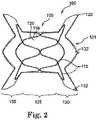
- the infundibular reducer device 100comprises a self-expandable stent portion 105 and a replacement valve portion 102 (visible in FIG. 3 ).
- the infundibular reducer device 100is preferably compressible to be inserted via catheter and expandable to fit a desired body lumen, such as the infundibulum or the right ventricular outflow tract.
- the device 100is preferably self-expandable from a first reduced diameter to a second enlarged diameter.
- the device 100is also preferably modular in expandability, meaning that different segments of the device 100 may independently expand from a first reduced diameter to a second enlarged diameter, and such different segments may rotate with respect to each other and/or cause the device 100 to shorten and lengthen.
- Such modularity of expandability of the device 100allows the device 100 to fit in an irregularly shaped implantation site (e.g., the right ventricular outflow tract).
- the stent 105is preferably formed from a plurality of wires 115 that are shaped in order for the stent portion 105 (and specifically different segments of the stent 105) to have a desired expanded configuration.
- the plurality of wires 115should allow the stent portion 105 to be compressed to a particular shape and size, and also allows the stent to regain the desired expanded configuration upon release from compression.
- the wires 115include a series of sinusoidal bends around their circumference, as shown in FIGS. 1-3 , which allow for the compression and expansion of the stent 105 with minimal force.
- the shapes of the wires 115include sinusoidal bends that resemble a sine wave with rounded apices, or the wires 115 have a zig-zag design that resembles more of a triangular wave form and with sharper apices having a smaller interior angle.
- the angles of the wires 115may depend upon the diameter of the wires 115 and the material comprising the wires 115.
- Other shapes of the wires 115, beside those shown, having, for example, different shapes, angles and numbers of apices,are also contemplated by the present invention as claimed.
- Each of the plurality of wires 115is circular in shape, without free ends.
- the ends of each of the plurality of wires 115are preferably joined using a crimped hypotube 116, as shown in FIG. 1 , that surrounds the ends and joins them.
- the ends of the wires 115may be joined using any other possible means for attachment (e.g., gluing or melting ends of wires 115 together).
- the wires 115include sinusoidal bends around their circumference.
- Each of the sinusoidal bends (or other shapes, as discussed above) of the wires 115includes an apex, and as shown, the apices of a wire 115 may each contact an apex of an adjacent wire 115 (i.e., a point-to-point configuration).
- the sinusoidal bendsmay line up, follow, or "nest” together and will not contact each other at apices (i.e., a nesting configuration).
- adjacent wires within a single devicemay have different numbers of sinusoidal bends and apices, and therefore, less than all of the apices of adjacent wires may have either a point-to-point configuration or a nesting configuration, and it is possible to have a combination of both configurations in one device.
- the different configurations of the wires 115such as the point-to-point configuration and the nesting configuration may result in different load distribution to the anatomy at the implanted site. For example, separate joints will distribute the load more than those that are connected, such as in a point-to-point configuration.
- the different configurations of the wires 115may also allow different movement of the device. For example, if a sufficient amount of the wires 125 are in a nesting configuration, the device may be able to shorten and lengthen.
- the plurality of wires 115comprise a material or materials that have shape memory characteristics, such as a nickel-titanium alloy (NitinolTM), or other similar inert biocompatible metal or combination of metals.
- the material from which the stents are madeincludes approximately 54.5 percent to 57 percent nickel, and a majority of the balance of the material comprises titanium, as such percentages are known in the field of medical devices and surgical implants (see ASTM designation: F 2063-00, for example).
- the stent portion 105is preferably formed into a desired shape and made from a framework that comprises a plurality of wires 115 made of NitinolTM.
- device 100may include a plurality of wires 115, with different wires 115 comprising different materials.
- the different materialsmay have different strengths and may contribute to modularity of the device.
- different strengths of the wires 115may result in some wires 115 expanding to a larger or a smaller diameter than other wires 115.
- one embodimentmay include a more stiff or rigid wire material for the wires surrounding the valve portion of the device, in order to stabilize the valve.
- the end portions of the devicemay include wires made of a more flexible material, in order for the end portions to conform more closely to the anatomy of the implantation site.
- the plurality of wires 115 of device 100may also have different configurations.
- the wires 115may have different numbers of sinusoidal bends or the amplitudes of such bends may differ.
- the varying configurations of the wires 115also contributes to the modularity of the device 100.
- wires 115 with sinusoidal bends that have a smaller amplitudemay be stiffer than those with bends having larger amplitudes.
- the configuration of the wires 115, as well as the number of wires 115, and the material comprising the wires 115may all be varied in order to contribute to a desired modularity of device 100 for a given application.
- the wires 115 of the stent portion 105are preferably shaped, configured and aligned such that a central lumen 101 runs through the center of the stent 105 along its length.
- a central lumen 101accommodates a replacement valve portion 102 ( FIG. 3 ), such as a bovine jugular vein, a pericardial heart valve, or other collapsible valve, for example.
- Other biological or prosthetic valvesmay also be used in the stent portion 105, having a size and shape that accommodates the patient's anatomy.
- FIG. 3illustrates the inclusion of the replacement valve portion 102, it is contemplated that any of the devices shown or described herein preferably includes such a replacement valve portion 102.
- the wires 115 of the inventionare formed in a circular shape and include a sinusoidal wave pattern. This method of manufacture is preferred because if wires fracture they generally return to their earlier configuration. Thus, if a wire is formed in a flat configuration, it will generally return to that flat configuration. The straightening of a wire in a device may result in failure of the device. Therefore, an advantage of embodiments of the invention is that because the wire 115 are preferably formed in their shaped configurations, if fracture of one wire does occur, the fracture will not result in failure of the device as a whole.
- the stent portion 105 of the device 100preferably has extremely good flexibility, dimensional stability, very smooth surfaces, a low profile when collapsed and an immunity to fatigue and corrosion.
- the length of the stent portion 105can be adjusted or designed by varying the number of wires 115 that are utilized, by varying the arrangement of wires 115, and/or by varying other features of the wires 115 and arrangement of wires 115 as discussed above.
- the working range of the stent 105 between its collapsed condition/configuration and its expanded condition/configurationcan also be adjusted by choosing or designing a certain number of curves, zig-zags or bends in each wire 115. In this way, a stent may be tailored for insertion into a particular body site to provide for the most effective implantation of the replacement valve 102 that is attached to the stent 105.
- the shape of the self-expandable stent 105is one exemplary shape, which can be described as a generally hourglass shape.
- Such an hourglass shape(which is achieved when the stent 105 is in an expanded or partially-expanded configuration) includes a middle portion 125 that is generally cylindrical in shape.
- This middle portion 125has a diameter that is preferably at least slightly smaller than the diameter of end portions 130.
- One advantage of the middle portion 125 having a smaller diameter than the end portions 130is to allow at least a portion of the middle portion 125 of the stent 105 to hold or retain a replacement valve portion (not visible) (e.g., a valved segment of bovine jugular vein) in its central lumen, when such a replacement valve portion 102 has a smaller diameter than the lumen in which the prosthetic valve 100 is to be placed.
- a replacement valve portione.g., a valved segment of bovine jugular vein
- the larger diameter of the end portions 130allows the prosthetic valve 100 to be secured in place in such a tubular organ, or a valved anatomic site, having a diameter larger than that of the replacement valve but smaller than the diameter of the end portions 130.
- the end portions 130are also shown to be flared, such that they increase in diameter from where the end portions 130 extend from the middle portion 125.
- the angle at which these flared end portions 130 extend from the middle portion 125can vary depending on the desired maximum diameter and desired length of the stent 105, along with other factors.
- crowns 132 of the device 100The areas of the ends portions 130 that result from bends in the wire 115 on the outer edge of the end portions 130 are referred to as crowns 132 of the device 100.
- the number, spacing, and amplitude of the crowns 132can vary the modularity and also the stability of the device 100 in an implanted site. The more spaced out the crowns 132 are, for example, the more flexible are the end portions 130 of the device 100.
- the inventioncontemplates many different configurations, numbers and spacings of the crowns 132.
- the crowns 132 on at least one of the end portions 130preferably comprise attachment loops 133.
- the purpose of the attachment loops 133is to attach the device 100 to a delivery system.
- the loops 133preferably do not impede blood flow through the device 100, and may be located such that the loops 133 are attached to or formed on the outer surface of the crowns 132.
- the attachment loops 133may preferably resemble belt loops, however, other shapes are contemplated.
- the attachment lops 133may be made from the same material as fabric 120, or the loops 133 may comprise suture material, for example. Other materials for the attachment loops 133 are also contemplated by the present invention, however.
- the attachment loops 133are threaded onto another component (e.g., a wire in a circular shape with free ends) of the delivery system, which allows the end portion 132 of the device 100 to be compressed and attached to the delivery system.
- a compressed configurationpreferably allows the device 100 to be inserted percutaneously.
- both end portions 130may include the attachment lops 133 on crowns 132.
- One example of a delivery system that the device 100 may be attached to by using such attachment loops 133is described in co-pending patent application filed on January 23, 2009, titled "Infundibular Reducer Device Delivery System and Related Methods," and having attorney docket number P27272.01.
- the end portions 130can be particularly articulable with respect to the middle portion 125 when the wires 115 used for the framework of the middle portion 125 and end portions 130 are not attached to each other.
- the end portions 130may be able to rotate with respect to one another and/or with respect to the middle portion 125.
- the wires 115 of the middle portion 125it would also be possible for the wires 115 of the middle portion 125 to be attached to the wires 115 of one or both end portions 130, thereby limiting movement.
- the replacement valve 102 preferably included in device 100is a pericardial heart valve or a preserved bovine jugular vein of the type described in the above-cited Bonhoeffer, et al. and Tower, et al. references. Other vessels or donor species may, however, alternatively be employed. Preferably, any collapsible valve may be used.
- Such replacement valves 102may be formed from a variety of materials including biological materials and polymers.
- Exemplary biological materialsinclude homograft, allograft or xenograft, with xenograft being common and well accepted and usually from bovine, ovine, swine or porcine pericardium, or a combination thereof.
- polymersinclude expanded TEFLONTM polymers, high density polyethylene, polyurethane, and combinations thereof.
- the replacement valve portion 102is attached to (i.e., affixed to, held by, retained by, etc.) the central lumen of the stent portion 105, and is sutured or otherwise attached within the stent 105.
- the valve portion 102may be sutured to the wires 115 and/or the fabric 120 of the stent 105.
- Other means and method for attaching the replacement valve portion 102 to the stent portion 105are also contemplated, however.
- the replacement valve portion 102is preferably positioned within the middle portion 125 of the device and in the central lumen 101.
- the stent portion 105includes one piece of fabric 120 (i.e., cloth, material, etc.) to which the wires 115 are attached or through which the wires 115 are woven.
- the fabric 120 used for the stentcan be a polyester knit, for example, or may instead be an ultra high molecular weight polyethylene (UHMWPE), cotton, or the like.
- UHMWPEultra high molecular weight polyethylene
- the fabric 120should be biocompatible and may include a number of different fabrics in different areas of the stent and/or in layers, if desired. It is also contemplated that the device 100 may include more than one piece of fabric 120.
- the fabric portion 120 of the present inventionprovides connection and support for the individual wires 115.
- the wires 115are attached to the fabric portion 120, and may be woven through the material or otherwise attached.
- a benefit to attaching the wires 115 to the fabric 120, and with such regularityis that if a single wire fails or fractures, the whole device 100 is not rendered defective or a failure.
- the wires 115preferably hold open the fabric portion 120. The movement of each wire 115 is independent in the fabric 120 and also limited by the flexibility of the wire 115 itself and by the fabric to some extent.
- the fabric 120may comprise stretchable material, such as a knit for example.
- the fabric 120may be a non-stretchable woven material, which would restrict the movement of the wires 115 more than a knit material, for example.
- the movement of the wires 115is dependent upon the choice of fabric 120 material as well as the material choice and shape of the wires 115 themselves.
- the configuration of the plurality of wires 115also affects the flexibility and movement of the stent 105.
- the wires 115are nested, as in the embodiment in FIGS. 1-3 , or aligned point-to-point, as in the comparative example shown in FIG. 4 (discussed below).
- the nested configurationallows for more flexibility of the stent 105 than the point-to-point configuration.
- the nested configurationmay also allow the device 100 to be shortened and lengthened.
- the amount of bends in the wires 115, creating the points,can also affect the flexibility and motion of the wires 115 of the stent 105.
- This nested configuration of the wires 115also aids in the retractability of the device 100 and the stability of the device 100 longitudinally.
- a point-to-point configurationin which the apices may be connected together, for example by sutures, may decrease the flexibility of the device 100. Therefore, in order to have a device 100 flexible enough to apply to the right ventricular outflow tract, which is quite irregular, it may be desired to include more nesting of wires 115 than point-to-point connections. Flexibility of the device 100 may be, for example, preferred in order to allow the device 100 to better follow the variations in the right ventricular outflow tract that occur throughout the cardiac cycle. Such flexibility in the device 100 would allow for shortening and lengthening of the device 100 without straining the device 100 throughout the cardiac cycle. However, it is contemplated that for different applications, different amounts of flexibility may be desired. The devices, therefore, may be configured with any combination of wire types, materials and configurations, in order to provide the desired amount of flexibility.
- FIG. 4shows a comparative example of the present invention.
- Infundibular reducer device 400is shown and includes a valve portion (not visible) and a stent portion 405 that comprises a plurality of wires 415 and fabric 420.
- the shape and configuration of device 400is different from that of device 100 ( FIGS. 1-3 ), including a different number, shape, and arrangement of wires 415.
- the discussion above with regard to the components of device 100also applies to the corresponding components of device 400.
- device 400also includes a middle portion 425 with a generally cylindrical shape and flared end portions 430 that include a generally angled portion and a generally straight portion that forms a cylinder with a diameter that is larger than that of the middle portion 425.
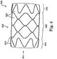
- FIG. 5shows another exemplary infundibular reducer device 600 of the present invention.
- the shape and configuration of a stent portion 605is different from that of the stent portions 105, 405 of the earlier described embodiments, including a different number, shape and arrangement of wires 615.
- the description above of the corresponding components of the other stent portionsis also applicable to the components of stent 605.
- Stent 605, however,does not include end portions 630 that have a diameter that is greater than that of the middle portion 625.
- the inner lumen(not visible) may be configured such that a valve having a smaller diameter than device 600 may be secured in the inner lumen.
- the embodiment in FIG. 5illustrates one of a plurality of configurations that are contemplated by the present invention.
- Device 700shown in FIGS. 6-8 .
- Device 700includes a stent portion 705 with a middle portion 725 and two end portions 730, 740. As shown, the end portions 730, 740 are different in device 700. End portion 730 has a larger diameter, and the wires 715 in the end portion 730 are in a nested configuration. End portion 740, on the other hand, is smaller in diameter than end portion 730 and the wires 115 are in a point-to-point configuration.
- Device 700may be arranged in an implantation site such that end portion 730 or end portion 740 is located more distal, or vice versa. Device 700 also illustrates that a plurality of different configurations of devices are contemplated by the present invention.
- the prosthetic valve or infundibular reducer device of the present inventionmay be part of a delivery system.
- a delivery systemis described in co-pending non-provisional patent application titled "Infundibular Reducer Device Delivery System and Related Methods," having docket number P27271.01 (MTI0066/US), filed on January 23, 2009.
- the infundibular reducer devices of the present inventionmay be fastened to such a delivery system using a fastening means.
- a plurality of loops 133 provided on or near the proximal end (for example, on the crowns of at least one of the end portions) of the infundibular reducer deviceis such a fastening means.
- Such loops 133may be formed from, for example, sutures or from the fabric used to form part of the stent 105.
- the attachment loops 133resemble belt loops, and do not maintain a significant profile so as to not impede blood flow.
- Other fastening means besides loops 133are also contemplated by the present invention.
- silvercan be applied to or included in the stent portion in various ways.
- silvermay be applied by using thread impregnated with silver in the stent portion.
- the silver threadcould be applied near where a replacement valve is attached to the stent portion.
- the silver threadcould help prevent excessive tissue ingrowth, which could negatively affect the function of the valve.
- Distance between the valve portion and a concentration of silverwould depend upon a margin of inhibition necessary as well as a duration needed as the device is accepted by the body. It is likely that full ingrowth would be desired for areas contacting the patient's anatomy, but inhibition of growth could be desired.
- the silvermay also be used as an antimicrobial agent, which helps prevent infection.
- a stent portion of a device of the present inventioncan include such silver impregnated thread in locations where infections are likely to develop.
- silvermay be viewed under fluoroscopy.
- the silvermay act as a marker when seeking to locate the valve under fluoroscopy for monitoring and/or subsequent location for deployment or during other procedures.
- a pattern of radiopaque markersis inclusion of a pattern of radiopaque markers.
- An examplemay be including a radiopaque marker or markers in the shape or pattern of a ring located circumferentially around the ends of the valve portion of the device.
- a ringcould be applied directly, with ink, or thread, or tape or other means.
- such a ringcould allow for easy identification and location of the valve portion of the device of the present invention under fluoroscopy for monitoring and/or subsequent deployment procedures.
- Another possibilitywould be to add radiopaque thread markers on the stent portion at various locations.
- One particular material that can be used as a radiopaque markeris a platinum strand or cable.
- Yet another possible feature of the device of the present inventionis to embed materials into the fabric used in the stent portion. These materials can be used to enhance tissue ingrowth. The purpose of tissue ingrowth is to secure the device as well as help close any paravalvular leaks.
- Some exemplary materials that can be embeddedinclude, but are not limited to, collagen, hydrophilic materials, gelatins, albumen, or other proteins. The material could be put into solution and the fabric of the stent portion could be soaked in the solution. The stent portion could then be stored in saline and post-sterilized to prevent destruction of the material in glutaraldehyde or other storage chemical sterilant.
- a further possible feature of the device of the present inventionis the addition of a felt edge on the device.
- the felt edgewould preferably be located on the crowns of at least one of the two end portions.
- the purpose of adding felt to the edgeis to control tissue ingrowth and thrombosis.
- the feltcan facilitate rapid ingrowth of tissue due to its porous nature.
- Other areas of the stentmay be made of a knit or weave where the maximum amount of ingrowth is not necessarily desired. Rapid, healthy tissue ingrowth on the edges of the stent portion, where the stent portion contacts the body, will aid in fixation of the stent to help prevent migration as well as provide strain relief from the remainder to the stent and vessel.
- a semi-permeable materialmay, for example, be desired to enhance tissue ingrowth of the endothelium into the device. In other cases, the fabric may not be desired to be permeable. It is contemplated that all levels of permeability and porosity are possible for the fabric material of the devices of the present invention.
- a hydrophobic materialsuch as Ultra High Molecular Weight Polyethylene (UHMWPE), polypropylene, etc. could be applied in a variety of ways including using thread made entirely or in part from one of these hydrophobic materials. The material would not need to be applied to all thread, however.
- hydrophobic threadcould be applied at the margin of the implanted valve portion to help prevent excessive tissue ingrowth which could affect the function of the valve. The distance from the valve and the concentration of material would depend upon the margin of inhibition necessary as well as the duration needed as the device is accepted by the body. It is likely that full ingrowth would be desired for the areas contacting the patient anatomy and inhibition of growth within the valve portion.
- the purpose of using a hydrophobic materialmay include reducing tissue ingrowth as well as reducing thrombosis.
- the wires 415 in the end portions 430can be seen to have a point to point configuration of the bends.
- the purpose of such a configurationis to keep excess fabric from being in the path of blood flow through the device 400. Particularly, this configuration is desired at the in-flow end of the device 400.
- a further optional feature of the present inventionis to add a weave or braid of structural thread to the stent portion in the area where it contacts the valve portion.
- the angle of the braid or weaveis based upon providing a firm fit for the valve portion in the stent portion, but allows for expansion at the rate of subsequent valved stents.
- the stent of the present inventionmay be completely self-expanding based upon the choice of materials and configuration of the wires.
- the stentmay be moderately self-expanding and may use a balloon to assure complete expansion.
- the wiresmay comprise MP35N, for example.
- itmay be desired to have the end portions of the device self-expandable while the middle portion, including the valve, is balloon-expandable.
- the device of the present inventionmay not be removed once the replacement valve portion of the device no longer functions, such as after a significant period of time has passed since implantation.
- the devicemay then serve as a landing zone or location where a replacement valve may be implanted or docked.
- One exemplary valve that may be implanted within the present inventive deviceis the MelodyTM Transcatheter Pulmonary Valve, made by Medtronic, Inc., Minneapolis, Minnesota, U.S.A., which is a bovine jugular vein valve. It is contemplated, however, that other similar devices may also be implanted within the present inventive device.
- the device of the present inventionpreferably includes a stent portion that is able to expand to surround the replacement device.
Landscapes
- Health & Medical Sciences (AREA)
- Engineering & Computer Science (AREA)
- Biomedical Technology (AREA)
- Cardiology (AREA)
- Veterinary Medicine (AREA)
- Heart & Thoracic Surgery (AREA)
- Vascular Medicine (AREA)
- Life Sciences & Earth Sciences (AREA)
- Animal Behavior & Ethology (AREA)
- General Health & Medical Sciences (AREA)
- Public Health (AREA)
- Transplantation (AREA)
- Oral & Maxillofacial Surgery (AREA)
- Anesthesiology (AREA)
- Hematology (AREA)
- Prostheses (AREA)
Description
- The present application claims priority to
U.S. Provisional Application No. 61/031,266, filed February 25, 2008 - This invention relates generally to the treatment of cardiac valve disease using prosthetic valves, and more particularly to replacement of malfunctioning pulmonary valves using infundibular reducer devices.
- Natural heart valves, such as aortic valves, mitral valves, pulmonary valves and tricuspid valves, often become damaged by disease in such a manner that they fail to maintain blood flow in a single direction. A malfunctioning heart valve may be stenotic (i.e., heart leaflets are closed down) or regurgitant (i.e., heart leaflets are wide open). Maintenance of blood flow in a single direction through the heart valve is important for proper flow, pressure and perfusion of blood through the body. Hence, a heart valve that does not function properly may noticeably impair the function of the heart.
- Cardiac valve prostheses are well known in the treatment of heart disease to replace malfunctioning heart valves. Heart valve replacement generally has been accomplished by major open heart surgery. This is a serious operation that requires general anesthesia, full cardiopulmonary bypass with complete cessation of cardiopulmonary activity, an extended hospitalization stay, and several more weeks to months of recuperation time. For some patients, open heart surgery is not an option because of the critical condition of the patient, advanced age, co-existing infection, or other physical limitations.
- Recently, there has been increasing interest in minimally invasive and percutaneous replacement of cardiac valves, typically by way of catheterization. In minimally invasive procedures, a catheter is used to insert a mechanical or bioprosthetic valve in a lumen of a blood vessel via percutaneous entry through a distal blood vessel. Typically, such percutaneous prosthetic valve devices comprise an expandable stent segment, a stent anchoring segment and a flow-regulation segment, such as a ball valve or a biological valve. The expandable stent portion is generally expanded using a balloon that is part of a transcatheter delivery system.
- In the specific context of pulmonary valve replacement,
U.S. Patent Application Publication Nos. 2003/0199971 A1 and2003/0199963 A1, both filed by Tower, et al. , describe replacing a pulmonary valve with a venous valvular replacement. The replacement pulmonary valve is mounted on a balloon catheter and delivered percutaneously via the vascular system to the location of the failed pulmonary valve and expanded by the balloon to compress the native valve leaflets against the right ventricular outflow tract, anchoring and sealing the replacement valve. As described in the articles:Percutaneous Insertion of the Pulmonary Valve, Bonhoeffer, et al., Journal of the American College of Cardiology 2002; 39: 1664-1669 and Transcatheter Replacement of a Bovine Valve in Pulmonary Position, Bonhoeffer, et al., Circulation 2000; 102: 813-816, the replacement pulmonary valve may be implanted to replace native pulmonary valves or prosthetic pulmonary valves located in valved conduits. Surgical procedures for percutaneous pulmonary valve implantation are described inKhambadkone et al., Percutaneous Pulmonary Valve Implantation in Humans, Circulation, 1189-1197 (Aug. 23, 2005). - Pulmonary valve replacement using venous valves is not available to all who might benefit from it due to the relatively narrow size range of available valved segments of veins, for example, with typical sizes available only up to a diameter of about 22 mm.
- Unfortunately, many patients requiring pulmonary valve replacement are adults and children who have right ventricular outflow tracts that are larger than 22 mm in diameter. This could have resulted, for example, from having previously undergone transannular patch repair of tetralogy of Fallot during infancy. There are other causes, however, for an enlarged right ventricular outflow tract. Thus, venous valvular replacements, having an upper limit of 22 mm on their diameters, cannot typically be securely implanted within these patients.
WO 2007/071436 describes a double-stent valve for valve replacement. - Thus, there is a continuing need to improve upon the devices available for heart valve replacement, in particular those including venous valve replacements and pericardial valve replacements, and even more particularly those that may be placed in patients with irregular right ventricular outflow tracts (e.g., right ventricular outflow tracts that are larger than 22 mm in diameter, or irregular in shape).
- The present invention is directed toward prosthetic heart valve assemblies as defined in claim 1. In particular, the present invention provides infundibular reducer devices used for replacing a malfunctioning heart valve, and in particular, a pulmonary heart valve. The infundibular reducer devices may be delivered through percutaneous transcatheter implantation to an anatomic site within the heart. The devices are at least partially self-expandable, and have modularity, such that segments of the devices are independently expandable with respect to other segments of the devices. Preferably, the infundibular reducer devices include a pericardial heart valve or a valved segment of bovine jugular vein, for example, and are implanted in the right ventricular outflow tract, for example. In addition, however, it is contemplated that the present inventive devices may include other collapsible valves and may be implanted in other anatomical sites in the body.
- A benefit of some embodiments of the present invention is that the devices may be delivered through a catheter to the desired anatomic site and may expand without a need for a n to expand the devices. Delivery of devices without a balloon minimizes the bulkiness of the delivery system, which can allow for easier insertion and removal of the devices.
- Another benefit of the present invention is that modularity of the devices allows different segments of the devices to expand and move independently. Thus, the devices are able to conform more closely to an irregular implanted site. Certain segments of the devices may rotate with respect to other segments, and the devices may shorten and lengthen. The devices are also able to move within the implanted site during the cardiac cycle, and still conform to the implanted site. As a result, the devices are more effective.
- Another benefit of the devices is that the devices may be collapsed and repositioned after partial deployment or partial expansion. This is beneficial if it is determined during early stages of delivery of one of the devices that the device is not being placed correctly. The device may then be re-compressed and moved to a correct location.
- Yet another benefit of the devise of the present invention is that the devices are easily explantable. The stent portion may be peeled from the wall of the implanted site, collapsed, and the valve and stent may then be removed from the body.
- A further benefit of the present invention is that drastic failure of the devices due to fracture of one wire or a few wires is eliminated. Since the stent portions of the devices are comprised of a plurality of wires that are independently connected in a plurality of locations to the fabric frame, fracture of one wire or a few wires does not cause the whole device to fail.
- A still further benefit of some embodiments of the invention is that the devices may include features that allow the devices to be located using fluoroscopy, for example. Fluoroscopy may be helpful in placement of the devices as well as for later identification purposes.
- An additional benefit of some embodiments of the devices is that the devices may include materials that are antimicrobial, prevent thrombosis, and either increase or reduce tissue ingrowth. Such materials allow the devices to be better secured in a vessel, and decrease the chance of rejection of the devices.
- Another benefit of the present invention is that the stent portion may later serve as a landing zone or site for implantation of a later-needed prosthetic valve. Another valve may be delivered percutaneously to the inner lumen of the device that is already implanted.
- A first aspect of the present invention is a prosthetic valve assembly. One embodiment comprises: a radially self-expandable stent configured to expand to bear against a wall of a native body lumen; and an implantable prosthetic valve, having a diameter, the valve being mounted inside the stent; wherein the diameter of the stent is greater than the diameter of the prosthetic valve. The stent may comprise a plurality of wires. The plurality of wires may comprise a material having shape memory, or the plurality of wires may comprise a plurality of different materials. The plurality of wires are circular in shape and include a plurality of sinusoidal bends. The sinusoidal bends in the wires may have different sizes. At least some of the plurality of wires are in a nested configuration. At least some of the plurality of wires are in a point-to-point configuration. The stent comprises a middle portion having a smaller diameter than at end portions thereof, and the valve is mounted in the middle portion. The stent may comprise a middle portion having a diameter and end portions thereof may have tapered diameters in directions toward the middle portion, and the valve may be mounted in the middle portion. The middle portion may be cylindrical in shape. The stent may comprise a plurality of wires attached to at least one piece of fabric. The middle portion and each end portion articulate with respect to each other.
- A second embodiment of the invention is a prosthetic valve assembly comprising: a radially self-expandable stent comprising a middle portion having a smaller diameter than end portions thereof, with the end portions configured to expand to bear against a wall of a native body lumen; and an implantable prosthetic valve mounted inside the middle portion of the stent. The stent comprises a plurality of wires. The plurality of wires may comprise a plurality of different materials. The plurality of wires are circular in shape and include a plurality of bends. The bends in the wires are sinusoidal in shape. The plurality of wires may comprise a material having shape memory. The end portions may have tapered diameters in directions toward the middle portion. The middle portion may be cylindrical in shape. The stent may comprise a plurality of wires attached to at least one piece of fabric. The middle portion and each end portion articulate with respect to each other. At least some of the plurality of wires are in a nested configuration. At least some of the plurality of wires are in a point-to-point configuration.
- A third embodiment of the present invention is a prosthetic valve assembly comprising: a radially self-expandable stent configured to expand to bear against a wall of a native body lumen, the stent comprising: a plurality of wires; and at least one piece of fabric to which the plurality of wires are attached; and an implantable prosthetic valve mounted inside the stent; wherein the plurality of wires of the stent are individually expandable and compressible providing the assembly with modularity. The plurality of wires comprise circular wires having a plurality of bends around the circumference of the circular wires as further described in the claims. The plurality of wires are in a nested configuration or a point-to-point configuration or a combination thereof, within the scope of claim 1. The plurality of wires may comprise a material having shape memory.
- The present invention will be further explained with reference to the appended Figures, wherein like structure is referred to by like numerals throughout the several views, and wherein:
FIG. 1 is a perspective view of an infundibular reducer device, in accordance with the present invention;FIG. 2 is a side view of the infundibular reducer device ofFIG. 1 ;FIG. 3 is an end view of the infundibular device ofFIGS. 1 and2 ;FIG. 4 is a side view of an infundibular reducer device, in accordance with a comparative example;FIG. 5 is a side view of an infundibular reducer device, in accordance with the present invention;FIG. 6 is a perspective view of an infundibular device, in accordance with the present invention;FIG. 7 is a side view of the infundibular device ofFIG. 6 ; andFIG. 8 is an end view of the infundibular device ofFIGS. 6 and 7 .- With reference to the accompanying figures, wherein like components are labeled with like numerals throughout the figures, illustrative infundibular reducer and related devices are disclosed, taught and suggested by the multiple embodiments. Although the devices are called "infundibular reducer" devices, the devices may be used in anatomic locations other than the infundibulum, such as the right ventricular outflow tract and other locations in the heart. In particular, the devices allow for prosthetic heart valves to be implanted in the right ventricular outflow tract or the infundibulum. The purpose of such devices is to allow replacement valves, such as pericardial heart valves, for example, having a smaller diameter than the diameter of the implanted site (e.g., the right ventricular outflow tract) to be implanted. However, the devices generally disclosed and shown may be used for other purposes as well.
- The devices disclosed are beneficially configured such that the devices fit well in irregularly-shaped anatomy. The infundibular reducer devices of the present invention are preferably at least partially self-expandable. In addition, the devices are modular, which means that different segments of the devices are somewhat independent in their ability to expand and move. Thus, the devices are able to conform more closely to an irregularly shaped implant site. In addition, the modularity of the devices allows different segments of the devices to move with respect to one another in order to accommodate the movement of different segments of the implant site during a cardiac cycle, for example. The feature of the devices that allows for the modularity is the plurality of wires that comprise the device. These wires are preferably independently connected to one piece of fabric, for example. The configuration of and the material that comprises each of the plurality of wires may vary in order to provide additional modularity of the devices. As a result of the modularity, in particular, some segments of the devices may expand to greater diameters than other segments. Segments may rotate with respect to other segments. Also, the devices may be able to shorten and lengthen. Thus, the modularity also allows the devices to better fit in an irregularly shaped implant site and move within the site during a cardiac cycle, for example. Thus, the devices are more stable in the implant site, and are more effective. The better contact that the device has with the wall of the implant site, the more stable the device is in the site, which prevents paravalvular leaks around the device.
- The embodiments of the present invention described below are not intended to be exhaustive or to limit the invention to the precise forms disclosed in the following detailed description. Rather the embodiments are chosen and described so that others skilled in the art may appreciate and understand the principles and practices of the present invention which are defined by the claims.
- Referring now to
FIGS. 1-3 , aninfundibular reducer device 100, in accordance with the present invention, is shown. Theinfundibular reducer device 100 comprises a self-expandable stent portion 105 and a replacement valve portion 102 (visible inFIG. 3 ). - The
infundibular reducer device 100 is preferably compressible to be inserted via catheter and expandable to fit a desired body lumen, such as the infundibulum or the right ventricular outflow tract. Thedevice 100 is preferably self-expandable from a first reduced diameter to a second enlarged diameter. Thedevice 100 is also preferably modular in expandability, meaning that different segments of thedevice 100 may independently expand from a first reduced diameter to a second enlarged diameter, and such different segments may rotate with respect to each other and/or cause thedevice 100 to shorten and lengthen. Such modularity of expandability of thedevice 100 allows thedevice 100 to fit in an irregularly shaped implantation site (e.g., the right ventricular outflow tract). - In order to be self-expandable and modular, the
stent 105 is preferably formed from a plurality ofwires 115 that are shaped in order for the stent portion 105 (and specifically different segments of the stent 105) to have a desired expanded configuration. The plurality ofwires 115 should allow thestent portion 105 to be compressed to a particular shape and size, and also allows the stent to regain the desired expanded configuration upon release from compression. Thewires 115 include a series of sinusoidal bends around their circumference, as shown inFIGS. 1-3 , which allow for the compression and expansion of thestent 105 with minimal force. The shapes of thewires 115 include sinusoidal bends that resemble a sine wave with rounded apices, or thewires 115 have a zig-zag design that resembles more of a triangular wave form and with sharper apices having a smaller interior angle. The angles of thewires 115 may depend upon the diameter of thewires 115 and the material comprising thewires 115. Other shapes of thewires 115, beside those shown, having, for example, different shapes, angles and numbers of apices, are also contemplated by the present invention as claimed. - Each of the plurality of
wires 115 is circular in shape, without free ends. The ends of each of the plurality ofwires 115 are preferably joined using acrimped hypotube 116, as shown inFIG. 1 , that surrounds the ends and joins them. However, it is contemplated that the ends of thewires 115 may be joined using any other possible means for attachment (e.g., gluing or melting ends ofwires 115 together). - The
wires 115 include sinusoidal bends around their circumference. Each of the sinusoidal bends (or other shapes, as discussed above) of thewires 115 includes an apex, and as shown, the apices of awire 115 may each contact an apex of an adjacent wire 115 (i.e., a point-to-point configuration). Alternatively, the sinusoidal bends may line up, follow, or "nest" together and will not contact each other at apices (i.e., a nesting configuration). It is also contemplated, however, that adjacent wires within a single device may have different numbers of sinusoidal bends and apices, and therefore, less than all of the apices of adjacent wires may have either a point-to-point configuration or a nesting configuration, and it is possible to have a combination of both configurations in one device. The different configurations of thewires 115, such as the point-to-point configuration and the nesting configuration may result in different load distribution to the anatomy at the implanted site. For example, separate joints will distribute the load more than those that are connected, such as in a point-to-point configuration. The different configurations of thewires 115 may also allow different movement of the device. For example, if a sufficient amount of thewires 125 are in a nesting configuration, the device may be able to shorten and lengthen. - Preferably, the plurality of
wires 115 comprise a material or materials that have shape memory characteristics, such as a nickel-titanium alloy (Nitinol™), or other similar inert biocompatible metal or combination of metals. In one embodiment, the material from which the stents are made includes approximately 54.5 percent to 57 percent nickel, and a majority of the balance of the material comprises titanium, as such percentages are known in the field of medical devices and surgical implants (see ASTM designation: F 2063-00, for example). In theprosthetic valve 100 shown, thestent portion 105 is preferably formed into a desired shape and made from a framework that comprises a plurality ofwires 115 made of Nitinol™. - It is possible for
device 100 to include a plurality ofwires 115, withdifferent wires 115 comprising different materials. In particular, the different materials may have different strengths and may contribute to modularity of the device. For example, different strengths of thewires 115 may result in somewires 115 expanding to a larger or a smaller diameter thanother wires 115. For example, one embodiment may include a more stiff or rigid wire material for the wires surrounding the valve portion of the device, in order to stabilize the valve. Meanwhile, the end portions of the device may include wires made of a more flexible material, in order for the end portions to conform more closely to the anatomy of the implantation site. - The plurality of
wires 115 ofdevice 100 may also have different configurations. For example, thewires 115 may have different numbers of sinusoidal bends or the amplitudes of such bends may differ. The varying configurations of thewires 115 also contributes to the modularity of thedevice 100. For example,wires 115 with sinusoidal bends that have a smaller amplitude may be stiffer than those with bends having larger amplitudes. Thus, the configuration of thewires 115, as well as the number ofwires 115, and the material comprising thewires 115 may all be varied in order to contribute to a desired modularity ofdevice 100 for a given application. - The
wires 115 of thestent portion 105 are preferably shaped, configured and aligned such that acentral lumen 101 runs through the center of thestent 105 along its length. Such acentral lumen 101 accommodates a replacement valve portion 102 (FIG. 3 ), such as a bovine jugular vein, a pericardial heart valve, or other collapsible valve, for example. Other biological or prosthetic valves may also be used in thestent portion 105, having a size and shape that accommodates the patient's anatomy. Although onlyFIG. 3 illustrates the inclusion of thereplacement valve portion 102, it is contemplated that any of the devices shown or described herein preferably includes such areplacement valve portion 102. - The
wires 115 of the invention are formed in a circular shape and include a sinusoidal wave pattern. This method of manufacture is preferred because if wires fracture they generally return to their earlier configuration. Thus, if a wire is formed in a flat configuration, it will generally return to that flat configuration. The straightening of a wire in a device may result in failure of the device. Therefore, an advantage of embodiments of the invention is that because thewire 115 are preferably formed in their shaped configurations, if fracture of one wire does occur, the fracture will not result in failure of the device as a whole. - The
stent portion 105 of thedevice 100, of the construction and configuration as herein described, preferably has extremely good flexibility, dimensional stability, very smooth surfaces, a low profile when collapsed and an immunity to fatigue and corrosion. The length of thestent portion 105 can be adjusted or designed by varying the number ofwires 115 that are utilized, by varying the arrangement ofwires 115, and/or by varying other features of thewires 115 and arrangement ofwires 115 as discussed above. The working range of thestent 105 between its collapsed condition/configuration and its expanded condition/configuration can also be adjusted by choosing or designing a certain number of curves, zig-zags or bends in eachwire 115. In this way, a stent may be tailored for insertion into a particular body site to provide for the most effective implantation of thereplacement valve 102 that is attached to thestent 105. - The shape of the self-
expandable stent 105, as shown inFIG. 2 is one exemplary shape, which can be described as a generally hourglass shape. Such an hourglass shape (which is achieved when thestent 105 is in an expanded or partially-expanded configuration) includes amiddle portion 125 that is generally cylindrical in shape. Thismiddle portion 125 has a diameter that is preferably at least slightly smaller than the diameter ofend portions 130. One advantage of themiddle portion 125 having a smaller diameter than theend portions 130 is to allow at least a portion of themiddle portion 125 of thestent 105 to hold or retain a replacement valve portion (not visible) (e.g., a valved segment of bovine jugular vein) in its central lumen, when such areplacement valve portion 102 has a smaller diameter than the lumen in which theprosthetic valve 100 is to be placed. The larger diameter of theend portions 130 allows theprosthetic valve 100 to be secured in place in such a tubular organ, or a valved anatomic site, having a diameter larger than that of the replacement valve but smaller than the diameter of theend portions 130. Theend portions 130 are also shown to be flared, such that they increase in diameter from where theend portions 130 extend from themiddle portion 125. The angle at which these flaredend portions 130 extend from themiddle portion 125 can vary depending on the desired maximum diameter and desired length of thestent 105, along with other factors. - It is also possible to vary the number, configuration and material of the
wires 115 in themiddle portion 125 in order to allow thestent 105 to be more rigid in that area, for example. Increased rigidity in themiddle portion 125 may assist in better retaining and supporting areplacement valve 102 in thedevice 100. - The areas of the
ends portions 130 that result from bends in thewire 115 on the outer edge of theend portions 130 are referred to ascrowns 132 of thedevice 100. The number, spacing, and amplitude of thecrowns 132 can vary the modularity and also the stability of thedevice 100 in an implanted site. The more spaced out thecrowns 132 are, for example, the more flexible are theend portions 130 of thedevice 100. The invention contemplates many different configurations, numbers and spacings of thecrowns 132. - The
crowns 132 on at least one of theend portions 130 preferably compriseattachment loops 133. The purpose of theattachment loops 133 is to attach thedevice 100 to a delivery system. Theloops 133 preferably do not impede blood flow through thedevice 100, and may be located such that theloops 133 are attached to or formed on the outer surface of thecrowns 132. Theattachment loops 133 may preferably resemble belt loops, however, other shapes are contemplated. The attachment lops 133 may be made from the same material asfabric 120, or theloops 133 may comprise suture material, for example. Other materials for theattachment loops 133 are also contemplated by the present invention, however. - In particular, the
attachment loops 133 are threaded onto another component (e.g., a wire in a circular shape with free ends) of the delivery system, which allows theend portion 132 of thedevice 100 to be compressed and attached to the delivery system. Such a compressed configuration preferably allows thedevice 100 to be inserted percutaneously. Alternatively, both endportions 130 may include the attachment lops 133 oncrowns 132. One example of a delivery system that thedevice 100 may be attached to by usingsuch attachment loops 133 is described in co-pending patent application filed on January 23, 2009, titled "Infundibular Reducer Device Delivery System and Related Methods," and having attorney docket number P27272.01. - In the
device 100 shown in the Figures, theend portions 130 can be particularly articulable with respect to themiddle portion 125 when thewires 115 used for the framework of themiddle portion 125 and endportions 130 are not attached to each other. For example, theend portions 130 may be able to rotate with respect to one another and/or with respect to themiddle portion 125. However, it would also be possible for thewires 115 of themiddle portion 125 to be attached to thewires 115 of one or bothend portions 130, thereby limiting movement. - The
replacement valve 102 preferably included indevice 100 is a pericardial heart valve or a preserved bovine jugular vein of the type described in the above-cited Bonhoeffer, et al. and Tower, et al. references. Other vessels or donor species may, however, alternatively be employed. Preferably, any collapsible valve may be used. - Such replacement valves 102 (example seen in
FIG. 3 ) may be formed from a variety of materials including biological materials and polymers. Exemplary biological materials include homograft, allograft or xenograft, with xenograft being common and well accepted and usually from bovine, ovine, swine or porcine pericardium, or a combination thereof. For example, polymers include expanded TEFLON™ polymers, high density polyethylene, polyurethane, and combinations thereof. Some examples ofreplacement valves 102 used in the present invention are described inU.S. Patent Nos. 6,719,789 and5,480,424, issued to Cox . - The
replacement valve portion 102 is attached to (i.e., affixed to, held by, retained by, etc.) the central lumen of thestent portion 105, and is sutured or otherwise attached within thestent 105. Thevalve portion 102 may be sutured to thewires 115 and/or thefabric 120 of thestent 105. Other means and method for attaching thereplacement valve portion 102 to thestent portion 105 are also contemplated, however. As discussed above, thereplacement valve portion 102 is preferably positioned within themiddle portion 125 of the device and in thecentral lumen 101. - Also, in
FIG. 1 , thestent portion 105 includes one piece of fabric 120 (i.e., cloth, material, etc.) to which thewires 115 are attached or through which thewires 115 are woven. Thefabric 120 used for the stent can be a polyester knit, for example, or may instead be an ultra high molecular weight polyethylene (UHMWPE), cotton, or the like. Thefabric 120 should be biocompatible and may include a number of different fabrics in different areas of the stent and/or in layers, if desired. It is also contemplated that thedevice 100 may include more than one piece offabric 120. - The
fabric portion 120 of the present invention provides connection and support for theindividual wires 115. Thewires 115 are attached to thefabric portion 120, and may be woven through the material or otherwise attached. A benefit to attaching thewires 115 to thefabric 120, and with such regularity (e.g., every 1 to 2 mm along the wires 115), is that if a single wire fails or fractures, thewhole device 100 is not rendered defective or a failure. Thewires 115 preferably hold open thefabric portion 120. The movement of eachwire 115 is independent in thefabric 120 and also limited by the flexibility of thewire 115 itself and by the fabric to some extent. Thefabric 120 may comprise stretchable material, such as a knit for example. Alternatively, thefabric 120 may be a non-stretchable woven material, which would restrict the movement of thewires 115 more than a knit material, for example. Thus, the movement of thewires 115 is dependent upon the choice offabric 120 material as well as the material choice and shape of thewires 115 themselves. - The configuration of the plurality of
wires 115 also affects the flexibility and movement of thestent 105. For example, thewires 115 are nested, as in the embodiment inFIGS. 1-3 , or aligned point-to-point, as in the comparative example shown inFIG. 4 (discussed below). The nested configuration allows for more flexibility of thestent 105 than the point-to-point configuration. The nested configuration may also allow thedevice 100 to be shortened and lengthened. The amount of bends in thewires 115, creating the points, can also affect the flexibility and motion of thewires 115 of thestent 105. This nested configuration of thewires 115 also aids in the retractability of thedevice 100 and the stability of thedevice 100 longitudinally. - A point-to-point configuration, in which the apices may be connected together, for example by sutures, may decrease the flexibility of the
device 100. Therefore, in order to have adevice 100 flexible enough to apply to the right ventricular outflow tract, which is quite irregular, it may be desired to include more nesting ofwires 115 than point-to-point connections. Flexibility of thedevice 100 may be, for example, preferred in order to allow thedevice 100 to better follow the variations in the right ventricular outflow tract that occur throughout the cardiac cycle. Such flexibility in thedevice 100 would allow for shortening and lengthening of thedevice 100 without straining thedevice 100 throughout the cardiac cycle. However, it is contemplated that for different applications, different amounts of flexibility may be desired. The devices, therefore, may be configured with any combination of wire types, materials and configurations, in order to provide the desired amount of flexibility. FIG. 4 shows a comparative example of the present invention.Infundibular reducer device 400 is shown and includes a valve portion (not visible) and astent portion 405 that comprises a plurality ofwires 415 andfabric 420. The shape and configuration ofdevice 400 is different from that of device 100 (FIGS. 1-3 ), including a different number, shape, and arrangement ofwires 415. The discussion above with regard to the components ofdevice 100, however, also applies to the corresponding components ofdevice 400. For example,device 400 also includes amiddle portion 425 with a generally cylindrical shape and flaredend portions 430 that include a generally angled portion and a generally straight portion that forms a cylinder with a diameter that is larger than that of themiddle portion 425.FIG. 5 shows another exemplaryinfundibular reducer device 600 of the present invention. Again, the shape and configuration of astent portion 605 is different from that of thestent portions wires 615. However, the description above of the corresponding components of the other stent portions is also applicable to the components ofstent 605.Stent 605, however, does not includeend portions 630 that have a diameter that is greater than that of themiddle portion 625. In this embodiment, the inner lumen (not visible) may be configured such that a valve having a smaller diameter thandevice 600 may be secured in the inner lumen. The embodiment inFIG. 5 illustrates one of a plurality of configurations that are contemplated by the present invention.- Another preferred embodiment of the present invention is
device 700 shown inFIGS. 6-8 .Device 700 includes astent portion 705 with amiddle portion 725 and twoend portions end portions device 700.End portion 730 has a larger diameter, and thewires 715 in theend portion 730 are in a nested configuration.End portion 740, on the other hand, is smaller in diameter thanend portion 730 and thewires 115 are in a point-to-point configuration.Device 700 may be arranged in an implantation site such thatend portion 730 orend portion 740 is located more distal, or vice versa.Device 700 also illustrates that a plurality of different configurations of devices are contemplated by the present invention. - The prosthetic valve or infundibular reducer device of the present invention may be part of a delivery system. One exemplary such delivery system is described in co-pending non-provisional patent application titled "Infundibular Reducer Device Delivery System and Related Methods," having docket number P27271.01 (MTI0066/US), filed on January 23, 2009. The infundibular reducer devices of the present invention may be fastened to such a delivery system using a fastening means. A plurality of
loops 133 provided on or near the proximal end (for example, on the crowns of at least one of the end portions) of the infundibular reducer device is such a fastening means.Such loops 133 may be formed from, for example, sutures or from the fabric used to form part of thestent 105. Preferably, theattachment loops 133 resemble belt loops, and do not maintain a significant profile so as to not impede blood flow. Other fastening means besidesloops 133 are also contemplated by the present invention. - Below is a description of additional or optional features that can be included with any of the infundibular reducer devices described above and or other stent-based devices that can be used in the same or different parts of the body.
- Another feature that can be included in the device of the present invention is to include silver in the stent portion. Silver can be applied to or included in the stent portion in various ways. For example, silver may be applied by using thread impregnated with silver in the stent portion. The silver thread could be applied near where a replacement valve is attached to the stent portion. The silver thread could help prevent excessive tissue ingrowth, which could negatively affect the function of the valve. Distance between the valve portion and a concentration of silver would depend upon a margin of inhibition necessary as well as a duration needed as the device is accepted by the body. It is likely that full ingrowth would be desired for areas contacting the patient's anatomy, but inhibition of growth could be desired. The silver may also be used as an antimicrobial agent, which helps prevent infection. Thus, a stent portion of a device of the present invention can include such silver impregnated thread in locations where infections are likely to develop.
- Another purpose for using silver thread is that silver may be viewed under fluoroscopy. Thus, the silver may act as a marker when seeking to locate the valve under fluoroscopy for monitoring and/or subsequent location for deployment or during other procedures.
- Yet another possible feature of the device of the present invention is inclusion of a pattern of radiopaque markers. An example may be including a radiopaque marker or markers in the shape or pattern of a ring located circumferentially around the ends of the valve portion of the device. Such a ring could be applied directly, with ink, or thread, or tape or other means. In particular, such a ring could allow for easy identification and location of the valve portion of the device of the present invention under fluoroscopy for monitoring and/or subsequent deployment procedures. It is also possible to have a plurality of bands or radiopaque material generally equally spaced along the length of the valve portion. The purpose of the markers would be to locate the valve, especially during subsequent deployment of future prosthetic valves. Another possibility would be to add radiopaque thread markers on the stent portion at various locations. One particular material that can be used as a radiopaque marker is a platinum strand or cable.
- Yet another possible feature of the device of the present invention is to embed materials into the fabric used in the stent portion. These materials can be used to enhance tissue ingrowth. The purpose of tissue ingrowth is to secure the device as well as help close any paravalvular leaks. Some exemplary materials that can be embedded include, but are not limited to, collagen, hydrophilic materials, gelatins, albumen, or other proteins. The material could be put into solution and the fabric of the stent portion could be soaked in the solution. The stent portion could then be stored in saline and post-sterilized to prevent destruction of the material in glutaraldehyde or other storage chemical sterilant.
- A further possible feature of the device of the present invention is the addition of a felt edge on the device. The felt edge would preferably be located on the crowns of at least one of the two end portions. The purpose of adding felt to the edge is to control tissue ingrowth and thrombosis. The felt can facilitate rapid ingrowth of tissue due to its porous nature. Other areas of the stent may be made of a knit or weave where the maximum amount of ingrowth is not necessarily desired. Rapid, healthy tissue ingrowth on the edges of the stent portion, where the stent portion contacts the body, will aid in fixation of the stent to help prevent migration as well as provide strain relief from the remainder to the stent and vessel.
- Further embodiments of the present invention are possible by varying the permeability or porosity of the fabric used in the device. A semi-permeable material may, for example, be desired to enhance tissue ingrowth of the endothelium into the device. In other cases, the fabric may not be desired to be permeable. It is contemplated that all levels of permeability and porosity are possible for the fabric material of the devices of the present invention.
- Another possible feature of the present inventive device is adding a hydrophobic material to the stent portion. A hydrophobic material, such as Ultra High Molecular Weight Polyethylene (UHMWPE), polypropylene, etc. could be applied in a variety of ways including using thread made entirely or in part from one of these hydrophobic materials. The material would not need to be applied to all thread, however. For example, hydrophobic thread could be applied at the margin of the implanted valve portion to help prevent excessive tissue ingrowth which could affect the function of the valve. The distance from the valve and the concentration of material would depend upon the margin of inhibition necessary as well as the duration needed as the device is accepted by the body. It is likely that full ingrowth would be desired for the areas contacting the patient anatomy and inhibition of growth within the valve portion. The purpose of using a hydrophobic material may include reducing tissue ingrowth as well as reducing thrombosis.
- Another optional feature of the present invention can be seen in the comparative example shown in
FIG.4 . Thewires 415 in theend portions 430 can be seen to have a point to point configuration of the bends. The purpose of such a configuration is to keep excess fabric from being in the path of blood flow through thedevice 400. Particularly, this configuration is desired at the in-flow end of thedevice 400. - A further optional feature of the present invention is to add a weave or braid of structural thread to the stent portion in the area where it contacts the valve portion. The angle of the braid or weave is based upon providing a firm fit for the valve portion in the stent portion, but allows for expansion at the rate of subsequent valved stents.
- In some embodiments, the stent of the present invention may be completely self-expanding based upon the choice of materials and configuration of the wires. In other embodiments, the stent may be moderately self-expanding and may use a balloon to assure complete expansion. In such an embodiment, the wires may comprise MP35N, for example. For example, it may be desired to have the end portions of the device self-expandable while the middle portion, including the valve, is balloon-expandable.
- It is contemplated that the device of the present invention may not be removed once the replacement valve portion of the device no longer functions, such as after a significant period of time has passed since implantation. The device may then serve as a landing zone or location where a replacement valve may be implanted or docked. One exemplary valve that may be implanted within the present inventive device is the Melody™ Transcatheter Pulmonary Valve, made by Medtronic, Inc., Minneapolis, Minnesota, U.S.A., which is a bovine jugular vein valve. It is contemplated, however, that other similar devices may also be implanted within the present inventive device. The device of the present invention preferably includes a stent portion that is able to expand to surround the replacement device.
- The present invention has now been described with reference to several embodiments thereof. The foregoing detailed description and examples have been given for clarity of understanding only. No unnecessary limitations are to be understood therefrom. It will be apparent to those skilled in the art that many changes can be made in the embodiments described without departing from the scope of the invention. Thus, the scope of the present invention should not be limited to the structures described herein, but only by the structures described by the language of the claims and the equivalents of those structures.
Claims (9)
- A prosthetic heart valve assembly (100) configured for implantation to an anatomic site within the heart, and comprising:a radially self-expandable stent (105) configured to expand to bear against a wall of a native body lumen; andan implantable prosthetic valve (102), having a diameter, the valve (102) being mounted inside the stent (105);wherein the diameter of the stent (105) is greater than the diameter of the prosthetic valve (102), andcharacterized in that the stent (105) comprises a plurality of wires (115) which are circular in shape and include a plurality of sinusoidal bends, and
wherein the stent (105) comprises a middle portion (125) having a smaller diameter than at end portions (130) thereof, and the valve (102) is mounted in the middle portion (125),
wherein at least one of the end portions (130) comprises attachment loops (133) for attachment of the prosthetic heart valve assembly to a delivery system, and
wherein at least some of the plurality of wires (115) arc in a nested configuration. - The prosthetic valve assembly of claim 1, wherein the plurality of wires (115) comprise a material having shape memory.
- The prosthetic valve assembly of claim 1, wherein the plurality of wires (115) comprise a plurality of different materials.
- The prosthetic valve assembly of claim 1, wherein the sinusoidal bends in the wires (115) have different sizes.
- The prosthetic valve assembly of claim 1, wherein at least some of the plurality of wires (115) are in a point-to-point configuration.
- The prosthetic valve assembly of claim 1, wherein the middle portion (125) has a diameter and the end portions (130) have tapered diameters in directions toward the middle portion (125).
- The prosthetic valve assembly of claim 6, wherein the middle portion (125) is cylindrical in shape.
- The prosthetic valve assembly of claim 1, wherein the stent (105) comprises a plurality of wires (115) attached to at least one piece of fabric (120).
- The prosthetic valve assembly of claim 1, wherein the middle portion (125) and each end portion (130) articulate with respect to each other.
Applications Claiming Priority (2)
| Application Number | Priority Date | Filing Date | Title |
|---|---|---|---|
| US3126608P | 2008-02-25 | 2008-02-25 | |
| PCT/US2009/034949WO2009108615A1 (en) | 2008-02-25 | 2009-02-24 | Infundibular reducer devices |
Publications (3)
| Publication Number | Publication Date |
|---|---|
| EP2257242A1 EP2257242A1 (en) | 2010-12-08 |
| EP2257242B1 EP2257242B1 (en) | 2013-02-20 |
| EP2257242B2true EP2257242B2 (en) | 2019-09-04 |
Family
ID=40512153
Family Applications (1)
| Application Number | Title | Priority Date | Filing Date |
|---|---|---|---|
| EP09714661.7AActiveEP2257242B2 (en) | 2008-02-25 | 2009-02-24 | Infundibular reducer devices |
Country Status (9)
| Country | Link |
|---|---|
| US (1) | US8801776B2 (en) |
| EP (1) | EP2257242B2 (en) |
| JP (2) | JP2011512948A (en) |
| KR (1) | KR101616138B1 (en) |
| CN (1) | CN101951858B (en) |
| AU (1) | AU2009219415B2 (en) |
| CA (1) | CA2715448C (en) |
| MX (1) | MX2010009289A (en) |
| WO (1) | WO2009108615A1 (en) |
Families Citing this family (303)
| Publication number | Priority date | Publication date | Assignee | Title |
|---|---|---|---|---|
| CA2462509A1 (en)* | 2001-10-04 | 2003-04-10 | Neovasc Medical Ltd. | Flow reducing implant |
| DE102005003632A1 (en) | 2005-01-20 | 2006-08-17 | Fraunhofer-Gesellschaft zur Förderung der angewandten Forschung e.V. | Catheter for the transvascular implantation of heart valve prostheses |
| US7914569B2 (en) | 2005-05-13 | 2011-03-29 | Medtronics Corevalve Llc | Heart valve prosthesis and methods of manufacture and use |
| WO2007072469A2 (en)* | 2005-12-23 | 2007-06-28 | Vysera Biomedical Limited | A medical device suitable for treating reflux from a stomach to an oesophagus |
| US11304800B2 (en) | 2006-09-19 | 2022-04-19 | Medtronic Ventor Technologies Ltd. | Sinus-engaging valve fixation member |
| US8834564B2 (en) | 2006-09-19 | 2014-09-16 | Medtronic, Inc. | Sinus-engaging valve fixation member |
| US8876894B2 (en) | 2006-09-19 | 2014-11-04 | Medtronic Ventor Technologies Ltd. | Leaflet-sensitive valve fixation member |
| US7896915B2 (en) | 2007-04-13 | 2011-03-01 | Jenavalve Technology, Inc. | Medical device for treating a heart valve insufficiency |
| US8728154B2 (en) | 2007-08-24 | 2014-05-20 | St. Jude Medical, Inc. | Prosthetic aortic heart valves |
| EP3443938B1 (en) | 2007-09-26 | 2024-01-24 | St. Jude Medical, LLC | Collapsible prosthetic heart valves |
| US9532868B2 (en) | 2007-09-28 | 2017-01-03 | St. Jude Medical, Inc. | Collapsible-expandable prosthetic heart valves with structures for clamping native tissue |
| WO2009045334A1 (en) | 2007-09-28 | 2009-04-09 | St. Jude Medical, Inc. | Collapsible/expandable prosthetic heart valves with native calcified leaflet retention features |
| CA2714062A1 (en) | 2008-01-24 | 2009-07-30 | Medtronic, Inc. | Stents for prosthetic heart valves |
| US8157853B2 (en) | 2008-01-24 | 2012-04-17 | Medtronic, Inc. | Delivery systems and methods of implantation for prosthetic heart valves |
| BR112012021347A2 (en) | 2008-02-26 | 2019-09-24 | Jenavalve Tecnology Inc | stent for positioning and anchoring a valve prosthesis at an implantation site in a patient's heart |
| US9044318B2 (en) | 2008-02-26 | 2015-06-02 | Jenavalve Technology Gmbh | Stent for the positioning and anchoring of a valvular prosthesis |
| WO2009108355A1 (en) | 2008-02-28 | 2009-09-03 | Medtronic, Inc. | Prosthetic heart valve systems |
| US9687242B2 (en)* | 2008-04-03 | 2017-06-27 | Cook Medical Technologies Llc | Occlusion device |
| US20100114327A1 (en)* | 2008-06-20 | 2010-05-06 | Vysera Biomedical Limited | Valve |
| US8323335B2 (en) | 2008-06-20 | 2012-12-04 | Edwards Lifesciences Corporation | Retaining mechanisms for prosthetic valves and methods for using |
| AU2009261580B2 (en)* | 2008-06-20 | 2016-01-28 | Coloplast A/S | Esophageal valve |
| EP2815724B2 (en) | 2008-07-15 | 2024-03-13 | St. Jude Medical, Inc. | Collapsible and re-expandable prosthetic heart valve cuff designs and complementary technological applications |
| US8652202B2 (en) | 2008-08-22 | 2014-02-18 | Edwards Lifesciences Corporation | Prosthetic heart valve and delivery apparatus |
| CN102292053A (en) | 2008-09-29 | 2011-12-21 | 卡迪尔克阀门技术公司 | Heart valve |
| WO2010040009A1 (en) | 2008-10-01 | 2010-04-08 | Cardiaq Valve Technologies, Inc. | Delivery system for vascular implant |
| AU2010218384B2 (en) | 2009-02-27 | 2014-11-20 | St. Jude Medical, Inc. | Stent features for collapsible prosthetic heart valves |
| CA2961053C (en) | 2009-04-15 | 2019-04-30 | Edwards Lifesciences Cardiaq Llc | Vascular implant and delivery system |
| US8500801B2 (en) | 2009-04-21 | 2013-08-06 | Medtronic, Inc. | Stents for prosthetic heart valves and methods of making same |
| CA2767035C (en)* | 2009-07-02 | 2015-07-21 | The Cleveland Clinic Foundation | Apparatus and method for replacing a diseased cardiac valve |
| US9730790B2 (en) | 2009-09-29 | 2017-08-15 | Edwards Lifesciences Cardiaq Llc | Replacement valve and method |
| US8870950B2 (en) | 2009-12-08 | 2014-10-28 | Mitral Tech Ltd. | Rotation-based anchoring of an implant |
| CA3063081C (en) | 2009-12-18 | 2022-04-12 | Coloplast A/S | A urological device |
| US9226826B2 (en) | 2010-02-24 | 2016-01-05 | Medtronic, Inc. | Transcatheter valve structure and methods for valve delivery |
| HUE059497T2 (en) | 2010-03-05 | 2022-11-28 | Edwards Lifesciences Corp | Support structures for heart valve prosthesis |
| US20110224785A1 (en) | 2010-03-10 | 2011-09-15 | Hacohen Gil | Prosthetic mitral valve with tissue anchors |
| US8652204B2 (en) | 2010-04-01 | 2014-02-18 | Medtronic, Inc. | Transcatheter valve with torsion spring fixation and related systems and methods |
| DK2560580T3 (en) | 2010-04-21 | 2019-08-12 | Medtronic Inc | PROTEST CLAP WITH SEALING ELEMENTS |
| US8579964B2 (en)* | 2010-05-05 | 2013-11-12 | Neovasc Inc. | Transcatheter mitral valve prosthesis |
| US10856978B2 (en) | 2010-05-20 | 2020-12-08 | Jenavalve Technology, Inc. | Catheter system |
| WO2011147849A1 (en) | 2010-05-25 | 2011-12-01 | Jenavalve Technology Inc. | Prosthetic heart valve and transcatheter delivered endoprosthesis comprising a prosthetic heart valve and a stent |
| US9795476B2 (en) | 2010-06-17 | 2017-10-24 | St. Jude Medical, Llc | Collapsible heart valve with angled frame |
| US8657872B2 (en) | 2010-07-19 | 2014-02-25 | Jacques Seguin | Cardiac valve repair system and methods of use |
| US11653910B2 (en) | 2010-07-21 | 2023-05-23 | Cardiovalve Ltd. | Helical anchor implantation |
| US9763657B2 (en) | 2010-07-21 | 2017-09-19 | Mitraltech Ltd. | Techniques for percutaneous mitral valve replacement and sealing |
| US9326853B2 (en) | 2010-07-23 | 2016-05-03 | Edwards Lifesciences Corporation | Retaining mechanisms for prosthetic valves |
| US9039759B2 (en) | 2010-08-24 | 2015-05-26 | St. Jude Medical, Cardiology Division, Inc. | Repositioning of prosthetic heart valve and deployment |
| US8814931B2 (en) | 2010-08-24 | 2014-08-26 | St. Jude Medical, Cardiology Division, Inc. | Staged deployment devices and methods for transcatheter heart valve delivery systems |
| WO2012036741A2 (en) | 2010-09-17 | 2012-03-22 | St. Jude Medical, Cardiology Division, Inc. | Staged deployment devices and methods for transcatheter heart valve delivery |
| USD653343S1 (en) | 2010-09-20 | 2012-01-31 | St. Jude Medical, Inc. | Surgical cuff |
| USD648854S1 (en) | 2010-09-20 | 2011-11-15 | St. Jude Medical, Inc. | Commissure points |
| USD654169S1 (en) | 2010-09-20 | 2012-02-14 | St. Jude Medical Inc. | Forked ends |
| USD660967S1 (en) | 2010-09-20 | 2012-05-29 | St. Jude Medical, Inc. | Surgical stent |
| USD652926S1 (en) | 2010-09-20 | 2012-01-24 | St. Jude Medical, Inc. | Forked end |
| AU2011306028B2 (en) | 2010-09-20 | 2014-07-17 | St. Jude Medical, Cardiology Division, Inc. | Valve leaflet attachment in collapsible prosthetic valves |
| USD654170S1 (en) | 2010-09-20 | 2012-02-14 | St. Jude Medical, Inc. | Stent connections |
| USD660432S1 (en) | 2010-09-20 | 2012-05-22 | St. Jude Medical, Inc. | Commissure point |
| USD684692S1 (en) | 2010-09-20 | 2013-06-18 | St. Jude Medical, Inc. | Forked ends |
| USD652927S1 (en) | 2010-09-20 | 2012-01-24 | St. Jude Medical, Inc. | Surgical stent |
| USD653341S1 (en) | 2010-09-20 | 2012-01-31 | St. Jude Medical, Inc. | Surgical stent |
| USD660433S1 (en) | 2010-09-20 | 2012-05-22 | St. Jude Medical, Inc. | Surgical stent assembly |
| USD653342S1 (en) | 2010-09-20 | 2012-01-31 | St. Jude Medical, Inc. | Stent connections |
| US8992410B2 (en) | 2010-11-03 | 2015-03-31 | Vysera Biomedical Limited | Urological device |
| US9717593B2 (en) | 2011-02-01 | 2017-08-01 | St. Jude Medical, Cardiology Division, Inc. | Leaflet suturing to commissure points for prosthetic heart valve |
| US9155619B2 (en) | 2011-02-25 | 2015-10-13 | Edwards Lifesciences Corporation | Prosthetic heart valve delivery apparatus |
| EP2688516B1 (en) | 2011-03-21 | 2022-08-17 | Cephea Valve Technologies, Inc. | Disk-based valve apparatus |
| US9308087B2 (en) | 2011-04-28 | 2016-04-12 | Neovasc Tiara Inc. | Sequentially deployed transcatheter mitral valve prosthesis |
| US9554897B2 (en) | 2011-04-28 | 2017-01-31 | Neovasc Tiara Inc. | Methods and apparatus for engaging a valve prosthesis with tissue |
| EP2739214B1 (en) | 2011-08-05 | 2018-10-10 | Cardiovalve Ltd | Percutaneous mitral valve replacement and sealing |
| US20140324164A1 (en) | 2011-08-05 | 2014-10-30 | Mitraltech Ltd. | Techniques for percutaneous mitral valve replacement and sealing |
| WO2013021374A2 (en) | 2011-08-05 | 2013-02-14 | Mitraltech Ltd. | Techniques for percutaneous mitral valve replacement and sealing |
| US8852272B2 (en) | 2011-08-05 | 2014-10-07 | Mitraltech Ltd. | Techniques for percutaneous mitral valve replacement and sealing |
| US9060860B2 (en) | 2011-08-18 | 2015-06-23 | St. Jude Medical, Cardiology Division, Inc. | Devices and methods for transcatheter heart valve delivery |
| CA3100305A1 (en) | 2011-12-19 | 2013-06-27 | Coloplast A/S | A luminal prosthesis and a gastrointestinal implant device |
| EP2614794A1 (en)* | 2012-01-11 | 2013-07-17 | Biotronik AG | Heart valve prosthesis |
| CA3095260C (en) | 2012-01-31 | 2023-09-19 | Mitral Valve Technologies Sarl | Mitral valve docking devices, systems and methods |
| US9999501B2 (en) | 2012-04-18 | 2018-06-19 | Medtronic CV Luxembourg S.a.r.l. | Valve prosthesis |
| US9011515B2 (en) | 2012-04-19 | 2015-04-21 | Caisson Interventional, LLC | Heart valve assembly systems and methods |
| US9427315B2 (en) | 2012-04-19 | 2016-08-30 | Caisson Interventional, LLC | Valve replacement systems and methods |
| US9345573B2 (en) | 2012-05-30 | 2016-05-24 | Neovasc Tiara Inc. | Methods and apparatus for loading a prosthesis onto a delivery system |
| US9289292B2 (en) | 2012-06-28 | 2016-03-22 | St. Jude Medical, Cardiology Division, Inc. | Valve cuff support |
| US9554902B2 (en) | 2012-06-28 | 2017-01-31 | St. Jude Medical, Cardiology Division, Inc. | Leaflet in configuration for function in various shapes and sizes |
| US20140005776A1 (en) | 2012-06-29 | 2014-01-02 | St. Jude Medical, Cardiology Division, Inc. | Leaflet attachment for function in various shapes and sizes |
| US9615920B2 (en) | 2012-06-29 | 2017-04-11 | St. Jude Medical, Cardiology Divisions, Inc. | Commissure attachment feature for prosthetic heart valve |
| US9241791B2 (en) | 2012-06-29 | 2016-01-26 | St. Jude Medical, Cardiology Division, Inc. | Valve assembly for crimp profile |
| US9808342B2 (en) | 2012-07-03 | 2017-11-07 | St. Jude Medical, Cardiology Division, Inc. | Balloon sizing device and method of positioning a prosthetic heart valve |
| US10004597B2 (en) | 2012-07-03 | 2018-06-26 | St. Jude Medical, Cardiology Division, Inc. | Stent and implantable valve incorporating same |
| US10206775B2 (en) | 2012-08-13 | 2019-02-19 | Medtronic, Inc. | Heart valve prosthesis |
| US9232995B2 (en)* | 2013-01-08 | 2016-01-12 | Medtronic, Inc. | Valve prosthesis and method for delivery |
| US9801721B2 (en) | 2012-10-12 | 2017-10-31 | St. Jude Medical, Cardiology Division, Inc. | Sizing device and method of positioning a prosthetic heart valve |
| US10524909B2 (en) | 2012-10-12 | 2020-01-07 | St. Jude Medical, Cardiology Division, Inc. | Retaining cage to permit resheathing of a tavi aortic-first transapical system |
| US20150351906A1 (en) | 2013-01-24 | 2015-12-10 | Mitraltech Ltd. | Ventricularly-anchored prosthetic valves |
| US9186238B2 (en) | 2013-01-29 | 2015-11-17 | St. Jude Medical, Cardiology Division, Inc. | Aortic great vessel protection |
| US9655719B2 (en) | 2013-01-29 | 2017-05-23 | St. Jude Medical, Cardiology Division, Inc. | Surgical heart valve flexible stent frame stiffener |
| US9314163B2 (en) | 2013-01-29 | 2016-04-19 | St. Jude Medical, Cardiology Division, Inc. | Tissue sensing device for sutureless valve selection |
| US9439763B2 (en) | 2013-02-04 | 2016-09-13 | Edwards Lifesciences Corporation | Prosthetic valve for replacing mitral valve |
| US9901470B2 (en) | 2013-03-01 | 2018-02-27 | St. Jude Medical, Cardiology Division, Inc. | Methods of repositioning a transcatheter heart valve after full deployment |
| US9844435B2 (en) | 2013-03-01 | 2017-12-19 | St. Jude Medical, Cardiology Division, Inc. | Transapical mitral valve replacement |
| US9480563B2 (en) | 2013-03-08 | 2016-11-01 | St. Jude Medical, Cardiology Division, Inc. | Valve holder with leaflet protection |
| US10583002B2 (en) | 2013-03-11 | 2020-03-10 | Neovasc Tiara Inc. | Prosthetic valve with anti-pivoting mechanism |
| EP2967849B1 (en) | 2013-03-12 | 2025-08-13 | St. Jude Medical, Cardiology Division, Inc. | Self-actuating sealing portions for paravalvular leak protection |
| US9398951B2 (en) | 2013-03-12 | 2016-07-26 | St. Jude Medical, Cardiology Division, Inc. | Self-actuating sealing portions for paravalvular leak protection |
| US9339274B2 (en) | 2013-03-12 | 2016-05-17 | St. Jude Medical, Cardiology Division, Inc. | Paravalvular leak occlusion device for self-expanding heart valves |
| US9636222B2 (en) | 2013-03-12 | 2017-05-02 | St. Jude Medical, Cardiology Division, Inc. | Paravalvular leak protection |
| US10314698B2 (en) | 2013-03-12 | 2019-06-11 | St. Jude Medical, Cardiology Division, Inc. | Thermally-activated biocompatible foam occlusion device for self-expanding heart valves |
| US10271949B2 (en) | 2013-03-12 | 2019-04-30 | St. Jude Medical, Cardiology Division, Inc. | Paravalvular leak occlusion device for self-expanding heart valves |
| US9326856B2 (en) | 2013-03-14 | 2016-05-03 | St. Jude Medical, Cardiology Division, Inc. | Cuff configurations for prosthetic heart valve |
| US9681951B2 (en) | 2013-03-14 | 2017-06-20 | Edwards Lifesciences Cardiaq Llc | Prosthesis with outer skirt and anchors |
| US9730791B2 (en) | 2013-03-14 | 2017-08-15 | Edwards Lifesciences Cardiaq Llc | Prosthesis for atraumatically grasping intralumenal tissue and methods of delivery |
| US9131982B2 (en) | 2013-03-14 | 2015-09-15 | St. Jude Medical, Cardiology Division, Inc. | Mediguide-enabled renal denervation system for ensuring wall contact and mapping lesion locations |
| US20140277427A1 (en)* | 2013-03-14 | 2014-09-18 | Cardiaq Valve Technologies, Inc. | Prosthesis for atraumatically grasping intralumenal tissue and methods of delivery |
| US9572665B2 (en) | 2013-04-04 | 2017-02-21 | Neovasc Tiara Inc. | Methods and apparatus for delivering a prosthetic valve to a beating heart |
| KR101429005B1 (en)* | 2013-05-06 | 2014-08-12 | 부산대학교 산학협력단 | Holding Device of Cardiac Valves |
| WO2014204807A1 (en) | 2013-06-19 | 2014-12-24 | Aga Medical Corporation | Collapsible valve having paravalvular leak protection |
| US9668856B2 (en) | 2013-06-26 | 2017-06-06 | St. Jude Medical, Cardiology Division, Inc. | Puckering seal for reduced paravalvular leakage |
| US10117743B2 (en) | 2013-07-01 | 2018-11-06 | St. Jude Medical, Cardiology Division, Inc. | Hybrid orientation paravalvular sealing stent |
| US8870948B1 (en) | 2013-07-17 | 2014-10-28 | Cephea Valve Technologies, Inc. | System and method for cardiac valve repair and replacement |
| LT3545906T (en) | 2013-08-14 | 2021-03-10 | Mitral Valve Technologies Sarl | Replacement heart valve apparatus |
| CN105491978A (en) | 2013-08-30 | 2016-04-13 | 耶拿阀门科技股份有限公司 | Radially collapsible frame for a prosthetic valve and method for manufacturing such a frame |
| USD730521S1 (en) | 2013-09-04 | 2015-05-26 | St. Jude Medical, Cardiology Division, Inc. | Stent with commissure attachments |
| USD730520S1 (en) | 2013-09-04 | 2015-05-26 | St. Jude Medical, Cardiology Division, Inc. | Stent with commissure attachments |
| US9867611B2 (en) | 2013-09-05 | 2018-01-16 | St. Jude Medical, Cardiology Division, Inc. | Anchoring studs for transcatheter valve implantation |
| US10117742B2 (en) | 2013-09-12 | 2018-11-06 | St. Jude Medical, Cardiology Division, Inc. | Stent designs for prosthetic heart valves |
| US9050188B2 (en) | 2013-10-23 | 2015-06-09 | Caisson Interventional, LLC | Methods and systems for heart valve therapy |
| EP4176844B1 (en) | 2013-11-06 | 2025-08-20 | St. Jude Medical, Cardiology Division, Inc. | Reduced profile prosthetic heart valve |
| US9913715B2 (en) | 2013-11-06 | 2018-03-13 | St. Jude Medical, Cardiology Division, Inc. | Paravalvular leak sealing mechanism |
| EP2870946B1 (en) | 2013-11-06 | 2018-10-31 | St. Jude Medical, Cardiology Division, Inc. | Paravalvular leak sealing mechanism |
| WO2015073287A1 (en) | 2013-11-12 | 2015-05-21 | St. Jude Medical, Cardiology Division, Inc. | Pneumatically power-assisted tavi delivery system |
| WO2015077274A1 (en) | 2013-11-19 | 2015-05-28 | St. Jude Medical, Cardiology Division, Inc. | Sealing structures for paravalvular leak protection |
| US10314693B2 (en) | 2013-11-27 | 2019-06-11 | St. Jude Medical, Cardiology Division, Inc. | Cuff stitching reinforcement |
| US9597185B2 (en) | 2013-12-19 | 2017-03-21 | St. Jude Medical, Cardiology Division, Inc. | Leaflet-cuff attachments for prosthetic heart valve |
| US9820852B2 (en) | 2014-01-24 | 2017-11-21 | St. Jude Medical, Cardiology Division, Inc. | Stationary intra-annular halo designs for paravalvular leak (PVL) reduction—active channel filling cuff designs |
| US20150209141A1 (en) | 2014-01-24 | 2015-07-30 | St. Jude Medical, Cardiology Division, Inc. | Stationary intra-annular halo designs for paravalvular leak (pvl) reduction-passive channel filling cuff designs |
| US10292711B2 (en) | 2014-02-07 | 2019-05-21 | St. Jude Medical, Cardiology Division, Inc. | Mitral valve treatment device having left atrial appendage closure |
| US9867556B2 (en) | 2014-02-07 | 2018-01-16 | St. Jude Medical, Cardiology Division, Inc. | System and method for assessing dimensions and eccentricity of valve annulus for trans-catheter valve implantation |
| WO2015126712A1 (en) | 2014-02-18 | 2015-08-27 | St. Jude Medical, Cardiology Division, Inc. | Bowed runners for paravalvular leak protection |
| SG11201606836TA (en) | 2014-02-20 | 2016-09-29 | Mitral Valve Technologies Sarl | Coiled anchor for supporting prosthetic heart valve, prosthetic heart valve, and deployment device |
| EP3782585B1 (en) | 2014-02-21 | 2023-06-28 | Mitral Valve Technologies Sàrl | Prosthetic mitral valve and anchoring device |
| US9763778B2 (en) | 2014-03-18 | 2017-09-19 | St. Jude Medical, Cardiology Division, Inc. | Aortic insufficiency valve percutaneous valve anchoring |
| US10085834B2 (en) | 2014-03-18 | 2018-10-02 | St. Jude Medical, Cardiology Divsion, Inc. | Mitral valve replacement toggle cell securement |
| US9610157B2 (en) | 2014-03-21 | 2017-04-04 | St. Jude Medical, Cardiology Division, Inc. | Leaflet abrasion mitigation |
| EP3122289A1 (en) | 2014-03-26 | 2017-02-01 | St. Jude Medical, Cardiology Division, Inc. | Transcatheter mitral valve stent frames |
| WO2015152980A1 (en) | 2014-03-31 | 2015-10-08 | St. Jude Medical, Cardiology Division, Inc. | Paravalvular sealing via extended cuff mechanisms |
| EP3131504B1 (en) | 2014-04-14 | 2023-03-15 | St. Jude Medical, Cardiology Division, Inc. | Leaflet abrasion mitigation in prosthetic heart valves |
| ES2795358T3 (en) | 2014-05-16 | 2020-11-23 | St Jude Medical Cardiology Div Inc | Subannular sealing for paravalvular leak protection |
| US9757230B2 (en) | 2014-05-16 | 2017-09-12 | St. Jude Medical, Cardiology Division, Inc. | Stent assembly for use in prosthetic heart valves |
| EP3142604B1 (en) | 2014-05-16 | 2024-01-10 | St. Jude Medical, Cardiology Division, Inc. | Transcatheter valve with paravalvular leak sealing ring |
| WO2015179473A1 (en) | 2014-05-22 | 2015-11-26 | St. Jude Medical, Cardiology Division, Inc. | Stents with anchoring sections |
| FR3021209B1 (en)* | 2014-05-23 | 2021-03-05 | Thomas Modine | MITRAL OR TRICUSPID HEART VALVE PROSTHESIS |
| EP2954875B1 (en) | 2014-06-10 | 2017-11-15 | St. Jude Medical, Cardiology Division, Inc. | Stent cell bridge for cuff attachment |
| US9974647B2 (en) | 2014-06-12 | 2018-05-22 | Caisson Interventional, LLC | Two stage anchor and mitral valve assembly |
| EP3174502B1 (en) | 2014-07-30 | 2022-04-06 | Cardiovalve Ltd | Apparatus for implantation of an articulatable prosthetic valve |
| EP2982336A1 (en)* | 2014-08-04 | 2016-02-10 | Alvimedica Tibb Ürünler San. Ve Dis Tic. A.S. | Mitral valve prosthesis, particularly suitable for transcatheter implantation |
| EP3182927B1 (en) | 2014-08-18 | 2024-11-13 | St. Jude Medical, Cardiology Division, Inc. | Prosthetic heart devices having diagnostic capabilities |
| US9737264B2 (en) | 2014-08-18 | 2017-08-22 | St. Jude Medical, Cardiology Division, Inc. | Sensors for prosthetic heart devices |
| WO2016028583A1 (en) | 2014-08-18 | 2016-02-25 | St. Jude Medical, Cardiology Division, Inc. | Sensors for prosthetic heart devices |
| ES2690259T3 (en)* | 2014-09-09 | 2018-11-20 | Occlutech Holding Ag | Flow regulation device in the heart |
| US10016272B2 (en) | 2014-09-12 | 2018-07-10 | Mitral Valve Technologies Sarl | Mitral repair and replacement devices and methods |
| US9750607B2 (en) | 2014-10-23 | 2017-09-05 | Caisson Interventional, LLC | Systems and methods for heart valve therapy |
| US9750605B2 (en) | 2014-10-23 | 2017-09-05 | Caisson Interventional, LLC | Systems and methods for heart valve therapy |
| EP3028668B1 (en)* | 2014-12-05 | 2024-10-30 | Nvt Ag | Prosthetic heart valve system and delivery system therefor |
| WO2016093877A1 (en) | 2014-12-09 | 2016-06-16 | Cephea Valve Technologies, Inc. | Replacement cardiac valves and methods of use and manufacture |
| US9974651B2 (en) | 2015-02-05 | 2018-05-22 | Mitral Tech Ltd. | Prosthetic valve with axially-sliding frames |
| CN110141399B (en) | 2015-02-05 | 2021-07-27 | 卡迪尔维尔福股份有限公司 | Prosthetic valve with axial sliding frame |
| US10314699B2 (en) | 2015-03-13 | 2019-06-11 | St. Jude Medical, Cardiology Division, Inc. | Recapturable valve-graft combination and related methods |
| EP3270825B1 (en) | 2015-03-20 | 2020-04-22 | JenaValve Technology, Inc. | Heart valve prosthesis delivery system |
| EP3273912A1 (en) | 2015-03-23 | 2018-01-31 | St. Jude Medical, Cardiology Division, Inc. | Heart valve repair |
| US9962260B2 (en) | 2015-03-24 | 2018-05-08 | St. Jude Medical, Cardiology Division, Inc. | Prosthetic mitral valve |
| US10070954B2 (en) | 2015-03-24 | 2018-09-11 | St. Jude Medical, Cardiology Division, Inc. | Mitral heart valve replacement |
| CN104720936B (en) | 2015-03-26 | 2017-07-07 | 杭州启明医疗器械有限公司 | Use of safe valve stents and valve replacement devices incorporating them |
| US10716672B2 (en) | 2015-04-07 | 2020-07-21 | St. Jude Medical, Cardiology Division, Inc. | System and method for intraprocedural assessment of geometry and compliance of valve annulus for trans-catheter valve implantation |
| US10709555B2 (en) | 2015-05-01 | 2020-07-14 | Jenavalve Technology, Inc. | Device and method with reduced pacemaker rate in heart valve replacement |
| AU2016262564B2 (en) | 2015-05-14 | 2020-11-05 | Cephea Valve Technologies, Inc. | Replacement mitral valves |
| WO2018136959A1 (en) | 2017-01-23 | 2018-07-26 | Cephea Valve Technologies, Inc. | Replacement mitral valves |
| EP3294220B1 (en) | 2015-05-14 | 2023-12-06 | Cephea Valve Technologies, Inc. | Cardiac valve delivery devices and systems |
| US10016273B2 (en) | 2015-06-05 | 2018-07-10 | Medtronic, Inc. | Filtered sealing components for a transcatheter valve prosthesis |
| EP3307207A1 (en) | 2015-06-12 | 2018-04-18 | St. Jude Medical, Cardiology Division, Inc. | Heart valve repair and replacement |
| EP3313330A4 (en) | 2015-06-29 | 2019-03-20 | 480 Biomedical, Inc. | SUPPORT LOADING AND DISTRIBUTION SYSTEMS |
| US10232082B2 (en) | 2015-06-29 | 2019-03-19 | 480 Biomedical, Inc. | Implantable scaffolds for treatment of sinusitis |
| WO2017004268A1 (en) | 2015-06-29 | 2017-01-05 | 480 Biomedical, Inc. | Implantable scaffolds for treatment of sinusitis |
| US10639149B2 (en) | 2015-07-16 | 2020-05-05 | St. Jude Medical, Cardiology Division, Inc. | Sutureless prosthetic heart valve |
| WO2017027541A1 (en) | 2015-08-12 | 2017-02-16 | St. Jude Medical, Cardiology Division, Inc. | Collapsible heart valve including stents with tapered struts |
| US10350047B2 (en) | 2015-09-02 | 2019-07-16 | Edwards Lifesciences Corporation | Method and system for packaging and preparing a prosthetic heart valve and associated delivery system |
| CN108135592B (en)* | 2015-09-02 | 2021-05-14 | 爱德华兹生命科学公司 | Spacer for securing a transcatheter valve to a bioprosthetic cardiac structure |
| US10456243B2 (en) | 2015-10-09 | 2019-10-29 | Medtronic Vascular, Inc. | Heart valves prostheses and methods for percutaneous heart valve replacement |
| US10321996B2 (en) | 2015-11-11 | 2019-06-18 | Edwards Lifesciences Corporation | Prosthetic valve delivery apparatus having clutch mechanism |
| JP6686138B2 (en) | 2015-11-12 | 2020-04-22 | ヴァルミー ホールディング | Prosthetic heart valve in mitral or tricuspid position |
| US11033387B2 (en) | 2015-11-23 | 2021-06-15 | Edwards Lifesciences Corporation | Methods for controlled heart valve delivery |
| US10357351B2 (en) | 2015-12-04 | 2019-07-23 | Edwards Lifesciences Corporation | Storage assembly for prosthetic valve |
| CA3007660A1 (en) | 2015-12-15 | 2017-06-22 | Neovasc Tiara Inc. | Transseptal delivery system |
| WO2017117388A1 (en) | 2015-12-30 | 2017-07-06 | Caisson Interventional, LLC | Systems and methods for heart valve therapy |
| US10973664B2 (en) | 2015-12-30 | 2021-04-13 | Lyra Therapeutics, Inc. | Scaffold loading and delivery systems |
| US10433952B2 (en) | 2016-01-29 | 2019-10-08 | Neovasc Tiara Inc. | Prosthetic valve for avoiding obstruction of outflow |
| US10363130B2 (en)* | 2016-02-05 | 2019-07-30 | Edwards Lifesciences Corporation | Devices and systems for docking a heart valve |
| US10531866B2 (en) | 2016-02-16 | 2020-01-14 | Cardiovalve Ltd. | Techniques for providing a replacement valve and transseptal communication |
| CN108834399B (en) | 2016-03-14 | 2024-06-11 | 美敦力瓦斯科尔勒公司 | Stented prosthetic heart valve with wrap and delivery device |
| WO2017196909A1 (en) | 2016-05-12 | 2017-11-16 | St. Jude Medical, Cardiology Division, Inc. | Mitral heart valve replacement |
| USD802766S1 (en) | 2016-05-13 | 2017-11-14 | St. Jude Medical, Cardiology Division, Inc. | Surgical stent |
| EP3454785B1 (en) | 2016-05-13 | 2021-11-17 | St. Jude Medical, Cardiology Division, Inc. | Heart valve with stent having varying cell densities |
| USD802765S1 (en) | 2016-05-13 | 2017-11-14 | St. Jude Medical, Cardiology Division, Inc. | Surgical stent |
| USD802764S1 (en) | 2016-05-13 | 2017-11-14 | St. Jude Medical, Cardiology Division, Inc. | Surgical stent |
| WO2017195125A1 (en) | 2016-05-13 | 2017-11-16 | Jenavalve Technology, Inc. | Heart valve prosthesis delivery system and method for delivery of heart valve prosthesis with introducer sheath and loading system |
| WO2017218877A1 (en) | 2016-06-17 | 2017-12-21 | Cephea Valve Technologies, Inc. | Cardiac valve delivery devices and systems |
| US10828150B2 (en) | 2016-07-08 | 2020-11-10 | Edwards Lifesciences Corporation | Docking station for heart valve prosthesis |
| US20190231525A1 (en) | 2016-08-01 | 2019-08-01 | Mitraltech Ltd. | Minimally-invasive delivery systems |
| CA3031187A1 (en) | 2016-08-10 | 2018-02-15 | Cardiovalve Ltd. | Prosthetic valve with concentric frames |
| USD800908S1 (en) | 2016-08-10 | 2017-10-24 | Mitraltech Ltd. | Prosthetic valve element |
| US12329641B2 (en) | 2016-08-26 | 2025-06-17 | Edwards Lifesciences Corporation | Heart valve docking devices and systems |
| US10722359B2 (en) | 2016-08-26 | 2020-07-28 | Edwards Lifesciences Corporation | Heart valve docking devices and systems |
| US10548722B2 (en) | 2016-08-26 | 2020-02-04 | St. Jude Medical, Cardiology Division, Inc. | Prosthetic heart valve with paravalvular leak mitigation features |
| CR20190069A (en) | 2016-08-26 | 2019-05-14 | Edwards Lifesciences Corp | VALVES AND COUPLING SYSTEMS OF CORAZON VALVES |
| US10456249B2 (en) | 2016-09-15 | 2019-10-29 | St. Jude Medical, Cardiology Division, Inc. | Prosthetic heart valve with paravalvular leak mitigation features |
| EP3531977B1 (en) | 2016-10-28 | 2024-06-26 | St. Jude Medical, Cardiology Division, Inc. | Prosthetic mitral valve |
| CA3042588A1 (en) | 2016-11-21 | 2018-05-24 | Neovasc Tiara Inc. | Methods and systems for rapid retraction of a transcatheter heart valve delivery system |
| WO2018102520A1 (en) | 2016-12-02 | 2018-06-07 | St. Jude Medical, Cardiology Division, Inc. | Transcatheter delivery system with transverse wheel actuation |
| WO2018102525A1 (en) | 2016-12-02 | 2018-06-07 | St. Jude Medical, Cardiology Division, Inc. | Transcatheter delivery system with two modes of actuation |
| CN108430394A (en)* | 2016-12-15 | 2018-08-21 | 美利奴生命科学有限公司 | Artificial valve |
| US10433993B2 (en) | 2017-01-20 | 2019-10-08 | Medtronic Vascular, Inc. | Valve prosthesis having a radially-expandable sleeve integrated thereon for delivery and prevention of paravalvular leakage |
| AU2018203053B2 (en) | 2017-01-23 | 2020-03-05 | Cephea Valve Technologies, Inc. | Replacement mitral valves |
| US11654023B2 (en) | 2017-01-23 | 2023-05-23 | Edwards Lifesciences Corporation | Covered prosthetic heart valve |
| US11013600B2 (en) | 2017-01-23 | 2021-05-25 | Edwards Lifesciences Corporation | Covered prosthetic heart valve |
| US11185406B2 (en) | 2017-01-23 | 2021-11-30 | Edwards Lifesciences Corporation | Covered prosthetic heart valve |
| WO2018138658A1 (en) | 2017-01-27 | 2018-08-02 | Jenavalve Technology, Inc. | Heart valve mimicry |
| USD867595S1 (en) | 2017-02-01 | 2019-11-19 | Edwards Lifesciences Corporation | Stent |
| WO2018160790A1 (en) | 2017-03-03 | 2018-09-07 | St. Jude Medical, Cardiology Division, Inc. | Transcatheter mitral valve design |
| US10201639B2 (en) | 2017-05-01 | 2019-02-12 | 480 Biomedical, Inc. | Drug-eluting medical implants |
| US10842619B2 (en) | 2017-05-12 | 2020-11-24 | Edwards Lifesciences Corporation | Prosthetic heart valve docking assembly |
| WO2018213091A1 (en) | 2017-05-15 | 2018-11-22 | St. Jude Medical, Cardiology Division, Inc. | Transcatheter delivery system with wheel actuation |
| USD875935S1 (en) | 2017-05-15 | 2020-02-18 | St. Jude Medical, Cardiology Division, Inc. | Stent having tapered struts |
| USD889653S1 (en) | 2017-05-15 | 2020-07-07 | St. Jude Medical, Cardiology Division, Inc. | Stent having tapered struts |
| USD875250S1 (en) | 2017-05-15 | 2020-02-11 | St. Jude Medical, Cardiology Division, Inc. | Stent having tapered aortic struts |
| CN116196149A (en) | 2017-06-30 | 2023-06-02 | 爱德华兹生命科学公司 | Transcatheter valve docking station |
| EP4397285A3 (en) | 2017-06-30 | 2024-09-25 | Edwards Lifesciences Corporation | Lock and release mechanisms for trans-catheter implantable devices |
| ES2975102T3 (en)* | 2017-06-30 | 2024-07-03 | Ohio State Innovation Foundation | Three-leaflet cardiac valve prosthesis |
| US11666444B2 (en) | 2017-08-03 | 2023-06-06 | The Regents Of The University Of California | Atrial cage for placement, securing and anchoring of atrioventricular valves |
| US10888421B2 (en) | 2017-09-19 | 2021-01-12 | Cardiovalve Ltd. | Prosthetic heart valve with pouch |
| US12064347B2 (en) | 2017-08-03 | 2024-08-20 | Cardiovalve Ltd. | Prosthetic heart valve |
| US10575948B2 (en) | 2017-08-03 | 2020-03-03 | Cardiovalve Ltd. | Prosthetic heart valve |
| US11246704B2 (en) | 2017-08-03 | 2022-02-15 | Cardiovalve Ltd. | Prosthetic heart valve |
| US10537426B2 (en) | 2017-08-03 | 2020-01-21 | Cardiovalve Ltd. | Prosthetic heart valve |
| US11793633B2 (en) | 2017-08-03 | 2023-10-24 | Cardiovalve Ltd. | Prosthetic heart valve |
| USD890333S1 (en) | 2017-08-21 | 2020-07-14 | Edwards Lifesciences Corporation | Heart valve docking coil |
| CA3073834A1 (en) | 2017-08-25 | 2019-02-28 | Neovasc Tiara Inc. | Sequentially deployed transcatheter mitral valve prosthesis |
| JP7249332B2 (en)* | 2017-09-01 | 2023-03-30 | トランスミューラル システムズ エルエルシー | Percutaneous shunt device and related methods |
| US20190083242A1 (en) | 2017-09-19 | 2019-03-21 | Cardiovalve Ltd. | Systems and methods for implanting a prosthetic valve within a native heart valve |
| US11382751B2 (en) | 2017-10-24 | 2022-07-12 | St. Jude Medical, Cardiology Division, Inc. | Self-expandable filler for mitigating paravalvular leak |
| CN111315319B (en) | 2017-11-01 | 2022-10-18 | 波士顿科学国际有限公司 | Esophageal stent comprising valve member |
| GB201720803D0 (en) | 2017-12-13 | 2018-01-24 | Mitraltech Ltd | Prosthetic Valve and delivery tool therefor |
| GB201800399D0 (en) | 2018-01-10 | 2018-02-21 | Mitraltech Ltd | Temperature-control during crimping of an implant |
| US11813413B2 (en) | 2018-03-27 | 2023-11-14 | St. Jude Medical, Cardiology Division, Inc. | Radiopaque outer cuff for transcatheter valve |
| WO2019195860A2 (en) | 2018-04-04 | 2019-10-10 | Vdyne, Llc | Devices and methods for anchoring transcatheter heart valve |
| US11234812B2 (en) | 2018-04-18 | 2022-02-01 | St. Jude Medical, Cardiology Division, Inc. | Methods for surgical valve expansion |
| US20210290214A1 (en)* | 2018-07-18 | 2021-09-23 | W. L. Gore & Associates, Inc. | Medical devices for shunts, occluders, fenestrations and related systems and methods |
| US12186187B2 (en) | 2018-09-20 | 2025-01-07 | Vdyne, Inc. | Transcatheter deliverable prosthetic heart valves and methods of delivery |
| US11071627B2 (en) | 2018-10-18 | 2021-07-27 | Vdyne, Inc. | Orthogonally delivered transcatheter heart valve frame for valve in valve prosthesis |
| WO2020060828A1 (en) | 2018-09-20 | 2020-03-26 | St. Jude Medical, Cardiology Division, Inc. | Attachment of leaflets to prosthetic heart valve |
| US10321995B1 (en) | 2018-09-20 | 2019-06-18 | Vdyne, Llc | Orthogonally delivered transcatheter heart valve replacement |
| US11278437B2 (en) | 2018-12-08 | 2022-03-22 | Vdyne, Inc. | Compression capable annular frames for side delivery of transcatheter heart valve replacement |
| US11344413B2 (en) | 2018-09-20 | 2022-05-31 | Vdyne, Inc. | Transcatheter deliverable prosthetic heart valves and methods of delivery |
| US10595994B1 (en) | 2018-09-20 | 2020-03-24 | Vdyne, Llc | Side-delivered transcatheter heart valve replacement |
| US11364117B2 (en) | 2018-10-15 | 2022-06-21 | St. Jude Medical, Cardiology Division, Inc. | Braid connections for prosthetic heart valves |
| US11109969B2 (en) | 2018-10-22 | 2021-09-07 | Vdyne, Inc. | Guidewire delivery of transcatheter heart valve |
| CN113271890B (en) | 2018-11-08 | 2024-08-30 | 内奥瓦斯克迪亚拉公司 | Ventricular deployment of transcatheter mitral valve prosthesis |
| US11471277B2 (en) | 2018-12-10 | 2022-10-18 | St. Jude Medical, Cardiology Division, Inc. | Prosthetic tricuspid valve replacement design |
| US11253359B2 (en) | 2018-12-20 | 2022-02-22 | Vdyne, Inc. | Proximal tab for side-delivered transcatheter heart valves and methods of delivery |
| EP3897461A1 (en)* | 2018-12-20 | 2021-10-27 | Biotronik AG | Prosthetic heart valve comprising a stent structure having a conical-convex inflow region and a linear cylindrical outflow region |
| EP3902503B1 (en) | 2018-12-26 | 2025-01-29 | St. Jude Medical, Cardiology Division, Inc. | Elevated outer cuff for reducing paravalvular leakage and increasing stent fatigue life |
| WO2020146842A1 (en) | 2019-01-10 | 2020-07-16 | Vdyne, Llc | Anchor hook for side-delivery transcatheter heart valve prosthesis |
| CN113891686B (en) | 2019-01-23 | 2024-12-27 | 冲击波医疗公司 | Flow changing device with cover |
| US11273032B2 (en) | 2019-01-26 | 2022-03-15 | Vdyne, Inc. | Collapsible inner flow control component for side-deliverable transcatheter heart valve prosthesis |
| US11185409B2 (en) | 2019-01-26 | 2021-11-30 | Vdyne, Inc. | Collapsible inner flow control component for side-delivered transcatheter heart valve prosthesis |
| GB201901887D0 (en) | 2019-02-11 | 2019-04-03 | Cardiovalve Ltd | Device for conditioning ex vivo pericardial tissue |
| CA3129454C (en)* | 2019-02-17 | 2023-01-10 | Aorto Medical LLC | Flow restricting stent-graft |
| US10702407B1 (en)* | 2019-02-28 | 2020-07-07 | Renata Medical, Inc. | Growth stent for congenital narrowings |
| WO2020181154A2 (en) | 2019-03-05 | 2020-09-10 | Vdyne, Inc. | Tricuspid regurgitation control devices for orthogonal transcatheter heart valve prosthesis |
| CA3132873A1 (en) | 2019-03-08 | 2020-09-17 | Neovasc Tiara Inc. | Retrievable prosthesis delivery system |
| US11076956B2 (en) | 2019-03-14 | 2021-08-03 | Vdyne, Inc. | Proximal, distal, and anterior anchoring tabs for side-delivered transcatheter mitral valve prosthesis |
| US11173027B2 (en) | 2019-03-14 | 2021-11-16 | Vdyne, Inc. | Side-deliverable transcatheter prosthetic valves and methods for delivering and anchoring the same |
| CA3135753C (en) | 2019-04-01 | 2023-10-24 | Neovasc Tiara Inc. | Controllably deployable prosthetic valve |
| US11491006B2 (en) | 2019-04-10 | 2022-11-08 | Neovasc Tiara Inc. | Prosthetic valve with natural blood flow |
| CA3138875A1 (en) | 2019-05-04 | 2020-11-12 | Vdyne, Inc. | Cinch device and method for deployment of a side-delivered prosthetic heart valve in a native annulus |
| US11779742B2 (en) | 2019-05-20 | 2023-10-10 | Neovasc Tiara Inc. | Introducer with hemostasis mechanism |
| JP7520897B2 (en) | 2019-06-20 | 2024-07-23 | ニオバスク ティアラ インコーポレイテッド | Thin prosthetic mitral valve |
| EP4003230B1 (en) | 2019-07-31 | 2024-12-04 | St. Jude Medical, Cardiology Division, Inc. | Alternate stent caf design for tavr |
| US20220273426A1 (en)* | 2019-08-01 | 2022-09-01 | W. L. Gore & Associates, Inc. | Transcatheter prosthetic valve with multi-part frame subcomponent transverse deformation resistance |
| EP4480458A3 (en) | 2019-08-20 | 2025-04-09 | Vdyne, Inc. | Delivery devices for side-deliverable transcatheter prosthetic valves |
| CN120531525A (en) | 2019-08-26 | 2025-08-26 | 维迪内股份有限公司 | Laterally deliverable transcatheter prosthetic valve and method for its delivery and anchoring |
| US11878133B2 (en) | 2019-10-08 | 2024-01-23 | Medtronic, Inc. | Methods of preparing balloon expandable catheters for cardiac and vascular interventions |
| AU2020407128B2 (en)* | 2019-12-20 | 2024-07-11 | W. L. Gore & Associates, Inc. | Support structure for an implantable device with enhanced compressive stiffness region(s) |
| US11234813B2 (en) | 2020-01-17 | 2022-02-01 | Vdyne, Inc. | Ventricular stability elements for side-deliverable prosthetic heart valves and methods of delivery |
| US12016774B2 (en) | 2020-05-08 | 2024-06-25 | Medtronic Vascular, Inc. | Delivery system for prosthetic valve device having controlled release of inflow and outflow ends |
| US12133796B2 (en)* | 2020-05-08 | 2024-11-05 | St. Jude Medical, Cardiology Division, Inc. | Prosthetic heart valve with radiopaque elements |
| US12427018B2 (en) | 2020-05-11 | 2025-09-30 | St. Jude Medical, Cardiology Division, Inc. | Transcatheter mitral valve fixation concepts |
| WO2022015634A1 (en) | 2020-07-15 | 2022-01-20 | Tendyne Holdings, Inc. | Tether attachment for mitral valve |
| CN112402058A (en)* | 2020-10-12 | 2021-02-26 | 金仕生物科技(常熟)有限公司 | Intervention mitral valve stent |
| US12357459B2 (en) | 2020-12-03 | 2025-07-15 | Cardiovalve Ltd. | Transluminal delivery system |
| WO2022156335A1 (en)* | 2021-01-20 | 2022-07-28 | 上海纽脉医疗科技股份有限公司 | Interventional artificial heart valve and medical apparatus |
| US11951004B2 (en) | 2021-02-28 | 2024-04-09 | Medtronic, Inc. | Prosthetic valve device resistant to backfolding and buckling |
| CN113679936B (en)* | 2021-10-27 | 2022-04-01 | 上海微创医疗器械(集团)有限公司 | Degradable drug stent system |
| WO2024102411A1 (en) | 2022-11-09 | 2024-05-16 | Jenavalve Technology, Inc. | Catheter system for sequential deployment of an expandable implant |
| EP4629933A1 (en) | 2022-12-09 | 2025-10-15 | Renata Medical, Inc. | Transcatheter growth devices and methods for norwood, glenn and fontan therapy |
| US20240350266A1 (en) | 2023-04-21 | 2024-10-24 | Medtronic, Inc. | Prosthetic heart valve implant apparatus |
| US20240358510A1 (en) | 2023-04-28 | 2024-10-31 | Medtronic, Inc. | Prosthetic heart valve delivery system having an improved coil assembly |
| US20240423794A1 (en) | 2023-06-20 | 2024-12-26 | Medtronic, Inc. | Capture devices for controlled release of prosthetic valve devices |
Citations (34)
| Publication number | Priority date | Publication date | Assignee | Title |
|---|---|---|---|---|
| US5855597A (en)† | 1997-05-07 | 1999-01-05 | Iowa-India Investments Co. Limited | Stent valve and stent graft for percutaneous surgery |
| CA2297536A1 (en)† | 1999-06-01 | 2000-12-01 | Numed, Inc. | Replacement valve assembly and method of implanting same |
| US20020138135A1 (en)† | 2001-03-21 | 2002-09-26 | Duerig Thomas W. | Stent-based venous valves |
| US20030040792A1 (en)† | 2000-09-12 | 2003-02-27 | Shlomo Gabbay | Heart valve prosthesis and sutureless implantation of a heart valve prosthesis |
| US20030199963A1 (en)† | 2002-04-23 | 2003-10-23 | Numed, Inc. | System for implanting a replacement valve |
| CA2485290A1 (en)† | 2002-05-10 | 2003-11-20 | Cordis Corporation | Method of placing a tubular membrane on a structural frame |
| US20040093060A1 (en)† | 1999-11-17 | 2004-05-13 | Jacques Seguin | Prosthetic valve for transluminal delivery |
| US20040210307A1 (en)† | 2003-04-18 | 2004-10-21 | Alexander Khairkhahan | Percutaneous transcatheter heart valve replacement |
| WO2004096100A1 (en)† | 2003-04-24 | 2004-11-11 | Cook Incorporated | Artificial valve prosthesis with improved flow dynamics |
| US20050060029A1 (en)† | 2003-07-29 | 2005-03-17 | Trong-Phi Le | Implantable device as organ valve replacement |
| WO2005096993A1 (en)† | 2004-03-31 | 2005-10-20 | Med Institute, Inc. | Endoluminal graft with a prosthetic valve |
| WO2005107650A2 (en)† | 2004-05-05 | 2005-11-17 | Direct Flow Medical, Inc. | Unstented heart valve with formed in place support structure |
| WO2006009690A1 (en)† | 2004-06-16 | 2006-01-26 | Sadra Medical, Inc. | Everting heart valve |
| US20060052867A1 (en)† | 2004-09-07 | 2006-03-09 | Medtronic, Inc | Replacement prosthetic heart valve, system and method of implant |
| WO2006041505A1 (en)† | 2004-10-02 | 2006-04-20 | Huber Christoph Hans | Methods and devices for repair or replacement of heart valves or adjacent tissue without the need for full cardiopulmonary support |
| WO2006124649A2 (en)† | 2005-05-13 | 2006-11-23 | Corevalve, Inc. | Heart valve prothesis and methods of manufacture and use |
| WO2006127412A1 (en)† | 2005-05-20 | 2006-11-30 | The Cleveland Clinic Foundation | Apparatus and methods for repairing the function of a diseased valve and method for making same |
| US20070043435A1 (en)† | 1999-11-17 | 2007-02-22 | Jacques Seguin | Non-cylindrical prosthetic valve system for transluminal delivery |
| US7195641B2 (en)† | 1999-11-19 | 2007-03-27 | Advanced Bio Prosthetic Surfaces, Ltd. | Valvular prostheses having metal or pseudometallic construction and methods of manufacture |
| EP1255510B1 (en)† | 2000-01-31 | 2007-04-25 | Cook Biotech, Inc. | Stent valves |
| WO2007051620A1 (en)† | 2005-11-04 | 2007-05-10 | Jenavalve Technology Inc. | Self-expandable medical instrument for treatment of defects on a patient’s heart |
| CA2623814A1 (en)† | 2005-09-20 | 2007-05-10 | Sadra Medical, Inc. | Methods and apparatus for endovascular heart valve replacement comprising tissue grasping elements |
| WO2007058847A2 (en)† | 2005-11-14 | 2007-05-24 | Sadra Medical, Inc. | Medical implant deployment tool |
| WO2007056946A1 (en)† | 2005-11-16 | 2007-05-24 | Yingsheng Cheng | A cardia stent |
| US20070142907A1 (en)† | 2005-12-16 | 2007-06-21 | Micardia Corporation | Adjustable prosthetic valve implant |
| WO2007071436A2 (en)† | 2005-12-22 | 2007-06-28 | Symetis Sa | Stent-valves for valve replacement and associated methods and systems for surgery |
| US20070191872A1 (en)† | 2003-04-24 | 2007-08-16 | Medtronic Vascular, Inc. | Membrane eyelet |
| US20070244546A1 (en)† | 2006-04-18 | 2007-10-18 | Medtronic Vascular, Inc. | Stent Foundation for Placement of a Stented Valve |
| US20070244545A1 (en)† | 2006-04-14 | 2007-10-18 | Medtronic Vascular, Inc. | Prosthetic Conduit With Radiopaque Symmetry Indicators |
| EP1849440A1 (en)† | 2006-04-28 | 2007-10-31 | Younes Boudjemline | Vascular stents with varying diameter |
| WO2007127433A2 (en)† | 2006-04-28 | 2007-11-08 | Medtronic, Inc. | Method and apparatus for cardiac valve replacement |
| US20080039934A1 (en)† | 2004-09-07 | 2008-02-14 | Laboratoires Perouse | Interchangeable Prosthetic Valve |
| EP1932493A1 (en)† | 2006-12-14 | 2008-06-18 | Laboratoires perouse | Endovalve |
| US20080177381A1 (en)† | 2007-01-19 | 2008-07-24 | The Cleveland Clinic Foundation | Method for implanting a cardiovascular valve |
Family Cites Families (12)
| Publication number | Priority date | Publication date | Assignee | Title |
|---|---|---|---|---|
| US5480424A (en)* | 1993-11-01 | 1996-01-02 | Cox; James L. | Heart valve replacement using flexible tubes |
| US5713950A (en)* | 1993-11-01 | 1998-02-03 | Cox; James L. | Method of replacing heart valves using flexible tubes |
| US6293968B1 (en)* | 1999-09-02 | 2001-09-25 | Syde A. Taheri | Inflatable intraluminal vascular stent |
| US6458153B1 (en)* | 1999-12-31 | 2002-10-01 | Abps Venture One, Ltd. | Endoluminal cardiac and venous valve prostheses and methods of manufacture and delivery thereof |
| WO2002022054A1 (en)* | 2000-09-12 | 2002-03-21 | Gabbay S | Valvular prosthesis and method of using same |
| US20050182483A1 (en)* | 2004-02-11 | 2005-08-18 | Cook Incorporated | Percutaneously placed prosthesis with thromboresistant valve portion |
| CN1160029C (en)* | 2002-03-29 | 2004-08-04 | 中南大学湘雅二医院 | elastic annulus pericardial mitral valve |
| US20030199971A1 (en)* | 2002-04-23 | 2003-10-23 | Numed, Inc. | Biological replacement valve assembly |
| ATE392865T1 (en)* | 2003-10-10 | 2008-05-15 | Cook William A Australia | STENT IMPLANTS WITH WINDOWS |
| US20050085894A1 (en)* | 2003-10-16 | 2005-04-21 | Kershner James R. | High strength and lubricious materials for vascular grafts |
| US20070213813A1 (en)* | 2005-12-22 | 2007-09-13 | Symetis Sa | Stent-valves for valve replacement and associated methods and systems for surgery |
| US8221505B2 (en)* | 2007-02-22 | 2012-07-17 | Cook Medical Technologies Llc | Prosthesis having a sleeve valve |
- 2009
- 2009-02-24WOPCT/US2009/034949patent/WO2009108615A1/enactiveApplication Filing
- 2009-02-24KRKR1020107020752Apatent/KR101616138B1/ennot_activeExpired - Fee Related
- 2009-02-24JPJP2010548817Apatent/JP2011512948A/enactivePending
- 2009-02-24CNCN200980106911.XApatent/CN101951858B/enactiveActive
- 2009-02-24EPEP09714661.7Apatent/EP2257242B2/enactiveActive
- 2009-02-24USUS12/391,330patent/US8801776B2/enactiveActive
- 2009-02-24MXMX2010009289Apatent/MX2010009289A/enactiveIP Right Grant
- 2009-02-24AUAU2009219415Apatent/AU2009219415B2/ennot_activeCeased
- 2009-02-24CACA2715448Apatent/CA2715448C/ennot_activeExpired - Fee Related
- 2014
- 2014-06-19JPJP2014126286Apatent/JP5895326B2/enactiveActive
Patent Citations (35)
| Publication number | Priority date | Publication date | Assignee | Title |
|---|---|---|---|---|
| US5855597A (en)† | 1997-05-07 | 1999-01-05 | Iowa-India Investments Co. Limited | Stent valve and stent graft for percutaneous surgery |
| CA2297536A1 (en)† | 1999-06-01 | 2000-12-01 | Numed, Inc. | Replacement valve assembly and method of implanting same |
| US20040093060A1 (en)† | 1999-11-17 | 2004-05-13 | Jacques Seguin | Prosthetic valve for transluminal delivery |
| US20070043435A1 (en)† | 1999-11-17 | 2007-02-22 | Jacques Seguin | Non-cylindrical prosthetic valve system for transluminal delivery |
| US7195641B2 (en)† | 1999-11-19 | 2007-03-27 | Advanced Bio Prosthetic Surfaces, Ltd. | Valvular prostheses having metal or pseudometallic construction and methods of manufacture |
| EP1255510B1 (en)† | 2000-01-31 | 2007-04-25 | Cook Biotech, Inc. | Stent valves |
| US20030040792A1 (en)† | 2000-09-12 | 2003-02-27 | Shlomo Gabbay | Heart valve prosthesis and sutureless implantation of a heart valve prosthesis |
| US20020138135A1 (en)† | 2001-03-21 | 2002-09-26 | Duerig Thomas W. | Stent-based venous valves |
| US20030199963A1 (en)† | 2002-04-23 | 2003-10-23 | Numed, Inc. | System for implanting a replacement valve |
| CA2485290A1 (en)† | 2002-05-10 | 2003-11-20 | Cordis Corporation | Method of placing a tubular membrane on a structural frame |
| US20040210307A1 (en)† | 2003-04-18 | 2004-10-21 | Alexander Khairkhahan | Percutaneous transcatheter heart valve replacement |
| WO2004096100A1 (en)† | 2003-04-24 | 2004-11-11 | Cook Incorporated | Artificial valve prosthesis with improved flow dynamics |
| US20070191872A1 (en)† | 2003-04-24 | 2007-08-16 | Medtronic Vascular, Inc. | Membrane eyelet |
| US20050060029A1 (en)† | 2003-07-29 | 2005-03-17 | Trong-Phi Le | Implantable device as organ valve replacement |
| WO2005096993A1 (en)† | 2004-03-31 | 2005-10-20 | Med Institute, Inc. | Endoluminal graft with a prosthetic valve |
| WO2005107650A2 (en)† | 2004-05-05 | 2005-11-17 | Direct Flow Medical, Inc. | Unstented heart valve with formed in place support structure |
| WO2006009690A1 (en)† | 2004-06-16 | 2006-01-26 | Sadra Medical, Inc. | Everting heart valve |
| US20060052867A1 (en)† | 2004-09-07 | 2006-03-09 | Medtronic, Inc | Replacement prosthetic heart valve, system and method of implant |
| US20080039934A1 (en)† | 2004-09-07 | 2008-02-14 | Laboratoires Perouse | Interchangeable Prosthetic Valve |
| WO2006041505A1 (en)† | 2004-10-02 | 2006-04-20 | Huber Christoph Hans | Methods and devices for repair or replacement of heart valves or adjacent tissue without the need for full cardiopulmonary support |
| WO2006124649A2 (en)† | 2005-05-13 | 2006-11-23 | Corevalve, Inc. | Heart valve prothesis and methods of manufacture and use |
| WO2006127412A1 (en)† | 2005-05-20 | 2006-11-30 | The Cleveland Clinic Foundation | Apparatus and methods for repairing the function of a diseased valve and method for making same |
| CA2623814A1 (en)† | 2005-09-20 | 2007-05-10 | Sadra Medical, Inc. | Methods and apparatus for endovascular heart valve replacement comprising tissue grasping elements |
| WO2007051620A1 (en)† | 2005-11-04 | 2007-05-10 | Jenavalve Technology Inc. | Self-expandable medical instrument for treatment of defects on a patient’s heart |
| WO2007058847A2 (en)† | 2005-11-14 | 2007-05-24 | Sadra Medical, Inc. | Medical implant deployment tool |
| WO2007056946A1 (en)† | 2005-11-16 | 2007-05-24 | Yingsheng Cheng | A cardia stent |
| US20070142907A1 (en)† | 2005-12-16 | 2007-06-21 | Micardia Corporation | Adjustable prosthetic valve implant |
| WO2007071436A2 (en)† | 2005-12-22 | 2007-06-28 | Symetis Sa | Stent-valves for valve replacement and associated methods and systems for surgery |
| US20070244545A1 (en)† | 2006-04-14 | 2007-10-18 | Medtronic Vascular, Inc. | Prosthetic Conduit With Radiopaque Symmetry Indicators |
| US20070244546A1 (en)† | 2006-04-18 | 2007-10-18 | Medtronic Vascular, Inc. | Stent Foundation for Placement of a Stented Valve |
| EP1849440A1 (en)† | 2006-04-28 | 2007-10-31 | Younes Boudjemline | Vascular stents with varying diameter |
| WO2007127433A2 (en)† | 2006-04-28 | 2007-11-08 | Medtronic, Inc. | Method and apparatus for cardiac valve replacement |
| WO2007144782A2 (en)† | 2006-04-28 | 2007-12-21 | Younes Boudjemline | Vascular stents, methods of use and methods of manufacture |
| EP1932493A1 (en)† | 2006-12-14 | 2008-06-18 | Laboratoires perouse | Endovalve |
| US20080177381A1 (en)† | 2007-01-19 | 2008-07-24 | The Cleveland Clinic Foundation | Method for implanting a cardiovascular valve |
Also Published As
| Publication number | Publication date |
|---|---|
| US20100049306A1 (en) | 2010-02-25 |
| CA2715448C (en) | 2017-06-13 |
| EP2257242B1 (en) | 2013-02-20 |
| JP2014198257A (en) | 2014-10-23 |
| KR20100124296A (en) | 2010-11-26 |
| JP5895326B2 (en) | 2016-03-30 |
| KR101616138B1 (en) | 2016-04-28 |
| CN101951858A (en) | 2011-01-19 |
| WO2009108615A1 (en) | 2009-09-03 |
| MX2010009289A (en) | 2010-10-25 |
| AU2009219415A1 (en) | 2009-09-03 |
| JP2011512948A (en) | 2011-04-28 |
| CA2715448A1 (en) | 2009-09-03 |
| EP2257242A1 (en) | 2010-12-08 |
| AU2009219415B2 (en) | 2013-01-17 |
| CN101951858B (en) | 2015-02-11 |
| US8801776B2 (en) | 2014-08-12 |
Similar Documents
| Publication | Publication Date | Title |
|---|---|---|
| EP2257242B2 (en) | Infundibular reducer devices | |
| US11154398B2 (en) | Stent for the positioning and anchoring of a valvular prosthesis in an implantation site in the heart of a patient | |
| CN112336498B (en) | Mitral valve assembly | |
| JP2011512948A5 (en) | ||
| US9023098B2 (en) | Dual valve prosthesis for transcatheter valve implantation | |
| EP2964152B1 (en) | Prosthesis for transcatheter valve implantation | |
| US8790395B2 (en) | Stent for the positioning and anchoring of a valvular prosthesis in an implantation site in the heart of a patient | |
| US8398704B2 (en) | Stent for the positioning and anchoring of a valvular prosthesis in an implantation site in the heart of a patient | |
| US8961593B2 (en) | Prosthetic heart valve systems | |
| EP2538878B1 (en) | Stent for the positioning and anchoring of a valvular prosthesis in an implantation site in the heart of a patient | |
| KR102563467B1 (en) | Pulmonary ball valve assembly via catheter | |
| CA2791090A1 (en) | Stent for the positioning and anchoring of a valvular prosthesis in an implantation site in the heart of a patient | |
| EP2400923A1 (en) | Stent for the positioning and anchoring of a valvular prosthesis in an implantation site in the heart of a patient | |
| US10335272B2 (en) | Apparatus and method for repairing the function of a diseased valve | |
| HK40045359A (en) | Mitral valve assembly |
Legal Events
| Date | Code | Title | Description |
|---|---|---|---|
| PUAI | Public reference made under article 153(3) epc to a published international application that has entered the european phase | Free format text:ORIGINAL CODE: 0009012 | |
| 17P | Request for examination filed | Effective date:20100924 | |
| AK | Designated contracting states | Kind code of ref document:A1 Designated state(s):AT BE BG CH CY CZ DE DK EE ES FI FR GB GR HR HU IE IS IT LI LT LU LV MC MK MT NL NO PL PT RO SE SI SK TR | |
| AX | Request for extension of the european patent | Extension state:AL BA RS | |
| RIN1 | Information on inventor provided before grant (corrected) | Inventor name:FINNEY, MICHAEL Inventor name:MACDONALD, STUART R. Inventor name:BONHOEFFER, PHILIPP Inventor name:DOUK, NAREAK Inventor name:RAFIEE, NASSER Inventor name:BUSOLD, RANY HUYNH Inventor name:HOUSE, MORGAN Inventor name:MAS, JUAN-PABLO | |
| DAX | Request for extension of the european patent (deleted) | ||
| GRAP | Despatch of communication of intention to grant a patent | Free format text:ORIGINAL CODE: EPIDOSNIGR1 | |
| GRAS | Grant fee paid | Free format text:ORIGINAL CODE: EPIDOSNIGR3 | |
| GRAA | (expected) grant | Free format text:ORIGINAL CODE: 0009210 | |
| AK | Designated contracting states | Kind code of ref document:B1 Designated state(s):AT BE BG CH CY CZ DE DK EE ES FI FR GB GR HR HU IE IS IT LI LT LU LV MC MK MT NL NO PL PT RO SE SI SK TR | |
| REG | Reference to a national code | Ref country code:GB Ref legal event code:FG4D | |
| REG | Reference to a national code | Ref country code:CH Ref legal event code:EP | |
| REG | Reference to a national code | Ref country code:AT Ref legal event code:REF Ref document number:597189 Country of ref document:AT Kind code of ref document:T Effective date:20130315 | |
| REG | Reference to a national code | Ref country code:IE Ref legal event code:FG4D | |
| REG | Reference to a national code | Ref country code:DE Ref legal event code:R096 Ref document number:602009013436 Country of ref document:DE Effective date:20130418 | |
| REG | Reference to a national code | Ref country code:CH Ref legal event code:NV Representative=s name:ISLER AND PEDRAZZINI AG, CH | |
| REG | Reference to a national code | Ref country code:AT Ref legal event code:MK05 Ref document number:597189 Country of ref document:AT Kind code of ref document:T Effective date:20130220 | |
| REG | Reference to a national code | Ref country code:NL Ref legal event code:T3 | |
| REG | Reference to a national code | Ref country code:LT Ref legal event code:MG4D | |
| PG25 | Lapsed in a contracting state [announced via postgrant information from national office to epo] | Ref country code:NO Free format text:LAPSE BECAUSE OF FAILURE TO SUBMIT A TRANSLATION OF THE DESCRIPTION OR TO PAY THE FEE WITHIN THE PRESCRIBED TIME-LIMIT Effective date:20130520 Ref country code:IS Free format text:LAPSE BECAUSE OF FAILURE TO SUBMIT A TRANSLATION OF THE DESCRIPTION OR TO PAY THE FEE WITHIN THE PRESCRIBED TIME-LIMIT Effective date:20130620 Ref country code:BG Free format text:LAPSE BECAUSE OF FAILURE TO SUBMIT A TRANSLATION OF THE DESCRIPTION OR TO PAY THE FEE WITHIN THE PRESCRIBED TIME-LIMIT Effective date:20130520 Ref country code:SE Free format text:LAPSE BECAUSE OF FAILURE TO SUBMIT A TRANSLATION OF THE DESCRIPTION OR TO PAY THE FEE WITHIN THE PRESCRIBED TIME-LIMIT Effective date:20130220 Ref country code:LT Free format text:LAPSE BECAUSE OF FAILURE TO SUBMIT A TRANSLATION OF THE DESCRIPTION OR TO PAY THE FEE WITHIN THE PRESCRIBED TIME-LIMIT Effective date:20130220 Ref country code:ES Free format text:LAPSE BECAUSE OF FAILURE TO SUBMIT A TRANSLATION OF THE DESCRIPTION OR TO PAY THE FEE WITHIN THE PRESCRIBED TIME-LIMIT Effective date:20130531 Ref country code:AT Free format text:LAPSE BECAUSE OF FAILURE TO SUBMIT A TRANSLATION OF THE DESCRIPTION OR TO PAY THE FEE WITHIN THE PRESCRIBED TIME-LIMIT Effective date:20130220 | |
| PG25 | Lapsed in a contracting state [announced via postgrant information from national office to epo] | Ref country code:LV Free format text:LAPSE BECAUSE OF FAILURE TO SUBMIT A TRANSLATION OF THE DESCRIPTION OR TO PAY THE FEE WITHIN THE PRESCRIBED TIME-LIMIT Effective date:20130220 Ref country code:PL Free format text:LAPSE BECAUSE OF FAILURE TO SUBMIT A TRANSLATION OF THE DESCRIPTION OR TO PAY THE FEE WITHIN THE PRESCRIBED TIME-LIMIT Effective date:20130220 Ref country code:GR Free format text:LAPSE BECAUSE OF FAILURE TO SUBMIT A TRANSLATION OF THE DESCRIPTION OR TO PAY THE FEE WITHIN THE PRESCRIBED TIME-LIMIT Effective date:20130521 Ref country code:FI Free format text:LAPSE BECAUSE OF FAILURE TO SUBMIT A TRANSLATION OF THE DESCRIPTION OR TO PAY THE FEE WITHIN THE PRESCRIBED TIME-LIMIT Effective date:20130220 Ref country code:PT Free format text:LAPSE BECAUSE OF FAILURE TO SUBMIT A TRANSLATION OF THE DESCRIPTION OR TO PAY THE FEE WITHIN THE PRESCRIBED TIME-LIMIT Effective date:20130620 Ref country code:SI Free format text:LAPSE BECAUSE OF FAILURE TO SUBMIT A TRANSLATION OF THE DESCRIPTION OR TO PAY THE FEE WITHIN THE PRESCRIBED TIME-LIMIT Effective date:20130220 Ref country code:BE Free format text:LAPSE BECAUSE OF FAILURE TO SUBMIT A TRANSLATION OF THE DESCRIPTION OR TO PAY THE FEE WITHIN THE PRESCRIBED TIME-LIMIT Effective date:20130220 | |
| PG25 | Lapsed in a contracting state [announced via postgrant information from national office to epo] | Ref country code:HR Free format text:LAPSE BECAUSE OF FAILURE TO SUBMIT A TRANSLATION OF THE DESCRIPTION OR TO PAY THE FEE WITHIN THE PRESCRIBED TIME-LIMIT Effective date:20130220 Ref country code:MC Free format text:LAPSE BECAUSE OF NON-PAYMENT OF DUE FEES Effective date:20130228 | |
| PG25 | Lapsed in a contracting state [announced via postgrant information from national office to epo] | Ref country code:RO Free format text:LAPSE BECAUSE OF FAILURE TO SUBMIT A TRANSLATION OF THE DESCRIPTION OR TO PAY THE FEE WITHIN THE PRESCRIBED TIME-LIMIT Effective date:20130220 Ref country code:DK Free format text:LAPSE BECAUSE OF FAILURE TO SUBMIT A TRANSLATION OF THE DESCRIPTION OR TO PAY THE FEE WITHIN THE PRESCRIBED TIME-LIMIT Effective date:20130220 Ref country code:SK Free format text:LAPSE BECAUSE OF FAILURE TO SUBMIT A TRANSLATION OF THE DESCRIPTION OR TO PAY THE FEE WITHIN THE PRESCRIBED TIME-LIMIT Effective date:20130220 Ref country code:CZ Free format text:LAPSE BECAUSE OF FAILURE TO SUBMIT A TRANSLATION OF THE DESCRIPTION OR TO PAY THE FEE WITHIN THE PRESCRIBED TIME-LIMIT Effective date:20130220 Ref country code:EE Free format text:LAPSE BECAUSE OF FAILURE TO SUBMIT A TRANSLATION OF THE DESCRIPTION OR TO PAY THE FEE WITHIN THE PRESCRIBED TIME-LIMIT Effective date:20130220 | |
| PLBI | Opposition filed | Free format text:ORIGINAL CODE: 0009260 | |
| 26 | Opposition filed | Opponent name:NEGENDANCK, MATTHIAS Effective date:20131120 | |
| PLAX | Notice of opposition and request to file observation + time limit sent | Free format text:ORIGINAL CODE: EPIDOSNOBS2 | |
| GBPC | Gb: european patent ceased through non-payment of renewal fee | Effective date:20130520 | |
| PLAB | Opposition data, opponent's data or that of the opponent's representative modified | Free format text:ORIGINAL CODE: 0009299OPPO | |
| REG | Reference to a national code | Ref country code:DE Ref legal event code:R026 Ref document number:602009013436 Country of ref document:DE Effective date:20131120 | |
| R26 | Opposition filed (corrected) | Opponent name:NEGENDANCK, MATTHIAS Effective date:20131120 | |
| PG25 | Lapsed in a contracting state [announced via postgrant information from national office to epo] | Ref country code:GB Free format text:LAPSE BECAUSE OF NON-PAYMENT OF DUE FEES Effective date:20130520 | |
| PLAF | Information modified related to communication of a notice of opposition and request to file observations + time limit | Free format text:ORIGINAL CODE: EPIDOSCOBS2 | |
| PLBB | Reply of patent proprietor to notice(s) of opposition received | Free format text:ORIGINAL CODE: EPIDOSNOBS3 | |
| PG25 | Lapsed in a contracting state [announced via postgrant information from national office to epo] | Ref country code:MT Free format text:LAPSE BECAUSE OF FAILURE TO SUBMIT A TRANSLATION OF THE DESCRIPTION OR TO PAY THE FEE WITHIN THE PRESCRIBED TIME-LIMIT Effective date:20130220 | |
| REG | Reference to a national code | Ref country code:FR Ref legal event code:PLFP Year of fee payment:7 | |
| PG25 | Lapsed in a contracting state [announced via postgrant information from national office to epo] | Ref country code:TR Free format text:LAPSE BECAUSE OF FAILURE TO SUBMIT A TRANSLATION OF THE DESCRIPTION OR TO PAY THE FEE WITHIN THE PRESCRIBED TIME-LIMIT Effective date:20130220 Ref country code:CY Free format text:LAPSE BECAUSE OF FAILURE TO SUBMIT A TRANSLATION OF THE DESCRIPTION OR TO PAY THE FEE WITHIN THE PRESCRIBED TIME-LIMIT Effective date:20130220 | |
| PG25 | Lapsed in a contracting state [announced via postgrant information from national office to epo] | Ref country code:LU Free format text:LAPSE BECAUSE OF NON-PAYMENT OF DUE FEES Effective date:20130224 Ref country code:HU Free format text:LAPSE BECAUSE OF FAILURE TO SUBMIT A TRANSLATION OF THE DESCRIPTION OR TO PAY THE FEE WITHIN THE PRESCRIBED TIME-LIMIT; INVALID AB INITIO Effective date:20090224 Ref country code:MK Free format text:LAPSE BECAUSE OF FAILURE TO SUBMIT A TRANSLATION OF THE DESCRIPTION OR TO PAY THE FEE WITHIN THE PRESCRIBED TIME-LIMIT Effective date:20130220 | |
| APBM | Appeal reference recorded | Free format text:ORIGINAL CODE: EPIDOSNREFNO | |
| APBP | Date of receipt of notice of appeal recorded | Free format text:ORIGINAL CODE: EPIDOSNNOA2O | |
| APAH | Appeal reference modified | Free format text:ORIGINAL CODE: EPIDOSCREFNO | |
| APBM | Appeal reference recorded | Free format text:ORIGINAL CODE: EPIDOSNREFNO | |
| APBP | Date of receipt of notice of appeal recorded | Free format text:ORIGINAL CODE: EPIDOSNNOA2O | |
| PLAB | Opposition data, opponent's data or that of the opponent's representative modified | Free format text:ORIGINAL CODE: 0009299OPPO | |
| APBQ | Date of receipt of statement of grounds of appeal recorded | Free format text:ORIGINAL CODE: EPIDOSNNOA3O | |
| R26 | Opposition filed (corrected) | Opponent name:NEGENDANCK, MATTHIAS Effective date:20131120 | |
| REG | Reference to a national code | Ref country code:FR Ref legal event code:PLFP Year of fee payment:8 | |
| REG | Reference to a national code | Ref country code:FR Ref legal event code:PLFP Year of fee payment:9 | |
| PLAB | Opposition data, opponent's data or that of the opponent's representative modified | Free format text:ORIGINAL CODE: 0009299OPPO | |
| R26 | Opposition filed (corrected) | Opponent name:NEGENDANCK, MATTHIAS Effective date:20131120 | |
| REG | Reference to a national code | Ref country code:FR Ref legal event code:PLFP Year of fee payment:10 | |
| APBU | Appeal procedure closed | Free format text:ORIGINAL CODE: EPIDOSNNOA9O | |
| PUAH | Patent maintained in amended form | Free format text:ORIGINAL CODE: 0009272 | |
| STAA | Information on the status of an ep patent application or granted ep patent | Free format text:STATUS: PATENT MAINTAINED AS AMENDED | |
| REG | Reference to a national code | Ref country code:CH Ref legal event code:AELC | |
| 27A | Patent maintained in amended form | Effective date:20190904 | |
| AK | Designated contracting states | Kind code of ref document:B2 Designated state(s):AT BE BG CH CY CZ DE DK EE ES FI FR GB GR HR HU IE IS IT LI LT LU LV MC MK MT NL NO PL PT RO SE SI SK TR | |
| REG | Reference to a national code | Ref country code:DE Ref legal event code:R102 Ref document number:602009013436 Country of ref document:DE | |
| REG | Reference to a national code | Ref country code:NL Ref legal event code:FP | |
| PGFP | Annual fee paid to national office [announced via postgrant information from national office to epo] | Ref country code:IT Payment date:20200121 Year of fee payment:12 Ref country code:NL Payment date:20200127 Year of fee payment:12 | |
| PGFP | Annual fee paid to national office [announced via postgrant information from national office to epo] | Ref country code:CH Payment date:20200123 Year of fee payment:12 | |
| PG25 | Lapsed in a contracting state [announced via postgrant information from national office to epo] | Ref country code:CH Free format text:LAPSE BECAUSE OF NON-PAYMENT OF DUE FEES Effective date:20210228 Ref country code:LI Free format text:LAPSE BECAUSE OF NON-PAYMENT OF DUE FEES Effective date:20210228 | |
| REG | Reference to a national code | Ref country code:NL Ref legal event code:MM Effective date:20210301 | |
| PG25 | Lapsed in a contracting state [announced via postgrant information from national office to epo] | Ref country code:NL Free format text:LAPSE BECAUSE OF NON-PAYMENT OF DUE FEES Effective date:20210301 | |
| PG25 | Lapsed in a contracting state [announced via postgrant information from national office to epo] | Ref country code:IT Free format text:LAPSE BECAUSE OF NON-PAYMENT OF DUE FEES Effective date:20210224 | |
| PGFP | Annual fee paid to national office [announced via postgrant information from national office to epo] | Ref country code:DE Payment date:20250122 Year of fee payment:17 | |
| PGFP | Annual fee paid to national office [announced via postgrant information from national office to epo] | Ref country code:IE Payment date:20250124 Year of fee payment:17 | |
| PGFP | Annual fee paid to national office [announced via postgrant information from national office to epo] | Ref country code:FR Payment date:20250122 Year of fee payment:17 |