EP2255932B1 - Robot control system - Google Patents
Robot control systemDownload PDFInfo
- Publication number
- EP2255932B1 EP2255932B1EP09723910.7AEP09723910AEP2255932B1EP 2255932 B1EP2255932 B1EP 2255932B1EP 09723910 AEP09723910 AEP 09723910AEP 2255932 B1EP2255932 B1EP 2255932B1
- Authority
- EP
- European Patent Office
- Prior art keywords
- operating device
- robot
- robot control
- portable operating
- control system
- Prior art date
- Legal status (The legal status is an assumption and is not a legal conclusion. Google has not performed a legal analysis and makes no representation as to the accuracy of the status listed.)
- Active
Links
Images


Classifications
- B—PERFORMING OPERATIONS; TRANSPORTING
- B25—HAND TOOLS; PORTABLE POWER-DRIVEN TOOLS; MANIPULATORS
- B25J—MANIPULATORS; CHAMBERS PROVIDED WITH MANIPULATION DEVICES
- B25J19/00—Accessories fitted to manipulators, e.g. for monitoring, for viewing; Safety devices combined with or specially adapted for use in connection with manipulators
- B25J19/06—Safety devices
- B—PERFORMING OPERATIONS; TRANSPORTING
- B25—HAND TOOLS; PORTABLE POWER-DRIVEN TOOLS; MANIPULATORS
- B25J—MANIPULATORS; CHAMBERS PROVIDED WITH MANIPULATION DEVICES
- B25J13/00—Controls for manipulators
- B25J13/06—Control stands, e.g. consoles, switchboards
- B—PERFORMING OPERATIONS; TRANSPORTING
- B25—HAND TOOLS; PORTABLE POWER-DRIVEN TOOLS; MANIPULATORS
- B25J—MANIPULATORS; CHAMBERS PROVIDED WITH MANIPULATION DEVICES
- B25J9/00—Programme-controlled manipulators
- B25J9/16—Programme controls
- B25J9/1674—Programme controls characterised by safety, monitoring, diagnostic
Definitions
- the present inventionrelates to a robot control system that transmits and receives various types of data through wireless communication between a robot control device and a portable operating device.
- a robot control device for controlling a robot and a portable operating device performing operations for teaching the robotare electrically connected to each other via a connection cable.
- the connection cabletransmits teaching data or setting data for teaching the robot from the portable operating device to the robot control device.
- the connection cablealso transmits display data from the robot control device to the portable operating device so that the display data is displayed on a display of the potable operating device.
- connection cableis dragged around by the operator who carries the portable operating device when the operator teaches the robot.
- the connection cablethus may hamper operation by the operator.
- wireless communication between a portable operating device and a robot control devicehas been proposed to facilitate robot operation.
- a robot control system 51includes a robot R, a portable operating device TP, and a robot control device RC for controlling operation of the robot R.
- the robot Rperforms arc welding and spot welding.
- the portable operating device TPis used by an operator 53 to perform robot teaching.
- the portable operating device TP and the robot control device RCwirelessly communicate with each other.
- the portable operating device TPincludes a display section 41 for displaying teaching data, a keyboard 42 through which the teaching data is entered, and an emergency stop switch 43 for causing an emergency stop of the robot R.
- the portable operating device TPalso has a secondary battery serving as a drive source.
- the teaching data entered through the keyboard 42is transmitted to the robot control device RC through wireless communication and stored by the robot control device RC.
- the robot Rhas a wrist portion having a distal end to which a work tool such as an arc welding torch or a spot welding gun is attached. Typically, the robot R is installed in the space surrounded by a safety fence 52.
- the robot control device RCautomatically operates the robot R based on the entered teaching data.
- a connection cable 54electrically connects the robot control device RC and the portable operating device TP to each other when the robot R is in automatic operation.
- the connection cable 54is detachably attachable to the portable operating device TP through a connector (not shown).
- the portable operating device TPis electrically connected to the connection cable 54, the secondary battery mounted in the portable operating device TP is charged.
- the portable operating device TPgenerates transmission data including the teaching data entered by the operator.
- the portable operating device TPtransmits the transmission data to the robot control device RC through a transmission section 72.
- the robot control device RCreceives the data provided by the portable operating device TP through a receiving section 62 as reception data.
- the robot control device RCtransmits transmission data such as display data to the portable operating device TP through a transmitting section 61.
- the portable operating device TPreceives the data provided by the robot control device RC through a receiving section 71 as reception data.
- the portable operating device TPtransmits data indicating that the emergency stop switch 43 has been pressed to the robot control device RC through a transmission section 72. Based on the data sent from the portable operating device TP, the robot control device RC causes an emergency stop of the robot R. In other cases, the robot control device RC causes the emergency stop of the robot R when wireless communication is temporarily interrupted due to noise or insufficient radio field intensity.
- the robot control system disclosed in Patent Document 1further includes detection means (not shown).
- the detection meansdetects whether the electrical connection between the portable operating device TP and the robot control device RC through the connection cable 54 is not established.
- the robot control systemactivates an alarm. This prevents interruption of communication between the portable operating device TP and the robot control device RC due to insufficient charging of the secondary battery, which leads to an emergency stop of the robot R and thus interruption of the production line.
- the robot control systemperforms wireless communication between the portable operating device TP and the robot control device RC.
- the robot control system disclosed in Patent Document 1activates an alarm to warn the operator. This prevents an emergency stop of the robot due to insufficient charging of the secondary battery of the portable operating device. Further, even when the aforementioned electric connection is not established, the robot control system disclosed in Patent Document 1 performs wireless communication between the portable operating device TP and the robot control device RC. The automatic operation of the robot R is thus continued even without connecting the portable operating device to the connection cable to charge the secondary battery in accordance with the alarm. However, if the automatic operation of the robot R is continuously performed despite the alarm, the charging amount of the secondary battery of the portable operating device TP decreases as the time elapses. In this case, eventually, an emergency stop signal is generated to stop the production line.
- the portable operating devicewhen an alarm is activated, the portable operating device must be connected to the robot control device. Such a connecting operation is troublesome for the operator. Further, the portable operating device is necessary mainly for robot teaching but unnecessary for the automatic operation of the robot. Specifically, in the automatic operation of the robot, it is desirable to switch to wire communication to eliminate the influence of noise or to continue the automatic operation of the robot with the portable operating device disconnected from the robot control system. Further, a portable operating device performing wireless communication has an advantage in that a plurality of robot control systems may be operated through a single portable operating device. However, when a single robot control device has to be connected to a single portable operating device, as in the case of the robot control system disclosed in Patent Document 1, the portable operating device cannot be used to operate other robot control systems.
- WO 2006/137239discloses an automatic machine system and its communication control method not stopping the robot action even if wireless communication of a wireless portable teaching/operating unit fails.
- Patent Document 1Japanese Laid-Open Patent Publication No. 2006-341356 and the corresponding European publication EP 1731978 .
- a robot control systemhaving a robot, a portable operating device, a robot control device, and emergency stop means.
- the portable operating deviceis actuated by a rechargeable secondary battery and used to operate the robot.
- the robot control deviceis capable of wirelessly communicating with the portable operating device and performs automatic operation of the robot based on teaching data input by the portable operating device.
- the emergency stop meansthat causes an emergency stop of the robot when wireless communication between the portable operating device and the robot control device is interrupted.
- the robot control systemincludes charging means, connection monitoring means, and an automatic operation continuing section.
- the charging meanscharges the secondary battery by electrically connecting the portable operating device to the robot control device.
- the connection monitoring meansmonitors whether an electric connection between the portable operating device and the robot control device through the charging means is established. If the connection monitoring means detects that the electric connection is not established when the robot is in automatic operation, the automatic operation continuing section ends wireless communication without causing an emergency stop of the robot and continues automatic operation of the robot with the portable operating device disconnected from the robot control system.
- the robot control systemfurther comprises a date/time obtaining section for obtaining a date and time of when the portable operating device was disconnected from the robot control system and display means for displaying the date and time.
- the wireless communicationis ended and the automatic operation of the robot is continued solely through the robot control device without causing an emergency stop of the robot with the portable operating device disconnected from the robot control system.
- the automatic operation of the robotis continuously performed without having to considering whether or not the portable operating device is connected to the charging device. This improves work efficiency.
- the automatic operation of the robotis continued solely through the robot control device without carrying out wireless communication, an emergency stop of the robot, which may be caused by communication noise, does not occur.
- the portable operating devicemay be used for robot teaching in an additional robot control system.
- connection monitoring meansdetects that the electric connection is not established when the robot is in automatic operation, a power source of the portable operating device is disconnected.
- the above described control systempreferably includes radio field intensity monitoring means for monitoring radio field intensity when wireless communication is carried out by the portable operating device and alarm activation means for activating an alarm when the radio field intensity is greater than or equal to a predetermined level.
- This configurationincludes a radio field intensity monitoring means for monitoring radio field intensity when wireless communication is carried out and an alarm activation means for activating the alarm.
- An alarmis activated when the radio field intensity is greater than or equal to a predetermined level.
- the radio field intensity monitoring meansis arranged in the vicinity of the robot and monitors and measures the radio field intensity of a wireless radio wave generated by the portable operating device.
- the radio field intensityis high compared to a case in which the portable operating device is outside the space surrounded by the safety fence. Accordingly, when the portable operating device is in the space surrounded by the safety fence, an alarm may be first activated to inform the operator of the fact that the portable operating device is in the space surrounded by the safety fence.
- the above described robot control systempreferably includes a disconnection detecting section that detects whether the portable operating device is disconnected from the robot control system wherein the display means displays a message informing a reader that the portable operating device is disconnected from the robot control system.
- This configurationincludes a disconnection detecting section that detects whether the portable operating device is disconnected from the robot control system wherein the display means displays a message informing the reader that the portable operating device is disconnected from the robot control system. This allows the operator to know whether the portable operating device has been disconnected from the robot control system and automatic operation of the robot continues.
- the above described robot control systempreferably includes a charging amount obtaining section for obtaining a charging amount of the second battery at the time when the portable operating device was disconnected from the robot control system.
- the display meansdisplays the charging amount.
- This configurationincludes a charging amount obtaining section that obtains the charging amount of the secondary battery at the time when the portable operating device is disconnected from the robot control system.
- the display meansdisplays the charging amount at the time when the portable operating device is disconnected. This allows the operator to know the specific condition at the time when the portable operating device is disconnected from the robot control system.
- the display meansis a display section mounted in the charging means.
- the display section of the charging meansallows the operator to know the fact that the portable operating device has been disconnected from the robot control system and the automatic operation continues, and information such as the date/time and the charging amount when the portable operating device was disconnected from the robot control system.
- a robot control system 1includes a robot control device RC for controlling operation of a robot R, the robot R installed in the space surrounded by a safety fence 52, a portable operating device TP for operating the robot R, and a charging device CU for charging the portable operating device TP.
- Wireless communicationcan be carried out between the portable operating device TP and the robot control device RC.
- An emergency stop of the robot Ris caused when wireless communication is temporarily interrupted by noise generation or insufficient radio field intensity as the wireless communication is carried out.
- the robot control device RCincludes a CPU 13 serving as a central processing unit, a RAM 14 serving as a temporary calculation area, a system timer 2, a main control section 3 serving as a control center, a hard disk 5, an operation control section 7, an actuation command section 8, a connection monitoring section 12, a wireless communication section 9, and a transceiver 10.
- the system timer 2measures current system time.
- the hard disk 5stores teaching data and the like.
- the operation control section 7performs track calculation of the robot R and outputs the calculation result to the actuation command section 8 as an actuation signal.
- the actuation command section 8outputs a servo control signal for controlling rotation of servomotors of the robot R.
- the connection monitoring section 12monitors whether the portable operating device TP and the robot control device RC are electrically connected to each other through the charging device CU.
- the wireless communication section 9 and the transceiver 10are used to carry out the wireless communication between the robot control device RC and the portable operating device TP.
- the CPU 13, the RAM 14, the system timer 2, the main control section 3, the hard disk 5, the operation control section 7, the actuation command section 8, the connection monitoring section 12, the wireless communication section 9, and the transceiver 10are connected to one another through a non-illustrated bus. Further, the main control section 3 has a display processing section 4, an interpretation executing section 6, and an automatic operation continuing section 11.
- the display processing section 4generates display data, which is to be displayed on a display section 41 of the portable operating device TP, as a software program.
- the interpretation executing section 6outputs a teaching signal to the operation control section 7 based on teaching data, which is stored in the hard disk 5.
- the connection monitoring section 12detects that the portable operating device TP is not electrically connected to the robot control device RC, the automatic operation continuing section 11 continues the automatic operation of the robot R with the portable operating device TP disconnected from the robot control device RC.
- the automatic operation continuing section 11 and the connection monitoring section 12will be described below in further detail.
- the portable operating device TPhas a CPU 31 serving as a central processing unit, a RAM 32 serving as a temporary calculation area, the display section 41, a keyboard 42, an emergency stop switch 43, an emergency stop monitoring section 33, a display control section 37, a key entry monitoring section 36, a wireless communication section 39, and a transceiver 20.
- the display section 41displays various types of information.
- the keyboard 42is used to enter various types of data such as teaching data.
- the emergency stop monitoring section 33monitors an input of the emergency stop switch 43.
- the display control section 37displays the display data on the display section 41.
- the key entry monitoring section 36monitors key entry through the keyboard 42.
- the wireless communication section 39 and the transceiver 20are used to carry out wireless communication between the robot control device RC and the portable operating device TP.
- the portable operating device TPalso includes a charging circuit 34, a secondary battery 35, a main control section 15, and a charging amount measurement device 38.
- the charging circuit 34is electrically connected to the charging device CU. This charges the secondary battery 35 so that the portable operating device TP can be operated.
- the main control section 15controls all the control sections of the portable operating device TP.
- the main control section 15also has a function for automatically disconnecting the power source of the portable operating device TP at a predetermined timing.
- the charging amount measurement device 38measures the charging amount of the secondary battery 35 at predetermined time cycles. The measured charging amount is converted into digital data and stored by the RAM 32.
- the charging device CUcharges the portable operating device TP.
- the charging device CUsupplies power from the robot control device RC to the portable operating device TP.
- the charging circuit 34is electrically connected to the charging device CU so that the secondary battery 35 in the portable operating device TP is charged.
- the power source of the charging device CUmay be supplied from a commercial power supply, instead of the robot control device RC.
- connection monitoring section 12 and the automatic operation continuing section 11will hereafter be described.
- the connection monitoring section 12constantly monitors whether electric connection between the portable operating device TP and the robot control device RC is established.
- the connection monitoring section 12detects that the electric connection between the portable operating device TP and the robot control device RC is not established, the connection monitoring section 12 transmits a signal indicating the detection result to the automatic operation continuing section 11.
- the portable operating device TPis not connected to the charging device CU, the charging amount of the secondary battery 35 of the portable operating device TP decreases as the time elapses. This eventually ends the wireless communication between the portable operating device TP and the robot control device RC.
- an emergency stop signalis input to the robot R and the production line is stopped.
- the automatic operation continuing section 11 of the first embodimentcarries out the procedure described below.
- the automatic operation continuing section 11ends the wireless communication between the portable operating device TP and the robot control device RC and continues the automatic operation of the robot R solely through the robot control device RC with the portable operating device TP disconnected from the robot control system 1. More specifically, the automatic operation continuing section 11 sends a wireless communication end request signal to the portable operating device TP through the wireless communication section 9. In response to an answer sent from the portable operating device TP to the automatic operation continuing section 11, the automatic operation continuing section 11 requests the wireless communication section 9 to end a wireless communication process. In this manner, the automatic operation continuing section 11 ends the wireless communication between the portable operating device TP and the robot control device RC.
- the automatic operation continuing section 11sends a signal for suspending generation of the display data and a process of transmission to the portable operating device TP to the display processing section 4.
- the display processing section 4may change the destination of transmission from the portable operating device TP to the hard disk 5 without suspending the generation of the display data.
- the robot control device RCmay control operation of the robot R based on the teaching data stored in the hard disk 5. Accordingly, when the robot R is in automatic operation, it is unnecessary to cause the robot control device RC and the portable operating device TP to communicate to each other in order to display change of the execution state and variable numbers of the teaching data on the portable operating device TP. In other words, even when wireless communication between the robot control device RC and the portable operating device TP is suspended, the operation of the robot R is controlled without causing a problem.
- the portable operating device TPwhich is disconnected from the robot control system 1, receives the wireless communication end request signal from the robot control device RC, it is desirable for the portable operating device TP to automatically disconnect the power source of the portable operating device TP.
- the wireless communicationis ended. Further, with the portable operating device TP disconnected from the robot control system 1, the automatic operation of the robot R is continued solely through the robot control device RC without causing an emergency stop of the robot R. In this manner, automatic operation of the robot R is continued regardless of whether the portable operating device RC is connected to the charging device CU. This enhances work efficiency. Further, since automatic operation of the robot R is continued solely through the robot control device R without performing wireless communication, an emergency stop of the robot R caused by communication noise does not occur. Also, the portable operating device TP, which is disconnected from the robot control system 1, may be employed to perform robot teaching in other robot control systems.
- the charging amount of the portable operating device TPis prevented from falling short by automatically disconnecting the power source of the portable operating device TP.
- a second embodiment of the present inventionwill hereafter be described with reference to Fig. 2 . Detailed description of components of the second embodiment that are the same as or like corresponding components of the first embodiment will be omitted herein.
- the second embodimentis configured identically with the first embodiment except for an alarm lamp 23 serving as alarm activation means, a radio field intensity measurement device 25 mounted in the vicinity of the robot R, a connection cable 26, a display section 51 arranged in the charging device CU, a radio field intensity monitoring section 21, an alarm activation section 22, a date/time obtaining section 27, a charging amount obtaining section 28, and a disconnection detecting section 29.
- the radio field intensity monitoring section 21, the alarm activation section 22, the date/time obtaining section 27, the charging amount obtaining section 28, and the disconnection detecting section 29are provided in the robot control device RC.
- the radio field intensity measurement device 25is arranged in the vicinity or the interior of the robot R or attached to an inner side of the safety fence 52.
- the radio field intensity measurement device 25is connected to the radio field intensity monitoring section 21 through the connection cable 26.
- the radio field intensity monitoring section 21, the radio field intensity measurement device 25, and the connection cable 26are configured as a radio field intensity monitoring means for monitoring the radio field intensity of the portable operating device TP.
- the radio field intensity monitoring section 21determines whether the radio field intensity of the portable operating device TP is greater than a predetermined level.
- the predetermined levelis set to such a minimum level that it allows wireless communication between the portable operating device TP and the robot control device RC in a range substantially covering the entire space surrounded by the safety fence 52. Specifically, when the radio field intensity is smaller than the predetermined level, it is determined that the portable operating device TP is arranged outside the space surrounded by the safety fence 52. In contrast, when the radio field intensity is greater than or equal to the predetermined level, it is determined that the portable operating device TP is arranged in the space surrounded by the safety fence 52.
- the alarm activation section 22turns on the alarm lamp 23 based on a determination result provided by the radio field intensity monitoring section 21.
- the date/time obtaining section 27obtains the date and time of when the portable operating device TP was disconnected from the robot control system 1 from the system timer 2 and stores the date/time in the hard disk 5.
- the charging amount obtaining section 28inquires the portable operating device TP about the charging amount of the secondary battery 35 at the time when the portable operating device TP is disconnected from the robot control system 1 and stores the result provided by the portable operating device TP in the hard disk 5.
- the disconnection detecting section 29detects that the portable operating device TP is disconnected from the robot control system 1 and the automatic operation of the robot R continues.
- the display section 51 of the charging device CUdisplays at least one of the date/time and the charging amount of the secondary battery each at the time when the portable operating device TP is disconnected from the robot control system 1, in addition to a message informing the reader that the portable operating device TP is disconnected from the robot control system 1.
- the radio field intensity monitoring section 21determines whether a measured radio field intensity is greater than a predetermined level. When it is determined that the radio field intensity is lower than the predetermined level, the radio field intensity monitoring section 21 informs the automatic operation continuing section 11 of the determination result. In response, the automatic operation continuing section 11 determines whether the portable operating device TP is outside the space surrounded by the safety fence 52 and continues automatic operation of the robot R in accordance with the same procedure as the procedure of the first embodiment.
- the radio field intensity monitoring section 21informs the alarm activation section 22 of the result.
- Thiscauses the alarm activation section 22 to turn on the alarm lamp 23.
- the alarm activation section 22blinks or illuminates the alarm lamp 23.
- the alarm lamp 23may be replaced by an audio device or other light.
- the date/time obtaining section 27obtains the date and time of when the wireless communication has ended and stores the date/time in the hard disk 5.
- the charging amount obtaining section 28queries the portable operating device TP about the charging amount of the secondary battery 35 at the time immediately before wireless communication ended and stores the result provided by the portable operating device TP in the hard disk 5.
- the disconnection detecting section 29detects that the portable operating device TP has been disconnected from the robot control system 1 and automatic operation of the robot R continues, the disconnection detecting section 29 outputs a signal instructing display of the obtained date/time or charging amount to the display processing section 4.
- the display processing section 4thus displays the date/time or the charging amount of the charging device CU, in addition to the message informing the reader that the portable operating device TP is disconnected from the robot control system 1.
- the operatoris allowed to obtain the aforementioned information at the time when the portable operating device TP was disconnected from the robot control system 1 by means of the display section of the charging device CU.
- the transceiver 10may be mounted in the vicinity or the interior of the robot R, instead of the radio field intensity measurement device 25.
- the transceiver 10 and the robot control device RCare connected to each other with a wire and the radio field intensity is measured using the transceiver 10.
Landscapes
- Engineering & Computer Science (AREA)
- Robotics (AREA)
- Mechanical Engineering (AREA)
- Manipulator (AREA)
- Numerical Control (AREA)
Description
- The present invention relates to a robot control system that transmits and receives various types of data through wireless communication between a robot control device and a portable operating device.
- In a conventional robot control system, a robot control device for controlling a robot and a portable operating device performing operations for teaching the robot are electrically connected to each other via a connection cable. The connection cable transmits teaching data or setting data for teaching the robot from the portable operating device to the robot control device. The connection cable also transmits display data from the robot control device to the portable operating device so that the display data is displayed on a display of the potable operating device.
- The connection cable is dragged around by the operator who carries the portable operating device when the operator teaches the robot. The connection cable thus may hamper operation by the operator. To solve this problem, as disclosed in, for example,
Patent Document 1, wireless communication between a portable operating device and a robot control device has been proposed to facilitate robot operation. - As illustrated in
Fig. 3 , arobot control system 51 includes a robot R, a portable operating device TP, and a robot control device RC for controlling operation of the robot R. The robot R performs arc welding and spot welding. The portable operating device TP is used by anoperator 53 to perform robot teaching. The portable operating device TP and the robot control device RC wirelessly communicate with each other. - The portable operating device TP includes a
display section 41 for displaying teaching data, akeyboard 42 through which the teaching data is entered, and anemergency stop switch 43 for causing an emergency stop of the robot R. The portable operating device TP also has a secondary battery serving as a drive source. The teaching data entered through thekeyboard 42 is transmitted to the robot control device RC through wireless communication and stored by the robot control device RC. The robot R has a wrist portion having a distal end to which a work tool such as an arc welding torch or a spot welding gun is attached. Typically, the robot R is installed in the space surrounded by asafety fence 52. The robot control device RC automatically operates the robot R based on the entered teaching data. Aconnection cable 54 electrically connects the robot control device RC and the portable operating device TP to each other when the robot R is in automatic operation. Theconnection cable 54 is detachably attachable to the portable operating device TP through a connector (not shown). When the portable operating device TP is electrically connected to theconnection cable 54, the secondary battery mounted in the portable operating device TP is charged. - With reference to
Fig. 4 , the portable operating device TP generates transmission data including the teaching data entered by the operator. The portable operating device TP transmits the transmission data to the robot control device RC through atransmission section 72. The robot control device RC receives the data provided by the portable operating device TP through a receivingsection 62 as reception data. The robot control device RC transmits transmission data such as display data to the portable operating device TP through a transmittingsection 61. The portable operating device TP receives the data provided by the robot control device RC through a receiving section 71 as reception data. - When the
emergency stop switch 43 of the portable operating device TP is pressed, the portable operating device TP transmits data indicating that theemergency stop switch 43 has been pressed to the robot control device RC through atransmission section 72. Based on the data sent from the portable operating device TP, the robot control device RC causes an emergency stop of the robot R. In other cases, the robot control device RC causes the emergency stop of the robot R when wireless communication is temporarily interrupted due to noise or insufficient radio field intensity. - The robot control system disclosed in
Patent Document 1 further includes detection means (not shown). The detection means detects whether the electrical connection between the portable operating device TP and the robot control device RC through theconnection cable 54 is not established. When the robot R is in automatic operation and the detection means detects that the aforementioned electric connection is not established, the robot control system activates an alarm. This prevents interruption of communication between the portable operating device TP and the robot control device RC due to insufficient charging of the secondary battery, which leads to an emergency stop of the robot R and thus interruption of the production line. Further, when the electric connection between the portable operating device TP and the robot control device RC is not established, the robot control system performs wireless communication between the portable operating device TP and the robot control device RC. - As has been described, when automatic robot operation is being carried out and it is detected that the electric connection between the portable operating device and the robot control device is not established, the robot control system disclosed in
Patent Document 1 activates an alarm to warn the operator. This prevents an emergency stop of the robot due to insufficient charging of the secondary battery of the portable operating device. Further, even when the aforementioned electric connection is not established, the robot control system disclosed inPatent Document 1 performs wireless communication between the portable operating device TP and the robot control device RC. The automatic operation of the robot R is thus continued even without connecting the portable operating device to the connection cable to charge the secondary battery in accordance with the alarm. However, if the automatic operation of the robot R is continuously performed despite the alarm, the charging amount of the secondary battery of the portable operating device TP decreases as the time elapses. In this case, eventually, an emergency stop signal is generated to stop the production line. - Accordingly, when an alarm is activated, the portable operating device must be connected to the robot control device. Such a connecting operation is troublesome for the operator. Further, the portable operating device is necessary mainly for robot teaching but unnecessary for the automatic operation of the robot. Specifically, in the automatic operation of the robot, it is desirable to switch to wire communication to eliminate the influence of noise or to continue the automatic operation of the robot with the portable operating device disconnected from the robot control system. Further, a portable operating device performing wireless communication has an advantage in that a plurality of robot control systems may be operated through a single portable operating device. However, when a single robot control device has to be connected to a single portable operating device, as in the case of the robot control system disclosed in
Patent Document 1, the portable operating device cannot be used to operate other robot control systems.WO 2006/137239 discloses an automatic machine system and its communication control method not stopping the robot action even if wireless communication of a wireless portable teaching/operating unit fails. - Patent Document 1: Japanese Laid-Open Patent Publication No.
2006-341356 EP 1731978 . - Accordingly, it is an objective of the present invention to provide a robot control system that continuously performs automatic robot operation even if an electric connection between a portable operating device and a robot control device has not been established in automatic robot operation.
- To achieve the foregoing objective and in accordance with a first aspect of the present invention, a robot control system having a robot, a portable operating device, a robot control device, and emergency stop means is provided. The portable operating device is actuated by a rechargeable secondary battery and used to operate the robot. The robot control device is capable of wirelessly communicating with the portable operating device and performs automatic operation of the robot based on teaching data input by the portable operating device. The emergency stop means that causes an emergency stop of the robot when wireless communication between the portable operating device and the robot control device is interrupted. The robot control system includes charging means, connection monitoring means, and an automatic operation continuing section. The charging means charges the secondary battery by electrically connecting the portable operating device to the robot control device. The connection monitoring means monitors whether an electric connection between the portable operating device and the robot control device through the charging means is established. If the connection monitoring means detects that the electric connection is not established when the robot is in automatic operation, the automatic operation continuing section ends wireless communication without causing an emergency stop of the robot and continues automatic operation of the robot with the portable operating device disconnected from the robot control system. The robot control system further comprises a date/time obtaining section for obtaining a date and time of when the portable operating device was disconnected from the robot control system and display means for displaying the date and time.
- In this configuration, if it is detected that an electric connection between the portable operating device and the robot control device has not been established when the robot is in automatic operation, the wireless communication is ended and the automatic operation of the robot is continued solely through the robot control device without causing an emergency stop of the robot with the portable operating device disconnected from the robot control system. In this manner, the automatic operation of the robot is continuously performed without having to considering whether or not the portable operating device is connected to the charging device. This improves work efficiency. Further, since the automatic operation of the robot is continued solely through the robot control device without carrying out wireless communication, an emergency stop of the robot, which may be caused by communication noise, does not occur. Also, after having been disconnected from the robot control system, the portable operating device may be used for robot teaching in an additional robot control system.
- In the above described robot control system, it is preferable that, if the connection monitoring means detects that the electric connection is not established when the robot is in automatic operation, a power source of the portable operating device is disconnected.
- In this configuration, if it is detected that the electric connection between the portable operating device and the robot control device is not established when the robot is in the automatic operation, the power source of the portable operating device is automatically disconnected to prevent the charging amount of the portable operating device from being insufficient.
- The above described control system preferably includes radio field intensity monitoring means for monitoring radio field intensity when wireless communication is carried out by the portable operating device and alarm activation means for activating an alarm when the radio field intensity is greater than or equal to a predetermined level.
- This configuration includes a radio field intensity monitoring means for monitoring radio field intensity when wireless communication is carried out and an alarm activation means for activating the alarm. An alarm is activated when the radio field intensity is greater than or equal to a predetermined level. Specifically, the radio field intensity monitoring means is arranged in the vicinity of the robot and monitors and measures the radio field intensity of a wireless radio wave generated by the portable operating device. When the portable operating device is in a space surrounded by a safety fence in which the robot is located, for example, the radio field intensity is high compared to a case in which the portable operating device is outside the space surrounded by the safety fence. Accordingly, when the portable operating device is in the space surrounded by the safety fence, an alarm may be first activated to inform the operator of the fact that the portable operating device is in the space surrounded by the safety fence.
- The above described robot control system preferably includes a disconnection detecting section that detects whether the portable operating device is disconnected from the robot control system wherein the display means displays a message informing a reader that the portable operating device is disconnected from the robot control system.
- This configuration includes a disconnection detecting section that detects whether the portable operating device is disconnected from the robot control system wherein the display means displays a message informing the reader that the portable operating device is disconnected from the robot control system. This allows the operator to know whether the portable operating device has been disconnected from the robot control system and automatic operation of the robot continues.
- The above described robot control system preferably includes a charging amount obtaining section for obtaining a charging amount of the second battery at the time when the portable operating device was disconnected from the robot control system. The display means displays the charging amount.
- This configuration includes a charging amount obtaining section that obtains the charging amount of the secondary battery at the time when the portable operating device is disconnected from the robot control system. The display means displays the charging amount at the time when the portable operating device is disconnected. This allows the operator to know the specific condition at the time when the portable operating device is disconnected from the robot control system.
- In the above described robot control system, the display means is a display section mounted in the charging means.
- In this configuration, even if the power source for the portable operating device is disconnected, for example, after the portable operating device has been disconnected from the robot control system, the display section of the charging means allows the operator to know the fact that the portable operating device has been disconnected from the robot control system and the automatic operation continues, and information such as the date/time and the charging amount when the portable operating device was disconnected from the robot control system.
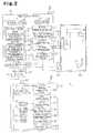
Fig. 1 is a block diagram representing a robot control system according to a first embodiment of the present invention;Fig. 2 is a block diagram representing a robot control system according to a second embodiment of the invention;Fig. 3 is a block diagram illustrating the robot control system in which a portable operating device and a robot control device wirelessly communicate with each other; andFig. 4 is a block diagram illustrating wireless communication between the portable operating device and the robot control device.- One embodiment of a robot control system according to the present invention will now be described with reference to
Fig. 1 . - As illustrated in
Fig. 1 , arobot control system 1 includes a robot control device RC for controlling operation of a robot R, the robot R installed in the space surrounded by asafety fence 52, a portable operating device TP for operating the robot R, and a charging device CU for charging the portable operating device TP. Wireless communication can be carried out between the portable operating device TP and the robot control device RC. An emergency stop of the robot R is caused when wireless communication is temporarily interrupted by noise generation or insufficient radio field intensity as the wireless communication is carried out. - The robot control device RC includes a
CPU 13 serving as a central processing unit, aRAM 14 serving as a temporary calculation area, asystem timer 2, amain control section 3 serving as a control center, ahard disk 5, anoperation control section 7, anactuation command section 8, aconnection monitoring section 12, awireless communication section 9, and a transceiver 10. Thesystem timer 2 measures current system time. Thehard disk 5 stores teaching data and the like. Theoperation control section 7 performs track calculation of the robot R and outputs the calculation result to theactuation command section 8 as an actuation signal. Theactuation command section 8 outputs a servo control signal for controlling rotation of servomotors of the robot R. Theconnection monitoring section 12 monitors whether the portable operating device TP and the robot control device RC are electrically connected to each other through the charging device CU. Thewireless communication section 9 and the transceiver 10 are used to carry out the wireless communication between the robot control device RC and the portable operating device TP. TheCPU 13, theRAM 14, thesystem timer 2, themain control section 3, thehard disk 5, theoperation control section 7, theactuation command section 8, theconnection monitoring section 12, thewireless communication section 9, and the transceiver 10 are connected to one another through a non-illustrated bus. Further, themain control section 3 has adisplay processing section 4, aninterpretation executing section 6, and an automaticoperation continuing section 11. Thedisplay processing section 4 generates display data, which is to be displayed on adisplay section 41 of the portable operating device TP, as a software program. Theinterpretation executing section 6 outputs a teaching signal to theoperation control section 7 based on teaching data, which is stored in thehard disk 5. When theconnection monitoring section 12 detects that the portable operating device TP is not electrically connected to the robot control device RC, the automaticoperation continuing section 11 continues the automatic operation of the robot R with the portable operating device TP disconnected from the robot control device RC. The automaticoperation continuing section 11 and theconnection monitoring section 12 will be described below in further detail. - The portable operating device TP has a
CPU 31 serving as a central processing unit, aRAM 32 serving as a temporary calculation area, thedisplay section 41, akeyboard 42, anemergency stop switch 43, an emergencystop monitoring section 33, adisplay control section 37, a keyentry monitoring section 36, awireless communication section 39, and a transceiver 20. Thedisplay section 41 displays various types of information. Thekeyboard 42 is used to enter various types of data such as teaching data. The emergencystop monitoring section 33 monitors an input of theemergency stop switch 43. Thedisplay control section 37 displays the display data on thedisplay section 41. The keyentry monitoring section 36 monitors key entry through thekeyboard 42. Thewireless communication section 39 and the transceiver 20 are used to carry out wireless communication between the robot control device RC and the portable operating device TP. Various types of data entered through thekeyboard 42 and a monitoring result indicating whether theemergency stop switch 43 has been pressed are transmitted from the portable operating device TP to the robot control device RC through thewireless communication section 39. The portable operating device TP also includes a chargingcircuit 34, asecondary battery 35, amain control section 15, and a chargingamount measurement device 38. The chargingcircuit 34 is electrically connected to the charging device CU. This charges thesecondary battery 35 so that the portable operating device TP can be operated. Themain control section 15 controls all the control sections of the portable operating device TP. Themain control section 15 also has a function for automatically disconnecting the power source of the portable operating device TP at a predetermined timing. The chargingamount measurement device 38 measures the charging amount of thesecondary battery 35 at predetermined time cycles. The measured charging amount is converted into digital data and stored by theRAM 32. - The charging device CU charges the portable operating device TP. The charging device CU supplies power from the robot control device RC to the portable operating device TP. In the first embodiment, by arranging the portable operating device TP at a predetermined position in the charging device CU, the charging
circuit 34 is electrically connected to the charging device CU so that thesecondary battery 35 in the portable operating device TP is charged. The power source of the charging device CU may be supplied from a commercial power supply, instead of the robot control device RC. - The
connection monitoring section 12 and the automaticoperation continuing section 11 will hereafter be described. - The
connection monitoring section 12 constantly monitors whether electric connection between the portable operating device TP and the robot control device RC is established. When the robot R is in automatic operation and theconnection monitoring section 12 detects that the electric connection between the portable operating device TP and the robot control device RC is not established, theconnection monitoring section 12 transmits a signal indicating the detection result to the automaticoperation continuing section 11. When the portable operating device TP is not connected to the charging device CU, the charging amount of thesecondary battery 35 of the portable operating device TP decreases as the time elapses. This eventually ends the wireless communication between the portable operating device TP and the robot control device RC. As a result, an emergency stop signal is input to the robot R and the production line is stopped. However, to prevent the problem, the automaticoperation continuing section 11 of the first embodiment carries out the procedure described below. - The automatic
operation continuing section 11 ends the wireless communication between the portable operating device TP and the robot control device RC and continues the automatic operation of the robot R solely through the robot control device RC with the portable operating device TP disconnected from therobot control system 1. More specifically, the automaticoperation continuing section 11 sends a wireless communication end request signal to the portable operating device TP through thewireless communication section 9. In response to an answer sent from the portable operating device TP to the automaticoperation continuing section 11, the automaticoperation continuing section 11 requests thewireless communication section 9 to end a wireless communication process. In this manner, the automaticoperation continuing section 11 ends the wireless communication between the portable operating device TP and the robot control device RC. Further, the automaticoperation continuing section 11 sends a signal for suspending generation of the display data and a process of transmission to the portable operating device TP to thedisplay processing section 4. At this stage, thedisplay processing section 4 may change the destination of transmission from the portable operating device TP to thehard disk 5 without suspending the generation of the display data. - When the robot R is in automatic operation, the robot control device RC may control operation of the robot R based on the teaching data stored in the
hard disk 5. Accordingly, when the robot R is in automatic operation, it is unnecessary to cause the robot control device RC and the portable operating device TP to communicate to each other in order to display change of the execution state and variable numbers of the teaching data on the portable operating device TP. In other words, even when wireless communication between the robot control device RC and the portable operating device TP is suspended, the operation of the robot R is controlled without causing a problem. When the portable operating device TP, which is disconnected from therobot control system 1, receives the wireless communication end request signal from the robot control device RC, it is desirable for the portable operating device TP to automatically disconnect the power source of the portable operating device TP. - As has been described, when the robot R is in the automatic operation and it is detected that the electric connection between the portable operating device TP and the robot control device RC is not established, the wireless communication is ended. Further, with the portable operating device TP disconnected from the
robot control system 1, the automatic operation of the robot R is continued solely through the robot control device RC without causing an emergency stop of the robot R. In this manner, automatic operation of the robot R is continued regardless of whether the portable operating device RC is connected to the charging device CU. This enhances work efficiency. Further, since automatic operation of the robot R is continued solely through the robot control device R without performing wireless communication, an emergency stop of the robot R caused by communication noise does not occur. Also, the portable operating device TP, which is disconnected from therobot control system 1, may be employed to perform robot teaching in other robot control systems. - When the robot R is in automatic operation and it is detected that an electric connection between the portable operating device TP and the robot control device RC is not established, the charging amount of the portable operating device TP is prevented from falling short by automatically disconnecting the power source of the portable operating device TP.
- A second embodiment of the present invention will hereafter be described with reference to
Fig. 2 . Detailed description of components of the second embodiment that are the same as or like corresponding components of the first embodiment will be omitted herein. The second embodiment is configured identically with the first embodiment except for analarm lamp 23 serving as alarm activation means, a radio fieldintensity measurement device 25 mounted in the vicinity of the robot R, aconnection cable 26, adisplay section 51 arranged in the charging device CU, a radio fieldintensity monitoring section 21, analarm activation section 22, a date/time obtaining section 27, a chargingamount obtaining section 28, and adisconnection detecting section 29. The radio fieldintensity monitoring section 21, thealarm activation section 22, the date/time obtaining section 27, the chargingamount obtaining section 28, and thedisconnection detecting section 29 are provided in the robot control device RC. - As illustrated in
Fig. 2 , the radio fieldintensity measurement device 25 is arranged in the vicinity or the interior of the robot R or attached to an inner side of thesafety fence 52. The radio fieldintensity measurement device 25 is connected to the radio fieldintensity monitoring section 21 through theconnection cable 26. In the second embodiment, the radio fieldintensity monitoring section 21, the radio fieldintensity measurement device 25, and theconnection cable 26 are configured as a radio field intensity monitoring means for monitoring the radio field intensity of the portable operating device TP. - The radio field
intensity monitoring section 21 determines whether the radio field intensity of the portable operating device TP is greater than a predetermined level. The predetermined level is set to such a minimum level that it allows wireless communication between the portable operating device TP and the robot control device RC in a range substantially covering the entire space surrounded by thesafety fence 52. Specifically, when the radio field intensity is smaller than the predetermined level, it is determined that the portable operating device TP is arranged outside the space surrounded by thesafety fence 52. In contrast, when the radio field intensity is greater than or equal to the predetermined level, it is determined that the portable operating device TP is arranged in the space surrounded by thesafety fence 52. - The
alarm activation section 22 turns on thealarm lamp 23 based on a determination result provided by the radio fieldintensity monitoring section 21. The date/time obtaining section 27 obtains the date and time of when the portable operating device TP was disconnected from therobot control system 1 from thesystem timer 2 and stores the date/time in thehard disk 5. The chargingamount obtaining section 28 inquires the portable operating device TP about the charging amount of thesecondary battery 35 at the time when the portable operating device TP is disconnected from therobot control system 1 and stores the result provided by the portable operating device TP in thehard disk 5. Thedisconnection detecting section 29 detects that the portable operating device TP is disconnected from therobot control system 1 and the automatic operation of the robot R continues. - The
display section 51 of the charging device CU displays at least one of the date/time and the charging amount of the secondary battery each at the time when the portable operating device TP is disconnected from therobot control system 1, in addition to a message informing the reader that the portable operating device TP is disconnected from therobot control system 1. - Operation of the second embodiment will hereafter be described. In order to end the wireless communication between the portable operating device TP and the robot control device RC and disconnect the portable operating device TP from the
robot control system 1 through the procedure of the automaticoperation continuing section 11 of the first embodiment, a pre-procedure as described below is performed. - When the robot R is in automatic operation and the
connection monitoring section 12 detects that the electric connection between the portable operating device TP and the robot control device RC is not established, the radio fieldintensity monitoring section 21 determines whether a measured radio field intensity is greater than a predetermined level. When it is determined that the radio field intensity is lower than the predetermined level, the radio fieldintensity monitoring section 21 informs the automaticoperation continuing section 11 of the determination result. In response, the automaticoperation continuing section 11 determines whether the portable operating device TP is outside the space surrounded by thesafety fence 52 and continues automatic operation of the robot R in accordance with the same procedure as the procedure of the first embodiment. - Contrastingly, when the measured radio field intensity is greater or equal to the predetermined level, the radio field
intensity monitoring section 21 informs thealarm activation section 22 of the result. This causes thealarm activation section 22 to turn on thealarm lamp 23. Specifically, thealarm activation section 22 blinks or illuminates thealarm lamp 23. Thealarm lamp 23 may be replaced by an audio device or other light. In this manner, when the portable operating device TP is in the space surrounded by the safety fence, an alarm is first activated to inform the operator of, for example, the fact that the portable operating device TP is in the space surrounded by the safety fence. It is desirable to carry out the procedure described below before and after the wireless communication is ended and automatic operation of the robot R is continued. - The date/
time obtaining section 27 obtains the date and time of when the wireless communication has ended and stores the date/time in thehard disk 5. The chargingamount obtaining section 28 queries the portable operating device TP about the charging amount of thesecondary battery 35 at the time immediately before wireless communication ended and stores the result provided by the portable operating device TP in thehard disk 5. When thedisconnection detecting section 29 detects that the portable operating device TP has been disconnected from therobot control system 1 and automatic operation of the robot R continues, thedisconnection detecting section 29 outputs a signal instructing display of the obtained date/time or charging amount to thedisplay processing section 4. Thedisplay processing section 4 thus displays the date/time or the charging amount of the charging device CU, in addition to the message informing the reader that the portable operating device TP is disconnected from therobot control system 1. - In this manner, by displaying at least one of the date/time and the charging amount at the time when the portable operating device TP has been disconnected from the
robot control system 1, the operator is allowed to know that the portable operating device TP has been disconnected from therobot control system 1 and automatic operation of the robot R continues, in addition to specific information such as the date/time or the charging amount at the time when such disconnection occurred. - Further, even if the power source of the portable operating device TP is disconnected after the portable operating device TP has been disconnected from the
robot control system 1, the operator is allowed to obtain the aforementioned information at the time when the portable operating device TP was disconnected from therobot control system 1 by means of the display section of the charging device CU. - In the second embodiment of the present invention described above, the transceiver 10 may be mounted in the vicinity or the interior of the robot R, instead of the radio field
intensity measurement device 25. In this case, the transceiver 10 and the robot control device RC are connected to each other with a wire and the radio field intensity is measured using the transceiver 10.
Claims (6)
- A robot control system having a robot (R), a portable operating device (TP) that is actuated by a rechargeable secondary battery (35) and used to operate the robot (R), a robot control device (RC) that is capable of wirelessly communicating with the portable operating device (TP) and performs automatic operation of the robot (R) based on teaching data input by the portable operating device (TP), and emergency stop means (43) that causes an emergency stop of the robot (R) when wireless communication between the portable operating device (TP) and the robot control device (RC) is interrupted, the robot control system comprising:charging means (CU) for charging the secondary battery (35) by electrically connecting the portable operating device (TP) to the robot control device (RC);connection monitoring means (12) for monitoring whether an electric connection between the portable operating device (TP) and the robot control device (RC) through the charging means (CU) is established;an automatic operation continuing section (11), wherein if the connection monitoring means (12) detects that the electric connection is not established when the robot (R) is in automatic operation, the automatic operation continuing section (11) ends wireless communication without causing an emergency stop of the robot (R) and continues automatic operation of the robot (R) with the portable operating device (TP) disconnected from the robot control system;a date/time obtaining section (27) for obtaining a date and time of when the portable operating device (TP) was disconnected from the robot control system; anddisplay means (51) for displaying the date and time.
- The robot control system according to claim 1, wherein, if the connection monitoring means (12) detects that the electric connection is not established when the robot (R) is in automatic operation, a power source of the portable operating device (TP) is disconnected.
- The robot control system according to claim 1 or 2, further comprising radio field intensity monitoring means (21) for monitoring radio field intensity when wireless communication is carried out by the portable operating device (TP) and alarm activation means (22) for activating an alarm when the radio field intensity is greater than or equal to a predetermined level.
- The robot control system according to any one of claims 1 to 3, further including a disconnection detecting section (29) that detects whether the portable operating device (TP) is disconnected from the robot control system, wherein the display means (51) displays a message informing a reader that the portable operating device (TP) is disconnected from the robot control system.
- The robot control system according to claim 4, further comprising a charging amount obtaining section (28) for obtaining a charging amount of the second battery (35) at the time when the portable operating device (TP) was disconnected from the robot control system, wherein the display means (51) displays the charging amount.
- The robot control system according to claim 4 or 5, wherein the display means (51) is a display section (51) mounted in the charging means (CU).
Applications Claiming Priority (2)
| Application Number | Priority Date | Filing Date | Title |
|---|---|---|---|
| JP2008086822 | 2008-03-28 | ||
| PCT/JP2009/055131WO2009119379A1 (en) | 2008-03-28 | 2009-03-17 | Robot control system |
Publications (3)
| Publication Number | Publication Date |
|---|---|
| EP2255932A1 EP2255932A1 (en) | 2010-12-01 |
| EP2255932A4 EP2255932A4 (en) | 2012-01-18 |
| EP2255932B1true EP2255932B1 (en) | 2015-03-04 |
Family
ID=41113576
Family Applications (1)
| Application Number | Title | Priority Date | Filing Date |
|---|---|---|---|
| EP09723910.7AActiveEP2255932B1 (en) | 2008-03-28 | 2009-03-17 | Robot control system |
Country Status (5)
| Country | Link |
|---|---|
| US (1) | US8660690B2 (en) |
| EP (1) | EP2255932B1 (en) |
| JP (2) | JPWO2009119379A1 (en) |
| CN (1) | CN101939145B (en) |
| WO (1) | WO2009119379A1 (en) |
Families Citing this family (39)
| Publication number | Priority date | Publication date | Assignee | Title |
|---|---|---|---|---|
| US9566710B2 (en) | 2011-06-02 | 2017-02-14 | Brain Corporation | Apparatus and methods for operating robotic devices using selective state space training |
| JP5863414B2 (en)* | 2011-11-25 | 2016-02-16 | 株式会社ダイヘン | Operating device and movable machine control system |
| US8738180B2 (en)* | 2011-12-14 | 2014-05-27 | GM Global Technology Operations LLC | Robot control during an e-stop event |
| JP6095361B2 (en)* | 2012-12-26 | 2017-03-15 | 株式会社ダイヘン | Robot control system |
| JP5590164B2 (en)* | 2013-01-28 | 2014-09-17 | 株式会社安川電機 | Robot system |
| US9764468B2 (en) | 2013-03-15 | 2017-09-19 | Brain Corporation | Adaptive predictor apparatus and methods |
| US9242372B2 (en) | 2013-05-31 | 2016-01-26 | Brain Corporation | Adaptive robotic interface apparatus and methods |
| US9792546B2 (en) | 2013-06-14 | 2017-10-17 | Brain Corporation | Hierarchical robotic controller apparatus and methods |
| US9314924B1 (en) | 2013-06-14 | 2016-04-19 | Brain Corporation | Predictive robotic controller apparatus and methods |
| JP6219619B2 (en)* | 2013-06-24 | 2017-10-25 | 株式会社ダイヘン | Charging system |
| US9579789B2 (en) | 2013-09-27 | 2017-02-28 | Brain Corporation | Apparatus and methods for training of robotic control arbitration |
| US9463571B2 (en) | 2013-11-01 | 2016-10-11 | Brian Corporation | Apparatus and methods for online training of robots |
| US9597797B2 (en) | 2013-11-01 | 2017-03-21 | Brain Corporation | Apparatus and methods for haptic training of robots |
| WO2015116271A2 (en)* | 2013-11-01 | 2015-08-06 | Brain Corporation | Apparatus and methods for operating robotic devices using selective state space training |
| US9358685B2 (en) | 2014-02-03 | 2016-06-07 | Brain Corporation | Apparatus and methods for control of robot actions based on corrective user inputs |
| US9043031B1 (en) | 2014-02-20 | 2015-05-26 | Westlake & Eanes Science & Technology Association | Low-cost, high-reliability controller for remotely operated robots |
| EP3112079A4 (en)* | 2014-02-24 | 2017-03-15 | Howon Co. Ltd. | Hybrid welder |
| JP6398237B2 (en)* | 2014-03-14 | 2018-10-03 | オムロン株式会社 | Radio control terminal, radio control device for control object, emergency stop control program |
| JP6267026B2 (en)* | 2014-03-19 | 2018-01-24 | Dmg森精機株式会社 | Machine tool control system |
| US9346167B2 (en) | 2014-04-29 | 2016-05-24 | Brain Corporation | Trainable convolutional network apparatus and methods for operating a robotic vehicle |
| US9630318B2 (en) | 2014-10-02 | 2017-04-25 | Brain Corporation | Feature detection apparatus and methods for training of robotic navigation |
| US9717387B1 (en) | 2015-02-26 | 2017-08-01 | Brain Corporation | Apparatus and methods for programming and training of robotic household appliances |
| US10661989B2 (en) | 2015-05-11 | 2020-05-26 | Murata Machinery, Ltd. | Automated equipment system, emergency stop terminal, and operation terminal control method |
| DE102015209899B4 (en)* | 2015-05-29 | 2019-06-19 | Kuka Roboter Gmbh | Selection of a device or an object with the help of a camera |
| AT517928A2 (en)* | 2015-11-06 | 2017-05-15 | Keba Ag | Control system for electrically controlled systems |
| JP6338617B2 (en)* | 2016-05-31 | 2018-06-06 | 株式会社アスコ | Teaching device |
| JP6744790B2 (en)* | 2016-09-06 | 2020-08-19 | シャープ株式会社 | Control system, control method, and control program |
| MX371369B (en)* | 2016-10-07 | 2020-01-28 | Norman R Byrne | Electrical power cord with intelligent switching. |
| CN107953330A (en)* | 2016-10-18 | 2018-04-24 | 珠海格力智能装备有限公司 | Robot and control method and device thereof |
| CN107962560B (en)* | 2016-10-18 | 2020-08-07 | 珠海格力智能装备有限公司 | Robot and control method and device thereof |
| JP6853675B2 (en)* | 2017-01-20 | 2021-03-31 | 川崎重工業株式会社 | Robot system and robot control device |
| DE102017208531A1 (en)* | 2017-05-19 | 2018-11-22 | Homag Gmbh | Remote control device |
| US10782665B2 (en)* | 2017-06-30 | 2020-09-22 | Cattron North America, Inc. | Wireless emergency stop systems, and corresponding methods of operating a wireless emergency stop system for a machine safety interface |
| JP7052641B2 (en) | 2018-08-27 | 2022-04-12 | 村田機械株式会社 | Wireless communication system and wireless communication method |
| AT521874A1 (en)* | 2018-10-31 | 2020-05-15 | Keba Ag | Method for operating a machine control system and corresponding machine control system |
| US11424561B2 (en) | 2019-07-03 | 2022-08-23 | Norman R. Byrne | Outlet-level electrical energy management system |
| CN110370288B (en)* | 2019-08-22 | 2021-09-17 | 苏州博众机器人有限公司 | Robot safety control method, device, equipment and storage medium |
| US20220404827A1 (en)* | 2019-11-15 | 2022-12-22 | Volvo Truck Corporation | Wireless control system for autonomous vehicles operating in an extended area |
| CN114536318B (en)* | 2020-11-24 | 2025-09-26 | 罗伯特·博世有限公司 | Mobile operating device and control method thereof |
Family Cites Families (17)
| Publication number | Priority date | Publication date | Assignee | Title |
|---|---|---|---|---|
| JPS61244493A (en)* | 1985-04-24 | 1986-10-30 | 株式会社東芝 | robot equipment |
| JP2672417B2 (en)* | 1991-08-15 | 1997-11-05 | ファナック株式会社 | Emergency stop circuit for teaching operation panel |
| US20020166127A1 (en)* | 1999-12-15 | 2002-11-07 | Hitachi America, Ltd. | System and method for providing advertisements in a wireless terminal |
| JP4032793B2 (en)* | 2002-03-27 | 2008-01-16 | ソニー株式会社 | Charging system, charging control method, robot apparatus, charging control program, and recording medium |
| JP2004281076A (en)* | 2003-03-12 | 2004-10-07 | Nikon Corp | Battery with indicator and electrical equipment |
| DE212005000036U1 (en)* | 2004-06-24 | 2007-02-15 | Abb Ab | Device for controlling a robot by a wireless programming handset unit |
| DE112006000262B4 (en) | 2005-01-26 | 2014-07-17 | Kabushiki Kaisha Yaskawa Denki | robot system |
| EP1716983B1 (en) | 2005-04-19 | 2008-05-14 | COMAU S.p.A. | Process for controlling industrial robots, and related robots, robot systems and computer programs |
| JP4609651B2 (en)* | 2005-05-19 | 2011-01-12 | 株式会社安川電機 | Automatic machine system and communication control method thereof |
| JP4080494B2 (en)* | 2005-06-10 | 2008-04-23 | ファナック株式会社 | Robot controller |
| US20060279545A1 (en)* | 2005-06-13 | 2006-12-14 | Jeng-Feng Lan | Sensor chip for laser optical mouse and related laser optical mouse |
| US20100106299A1 (en)* | 2005-06-20 | 2010-04-29 | Kabushiki Kaisha Yaskawa Denki | Automatic machine system and method for controlling communication thereof |
| JP4557839B2 (en)* | 2005-08-18 | 2010-10-06 | 日立電子サービス株式会社 | Connection system and connection method |
| US20070143479A1 (en)* | 2005-12-16 | 2007-06-21 | Putnam Michael A | Systems and methods for centralized custodial control |
| DE112007000394T5 (en)* | 2006-02-14 | 2008-12-24 | Kabushiki Kaisha Yaskawa Denki, Kitakyushu | robot system |
| AU2007343390A1 (en)* | 2007-01-10 | 2008-07-17 | Tomtom International B.V. | Navigation device and method for displaying navigation information |
| US7733418B2 (en)* | 2007-04-02 | 2010-06-08 | Alan Edward Kaplan | Encapsulated self-balancing remote video camera system |
- 2009
- 2009-03-17JPJP2010505549Apatent/JPWO2009119379A1/enactivePending
- 2009-03-17EPEP09723910.7Apatent/EP2255932B1/enactiveActive
- 2009-03-17WOPCT/JP2009/055131patent/WO2009119379A1/enactiveApplication Filing
- 2009-03-17USUS12/864,838patent/US8660690B2/enactiveActive
- 2009-03-17CNCN2009801050185Apatent/CN101939145B/enactiveActive
- 2015
- 2015-01-05JPJP2015000458Apatent/JP2015091622A/enactivePending
Also Published As
| Publication number | Publication date |
|---|---|
| JPWO2009119379A1 (en) | 2011-07-21 |
| US20110010006A1 (en) | 2011-01-13 |
| EP2255932A1 (en) | 2010-12-01 |
| JP2015091622A (en) | 2015-05-14 |
| US8660690B2 (en) | 2014-02-25 |
| WO2009119379A1 (en) | 2009-10-01 |
| CN101939145B (en) | 2012-08-29 |
| EP2255932A4 (en) | 2012-01-18 |
| CN101939145A (en) | 2011-01-05 |
Similar Documents
| Publication | Publication Date | Title |
|---|---|---|
| EP2255932B1 (en) | Robot control system | |
| EP1731978B1 (en) | Robot controller having portable operating part | |
| JP4826921B2 (en) | Automatic machine system and wireless communication method thereof | |
| US9711040B2 (en) | Wireless control terminal, wireless control apparatus for controlling control target, and emergency stop control program | |
| JP4697116B2 (en) | Automatic machine system | |
| US12015252B2 (en) | Wireless control in a cable feeder and puller system | |
| JP4609651B2 (en) | Automatic machine system and communication control method thereof | |
| CN112585988A (en) | Wireless communication system and wireless communication method | |
| US11382149B2 (en) | Method for establishing wireless communication | |
| JP6095361B2 (en) | Robot control system | |
| JP6214872B2 (en) | Robot control system and portable operation device | |
| JP7209188B2 (en) | Communication method, communication system, transmitter and receiver | |
| KR101443733B1 (en) | Beacon System | |
| TW393433B (en) | Electric device for moving shelves | |
| KR102545574B1 (en) | Danger warning system for heavy equipment | |
| JP2018176330A (en) | Industrial robot control system and industrial robot control method | |
| KR20160010704A (en) | System and method for managing network of welding machine |
Legal Events
| Date | Code | Title | Description |
|---|---|---|---|
| PUAI | Public reference made under article 153(3) epc to a published international application that has entered the european phase | Free format text:ORIGINAL CODE: 0009012 | |
| 17P | Request for examination filed | Effective date:20100726 | |
| AK | Designated contracting states | Kind code of ref document:A1 Designated state(s):AT BE BG CH CY CZ DE DK EE ES FI FR GB GR HR HU IE IS IT LI LT LU LV MC MK MT NL NO PL PT RO SE SI SK TR | |
| AX | Request for extension of the european patent | Extension state:AL BA RS | |
| DAX | Request for extension of the european patent (deleted) | ||
| A4 | Supplementary search report drawn up and despatched | Effective date:20111215 | |
| RIC1 | Information provided on ipc code assigned before grant | Ipc:B25J 13/06 20060101ALI20111209BHEP Ipc:B25J 9/16 20060101ALI20111209BHEP Ipc:G05B 19/42 20060101ALI20111209BHEP Ipc:B25J 9/22 20060101AFI20111209BHEP Ipc:B25J 19/06 20060101ALI20111209BHEP | |
| GRAP | Despatch of communication of intention to grant a patent | Free format text:ORIGINAL CODE: EPIDOSNIGR1 | |
| RIC1 | Information provided on ipc code assigned before grant | Ipc:B25J 9/22 20060101AFI20140910BHEP Ipc:G05B 19/42 20060101ALI20140910BHEP Ipc:B25J 9/16 20060101ALI20140910BHEP Ipc:B25J 13/06 20060101ALI20140910BHEP Ipc:B25J 19/06 20060101ALI20140910BHEP | |
| INTG | Intention to grant announced | Effective date:20140923 | |
| GRAS | Grant fee paid | Free format text:ORIGINAL CODE: EPIDOSNIGR3 | |
| GRAA | (expected) grant | Free format text:ORIGINAL CODE: 0009210 | |
| AK | Designated contracting states | Kind code of ref document:B1 Designated state(s):AT BE BG CH CY CZ DE DK EE ES FI FR GB GR HR HU IE IS IT LI LT LU LV MC MK MT NL NO PL PT RO SE SI SK TR | |
| REG | Reference to a national code | Ref country code:GB Ref legal event code:FG4D | |
| REG | Reference to a national code | Ref country code:CH Ref legal event code:EP | |
| REG | Reference to a national code | Ref country code:IE Ref legal event code:FG4D | |
| REG | Reference to a national code | Ref country code:AT Ref legal event code:REF Ref document number:713425 Country of ref document:AT Kind code of ref document:T Effective date:20150415 | |
| REG | Reference to a national code | Ref country code:DE Ref legal event code:R096 Ref document number:602009029769 Country of ref document:DE Effective date:20150423 | |
| REG | Reference to a national code | Ref country code:AT Ref legal event code:MK05 Ref document number:713425 Country of ref document:AT Kind code of ref document:T Effective date:20150304 Ref country code:NL Ref legal event code:VDEP Effective date:20150304 | |
| PG25 | Lapsed in a contracting state [announced via postgrant information from national office to epo] | Ref country code:NO Free format text:LAPSE BECAUSE OF FAILURE TO SUBMIT A TRANSLATION OF THE DESCRIPTION OR TO PAY THE FEE WITHIN THE PRESCRIBED TIME-LIMIT Effective date:20150604 Ref country code:ES Free format text:LAPSE BECAUSE OF FAILURE TO SUBMIT A TRANSLATION OF THE DESCRIPTION OR TO PAY THE FEE WITHIN THE PRESCRIBED TIME-LIMIT Effective date:20150304 Ref country code:SE Free format text:LAPSE BECAUSE OF FAILURE TO SUBMIT A TRANSLATION OF THE DESCRIPTION OR TO PAY THE FEE WITHIN THE PRESCRIBED TIME-LIMIT Effective date:20150304 Ref country code:LT Free format text:LAPSE BECAUSE OF FAILURE TO SUBMIT A TRANSLATION OF THE DESCRIPTION OR TO PAY THE FEE WITHIN THE PRESCRIBED TIME-LIMIT Effective date:20150304 Ref country code:HR Free format text:LAPSE BECAUSE OF FAILURE TO SUBMIT A TRANSLATION OF THE DESCRIPTION OR TO PAY THE FEE WITHIN THE PRESCRIBED TIME-LIMIT Effective date:20150304 Ref country code:FI Free format text:LAPSE BECAUSE OF FAILURE TO SUBMIT A TRANSLATION OF THE DESCRIPTION OR TO PAY THE FEE WITHIN THE PRESCRIBED TIME-LIMIT Effective date:20150304 | |
| REG | Reference to a national code | Ref country code:LT Ref legal event code:MG4D | |
| PG25 | Lapsed in a contracting state [announced via postgrant information from national office to epo] | Ref country code:AT Free format text:LAPSE BECAUSE OF FAILURE TO SUBMIT A TRANSLATION OF THE DESCRIPTION OR TO PAY THE FEE WITHIN THE PRESCRIBED TIME-LIMIT Effective date:20150304 Ref country code:LV Free format text:LAPSE BECAUSE OF FAILURE TO SUBMIT A TRANSLATION OF THE DESCRIPTION OR TO PAY THE FEE WITHIN THE PRESCRIBED TIME-LIMIT Effective date:20150304 Ref country code:GR Free format text:LAPSE BECAUSE OF FAILURE TO SUBMIT A TRANSLATION OF THE DESCRIPTION OR TO PAY THE FEE WITHIN THE PRESCRIBED TIME-LIMIT Effective date:20150605 | |
| PG25 | Lapsed in a contracting state [announced via postgrant information from national office to epo] | Ref country code:NL Free format text:LAPSE BECAUSE OF FAILURE TO SUBMIT A TRANSLATION OF THE DESCRIPTION OR TO PAY THE FEE WITHIN THE PRESCRIBED TIME-LIMIT Effective date:20150304 | |
| PG25 | Lapsed in a contracting state [announced via postgrant information from national office to epo] | Ref country code:CZ Free format text:LAPSE BECAUSE OF FAILURE TO SUBMIT A TRANSLATION OF THE DESCRIPTION OR TO PAY THE FEE WITHIN THE PRESCRIBED TIME-LIMIT Effective date:20150304 Ref country code:EE Free format text:LAPSE BECAUSE OF FAILURE TO SUBMIT A TRANSLATION OF THE DESCRIPTION OR TO PAY THE FEE WITHIN THE PRESCRIBED TIME-LIMIT Effective date:20150304 Ref country code:RO Free format text:LAPSE BECAUSE OF FAILURE TO SUBMIT A TRANSLATION OF THE DESCRIPTION OR TO PAY THE FEE WITHIN THE PRESCRIBED TIME-LIMIT Effective date:20150304 Ref country code:SK Free format text:LAPSE BECAUSE OF FAILURE TO SUBMIT A TRANSLATION OF THE DESCRIPTION OR TO PAY THE FEE WITHIN THE PRESCRIBED TIME-LIMIT Effective date:20150304 Ref country code:PT Free format text:LAPSE BECAUSE OF FAILURE TO SUBMIT A TRANSLATION OF THE DESCRIPTION OR TO PAY THE FEE WITHIN THE PRESCRIBED TIME-LIMIT Effective date:20150706 | |
| REG | Reference to a national code | Ref country code:CH Ref legal event code:PL | |
| PG25 | Lapsed in a contracting state [announced via postgrant information from national office to epo] | Ref country code:IS Free format text:LAPSE BECAUSE OF FAILURE TO SUBMIT A TRANSLATION OF THE DESCRIPTION OR TO PAY THE FEE WITHIN THE PRESCRIBED TIME-LIMIT Effective date:20150704 Ref country code:PL Free format text:LAPSE BECAUSE OF FAILURE TO SUBMIT A TRANSLATION OF THE DESCRIPTION OR TO PAY THE FEE WITHIN THE PRESCRIBED TIME-LIMIT Effective date:20150304 | |
| REG | Reference to a national code | Ref country code:DE Ref legal event code:R097 Ref document number:602009029769 Country of ref document:DE | |
| PG25 | Lapsed in a contracting state [announced via postgrant information from national office to epo] | Ref country code:IT Free format text:LAPSE BECAUSE OF FAILURE TO SUBMIT A TRANSLATION OF THE DESCRIPTION OR TO PAY THE FEE WITHIN THE PRESCRIBED TIME-LIMIT Effective date:20150304 | |
| PLBE | No opposition filed within time limit | Free format text:ORIGINAL CODE: 0009261 | |
| STAA | Information on the status of an ep patent application or granted ep patent | Free format text:STATUS: NO OPPOSITION FILED WITHIN TIME LIMIT | |
| REG | Reference to a national code | Ref country code:IE Ref legal event code:MM4A | |
| PG25 | Lapsed in a contracting state [announced via postgrant information from national office to epo] | Ref country code:MC Free format text:LAPSE BECAUSE OF FAILURE TO SUBMIT A TRANSLATION OF THE DESCRIPTION OR TO PAY THE FEE WITHIN THE PRESCRIBED TIME-LIMIT Effective date:20150304 Ref country code:CH Free format text:LAPSE BECAUSE OF NON-PAYMENT OF DUE FEES Effective date:20150331 Ref country code:IE Free format text:LAPSE BECAUSE OF NON-PAYMENT OF DUE FEES Effective date:20150317 Ref country code:DK Free format text:LAPSE BECAUSE OF FAILURE TO SUBMIT A TRANSLATION OF THE DESCRIPTION OR TO PAY THE FEE WITHIN THE PRESCRIBED TIME-LIMIT Effective date:20150304 Ref country code:LI Free format text:LAPSE BECAUSE OF NON-PAYMENT OF DUE FEES Effective date:20150331 | |
| 26N | No opposition filed | Effective date:20151207 | |
| REG | Reference to a national code | Ref country code:FR Ref legal event code:ST Effective date:20160112 | |
| GBPC | Gb: european patent ceased through non-payment of renewal fee | Effective date:20150604 | |
| PG25 | Lapsed in a contracting state [announced via postgrant information from national office to epo] | Ref country code:SI Free format text:LAPSE BECAUSE OF FAILURE TO SUBMIT A TRANSLATION OF THE DESCRIPTION OR TO PAY THE FEE WITHIN THE PRESCRIBED TIME-LIMIT Effective date:20150304 | |
| PG25 | Lapsed in a contracting state [announced via postgrant information from national office to epo] | Ref country code:GB Free format text:LAPSE BECAUSE OF NON-PAYMENT OF DUE FEES Effective date:20150604 | |
| PG25 | Lapsed in a contracting state [announced via postgrant information from national office to epo] | Ref country code:FR Free format text:LAPSE BECAUSE OF NON-PAYMENT OF DUE FEES Effective date:20150504 | |
| PG25 | Lapsed in a contracting state [announced via postgrant information from national office to epo] | Ref country code:BE Free format text:LAPSE BECAUSE OF FAILURE TO SUBMIT A TRANSLATION OF THE DESCRIPTION OR TO PAY THE FEE WITHIN THE PRESCRIBED TIME-LIMIT Effective date:20150304 | |
| PG25 | Lapsed in a contracting state [announced via postgrant information from national office to epo] | Ref country code:MT Free format text:LAPSE BECAUSE OF FAILURE TO SUBMIT A TRANSLATION OF THE DESCRIPTION OR TO PAY THE FEE WITHIN THE PRESCRIBED TIME-LIMIT Effective date:20150304 | |
| PG25 | Lapsed in a contracting state [announced via postgrant information from national office to epo] | Ref country code:HU Free format text:LAPSE BECAUSE OF FAILURE TO SUBMIT A TRANSLATION OF THE DESCRIPTION OR TO PAY THE FEE WITHIN THE PRESCRIBED TIME-LIMIT; INVALID AB INITIO Effective date:20090317 Ref country code:BG Free format text:LAPSE BECAUSE OF FAILURE TO SUBMIT A TRANSLATION OF THE DESCRIPTION OR TO PAY THE FEE WITHIN THE PRESCRIBED TIME-LIMIT Effective date:20150304 | |
| PG25 | Lapsed in a contracting state [announced via postgrant information from national office to epo] | Ref country code:CY Free format text:LAPSE BECAUSE OF FAILURE TO SUBMIT A TRANSLATION OF THE DESCRIPTION OR TO PAY THE FEE WITHIN THE PRESCRIBED TIME-LIMIT Effective date:20150304 | |
| PG25 | Lapsed in a contracting state [announced via postgrant information from national office to epo] | Ref country code:TR Free format text:LAPSE BECAUSE OF FAILURE TO SUBMIT A TRANSLATION OF THE DESCRIPTION OR TO PAY THE FEE WITHIN THE PRESCRIBED TIME-LIMIT Effective date:20150304 | |
| PG25 | Lapsed in a contracting state [announced via postgrant information from national office to epo] | Ref country code:LU Free format text:LAPSE BECAUSE OF NON-PAYMENT OF DUE FEES Effective date:20150317 | |
| PG25 | Lapsed in a contracting state [announced via postgrant information from national office to epo] | Ref country code:MK Free format text:LAPSE BECAUSE OF FAILURE TO SUBMIT A TRANSLATION OF THE DESCRIPTION OR TO PAY THE FEE WITHIN THE PRESCRIBED TIME-LIMIT Effective date:20150304 | |
| REG | Reference to a national code | Ref country code:DE Ref legal event code:R081 Ref document number:602009029769 Country of ref document:DE Owner name:DAIHEN CORP., OSAKA-SHI, JP Free format text:FORMER OWNERS: DAIHEN CORP., OSAKA-SHI, OSAKA, JP; NACHI-FUJIKOSHI CORP., TOYAMA-SHI, TOYAMA, JP | |
| PGFP | Annual fee paid to national office [announced via postgrant information from national office to epo] | Ref country code:DE Payment date:20250128 Year of fee payment:17 |