EP2254810B1 - Cartridge for preparation of a liquid comprising puncturable delivery wall - Google Patents
Cartridge for preparation of a liquid comprising puncturable delivery wallDownload PDFInfo
- Publication number
- EP2254810B1 EP2254810B1EP09722021.4AEP09722021AEP2254810B1EP 2254810 B1EP2254810 B1EP 2254810B1EP 09722021 AEP09722021 AEP 09722021AEP 2254810 B1EP2254810 B1EP 2254810B1
- Authority
- EP
- European Patent Office
- Prior art keywords
- cartridge
- liquid
- outlet
- chamber
- water
- Prior art date
- Legal status (The legal status is an assumption and is not a legal conclusion. Google has not performed a legal analysis and makes no representation as to the accuracy of the status listed.)
- Not-in-force
Links
- 239000007788liquidSubstances0.000titleclaimsdescription78
- 238000002360preparation methodMethods0.000titledescription9
- XLYOFNOQVPJJNP-UHFFFAOYSA-NwaterSubstancesOXLYOFNOQVPJJNP-UHFFFAOYSA-N0.000claimsdescription82
- 238000002347injectionMethods0.000claimsdescription43
- 239000007924injectionSubstances0.000claimsdescription43
- 239000000126substanceSubstances0.000claimsdescription31
- 235000013305foodNutrition0.000claimsdescription26
- 235000013361beverageNutrition0.000claimsdescription15
- 238000004519manufacturing processMethods0.000claimsdescription6
- 238000007789sealingMethods0.000claimsdescription2
- 239000012528membraneSubstances0.000description72
- 239000004615ingredientSubstances0.000description18
- 238000004090dissolutionMethods0.000description8
- 239000004411aluminiumSubstances0.000description7
- XAGFODPZIPBFFR-UHFFFAOYSA-NaluminiumChemical compound[Al]XAGFODPZIPBFFR-UHFFFAOYSA-N0.000description7
- 229910052782aluminiumInorganic materials0.000description7
- 239000004743PolypropyleneSubstances0.000description6
- 230000003111delayed effectEffects0.000description6
- 239000004033plasticSubstances0.000description6
- 229920003023plasticPolymers0.000description6
- 230000000694effectsEffects0.000description5
- 230000003993interactionEffects0.000description5
- 239000000463materialSubstances0.000description5
- 230000001681protective effectEffects0.000description5
- 239000007787solidSubstances0.000description5
- 230000004888barrier functionEffects0.000description4
- 239000007789gasSubstances0.000description4
- 235000021056liquid foodNutrition0.000description4
- 238000002156mixingMethods0.000description4
- -1polypropylenePolymers0.000description4
- 229920001155polypropylenePolymers0.000description4
- 239000012530fluidSubstances0.000description3
- 235000012041food componentNutrition0.000description3
- 239000005417food ingredientSubstances0.000description3
- 235000013350formula milkNutrition0.000description3
- 235000016709nutritionNutrition0.000description3
- 229920000642polymerPolymers0.000description3
- IJGRMHOSHXDMSA-UHFFFAOYSA-NAtomic nitrogenChemical compoundN#NIJGRMHOSHXDMSA-UHFFFAOYSA-N0.000description2
- 229920000219Ethylene vinyl alcoholPolymers0.000description2
- 241001122767TheaceaeSpecies0.000description2
- 230000000903blocking effectEffects0.000description2
- 239000002775capsuleSubstances0.000description2
- UFRKOOWSQGXVKV-UHFFFAOYSA-Nethene;ethenolChemical compoundC=C.OC=CUFRKOOWSQGXVKV-UHFFFAOYSA-N0.000description2
- 239000004715ethylene vinyl alcoholSubstances0.000description2
- 239000000843powderSubstances0.000description2
- 102000004169proteins and genesHuman genes0.000description2
- 108090000623proteins and genesProteins0.000description2
- QVGXLLKOCUKJST-UHFFFAOYSA-Natomic oxygenChemical compound[O]QVGXLLKOCUKJST-UHFFFAOYSA-N0.000description1
- 238000011109contaminationMethods0.000description1
- 230000008094contradictory effectEffects0.000description1
- 238000010790dilutionMethods0.000description1
- 239000012895dilutionSubstances0.000description1
- 239000006185dispersionSubstances0.000description1
- 238000001914filtrationMethods0.000description1
- 239000006260foamSubstances0.000description1
- 239000011521glassSubstances0.000description1
- 238000000265homogenisationMethods0.000description1
- 238000003780insertionMethods0.000description1
- 230000037431insertionEffects0.000description1
- 239000000203mixtureSubstances0.000description1
- 229910052757nitrogenInorganic materials0.000description1
- 235000015097nutrientsNutrition0.000description1
- 239000001301oxygenSubstances0.000description1
- 229910052760oxygenInorganic materials0.000description1
- 230000002093peripheral effectEffects0.000description1
- 230000001737promoting effectEffects0.000description1
- 235000014347soupsNutrition0.000description1
- 239000007921spraySubstances0.000description1
- 230000003319supportive effectEffects0.000description1
- 229920001169thermoplasticPolymers0.000description1
- 239000004416thermosoftening plasticSubstances0.000description1
Images


Classifications
- B—PERFORMING OPERATIONS; TRANSPORTING
- B65—CONVEYING; PACKING; STORING; HANDLING THIN OR FILAMENTARY MATERIAL
- B65D—CONTAINERS FOR STORAGE OR TRANSPORT OF ARTICLES OR MATERIALS, e.g. BAGS, BARRELS, BOTTLES, BOXES, CANS, CARTONS, CRATES, DRUMS, JARS, TANKS, HOPPERS, FORWARDING CONTAINERS; ACCESSORIES, CLOSURES, OR FITTINGS THEREFOR; PACKAGING ELEMENTS; PACKAGES
- B65D85/00—Containers, packaging elements or packages, specially adapted for particular articles or materials
- B65D85/70—Containers, packaging elements or packages, specially adapted for particular articles or materials for materials not otherwise provided for
- B65D85/804—Disposable containers or packages with contents which are mixed, infused or dissolved in situ, i.e. without having been previously removed from the package
- B65D85/8043—Packages adapted to allow liquid to pass through the contents
- B65D85/8055—Means for influencing the liquid flow inside the package
- B—PERFORMING OPERATIONS; TRANSPORTING
- B65—CONVEYING; PACKING; STORING; HANDLING THIN OR FILAMENTARY MATERIAL
- B65D—CONTAINERS FOR STORAGE OR TRANSPORT OF ARTICLES OR MATERIALS, e.g. BAGS, BARRELS, BOTTLES, BOXES, CANS, CARTONS, CRATES, DRUMS, JARS, TANKS, HOPPERS, FORWARDING CONTAINERS; ACCESSORIES, CLOSURES, OR FITTINGS THEREFOR; PACKAGING ELEMENTS; PACKAGES
- B65D85/00—Containers, packaging elements or packages, specially adapted for particular articles or materials
- B65D85/70—Containers, packaging elements or packages, specially adapted for particular articles or materials for materials not otherwise provided for
- B65D85/804—Disposable containers or packages with contents which are mixed, infused or dissolved in situ, i.e. without having been previously removed from the package
- B65D85/8043—Packages adapted to allow liquid to pass through the contents
- B65D85/8052—Details of the outlet
Definitions
- the present inventionrelates to a single-use cartridge containing an ingredient intended to interact with an amount of water injected in the cartridge for preparing a liquid.
- the cartridgeis typically used for preparing liquid food such as a nutritional liquid preparation, e.g., an infant formula, a soup or a beverage.
- the cartridgeis typically inserted in a dispensing machine adapted for receiving the cartridge, for injecting water at a suitable temperature and therefore preparing quickly, hygienically and conveniently a liquid food from said cartridge.
- a cartridge for preparing liquid food in a dispensing machinesuch as an in-home delivery system, is known for example in WO 03/059778 .
- the cartridgecomprises a cup forming a chamber for holding the food ingredient, a puncturable delivery wall such as a flexible membrane forming a physical barrier that retains the ingredient in the chamber, a puncturing system for puncturing the wall by effect of water filling the chamber under pressure.
- the cartridgefurther comprises a collecting area to collect the liquid which passes through the punctured membrane and at least one outlet for delivering the liquid from the collecting area.
- a delayed opening of the delivery wall of the ingredient's chamber of the cartridgeensures that the largest amount of ingredient is wetted before the liquid can leave the cartridge. This delayed opening provides a way to reduce the preferred flow shortcut through the substance. It also ensures a full dissolution of the substance when this one is soluble. Indeed, for certain ingredients, it is necessary to obtain a complete dissolution of the substance in the chamber before the liquid can be released.
- openingmust occur when the chamber is entirely filled and mixed with the ingredient and a liquid mixture is obtained. If the membrane opens too early, dry ingredient such as solid lumps may be left in the chamber. This may result in a volume of delivery food liquid that does not reach the required concentration. For certain liquid preparations such as infant formula or other nutritional preparations, a low concentration of the delivered liquid is not acceptable, in particular for persons for which the intake of food and nutrients must be accurately controlled.
- a significant amount of foam on the delivered liquidmay be not desired because it could provide a too high solid concentration of the final liquid and/or a texture which is not appropriate for its intended use.
- the flow of liquidmust be delivered in a controlled manner, preferably without risk of blocking, without splashing, therefore, preferably smoothly through the delivery outlet, while still an effective mixing or homogenization can take place in the chamber of the cartridge.
- Thismay be contradictory with the need for a certain opening delay in the cartridge to obtain sufficient interaction between water and the substance in the cartridge. Indeed, a delayed opening requires creating a rise of pressure in the chamber till the chamber is opened.
- the chamber opense.g., the delivery membrane ruptures, the liquid tends to flow as powerful jets through the created openings.
- the membranetends to collapse forming restriction areas which are prone to form high velocity jets in many possible uncontrolled directions.
- existing cartridgesare not properly designed to provide both a delayed opening allowing a proper interaction between water and the substance, e.g., a proper dissolution or brewing of the ingredient in the cartridge, and a slow and directionally controlled delivery flow that enables a hygienic delivery, such as a direct delivery in the receiving receptacle, i.e., a baby bottle, a cup or glass, with a reduced risk of contamination outside of the receptacle.
- a hygienic deliverysuch as a direct delivery in the receiving receptacle, i.e., a baby bottle, a cup or glass
- WO2005/016094relates to a coffee or tea pod comprising a spiked pod into which is positioned a lower filter layer and a foiled envelope.
- the water pressureforces both the lower filter layer and the foiled envelope against the spikes of the spiked pod.
- the punctures caused by the spikesallow the brewed beverage to pass therethrough while substantially maintaining the brewing material therein.
- the beverageleaves the pod through a plurality of holes distributed in the bottom of the pod.
- EP1555218B1relates to a cartridge for coffee or a soluble substance comprising a container, a lid and a filter designed to be positioned inside the container and above the bottom wall through which the beverage leaves.
- the bottom wallhas a breakable portion designed to break when the liquid inside the cartridge reaches a pre-set pressure so as to form an aperture to allow beverage to be extracted from the cartridge.
- the breakable portionis obtained by means of grooves formed in a weakened portion of the bottom wall.
- One problemis that it is relatively difficult to control the resistance of the weakened portion that opens under the sole effect of the pressure of fluid in the cartridge to ensure a reproducible delay of the opening time from cartridge to cartridge. Thus, inconsistent opening times will cause beverages having different solids concentration and thus different quality.
- EP1580143B1relates to a cartridge for extracting a beverage from particulate substance contained therein by means of water under pressure, the cartridge comprising a cup portion with a cup port and a lid for closing the cup portion; the base of the cup portion comprising a plurality of ridges directly formed thereon and protruding towards the internal volume of the cartridge and a filter placed on the ridges to define a fine canalization between the filtering means and the cup port.
- the delayed openingis obtained by means of a slit or orifice valve that opens under an internal pre-set pressure.
- the filtermust be sufficiently thick and rigid enough to resist the pressure and avoid its collapsing in the canalization.
- a disadvantageis the use of thick plastic material to resist the pressure and the high number of pieces necessary to form the cartridge which makes the cartridge complex and costly to manufacture.
- WO2007/039032relates to a cartridge of the same principle as the one of EP1580143B1 but with a safety cap which is mounted on the external surface of the cup port and partially closes the external open end thereof.
- Document WO2008/087553discloses a cartridge according to the preamble of claim 1.
- the present inventionaims at improving a cartridge for solving the above-mentioned problems and possibly others.
- the cartridge of the inventionaims at improving the consistency of the flow of the liquid that exits the cartridge and at improving the dissolution or brewing of the substance contained in the cartridge.
- the cartridge of the inventioncontains a food substance adapted to interact with water injected in the cartridge to produce a food liquid that is dispensed from the cartridge.
- the cartridgecomprises:
- At least one support surfaceis arranged in the flow path between the puncturing structure and the at least one outlet and/or is placed above and/or adjacent the at least one outlet.
- the cartridge of the inventionprevents the membrane from collapsing in the collecting area or from forming blocking areas for the flow and therefore, the cartridge ensures a more regular flow path and a controlled direction of the liquid flow path downstream of the punctured membrane.
- the flow pathmay also be controlled to change direction in such a way that it can slow down sufficiently and can be released in a smoother way.
- the support structureis placed between the puncturable delivery wall and the bottom wall of the cup forming the collecting area.
- the support structureis preferably connected to the bottom wall of the cup. It can be integral to the bottom wall and extending therefrom.
- the puncturing structureis also preferably connected to the bottom wall, most preferably, this structure is an integral part of the bottom wall of the cartridge.
- the cartridgecan comprise a series of outlets.
- the outletsare preferably placed or gathered in or closed to the centre of the collecting area.
- the number of outletsmay vary. For instance, the number of outlets may be between 1 and 10.
- the outletcan also be a flow guiding duct extending from the outlet(s).
- the outletsmay be placed circumferentially around the guiding duct to collect the liquid flowing transversally from the collecting area.
- At least one support surface of the support structureforms a portion of disc or a dome that extends transversally beyond the outlet or the series of outlets.
- the small portion of disc or domeis preferably larger than or substantially equal to the largest transversal dimension of the outlet or the series of outlets.
- the outlet(s)can so be maintained with a defined opening surface area, with a reduced risk of possible restriction formed by a deformed part of the delivery wall.
- the liquid outlet(s)is (are) thus neither blocked nor restricted by the delivery wall.
- the portion of discpreferentially may be a flat or slightly convex upper surface to support the delivery wall without risk of rupture of it.
- the support structurecomprises portions of ridges placed in the flow path between the puncturing means and the at least one outlet.
- the portions of ridgesare placed concentrically around the liquid outlet(s), with flow passages in-between, for breaking the flow of liquid towards the outlet.
- the portion of ridgesmay take different forms and dimensions.
- the portions of ridgesprovide support but also may break the flow of liquid towards the outlet(s).
- the portions of ridgescan radially surround the outlet, and be placed at a radial distance from the outlet.
- the portions of ridgesform a concentric discontinuous pattern to provide the flow with a tortuous slowing down path toward the outlet.
- the portions of ridgesdelimit a series of circumferential channels and of radial passages between the ridges for the liquid to be slowed down and guided toward the outlet(s).
- the puncturing structuremay form a plurality of small protrusions.
- the protrusionshave a sufficiently sharp edge or tip to perforate the puncturable wall when the wall is pressed thereon by the effect of the pressure that builds in the cartridge.
- the puncture structuremay comprise puncture surfaces of smaller width or section than the width or section of the support surface of support structure. Therefore, the puncturable wall will resist to perforation on the support structure thus creating suitable gaps for flow path toward the outlets whereas it will perforate by relatively defined openings against the protrusions of the puncturing structure.
- the protrusionscan be arranged concentrically around the outlet(s). Therefore, different streams of liquid flow are created through the delivery wall of the chamber to ensure also a proper circulation of water through the substance in the chamber as well as a homogeneous flow of liquid which collects in the collecting area.
- the protrusions of the puncturing structuremay be formed of a plurality of a sharp puncturing forms like crosses, cones or blades. In a preferred configuration, the protrusions form crosses in their transversal section.
- the support structurefurther comprises portions of ridges placed in a radial direction of the bottom surface of the cup.
- the radially oriented portions of ridgecan provide an additional support of the delivery wall, in particular, when placed between the protrusions. Therefore, the wall is prevented from collapsing between the protrusions. Hence, the liquid is better guided in the collecting areas.
- the cupis an injected plastic member such as in polypropylene or any other suitable food grade plastic material.
- the delivery wallis preferably a flexible membrane made of aluminium and/or polymer.
- the delivery wallcan be sealed on an inner annular step portion provided in the cup.
- the delivery wallcan remain unsealed onto the support structure as the pressure.
- the cupis further sealed by a puncturable membrane forming the lid of the cartridge.
- the lid of the cartridgecomprises at least one injection orifice of small size for forming a jet of the liquid entering the chamber containing the food substance.
- the at least one injection orificehas preferably a diameter of less than 1.0 mm, most preferably comprised between 0.4 and 0.8 mm. Such small sizes of the orifice generate high momentum of the liquid in the cartridge and therefore enhance the dissolution or dispersion of the substance, in particular, fat and protein powder.
- the at least one injection orificeis preferably placed in a location which is not axially aligned, i.e., off-centred, relative to the centreline of the cartridge.
- the number of orificesis low, preferably, less than 5, most preferably one or two orifices are formed in the lid.
- the lidcan further comprise a protective cover placed externally of an under-layer of the lid comprising the jet-forming orifice(s), for ensuring protection of the substance contained in the chamber before use of the cartridge.
- a protective coverplaced externally of an under-layer of the lid comprising the jet-forming orifice(s), for ensuring protection of the substance contained in the chamber before use of the cartridge.
- Such protective covercan be a peel-off or a puncturable membrane for instance.
- the injection orificeis configured to orient a jet of liquid in a direction which is substantially normal to the puncturable delivery wall.
- substantially normal directionit is meant that the configuration of the jet of liquid is not of more than 10 degrees from the normal to the delivery wall.
- the injection orificeis configured to orient a jet towards the support surface of the support structure configured to support the delivery wall.
- a cartridge systemwhich comprises: a cartridge and a beverage production device for holding said cartridge and comprising a water injection intruding member.
- the water injection intruding member of the deviceis designed to inject water in the cartridge under pressure for interacting with a food to produce a food liquid that is dispensed from the cartridge.
- the cartridgecomprises a cup having a chamber for holding the food substance, a lid and a delivery wall puncturable by the water injection intruding member that holds the substance in the chamber, a puncturing structure to puncture at least one opening in the delivery wall as a response of water filling the chamber, a collecting area for collecting the liquid passing through the delivery wall in a substantially axial direction. The collecting is placed downstream the puncturable delivery wall. At least one liquid outlet in the collecting area for allowing the liquid to leave the collecting area.
- the cartridgecomprises a support structure comprising at least one support surface configured to support at least one portion of the delivery wall and wherein the water injection intruding member is configured to inject water in the cartridge under pressure in a direction focused towards said support surface.
- Such a configuration of the water injecting means relative to the cartridgeensures that the delivery wall is not pierced accidentally at a non-desired point and it also provides an improved mixing of water in the chamber of the cartridge by promoting reflections of the water jet in the chamber.
- the water injection intruding memberis so arranged that the water jet hits the delivery wall which is supported by the membrane. Therefore, since the wall is supported by the support surface underneath, the water jet does not perforate the wall due to the localized water pressure on the wall, e.g., an aluminium or plastic membrane.
- the water jetis further diverted in the direction of the chamber and can create a vortex in the chamber that promotes an improved interaction between water and the substance, e.g., a good mixing.
- the delivery wallcan be a puncturable membrane that is gastight for opening under pressure against the puncture structure, such as an aluminium membrane or a non-porous polymer such as PP.
- the delivery wallcan be a filter such as a paper filter or a porous filter membrane.
- the filteris supported by the support structure for resisting to the pressure in the chamber without tearing and/or collapsing and closing the flow gap in the collecting area.
- the delivery wallcan be formed by the superposition of both a puncturable non-porous membrane and a filter.
- the water injection intruding memberhas a piercing tip for being able to perforate the lid.
- the memberhas a water outlet which is arranged to direct at least one jet of water in the direction towards the support surface of the cartridge.
- the directionis towards the centre of the cartridge.
- the water outletmay be designed to provide a fan spray of waterforming a cone which centreline is directed towards the support surface.
- the water injection intruding membercan be located in an off-centred location relative to the centre of the cartridge.
- the water injection intruding membercan also be aligned axially in the centre of the cartridge. More than one water injection intruding members can enter the cartridge at different locations.
- the cartridgehas a support surface which is transversally oriented to the longitudinal axis of the cartridge and the water injection intruding member is off-centred relative to said axis.
- the cartridgehas a support surface which is transversally oriented to the longitudinal axis of the cartridge and the water injection intruding member is aligned with said axis.
- the inventionrelates to a cartridge system comprising:
- the water injection meanscomprises a water injection intruding member of the beverage production device as aforementioned.
- the water injection meanscomprises a lid of the cartridge comprising at least one small orifice configured to form a high-momentum jet of liquid (i.e., water) in the chamber as aforementioned.
- the jet-forming orificescan be oriented in a direction normal to the puncturable delivery wall of the cartridge or alternatively be inclined towards the support surface of the support structure.
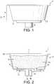
- a cartridge of the present invention in a first modeis illustrated in figures 1 to 7 .
- the cartridge 1comprises a cup 2 preferably made of plastics. Suitable thermoplastics can be polypropylene or a multi-layer of polypropylene layers and a gas barrier layer such as EVOH. A possible multi-layer can be PP-EVOH-PP.
- the cupis preferably obtained by injection in one piece.
- the cupcomprises a main body portion 3, a stepped portion 4 and collection area 5 and a tubular outlet portion 6.
- the lid 7can be a flexible membrane which forms the water injection side of the cartridge. Injection of water is typically performed by piercing the membrane at one or several points in the membrane by means of a perforating system of a beverage preparation machine (not shown).
- the membranecan be typically made of a thin laminate of aluminium and/or polymers. For instance, the membrane comprises a laminate of PET and a gas barrier layer such as EVOH.
- the membrane lid 7may be peelable and so removed before insertion in the food preparation machine.
- the machinemay be designed to cover in a water-tight arrangement the upper side of the cartridge by an injection shower applying a fluid-tight pressure on the upper edge 20 of the cup.
- the lidis a thicker wall comprising premade injection openings for distributing water in the cartridge.
- a flexible puncturable delivery wall 8e.g., a second membrane.
- the membranecan be welded onto a peripheral internal edge 42 of the cup.
- the first and second membranes 7, 8therefore delimit together with the body portion of the cup, a closed chamber 9 that contains a food substance 10, e.g., a dose of soluble nutritional ingredients.
- the chambercan be gastight, substantially oxygen free and be filled by a protective gas such as nitrogen in order to protect the substance 10.
- the membranescan be made of a material such as aluminium for which the puncture resistance can be precisely controlled and which also provides a suitable tightness to gas.
- the internal membrane 8can be made of thin aluminium, for example, of between 10 and 100 microns.
- the volume for the chamber 9may vary depending on the type of ingredient and the liquid food to be delivered. For instance, the volume may vary from 25 to 100 cc, preferably between 30 to 70 cc.
- the membrane puncturing structureis designed to puncture a plurality of perforations in the membrane when a threshold of pressure inside the chamber is reached as water fills the chamber.
- the membrane puncturing system 11is designed to enable a delayed opening of the flexible delivery wall 8, i.e., puncturing of the membrane, so that the chamber has the time to be entirely filled with water and dissolution of the ingredient is carried out entirely in the chamber with as little solid, preferably no solid, as possible left in the chamber.
- the puncturing structureis associated to a support or distancing structure 12 which role is to maintain a flow path gap in the liquid collecting area and to avoid collapsing of the membrane when the membrane is punctured.
- the support structureis placed transversally or radially between the outlet and the puncturing structure.
- the puncturing structurecomprises puncturing elements 13 in the form of cross-shaped protrusions which are located in the bottom wall 40 of the collecting area.
- the elements 13are preferably made integral with the bottom wall 40.
- the membrane 8ruptures when it is pressed, under the effect of the internal pressure in the chamber 9, onto the edges of a cross-shaped protrusions of the puncturing structure.
- the cross-shaped protrusionsare used to tear the membrane and create a plurality of small perforations.
- the perforations as obtained by the circular distribution of the protrusions 13are thus preferably created in a substantially circular pattern around and at a certain distance of the outlet.
- a support structure 12that comprises a central shield wall 14 having the form of a disc that covers the liquid outlet 15.
- This shield wallextends transversally to form a support for the membrane that deforms in the axial direction due to the pressure of liquid in the chamber.
- the shield wallis connected to the bottom surface of the collecting area by legs 16 delimiting in-between passages or openings 41 for the liquid to flow in the outlet 15.
- the support structure 12may comprise additional elements in relief such as small portions of ridges 17, 18, 19. These portions of ridges have a height that is substantially equal or slightly lower than the puncturing protrusions 13.
- portions of ridges 19may be placed relatively close to the puncture structure but may be slightly smaller to enable a proper puncturing of the membrane by the puncturing structure.
- these portions of ridges 19may be formed by a continuous circular ridge from which small portions of ridges extend radially to separate each cross-shaped elements 13. These portions ensure that the membrane does not collapse between each of the protrusions 13 and therefore ensure a homogeneous collection of the flow through the created perforations in the membrane.
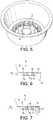
- FIGs 6 and 7explain the principle of the pressure-responsive opening of the cartridge and the liquid flow in the cartridge of the invention after opening of the membrane.
- the membrane 8 of the cartridgeis intact and the internal pressure in the chamber 9 is insufficient to puncture the membrane 8 against the puncturing protrusions 13.
- the membranestarts deforming against the protrusions 13 of the puncture structure.
- Waterneeds to fill the chamber 9 entirely to create an overpressure sufficient to press the membrane against the protrusions until the tensile strength of the material of the membrane is reached.
- the protrusionscan be designed that breaking of the membrane on these protrusions is controlled after the food ingredients have sufficiently dissolved or dispersed in water. For instance, breaking of the membrane may occur at about 2.5 bars of pressure in the chamber.
- the membranemay be an aluminium or a plastic membrane such as thin polypropylene.
- FIG. 7shows the membrane 8 being punctured against the protrusions 13. It is apparent also that the membrane remains supported on the support structure, in particular, by the portions of ridges 17 and the central shield disc 14. As the membrane is punctured, openings are created between the torn surface of the membrane and the surface of the puncturing protrusions. The crossed shaped section of the puncturing protrusions promotes draining of the liquid along the surface of the protrusions. Therefore, the liquid enters the collecting area 5 in a substantially axial direction (as illustrated by direction "A") across the membrane and in as many passages as perforations have created in the membrane. The liquid then transversally flows through the collected area up to the outlet 15 in the radial direction (as illustrated by direction "B").
- the liquidis not solicited to form jets but on the contrary is dampened by the support or distancing structure 12 which is positioned between the openings created in the membrane by the puncturing protrusions and the central outlet in the collecting area.
- the support or distancing structure 12which is positioned between the openings created in the membrane by the puncturing protrusions and the central outlet in the collecting area.
- the liquidis given a tortuous path through the collecting area thereby liquid velocity is significantly lowered.
- Liquidis then passed through predefined openings 41 provided in the outlet where it can thus be guided transversally through the tubular portion 6.
- the legs 16 in the outletfurther provide dampening of the flow by offering a physical barrier transversal to the direction B of the flow in the collecting area and by splitting the liquid flow into different streams in the tubular portion.
- the tubular portion 6extends in an axial direction causing again the liquid to slow down before it is dispensed in a receptacle.
- a means for guiding the flowsuch as transverse ribs 16.
- a second possible embodiment of the cartridge of the inventionis illustrated in relation to figures 8 to 12 .
- the support structurecomprises a central support surface 140 placed adjacent to a series of outlets 150.
- the outlets 150are provided in the bottom 40 of the cup. They can be positioned along a substantially circular pattern around the centre of the collecting area. For example, eight small outlets are provided.
- the support surface 140is placed at a distance above the entry side of the outlets.
- the surface 140further preferably extends outwardly by small legs 141 beyond the surface area of each outlet.
- the outletsextend through the bottom of the cup outwardly to a tubular portion 60 for properly guiding the flow of liquid in a privileged direction.
- separating walls 160for example, forming a crossed design in the plane of extension of the transversal section of the tubular portion.
- the puncture structurecan be made by a series of protrusions 130, e.g., of cross-shaped section, distributed in the vicinity of the periphery of the bottom wall.
- the number of protrusionsmay be lower than for the preceding mode.
- the number of protrusioncan be substantially equal to the number of outlets.
- the support structurecan comprise curved portions of ridges 170. They may be arranged in a substantially discontinuous circular or concentric pattern with radial passages 180 formed between the portions of ridges.
- the portions of ridgescan be placed between the protrusions 130 and the outlets 150 to slow the liquid down in the collecting area. Additional portions of ridges 190 can be provided in radial direction relative to the centre of the collecting area and between the protrusions for a more precise tearing of the membrane on the puncture protrusions 130.
- Figures 13 and 14represent a cartridge of the invention into which is introduced a water injection intruding member 80 of a beverage production device.
- the intruding member for the water injection 80 of the deviceis designed to inject water under pressure in the chamber 9 of the cartridge. Water under pressure interacts with the food substance contained in the chamber 9 to produce a food liquid that is dispensed from the cartridge.
- the water injection intruding memberis formed like a hollow needle comprising a piercing tip 82 for piercing the lid or membrane 7 of the cartridge.
- the memberis traversed by a water conduit leading to a water outlet 81 which is oriented in the direction of the central shield wall 14.
- the membercan be off-centred relative to the longitudinal central axis of the cartridge and with an outlet 81 oriented towards the bottom and centre of the cartridge. More precisely, the water outlet 82 forms a water cone or jet 83 which centreline is directed to the central support surface 14.
- the support surface 14forms a reflective surface for the water jet so that: firstly, the delivery membrane 8 cannot be perforated accidentally by the jet under pressure, and secondly, the reflected jets or streams of water 84 provide high turbulence in the chamber which is prone to improve the interaction between water and the substance in the chamber. In particular, an effect of vortex can be obtained in the chamber which proves to be particularly efficient for the dissolution of soluble food ingredients such as fat and/or protein based ingredients.
- Figures 15 and 16represent a another possible configuration of the system with the water injection member 800 being centrally placed.
- the injection member 800comprises a sharp tip 820 for piercing the lid and allowing the introduction of an injection part of the member in the chamber of the cartridge.
- the injection member 800comprises a central needle with a straight internal water conduit ending by an outlet 810 directing the fluid in the direction of the central axis of the cartridge towards the support surface 14. Therefore, the outlet 810 is arranged in such manner that a jet of water 830 is provided under pressure from the member to the bottom of the cartridge which hits the membrane at the location of the support surface 14.
- Incident jets 840are provided which create a turbulent flow of liquid in the chamber and promotes dissolution of the ingredients. There is no pressurized jet of liquid being able to flow directly through the delivery wall to the outlet 15 of the cartridge because the outlet is protected by the shield surface 14.
- More than one injection membercan be envisaged.
- the same configuration of the systemis applicable to the cartridge of figures 8 to 12 with the direction of the water jet(s) to the supportive surface 140.
- the cartridgecomprises a lid 7 having a substantially rigid wall 70 sealed onto the edge of the cup.
- a small number of jet-forming orifices 71are formed, preferably one or two, through the wall 70. Each orifice is preferably placed in location which is not aligned with the central axis "O" of the capsule so that a higher fluid turbulence is provided in the cartridge.
- the lidfurther comprises a protective cover 72 sealed onto the wall 70 and which can be pierceable or peelable.
- the cartridgecomprises a lid 7 having a rigid wall 70 in which a small number of orifices are created which are oriented in a direction of the support surface 140. As a result, the jet of liquid can reflect towards the interior of the cartridge without the risk of perforating the puncturable delivery wall 8.
- the lidmay also comprise a protective cover 72.
- the ingredientmay be an ingredient that does not dissolve but is brewed such as tea leaves or ground coffee.
Landscapes
- Engineering & Computer Science (AREA)
- Mechanical Engineering (AREA)
- Apparatus For Making Beverages (AREA)
- Package Specialized In Special Use (AREA)
- Infusion, Injection, And Reservoir Apparatuses (AREA)
- Devices For Dispensing Beverages (AREA)
- Containers And Packaging Bodies Having A Special Means To Remove Contents (AREA)
Description
- The present invention relates to a single-use cartridge containing an ingredient intended to interact with an amount of water injected in the cartridge for preparing a liquid. The cartridge is typically used for preparing liquid food such as a nutritional liquid preparation, e.g., an infant formula, a soup or a beverage. The cartridge is typically inserted in a dispensing machine adapted for receiving the cartridge, for injecting water at a suitable temperature and therefore preparing quickly, hygienically and conveniently a liquid food from said cartridge.
- A cartridge for preparing liquid food in a dispensing machine, such as an in-home delivery system, is known for example in
WO 03/059778 - For certain ingredients, it is important to allow a sufficient interaction between water and the ingredients in the cartridge, e.g., mixing, brewing or dilution, and to avoid water preferred flow path that could traverse the substance and leave dry portions of ingredients, e.g. food powder, which are not wetted by water. A delayed opening of the delivery wall of the ingredient's chamber of the cartridge ensures that the largest amount of ingredient is wetted before the liquid can leave the cartridge. This delayed opening provides a way to reduce the preferred flow shortcut through the substance. It also ensures a full dissolution of the substance when this one is soluble. Indeed, for certain ingredients, it is necessary to obtain a complete dissolution of the substance in the chamber before the liquid can be released. It means that opening must occur when the chamber is entirely filled and mixed with the ingredient and a liquid mixture is obtained. If the membrane opens too early, dry ingredient such as solid lumps may be left in the chamber. This may result in a volume of delivery food liquid that does not reach the required concentration. For certain liquid preparations such as infant formula or other nutritional preparations, a low concentration of the delivered liquid is not acceptable, in particular for persons for which the intake of food and nutrients must be accurately controlled.
- Another problem met with existing cartridges is that the flow of the food liquid must be delivered in a controlled manner. In particular, the flow of liquid must not be blocked, reduced or restricted in some way. This is important for providing a rapid, consistent and hygienic delivery in particular with sensitive food such as infant formulas.
- Also, for certain liquid preparations, a significant amount of foam on the delivered liquid may be not desired because it could provide a too high solid concentration of the final liquid and/or a texture which is not appropriate for its intended use.
- Therefore, the flow of liquid must be delivered in a controlled manner, preferably without risk of blocking, without splashing, therefore, preferably smoothly through the delivery outlet, while still an effective mixing or homogenization can take place in the chamber of the cartridge. This may be contradictory with the need for a certain opening delay in the cartridge to obtain sufficient interaction between water and the substance in the cartridge. Indeed, a delayed opening requires creating a rise of pressure in the chamber till the chamber is opened. When the chamber opens, e.g., the delivery membrane ruptures, the liquid tends to flow as powerful jets through the created openings. In particular, the membrane tends to collapse forming restriction areas which are prone to form high velocity jets in many possible uncontrolled directions.
- Therefore, existing cartridges are not properly designed to provide both a delayed opening allowing a proper interaction between water and the substance, e.g., a proper dissolution or brewing of the ingredient in the cartridge, and a slow and directionally controlled delivery flow that enables a hygienic delivery, such as a direct delivery in the receiving receptacle, i.e., a baby bottle, a cup or glass, with a reduced risk of contamination outside of the receptacle.
WO2005/016094 relates to a coffee or tea pod comprising a spiked pod into which is positioned a lower filter layer and a foiled envelope. The water pressure forces both the lower filter layer and the foiled envelope against the spikes of the spiked pod. The punctures caused by the spikes allow the brewed beverage to pass therethrough while substantially maintaining the brewing material therein. The beverage leaves the pod through a plurality of holes distributed in the bottom of the pod.EP1555218B1 relates to a cartridge for coffee or a soluble substance comprising a container, a lid and a filter designed to be positioned inside the container and above the bottom wall through which the beverage leaves. The bottom wall has a breakable portion designed to break when the liquid inside the cartridge reaches a pre-set pressure so as to form an aperture to allow beverage to be extracted from the cartridge. The breakable portion is obtained by means of grooves formed in a weakened portion of the bottom wall. One problem is that it is relatively difficult to control the resistance of the weakened portion that opens under the sole effect of the pressure of fluid in the cartridge to ensure a reproducible delay of the opening time from cartridge to cartridge. Thus, inconsistent opening times will cause beverages having different solids concentration and thus different quality.EP1580143B1 relates to a cartridge for extracting a beverage from particulate substance contained therein by means of water under pressure, the cartridge comprising a cup portion with a cup port and a lid for closing the cup portion; the base of the cup portion comprising a plurality of ridges directly formed thereon and protruding towards the internal volume of the cartridge and a filter placed on the ridges to define a fine canalization between the filtering means and the cup port. The delayed opening is obtained by means of a slit or orifice valve that opens under an internal pre-set pressure. The filter must be sufficiently thick and rigid enough to resist the pressure and avoid its collapsing in the canalization. A disadvantage is the use of thick plastic material to resist the pressure and the high number of pieces necessary to form the cartridge which makes the cartridge complex and costly to manufacture.WO2007/039032 relates to a cartridge of the same principle as the one ofEP1580143B1 but with a safety cap which is mounted on the external surface of the cup port and partially closes the external open end thereof. DocumentWO2008/087553 discloses a cartridge according to the preamble ofclaim 1.- The present invention aims at improving a cartridge for solving the above-mentioned problems and possibly others. In a general manner, the cartridge of the invention aims at improving the consistency of the flow of the liquid that exits the cartridge and at improving the dissolution or brewing of the substance contained in the cartridge.
- The cartridge of the invention contains a food substance adapted to interact with water injected in the cartridge to produce a food liquid that is dispensed from the cartridge.
- The cartridge comprises:
- a cup having a chamber for holding the food substance and a lid,
- a puncturable delivery wall that holds the substance in the chamber,
- a puncturing structure to puncture at least one opening in the delivery wall as a response of water filling the chamber,
- a collecting area for collecting the liquid passing through the delivery wall; said collecting area being placed downstream the puncturable delivery wall,
- at least one liquid outlet in the collecting area for allowing the liquid to leave the collecting area,
- wherein the cartridge comprises a support structure comprising at least one support surface configured to support at least one portion of the delivery wall to maintain a flow gap between the puncture structure and the at least one outlet.
- Preferably, at least one support surface is arranged in the flow path between the puncturing structure and the at least one outlet and/or is placed above and/or adjacent the at least one outlet.
- Therefore, the cartridge of the invention prevents the membrane from collapsing in the collecting area or from forming blocking areas for the flow and therefore, the cartridge ensures a more regular flow path and a controlled direction of the liquid flow path downstream of the punctured membrane. The flow path may also be controlled to change direction in such a way that it can slow down sufficiently and can be released in a smoother way.
- In a mode, the support structure is placed between the puncturable delivery wall and the bottom wall of the cup forming the collecting area.
- The support structure is preferably connected to the bottom wall of the cup. It can be integral to the bottom wall and extending therefrom.
- The puncturing structure is also preferably connected to the bottom wall, most preferably, this structure is an integral part of the bottom wall of the cartridge.
- In order to provide a more homogeneous flow of the liquid delivered out of the cartridge, the cartridge can comprise a series of outlets. The outlets are preferably placed or gathered in or closed to the centre of the collecting area. The number of outlets may vary. For instance, the number of outlets may be between 1 and 10. The outlet can also be a flow guiding duct extending from the outlet(s). The outlets may be placed circumferentially around the guiding duct to collect the liquid flowing transversally from the collecting area.
- In particular, at least one support surface of the support structure forms a portion of disc or a dome that extends transversally beyond the outlet or the series of outlets. The small portion of disc or dome is preferably larger than or substantially equal to the largest transversal dimension of the outlet or the series of outlets. As a result, the delivery wall can be properly supported by the support structure and there is a lower risk that outlets become blocked by a flexible collapsing wall, e.g., a membrane, due to the pressure of liquid in the cartridge. The outlet(s) can so be maintained with a defined opening surface area, with a reduced risk of possible restriction formed by a deformed part of the delivery wall. The liquid outlet(s) is (are) thus neither blocked nor restricted by the delivery wall. The portion of disc preferentially may be a flat or slightly convex upper surface to support the delivery wall without risk of rupture of it.
- According to an aspect of the invention, the support structure comprises portions of ridges placed in the flow path between the puncturing means and the at least one outlet. The portions of ridges are placed concentrically around the liquid outlet(s), with flow passages in-between, for breaking the flow of liquid towards the outlet. The portion of ridges may take different forms and dimensions. The portions of ridges provide support but also may break the flow of liquid towards the outlet(s).
- For example, the portions of ridges can radially surround the outlet, and be placed at a radial distance from the outlet. Hence, the portions of ridges form a concentric discontinuous pattern to provide the flow with a tortuous slowing down path toward the outlet. For this, the portions of ridges delimit a series of circumferential channels and of radial passages between the ridges for the liquid to be slowed down and guided toward the outlet(s).
- The puncturing structure may form a plurality of small protrusions. The protrusions have a sufficiently sharp edge or tip to perforate the puncturable wall when the wall is pressed thereon by the effect of the pressure that builds in the cartridge. Hence, the puncture structure may comprise puncture surfaces of smaller width or section than the width or section of the support surface of support structure. Therefore, the puncturable wall will resist to perforation on the support structure thus creating suitable gaps for flow path toward the outlets whereas it will perforate by relatively defined openings against the protrusions of the puncturing structure.
- The protrusions can be arranged concentrically around the outlet(s). Therefore, different streams of liquid flow are created through the delivery wall of the chamber to ensure also a proper circulation of water through the substance in the chamber as well as a homogeneous flow of liquid which collects in the collecting area.
- The protrusions of the puncturing structure may be formed of a plurality of a sharp puncturing forms like crosses, cones or blades. In a preferred configuration, the protrusions form crosses in their transversal section.
- The support structure further comprises portions of ridges placed in a radial direction of the bottom surface of the cup. The radially oriented portions of ridge can provide an additional support of the delivery wall, in particular, when placed between the protrusions. Therefore, the wall is prevented from collapsing between the protrusions. Hence, the liquid is better guided in the collecting areas.
- According to a preferred example, the cup is an injected plastic member such as in polypropylene or any other suitable food grade plastic material. The delivery wall is preferably a flexible membrane made of aluminium and/or polymer. The delivery wall can be sealed on an inner annular step portion provided in the cup. The delivery wall can remain unsealed onto the support structure as the pressure. The cup is further sealed by a puncturable membrane forming the lid of the cartridge.
- In a mode, the lid of the cartridge comprises at least one injection orifice of small size for forming a jet of the liquid entering the chamber containing the food substance. The at least one injection orifice has preferably a diameter of less than 1.0 mm, most preferably comprised between 0.4 and 0.8 mm. Such small sizes of the orifice generate high momentum of the liquid in the cartridge and therefore enhance the dissolution or dispersion of the substance, in particular, fat and protein powder. The at least one injection orifice is preferably placed in a location which is not axially aligned, i.e., off-centred, relative to the centreline of the cartridge. In a mode, the number of orifices is low, preferably, less than 5, most preferably one or two orifices are formed in the lid.
- The lid can further comprise a protective cover placed externally of an under-layer of the lid comprising the jet-forming orifice(s), for ensuring protection of the substance contained in the chamber before use of the cartridge. Such protective cover can be a peel-off or a puncturable membrane for instance.
- In a first mode, the injection orifice is configured to orient a jet of liquid in a direction which is substantially normal to the puncturable delivery wall. In the terms "substantially normal direction", it is meant that the configuration of the jet of liquid is not of more than 10 degrees from the normal to the delivery wall.
- In another possible mode, the injection orifice is configured to orient a jet towards the support surface of the support structure configured to support the delivery wall.
- In another aspect of the invention, a cartridge system is proposed which comprises:
a cartridge and a beverage production device for holding said cartridge and comprising a water injection intruding member. - The water injection intruding member of the device is designed to inject water in the cartridge under pressure for interacting with a food to produce a food liquid that is dispensed from the cartridge. The cartridge comprises a cup having a chamber for holding the food substance, a lid and a delivery wall puncturable by the water injection intruding member that holds the substance in the chamber, a puncturing structure to puncture at least one opening in the delivery wall as a response of water filling the chamber, a collecting area for collecting the liquid passing through the delivery wall in a substantially axial direction. The collecting is placed downstream the puncturable delivery wall. At least one liquid outlet in the collecting area for allowing the liquid to leave the collecting area. The cartridge comprises a support structure comprising at least one support surface configured to support at least one portion of the delivery wall and wherein the water injection intruding member is configured to inject water in the cartridge under pressure in a direction focused towards said support surface.
- Such a configuration of the water injecting means relative to the cartridge ensures that the delivery wall is not pierced accidentally at a non-desired point and it also provides an improved mixing of water in the chamber of the cartridge by promoting reflections of the water jet in the chamber. In particular, the water injection intruding member is so arranged that the water jet hits the delivery wall which is supported by the membrane. Therefore, since the wall is supported by the support surface underneath, the water jet does not perforate the wall due to the localized water pressure on the wall, e.g., an aluminium or plastic membrane. The water jet is further diverted in the direction of the chamber and can create a vortex in the chamber that promotes an improved interaction between water and the substance, e.g., a good mixing.
- The delivery wall can be a puncturable membrane that is gastight for opening under pressure against the puncture structure, such as an aluminium membrane or a non-porous polymer such as PP.
- Alternatively the delivery wall can be a filter such as a paper filter or a porous filter membrane. The filter is supported by the support structure for resisting to the pressure in the chamber without tearing and/or collapsing and closing the flow gap in the collecting area. The delivery wall can be formed by the superposition of both a puncturable non-porous membrane and a filter.
- In a first possible mode, the water injection intruding member has a piercing tip for being able to perforate the lid. The member has a water outlet which is arranged to direct at least one jet of water in the direction towards the support surface of the cartridge. Preferably, the direction is towards the centre of the cartridge. The water outlet may be designed to provide a fan spray of waterforming a cone which centreline is directed towards the support surface.
- The water injection intruding member can be located in an off-centred location relative to the centre of the cartridge. The water injection intruding member can also be aligned axially in the centre of the cartridge. More than one water injection intruding members can enter the cartridge at different locations.
- In one mode, the cartridge has a support surface which is transversally oriented to the longitudinal axis of the cartridge and the water injection intruding member is off-centred relative to said axis.
- In another mode, the cartridge has a support surface which is transversally oriented to the longitudinal axis of the cartridge and the water injection intruding member is aligned with said axis.
- In another aspect, the invention relates to a cartridge system comprising:
- a cartridge and a beverage production device for holding said cartridge and,
- water injection means; wherein the cartridge contains a food substance adapted to interact with water injected through the water injection means in the cartridge and to produce a food liquid that is dispensed from the cartridge;
- said cartridge comprising:
- a cup having a chamber for holding the food substance and a lid,
- a delivery wall that holds the substance in the chamber,
- a puncturing structure to puncture at least one opening in the delivery wall as a response of water filling the chamber,
- a collecting area for collecting the liquid passing through the delivery wall in a substantially axial direction; said collecting area being placed downstream the puncturable delivery wall,
- at least one liquid outlet in the collecting area for allowing the liquid to leave the collecting area,
- wherein the cartridge comprises a support structure comprising at least one support surface configured to support at least one portion of the delivery wall and wherein the water injection means are configured to inject water in the chamber under pressure in the form of at least one jet.
- In a first possible mode, the water injection means comprises a water injection intruding member of the beverage production device as aforementioned.
- In an alternative mode, the water injection means comprises a lid of the cartridge comprising at least one small orifice configured to form a high-momentum jet of liquid (i.e., water) in the chamber as aforementioned. The jet-forming orifices can be oriented in a direction normal to the puncturable delivery wall of the cartridge or alternatively be inclined towards the support surface of the support structure.
- Further features of the present invention will be described in more detail in the following description in which:
Figure 1 is a side view of a cartridge of the invention according to a first embodiment;Figure 2 is a cross sectional view of the cartridge offigure 1 ;Figure 3 is a top view of the cup of the cartridge offigures 1 and 2 ;Figure 4 is a bottom view of the cup of cartridge offigures 1 and 2 ;Figure 5 is an upper perspective view of the cup of the cartridge offigures 1 and 2 ;Figure 6 is a schematic view showing a detail of the cartridge for the embodiments offigures 1 to 4 before puncturing of the membrane;Figure 7 is a schematic view similar tofigure 6 after puncturing of the membrane;Figure 8 is a cross sectional view of the cartridge offigure 1 according to a second embodiment;Figure 9 is a detail of the view offigure 8 ;Figure 10 is a top view of the cup of the cartridge offigures 8 and 9 ;Figure 11 is an upper perspective view of the cup of the cartridge according to the second embodiment;Figure 12 is a bottom view of the cup of the cartridge according to the second embodiment;Figure 13 is a cross sectional view of the cartridge offigure 2 associated to a water injection device of a beverage preparation device;Figure 14 is a top view of the cup of the cartridge (without its top membrane) offigure 2 showing the water injection device from the top;Figure 15 is a cross sectional view of the cartridge offigure 2 associated to another embodiment of water injection device of a beverage preparation device;Figure 16 is a top view of the cup of the cartridge (without its top membrane) showing the water injection device offigure 15 from the top;Figure 18 is a cross sectional view of a variant of the cartridge offigure 8 in which the lid of the capsule comprises at least one jet-forming orifice oriented perpendicularly to the puncturable delivery wall;- Figure 19 is a cross sectional view of another variant of the cartridge of
figure 8 . - A cartridge of the present invention in a first mode is illustrated in
figures 1 to 7 . Thecartridge 1 comprises acup 2 preferably made of plastics. Suitable thermoplastics can be polypropylene or a multi-layer of polypropylene layers and a gas barrier layer such as EVOH. A possible multi-layer can be PP-EVOH-PP. The cup is preferably obtained by injection in one piece. The cup comprises amain body portion 3, a steppedportion 4 andcollection area 5 and atubular outlet portion 6. - At the upper end of the cartridge, an
upper side edge 20 protrudes outwards forming a sealing area for alid 7. Thelid 7 can be a flexible membrane which forms the water injection side of the cartridge. Injection of water is typically performed by piercing the membrane at one or several points in the membrane by means of a perforating system of a beverage preparation machine (not shown). The membrane can be typically made of a thin laminate of aluminium and/or polymers. For instance, the membrane comprises a laminate of PET and a gas barrier layer such as EVOH. - In an alternative, the
membrane lid 7 may be peelable and so removed before insertion in the food preparation machine. In this case, the machine may be designed to cover in a water-tight arrangement the upper side of the cartridge by an injection shower applying a fluid-tight pressure on theupper edge 20 of the cup. In another alternative (not shown), the lid is a thicker wall comprising premade injection openings for distributing water in the cartridge. - Inside the cup of the cartridge is placed a flexible
puncturable delivery wall 8, e.g., a second membrane. The membrane can be welded onto a peripheralinternal edge 42 of the cup. The first andsecond membranes closed chamber 9 that contains afood substance 10, e.g., a dose of soluble nutritional ingredients. The chamber can be gastight, substantially oxygen free and be filled by a protective gas such as nitrogen in order to protect thesubstance 10. For example, the membranes can be made of a material such as aluminium for which the puncture resistance can be precisely controlled and which also provides a suitable tightness to gas. For example, theinternal membrane 8 can be made of thin aluminium, for example, of between 10 and 100 microns. The volume for thechamber 9 may vary depending on the type of ingredient and the liquid food to be delivered. For instance, the volume may vary from 25 to 100 cc, preferably between 30 to 70 cc. - At the bottom of the
cup 2 is placed amembrane puncturing structure 11. The membrane puncturing structure is designed to puncture a plurality of perforations in the membrane when a threshold of pressure inside the chamber is reached as water fills the chamber. According to an aspect of the invention, themembrane puncturing system 11 is designed to enable a delayed opening of theflexible delivery wall 8, i.e., puncturing of the membrane, so that the chamber has the time to be entirely filled with water and dissolution of the ingredient is carried out entirely in the chamber with as little solid, preferably no solid, as possible left in the chamber. The puncturing structure is associated to a support or distancingstructure 12 which role is to maintain a flow path gap in the liquid collecting area and to avoid collapsing of the membrane when the membrane is punctured. The support structure is placed transversally or radially between the outlet and the puncturing structure. - In
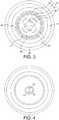
figures 3 and 4 are shown a possible design of the puncturing and support structures. First of all, the puncturing structure comprises puncturingelements 13 in the form of cross-shaped protrusions which are located in thebottom wall 40 of the collecting area. Theelements 13 are preferably made integral with thebottom wall 40. Themembrane 8 ruptures when it is pressed, under the effect of the internal pressure in thechamber 9, onto the edges of a cross-shaped protrusions of the puncturing structure. The cross-shaped protrusions are used to tear the membrane and create a plurality of small perforations. The perforations as obtained by the circular distribution of theprotrusions 13 are thus preferably created in a substantially circular pattern around and at a certain distance of the outlet. - Instead of cross-shaped protrusions, sharp puncturing forms like cones or blades, could be used to provide smaller or more defined perforations in the membrane. The number of these puncturing protrusions may vary from 5 to 20, for example. These protrusions have mainly a perforating role for the membrane that is pressed against.
- Secondly, a
support structure 12 is provided that comprises acentral shield wall 14 having the form of a disc that covers theliquid outlet 15. This shield wall extends transversally to form a support for the membrane that deforms in the axial direction due to the pressure of liquid in the chamber. The shield wall is connected to the bottom surface of the collecting area bylegs 16 delimiting in-between passages oropenings 41 for the liquid to flow in theoutlet 15. - The
support structure 12 may comprise additional elements in relief such as small portions ofridges protrusions 13. In particular, portions ofridges 19 may be placed relatively close to the puncture structure but may be slightly smaller to enable a proper puncturing of the membrane by the puncturing structure. For instance, these portions ofridges 19 may be formed by a continuous circular ridge from which small portions of ridges extend radially to separate eachcross-shaped elements 13. These portions ensure that the membrane does not collapse between each of theprotrusions 13 and therefore ensure a homogeneous collection of the flow through the created perforations in the membrane. On the contrary, between the outlet and the puncturing protrusions, higher portions ofridges ridges Figures 6 and 7 explain the principle of the pressure-responsive opening of the cartridge and the liquid flow in the cartridge of the invention after opening of the membrane. Infigure 6 , themembrane 8 of the cartridge is intact and the internal pressure in thechamber 9 is insufficient to puncture themembrane 8 against the puncturingprotrusions 13. As internal pressure builds up in the chamber the membrane starts deforming against theprotrusions 13 of the puncture structure. Water needs to fill thechamber 9 entirely to create an overpressure sufficient to press the membrane against the protrusions until the tensile strength of the material of the membrane is reached. Hence, the protrusions can be designed that breaking of the membrane on these protrusions is controlled after the food ingredients have sufficiently dissolved or dispersed in water. For instance, breaking of the membrane may occur at about 2.5 bars of pressure in the chamber. The membrane may be an aluminium or a plastic membrane such as thin polypropylene.Figure 7 shows themembrane 8 being punctured against theprotrusions 13. It is apparent also that the membrane remains supported on the support structure, in particular, by the portions ofridges 17 and thecentral shield disc 14. As the membrane is punctured, openings are created between the torn surface of the membrane and the surface of the puncturing protrusions. The crossed shaped section of the puncturing protrusions promotes draining of the liquid along the surface of the protrusions. Therefore, the liquid enters the collectingarea 5 in a substantially axial direction (as illustrated by direction "A") across the membrane and in as many passages as perforations have created in the membrane. The liquid then transversally flows through the collected area up to theoutlet 15 in the radial direction (as illustrated by direction "B"). Thanks to theflow path gap 48 which is maintained in the collecting area, the liquid is not solicited to form jets but on the contrary is dampened by the support or distancingstructure 12 which is positioned between the openings created in the membrane by the puncturing protrusions and the central outlet in the collecting area. In particular, as a result of the concentric distribution of the portions ofridges predefined openings 41 provided in the outlet where it can thus be guided transversally through thetubular portion 6. Thelegs 16 in the outlet further provide dampening of the flow by offering a physical barrier transversal to the direction B of the flow in the collecting area and by splitting the liquid flow into different streams in the tubular portion. Thetubular portion 6 extends in an axial direction causing again the liquid to slow down before it is dispensed in a receptacle. In the tubular portion can be placed a means for guiding the flow such astransverse ribs 16.- A second possible embodiment of the cartridge of the invention is illustrated in relation to
figures 8 to 12 . - The difference with the previous embodiment essentially lies in the particular configuration of the
support structure 110 in the centre of the collectingarea 50. In particular, the support structure comprises acentral support surface 140 placed adjacent to a series ofoutlets 150. Theoutlets 150 are provided in the bottom 40 of the cup. They can be positioned along a substantially circular pattern around the centre of the collecting area. For example, eight small outlets are provided. Thesupport surface 140 is placed at a distance above the entry side of the outlets. Thesurface 140 further preferably extends outwardly bysmall legs 141 beyond the surface area of each outlet. Such a configuration ensures that the puncturable wall, e.g.,delivery membrane 8, is correctly supported and does not break or collapse under pressure to block any of theoutlets 150 in the central area. The outlets extend through the bottom of the cup outwardly to atubular portion 60 for properly guiding the flow of liquid in a privileged direction. Inside thetubular portion 60 can be provided separatingwalls 160, for example, forming a crossed design in the plane of extension of the transversal section of the tubular portion. - In the collecting
area 50, the puncture structure can be made by a series ofprotrusions 130, e.g., of cross-shaped section, distributed in the vicinity of the periphery of the bottom wall. The number of protrusions may be lower than for the preceding mode. For instance, the number of protrusion can be substantially equal to the number of outlets. Furthermore, the support structure can comprise curved portions ofridges 170. They may be arranged in a substantially discontinuous circular or concentric pattern withradial passages 180 formed between the portions of ridges. For example, the portions of ridges can be placed between theprotrusions 130 and theoutlets 150 to slow the liquid down in the collecting area. Additional portions ofridges 190 can be provided in radial direction relative to the centre of the collecting area and between the protrusions for a more precise tearing of the membrane on thepuncture protrusions 130. Figures 13 and 14 represent a cartridge of the invention into which is introduced a waterinjection intruding member 80 of a beverage production device. The intruding member for thewater injection 80 of the device is designed to inject water under pressure in thechamber 9 of the cartridge. Water under pressure interacts with the food substance contained in thechamber 9 to produce a food liquid that is dispensed from the cartridge. The water injection intruding member is formed like a hollow needle comprising a piercingtip 82 for piercing the lid ormembrane 7 of the cartridge. The member is traversed by a water conduit leading to awater outlet 81 which is oriented in the direction of thecentral shield wall 14. The member can be off-centred relative to the longitudinal central axis of the cartridge and with anoutlet 81 oriented towards the bottom and centre of the cartridge. More precisely, thewater outlet 82 forms a water cone orjet 83 which centreline is directed to thecentral support surface 14. As a result, thesupport surface 14 forms a reflective surface for the water jet so that: firstly, thedelivery membrane 8 cannot be perforated accidentally by the jet under pressure, and secondly, the reflected jets or streams ofwater 84 provide high turbulence in the chamber which is prone to improve the interaction between water and the substance in the chamber. In particular, an effect of vortex can be obtained in the chamber which proves to be particularly efficient for the dissolution of soluble food ingredients such as fat and/or protein based ingredients.Figures 15 and 16 represent a another possible configuration of the system with thewater injection member 800 being centrally placed. Theinjection member 800 comprises asharp tip 820 for piercing the lid and allowing the introduction of an injection part of the member in the chamber of the cartridge. Theinjection member 800 comprises a central needle with a straight internal water conduit ending by anoutlet 810 directing the fluid in the direction of the central axis of the cartridge towards thesupport surface 14. Therefore, theoutlet 810 is arranged in such manner that a jet ofwater 830 is provided under pressure from the member to the bottom of the cartridge which hits the membrane at the location of thesupport surface 14.Incident jets 840 are provided which create a turbulent flow of liquid in the chamber and promotes dissolution of the ingredients. There is no pressurized jet of liquid being able to flow directly through the delivery wall to theoutlet 15 of the cartridge because the outlet is protected by theshield surface 14.- More than one injection member can be envisaged. The same configuration of the system is applicable to the cartridge of
figures 8 to 12 with the direction of the water jet(s) to thesupportive surface 140. - In the embodiment of
figure 17 , the cartridge comprises alid 7 having a substantiallyrigid wall 70 sealed onto the edge of the cup. A small number of jet-formingorifices 71 are formed, preferably one or two, through thewall 70. Each orifice is preferably placed in location which is not aligned with the central axis "O" of the capsule so that a higher fluid turbulence is provided in the cartridge. The lid further comprises aprotective cover 72 sealed onto thewall 70 and which can be pierceable or peelable. In the embodiment offigure 18 , the cartridge comprises alid 7 having arigid wall 70 in which a small number of orifices are created which are oriented in a direction of thesupport surface 140. As a result, the jet of liquid can reflect towards the interior of the cartridge without the risk of perforating thepuncturable delivery wall 8. The lid may also comprise aprotective cover 72. - The present invention, as defined by the claims, has been described in relation to different embodiments as a matter of example. However, other examples are possible as well as combinations of the presently described examples. For example, the ingredient may be an ingredient that does not dissolve but is brewed such as tea leaves or ground coffee.
Claims (15)
- A cartridge (1) containing a food substance (10) adapted to interact with water injected in the cartridge to produce a food liquid that is dispensed from the cartridge comprising:a cup (2) having a chamber (9) for holding the food substance and a lid,a puncturable delivery wall (8) that holds the substance in the chamber,a puncturing structure (13, 130) to puncture at least one opening in the delivery wall as a response of water filling the chamber,a collecting area (5, 50) for collecting the liquid passing through the delivery wall in a substantially axial direction; said collecting area being placed downstream the puncturable delivery wall,at least one liquid outlet (15, 150) in the collecting area for allowing the liquid to leave the collecting area,wherein the cartridge comprises a support structure comprising at least one support surface (14, 140) configured to support at least one portion of the delivery wall (8) to maintain a flow gap between the puncture structure and the at least one outlet,wherein the at least one support surface (14, 140) is arranged in the flow path between the puncturing structure (13, 130) and the at least one outlet,characterised in that the cartridge comprises no sealing film welded to the webs of a labyrinth structure of a labyrinth plate in the first half of the radius of the labyrinth plate of the cartridge.
- Cartridge according to claim 1,characterized in that a support surface (14, 140) is further placed above and/or adjacent the at least one outlet.
- Cartridge according to claims 1 or 2,characterized in that the support structure is placed between the puncturable delivery wall (8) and the bottom wall (40) of the cup forming the collecting area.
- Cartridge according to claims 3,characterized in that the support structure (14, 140) is integral to the bottom wall of the cup.
- Cartridge according to any of the preceding claims,characterized in that it comprises a series of outlets (150) placed in the centre of the collecting area.
- Cartridge according to claim 5,characterized in that at least one support surface forms a portion of disc or a dome that extends transversally beyond the series of outlets.
- Cartridge according to any of the preceding claims,characterized in that the support structure comprises portions of ridges (17, 18, 19) placed in the flow path between the puncturing means and the at least one outlet.
- Cartridge according to claim 7,characterized in that the portions of ridges are placed concentrically around the liquid outlet (15) with flow passages in-between for breaking the flow of liquid towards the outlet.
- Cartridge according to claim 7,characterized in that the puncturing structure (13, 130) forms a plurality of small protrusions.
- Cartridge according to claim 9,characterized in that the protrusions are arranged concentrically around the outlet(s).
- Cartridge according to claims 9 or 10, wherein the puncture structure comprises puncture surfaces of smaller width or section than the width or section of the support surface (14, 140) of support structure.
- Cartridge according to any of the preceding claims,characterized in that the puncturing structure (13, 130) comprises a plurality of a sharp puncturing forms like crosses, cones or blades.
- Cartridge according to any one of the preceding claims,characterized in that the support structure further comprises portions of ridges (18) placed in a radial direction of the bottom surface of the cup.
- Cartridge according to any one of the preceding claims,characterized in that the lid comprises at least one injection orifice (71) of small size for forming a jet of the liquid entering the chamber containing the food substance.
- A cartridge system comprising:a cartridge (1) according to any of the preceding claims and a beverage production device for holding said cartridge and,water injection means; wherein the cartridge contains a food substance adapted to interact with water injected through the water injection means in the cartridge and to produce a food liquid that is dispensed from the cartridge; wherein the water injection means are configured to inject water in the chamber (9) under pressure in the form of at least one jet.
Priority Applications (2)
| Application Number | Priority Date | Filing Date | Title |
|---|---|---|---|
| PL09722021TPL2254810T3 (en) | 2008-03-18 | 2009-03-16 | Cartridge for preparation of a liquid comprising puncturable delivery wall |
| EP09722021.4AEP2254810B1 (en) | 2008-03-18 | 2009-03-16 | Cartridge for preparation of a liquid comprising puncturable delivery wall |
Applications Claiming Priority (3)
| Application Number | Priority Date | Filing Date | Title |
|---|---|---|---|
| EP08152871 | 2008-03-18 | ||
| PCT/EP2009/053033WO2009115475A1 (en) | 2008-03-18 | 2009-03-16 | Cartridge for preparation of a liquid comprising puncturable delivery wall |
| EP09722021.4AEP2254810B1 (en) | 2008-03-18 | 2009-03-16 | Cartridge for preparation of a liquid comprising puncturable delivery wall |
Publications (2)
| Publication Number | Publication Date |
|---|---|
| EP2254810A1 EP2254810A1 (en) | 2010-12-01 |
| EP2254810B1true EP2254810B1 (en) | 2018-12-19 |
Family
ID=39529362
Family Applications (1)
| Application Number | Title | Priority Date | Filing Date |
|---|---|---|---|
| EP09722021.4ANot-in-forceEP2254810B1 (en) | 2008-03-18 | 2009-03-16 | Cartridge for preparation of a liquid comprising puncturable delivery wall |
Country Status (15)
| Country | Link |
|---|---|
| US (1) | US8960076B2 (en) |
| EP (1) | EP2254810B1 (en) |
| JP (1) | JP2011515134A (en) |
| CN (1) | CN101977827B (en) |
| AU (1) | AU2009226916B2 (en) |
| BR (1) | BRPI0908972A2 (en) |
| CA (1) | CA2716610A1 (en) |
| ES (1) | ES2709667T3 (en) |
| MX (1) | MX347270B (en) |
| MY (1) | MY155631A (en) |
| PL (1) | PL2254810T3 (en) |
| RU (1) | RU2487067C2 (en) |
| SG (1) | SG188913A1 (en) |
| UA (1) | UA103315C2 (en) |
| WO (1) | WO2009115475A1 (en) |
Cited By (1)
| Publication number | Priority date | Publication date | Assignee | Title |
|---|---|---|---|---|
| EP3439988B1 (en) | 2016-04-07 | 2020-01-22 | Société des Produits Nestlé S.A. | Closed capsule with opening means and integral barrier layer |
Families Citing this family (88)
| Publication number | Priority date | Publication date | Assignee | Title |
|---|---|---|---|---|
| EP1792849A1 (en)* | 2005-12-02 | 2007-06-06 | Tuttoespresso S.p.a. | Pressure beverage cartridge and preparation method |
| US10722066B2 (en)* | 2010-12-04 | 2020-07-28 | Adrian Rivera | Windowed single serving brewing material holder |
| US11832755B2 (en)* | 2007-07-13 | 2023-12-05 | Adrian Rivera | Brewing material container for a beverage brewer |
| PT2236437E (en) | 2009-03-31 | 2012-04-13 | Nestec Sa | Capsule with filter for preparing a liquid nutritional or food composition and related beverage production system |
| SG175793A1 (en) | 2009-05-05 | 2011-12-29 | Nestec Sa | Capsule for preparing a nutritional product including a filter |
| SA110310345B1 (en) | 2009-05-05 | 2013-12-30 | Nestec Sa | Capsule for Preparing a Nutritional Product Including a Water Filter |
| WO2010128051A1 (en) | 2009-05-05 | 2010-11-11 | Nestec S.A. | Capsule for preparing a nutritional product including a filter and method |
| GB2481068B (en) | 2010-06-11 | 2012-06-20 | Kraft Foods R & D Inc | Cartridge for the preparation of beverages |
| IT1400830B1 (en)* | 2010-06-24 | 2013-07-02 | Torrefazione Ionia S P A | CAP FOR COFFEE MACHINE OR SIMILAR, CONTAINING DRINKING INGREDIENTS SUCH AS COFFEE OR SIMILAR |
| US10071851B2 (en) | 2010-07-12 | 2018-09-11 | Robert Bao Vu | Apparatus and products for producing beverages, and methods for making and using same |
| SMT201900157T1 (en) | 2010-07-22 | 2019-05-10 | K Fee System Gmbh | Portion capsule having an identifier |
| US20130180409A1 (en) | 2010-09-15 | 2013-07-18 | Nestec S.A. | Capsule with enhanced product delivery system |
| US9155418B2 (en)* | 2010-11-15 | 2015-10-13 | Conair Corporation | Brewed beverage appliance and method |
| US8573115B2 (en)* | 2010-11-15 | 2013-11-05 | Conair Corporation | Brewed beverage appliance and method |
| US8950315B2 (en)* | 2010-11-15 | 2015-02-10 | Conair Corporation | Brewed beverage appliance and method |
| USD694620S1 (en) | 2011-03-08 | 2013-12-03 | Kraft Foods R&D, Inc. | Beverage cartridge |
| GB2488799A (en) | 2011-03-08 | 2012-09-12 | Kraft Foods R & D Inc | Drinks Pod without Piercing of Outer Shell |
| GB2489409B (en) | 2011-03-23 | 2013-05-15 | Kraft Foods R & D Inc | A capsule and a system for, and a method of, preparing a beverage |
| CN102166096B (en)* | 2011-04-10 | 2012-11-21 | 九阳股份有限公司 | Beverage preparation method |
| GB2491154B (en) | 2011-05-24 | 2013-07-10 | Kraft Foods R & D Inc | Beverage/food product preparation systems |
| EP2543289A1 (en)* | 2011-07-08 | 2013-01-09 | Koninklijke Philips Electronics N.V. | Device for preparing a beverage |
| EP2559636A1 (en) | 2011-08-19 | 2013-02-20 | Nestec S.A. | An in-mould labelled capsule for beverage preparation |
| WO2013066154A1 (en)* | 2011-08-30 | 2013-05-10 | Biserkon Holdings Ltd. | Capsule, device and method for preparing a beverage by extraction |
| CN102700853B (en)* | 2012-05-25 | 2015-04-29 | 九阳股份有限公司 | Bean powder material package, method and device for manufacturing soyabean milk |
| CN102491006B (en)* | 2011-11-25 | 2014-01-08 | 九阳股份有限公司 | Bean flour refill bag, soybean milk manufacturing method and equipment for preparing soybean milk |
| ITBO20110693A1 (en)* | 2011-12-06 | 2013-06-07 | Ima Ind Srl | PROCEDURE FOR THE FORMATION OF A DISPOSABLE DRINK FOR DRINKS AND CAPSUES SO THEY OBTAINED. |
| AT512630A1 (en)* | 2012-03-09 | 2013-09-15 | Modl | portion capsule |
| CH706369B1 (en)* | 2012-04-04 | 2016-01-15 | Schwanden Kunststoff | Coffee capsule. |
| DE102012105282A1 (en) | 2012-06-18 | 2013-12-19 | K-Fee System Gmbh | Portion capsule and method of making a beverage with a portion capsule |
| DK2877412T3 (en)* | 2012-07-24 | 2017-01-30 | Nestec Sa | CAPS FOR USE IN A FOOD COOKING MACHINE |
| ES2398276B2 (en)* | 2012-08-28 | 2014-09-29 | Cocatech, S.L.U. | Beverage capsule |
| WO2014037341A1 (en)* | 2012-09-05 | 2014-03-13 | Nestec S.A. | A beverage capsule with safety feature |
| USD708057S1 (en) | 2012-09-10 | 2014-07-01 | Kraft Foods R & D, Inc. | Beverage cartridge |
| USD697797S1 (en) | 2012-09-12 | 2014-01-21 | Kraft Foods R&D, Inc. | Beverage cartridge |
| SG11201501783PA (en)* | 2012-10-05 | 2015-05-28 | Nestec Sa | A beverage capsule with spraying-prevention means |
| DE102012223291A1 (en)* | 2012-12-14 | 2014-06-18 | K-Fee System Gmbh | Portion capsule and method of making a beverage with a portion capsule |
| ITPD20120382A1 (en)* | 2012-12-17 | 2014-06-18 | Boutique Del Caffe S R L | AUTOPROTECTED COFFEE CAP WITH FILTER |
| US9783361B2 (en) | 2013-03-14 | 2017-10-10 | Starbucks Corporation | Stretchable beverage cartridges and methods |
| US9657155B2 (en)* | 2013-04-12 | 2017-05-23 | Printpack Illinois, Inc. | Containers and materials with improved punctureability |
| ES2424296B2 (en)* | 2013-05-17 | 2014-11-03 | Cocatech, S.L.U. | Retention and redirection system for beverage preparation capsules |
| ITMI20130906A1 (en)* | 2013-06-03 | 2014-12-04 | Illycaffe Spa | CARTRIDGE FOR DRAWING A BEVERAGE. |
| ITTO20130612A1 (en) | 2013-07-18 | 2013-10-17 | Bisio Progetti Spa | CAPSULE FOR THE PREPARATION OF BEVERAGES WITH INFUSION. |
| USD742221S1 (en)* | 2013-08-13 | 2015-11-03 | Caffitaly System S.P.A. | Capsule for making beverages |
| CH709273A2 (en)* | 2014-02-21 | 2015-08-28 | Delica Ag | Capsule comprising a preferably rotationally symmetrical capsule body. |
| CH709861A1 (en)* | 2014-07-09 | 2016-01-15 | Delica Ag | Capsule comprising a preferably rotationally symmetrical capsule body. |
| CH709296B1 (en)* | 2014-02-21 | 2022-08-15 | Delica Ag | Capsule with a preferably rotationally symmetrical capsule body. |
| CH709570B1 (en)* | 2014-04-29 | 2023-07-31 | Delica Ag | Capsule with a preferably rotationally symmetrical capsule body. |
| US10442610B2 (en) | 2014-03-11 | 2019-10-15 | Starbucks Corporation | Pod-based restrictors and methods |
| CA2947914A1 (en) | 2014-06-10 | 2015-12-17 | Printpack Illinois, Inc. | Containers with improved punctureability |
| GB2527292A (en)* | 2014-06-13 | 2015-12-23 | Kraft Foods R&D Inc | Cartridge for the preparation of beverages |
| JP2017530732A (en)* | 2014-07-16 | 2017-10-19 | イリカフェ エス ピー エー | Cartridge for extracting beverage |
| JP2017531476A (en) | 2014-10-01 | 2017-10-26 | クラフト・フーズ・グループ・ブランズ・エルエルシー | Coffee pod |
| USD757536S1 (en) | 2014-10-01 | 2016-05-31 | Kraft Foods Group Brands Llc | Container |
| US9877495B2 (en) | 2015-01-09 | 2018-01-30 | Starbucks Corporation | Method of making a sweetened soluble beverage product |
| ES2578189B1 (en)* | 2015-01-21 | 2017-06-29 | Segundo PATIÑO PATIÑO | Capsule for the preparation of a drink |
| WO2016135105A1 (en) | 2015-02-27 | 2016-09-01 | K-Fee System Gmbh | Single serve capsule comprising a filter element connected thereto by sealing |
| US10919690B2 (en) | 2015-03-31 | 2021-02-16 | Societe Des Produits Nestle S.A. | Capsule having a membrane and method for preparing a nutritional product |
| ES2791960T3 (en)* | 2015-06-09 | 2020-11-06 | K Fee System Gmbh | Single-dose capsule, system and procedure for the preparation of a drink |
| PT3307647T (en) | 2015-06-10 | 2019-10-28 | K Fee System Gmbh | Capsule with a three layer fleece |
| ES2555631B2 (en)* | 2015-06-26 | 2016-08-09 | Cocatech, S.L.U. | Food beverage preparation capsule with controlled delivery system |
| WO2017009369A1 (en) | 2015-07-13 | 2017-01-19 | K-Fee System Gmbh | Filter element having a cut-out |
| WO2017046352A1 (en) | 2015-09-18 | 2017-03-23 | K-Fee System Gmbh | Adapter for a single serve capsule |
| ITUB20155389A1 (en)* | 2015-11-09 | 2017-05-09 | Sarong Spa | CAPPULE FOR BEVERAGES |
| CN105286641B (en)* | 2015-12-03 | 2019-01-01 | 海口万客食品有限公司 | A kind of capsule preparing beverage |
| JP6885548B2 (en)* | 2016-02-23 | 2021-06-16 | グルッポ ジモカ エス.アール.エル. | Beverage manufacturing capsules |
| ITUA20161349A1 (en)* | 2016-03-04 | 2017-09-04 | Bisio Progetti Spa | Improved capsule for the preparation of infusion and soluble beverages |
| ITUA20161354A1 (en)* | 2016-03-04 | 2017-09-04 | Bisio Progetti Spa | Capsule for the preparation of infusion and soluble drinks |
| ITUA20162114A1 (en)* | 2016-03-30 | 2017-09-30 | Faps Eng Sa | CAPSULE FOR BEVERAGE DISTRIBUTION. |
| CH712695A1 (en) | 2016-07-07 | 2018-01-15 | Mühlemann Ip Gmbh | One-serving pack for making a beverage from a beverage concentrate. |
| EP3484788B1 (en)* | 2016-07-14 | 2020-12-23 | Société des Produits Nestlé S.A. | Coffee capsule for preparing turkish coffee |
| IT201600082459A1 (en)* | 2016-08-04 | 2018-02-04 | Bisio Progetti Spa | Capsule for the preparation of infusion and soluble drinks |
| CN106241081A (en)* | 2016-08-18 | 2016-12-21 | 徐根彪 | Capsule for beverage preparation machine |
| CN106185066A (en)* | 2016-08-18 | 2016-12-07 | 徐根彪 | The beverage preparation machine capsule of side water inlet |
| CA3041722A1 (en) | 2016-11-09 | 2018-05-17 | Pepsico, Inc. | Carbonated beverage makers, methods, and systems |
| IT201700019425A1 (en)* | 2017-02-21 | 2018-08-21 | Bisio Progetti Spa | CAP FOR INFUSION OR SOLUBLE DRINKS EQUIPPED WITH AN ANTI-DROP SYSTEM |
| IT201800003246A1 (en)* | 2018-03-02 | 2019-09-02 | Tecnostampi S R L | CAPSULE FOR CONTAINING A FOOD SUBSTANCE SUITABLE TO INTERACT WITH A PRESSURE FLUID INJECTED INSIDE THE CAPSULE TO OBTAIN A BEVERAGE OUTPUT FROM THE CAPSULE. |
| IT201800003806A1 (en)* | 2018-03-21 | 2019-09-21 | Caffe Borbone S R L | System comprising a flavoring agent |
| US12227323B2 (en) | 2018-07-27 | 2025-02-18 | Gcs German Capsule Solution Gmbh | Method for producing a portion capsule |
| US20200095052A1 (en)* | 2018-09-24 | 2020-03-26 | Nicholas J. Singer | Delivery package for powdered food products |
| KR102576582B1 (en)* | 2018-11-21 | 2023-09-07 | 김인한 | Capsule for preparation of beverage |
| EP3722228A1 (en)* | 2019-04-09 | 2020-10-14 | Frol Explorer Ltd | Capsule and method for preparing and dispensing a viscous drinkable food product |
| ES2788799B2 (en)* | 2019-04-22 | 2022-05-12 | Cocatech S L U | CAPSULE FOR DRINK INFUSION |
| CN111956049A (en)* | 2019-05-20 | 2020-11-20 | 东莞升联五金电器制品有限公司 | Heating equipment and using method thereof |
| ES1235376Y (en)* | 2019-07-09 | 2019-12-18 | Cocatech S L U | DRINK INFUSION CAPSULE |
| US11805934B1 (en)* | 2020-10-21 | 2023-11-07 | Adrian Rivera | Brewing material lid and container for a beverage brewer |
| US12171361B2 (en) | 2020-12-30 | 2024-12-24 | Sharkninja Operating Llc | Hybrid receptacle beverage brewing system |
| USD1048792S1 (en) | 2023-04-12 | 2024-10-29 | Sharkninja Operating Llc | Coffee machine |
| USD1048793S1 (en) | 2023-05-02 | 2024-10-29 | Sharkninja Operating Llc | Coffee machine |
Family Cites Families (16)
| Publication number | Priority date | Publication date | Assignee | Title |
|---|---|---|---|---|
| ATE93373T1 (en)* | 1990-07-27 | 1993-09-15 | Nestle Sa | METHOD FOR BREWING CLOSED PORTION PACKS AND APPARATUS FOR CARRYING OUT THESE METHOD. |
| EP0471094B1 (en)* | 1990-07-27 | 1993-12-01 | Societe Des Produits Nestle S.A. | Insert to be fitted in a cartridge holder |
| TW199884B (en)* | 1991-05-08 | 1993-02-11 | Sociere Des Produits Nestle S A | |
| DK1808382T3 (en)* | 2002-01-16 | 2013-03-25 | Nestle Sa | Closed capsule with a beaker with opening means |
| ITTV20030058A1 (en)* | 2003-04-02 | 2004-10-03 | Hausbrandt Trieste 1892 S P A | SINGLE-DOSE PLASTIC CAPSULES FOR POWDER COFFEE AND SIMILAR. |
| US6948420B2 (en) | 2003-07-22 | 2005-09-27 | The Coca-Cola Company | Coffee and tea pod |
| US8327754B2 (en)* | 2003-07-22 | 2012-12-11 | The Coca-Cola Company | Coffee and tea pod |
| US20060196364A1 (en)* | 2003-07-22 | 2006-09-07 | The Coca-Cola Company | Coffee & Tea Pod |
| ATE529027T1 (en)* | 2003-08-25 | 2011-11-15 | Nestec Sa | METHOD AND DEVICE FOR PRODUCING A BEVERAGE FROM A CAPSULE CONTAINING A SUBSTANCE |
| DK1555218T3 (en) | 2004-02-11 | 2006-10-16 | I T A Ca S R L | coffee Patron |
| WO2005092160A1 (en)* | 2004-03-26 | 2005-10-06 | Illycaffe's.P.A. | Integrated cartridge for extracting a beverage from a particulate substance |
| DK1580143T3 (en)* | 2004-03-26 | 2007-09-24 | Illycaffe Spa | Integrated effort to extract a beverage from a particulate material |
| US20080066623A1 (en)* | 2004-07-07 | 2008-03-20 | Koninklijke Philips Electronics N. V. | Coffee Maker Comprising Means For Creating Turbulence In A Coffee Flow |
| EP1704803A1 (en)* | 2005-03-22 | 2006-09-27 | Tuttoespresso S.p.a. | Beverage cartridge and system |
| ATE428657T1 (en) | 2005-09-21 | 2009-05-15 | Illycaffe Spa | CAPSULE CONTAINING A SUBSTANCE FOR EXTRACTING A DRINK |
| EP1908706B1 (en)* | 2006-06-06 | 2009-12-23 | Nestec S.A. | Capsule with reduced dripping |
- 2009
- 2009-03-16EPEP09722021.4Apatent/EP2254810B1/ennot_activeNot-in-force
- 2009-03-16AUAU2009226916Apatent/AU2009226916B2/ennot_activeCeased
- 2009-03-16MYMYPI2010003944Apatent/MY155631A/enunknown
- 2009-03-16PLPL09722021Tpatent/PL2254810T3/enunknown
- 2009-03-16UAUAA201012138Apatent/UA103315C2/enunknown
- 2009-03-16CACA2716610Apatent/CA2716610A1/ennot_activeAbandoned
- 2009-03-16WOPCT/EP2009/053033patent/WO2009115475A1/enactiveApplication Filing
- 2009-03-16MXMX2010010174Apatent/MX347270B/enactiveIP Right Grant
- 2009-03-16JPJP2011500170Apatent/JP2011515134A/enactivePending
- 2009-03-16RURU2010142298/12Apatent/RU2487067C2/ennot_activeIP Right Cessation
- 2009-03-16BRBRPI0908972-1Apatent/BRPI0908972A2/ennot_activeApplication Discontinuation
- 2009-03-16CNCN2009801097336Apatent/CN101977827B/ennot_activeExpired - Fee Related
- 2009-03-16USUS12/933,286patent/US8960076B2/enactiveActive
- 2009-03-16SGSG2013019716Apatent/SG188913A1/enunknown
- 2009-03-16ESES09722021Tpatent/ES2709667T3/enactiveActive
Non-Patent Citations (1)
| Title |
|---|
| None* |
Cited By (1)
| Publication number | Priority date | Publication date | Assignee | Title |
|---|---|---|---|---|
| EP3439988B1 (en) | 2016-04-07 | 2020-01-22 | Société des Produits Nestlé S.A. | Closed capsule with opening means and integral barrier layer |
Also Published As
| Publication number | Publication date |
|---|---|
| PL2254810T3 (en) | 2019-06-28 |
| AU2009226916B2 (en) | 2014-01-23 |
| CN101977827A (en) | 2011-02-16 |
| MX347270B (en) | 2017-04-20 |
| BRPI0908972A2 (en) | 2015-07-28 |
| CA2716610A1 (en) | 2009-09-24 |
| CN101977827B (en) | 2013-04-17 |
| RU2487067C2 (en) | 2013-07-10 |
| AU2009226916A1 (en) | 2009-09-24 |
| US8960076B2 (en) | 2015-02-24 |
| ES2709667T3 (en) | 2019-04-17 |
| UA103315C2 (en) | 2013-10-10 |
| SG188913A1 (en) | 2013-04-30 |
| EP2254810A1 (en) | 2010-12-01 |
| JP2011515134A (en) | 2011-05-19 |
| RU2010142298A (en) | 2012-04-27 |
| US20110005399A1 (en) | 2011-01-13 |
| MY155631A (en) | 2015-11-13 |
| WO2009115475A1 (en) | 2009-09-24 |
| MX2010010174A (en) | 2011-03-29 |
Similar Documents
| Publication | Publication Date | Title |
|---|---|---|
| EP2254810B1 (en) | Cartridge for preparation of a liquid comprising puncturable delivery wall | |
| EP2891615B1 (en) | Capsule for a beverage maker | |
| ES2365642T3 (en) | CAPSULE WITH FLOW CONTROL AND FILTER ELEMENT. | |
| CA2938352C (en) | Beverage preparation capsules | |
| JP4604031B2 (en) | System and method for dispensing beverages of different foam content from capsules | |
| US9573753B2 (en) | Capsule and method for the preparation of a beverage by centrifugation | |
| EP2442695B1 (en) | Capsule and system for preparing a beverage comprising soluble substance | |
| US20130180409A1 (en) | Capsule with enhanced product delivery system | |
| BRPI0918240B1 (en) | system for producing edible liquid for preparing an edible beverage, and process for preparing an edible liquid | |
| KR20190142320A (en) | Capsules for the preparation of water soluble beverages or infusions in low pressure extraction systems | |
| BR112020005372B1 (en) | CAPSULE FOR PREPARING INFUSION DRINKS | |
| HK1090527B (en) | Methods and assembly for the preparation of a food product | |
| HK1090527A1 (en) | Methods and assembly for the preparation of a food product | |
| BR112020018741B1 (en) | CAPSULE FOR PREPARING INFUSION-PRODUCED BEVERAGES AND CORRESPONDING CAPSULE PRODUCTION METHOD | |
| BR112019019280B1 (en) | CAPSULE FOR PREPARING INFUSION OR SOLUBLE DRINKS IN LOW PRESSURE EXTRACTION SYSTEMS | |
| HK1137401B (en) | Capsule with flow control and filtering member |
Legal Events
| Date | Code | Title | Description |
|---|---|---|---|
| PUAI | Public reference made under article 153(3) epc to a published international application that has entered the european phase | Free format text:ORIGINAL CODE: 0009012 | |
| 17P | Request for examination filed | Effective date:20101018 | |
| AK | Designated contracting states | Kind code of ref document:A1 Designated state(s):AT BE BG CH CY CZ DE DK EE ES FI FR GB GR HR HU IE IS IT LI LT LU LV MC MK MT NL NO PL PT RO SE SI SK TR | |
| AX | Request for extension of the european patent | Extension state:AL BA RS | |
| DAX | Request for extension of the european patent (deleted) | ||
| REG | Reference to a national code | Ref country code:HK Ref legal event code:DE Ref document number:1149734 Country of ref document:HK | |
| GRAP | Despatch of communication of intention to grant a patent | Free format text:ORIGINAL CODE: EPIDOSNIGR1 | |
| INTG | Intention to grant announced | Effective date:20161017 | |
| TPAC | Observations filed by third parties | Free format text:ORIGINAL CODE: EPIDOSNTIPA | |
| STAA | Information on the status of an ep patent application or granted ep patent | Free format text:STATUS: GRANT OF PATENT IS INTENDED | |
| GRAS | Grant fee paid | Free format text:ORIGINAL CODE: EPIDOSNIGR3 | |
| GRAJ | Information related to disapproval of communication of intention to grant by the applicant or resumption of examination proceedings by the epo deleted | Free format text:ORIGINAL CODE: EPIDOSDIGR1 | |
| GRAL | Information related to payment of fee for publishing/printing deleted | Free format text:ORIGINAL CODE: EPIDOSDIGR3 | |
| STAA | Information on the status of an ep patent application or granted ep patent | Free format text:STATUS: REQUEST FOR EXAMINATION WAS MADE | |
| STAA | Information on the status of an ep patent application or granted ep patent | Free format text:STATUS: EXAMINATION IS IN PROGRESS | |
| 17Q | First examination report despatched | Effective date:20161223 | |
| INTC | Intention to grant announced (deleted) | ||
| GRAP | Despatch of communication of intention to grant a patent | Free format text:ORIGINAL CODE: EPIDOSNIGR1 | |
| STAA | Information on the status of an ep patent application or granted ep patent | Free format text:STATUS: GRANT OF PATENT IS INTENDED | |
| INTG | Intention to grant announced | Effective date:20180921 | |
| GRAA | (expected) grant | Free format text:ORIGINAL CODE: 0009210 | |
| STAA | Information on the status of an ep patent application or granted ep patent | Free format text:STATUS: THE PATENT HAS BEEN GRANTED | |
| AK | Designated contracting states | Kind code of ref document:B1 Designated state(s):AT BE BG CH CY CZ DE DK EE ES FI FR GB GR HR HU IE IS IT LI LT LU LV MC MK MT NL NO PL PT RO SE SI SK TR | |
| REG | Reference to a national code | Ref country code:GB Ref legal event code:FG4D | |
| REG | Reference to a national code | Ref country code:CH Ref legal event code:EP | |
| REG | Reference to a national code | Ref country code:IE Ref legal event code:FG4D | |
| REG | Reference to a national code | Ref country code:DE Ref legal event code:R096 Ref document number:602009056270 Country of ref document:DE | |
| REG | Reference to a national code | Ref country code:AT Ref legal event code:REF Ref document number:1078453 Country of ref document:AT Kind code of ref document:T Effective date:20190115 | |
| REG | Reference to a national code | Ref country code:SE Ref legal event code:TRGR | |
| REG | Reference to a national code | Ref country code:ES Ref legal event code:FG2A Ref document number:2709667 Country of ref document:ES Kind code of ref document:T3 Effective date:20190417 | |
| REG | Reference to a national code | Ref country code:NL Ref legal event code:FP | |
| PG25 | Lapsed in a contracting state [announced via postgrant information from national office to epo] | Ref country code:BG Free format text:LAPSE BECAUSE OF FAILURE TO SUBMIT A TRANSLATION OF THE DESCRIPTION OR TO PAY THE FEE WITHIN THE PRESCRIBED TIME-LIMIT Effective date:20190319 Ref country code:NO Free format text:LAPSE BECAUSE OF FAILURE TO SUBMIT A TRANSLATION OF THE DESCRIPTION OR TO PAY THE FEE WITHIN THE PRESCRIBED TIME-LIMIT Effective date:20190319 Ref country code:HR Free format text:LAPSE BECAUSE OF FAILURE TO SUBMIT A TRANSLATION OF THE DESCRIPTION OR TO PAY THE FEE WITHIN THE PRESCRIBED TIME-LIMIT Effective date:20181219 Ref country code:LV Free format text:LAPSE BECAUSE OF FAILURE TO SUBMIT A TRANSLATION OF THE DESCRIPTION OR TO PAY THE FEE WITHIN THE PRESCRIBED TIME-LIMIT Effective date:20181219 Ref country code:FI Free format text:LAPSE BECAUSE OF FAILURE TO SUBMIT A TRANSLATION OF THE DESCRIPTION OR TO PAY THE FEE WITHIN THE PRESCRIBED TIME-LIMIT Effective date:20181219 Ref country code:LT Free format text:LAPSE BECAUSE OF FAILURE TO SUBMIT A TRANSLATION OF THE DESCRIPTION OR TO PAY THE FEE WITHIN THE PRESCRIBED TIME-LIMIT Effective date:20181219 | |
| REG | Reference to a national code | Ref country code:LT Ref legal event code:MG4D | |
| REG | Reference to a national code | Ref country code:AT Ref legal event code:MK05 Ref document number:1078453 Country of ref document:AT Kind code of ref document:T Effective date:20181219 | |
| PG25 | Lapsed in a contracting state [announced via postgrant information from national office to epo] | Ref country code:GR Free format text:LAPSE BECAUSE OF FAILURE TO SUBMIT A TRANSLATION OF THE DESCRIPTION OR TO PAY THE FEE WITHIN THE PRESCRIBED TIME-LIMIT Effective date:20190320 | |
| PGFP | Annual fee paid to national office [announced via postgrant information from national office to epo] | Ref country code:TR Payment date:20190214 Year of fee payment:10 Ref country code:SE Payment date:20190311 Year of fee payment:11 Ref country code:BE Payment date:20190215 Year of fee payment:11 | |
| REG | Reference to a national code | Ref country code:NL Ref legal event code:PD Owner name:SOCIETE DES PRODUITS NESTLE S.A.; CH Free format text:DETAILS ASSIGNMENT: CHANGE OF OWNER(S), MERGE Effective date:20190620 | |
| RAP2 | Party data changed (patent owner data changed or rights of a patent transferred) | Owner name:SOCIETE DES PRODUITS NESTLE S.A. | |
| REG | Reference to a national code | Ref country code:CH Ref legal event code:PCOW | |
| PG25 | Lapsed in a contracting state [announced via postgrant information from national office to epo] | Ref country code:PT Free format text:LAPSE BECAUSE OF FAILURE TO SUBMIT A TRANSLATION OF THE DESCRIPTION OR TO PAY THE FEE WITHIN THE PRESCRIBED TIME-LIMIT Effective date:20190419 Ref country code:CZ Free format text:LAPSE BECAUSE OF FAILURE TO SUBMIT A TRANSLATION OF THE DESCRIPTION OR TO PAY THE FEE WITHIN THE PRESCRIBED TIME-LIMIT Effective date:20181219 | |
| PGFP | Annual fee paid to national office [announced via postgrant information from national office to epo] | Ref country code:ES Payment date:20190401 Year of fee payment:11 Ref country code:PL Payment date:20190130 Year of fee payment:11 | |
| REG | Reference to a national code | Ref country code:GB Ref legal event code:732E Free format text:REGISTERED BETWEEN 20190801 AND 20190807 | |
| PG25 | Lapsed in a contracting state [announced via postgrant information from national office to epo] | Ref country code:IS Free format text:LAPSE BECAUSE OF FAILURE TO SUBMIT A TRANSLATION OF THE DESCRIPTION OR TO PAY THE FEE WITHIN THE PRESCRIBED TIME-LIMIT Effective date:20190419 Ref country code:SK Free format text:LAPSE BECAUSE OF FAILURE TO SUBMIT A TRANSLATION OF THE DESCRIPTION OR TO PAY THE FEE WITHIN THE PRESCRIBED TIME-LIMIT Effective date:20181219 Ref country code:EE Free format text:LAPSE BECAUSE OF FAILURE TO SUBMIT A TRANSLATION OF THE DESCRIPTION OR TO PAY THE FEE WITHIN THE PRESCRIBED TIME-LIMIT Effective date:20181219 Ref country code:RO Free format text:LAPSE BECAUSE OF FAILURE TO SUBMIT A TRANSLATION OF THE DESCRIPTION OR TO PAY THE FEE WITHIN THE PRESCRIBED TIME-LIMIT Effective date:20181219 | |
| REG | Reference to a national code | Ref country code:DE Ref legal event code:R097 Ref document number:602009056270 Country of ref document:DE | |
| PLBE | No opposition filed within time limit | Free format text:ORIGINAL CODE: 0009261 | |
| STAA | Information on the status of an ep patent application or granted ep patent | Free format text:STATUS: NO OPPOSITION FILED WITHIN TIME LIMIT | |
| PG25 | Lapsed in a contracting state [announced via postgrant information from national office to epo] | Ref country code:DK Free format text:LAPSE BECAUSE OF FAILURE TO SUBMIT A TRANSLATION OF THE DESCRIPTION OR TO PAY THE FEE WITHIN THE PRESCRIBED TIME-LIMIT Effective date:20181219 Ref country code:MC Free format text:LAPSE BECAUSE OF FAILURE TO SUBMIT A TRANSLATION OF THE DESCRIPTION OR TO PAY THE FEE WITHIN THE PRESCRIBED TIME-LIMIT Effective date:20181219 Ref country code:AT Free format text:LAPSE BECAUSE OF FAILURE TO SUBMIT A TRANSLATION OF THE DESCRIPTION OR TO PAY THE FEE WITHIN THE PRESCRIBED TIME-LIMIT Effective date:20181219 | |
| 26N | No opposition filed | Effective date:20190920 | |
| REG | Reference to a national code | Ref country code:BE Ref legal event code:PD Owner name:SOCIETE DES PRODUITS NESTLE S.A.; CH Free format text:DETAILS ASSIGNMENT: CHANGE OF OWNER(S), CESSION; FORMER OWNER NAME: NESTEC S.A. Effective date:20190712 | |
| PG25 | Lapsed in a contracting state [announced via postgrant information from national office to epo] | Ref country code:LU Free format text:LAPSE BECAUSE OF NON-PAYMENT OF DUE FEES Effective date:20190316 | |
| PG25 | Lapsed in a contracting state [announced via postgrant information from national office to epo] | Ref country code:IE Free format text:LAPSE BECAUSE OF NON-PAYMENT OF DUE FEES Effective date:20190316 | |
| REG | Reference to a national code | Ref country code:DE Ref legal event code:R082 Ref document number:602009056270 Country of ref document:DE Representative=s name:MITSCHERLICH, PATENT- UND RECHTSANWAELTE PARTM, DE Ref country code:DE Ref legal event code:R081 Ref document number:602009056270 Country of ref document:DE Owner name:SOCIETE DES PRODUITS NESTLE S.A., CH Free format text:FORMER OWNER: NESTEC S.A., VEVEY, CH | |
| PG25 | Lapsed in a contracting state [announced via postgrant information from national office to epo] | Ref country code:SI Free format text:LAPSE BECAUSE OF FAILURE TO SUBMIT A TRANSLATION OF THE DESCRIPTION OR TO PAY THE FEE WITHIN THE PRESCRIBED TIME-LIMIT Effective date:20181219 | |
| PG25 | Lapsed in a contracting state [announced via postgrant information from national office to epo] | Ref country code:TR Free format text:LAPSE BECAUSE OF FAILURE TO SUBMIT A TRANSLATION OF THE DESCRIPTION OR TO PAY THE FEE WITHIN THE PRESCRIBED TIME-LIMIT Effective date:20181219 | |
| PGFP | Annual fee paid to national office [announced via postgrant information from national office to epo] | Ref country code:DE Payment date:20200303 Year of fee payment:12 Ref country code:IT Payment date:20200221 Year of fee payment:12 | |
| PGFP | Annual fee paid to national office [announced via postgrant information from national office to epo] | Ref country code:CH Payment date:20200313 Year of fee payment:12 | |
| PG25 | Lapsed in a contracting state [announced via postgrant information from national office to epo] | Ref country code:MT Free format text:LAPSE BECAUSE OF NON-PAYMENT OF DUE FEES Effective date:20190316 | |
| PGFP | Annual fee paid to national office [announced via postgrant information from national office to epo] | Ref country code:FR Payment date:20200214 Year of fee payment:12 | |
| REG | Reference to a national code | Ref country code:HK Ref legal event code:WD Ref document number:1149734 Country of ref document:HK | |
| REG | Reference to a national code | Ref country code:NL Ref legal event code:MM Effective date:20200401 | |
| REG | Reference to a national code | Ref country code:BE Ref legal event code:MM Effective date:20200331 | |
| PG25 | Lapsed in a contracting state [announced via postgrant information from national office to epo] | Ref country code:NL Free format text:LAPSE BECAUSE OF NON-PAYMENT OF DUE FEES Effective date:20200401 | |
| PG25 | Lapsed in a contracting state [announced via postgrant information from national office to epo] | Ref country code:SE Free format text:LAPSE BECAUSE OF NON-PAYMENT OF DUE FEES Effective date:20200317 | |
| PG25 | Lapsed in a contracting state [announced via postgrant information from national office to epo] | Ref country code:BE Free format text:LAPSE BECAUSE OF NON-PAYMENT OF DUE FEES Effective date:20200331 | |
| GBPC | Gb: european patent ceased through non-payment of renewal fee | Effective date:20200316 | |
| PG25 | Lapsed in a contracting state [announced via postgrant information from national office to epo] | Ref country code:GB Free format text:LAPSE BECAUSE OF NON-PAYMENT OF DUE FEES Effective date:20200316 | |
| PG25 | Lapsed in a contracting state [announced via postgrant information from national office to epo] | Ref country code:CY Free format text:LAPSE BECAUSE OF FAILURE TO SUBMIT A TRANSLATION OF THE DESCRIPTION OR TO PAY THE FEE WITHIN THE PRESCRIBED TIME-LIMIT Effective date:20181219 | |
| PG25 | Lapsed in a contracting state [announced via postgrant information from national office to epo] | Ref country code:HU Free format text:LAPSE BECAUSE OF FAILURE TO SUBMIT A TRANSLATION OF THE DESCRIPTION OR TO PAY THE FEE WITHIN THE PRESCRIBED TIME-LIMIT; INVALID AB INITIO Effective date:20090316 | |
| REG | Reference to a national code | Ref country code:ES Ref legal event code:FD2A Effective date:20210802 | |
| REG | Reference to a national code | Ref country code:DE Ref legal event code:R119 Ref document number:602009056270 Country of ref document:DE | |
| REG | Reference to a national code | Ref country code:CH Ref legal event code:PL | |
| PG25 | Lapsed in a contracting state [announced via postgrant information from national office to epo] | Ref country code:ES Free format text:LAPSE BECAUSE OF NON-PAYMENT OF DUE FEES Effective date:20200317 | |
| PG25 | Lapsed in a contracting state [announced via postgrant information from national office to epo] | Ref country code:LI Free format text:LAPSE BECAUSE OF NON-PAYMENT OF DUE FEES Effective date:20210331 Ref country code:CH Free format text:LAPSE BECAUSE OF NON-PAYMENT OF DUE FEES Effective date:20210331 Ref country code:DE Free format text:LAPSE BECAUSE OF NON-PAYMENT OF DUE FEES Effective date:20211001 Ref country code:FR Free format text:LAPSE BECAUSE OF NON-PAYMENT OF DUE FEES Effective date:20210331 | |
| PG25 | Lapsed in a contracting state [announced via postgrant information from national office to epo] | Ref country code:IT Free format text:LAPSE BECAUSE OF NON-PAYMENT OF DUE FEES Effective date:20210316 | |
| PG25 | Lapsed in a contracting state [announced via postgrant information from national office to epo] | Ref country code:PL Free format text:LAPSE BECAUSE OF NON-PAYMENT OF DUE FEES Effective date:20200316 | |
| PG25 | Lapsed in a contracting state [announced via postgrant information from national office to epo] | Ref country code:MK Free format text:LAPSE BECAUSE OF FAILURE TO SUBMIT A TRANSLATION OF THE DESCRIPTION OR TO PAY THE FEE WITHIN THE PRESCRIBED TIME-LIMIT Effective date:20181219 |