EP2254477B1 - Handheld transducer scanning speed guides and position detectors - Google Patents
Handheld transducer scanning speed guides and position detectorsDownload PDFInfo
- Publication number
- EP2254477B1 EP2254477B1EP08833737.3AEP08833737AEP2254477B1EP 2254477 B1EP2254477 B1EP 2254477B1EP 08833737 AEP08833737 AEP 08833737AEP 2254477 B1EP2254477 B1EP 2254477B1
- Authority
- EP
- European Patent Office
- Prior art keywords
- transducer
- speed
- user
- row
- light sources
- Prior art date
- Legal status (The legal status is an assumption and is not a legal conclusion. Google has not performed a legal analysis and makes no representation as to the accuracy of the status listed.)
- Not-in-force
Links
Images


Classifications
- A—HUMAN NECESSITIES
- A61—MEDICAL OR VETERINARY SCIENCE; HYGIENE
- A61N—ELECTROTHERAPY; MAGNETOTHERAPY; RADIATION THERAPY; ULTRASOUND THERAPY
- A61N7/00—Ultrasound therapy
- A61N7/02—Localised ultrasound hyperthermia
- A—HUMAN NECESSITIES
- A61—MEDICAL OR VETERINARY SCIENCE; HYGIENE
- A61B—DIAGNOSIS; SURGERY; IDENTIFICATION
- A61B17/00—Surgical instruments, devices or methods
- A61B2017/00017—Electrical control of surgical instruments
- A61B2017/00115—Electrical control of surgical instruments with audible or visual output
- A—HUMAN NECESSITIES
- A61—MEDICAL OR VETERINARY SCIENCE; HYGIENE
- A61N—ELECTROTHERAPY; MAGNETOTHERAPY; RADIATION THERAPY; ULTRASOUND THERAPY
- A61N7/00—Ultrasound therapy
- A61N2007/0004—Applications of ultrasound therapy
- A61N2007/0008—Destruction of fat cells
Definitions
- the present inventionrelates to the field of non-invasive external ultrasound lipoplasty, skin tightening, and various non-invasive aesthetic, dermatologic, and therapeutic applications.
- the transducer's movement or instantaneous scanning speedneeds to be known or better yet its position from which the scanning speed can be easily derived.
- U.S. Patent No. 7,347,855teaches a passive system of computerized tracking of a multiplicity of target volumes with compensation for body movements.
- U.S. Patent No. 6,645,162teaches an active tracking system depicted in their Figures 12 and 13 guiding a transducer in a linear motion.
- U.S. Patent No. 7,150,716is specific to diagnostic ultrasound, and teaches two methods (and systems) of detecting transducer scanning speed, namely one through the use of an sensor similar to an optical computer mouse and another through real time de-correlation of ultrasound images.
- U.S. Patent No. 5,645,066discloses an apparatus according to the preamble of claim 1.
- the optimum transducer "scanning" speed for delivering a predetermined dose of ultrasound to a desired treatment area determined by a scanning planis a function of both the cavitation related Mechanical Index (MI) and tissue temperature Thermal Index (TI) settings. While cavitation is a threshold mechanism there is both an amplitude factor beyond the threshold level and an exposure time factor involved in emulsifying a certain fraction of the treated fat, whereby low settings require a slow scanning speed and high settings require faster scanning speeds.
- the relationshipscan be estimated from the numerical values of MI and TI and further refined empirically using data from animal and clinical studies.
- the transducersince the transducer is not 100% energy efficient, its face (skin contact area) will create heat and if not properly controlled may present a hazard for potential skin burns.
- control of the skin heatingcan be included in the speed indicator. If there is no transducer face temperature sensor the suggested transducer movement speed component due to tissue heating can be based on empirical data from animal and clinical studies.
- One methodrequires the user to be part of the feedback loop, whereby the system, the transducer, or a separate device acts as a visual guide for the user to apply the desired scanning speed.
- the first embodimentis an example of this approach.
- Another methodconsists of a subsystem that detects the transducer scanning velocity and in real time transfers this information to the system, which in turn adjusts parameters such as MI and TI (i.e., ultrasound dose) to achieve the desired effect based on the actual speed of transducer movement. This relieves the user from precisely matching the desired scanning speed, but still requires the user to keep track of the transducer position and the ultrasound beam focal depth.
- MI and TIi.e., ultrasound dose
- a third methodmonitors the transducer position, which is transferred to the system in real time. With this information and the presence of a clock, the transducer velocity may also be easily calculated. Now the system can automatically adjust the needed parameters such as MI, TI and focal length to accomplish the planned treatment, giving the user the freedom to move the transducer almost "at will".
- the third embodimentis an example of this.
- the connecting lines in the functional block diagrams in Figures 1a to 3have the following meaning.
- the occasional user control of the system/consoleis shown as 7.
- Item 8indicates that the user reads the scanning speed indicator.
- Item 9indicates that the user views the actual scanning speed of the transducer.
- Item 10indicates that the user actually holds and moves the transducer.
- Item 11shows the transmit signals from the system to the transducer.
- Item 12shows the low level power supply and control signals from the system to the Scanning Speed Pad 5 or optical sensor.
- Item 13indicates the path of sensor signals from the optical sensor to the built in Decoder, which translates the information into position and speed.
- FIG. 1a and 4One embodiment is to have a visual transducer scanning speed indicator on the transmitter (main unit, console or system) that moves with the same speed that is optimal for the transducer motion on the skin.
- the speed indicatorcan take the form of a moving cursor 2 on a screen 1 of the transmitter.
- the moving cursorcan take many forms, the one shown in Figures 1a, 1b, 2a , 2b and 4 through 6 consists of four moving dots (light sources such as LEDs). These may be sequentially switched on and off at a controlled rate, or the first switched on, the second switched on, etc. with all being switched off and the cycle repeated after the last light source has been switched on, either of which is to be considered sequential switching on, or scanning.
- the usercan then practice matching that speed while holding the transducer near the screen. When sufficiently proficient he/she can match the speed when scanning on the skin. As verification, the user can mark the skin for a certain distance and calculate the time needed to traverse that distance based on the numerical value of the desired velocity.
- FIG. 1b and 5Another version ( Figures 1b and 5 ) of the first embodiment is to have a visual transducer scanning speed indicator on the transducer itself 3 , for example in the form of an array of visual indicators (light sources) such as Light Emitting Diodes (LEDs) 4 , which light up in a sequence corresponding to the desired speed of the transducer. It will then be up to the user to provide the "feedback loop" by moving the transducer at the indicated speed. Here the user can perform the same verification as described above.
- a visual transducer scanning speed indicatoron the transducer itself 3 , for example in the form of an array of visual indicators (light sources) such as Light Emitting Diodes (LEDs) 4 , which light up in a sequence corresponding to the desired speed of the transducer.
- LEDsLight Emitting Diodes
- a second embodimentis a separate flexible scanning speed guidance pad 5 ( Figures 2a , 2b and 6 ), which can be placed on the patient adjacent to the intended transducer path.
- the flexible materialcan be silicone rubber or other material with LEDs (or other visual indicators) 6 molded in.
- the LEDsare sequentially switched on and off so that they provide visual scanning speed guidance in proximity to the transducer.
- the speed guidance padcan be manufactured in different lengths and/or from different materials to fit the desired treatment area, and can also be either disposable (single patient use), semi-disposable, or reusable.
- the LEDscan be powered either by batteries, as in the embodiment of Figure 2a , or by the transmitter, embodiment of Figure 2b , in which case a power cord is detachably connected to the guidance pad.
- the systemmay display the scanning speed, scanning location or position, and range of scan distance if the pad is physically longer than the desired scan needed to match the system settings, while the battery operated solution either would require wireless transmission of the information, or require the user to set the scanning speed according to the transmitter's displayed parameters.
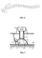
- a third embodimentis an optical 2D location sensor technology similar or identical to those used in an optical computer mouse, as in Figures 3 and 7 .
- the sensorprimarily consists of a light source 13, a translucent membrane or cavity 16, a lens 14 to collimate the reflected light from the skin 18, which also goes through the acoustic coupling gel 19 and continues through an optical guide to an optical sensor array 20 embedded in an integrated circuit 17.
- the optical sensoris attached to or built into a transducer, generally like that of Figure 5 .
- the sensor informationis passed through the transducer cable and processed in the system to find the position and velocity of the transducer. Any speckle, phase shift, frequency shift or other characteristics may be used to detect motion and velocity.
- the sensor informationmay be wirelessly communicated to the system.
- the optical 2D location sensorcan lose track of the transducer position if lifted from the surface (skin). This can be overcome with a simple calibration process, whereby the user moves the transducer to a marked calibration spot on the skin, push a calibration button on the transducer or on the system, and moves the transducer on the skin to the desired location.
- This third embodimentis very adaptable to a scanning plan in which the user graphically composes a 3D volume using software within the system or off line, showing the relative location and amount of treatment wanted, both with respect to cavitation (fat emulsification) , heating (skin tightening) , or other aesthetic/ dermatologic/ therapeutic treatments.
- Off line use of the scanning plan softwareallows data transfer to the system.
- the systemcan keep track of the transducer's location and in real time can adjust critical parameters such as MI, T I and focal depth (if equipped with electronic focusing) , so the desired treatment "dose” eventually will be delivered.
- critical parameterssuch as MI, T I and focal depth (if equipped with electronic focusing)
- the real time difference between the desired and actual delivered "dose”can also be displayed on the system graphically in a 2D format, so the user can concentrate the transducer motion in the area where more treatment is needed. This allows the user to move the transducer freely within certain boundaries with respect to both position and speed.
- the transducerneeds to be oriented perpendicular to the skin and in the case of a brush-beam transducer, the scanning velocity vector needs to be perpendicular to the brush width direction.
- an angular error relative to the exact perpendicularityis a cosine function, meaning that it is a weak dependency, so that in reality, perpendicularity need not be monitored, but can be continuously estimated by the user.
- the suggested speed shown by the various embodiments of the speed indicatorcan be based on MI, T I and instantaneous transducer face temperatures and/or acquired data from animal and clinical studies. While the above methods are intended to be used in conjunction with a non-invasive ultrasound lipoplasty transducer, the inventions, the scanning light source of the first two embodiments can be used on handheld transducers for other modalities, including aesthetic, dermatologic, or other therapeutic applications.
- a reference to a handheld external ultrasound treatment transduceris a reference to a handheld external ultrasound transducer useable for lipoplasty, skin tightening, aesthetic, dermatologic/, and other therapeutic purposes.
Landscapes
- Health & Medical Sciences (AREA)
- Engineering & Computer Science (AREA)
- Biomedical Technology (AREA)
- Nuclear Medicine, Radiotherapy & Molecular Imaging (AREA)
- Radiology & Medical Imaging (AREA)
- Life Sciences & Earth Sciences (AREA)
- Animal Behavior & Ethology (AREA)
- General Health & Medical Sciences (AREA)
- Public Health (AREA)
- Veterinary Medicine (AREA)
- Ultra Sonic Daignosis Equipment (AREA)
- Surgical Instruments (AREA)
Description
- The present invention relates to the field of non-invasive external ultrasound lipoplasty, skin tightening, and various non-invasive aesthetic, dermatologic, and therapeutic applications.
- During a non-invasive external ultrasound lipoplasty, skin tightening, aesthetic, dermatologic, or other therapeutic procedure with a handheld transducer, it becomes particularly important to apply and distribute the ultrasound energy dose according to the amount and location of the fat to be emulsified, the degree and location of skin tightening needed, or the extent and type of aesthetic, dermatologic, or other therapeutic desired effect.
- For this purpose the transducer's movement or instantaneous scanning speed needs to be known or better yet its position from which the scanning speed can be easily derived.
U.S. Patent No. 7,347,855 teaches a passive system of computerized tracking of a multiplicity of target volumes with compensation for body movements.U.S. Patent No. 6,645,162 teaches an active tracking system depicted in their Figures 12 and 13 guiding a transducer in a linear motion.- "Selective Creation of Thermal Injury Zones in the Superficial Musculoaponeurotic System Using Intense Ultrasound Therapy", (Matthew W. White et al., ARCH FACIAL PLAST SURG, Vol. 9, Jan/Feb 2007) shows an ultrasound probe by Ulthera with an internal transducer performing a controlled linear motion, thereby acting as an active tracking system.
U.S. Patent No. 7,150,716 is specific to diagnostic ultrasound, and teaches two methods (and systems) of detecting transducer scanning speed, namely one through the use of an sensor similar to an optical computer mouse and another through real time de-correlation of ultrasound images.U.S. Patent No. 5,645,066 discloses an apparatus according to the preamble of claim 1.- In the case of a handheld transducer without hardware to do the spatial and time feedback, the control has to come through the operator. It should be realized that the optimum speed of the transducer across the skin is strongly related to the optimum local exposure time. Too short an exposure time (fast motion) will not give adequate cavitation or heat (when needed) and could therefore reduce the efficacy of the procedure to near zero. Too slow a motion could create too much cavitation or heat with the potential for indiscriminant tissue destruction. In order to separate cavitation and heating further, there may be cases where multiple passes over the same area are necessary.
Figure 1a is a functional block diagram of one embodiment not forming part of the present invention.Figure 1b is a functional block diagram of an alternate form of the embodiment offigure 1a .Figure 2a is a functional block diagram of an embodiment of the present invention.Figure 2b is a functional block diagram of alternate form of the second embodiment.Figure 3 is a functional block diagram of still another embodiment not forming part of the present invention.Figure 4 is a view of a graphical user interface (e.g., touch screen display menu) with a scanning speed indicator in accordance with the embodiment ofFigure 1a .Figure 5 is a transducer with an integral scanning speed indicator, which in this example consists of five LEDs, in accordance with the embodiment ofFigure 1b .Figure 6 is a flexible scanning speed guidance strip with built in LEDs in accordance with the embodiments ofFigures 2a and2b .Figure 7 is a cross sectional view of an exemplary optical sensor in accordance with still another embodiment not forming part of the present invention.- The optimum transducer "scanning" speed for delivering a predetermined dose of ultrasound to a desired treatment area determined by a scanning plan is a function of both the cavitation related Mechanical Index (MI) and tissue temperature Thermal Index (TI) settings. While cavitation is a threshold mechanism there is both an amplitude factor beyond the threshold level and an exposure time factor involved in emulsifying a certain fraction of the treated fat, whereby low settings require a slow scanning speed and high settings require faster scanning speeds. The relationships can be estimated from the numerical values of MI and TI and further refined empirically using data from animal and clinical studies. Furthermore, since the transducer is not 100% energy efficient, its face (skin contact area) will create heat and if not properly controlled may present a hazard for potential skin burns. Moving the transducer across the skin surface will also significantly reduce localized peak skin temperature. In the case where there is a sensor monitoring the transducer face temperature, control of the skin heating can be included in the speed indicator. If there is no transducer face temperature sensor the suggested transducer movement speed component due to tissue heating can be based on empirical data from animal and clinical studies.
- There are at least three approaches for addressing control of the ultrasound dose delivery, as summarized in
Figs. 1a and 1b, Figs. 2a and2b, and Fig. 3 - One method requires the user to be part of the feedback loop, whereby the system, the transducer, or a separate device acts as a visual guide for the user to apply the desired scanning speed. The first embodiment is an example of this approach.
- Another method consists of a subsystem that detects the transducer scanning velocity and in real time transfers this information to the system, which in turn adjusts parameters such as MI and TI (i.e., ultrasound dose) to achieve the desired effect based on the actual speed of transducer movement. This relieves the user from precisely matching the desired scanning speed, but still requires the user to keep track of the transducer position and the ultrasound beam focal depth. The second embodiment is an example of this.
- A third method monitors the transducer position, which is transferred to the system in real time. With this information and the presence of a clock, the transducer velocity may also be easily calculated. Now the system can automatically adjust the needed parameters such as MI, TI and focal length to accomplish the planned treatment, giving the user the freedom to move the transducer almost "at will". The third embodiment is an example of this.
- It should be noted that there is much more value in using a 3D coordinate system, where the (contoured) skin defines two of the dimensions and the depth below the skin surface is the third, rather than a Cartesian coordinate system fixed to the operating room or even fixed to localized patient movements.
- The connecting lines in the functional block diagrams in
Figures 1a to 3 have the following meaning. The occasional user control of the system/console is shown as 7.Item 8 indicates that the user reads the scanning speed indicator. Item 9 indicates that the user views the actual scanning speed of the transducer.Item 10 indicates that the user actually holds and moves the transducer.Item 11 shows the transmit signals from the system to the transducer.Item 12 shows the low level power supply and control signals from the system to the Scanning Speed Pad 5 or optical sensor.Item 13 indicates the path of sensor signals from the optical sensor to the built in Decoder, which translates the information into position and speed. - One embodiment (
Figures 1a and4 ) is to have a visual transducer scanning speed indicator on the transmitter (main unit, console or system) that moves with the same speed that is optimal for the transducer motion on the skin. The speed indicator can take the form of a movingcursor 2 on a screen 1 of the transmitter. The moving cursor can take many forms, the one shown inFigures 1a, 1b, 2a ,2b and4 through 6 consists of four moving dots (light sources such as LEDs). These may be sequentially switched on and off at a controlled rate, or the first switched on, the second switched on, etc. with all being switched off and the cycle repeated after the last light source has been switched on, either of which is to be considered sequential switching on, or scanning. The user can then practice matching that speed while holding the transducer near the screen. When sufficiently proficient he/she can match the speed when scanning on the skin. As verification, the user can mark the skin for a certain distance and calculate the time needed to traverse that distance based on the numerical value of the desired velocity. - Another version (
Figures 1b and5 ) of the first embodiment is to have a visual transducer scanning speed indicator on the transducer itself 3 , for example in the form of an array of visual indicators (light sources) such as Light Emitting Diodes (LEDs) 4 , which light up in a sequence corresponding to the desired speed of the transducer. It will then be up to the user to provide the "feedback loop" by moving the transducer at the indicated speed. Here the user can perform the same verification as described above. - A second embodiment is a separate flexible scanning speed guidance pad 5 (
Figures 2a ,2b and6 ), which can be placed on the patient adjacent to the intended transducer path. The flexible material can be silicone rubber or other material with LEDs (or other visual indicators) 6 molded in. The LEDs are sequentially switched on and off so that they provide visual scanning speed guidance in proximity to the transducer. The speed guidance pad can be manufactured in different lengths and/or from different materials to fit the desired treatment area, and can also be either disposable (single patient use), semi-disposable, or reusable. The LEDs can be powered either by batteries, as in the embodiment ofFigure 2a , or by the transmitter, embodiment ofFigure 2b , in which case a power cord is detachably connected to the guidance pad. By being connected to the transmitter, the system may display the scanning speed, scanning location or position, and range of scan distance if the pad is physically longer than the desired scan needed to match the system settings, while the battery operated solution either would require wireless transmission of the information, or require the user to set the scanning speed according to the transmitter's displayed parameters. - A third embodiment is an optical 2D location sensor technology similar or identical to those used in an optical computer mouse, as in
Figures 3 and7 . The sensor primarily consists of alight source 13, a translucent membrane orcavity 16, a lens 14 to collimate the reflected light from the skin 18, which also goes through theacoustic coupling gel 19 and continues through an optical guide to an optical sensor array 20 embedded in anintegrated circuit 17. As indicated inFigure 3 the optical sensor is attached to or built into a transducer, generally like that ofFigure 5 . The sensor information is passed through the transducer cable and processed in the system to find the position and velocity of the transducer. Any speckle, phase shift, frequency shift or other characteristics may be used to detect motion and velocity. - Alternatively the sensor information may be wirelessly communicated to the system.
- As with a computer mouse, the optical 2D location sensor can lose track of the transducer position if lifted from the surface (skin). This can be overcome with a simple calibration process, whereby the user moves the transducer to a marked calibration spot on the skin, push a calibration button on the transducer or on the system, and moves the transducer on the skin to the desired location.
- In the case of a "brush-beam" (non circular symmetric beam) it becomes important to scan approximately perpendicular to the width (long axis) direction of the brush-beam.
- This third embodiment is very adaptable to a scanning plan in which the user graphically composes a 3D volume using software within the system or off line, showing the relative location and amount of treatment wanted, both with respect to cavitation (fat emulsification) , heating (skin tightening) , or other aesthetic/ dermatologic/ therapeutic treatments.
- Off line use of the scanning plan software allows data transfer to the system. During the procedure, the system can keep track of the transducer's location and in real time can adjust critical parameters such as MI, T I and focal depth (if equipped with electronic focusing) , so the desired treatment "dose" eventually will be delivered. The real time difference between the desired and actual delivered "dose" can also be displayed on the system graphically in a 2D format, so the user can concentrate the transducer motion in the area where more treatment is needed. This allows the user to move the transducer freely within certain boundaries with respect to both position and speed.
- For the best outcome with respect to the treatment plan, the transducer needs to be oriented perpendicular to the skin and in the case of a brush-beam transducer, the scanning velocity vector needs to be perpendicular to the brush width direction. However, an angular error relative to the exact perpendicularity is a cosine function, meaning that it is a weak dependency, so that in reality, perpendicularity need not be monitored, but can be continuously estimated by the user.
- The suggested speed shown by the various embodiments of the speed indicator can be based on MI, T I and instantaneous transducer face temperatures and/or acquired data from animal and clinical studies. While the above methods are intended to be used in conjunction with a non-invasive ultrasound lipoplasty transducer, the inventions, the scanning light source of the first two embodiments can be used on handheld transducers for other modalities, including aesthetic, dermatologic, or other therapeutic applications. In the claims to follow, a reference to a handheld external ultrasound treatment transducer is a reference to a handheld external ultrasound transducer useable for lipoplasty, skin tightening, aesthetic, dermatologic/, and other therapeutic purposes.
- Thus, while certain preferred embodiments of the present invention have been disclosed and described herein for purposes of illustration and not for purposes of limitation, it will be understood by those skilled in the art that various changes in form and detail may be made therein without departing from the scope of the invention.
Claims (5)
- Apparatus for guiding the scanning speed a user moves a handheld device across a patient body comprising:a plurality of light sources (6)the light sources (6) being disposed to be viewable by the user for visual reference of the speed at which the light appears to progress along the rowcharacterized in thatthe plurality of light sources (6) are spaced apart in a row;a light source driver for sequentially illuminating the light sources (6);wherein the row of light sources are disposed on a flexible pad (5) for placing on the patient body adjacent to an area of the patient's body intended to be scanned or treated by the handheld device.
- The apparatus of claim 1 further comprising a user controlled input apparatus for varying the speed at which the light appears to progress along the row.
- The apparatus of claim 1 wherein the handheld device is a handheld external ultrasound treatment transducer and wherein the light sources are disposed to be viewable by the user of the external ultrasound treatment transducer for visual reference of the speed at which the light appears to progress along the row.
- The apparatus of claim 3 further comprising a user controlled input apparatus for varying the speed at which the light appears to progress along the row.
- The apparatus of claim 3 wherein the hand held device is a handheld external ultrasound lipoplasty transducer
Applications Claiming Priority (2)
| Application Number | Priority Date | Filing Date | Title |
|---|---|---|---|
| US99589507P | 2007-09-28 | 2007-09-28 | |
| PCT/US2008/078188WO2009043046A1 (en) | 2007-09-28 | 2008-09-29 | Handheld transducer scanning speed guides and position detectors |
Publications (3)
| Publication Number | Publication Date |
|---|---|
| EP2254477A1 EP2254477A1 (en) | 2010-12-01 |
| EP2254477A4 EP2254477A4 (en) | 2011-08-10 |
| EP2254477B1true EP2254477B1 (en) | 2013-05-29 |
Family
ID=40511916
Family Applications (1)
| Application Number | Title | Priority Date | Filing Date |
|---|---|---|---|
| EP08833737.3ANot-in-forceEP2254477B1 (en) | 2007-09-28 | 2008-09-29 | Handheld transducer scanning speed guides and position detectors |
Country Status (3)
| Country | Link |
|---|---|
| US (1) | US20100256489A1 (en) |
| EP (1) | EP2254477B1 (en) |
| WO (1) | WO2009043046A1 (en) |
Families Citing this family (34)
| Publication number | Priority date | Publication date | Assignee | Title |
|---|---|---|---|---|
| US10864385B2 (en) | 2004-09-24 | 2020-12-15 | Guided Therapy Systems, Llc | Rejuvenating skin by heating tissue for cosmetic treatment of the face and body |
| US8444562B2 (en) | 2004-10-06 | 2013-05-21 | Guided Therapy Systems, Llc | System and method for treating muscle, tendon, ligament and cartilage tissue |
| US8535228B2 (en) | 2004-10-06 | 2013-09-17 | Guided Therapy Systems, Llc | Method and system for noninvasive face lifts and deep tissue tightening |
| JP2008522642A (en) | 2004-10-06 | 2008-07-03 | ガイデッド セラピー システムズ, エル.エル.シー. | Method and system for beauty enhancement |
| US9827449B2 (en) | 2004-10-06 | 2017-11-28 | Guided Therapy Systems, L.L.C. | Systems for treating skin laxity |
| US8133180B2 (en) | 2004-10-06 | 2012-03-13 | Guided Therapy Systems, L.L.C. | Method and system for treating cellulite |
| US20060111744A1 (en) | 2004-10-13 | 2006-05-25 | Guided Therapy Systems, L.L.C. | Method and system for treatment of sweat glands |
| US8690779B2 (en) | 2004-10-06 | 2014-04-08 | Guided Therapy Systems, Llc | Noninvasive aesthetic treatment for tightening tissue |
| US11235179B2 (en) | 2004-10-06 | 2022-02-01 | Guided Therapy Systems, Llc | Energy based skin gland treatment |
| JP5094402B2 (en) | 2004-10-06 | 2012-12-12 | ガイデッド セラピー システムズ, エル.エル.シー. | Method and system for ultrasonic tissue processing |
| US9694212B2 (en) | 2004-10-06 | 2017-07-04 | Guided Therapy Systems, Llc | Method and system for ultrasound treatment of skin |
| US11883688B2 (en) | 2004-10-06 | 2024-01-30 | Guided Therapy Systems, Llc | Energy based fat reduction |
| US11207548B2 (en) | 2004-10-07 | 2021-12-28 | Guided Therapy Systems, L.L.C. | Ultrasound probe for treating skin laxity |
| US11724133B2 (en) | 2004-10-07 | 2023-08-15 | Guided Therapy Systems, Llc | Ultrasound probe for treatment of skin |
| US12102473B2 (en) | 2008-06-06 | 2024-10-01 | Ulthera, Inc. | Systems for ultrasound treatment |
| KR20110091832A (en) | 2008-06-06 | 2011-08-12 | 얼테라, 인크 | Tissue Imaging and Treatment Systems |
| CA2748362A1 (en) | 2008-12-24 | 2010-07-01 | Michael H. Slayton | Methods and systems for fat reduction and/or cellulite treatment |
| US20130018268A1 (en)* | 2011-07-12 | 2013-01-17 | Nivasonix, Llc | Scanning Speed Detection for Freehand High Frequency Ultrasound Transducers |
| CN103027717B (en)* | 2011-10-09 | 2015-09-16 | 北京汇福康医疗技术有限公司 | The position monitoring method of ultrasonic transducer and device |
| US8760308B2 (en)* | 2011-10-25 | 2014-06-24 | Lockheed Martin Corporation | Surface treatment pace meter |
| US20130289411A1 (en)* | 2012-04-26 | 2013-10-31 | dBMEDx INC | Apparatus to removably secure an ultrasound probe to tissue |
| US9510802B2 (en) | 2012-09-21 | 2016-12-06 | Guided Therapy Systems, Llc | Reflective ultrasound technology for dermatological treatments |
| CN104027893B (en) | 2013-03-08 | 2021-08-31 | 奥赛拉公司 | Apparatus and method for multifocal ultrasound therapy |
| CA2906787C (en)* | 2013-03-15 | 2020-02-18 | Sonovia Holdings Llc | Light and ultrasonic transducer device |
| EP3021941A1 (en)* | 2013-07-19 | 2016-05-25 | Koninklijke Philips N.V. | High-intensity focused ultrasound (hifu) probes with automated control |
| CA2925586A1 (en)* | 2013-10-11 | 2015-04-16 | Seno Medical Instruments, Inc. | Systems and methods for component separation in medical imaging |
| WO2015160708A1 (en) | 2014-04-18 | 2015-10-22 | Ulthera, Inc. | Band transducer ultrasound therapy |
| ES2939604T3 (en) | 2016-01-18 | 2023-04-25 | Ulthera Inc | Compact ultrasonic device having an annular ultrasonic array peripherally electrically connected to a flexible printed circuit board |
| WO2017205578A1 (en) | 2016-05-26 | 2017-11-30 | San Diego State University Research Foundation | Photoeradication of microorganisms with pulsed purple or blue light |
| PL3981466T3 (en) | 2016-08-16 | 2023-11-20 | Ulthera, Inc. | Systems and methods for cosmetic ultrasound treatment of skin |
| TWI797235B (en) | 2018-01-26 | 2023-04-01 | 美商奧賽拉公司 | Systems and methods for simultaneous multi-focus ultrasound therapy in multiple dimensions |
| US11944849B2 (en) | 2018-02-20 | 2024-04-02 | Ulthera, Inc. | Systems and methods for combined cosmetic treatment of cellulite with ultrasound |
| US11020605B2 (en) | 2018-05-29 | 2021-06-01 | Carewear Corp. | Method and system for irradiating tissue with pulsed blue and red light to reduce muscle fatigue, enhance wound healing and tissue repair, and reduce pain |
| US12377293B2 (en) | 2019-07-15 | 2025-08-05 | Ulthera, Inc. | Systems and methods for measuring elasticity with imaging of ultrasound multi-focus shearwaves in multiple dimensions |
Family Cites Families (15)
| Publication number | Priority date | Publication date | Assignee | Title |
|---|---|---|---|---|
| US3964297A (en)* | 1974-12-16 | 1976-06-22 | Ithaco, Incorporated | Ultrasonic inspection apparatus |
| US5800478A (en)* | 1996-03-07 | 1998-09-01 | Light Sciences Limited Partnership | Flexible microcircuits for internal light therapy |
| US5645066A (en)* | 1996-04-26 | 1997-07-08 | Advanced Technology Laboratories, Inc. | Medical ultrasonic diagnostic imaging system with scanning guide for three dimensional imaging |
| US6213781B1 (en)* | 1996-05-23 | 2001-04-10 | Technical Education Research Centers, Inc. | Educational game using selective light displacement to teach physical concepts |
| ATE313353T1 (en)* | 1997-08-25 | 2006-01-15 | Advanced Photodynamic Technolo | DEVICE FOR TOPICAL PHOTODYNAMIC THERAPY |
| US5954674A (en)* | 1997-10-13 | 1999-09-21 | Kinex Iha Corporation | Apparatus for gathering biomechanical parameters |
| US6259108B1 (en)* | 1998-10-09 | 2001-07-10 | Kinetic Sciences Inc. | Fingerprint image optical input apparatus |
| US6132379A (en)* | 1998-11-04 | 2000-10-17 | Patacsil; Estelito G. | Method and apparatus for ultrasound guided intravenous cannulation |
| WO2001070117A2 (en)* | 2000-03-23 | 2001-09-27 | Microheart, Inc. | Pressure sensor for therapeutic delivery device and method |
| US6645162B2 (en) | 2000-12-27 | 2003-11-11 | Insightec - Txsonics Ltd. | Systems and methods for ultrasound assisted lipolysis |
| US7347855B2 (en) | 2001-10-29 | 2008-03-25 | Ultrashape Ltd. | Non-invasive ultrasonic body contouring |
| AU2003219843B2 (en)* | 2002-02-20 | 2009-04-23 | Medicis Technologies Corporation | Ultrasonic treatment and imaging of adipose tissue |
| US7150716B2 (en) | 2003-02-20 | 2006-12-19 | Siemens Medical Solutions Usa, Inc. | Measuring transducer movement methods and systems for multi-dimensional ultrasound imaging |
| US20050038343A1 (en)* | 2003-07-10 | 2005-02-17 | Alfred E. Mann Institute For Biomedical Research At The University Of Southern California | Apparatus and method for locating a bifurcation in an artery |
| US8235909B2 (en)* | 2004-05-12 | 2012-08-07 | Guided Therapy Systems, L.L.C. | Method and system for controlled scanning, imaging and/or therapy |
- 2008
- 2008-09-29EPEP08833737.3Apatent/EP2254477B1/ennot_activeNot-in-force
- 2008-09-29USUS12/680,538patent/US20100256489A1/ennot_activeAbandoned
- 2008-09-29WOPCT/US2008/078188patent/WO2009043046A1/enactiveApplication Filing
Also Published As
| Publication number | Publication date |
|---|---|
| EP2254477A4 (en) | 2011-08-10 |
| WO2009043046A1 (en) | 2009-04-02 |
| EP2254477A1 (en) | 2010-12-01 |
| US20100256489A1 (en) | 2010-10-07 |
Similar Documents
| Publication | Publication Date | Title |
|---|---|---|
| EP2254477B1 (en) | Handheld transducer scanning speed guides and position detectors | |
| US11406461B2 (en) | Delivery system and method for delivering material to a target site during a medical procedure | |
| AU2004311419B2 (en) | Systems and methods for the destruction of adipose tissue | |
| EP3280495B1 (en) | System and method for increased control of ultrasound treatment | |
| US10905900B2 (en) | Systems and methods for ultrasound treatment | |
| KR102746886B1 (en) | Ultrasound treatment system | |
| EP2731675B1 (en) | Systems and methods for coupling an ultrasound source to tissue | |
| US20150374333A1 (en) | Systems for cosmetic treatment | |
| KR20250099056A (en) | Ultrasonic device and its method of guiding irradiation | |
| HK1250674A1 (en) | System and method for increased control of ultrasound treatment |
Legal Events
| Date | Code | Title | Description |
|---|---|---|---|
| PUAI | Public reference made under article 153(3) epc to a published international application that has entered the european phase | Free format text:ORIGINAL CODE: 0009012 | |
| 17P | Request for examination filed | Effective date:20100819 | |
| AK | Designated contracting states | Kind code of ref document:A1 Designated state(s):AT BE BG CH CY CZ DE DK EE ES FI FR GB GR HR HU IE IS IT LI LT LU LV MC MT NL NO PL PT RO SE SI SK TR | |
| AX | Request for extension of the european patent | Extension state:AL BA MK RS | |
| DAX | Request for extension of the european patent (deleted) | ||
| A4 | Supplementary search report drawn up and despatched | Effective date:20110708 | |
| RIC1 | Information provided on ipc code assigned before grant | Ipc:A61N 7/00 20060101ALN20110704BHEP Ipc:A61B 17/00 20060101ALN20110704BHEP Ipc:A61N 7/02 20060101AFI20110704BHEP | |
| REG | Reference to a national code | Ref country code:DE Ref legal event code:R079 Ref document number:602008025060 Country of ref document:DE Free format text:PREVIOUS MAIN CLASS: A61B0008000000 Ipc:A61N0007020000 | |
| GRAP | Despatch of communication of intention to grant a patent | Free format text:ORIGINAL CODE: EPIDOSNIGR1 | |
| RIC1 | Information provided on ipc code assigned before grant | Ipc:A61N 7/02 20060101AFI20121203BHEP Ipc:A61N 7/00 20060101ALN20121203BHEP Ipc:A61B 17/00 20060101ALN20121203BHEP | |
| GRAS | Grant fee paid | Free format text:ORIGINAL CODE: EPIDOSNIGR3 | |
| GRAA | (expected) grant | Free format text:ORIGINAL CODE: 0009210 | |
| AK | Designated contracting states | Kind code of ref document:B1 Designated state(s):AT BE BG CH CY CZ DE DK EE ES FI FR GB GR HR HU IE IS IT LI LT LU LV MC MT NL NO PL PT RO SE SI SK TR | |
| REG | Reference to a national code | Ref country code:GB Ref legal event code:FG4D | |
| REG | Reference to a national code | Ref country code:CH Ref legal event code:EP | |
| REG | Reference to a national code | Ref country code:AT Ref legal event code:REF Ref document number:613981 Country of ref document:AT Kind code of ref document:T Effective date:20130615 | |
| REG | Reference to a national code | Ref country code:IE Ref legal event code:FG4D | |
| REG | Reference to a national code | Ref country code:DE Ref legal event code:R096 Ref document number:602008025060 Country of ref document:DE Effective date:20130725 | |
| REG | Reference to a national code | Ref country code:AT Ref legal event code:MK05 Ref document number:613981 Country of ref document:AT Kind code of ref document:T Effective date:20130529 | |
| REG | Reference to a national code | Ref country code:LT Ref legal event code:MG4D | |
| PG25 | Lapsed in a contracting state [announced via postgrant information from national office to epo] | Ref country code:PT Free format text:LAPSE BECAUSE OF FAILURE TO SUBMIT A TRANSLATION OF THE DESCRIPTION OR TO PAY THE FEE WITHIN THE PRESCRIBED TIME-LIMIT Effective date:20130930 Ref country code:GR Free format text:LAPSE BECAUSE OF FAILURE TO SUBMIT A TRANSLATION OF THE DESCRIPTION OR TO PAY THE FEE WITHIN THE PRESCRIBED TIME-LIMIT Effective date:20130830 Ref country code:FI Free format text:LAPSE BECAUSE OF FAILURE TO SUBMIT A TRANSLATION OF THE DESCRIPTION OR TO PAY THE FEE WITHIN THE PRESCRIBED TIME-LIMIT Effective date:20130529 Ref country code:ES Free format text:LAPSE BECAUSE OF FAILURE TO SUBMIT A TRANSLATION OF THE DESCRIPTION OR TO PAY THE FEE WITHIN THE PRESCRIBED TIME-LIMIT Effective date:20130909 Ref country code:IS Free format text:LAPSE BECAUSE OF FAILURE TO SUBMIT A TRANSLATION OF THE DESCRIPTION OR TO PAY THE FEE WITHIN THE PRESCRIBED TIME-LIMIT Effective date:20130929 Ref country code:SE Free format text:LAPSE BECAUSE OF FAILURE TO SUBMIT A TRANSLATION OF THE DESCRIPTION OR TO PAY THE FEE WITHIN THE PRESCRIBED TIME-LIMIT Effective date:20130529 Ref country code:NO Free format text:LAPSE BECAUSE OF FAILURE TO SUBMIT A TRANSLATION OF THE DESCRIPTION OR TO PAY THE FEE WITHIN THE PRESCRIBED TIME-LIMIT Effective date:20130829 Ref country code:AT Free format text:LAPSE BECAUSE OF FAILURE TO SUBMIT A TRANSLATION OF THE DESCRIPTION OR TO PAY THE FEE WITHIN THE PRESCRIBED TIME-LIMIT Effective date:20130529 Ref country code:SI Free format text:LAPSE BECAUSE OF FAILURE TO SUBMIT A TRANSLATION OF THE DESCRIPTION OR TO PAY THE FEE WITHIN THE PRESCRIBED TIME-LIMIT Effective date:20130529 Ref country code:LT Free format text:LAPSE BECAUSE OF FAILURE TO SUBMIT A TRANSLATION OF THE DESCRIPTION OR TO PAY THE FEE WITHIN THE PRESCRIBED TIME-LIMIT Effective date:20130529 | |
| REG | Reference to a national code | Ref country code:NL Ref legal event code:VDEP Effective date:20130529 | |
| PG25 | Lapsed in a contracting state [announced via postgrant information from national office to epo] | Ref country code:HR Free format text:LAPSE BECAUSE OF FAILURE TO SUBMIT A TRANSLATION OF THE DESCRIPTION OR TO PAY THE FEE WITHIN THE PRESCRIBED TIME-LIMIT Effective date:20130529 Ref country code:BG Free format text:LAPSE BECAUSE OF FAILURE TO SUBMIT A TRANSLATION OF THE DESCRIPTION OR TO PAY THE FEE WITHIN THE PRESCRIBED TIME-LIMIT Effective date:20130829 Ref country code:PL Free format text:LAPSE BECAUSE OF FAILURE TO SUBMIT A TRANSLATION OF THE DESCRIPTION OR TO PAY THE FEE WITHIN THE PRESCRIBED TIME-LIMIT Effective date:20130529 | |
| PG25 | Lapsed in a contracting state [announced via postgrant information from national office to epo] | Ref country code:LV Free format text:LAPSE BECAUSE OF FAILURE TO SUBMIT A TRANSLATION OF THE DESCRIPTION OR TO PAY THE FEE WITHIN THE PRESCRIBED TIME-LIMIT Effective date:20130529 | |
| PG25 | Lapsed in a contracting state [announced via postgrant information from national office to epo] | Ref country code:CZ Free format text:LAPSE BECAUSE OF FAILURE TO SUBMIT A TRANSLATION OF THE DESCRIPTION OR TO PAY THE FEE WITHIN THE PRESCRIBED TIME-LIMIT Effective date:20130529 Ref country code:EE Free format text:LAPSE BECAUSE OF FAILURE TO SUBMIT A TRANSLATION OF THE DESCRIPTION OR TO PAY THE FEE WITHIN THE PRESCRIBED TIME-LIMIT Effective date:20130529 Ref country code:BE Free format text:LAPSE BECAUSE OF FAILURE TO SUBMIT A TRANSLATION OF THE DESCRIPTION OR TO PAY THE FEE WITHIN THE PRESCRIBED TIME-LIMIT Effective date:20130529 Ref country code:DK Free format text:LAPSE BECAUSE OF FAILURE TO SUBMIT A TRANSLATION OF THE DESCRIPTION OR TO PAY THE FEE WITHIN THE PRESCRIBED TIME-LIMIT Effective date:20130529 Ref country code:SK Free format text:LAPSE BECAUSE OF FAILURE TO SUBMIT A TRANSLATION OF THE DESCRIPTION OR TO PAY THE FEE WITHIN THE PRESCRIBED TIME-LIMIT Effective date:20130529 | |
| PG25 | Lapsed in a contracting state [announced via postgrant information from national office to epo] | Ref country code:IT Free format text:LAPSE BECAUSE OF FAILURE TO SUBMIT A TRANSLATION OF THE DESCRIPTION OR TO PAY THE FEE WITHIN THE PRESCRIBED TIME-LIMIT Effective date:20130529 Ref country code:NL Free format text:LAPSE BECAUSE OF FAILURE TO SUBMIT A TRANSLATION OF THE DESCRIPTION OR TO PAY THE FEE WITHIN THE PRESCRIBED TIME-LIMIT Effective date:20130529 Ref country code:RO Free format text:LAPSE BECAUSE OF FAILURE TO SUBMIT A TRANSLATION OF THE DESCRIPTION OR TO PAY THE FEE WITHIN THE PRESCRIBED TIME-LIMIT Effective date:20130529 | |
| PLBE | No opposition filed within time limit | Free format text:ORIGINAL CODE: 0009261 | |
| STAA | Information on the status of an ep patent application or granted ep patent | Free format text:STATUS: NO OPPOSITION FILED WITHIN TIME LIMIT | |
| PG25 | Lapsed in a contracting state [announced via postgrant information from national office to epo] | Ref country code:MC Free format text:LAPSE BECAUSE OF FAILURE TO SUBMIT A TRANSLATION OF THE DESCRIPTION OR TO PAY THE FEE WITHIN THE PRESCRIBED TIME-LIMIT Effective date:20130529 | |
| REG | Reference to a national code | Ref country code:CH Ref legal event code:PL | |
| 26N | No opposition filed | Effective date:20140303 | |
| REG | Reference to a national code | Ref country code:DE Ref legal event code:R097 Ref document number:602008025060 Country of ref document:DE Effective date:20140303 | |
| REG | Reference to a national code | Ref country code:DE Ref legal event code:R119 Ref document number:602008025060 Country of ref document:DE Effective date:20140401 | |
| REG | Reference to a national code | Ref country code:FR Ref legal event code:ST Effective date:20140530 | |
| REG | Reference to a national code | Ref country code:IE Ref legal event code:MM4A | |
| PG25 | Lapsed in a contracting state [announced via postgrant information from national office to epo] | Ref country code:LI Free format text:LAPSE BECAUSE OF NON-PAYMENT OF DUE FEES Effective date:20130930 Ref country code:CH Free format text:LAPSE BECAUSE OF NON-PAYMENT OF DUE FEES Effective date:20130930 Ref country code:IE Free format text:LAPSE BECAUSE OF NON-PAYMENT OF DUE FEES Effective date:20130929 | |
| PG25 | Lapsed in a contracting state [announced via postgrant information from national office to epo] | Ref country code:FR Free format text:LAPSE BECAUSE OF NON-PAYMENT OF DUE FEES Effective date:20130930 Ref country code:DE Free format text:LAPSE BECAUSE OF NON-PAYMENT OF DUE FEES Effective date:20140401 | |
| PGFP | Annual fee paid to national office [announced via postgrant information from national office to epo] | Ref country code:GB Payment date:20141021 Year of fee payment:7 | |
| PG25 | Lapsed in a contracting state [announced via postgrant information from national office to epo] | Ref country code:CY Free format text:LAPSE BECAUSE OF FAILURE TO SUBMIT A TRANSLATION OF THE DESCRIPTION OR TO PAY THE FEE WITHIN THE PRESCRIBED TIME-LIMIT Effective date:20130529 Ref country code:TR Free format text:LAPSE BECAUSE OF FAILURE TO SUBMIT A TRANSLATION OF THE DESCRIPTION OR TO PAY THE FEE WITHIN THE PRESCRIBED TIME-LIMIT Effective date:20130529 Ref country code:MT Free format text:LAPSE BECAUSE OF FAILURE TO SUBMIT A TRANSLATION OF THE DESCRIPTION OR TO PAY THE FEE WITHIN THE PRESCRIBED TIME-LIMIT Effective date:20130529 | |
| PG25 | Lapsed in a contracting state [announced via postgrant information from national office to epo] | Ref country code:LU Free format text:LAPSE BECAUSE OF NON-PAYMENT OF DUE FEES Effective date:20130929 Ref country code:HU Free format text:LAPSE BECAUSE OF FAILURE TO SUBMIT A TRANSLATION OF THE DESCRIPTION OR TO PAY THE FEE WITHIN THE PRESCRIBED TIME-LIMIT; INVALID AB INITIO Effective date:20080929 | |
| GBPC | Gb: european patent ceased through non-payment of renewal fee | Effective date:20150929 | |
| PG25 | Lapsed in a contracting state [announced via postgrant information from national office to epo] | Ref country code:GB Free format text:LAPSE BECAUSE OF NON-PAYMENT OF DUE FEES Effective date:20150929 |