EP2253274A1 - Device for ultrasound-supported computer tomography with expanded measurement range - Google Patents
Device for ultrasound-supported computer tomography with expanded measurement rangeDownload PDFInfo
- Publication number
- EP2253274A1 EP2253274A1EP10004023AEP10004023AEP2253274A1EP 2253274 A1EP2253274 A1EP 2253274A1EP 10004023 AEP10004023 AEP 10004023AEP 10004023 AEP10004023 AEP 10004023AEP 2253274 A1EP2253274 A1EP 2253274A1
- Authority
- EP
- European Patent Office
- Prior art keywords
- container
- buffer element
- coupling medium
- ultrasound
- adapter support
- Prior art date
- Legal status (The legal status is an assumption and is not a legal conclusion. Google has not performed a legal analysis and makes no representation as to the accuracy of the status listed.)
- Withdrawn
Links
- 238000002591computed tomographyMethods0.000titleclaimsdescription6
- 238000005259measurementMethods0.000title1
- 230000008878couplingEffects0.000claimsabstractdescription37
- 238000010168coupling processMethods0.000claimsabstractdescription37
- 238000005859coupling reactionMethods0.000claimsabstractdescription37
- 239000012530fluidSubstances0.000claimsabstractdescription10
- 238000007789sealingMethods0.000claimsabstractdescription10
- 238000002604ultrasonographyMethods0.000claimsdescription23
- 238000011144upstream manufacturingMethods0.000claimsdescription2
- 239000000969carrierSubstances0.000claims1
- 210000000481breastAnatomy0.000description14
- 238000009607mammographyMethods0.000description8
- 238000011156evaluationMethods0.000description5
- 210000000038chestAnatomy0.000description4
- 238000000034methodMethods0.000description4
- 238000001514detection methodMethods0.000description3
- 238000003384imaging methodMethods0.000description3
- 238000012545processingMethods0.000description3
- 206010028980NeoplasmDiseases0.000description2
- 230000005540biological transmissionEffects0.000description2
- 230000000284resting effectEffects0.000description2
- 230000001954sterilising effectEffects0.000description2
- 238000004659sterilization and disinfectionMethods0.000description2
- 238000012800visualizationMethods0.000description2
- 238000010521absorption reactionMethods0.000description1
- 238000013459approachMethods0.000description1
- 239000007864aqueous solutionSubstances0.000description1
- 210000000746body regionAnatomy0.000description1
- 238000002405diagnostic procedureMethods0.000description1
- 238000005516engineering processMethods0.000description1
- 239000007788liquidSubstances0.000description1
- 230000000630rising effectEffects0.000description1
- 238000000926separation methodMethods0.000description1
- 239000007787solidSubstances0.000description1
- 239000000243solutionSubstances0.000description1
- XLYOFNOQVPJJNP-UHFFFAOYSA-NwaterSubstancesOXLYOFNOQVPJJNP-UHFFFAOYSA-N0.000description1
- 238000009736wettingMethods0.000description1
Images

Classifications
- A—HUMAN NECESSITIES
- A61—MEDICAL OR VETERINARY SCIENCE; HYGIENE
- A61B—DIAGNOSIS; SURGERY; IDENTIFICATION
- A61B8/00—Diagnosis using ultrasonic, sonic or infrasonic waves
- A61B8/40—Positioning of patients, e.g. means for holding or immobilising parts of the patient's body
- A61B8/406—Positioning of patients, e.g. means for holding or immobilising parts of the patient's body using means for diagnosing suspended breasts
- A—HUMAN NECESSITIES
- A61—MEDICAL OR VETERINARY SCIENCE; HYGIENE
- A61B—DIAGNOSIS; SURGERY; IDENTIFICATION
- A61B8/00—Diagnosis using ultrasonic, sonic or infrasonic waves
- A61B8/08—Clinical applications
- A61B8/0825—Clinical applications for diagnosis of the breast, e.g. mammography
- A—HUMAN NECESSITIES
- A61—MEDICAL OR VETERINARY SCIENCE; HYGIENE
- A61B—DIAGNOSIS; SURGERY; IDENTIFICATION
- A61B8/00—Diagnosis using ultrasonic, sonic or infrasonic waves
- A61B8/42—Details of probe positioning or probe attachment to the patient
- A61B8/4272—Details of probe positioning or probe attachment to the patient involving the acoustic interface between the transducer and the tissue
- A61B8/4281—Details of probe positioning or probe attachment to the patient involving the acoustic interface between the transducer and the tissue characterised by sound-transmitting media or devices for coupling the transducer to the tissue
Definitions
- the inventionrelates to a device for an ultrasound-assisted computed tomography, preferably for breast examinations (sonographic mammography) according to the first patent claim.
- Ultrasound examinationsare regarded as imaging diagnostic methods in medical technology not only as particularly economical, but also tissue-preserving.
- a medical ultrasound deviceconsists essentially of a transducer with a number of ultrasonic transducers and a control and evaluation unit which emits the control pulses for the ultrasonic transducer and the ultrasound signals reflected in the patient body (echo signals) resumes and amplified as electrical signals to the evaluation forwards (impulse -echo method).
- the displayis usually done in real time on a screen.
- US 4,478,083discloses a system for ultrasound mammography in which a female breast is inserted and positioned from above into a cylindrical container.
- the containerhas a plurality of fixed ultrasonic transducers over the entire cylindrical wall surface.
- DE 28 27 423 A1Describe a device for determining the internal structure of a body by means of sound beams, in which the body is introduced into a container filled with a coupling medium container and is sonicated in this with the ultrasonic transmission method.
- one or more ultrasound transmitterssend a sound beam through the body to at least one ultrasound transducer as receiver, the received signals in an evaluation unit electronically processed, stored and then determined the distribution of the sound refractive index and the absorption coefficient.
- the DE 100 50 232 A1discloses a high-resolution ultrasound tomograph for tissue examinations of body parts and in particular of the female breast according to the transmission scattering and pulse-echo method. It consists of an open-topped and filled with a coupling medium container into which the body part to be examined is introduced, with fixed to the container wall over the entire wall surface fixed ultrasonic transducers whose main emission is aligned in each case perpendicularly from the wall surface into the container interior. A computer-aided control and evaluation unit is used for the individual control of ultrasonic transducers and the visualization of the signals received from selected receivers.
- the object of the inventionis to propose a device for an ultrasound-assisted computed tomography with an extended measuring range, which in particular enables reliable mammography of the entire breast, ie also in the vicinity of the thorax, ie in the region of the container opening.
- an apparatus for an ultrasound-supported computed tomography on objectscomprising a container filled with a coupling medium container with a container opening.
- the containerhas a number of ultrasonic transducers which act on the coupling medium in the container.
- the ultrasonic transducersare mounted on the wall of the container or in a separate carrier, which can be handled remotely in the container, such as e.g. an inner container fixed.
- a feature of the solutionincludes an adapter pad for an object, preferably the patient's body surface around a limb to be examined, such as the thorax area around a patient's breast to be examined on the container opening.
- the adapter padalso serves as a sealing element between the container opening and the object and thus prevents leakage of ultrasound coupling medium, preferably a gel (ultrasound coupling gel) or a liquid from the container.
- the adapter supporthas a resilient buffer element, which applies in an annular, positive and sealing manner to the object or the aforementioned patient body, preferably to the thorax of a patient.
- the buffer elementis preferably formed by an annular buffer element filled with a fluid or gel.
- the annular buffer elementpreferably has a shape that is adapted to the object or the patient's body, preferably prefabricated, and depending on which one is to be examined resting object or patient body in the adapter support is exchangeable designed.
- the annular buffer elementis therefore preferably not constantly thick and topograhisch and running in the same cross-section, but in their cross section adapted to the bridging gap between the patient's body or object and the inclusion of the buffer member in the adapter pad bridging. To avoid unwanted ultrasonic reflections on the buffer element, this has an acoustic impedance, which preferably deviates at most 5% from that of the coupling medium.
- the buffer elementpreferably consists of a plastic sleeve filled with the coupling medium, preferably an aqueous solution or water.
- the plastic shell itselfis preferably to be designed with little reflection on ultrasonic waves, preferably thin with a wall thickness preferably less than 1 mm, more preferably less than 0.5 mm wall thickness and rough surfaces.
- the adapter padbut at least the buffer element is optionally designed interchangeable. It not only favors fast sterilization (or sterilization) of the ultrasound device but also a possibility of adapting the device to different geometries of the patient's body or of the object in the contact area during sonographic examinations.
- the deviceadditionally has a discharge for the coupling medium in the region of the adapter support.
- the derivativeis preferably carried out as active suction.
- the discharge or suctionpreferably takes place in the region of the container opening, ie at the highest point of the volume available for the coupling medium in the container. This also ensures that the container is completely filled with an object or patient lying on the coupling medium and in particular upwardly rising air or gas components are derived or sucked.
- a possible embodimenthas a derivative or suction of the aforementioned type with a ring drain in the adapter pad.
- the annular drainagecomprises at least one drainage channel and serves to receive leakage currents of the coupling medium which occur between the object or patient and the buffer element or possible movable (rotatable or displaceable) connections between the adapter support and the container.
- the annular channelserves as collecting or collecting channel for the emerging from the container coupling medium.
- Another possible embodimentcomprises means for an active fluid circuit for the coupling medium.
- the coupling mediumis passed on to the discharge or suction in the region of the container opening or the adapter support, if necessary via a further annular channel or another collection or collecting channel, and from there into a drain or outlet.
- the outflow or outletpreferably opens directly into a circulating pump, preferably with an upstream gas separator and / or filter for the separation of gaseous or solid components. By the circulation pump, a return of the coupling medium is carried back into the container.
- the devicehas a traversing device of the container below the adapter support.
- a vertical traversing devicemakes it possible, for example, to approach the container with the ultrasound transducers from below against a patient lying on the adapter support or against an overlying patient or object. Lateral, ie horizontal adjustment or twisting possibilities for one or more translational or rotational degrees of freedom also allow any necessary adjustment of the ultrasonic transducer to the object to be examined.
- the adapter supportas a form-fitting, conformable to the patient's body sealing element and the container, a largely dense containment is created, which with coupling medium such.
- fluid filledvirtually encloses the entire breast, thus making an extended area of the breast accessible to US mammography.
- Essential in the inventionis a maximum access range of the mamma or another object through the ultrasound coupling medium and thus for the ultrasonic signals.
- the detection range of sonographic examinations with echo evaluation (impulse echo method) with the access area via the breastalso extends into the adjacent areas of the patient, i. beyond the edge of the container in a particularly advantageous manner, if above all a sufficient sonographic connection in the region near the adapter support and thus the largest possible sonographic access angle to the tissue to be examined is ensured.
- An aforementioned sealing adapter padnot only allows a maximum possible increase in the container cavity flooded with coupling medium up to the armpit area of a patient, but also the use of particularly low-viscosity coupling media.
- An ultrasound examinationis possible up to tissue located above the edge of the measuring container, wherein a filling of the buffer element of the adapter support with coupling medium causes a further enlargement of the measuring range.
- the illustrated embodimentdiscloses a device for ultrasound-assisted computed tomography, especially on the female breast, for extended range ultrasound mammography.
- the figuresshow the device without a detailed representation of the associated units for the control, data processing or visualization.
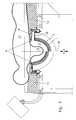
- Fig.1shows the device without an object to be examined with a container 1 of a plurality of this inside ultrasonic transducers 2, which are aligned in the Be bachelorerkavmaschine 3 and an upwardly open container edge 4.
- the containeris shell or hemisphere, ie, it has a rounded and ground occupied by ultrasonic transducers. He is thus particularly suitable for the aforementioned sonographic detection of body regions of the patient, which are arranged above the container rim 4 or the patch pad 5 placed on this, ie area that are not lapped by coupling medium.
- the adapter support 5comprises an annular buffer element 6, shown by way of example with a circular cross-section as a sealing positive fit of a patient and an annular support 7 with an annular channel 8 with sliding seal 9 to an annular sump 10 with drain 11 for the out of the container in the annular channel as collecting channel ausmündende coupling medium.
- the sliding sealacts against a container-side shielding plate 17, which also forms the lower boundary of the annular channel 8 . It allows vertical and rotational relative movements from container to adapter support.
- the drip pan 10serves to dissipate leakage losses of the coupling medium, which is pressed by said slide seal or between Pufferlement 6 and patient body 13 (see. Fig.2 ) in a drainage channel 16 and from there into the Drip tray 10 is passed. Drip pan 10, drain 11 and drain channel 16 thus form a ring drainage, wherein the coupling medium derived thereby is preferably cleaned off and / or stored in a collecting container intermediately stored in the container.
- the annular channel 8opens into an outlet 18, via which the coupling medium can be discharged or sucked off, preferably in the context of an aforementioned fluid circuit.
- the coupling medium collected via the annular drainageis preferably also fed back.
- An outletis used in the embodiment in the shielding plate 17 .
- This embodimentmakes do without flexible lines that is advantageous only with rigid fluid connections, when the forwarding, processing and re-introduction of the coupling medium are carried out in the container of fluidly connected to the container fluidic units such as pumps, filters or lines.
- An alternative arrangement of the outlet in the carrier 7favors a forwarding and processing without flexible pipe connections in stationary systems.
- Fig.2shows the in Fig.1 illustrated embodiment with resting on the patient support patient 13 with a hanging in the Be Strukturerkavmaschine 3 down mamma 14.
- the available cavity for the coupling medium in the containeris thus limited by the container walls or ultrasonic transducers 2 on the one hand and by the adapter support and the breast on the other.
- Fig.1 and 2further show an axis of symmetry 15 of the container.
- the half of the figure to the left of this line of symmetryeach show a container in the upper position, that is to say in the preferred position for sonographic examination.
- the right half of the imageshows a deviating, ie vertically lowered, positioning of the container with a corresponding widening of the annular gap 8.
- a manual, hydraulic or electromechanical traversing device for the vertical adjustmentis not indicated in the figures, but is preferably arranged underneath the container and grips it preferably in the region of symmetry axes 15 .
- Alternative traversing devicesare arranged on the adapter support and preferably engage at least three locations arranged on the circumference of the container opening on the container.
- the control of the ultrasonic transducer 2 and an adjusting deviceis not shown, but takes place for example via an interface laterally of the patient bed, which allows rapid replacement of the device, for example to a central high-performance computer unit and thus a rapid sequence of sonographic examinations of a variety of patients.
Landscapes
- Life Sciences & Earth Sciences (AREA)
- Health & Medical Sciences (AREA)
- Biomedical Technology (AREA)
- Biophysics (AREA)
- Nuclear Medicine, Radiotherapy & Molecular Imaging (AREA)
- Pathology (AREA)
- Radiology & Medical Imaging (AREA)
- Engineering & Computer Science (AREA)
- Physics & Mathematics (AREA)
- Heart & Thoracic Surgery (AREA)
- Medical Informatics (AREA)
- Molecular Biology (AREA)
- Surgery (AREA)
- Animal Behavior & Ethology (AREA)
- General Health & Medical Sciences (AREA)
- Public Health (AREA)
- Veterinary Medicine (AREA)
- Ultra Sonic Daignosis Equipment (AREA)
Abstract
Description
Translated fromGermanDie Erfindung betrifft eine Vorrichtung für eine Ultraschallgestützte Computertomographie vorzugsweise für Brustuntersuchungen (sonographische Mammographie) gemäß des ersten Patentanspruchs.The invention relates to a device for an ultrasound-assisted computed tomography, preferably for breast examinations (sonographic mammography) according to the first patent claim.
Ultraschalluntersuchungen gelten als bildgebende Diagnoseverfahren in der Medizintechnik nicht nur als besonders wirtschaftlich, sondern auch gewebeschonend.Ultrasound examinations are regarded as imaging diagnostic methods in medical technology not only as particularly economical, but also tissue-preserving.
Ein medizinisches Ultraschallgerät besteht im wesentlichen aus einem Schallkopf mit einer Anzahl von Ultraschallwandlern sowie einer Steuer- und Auswerteeinheit, welche die Steuerimpulse für die Ultraschallwandler aussendet sowie die im Patientenkörper reflektierenden Ultraschallsignale (Echosignale) wieder aufnimmt und als elektrische Signale verstärkt an die Auswerteeinheit weiterleitet (Impuls-Echo-Verfahren). Die Anzeige erfolgt in der Regel in Echtzeit an einem Bildschirm.A medical ultrasound device consists essentially of a transducer with a number of ultrasonic transducers and a control and evaluation unit which emits the control pulses for the ultrasonic transducer and the ultrasound signals reflected in the patient body (echo signals) resumes and amplified as electrical signals to the evaluation forwards (impulse -echo method). The display is usually done in real time on a screen.
Ferner wird in
Auch die
Alle genannten Systeme ermöglichen eine hochauflösende tomographischen Abbildung einer in den Behälter von oben eingebrachten Extremität eines Patientenkörpers wie z.B. eine Mamma oder eines anderen beliebigen mit Ultraschallwellen durchdringbaren Körpers. Allerdings ist Benetzung eines Gewebebereichs mit Ankopplungsmedium nahe der oben liegenden Behälteröffnung problematisch und nur bedingt reproduzierbar. Die Anbindung der Ultraschallwellen ist in diesen Bereichen folglich nicht optimal, wodurch auch die Abbildungsgenauigkeit an ihre Grenzen stößt.All of these systems enable high-resolution tomographic imaging of a limb of a patient's body, such as a limb, inserted into the container from above. a mamma or any other ultrasound wave penetrable body. However, wetting of a tissue area with coupling medium near the top of the container opening is problematic and only partially reproducible. The connection of the ultrasonic waves is therefore not optimal in these areas, whereby the imaging accuracy reaches its limits.
Bekanntlich entstehen Tumore in der Mamma zum überwiegenden Teil nicht in allzu weiter Entfernung zum Brustkorb, d.h. in einem Gewebebereich, der bei einer sonographischen Mammographie an einer der vorgenannten Ultraschallcomputertomographen nur wenig in den Behälter eintaucht und sich im Bereich der Behälteröffnung befindet. Eine Erfassung dieser Tumore mittels eines Ultraschallcomputertomographen der vorgenannten Art ist daher nur begrenzt und mit einer reduzierten Genauigkeit möglich. Davon ausgehend liegt die Aufgabe der Erfindung darin, eine Vorrichtung für eine Ultraschallgestützte Computertomographie mit einem erweiterten Messbereich vorzuschlagen, die insbesondere eine zuverlässige Mammographie der gesamten Mamma, d.h. auch in der Nähe des Brustkorbes, d.h. im Bereich der Behälteröffnung ermöglicht.As is known, tumors in the breast do not develop too far away from the thorax, ie in a tissue region which only slightly dips into the container during ultrasound mammography on one of the abovementioned ultrasound computer tomographs and is located in the region of the container opening. A detection of these tumors by means of an ultrasound computer tomograph of the aforementioned type is therefore limited and possible with reduced accuracy. Based on this, the object of the invention is to propose a device for an ultrasound-assisted computed tomography with an extended measuring range, which in particular enables reliable mammography of the entire breast, ie also in the vicinity of the thorax, ie in the region of the container opening.
Die Aufgabe wird mit einer Vorrichtung mit den Merkmalen des Anspruch 1 gelöst. Unteransprüche geben vorteilhafte Ausführungsformen wieder.The object is achieved with a device having the features of claim 1. Subclaims give advantageous embodiments again.
Zur Lösung der Aufgabe wird eine Vorrichtung für eine Ultraschallgestützte Computertomographie an Objekten vorgeschlagen, umfassend einen mit einem Ankopplungsmedium gefüllten Behälter mit einer Behälteröffnung. Der Behälter weist eine Anzahl von Ultraschallwandlern auf, die im Behälter auf das Ankopplungsmedium einwirken. Dabei sind die Ultraschallwandler je nach Ausführungsform an der Wandung des Behälters oder in einem separaten im Behälter fernhantierbar beweglichen Träger wie z.B. ein Innenbehälter fixiert.To achieve the object, an apparatus for an ultrasound-supported computed tomography on objects is proposed, comprising a container filled with a coupling medium container with a container opening. The container has a number of ultrasonic transducers which act on the coupling medium in the container. Depending on the embodiment, the ultrasonic transducers are mounted on the wall of the container or in a separate carrier, which can be handled remotely in the container, such as e.g. an inner container fixed.
Ein Merkmal der Lösung umfasst eine Adapterauflage für ein Objekt, vorzugsweise die Patientenkörperoberfläche um eine zu untersuchende Extremität wie z.B. der Brustkorbbereich um eine zu untersuchende Brust einer Patientin auf der Behälteröffnung. Die Adapterauflage dient gleichzeitig als Dichtungselement zwischen Behälteröffnung und Objekt und verhindert auf diese Weise ein Austreten von Ultraschall-Ankopplungsmedium, vorzugsweise einem Gel (Ultraschallankopplungsgel) oder einer Flüssigkeit aus dem Behälter. Die Adapterauflage weist ein nachgiebiges Pufferelement auf, das sich ringförmig, formschlüssig und dichtend an das Objekt oder den vorgenannten Patientenkörper, vorzugsweise an den Brustkorb einer Patientin anlegt. Das Pufferelement wird vorzugsweise durch ein ringförmiges und mit einem Fluid oder Gel gefülltes Pufferelement gebildet. Es weist bevorzugt eine an das Objekt oder dem Patientenkörper angepasste Form vorzugsweise konfektioniert auf, wobei es je nach zu untersuchenden aufliegenden Objekt oder Patientenkörper in der Adapterauflage austauschbar gestaltbar ist. Das ringförmige Pufferelement ist folglich vorzugsweise nicht konstant dick und topograhisch und im Querschnitt gleich bleibend ausgeführt, sondern in ihrem Querschnitt dem jeweils zu überbrückenden Zwischenraum zwischen Patientenkörper oder Objekt und der Aufnahme des Pufferelements in der Adapterauflage überbrückend angepasst. Zur Vermeidung von ungewollten Ultraschallreflexionen am Pufferelement weist dieses eine akustische Impedanz auf, die vorzugsweise maximal 5% von der des Ankopplungsmediums abweicht. Vorzugsweise besteht das Pufferelement aus einer mit dem Ankopplungsmedium, vorzugsweise eine wässrige Lösung oder Wasser gefüllten Kunststoffhülle. Die Kunststoffhülle selbst ist bevorzugt reflexionsarm gegenüber Ultraschallwellen zu konzipieren, vorzugsweise dünn mit einer Wandstärke bevorzugt unter 1 mm, weiter bevorzugt unter 0,5 mm Wandstärke sowie mit rauen Oberflächen.A feature of the solution includes an adapter pad for an object, preferably the patient's body surface around a limb to be examined, such as the thorax area around a patient's breast to be examined on the container opening. The adapter pad also serves as a sealing element between the container opening and the object and thus prevents leakage of ultrasound coupling medium, preferably a gel (ultrasound coupling gel) or a liquid from the container. The adapter support has a resilient buffer element, which applies in an annular, positive and sealing manner to the object or the aforementioned patient body, preferably to the thorax of a patient. The buffer element is preferably formed by an annular buffer element filled with a fluid or gel. It preferably has a shape that is adapted to the object or the patient's body, preferably prefabricated, and depending on which one is to be examined resting object or patient body in the adapter support is exchangeable designed. The annular buffer element is therefore preferably not constantly thick and topograhisch and running in the same cross-section, but in their cross section adapted to the bridging gap between the patient's body or object and the inclusion of the buffer member in the adapter pad bridging. To avoid unwanted ultrasonic reflections on the buffer element, this has an acoustic impedance, which preferably deviates at most 5% from that of the coupling medium. The buffer element preferably consists of a plastic sleeve filled with the coupling medium, preferably an aqueous solution or water. The plastic shell itself is preferably to be designed with little reflection on ultrasonic waves, preferably thin with a wall thickness preferably less than 1 mm, more preferably less than 0.5 mm wall thickness and rough surfaces.
Die Adapterauflage, zumindest aber das Pufferelement ist optional austauschbar gestaltet. Sie begünstigt nicht nur eine schnelle Sterilisierbarkeit (oder Keimfreihaltung) der Ultraschallvorrichtung sondern auch eine Möglichkeit einer Anpassung der Vorrichtung an unterschiedliche Geometrien des Patientenkörpers oder des Objekts im Auflagebereich bei sonographischen Untersuchungen.The adapter pad, but at least the buffer element is optionally designed interchangeable. It not only favors fast sterilization (or sterilization) of the ultrasound device but also a possibility of adapting the device to different geometries of the patient's body or of the object in the contact area during sonographic examinations.
Vorzugsweise weist die Vorrichtung zusätzlich eine Ableitung für das Ankopplungsmedium im Bereich der Adapterauflage auf. Die Ableitung ist vorzugsweise als aktive Absaugung ausgeführt. Die Ableitung oder Absaugung findet vorzugsweise im Bereich der Behälteröffnung, d.h. im höchsten Punkt des für das Ankopplungsmedium im Behälter zur Verfügung stehenden Volumens statt. Damit wird auch sichergestellt, dass der Behälter bei aufliegendem Objekt oder Patienten vollständig mit Ankopplungsmedium gefüllt ist und insbesondere nach oben aufsteigende Luft oder Gasbestandteile abgeleitet oder abgesaugt werden.Preferably, the device additionally has a discharge for the coupling medium in the region of the adapter support. The derivative is preferably carried out as active suction. The discharge or suction preferably takes place in the region of the container opening, ie at the highest point of the volume available for the coupling medium in the container. This also ensures that the container is completely filled with an object or patient lying on the coupling medium and in particular upwardly rising air or gas components are derived or sucked.
Eine mögliche Ausführungsform weist eine Ableitung oder Absaugung der vorgenannten Art mit einer Ringdrainage in der Adapterauflage auf. Die Ringdrainage umfasst mindestens einen Ringkanal mit Abfluss und dient der Aufnahme von Leckströmen des Ankopplungsmediums, die zwischen Objekt oder Patienten und Pufferelement oder möglichen beweglichen (drehbaren oder verschiebbaren) Verbindungen zwischen Adapterauflage und Behälter auftreten. Der Ringkanal dient als Auffang- oder Sammelkanal für das aus dem Behälter austretende Ankopplungsmedium.A possible embodiment has a derivative or suction of the aforementioned type with a ring drain in the adapter pad. The annular drainage comprises at least one drainage channel and serves to receive leakage currents of the coupling medium which occur between the object or patient and the buffer element or possible movable (rotatable or displaceable) connections between the adapter support and the container. The annular channel serves as collecting or collecting channel for the emerging from the container coupling medium.
Eine weitere mögliche Ausführungsform umfasst Mittel für einen aktiven Fluidkreislauf für das Ankopplungsmedium. Ausgehend vom Behälterinneren erfolgt eine Weiterleitung des Ankopplungsmediums in die Ableitung oder Absaugung im Bereich der Behälteröffnung oder der Adapterauflage ggf. über einen weiteren Ringkanal oder einen anderen Sammel- oder Auffangkanal, und von dort in einen Abfluss oder Auslass. Der Abfluss oder Auslass mündet vorzugsweise direkt in eine Umwälzpumpe, vorzugsweise mit vorgeschalteten Gasabscheider und/oder Filter zur Abtrennung von gasförmigen bzw. festen Bestandteilen. Durch die Umwälzpumpe erfolgt eine Rückleitung des Ankopplungsmediums zurück in den Behälter.Another possible embodiment comprises means for an active fluid circuit for the coupling medium. Starting from the interior of the container, the coupling medium is passed on to the discharge or suction in the region of the container opening or the adapter support, if necessary via a further annular channel or another collection or collecting channel, and from there into a drain or outlet. The outflow or outlet preferably opens directly into a circulating pump, preferably with an upstream gas separator and / or filter for the separation of gaseous or solid components. By the circulation pump, a return of the coupling medium is carried back into the container.
Optional weist die Vorrichtung eine Verfahrvorrichtung des Behälters unterhalb der Adapterauflage auf. Eine vertikale Verfahrvorrichtung ermöglicht z.B. ein Anfahren des Behälters mit den Ultraschallwandlern von unten gegen eine auf der Adapterauflage aufliegende Patientin oder gegen einen aufliegenden Patienten oder ein Objekt. Laterale, d.h. horizontale Verstellmöglichkeiten oder Verdrehmöglichkeiten für ein oder mehrere translatorische bzw. rotatorische Freiheitsgrade ermöglichen zudem eine ggf. erforderliche Justierung der Ultraschallwandler zu dem zu untersuchenden Objekt. Zwischen den sich gegeneinander verschiebbaren Komponenten der Adapterauflage untereinander oder zum Behälterrand hin ist eine Abdichtung gegen ein Austreten von Ankopplungsmedium vorzusehen, z.B. eine Gleitdichtung oder eine Manschettenverbindung. Durch diese oder einem andere in Verbindung mit dem im Gehäuse integrierten Dichtelement wird die axial/radiale Bewegbarkeit des US-Messbehälters (Behälters) erheblich erweitert.Optionally, the device has a traversing device of the container below the adapter support. A vertical traversing device makes it possible, for example, to approach the container with the ultrasound transducers from below against a patient lying on the adapter support or against an overlying patient or object. Lateral, ie horizontal adjustment or twisting possibilities for one or more translational or rotational degrees of freedom also allow any necessary adjustment of the ultrasonic transducer to the object to be examined. Between the mutually displaceable components of the adapter support with each other or the container edge towards a seal against leakage of coupling medium is provided, for example, a sliding seal or a sleeve connection. By this or another in combination with the sealing element integrated in the housing, the axial / radial movability of the US measuring container (container) is considerably extended.
Durch die Adapterauflage als formschlüssige, an den Patientenkörper anschmiegsames Dichtelement sowie dem Behälter wird ein weitgehend dichtes Containment geschaffen, das mit Ankopplungsmedium wie z.B. Flüssigkeit gefüllt im Beispiel einer sonographischen Mammographievorrichtung praktisch die ganze Brust einschließt und sie somit einen erweiterten Bereich der Brust für die US-Mammographie zugänglich macht. Wesentlich bei der Erfindung ist ein größtmöglicher Zugangsbereich der Mamma oder ein anderes Objekt durch das Ultraschallankopplungsmedium und damit für die Ultraschallsignale. Insbesondere erweitert sich der Erfassungsbereich von sonographischen Untersuchungen mit Echoauswertung (Impuls-Echo-Verfahren) mit dem Zugangsbereich über die Mamma auch in die angrenzenden Bereiche der Patientin, d.h. über den Rand des Behälters hinaus in besonders vorteilhafter Weise, wenn vor allem eine ausreichende sonographische Anbindung im Bereich nahe der Adapterauflage und damit ein möglichst großer sonographischer Zugangswinkel zum zu untersuchenden Gewebe sichergestellt ist.By the adapter support as a form-fitting, conformable to the patient's body sealing element and the container, a largely dense containment is created, which with coupling medium such. In the example of an ultrasound mammography device, fluid filled virtually encloses the entire breast, thus making an extended area of the breast accessible to US mammography. Essential in the invention is a maximum access range of the mamma or another object through the ultrasound coupling medium and thus for the ultrasonic signals. In particular, the detection range of sonographic examinations with echo evaluation (impulse echo method) with the access area via the breast also extends into the adjacent areas of the patient, i. beyond the edge of the container in a particularly advantageous manner, if above all a sufficient sonographic connection in the region near the adapter support and thus the largest possible sonographic access angle to the tissue to be examined is ensured.
Eine vorgenannte dichtende Adapterauflage ermöglicht nicht nur eine maximal mögliche Vergrößerung der mit Ankopplungsmedium gefluteten Behälter-Kavitat bis zum Achselbereich einer Patientin, sondern auch die Verwendung besonders dünnflüssiger Ankopplungsmedien. Eine Ultraschall-Untersuchung ist bis über dem Rand des Messbehälters befindlichen Gewebes möglich, wobei eine Füllung des Pufferelements der Adapterauflage mit Ankopplungsmedium eine weitere Erweiterung des Messbereiches bewirkt.An aforementioned sealing adapter pad not only allows a maximum possible increase in the container cavity flooded with coupling medium up to the armpit area of a patient, but also the use of particularly low-viscosity coupling media. An ultrasound examination is possible up to tissue located above the edge of the measuring container, wherein a filling of the buffer element of the adapter support with coupling medium causes a further enlargement of the measuring range.
Mögliche weitere Ausführungsformen der Erfindung werden anhand folgender Figuren näher erläutert. Es zeigen
Fig.1 eine Schnittdarstellung einer Vorrichtung speziell für die Mammographie sowieFig.2 die inFig.1 dargestellte Ausführung mit einer aufliegenden Patientin.
Fig.1 a sectional view of a device especially for mammography as wellFig.2 in theFig.1 illustrated embodiment with an overlying patient.
Die dargestellte Ausführungsform offenbart eine Vorrichtung für eine Ultraschallgestützte Computertomographie speziell an der weiblichen Brust zwecks sonographischer Mammographie mit erweitertem Messbereich. Die Figuren zeigen dabei die Vorrichtung ohne eine detaillierte Darstellung der dazugehörigen Einheiten für die Steuerung, Datenverarbeitung oder Visualisierung.The illustrated embodiment discloses a device for ultrasound-assisted computed tomography, especially on the female breast, for extended range ultrasound mammography. The figures show the device without a detailed representation of the associated units for the control, data processing or visualization.
Die Adapterauflage5 umfasst ein ringförmiges Pufferelement6, beispielhaft dargestellt mit einem kreisförmigen Querschnitt als eine dichtende formschlüssige Auflage einer Patientin sowie einem ringförmigen Träger7 mit einem Ringkanal8 mit Gleitdichtung9 zu einer ringförmige Auffangwanne10 mit Abfluss11 für das aus dem Behälter in den Ringkanal als Auffangkanal ausmündende Ankopplungsmedium. Die Gleitdichtung wirkt gegen ein behälterseitiges Abschirmblech17, das zugleich die untere Begrenzung des Ringkanals8 bildet. Sie ermöglicht vertikale und rotatorische Relativbewegungen von Behälter zu Adapterauflage. Die Auffangwanne10 dient der Ableitung von Leckageverlusten des Ankopplungsmedium, das durch die genannte Gleitddichtung gedrückt wird oder zwischen Pufferlement6 und Patientenkörper13 (vgl.
Der Ringkanal8 mündet in einen Auslass18, über den das Ankopplungsmedium abgelassen oder abgesaugt werden kann, bevorzugt im Rahmen eines vorgenannten Fluidkreislaufs. In diesen Fluidkreislauf wird vorzugsweise auch das über die Ringdrainage aufgefangene Ankopplungsmedium rückgespeist. Ein Auslass ist im Ausführungsbeispiel im Abschirmblech17 eingesetzt. Diese Ausführung kommt ohne flexible Leitungen d.h. vorteilhaft nur mit starren Fluidverbindungen aus, wenn die Weiterleitung, Aufarbeitung und Wiedereinleitung des Ankopplungsmediums in den Behälter von mit dem Behälter fest verbundenen fluidischen Einheiten wie Pumpen, Filter oder Leitungen durchgeführt werden. Eine alternative Anordnung des Auslasses im Träger7 begünstigt dagegen eine Weiterleitung und Aufarbeitung ohne flexible Rohrverbindungen in ortsfesten Systemen.The
Über die Auffangwanne10 ist der ringförmige Träger7 und damit die Adapterauflage in einer Öffnung einer Patientenauflage12 fixiert. Weitere eingangs genannte Ausgestaltungen der Erfindung sind mit der dargestellten Ausführung, wenn auch nicht dargestellt, kombinierbar.About the
Die Ansteuerung der Ultraschallwandler2 sowie einer Verstellvorrichtung ist nicht weiter dargestellt, erfolgt aber beispielsweise über eine Schnittstelle seitlich der Patientenliege, die einen schnellen Austausch der Vorrichtung z.B. an eine zentrale Hochleistungsrechnereinheit und damit eine schnelle Abfolge der sonographischen Untersuchungen einer Vielzahl von Patientinnen ermöglicht.The control of the
Claims (11)
Translated fromGermanApplications Claiming Priority (1)
| Application Number | Priority Date | Filing Date | Title |
|---|---|---|---|
| DE200910022060DE102009022060A1 (en) | 2009-05-20 | 2009-05-20 | Device for ultrasound-assisted computed tomography with extended measuring range |
Publications (1)
| Publication Number | Publication Date |
|---|---|
| EP2253274A1true EP2253274A1 (en) | 2010-11-24 |
Family
ID=42306687
Family Applications (1)
| Application Number | Title | Priority Date | Filing Date |
|---|---|---|---|
| EP10004023AWithdrawnEP2253274A1 (en) | 2009-05-20 | 2010-04-16 | Device for ultrasound-supported computer tomography with expanded measurement range |
Country Status (2)
| Country | Link |
|---|---|
| EP (1) | EP2253274A1 (en) |
| DE (1) | DE102009022060A1 (en) |
Cited By (2)
| Publication number | Priority date | Publication date | Assignee | Title |
|---|---|---|---|---|
| WO2011076163A1 (en)* | 2009-12-21 | 2011-06-30 | Ruprecht-Karls-Universität Heidelberg | Device for obtaining image data of osseous structures, in particular in order to diagnose bone fractures |
| EP3906858A1 (en)* | 2020-05-08 | 2021-11-10 | Karlsruher Institut für Technologie | Device and method for 3d ultrasound-based reflection and transmission tomography |
Families Citing this family (1)
| Publication number | Priority date | Publication date | Assignee | Title |
|---|---|---|---|---|
| DE102014102157A1 (en)* | 2014-02-20 | 2015-08-20 | Karlsruher Institut für Technologie | Apparatus for ultrasound-assisted reflection and transmission tomography |
Citations (7)
| Publication number | Priority date | Publication date | Assignee | Title |
|---|---|---|---|---|
| DE2827423A1 (en) | 1978-06-22 | 1980-01-10 | Philips Patentverwaltung | METHOD AND DEVICE FOR DETERMINING THE INNER STRUCTURE OF A BODY BY MEANS OF SOUND BEAMS |
| US4282880A (en)* | 1980-03-12 | 1981-08-11 | Technicare Corporation | Water circulation and maintenance system for an ultrasound mammary scanning apparatus |
| US4478083A (en) | 1982-06-30 | 1984-10-23 | Siemens Aktiengesellschaft | Plane reconstruction ultrasound tomography device |
| US4870970A (en)* | 1986-08-12 | 1989-10-03 | Fulmer Limited | Ultrasonic investigation apparatus |
| WO1999055234A1 (en)* | 1998-04-24 | 1999-11-04 | Wollschlaeger Helmut | Device and method for examining female mammals using ultrasound |
| DE10050232A1 (en) | 2000-10-11 | 2002-05-02 | Karlsruhe Forschzent | High-resolution ultrasound tomograph |
| WO2006007423A1 (en)* | 2004-06-16 | 2006-01-19 | Techniscan, Inc. | Method and apparatus for imaging and treating a breast |
Family Cites Families (1)
| Publication number | Priority date | Publication date | Assignee | Title |
|---|---|---|---|---|
| US7264592B2 (en)* | 2002-06-28 | 2007-09-04 | Alfred E. Mann Institute For Biomedical Engineering At The University Of Southern California | Scanning devices for three-dimensional ultrasound mammography |
- 2009
- 2009-05-20DEDE200910022060patent/DE102009022060A1/ennot_activeCeased
- 2010
- 2010-04-16EPEP10004023Apatent/EP2253274A1/ennot_activeWithdrawn
Patent Citations (7)
| Publication number | Priority date | Publication date | Assignee | Title |
|---|---|---|---|---|
| DE2827423A1 (en) | 1978-06-22 | 1980-01-10 | Philips Patentverwaltung | METHOD AND DEVICE FOR DETERMINING THE INNER STRUCTURE OF A BODY BY MEANS OF SOUND BEAMS |
| US4282880A (en)* | 1980-03-12 | 1981-08-11 | Technicare Corporation | Water circulation and maintenance system for an ultrasound mammary scanning apparatus |
| US4478083A (en) | 1982-06-30 | 1984-10-23 | Siemens Aktiengesellschaft | Plane reconstruction ultrasound tomography device |
| US4870970A (en)* | 1986-08-12 | 1989-10-03 | Fulmer Limited | Ultrasonic investigation apparatus |
| WO1999055234A1 (en)* | 1998-04-24 | 1999-11-04 | Wollschlaeger Helmut | Device and method for examining female mammals using ultrasound |
| DE10050232A1 (en) | 2000-10-11 | 2002-05-02 | Karlsruhe Forschzent | High-resolution ultrasound tomograph |
| WO2006007423A1 (en)* | 2004-06-16 | 2006-01-19 | Techniscan, Inc. | Method and apparatus for imaging and treating a breast |
Cited By (6)
| Publication number | Priority date | Publication date | Assignee | Title |
|---|---|---|---|---|
| WO2011076163A1 (en)* | 2009-12-21 | 2011-06-30 | Ruprecht-Karls-Universität Heidelberg | Device for obtaining image data of osseous structures, in particular in order to diagnose bone fractures |
| EP3906858A1 (en)* | 2020-05-08 | 2021-11-10 | Karlsruher Institut für Technologie | Device and method for 3d ultrasound-based reflection and transmission tomography |
| WO2021224398A1 (en)* | 2020-05-08 | 2021-11-11 | Karlsruher Institut für Technologie | Device and method for 3d ultrasound-based reflection and transmission tomography |
| US20230218274A1 (en)* | 2020-05-08 | 2023-07-13 | Karlsruher Institut für Technologie | Device and method for 3d ultrasound-based reflection and transmission tomography |
| CN115551414B (en)* | 2020-05-08 | 2023-11-14 | 卡尔斯鲁厄理工学院 | Apparatus and method for 3D ultrasound based reflection and transmission tomography |
| US11877892B2 (en)* | 2020-05-08 | 2024-01-23 | Karlsruher Institut für Technologie | Device and method for 3D ultrasound-based reflection and transmission tomography of a body |
Also Published As
| Publication number | Publication date |
|---|---|
| DE102009022060A1 (en) | 2010-11-25 |
Similar Documents
| Publication | Publication Date | Title |
|---|---|---|
| US7742796B2 (en) | Breast immobilization device and method of imaging the breast | |
| US7771360B2 (en) | Breast scanning system | |
| EP0101583B1 (en) | Ultrasonic tomography apparatus | |
| DE19818226C1 (en) | Device for examining female breasts using ultrasound and method for reducing artifacts of an ultrasound image | |
| EP0089682A1 (en) | Equipment to be adapted to a commercially available ultrasonic diagnostic device, in particular for the examination of the breasts or the testicles | |
| EP3372168B1 (en) | X-ray examination device | |
| EP1324701A1 (en) | Ultrasonic tomograph | |
| WO2014009267A1 (en) | Compression unit for x-ray and ultrasound diagnostics | |
| WO2009103586A1 (en) | Mammography device and method for sonographic and roentgenographic examination of a breast | |
| EP2253274A1 (en) | Device for ultrasound-supported computer tomography with expanded measurement range | |
| EP2926843A1 (en) | Device for cleaning a medical vacuum pump | |
| EP3412207B1 (en) | Mammography imaging | |
| US9295448B2 (en) | Methods for diagnosing vitreo-retinal disease | |
| JP2008220638A (en) | Breast immobilization device and breast imaging method | |
| DE102006041457A1 (en) | A method to support the implementation of a medical image-based procedure and a facility operated by this method | |
| CN113226190A (en) | Image processing apparatus and control program for image processing apparatus | |
| DE102017210604A1 (en) | Compression unit for a combined X-ray / ultrasound examination device | |
| EP3108908B1 (en) | Device for controlled pickup of blood from a patient/donor and kit comprising such a device | |
| DE102010014467A1 (en) | Apparatus for obtaining image data from bony structures, in particular for the diagnosis of bone fractures | |
| DE19753571A1 (en) | Ultrasound imaging method for quantitative projections of breast, testicle, etc. | |
| DE202009016559U1 (en) | Body shaping implant | |
| DE102013219252A1 (en) | Mammography device with compression arrangement | |
| DE102011081546B4 (en) | Apparatus and method for minimally invasive length measurement within a hollow organ | |
| DE19901724A1 (en) | Coupling device for breast examination via combined X-ray mammography and ultrasound device | |
| EP1450890B1 (en) | Device for preparing balloon catheters, especially heart catheters |
Legal Events
| Date | Code | Title | Description |
|---|---|---|---|
| PUAI | Public reference made under article 153(3) epc to a published international application that has entered the european phase | Free format text:ORIGINAL CODE: 0009012 | |
| AK | Designated contracting states | Kind code of ref document:A1 Designated state(s):AT BE BG CH CY CZ DE DK EE ES FI FR GB GR HR HU IE IS IT LI LT LU LV MC MK MT NL NO PL PT RO SE SI SK SM TR | |
| AX | Request for extension of the european patent | Extension state:AL BA ME RS | |
| 17P | Request for examination filed | Effective date:20110128 | |
| STAA | Information on the status of an ep patent application or granted ep patent | Free format text:STATUS: THE APPLICATION IS DEEMED TO BE WITHDRAWN | |
| 18D | Application deemed to be withdrawn | Effective date:20131031 |