EP2253124B1 - Method and apparatus for communication of data packets between local networks - Google Patents
Method and apparatus for communication of data packets between local networksDownload PDFInfo
- Publication number
- EP2253124B1 EP2253124B1EP09721812.7AEP09721812AEP2253124B1EP 2253124 B1EP2253124 B1EP 2253124B1EP 09721812 AEP09721812 AEP 09721812AEP 2253124 B1EP2253124 B1EP 2253124B1
- Authority
- EP
- European Patent Office
- Prior art keywords
- address
- gateway
- private
- network
- local
- Prior art date
- Legal status (The legal status is an assumption and is not a legal conclusion. Google has not performed a legal analysis and makes no representation as to the accuracy of the status listed.)
- Not-in-force
Links
Images


Classifications
- H—ELECTRICITY
- H04—ELECTRIC COMMUNICATION TECHNIQUE
- H04L—TRANSMISSION OF DIGITAL INFORMATION, e.g. TELEGRAPHIC COMMUNICATION
- H04L12/00—Data switching networks
- H04L12/28—Data switching networks characterised by path configuration, e.g. LAN [Local Area Networks] or WAN [Wide Area Networks]
- H04L12/46—Interconnection of networks
- H04L12/4633—Interconnection of networks using encapsulation techniques, e.g. tunneling
- H—ELECTRICITY
- H04—ELECTRIC COMMUNICATION TECHNIQUE
- H04L—TRANSMISSION OF DIGITAL INFORMATION, e.g. TELEGRAPHIC COMMUNICATION
- H04L12/00—Data switching networks
- H04L12/28—Data switching networks characterised by path configuration, e.g. LAN [Local Area Networks] or WAN [Wide Area Networks]
- H04L12/46—Interconnection of networks
- H04L12/4604—LAN interconnection over a backbone network, e.g. Internet, Frame Relay
- H—ELECTRICITY
- H04—ELECTRIC COMMUNICATION TECHNIQUE
- H04L—TRANSMISSION OF DIGITAL INFORMATION, e.g. TELEGRAPHIC COMMUNICATION
- H04L12/00—Data switching networks
- H04L12/28—Data switching networks characterised by path configuration, e.g. LAN [Local Area Networks] or WAN [Wide Area Networks]
- H04L12/46—Interconnection of networks
- H04L12/4641—Virtual LANs, VLANs, e.g. virtual private networks [VPN]
- H—ELECTRICITY
- H04—ELECTRIC COMMUNICATION TECHNIQUE
- H04L—TRANSMISSION OF DIGITAL INFORMATION, e.g. TELEGRAPHIC COMMUNICATION
- H04L61/00—Network arrangements, protocols or services for addressing or naming
- H04L61/09—Mapping addresses
- H04L61/25—Mapping addresses of the same type
- H04L61/2503—Translation of Internet protocol [IP] addresses
- H04L61/2521—Translation architectures other than single NAT servers
- H04L61/2535—Multiple local networks, e.g. resolving potential IP address conflicts
- H—ELECTRICITY
- H04—ELECTRIC COMMUNICATION TECHNIQUE
- H04L—TRANSMISSION OF DIGITAL INFORMATION, e.g. TELEGRAPHIC COMMUNICATION
- H04L61/00—Network arrangements, protocols or services for addressing or naming
- H04L61/09—Mapping addresses
- H04L61/25—Mapping addresses of the same type
- H04L61/2503—Translation of Internet protocol [IP] addresses
- H04L61/256—NAT traversal
- H04L61/2567—NAT traversal for reachability, e.g. inquiring the address of a correspondent behind a NAT server
- H—ELECTRICITY
- H04—ELECTRIC COMMUNICATION TECHNIQUE
- H04L—TRANSMISSION OF DIGITAL INFORMATION, e.g. TELEGRAPHIC COMMUNICATION
- H04L61/00—Network arrangements, protocols or services for addressing or naming
- H04L61/09—Mapping addresses
- H04L61/25—Mapping addresses of the same type
- H04L61/2503—Translation of Internet protocol [IP] addresses
- H04L61/256—NAT traversal
- H04L61/2589—NAT traversal over a relay server, e.g. traversal using relay for network address translation [TURN]
- H—ELECTRICITY
- H04—ELECTRIC COMMUNICATION TECHNIQUE
- H04L—TRANSMISSION OF DIGITAL INFORMATION, e.g. TELEGRAPHIC COMMUNICATION
- H04L61/00—Network arrangements, protocols or services for addressing or naming
- H04L61/09—Mapping addresses
- H04L61/25—Mapping addresses of the same type
- H04L61/2503—Translation of Internet protocol [IP] addresses
- H04L61/2592—Translation of Internet protocol [IP] addresses using tunnelling or encapsulation
- H—ELECTRICITY
- H04—ELECTRIC COMMUNICATION TECHNIQUE
- H04L—TRANSMISSION OF DIGITAL INFORMATION, e.g. TELEGRAPHIC COMMUNICATION
- H04L61/00—Network arrangements, protocols or services for addressing or naming
- H04L61/45—Network directories; Name-to-address mapping
- H04L61/4505—Network directories; Name-to-address mapping using standardised directories; using standardised directory access protocols
- H04L61/4511—Network directories; Name-to-address mapping using standardised directories; using standardised directory access protocols using domain name system [DNS]
- H—ELECTRICITY
- H04—ELECTRIC COMMUNICATION TECHNIQUE
- H04L—TRANSMISSION OF DIGITAL INFORMATION, e.g. TELEGRAPHIC COMMUNICATION
- H04L61/00—Network arrangements, protocols or services for addressing or naming
- H04L61/50—Address allocation
- H04L61/5076—Update or notification mechanisms, e.g. DynDNS
- H—ELECTRICITY
- H04—ELECTRIC COMMUNICATION TECHNIQUE
- H04L—TRANSMISSION OF DIGITAL INFORMATION, e.g. TELEGRAPHIC COMMUNICATION
- H04L63/00—Network architectures or network communication protocols for network security
- H04L63/02—Network architectures or network communication protocols for network security for separating internal from external traffic, e.g. firewalls
- H04L63/0272—Virtual private networks
Definitions
- the inventionrelates generally to a method, computer program, computer program product and apparatus for enabling communication of data packets between communication devices located within different local networks which could use overlapping address spaces.
- Packet-based transmission of digitally encoded information between different parties over IP (Internet Protocol) networksis used for a variety of communication services, such as e-mail messaging, file transfers, Internet browsing, voice and video telephony, content streaming, games, and so forth.
- Digitally encoded informationis arranged into data packets at a sending party which then transmits the packets towards a targeted receiving party over a transmission path.
- a data packetis basically configured with a data field containing payload data and a header field containing a destination address of the receiving party and a source address of the sending party.
- Data packetsmay be communicated between various communication devices located within different local or private networks where each network employs a gateway for receiving packets to the devices from sources outside the network, and also for sending packets from the devices to destinations outside the network.
- the packets communicated between such devices in different local networksare then transported between the respective network gateways over a public IP network, such as the Internet.
- local networkis used to generally represent any network using internal private addressing and a gateway for external communication with parties outside the network.
- Other commonly used equivalent termsinclude “private network”, “residential network” and “home network”.
- a "gateway”could be a residential gateway (RGW), an IP router or any other type of network entity capable of communicating data packets between a device within a local network and an entity outside the network.
- deviceis further used here to represent any terminal, computer, telephone or server capable of communicating data packets with other devices.
- VPNVirtual Private Network
- a VPNcan be seen basically as an encrypted tunnel through a public IP network, for transferring data packets between terminals and servers.
- VPNsare commonly used for secure communications through the public Internet.
- Various QoS (Quality of Service) parametersmay be defined for a VPN to achieve expected behaviour between a VPN customer and a VPN service provider.
- a VPNmay be established for two or more communication devices in a user community to provide a certain functionality that is in some respect relevant to that community.
- a VPNcan thus be seen as a logical and "distributed" local network running over a public network infrastructure. These networks make use of a range of technologies to obtain traffic privacy, traffic separation and QoS of the data.
- a VPNcan be established over an intranet, the Internet or a service provider's network infrastructure.
- IP-addressesfrom a private address space, where such private IP addresses can be freely assigned to devices internally by a local administrator or the like.
- the used private IP-addressesare thus basically unknown to other users, unless explicitly told, and also to the Internet service provider providing public IP-addresses to subscribers.
- these private address spacesare generally re-used in multiple local networks, and therefore the private IP-addresses used by different local networks for their devices may overlap with each other, in particular the commonly used IPv4-based private address spaces.
- the private IP address used by a device in one local networkmay be the same address as the one used by another device in another opposite local network, resulting in ambiguous addressing in communicated data packets. Due to such overlapping or re-used private address spaces and local assignment to devices, private IP addresses are effectively "unroutable" in the public Internet, and public IP addresses must therefore also be used in the packets since private IP addresses are not used for routing outside the local network domain.
- a remaining problemis however that a packet sending device in one local network must include a private IP address of a receiving device in the opposite local network, which requires some suitable functionality at the sending device for proper identification of the receiving device. Furthermore, if dynamic address assignment is used for the devices within the local networks, the private IP address of a particular device will be changed from time to time. Thus, it could be rather difficult to maintain knowledge at the local devices of such address changes at the opposite network to provide a proper destination address in outgoing packets.
- US-2004/0148439-A1discloses a system and method for creating a peer to peer network by interconnecting private networks via publicly addressable residential gateway.
- a tunnel between a gateway of a first private network and a gateway of a second private networkis established and the address of a device in one of the private networks is mapped into the other private network.
- US-2005/0076142-A1discloses a technique for attaching a private name space of a home network to a private name space of another home network.
- a name and an IP address of a remote home networkare received via a VPN tunnel.
- the configuration of a DNS server of the local home networkis updated to delegate names of the remote home network to a remote gateway.
- US-2003/0158962-A1discloses a method for resolving an address conflict between a first processor in a first network and a second processor in a second network.
- tunnel informationis removed from one or more of the packets received from the first processor. Based on the removed tunnel information, the packets are associated with the conflict and a translated address is determined.
- a method, an arrangement in a gateway, a computer program and a computer program productare provided to enable communication of data packets between a first communications device in a first local network and a second communications device in a second local network, wherein private IP addresses are used for devices present in the first and second local networks.
- a method of enabling communication of data packets between a first communications device in a first local network and a second communications device in a second local networkis provided, wherein private IP addresses are used for devices present in the first and second local networks which are potentially overlapping in the first and second local networks.
- the methodcomprises the following steps executed in a first gateway of the first network:
- an arrangementin a first gateway which serves the first local network.
- the gateway arrangementcomprises a name server record manager adapted to update a local name server record with a domain name and an IP address of a second gateway of the second network, where each of the first and second gateways has a local DNS function.
- the gateway arrangementalso comprises an internal communication unit adapted to receive from the first device an outgoing DNS request referring to a hostname of the second device.
- the gateway arrangementalso comprises a DNS determining unit adapted to determine the IP address of a primary DNS being the second gateway, from the local name server record based on a domain name in the hostname.
- the gateway arrangementalso comprises an external communication unit adapted to send a DNS request to the second gateway, using the determined IP address, and to obtain a current private IP address of the second device in a DNS response from the second gateway wherein the obtained private IP address is used in the second network for the second device.
- the arrangementalso comprises an IP address translating unit adapted to translate the obtained private IP address to an IPv4-based, modified private IP address used in the first network for the second device, wherein the modified private IP address has been defined for a VPN tunnel between the first and second networks and by having a unique number in a second or third octet allocated to represent the second local network, being separate from, i.e. non-overlapped with, an internal IP address space used in the first local network for devices in the first local network.
- the internal communication unitis further adapted to forward a DNS response to the first device referring to the modified private IP address of the second device.
- Data packets which are received from the first communications device, which data packets comprise the modified private IP address of the second communications device as a destination address in an internal header of the data packet,may be forwarded to the second gateway.
- the destination address in the internal header of the data packetis translated, from the modified private IP address to the private IP address which is used in the second local network, by the second gateway.
- a computer programis configured for a first gateway that serves a first local network.
- the computer programcomprises code means which when run on the first gateway causes the first gateway to update a local name server record with a domain name and an IP address of a second gateway of the second network, where each of the first and second gateways has a local DNS function.
- the code meansalso causes the first gateway to receive from the first device an outgoing DNS request referring to a hostname of the second device, and to determine the IP address of a primary DNS being the second gateway, from the local name server record based on a domain name in the hostname.
- the code meansalso causes the first gateway to send a DNS request to the second gateway, using the determined IP address, to obtain a current private IP address of the second device in a DNS response from the second gateway, wherein the obtained private IP address is used in the second network for the second device.
- the code meansalso causes the first gateway to translate the obtained private IP address to an IPv4-based, modified private IP address used in the first network for the second device, wherein the modified private IP address is within an address space defined for a VPN tunnel between the first and second networks and, by having a unique number in a second or third octet allocated to represent the second local network, is separate from, i.e. non-overlapped with, an internal IP address space used in the first local network for devices in the first local network, and to forward a DNS response to the first device, referring to the current private IP address of the second device.
- Data packets which are received from the first communications device, which data packets comprise the modified private IP address of the second communications device as a destination address in an internal header of the data packet,may be forwarded to the second gateway.
- the destination address in the internal header of the data packetis translated, from the modified private IP address to the private IP address which is used in the second local network, by the second gateway.
- a computer program productcomprises the computer program above and a computer readable medium on which the computer program is stored.
- Each of the above method, gateway arrangement, computer program and computer program productmay further comprise features and functions configured according to the following embodiments.
- the DNS response from the second gatewaymay contain a time-out parameter which determines a validity duration for the current private IP address of the second device.
- the current private IP address of the second devicemay be temporarily cached in the first gateway according to the time-out parameter.
- the hostnamemay include a first part identifying the second device and a second part with the domain name. Further, the VPN tunnel may have been established for data packet communication between the first and second gateways, and a public IP address may have been assigned to each gateway.
- the inventionprovides a mechanism for obtaining a useful destination address for communicating a data packet from a first device in a first local network to a second device in a second local network, without requiring that the sending device or its user has knowledge of what private IP address is currently valid for the second device.
- This mechanismis useful, e.g., when potentially overlapping address spaces are used in the first and second networks which may require address translation to ensure unambiguous addressing of packets within the networks, and particularly when private IP addresses are assigned to local devices on a dynamic basis such that the individual devices change their addresses frequently.
- the first devicecan simply refer to a hostname of the second device in an outgoing DNS request, which is then sent from a first gateway of the first network to a second gateway of the second network, each gateway having a local DNS function for handling DNS requests.
- the first gatewaythen receives a DNS response from the second gateway containing the currently valid private IP address of the second device used in the second network, and a DNS response referring to that address is also forwarded to the first device.
- the first deviceis able to get across data packets to the second device using the currently valid private IP address of the second device as a destination address in a header field of the packet.
- the IP address in the DNS responseis thus used in the second network for the second device, and can also be used in the first network if it is known that the address space used in the second network does not overlap with the address space used in the first network. In that case, the DNS response to the first device includes the received IP address "as is".
- the first gatewaypreferably translates the received private IP address into a private IP address used in the first network for the second device and which is separate from, i.e. non-overlapping with, the private IP address space used for the local devices within the first network.
- the DNS response to the first deviceincludes the translated IP address.
- a first gateway 100 and a second gateway 102are shown serving first and second networks A and B, respectively, where a plurality of devices are present including a first device D1 in network A and a second device D2 in network B. It is assumed that a private address space is used in each local network A, B for internal communication of its devices. In this example, the private IP address spaces used in the two networks may potentially overlap with each other since such address spaces are often widely re-used in numerous local networks, in general.
- Each gateway 100, 102is equipped with a DNS function for handling DNS requests in the manner to be described below. It is assumed that users of network A have basically decided to enable communication with network B.
- a first step 1:1illustrates schematically that a local NS (Name Server) record 100a is stored, or "updated", in the first gateway 100 and includes a domain name and an IP address of the second gateway 102.
- users of the local networks A and Bmay have agreed to set up a VPN tunnel between the networks to enable "safe" communication of data packets between devices in the opposite networks over a public IP network such as the Internet. Step 1:1 would then be made in preparation for communication via the VPN tunnel.
- a user of device D1wants to communicate with a user of device D2, and in this solution it is not necessary that the IP address of device D2 is known to the user/device D1.
- the user of D1can simply input a hostname of the device D2 to trigger a DNS request from device D1.
- device D1thus sends the DNS request to the first gateway 100 referring to the hostname of device D2 that includes a first part identifying the second device and a second part with a domain name identifying the second gateway 102 and network B.
- gateway 100checks the NS record 100a to determine the IP address of a so-called "primary DNS" of that domain name, in this case being the second gateway 102. This IP address was stored in the NS record 100a in step 1:1, and can thus be retrieved therefrom. Gateway 100 then sends another DNS request to the second gateway 102, using the determined IP address and referring to the hostname of device D2, in a further step 1:4. Gateway 102 then replies with a DNS response containing a private IP address that is currently valid for the second device D2, in a next step 1:5.
- each gateway 100, 102defines an IP address space for devices in the opposite local network, which has been selected as to avoid overlap with the IP address space used internally for its own devices.
- the private IP address of device D2 in the received DNS responseis thus valid in network B but may not be unique in network A.
- gateway 100In order to avoid address collisions in network A, gateway 100 therefore translates the IP address used in network B for device D2 into an IP address used in network A for device D2, in a further step 1:6, the latter address being taken from the IP address space previously defined by gateway 100 for devices in network B.
- Step 1:6can then be omitted.
- gateway 100may also cache D2's address in a local storage or the like, as illustrated by a further optional step 1:7.
- the DNS response from gateway 102contains a time-out parameter which determines a validity duration for the current private IP address of device D2. That IP address may then be temporarily cached in the first gateway according to the time-out parameter.
- gateway 100forwards a DNS response to the device D1 in a step 1:8, containing the current private IP address of device D2, possibly translated according to the above.
- device D1is able to get across data packets to device D2, by using the received IP address of D2 as a destination address.
- a VPN tunnelhas been established for data packet communication between gateways 100 and 102, a public IP address has been assigned to each gateway which are used as destination and source addresses, respectively, in an external header which is added to each packet when communicated between the two networks A and B.
- the IP address of D2, either translated or as is,will then be used as destination address in an internal header of packets from D1 to D2.
- Fig. 2illustrates an example of message communication, by means of a signalling diagram, involving the first device D1, first gateway 100 and second gateway 102 according to the procedure shown in Fig. 1 . It is assumed that the NS record of gateway 100 has been updated with domain name and IP address of gateway 102, as described for step 1:1 above. It is also assumed that the private IP address space 10.0.0.0/24 is used in network A for its own local devices within network A.
- gateway 100receives the DNS request from device D1 referring to the hostname of device D2, in this case D2.networkB.dyndns.org.
- This hostnameincludes a first part "D2" identifying the target device D2 and a second part “networkB.dyndns.org” being a domain name identifying the second gateway 102 and network B.
- the first partmay be freely configured in any manner, e.g. "Dx", "www” or "mail”, which is agreed and predefined for the device in beforehand between the two networks A and B.
- gateway 100determines the primary DNS by checking the NS record for the domain "networkB.dyndns.org", as described for step 1:3 above, and thereby obtains the IP address of gateway 102.
- Gateway 100is now able to send a DNS request to the obtained IP address, i.e. to gateway 102, in a following step 2:3, referring to the above hostname.
- gateway 102resolves the hostname according to a regular procedure, in a next step 2:4, to determine the private IP address 10.0.0.10 of device D2 which is valid in network B but not in network A in this example.
- Gateway 102then sends a DNS response to gateway 102, in a further step 2:5, containing the private IP address 10.0.0.10 of device D2 presented as payload in a DNS response packet. Since potentially overlapping address spaces are used in networks A and B, gateway 100 translates the received IP address 10.0.0.10, in a next step 2:6, into a modified private IP address 10.0.1.10 which has been assigned to the second device for use in the first network. The new translated address is separate from, i.e. non-overlapping with, the private IP address space used for the local devices within the first network.
- the modified private IP addressis an IPv4-based address where a unique number in a third octet has been allocated to represent the opposite network B, in this case "1".
- any addressing schememay be used in network A for devices in network B and the invention is not limited in this respect.
- the modified IP address of device D2may also be cached in the gateway 100, as indicated by an optional step 2:7.
- Gatewaythen sends a DNS response to device D1, in a further step 2:8, containing the translated IP address 10.0.1.10 of device D2 presented as payload in a DNS response packet.
- device D1may cache the received address in a local storage, as indicated by another optional step 2:9.
- Device D1is now able to get across data packets to device D2, by using the received IP address of D2 as a destination address in an internal header of packets from D1 to D2, as shown in a further step 2:10.
- Gateway 102will then translate the destination address from 10.0.1.10 to 10.0.0.10 which is valid in network B for device D2, as shown in a final step 2:11.
- a procedure, performed by a first gateway in a first local network in which a first device is present, for enabling packet communication with a second device in an opposite second local network,will now be briefly described with reference to the flow chart in Fig. 3 .
- the first gateway and a second gateway in the second local networkare equipped with a DNS function.
- a local NS record in the first gatewayis updated by storing a domain name and public IP address of the second gateway.
- an outgoing DNS requestis received from the first device, the DNS request referring to a hostname of the second device.
- a public IP address of a primary DNS being the second gatewayis determined by checking the local NS record.
- a DNS requestis then sent to the second gateway, in a further step 306, to obtain a current private IP address used in the second network for the second device.
- the processmay diverge depending on whether there is a risk that such overlapping address spaces are used in the first and second networks for their own devices. If it is known that they do not use such overlapping address spaces, the IP address of the second device obtained in step 306 can be used unambiguously in the first network, and the IP address could be forwarded in a DNS response to the first device as obtained, i.e. without translation, in a step 310.
- the obtained IP addressis translated into a modified private IP address which has been assigned to the second device for use in the first network, in a step 312.
- the translated and modified IP addressis then finally forwarded in a DNS response to the first device in a final shown step 314.
- the exemplary procedure in Fig. 3may be somewhat modified depending on the implementation.
- the obtained IP addressmay be translated into a modified private IP address according to the above, regardless of whether there is a risk or not that the two networks use overlapping address spaces.
- steps 308 and 310could be omitted and steps 312 and 314 could be executed directly after step 306.
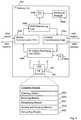
- a first network gateway with functional units configured to basically perform the above-described steps and functions of gateway 100,will now be described in more detail with reference to the schematic block diagram in Fig. 4 .
- the first gateway 400serves a first local network and is capable of enabling communication of data packets between a first communications device in the first local network and a second communications device in a second local network. Private IP addresses are used for devices present in the first and second local networks.
- the gateway 400may basically be configured to act as the server 100 in Fig's 1 and 2 and/or to execute the process shown in Fig. 3 .
- the network gateway 400is configured with a local DNS function for handling DNS requests basically in the manner described for the above examples.
- the gateway 400comprises a name server (NS) record manager 400a adapted to update a local name server record 400b with a domain name and an IP address of a second gateway 102 of the second network, each of the first and second gateways having a local DNS function.
- the gateway 400also comprises an internal communication unit 400c adapted to receive from the first device (not shown) an outgoing DNS request referring to a hostname of the second device.
- the gateway 400also comprises a DNS determining unit 400d adapted to determine the IP address of a primary DNS being the second gateway, from the local Name Server record based on a domain name in the hostname.
- the gateway 400further comprises an external communication unit 400e adapted to send a DNS request to the second gateway (not shown) using the determined IP address, and to obtain a current private IP address of the second device in a DNS response from the second gateway.
- the internal communication unit 400cis further adapted to forward a DNS response to the first device referring to the current private IP address of the second device.
- the gateway 400also comprises an IP address translating unit 400f adapted to translate the obtained private IP address to a modified private IP address used in the first network for the second device, if the private IP addresses used for devices in the first and second local networks are potentially overlapping and the obtained private IP address is used in the second network for the second device.
- the modified private IP addressmay have been defined for a VPN tunnel between the first and second networks and is separate from, i.e. non-overlapped with, an internal IP address space used in the first local network for devices in the first local network.
- the modified private IP addressmay be retrieved from a translation table 400g created in the gateway 400 and containing at least a tunnel identity and a non-overlapping IP address space used in the first network for devices present the second network.
- the functional units described abovecan be implemented as program modules of a computer program 402 comprising code means which when run on the first gateway 400 causes the first gateway to perform the above-described functions and steps of the first gateway.
- the computer program 402is carried by a computer program product 404 comprising a computer readable medium on which the computer program is stored.
- the program modules of the computer program 402include:
- the code means of the computer program 404 and computer program product 406may also cause the first gateway to perform the following functions.
- the code meansmay cause the first gateway to translate the obtained private IP address to a modified private IP address used in the first network for the second device.
- the modified private IP addressis within an address space defined for a VPN tunnel between the first and second networks and being separate from, i.e. non-overlapped with, an internal IP address space used in the first local network for devices in the first local network,
- the DNS response forwarded to the first devicewould then comprise the modified IP address.
- the code meansmay cause the first gateway to temporarily cache the current private IP address of the second device in the first gateway according to the time-out parameter.
- Fig. 4merely illustrates various exemplary functional units and program modules in the gateway 400 in a logical sense, while the skilled person is free to implement the described functions in practice using any suitable software and hardware means.
- the inventionis generally not limited to the shown structure of the gateway 400.
- the computer program productmay be a flash memory, ROM (Read-Only Memory) or an EEPROM (Electrically Erasable Programmable ROM), and the computer program modules described above could in alternative embodiments be distributed on different computer program products in the form of memories within the gateway 400.
Landscapes
- Engineering & Computer Science (AREA)
- Computer Networks & Wireless Communication (AREA)
- Signal Processing (AREA)
- Computer Security & Cryptography (AREA)
- Data Exchanges In Wide-Area Networks (AREA)
- Small-Scale Networks (AREA)
Description
- The invention relates generally to a method, computer program, computer program product and apparatus for enabling communication of data packets between communication devices located within different local networks which could use overlapping address spaces.
- Packet-based transmission of digitally encoded information between different parties over IP (Internet Protocol) networks is used for a variety of communication services, such as e-mail messaging, file transfers, Internet browsing, voice and video telephony, content streaming, games, and so forth. Digitally encoded information is arranged into data packets at a sending party which then transmits the packets towards a targeted receiving party over a transmission path. A data packet is basically configured with a data field containing payload data and a header field containing a destination address of the receiving party and a source address of the sending party.
- Data packets may be communicated between various communication devices located within different local or private networks where each network employs a gateway for receiving packets to the devices from sources outside the network, and also for sending packets from the devices to destinations outside the network. The packets communicated between such devices in different local networks are then transported between the respective network gateways over a public IP network, such as the Internet.
- In this description, the term "local network" is used to generally represent any network using internal private addressing and a gateway for external communication with parties outside the network. Other commonly used equivalent terms include "private network", "residential network" and "home network". Further, a "gateway" could be a residential gateway (RGW), an IP router or any other type of network entity capable of communicating data packets between a device within a local network and an entity outside the network. The term "device" is further used here to represent any terminal, computer, telephone or server capable of communicating data packets with other devices.
- Since communication over public IP networks is generally deemed "unsafe" with respect to data protection and privacy, it is desirable to protect payload data and other sensitive information in the packets from illicit interception or manipulation. One way of overcoming this problem is to establish a VPN (Virtual Private Network) tunnel between the communicating parties over the public IP network.
- A VPN can be seen basically as an encrypted tunnel through a public IP network, for transferring data packets between terminals and servers. VPNs are commonly used for secure communications through the public Internet. Various QoS (Quality of Service) parameters may be defined for a VPN to achieve expected behaviour between a VPN customer and a VPN service provider. Generally, a VPN may be established for two or more communication devices in a user community to provide a certain functionality that is in some respect relevant to that community.
- As the popularity and usage of the Internet grows, it becomes increasingly desirable to extend private and local networks across the Internet as well. For example, many companies and enterprises having a local network establish their own VPNs to allow their employees to access the local network remotely.
- A VPN can thus be seen as a logical and "distributed" local network running over a public network infrastructure. These networks make use of a range of technologies to obtain traffic privacy, traffic separation and QoS of the data. A VPN can be established over an intranet, the Internet or a service provider's network infrastructure. There are generally two basic types of VPN services available referred to as "Access VPNs" and "LAN (Local Area Network)-to-LAN VPNs", the former being used for remote access and the latter when different local networks are interconnected to provide an intranet or extranet.
- Devices within local networks typically use IP-addresses from a private address space, where such private IP addresses can be freely assigned to devices internally by a local administrator or the like. The used private IP-addresses are thus basically unknown to other users, unless explicitly told, and also to the Internet service provider providing public IP-addresses to subscribers.
- Today, these private address spaces are generally re-used in multiple local networks, and therefore the private IP-addresses used by different local networks for their devices may overlap with each other, in particular the commonly used IPv4-based private address spaces. For example, the private IP address used by a device in one local network may be the same address as the one used by another device in another opposite local network, resulting in ambiguous addressing in communicated data packets. Due to such overlapping or re-used private address spaces and local assignment to devices, private IP addresses are effectively "unroutable" in the public Internet, and public IP addresses must therefore also be used in the packets since private IP addresses are not used for routing outside the local network domain.
- A remaining problem is however that a packet sending device in one local network must include a private IP address of a receiving device in the opposite local network, which requires some suitable functionality at the sending device for proper identification of the receiving device. Furthermore, if dynamic address assignment is used for the devices within the local networks, the private IP address of a particular device will be changed from time to time. Thus, it could be rather difficult to maintain knowledge at the local devices of such address changes at the opposite network to provide a proper destination address in outgoing packets.
US-2004/0148439-A1 discloses a system and method for creating a peer to peer network by interconnecting private networks via publicly addressable residential gateway. A tunnel between a gateway of a first private network and a gateway of a second private network is established and the address of a device in one of the private networks is mapped into the other private network.US-2005/0076142-A1 discloses a technique for attaching a private name space of a home network to a private name space of another home network. A name and an IP address of a remote home network are received via a VPN tunnel. The configuration of a DNS server of the local home network is updated to delegate names of the remote home network to a remote gateway.US-2003/0158962-A1 discloses a method for resolving an address conflict between a first processor in a first network and a second processor in a second network. In case of conflict, tunnel information is removed from one or more of the packets received from the first processor. Based on the removed tunnel information, the packets are associated with the conflict and a translated address is determined.- It is an object of the invention to address at least some of the problems outlined above. It is also an object to provide a mechanism for obtaining a destination address for communicating a data packet from a first device in a first local network to a second device in a second local network, without requiring that the sending device or its user has knowledge of what private IP address is currently valid for the second device.
- According to different aspects, a method, an arrangement in a gateway, a computer program and a computer program product are provided to enable communication of data packets between a first communications device in a first local network and a second communications device in a second local network, wherein private IP addresses are used for devices present in the first and second local networks. In one aspect, a method of enabling communication of data packets between a first communications device in a first local network and a second communications device in a second local network is provided, wherein private IP addresses are used for devices present in the first and second local networks which are potentially overlapping in the first and second local networks. The method comprises the following steps executed in a first gateway of the first network:
- updating a local Name Server record, in the first gateway, with a domain name and an IP address of a second gateway of the second network, each of said first and second gateways having a local DNS function,
- receiving from the first device an outgoing DNS request referring to a hostname of the second device,
- determining the IP address of a primary DNS being the second gateway, from the local Name Server record based on a domain name in said hostname,
- sending a DNS request to the second gateway, using the determined IP address, to obtain a current private IP address of the second device in a DNS response from the second gateway, wherein the obtained private IP address is used in the second network for the second device,
- translating the obtained private IP address to an IPv4-based, modified private IP address used in the first network for the second device, wherein the modified private IP address is within an address space defined for a VPN tunnel between the first and second networks and, by having a unique number in a second or third octet allocated to represent the second local network, is separate from, i.e. non-overlapped with, an internal IP address space used in the first local network for devices in the first local network, and
- forwarding a DNS response to the first device, referring to the modified private IP address of the second device and
- forwarding data packets received from the first communications device (D1), which data packets comprise the modified private IP address of the second communications device (D2) as a destination address in an internal header of the data packet, to the second gateway (102),
- In another aspect, an arrangement is provided in a first gateway which serves the first local network. The gateway arrangement comprises a name server record manager adapted to update a local name server record with a domain name and an IP address of a second gateway of the second network, where each of the first and second gateways has a local DNS function. The gateway arrangement also comprises an internal communication unit adapted to receive from the first device an outgoing DNS request referring to a hostname of the second device. The gateway arrangement also comprises a DNS determining unit adapted to determine the IP address of a primary DNS being the second gateway, from the local name server record based on a domain name in the hostname.
- The gateway arrangement also comprises an external communication unit adapted to send a DNS request to the second gateway, using the determined IP address, and to obtain a current private IP address of the second device in a DNS response from the second gateway wherein the obtained private IP address is used in the second network for the second device. The arrangement also comprises an IP address translating unit adapted to translate the obtained private IP address to an IPv4-based, modified private IP address used in the first network for the second device, wherein the modified private IP address has been defined for a VPN tunnel between the first and second networks and by having a unique number in a second or third octet allocated to represent the second local network, being separate from, i.e. non-overlapped with, an internal IP address space used in the first local network for devices in the first local network. The internal communication unit is further adapted to forward a DNS response to the first device referring to the modified private IP address of the second device.
- Data packets which are received from the first communications device, which data packets comprise the modified private IP address of the second communications device as a destination address in an internal header of the data packet, may be forwarded to the second gateway. The destination address in the internal header of the data packet is translated, from the modified private IP address to the private IP address which is used in the second local network, by the second gateway.
- In yet another aspect, a computer program is configured for a first gateway that serves a first local network. The computer program comprises code means which when run on the first gateway causes the first gateway to update a local name server record with a domain name and an IP address of a second gateway of the second network, where each of the first and second gateways has a local DNS function. The code means also causes the first gateway to receive from the first device an outgoing DNS request referring to a hostname of the second device, and to determine the IP address of a primary DNS being the second gateway, from the local name server record based on a domain name in the hostname.
- The code means also causes the first gateway to send a DNS request to the second gateway, using the determined IP address, to obtain a current private IP address of the second device in a DNS response from the second gateway, wherein the obtained private IP address is used in the second network for the second device. The code means also causes the first gateway to translate the obtained private IP address to an IPv4-based, modified private IP address used in the first network for the second device, wherein the modified private IP address is within an address space defined for a VPN tunnel between the first and second networks and, by having a unique number in a second or third octet allocated to represent the second local network, is separate from, i.e. non-overlapped with, an internal IP address space used in the first local network for devices in the first local network, and to forward a DNS response to the first device, referring to the current private IP address of the second device.
- Data packets which are received from the first communications device, which data packets comprise the modified private IP address of the second communications device as a destination address in an internal header of the data packet, may be forwarded to the second gateway. The destination address in the internal header of the data packet is translated, from the modified private IP address to the private IP address which is used in the second local network, by the second gateway.
- In yet another aspect, a computer program product comprises the computer program above and a computer readable medium on which the computer program is stored.
- Each of the above method, gateway arrangement, computer program and computer program product may further comprise features and functions configured according to the following embodiments.
- For example, the DNS response from the second gateway may contain a time-out parameter which determines a validity duration for the current private IP address of the second device. In that case, the current private IP address of the second device may be temporarily cached in the first gateway according to the time-out parameter.
- The hostname may include a first part identifying the second device and a second part with the domain name. Further, the VPN tunnel may have been established for data packet communication between the first and second gateways, and a public IP address may have been assigned to each gateway.
- Further possible features and benefits of the invention will become apparent from the detailed description below.
- The invention will now be described in more detail by means of exemplary embodiments and with reference to the accompanying drawings, in which:
Fig. 1 is a schematic block diagram illustrating a scenario and procedure for enabling communication of data packets across two different local networks, according to some exemplary embodiments.Fig. 2 is a signalling diagram illustrating how a useful IP address of a destination device in an opposite local network can be obtained, according to further exemplary embodiments.Fig. 3 is a flow chart illustrating a procedure for enabling communication of data packets between two devices in opposite local networks, according to yet another embodiment.Fig. 4 is a schematic block diagram illustrating in more detail a network gateway equipped with a local DNS function, according to further exemplary embodiments.- The invention provides a mechanism for obtaining a useful destination address for communicating a data packet from a first device in a first local network to a second device in a second local network, without requiring that the sending device or its user has knowledge of what private IP address is currently valid for the second device. This mechanism is useful, e.g., when potentially overlapping address spaces are used in the first and second networks which may require address translation to ensure unambiguous addressing of packets within the networks, and particularly when private IP addresses are assigned to local devices on a dynamic basis such that the individual devices change their addresses frequently.
- In this solution, the first device can simply refer to a hostname of the second device in an outgoing DNS request, which is then sent from a first gateway of the first network to a second gateway of the second network, each gateway having a local DNS function for handling DNS requests. The first gateway then receives a DNS response from the second gateway containing the currently valid private IP address of the second device used in the second network, and a DNS response referring to that address is also forwarded to the first device. Thereby, the first device is able to get across data packets to the second device using the currently valid private IP address of the second device as a destination address in a header field of the packet.
- The IP address in the DNS response is thus used in the second network for the second device, and can also be used in the first network if it is known that the address space used in the second network does not overlap with the address space used in the first network. In that case, the DNS response to the first device includes the received IP address "as is".
- On the other hand, if potentially overlapping address spaces are used for devices in the first and second local networks, the first gateway preferably translates the received private IP address into a private IP address used in the first network for the second device and which is separate from, i.e. non-overlapping with, the private IP address space used for the local devices within the first network. In that case, the DNS response to the first device includes the translated IP address.
- An example of how the above can be accomplished will now be described with reference to a communication scenario shown in
Fig. 1 . Afirst gateway 100 and asecond gateway 102 are shown serving first and second networks A and B, respectively, where a plurality of devices are present including a first device D1 in network A and a second device D2 in network B. It is assumed that a private address space is used in each local network A, B for internal communication of its devices. In this example, the private IP address spaces used in the two networks may potentially overlap with each other since such address spaces are often widely re-used in numerous local networks, in general. - Each
gateway record 100a is stored, or "updated", in thefirst gateway 100 and includes a domain name and an IP address of thesecond gateway 102. For example, users of the local networks A and B may have agreed to set up a VPN tunnel between the networks to enable "safe" communication of data packets between devices in the opposite networks over a public IP network such as the Internet. Step 1:1 would then be made in preparation for communication via the VPN tunnel. - At some point later, a user of device D1 wants to communicate with a user of device D2, and in this solution it is not necessary that the IP address of device D2 is known to the user/device D1. The user of D1 can simply input a hostname of the device D2 to trigger a DNS request from device D1. In a nextstep 1:2, device D1 thus sends the DNS request to the
first gateway 100 referring to the hostname of device D2 that includes a first part identifying the second device and a second part with a domain name identifying thesecond gateway 102 and network B. - In a followingstep 1:3,
gateway 100 checks theNS record 100a to determine the IP address of a so-called "primary DNS" of that domain name, in this case being thesecond gateway 102. This IP address was stored in theNS record 100a in step 1:1, and can thus be retrieved therefrom.Gateway 100 then sends another DNS request to thesecond gateway 102, using the determined IP address and referring to the hostname of device D2, in a furtherstep 1:4.Gateway 102 then replies with a DNS response containing a private IP address that is currently valid for the second device D2, in a nextstep 1:5. - At this point, different options are possible depending on the situation. If the address spaces used in the two local networks A and B are potentially overlapping, there is a potential risk that the received IP address of device D2 may be confused with the locally used IP addresses of devices within network A. In that case, each
gateway gateway 100 therefore translates the IP address used in network B for device D2 into an IP address used in network A for device D2, in a furtherstep 1:6, the latter address being taken from the IP address space previously defined bygateway 100 for devices in network B. - On the other hand, if the address spaces used in the two local networks A and B are known to be separate from each other, i.e. non-overlapping, the private IP address of device D2 in the received DNS response will be unique in network A as well and no translation will therefore be necessary. Step 1:6 can then be omitted.
- Having received the IP address of device D2 in the DNS response of step 1:5,
gateway 100 may also cache D2's address in a local storage or the like, as illustrated by a further optionalstep 1:7. In one embodiment, the DNS response fromgateway 102 contains a time-out parameter which determines a validity duration for the current private IP address of device D2. That IP address may then be temporarily cached in the first gateway according to the time-out parameter. - Finally,
gateway 100 forwards a DNS response to the device D1 in astep 1:8, containing the current private IP address of device D2, possibly translated according to the above. Thereby, device D1 is able to get across data packets to device D2, by using the received IP address of D2 as a destination address. If a VPN tunnel has been established for data packet communication betweengateways Fig. 2 illustrates an example of message communication, by means of a signalling diagram, involving the first device D1,first gateway 100 andsecond gateway 102 according to the procedure shown inFig. 1 . It is assumed that the NS record ofgateway 100 has been updated with domain name and IP address ofgateway 102, as described for step 1:1 above. It is also assumed that the private IP address space 10.0.0.0/24 is used in network A for its own local devices within network A.- In a first shownstep 2:1,
gateway 100 receives the DNS request from device D1 referring to the hostname of device D2, in this caseD2.networkB.dyndns.org. This hostname includes a first part "D2" identifying the target device D2 and a second part "networkB.dyndns.org" being a domain name identifying thesecond gateway 102 and network B. It should be noted that the first part may be freely configured in any manner, e.g. "Dx", "www" or "mail", which is agreed and predefined for the device in beforehand between the two networks A and B. - In a nextstep 2:2,
gateway 100 determines the primary DNS by checking the NS record for the domain "networkB.dyndns.org", as described for step 1:3 above, and thereby obtains the IP address ofgateway 102.Gateway 100 is now able to send a DNS request to the obtained IP address, i.e. togateway 102, in a followingstep 2:3, referring to the above hostname. Upon receiving the DNS request,gateway 102 resolves the hostname according to a regular procedure, in a nextstep 2:4, to determine the private IP address 10.0.0.10 of device D2 which is valid in network B but not in network A in this example. Gateway 102 then sends a DNS response togateway 102, in a furtherstep 2:5, containing the private IP address 10.0.0.10 of device D2 presented as payload in a DNS response packet. Since potentially overlapping address spaces are used in networks A and B,gateway 100 translates the received IP address 10.0.0.10, in a nextstep 2:6, into a modified private IP address 10.0.1.10 which has been assigned to the second device for use in the first network. The new translated address is separate from, i.e. non-overlapping with, the private IP address space used for the local devices within the first network.- In this example, the modified private IP address is an IPv4-based address where a unique number in a third octet has been allocated to represent the opposite network B, in this case "1". However, any addressing scheme may be used in network A for devices in network B and the invention is not limited in this respect. The modified IP address of device D2 may also be cached in the
gateway 100, as indicated by an optionalstep 2:7. - Gateway then sends a DNS response to device D1, in a furtherstep 2:8, containing the translated IP address 10.0.1.10 of device D2 presented as payload in a DNS response packet. Also device D1 may cache the received address in a local storage, as indicated by another optionalstep 2:9. Device D1 is now able to get across data packets to device D2, by using the received IP address of D2 as a destination address in an internal header of packets from D1 to D2, as shown in a furtherstep 2:10.
Gateway 102 will then translate the destination address from 10.0.1.10 to 10.0.0.10 which is valid in network B for device D2, as shown in a finalstep 2:11. - A procedure, performed by a first gateway in a first local network in which a first device is present, for enabling packet communication with a second device in an opposite second local network, will now be briefly described with reference to the flow chart in
Fig. 3 . As similar to the examples described above, the first gateway and a second gateway in the second local network are equipped with a DNS function. - In a
firststep 300, a local NS record in the first gateway is updated by storing a domain name and public IP address of the second gateway. In anextstep 302, an outgoing DNS request is received from the first device, the DNS request referring to a hostname of the second device. In a followingstep 304, a public IP address of a primary DNS being the second gateway is determined by checking the local NS record. A DNS request is then sent to the second gateway, in afurtherstep 306, to obtain a current private IP address used in the second network for the second device. - As mentioned for the above examples, it may be necessary to translate the obtained IP address of the second device if potentially overlapping address spaces are used in the two networks. Thus, in a
step 308, the process may diverge depending on whether there is a risk that such overlapping address spaces are used in the first and second networks for their own devices. If it is known that they do not use such overlapping address spaces, the IP address of the second device obtained instep 306 can be used unambiguously in the first network, and the IP address could be forwarded in a DNS response to the first device as obtained, i.e. without translation, in astep 310. - Otherwise, the obtained IP address is translated into a modified private IP address which has been assigned to the second device for use in the first network, in a
step 312. The translated and modified IP address is then finally forwarded in a DNS response to the first device in a final shownstep 314. - The exemplary procedure in
Fig. 3 may be somewhat modified depending on the implementation. In a practical example, the obtained IP address may be translated into a modified private IP address according to the above, regardless of whether there is a risk or not that the two networks use overlapping address spaces. In that case, steps 308 and 310 could be omitted andsteps step 306. - A first network gateway with functional units configured to basically perform the above-described steps and functions of
gateway 100, will now be described in more detail with reference to the schematic block diagram inFig. 4 . In this example, thefirst gateway 400 serves a first local network and is capable of enabling communication of data packets between a first communications device in the first local network and a second communications device in a second local network. Private IP addresses are used for devices present in the first and second local networks. - The
gateway 400 may basically be configured to act as theserver 100 in Fig's 1 and 2 and/or to execute the process shown inFig. 3 . In particular, thenetwork gateway 400 is configured with a local DNS function for handling DNS requests basically in the manner described for the above examples. - The
gateway 400 comprises a name server (NS)record manager 400a adapted to update a localname server record 400b with a domain name and an IP address of asecond gateway 102 of the second network, each of the first and second gateways having a local DNS function. Thegateway 400 also comprises aninternal communication unit 400c adapted to receive from the first device (not shown) an outgoing DNS request referring to a hostname of the second device. Thegateway 400 also comprises aDNS determining unit 400d adapted to determine the IP address of a primary DNS being the second gateway, from the local Name Server record based on a domain name in the hostname. - The
gateway 400 further comprises anexternal communication unit 400e adapted to send a DNS request to the second gateway (not shown) using the determined IP address, and to obtain a current private IP address of the second device in a DNS response from the second gateway. Theinternal communication unit 400c is further adapted to forward a DNS response to the first device referring to the current private IP address of the second device. - The
gateway 400 also comprises an IPaddress translating unit 400f adapted to translate the obtained private IP address to a modified private IP address used in the first network for the second device, if the private IP addresses used for devices in the first and second local networks are potentially overlapping and the obtained private IP address is used in the second network for the second device. In that case, the modified private IP address may have been defined for a VPN tunnel between the first and second networks and is separate from, i.e. non-overlapped with, an internal IP address space used in the first local network for devices in the first local network. Further, the modified private IP address may be retrieved from a translation table 400g created in thegateway 400 and containing at least a tunnel identity and a non-overlapping IP address space used in the first network for devices present the second network. - As further illustrated in
Fig. 4 , the functional units described above can be implemented as program modules of acomputer program 402 comprising code means which when run on thefirst gateway 400 causes the first gateway to perform the above-described functions and steps of the first gateway. In this embodiment, thecomputer program 402 is carried by acomputer program product 404 comprising a computer readable medium on which the computer program is stored. - The program modules of the
computer program 402 include: - an
updating module 402a capable of updating the localname server record 400b with a domain name and an IP address of the second gateway of the second network, each of the first and second gateways having a local DNS function, - a
receiving module 402b capable of receiving from the first device an outgoing DNS request referring to a hostname of the second device, - a determining
module 402c capable of determining the IP address of a primary DNS being the second gateway, from the local Name Server record based on a domain name in the hostname, - a sending and obtaining
module 402d capable of sending a DNS request to the second gateway, using the determined IP address, and obtain a current private IP address of the second device in a DNS response from the second gateway, and - a
forwarding module 402e capable of forwarding a DNS response to the first device, referring to the current private IP address of the second device. - The code means of the
computer program 404 and computer program product 406 may also cause the first gateway to perform the following functions. - If the private IP addresses used for devices in the first and second local networks are potentially overlapping, and the obtained private IP address is used in the second network for the second device, the code means may cause the first gateway to translate the obtained private IP address to a modified private IP address used in the first network for the second device. The modified private IP address is within an address space defined for a VPN tunnel between the first and second networks and being separate from, i.e. non-overlapped with, an internal IP address space used in the first local network for devices in the first local network, The DNS response forwarded to the first device would then comprise the modified IP address.
- If the DNS response from the second gateway further contains a time-out parameter which determines a validity duration for the current private IP address of the second device, the code means may cause the first gateway to temporarily cache the current private IP address of the second device in the first gateway according to the time-out parameter.
- It should be noted that
Fig. 4 merely illustrates various exemplary functional units and program modules in thegateway 400 in a logical sense, while the skilled person is free to implement the described functions in practice using any suitable software and hardware means. Thus, the invention is generally not limited to the shown structure of thegateway 400. For example, the computer program product may be a flash memory, ROM (Read-Only Memory) or an EEPROM (Electrically Erasable Programmable ROM), and the computer program modules described above could in alternative embodiments be distributed on different computer program products in the form of memories within thegateway 400. - The following benefits and advantages may be obtained by means of the above-described embodiments:
- 1) This solution allows users in local networks to have secure and private communication across the networks.
- 2) The DNS translation allows for a more user-friendly function not requiring knowledge of the current IP address of the opposite device.
- 3) All private IP-addresses are made unique when communicating data packets between the networks.
- 4) The translation in the payload of the DNS responses allows for better interworking between local networks having established a VPN tunnel.
- 5) The solution is scalable since each gateway is responsible for the tunneling and address translation functionalities.
- 6) The local DNS functionality does not impact or interfere with the existing global DNS functions.
- 7) The solution can also be used to support multi country solutions for mobile networks.
Claims (12)
- A method of enabling communication of data packets between a first communications device (D1) in a first local network and a second communications device (D2) in a second local network, wherein private IP addresses are used for devices present in the first and second local networks which are potentially overlapping in the first and second local networks, comprising the following steps executed in a first gateway (100) of the first network:- updating (300) a local Name Server record (100a), in the first gateway, with a domain name and an IP address of a second gateway (102) of the second network, each of said first and second gateways having a local DNS function,- receiving (302) from the first device an outgoing DNS request referring to a hostname of the second device,- determining (304) the IP address of a primary DNS being the second gateway, from the local Name Server record based on a domain name in said hostname,- sending (306) a DNS request to the second gateway, using the determined IP address, to obtain a current private IP address of the second device in a DNS response from the second gateway, wherein the obtained private IP address is used in the second network for the second device,- translating (312) the obtained private IP address to an IPv4-based, modified private IP address used in the first network for the second device, wherein the modified private IP address is within an address space defined for a VPN tunnel between the first and second networks and, by having a unique number in a second or third octet allocated to represent the second local network, is separate from, i.e., non-overlapped with, an internal IP address space used in the first local network for devices in the first local network,- forwarding (310) a DNS response to the first device, referring to the modified private IP address of the second device, and- forwarding data packets received from the first communications device (D1), which data packets comprise the modified private IP address of the second communications device (D2) as a destination address in an internal header of the data packet, to the second gateway (102),characterized in that the destination address in the internal header of the data packet is translated, from the modified private IP address to the private IP address which is used in the second local network, by the second gateway (102).
- A method according to claim 1, wherein the DNS response from the second gateway further contains a time-out parameter which determines a validity duration for the current private IP address of the second device.
- A method according to claim 2, wherein the current private IP address of the second device is temporarily cached in the first gateway according to the time-out parameter.
- A method according to any of claims 1-3, wherein the hostname includes a first part identifying the second device and a second part with said domain name.
- A method according to any of claims 1-4, wherein the VPN tunnel has been established for data packet communication between the first and second gateways (100,102), and a public IP address has been assigned to each gateway.
- An arrangement in a first gateway (100,400) serving a first local network, capable of enabling communication of data packets between a first communications device (D1) in the first local network and a second communications device (D2) in a second local network, wherein private IP addresses are used for devices present in the first and second local networks which are potentially overlapping in the first and second local networks, comprising:- a Name Server record manager (400a) adapted to update a local Name Server record (400b) with a domain name and an IP address of a second gateway (102) of the second network, each of said first and second gateways having a local DNS function,- an internal communication unit (400c) adapted to receive from the first device an outgoing DNS request referring to a hostname of the second device,- a DNS determining unit (400d) adapted to determine the IP address of a primary DNS being the second gateway, from the local Name Server record based on a domain name in said hostname,- an external communication unit (400e) adapted to send a DNS request to the second gateway, using the determined IP address, and to obtain a current private IP address of the second device in a DNS response from the second gateway, wherein the obtained private IP address is used in the second network for the second device,- an IP address translating unit (400f) adapted to translate the obtained private IP address to an IPv4-based, modified private IP address used in the first network for the second device, wherein the modified private IP address has been defined for a VPN tunnel between the first and second networks and by having a unique number in a second or third octet allocated to represent the second local network, being separate from, i.e., non-overlapped with, an internal IP address space used in the first local network for devices in the first local network,- the internal communication unit (400c) being further adapted to forward a DNS response to the first device referring to the modified private IP address of the second device, and- the internal communication unit (400c) and the external communication unit (400e) being further adapted to forward data packets received from the first communications device (D1), which data packets comprise the modified private IP address of the second communications device (D2) as a destination address in an internal header of the data packet, to the second gateway (102),characterized in that the destination address in the internal header of the data packet is translated, from the modified private IP address to the private IP address which is used in the second local network, by the second gateway (102).
- An arrangement according to claim 6, wherein the DNS response from the second gateway further contains a time-out parameter which determines a validity duration for the current private IP address of the second device.
- An arrangement according to claim 7, adapted to temporarily cache the modified private IP address according to the time-out parameter.
- An arrangement according to any of claims 6-8, wherein the hostname includes a first part identifying the second device and a second part with said domain name.
- An arrangement according to any of claims 6-9, wherein the VPN tunnel has been established for data packet communication between the first and second gateways (100,102), and a public IP address has been assigned to each gateway.
- A computer program (404) configured for a first gateway (A) serving a first local network, the computer program being capable of enabling communication of data packets between a first communications device (D1) in the first local network and a second communications device (D2) in a second local network, wherein private IP addresses are used for devices present in the first and second local networks which are potentially overlapping in the first and second local networks,
wherein the computer program comprises code means which when run on the first gateway causes the first gateway to:- update (300) a local Name Server record (100a) with a domain name and an IP address of a second gateway (102) of the second network, each of said first and second gateways having a local DNS function,- receive (302) from the first device an outgoing DNS request referring to a hostname of the second device,- determine (304) the IP address of a primary DNS being the second gateway, from the local Name Server record based on a domain name in said hostname,- send (306) a DNS request to the second gateway, using the determined IP address, to obtain a current private IP address of the second device in a DNS response from the second gateway, wherein the obtained private IP address is used in the second network for the second device,- translate (312) the obtained private IP address to an IPv4-based, modified private IP address used in the first network for the second device, wherein the modified private IP address is within an address space defined for a VPN tunnel between the first and second networks and, by having a unique number in a second or third octet allocated to represent the second local network, is separate from, i.e., non-overlapped with, an internal IP address space used in the first local network for devices in the first local network,- forward (310) a DNS response to the first device, referring to the modified private IP address of the second device, and- forward data packets received from the first communications device (D1), which data packets comprise the modified private IP address of the second communications device (D2) as a destination address in an internal header of the data packet, to the second gateway (102),characterized in that the destination address in the internal header of the data packet is translated, from the modified private IP address to the private IP address which is used in the second local network, by the second gateway (102). - A computer program product comprising a computer program according to claim 11 and a computer readable medium on which the computer program is stored.
Applications Claiming Priority (2)
| Application Number | Priority Date | Filing Date | Title |
|---|---|---|---|
| US3819208P | 2008-03-20 | 2008-03-20 | |
| PCT/SE2009/050297WO2009116948A1 (en) | 2008-03-20 | 2009-03-20 | Method and apparatus for communication of data packets between local networks |
Publications (3)
| Publication Number | Publication Date |
|---|---|
| EP2253124A1 EP2253124A1 (en) | 2010-11-24 |
| EP2253124A4 EP2253124A4 (en) | 2011-05-11 |
| EP2253124B1true EP2253124B1 (en) | 2016-03-16 |
Family
ID=41091161
Family Applications (2)
| Application Number | Title | Priority Date | Filing Date |
|---|---|---|---|
| EP09721812.7ANot-in-forceEP2253124B1 (en) | 2008-03-20 | 2009-03-20 | Method and apparatus for communication of data packets between local networks |
| EP20090721670ActiveEP2253123B1 (en) | 2008-03-20 | 2009-03-20 | Method and apparatus for communication of data packets between local networks |
Family Applications After (1)
| Application Number | Title | Priority Date | Filing Date |
|---|---|---|---|
| EP20090721670ActiveEP2253123B1 (en) | 2008-03-20 | 2009-03-20 | Method and apparatus for communication of data packets between local networks |
Country Status (6)
| Country | Link |
|---|---|
| US (2) | US8559448B2 (en) |
| EP (2) | EP2253124B1 (en) |
| JP (2) | JP2011515944A (en) |
| ES (1) | ES2429121T3 (en) |
| IL (2) | IL207903A (en) |
| WO (2) | WO2009116948A1 (en) |
Families Citing this family (109)
| Publication number | Priority date | Publication date | Assignee | Title |
|---|---|---|---|---|
| US8160255B2 (en)* | 2006-04-24 | 2012-04-17 | Cisco Technology, Inc. | System and method for encrypted group network communication with point-to-point privacy |
| US8625610B2 (en)* | 2007-10-12 | 2014-01-07 | Cisco Technology, Inc. | System and method for improving spoke to spoke communication in a computer network |
| CN101952810B (en)* | 2007-10-24 | 2013-10-30 | 兰特罗尼克斯公司 | Various methods and devices for assigning virtual IP addresses by central station |
| US8346961B2 (en) | 2007-12-12 | 2013-01-01 | Cisco Technology, Inc. | System and method for using routing protocol extensions for improving spoke to spoke communication in a computer network |
| US8837491B2 (en) | 2008-05-27 | 2014-09-16 | Glue Networks | Regional virtual VPN |
| KR20100040658A (en)* | 2008-10-10 | 2010-04-20 | 삼성전자주식회사 | Method and apparatus for preventing ip address conflict in remote access service of upnp network |
| US9319300B2 (en)* | 2008-12-09 | 2016-04-19 | Glue Networks, Inc. | Systems and methods for determining endpoint configurations for endpoints of a virtual private network (VPN) and deploying the configurations to the endpoints |
| US8726007B2 (en)* | 2009-03-31 | 2014-05-13 | Novell, Inc. | Techniques for packet processing with removal of IP layer routing dependencies |
| EP2436167A1 (en)* | 2009-05-29 | 2012-04-04 | Telefonaktiebolaget LM Ericsson (publ) | Content sharing system performance improvement |
| US8687631B2 (en)* | 2009-10-16 | 2014-04-01 | Cisco Technology, Inc. | System and method for providing a translation mechanism in a network environment |
| US20110103384A1 (en)* | 2009-10-29 | 2011-05-05 | Sierra Wireless, Inc. | Routing device and method of configuration for network name resolution of same |
| JP5357707B2 (en)* | 2009-11-11 | 2013-12-04 | 株式会社日立製作所 | Gateway device and port number assigning method |
| JP5260487B2 (en)* | 2009-12-28 | 2013-08-14 | 日本電信電話株式会社 | Address determination device, address determination method, and address determination program |
| JP5569697B2 (en)* | 2011-03-09 | 2014-08-13 | 村田機械株式会社 | Relay server and relay communication system |
| JP5452527B2 (en)* | 2011-03-11 | 2014-03-26 | エヌ・ティ・ティ・コムウェア株式会社 | Address management device, address management method, and address management program |
| JP5552460B2 (en)* | 2011-04-13 | 2014-07-16 | 日本電信電話株式会社 | Inter-base connection system, inter-base connection method, address conversion information generation apparatus, address conversion information generation method, and program |
| CN102333022B (en)* | 2011-05-31 | 2014-01-15 | 广东省电力调度中心 | Method for interacting cross-safety protection region information in power communication network and protection system |
| AU2012282841B2 (en) | 2011-07-08 | 2016-03-31 | Virnetx, Inc. | Dynamic VPN address allocation |
| US12323272B2 (en) | 2011-09-09 | 2025-06-03 | Primes Lab Inc. | Private matter gateway connection mechanism for use in a private communication architecture |
| US20230254292A1 (en)* | 2011-09-09 | 2023-08-10 | Primes Lab Inc. | Private and Secure Chat Connection Mechanism for Use in a Private Communication Architecture |
| EP2787692B1 (en)* | 2011-11-30 | 2019-02-27 | Murata Machinery, Ltd. | Relay server with control unit adapted to set an overlap detection condition |
| US10044582B2 (en)* | 2012-01-28 | 2018-08-07 | A10 Networks, Inc. | Generating secure name records |
| US8954964B2 (en)* | 2012-02-27 | 2015-02-10 | Ca, Inc. | System and method for isolated virtual image and appliance communication within a cloud environment |
| US8930493B2 (en) | 2012-03-20 | 2015-01-06 | International Business Machines Corporation | Inter-domain replication of service information |
| CN102647482B (en)* | 2012-03-31 | 2015-05-06 | 北京奇虎科技有限公司 | Method and system for accessing website |
| TWI482469B (en)* | 2012-05-23 | 2015-04-21 | Gemtek Technology Co Ltd | Routing device |
| US9276847B2 (en) | 2013-01-02 | 2016-03-01 | Acceleration Systems, LLC | Systems and methods for providing a ReNAT virtual private network |
| EP3779712A1 (en)* | 2013-01-02 | 2021-02-17 | Skycasters, LLC | Systems and methods for providing a renat communications environment |
| US9760528B1 (en) | 2013-03-14 | 2017-09-12 | Glue Networks, Inc. | Methods and systems for creating a network |
| US9722918B2 (en) | 2013-03-15 | 2017-08-01 | A10 Networks, Inc. | System and method for customizing the identification of application or content type |
| US9928082B1 (en) | 2013-03-19 | 2018-03-27 | Gluware, Inc. | Methods and systems for remote device configuration |
| JP5997367B2 (en)* | 2013-03-26 | 2016-09-28 | Kddi株式会社 | Transfer device |
| EP3021555B1 (en)* | 2013-07-12 | 2018-09-12 | Huawei Technologies Co., Ltd. | Message processing method and device |
| US9887960B2 (en) | 2013-08-14 | 2018-02-06 | Nicira, Inc. | Providing services for logical networks |
| US9952885B2 (en) | 2013-08-14 | 2018-04-24 | Nicira, Inc. | Generation of configuration files for a DHCP module executing within a virtualized container |
| US9503371B2 (en) | 2013-09-04 | 2016-11-22 | Nicira, Inc. | High availability L3 gateways for logical networks |
| US9577845B2 (en) | 2013-09-04 | 2017-02-21 | Nicira, Inc. | Multiple active L3 gateways for logical networks |
| CN105658377A (en)* | 2013-10-04 | 2016-06-08 | 福吉米株式会社 | Polishing device and polishing method |
| US10063458B2 (en) | 2013-10-13 | 2018-08-28 | Nicira, Inc. | Asymmetric connection with external networks |
| JP6894060B2 (en)* | 2014-02-06 | 2021-06-23 | イー^ナット テクノロジーズ リミティド ライアビリティ カンパニー | Systems and methods that provide a composite secure link architecture |
| MX364546B (en)* | 2014-02-06 | 2019-04-30 | Acceleration Systems Llc | Systems and methods for providing a multiple secure link architecture. |
| US9419855B2 (en) | 2014-03-14 | 2016-08-16 | Nicira, Inc. | Static routes for logical routers |
| US9590901B2 (en) | 2014-03-14 | 2017-03-07 | Nicira, Inc. | Route advertisement by managed gateways |
| US9225597B2 (en) | 2014-03-14 | 2015-12-29 | Nicira, Inc. | Managed gateways peering with external router to attract ingress packets |
| US9647883B2 (en) | 2014-03-21 | 2017-05-09 | Nicria, Inc. | Multiple levels of logical routers |
| WO2015147943A1 (en)* | 2014-03-27 | 2015-10-01 | Nicira, Inc. | Distributed network address translation for cloud service access |
| US9338091B2 (en) | 2014-03-27 | 2016-05-10 | Nicira, Inc. | Procedures for efficient cloud service access in a system with multiple tenant logical networks |
| US9825854B2 (en)* | 2014-03-27 | 2017-11-21 | Nicira, Inc. | Host architecture for efficient cloud service access |
| US9794186B2 (en) | 2014-03-27 | 2017-10-17 | Nicira, Inc. | Distributed network address translation for efficient cloud service access |
| US9906422B2 (en) | 2014-05-16 | 2018-02-27 | A10 Networks, Inc. | Distributed system to determine a server's health |
| US11533255B2 (en) | 2014-11-14 | 2022-12-20 | Nicira, Inc. | Stateful services on stateless clustered edge |
| US9876714B2 (en) | 2014-11-14 | 2018-01-23 | Nicira, Inc. | Stateful services on stateless clustered edge |
| US10044617B2 (en) | 2014-11-14 | 2018-08-07 | Nicira, Inc. | Stateful services on stateless clustered edge |
| US9866473B2 (en) | 2014-11-14 | 2018-01-09 | Nicira, Inc. | Stateful services on stateless clustered edge |
| US9787605B2 (en) | 2015-01-30 | 2017-10-10 | Nicira, Inc. | Logical router with multiple routing components |
| US9785412B1 (en) | 2015-02-27 | 2017-10-10 | Glue Networks, Inc. | Methods and systems for object-oriented modeling of networks |
| US10038628B2 (en) | 2015-04-04 | 2018-07-31 | Nicira, Inc. | Route server mode for dynamic routing between logical and physical networks |
| WO2017006833A1 (en)* | 2015-07-06 | 2017-01-12 | アイコム株式会社 | Relay device, communication packet relay method, and sound communication system |
| US10129142B2 (en) | 2015-08-11 | 2018-11-13 | Nicira, Inc. | Route configuration for logical router |
| US10057157B2 (en) | 2015-08-31 | 2018-08-21 | Nicira, Inc. | Automatically advertising NAT routes between logical routers |
| US9787581B2 (en) | 2015-09-21 | 2017-10-10 | A10 Networks, Inc. | Secure data flow open information analytics |
| US10095535B2 (en) | 2015-10-31 | 2018-10-09 | Nicira, Inc. | Static route types for logical routers |
| CN105681486B (en)* | 2016-01-15 | 2018-11-23 | 华洋通信科技股份有限公司 | A kind of across broadcast domain data communications method of XinIP |
| EP3223494A1 (en)* | 2016-03-21 | 2017-09-27 | Thomson Licensing | Method and apparatus for interconnection between networks |
| US10333849B2 (en) | 2016-04-28 | 2019-06-25 | Nicira, Inc. | Automatic configuration of logical routers on edge nodes |
| US10484515B2 (en) | 2016-04-29 | 2019-11-19 | Nicira, Inc. | Implementing logical metadata proxy servers in logical networks |
| US10841273B2 (en) | 2016-04-29 | 2020-11-17 | Nicira, Inc. | Implementing logical DHCP servers in logical networks |
| US10091161B2 (en) | 2016-04-30 | 2018-10-02 | Nicira, Inc. | Assignment of router ID for logical routers |
| US10560320B2 (en) | 2016-06-29 | 2020-02-11 | Nicira, Inc. | Ranking of gateways in cluster |
| US10153973B2 (en) | 2016-06-29 | 2018-12-11 | Nicira, Inc. | Installation of routing tables for logical router in route server mode |
| US10812348B2 (en) | 2016-07-15 | 2020-10-20 | A10 Networks, Inc. | Automatic capture of network data for a detected anomaly |
| US10341118B2 (en) | 2016-08-01 | 2019-07-02 | A10 Networks, Inc. | SSL gateway with integrated hardware security module |
| US10454758B2 (en) | 2016-08-31 | 2019-10-22 | Nicira, Inc. | Edge node cluster network redundancy and fast convergence using an underlay anycast VTEP IP |
| US10341236B2 (en) | 2016-09-30 | 2019-07-02 | Nicira, Inc. | Anycast edge service gateways |
| US10382562B2 (en) | 2016-11-04 | 2019-08-13 | A10 Networks, Inc. | Verification of server certificates using hash codes |
| US10250475B2 (en) | 2016-12-08 | 2019-04-02 | A10 Networks, Inc. | Measurement of application response delay time |
| US10237123B2 (en) | 2016-12-21 | 2019-03-19 | Nicira, Inc. | Dynamic recovery from a split-brain failure in edge nodes |
| US10742746B2 (en) | 2016-12-21 | 2020-08-11 | Nicira, Inc. | Bypassing a load balancer in a return path of network traffic |
| US10212071B2 (en) | 2016-12-21 | 2019-02-19 | Nicira, Inc. | Bypassing a load balancer in a return path of network traffic |
| US10616045B2 (en) | 2016-12-22 | 2020-04-07 | Nicira, Inc. | Migration of centralized routing components of logical router |
| US10397270B2 (en) | 2017-01-04 | 2019-08-27 | A10 Networks, Inc. | Dynamic session rate limiter |
| US10187377B2 (en) | 2017-02-08 | 2019-01-22 | A10 Networks, Inc. | Caching network generated security certificates |
| US10425330B2 (en)* | 2017-04-24 | 2019-09-24 | International Business Machines Corporation | Routing packets in multiple destination networks with overlapping address spaces |
| US10681000B2 (en)* | 2017-06-30 | 2020-06-09 | Nicira, Inc. | Assignment of unique physical network addresses for logical network addresses |
| US10637800B2 (en) | 2017-06-30 | 2020-04-28 | Nicira, Inc | Replacement of logical network addresses with physical network addresses |
| US11570092B2 (en) | 2017-07-31 | 2023-01-31 | Nicira, Inc. | Methods for active-active stateful network service cluster |
| US10951584B2 (en) | 2017-07-31 | 2021-03-16 | Nicira, Inc. | Methods for active-active stateful network service cluster |
| US11296984B2 (en) | 2017-07-31 | 2022-04-05 | Nicira, Inc. | Use of hypervisor for active-active stateful network service cluster |
| US10104039B1 (en) | 2017-09-28 | 2018-10-16 | Cloudflare, Inc. | Establishing and using a tunnel from an origin server in a distributed edge compute and routing service |
| US20190104105A1 (en)* | 2017-10-04 | 2019-04-04 | Harris Solutions NY, Inc. | Systems and methods for creating a virtual layer 2 network through tethering |
| CN109962989B (en)* | 2017-12-25 | 2022-03-01 | 中国电信股份有限公司 | Method, device and system for traversing network address gateway |
| US11153122B2 (en) | 2018-02-19 | 2021-10-19 | Nicira, Inc. | Providing stateful services deployed in redundant gateways connected to asymmetric network |
| US10708125B1 (en)* | 2018-09-05 | 2020-07-07 | Amazon Technologies, Inc. | Gateway configuration using a network manager |
| US10931560B2 (en) | 2018-11-23 | 2021-02-23 | Vmware, Inc. | Using route type to determine routing protocol behavior |
| US10797998B2 (en) | 2018-12-05 | 2020-10-06 | Vmware, Inc. | Route server for distributed routers using hierarchical routing protocol |
| US10938788B2 (en) | 2018-12-12 | 2021-03-02 | Vmware, Inc. | Static routes for policy-based VPN |
| CN111698338B (en) | 2019-03-15 | 2021-10-01 | 华为技术有限公司 | A method and computer system for data transmission |
| US11095480B2 (en) | 2019-08-30 | 2021-08-17 | Vmware, Inc. | Traffic optimization using distributed edge services |
| US11606294B2 (en) | 2020-07-16 | 2023-03-14 | Vmware, Inc. | Host computer configured to facilitate distributed SNAT service |
| US11616755B2 (en) | 2020-07-16 | 2023-03-28 | Vmware, Inc. | Facilitating distributed SNAT service |
| US11611613B2 (en) | 2020-07-24 | 2023-03-21 | Vmware, Inc. | Policy-based forwarding to a load balancer of a load balancing cluster |
| US11902050B2 (en) | 2020-07-28 | 2024-02-13 | VMware LLC | Method for providing distributed gateway service at host computer |
| US11451413B2 (en) | 2020-07-28 | 2022-09-20 | Vmware, Inc. | Method for advertising availability of distributed gateway service and machines at host computer |
| US11870751B2 (en) | 2021-10-11 | 2024-01-09 | Cisco Technology, Inc. | Smart service discovery to interconnect clusters having overlapping IP address space |
| US11799761B2 (en) | 2022-01-07 | 2023-10-24 | Vmware, Inc. | Scaling edge services with minimal disruption |
| US11962564B2 (en) | 2022-02-15 | 2024-04-16 | VMware LLC | Anycast address for network address translation at edge |
| CN116938805B (en)* | 2022-03-31 | 2025-06-17 | 腾讯科技(深圳)有限公司 | Data packet transmission method, device, equipment, storage medium and program product |
| US12081430B2 (en)* | 2022-07-08 | 2024-09-03 | Cisco Technology, Inc. | Marking spoke links for network segregation and service chaining in hub and spoke overlay networks |
| KR102833703B1 (en)* | 2023-03-20 | 2025-07-14 | 시큐리티플랫폼 주식회사 | Method of automatically configurating ip address to vpn gateway in home network system and vpn gateway therefor |
Family Cites Families (14)
| Publication number | Priority date | Publication date | Assignee | Title |
|---|---|---|---|---|
| US6888837B1 (en) | 1999-03-23 | 2005-05-03 | Nortel Networks Limited | Network address translation in a network having multiple overlapping address domains |
| US6493765B1 (en)* | 1999-03-23 | 2002-12-10 | Nortel Networks Limited | Domain name resolution in a network having multiple overlapping address domains |
| US7099319B2 (en)* | 2002-01-23 | 2006-08-29 | International Business Machines Corporation | Virtual private network and tunnel gateway with multiple overlapping, remote subnets |
| US7395354B2 (en) | 2002-02-21 | 2008-07-01 | Corente, Inc. | Methods and systems for resolving addressing conflicts based on tunnel information |
| US8533282B2 (en)* | 2002-02-25 | 2013-09-10 | Broadcom Corporation | System, method and computer program product for selectively caching domain name system information on a network gateway |
| KR100485801B1 (en)* | 2002-03-07 | 2005-04-28 | 삼성전자주식회사 | Network connecting apparatus and method for offering direct connection between network devices existing different private networks |
| US7333510B1 (en) | 2002-07-12 | 2008-02-19 | Cisco Technology, Inc. | Method and apparatus for providing IPv6 networks to communicate with overlapping IPv4 networks using NAT-PT |
| US20040148439A1 (en)* | 2003-01-14 | 2004-07-29 | Motorola, Inc. | Apparatus and method for peer to peer network connectivty |
| CN1301611C (en)* | 2003-01-21 | 2007-02-21 | 三星电子株式会社 | Gateway for supporting communication between network devices of different private networks |
| US20050076142A1 (en)* | 2003-09-19 | 2005-04-07 | Chin Kwan Wu | Automatic sub domain delegation of private name spaces for home-to-home virtual private networks |
| US20050257039A1 (en)* | 2004-05-13 | 2005-11-17 | Netgear, Inc. | Virtual private network configuration system and method |
| JP4327142B2 (en)* | 2005-09-29 | 2009-09-09 | パナソニック株式会社 | Information processing system, tunnel communication device, tunnel communication method, proxy response device, and proxy response method |
| JP5132059B2 (en) | 2006-01-30 | 2013-01-30 | 富士通株式会社 | Packet relay method and packet relay system |
| US7609701B2 (en) | 2006-02-22 | 2009-10-27 | Zheng Yang | Communication using private IP addresses of local networks |
- 2009
- 2009-03-20WOPCT/SE2009/050297patent/WO2009116948A1/enactiveApplication Filing
- 2009-03-20JPJP2011500741Apatent/JP2011515944A/enactivePending
- 2009-03-20USUS12/922,946patent/US8559448B2/ennot_activeExpired - Fee Related
- 2009-03-20WOPCT/SE2009/050292patent/WO2009116945A1/enactiveApplication Filing
- 2009-03-20USUS12/922,974patent/US8295285B2/ennot_activeExpired - Fee Related
- 2009-03-20EPEP09721812.7Apatent/EP2253124B1/ennot_activeNot-in-force
- 2009-03-20EPEP20090721670patent/EP2253123B1/enactiveActive
- 2009-03-20ESES09721670Tpatent/ES2429121T3/enactiveActive
- 2009-03-20JPJP2011500742Apatent/JP5335886B2/ennot_activeExpired - Fee Related
- 2010
- 2010-08-31ILIL207903Apatent/IL207903A/enactiveIP Right Grant
- 2010-09-07ILIL208053Apatent/IL208053A/ennot_activeIP Right Cessation
Also Published As
| Publication number | Publication date |
|---|---|
| US8295285B2 (en) | 2012-10-23 |
| EP2253124A4 (en) | 2011-05-11 |
| US20110026537A1 (en) | 2011-02-03 |
| EP2253124A1 (en) | 2010-11-24 |
| JP5335886B2 (en) | 2013-11-06 |
| IL207903A (en) | 2014-05-28 |
| ES2429121T3 (en) | 2013-11-13 |
| EP2253123A1 (en) | 2010-11-24 |
| JP2011515944A (en) | 2011-05-19 |
| US20110013641A1 (en) | 2011-01-20 |
| WO2009116945A1 (en) | 2009-09-24 |
| IL207903A0 (en) | 2010-12-30 |
| IL208053A0 (en) | 2010-12-30 |
| EP2253123A4 (en) | 2011-06-15 |
| WO2009116948A1 (en) | 2009-09-24 |
| JP2011515945A (en) | 2011-05-19 |
| EP2253123B1 (en) | 2013-08-07 |
| US8559448B2 (en) | 2013-10-15 |
| IL208053A (en) | 2014-09-30 |
Similar Documents
| Publication | Publication Date | Title |
|---|---|---|
| EP2253124B1 (en) | Method and apparatus for communication of data packets between local networks | |
| US8805977B2 (en) | Method and system for address conflict resolution | |
| US7533164B2 (en) | Method and system for enabling connections into networks with local address realms | |
| EP2103091B1 (en) | Ip address distribution in middleboxes | |
| US8223780B2 (en) | Method for forwarding data packet, system, and device | |
| JP5475763B2 (en) | Method for receiving data packets from IPv4 domain in IPv6 domain, and related devices and access equipment | |
| US9179447B2 (en) | Routing traffic towards a mobile node | |
| KR101785760B1 (en) | Method and network element for enhancing ds-lite with private ipv4 reachability | |
| US20070094411A1 (en) | Network communications system and method | |
| AU2009304186B2 (en) | NAT traversal method and apparatus | |
| JP2003087336A (en) | Address translation method | |
| US8621087B2 (en) | Method for configuring closed user network using IP tunneling mechanism and closed user network system | |
| Bagnulo et al. | The NAT64/DNS64 tool suite for IPv6 transition | |
| CN109076082A (en) | Anonymous identities in identity-oriented networks and protocols | |
| WO2010141450A2 (en) | Method for extending the use of single ipv4 addresses to multiple network end-hosts | |
| Hamarsheh | Deploying IPv4-only connectivity across local IPv6-only access networks | |
| US20060031514A1 (en) | Initiating communication sessions from a first computer network to a second computer network | |
| CN104935677B (en) | A NAT64 resource acquisition method and acquisition/allocation device | |
| US7499448B2 (en) | Method for data exchange between network elements in networks with different address ranges | |
| CN101572729B (en) | A method for processing virtual private network node information and related equipment and system | |
| Anderson et al. | Stateless IP/ICMP Translation for IPv6 Internet Data Center Environments (SIIT-DC): Dual Translation Mode | |
| Santos | Private realm gateway | |
| Llorente Santos | Yksityisen alueen yhdyskäytävä | |
| IE20050519U1 (en) | Network communications system and method | |
| IES84430Y1 (en) | Network communications system and method |
Legal Events
| Date | Code | Title | Description |
|---|---|---|---|
| PUAI | Public reference made under article 153(3) epc to a published international application that has entered the european phase | Free format text:ORIGINAL CODE: 0009012 | |
| 17P | Request for examination filed | Effective date:20100905 | |
| AK | Designated contracting states | Kind code of ref document:A1 Designated state(s):AT BE BG CH CY CZ DE DK EE ES FI FR GB GR HR HU IE IS IT LI LT LU LV MC MK MT NL NO PL PT RO SE SI SK TR | |
| AX | Request for extension of the european patent | Extension state:AL BA RS | |
| A4 | Supplementary search report drawn up and despatched | Effective date:20110411 | |
| RIC1 | Information provided on ipc code assigned before grant | Ipc:H04L 29/12 20060101AFI20091009BHEP Ipc:H04L 12/28 20060101ALI20110405BHEP Ipc:H04L 12/46 20060101ALI20110405BHEP | |
| DAX | Request for extension of the european patent (deleted) | ||
| 17Q | First examination report despatched | Effective date:20150313 | |
| REG | Reference to a national code | Ref country code:DE Ref legal event code:R079 Ref document number:602009036799 Country of ref document:DE Free format text:PREVIOUS MAIN CLASS: H04L0029120000 Ipc:H04L0012460000 | |
| RIC1 | Information provided on ipc code assigned before grant | Ipc:H04L 12/46 20060101AFI20150430BHEP | |
| GRAP | Despatch of communication of intention to grant a patent | Free format text:ORIGINAL CODE: EPIDOSNIGR1 | |
| INTG | Intention to grant announced | Effective date:20151103 | |
| RAP1 | Party data changed (applicant data changed or rights of an application transferred) | Owner name:TELEFONAKTIEBOLAGET L M ERICSSON (PUBL) | |
| GRAS | Grant fee paid | Free format text:ORIGINAL CODE: EPIDOSNIGR3 | |
| GRAA | (expected) grant | Free format text:ORIGINAL CODE: 0009210 | |
| AK | Designated contracting states | Kind code of ref document:B1 Designated state(s):AT BE BG CH CY CZ DE DK EE ES FI FR GB GR HR HU IE IS IT LI LT LU LV MC MK MT NL NO PL PT RO SE SI SK TR | |
| REG | Reference to a national code | Ref country code:GB Ref legal event code:FG4D | |
| REG | Reference to a national code | Ref country code:CH Ref legal event code:EP | |
| REG | Reference to a national code | Ref country code:IE Ref legal event code:FG4D | |
| REG | Reference to a national code | Ref country code:AT Ref legal event code:REF Ref document number:782038 Country of ref document:AT Kind code of ref document:T Effective date:20160415 | |
| REG | Reference to a national code | Ref country code:DE Ref legal event code:R096 Ref document number:602009036799 Country of ref document:DE | |
| REG | Reference to a national code | Ref country code:NL Ref legal event code:MP Effective date:20160316 | |
| REG | Reference to a national code | Ref country code:LT Ref legal event code:MG4D | |
| PG25 | Lapsed in a contracting state [announced via postgrant information from national office to epo] | Ref country code:GR Free format text:LAPSE BECAUSE OF FAILURE TO SUBMIT A TRANSLATION OF THE DESCRIPTION OR TO PAY THE FEE WITHIN THE PRESCRIBED TIME-LIMIT Effective date:20160617 Ref country code:HR Free format text:LAPSE BECAUSE OF FAILURE TO SUBMIT A TRANSLATION OF THE DESCRIPTION OR TO PAY THE FEE WITHIN THE PRESCRIBED TIME-LIMIT Effective date:20160316 Ref country code:FI Free format text:LAPSE BECAUSE OF FAILURE TO SUBMIT A TRANSLATION OF THE DESCRIPTION OR TO PAY THE FEE WITHIN THE PRESCRIBED TIME-LIMIT Effective date:20160316 Ref country code:NO Free format text:LAPSE BECAUSE OF FAILURE TO SUBMIT A TRANSLATION OF THE DESCRIPTION OR TO PAY THE FEE WITHIN THE PRESCRIBED TIME-LIMIT Effective date:20160616 | |
| REG | Reference to a national code | Ref country code:AT Ref legal event code:MK05 Ref document number:782038 Country of ref document:AT Kind code of ref document:T Effective date:20160316 | |
| PG25 | Lapsed in a contracting state [announced via postgrant information from national office to epo] | Ref country code:LV Free format text:LAPSE BECAUSE OF FAILURE TO SUBMIT A TRANSLATION OF THE DESCRIPTION OR TO PAY THE FEE WITHIN THE PRESCRIBED TIME-LIMIT Effective date:20160316 Ref country code:SE Free format text:LAPSE BECAUSE OF FAILURE TO SUBMIT A TRANSLATION OF THE DESCRIPTION OR TO PAY THE FEE WITHIN THE PRESCRIBED TIME-LIMIT Effective date:20160316 Ref country code:BE Free format text:LAPSE BECAUSE OF NON-PAYMENT OF DUE FEES Effective date:20160331 Ref country code:LT Free format text:LAPSE BECAUSE OF FAILURE TO SUBMIT A TRANSLATION OF THE DESCRIPTION OR TO PAY THE FEE WITHIN THE PRESCRIBED TIME-LIMIT Effective date:20160316 Ref country code:NL Free format text:LAPSE BECAUSE OF FAILURE TO SUBMIT A TRANSLATION OF THE DESCRIPTION OR TO PAY THE FEE WITHIN THE PRESCRIBED TIME-LIMIT Effective date:20160316 | |
| REG | Reference to a national code | Ref country code:DE Ref legal event code:R119 Ref document number:602009036799 Country of ref document:DE | |
| PG25 | Lapsed in a contracting state [announced via postgrant information from national office to epo] | Ref country code:EE Free format text:LAPSE BECAUSE OF FAILURE TO SUBMIT A TRANSLATION OF THE DESCRIPTION OR TO PAY THE FEE WITHIN THE PRESCRIBED TIME-LIMIT Effective date:20160316 Ref country code:IS Free format text:LAPSE BECAUSE OF FAILURE TO SUBMIT A TRANSLATION OF THE DESCRIPTION OR TO PAY THE FEE WITHIN THE PRESCRIBED TIME-LIMIT Effective date:20160716 Ref country code:PL Free format text:LAPSE BECAUSE OF FAILURE TO SUBMIT A TRANSLATION OF THE DESCRIPTION OR TO PAY THE FEE WITHIN THE PRESCRIBED TIME-LIMIT Effective date:20160316 | |
| REG | Reference to a national code | Ref country code:CH Ref legal event code:PL | |
| PG25 | Lapsed in a contracting state [announced via postgrant information from national office to epo] | Ref country code:CZ Free format text:LAPSE BECAUSE OF FAILURE TO SUBMIT A TRANSLATION OF THE DESCRIPTION OR TO PAY THE FEE WITHIN THE PRESCRIBED TIME-LIMIT Effective date:20160316 Ref country code:SK Free format text:LAPSE BECAUSE OF FAILURE TO SUBMIT A TRANSLATION OF THE DESCRIPTION OR TO PAY THE FEE WITHIN THE PRESCRIBED TIME-LIMIT Effective date:20160316 Ref country code:RO Free format text:LAPSE BECAUSE OF FAILURE TO SUBMIT A TRANSLATION OF THE DESCRIPTION OR TO PAY THE FEE WITHIN THE PRESCRIBED TIME-LIMIT Effective date:20160316 Ref country code:ES Free format text:LAPSE BECAUSE OF FAILURE TO SUBMIT A TRANSLATION OF THE DESCRIPTION OR TO PAY THE FEE WITHIN THE PRESCRIBED TIME-LIMIT Effective date:20160316 Ref country code:AT Free format text:LAPSE BECAUSE OF FAILURE TO SUBMIT A TRANSLATION OF THE DESCRIPTION OR TO PAY THE FEE WITHIN THE PRESCRIBED TIME-LIMIT Effective date:20160316 Ref country code:PT Free format text:LAPSE BECAUSE OF FAILURE TO SUBMIT A TRANSLATION OF THE DESCRIPTION OR TO PAY THE FEE WITHIN THE PRESCRIBED TIME-LIMIT Effective date:20160718 | |
| REG | Reference to a national code | Ref country code:IE Ref legal event code:MM4A | |
| PG25 | Lapsed in a contracting state [announced via postgrant information from national office to epo] | Ref country code:IT Free format text:LAPSE BECAUSE OF FAILURE TO SUBMIT A TRANSLATION OF THE DESCRIPTION OR TO PAY THE FEE WITHIN THE PRESCRIBED TIME-LIMIT Effective date:20160316 Ref country code:BE Free format text:LAPSE BECAUSE OF FAILURE TO SUBMIT A TRANSLATION OF THE DESCRIPTION OR TO PAY THE FEE WITHIN THE PRESCRIBED TIME-LIMIT Effective date:20160316 | |
| PLBE | No opposition filed within time limit | Free format text:ORIGINAL CODE: 0009261 | |
| STAA | Information on the status of an ep patent application or granted ep patent | Free format text:STATUS: NO OPPOSITION FILED WITHIN TIME LIMIT | |
| PG25 | Lapsed in a contracting state [announced via postgrant information from national office to epo] | Ref country code:CH Free format text:LAPSE BECAUSE OF NON-PAYMENT OF DUE FEES Effective date:20160331 Ref country code:IE Free format text:LAPSE BECAUSE OF NON-PAYMENT OF DUE FEES Effective date:20160320 Ref country code:DK Free format text:LAPSE BECAUSE OF FAILURE TO SUBMIT A TRANSLATION OF THE DESCRIPTION OR TO PAY THE FEE WITHIN THE PRESCRIBED TIME-LIMIT Effective date:20160316 Ref country code:LI Free format text:LAPSE BECAUSE OF NON-PAYMENT OF DUE FEES Effective date:20160331 Ref country code:DE Free format text:LAPSE BECAUSE OF NON-PAYMENT OF DUE FEES Effective date:20161001 | |
| REG | Reference to a national code | Ref country code:FR Ref legal event code:ST Effective date:20170113 | |
| 26N | No opposition filed | Effective date:20161219 | |
| PG25 | Lapsed in a contracting state [announced via postgrant information from national office to epo] | Ref country code:BG Free format text:LAPSE BECAUSE OF FAILURE TO SUBMIT A TRANSLATION OF THE DESCRIPTION OR TO PAY THE FEE WITHIN THE PRESCRIBED TIME-LIMIT Effective date:20160616 | |
| PG25 | Lapsed in a contracting state [announced via postgrant information from national office to epo] | Ref country code:FR Free format text:LAPSE BECAUSE OF NON-PAYMENT OF DUE FEES Effective date:20160517 | |
| PG25 | Lapsed in a contracting state [announced via postgrant information from national office to epo] | Ref country code:SI Free format text:LAPSE BECAUSE OF FAILURE TO SUBMIT A TRANSLATION OF THE DESCRIPTION OR TO PAY THE FEE WITHIN THE PRESCRIBED TIME-LIMIT Effective date:20160316 | |
| PG25 | Lapsed in a contracting state [announced via postgrant information from national office to epo] | Ref country code:MT Free format text:LAPSE BECAUSE OF FAILURE TO SUBMIT A TRANSLATION OF THE DESCRIPTION OR TO PAY THE FEE WITHIN THE PRESCRIBED TIME-LIMIT Effective date:20160316 | |
| PGFP | Annual fee paid to national office [announced via postgrant information from national office to epo] | Ref country code:GB Payment date:20180327 Year of fee payment:10 | |
| PG25 | Lapsed in a contracting state [announced via postgrant information from national office to epo] | Ref country code:HU Free format text:LAPSE BECAUSE OF FAILURE TO SUBMIT A TRANSLATION OF THE DESCRIPTION OR TO PAY THE FEE WITHIN THE PRESCRIBED TIME-LIMIT; INVALID AB INITIO Effective date:20090320 Ref country code:CY Free format text:LAPSE BECAUSE OF FAILURE TO SUBMIT A TRANSLATION OF THE DESCRIPTION OR TO PAY THE FEE WITHIN THE PRESCRIBED TIME-LIMIT Effective date:20160316 | |
| PG25 | Lapsed in a contracting state [announced via postgrant information from national office to epo] | Ref country code:MK Free format text:LAPSE BECAUSE OF FAILURE TO SUBMIT A TRANSLATION OF THE DESCRIPTION OR TO PAY THE FEE WITHIN THE PRESCRIBED TIME-LIMIT Effective date:20160316 Ref country code:MC Free format text:LAPSE BECAUSE OF FAILURE TO SUBMIT A TRANSLATION OF THE DESCRIPTION OR TO PAY THE FEE WITHIN THE PRESCRIBED TIME-LIMIT Effective date:20160316 Ref country code:TR Free format text:LAPSE BECAUSE OF FAILURE TO SUBMIT A TRANSLATION OF THE DESCRIPTION OR TO PAY THE FEE WITHIN THE PRESCRIBED TIME-LIMIT Effective date:20160316 Ref country code:LU Free format text:LAPSE BECAUSE OF NON-PAYMENT OF DUE FEES Effective date:20160320 Ref country code:MT Free format text:LAPSE BECAUSE OF FAILURE TO SUBMIT A TRANSLATION OF THE DESCRIPTION OR TO PAY THE FEE WITHIN THE PRESCRIBED TIME-LIMIT Effective date:20160331 | |
| GBPC | Gb: european patent ceased through non-payment of renewal fee | Effective date:20190320 | |
| PG25 | Lapsed in a contracting state [announced via postgrant information from national office to epo] | Ref country code:GB Free format text:LAPSE BECAUSE OF NON-PAYMENT OF DUE FEES Effective date:20190320 |