EP2252982B1 - Localizing tagged assets using modulated backscatter - Google Patents
Localizing tagged assets using modulated backscatterDownload PDFInfo
- Publication number
- EP2252982B1 EP2252982B1EP08726860.3AEP08726860AEP2252982B1EP 2252982 B1EP2252982 B1EP 2252982B1EP 08726860 AEP08726860 AEP 08726860AEP 2252982 B1EP2252982 B1EP 2252982B1
- Authority
- EP
- European Patent Office
- Prior art keywords
- reader
- modulated backscatter
- asset tag
- tag
- parameters
- Prior art date
- Legal status (The legal status is an assumption and is not a legal conclusion. Google has not performed a legal analysis and makes no representation as to the accuracy of the status listed.)
- Not-in-force
Links
- 239000003550markerSubstances0.000claimsdescription165
- 238000000034methodMethods0.000claimsdescription41
- 238000004422calculation algorithmMethods0.000claimsdescription7
- 238000007635classification algorithmMethods0.000claims1
- 230000000875corresponding effectEffects0.000description9
- 238000004364calculation methodMethods0.000description7
- 238000007476Maximum LikelihoodMethods0.000description6
- 230000005540biological transmissionEffects0.000description5
- 230000006978adaptationEffects0.000description4
- 238000010586diagramMethods0.000description4
- 239000011159matrix materialSubstances0.000description4
- 238000004891communicationMethods0.000description3
- 238000012549trainingMethods0.000description3
- 230000002596correlated effectEffects0.000description2
- 230000004807localizationEffects0.000description2
- 238000012545processingMethods0.000description2
- 238000012935AveragingMethods0.000description1
- 241001465754MetazoaSpecies0.000description1
- 230000003044adaptive effectEffects0.000description1
- 239000000654additiveSubstances0.000description1
- 230000000996additive effectEffects0.000description1
- 238000013459approachMethods0.000description1
- 238000003491arrayMethods0.000description1
- 238000013476bayesian approachMethods0.000description1
- 230000001276controlling effectEffects0.000description1
- 238000001514detection methodMethods0.000description1
- 238000005562fadingMethods0.000description1
- 230000008713feedback mechanismEffects0.000description1
- 238000001914filtrationMethods0.000description1
- 230000010363phase shiftEffects0.000description1
- 238000005070samplingMethods0.000description1
- 230000035945sensitivityEffects0.000description1
- 230000001953sensory effectEffects0.000description1
- 230000011664signalingEffects0.000description1
- 238000001228spectrumMethods0.000description1
Images


Classifications
- G—PHYSICS
- G08—SIGNALLING
- G08C—TRANSMISSION SYSTEMS FOR MEASURED VALUES, CONTROL OR SIMILAR SIGNALS
- G08C21/00—Systems for transmitting the position of an object with respect to a predetermined reference system, e.g. tele-autographic system
- G—PHYSICS
- G01—MEASURING; TESTING
- G01S—RADIO DIRECTION-FINDING; RADIO NAVIGATION; DETERMINING DISTANCE OR VELOCITY BY USE OF RADIO WAVES; LOCATING OR PRESENCE-DETECTING BY USE OF THE REFLECTION OR RERADIATION OF RADIO WAVES; ANALOGOUS ARRANGEMENTS USING OTHER WAVES
- G01S11/00—Systems for determining distance or velocity not using reflection or reradiation
- G01S11/02—Systems for determining distance or velocity not using reflection or reradiation using radio waves
- G—PHYSICS
- G01—MEASURING; TESTING
- G01S—RADIO DIRECTION-FINDING; RADIO NAVIGATION; DETERMINING DISTANCE OR VELOCITY BY USE OF RADIO WAVES; LOCATING OR PRESENCE-DETECTING BY USE OF THE REFLECTION OR RERADIATION OF RADIO WAVES; ANALOGOUS ARRANGEMENTS USING OTHER WAVES
- G01S13/00—Systems using the reflection or reradiation of radio waves, e.g. radar systems; Analogous systems using reflection or reradiation of waves whose nature or wavelength is irrelevant or unspecified
- G01S13/74—Systems using reradiation of radio waves, e.g. secondary radar systems; Analogous systems
- G01S13/75—Systems using reradiation of radio waves, e.g. secondary radar systems; Analogous systems using transponders powered from received waves, e.g. using passive transponders, or using passive reflectors
- G01S13/751—Systems using reradiation of radio waves, e.g. secondary radar systems; Analogous systems using transponders powered from received waves, e.g. using passive transponders, or using passive reflectors wherein the responder or reflector radiates a coded signal
- G01S13/756—Systems using reradiation of radio waves, e.g. secondary radar systems; Analogous systems using transponders powered from received waves, e.g. using passive transponders, or using passive reflectors wherein the responder or reflector radiates a coded signal using a signal generator for modifying the reflectivity of the reflector
- G—PHYSICS
- G01—MEASURING; TESTING
- G01S—RADIO DIRECTION-FINDING; RADIO NAVIGATION; DETERMINING DISTANCE OR VELOCITY BY USE OF RADIO WAVES; LOCATING OR PRESENCE-DETECTING BY USE OF THE REFLECTION OR RERADIATION OF RADIO WAVES; ANALOGOUS ARRANGEMENTS USING OTHER WAVES
- G01S13/00—Systems using the reflection or reradiation of radio waves, e.g. radar systems; Analogous systems using reflection or reradiation of waves whose nature or wavelength is irrelevant or unspecified
- G01S13/87—Combinations of radar systems, e.g. primary radar and secondary radar
- G01S13/876—Combination of several spaced transponders or reflectors of known location for determining the position of a receiver
Definitions
- the present inventionrelates generally to asset tracking, and more particularly to localizing tagged assets using modulated backscatter.
- a tagIn a conventional radio frequency identification (RFID) system, data encoded in a tag is communicated by the tag to a reader in response to a query from the reader.
- a tagmay be batteryless (i.e., a passive tag), in which case a transmitted beam from the reader energizes the tag's circuitry, and the tag then communicates data encoded in the tag to the reader using modulated backscatter. Since the tag is typically affixed to an asset (e.g., an item being tracked by the RFID system), the data encoded in the tag may be used to uniquely identify the asset.
- a battery included with the tagpowers the tag's circuitry.
- the tagdetects the transmitted beam from the reader, the tag communicates data encoded in the tag to the reader using modulated backscatter.
- a battery included with the tagmay power the communication to the reader without first detecting or being energized by the transmit beam.
- Semi-passive tags and active tagsmay also include data encoded in the tag that may uniquely identify the asset.
- the ability of the reader to determine the location of a tagmay be limited because the reader typically transmits a beam with a broad pattern.
- Conventional RFID systemsmay employ a reader including one or more antennas, where each antenna has a fixed beam pattern. These antennas are typically separated by a spacing that is large compared to the transmitted beam's wavelength, in order to provide diversity against multi-path fading and to increase the reliability of receiving the communication from tags with unknown orientations.
- conventional RFID systemsmay be limited when the communication range between a single fixed reader and a tag is too small to read all tags in an area of interest.
- US-A-6 046 683discloses a system and method according to the preamble of the independent claims, wherein this conventional system is reliant on the use of Doppler shift to determine tag location.
- US-A-6 600 418discloses a method and system which simply uses proximity of the interrogator and tag to determine the tag's location.
- US 2008/030422 A1discloses a multi-protocol, multi-band array antenna system, which is used in an RFID system reader and sensory network.
- the systemis adapted for employing a digital beam forming technique for transmission a steering of a beam to a specific sensor tag for a group of tags in a cell.
- US 2007/285245 A1discloses an RFID system and methods for tracking and locating an RFID tag, including a reader, an identification tag, sensor-tags and a data processing element.
- the sensor-tagsdetermine whether the identification tag is within a predetermined sensor-tag range and communicate a response signal to the reader when a request signal is received from the reader. Based on responses of the sensor-tags, the location of the object with the responding RFID tag can be calculated.
- Embodiments of the inventioninclude a method and system for receiving modulated backscatter signals using a reader from one or more marker tags in accordance with claims 1 and 18.
- the present inventionincludes methods and systems for localizing an asset using the modulated backscatter from an asset tag and one or more marker tags.
- the modulated backscattered signals from marker tagsmay be used by a reader and a location module to estimate location of the reader and the asset tags.
- An assetis any item whose location is of interest, and an asset tag is a tag associated with the asset, for example, by affixing the asset tag to the asset.
- Assetsmay be inanimate objects such as books, or persons, animals, and/or plants.
- the methods and systemsenable location-enabled inventory, where the estimated locations of tagged assets are determined in an area of interest. Furthermore, in embodiments including a mobile reader, the methods and systems can localize asset tags throughout a large area and can, for example, take an inventory of tagged assets throughout the large area.
- the systemincludes the reader and the location module and one or more marker tags that are used to provide location estimates for the asset tag based partially on a prior knowledge of the location of each of the one or more marker tags.
- the location for each marker tagmay be stored in a database.
- a location estimate for an asset tagmay be determined based on the marker tags. Once the location of an asset tag is estimated, the asset tag may act as a marker tag, and is described herein as a simulated marker tag.
- a location moduledetermines a location estimate for the asset tag using the estimated parameters of the modulated backscatter signals received from one or more marker tags and from the asset tag.
- the parametersmay be represented by scalar or vector values, and may include, for example, the angle of arrival of the modulated backscatter signals with respect to an axis of the reader, and/or a range (i.e., distance) from the marker tag and/or the asset tag to the reader.
- the location estimate of the asset tagcan be determined.
- a location estimatemay be a relative location, an absolute location, and/or a zone including the marker tags.
- a zone including an asset tagmay be determined by marker tags at each end of a bookshelf.
- the bookmay thereby be determined to be in the zone, and likewise on the bookshelf.
- a relative location of the readermay also be determined by processing the received modulated backscatter signals from the asset tag and the marker tags.
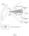
- FIG. 1illustrates a localizing system using marker tags and asset tags.
- the localizing systemcomprises a reader 110 and a location module 170.
- the reader 110may generate a transmitted electromagnetic signal represented by beam 150.
- Field of view (FOV) 160may represent the field of view for reception of the modulated backscatter signals received from marker tags 120 and/or asset tags 140.
- FOV 160is shown in two-dimensions in FIG. 1 for simplicity, and may be a three-dimensional field of view.
- a zone 130may be a region between marker tag 120A and marker tag 120B, as shown for simplicity in two dimensions in FIG. 1 .
- asset tag 140Bfalls within zone 130.
- the zone 130may also be a three dimensional region (not shown).
- one or more marker tags 120may be used to define zones having two-dimensional and/or three-dimensional geometries.
- the reader 110includes one or more antennas (not shown) for transmitting electromagnetic signals to the marker tags 120 and the asset tag 140, and one or more antennas for receiving the modulated backscatter signals from the marker tags 120 and the asset tag 140.
- the reader 110may operate in one or more of the following modes: (i) single antenna transmission, multi-antenna reception; (ii) multi-antenna transmission, multi-antenna reception; and/or (iii) multi-antenna transmission, single antenna reception.
- the marker tags 120 and asset tags 140communicate with the reader 110 using modulated backscatter signals.
- Reader 110receives modulated backscatter signals from the marker tags 120 and the asset tag 140, and estimates parameters of the modulated backscatter signals.
- an estimated parameter of a modulated backscatter signal received from a marker tag 120 and/or an asset tag 140includes any measurable quantity, characteristic, or information determined and/or estimated from the modulated backscatter signal.
- An estimated parametermay include, but is not limited to, an RFID preamble, an RFID payload data and/or additional information, a signal strength of the modulated backscatter signal received from a marker tag 120 and/or an asset tag 140, an angle of arrival of the modulated backscatter signal received from a marker tag 120 and/or an asset tag 140, an antenna array response for a modulated backscatter signal received from a marker tag 120 and/or an asset tag 140, a range from a marker tag 120 and/or an asset tag 140 to the reader 110, a time of flight of the modulated backscatter signal from the marker tag 120 and/or asset tag 140 to the reader 110.
- the location module 170may determine a direction of motion of an asset tag 140 and/or a velocity of an asset tag 140.
- the location of the marker tag 120may be stored in a database (not shown) that is accessible to the location module 170.
- the location of the marker tag 120may include an absolute or relative location in two-dimensional (x,y) coordinate space, or an absolute or relative location in three-dimensional (x,y,z) coordinate space.
- the location module 170may provide a location estimate 180 of the asset tag 140 by having reader 110 read (e.g., receive modulated backscatter signals) from one or more of the marker tags 120 and the asset tag 140 in the FOV 160 of reader 110.
- the location estimate 180may be an absolute or a relative location estimate of the asset tag 140, may provide a determination that asset tag 140 is included in the zone 130, may provide a probabilistic estimate of the absolute or relative location of asset tag 140, and/or may provide a probabilistic estimate whether the asset tag 140 is included in the zone 130.
- the location module 170may compare the location of asset tag 140B to the location of the marker tags 120A and 120B and provide the location estimate 180 including the determination that the zone 130 includes the asset tag 140B.
- the location module 170may provide the location estimate 180 at multiple time instances and/or over multiple time periods.
- the location estimate 180may be used to determine a direction of motion of the asset tag 140. This enables, for example, a reader 110 located at a doorway to determine whether an asset tag 140 may be entering or exiting a particular region of interest.
- marker tags 120 and/or asset tags 140may be passive, semi-passive, active, or combinations of these kinds of tags.
- some marker tags 120may be semi-passive in order to provide a high spatial-resolution identification of zones, while asset tags 140 may be passive tags in order to reduce cost. If a range between reader 110 and the marker tags 120 and asset tags 140 is larger than suitable for passive tags, then both marker tags 120 and asset tags 140 may be semi-passive.
- an asset tag 140can play the role of a marker tag 120, thus reducing the density of marker tags 120.
- An asset tag 140 used in this mannermay be referred to as a simulated marker tag.
- a zonemay thus be determined based on one or more simulated marker tags.
- FIG. 2illustrates a localizing system in a shelf application.
- the marker tag 120Amay be positioned at one shelf end of shelf 210, and the marker tag 120B at the other end of shelf 210.
- a zone 220may then be defined as the region on the shelf between the two marker tags 120A and 120B.
- the location module 170may provide the location estimate 180 that includes whether the asset tag 140 is in the zone 220.
- FIG. 3illustrates a localizing system in a dock door application.
- a zone including dock door 310may be defined by a radius from a marker tag 120A
- another zone including dock door 320may be defined by a radius from a marker tag 120B.
- FIG. 3illustrates a dock door application including two dock doors (dock door 310 and dock door 320)
- the localizing systemmay be used with a single dock door (not shown), or more than two dock doors (not shown).
- the reader 110may receive modulated backscatter signals from an asset tag 140 that is passing through dock door 310. Determining that the asset tag 140 is passing through dock door 310 may be based on a location estimate 180 that is within a radius from marker tag 120A.
- FIG. 4is a block diagram of an exemplary transmitter beamforming system.
- the transmitter beamforming systemcomprises phase locked loops (PLL) 410, phase shifters 420, modulators 430, antennas 440, clock 450, transmit beamforming module 460, transmit data 470 and marker tag feedback 480.
- Each of the antennas 440may be an individual antenna, or an antenna element.
- Transmitter beamforminguses two or more antennas 440 to direct the transmitted beam to a certain region in space.
- reader 110FIG. 1
- transmitter beamforming capabilitywhich enables reader 110 to select where to direct the energy of its beam 150.
- u tu 1 t , ... , u N t T
- ww 1 , ... , w N T
- u tw s t .
- the channel gain from the i th transmit element to the marker tag 120 and/or asset tag 140 in such a systemcan be modeled as a complex scalar h i .
- the modulated backscattered signal from the marker tag 120 and/or asset tag 140therefore has power proportional to (h T w) 2 .
- the strength of the modulated backscatter signal from the marker tag 120 and/or asset tag 140is related to the location of the marker tag 120 and/or asset tag 140 relative to the reader 110.
- the location module 170may provide the location estimate 180 from the modulated backscatter signals as follows.
- a main lobe of the transmit beam, such as beam 150,may be scanned through a region.
- the beam 150is electronically steered using an array of antennas 440 by controlling the relative phases and amplitudes of the radio frequency (RF) signals transmitted from the antennas 440.
- the strength of the received modulated backscatter signal from the marker tags 120 as a function of the scan anglemay be provided to marker tag feedback 280 and to the localization module 170. Using this information the location estimate 180 including the angle of arrival of the modulated backscatter signals received from the marker tags 120 can be estimated.
- the peak in the modulated backscatter signal strength as a function of the scan anglecan be used to estimate parameters of the received modulated backscatter signal including the angle of arrival.
- h ( x )is the channel vector from the reader 110 to a marker tag 120 and/or an asset tag 140 at location x relative to the reader 110.
- xmay denote a three-dimensional position, a two-dimensional position, or an angle of arrival and/or departure relative to the transmit beamforming array of reader 110.
- Q ⁇a ⁇ H a ⁇ 1 2 , ... , a ⁇ H a ⁇ K 2 .
- This techniquegeneralizes to two-dimensional arrays, which enables the estimation of two angles. While angle estimation may be based on comparing the shape of P with Q ( ⁇ ), the strength of P (the received signal strength) can be used to estimate the range of the marker tag 120 and/or the asset tag 140 relative to the reader 110. Thus, a two-dimensional transmit beamforming array can be used to estimate the three-dimensional location of a marker tag 120 and/or an asset tag 140 relative to the reader 110, by combining estimates of two angles and a range.
- the marker tag 120transmits a modulated backscatter signal including a known data sequence
- a correlation against the sequencecan be used to provide an estimate of the parameters of the received modulated backscatter signal.
- the modulated backscatter signal from a marker tag 120 and/or an asset tag 140is also known as an uplink.
- the correlationcan provide an estimate of the complex baseband channel gain, which is proportional to h T w , and can be used for adaptation of the transmit beamforming coefficients w. For example, let sample y[l] correspond to the l th symbol, b[l], transmitted on the uplink.
- This techniqueis an implicit feedback mechanism, since the reader 110 is extracting information about, and possibly adapting, the downlink based on information extracted from the uplink signal.
- the data demodulation on the uplinkis reliable enough, then this can be used for decision-directed parameter estimation by reader 110 to reduce the requirement for marker tag 120 to send a known segment of data.
- the symbols b [ l ]can be replaced by their estimates in such a decision-directed adaptation.
- the reader 110could also estimate the average received power on the uplink by, for example, computing an average of
- the parameter being estimatedmay include explicit feedback sent by the marker tag 120 to the reader 110.
- An example of explicit feedbackis when the marker tag 120 encodes specific information regarding its received signal in the data that it is sending back in the modulated backscatter signal.
- the reader 110may also use transmitter beamforming to reduce interference between conventional RFID systems and/or other transmitter beamforming systems that may be in the same area.
- the reader 110may use transmitter beamforming to direct the transmitted RF energy, such as beam 150, to desired areas and away from undesired areas using marker tag feedback 280 to control transmit beamforming module 260.
- the feedback from the marker tag 120can be implicit or explicit, as discussed herein.
- transmitter beamforming and/or power control as described hereincan reduce interference and thus accommodate multiple RFID systems and/or multiple readers 110 in close proximity.
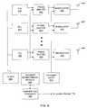
- FIG. 5is a block diagram of an exemplary receiver beamforming system.
- the receiver beamforming systemcomprises phase locked loops (PLL) 510, baseband phase shifters 520, demodulators 530, antennas 540, clock 550, receive beamforming module 560 and receive data 570.
- Each of the antennas 540may be an individual antenna, or an antenna element.
- Receiver beamformingmay use two or more antennas 540 to tune the sensitivity of the reader 110 to a region in space, such as FOV 160.
- the antennas 540may be the same as the antennas 440 described with reference to FIG. 4 .
- reader 110includes receive beamforming capability which enables reader 110 to determine localization information including an angle of arrival of the modulated backscatter signals received from the marker tags 120 and the asset tag 140.
- Reader 110may include receive beamforming implemented in baseband, as shown in FIG. 5 .
- receive beamformingimplemented in baseband, as shown in FIG. 5 .
- localizing asset tags 140is based on the relationship between the modulated backscatter signals received at the antennas 540 from the one or more marker tags 120 and the asset tag 140.
- the receive beamforming module 360can estimate the receive array response corresponding to the modulated backscatter signal from a marker tag 120 and/or an asset tag 140 by correlating the received signals at the antennas 540 against known or estimated data signals.
- the vector hmay be called the receive array response, or the spatial channel from the marker tag 120 and/or asset tag 140 to the reader 110.
- y lh b l + n l
- b[l]may denote the l th symbol transmitted on the uplink.
- a receiver beamforming systemmay form a spatial correlation of the vector received signal with complex-valued receive beamforming coefficients.
- w( w 1 ,..., w M ) T denote a vector of complex-valued beamforming coefficients, or beamforming weights.
- receive beamformingmay be implemented in the RF band using a phase adjustment of the modulated backscatter signals received by individual elements of antennas 540, according to beamforming techniques known in the art.
- the beamforming coefficients wmay be adapted by the receive beamforming module in order to track a desired signal of interest, which might, for example, be known symbols sent on the uplink by the tag.
- the values of the adapted weightsprovide information regarding the receive array response h.
- the receive beamforming modulemay estimate the receive array response h directly from y ( t ), for example, by correlating it against a set of known or estimated symbols.
- the receive array response corresponding to the marker tag 120 and/or asset tag 140can then be used by the location module 170 to provide the location estimate 180 for asset tag 140, according to techniques known in the art.
- the location module 170may also use second order statistics, such as the spatial covariance matrix C .
- the data modulated by a conventional RFID tagincludes a known preamble, followed by a payload that may include a tag identity and/or additional information.
- the marker tag 120 and/or the asset tag 140may use a known preamble to estimate the receive array response.
- a larger training sequence that improves the estimation of the receive array responsecan be provided by explicitly configuring the payload to contain additional information including a known data segment.
- the receive array response hmay be estimated using the correlation ⁇ l b * l y l , where the sequence of symbols b[l] is known a priori due to being part of a known preamble or training sequence, as discussed herein.
- the receive beamforming module 560may combine the signals received from antennas 540 using a combination of training and decision-directed adaptation according to techniques known in the art.
- the receive beamforming module 560may include adaptive algorithms known in the art based on the linear minimum mean squared error (MMSE) criterion.
- MMSElinear minimum mean squared error
- the receive beamforming coefficients wmay be adapted to minimize the mean squared error E[
- LMSleast mean squares
- RLSrecursive least squares
- BLSblock least squares
- reader 110may perform data demodulation without using a receiver beamforming system such as illustrated in FIG. 5 .
- demodulationcan be accomplished separately for each antenna (not shown) in an antenna array.
- Data demodulationcan be performed first using one or more antennas, and then the decisions can be correlated against the received signals at the different antenna elements to estimate the receive array response.
- a decision-directed estimation of hmay estimate the receive array response h using the correlation ⁇ l b * l y l , where the estimates of the symbols b[l] are obtained from demodulators.
- the receiver array response hmay be estimated by various methods including direct estimation by correlation of the vector received modulated backscatter signal against known or estimated signals, and indirect estimation by adapting receive beamforming weights w. Estimates of the receive array response may be used by the location module 170 to provide the location estimate 180 for the marker tag 120 and/or asset tag 140, relative to the reader 110, since the receive array response h depends on the location of the marker tag 120 and/or asset tag 140 relative to the antennas 540 in the receive antenna array.
- the direction in which the marker tag 120 and/or asset tag 140 lies, relative to the current position of the antennas 540can be estimated by maximizing
- antennas 540are a two-dimensional antenna array, two angles may be estimated.
- the received signal strengthcan be used to estimate the range, which then enables three-dimensional location.
- Other techniques known in the art for estimating the rangecan also be used, such as using frequency modulated continuous wave (FMCW) waveforms.
- FMCWfrequency modulated continuous wave
- a comparison of these locationscan be used to determine the location estimate 180 of the asset tag 140 relative to the marker tags 120.
- the location module 170may compare location-related parameters such as transmit or receive beamforming coefficients, or estimates of the receive array response, in order to provide the location estimate 180 for the asset tag 140 relative to the marker tags 120.
- location estimate 180may be quantized to a zone, as described herein, instead of being an explicit estimate in a two-dimensional or three-dimensional coordinate system. As discussed with reference to FIG. 1 , FIG. 2 and FIG. 3 , a zone may be defined as a region around one or more marker tags 120, without requiring that the absolute coordinates of the marker tags are known.
- the beamforming coefficients determined by receive beamforming module 560may be used for transmission by transmit beamforming module 460, thereby directing beam 150 more precisely to the region of a marker tag 120 and/or an asset tag 140.
- the transmit beamforming module 460may synthesize a null in the direction of particular marker tags 120 by adapting the transmit beamforming coefficients to be near-orthogonal to the receive beamforming coefficients.
- a reader 110 including transmitter and/or receiver beamformingmay provide improved performance by using space division multiple access (SDMA) methods known in the art.
- SDMAspace division multiple access
- reader 110can direct its transmitted energy in beam 150 to a small region, thereby reducing the number of marker tags 120 that are illuminated by beam 150.
- the use of SDMAmay simplify the task of singulation.
- multiuser detection techniques and algorithmssuch as MUSIC can be used to successfully decode simultaneous responses from multiple marker tags 120 based on the differences in their receive array responses.
- the marker tag 120 payloadincludes data encoded in a direct sequence spread spectrum format
- multiple tagsmay be read at the same time by employing code division multiple access (CDMA) techniques known in the art to successfully decode multiple responses by received by reader 110.
- CDMAcode division multiple access
- a reader 110 with receiver beamforming capabilitiessuch CDMA techniques can be used in conjunction with SDMA.
- Reader 110may also be used to determine range estimates.
- the geometry for a reader 110is analogous to radar and/or sonar since the modulated backscatter signals from marker tags 120 and asset tags 140 are electronically reflected back to reader 110. Therefore, according to methods known in the art, radar and/or sonar techniques can be used to estimate range information.
- the reader 110can transmit beam 150 including a frequency modulated continuous wave (FMCW) waveform instead of a continuous wave (CW) tone, and can process the return from the marker tag 120 and/or asset tag 140 to detect the frequency difference between the transmitted FMCW waveform and the received FMCW waveform, and thereby estimate the range as may be done in FMCW radar.
- Reader 110may be used to determine range information using the strength of a modulated backscatter signal received from a marker tag 120 and/or an asset tag 140.
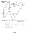
- FIG. 6illustrates a localizing system in a multipath environment.
- Reader 110 and location module 170may localize marker tags 120 and/or asset tags 140 in the presence of multipath components from reflecting or scattering objects.
- One such reflecting or scattering objectis a ground surface.
- a multipath environmentmay include reader 110 at a location (x, y, z), ground 630, a marker tag 120 at location (x t , y t , z t ).
- the reader 110receives direct backscatter 610 from marker tag 120, and ground reflection 620.
- a maximum likelihood (ML) estimate of the location of the marker tag 120 and/or the asset tag 140corresponds to maximizing the correlation of the received array response against the array manifold.
- the ML estimatedepends on the geometry.
- a dominant multipath componentmay be the ground reflection 620 reflected from ground 630.
- Other reflecting or scattering objects between the reader 110 and marker tag 120 and/or asset tag 140may also produce multipath components.
- a 1is the array response corresponding to the direct backscatter 610 (LOS path)
- a 2is the array response corresponding to path from the ground reflection 620
- ⁇ 1 , ⁇ 2are complex gains corresponding to these paths and depend on the propagation environment, and may be unknown
- Nis noise.
- the receive array response h abovemay denote an estimate of the receive array response, obtained using one of the techniques discussed herein, and the noise N may be interpreted as estimation noise, which is typically well approximated as white and Gaussian.
- One approach to modeling these complex gainsis to obtain a joint ML estimate of the complex gains and the location of marker tag 120, ( x 1 , y 1 , z 1 ), by performing the minimization:
- One solution known in the artis to choose a location of marker tag 120 ( x t , y t , z t ) that minimizes the projection of y orthogonal to the subspace spanned by a 1 ( x t , y t , z t ) and a 2 ( x t , y t , z t ).
- the search for the best estimate of the location ( x t , y t , z t )can be constrained further based on additional information (e.g., range estimates, or prior knowledge of the distance of the reader 110 from the location estimate of the marker tag 120.)
- the dependence of the receive array response for the location of marker tag 120may not be correctly modeled as described herein. However, the received array response still varies smoothly with the location of marker tag 120. Thus, if one or more marker tags 120 are placed densely enough, then a comparison of the array response for an asset tag 140 ( FIG. 1 ) with those of marker tags 120 (e.g., by computing the normalized correlation between the estimated parameters) can be used to estimate the location of the asset tag 140. If h a and h b are the estimated receive array responses for tags a and b, then the normalized correlation may be defined as: h a H h b h a H h a h a H h b .
- the received array responseis highly correlated with those for the marker tags 120 on a shelf 210 ( FIG. 2 ), as determined by a clustering algorithm, then one would estimate that the asset tag 140 is on the shelf 210.
- FIG. 7illustrates a localizing system in a two-dimensional mobile reader configuration.
- the reader 701may be mobile, i.e., the reader 701 may be moved from a first position to a second position (indicated as reader 702).
- a mobile reader configurationmay used to take an inventory of asset tags 140 over an entire store.
- reader 110may receive modulated backscatter signals from a plurality of marker tags 120 and an asset tag 140 using a reader 701, where reader 701 is an embodiment of reader 110 at the first position. Then, the reader 702 may receive modulated backscatter signals from the plurality of marker tags 120 and the asset tag 140, where reader 702 is an embodiment of reader 110 at the second position.
- an angle 710may be defined as an angle between the marker tag 120A and an axis of reader 701.
- an angle 720may be defined between the asset tag 140 and the axis of reader 701
- an angle 730may be defined as an angle between the marker tag 120B and the axis of reader 501.
- Range 715is defined as the distance between the marker tag 120A and the reader 701.
- range 725is defined as the distance between the asset tag 140 and the reader 701
- range 735is defined as the distance between the marker tag 120B and the reader 701.
- angles 740 and 760may be defined from the marker tags 120A and 120B, respectively, and the axis of reader 702.
- Angle 750may be defined from the asset tag 140 and the axis of reader 702.
- ranges 745 and 765may be defined from the marker tags 120A and 120B, respectively, and the reader 702.
- Range 755may be defined as the distance from asset tag 140 and reader 702.
- estimated parameters of the modulated backscatter signals received from marker tags 120A and 120Binclude the angles 710 and 730 (with respect to the axis of reader 701), and angles 740 and 760 (with respect to the axis of reader 702).
- the estimated parameters of the modulated backscatter signals received from the asset tag 140include the angles 720 and 750.
- the location module 170may provide the location estimate 180 for the asset tag 140 using the locations of marker tags 120A and 120B, the angles 710, 720, 730, 740, 750, 760, and geometry, by first estimating the locations of the reader 701 and the reader 702.
- the location of the reader 701can be estimated using the locations of the marker tags 120A and 120B, the angles 710 and 730, and simple geometric calculations.
- the location of the reader 702can likewise be estimated.
- the location module 170may estimate the location of the reader 702 using the locations of the marker tags 120A and 120B, the angles 740 and 760, and similar geometric calculations.
- the location of the asset tag 140may be estimated using the estimates of the locations of the readers 701 and 702, the angles 720 and 750, and similar geometric calculations.
- FIG. 7is shown in two dimensions for simplicity, the location of the asset tag 140, reader 701 and reader 702 may also be estimated in three dimensions using similar geometrical calculations generalized to three-dimensions.
- estimated parameters of the modulated backscatter signals received from marker tags 120A and 120Binclude the ranges 715 and 735 (to reader 701) and ranges 745 and 765 (to reader 702).
- the estimated parameters of the modulated backscatter signals received from the asset tag 140include the ranges 725 and 755.
- the location module 170may provide the location estimate 180 for the asset tag 140 using, for example, the locations of marker tags 120A and 120B, the ranges 715, 725, 735, 745, 755, 765, and geometry.
- the location of the asset tag 140may be estimated.
- the location of the reader 701can be estimated using the locations of the marker tags 120A and 120B, the ranges 715 and 735, and geometric calculations.
- the location of the reader 701may be likewise estimated.
- the solution that corresponds to the location of the reader 701can be determined based on, for example, by knowing which side of the marker tags 120A and 120B the reader 110 is on.
- the location modulemay estimate the location of the reader 702 using the locations of the marker tags 120A and 120B, the ranges 745 and 765, and similar geometric calculations. Subsequently, the location estimate 180 of the asset tag 140 may be estimated using the estimates of the locations of the readers 701 and 702, the ranges 725 and 755, and similar geometric calculations. The location of the asset tag 140, reader 701 and 702 may also be estimated in three dimensions using geometry.
- the estimated parameters of the modulated backscatter signals received from marker tags 120 and/or asset tag 140are received array responses.
- location module 170may provide the location estimate 180 for the marker tags 120 and/or asset tag 140 using the received array responses and may use prior knowledge of, or models of, the multipath environment. For example, if the multipath environment consists primarily of a line-of-sight path and a ground reflection, as illustrated in FIG. 6 , then a ML or Bayesian approach may be used for estimating the locations of the reader 110 (e.g., reader 701 and reader 702), marker tags 120 and asset tag 140 by taking into account the complex gains associated with each path.
- the reader 110e.g., reader 701 and reader 702
Landscapes
- Engineering & Computer Science (AREA)
- Radar, Positioning & Navigation (AREA)
- Remote Sensing (AREA)
- Physics & Mathematics (AREA)
- General Physics & Mathematics (AREA)
- Computer Networks & Wireless Communication (AREA)
- Radar Systems Or Details Thereof (AREA)
- Burglar Alarm Systems (AREA)
- Radio Transmission System (AREA)
Description
- The present invention relates generally to asset tracking, and more particularly to localizing tagged assets using modulated backscatter.
- In a conventional radio frequency identification (RFID) system, data encoded in a tag is communicated by the tag to a reader in response to a query from the reader. A tag may be batteryless (i.e., a passive tag), in which case a transmitted beam from the reader energizes the tag's circuitry, and the tag then communicates data encoded in the tag to the reader using modulated backscatter. Since the tag is typically affixed to an asset (e.g., an item being tracked by the RFID system), the data encoded in the tag may be used to uniquely identify the asset.
- In the case of a semi-passive tag, a battery included with the tag powers the tag's circuitry. When the tag detects the transmitted beam from the reader, the tag communicates data encoded in the tag to the reader using modulated backscatter. In the case of an active tag, a battery included with the tag may power the communication to the reader without first detecting or being energized by the transmit beam. Semi-passive tags and active tags may also include data encoded in the tag that may uniquely identify the asset.
- In conventional RFID systems, the ability of the reader to determine the location of a tag may be limited because the reader typically transmits a beam with a broad pattern. Conventional RFID systems may employ a reader including one or more antennas, where each antenna has a fixed beam pattern. These antennas are typically separated by a spacing that is large compared to the transmitted beam's wavelength, in order to provide diversity against multi-path fading and to increase the reliability of receiving the communication from tags with unknown orientations. In addition, conventional RFID systems may be limited when the communication range between a single fixed reader and a tag is too small to read all tags in an area of interest.
US-A-6 046 683 discloses a system and method according to the preamble of the independent claims, wherein this conventional system is reliant on the use of Doppler shift to determine tag location.US-A-6 600 418 discloses a method and system which simply uses proximity of the interrogator and tag to determine the tag's location.US 2008/030422 A1 discloses a multi-protocol, multi-band array antenna system, which is used in an RFID system reader and sensory network. The system is adapted for employing a digital beam forming technique for transmission a steering of a beam to a specific sensor tag for a group of tags in a cell.US 2007/285245 A1 discloses an RFID system and methods for tracking and locating an RFID tag, including a reader, an identification tag, sensor-tags and a data processing element. The sensor-tags determine whether the identification tag is within a predetermined sensor-tag range and communicate a response signal to the reader when a request signal is received from the reader. Based on responses of the sensor-tags, the location of the object with the responding RFID tag can be calculated.- Therefore, it is an objective of the invention to provide an improved system and method for localizing tagged assets using modulated backscatter.
- Embodiments of the invention include a method and system for receiving modulated backscatter signals using a reader from one or more marker tags in accordance with
claims 1 and 18. - Elements in the figures are illustrated for simplicity and clarity and are not drawn to scale. The dimensions of some of the elements may be exaggerated relative to other elements to help improve the understanding of various embodiments of the invention.
FIG. 1 illustrates a localizing system using marker tags and asset tags.FIG. 2 illustrates a localizing system in a shelf application.FIG. 3 illustrates a localizing system in a dock door application.FIG. 4 is a block diagram of an exemplary transmitter beamforming system.FIG. 5 is a block diagram of an exemplary receiver beamforming system.FIG. 6 illustrates a localizing system in a multipath environment.FIG. 7 illustrates a localizing system in a two-dimensional mobile reader configuration.- The present invention includes methods and systems for localizing an asset using the modulated backscatter from an asset tag and one or more marker tags. The modulated backscattered signals from marker tags may be used by a reader and a location module to estimate location of the reader and the asset tags. An asset is any item whose location is of interest, and an asset tag is a tag associated with the asset, for example, by affixing the asset tag to the asset. Assets may be inanimate objects such as books, or persons, animals, and/or plants.
- The methods and systems enable location-enabled inventory, where the estimated locations of tagged assets are determined in an area of interest. Furthermore, in embodiments including a mobile reader, the methods and systems can localize asset tags throughout a large area and can, for example, take an inventory of tagged assets throughout the large area.
- The system includes the reader and the location module and one or more marker tags that are used to provide location estimates for the asset tag based partially on a prior knowledge of the location of each of the one or more marker tags. The location for each marker tag may be stored in a database. A location estimate for an asset tag may be determined based on the marker tags. Once the location of an asset tag is estimated, the asset tag may act as a marker tag, and is described herein as a simulated marker tag.
- A location module determines a location estimate for the asset tag using the estimated parameters of the modulated backscatter signals received from one or more marker tags and from the asset tag. The parameters may be represented by scalar or vector values, and may include, for example, the angle of arrival of the modulated backscatter signals with respect to an axis of the reader, and/or a range (i.e., distance) from the marker tag and/or the asset tag to the reader. Using the known locations of the marker tags and the estimated parameters, the location estimate of the asset tag can be determined. A location estimate may be a relative location, an absolute location, and/or a zone including the marker tags.
- In one example, a zone including an asset tag may be determined by marker tags at each end of a bookshelf. When the asset tag is affixed to an item on the bookshelf, such as a book, the book may thereby be determined to be in the zone, and likewise on the bookshelf. In this configuration, a relative location of the reader may also be determined by processing the received modulated backscatter signals from the asset tag and the marker tags.
FIG. 1 illustrates a localizing system using marker tags and asset tags. The localizing system comprises areader 110 and alocation module 170. Thereader 110 may generate a transmitted electromagnetic signal represented bybeam 150. Field of view (FOV) 160 may represent the field of view for reception of the modulated backscatter signals received frommarker tags 120 and/orasset tags 140.FOV 160 is shown in two-dimensions inFIG. 1 for simplicity, and may be a three-dimensional field of view. Azone 130 may be a region betweenmarker tag 120A andmarker tag 120B, as shown for simplicity in two dimensions inFIG. 1 . As illustrated inFIG. 1 ,asset tag 140B falls withinzone 130. In various embodiments, thezone 130 may also be a three dimensional region (not shown). Thus, one ormore marker tags 120 may be used to define zones having two-dimensional and/or three-dimensional geometries.- In various embodiments, the
reader 110 includes one or more antennas (not shown) for transmitting electromagnetic signals to themarker tags 120 and theasset tag 140, and one or more antennas for receiving the modulated backscatter signals from themarker tags 120 and theasset tag 140. Thereader 110 may operate in one or more of the following modes: (i) single antenna transmission, multi-antenna reception; (ii) multi-antenna transmission, multi-antenna reception; and/or (iii) multi-antenna transmission, single antenna reception. - The
marker tags 120 andasset tags 140 communicate with thereader 110 using modulated backscatter signals. Reader 110 receives modulated backscatter signals from themarker tags 120 and theasset tag 140, and estimates parameters of the modulated backscatter signals. As used herein, an estimated parameter of a modulated backscatter signal received from amarker tag 120 and/or anasset tag 140 includes any measurable quantity, characteristic, or information determined and/or estimated from the modulated backscatter signal. - An estimated parameter may include, but is not limited to, an RFID preamble, an RFID payload data and/or additional information, a signal strength of the modulated backscatter signal received from a
marker tag 120 and/or anasset tag 140, an angle of arrival of the modulated backscatter signal received from amarker tag 120 and/or anasset tag 140, an antenna array response for a modulated backscatter signal received from amarker tag 120 and/or anasset tag 140, a range from amarker tag 120 and/or anasset tag 140 to thereader 110, a time of flight of the modulated backscatter signal from themarker tag 120 and/orasset tag 140 to thereader 110. Whenreader 110 estimates the parameters of the modulated backscatter signals over time, thelocation module 170 may determine a direction of motion of anasset tag 140 and/or a velocity of anasset tag 140. - The location of the
marker tag 120 may be stored in a database (not shown) that is accessible to thelocation module 170. The location of themarker tag 120 may include an absolute or relative location in two-dimensional (x,y) coordinate space, or an absolute or relative location in three-dimensional (x,y,z) coordinate space. - The
location module 170 may provide alocation estimate 180 of theasset tag 140 by havingreader 110 read (e.g., receive modulated backscatter signals) from one or more of the marker tags 120 and theasset tag 140 in theFOV 160 ofreader 110. Thelocation estimate 180 may be an absolute or a relative location estimate of theasset tag 140, may provide a determination thatasset tag 140 is included in thezone 130, may provide a probabilistic estimate of the absolute or relative location ofasset tag 140, and/or may provide a probabilistic estimate whether theasset tag 140 is included in thezone 130. For example, when thereader 110 readsasset tag 140B, thelocation module 170 may compare the location ofasset tag 140B to the location of themarker tags location estimate 180 including the determination that thezone 130 includes theasset tag 140B. - In various embodiments, the
location module 170 may provide thelocation estimate 180 at multiple time instances and/or over multiple time periods. Thus, thelocation estimate 180 may be used to determine a direction of motion of theasset tag 140. This enables, for example, areader 110 located at a doorway to determine whether anasset tag 140 may be entering or exiting a particular region of interest. - In various embodiments, marker tags 120 and/or
asset tags 140 may be passive, semi-passive, active, or combinations of these kinds of tags. For example, somemarker tags 120 may be semi-passive in order to provide a high spatial-resolution identification of zones, whileasset tags 140 may be passive tags in order to reduce cost. If a range betweenreader 110 and the marker tags 120 andasset tags 140 is larger than suitable for passive tags, then bothmarker tags 120 andasset tags 140 may be semi-passive. - Once the location of an
asset tag 140 has been estimated, theasset tag 140 can play the role of amarker tag 120, thus reducing the density of marker tags 120. Anasset tag 140 used in this manner may be referred to as a simulated marker tag. A zone may thus be determined based on one or more simulated marker tags. FIG. 2 illustrates a localizing system in a shelf application. Themarker tag 120A may be positioned at one shelf end ofshelf 210, and themarker tag 120B at the other end ofshelf 210. Azone 220 may then be defined as the region on the shelf between the twomarker tags location module 170 may provide thelocation estimate 180 that includes whether theasset tag 140 is in thezone 220.FIG. 3 illustrates a localizing system in a dock door application. In this application, a zone includingdock door 310 may be defined by a radius from amarker tag 120A, and another zone includingdock door 320 may be defined by a radius from amarker tag 120B. AlthoughFIG. 3 illustrates a dock door application including two dock doors (dock door 310 and dock door 320), the localizing system may be used with a single dock door (not shown), or more than two dock doors (not shown).- The
reader 110 may receive modulated backscatter signals from anasset tag 140 that is passing throughdock door 310. Determining that theasset tag 140 is passing throughdock door 310 may be based on alocation estimate 180 that is within a radius frommarker tag 120A. FIG. 4 is a block diagram of an exemplary transmitter beamforming system. The transmitter beamforming system comprises phase locked loops (PLL) 410,phase shifters 420,modulators 430,antennas 440,clock 450, transmitbeamforming module 460, transmitdata 470 andmarker tag feedback 480. Each of theantennas 440 may be an individual antenna, or an antenna element. Transmitter beamforming uses two ormore antennas 440 to direct the transmitted beam to a certain region in space. In various embodiments, reader 110 (FIG. 1 ) includes transmitter beamforming capability which enablesreader 110 to select where to direct the energy of itsbeam 150.- In terms of the standard complex baseband representation for passband signals, if the transmitter beamforming system has N antenna elements, then the transmitted signalu¡(t) from theith antenna,i=1, ...,N, is given bywi s(t), wherewi is a complex gain termed theith beamforming coefficient, ands(t) is the signal (in general, complex-valued) to be transmitted. In a vector format,


- If the signals(t) is narrowband (i.e., its bandwidth is small relative to the coherence bandwidth of the channel), then the channel gain from theith transmit element to the
marker tag 120 and/orasset tag 140 in such a system can be modeled as a complex scalarhi. Defining the channel vector
marker tag 120 and/orasset tag 140 can be modeled as:
- The modulated backscattered signal from the
marker tag 120 and/orasset tag 140 therefore has power proportional to(hTw)2. The channel vectorh depends on the location of themarker tag 120 and/orasset tag 140 relative to theantennas 440. For example, whenantennas 440 are linear array with elements spaced byd, the channel vector for amarker tag 120 and/orasset tag 140 lying at an angle θ relative to the broadside is given by:

marker tag 120 and/orasset tag 140 is related to the location of themarker tag 120 and/orasset tag 140 relative to thereader 110. - Using transmitter beamforming, the
location module 170 may provide thelocation estimate 180 from the modulated backscatter signals as follows. A main lobe of the transmit beam, such asbeam 150, may be scanned through a region. Thebeam 150 is electronically steered using an array ofantennas 440 by controlling the relative phases and amplitudes of the radio frequency (RF) signals transmitted from theantennas 440. The strength of the received modulated backscatter signal from the marker tags 120 as a function of the scan angle may be provided to marker tag feedback 280 and to thelocalization module 170. Using this information thelocation estimate 180 including the angle of arrival of the modulated backscatter signals received from the marker tags 120 can be estimated. - The peak in the modulated backscatter signal strength as a function of the scan angle, for example, can be used to estimate parameters of the received modulated backscatter signal including the angle of arrival. For a high spatial-resolution estimate, suppose thatwk is the vector of transmit beamforming coefficients corresponding to thekth scan, wherek=1, ...,K, and thath(x) is the channel vector from the
reader 110 to amarker tag 120 and/or anasset tag 140 at locationx relative to thereader 110. Herex may denote a three-dimensional position, a two-dimensional position, or an angle of arrival and/or departure relative to the transmit beamforming array ofreader 110. The vector of received powers over theK scans is then proportional to:
- A comparison of the actual vector of received powersP = (PI...,PK) withQ(x) can therefore be used to estimatex from among a set of feasible values forx. For example, consider an array with array responsea(θ). In order to form a beam towards angle θk on thekth scan, the beamforming coefficients are set towk =a* (θk), so that the peak of (hTwk)2 occurs ath =a(θk). The vector of expected receive powers from the
marker tag 120 and/or theasset tag 140 at angle θ is therefore given by:
- This technique generalizes to two-dimensional arrays, which enables the estimation of two angles. While angle estimation may be based on comparing the shape ofP withQ(θ), the strength ofP (the received signal strength) can be used to estimate the range of the
marker tag 120 and/or theasset tag 140 relative to thereader 110. Thus, a two-dimensional transmit beamforming array can be used to estimate the three-dimensional location of amarker tag 120 and/or anasset tag 140 relative to thereader 110, by combining estimates of two angles and a range. - If the
marker tag 120 transmits a modulated backscatter signal including a known data sequence, then a correlation against the sequence can be used to provide an estimate of the parameters of the received modulated backscatter signal. The modulated backscatter signal from amarker tag 120 and/or anasset tag 140 is also known as an uplink. The correlation can provide an estimate of the complex baseband channel gain, which is proportional tohTw, and can be used for adaptation of the transmit beamforming coefficientsw. For example, let sampley[l] correspond to thelth symbol,b[l], transmitted on the uplink. Then:
marker tag 120 and/or theasset tag 140 and the propagation toreader 110. Then, the correlation
- This technique is an implicit feedback mechanism, since the
reader 110 is extracting information about, and possibly adapting, the downlink based on information extracted from the uplink signal. Alternatively, if the data demodulation on the uplink is reliable enough, then this can be used for decision-directed parameter estimation byreader 110 to reduce the requirement formarker tag 120 to send a known segment of data. Thus, the symbolsb[l] can be replaced by their estimates in such a decision-directed adaptation. Thereader 110 could also estimate the average received power on the uplink by, for example, computing an average of |y[l]|2. The parameter being estimated may include explicit feedback sent by themarker tag 120 to thereader 110. An example of explicit feedback is when themarker tag 120 encodes specific information regarding its received signal in the data that it is sending back in the modulated backscatter signal. - The
reader 110 may also use transmitter beamforming to reduce interference between conventional RFID systems and/or other transmitter beamforming systems that may be in the same area. Using the marker tags 120, thereader 110 may use transmitter beamforming to direct the transmitted RF energy, such asbeam 150, to desired areas and away from undesired areas using marker tag feedback 280 to control transmit beamforming module 260. The feedback from themarker tag 120 can be implicit or explicit, as discussed herein. Thus, transmitter beamforming and/or power control as described herein can reduce interference and thus accommodate multiple RFID systems and/ormultiple readers 110 in close proximity. FIG. 5 is a block diagram of an exemplary receiver beamforming system. The receiver beamforming system comprises phase locked loops (PLL) 510,baseband phase shifters 520,demodulators 530,antennas 540,clock 550, receivebeamforming module 560 and receivedata 570. Each of theantennas 540 may be an individual antenna, or an antenna element. Receiver beamforming may use two ormore antennas 540 to tune the sensitivity of thereader 110 to a region in space, such asFOV 160. In various embodiments, theantennas 540 may be the same as theantennas 440 described with reference toFIG. 4 . In various embodiments,reader 110 includes receive beamforming capability which enablesreader 110 to determine localization information including an angle of arrival of the modulated backscatter signals received from the marker tags 120 and theasset tag 140.Reader 110 may include receive beamforming implemented in baseband, as shown inFIG. 5 . Using receiver beamforming, localizingasset tags 140 is based on the relationship between the modulated backscatter signals received at theantennas 540 from the one ormore marker tags 120 and theasset tag 140. The receive beamforming module 360 can estimate the receive array response corresponding to the modulated backscatter signal from amarker tag 120 and/or anasset tag 140 by correlating the received signals at theantennas 540 against known or estimated data signals.- For example, consider narrowband signaling (in which the signal bandwidth is smaller than the channel coherence bandwidth) and a
reader 110 withM antennas. Using the complex baseband representation for the passband received signals at theM antennas, the received signal for thejth antenna, wherej=1, ...,M, can be written asyj(t) =hjv(t) +nj(t), wherev(t) is the signal backscattered by the tag,hj is the complex channel gain from the tag to thejth antenna element, andnj(t) is the noise seen by thejth antenna element. Using the vector notation:


marker tag 120 and/orasset tag 140 to thereader 110. - It is also useful to consider a discrete-time mode of the preceding representation (possibly obtained by filtering and sampling the continuous-time vector signal y(t)), as follows:


- For the discrete-time model, the corresponding inner product may follow the model:

FIG. 5 , as well as amplitude scaling (not shown). - In various embodiments, receive beamforming may be implemented in the RF band using a phase adjustment of the modulated backscatter signals received by individual elements of
antennas 540, according to beamforming techniques known in the art. The beamforming coefficientsw may be adapted by the receive beamforming module in order to track a desired signal of interest, which might, for example, be known symbols sent on the uplink by the tag. The values of the adapted weights provide information regarding the receive array responseh. Alternatively, the receive beamforming module may estimate the receive array responseh directly fromy(t), for example, by correlating it against a set of known or estimated symbols. Another quantity of interest is the spatial covariance matrixC:
- The receive array response corresponding to the
marker tag 120 and/orasset tag 140 can then be used by thelocation module 170 to provide thelocation estimate 180 forasset tag 140, according to techniques known in the art. Thelocation module 170 may also use second order statistics, such as the spatial covariance matrixC. In typical RFID protocols, the data modulated by a conventional RFID tag includes a known preamble, followed by a payload that may include a tag identity and/or additional information. In various embodiments, themarker tag 120 and/or theasset tag 140 may use a known preamble to estimate the receive array response. In addition to the preamble provided by the RFID protocol, a larger training sequence that improves the estimation of the receive array response can be provided by explicitly configuring the payload to contain additional information including a known data segment. For example, for the discrete-time model:

- The receive
beamforming module 560 may combine the signals received fromantennas 540 using a combination of training and decision-directed adaptation according to techniques known in the art. For example, the receivebeamforming module 560 may include adaptive algorithms known in the art based on the linear minimum mean squared error (MMSE) criterion. For example, for the discrete-time model:
marker tag 120 and/orasset tag 140 is communicating with the reader, and the noise is white, then the MMSE beamforming coefficients are a scalar multiple ofh. Thus, adaptation ofw provides information about the receive array responseh. The beamforming coefficientsw thus determined may be provided to thelocation module 170. The location module can also be provided with additional information such as the spatial covariance matrixC. - In various embodiments,
reader 110 may perform data demodulation without using a receiver beamforming system such as illustrated inFIG. 5 . In these embodiments, demodulation can be accomplished separately for each antenna (not shown) in an antenna array. Data demodulation can be performed first using one or more antennas, and then the decisions can be correlated against the received signals at the different antenna elements to estimate the receive array response. For example, for the discrete-time model:

- As described herein, the receiver array responseh may be estimated by various methods including direct estimation by correlation of the vector received modulated backscatter signal against known or estimated signals, and indirect estimation by adapting receive beamforming weightsw. Estimates of the receive array response may be used by the
location module 170 to provide thelocation estimate 180 for themarker tag 120 and/orasset tag 140, relative to thereader 110, since the receive array responseh depends on the location of themarker tag 120 and/orasset tag 140 relative to theantennas 540 in the receive antenna array. - For example, when
antennas 540 are a linear array with elements spaced byd, the channel vector for amarker tag 120 and/orasset tag 140 at an angle θ relative to the broadside is given by:

antennas 540 and themarker tag 120 and/orasset tag 140, the direction in which themarker tag 120 and/orasset tag 140 lies, relative to the current position of theantennas 540, can be estimated by maximizing |aH(θ)h| as a function of θ over its permissible range. For an embodiment whereantennas 540 are a two-dimensional antenna array, two angles may be estimated. Furthermore, the received signal strength can be used to estimate the range, which then enables three-dimensional location. Other techniques known in the art for estimating the range can also be used, such as using frequency modulated continuous wave (FMCW) waveforms. - Once the location of the marker tags 120 and/or
asset tag 140 relative to thereader 110 have been determined by thelocation module 170, a comparison of these locations can be used to determine thelocation estimate 180 of theasset tag 140 relative to the marker tags 120. Thus, if the absolute location of the marker tags 120 is known, then the absolute location of theasset tag 140 can be determined. Alternatively, thelocation module 170 may compare location-related parameters such as transmit or receive beamforming coefficients, or estimates of the receive array response, in order to provide thelocation estimate 180 for theasset tag 140 relative to the marker tags 120. Such alocation estimate 180 may be quantized to a zone, as described herein, instead of being an explicit estimate in a two-dimensional or three-dimensional coordinate system. As discussed with reference toFIG. 1 ,FIG. 2 andFIG. 3 , a zone may be defined as a region around one ormore marker tags 120, without requiring that the absolute coordinates of the marker tags are known. - If the
antennas 440 described with reference toFIG. 4 and theantennas 540 described with reference toFIG. 5 are the same antenna array, the beamforming coefficients determined by receivebeamforming module 560 may be used for transmission by transmitbeamforming module 460, thereby directingbeam 150 more precisely to the region of amarker tag 120 and/or anasset tag 140. Alternatively, to reduce interference frommarker tags 120 in a particular region, the transmitbeamforming module 460 may synthesize a null in the direction of particular marker tags 120 by adapting the transmit beamforming coefficients to be near-orthogonal to the receive beamforming coefficients. - A
reader 110 including transmitter and/or receiver beamforming may provide improved performance by using space division multiple access (SDMA) methods known in the art. For example,reader 110 can direct its transmitted energy inbeam 150 to a small region, thereby reducing the number ofmarker tags 120 that are illuminated bybeam 150. In various embodiments, the use of SDMA may simplify the task of singulation. For areader 110 including receive beamforming, multiuser detection techniques and algorithms such as MUSIC can be used to successfully decode simultaneous responses frommultiple marker tags 120 based on the differences in their receive array responses. Furthermore, if themarker tag 120 payload includes data encoded in a direct sequence spread spectrum format, then multiple tags may be read at the same time by employing code division multiple access (CDMA) techniques known in the art to successfully decode multiple responses by received byreader 110. In areader 110 with receiver beamforming capabilities, such CDMA techniques can be used in conjunction with SDMA. Reader 110 may also be used to determine range estimates. The geometry for areader 110 is analogous to radar and/or sonar since the modulated backscatter signals frommarker tags 120 andasset tags 140 are electronically reflected back toreader 110. Therefore, according to methods known in the art, radar and/or sonar techniques can be used to estimate range information. For example, thereader 110 can transmitbeam 150 including a frequency modulated continuous wave (FMCW) waveform instead of a continuous wave (CW) tone, and can process the return from themarker tag 120 and/orasset tag 140 to detect the frequency difference between the transmitted FMCW waveform and the received FMCW waveform, and thereby estimate the range as may be done in FMCW radar.Reader 110 may be used to determine range information using the strength of a modulated backscatter signal received from amarker tag 120 and/or anasset tag 140.FIG. 6 illustrates a localizing system in a multipath environment.Reader 110 andlocation module 170 may localizemarker tags 120 and/orasset tags 140 in the presence of multipath components from reflecting or scattering objects. One such reflecting or scattering object is a ground surface. As illustrated inFIG. 6 , a multipath environment may includereader 110 at a location (x, y, z),ground 630, amarker tag 120 at location (xt, yt, zt). Thereader 110 receivesdirect backscatter 610 frommarker tag 120, andground reflection 620.- In a simple line of sight (LOS) environment without a
ground reflection 620, a maximum likelihood (ML) estimate of the location of themarker tag 120 and/or theasset tag 140 corresponds to maximizing the correlation of the received array response against the array manifold. However, for a multipath environment, the ML estimate depends on the geometry. In one example, a dominant multipath component may be theground reflection 620 reflected fromground 630. Other reflecting or scattering objects between thereader 110 andmarker tag 120 and/orasset tag 140 may also produce multipath components. - The complex baseband received array response corresponding to the multipath environment illustrated in
FIG. 6 may be modeled by:
ground reflection 620, α1,α2 are complex gains corresponding to these paths and depend on the propagation environment, and may be unknown, andN is noise. The receive array responseh above may denote an estimate of the receive array response, obtained using one of the techniques discussed herein, and the noiseN may be interpreted as estimation noise, which is typically well approximated as white and Gaussian. - One approach to modeling these complex gains is to obtain a joint ML estimate of the complex gains and the location of
marker tag 120, (x1,y1,z1), by performing the minimization: - minα
1 ,α2 min(x,y1,z1 )(y-α1a1(x1,y1,z1)+α2a2(x1,y1,z1))H(y-α1a1(x1,y1,z1)+α2a2(x1,y1,z1)) whereH is the conjugate transpose and the minimization is optimal when the noise,N, is additive white Gaussian. - One solution known in the art is to choose a location of marker tag 120 (xt,yt,zt) that minimizes the projection of y orthogonal to the subspace spanned bya1(xt,yt,zt) anda2(xt,yt,zt). The search for the best estimate of the location (xt,yt,zt) can be constrained further based on additional information (e.g., range estimates, or prior knowledge of the distance of the
reader 110 from the location estimate of themarker tag 120.) - Other solutions known in the art include use of algorithms such as MUSIC or ESPRIT for finding the dominant multipath components, based on the spatial correlation matrix. In general, finding the best fit location for
marker tag 120 for a particular receive array response can be achieved using standard ML or Bayesian techniques that take into account models of the multipath environment. - For a rich scattering environment, where the multipath is not sparse enough to model as described herein, the dependence of the receive array response for the location of
marker tag 120 may not be correctly modeled as described herein. However, the received array response still varies smoothly with the location ofmarker tag 120. Thus, if one ormore marker tags 120 are placed densely enough, then a comparison of the array response for an asset tag 140 (FIG. 1 ) with those of marker tags 120 (e.g., by computing the normalized correlation between the estimated parameters) can be used to estimate the location of theasset tag 140. Ifha andhb are the estimated receive array responses for tags a and b, then the normalized correlation may be defined as:
- For example, if the received array response is highly correlated with those for the marker tags 120 on a shelf 210 (
FIG. 2 ), as determined by a clustering algorithm, then one would estimate that theasset tag 140 is on theshelf 210. FIG. 7 illustrates a localizing system in a two-dimensional mobile reader configuration. In various embodiments, thereader 701 may be mobile, i.e., thereader 701 may be moved from a first position to a second position (indicated as reader 702). A mobile reader configuration may used to take an inventory ofasset tags 140 over an entire store.- In the mobile configuration,
reader 110 may receive modulated backscatter signals from a plurality ofmarker tags 120 and anasset tag 140 using areader 701, wherereader 701 is an embodiment ofreader 110 at the first position. Then, thereader 702 may receive modulated backscatter signals from the plurality ofmarker tags 120 and theasset tag 140, wherereader 702 is an embodiment ofreader 110 at the second position. - As illustrated in
FIG. 7 , anangle 710 may be defined as an angle between themarker tag 120A and an axis ofreader 701. Likewise, anangle 720 may be defined between theasset tag 140 and the axis ofreader 701, and anangle 730 may be defined as an angle between themarker tag 120B and the axis of reader 501.Range 715 is defined as the distance between themarker tag 120A and thereader 701. Likewise,range 725 is defined as the distance between theasset tag 140 and thereader 701, andrange 735 is defined as the distance between themarker tag 120B and thereader 701. - Similarly, angles 740 and 760 may be defined from the
marker tags reader 702.Angle 750 may be defined from theasset tag 140 and the axis ofreader 702. Likewise, ranges 745 and 765 may be defined from themarker tags reader 702. Range 755 may be defined as the distance fromasset tag 140 andreader 702. - In one embodiment, estimated parameters of the modulated backscatter signals received from
marker tags angles 710 and 730 (with respect to the axis of reader 701), and angles 740 and 760 (with respect to the axis of reader 702). In this embodiment, the estimated parameters of the modulated backscatter signals received from theasset tag 140 include theangles - Since the positions of the
marker tags location module 170 may provide thelocation estimate 180 for theasset tag 140 using the locations ofmarker tags angles reader 701 and thereader 702. The location of thereader 701 can be estimated using the locations of themarker tags angles reader 702 can likewise be estimated. - The
location module 170 may provide thelocation estimate 180 for theasset tag 140 as follows: denote (x1,y1) the location ofmarker tag 120A, (x2,y2) the location ofmarker tag 120B, θ1 theangle 730, and θ2 theangle 710. Then, the location (a1,b1) ofreader 701 can be estimated by solving the following equations:
- The
location module 170 may estimate the location of thereader 702 using the locations of themarker tags angles - Subsequently, the location of the
asset tag 140 may be estimated using the estimates of the locations of thereaders angles FIG. 7 is shown in two dimensions for simplicity, the location of theasset tag 140,reader 701 andreader 702 may also be estimated in three dimensions using similar geometrical calculations generalized to three-dimensions. - In various embodiments, estimated parameters of the modulated backscatter signals received from
marker tags ranges 715 and 735 (to reader 701) and ranges 745 and 765 (to reader 702). In these embodiments, the estimated parameters of the modulated backscatter signals received from theasset tag 140 include theranges - Since the positions of the
marker tags location module 170 may provide thelocation estimate 180 for theasset tag 140 using, for example, the locations ofmarker tags ranges reader 701 and thereader 702, the location of theasset tag 140 may be estimated. The location of thereader 701 can be estimated using the locations of themarker tags ranges reader 701 may be likewise estimated. - The
location module 170 may estimate the location of anasset tag 140 as follows: denote by (x1,y1) the location ofmarker tag 120A, (x2,y2) the location ofmarker tag 120B,r1 therange 715, andr2 therange 735. Then, the location (a1,b1) ofreader 701 can be estimated by solving the following equations:
- There are two possible solutions, corresponding to the two intersections of circles of radiusr1 andr2 centered at the
marker tags reader 701 can be determined based on, for example, by knowing which side of themarker tags reader 110 is on. - The location module may estimate the location of the
reader 702 using the locations of themarker tags ranges location estimate 180 of theasset tag 140 may be estimated using the estimates of the locations of thereaders ranges asset tag 140,reader - In various embodiments, the estimated parameters of the modulated backscatter signals received from
marker tags 120 and/orasset tag 140 are received array responses. In an environment with multipath propagation,location module 170 may provide thelocation estimate 180 for the marker tags 120 and/orasset tag 140 using the received array responses and may use prior knowledge of, or models of, the multipath environment. For example, if the multipath environment consists primarily of a line-of-sight path and a ground reflection, as illustrated inFIG. 6 , then a ML or Bayesian approach may be used for estimating the locations of the reader 110 (e.g.,reader 701 and reader 702), marker tags 120 andasset tag 140 by taking into account the complex gains associated with each path.


Claims (18)
- A method comprising:a) receiving modulated backscatter signals from one or more marker tags (120; 120A, 120B);b) receiving a modulated backscatter signal from an asset tag (140; 140A, 140B);c) estimating parameters of the modulated backscatter signals received from the one or more marker tags (120; 120A, 120B);d) estimating a parameter of the modulated backscatter signal received from the asset tag (140; 140A, 140B);e) determining a location (180) for the asset tag (140; 140A, 140B), wherein the determination of the location (180) is based one1) the estimated parameters of the modulated backscatter signals received from the one or more marker tags (120; 120A, 120B) ande2) the estimated parameter of the modulated backscatter signal received from the asset tag (140; 140A, 140B); andf) wherein said reader (110; 701, 702) is stationary during said receiving of said modulated backscatter signalscharacterized in thatg) the estimated parameters of the modulated backscatter signals received from the one or more marker tags (120; 120A, 120B) include at least one of angles of arrival (710, 730, 740, 760) and ranges (715, 735, 745, 765) from the reader (110; 701, 702) to the one or more marker tags (120; 120A, 120B), andh) the estimated parameter of the modulated backscatter signal received from the asset tag (140; 140A, 140B) includes at least one of an angle of arrival (720, 750) and a range (725, 755) from the reader (110; 701, 702) to the asset tag (140; 140A, 140B).
- The method of claim 1 further comprising estimating the range (715, 725, 735, 745, 755, 765) using a signal strength of the received modulated backscatter signal from the asset tag (140; 140A, 140B).
- The method of claim 1 further comprising determining a direction of motion of the asset tag (140; 140A, 140B).
- The method of claim 1 further comprising:a) estimating a range (725, 755) from the reader (110; 701, 702) to the asset tag (140; 140A, 140B);b) retrieving locations of the one or more marker tags (120; 120A, 120B) from a location database; andc) determining the location (180) based onc1) the estimated range (725, 755) from the reader (110; 701, 702) to the asset tag (140; 140A, 140B),c2) the locations of the one or more marker tags (120; 120A, 120B),c3) the estimated parameters of the modulated backscatter signals received from the one or more marker tags (120; 120A, 120B), andc4) the estimated parameter of the modulated backscatter signal received from the asset tag (140; 140A, 140B).
- The method of claim 1 wherein the location (180) includes a zone (120; 130).
- The method of claim 5 further comprising scanning an electromagnetic signal across the zone (120; 130) using a transmit beamforming array.
- The method of claim 6 wherein the estimated parameters of the modulated backscatter signals received from the one or more marker tags (120; 120A, 120B) are based on using a received signal strength as a function of a scan angle of the scanned electromagnetic signal.
- The method of claim 1 wherein the reader (110; 701, 702) comprises a receive beamforming array including a plurality of antennas (540) configured to receive the modulated backscatter signals from the one or more marker tags (120; 120A, 120B) and the modulated backscatter signal from the asset tag (140; 140A, 140B).
- The method of claim 8 wherein the estimated parameters of the modulated backscatter signals received from the one or more marker tags (120; 120A, 120B) are received array responses.
- The method of claim 9 wherein determining the location (180) includes using the received array responses in a clustering algorithm.
- The method of claim 8 whereina) estimating the parameters of the modulated backscatter signals received from the one or more marker tags (120; 120A, 120B) includes estimating a received signal strength from each of the one or more marker tags (120; 120A, 120B),b) estimating the parameters of the modulated backscatter signals received from the one or more marker tags (120; 120A, 120B) includes using a multiple signal classification algorithm, and/orc) estimating the parameters of the modulated backscatter signals received from the one or more marker tags includes using an estimation of signal parameters via rotational invariance algorithm.
- The method of claim 1 further comprising using the determined location (180) and the estimated parameter of the modulated backscatter signal received from the asset tag (140; 140A, 140B) to provide a simulated marker tag.
- The method of claim 1, further comprising:a) estimating first parameters of modulated backscatter signals received from a plurality of marker tags (120; 120A, 120B) when a reader (701) is at a first position;b) estimating a second parameter of a modulated backscatter signal received from an asset tag (140; 140A, 140B) when the reader (701) is at the first position;c) moving the reader (701, 702) to a second position;d) estimating third parameters of the modulated backscatter signals received from the plurality of marker tags (120; 120A, 120B) when the reader (702) is at the second position;e) estimating a fourth parameter of the modulated backscatter signal received from the asset tag (140; 140A, 140B) when the reader (702) is at the second position; andf) determining a location of the asset tag (140; 140A, 140B) based on the first parameters, the second parameter, the third parameters and the fourth parameter.
- The method of claim 13 further including estimating the first position of the reader (701) using the first parameters and the third parameters.
- The method of claim 13 whereina) the first parameters, the second parameter, the third parameters and the fourth parameter are angles of arrival (710, 720, 730, 740, 750, 760), and/orb) the first parameters, the second parameter, the third parameters and the fourth parameters are ranges (715, 725, 735, 745, 755).
- The method of claim 13 wherein the reader (701, 702) comprises a receive beamforming array including a plurality of antennas (440; 540) configured to receive the modulated backscatter signals from the one or more marker tags (120; 120A, 120B) and the modulated backscatter signal from the asset tag, and the first parameters and the second parameter are received array responses.
- The method of claim 16 wherein estimating the location of the asset tag (140; 140A, 140B) includes using a model for a multipath propagation environment.
- A system comprising:a) means (110; 701, 702) for receiving modulated backscatter signals from one or more marker tags (120; 120A, 120B);b) means (110; 701, 702) for receiving a modulated backscatter signal from an asset tag (140; 140A, 140B);c) means (360) for estimating parameters of the modulated backscatter signals received from the one or more marker tags (120; 120A, 120B);d) means (360) for estimating a parameter of the modulated backscatter signal received from the asset tag (140; 140A, 140B);e) means (170) for determining a location (180) for the asset tag (140; 140A, 140B), wherein the determination of the location (180) is based one1) the estimated parameters of the modulated backscatter signals received from the one or more marker tags (120; 120A, 120B)ande2) the estimated parameter of the modulated backscatter signal received from the asset tag (140; 140A, 140B); and,f) wherein said reader (110; 701, 702) is stationary during said receiving of said modulated backscatter signalscharacterized in thatg) the estimated parameters of the modulated backscatter signals received from the one or more marker tags (120; 120A, 120B) include at least one of angles of arrival (710, 730, 740, 760) and ranges (715, 735, 745, 765) from the reader (110; 701, 702) to the one or more marker tags (120; 120A, 120B), andh) the estimated parameter of the modulated backscatter signal received from the asset tag (140; 140A, 140B) includes at least one of an angle of arrival (720, 750) and a range (725, 755) from the reader (110; 701, 702) to the asset tag (140; 140A, 140B).
Applications Claiming Priority (2)
| Application Number | Priority Date | Filing Date | Title |
|---|---|---|---|
| US12/072,423US9262912B2 (en) | 2008-02-25 | 2008-02-25 | Localizing tagged assets using modulated backscatter |
| PCT/US2008/003438WO2009108157A1 (en) | 2008-02-25 | 2008-03-14 | Localizing tagged assets using modulated backscatter |
Publications (3)
| Publication Number | Publication Date |
|---|---|
| EP2252982A1 EP2252982A1 (en) | 2010-11-24 |
| EP2252982A4 EP2252982A4 (en) | 2012-05-30 |
| EP2252982B1true EP2252982B1 (en) | 2016-07-13 |
Family
ID=40997734
Family Applications (1)
| Application Number | Title | Priority Date | Filing Date |
|---|---|---|---|
| EP08726860.3ANot-in-forceEP2252982B1 (en) | 2008-02-25 | 2008-03-14 | Localizing tagged assets using modulated backscatter |
Country Status (8)
| Country | Link |
|---|---|
| US (1) | US9262912B2 (en) |
| EP (1) | EP2252982B1 (en) |
| JP (1) | JP2011518315A (en) |
| CN (1) | CN101981599B (en) |
| AU (1) | AU2008351432A1 (en) |
| CA (1) | CA2716791A1 (en) |
| MX (1) | MX2010009323A (en) |
| WO (1) | WO2009108157A1 (en) |
Cited By (1)
| Publication number | Priority date | Publication date | Assignee | Title |
|---|---|---|---|---|
| DE102017209318A1 (en)* | 2017-06-01 | 2018-12-06 | Robert Bosch Gmbh | Method and device for localizing an object |
Families Citing this family (51)
| Publication number | Priority date | Publication date | Assignee | Title |
|---|---|---|---|---|
| JP4716195B2 (en)* | 2007-10-17 | 2011-07-06 | ブラザー工業株式会社 | Wireless tag communication device |
| US20100060424A1 (en)* | 2008-03-19 | 2010-03-11 | Checkpoint Systems, Inc. | Range Extension and Multiple Access in Modulated Backscatter Systems |
| US8217760B2 (en)* | 2008-03-20 | 2012-07-10 | Checkpoint Systems, Inc. | Applique nodes for performance and functionality enhancement in radio frequency identification systems |
| US8274396B2 (en)* | 2008-08-11 | 2012-09-25 | Synapse Wireless, Inc. | Local positioning systems and methods |
| US8421627B2 (en)* | 2008-08-21 | 2013-04-16 | Symbol Technologies, Inc. | Method for associating and RFID tag with a known region |
| US8279112B2 (en)* | 2008-11-03 | 2012-10-02 | Trimble Navigation Limited | Methods and apparatuses for RFID tag range determination |
| US20100127875A1 (en)* | 2008-11-21 | 2010-05-27 | Wong Alex C Y | Rfid systems |
| US8456306B2 (en)* | 2008-12-17 | 2013-06-04 | Symbol Technologies, Inc. | Association based locationing for RFID |
| US20100201520A1 (en)* | 2009-02-12 | 2010-08-12 | Symbol Technologies, Inc. | System for determining item location based on feedback from fixed radio frequency identification (rfid) readers and/or fixed rfid beacon tags |
| US8120488B2 (en)* | 2009-02-27 | 2012-02-21 | Rf Controls, Llc | Radio frequency environment object monitoring system and methods of use |
| US8446253B2 (en)* | 2009-03-11 | 2013-05-21 | Checkpoint Systems, Inc. | Localization using virtual antenna arrays in modulated backscatter RFID systems |
| CN102483809B (en)* | 2009-09-10 | 2015-01-21 | Rf控制有限责任公司 | Calibration and operational assurance method and apparatus for rfid object monitoring systems |
| US9173191B2 (en) | 2009-12-20 | 2015-10-27 | Intel Corporation | Device, system and method of simultaneously communicating with a group of wireless communication devices |
| US8374154B2 (en)* | 2009-12-23 | 2013-02-12 | Intel Corporation | Device, system and method of simultaneously communicating with a group of wireless communication devices |
| US8719066B2 (en)* | 2010-08-17 | 2014-05-06 | Edifice Technologies Inc. | Systems and methods for capturing, managing, sharing, and visualising asset information of an organization |
| WO2012044524A1 (en)* | 2010-09-28 | 2012-04-05 | Symbol Technologies, Inc. | Method and reader device for identifying a location of a radio frequency identification (rfid) tag |
| US9454681B2 (en)* | 2011-05-31 | 2016-09-27 | Plum Labs, Llc | Methods and devices for identifying selected objects |
| AT511750B1 (en)* | 2011-08-04 | 2013-06-15 | Univ Wien Tech | METHOD AND SYSTEM FOR LOCATING OBJECTS |
| DE102011111121A1 (en) | 2011-08-19 | 2013-02-21 | metraTec GmbH | System for positioning and communicating with i.e. radio frequency identification readers, for locating objects or people in retail store, has position determination unit to determine probable position of transponders using movement model |
| US9436857B2 (en) | 2012-01-16 | 2016-09-06 | Hand Held Products, Inc. | Encoded information reading system including RFID reading device having multiple antennas |
| US20140148196A1 (en) | 2012-11-25 | 2014-05-29 | Amir Bassan-Eskenazi | Locaiton determination in an indoor space |
| US9538325B2 (en) | 2012-11-25 | 2017-01-03 | Pixie Technology Inc. | Rotation based alignment of a group of wireless tags |
| US20140347165A1 (en)* | 2013-05-23 | 2014-11-27 | Hand Held Products, Inc. | Rfid tag range control |
| WO2014203041A1 (en)* | 2013-06-20 | 2014-12-24 | Qatar University Qstp-B | System and method for rfid indoor localization |
| CN104678356A (en)* | 2013-11-27 | 2015-06-03 | 中国科学院深圳先进技术研究院 | Method and system for positioning based on radio frequency identification |
| US20150186693A1 (en)* | 2013-12-31 | 2015-07-02 | Lexmark International, Inc. | Systems and Methods for Radio Frequency Identification (RFID) Localization |
| KR101616636B1 (en)* | 2014-10-16 | 2016-04-28 | 영남대학교 산학협력단 | Method for dual mode beamforming and apparatus for the same |
| US9716979B2 (en) | 2014-12-12 | 2017-07-25 | Calix, Inc. | System and method for locating nodes within a wireless network |
| US10754004B2 (en)* | 2015-03-25 | 2020-08-25 | International Business Machines Corporation | Methods and apparatus for localizing a source of a set of radio signals |
| DE102015016517A1 (en) | 2015-12-19 | 2017-06-22 | GM Global Technology Operations LLC (n. d. Ges. d. Staates Delaware) | Method for determining the position of an RFID transponder |
| GB2568158B (en)* | 2016-04-04 | 2021-12-01 | Walmart Apollo Llc | Systems and methods for estimating a geographical location of an unmapped object within a defined environment |
| US9894483B2 (en)* | 2016-04-28 | 2018-02-13 | OneMarket Network LLC | Systems and methods to determine the locations of packages and provide navigational guidance to reach the packages |
| GB2551956B (en)* | 2016-05-05 | 2021-11-03 | Ubisense Ltd | Object detection |
| JP7689357B2 (en) | 2017-03-28 | 2025-06-06 | オートマトン, インク. | Method and apparatus for locating RFID tags - Patents.com |
| US10547116B2 (en)* | 2017-08-01 | 2020-01-28 | University Of Cyprus | Wireless communication paradigm: realizing programmable wireless environments through software-controlled metasurfaces |
| US10575277B2 (en) | 2017-11-08 | 2020-02-25 | Massachusetts Institute Of Technology | Methods and apparatus for wideband localization |
| DE102018113120B4 (en) | 2018-01-26 | 2024-10-10 | Fraunhofer-Gesellschaft zur Förderung der angewandten Forschung e.V. | Method and device for locating an RFID transponder and RFID system |
| US10295647B1 (en) | 2018-03-13 | 2019-05-21 | Cypress Semiconductor Corporation | Asset location using direction finding features |
| US11120233B2 (en)* | 2018-04-09 | 2021-09-14 | Nec Corporation | Signature-based RFID localization |
| US10311264B1 (en)* | 2018-04-30 | 2019-06-04 | Xerox Corporation | Printed RFID tag antenna array with interfering subarrays |
| US10965166B2 (en) | 2019-02-15 | 2021-03-30 | International Business Machines Corporaton | Simultaneous wireless power transmission, communication, and localization |
| US10949730B2 (en) | 2019-02-15 | 2021-03-16 | International Business Machines Corporation | Leveraging channel diversity in wireless power and communication |
| WO2020180077A1 (en)* | 2019-03-01 | 2020-09-10 | Lg Electronics Inc. | Joint frequency-and-phase modulation for multi-antenna backscatter vehicular position |
| JP7321855B2 (en)* | 2019-09-13 | 2023-08-07 | 東芝テック株式会社 | Wireless tag reader and wireless tag reading method |
| JP7582647B2 (en) | 2020-02-20 | 2024-11-13 | 国立大学法人東北大学 | COMMUNICATION SYSTEM, COMMUNICATION CIRCUIT, AND COMMUNICATION METHOD |
| US11620462B2 (en) | 2020-03-19 | 2023-04-04 | Nec Corporation | Reading passive wireless tags using commodity devices |
| CN112986905B (en)* | 2021-02-05 | 2022-08-05 | 电子科技大学 | Multi-reflection equipment positioning method based on environmental backscattering |
| WO2022261478A1 (en)* | 2021-06-11 | 2022-12-15 | Impinj, Inc. | Rfid tag parameter determination using phase |
| US20230327709A1 (en)* | 2022-04-11 | 2023-10-12 | Qualcomm Incorporated | Assisting node (an) for wireless energy transfer |
| CN115186687A (en)* | 2022-07-21 | 2022-10-14 | 中国银行股份有限公司 | A radio frequency identification-based asset location method and device |
| US12323207B2 (en)* | 2022-09-13 | 2025-06-03 | Qualcomm Incorporated | Beamforming for backscatter radio |
Citations (1)
| Publication number | Priority date | Publication date | Assignee | Title |
|---|---|---|---|---|
| US20070285245A1 (en)* | 2006-05-01 | 2007-12-13 | Djuric Petar M | RFID system and method for localizing and tracking a moving object with an RFID tag |
Family Cites Families (65)
| Publication number | Priority date | Publication date | Assignee | Title |
|---|---|---|---|---|
| US4224472A (en) | 1979-07-16 | 1980-09-23 | Bell Telephone Laboratories, Incorporated | Method and apparatus for apportioning call charges |
| US4688026A (en)* | 1984-05-15 | 1987-08-18 | Scribner James R | Method of collecting and using data associated with tagged objects |
| US5227803A (en) | 1992-07-22 | 1993-07-13 | Hughes Aircraft Company | Transponder location and tracking system and method |
| US5583517A (en)* | 1992-08-20 | 1996-12-10 | Nexus 1994 Limited | Multi-path resistant frequency-hopped spread spectrum mobile location system |
| US5649295A (en) | 1995-06-19 | 1997-07-15 | Lucent Technologies Inc. | Dual mode modulated backscatter system |
| US5924020A (en)* | 1995-12-15 | 1999-07-13 | Telefonaktiebolaget L M Ericsson (Publ) | Antenna assembly and associated method for radio communication device |
| US6046683A (en)* | 1996-12-31 | 2000-04-04 | Lucent Technologies Inc. | Modulated backscatter location system |
| GB9821046D0 (en)* | 1998-09-28 | 1998-11-18 | Whitesmith Howard W | Detection system |
| US6259991B1 (en) | 1999-02-10 | 2001-07-10 | X-Cyte Inc. | Environmental location system |
| WO2001006401A1 (en) | 1999-07-15 | 2001-01-25 | Pinpoint Corporation | Method and apparatus for mobile tag reading |
| US6380894B1 (en) | 1999-08-30 | 2002-04-30 | Wherenet Corporation | Multi-lateration system with automatic calibration and error removal |
| US7411921B2 (en) | 1999-10-21 | 2008-08-12 | Rf Technologies, Inc. | Method and apparatus for integrating wireless communication and asset location |
| US6486769B1 (en) | 1999-12-22 | 2002-11-26 | Intermec Ip Corp. | Method and system for automatic adjustment and diagnosis of radio frequency identification systems using programmable checktags |
| US7580378B2 (en) | 2000-06-06 | 2009-08-25 | Alien Technology Corporation | Distance/ranging determination using relative phase data |
| US7005968B1 (en) | 2000-06-07 | 2006-02-28 | Symbol Technologies, Inc. | Wireless locating and tracking systems |
| US6600418B2 (en) | 2000-12-12 | 2003-07-29 | 3M Innovative Properties Company | Object tracking and management system and method using radio-frequency identification tags |
| US6784826B2 (en) | 2001-01-26 | 2004-08-31 | Tera Research Incorporated | Body motion tracking system |
| JP2002271229A (en) | 2001-03-07 | 2002-09-20 | Sharp Corp | RFID search apparatus and article search method using RFID |
| US6882315B2 (en)* | 2001-10-18 | 2005-04-19 | Multispectral Solutions, Inc. | Object location system and method |
| JP3710416B2 (en) | 2001-12-19 | 2005-10-26 | 日本電信電話株式会社 | Position detection system |
| KR100447411B1 (en)* | 2001-12-26 | 2004-09-04 | 한국전자통신연구원 | Apparatus and method for locating a mobile tranceiver |
| US7187288B2 (en) | 2002-03-18 | 2007-03-06 | Paratek Microwave, Inc. | RFID tag reading system and method |
| US7009561B2 (en) | 2003-03-11 | 2006-03-07 | Menache, Llp | Radio frequency motion tracking system and method |
| JP4071158B2 (en) | 2003-05-30 | 2008-04-02 | シャープ株式会社 | Radio wave transmitter search device, mobile phone communication terminal device, and radio wave transmitter search method using radio wave transmitter search device |
| GB0324098D0 (en) | 2003-10-15 | 2003-11-19 | Koninkl Philips Electronics Nv | Method and apparatus for indicating the location of an object |
| US7904244B2 (en)* | 2003-11-18 | 2011-03-08 | Sarimo Technologies, LLC | Determining a location or position using information from multiple location and positioning technologies and applications using such a determined location or position |
| US20050207617A1 (en) | 2004-03-03 | 2005-09-22 | Tim Sarnoff | Digital representation of a live event |
| US8032429B2 (en)* | 2004-03-10 | 2011-10-04 | Microsoft Corporation | Method and identification tag for asset management |
| US7030761B2 (en) | 2004-03-16 | 2006-04-18 | Symbol Technologies | Multi-resolution object location system and method |
| WO2005088850A1 (en)* | 2004-03-17 | 2005-09-22 | Brother Kogyo Kabushiki Kaisha | Position detection system, response device and query device, radio communication system, position detection method, position detection program, and information recording medium |
| JP4123195B2 (en) | 2004-06-22 | 2008-07-23 | オムロン株式会社 | Tag communication device, tag communication device control method, tag communication control program, and tag communication management system |
| US7667572B2 (en) | 2004-07-30 | 2010-02-23 | Reva Systems Corporation | RFID tag data acquisition system |
| US7170412B2 (en) | 2004-08-31 | 2007-01-30 | Symbol Technologies, Inc. | Angle of position object location system and method |
| US7161489B2 (en) | 2004-09-09 | 2007-01-09 | The Gillette Company | RFID system performance monitoring |
| US7378967B2 (en) | 2004-09-09 | 2008-05-27 | The Gillette Company | RFID tag sensitivity |
| US7403120B2 (en) | 2004-09-29 | 2008-07-22 | Symbol Technologies, Inc. | Reverse infrastructure location system and method |
| JP2006105723A (en) | 2004-10-04 | 2006-04-20 | Nippon Telegr & Teleph Corp <Ntt> | Wireless tag position detection system, wireless tag position detection device, and wireless tag |
| WO2006064647A1 (en)* | 2004-12-13 | 2006-06-22 | Brother Kogyo Kabushiki Kaisha | Radio device and radio tag communication device |
| WO2006088599A1 (en)* | 2005-01-19 | 2006-08-24 | The Charles Stark Draper Laboratory, Inc. | Systems and methods for positioning using multipath signals |
| US7295114B1 (en) | 2005-01-21 | 2007-11-13 | Alien Technology Corporation | Location management for radio frequency identification readers |
| US7408507B1 (en)* | 2005-03-15 | 2008-08-05 | The United States Of America As Represented By The Secretary Of The Navy | Antenna calibration method and system |
| CA2601572A1 (en)* | 2005-03-18 | 2006-09-28 | Gatekeeper Systems, Inc. | Power generation systems and methods for wheeled objects |
| US20060232412A1 (en) | 2005-04-15 | 2006-10-19 | Jorge Tabacman & Associates P/L | Intelligent reader system and method for identifying and tracking goods and materials transported in pallets, including but not limited to scaffolding materials |
| US7420509B2 (en)* | 2005-08-12 | 2008-09-02 | Itt Manufacturing Enterprises, Inc. | Methods and apparatus for adaptively performing algebraic interference cancellation |
| CN2919567Y (en)* | 2005-09-16 | 2007-07-04 | 卢青 | RFID Antenna Positioning Matrix |
| US7394358B2 (en)* | 2005-09-19 | 2008-07-01 | Datalogic Scanning, Inc. | Method and system for inventory monitoring |
| JP2007114003A (en) | 2005-10-19 | 2007-05-10 | Omron Corp | System for detecting contactless ic tag position |
| JP4605384B2 (en)* | 2005-11-07 | 2011-01-05 | オムロン株式会社 | Portable information processing terminal device |
| JP5170389B2 (en)* | 2005-11-21 | 2013-03-27 | 日本電気株式会社 | Identification target / position estimation system, method and program thereof |
| JP4882363B2 (en) | 2005-12-19 | 2012-02-22 | パナソニック電工株式会社 | Position detection system |
| US9087226B2 (en) | 2006-06-09 | 2015-07-21 | Intelleflex Corporation | System, method and computer program product for calibrating interrogator signal strength and/or tag response range setting |
| US7667652B2 (en) | 2006-07-11 | 2010-02-23 | Mojix, Inc. | RFID antenna system |
| US7873326B2 (en) | 2006-07-11 | 2011-01-18 | Mojix, Inc. | RFID beam forming system |
| US8364164B2 (en)* | 2006-08-11 | 2013-01-29 | Csr Technology Inc. | Cell ID based positioning from cell intersections |
| US7548203B2 (en) | 2006-09-15 | 2009-06-16 | Nokia Corporation | Performance and power management in direction of arrival determination by utilizing sensor information |
| US8519823B2 (en) | 2006-10-31 | 2013-08-27 | Symbol Technologies, Inc. | Radio frequency identification (RFID) tag location systems and methods |
| US20080109970A1 (en) | 2006-11-09 | 2008-05-15 | Dew Engineering And Development Limited | Radio frequency identification based system and method for aligning one end of a passenger boarding bridge with a doorway of an aircraft |
| US7916026B2 (en) | 2006-11-15 | 2011-03-29 | Zebra Enterprise Solutions Corp. | Real-time location system using tag interrogator and embedded or fixed tag transmitters |
| KR100848322B1 (en)* | 2006-12-08 | 2008-07-24 | 한국전자통신연구원 | Indoor wireless positioning device and method |
| US8294554B2 (en)* | 2006-12-18 | 2012-10-23 | Radiofy Llc | RFID location systems and methods |
| US20080191941A1 (en)* | 2007-02-12 | 2008-08-14 | Mobileaccess Networks Ltd. | Indoor location determination |
| US9880283B2 (en) | 2007-02-13 | 2018-01-30 | Zih Corp. | System, apparatus and method for locating and/or tracking assets |
| US7729722B2 (en) | 2007-03-14 | 2010-06-01 | Broadcom Corporation | Calibration of wireless communication device |
| US9078227B2 (en) | 2007-06-14 | 2015-07-07 | Intel Corporation | Location support in wireless networks |
| US8260360B2 (en) | 2007-06-22 | 2012-09-04 | Broadcom Corporation | Transceiver with selective beamforming antenna array |
- 2008
- 2008-02-25USUS12/072,423patent/US9262912B2/enactiveActive
- 2008-03-14CNCN2008801282915Apatent/CN101981599B/ennot_activeExpired - Fee Related
- 2008-03-14WOPCT/US2008/003438patent/WO2009108157A1/enactiveApplication Filing
- 2008-03-14CACA2716791Apatent/CA2716791A1/ennot_activeAbandoned
- 2008-03-14JPJP2010547599Apatent/JP2011518315A/enactivePending
- 2008-03-14AUAU2008351432Apatent/AU2008351432A1/ennot_activeAbandoned
- 2008-03-14MXMX2010009323Apatent/MX2010009323A/ennot_activeApplication Discontinuation
- 2008-03-14EPEP08726860.3Apatent/EP2252982B1/ennot_activeNot-in-force
Patent Citations (1)
| Publication number | Priority date | Publication date | Assignee | Title |
|---|---|---|---|---|
| US20070285245A1 (en)* | 2006-05-01 | 2007-12-13 | Djuric Petar M | RFID system and method for localizing and tracking a moving object with an RFID tag |
Cited By (1)
| Publication number | Priority date | Publication date | Assignee | Title |
|---|---|---|---|---|
| DE102017209318A1 (en)* | 2017-06-01 | 2018-12-06 | Robert Bosch Gmbh | Method and device for localizing an object |
Also Published As
| Publication number | Publication date |
|---|---|
| US20090212921A1 (en) | 2009-08-27 |
| CN101981599B (en) | 2013-04-10 |
| US9262912B2 (en) | 2016-02-16 |
| CN101981599A (en) | 2011-02-23 |
| MX2010009323A (en) | 2011-01-21 |
| AU2008351432A1 (en) | 2009-09-03 |
| EP2252982A1 (en) | 2010-11-24 |
| CA2716791A1 (en) | 2009-09-03 |
| WO2009108157A1 (en) | 2009-09-03 |
| JP2011518315A (en) | 2011-06-23 |
| EP2252982A4 (en) | 2012-05-30 |
Similar Documents
| Publication | Publication Date | Title |
|---|---|---|
| EP2252982B1 (en) | Localizing tagged assets using modulated backscatter | |
| Zhang et al. | Localization and tracking of passive RFID tags based on direction estimation | |
| CN110520750B (en) | Method and system for wireless detection of objects using MIMO radar | |
| US9806846B2 (en) | Wireless sensing with time reversal | |
| Buffi et al. | A phase-based technique for localization of UHF-RFID tags moving on a conveyor belt: Performance analysis and test-case measurements | |
| Witrisal et al. | High-accuracy positioning for indoor applications: RFID, UWB, 5G, and beyond | |
| He et al. | MIMO radar moving target detection in homogeneous clutter | |
| Zhang et al. | Item-level indoor localization with passive UHF RFID based on tag interaction analysis | |
| US8446253B2 (en) | Localization using virtual antenna arrays in modulated backscatter RFID systems | |
| US20190243994A1 (en) | Location Estimation and Tracking for Passive RFID and Wireless Sensor Networks Using MIMO Systems | |
| US7812719B2 (en) | RFID system and method for localizing and tracking a moving object with an RFID tag | |
| CN109874134B (en) | OFDM-based RF tag indoor positioning system and method | |
| CN116823120B (en) | Cargo warehouse-in and warehouse-out detection method, device, equipment and storage medium | |
| Garcia et al. | POLAR: Passive object localization with IEEE 802.11 ad using phased antenna arrays | |
| Zhang et al. | Principles and techniques of RFID positioning | |
| Faseth et al. | The influence of multipath propagation on phase-based narrowband positioning principles in UHF RFID | |
| Gareis et al. | Novel UHF-RFID listener hardware architecture and system concept for a mobile robot based MIMO SAR RFID localization | |
| WO2020139448A1 (en) | Methods and system for enhanced rfid direction finding | |
| Decarli | On phase-based localization with narrowband backscatter signals | |
| Mizmizi et al. | Target-to-user association in ISAC systems with vehicle-lodged RIS | |
| Nosović et al. | 2-D localization of passive UHF RFID tags using location fingerprinting | |
| CN118199688B (en) | A receiving end beamforming method for backscatter communication and perception integrated system | |
| Nepa et al. | Location and tracking of items moving on a conveyor belt and equipped with UHF-RFID tags | |
| He et al. | A Passive Broadband Radar System Design for Low, Slow and Small Target Detection | |
| Fawky et al. | Frequency coded chipless RFID tag localization using multiple antennas |
Legal Events
| Date | Code | Title | Description |
|---|---|---|---|
| PUAI | Public reference made under article 153(3) epc to a published international application that has entered the european phase | Free format text:ORIGINAL CODE: 0009012 | |
| 17P | Request for examination filed | Effective date:20100908 | |
| AK | Designated contracting states | Kind code of ref document:A1 Designated state(s):AT BE BG CH CY CZ DE DK EE ES FI FR GB GR HR HU IE IS IT LI LT LU LV MC MT NL NO PL PT RO SE SI SK TR | |
| AX | Request for extension of the european patent | Extension state:AL BA MK RS | |
| RIN1 | Information on inventor provided before grant (corrected) | Inventor name:RAMCHANDRAN, KANNAN Inventor name:MADHOW, UPAMANYU Inventor name:WILD, BEN Inventor name:TKACHENKO, ARTEM | |
| DAX | Request for extension of the european patent (deleted) | ||
| A4 | Supplementary search report drawn up and despatched | Effective date:20120427 | |
| RIC1 | Information provided on ipc code assigned before grant | Ipc:G08C 21/00 20060101ALI20120423BHEP Ipc:G08B 13/14 20060101AFI20120423BHEP Ipc:G01S 13/75 20060101ALI20120423BHEP Ipc:G01S 13/87 20060101ALI20120423BHEP | |
| 17Q | First examination report despatched | Effective date:20150717 | |
| GRAP | Despatch of communication of intention to grant a patent | Free format text:ORIGINAL CODE: EPIDOSNIGR1 | |
| INTG | Intention to grant announced | Effective date:20160203 | |
| GRAS | Grant fee paid | Free format text:ORIGINAL CODE: EPIDOSNIGR3 | |
| GRAA | (expected) grant | Free format text:ORIGINAL CODE: 0009210 | |
| AK | Designated contracting states | Kind code of ref document:B1 Designated state(s):AT BE BG CH CY CZ DE DK EE ES FI FR GB GR HR HU IE IS IT LI LT LU LV MC MT NL NO PL PT RO SE SI SK TR | |
| REG | Reference to a national code | Ref country code:GB Ref legal event code:FG4D | |
| REG | Reference to a national code | Ref country code:AT Ref legal event code:REF Ref document number:812859 Country of ref document:AT Kind code of ref document:T Effective date:20160715 Ref country code:CH Ref legal event code:EP | |
| REG | Reference to a national code | Ref country code:IE Ref legal event code:FG4D | |
| REG | Reference to a national code | Ref country code:DE Ref legal event code:R096 Ref document number:602008045073 Country of ref document:DE | |
| REG | Reference to a national code | Ref country code:LT Ref legal event code:MG4D | |
| REG | Reference to a national code | Ref country code:NL Ref legal event code:MP Effective date:20160713 | |
| REG | Reference to a national code | Ref country code:AT Ref legal event code:MK05 Ref document number:812859 Country of ref document:AT Kind code of ref document:T Effective date:20160713 | |
| PG25 | Lapsed in a contracting state [announced via postgrant information from national office to epo] | Ref country code:IT Free format text:LAPSE BECAUSE OF FAILURE TO SUBMIT A TRANSLATION OF THE DESCRIPTION OR TO PAY THE FEE WITHIN THE PRESCRIBED TIME-LIMIT Effective date:20160713 Ref country code:IS Free format text:LAPSE BECAUSE OF FAILURE TO SUBMIT A TRANSLATION OF THE DESCRIPTION OR TO PAY THE FEE WITHIN THE PRESCRIBED TIME-LIMIT Effective date:20161113 Ref country code:HR Free format text:LAPSE BECAUSE OF FAILURE TO SUBMIT A TRANSLATION OF THE DESCRIPTION OR TO PAY THE FEE WITHIN THE PRESCRIBED TIME-LIMIT Effective date:20160713 Ref country code:NO Free format text:LAPSE BECAUSE OF FAILURE TO SUBMIT A TRANSLATION OF THE DESCRIPTION OR TO PAY THE FEE WITHIN THE PRESCRIBED TIME-LIMIT Effective date:20161013 Ref country code:FI Free format text:LAPSE BECAUSE OF FAILURE TO SUBMIT A TRANSLATION OF THE DESCRIPTION OR TO PAY THE FEE WITHIN THE PRESCRIBED TIME-LIMIT Effective date:20160713 Ref country code:NL Free format text:LAPSE BECAUSE OF FAILURE TO SUBMIT A TRANSLATION OF THE DESCRIPTION OR TO PAY THE FEE WITHIN THE PRESCRIBED TIME-LIMIT Effective date:20160713 Ref country code:LT Free format text:LAPSE BECAUSE OF FAILURE TO SUBMIT A TRANSLATION OF THE DESCRIPTION OR TO PAY THE FEE WITHIN THE PRESCRIBED TIME-LIMIT Effective date:20160713 | |
| PG25 | Lapsed in a contracting state [announced via postgrant information from national office to epo] | Ref country code:ES Free format text:LAPSE BECAUSE OF FAILURE TO SUBMIT A TRANSLATION OF THE DESCRIPTION OR TO PAY THE FEE WITHIN THE PRESCRIBED TIME-LIMIT Effective date:20160713 Ref country code:GR Free format text:LAPSE BECAUSE OF FAILURE TO SUBMIT A TRANSLATION OF THE DESCRIPTION OR TO PAY THE FEE WITHIN THE PRESCRIBED TIME-LIMIT Effective date:20161014 Ref country code:PL Free format text:LAPSE BECAUSE OF FAILURE TO SUBMIT A TRANSLATION OF THE DESCRIPTION OR TO PAY THE FEE WITHIN THE PRESCRIBED TIME-LIMIT Effective date:20160713 Ref country code:BE Free format text:LAPSE BECAUSE OF FAILURE TO SUBMIT A TRANSLATION OF THE DESCRIPTION OR TO PAY THE FEE WITHIN THE PRESCRIBED TIME-LIMIT Effective date:20160713 Ref country code:PT Free format text:LAPSE BECAUSE OF FAILURE TO SUBMIT A TRANSLATION OF THE DESCRIPTION OR TO PAY THE FEE WITHIN THE PRESCRIBED TIME-LIMIT Effective date:20161114 Ref country code:AT Free format text:LAPSE BECAUSE OF FAILURE TO SUBMIT A TRANSLATION OF THE DESCRIPTION OR TO PAY THE FEE WITHIN THE PRESCRIBED TIME-LIMIT Effective date:20160713 Ref country code:LV Free format text:LAPSE BECAUSE OF FAILURE TO SUBMIT A TRANSLATION OF THE DESCRIPTION OR TO PAY THE FEE WITHIN THE PRESCRIBED TIME-LIMIT Effective date:20160713 Ref country code:SE Free format text:LAPSE BECAUSE OF FAILURE TO SUBMIT A TRANSLATION OF THE DESCRIPTION OR TO PAY THE FEE WITHIN THE PRESCRIBED TIME-LIMIT Effective date:20160713 | |
| REG | Reference to a national code | Ref country code:FR Ref legal event code:PLFP Year of fee payment:10 | |
| REG | Reference to a national code | Ref country code:DE Ref legal event code:R097 Ref document number:602008045073 Country of ref document:DE | |
| PG25 | Lapsed in a contracting state [announced via postgrant information from national office to epo] | Ref country code:EE Free format text:LAPSE BECAUSE OF FAILURE TO SUBMIT A TRANSLATION OF THE DESCRIPTION OR TO PAY THE FEE WITHIN THE PRESCRIBED TIME-LIMIT Effective date:20160713 Ref country code:RO Free format text:LAPSE BECAUSE OF FAILURE TO SUBMIT A TRANSLATION OF THE DESCRIPTION OR TO PAY THE FEE WITHIN THE PRESCRIBED TIME-LIMIT Effective date:20160713 | |
| PGFP | Annual fee paid to national office [announced via postgrant information from national office to epo] | Ref country code:FR Payment date:20170330 Year of fee payment:10 | |
| PLBE | No opposition filed within time limit | Free format text:ORIGINAL CODE: 0009261 | |
| STAA | Information on the status of an ep patent application or granted ep patent | Free format text:STATUS: NO OPPOSITION FILED WITHIN TIME LIMIT | |
| PG25 | Lapsed in a contracting state [announced via postgrant information from national office to epo] | Ref country code:CZ Free format text:LAPSE BECAUSE OF FAILURE TO SUBMIT A TRANSLATION OF THE DESCRIPTION OR TO PAY THE FEE WITHIN THE PRESCRIBED TIME-LIMIT Effective date:20160713 Ref country code:BG Free format text:LAPSE BECAUSE OF FAILURE TO SUBMIT A TRANSLATION OF THE DESCRIPTION OR TO PAY THE FEE WITHIN THE PRESCRIBED TIME-LIMIT Effective date:20161013 Ref country code:DK Free format text:LAPSE BECAUSE OF FAILURE TO SUBMIT A TRANSLATION OF THE DESCRIPTION OR TO PAY THE FEE WITHIN THE PRESCRIBED TIME-LIMIT Effective date:20160713 Ref country code:SK Free format text:LAPSE BECAUSE OF FAILURE TO SUBMIT A TRANSLATION OF THE DESCRIPTION OR TO PAY THE FEE WITHIN THE PRESCRIBED TIME-LIMIT Effective date:20160713 | |
| 26N | No opposition filed | Effective date:20170418 | |
| PGFP | Annual fee paid to national office [announced via postgrant information from national office to epo] | Ref country code:DE Payment date:20170331 Year of fee payment:10 Ref country code:GB Payment date:20170426 Year of fee payment:10 | |
| PG25 | Lapsed in a contracting state [announced via postgrant information from national office to epo] | Ref country code:SI Free format text:LAPSE BECAUSE OF FAILURE TO SUBMIT A TRANSLATION OF THE DESCRIPTION OR TO PAY THE FEE WITHIN THE PRESCRIBED TIME-LIMIT Effective date:20160713 | |
| REG | Reference to a national code | Ref country code:CH Ref legal event code:PL | |
| PG25 | Lapsed in a contracting state [announced via postgrant information from national office to epo] | Ref country code:MC Free format text:LAPSE BECAUSE OF FAILURE TO SUBMIT A TRANSLATION OF THE DESCRIPTION OR TO PAY THE FEE WITHIN THE PRESCRIBED TIME-LIMIT Effective date:20160713 | |
| REG | Reference to a national code | Ref country code:IE Ref legal event code:MM4A | |
| PG25 | Lapsed in a contracting state [announced via postgrant information from national office to epo] | Ref country code:LU Free format text:LAPSE BECAUSE OF NON-PAYMENT OF DUE FEES Effective date:20170314 | |
| PG25 | Lapsed in a contracting state [announced via postgrant information from national office to epo] | Ref country code:LI Free format text:LAPSE BECAUSE OF NON-PAYMENT OF DUE FEES Effective date:20170331 Ref country code:IE Free format text:LAPSE BECAUSE OF NON-PAYMENT OF DUE FEES Effective date:20170314 Ref country code:CH Free format text:LAPSE BECAUSE OF NON-PAYMENT OF DUE FEES Effective date:20170331 | |
| PG25 | Lapsed in a contracting state [announced via postgrant information from national office to epo] | Ref country code:MT Free format text:LAPSE BECAUSE OF NON-PAYMENT OF DUE FEES Effective date:20170314 | |
| REG | Reference to a national code | Ref country code:DE Ref legal event code:R119 Ref document number:602008045073 Country of ref document:DE | |
| GBPC | Gb: european patent ceased through non-payment of renewal fee | Effective date:20180314 | |
| PG25 | Lapsed in a contracting state [announced via postgrant information from national office to epo] | Ref country code:DE Free format text:LAPSE BECAUSE OF NON-PAYMENT OF DUE FEES Effective date:20181002 | |
| PG25 | Lapsed in a contracting state [announced via postgrant information from national office to epo] | Ref country code:GB Free format text:LAPSE BECAUSE OF NON-PAYMENT OF DUE FEES Effective date:20180314 | |
| PG25 | Lapsed in a contracting state [announced via postgrant information from national office to epo] | Ref country code:FR Free format text:LAPSE BECAUSE OF NON-PAYMENT OF DUE FEES Effective date:20180331 | |
| PG25 | Lapsed in a contracting state [announced via postgrant information from national office to epo] | Ref country code:HU Free format text:LAPSE BECAUSE OF FAILURE TO SUBMIT A TRANSLATION OF THE DESCRIPTION OR TO PAY THE FEE WITHIN THE PRESCRIBED TIME-LIMIT; INVALID AB INITIO Effective date:20080314 | |
| PG25 | Lapsed in a contracting state [announced via postgrant information from national office to epo] | Ref country code:CY Free format text:LAPSE BECAUSE OF NON-PAYMENT OF DUE FEES Effective date:20160713 | |
| PG25 | Lapsed in a contracting state [announced via postgrant information from national office to epo] | Ref country code:TR Free format text:LAPSE BECAUSE OF FAILURE TO SUBMIT A TRANSLATION OF THE DESCRIPTION OR TO PAY THE FEE WITHIN THE PRESCRIBED TIME-LIMIT Effective date:20160713 |