EP2252222B1 - Tool for external fixation strut adjustment - Google Patents
Tool for external fixation strut adjustmentDownload PDFInfo
- Publication number
- EP2252222B1 EP2252222B1EP09712412.7AEP09712412AEP2252222B1EP 2252222 B1EP2252222 B1EP 2252222B1EP 09712412 AEP09712412 AEP 09712412AEP 2252222 B1EP2252222 B1EP 2252222B1
- Authority
- EP
- European Patent Office
- Prior art keywords
- strut
- tool
- housing
- length
- adjustment
- Prior art date
- Legal status (The legal status is an assumption and is not a legal conclusion. Google has not performed a legal analysis and makes no representation as to the accuracy of the status listed.)
- Active
Links
Images


Classifications
- A—HUMAN NECESSITIES
- A61—MEDICAL OR VETERINARY SCIENCE; HYGIENE
- A61B—DIAGNOSIS; SURGERY; IDENTIFICATION
- A61B17/00—Surgical instruments, devices or methods
- A61B17/56—Surgical instruments or methods for treatment of bones or joints; Devices specially adapted therefor
- A61B17/58—Surgical instruments or methods for treatment of bones or joints; Devices specially adapted therefor for osteosynthesis, e.g. bone plates, screws or setting implements
- A61B17/88—Osteosynthesis instruments; Methods or means for implanting or extracting internal or external fixation devices
- A61B17/8875—Screwdrivers, spanners or wrenches
- A—HUMAN NECESSITIES
- A61—MEDICAL OR VETERINARY SCIENCE; HYGIENE
- A61B—DIAGNOSIS; SURGERY; IDENTIFICATION
- A61B17/00—Surgical instruments, devices or methods
- A61B17/56—Surgical instruments or methods for treatment of bones or joints; Devices specially adapted therefor
- A61B17/58—Surgical instruments or methods for treatment of bones or joints; Devices specially adapted therefor for osteosynthesis, e.g. bone plates, screws or setting implements
- A61B17/60—Surgical instruments or methods for treatment of bones or joints; Devices specially adapted therefor for osteosynthesis, e.g. bone plates, screws or setting implements for external osteosynthesis, e.g. distractors, contractors
- A61B17/66—Alignment, compression or distraction mechanisms
- A—HUMAN NECESSITIES
- A61—MEDICAL OR VETERINARY SCIENCE; HYGIENE
- A61B—DIAGNOSIS; SURGERY; IDENTIFICATION
- A61B90/00—Instruments, implements or accessories specially adapted for surgery or diagnosis and not covered by any of the groups A61B1/00 - A61B50/00, e.g. for luxation treatment or for protecting wound edges
- A61B90/90—Identification means for patients or instruments, e.g. tags
- A61B90/94—Identification means for patients or instruments, e.g. tags coded with symbols, e.g. text
- A61B90/96—Identification means for patients or instruments, e.g. tags coded with symbols, e.g. text using barcodes
- A—HUMAN NECESSITIES
- A61—MEDICAL OR VETERINARY SCIENCE; HYGIENE
- A61B—DIAGNOSIS; SURGERY; IDENTIFICATION
- A61B90/00—Instruments, implements or accessories specially adapted for surgery or diagnosis and not covered by any of the groups A61B1/00 - A61B50/00, e.g. for luxation treatment or for protecting wound edges
- A61B90/90—Identification means for patients or instruments, e.g. tags
- A61B90/98—Identification means for patients or instruments, e.g. tags using electromagnetic means, e.g. transponders
- B—PERFORMING OPERATIONS; TRANSPORTING
- B25—HAND TOOLS; PORTABLE POWER-DRIVEN TOOLS; MANIPULATORS
- B25B—TOOLS OR BENCH DEVICES NOT OTHERWISE PROVIDED FOR, FOR FASTENING, CONNECTING, DISENGAGING OR HOLDING
- B25B21/00—Portable power-driven screw or nut setting or loosening tools; Attachments for drilling apparatus serving the same purpose
- B25B21/002—Portable power-driven screw or nut setting or loosening tools; Attachments for drilling apparatus serving the same purpose for special purposes
- B—PERFORMING OPERATIONS; TRANSPORTING
- B25—HAND TOOLS; PORTABLE POWER-DRIVEN TOOLS; MANIPULATORS
- B25B—TOOLS OR BENCH DEVICES NOT OTHERWISE PROVIDED FOR, FOR FASTENING, CONNECTING, DISENGAGING OR HOLDING
- B25B23/00—Details of, or accessories for, spanners, wrenches, screwdrivers
- B25B23/14—Arrangement of torque limiters or torque indicators in wrenches or screwdrivers
- A—HUMAN NECESSITIES
- A61—MEDICAL OR VETERINARY SCIENCE; HYGIENE
- A61B—DIAGNOSIS; SURGERY; IDENTIFICATION
- A61B17/00—Surgical instruments, devices or methods
- A61B17/56—Surgical instruments or methods for treatment of bones or joints; Devices specially adapted therefor
- A61B17/58—Surgical instruments or methods for treatment of bones or joints; Devices specially adapted therefor for osteosynthesis, e.g. bone plates, screws or setting implements
- A61B17/60—Surgical instruments or methods for treatment of bones or joints; Devices specially adapted therefor for osteosynthesis, e.g. bone plates, screws or setting implements for external osteosynthesis, e.g. distractors, contractors
- A61B17/62—Ring frames, i.e. devices extending around the bones to be positioned
- A—HUMAN NECESSITIES
- A61—MEDICAL OR VETERINARY SCIENCE; HYGIENE
- A61B—DIAGNOSIS; SURGERY; IDENTIFICATION
- A61B17/00—Surgical instruments, devices or methods
- A61B2017/00681—Aspects not otherwise provided for
- A61B2017/00734—Aspects not otherwise provided for battery operated
- A—HUMAN NECESSITIES
- A61—MEDICAL OR VETERINARY SCIENCE; HYGIENE
- A61B—DIAGNOSIS; SURGERY; IDENTIFICATION
- A61B90/00—Instruments, implements or accessories specially adapted for surgery or diagnosis and not covered by any of the groups A61B1/00 - A61B50/00, e.g. for luxation treatment or for protecting wound edges
- A61B90/06—Measuring instruments not otherwise provided for
- A61B2090/061—Measuring instruments not otherwise provided for for measuring dimensions, e.g. length
Definitions
- the present applicationrelates in general to the field of external fixation, and more specifically, to tools used for the adjustment of external fixator connection strut or other connection rods.
- external fixation devicesare commonly used in a variety of surgical procedures including limb lengthening and deformity correction.
- the processinvolves a rigid framework comprising several rings that are placed externally around the limb and attached to bone segments using wires and half pins inserted into the bone segments and connected to the related sections of the external rigid framework.
- the opposite rings of the rigid frameworkare interconnected by either threaded or telescopic rods directly or in conjunction with uni-planar or multi-planar hinges, which allow the surgeon to adjust position of the rings relative to each other longitudinally, rotationally, horizontally or angularly over a period of time.
- the bonein limb lengthening, the bone is surgically divided into two segments and wires and half pins are inserted into bone segments above and below the surgical bone cut and attached to rings of a rigid framework interconnected by struts or threaded and telescopic connection rods.
- the rigid frameworkis used to gradually push the two bone segments apart longitudinally over a period of time (e.g., one millimeter a day). This allows the bone to gradually form in the gap between bone segments created by this distraction technique.
- the desired amount of lengtheninge.g., 5-6 cm
- the external apparatusis stabilized into a fixed position and left on the bone segments until complete mineralization of the newly formed bone (e.g., 3-6 months, depending on the nature of pathology and amount of lengthening).
- the boneis surgically divided into two segments (usually at the apex of the deformity) and wires and half pins are inserted into bone segments above and below the surgical bone cut and attached to rings of a rigid framework.
- Opposite rings of the rigid frameworkare connected together by threaded rods with attached uni-planar or multi-planar hinges that are used to gradually push the two bone segments apart angularly over a period of time.
- the Ilizarov apparatuswhen used for limb lengthening or deformity correction, consists of several rings or arches that are placed externally around the limb and attached to surgically separated bone segments using wires and half pins.
- the opposite ringsare interconnected directly by three or four threaded or telescopic rods that are regularly adjusted in length and allowed for gradual separation of bone segments longitudinally.
- the opposite rings of the Ilizarov apparatusare connected by a pair of hinges that provide an axis of rotation for bone segments and one angular distractor that gradually pushes two rings and associated bone segments apart.
- Taylor Spatial FrameAnother common external fixation device is the Taylor Spatial Frame, which is a hexapod type of the external fixation device based on a Stewart platform but shares many components and features of the Ilizarov apparatus.
- the Taylor Spatial Frameconsists of two external fixation rings attached to bone segments by wires and half pins and connected together by 6 telescopic struts with multi-planar hinges located at both ends of the strut. Each strut may be lengthened or shortened as necessary to either pull two interconnected ring segments towards each other or push them apart.
- Adjustment of strut lengthallows manipulating with bone segments acutely or gradually in 6 axes (e.g., lengthening/shortening external/internal rotation, anterior/posterior horizontal translation, medial/lateral horizontal translation, anterior/posterior angular translation, and medial/lateral angular translation) to perform limb lengthening and correct angular, translational and rotational deformities simultaneously.
- 6 axese.g., lengthening/shortening external/internal rotation, anterior/posterior horizontal translation, medial/lateral horizontal translation, anterior/posterior angular translation, and medial/lateral angular translation
- An amount of an external fixator strut or connection rod length adjustmentdepends on the amount of bone segment separation to produce a reliable distraction regenerate.
- the optimal daily amount of bone segment separationwas determined as 1 mm divided into at least 4 increments per day. Therefore in cases with limb lengthening using 3-4 parallel threaded or telescopic rods or deformity correction using one threaded or telescopic rod (e.g., Ilizarov apparatus), the length of each rod is adjusted 1/4 of a millimeter four times a day producing a total length increase of 1 mm per day.
- a high frequency rate of distractione.g., a rate of distraction of from 1/60 to 1/1440 of a millimeter 60 to 1440 times a day
- the amount of daily strut length adjustmentis calculated by special software. Once the apparatus is attached to the bone segments, numerous parameters such as rings diameter, initial strut length, strut location and so forth are entered into the software to characterize one ring position relative to another ring and position of bone segments relative to each other and to the rings. After calculation of the total amount of each strut length adjustment, the software provides a tabled instruction ("prescription") on the amount of each strut length adjustment that should be achieved per each increment including strut number, the exact amount of adjustment necessary and the time to make the adjustment. In most of the cases with deformity correction, the struts are adjusted in different directions (shortening/lengthening) and in the different amounts.
- External fixator strut (or other connection threaded or telescopic rod) length adjustmentsare usually made by the patient (parents) either by turning the adjustment knob of the struts or telescopic rods manually or by turning the nuts of the threaded rods with a regular (e.g., open end) wrench.
- This way of strut length adjustmentis time consuming (e.g., due to loosening and retightening of the threaded rod nuts before and after each adjustment), does not provide precise length adjustment (e.g., due to difficulty to monitor small amounts of adjustments) and creates overall frame instability during adjustments (e.g., due to dimensional clearance between connection elements).
- the prescription for length adjustmentscan be complicated, and human errors are prone to occur during the course of a complicated prescription. Additionally, existing adjustment processes do not include any feedback to the doctors or patient to confirm the desired adjustments have been properly and accurately made.
- US patent application US 2007/0085496describes a powered surgical tool with a housing that contains a power generating unit such as a motor.
- a control moduleis disposed in a shell that is mounted in the housing.
- the control modulecontains a control circuit for regulating the actuation of the power generating unit.
- the power generating unitemits a signal representative of the operating state of the unit that is transmitted through the structural material forming the shell.
- Also internal to the control module shellis a sensor that monitors the signal emitted by the power generating unit. This signal output by the sensor is applied to the control circuit.
- the control circuitbased on the sensor signal regulates actuation of the power generating unit.
- the power generating unitis a motor
- the signal emittedis the magnetic field that varies with rotor position.
- the sensormonitors the strength of this field.
- US patent application US 2006/0207118describes a depth gauge for measuring the depth of a hole in a bone is disclosed having a digital readout for providing the measurement to a surgeon.
- the depth gaugehas a probe with a tip inserted into and positioned proximate to the depth the hole, and has a reference member adjustably positioned relative the probe and against the bone proximate the hole.
- a measuring deviceis provided with the depth gauge for measuring the relative distance between the tip and the reference member, and the measuring device has a large, digital display for providing the relative distance.
- US patent application US 2002/0010465describes a frame fixator and operation system thereof, the fixator comprising an upper end ring and a lower end ring, and a plurality of length adjustment means coupled at both ends thereof to the upper end ring and the lower end ring, wherein the length adjustment means include an actuator, a moving member movable by the actuator and a digital indicator for indicating a length of the length adjustment means changeable to the movement of the moving member, the fixator and operation system for enabling to automatically adjust a distraction rate and distraction frequency of fracture during bone deformity correction and lengthening and to easily adjust the length by digitally indicating changed value of length according to manual or automatic manipulation.
- the present applicationdescribes a programmable tool for incrementally adjusting the length of the external fixator strut or other connection rod of an external fixation device.
- the toolhas a housing, a strut identifier, a microcontroller with an internal memory, a control board, a power source, a motor, a gear box and a rotating shaft and is adapted to engage the adjustment mechanism of the external fixator strut and rotate the adjustment mechanism the preprogrammed direction and amount of turns to adjust the position of the threaded elongated member relative to the adjustment mechanism of the external fixator strut and thereby automatically adjust the overall end-to-end length of the external fixator strut the prescribed amount.
- the present applicationdescribes a programmable tool for adjusting an external fixation strut.
- the programmable toolincludes a power supply disposed in the housing, a data port disposed at least partially within the housing, and a signal-sensor disposed at least partially within the housing for receiving a signal from an external source.
- a motoris disposed within the housing and a gear box positioned between an output shaft and the motor with a strut fitting is adapted to fit an external fixation strut in operable communication with the output shaft motor for adjusting the external fixation strut.
- a controlleris in electrical communication with the data port, the signal-sensor, the power supply and the motor.
- a memory unitin electrical communication with the controller to store one or more strut adjustment parameters, a display in electrical communication with the controller and a control panel in electrical communication with the controller to control one or more operations of the programmable tool.
- the present applicationalso describes a programmable tool for adjusting an external fixation strut having a data port disposed at least partially within the housing, a signal-sensor disposed at least partially within the housing for receiving a signal from an external source, a power supply, a motor disposed within the housing, an output shaft comprising a strut fitting in operable communication with the motor, wherein the strut fitting is adapted to fit an external fixation strut and a controller in electrical communication with the data port, the signal-sensor, the power supply and the motor.
- Described in the present disclosureis a method, not forming part of the invention, which includes adjusting the orientation of a first external support member relative to a second external support member, in which a plurality of adjustable struts connect the first and second external support members.
- the plurality of strutsinclude a first adjustable strut having an initial length
- the methodincludes providing a programmable tool, the programmable tool comprising a controller in electrical communication with a memory unit and an actuator.
- the actuatoris operable to engage the plurality of adjustable struts and adjust the length of the plurality of adjustable struts.
- the methodfurther includes storing, in the memory unit, instructions for adjusting the length of each of the plurality of adjustable struts to a desired length.
- the methodfurther includes receiving identification information corresponding to the first adjustable strut, and retrieving, from the memory unit, the instructions for adjusting the length of the first adjustable strut based on the identification information corresponding to the first adjustable strut. Finally, the disclosed method includes activating the actuator to adjust the length of the first adjustable strut according to the retrieved instructions.
- the programmable toolmay further include a measuring device for measuring the length of the plurality of adjustable struts, and determining the length of the first adjustable strut prior to and after adjusting the length of the first adjustable strut; and confirming that the first strut has the desired length.
- the measuring deviceis a digital rule.
- FIGURE 1is a perspective view of one embodiment of a programmable tool for external fixator strut length adjustment.
- the programmable tool 10includes a housing 12 having a front 14 and a back (not shown).
- the shape of the housing 12may be in any shape and size convenient for use.
- the housing 12may be cylindrical in shape, square in shape, ergonomic in shape etc. and may be of a size convenient for use by children or adults.
- the housingmay be ergonomically shaped or shaped and sized for use by the elderly, handicapped or disabled.
- the housingmay have a variety of connections ports, connectors, displays and controls.
- the housing 12has a power connection 16a and 16b to provide a source of external power to recharge the batteries (not shown) used to provide power to the programmable tool 10.
- the power connection 16a and 16bmay be positioned to fit into a docking station (not shown) when not in use.
- the power connection 16a and 16bare shown located on the sides of the housing 12, the skilled artisan will recognize that the power connection 16a and 16b may be located on the same side bottom or numerous combinations thereof without affecting the function of the programmable tool 10.
- the power connection 16a and 16bmay be in the form of a female connection (not shown) or a male connection (not shown) to allow the power source to be plugged into the housing.
- Still other embodimentsmay include battery packs that may be positioned in the housing 12 so that they may be easily removed, recharged and replaced. Alternatively, the batteries may be disposable and replaced as necessary.
- the programmable tool 10may also have an internal battery and/or memory storage device to retain information in memory in case of a loss in power.
- the power sourcecan be a battery, a solar panel, a layer of piezoelectric film or any type of energy harvesting technology.
- the power sourcecan also be a combination of a battery along with one of the voltage generators connected to a power controller to manage power consumption and storage in the battery.
- the housing 12also has one or more data ports 18 that allow communication between the programmable tool 10 and an external source, e.g., computer, etc.
- the one or more communication or data ports 18are connected to the internal circuitry (not shown) of the programmable tool 10.
- the one or more data ports 18are in communication with the controller.
- the present applicationcomprises a microcontroller, processor, microprocessor or analog circuit or logic circuit, an external sensor, a sensor reader, a transmitter, a receiver, output interface, a battery, a motor, a gearbox, a data storage, a memory, a communication device/port, a data port, or other components.
- the microprocessordetermines whether one or more operational parameters are within one or more guidelines, the specific strut, the specific length of the strut, the specific location of the strut and determines the output necessary given the specific treatment regiment.
- the processor or analog circuitcan receive instructions and/or relay information to and from medical service providers via the communications port.
- the processor or analog circuitcan direct output to the motor and/or the display as necessary.
- the one or more data ports 18may be in the form of a USB port, mini port, micro port RS232 port, telephone connection port, Ethernet port, CAT 5 connection port, or other port known to the skilled artisan to allow transfer of information and data in a uni-, bi- or multi-directional manner.
- the one or more data ports 18are shown in the form of a physical connection, the skilled artisan will immediately recognize that other forms of communication are acceptable.
- the one or more data ports 18may be in the form of an internal modem, cellular modem, Wi-Fi module, Bluetooth module, IR module, RF module, RFID module and other methods known to the skilled artisan to allow transfer of information and data in a uni-, bi-or multi-directional manner.
- the housing 12includes a display 20 which may display various types of information.
- the display 20may be in the form of a visual display (e.g., LCD, LEDs, Arrays of LEDs, or other visual display known to those skilled in the art), a speaker, a multi-tone generator, a communications interface or a combination thereof.
- the visual displaycan be a set of light emitting diodes that provide a feedback to the user, a status of the strut, other relevant information or a combination thereof.
- the housing 12also includes a control board 22 that has various controls to allow the user to operate various functions of the device.
- the control board 22may include selectors for the specific struts, buttons to set the time, date, etc. and other selectors that allow programming or operation of various functions in conjunction with the display 20.
- the control board 22may also include an on/off switch 24 that may be used to operate the programmable tool 10.
- each strutincludes a device for providing a signal that embodies an unique identification code.
- the strut sensoreither wirelessly or electrically communicates with the signal emitting device to receive the unique identification code.
- the unique identification codeallows the programmable tool 10 to recognize and identify the strut, and may be in various forms described in the present disclosure or known in the art.
- the strut sensor 26may be an RFID sensor that receives a unique radiofrequency identification code from the strut to identify the strut on the external fixation device.
- the strut sensor 26may identify the individual and each specific strut on the external fixation device. As such, the use of an unique identification code allows the use of a single programmable tool 10 with numerous individuals and/or numerous external fixation devices.
- the housing 12has a rotating shaft 28 that extends from the housing 12 and terminates in a strut fitting 30 that allows the connection of the programmable tool 10 to the external fixation strut.
- the rotating shaft 28may be enclosed in a separate covering leaving only the strut fitting 30 exposed and accessible, while protecting the actual rotating shaft 28.
- FIGURE 2is a cross sectional view of one embodiment of a programmable tool for external fixator strut length adjustment.
- the housing 12may be sized to fit a variety of individual modules.
- the housingmay include a data port 18 accessible from the exterior of the programmable tool 10 and in communication with a data module 32.
- the data module 32stores instructions for adjusting the struts.
- a prescription tablemay be received and stored in the data module 32 for later retrieval.
- the data module 32is in communication with a microcontroller 34 that includes numerous functions and components.
- the microcontroller module 34includes an input/output (not shown) connection internal memory (not shown) or a connection to external memory (not shown), a CPU, a memory/data storage unit (not shown) and so forth.
- the data storagecan be used to store the one or more parameters, the feedback, a status, diagnostic information or a combination thereof.
- the data storagecan be a REID tag, a magnetic strip, a memory or a combination thereof.
- a power source 36is contained within the housing 12 to provide an internal source of power to drive the internal components and various modules.
- the power source 36may be an internal battery, replaceable battery, rechargeable battery, generator, chemical cell or other source known to the skilled artisan. Alternatively, the power source 36 may be directly connected to an external power source e.g., 12v source, electrical outlet, USB port, computer battery or other source of electrical power.
- a motor module 38is also contained within the housing 12 and in communication with the various modules.
- the motor 38includes an output shaft 40 for transferring the energy to one or more sets of gears (not shown) located in gear box 42.
- the gear box 42also includes an output shaft that is ultimately used to drive the rotating shaft 28 and strut fitting 30.
- a rotational shaft, encoder 46 and a strut identifier module 48may be located between the motor module 38 and the strut fitting 30.
- the rotational shaft encoder 46collects data relating to the rotation of the rotating shaft 28 or various output shafts (not shown).
- the programmable toolmay include an integral torque sensor and limiter which measures the amount of torque and limits the torque that can be transmitted by the motor module 38 to the rotating shaft 28 in known fashion, e.g. by switching off the motor module 38 in the case of an electric motor module 38 or in a similar manner.
- the gear box 42 or the motor module 38may include a clutch mechanism to limit the torque supplied to the rotating shaft 28.
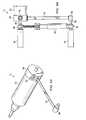
- FIGURE 3is a perspective view of one embodiment of a programmable tool for external fixator strut length adjustment.
- the programmable tool 10is used to adjust an external fixation device 50.
- the external fixation device 50includes numerous struts 52 separating a first 54 and a second 56 fixation rings. For simplicity, a portion of the external fixation device 50 including a portion of the first 54 and second 56 fixation rings separated by a single strut 52 is shown.
- the strut 52includes a strut adjustment mechanism 58 adapted to fit the strut fitting 30 of the programmable tool 10.
- the programmable tool 10includes a housing 12 having a front 14 and a back (not shown). The shape of the housing 12 may be in any shape and size convenient for use.
- the housing 12also has one or more data ports 18 that allow communication from the programmable tool 10 and an external source, e.g., computer, etc.
- the one or more data ports 18are connected to the internal circuitry (not shown) of the programmable tool 10.
- the housing 12has a power connection 16a and 16b to provide a source of external power to recharge the batteries (not shown) used to operate the programmable tool 10.
- the housing 12also includes a control board 22 that has various controls to allow the user to operate various functions of the device.
- the control board 22may include selectors for the specific struts, buttons to set the time, date, etc. and other selectors that allow programming or operation of various functions in conjunction with the display 20.
- the strut adjustment mechanism 58 of the strut 52is adapted to fit the strut fitting 30 of the programmable tool 10.
- the strut sensor 26identifies each individual specific strut 52 on the external fixation device and the programmable tool 10 then adjusts that strut 52 to the specific length prescribed by the treatment protocol. The procedure is repeated for each strut 52 of the external fixation device 50.
- the programmable tool 10updates the adjustment instructions stored in a memory unit in the microcontroller 34 (shown in FIGURE 2 ) with relevant information, such as the length of the strut after an adjustment, the amount of adjustment, or the number of times adjustments have been made.
- FIGURE 4is a perspective view of one embodiment of a strut number identifier of a programmable tool for external fixator strut length adjustment.
- the programmable tool 10is used to adjust a strut 52 separating a first (not shown) and a second (not shown) fixation rings.
- the strut 52includes a strut adjustment mechanism 58 adapted to fit the strut fitting 30 of the programmable tool 10.
- the programmable tool 10includes a housing 12 having a front and a back (not shown). The shape of the housing 12 may be in any shape and size convenient for use.
- the strut adjustment mechanism 58includes an indention 60 that is adapted to fit the strut fitting 30 to provide secure connection between the strut 52 and the programmable tool 10.
- Each of the specific strut 52includes a strut specific RF transmitter 62 that contains the necessary information for the specific strut 52.
- the programmable tool 10includes a RF sensor 64 that receives the information from the RF transmitter 62 to identify the specific strut 52.
- the RF sensor 64is in communication with the microcontroller module (not shown) and is used to automatically adjust the length of the strut 52.
- FIGURE 5is a perspective view of another embodiment of a strut number identifier of a programmable tool for external fixator strut length adjustment.
- the programmable tool 10is used to adjust a strut 52 separating a first (not shown) and a second (not shown) fixation rings.
- the strut 52includes a strut adjustment mechanism 58 adapted to fit the strut fitting 30 of the programmable tool 10.
- the strut adjustment mechanism 58includes an indention 60 that is adapted to fit the strut fitting 30 to provide secure connection between the strut 52 and the programmable tool 10.
- Each of the specific struts 52includes a strut specific bar code 66 that contains the identification information for the specific strut 52.
- the programmable tool 10includes a housing 12 having a front and a back (not shown).
- the shape of the housing 12may be in any shape and size convenient for use.
- the programmable tool 10includes a bar code reader 68 that reads the information from the bar code 66 to identify the specific strut 52.
- the bar code reader 68is in communication with the microcontroller module (not shown) and is used to automatically adjust the length of the strut 52.
- FIGURE 6is a perspective view of another embodiment of a strut number identifier of a programmable tool for external fixator strut length adjustment.
- the programmable tool 10is used to adjust a strut 52 separating a first (not shown) and a second (not shown) fixation rings.
- the strut 52includes a strut adjustment mechanism 58 adapted to fit the strut fitting 30 of the programmable tool 10.
- the strut adjustment mechanism 58includes an indention 60 that is adapted to fit the strut fitting 30 to provide secure connection between the strut 52 and the programmable tool 10.
- the strut 52also includes an strut identification device 70 for storing and providing strut identification information.
- the indention 60is adapted to include a first electrical contact 72 and/or a second electrical contact 74 connected to the strut identification device 70.
- the first and second contacts 72 and 74engage corresponding electrical contacts 76 and 78 of the programmable tool 10, respectively.
- the programmable tool 10includes the first electrical contact 76 and the second contact 78 for receiving/reading a signal from the strut identification device 70 via the first and second contact 72 and 74.
- the programmable tool 10is in communication with the microcontroller module (not shown) and is used to automatically adjust the length of the strut 52.
- FIGURE 7is a perspective view of another embodiment of a strut rotation encoder of a programmable tool for external fixator strut length adjustment.
- the programmable tool 10is used to adjust a strut 52 separating a first (not shown) and a second (not shown) fixation rings.
- the strut 52includes a strut adjustment mechanism 58 adapted to fit the strut fitting 30 of the programmable tool 10.
- the strut adjustment mechanism 58includes an indention 60 that is adapted to fit the strut fitting 30 to provide secure connection between the strut 52 and the programmable tool 10.
- the strut adjustment mechanism 58includes a magnetic ring 80 about the indention 60 and the strut fitting 30 of the programmable tool 10.
- the programmable tool 10includes a housing 12 having a front and a back (not shown).
- the shape of the housing 12may be in any shape and size convenient for use.
- the programmable tool 10includes a magnetic feedback sensor 82, which allows monitoring of the number of turns made by the strut adjustment mechanism 58. Since the number of turns can be correlated to the amount of length adjustment, corresponding change in length of the strut 52 can be determined.
- FIGURE 8is a perspective view of one embodiment of a digital ruler ( FIG. 8A ) of a programmable tool for external fixator strut length adjustment and a method of strut length measurement using a digital ruler ( FIG. 8B ).
- FIGURE 8Ais an image of another embodiment, the programmable tool 10 used to adjust a strut (not shown) to separate a first (not shown) and a second (not shown) fixation rings.
- the programmable tool 10includes a housing 12 having a front and a back (not shown).
- the housing 12may have a variety of connections ports, connectors, displays and controls (not shown).
- the housing 12also has one or more data ports (not shown) that allow communication between the programmable tool 10 and an external source, e.g., computer, etc (not shown).
- the housing 12includes a display (not shown) which may display various types of information.
- the housing 12also includes a control board (not shown) that has various controls to allow the user to operate various functions of the programmable tool 10.
- the control board (not shown)may also include an on/off switch (not shown) that may be used to operate the programmable tool 10.
- the housing 12has a rotating shaft (not shown) that extends from the housing 12 and terminates in a strut fitting (not shown) that allows the connection of the programmable tool 10 to an external fixation strut.
- the rotating shaft (not shown)may be enclosed in a separate covering leaving only the strut fitting (not shown) exposed and accessible, while protecting the actual rotating shaft (not shown).
- the programmable tool 10includes a measuring device 84 to measure the distance between the first strut fitting 30 and a second strut fitting 86 attached to a second strut fitting housing 88 that is separated by a measuring segment 90.
- the programmable tool 10is calibrated to allow the measuring device 84 to measure the length of the measuring segment 90 and in turn the distance separating the first strut fitting 30 and the second strut fitting 86.
- the distancemay be displayed on a display 92 and/or transmitted to the programmable tool 10 for automatic adjustment of the strut (not shown).
- FIGURE 8Bis an image of a programmable tool 10 in operation.
- the programmable tool 10used to adjust a strut 52 to move a first fixation ring 56 relative to a second fixation ring 54.
- the programmable tool 10includes a housing 12 having a front and a back (not shown).
- the housing 12has a first strut fitting 30 that allows the connection of the programmable tool 10 to a first ball joint 94 of an external fixation strut 52.
- the programmable tool 10includes a measuring device 84 to measure the distance between the first strut fitting 30 and a second strut fitting 86 that is separated by a measuring segment 90; the second strut fitting 86 is attached to a second strut fitting housing 88.
- the second strut fitting 86fits a second ball joint 96 of an external fixation strut 52.
- the programmable tool 10is calibrated to allow the measuring device 84 to measure the length of the measuring segment 90 and in turn the distance separating the first ball joint 94 and the second ball joint 96 and, therefore, the distance separating the first fixation ring 56 and the second fixation ring 54.
- the distancemay be displayed on a display 92 and/or transmitted to the programmable tool 10 for automatic adjustment of the strut (not shown).
- a methodfor adjusting the orientation of a first external support member relative to a second external support member, in which a plurality of adjustable struts connect the first and second external support members.
- the methodincludes providing a programmable tool, which can be any tool described in the present application.
- the programmable toolcomprises a controller 100 in electrical communication with a memory unit 102 and an actuator 104.
- the actuator 104is operable to engage the plurality of adjustable struts and adjust the length of the plurality of adjustable struts.
- the actuator 104is operable to engage and rotate a rotatable adjustment mechanism 112 of the struts to effect the desired length adjustment.
- the rotatable adjustment mechanism 112can include any adjustment mechanism described in or modified in accordance to the present disclosure.
- the methodfurther includes storing, in the memory unit 102, instructions 106 for adjusting the length of each of the plurality of adjustable struts to a desired length.
- the instructions 106includes a prescription table for bone realignment.
- the methodfurther includes receiving identification information 108 corresponding to the first adjustable strut.
- the identification information 108can include any information that is described in the present disclosure or known in the art for uniquely identifying one strut from the other struts.
- the identification information 108is provided from a signal emitter in the strut to a signal receiver 110 in the programmable tool.
- the methodfurther includes retrieving, from the memory unit 102, the instructions for adjusting the length of the identified strut based on the identification information 108 and activating the actuator 104 to adjust the length of the identified strut according to the retrieved instructions. As a result the identified strut is adjusted to a desired length.
- the programmable toolfurther includes a measuring device 118 for measuring the length of the plurality of adjustable struts
- the methodfurther includes determining the length of the first adjustable strut prior to and after adjusting the length of the first adjustable strut and confirming that the first strut has the desired length 114.
- informationsuch as the desired strut length 114 or the change in strut length 116 can be fed back to the controller 100 to be stored in the memory unit 102.
- the feedback information stored in the memory unit 102could be used by a doctor or a user as a record to verify that the instructions 106 have been carried out or to update or optimize the instructions 106.
- the present applicationprovides a method and a tool for incrementally adjusting the length of an external fixator strut or other connection rod of an external fixation device.
- the external fixation devicemay include a first external fixator ring and a second external fixator ring connected by one or more external fixator struts or connecting rods.
- there are a plurality of external fixator strutsthat include a first ball joint having a first ball stud extending from a first ball that is at least partially surrounded by a first ball cage.
- the first ball studattaches to an aperture in an outer or inner surface of the external fixator ring or other external support.
- the external fixation strutincludes a strut housing comprising an axial bore extending longitudinally from the ball cage and an adjustment sleeve slidably fitted within the axial bore of the strut housing and a sleeve fastener positioned to secure the adjustment sleeve to the strut housing.
- the adjustment sleeveadjusts coarse rapid longitudinal movement with respect to the strut housing and an adjustment mechanism positioned at one end of the adjustment sleeve and threadably connected to a threaded elongated member.
- the adjustment mechanismgradually adjusts longitudinally the threaded elongated member and a second ball joint connected to the threaded elongated member.
- the second ball jointincludes a second ball stud extending from a second ball that is at least partially surrounded by a second ball cage.
- the second ball studattaches to an aperture in an outer or inner surface of the external fixator ring or other external support.
- the present applicationincludes a tool that can incrementally adjust the overall end-to-end length of the external fixator strut or other connection rod of an external fixation device.
- the toolis adapted to engage the adjustment mechanism of the external fixator strut and rotate the adjustment mechanism the preprogrammed direction and amount of turns to adjust the position of the threaded elongated member relative to the adjustment mechanism of the external fixator strut and thereby automatically adjust the overall end-to-end length of the external fixator strut the prescribed amount.
- the present applicationalso includes a method of incrementally adjusting the overall end-to-end length of the external fixator strut or other connection rod of an external fixation device by programming a programmable tool with the direction and amount of external fixation strut adjustment, engaging a programmable tool to the adjustment mechanism of the strut and allowing the tool to turn the adjustment mechanism of the strut in pre-programmed direction and on the pre-programmed amount of adjustment.
- the toolis adapted to engage the adjustment mechanism of the external fixator strut and rotate the adjustment mechanism by the pre-programmed amount of turns to adjust the position of the threaded elongated member relative to the adjustment mechanism of the external fixator strut.
- the toolincludes a recognition mechanism for receiving identification information corresponding to the strut to be adjusted, and automatically identifying the strut based on the identification information. Upon recognizing the strut, the tool is operable to automatically adjust the overall end-to-end length of the external fixator strut the prescribed amount.
- the toolhas a housing, a strut number identifier, a microcontroller with an internal memory, a control board, a power source, a motor, a gear box and a rotating shaft that engages an adjustment mechanism of the external fixator strut.
- the toolis positioned in or about the adjustment mechanism of a first external fixator strut and activated.
- the tooluniquely identifies the external fixator strut and retrieves the direction and amount of length adjustment that should be performed for this external fixator strut.
- the toolmay be configured to identify and control struts from more than one external fixation device.
- the rotating shaftengages the adjustment mechanism of the external fixator strut and rotates the adjustment mechanism by the desired number of turns.
- the toolis then re-positioned about the adjustment mechanism of a second external fixator strut to repeat the process of strut length adjustment until all external fixator struts are adjusted.
- the strut number identifiermay include a variety of mechanisms known to the skilled artisan.
- One common method of identificationincludes a radiofrequency (RF) sensor that wirelessly communicates with a radio frequency transmitter (RFID) located on the adjustment mechanism of the external fixator strut.
- RFIDradio frequency transmitter
- Another strut number identifiermay include a bar code reader that counts a specific number of grooves on the adjustment mechanism of the external fixator strut or communicates with magnetic strip located on the adjustment mechanism of the external fixator strut.
- strut number identifierincludes a sensor that receives information from a touch memory button located on the adjustment mechanism of the external fixator strut. Another embodiment of the present disclosure provides that the strut number is determined manually and allow the tool to engage the adjustment mechanism and rotates the adjustment mechanism on the desired number of turns.
- the present applicationalso provides a microcontroller for the strut adjustment tool to handle the operations and computations and an internal memory storage unit to store struts adjustment related data and other necessary records.
- the memory storage unitmay be in the form of a non-volatile memory, magnetic memory, read only memory (ROM), electrically erasable and programmable read only memory (EEPROM) or firmware.
- the present applicationalso provides a control board with e.g., a display, a speaker and several control buttons to handle the operations and communication with the patient to perform an external fixator strut's adjustment with the programmable adjustment tool.
- a control boardwith e.g., a display, a speaker and several control buttons to handle the operations and communication with the patient to perform an external fixator strut's adjustment with the programmable adjustment tool.
- the present disclosuremay include a control board with a tool mode control button that allows switching between reading and adjustment modes.
- the present disclosuremay provide with different visual, audio, vibration and other signals indicating the status of the adjustment tool (e.g., start signal after strut number identification, adjustment end signal after completion of each length adjustment of the strut, battery recharge signal, emergency signal, adjustment time reminder and so forth).
- the toolmay be internally powered by a rechargeable battery connected to an external power source (AC, DC, Solar and so forth) through power supply connectors located on the housing of the tool.
- an external power sourceAC, DC, Solar and so forth
- the toolmay include a geared motor as well as other means to incrementally adjust the overall end-to-end length of the external fixator strut or other connection rod of an external fixation device.
- the toolmay provide electromagnetic impulses to push the elongating member of the strut out of the strut housing.
- the toolmay also have a shape-memory alloy string to push the elongating member of the strut out of the strut housing.
- the toolmay also include a data port (e.g., USB connector) or a wireless communication port (blue tooth, WiFi, IR, RF, and so forth).
- a data porte.g., USB connector
- a wireless communication portblue tooth, WiFi, IR, RF, and so forth.
- the toolmay be connected to data storage (e.g., a memory stick) or to a computer to download the information on prescribed direction and amount of length adjustments for each external fixator strut.
- this data transfermay be bi-directional to allow the downloading of specific strut length adjustment parameters (e.g., an actual time of strut adjustment, actual amount of strut adjustment, etc.) that were stored on the internal memory of the tool to memory storage or computer.
- the present applicationmay include a device for indicating the actual number of turns the rotating shaft of the tool performed during each adjustment.
- the adjustment toolmay include a rotational shaft encoder or other feedback sensor that counts the number of turns of the rotating shaft of the tool.
- the present applicationmay also include a device and method for indicating the actual number of turns the adjustment mechanism of the external fixator strut performed during each adjustment.
- the adjustment toolmay include a magnetic feedback sensor communicating with magnetic ring transmitter located on the adjustment mechanism of the external fixator strut that counts the number of turns of the adjustment mechanism of the external fixator strut.
- the present applicationmay also include a device and method for indicating the overall length of the external fixator strut.
- the present disclosuremay include a digital ruler or feedback sensor to determine the overall length and/or length adjustment amount of the external fixator strut.
- the present applicationmay also include a device and method for indicating the resistance during the adjustment of the external fixator strut.
- the present applicationmay include a feedback torque measurement sensor to monitor resistance during the adjustments of the external fixator strut and provide a turning profile.
- the programmable adjustment toolmay be in the form of a wrench, a clip or similar device that allows the contacting of the tool with the adjustment mechanism of the external fixator strut so that the tool is secured to the external fixator strut by itself.
- an electrical sensormay be provided which generates a signal when the specified target adjustment is obtained.
- the present applicationincludes conventional displays and alarms in combination to be activated upon attaining a specified target adjustment.
- the use and arrangement of these displays and alarms in handheld toolsare conventionally known to be simple, functionally reliable, and inexpensive.
- a displaycan be mechanically activated in a conventional manner, e.g., by an axially movable pin, a pivotably movably mounted bar, etc.
- an electrical sensorcan be used in a conventional manner to generate a signal when the specified target adjustment is obtained. Signals from the electronic sensor are evaluated in a known manner by an electronic circuit in order to trigger conventional acoustic or optical devices when the target torque is obtained.
Landscapes
- Health & Medical Sciences (AREA)
- Surgery (AREA)
- Life Sciences & Earth Sciences (AREA)
- Engineering & Computer Science (AREA)
- Molecular Biology (AREA)
- Animal Behavior & Ethology (AREA)
- Orthopedic Medicine & Surgery (AREA)
- Biomedical Technology (AREA)
- Heart & Thoracic Surgery (AREA)
- Medical Informatics (AREA)
- Veterinary Medicine (AREA)
- Nuclear Medicine, Radiotherapy & Molecular Imaging (AREA)
- General Health & Medical Sciences (AREA)
- Public Health (AREA)
- Mechanical Engineering (AREA)
- Oral & Maxillofacial Surgery (AREA)
- Pathology (AREA)
- Physics & Mathematics (AREA)
- Electromagnetism (AREA)
- Surgical Instruments (AREA)
Description
- The present application relates in general to the field of external fixation, and more specifically, to tools used for the adjustment of external fixator connection strut or other connection rods.
- Without limiting the scope of the disclosure, its background is described in connection with external fixation devices and specifically tools used for the adjustment of external fixator struts or other connection rods.
- Generally, external fixation devices are commonly used in a variety of surgical procedures including limb lengthening and deformity correction. The process involves a rigid framework comprising several rings that are placed externally around the limb and attached to bone segments using wires and half pins inserted into the bone segments and connected to the related sections of the external rigid framework. The opposite rings of the rigid framework are interconnected by either threaded or telescopic rods directly or in conjunction with uni-planar or multi-planar hinges, which allow the surgeon to adjust position of the rings relative to each other longitudinally, rotationally, horizontally or angularly over a period of time.
- For example, in limb lengthening, the bone is surgically divided into two segments and wires and half pins are inserted into bone segments above and below the surgical bone cut and attached to rings of a rigid framework interconnected by struts or threaded and telescopic connection rods. The rigid framework is used to gradually push the two bone segments apart longitudinally over a period of time (e.g., one millimeter a day). This allows the bone to gradually form in the gap between bone segments created by this distraction technique. Once the desired amount of lengthening is achieved (e.g., 5-6 cm), the external apparatus is stabilized into a fixed position and left on the bone segments until complete mineralization of the newly formed bone (e.g., 3-6 months, depending on the nature of pathology and amount of lengthening).
- Similarly, in deformity correction, the bone is surgically divided into two segments (usually at the apex of the deformity) and wires and half pins are inserted into bone segments above and below the surgical bone cut and attached to rings of a rigid framework. Opposite rings of the rigid framework are connected together by threaded rods with attached uni-planar or multi-planar hinges that are used to gradually push the two bone segments apart angularly over a period of time.
- One common fixation device is a circular metal structure known as the Ilizarov Apparatus. The Ilizarov apparatus, when used for limb lengthening or deformity correction, consists of several rings or arches that are placed externally around the limb and attached to surgically separated bone segments using wires and half pins. For limb lengthening, the opposite rings are interconnected directly by three or four threaded or telescopic rods that are regularly adjusted in length and allowed for gradual separation of bone segments longitudinally. For angular deformity correction, the opposite rings of the Ilizarov apparatus are connected by a pair of hinges that provide an axis of rotation for bone segments and one angular distractor that gradually pushes two rings and associated bone segments apart.
- Another common external fixation device is the Taylor Spatial Frame, which is a hexapod type of the external fixation device based on a Stewart platform but shares many components and features of the Ilizarov apparatus. The Taylor Spatial Frame consists of two external fixation rings attached to bone segments by wires and half pins and connected together by 6 telescopic struts with multi-planar hinges located at both ends of the strut. Each strut may be lengthened or shortened as necessary to either pull two interconnected ring segments towards each other or push them apart. Adjustment of strut length allows manipulating with bone segments acutely or gradually in 6 axes (e.g., lengthening/shortening external/internal rotation, anterior/posterior horizontal translation, medial/lateral horizontal translation, anterior/posterior angular translation, and medial/lateral angular translation) to perform limb lengthening and correct angular, translational and rotational deformities simultaneously.
- An amount of an external fixator strut or connection rod length adjustment depends on the amount of bone segment separation to produce a reliable distraction regenerate. Generally, for limb lengthening and deformity correction the optimal daily amount of bone segment separation was determined as 1 mm divided into at least 4 increments per day. Therefore in cases with limb lengthening using 3-4 parallel threaded or telescopic rods or deformity correction using one threaded or telescopic rod (e.g., Ilizarov apparatus), the length of each rod is adjusted 1/4 of a millimeter four times a day producing a total length increase of 1 mm per day. It has also been suggested that smaller movements using a high frequency rate of distraction (e.g., a rate of distraction of from 1/60 to 1/1440 of a
millimeter 60 to 1440 times a day) prevents soft tissue damage and produces even better results. - In cases with limb lengthening and deformity correction using six struts (e.g., Taylor Spatial Frame), the amount of daily strut length adjustment is calculated by special software. Once the apparatus is attached to the bone segments, numerous parameters such as rings diameter, initial strut length, strut location and so forth are entered into the software to characterize one ring position relative to another ring and position of bone segments relative to each other and to the rings. After calculation of the total amount of each strut length adjustment, the software provides a tabled instruction ("prescription") on the amount of each strut length adjustment that should be achieved per each increment including strut number, the exact amount of adjustment necessary and the time to make the adjustment. In most of the cases with deformity correction, the struts are adjusted in different directions (shortening/lengthening) and in the different amounts.
- External fixator strut (or other connection threaded or telescopic rod) length adjustments are usually made by the patient (parents) either by turning the adjustment knob of the struts or telescopic rods manually or by turning the nuts of the threaded rods with a regular (e.g., open end) wrench. This way of strut length adjustment is time consuming (e.g., due to loosening and retightening of the threaded rod nuts before and after each adjustment), does not provide precise length adjustment (e.g., due to difficulty to monitor small amounts of adjustments) and creates overall frame instability during adjustments (e.g., due to dimensional clearance between connection elements). Furthermore, the prescription for length adjustments can be complicated, and human errors are prone to occur during the course of a complicated prescription. Additionally, existing adjustment processes do not include any feedback to the doctors or patient to confirm the desired adjustments have been properly and accurately made.
- US patent application
US 2007/0085496 describes a powered surgical tool with a housing that contains a power generating unit such as a motor. A control module is disposed in a shell that is mounted in the housing. The control module contains a control circuit for regulating the actuation of the power generating unit. The power generating unit emits a signal representative of the operating state of the unit that is transmitted through the structural material forming the shell. Also internal to the control module shell is a sensor that monitors the signal emitted by the power generating unit. This signal output by the sensor is applied to the control circuit. The control circuit, based on the sensor signal regulates actuation of the power generating unit. Wherein the power generating unit is a motor, the signal emitted is the magnetic field that varies with rotor position. The sensor monitors the strength of this field. - US patent application
US 2006/0207118 describes a depth gauge for measuring the depth of a hole in a bone is disclosed having a digital readout for providing the measurement to a surgeon. The depth gauge has a probe with a tip inserted into and positioned proximate to the depth the hole, and has a reference member adjustably positioned relative the probe and against the bone proximate the hole. A measuring device is provided with the depth gauge for measuring the relative distance between the tip and the reference member, and the measuring device has a large, digital display for providing the relative distance. - US patent application
US 2002/0010465 describes a frame fixator and operation system thereof, the fixator comprising an upper end ring and a lower end ring, and a plurality of length adjustment means coupled at both ends thereof to the upper end ring and the lower end ring, wherein the length adjustment means include an actuator, a moving member movable by the actuator and a digital indicator for indicating a length of the length adjustment means changeable to the movement of the moving member, the fixator and operation system for enabling to automatically adjust a distraction rate and distraction frequency of fracture during bone deformity correction and lengthening and to easily adjust the length by digitally indicating changed value of length according to manual or automatic manipulation. - As a consequence of the foregoing, a longstanding need exists among users for an apparatus that more precisely controls the incremental adjustment in length of the external fixator struts or other connection rods.
The invention is set out according to claim 1 of the appended claims whereas embodiments of the invention are set out according to the appended claims hereto. - The present application describes a programmable tool for incrementally adjusting the length of the external fixator strut or other connection rod of an external fixation device. The tool has a housing, a strut identifier, a microcontroller with an internal memory, a control board, a power source, a motor, a gear box and a rotating shaft and is adapted to engage the adjustment mechanism of the external fixator strut and rotate the adjustment mechanism the preprogrammed direction and amount of turns to adjust the position of the threaded elongated member relative to the adjustment mechanism of the external fixator strut and thereby automatically adjust the overall end-to-end length of the external fixator strut the prescribed amount.
- The present application describes a programmable tool for adjusting an external fixation strut. The programmable tool includes a power supply disposed in the housing, a data port disposed at least partially within the housing, and a signal-sensor disposed at least partially within the housing for receiving a signal from an external source. A motor is disposed within the housing and a gear box positioned between an output shaft and the motor with a strut fitting is adapted to fit an external fixation strut in operable communication with the output shaft motor for adjusting the external fixation strut. A controller is in electrical communication with the data port, the signal-sensor, the power supply and the motor. Also described is a memory unit in electrical communication with the controller to store one or more strut adjustment parameters, a display in electrical communication with the controller and a control panel in electrical communication with the controller to control one or more operations of the programmable tool.
- The present application also describes a programmable tool for adjusting an external fixation strut having a data port disposed at least partially within the housing, a signal-sensor disposed at least partially within the housing for receiving a signal from an external source, a power supply, a motor disposed within the housing, an output shaft comprising a strut fitting in operable communication with the motor, wherein the strut fitting is adapted to fit an external fixation strut and a controller in electrical communication with the data port, the signal-sensor, the power supply and the motor.
- Described in the present disclosure is a method, not forming part of the invention, which includes adjusting the orientation of a first external support member relative to a second external support member, in which a plurality of adjustable struts connect the first and second external support members. The plurality of struts include a first adjustable strut having an initial length, and the method includes providing a programmable tool, the programmable tool comprising a controller in electrical communication with a memory unit and an actuator. The actuator is operable to engage the plurality of adjustable struts and adjust the length of the plurality of adjustable struts. The method further includes storing, in the memory unit, instructions for adjusting the length of each of the plurality of adjustable struts to a desired length. The method further includes receiving identification information corresponding to the first adjustable strut, and retrieving, from the memory unit, the instructions for adjusting the length of the first adjustable strut based on the identification information corresponding to the first adjustable strut. Finally, the disclosed method includes activating the actuator to adjust the length of the first adjustable strut according to the retrieved instructions.
- In an example not forming part of the invention, the programmable tool may further include a measuring device for measuring the length of the plurality of adjustable struts, and determining the length of the first adjustable strut prior to and after adjusting the length of the first adjustable strut; and confirming that the first strut has the desired length. In an exemplary, the measuring device is a digital rule.
- For a more complete understanding of the features and advantages of the present disclosure, reference is now made to the detailed description of the disclosure along with the accompanying figures and in which:
FIGURE 1 is a perspective view of one embodiment of a programmable tool for external fixator strut length adjustment.FIGURE 2 is a cross sectional view of one embodiment of a programmable tool for external fixator strut length adjustment.FIGURE 3 is a perspective view of one embodiment of a programmable tool for external fixator strut length adjustment.FIGURE 4 is a perspective view of one embodiment of a strut number identifier of a programmable tool for external fixator strut length adjustment.FIGURE 5 is a perspective view of one embodiment of a strut number identifier of a programmable tool for external fixator strut length adjustment.FIGURE 6 is a perspective view of one embodiment of a strut number identifier of a programmable tool for external fixator strut length adjustment.FIGURE 7 is a perspective view of one embodiment of a strut rotation encoder of a programmable tool for external fixator strut length adjustment.FIGURE 8 is a perspective view of one embodiment of a digital ruler (A) of a programmable tool for external fixator strut length adjustment and a method of strut length measurement using a digital ruler (B).FIGURE 9 is a schematic block diagram of a method of adjusting an external fixation strut.- The specific embodiments discussed herein are merely illustrative of specific ways to make and use the disclosure and do not delimit the scope of the disclosure.
FIGURE 1 is a perspective view of one embodiment of a programmable tool for external fixator strut length adjustment. Theprogrammable tool 10 includes ahousing 12 having a front 14 and a back (not shown). The shape of thehousing 12 may be in any shape and size convenient for use. For example, thehousing 12 may be cylindrical in shape, square in shape, ergonomic in shape etc. and may be of a size convenient for use by children or adults. In addition, the housing may be ergonomically shaped or shaped and sized for use by the elderly, handicapped or disabled.- The housing may have a variety of connections ports, connectors, displays and controls. For example in one embodiment the
housing 12 has apower connection programmable tool 10. Thepower connection power connection housing 12, the skilled artisan will recognize that thepower connection programmable tool 10. Alternatively, thepower connection housing 12 so that they may be easily removed, recharged and replaced. Alternatively, the batteries may be disposable and replaced as necessary. Theprogrammable tool 10 may also have an internal battery and/or memory storage device to retain information in memory in case of a loss in power. Generally, the power source can be a battery, a solar panel, a layer of piezoelectric film or any type of energy harvesting technology. The power source can also be a combination of a battery along with one of the voltage generators connected to a power controller to manage power consumption and storage in the battery. - The
housing 12 also has one ormore data ports 18 that allow communication between theprogrammable tool 10 and an external source, e.g., computer, etc. The one or more communication ordata ports 18 are connected to the internal circuitry (not shown) of theprogrammable tool 10. Generally, the one ormore data ports 18 are in communication with the controller. The present application comprises a microcontroller, processor, microprocessor or analog circuit or logic circuit, an external sensor, a sensor reader, a transmitter, a receiver, output interface, a battery, a motor, a gearbox, a data storage, a memory, a communication device/port, a data port, or other components. In addition, the microprocessor determines whether one or more operational parameters are within one or more guidelines, the specific strut, the specific length of the strut, the specific location of the strut and determines the output necessary given the specific treatment regiment. The processor or analog circuit can receive instructions and/or relay information to and from medical service providers via the communications port. The processor or analog circuit can direct output to the motor and/or the display as necessary. - The one or
more data ports 18 may be in the form of a USB port, mini port, micro port RS232 port, telephone connection port, Ethernet port, CAT 5 connection port, or other port known to the skilled artisan to allow transfer of information and data in a uni-, bi- or multi-directional manner. Although, the one ormore data ports 18 are shown in the form of a physical connection, the skilled artisan will immediately recognize that other forms of communication are acceptable. For example, the one ormore data ports 18 may be in the form of an internal modem, cellular modem, Wi-Fi module, Bluetooth module, IR module, RF module, RFID module and other methods known to the skilled artisan to allow transfer of information and data in a uni-, bi-or multi-directional manner. - The
housing 12 includes adisplay 20 which may display various types of information. For example, thedisplay 20 may be in the form of a visual display (e.g., LCD, LEDs, Arrays of LEDs, or other visual display known to those skilled in the art), a speaker, a multi-tone generator, a communications interface or a combination thereof. The visual display can be a set of light emitting diodes that provide a feedback to the user, a status of the strut, other relevant information or a combination thereof. - The
housing 12 also includes acontrol board 22 that has various controls to allow the user to operate various functions of the device. For example, thecontrol board 22 may include selectors for the specific struts, buttons to set the time, date, etc. and other selectors that allow programming or operation of various functions in conjunction with thedisplay 20. Thecontrol board 22 may also include an on/offswitch 24 that may be used to operate theprogrammable tool 10. - A
strut sensor 26 is incorporated into thehousing 12 to allow the automatic recognition of the specific strut to be adjusted. In some embodiments, each strut includes a device for providing a signal that embodies an unique identification code. The strut sensor either wirelessly or electrically communicates with the signal emitting device to receive the unique identification code. The unique identification code allows theprogrammable tool 10 to recognize and identify the strut, and may be in various forms described in the present disclosure or known in the art. For example, thestrut sensor 26 may be an RFID sensor that receives a unique radiofrequency identification code from the strut to identify the strut on the external fixation device. In some embodiments where multiple external fixation devices are used (either on a single individual or multiple individuals), thestrut sensor 26 may identify the individual and each specific strut on the external fixation device. As such, the use of an unique identification code allows the use of a singleprogrammable tool 10 with numerous individuals and/or numerous external fixation devices. - The
housing 12 has arotating shaft 28 that extends from thehousing 12 and terminates in a strut fitting 30 that allows the connection of theprogrammable tool 10 to the external fixation strut. The rotatingshaft 28 may be enclosed in a separate covering leaving only the strut fitting 30 exposed and accessible, while protecting the actualrotating shaft 28. FIGURE 2 is a cross sectional view of one embodiment of a programmable tool for external fixator strut length adjustment. Thehousing 12 may be sized to fit a variety of individual modules. For example, the housing may include adata port 18 accessible from the exterior of theprogrammable tool 10 and in communication with adata module 32. In some embodiments, thedata module 32 stores instructions for adjusting the struts. For example, a prescription table may be received and stored in thedata module 32 for later retrieval. Thedata module 32 is in communication with amicrocontroller 34 that includes numerous functions and components. Themicrocontroller module 34 includes an input/output (not shown) connection internal memory (not shown) or a connection to external memory (not shown), a CPU, a memory/data storage unit (not shown) and so forth. The data storage can be used to store the one or more parameters, the feedback, a status, diagnostic information or a combination thereof. The data storage can be a REID tag, a magnetic strip, a memory or a combination thereof. Apower source 36 is contained within thehousing 12 to provide an internal source of power to drive the internal components and various modules. Thepower source 36 may be an internal battery, replaceable battery, rechargeable battery, generator, chemical cell or other source known to the skilled artisan. Alternatively, thepower source 36 may be directly connected to an external power source e.g., 12v source, electrical outlet, USB port, computer battery or other source of electrical power.- A
motor module 38 is also contained within thehousing 12 and in communication with the various modules. Themotor 38 includes anoutput shaft 40 for transferring the energy to one or more sets of gears (not shown) located ingear box 42. Thegear box 42 also includes an output shaft that is ultimately used to drive the rotatingshaft 28 and strut fitting 30. A rotational shaft,encoder 46 and astrut identifier module 48 may be located between themotor module 38 and the strut fitting 30. Therotational shaft encoder 46 collects data relating to the rotation of therotating shaft 28 or various output shafts (not shown). In addition, the programmable tool may include an integral torque sensor and limiter which measures the amount of torque and limits the torque that can be transmitted by themotor module 38 to therotating shaft 28 in known fashion, e.g. by switching off themotor module 38 in the case of anelectric motor module 38 or in a similar manner. Alternatively thegear box 42 or themotor module 38 may include a clutch mechanism to limit the torque supplied to therotating shaft 28. FIGURE 3 is a perspective view of one embodiment of a programmable tool for external fixator strut length adjustment. In operation, theprogrammable tool 10 is used to adjust anexternal fixation device 50. Theexternal fixation device 50 includesnumerous struts 52 separating a first 54 and a second 56 fixation rings. For simplicity, a portion of theexternal fixation device 50 including a portion of the first 54 and second 56 fixation rings separated by asingle strut 52 is shown. Thestrut 52 includes astrut adjustment mechanism 58 adapted to fit the strut fitting 30 of theprogrammable tool 10. Theprogrammable tool 10 includes ahousing 12 having a front 14 and a back (not shown). The shape of thehousing 12 may be in any shape and size convenient for use. Thehousing 12 also has one ormore data ports 18 that allow communication from theprogrammable tool 10 and an external source, e.g., computer, etc. The one ormore data ports 18 are connected to the internal circuitry (not shown) of theprogrammable tool 10. For example, in one embodiment thehousing 12 has apower connection programmable tool 10. Thehousing 12 also includes acontrol board 22 that has various controls to allow the user to operate various functions of the device. For example, thecontrol board 22 may include selectors for the specific struts, buttons to set the time, date, etc. and other selectors that allow programming or operation of various functions in conjunction with thedisplay 20.- In operation, the
strut adjustment mechanism 58 of thestrut 52 is adapted to fit the strut fitting 30 of theprogrammable tool 10. Thestrut sensor 26 identifies each individualspecific strut 52 on the external fixation device and theprogrammable tool 10 then adjusts thatstrut 52 to the specific length prescribed by the treatment protocol. The procedure is repeated for eachstrut 52 of theexternal fixation device 50. In some embodiments, after making the length adjustments, theprogrammable tool 10 updates the adjustment instructions stored in a memory unit in the microcontroller 34 (shown inFIGURE 2 ) with relevant information, such as the length of the strut after an adjustment, the amount of adjustment, or the number of times adjustments have been made. FIGURE 4 is a perspective view of one embodiment of a strut number identifier of a programmable tool for external fixator strut length adjustment. In operation, theprogrammable tool 10 is used to adjust astrut 52 separating a first (not shown) and a second (not shown) fixation rings. Thestrut 52 includes astrut adjustment mechanism 58 adapted to fit the strut fitting 30 of theprogrammable tool 10. Theprogrammable tool 10 includes ahousing 12 having a front and a back (not shown). The shape of thehousing 12 may be in any shape and size convenient for use. Thestrut adjustment mechanism 58 includes anindention 60 that is adapted to fit the strut fitting 30 to provide secure connection between thestrut 52 and theprogrammable tool 10. Each of thespecific strut 52 includes a strutspecific RF transmitter 62 that contains the necessary information for thespecific strut 52. Theprogrammable tool 10 includes aRF sensor 64 that receives the information from theRF transmitter 62 to identify thespecific strut 52. TheRF sensor 64 is in communication with the microcontroller module (not shown) and is used to automatically adjust the length of thestrut 52.FIGURE 5 is a perspective view of another embodiment of a strut number identifier of a programmable tool for external fixator strut length adjustment. In this embodiment, theprogrammable tool 10 is used to adjust astrut 52 separating a first (not shown) and a second (not shown) fixation rings. Thestrut 52 includes astrut adjustment mechanism 58 adapted to fit the strut fitting 30 of theprogrammable tool 10. Thestrut adjustment mechanism 58 includes anindention 60 that is adapted to fit the strut fitting 30 to provide secure connection between thestrut 52 and theprogrammable tool 10. Each of thespecific struts 52 includes a strutspecific bar code 66 that contains the identification information for thespecific strut 52. Theprogrammable tool 10 includes ahousing 12 having a front and a back (not shown). The shape of thehousing 12 may be in any shape and size convenient for use. Theprogrammable tool 10 includes abar code reader 68 that reads the information from thebar code 66 to identify thespecific strut 52. Thebar code reader 68 is in communication with the microcontroller module (not shown) and is used to automatically adjust the length of thestrut 52.FIGURE 6 is a perspective view of another embodiment of a strut number identifier of a programmable tool for external fixator strut length adjustment. In this embodiment, theprogrammable tool 10 is used to adjust astrut 52 separating a first (not shown) and a second (not shown) fixation rings. Thestrut 52 includes astrut adjustment mechanism 58 adapted to fit the strut fitting 30 of theprogrammable tool 10. Thestrut adjustment mechanism 58 includes anindention 60 that is adapted to fit the strut fitting 30 to provide secure connection between thestrut 52 and theprogrammable tool 10. Thestrut 52 also includes anstrut identification device 70 for storing and providing strut identification information. Theindention 60 is adapted to include a firstelectrical contact 72 and/or a secondelectrical contact 74 connected to thestrut identification device 70. The first andsecond contacts electrical contacts programmable tool 10, respectively. Theprogrammable tool 10 includes the firstelectrical contact 76 and thesecond contact 78 for receiving/reading a signal from thestrut identification device 70 via the first andsecond contact programmable tool 10 is in communication with the microcontroller module (not shown) and is used to automatically adjust the length of thestrut 52.FIGURE 7 is a perspective view of another embodiment of a strut rotation encoder of a programmable tool for external fixator strut length adjustment. In this embodiment, theprogrammable tool 10 is used to adjust astrut 52 separating a first (not shown) and a second (not shown) fixation rings. Thestrut 52 includes astrut adjustment mechanism 58 adapted to fit the strut fitting 30 of theprogrammable tool 10. Thestrut adjustment mechanism 58 includes anindention 60 that is adapted to fit the strut fitting 30 to provide secure connection between thestrut 52 and theprogrammable tool 10. Thestrut adjustment mechanism 58 includes amagnetic ring 80 about theindention 60 and the strut fitting 30 of theprogrammable tool 10. Theprogrammable tool 10 includes ahousing 12 having a front and a back (not shown). The shape of thehousing 12 may be in any shape and size convenient for use. Theprogrammable tool 10 includes amagnetic feedback sensor 82, which allows monitoring of the number of turns made by thestrut adjustment mechanism 58. Since the number of turns can be correlated to the amount of length adjustment, corresponding change in length of thestrut 52 can be determined.FIGURE 8 is a perspective view of one embodiment of a digital ruler (FIG. 8A ) of a programmable tool for external fixator strut length adjustment and a method of strut length measurement using a digital ruler (FIG. 8B ).FIGURE 8A is an image of another embodiment, theprogrammable tool 10 used to adjust a strut (not shown) to separate a first (not shown) and a second (not shown) fixation rings. Theprogrammable tool 10 includes ahousing 12 having a front and a back (not shown). Thehousing 12 may have a variety of connections ports, connectors, displays and controls (not shown). Thehousing 12 also has one or more data ports (not shown) that allow communication between theprogrammable tool 10 and an external source, e.g., computer, etc (not shown). Thehousing 12 includes a display (not shown) which may display various types of information. Thehousing 12 also includes a control board (not shown) that has various controls to allow the user to operate various functions of theprogrammable tool 10. The control board (not shown) may also include an on/off switch (not shown) that may be used to operate theprogrammable tool 10. Thehousing 12 has a rotating shaft (not shown) that extends from thehousing 12 and terminates in a strut fitting (not shown) that allows the connection of theprogrammable tool 10 to an external fixation strut. The rotating shaft (not shown) may be enclosed in a separate covering leaving only the strut fitting (not shown) exposed and accessible, while protecting the actual rotating shaft (not shown). Theprogrammable tool 10 includes a measuringdevice 84 to measure the distance between the first strut fitting 30 and a second strut fitting 86 attached to a secondstrut fitting housing 88 that is separated by a measuringsegment 90. Theprogrammable tool 10 is calibrated to allow the measuringdevice 84 to measure the length of the measuringsegment 90 and in turn the distance separating the first strut fitting 30 and the second strut fitting 86. The distance may be displayed on adisplay 92 and/or transmitted to theprogrammable tool 10 for automatic adjustment of the strut (not shown).FIGURE 8B is an image of aprogrammable tool 10 in operation. Theprogrammable tool 10 used to adjust astrut 52 to move afirst fixation ring 56 relative to asecond fixation ring 54. Theprogrammable tool 10 includes ahousing 12 having a front and a back (not shown). Thehousing 12 has a first strut fitting 30 that allows the connection of theprogrammable tool 10 to a first ball joint 94 of anexternal fixation strut 52. Theprogrammable tool 10 includes a measuringdevice 84 to measure the distance between the first strut fitting 30 and a second strut fitting 86 that is separated by a measuringsegment 90; the second strut fitting 86 is attached to a secondstrut fitting housing 88. The second strut fitting 86 fits a second ball joint 96 of anexternal fixation strut 52. Theprogrammable tool 10 is calibrated to allow the measuringdevice 84 to measure the length of the measuringsegment 90 and in turn the distance separating the first ball joint 94 and the second ball joint 96 and, therefore, the distance separating thefirst fixation ring 56 and thesecond fixation ring 54. The distance may be displayed on adisplay 92 and/or transmitted to theprogrammable tool 10 for automatic adjustment of the strut (not shown).- To facilitate the understanding of this application, a number of terms are defined below. Terms defined herein have meanings commonly understood by a person of ordinary skill in the areas relevant to the present application. Terms such as "a", "an" and "the" are not intended to refer to only a singular entity, but include the general class of which a specific example may be used for illustration. The terminology herein is used to describe specific embodiments of the disclosure, but their usage does not delimit the disclosure, except as outlined in the claims.
- Referring to
Figure 9 , a method is described for adjusting the orientation of a first external support member relative to a second external support member, in which a plurality of adjustable struts connect the first and second external support members. The method includes providing a programmable tool, which can be any tool described in the present application. In some embodiments, the programmable tool comprises acontroller 100 in electrical communication with amemory unit 102 and anactuator 104. Theactuator 104 is operable to engage the plurality of adjustable struts and adjust the length of the plurality of adjustable struts. In some embodiment, theactuator 104 is operable to engage and rotate arotatable adjustment mechanism 112 of the struts to effect the desired length adjustment. Therotatable adjustment mechanism 112 can include any adjustment mechanism described in or modified in accordance to the present disclosure. The method further includes storing, in thememory unit 102,instructions 106 for adjusting the length of each of the plurality of adjustable struts to a desired length. In some embodiments, theinstructions 106 includes a prescription table for bone realignment. The method further includes receivingidentification information 108 corresponding to the first adjustable strut. Theidentification information 108 can include any information that is described in the present disclosure or known in the art for uniquely identifying one strut from the other struts. In some embodiments, theidentification information 108 is provided from a signal emitter in the strut to asignal receiver 110 in the programmable tool. The method further includes retrieving, from thememory unit 102, the instructions for adjusting the length of the identified strut based on theidentification information 108 and activating theactuator 104 to adjust the length of the identified strut according to the retrieved instructions. As a result the identified strut is adjusted to a desired length. - In some embodiments, the programmable tool further includes a
measuring device 118 for measuring the length of the plurality of adjustable struts, and the method further includes determining the length of the first adjustable strut prior to and after adjusting the length of the first adjustable strut and confirming that the first strut has the desiredlength 114. In some embodiments, information such as the desiredstrut length 114 or the change instrut length 116 can be fed back to thecontroller 100 to be stored in thememory unit 102. In yet some other embodiments, the feedback information stored in thememory unit 102 could be used by a doctor or a user as a record to verify that theinstructions 106 have been carried out or to update or optimize theinstructions 106. - The present application provides a method and a tool for incrementally adjusting the length of an external fixator strut or other connection rod of an external fixation device. The external fixation device may include a first external fixator ring and a second external fixator ring connected by one or more external fixator struts or connecting rods. In some embodiments, there are a plurality of external fixator struts that include a first ball joint having a first ball stud extending from a first ball that is at least partially surrounded by a first ball cage. The first ball stud attaches to an aperture in an outer or inner surface of the external fixator ring or other external support. The external fixation strut includes a strut housing comprising an axial bore extending longitudinally from the ball cage and an adjustment sleeve slidably fitted within the axial bore of the strut housing and a sleeve fastener positioned to secure the adjustment sleeve to the strut housing. The adjustment sleeve adjusts coarse rapid longitudinal movement with respect to the strut housing and an adjustment mechanism positioned at one end of the adjustment sleeve and threadably connected to a threaded elongated member. The adjustment mechanism gradually adjusts longitudinally the threaded elongated member and a second ball joint connected to the threaded elongated member. The second ball joint includes a second ball stud extending from a second ball that is at least partially surrounded by a second ball cage. The second ball stud attaches to an aperture in an outer or inner surface of the external fixator ring or other external support.
- The present application includes a tool that can incrementally adjust the overall end-to-end length of the external fixator strut or other connection rod of an external fixation device. The tool is adapted to engage the adjustment mechanism of the external fixator strut and rotate the adjustment mechanism the preprogrammed direction and amount of turns to adjust the position of the threaded elongated member relative to the adjustment mechanism of the external fixator strut and thereby automatically adjust the overall end-to-end length of the external fixator strut the prescribed amount.
- The present application also includes a method of incrementally adjusting the overall end-to-end length of the external fixator strut or other connection rod of an external fixation device by programming a programmable tool with the direction and amount of external fixation strut adjustment, engaging a programmable tool to the adjustment mechanism of the strut and allowing the tool to turn the adjustment mechanism of the strut in pre-programmed direction and on the pre-programmed amount of adjustment. The tool is adapted to engage the adjustment mechanism of the external fixator strut and rotate the adjustment mechanism by the pre-programmed amount of turns to adjust the position of the threaded elongated member relative to the adjustment mechanism of the external fixator strut. In some embodiments, the tool includes a recognition mechanism for receiving identification information corresponding to the strut to be adjusted, and automatically identifying the strut based on the identification information. Upon recognizing the strut, the tool is operable to automatically adjust the overall end-to-end length of the external fixator strut the prescribed amount.
- In one embodiment, the tool has a housing, a strut number identifier, a microcontroller with an internal memory, a control board, a power source, a motor, a gear box and a rotating shaft that engages an adjustment mechanism of the external fixator strut. In operation, the tool is positioned in or about the adjustment mechanism of a first external fixator strut and activated. The tool uniquely identifies the external fixator strut and retrieves the direction and amount of length adjustment that should be performed for this external fixator strut. In some embodiments, the tool may be configured to identify and control struts from more than one external fixation device. The rotating shaft engages the adjustment mechanism of the external fixator strut and rotates the adjustment mechanism by the desired number of turns. The tool is then re-positioned about the adjustment mechanism of a second external fixator strut to repeat the process of strut length adjustment until all external fixator struts are adjusted.
- The strut number identifier may include a variety of mechanisms known to the skilled artisan. One common method of identification includes a radiofrequency (RF) sensor that wirelessly communicates with a radio frequency transmitter (RFID) located on the adjustment mechanism of the external fixator strut. Another strut number identifier may include a bar code reader that counts a specific number of grooves on the adjustment mechanism of the external fixator strut or communicates with magnetic strip located on the adjustment mechanism of the external fixator strut. In another embodiment, strut number identifier includes a sensor that receives information from a touch memory button located on the adjustment mechanism of the external fixator strut. Another embodiment of the present disclosure provides that the strut number is determined manually and allow the tool to engage the adjustment mechanism and rotates the adjustment mechanism on the desired number of turns.
- The present application also provides a microcontroller for the strut adjustment tool to handle the operations and computations and an internal memory storage unit to store struts adjustment related data and other necessary records. The memory storage unit may be in the form of a non-volatile memory, magnetic memory, read only memory (ROM), electrically erasable and programmable read only memory (EEPROM) or firmware.
- The present application also provides a control board with e.g., a display, a speaker and several control buttons to handle the operations and communication with the patient to perform an external fixator strut's adjustment with the programmable adjustment tool. For example, the present disclosure may include a control board with a tool mode control button that allows switching between reading and adjustment modes. In addition, the present disclosure may provide with different visual, audio, vibration and other signals indicating the status of the adjustment tool (e.g., start signal after strut number identification, adjustment end signal after completion of each length adjustment of the strut, battery recharge signal, emergency signal, adjustment time reminder and so forth).
- The tool may be internally powered by a rechargeable battery connected to an external power source (AC, DC, Solar and so forth) through power supply connectors located on the housing of the tool.
- The tool may include a geared motor as well as other means to incrementally adjust the overall end-to-end length of the external fixator strut or other connection rod of an external fixation device. For example, the tool may provide electromagnetic impulses to push the elongating member of the strut out of the strut housing. The tool may also have a shape-memory alloy string to push the elongating member of the strut out of the strut housing.
- The tool may also include a data port (e.g., USB connector) or a wireless communication port (blue tooth, WiFi, IR, RF, and so forth). Using the data port or wireless communication port, the tool may be connected to data storage (e.g., a memory stick) or to a computer to download the information on prescribed direction and amount of length adjustments for each external fixator strut. In addition, this data transfer may be bi-directional to allow the downloading of specific strut length adjustment parameters (e.g., an actual time of strut adjustment, actual amount of strut adjustment, etc.) that were stored on the internal memory of the tool to memory storage or computer.
- The present application may include a device for indicating the actual number of turns the rotating shaft of the tool performed during each adjustment. For example, the adjustment tool may include a rotational shaft encoder or other feedback sensor that counts the number of turns of the rotating shaft of the tool.
- The present application may also include a device and method for indicating the actual number of turns the adjustment mechanism of the external fixator strut performed during each adjustment. For example, the adjustment tool may include a magnetic feedback sensor communicating with magnetic ring transmitter located on the adjustment mechanism of the external fixator strut that counts the number of turns of the adjustment mechanism of the external fixator strut.
- In addition, the present application may also include a device and method for indicating the overall length of the external fixator strut. For example, the present disclosure may include a digital ruler or feedback sensor to determine the overall length and/or length adjustment amount of the external fixator strut.
- In addition, the present application may also include a device and method for indicating the resistance during the adjustment of the external fixator strut. For example, the present application may include a feedback torque measurement sensor to monitor resistance during the adjustments of the external fixator strut and provide a turning profile.
- The programmable adjustment tool may be in the form of a wrench, a clip or similar device that allows the contacting of the tool with the adjustment mechanism of the external fixator strut so that the tool is secured to the external fixator strut by itself.
- In addition to or instead of the displays, an electrical sensor may be provided which generates a signal when the specified target adjustment is obtained. The present application includes conventional displays and alarms in combination to be activated upon attaining a specified target adjustment. The use and arrangement of these displays and alarms in handheld tools are conventionally known to be simple, functionally reliable, and inexpensive. For example, a display can be mechanically activated in a conventional manner, e.g., by an axially movable pin, a pivotably movably mounted bar, etc. Additionally or alternatively, an electrical sensor can be used in a conventional manner to generate a signal when the specified target adjustment is obtained. Signals from the electronic sensor are evaluated in a known manner by an electronic circuit in order to trigger conventional acoustic or optical devices when the target torque is obtained.
Claims (11)
- A programmable tool (10) operable to adjust an external fixation strut (52) having a rotatable adjustment mechanism (58) for length adjustments and a strut identifier (62) operable to provide a signal that identifies the external fixation strut (52), the programmable tool (10) comprising:a housing (12);a power supply (36) disposed in the housing (12);a data port (18) disposed at least partially within the housing (12), the data port (18) operable to receive instructions for adjusting the external fixation strut;a signal-sensor (26) disposed at least partially within the housing (12), the signal-sensor (26) operable to receive the signal from the strut identifier (62);a motor (38) disposed within the housing (12); andan output shaft (28, 40) driven by the motor (38), the output shaft (40) comprising a strut fitting (30) adapted to engage and rotate the rotatable adjustment mechanism (58) of the external fixation strut;a controller (100) in electrical communication with the data port (18), the signal-sensor, the power supply (36) and the motor; anda memory unit (102) in electrical communication with the controller (100), the memory unit operable to store data, whereinthe controller (100) is configured to retrieve, from the memory unit (102), instructions for adjusting a length of the external fixation strut (52) based on the signal received from the strut identifier by the signal-sensor, and to activate the motor to adjust the length of the external fixation strut according to the retrieved instructions.
- The tool of claim 1, wherein:the output shaft comprises a first output shaft (40) a second output shaft and a rotating shaft (28);the tool (10) comprises a gear box (42) comprising one or more sets of gears driven by the first output shaft (40), wherein the one or more sets of gears drive the second output shaft; andthe rotating shaft (28) is coupled to the second output shaft, the rotating shaft (28) comprising the strut fitting (30).
- The tool of claim 1 or of claim 2, further comprising a display (20) in electrical communication with the controller (100).
- The tool of claim 3, wherein the display (20) comprises a LCD display, a LED display, an array of LEDs, a speaker, a multi-tone generator, a communication interface or a combination thereof.
- The tool of claim 1 or claim 2, wherein the data port comprises a USB port, an RS232 port, a modem port, cellular modem, a Wi-Fi module, a Bluetooth module, an IR module, an RF module, an RFID module or combination thereof.
- The tool of claim 1, or claim 2, wherein the signal-sensor comprises a barcode reader, a Bluetooth receiver, an IR receiver, an RF receiver, an RFID receiver, magnetic decoder or combination thereof.
- The tool of claim 1 or claim 2, wherein the power supply (36) comprises a battery, a DC source, a AC source or a combination thereof.
- The tool of claim 1 or claim 2 wherein the power supply (36) comprises a rechargeable battery and a connection port for connection to a DC source, a AC source or a combination thereof.
- The tool of claim 1 or claim 2, wherein the controller (100) comprises a microcontroller, a microcomputer, a programmable logic array, or an application specific integrated circuit under the control of a software program.
- The tool of claim 1 or claim 2, further comprising a control panel (22) in electrical communication with the controller (100), the control panel (22) operable to input control signals for one or more operations of the programmable tool.
- The tool of claim 1, further comprising a gear box (42), a clutch or both coupling the output shaft (40) and the motor (38).
Applications Claiming Priority (2)
| Application Number | Priority Date | Filing Date | Title |
|---|---|---|---|
| US2948308P | 2008-02-18 | 2008-02-18 | |
| PCT/US2009/034413WO2009105479A1 (en) | 2008-02-18 | 2009-02-18 | Tool and method for external fixation strut adjustment |
Publications (3)
| Publication Number | Publication Date |
|---|---|
| EP2252222A1 EP2252222A1 (en) | 2010-11-24 |
| EP2252222A4 EP2252222A4 (en) | 2013-01-02 |
| EP2252222B1true EP2252222B1 (en) | 2014-03-26 |
Family
ID=40985886
Family Applications (1)
| Application Number | Title | Priority Date | Filing Date |
|---|---|---|---|
| EP09712412.7AActiveEP2252222B1 (en) | 2008-02-18 | 2009-02-18 | Tool for external fixation strut adjustment |
Country Status (4)
| Country | Link |
|---|---|
| US (1) | US8864750B2 (en) |
| EP (1) | EP2252222B1 (en) |
| JP (1) | JP5529047B2 (en) |
| WO (1) | WO2009105479A1 (en) |
Families Citing this family (431)
| Publication number | Priority date | Publication date | Assignee | Title |
|---|---|---|---|---|
| US20070084897A1 (en) | 2003-05-20 | 2007-04-19 | Shelton Frederick E Iv | Articulating surgical stapling instrument incorporating a two-piece e-beam firing mechanism |
| US9060770B2 (en) | 2003-05-20 | 2015-06-23 | Ethicon Endo-Surgery, Inc. | Robotically-driven surgical instrument with E-beam driver |
| US8215531B2 (en) | 2004-07-28 | 2012-07-10 | Ethicon Endo-Surgery, Inc. | Surgical stapling instrument having a medical substance dispenser |
| US11890012B2 (en) | 2004-07-28 | 2024-02-06 | Cilag Gmbh International | Staple cartridge comprising cartridge body and attached support |
| US11998198B2 (en) | 2004-07-28 | 2024-06-04 | Cilag Gmbh International | Surgical stapling instrument incorporating a two-piece E-beam firing mechanism |
| US9072535B2 (en) | 2011-05-27 | 2015-07-07 | Ethicon Endo-Surgery, Inc. | Surgical stapling instruments with rotatable staple deployment arrangements |
| US11484312B2 (en) | 2005-08-31 | 2022-11-01 | Cilag Gmbh International | Staple cartridge comprising a staple driver arrangement |
| US11246590B2 (en) | 2005-08-31 | 2022-02-15 | Cilag Gmbh International | Staple cartridge including staple drivers having different unfired heights |
| US7669746B2 (en) | 2005-08-31 | 2010-03-02 | Ethicon Endo-Surgery, Inc. | Staple cartridges for forming staples having differing formed staple heights |
| US10159482B2 (en) | 2005-08-31 | 2018-12-25 | Ethicon Llc | Fastener cartridge assembly comprising a fixed anvil and different staple heights |
| US9237891B2 (en) | 2005-08-31 | 2016-01-19 | Ethicon Endo-Surgery, Inc. | Robotically-controlled surgical stapling devices that produce formed staples having different lengths |
| US7934630B2 (en) | 2005-08-31 | 2011-05-03 | Ethicon Endo-Surgery, Inc. | Staple cartridges for forming staples having differing formed staple heights |
| US20070106317A1 (en) | 2005-11-09 | 2007-05-10 | Shelton Frederick E Iv | Hydraulically and electrically actuated articulation joints for surgical instruments |
| US7845537B2 (en) | 2006-01-31 | 2010-12-07 | Ethicon Endo-Surgery, Inc. | Surgical instrument having recording capabilities |
| US20120292367A1 (en) | 2006-01-31 | 2012-11-22 | Ethicon Endo-Surgery, Inc. | Robotically-controlled end effector |
| US8186555B2 (en) | 2006-01-31 | 2012-05-29 | Ethicon Endo-Surgery, Inc. | Motor-driven surgical cutting and fastening instrument with mechanical closure system |
| US8708213B2 (en) | 2006-01-31 | 2014-04-29 | Ethicon Endo-Surgery, Inc. | Surgical instrument having a feedback system |
| US7753904B2 (en) | 2006-01-31 | 2010-07-13 | Ethicon Endo-Surgery, Inc. | Endoscopic surgical instrument with a handle that can articulate with respect to the shaft |
| US8820603B2 (en) | 2006-01-31 | 2014-09-02 | Ethicon Endo-Surgery, Inc. | Accessing data stored in a memory of a surgical instrument |
| US20110024477A1 (en) | 2009-02-06 | 2011-02-03 | Hall Steven G | Driven Surgical Stapler Improvements |
| US11793518B2 (en) | 2006-01-31 | 2023-10-24 | Cilag Gmbh International | Powered surgical instruments with firing system lockout arrangements |
| US20110295295A1 (en) | 2006-01-31 | 2011-12-01 | Ethicon Endo-Surgery, Inc. | Robotically-controlled surgical instrument having recording capabilities |
| US11224427B2 (en) | 2006-01-31 | 2022-01-18 | Cilag Gmbh International | Surgical stapling system including a console and retraction assembly |
| US11278279B2 (en) | 2006-01-31 | 2022-03-22 | Cilag Gmbh International | Surgical instrument assembly |
| US8992422B2 (en) | 2006-03-23 | 2015-03-31 | Ethicon Endo-Surgery, Inc. | Robotically-controlled endoscopic accessory channel |
| US8322455B2 (en) | 2006-06-27 | 2012-12-04 | Ethicon Endo-Surgery, Inc. | Manually driven surgical cutting and fastening instrument |
| US10568652B2 (en) | 2006-09-29 | 2020-02-25 | Ethicon Llc | Surgical staples having attached drivers of different heights and stapling instruments for deploying the same |
| US11980366B2 (en) | 2006-10-03 | 2024-05-14 | Cilag Gmbh International | Surgical instrument |
| US8684253B2 (en) | 2007-01-10 | 2014-04-01 | Ethicon Endo-Surgery, Inc. | Surgical instrument with wireless communication between a control unit of a robotic system and remote sensor |
| US11291441B2 (en) | 2007-01-10 | 2022-04-05 | Cilag Gmbh International | Surgical instrument with wireless communication between control unit and remote sensor |
| US8632535B2 (en) | 2007-01-10 | 2014-01-21 | Ethicon Endo-Surgery, Inc. | Interlock and surgical instrument including same |
| US20080169333A1 (en) | 2007-01-11 | 2008-07-17 | Shelton Frederick E | Surgical stapler end effector with tapered distal end |
| US11039836B2 (en) | 2007-01-11 | 2021-06-22 | Cilag Gmbh International | Staple cartridge for use with a surgical stapling instrument |
| US7673782B2 (en) | 2007-03-15 | 2010-03-09 | Ethicon Endo-Surgery, Inc. | Surgical stapling instrument having a releasable buttress material |
| US8931682B2 (en) | 2007-06-04 | 2015-01-13 | Ethicon Endo-Surgery, Inc. | Robotically-controlled shaft based rotary drive systems for surgical instruments |
| US11564682B2 (en) | 2007-06-04 | 2023-01-31 | Cilag Gmbh International | Surgical stapler device |
| US7753245B2 (en) | 2007-06-22 | 2010-07-13 | Ethicon Endo-Surgery, Inc. | Surgical stapling instruments |
| US11849941B2 (en) | 2007-06-29 | 2023-12-26 | Cilag Gmbh International | Staple cartridge having staple cavities extending at a transverse angle relative to a longitudinal cartridge axis |
| EP2240084B1 (en) | 2008-02-05 | 2016-05-11 | Texas Scottish Rite Hospital For Children | External fixator ring |
| EP2240085A4 (en) | 2008-02-08 | 2014-01-01 | Texas Scottish Rite Hospital | STATE OF EXTERNAL FIXATION |
| EP2249721B1 (en) | 2008-02-12 | 2017-07-05 | Texas Scottish Rite Hospital For Children | Fast adjust external fixation connection rod |
| US9179912B2 (en) | 2008-02-14 | 2015-11-10 | Ethicon Endo-Surgery, Inc. | Robotically-controlled motorized surgical cutting and fastening instrument |
| JP5410110B2 (en) | 2008-02-14 | 2014-02-05 | エシコン・エンド−サージェリィ・インコーポレイテッド | Surgical cutting / fixing instrument with RF electrode |
| US8573465B2 (en) | 2008-02-14 | 2013-11-05 | Ethicon Endo-Surgery, Inc. | Robotically-controlled surgical end effector system with rotary actuated closure systems |
| US7819298B2 (en) | 2008-02-14 | 2010-10-26 | Ethicon Endo-Surgery, Inc. | Surgical stapling apparatus with control features operable with one hand |
| US11986183B2 (en) | 2008-02-14 | 2024-05-21 | Cilag Gmbh International | Surgical cutting and fastening instrument comprising a plurality of sensors to measure an electrical parameter |
| US7866527B2 (en) | 2008-02-14 | 2011-01-11 | Ethicon Endo-Surgery, Inc. | Surgical stapling apparatus with interlockable firing system |
| US8758391B2 (en) | 2008-02-14 | 2014-06-24 | Ethicon Endo-Surgery, Inc. | Interchangeable tools for surgical instruments |
| US8636736B2 (en) | 2008-02-14 | 2014-01-28 | Ethicon Endo-Surgery, Inc. | Motorized surgical cutting and fastening instrument |
| US9585657B2 (en) | 2008-02-15 | 2017-03-07 | Ethicon Endo-Surgery, Llc | Actuator for releasing a layer of material from a surgical end effector |
| EP2252222B1 (en) | 2008-02-18 | 2014-03-26 | Texas Scottish Rite Hospital For Children | Tool for external fixation strut adjustment |
| US8210411B2 (en) | 2008-09-23 | 2012-07-03 | Ethicon Endo-Surgery, Inc. | Motor-driven surgical cutting instrument |
| US9386983B2 (en) | 2008-09-23 | 2016-07-12 | Ethicon Endo-Surgery, Llc | Robotically-controlled motorized surgical instrument |
| US9005230B2 (en) | 2008-09-23 | 2015-04-14 | Ethicon Endo-Surgery, Inc. | Motorized surgical instrument |
| US11648005B2 (en) | 2008-09-23 | 2023-05-16 | Cilag Gmbh International | Robotically-controlled motorized surgical instrument with an end effector |
| US8020753B2 (en)* | 2008-10-01 | 2011-09-20 | The Boeing Company | Revolution counter for turning assemblies |
| US8608045B2 (en) | 2008-10-10 | 2013-12-17 | Ethicon Endo-Sugery, Inc. | Powered surgical cutting and stapling apparatus with manually retractable firing system |
| DE102008052680A1 (en)* | 2008-10-22 | 2010-04-29 | Surgitaix Ag | Device for the controlled adjustment of a surgical positioning unit |
| US20100137845A1 (en)* | 2008-12-03 | 2010-06-03 | Immersion Corporation | Tool Having Multiple Feedback Devices |
| US8517239B2 (en) | 2009-02-05 | 2013-08-27 | Ethicon Endo-Surgery, Inc. | Surgical stapling instrument comprising a magnetic element driver |
| RU2525225C2 (en) | 2009-02-06 | 2014-08-10 | Этикон Эндо-Серджери, Инк. | Improvement of drive surgical suturing instrument |
| US9168106B2 (en) | 2009-05-05 | 2015-10-27 | Blue Ortho | Device and method for instrument adjustment in computer assisted surgery |
| US9655628B2 (en) | 2009-05-06 | 2017-05-23 | Blue Ortho | Reduced invasivity fixation system for trackers in computer assisted surgery |
| ES2545398T3 (en) | 2009-06-30 | 2015-09-10 | Blue Ortho | Adjustable guide for computer-assisted orthopedic surgery |
| US8876830B2 (en) | 2009-08-13 | 2014-11-04 | Zimmer, Inc. | Virtual implant placement in the OR |
| US20110105946A1 (en)* | 2009-10-31 | 2011-05-05 | Sorensen Peter L | Biopsy system with infrared communications |
| US8851354B2 (en) | 2009-12-24 | 2014-10-07 | Ethicon Endo-Surgery, Inc. | Surgical cutting instrument that analyzes tissue thickness |
| US8220688B2 (en) | 2009-12-24 | 2012-07-17 | Ethicon Endo-Surgery, Inc. | Motor-driven surgical cutting instrument with electric actuator directional control assembly |
| US8485075B1 (en)* | 2010-05-18 | 2013-07-16 | Gauthier Biomedical, Inc. | Electronic torque wrench |
| GB201008281D0 (en) | 2010-05-19 | 2010-06-30 | Nikonovas Arkadijus | Indirect analysis and manipulation of objects |
| US8783543B2 (en) | 2010-07-30 | 2014-07-22 | Ethicon Endo-Surgery, Inc. | Tissue acquisition arrangements and methods for surgical stapling devices |
| WO2012023876A1 (en) | 2010-08-20 | 2012-02-23 | Amei Technologies, Inc. | Method and system for roentgenography-based modeling |
| US11812965B2 (en) | 2010-09-30 | 2023-11-14 | Cilag Gmbh International | Layer of material for a surgical end effector |
| US9386988B2 (en) | 2010-09-30 | 2016-07-12 | Ethicon End-Surgery, LLC | Retainer assembly including a tissue thickness compensator |
| US9016542B2 (en) | 2010-09-30 | 2015-04-28 | Ethicon Endo-Surgery, Inc. | Staple cartridge comprising compressible distortion resistant components |
| US9788834B2 (en) | 2010-09-30 | 2017-10-17 | Ethicon Llc | Layer comprising deployable attachment members |
| US9351730B2 (en) | 2011-04-29 | 2016-05-31 | Ethicon Endo-Surgery, Llc | Tissue thickness compensator comprising channels |
| US12213666B2 (en) | 2010-09-30 | 2025-02-04 | Cilag Gmbh International | Tissue thickness compensator comprising layers |
| US11925354B2 (en) | 2010-09-30 | 2024-03-12 | Cilag Gmbh International | Staple cartridge comprising staples positioned within a compressible portion thereof |
| US11298125B2 (en) | 2010-09-30 | 2022-04-12 | Cilag Gmbh International | Tissue stapler having a thickness compensator |
| US10945731B2 (en) | 2010-09-30 | 2021-03-16 | Ethicon Llc | Tissue thickness compensator comprising controlled release and expansion |
| US9629814B2 (en) | 2010-09-30 | 2017-04-25 | Ethicon Endo-Surgery, Llc | Tissue thickness compensator configured to redistribute compressive forces |
| US8695866B2 (en) | 2010-10-01 | 2014-04-15 | Ethicon Endo-Surgery, Inc. | Surgical instrument having a power control circuit |
| AU2012250197B2 (en) | 2011-04-29 | 2017-08-10 | Ethicon Endo-Surgery, Inc. | Staple cartridge comprising staples positioned within a compressible portion thereof |
| US11207064B2 (en) | 2011-05-27 | 2021-12-28 | Cilag Gmbh International | Automated end effector component reloading system for use with a robotic system |
| US20120330312A1 (en) | 2011-06-23 | 2012-12-27 | Stryker Trauma Gmbh | Methods and systems for adjusting an external fixation frame |
| WO2013116812A1 (en) | 2012-02-03 | 2013-08-08 | Orthohub, Inc. | External fixator deformity correction systems and methods |
| JP6224070B2 (en) | 2012-03-28 | 2017-11-01 | エシコン・エンド−サージェリィ・インコーポレイテッドEthicon Endo−Surgery,Inc. | Retainer assembly including tissue thickness compensator |
| BR112014024098B1 (en) | 2012-03-28 | 2021-05-25 | Ethicon Endo-Surgery, Inc. | staple cartridge |
| MX358135B (en) | 2012-03-28 | 2018-08-06 | Ethicon Endo Surgery Inc | Tissue thickness compensator comprising a plurality of layers. |
| US9381011B2 (en) | 2012-03-29 | 2016-07-05 | Depuy (Ireland) | Orthopedic surgical instrument for knee surgery |
| US9862077B2 (en)* | 2012-04-30 | 2018-01-09 | The Boeing Company | System, an apparatus and a method for laser projection-assisted fastener installation |
| WO2013172841A1 (en)* | 2012-05-17 | 2013-11-21 | HYTORC Division Unex Corporation | Operation parameter regulation unit for an electrically operated tool |
| US9101358B2 (en) | 2012-06-15 | 2015-08-11 | Ethicon Endo-Surgery, Inc. | Articulatable surgical instrument comprising a firing drive |
| US9289256B2 (en) | 2012-06-28 | 2016-03-22 | Ethicon Endo-Surgery, Llc | Surgical end effectors having angled tissue-contacting surfaces |
| US11278284B2 (en) | 2012-06-28 | 2022-03-22 | Cilag Gmbh International | Rotary drive arrangements for surgical instruments |
| US9282974B2 (en) | 2012-06-28 | 2016-03-15 | Ethicon Endo-Surgery, Llc | Empty clip cartridge lockout |
| BR112014032776B1 (en) | 2012-06-28 | 2021-09-08 | Ethicon Endo-Surgery, Inc | SURGICAL INSTRUMENT SYSTEM AND SURGICAL KIT FOR USE WITH A SURGICAL INSTRUMENT SYSTEM |
| US12383267B2 (en) | 2012-06-28 | 2025-08-12 | Cilag Gmbh International | Robotically powered surgical device with manually-actuatable reversing system |
| US20140001231A1 (en) | 2012-06-28 | 2014-01-02 | Ethicon Endo-Surgery, Inc. | Firing system lockout arrangements for surgical instruments |
| JP6290201B2 (en) | 2012-06-28 | 2018-03-07 | エシコン・エンド−サージェリィ・インコーポレイテッドEthicon Endo−Surgery,Inc. | Lockout for empty clip cartridge |
| US9408606B2 (en) | 2012-06-28 | 2016-08-09 | Ethicon Endo-Surgery, Llc | Robotically powered surgical device with manually-actuatable reversing system |
| US8574232B1 (en) | 2012-11-13 | 2013-11-05 | Texas Scottish Hospital for Children | External fixation connection rod for rapid and gradual adjustment |
| AU2013347775B2 (en)* | 2012-11-26 | 2018-12-20 | Gauthier Biomedical, Inc. | Electronic torque wrench |
| US9204937B2 (en) | 2013-02-19 | 2015-12-08 | Stryker Trauma Gmbh | Software for use with deformity correction |
| BR112015021082B1 (en) | 2013-03-01 | 2022-05-10 | Ethicon Endo-Surgery, Inc | surgical instrument |
| RU2672520C2 (en) | 2013-03-01 | 2018-11-15 | Этикон Эндо-Серджери, Инк. | Hingedly turnable surgical instruments with conducting ways for signal transfer |
| US8864763B2 (en) | 2013-03-13 | 2014-10-21 | DePuy Synthes Products, LLC | External bone fixation device |
| CN105050517B (en)* | 2013-03-13 | 2019-01-01 | 德普伊新特斯产品公司 | External bone fixation devices |
| US9039706B2 (en) | 2013-03-13 | 2015-05-26 | DePuy Synthes Products, Inc. | External bone fixation device |
| US9629629B2 (en) | 2013-03-14 | 2017-04-25 | Ethicon Endo-Surgey, LLC | Control systems for surgical instruments |
| US9808244B2 (en) | 2013-03-14 | 2017-11-07 | Ethicon Llc | Sensor arrangements for absolute positioning system for surgical instruments |
| BR112015026109B1 (en) | 2013-04-16 | 2022-02-22 | Ethicon Endo-Surgery, Inc | surgical instrument |
| US9826976B2 (en) | 2013-04-16 | 2017-11-28 | Ethicon Llc | Motor driven surgical instruments with lockable dual drive shafts |
| US20140316421A1 (en)* | 2013-04-23 | 2014-10-23 | RL Inventions, LLC | Method and tool with integrated inclinometer |
| EP2997515B1 (en) | 2013-05-14 | 2024-11-27 | Smith & Nephew, Inc. | Apparatus and method for administering a medical device prescription |
| US9775609B2 (en) | 2013-08-23 | 2017-10-03 | Ethicon Llc | Tamper proof circuit for surgical instrument battery pack |
| MX369362B (en) | 2013-08-23 | 2019-11-06 | Ethicon Endo Surgery Llc | Firing member retraction devices for powered surgical instruments. |
| US20150201918A1 (en)* | 2014-01-02 | 2015-07-23 | Osseodyne Surgical Solutions, Llc | Surgical Handpiece |
| US9962161B2 (en) | 2014-02-12 | 2018-05-08 | Ethicon Llc | Deliverable surgical instrument |
| US10013049B2 (en) | 2014-03-26 | 2018-07-03 | Ethicon Llc | Power management through sleep options of segmented circuit and wake up control |
| US10004497B2 (en) | 2014-03-26 | 2018-06-26 | Ethicon Llc | Interface systems for use with surgical instruments |
| BR112016021943B1 (en) | 2014-03-26 | 2022-06-14 | Ethicon Endo-Surgery, Llc | SURGICAL INSTRUMENT FOR USE BY AN OPERATOR IN A SURGICAL PROCEDURE |
| US20150272580A1 (en) | 2014-03-26 | 2015-10-01 | Ethicon Endo-Surgery, Inc. | Verification of number of battery exchanges/procedure count |
| US12232723B2 (en) | 2014-03-26 | 2025-02-25 | Cilag Gmbh International | Systems and methods for controlling a segmented circuit |
| BR112016023825B1 (en) | 2014-04-16 | 2022-08-02 | Ethicon Endo-Surgery, Llc | STAPLE CARTRIDGE FOR USE WITH A SURGICAL STAPLER AND STAPLE CARTRIDGE FOR USE WITH A SURGICAL INSTRUMENT |
| US10470768B2 (en) | 2014-04-16 | 2019-11-12 | Ethicon Llc | Fastener cartridge including a layer attached thereto |
| US10327764B2 (en) | 2014-09-26 | 2019-06-25 | Ethicon Llc | Method for creating a flexible staple line |
| CN106456176B (en) | 2014-04-16 | 2019-06-28 | 伊西康内外科有限责任公司 | Fastener Cartridge Including Extensions With Different Configurations |
| CN106456159B (en) | 2014-04-16 | 2019-03-08 | 伊西康内外科有限责任公司 | Fastener Cartridge Assembly and Nail Retainer Cover Arrangement |
| US20150297225A1 (en) | 2014-04-16 | 2015-10-22 | Ethicon Endo-Surgery, Inc. | Fastener cartridges including extensions having different configurations |
| US20150306749A1 (en)* | 2014-04-28 | 2015-10-29 | Hsiu-Lin HSU | Energy-efficient electric screw drivers |
| US10135242B2 (en) | 2014-09-05 | 2018-11-20 | Ethicon Llc | Smart cartridge wake up operation and data retention |
| BR112017004361B1 (en) | 2014-09-05 | 2023-04-11 | Ethicon Llc | ELECTRONIC SYSTEM FOR A SURGICAL INSTRUMENT |
| US11311294B2 (en) | 2014-09-05 | 2022-04-26 | Cilag Gmbh International | Powered medical device including measurement of closure state of jaws |
| US10105142B2 (en) | 2014-09-18 | 2018-10-23 | Ethicon Llc | Surgical stapler with plurality of cutting elements |
| CN107427300B (en) | 2014-09-26 | 2020-12-04 | 伊西康有限责任公司 | Surgical suture buttresses and auxiliary materials |
| US11523821B2 (en) | 2014-09-26 | 2022-12-13 | Cilag Gmbh International | Method for creating a flexible staple line |
| US10076325B2 (en) | 2014-10-13 | 2018-09-18 | Ethicon Llc | Surgical stapling apparatus comprising a tissue stop |
| US9924944B2 (en) | 2014-10-16 | 2018-03-27 | Ethicon Llc | Staple cartridge comprising an adjunct material |
| US9987043B2 (en) | 2014-10-24 | 2018-06-05 | Stryker European Holdings I, Llc | Methods and systems for adjusting an external fixation frame |
| US11141153B2 (en) | 2014-10-29 | 2021-10-12 | Cilag Gmbh International | Staple cartridges comprising driver arrangements |
| US10517594B2 (en) | 2014-10-29 | 2019-12-31 | Ethicon Llc | Cartridge assemblies for surgical staplers |
| US9844376B2 (en) | 2014-11-06 | 2017-12-19 | Ethicon Llc | Staple cartridge comprising a releasable adjunct material |
| US10736636B2 (en) | 2014-12-10 | 2020-08-11 | Ethicon Llc | Articulatable surgical instrument system |
| US9943309B2 (en) | 2014-12-18 | 2018-04-17 | Ethicon Llc | Surgical instruments with articulatable end effectors and movable firing beam support arrangements |
| US9987000B2 (en) | 2014-12-18 | 2018-06-05 | Ethicon Llc | Surgical instrument assembly comprising a flexible articulation system |
| MX389118B (en) | 2014-12-18 | 2025-03-20 | Ethicon Llc | SURGICAL INSTRUMENT WITH AN ANVIL THAT CAN BE SELECTIVELY MOVED ON A DISCRETE, NON-MOBILE AXIS RELATIVE TO A STAPLE CARTRIDGE. |
| US9844375B2 (en) | 2014-12-18 | 2017-12-19 | Ethicon Llc | Drive arrangements for articulatable surgical instruments |
| US10085748B2 (en) | 2014-12-18 | 2018-10-02 | Ethicon Llc | Locking arrangements for detachable shaft assemblies with articulatable surgical end effectors |
| US9844374B2 (en) | 2014-12-18 | 2017-12-19 | Ethicon Llc | Surgical instrument systems comprising an articulatable end effector and means for adjusting the firing stroke of a firing member |
| US11154301B2 (en) | 2015-02-27 | 2021-10-26 | Cilag Gmbh International | Modular stapling assembly |
| US10441279B2 (en) | 2015-03-06 | 2019-10-15 | Ethicon Llc | Multiple level thresholds to modify operation of powered surgical instruments |
| US10245033B2 (en) | 2015-03-06 | 2019-04-02 | Ethicon Llc | Surgical instrument comprising a lockable battery housing |
| JP2020121162A (en) | 2015-03-06 | 2020-08-13 | エシコン エルエルシーEthicon LLC | Time dependent evaluation of sensor data to determine stability element, creep element and viscoelastic element of measurement |
| US9901342B2 (en) | 2015-03-06 | 2018-02-27 | Ethicon Endo-Surgery, Llc | Signal and power communication system positioned on a rotatable shaft |
| US9993248B2 (en) | 2015-03-06 | 2018-06-12 | Ethicon Endo-Surgery, Llc | Smart sensors with local signal processing |
| US10548504B2 (en) | 2015-03-06 | 2020-02-04 | Ethicon Llc | Overlaid multi sensor radio frequency (RF) electrode system to measure tissue compression |
| US10433844B2 (en) | 2015-03-31 | 2019-10-08 | Ethicon Llc | Surgical instrument with selectively disengageable threaded drive systems |
| EP3109154B1 (en) | 2015-06-23 | 2019-09-25 | Safran Landing Systems UK Limited | A method of preloading an aircraft assembly, a preloading tool and an aircraft assembly |
| US10368913B2 (en)* | 2015-08-10 | 2019-08-06 | Stryker European Holdings I, Llc | Adjustment instrument with tactile feedback |
| US10835249B2 (en) | 2015-08-17 | 2020-11-17 | Ethicon Llc | Implantable layers for a surgical instrument |
| US10082384B1 (en) | 2015-09-10 | 2018-09-25 | Stryker European Holdings I, Llc | Systems and methods for detecting fixation frame parameters |
| US10238386B2 (en) | 2015-09-23 | 2019-03-26 | Ethicon Llc | Surgical stapler having motor control based on an electrical parameter related to a motor current |
| US10105139B2 (en) | 2015-09-23 | 2018-10-23 | Ethicon Llc | Surgical stapler having downstream current-based motor control |
| US10299878B2 (en) | 2015-09-25 | 2019-05-28 | Ethicon Llc | Implantable adjunct systems for determining adjunct skew |
| US10433846B2 (en) | 2015-09-30 | 2019-10-08 | Ethicon Llc | Compressible adjunct with crossing spacer fibers |
| US10980539B2 (en) | 2015-09-30 | 2021-04-20 | Ethicon Llc | Implantable adjunct comprising bonded layers |
| US10478188B2 (en) | 2015-09-30 | 2019-11-19 | Ethicon Llc | Implantable layer comprising a constricted configuration |
| US11890015B2 (en) | 2015-09-30 | 2024-02-06 | Cilag Gmbh International | Compressible adjunct with crossing spacer fibers |
| US10292704B2 (en) | 2015-12-30 | 2019-05-21 | Ethicon Llc | Mechanisms for compensating for battery pack failure in powered surgical instruments |
| US10265068B2 (en) | 2015-12-30 | 2019-04-23 | Ethicon Llc | Surgical instruments with separable motors and motor control circuits |
| US10368865B2 (en) | 2015-12-30 | 2019-08-06 | Ethicon Llc | Mechanisms for compensating for drivetrain failure in powered surgical instruments |
| KR101780225B1 (en)* | 2016-01-26 | 2017-09-21 | 경북대학교 산학협력단 | An exterial fixator and a system of an exterial fixing |
| US11213293B2 (en) | 2016-02-09 | 2022-01-04 | Cilag Gmbh International | Articulatable surgical instruments with single articulation link arrangements |
| BR112018016098B1 (en) | 2016-02-09 | 2023-02-23 | Ethicon Llc | SURGICAL INSTRUMENT |
| US11224426B2 (en) | 2016-02-12 | 2022-01-18 | Cilag Gmbh International | Mechanisms for compensating for drivetrain failure in powered surgical instruments |
| US10448948B2 (en) | 2016-02-12 | 2019-10-22 | Ethicon Llc | Mechanisms for compensating for drivetrain failure in powered surgical instruments |
| KR101780788B1 (en)* | 2016-02-15 | 2017-09-21 | 경북대학교 산학협력단 | An exterial fixator with a rotational correcting frame |
| KR101735481B1 (en)* | 2016-02-29 | 2017-05-15 | 경북대학교 산학협력단 | An exterial fixator with detachable actuator |
| US11458021B2 (en)* | 2016-04-07 | 2022-10-04 | Kambiz Behzadi | Anisotropic materials in medical devices |
| US10456137B2 (en) | 2016-04-15 | 2019-10-29 | Ethicon Llc | Staple formation detection mechanisms |
| US10426467B2 (en) | 2016-04-15 | 2019-10-01 | Ethicon Llc | Surgical instrument with detection sensors |
| US10357247B2 (en) | 2016-04-15 | 2019-07-23 | Ethicon Llc | Surgical instrument with multiple program responses during a firing motion |
| US10828028B2 (en) | 2016-04-15 | 2020-11-10 | Ethicon Llc | Surgical instrument with multiple program responses during a firing motion |
| US10335145B2 (en) | 2016-04-15 | 2019-07-02 | Ethicon Llc | Modular surgical instrument with configurable operating mode |
| US10492783B2 (en) | 2016-04-15 | 2019-12-03 | Ethicon, Llc | Surgical instrument with improved stop/start control during a firing motion |
| US11179150B2 (en) | 2016-04-15 | 2021-11-23 | Cilag Gmbh International | Systems and methods for controlling a surgical stapling and cutting instrument |
| US11607239B2 (en) | 2016-04-15 | 2023-03-21 | Cilag Gmbh International | Systems and methods for controlling a surgical stapling and cutting instrument |
| US11317917B2 (en) | 2016-04-18 | 2022-05-03 | Cilag Gmbh International | Surgical stapling system comprising a lockable firing assembly |
| US20170296173A1 (en) | 2016-04-18 | 2017-10-19 | Ethicon Endo-Surgery, Llc | Method for operating a surgical instrument |
| US10363037B2 (en) | 2016-04-18 | 2019-07-30 | Ethicon Llc | Surgical instrument system comprising a magnetic lockout |
| US10010346B2 (en) | 2016-04-20 | 2018-07-03 | Stryker European Holdings I, Llc | Ring hole planning for external fixation frames |
| FI20165445A (en)* | 2016-05-27 | 2017-11-28 | Synoste Oy | Intracorporeal telescopic osteodistraction device, extracorporeal force generating device, bone extension method and bone extension arrangement |
| US10251705B2 (en) | 2016-06-02 | 2019-04-09 | Stryker European Holdings I, Llc | Software for use with deformity correction |
| US10010350B2 (en) | 2016-06-14 | 2018-07-03 | Stryker European Holdings I, Llc | Gear mechanisms for fixation frame struts |
| WO2017221243A1 (en)* | 2016-06-19 | 2017-12-28 | Orthospin Ltd. | User interface for strut device |
| US10500000B2 (en) | 2016-08-16 | 2019-12-10 | Ethicon Llc | Surgical tool with manual control of end effector jaws |
| US10835318B2 (en) | 2016-08-25 | 2020-11-17 | DePuy Synthes Products, Inc. | Orthopedic fixation control and manipulation |
| JP7010956B2 (en) | 2016-12-21 | 2022-01-26 | エシコン エルエルシー | How to staple tissue |
| MX2019007295A (en) | 2016-12-21 | 2019-10-15 | Ethicon Llc | Surgical instrument system comprising an end effector lockout and a firing assembly lockout. |
| US10582928B2 (en) | 2016-12-21 | 2020-03-10 | Ethicon Llc | Articulation lock arrangements for locking an end effector in an articulated position in response to actuation of a jaw closure system |
| US10485543B2 (en) | 2016-12-21 | 2019-11-26 | Ethicon Llc | Anvil having a knife slot width |
| JP2020501815A (en) | 2016-12-21 | 2020-01-23 | エシコン エルエルシーEthicon LLC | Surgical stapling system |
| JP7010957B2 (en) | 2016-12-21 | 2022-01-26 | エシコン エルエルシー | Shaft assembly with lockout |
| US10898186B2 (en) | 2016-12-21 | 2021-01-26 | Ethicon Llc | Staple forming pocket arrangements comprising primary sidewalls and pocket sidewalls |
| US10813638B2 (en) | 2016-12-21 | 2020-10-27 | Ethicon Llc | Surgical end effectors with expandable tissue stop arrangements |
| US11419606B2 (en) | 2016-12-21 | 2022-08-23 | Cilag Gmbh International | Shaft assembly comprising a clutch configured to adapt the output of a rotary firing member to two different systems |
| US10973516B2 (en) | 2016-12-21 | 2021-04-13 | Ethicon Llc | Surgical end effectors and adaptable firing members therefor |
| CN110087565A (en) | 2016-12-21 | 2019-08-02 | 爱惜康有限责任公司 | Surgical stapling system |
| US10980536B2 (en) | 2016-12-21 | 2021-04-20 | Ethicon Llc | No-cartridge and spent cartridge lockout arrangements for surgical staplers |
| US10542982B2 (en) | 2016-12-21 | 2020-01-28 | Ethicon Llc | Shaft assembly comprising first and second articulation lockouts |
| JP6983893B2 (en) | 2016-12-21 | 2021-12-17 | エシコン エルエルシーEthicon LLC | Lockout configuration for surgical end effectors and replaceable tool assemblies |
| US20180168615A1 (en) | 2016-12-21 | 2018-06-21 | Ethicon Endo-Surgery, Llc | Method of deforming staples from two different types of staple cartridges with the same surgical stapling instrument |
| US11134942B2 (en) | 2016-12-21 | 2021-10-05 | Cilag Gmbh International | Surgical stapling instruments and staple-forming anvils |
| US10568625B2 (en) | 2016-12-21 | 2020-02-25 | Ethicon Llc | Staple cartridges and arrangements of staples and staple cavities therein |
| US20180168625A1 (en) | 2016-12-21 | 2018-06-21 | Ethicon Endo-Surgery, Llc | Surgical stapling instruments with smart staple cartridges |
| US11090048B2 (en) | 2016-12-21 | 2021-08-17 | Cilag Gmbh International | Method for resetting a fuse of a surgical instrument shaft |
| US10874433B2 (en) | 2017-01-30 | 2020-12-29 | Stryker European Holdings I, Llc | Strut attachments for external fixation frame |
| US10980537B2 (en) | 2017-06-20 | 2021-04-20 | Ethicon Llc | Closed loop feedback control of motor velocity of a surgical stapling and cutting instrument based on measured time over a specified number of shaft rotations |
| US10779820B2 (en) | 2017-06-20 | 2020-09-22 | Ethicon Llc | Systems and methods for controlling motor speed according to user input for a surgical instrument |
| US10307170B2 (en) | 2017-06-20 | 2019-06-04 | Ethicon Llc | Method for closed loop control of motor velocity of a surgical stapling and cutting instrument |
| US10881399B2 (en) | 2017-06-20 | 2021-01-05 | Ethicon Llc | Techniques for adaptive control of motor velocity of a surgical stapling and cutting instrument |
| USD879809S1 (en) | 2017-06-20 | 2020-03-31 | Ethicon Llc | Display panel with changeable graphical user interface |
| US11653914B2 (en) | 2017-06-20 | 2023-05-23 | Cilag Gmbh International | Systems and methods for controlling motor velocity of a surgical stapling and cutting instrument according to articulation angle of end effector |
| US11090046B2 (en) | 2017-06-20 | 2021-08-17 | Cilag Gmbh International | Systems and methods for controlling displacement member motion of a surgical stapling and cutting instrument |
| US11517325B2 (en) | 2017-06-20 | 2022-12-06 | Cilag Gmbh International | Closed loop feedback control of motor velocity of a surgical stapling and cutting instrument based on measured displacement distance traveled over a specified time interval |
| US11382638B2 (en) | 2017-06-20 | 2022-07-12 | Cilag Gmbh International | Closed loop feedback control of motor velocity of a surgical stapling and cutting instrument based on measured time over a specified displacement distance |
| US10888321B2 (en) | 2017-06-20 | 2021-01-12 | Ethicon Llc | Systems and methods for controlling velocity of a displacement member of a surgical stapling and cutting instrument |
| US11071554B2 (en) | 2017-06-20 | 2021-07-27 | Cilag Gmbh International | Closed loop feedback control of motor velocity of a surgical stapling and cutting instrument based on magnitude of velocity error measurements |
| US11266405B2 (en) | 2017-06-27 | 2022-03-08 | Cilag Gmbh International | Surgical anvil manufacturing methods |
| US11090049B2 (en) | 2017-06-27 | 2021-08-17 | Cilag Gmbh International | Staple forming pocket arrangements |
| US10993716B2 (en) | 2017-06-27 | 2021-05-04 | Ethicon Llc | Surgical anvil arrangements |
| US11324503B2 (en) | 2017-06-27 | 2022-05-10 | Cilag Gmbh International | Surgical firing member arrangements |
| US11484310B2 (en) | 2017-06-28 | 2022-11-01 | Cilag Gmbh International | Surgical instrument comprising a shaft including a closure tube profile |
| US11246592B2 (en) | 2017-06-28 | 2022-02-15 | Cilag Gmbh International | Surgical instrument comprising an articulation system lockable to a frame |
| EP3420947B1 (en) | 2017-06-28 | 2022-05-25 | Cilag GmbH International | Surgical instrument comprising selectively actuatable rotatable couplers |
| US10758232B2 (en) | 2017-06-28 | 2020-09-01 | Ethicon Llc | Surgical instrument with positive jaw opening features |
| US11259805B2 (en) | 2017-06-28 | 2022-03-01 | Cilag Gmbh International | Surgical instrument comprising firing member supports |
| US10765427B2 (en) | 2017-06-28 | 2020-09-08 | Ethicon Llc | Method for articulating a surgical instrument |
| US10903685B2 (en) | 2017-06-28 | 2021-01-26 | Ethicon Llc | Surgical shaft assemblies with slip ring assemblies forming capacitive channels |
| USD906355S1 (en) | 2017-06-28 | 2020-12-29 | Ethicon Llc | Display screen or portion thereof with a graphical user interface for a surgical instrument |
| US11564686B2 (en) | 2017-06-28 | 2023-01-31 | Cilag Gmbh International | Surgical shaft assemblies with flexible interfaces |
| US10932772B2 (en) | 2017-06-29 | 2021-03-02 | Ethicon Llc | Methods for closed loop velocity control for robotic surgical instrument |
| US11471155B2 (en) | 2017-08-03 | 2022-10-18 | Cilag Gmbh International | Surgical system bailout |
| US11304695B2 (en) | 2017-08-03 | 2022-04-19 | Cilag Gmbh International | Surgical system shaft interconnection |
| US11944300B2 (en) | 2017-08-03 | 2024-04-02 | Cilag Gmbh International | Method for operating a surgical system bailout |
| US11974742B2 (en) | 2017-08-03 | 2024-05-07 | Cilag Gmbh International | Surgical system comprising an articulation bailout |
| US11399829B2 (en) | 2017-09-29 | 2022-08-02 | Cilag Gmbh International | Systems and methods of initiating a power shutdown mode for a surgical instrument |
| USD917500S1 (en) | 2017-09-29 | 2021-04-27 | Ethicon Llc | Display screen or portion thereof with graphical user interface |
| USD907647S1 (en) | 2017-09-29 | 2021-01-12 | Ethicon Llc | Display screen or portion thereof with animated graphical user interface |
| USD907648S1 (en) | 2017-09-29 | 2021-01-12 | Ethicon Llc | Display screen or portion thereof with animated graphical user interface |
| US10743872B2 (en) | 2017-09-29 | 2020-08-18 | Ethicon Llc | System and methods for controlling a display of a surgical instrument |
| US11090075B2 (en) | 2017-10-30 | 2021-08-17 | Cilag Gmbh International | Articulation features for surgical end effector |
| US11134944B2 (en) | 2017-10-30 | 2021-10-05 | Cilag Gmbh International | Surgical stapler knife motion controls |
| US10842490B2 (en) | 2017-10-31 | 2020-11-24 | Ethicon Llc | Cartridge body design with force reduction based on firing completion |
| US10828033B2 (en) | 2017-12-15 | 2020-11-10 | Ethicon Llc | Handheld electromechanical surgical instruments with improved motor control arrangements for positioning components of an adapter coupled thereto |
| US10779826B2 (en) | 2017-12-15 | 2020-09-22 | Ethicon Llc | Methods of operating surgical end effectors |
| US11197670B2 (en) | 2017-12-15 | 2021-12-14 | Cilag Gmbh International | Surgical end effectors with pivotal jaws configured to touch at their respective distal ends when fully closed |
| US11033267B2 (en) | 2017-12-15 | 2021-06-15 | Ethicon Llc | Systems and methods of controlling a clamping member firing rate of a surgical instrument |
| US11071543B2 (en) | 2017-12-15 | 2021-07-27 | Cilag Gmbh International | Surgical end effectors with clamping assemblies configured to increase jaw aperture ranges |
| US10966718B2 (en) | 2017-12-15 | 2021-04-06 | Ethicon Llc | Dynamic clamping assemblies with improved wear characteristics for use in connection with electromechanical surgical instruments |
| US10779825B2 (en) | 2017-12-15 | 2020-09-22 | Ethicon Llc | Adapters with end effector position sensing and control arrangements for use in connection with electromechanical surgical instruments |
| US10743875B2 (en) | 2017-12-15 | 2020-08-18 | Ethicon Llc | Surgical end effectors with jaw stiffener arrangements configured to permit monitoring of firing member |
| US10869666B2 (en) | 2017-12-15 | 2020-12-22 | Ethicon Llc | Adapters with control systems for controlling multiple motors of an electromechanical surgical instrument |
| US10716565B2 (en) | 2017-12-19 | 2020-07-21 | Ethicon Llc | Surgical instruments with dual articulation drivers |
| US10729509B2 (en) | 2017-12-19 | 2020-08-04 | Ethicon Llc | Surgical instrument comprising closure and firing locking mechanism |
| USD910847S1 (en) | 2017-12-19 | 2021-02-16 | Ethicon Llc | Surgical instrument assembly |
| US11020112B2 (en) | 2017-12-19 | 2021-06-01 | Ethicon Llc | Surgical tools configured for interchangeable use with different controller interfaces |
| US10835330B2 (en) | 2017-12-19 | 2020-11-17 | Ethicon Llc | Method for determining the position of a rotatable jaw of a surgical instrument attachment assembly |
| US12336705B2 (en) | 2017-12-21 | 2025-06-24 | Cilag Gmbh International | Continuous use self-propelled stapling instrument |
| US11311290B2 (en) | 2017-12-21 | 2022-04-26 | Cilag Gmbh International | Surgical instrument comprising an end effector dampener |
| US11076853B2 (en) | 2017-12-21 | 2021-08-03 | Cilag Gmbh International | Systems and methods of displaying a knife position during transection for a surgical instrument |
| US11179151B2 (en) | 2017-12-21 | 2021-11-23 | Cilag Gmbh International | Surgical instrument comprising a display |
| US11129680B2 (en) | 2017-12-21 | 2021-09-28 | Cilag Gmbh International | Surgical instrument comprising a projector |
| US11880314B1 (en)* | 2018-07-27 | 2024-01-23 | Dialog Semiconductor B.V. | Microcontroller for driving an external device |
| US20200054321A1 (en) | 2018-08-20 | 2020-02-20 | Ethicon Llc | Surgical instruments with progressive jaw closure arrangements |
| USD914878S1 (en) | 2018-08-20 | 2021-03-30 | Ethicon Llc | Surgical instrument anvil |
| US11324501B2 (en) | 2018-08-20 | 2022-05-10 | Cilag Gmbh International | Surgical stapling devices with improved closure members |
| US11291440B2 (en) | 2018-08-20 | 2022-04-05 | Cilag Gmbh International | Method for operating a powered articulatable surgical instrument |
| US11207065B2 (en) | 2018-08-20 | 2021-12-28 | Cilag Gmbh International | Method for fabricating surgical stapler anvils |
| US11039834B2 (en) | 2018-08-20 | 2021-06-22 | Cilag Gmbh International | Surgical stapler anvils with staple directing protrusions and tissue stability features |
| US10856870B2 (en) | 2018-08-20 | 2020-12-08 | Ethicon Llc | Switching arrangements for motor powered articulatable surgical instruments |
| US11045192B2 (en) | 2018-08-20 | 2021-06-29 | Cilag Gmbh International | Fabricating techniques for surgical stapler anvils |
| US11253256B2 (en) | 2018-08-20 | 2022-02-22 | Cilag Gmbh International | Articulatable motor powered surgical instruments with dedicated articulation motor arrangements |
| US11083458B2 (en) | 2018-08-20 | 2021-08-10 | Cilag Gmbh International | Powered surgical instruments with clutching arrangements to convert linear drive motions to rotary drive motions |
| US10912559B2 (en) | 2018-08-20 | 2021-02-09 | Ethicon Llc | Reinforced deformable anvil tip for surgical stapler anvil |
| WO2020160076A1 (en)* | 2019-01-31 | 2020-08-06 | Smith & Nephew, Inc. | Device for external fixation strut measurement and real-time feedback |
| US11439436B2 (en) | 2019-03-18 | 2022-09-13 | Synthes Gmbh | Orthopedic fixation strut swapping |
| US11147553B2 (en) | 2019-03-25 | 2021-10-19 | Cilag Gmbh International | Firing drive arrangements for surgical systems |
| US11696761B2 (en) | 2019-03-25 | 2023-07-11 | Cilag Gmbh International | Firing drive arrangements for surgical systems |
| US11172929B2 (en) | 2019-03-25 | 2021-11-16 | Cilag Gmbh International | Articulation drive arrangements for surgical systems |
| US11147551B2 (en) | 2019-03-25 | 2021-10-19 | Cilag Gmbh International | Firing drive arrangements for surgical systems |
| US11304757B2 (en) | 2019-03-28 | 2022-04-19 | Synthes Gmbh | Orthopedic fixation control and visualization |
| US11253254B2 (en) | 2019-04-30 | 2022-02-22 | Cilag Gmbh International | Shaft rotation actuator on a surgical instrument |
| US11432816B2 (en) | 2019-04-30 | 2022-09-06 | Cilag Gmbh International | Articulation pin for a surgical instrument |
| US11648009B2 (en) | 2019-04-30 | 2023-05-16 | Cilag Gmbh International | Rotatable jaw tip for a surgical instrument |
| US11426251B2 (en) | 2019-04-30 | 2022-08-30 | Cilag Gmbh International | Articulation directional lights on a surgical instrument |
| US11471157B2 (en) | 2019-04-30 | 2022-10-18 | Cilag Gmbh International | Articulation control mapping for a surgical instrument |
| US11903581B2 (en) | 2019-04-30 | 2024-02-20 | Cilag Gmbh International | Methods for stapling tissue using a surgical instrument |
| US11452528B2 (en) | 2019-04-30 | 2022-09-27 | Cilag Gmbh International | Articulation actuators for a surgical instrument |
| BR102019012058A2 (en)* | 2019-06-13 | 2020-12-22 | M3 Health Ind E Comercio De Produtos Medicos Odontologicos E Correlatos S A | electronic torque wrench capable of measuring and sending reading data via wireless interface |
| US11596442B2 (en) | 2019-06-21 | 2023-03-07 | Texas Scottish Right Hospital for Children | Dynamization tabs providing component interconnectivity for external fixation devices |
| US11553971B2 (en) | 2019-06-28 | 2023-01-17 | Cilag Gmbh International | Surgical RFID assemblies for display and communication |
| US11399837B2 (en) | 2019-06-28 | 2022-08-02 | Cilag Gmbh International | Mechanisms for motor control adjustments of a motorized surgical instrument |
| US11376098B2 (en) | 2019-06-28 | 2022-07-05 | Cilag Gmbh International | Surgical instrument system comprising an RFID system |
| US11298132B2 (en) | 2019-06-28 | 2022-04-12 | Cilag GmbH Inlernational | Staple cartridge including a honeycomb extension |
| US11660163B2 (en) | 2019-06-28 | 2023-05-30 | Cilag Gmbh International | Surgical system with RFID tags for updating motor assembly parameters |
| US11684434B2 (en) | 2019-06-28 | 2023-06-27 | Cilag Gmbh International | Surgical RFID assemblies for instrument operational setting control |
| US11464601B2 (en) | 2019-06-28 | 2022-10-11 | Cilag Gmbh International | Surgical instrument comprising an RFID system for tracking a movable component |
| US11771419B2 (en) | 2019-06-28 | 2023-10-03 | Cilag Gmbh International | Packaging for a replaceable component of a surgical stapling system |
| US11426167B2 (en) | 2019-06-28 | 2022-08-30 | Cilag Gmbh International | Mechanisms for proper anvil attachment surgical stapling head assembly |
| US11523822B2 (en) | 2019-06-28 | 2022-12-13 | Cilag Gmbh International | Battery pack including a circuit interrupter |
| US11219455B2 (en) | 2019-06-28 | 2022-01-11 | Cilag Gmbh International | Surgical instrument including a lockout key |
| US11051807B2 (en) | 2019-06-28 | 2021-07-06 | Cilag Gmbh International | Packaging assembly including a particulate trap |
| US11291451B2 (en) | 2019-06-28 | 2022-04-05 | Cilag Gmbh International | Surgical instrument with battery compatibility verification functionality |
| US11241235B2 (en) | 2019-06-28 | 2022-02-08 | Cilag Gmbh International | Method of using multiple RFID chips with a surgical assembly |
| US11497492B2 (en) | 2019-06-28 | 2022-11-15 | Cilag Gmbh International | Surgical instrument including an articulation lock |
| US12004740B2 (en) | 2019-06-28 | 2024-06-11 | Cilag Gmbh International | Surgical stapling system having an information decryption protocol |
| US11638587B2 (en) | 2019-06-28 | 2023-05-02 | Cilag Gmbh International | RFID identification systems for surgical instruments |
| US11298127B2 (en) | 2019-06-28 | 2022-04-12 | Cilag GmbH Interational | Surgical stapling system having a lockout mechanism for an incompatible cartridge |
| US11627959B2 (en) | 2019-06-28 | 2023-04-18 | Cilag Gmbh International | Surgical instruments including manual and powered system lockouts |
| US11224497B2 (en) | 2019-06-28 | 2022-01-18 | Cilag Gmbh International | Surgical systems with multiple RFID tags |
| US11246678B2 (en) | 2019-06-28 | 2022-02-15 | Cilag Gmbh International | Surgical stapling system having a frangible RFID tag |
| US11259803B2 (en) | 2019-06-28 | 2022-03-01 | Cilag Gmbh International | Surgical stapling system having an information encryption protocol |
| US11478241B2 (en) | 2019-06-28 | 2022-10-25 | Cilag Gmbh International | Staple cartridge including projections |
| US11607219B2 (en) | 2019-12-19 | 2023-03-21 | Cilag Gmbh International | Staple cartridge comprising a detachable tissue cutting knife |
| US11291447B2 (en) | 2019-12-19 | 2022-04-05 | Cilag Gmbh International | Stapling instrument comprising independent jaw closing and staple firing systems |
| US11559304B2 (en) | 2019-12-19 | 2023-01-24 | Cilag Gmbh International | Surgical instrument comprising a rapid closure mechanism |
| US11529139B2 (en) | 2019-12-19 | 2022-12-20 | Cilag Gmbh International | Motor driven surgical instrument |
| US11911032B2 (en) | 2019-12-19 | 2024-02-27 | Cilag Gmbh International | Staple cartridge comprising a seating cam |
| US11844520B2 (en) | 2019-12-19 | 2023-12-19 | Cilag Gmbh International | Staple cartridge comprising driver retention members |
| US11931033B2 (en) | 2019-12-19 | 2024-03-19 | Cilag Gmbh International | Staple cartridge comprising a latch lockout |
| US11234698B2 (en) | 2019-12-19 | 2022-02-01 | Cilag Gmbh International | Stapling system comprising a clamp lockout and a firing lockout |
| US11576672B2 (en) | 2019-12-19 | 2023-02-14 | Cilag Gmbh International | Surgical instrument comprising a closure system including a closure member and an opening member driven by a drive screw |
| US11464512B2 (en) | 2019-12-19 | 2022-10-11 | Cilag Gmbh International | Staple cartridge comprising a curved deck surface |
| US11701111B2 (en) | 2019-12-19 | 2023-07-18 | Cilag Gmbh International | Method for operating a surgical stapling instrument |
| US11529137B2 (en) | 2019-12-19 | 2022-12-20 | Cilag Gmbh International | Staple cartridge comprising driver retention members |
| US11304696B2 (en) | 2019-12-19 | 2022-04-19 | Cilag Gmbh International | Surgical instrument comprising a powered articulation system |
| US11446029B2 (en) | 2019-12-19 | 2022-09-20 | Cilag Gmbh International | Staple cartridge comprising projections extending from a curved deck surface |
| US12035913B2 (en) | 2019-12-19 | 2024-07-16 | Cilag Gmbh International | Staple cartridge comprising a deployable knife |
| US11504122B2 (en) | 2019-12-19 | 2022-11-22 | Cilag Gmbh International | Surgical instrument comprising a nested firing member |
| US11334997B2 (en) | 2020-04-03 | 2022-05-17 | Synthes Gmbh | Hinge detection for orthopedic fixation |
| CN111685880B (en)* | 2020-05-18 | 2021-08-31 | 天津大学 | Wearable fracture reduction and rehabilitation integrated robot |
| USD975850S1 (en) | 2020-06-02 | 2023-01-17 | Cilag Gmbh International | Staple cartridge |
| USD975278S1 (en) | 2020-06-02 | 2023-01-10 | Cilag Gmbh International | Staple cartridge |
| USD974560S1 (en) | 2020-06-02 | 2023-01-03 | Cilag Gmbh International | Staple cartridge |
| USD966512S1 (en) | 2020-06-02 | 2022-10-11 | Cilag Gmbh International | Staple cartridge |
| USD975851S1 (en) | 2020-06-02 | 2023-01-17 | Cilag Gmbh International | Staple cartridge |
| USD976401S1 (en) | 2020-06-02 | 2023-01-24 | Cilag Gmbh International | Staple cartridge |
| USD967421S1 (en) | 2020-06-02 | 2022-10-18 | Cilag Gmbh International | Staple cartridge |
| US11871925B2 (en) | 2020-07-28 | 2024-01-16 | Cilag Gmbh International | Surgical instruments with dual spherical articulation joint arrangements |
| JP7693983B2 (en)* | 2020-07-30 | 2025-06-18 | シンセス・ゲーエムベーハー | Detachable Motor |
| WO2022031891A1 (en)* | 2020-08-06 | 2022-02-10 | Smith & Nephew, Inc. | Device for indicating an active component of an adjustable medical apparatus |
| US12053175B2 (en) | 2020-10-29 | 2024-08-06 | Cilag Gmbh International | Surgical instrument comprising a stowed closure actuator stop |
| US11931025B2 (en) | 2020-10-29 | 2024-03-19 | Cilag Gmbh International | Surgical instrument comprising a releasable closure drive lock |
| US11617577B2 (en) | 2020-10-29 | 2023-04-04 | Cilag Gmbh International | Surgical instrument comprising a sensor configured to sense whether an articulation drive of the surgical instrument is actuatable |
| US11896217B2 (en) | 2020-10-29 | 2024-02-13 | Cilag Gmbh International | Surgical instrument comprising an articulation lock |
| US11452526B2 (en) | 2020-10-29 | 2022-09-27 | Cilag Gmbh International | Surgical instrument comprising a staged voltage regulation start-up system |
| USD980425S1 (en) | 2020-10-29 | 2023-03-07 | Cilag Gmbh International | Surgical instrument assembly |
| US11844518B2 (en) | 2020-10-29 | 2023-12-19 | Cilag Gmbh International | Method for operating a surgical instrument |
| US11517390B2 (en) | 2020-10-29 | 2022-12-06 | Cilag Gmbh International | Surgical instrument comprising a limited travel switch |
| US11779330B2 (en) | 2020-10-29 | 2023-10-10 | Cilag Gmbh International | Surgical instrument comprising a jaw alignment system |
| US11717289B2 (en) | 2020-10-29 | 2023-08-08 | Cilag Gmbh International | Surgical instrument comprising an indicator which indicates that an articulation drive is actuatable |
| US11534259B2 (en) | 2020-10-29 | 2022-12-27 | Cilag Gmbh International | Surgical instrument comprising an articulation indicator |
| USD1013170S1 (en) | 2020-10-29 | 2024-01-30 | Cilag Gmbh International | Surgical instrument assembly |
| US11653920B2 (en) | 2020-12-02 | 2023-05-23 | Cilag Gmbh International | Powered surgical instruments with communication interfaces through sterile barrier |
| US11627960B2 (en) | 2020-12-02 | 2023-04-18 | Cilag Gmbh International | Powered surgical instruments with smart reload with separately attachable exteriorly mounted wiring connections |
| US11737751B2 (en) | 2020-12-02 | 2023-08-29 | Cilag Gmbh International | Devices and methods of managing energy dissipated within sterile barriers of surgical instrument housings |
| US11944296B2 (en) | 2020-12-02 | 2024-04-02 | Cilag Gmbh International | Powered surgical instruments with external connectors |
| US11744581B2 (en) | 2020-12-02 | 2023-09-05 | Cilag Gmbh International | Powered surgical instruments with multi-phase tissue treatment |
| US11849943B2 (en) | 2020-12-02 | 2023-12-26 | Cilag Gmbh International | Surgical instrument with cartridge release mechanisms |
| US11890010B2 (en) | 2020-12-02 | 2024-02-06 | Cllag GmbH International | Dual-sided reinforced reload for surgical instruments |
| US11678882B2 (en) | 2020-12-02 | 2023-06-20 | Cilag Gmbh International | Surgical instruments with interactive features to remedy incidental sled movements |
| US11653915B2 (en) | 2020-12-02 | 2023-05-23 | Cilag Gmbh International | Surgical instruments with sled location detection and adjustment features |
| US12108951B2 (en) | 2021-02-26 | 2024-10-08 | Cilag Gmbh International | Staple cartridge comprising a sensing array and a temperature control system |
| US11980362B2 (en) | 2021-02-26 | 2024-05-14 | Cilag Gmbh International | Surgical instrument system comprising a power transfer coil |
| US11751869B2 (en) | 2021-02-26 | 2023-09-12 | Cilag Gmbh International | Monitoring of multiple sensors over time to detect moving characteristics of tissue |
| US11925349B2 (en) | 2021-02-26 | 2024-03-12 | Cilag Gmbh International | Adjustment to transfer parameters to improve available power |
| US11793514B2 (en) | 2021-02-26 | 2023-10-24 | Cilag Gmbh International | Staple cartridge comprising sensor array which may be embedded in cartridge body |
| US11950779B2 (en) | 2021-02-26 | 2024-04-09 | Cilag Gmbh International | Method of powering and communicating with a staple cartridge |
| US11723657B2 (en) | 2021-02-26 | 2023-08-15 | Cilag Gmbh International | Adjustable communication based on available bandwidth and power capacity |
| US11749877B2 (en) | 2021-02-26 | 2023-09-05 | Cilag Gmbh International | Stapling instrument comprising a signal antenna |
| US11696757B2 (en) | 2021-02-26 | 2023-07-11 | Cilag Gmbh International | Monitoring of internal systems to detect and track cartridge motion status |
| US11812964B2 (en) | 2021-02-26 | 2023-11-14 | Cilag Gmbh International | Staple cartridge comprising a power management circuit |
| US11744583B2 (en) | 2021-02-26 | 2023-09-05 | Cilag Gmbh International | Distal communication array to tune frequency of RF systems |
| US11701113B2 (en) | 2021-02-26 | 2023-07-18 | Cilag Gmbh International | Stapling instrument comprising a separate power antenna and a data transfer antenna |
| US11730473B2 (en) | 2021-02-26 | 2023-08-22 | Cilag Gmbh International | Monitoring of manufacturing life-cycle |
| US11950777B2 (en) | 2021-02-26 | 2024-04-09 | Cilag Gmbh International | Staple cartridge comprising an information access control system |
| US12324580B2 (en) | 2021-02-26 | 2025-06-10 | Cilag Gmbh International | Method of powering and communicating with a staple cartridge |
| US11826042B2 (en) | 2021-03-22 | 2023-11-28 | Cilag Gmbh International | Surgical instrument comprising a firing drive including a selectable leverage mechanism |
| US11723658B2 (en) | 2021-03-22 | 2023-08-15 | Cilag Gmbh International | Staple cartridge comprising a firing lockout |
| US11826012B2 (en) | 2021-03-22 | 2023-11-28 | Cilag Gmbh International | Stapling instrument comprising a pulsed motor-driven firing rack |
| US11806011B2 (en) | 2021-03-22 | 2023-11-07 | Cilag Gmbh International | Stapling instrument comprising tissue compression systems |
| US11759202B2 (en) | 2021-03-22 | 2023-09-19 | Cilag Gmbh International | Staple cartridge comprising an implantable layer |
| US11737749B2 (en) | 2021-03-22 | 2023-08-29 | Cilag Gmbh International | Surgical stapling instrument comprising a retraction system |
| US11717291B2 (en) | 2021-03-22 | 2023-08-08 | Cilag Gmbh International | Staple cartridge comprising staples configured to apply different tissue compression |
| US11903582B2 (en) | 2021-03-24 | 2024-02-20 | Cilag Gmbh International | Leveraging surfaces for cartridge installation |
| US11896218B2 (en) | 2021-03-24 | 2024-02-13 | Cilag Gmbh International | Method of using a powered stapling device |
| US11896219B2 (en) | 2021-03-24 | 2024-02-13 | Cilag Gmbh International | Mating features between drivers and underside of a cartridge deck |
| US11793516B2 (en) | 2021-03-24 | 2023-10-24 | Cilag Gmbh International | Surgical staple cartridge comprising longitudinal support beam |
| US11857183B2 (en) | 2021-03-24 | 2024-01-02 | Cilag Gmbh International | Stapling assembly components having metal substrates and plastic bodies |
| US11744603B2 (en) | 2021-03-24 | 2023-09-05 | Cilag Gmbh International | Multi-axis pivot joints for surgical instruments and methods for manufacturing same |
| US11849945B2 (en) | 2021-03-24 | 2023-12-26 | Cilag Gmbh International | Rotary-driven surgical stapling assembly comprising eccentrically driven firing member |
| US11832816B2 (en) | 2021-03-24 | 2023-12-05 | Cilag Gmbh International | Surgical stapling assembly comprising nonplanar staples and planar staples |
| US11849944B2 (en) | 2021-03-24 | 2023-12-26 | Cilag Gmbh International | Drivers for fastener cartridge assemblies having rotary drive screws |
| US11944336B2 (en) | 2021-03-24 | 2024-04-02 | Cilag Gmbh International | Joint arrangements for multi-planar alignment and support of operational drive shafts in articulatable surgical instruments |
| US11786243B2 (en) | 2021-03-24 | 2023-10-17 | Cilag Gmbh International | Firing members having flexible portions for adapting to a load during a surgical firing stroke |
| US12102323B2 (en) | 2021-03-24 | 2024-10-01 | Cilag Gmbh International | Rotary-driven surgical stapling assembly comprising a floatable component |
| US11786239B2 (en) | 2021-03-24 | 2023-10-17 | Cilag Gmbh International | Surgical instrument articulation joint arrangements comprising multiple moving linkage features |
| US11826047B2 (en) | 2021-05-28 | 2023-11-28 | Cilag Gmbh International | Stapling instrument comprising jaw mounts |
| EP4346654A1 (en)* | 2021-05-31 | 2024-04-10 | Kiran Saldanha Limited | External fixator system with custom assembled struts |
| US12239317B2 (en) | 2021-10-18 | 2025-03-04 | Cilag Gmbh International | Anvil comprising an arrangement of forming pockets proximal to tissue stop |
| US11877745B2 (en) | 2021-10-18 | 2024-01-23 | Cilag Gmbh International | Surgical stapling assembly having longitudinally-repeating staple leg clusters |
| US11980363B2 (en) | 2021-10-18 | 2024-05-14 | Cilag Gmbh International | Row-to-row staple array variations |
| US11957337B2 (en) | 2021-10-18 | 2024-04-16 | Cilag Gmbh International | Surgical stapling assembly with offset ramped drive surfaces |
| US11937816B2 (en) | 2021-10-28 | 2024-03-26 | Cilag Gmbh International | Electrical lead arrangements for surgical instruments |
| US12432790B2 (en) | 2021-10-28 | 2025-09-30 | Cilag Gmbh International | Method and device for transmitting UART communications over a security short range wireless communication |
| US12089841B2 (en) | 2021-10-28 | 2024-09-17 | Cilag CmbH International | Staple cartridge identification systems |
| WO2023141032A1 (en)* | 2022-01-20 | 2023-07-27 | Smith & Nephew, Inc. | Motorized strut for use in a motorized spatial frame |
| US20250177005A1 (en)* | 2022-02-22 | 2025-06-05 | Smith & Nephew, Inc. | Detachable geared-motor assembly for motorizing a strut in a spatial frame |
| EP4389032B1 (en) | 2022-12-23 | 2025-07-09 | Orthofix S.r.l. | Wrench for external fixation strut adjustment, adjustable external fixation strut, and kit comprising said fixator strut and said wrench |
| WO2024132308A1 (en) | 2022-12-23 | 2024-06-27 | Orthofix S.R.L. | Improved programmable tool for external fixation strut adjustment |
| EP4491332A3 (en) | 2022-12-23 | 2025-03-05 | Orthofix S.r.l. | Tool for external fixation strut adjustment |
| EP4491331A3 (en) | 2022-12-23 | 2025-03-05 | Orthofix S.r.l. | Wrench for external fixation strut adjustment |
| CN120302934A (en) | 2022-12-23 | 2025-07-11 | 奥叟菲克斯公司 | Tool for adjusting an external fixation post, an adjustable external fixation post, and a kit comprising the fixation post and the tool |
| EP4389029B1 (en)* | 2022-12-23 | 2025-07-09 | Orthofix S.r.l. | Tool for external fixation strut adjustment |
| EP4389031A1 (en)* | 2022-12-23 | 2024-06-26 | Orthofix S.r.l. | Improved programmable tool for external fixation strut adjustment |
| EP4389030B1 (en)* | 2022-12-23 | 2025-07-23 | Orthofix S.r.l. | Tool for external fixation strut adjustment, adjustable external fixation strut, and kit comprising said fixator strut and said tool |
| US20250177007A1 (en)* | 2023-12-04 | 2025-06-05 | BioDynamik, Inc. | Systems and methods for transport and tissue distraction |
| US20250255648A1 (en)* | 2024-02-08 | 2025-08-14 | Stryker European Operations Limited | Mechanisms for Strut Length Measurement |
Family Cites Families (83)
| Publication number | Priority date | Publication date | Assignee | Title |
|---|---|---|---|---|
| GB421788A (en) | 1933-06-29 | 1934-12-31 | Eloi Renevey | Apparatus for the treatment of bone-fractures |
| US2238870A (en)* | 1939-02-04 | 1941-04-15 | Herbert H Haynes | Ambulatory splint |
| US2346346A (en)* | 1941-01-21 | 1944-04-11 | Anderson Roger | Fracture immobilization splint |
| US3985127A (en) | 1975-06-11 | 1976-10-12 | Mstislav Vasilievich Volkov | Apparatus for surgical treatment of the knee joint |
| CH630798A5 (en)* | 1979-01-16 | 1982-07-15 | Jaquet Orthopedie | EXTERNAL FIXER FOR OSTEOSYNTHESIS. |
| US4308863A (en) | 1979-10-18 | 1982-01-05 | Ace Orthopedic Manufacturing, Inc. | External fixation device |
| US4889111A (en)* | 1984-02-08 | 1989-12-26 | Ben Dov Meir | Bone growth stimulator |
| IT1181490B (en)* | 1984-12-18 | 1987-09-30 | Orthofix Srl | ORTHOPEDIC APPARATUS FOR EXTERNAL AXIAL FIXING, WITH A WIDE RANGE OF ADAPTABILITY |
| CH664079A5 (en)* | 1985-01-24 | 1988-02-15 | Jaquet Orthopedie | BOW ELEMENT AND EXTERNAL FIXER FOR OSTEOSYNTHESIS AND OSTEOPLASTY. |
| SE458417B (en) | 1985-08-15 | 1989-04-03 | Sven Olerud | FIXING INSTRUMENTS PROVIDED FOR USE IN SPINE OPERATIONS |
| FR2595045B1 (en)* | 1986-02-28 | 1991-12-27 | Hardy Jean Marie | DEVICE FOR IMMOBILIZING A BONE ELEMENT, PARTICULARLY FOR ORTHOPEDIC INTERVENTION |
| DE3802743A1 (en) | 1988-01-30 | 1989-08-03 | Baehr Geb Green Judith M | Device for the external fixation and repositioning of bone fragments |
| JP2692922B2 (en) | 1988-12-30 | 1997-12-17 | 株式会社長野計器製作所 | Bone fixation device |
| US4973331A (en)* | 1989-03-08 | 1990-11-27 | Autogenesis Corporation | Automatic compression-distraction-torsion method and apparatus |
| US5180380A (en)* | 1989-03-08 | 1993-01-19 | Autogenesis Corporation | Automatic compression-distraction-torsion method and apparatus |
| IT1234756B (en)* | 1989-03-17 | 1992-05-26 | Orthofix Srl | EXTERNAL FIXER PARTICULARLY SUITABLE TO BE APPLIED ON THE BASINS. |
| US4988244A (en)* | 1989-09-01 | 1991-01-29 | Kearney & Trecker | Six-axis machine tool |
| US5156605A (en)* | 1990-07-06 | 1992-10-20 | Autogenesis Corporation | Automatic internal compression-distraction-method and apparatus |
| IT1259768B (en) | 1992-04-30 | 1996-03-26 | Lima Spa | Telescopically adjustable column for lengthening and/or reduction of bone |
| US5885283A (en)* | 1992-08-04 | 1999-03-23 | Gittleman; Neal B. | Osteogenic mandibular distention apparatus and method |
| DE9316164U1 (en) | 1993-05-18 | 1994-06-16 | Schewior, Thomas, Dr.med., 69151 Neckargemünd | Connector to be placed on the rings of a ring fixator for setting up, maneuvering, fastening and regulating the changeable holder of bone sections |
| US5458599A (en)* | 1994-04-21 | 1995-10-17 | Adobbati; Ricardo N. | System for the use in the fixation of a fractured bone |
| DE4421223A1 (en) | 1994-06-17 | 1995-12-21 | Fischer Juergen | Fixator for solid, inorganic or organic bodies partic. human bone |
| US5533418A (en)* | 1994-12-09 | 1996-07-09 | Kung C. Wu | Spherical robotic shoulder joint |
| US5971984A (en) | 1995-03-01 | 1999-10-26 | Smith & Nephew, Inc. | Method of using an orthopaedic fixation device |
| US5728095A (en) | 1995-03-01 | 1998-03-17 | Smith & Nephew, Inc. | Method of using an orthopaedic fixation device |
| PL322063A1 (en) | 1995-03-01 | 1998-01-05 | Smith & Nephew | Three-dimensional framework |
| IT1289078B1 (en) | 1996-02-21 | 1998-09-25 | Orthofix Srl | EXTERNAL FIXING DEVICE FOR BONE SURGERY |
| US5863292A (en)* | 1996-09-26 | 1999-01-26 | Tosic; Aleksandar | Articulated external orthopedic fixation system and method of use |
| US5776132A (en)* | 1996-12-26 | 1998-07-07 | Blyakher; Arkady | External fixation assembly |
| JPH10290807A (en) | 1997-04-18 | 1998-11-04 | Yaskawa Electric Corp | External fixator |
| US5891143A (en)* | 1997-10-20 | 1999-04-06 | Smith & Nephew, Inc. | Orthopaedic fixation plate |
| KR100271670B1 (en) | 1998-03-21 | 2000-12-01 | 한홍준 | The external fixing system of fractures |
| GB9815530D0 (en) | 1998-07-16 | 1998-09-16 | Atkins Roger M | Orthopaedic device |
| US6030386A (en)* | 1998-08-10 | 2000-02-29 | Smith & Nephew, Inc. | Six axis external fixator strut |
| CA2382457C (en) | 1999-08-30 | 2008-01-22 | Smith & Nephew, Inc. | Six axis external fixator strut |
| CA2388376A1 (en)* | 1999-09-08 | 2001-03-15 | Curon Medical, Inc. | Systems and methods for monitoring and controlling use of medical devices |
| WO2001022892A1 (en) | 1999-09-28 | 2001-04-05 | Bundgaard Kristian G | Method of measuring bone strength, apparatus for measuring bone strength and fixation device |
| US20020010465A1 (en) | 2000-01-31 | 2002-01-24 | Ja Kyo Koo | Frame fixator and operation system thereof |
| ES2279752T3 (en)* | 2000-05-09 | 2007-09-01 | Orthofix S.R.L. | FIXER WITH RING. |
| US6979299B2 (en)* | 2002-02-05 | 2005-12-27 | Zimmer Austin, Inc. | Measuring guide for use in orthopedic procedure |
| WO2003086213A2 (en)* | 2002-04-05 | 2003-10-23 | Smith & Nephew, Inc. | Orthopaedic fixation method and device |
| AU2003221223A1 (en) | 2002-04-12 | 2003-10-27 | Fu Han | External restitution and fixation device for osteoplasty |
| DE10217811C1 (en)* | 2002-04-22 | 2003-11-27 | Wolf Gmbh Richard | Coding system for marking tools in medical devices |
| US6699248B2 (en)* | 2002-05-09 | 2004-03-02 | Roger P. Jackson | Multiple diameter tangential set screw |
| US7282052B2 (en)* | 2002-09-17 | 2007-10-16 | Ebi, L.P. | Unilateral fixator |
| AU2003297280B2 (en)* | 2002-11-14 | 2010-04-08 | Extraortho, Inc | Method for using a fixator device |
| JP3983730B2 (en) | 2003-11-06 | 2007-09-26 | 有限会社 ライフサイエンス | External fixator adjustment device |
| US7819902B2 (en)* | 2004-02-27 | 2010-10-26 | Custom Spine, Inc. | Medialised rod pedicle screw assembly |
| WO2005094707A2 (en)* | 2004-03-26 | 2005-10-13 | Smith & Nephew, Inc. | Methods for treating fractures of the femur and femoral fracture devices |
| JP4874970B2 (en)* | 2004-06-07 | 2012-02-15 | ジンテス ゲゼルシャフト ミット ベシュレンクテル ハフツング | Orthopedic implant with sensor |
| WO2006096351A1 (en)* | 2005-03-03 | 2006-09-14 | Accelerated Innovation, Llc | Spinal stabilization using bone anchor and anchor seat with tangential locking feature |
| US7165336B2 (en) | 2005-03-16 | 2007-01-23 | Eidosmed Llc | Surgical depth instrument |
| US7306601B2 (en)* | 2005-06-10 | 2007-12-11 | Quantum Medical Concepts, Inc. | External fixation system with provisional brace |
| EP2241270B1 (en) | 2005-06-28 | 2012-10-10 | Stryker Corporation | Control assembly for a motorized surgical tool that contains a sensor that monitors the state of the motor rotor |
| WO2007060507A2 (en) | 2005-08-18 | 2007-05-31 | Stefan Ihde | Lateral implant system and apparatus for reduction and reconstruction |
| US8029505B2 (en)* | 2005-08-25 | 2011-10-04 | Synthes Usa, Llc | External fixation system and method of use |
| US20070083087A1 (en)* | 2005-10-12 | 2007-04-12 | Sismed, Llc | Fixator with membrane |
| RU2357699C2 (en) | 2005-12-29 | 2009-06-10 | ООО "Ортофикс" | Compression-destractive apparatus |
| US7935125B2 (en)* | 2006-03-06 | 2011-05-03 | Howmedica Osteonics Corp. | Compound offset handle |
| US8702705B2 (en)* | 2006-03-23 | 2014-04-22 | Bruce H. Ziran | Electromechanically driven external fixator and methods of use |
| US7985221B2 (en)* | 2006-04-20 | 2011-07-26 | Millennium Medical Technologies, Inc. | External fixator |
| WO2007138659A1 (en)* | 2006-05-26 | 2007-12-06 | National University Corporation Nagoya University | External fixator |
| WO2008002992A1 (en) | 2006-06-27 | 2008-01-03 | Smith & Nephew, Inc. | Radiolucent external fixation element with radio-opaque alignment structures |
| GB0706663D0 (en)* | 2007-04-04 | 2007-05-16 | Univ Bristol | Analysis of parallel manipulators |
| WO2008134624A1 (en) | 2007-04-28 | 2008-11-06 | John Peter Karidis | An improved orthopedic fixation device with zero backlash and adjustable compliance, and process for adjusting same |
| DE102007026404A1 (en) | 2007-06-07 | 2008-12-18 | Hexamed Gmbh | Ring fixator for external fixation and reposition of bone fragments, has two ring that are held at distance at which bones are fastened by guided wires |
| WO2009018349A2 (en) | 2007-07-30 | 2009-02-05 | Karidis, John, Peter | Adjustable length strut apparatus for orthopaedic applications |
| US20090036890A1 (en)* | 2007-07-31 | 2009-02-05 | John Peter Karidis | Fixator apparatus with radiotransparent apertures for orthopaedic applications |
| EP2240084B1 (en)* | 2008-02-05 | 2016-05-11 | Texas Scottish Rite Hospital For Children | External fixator ring |
| EP2240085A4 (en) | 2008-02-08 | 2014-01-01 | Texas Scottish Rite Hospital | STATE OF EXTERNAL FIXATION |
| EP2249721B1 (en)* | 2008-02-12 | 2017-07-05 | Texas Scottish Rite Hospital For Children | Fast adjust external fixation connection rod |
| EP2252222B1 (en) | 2008-02-18 | 2014-03-26 | Texas Scottish Rite Hospital For Children | Tool for external fixation strut adjustment |
| WO2010042619A1 (en) | 2008-10-07 | 2010-04-15 | Extraortho, Inc. | Forward kinematic solution for a hexapod manipulator and method of use |
| EP2405834B1 (en)* | 2009-03-10 | 2016-07-20 | Stryker European Holdings I, LLC | External fixation system |
| US9095436B2 (en)* | 2009-04-14 | 2015-08-04 | The Invention Science Fund I, Llc | Adjustable orthopedic implant and method for treating an orthopedic condition in a subject |
| WO2011017321A2 (en) | 2009-08-04 | 2011-02-10 | University Of South Florida | Apparatus for osteotomy and graft preparation |
| US8377060B2 (en)* | 2009-11-13 | 2013-02-19 | Amei Technologies, Inc. | Fixation device and multiple-axis joint for a fixation device |
| US8430878B2 (en)* | 2009-11-13 | 2013-04-30 | Amei Technologies, Inc. | Adjustable orthopedic fixation system |
| US8257353B2 (en)* | 2010-02-24 | 2012-09-04 | Wright Medical Technology, Inc. | Orthopedic external fixation device |
| GB201008281D0 (en) | 2010-05-19 | 2010-06-30 | Nikonovas Arkadijus | Indirect analysis and manipulation of objects |
| WO2011163406A2 (en) | 2010-06-22 | 2011-12-29 | Extraortho, Inc. | Hexapod external fixation system with collapsing connectors |
| EP2417924B1 (en) | 2010-08-11 | 2015-07-01 | Stryker Trauma SA | External fixator system |
- 2009
- 2009-02-18EPEP09712412.7Apatent/EP2252222B1/enactiveActive
- 2009-02-18JPJP2010546960Apatent/JP5529047B2/enactiveActive
- 2009-02-18WOPCT/US2009/034413patent/WO2009105479A1/enactiveApplication Filing
- 2009-02-18USUS12/865,248patent/US8864750B2/enactiveActive
Also Published As
| Publication number | Publication date |
|---|---|
| EP2252222A4 (en) | 2013-01-02 |
| JP2011512883A (en) | 2011-04-28 |
| EP2252222A1 (en) | 2010-11-24 |
| US20110004199A1 (en) | 2011-01-06 |
| WO2009105479A1 (en) | 2009-08-27 |
| JP5529047B2 (en) | 2014-06-25 |
| US8864750B2 (en) | 2014-10-21 |
Similar Documents
| Publication | Publication Date | Title |
|---|---|---|
| EP2252222B1 (en) | Tool for external fixation strut adjustment | |
| CN101167658B (en) | Manipulator system | |
| US8290570B2 (en) | System for ad hoc tracking of an object | |
| ES3012792T3 (en) | User interface for strut device | |
| JP6516129B2 (en) | Surgical retractor | |
| ES2834654T3 (en) | Remote Adjustable Interactive Bone Reshaping Implant | |
| EP1381302B1 (en) | Imaging device | |
| AU2020354546A1 (en) | Automated spatial frame and automated struts used therewith | |
| US20020010465A1 (en) | Frame fixator and operation system thereof | |
| EP4389032B1 (en) | Wrench for external fixation strut adjustment, adjustable external fixation strut, and kit comprising said fixator strut and said wrench | |
| CN116348050A (en) | detachable motor | |
| EP3355837B1 (en) | Alignment angle sensor systems for limb prostheses | |
| US20240206915A1 (en) | Tool for external fixation strut adjustment, adjustable external fixation strut, and kit comprising said fixator strut and said tool | |
| GB2573000A (en) | External Fixator | |
| US20240206916A1 (en) | Tool for external fixation strut adjustment, adjustable external fixation strut, and kit comprising said fixator strut and said tool | |
| US20240206914A1 (en) | Programmable tool for external fixation strut adjustment | |
| EP4491331A2 (en) | Wrench for external fixation strut adjustment, adjustable external fixation strut, and kit comprising said fixator strut and said wrench | |
| WO2024132308A1 (en) | Improved programmable tool for external fixation strut adjustment | |
| EP4491332A2 (en) | Tool for external fixation strut adjustment, adjustable external fixation strut, and kit comprising said fixator strut and said tool | |
| GB2542626A (en) | Surgical aid | |
| WO2024132307A1 (en) | Tool for external fixation strut adjustment, adjustable external fixation strut, and kit comprising said fixator strut and said tool | |
| CN117017411A (en) | Drilling device capable of monitoring drilling depth of orthopedics department in real time | |
| HK1058469B (en) | Imaging device |
Legal Events
| Date | Code | Title | Description |
|---|---|---|---|
| PUAI | Public reference made under article 153(3) epc to a published international application that has entered the european phase | Free format text:ORIGINAL CODE: 0009012 | |
| 17P | Request for examination filed | Effective date:20100811 | |
| AK | Designated contracting states | Kind code of ref document:A1 Designated state(s):AT BE BG CH CY CZ DE DK EE ES FI FR GB GR HR HU IE IS IT LI LT LU LV MC MK MT NL NO PL PT RO SE SI SK TR | |
| AX | Request for extension of the european patent | Extension state:AL BA RS | |
| DAX | Request for extension of the european patent (deleted) | ||
| A4 | Supplementary search report drawn up and despatched | Effective date:20121203 | |
| RIC1 | Information provided on ipc code assigned before grant | Ipc:A61B 17/66 20060101AFI20121127BHEP Ipc:A61B 17/88 20060101ALI20121127BHEP | |
| REG | Reference to a national code | Ref country code:DE Ref legal event code:R079 Ref document number:602009022754 Country of ref document:DE Free format text:PREVIOUS MAIN CLASS: A61B0017660000 Ipc:A61B0017620000 | |
| GRAP | Despatch of communication of intention to grant a patent | Free format text:ORIGINAL CODE: EPIDOSNIGR1 | |
| RIC1 | Information provided on ipc code assigned before grant | Ipc:B25B 21/00 20060101ALI20131004BHEP Ipc:A61B 17/62 20060101AFI20131004BHEP Ipc:A61B 17/66 20060101ALI20131004BHEP Ipc:B25B 23/14 20060101ALI20131004BHEP Ipc:A61B 17/00 20060101ALI20131004BHEP Ipc:A61B 17/88 20060101ALI20131004BHEP | |
| INTG | Intention to grant announced | Effective date:20131105 | |
| GRAS | Grant fee paid | Free format text:ORIGINAL CODE: EPIDOSNIGR3 | |
| GRAA | (expected) grant | Free format text:ORIGINAL CODE: 0009210 | |
| AK | Designated contracting states | Kind code of ref document:B1 Designated state(s):AT BE BG CH CY CZ DE DK EE ES FI FR GB GR HR HU IE IS IT LI LT LU LV MC MK MT NL NO PL PT RO SE SI SK TR | |
| REG | Reference to a national code | Ref country code:GB Ref legal event code:FG4D | |
| REG | Reference to a national code | Ref country code:CH Ref legal event code:EP | |
| REG | Reference to a national code | Ref country code:AT Ref legal event code:REF Ref document number:658507 Country of ref document:AT Kind code of ref document:T Effective date:20140415 | |
| REG | Reference to a national code | Ref country code:IE Ref legal event code:FG4D | |
| REG | Reference to a national code | Ref country code:DE Ref legal event code:R096 Ref document number:602009022754 Country of ref document:DE Effective date:20140508 | |
| PG25 | Lapsed in a contracting state [announced via postgrant information from national office to epo] | Ref country code:NO Free format text:LAPSE BECAUSE OF FAILURE TO SUBMIT A TRANSLATION OF THE DESCRIPTION OR TO PAY THE FEE WITHIN THE PRESCRIBED TIME-LIMIT Effective date:20140626 Ref country code:LT Free format text:LAPSE BECAUSE OF FAILURE TO SUBMIT A TRANSLATION OF THE DESCRIPTION OR TO PAY THE FEE WITHIN THE PRESCRIBED TIME-LIMIT Effective date:20140326 | |
| REG | Reference to a national code | Ref country code:AT Ref legal event code:MK05 Ref document number:658507 Country of ref document:AT Kind code of ref document:T Effective date:20140326 | |
| REG | Reference to a national code | Ref country code:NL Ref legal event code:VDEP Effective date:20140326 | |
| REG | Reference to a national code | Ref country code:LT Ref legal event code:MG4D | |
| PG25 | Lapsed in a contracting state [announced via postgrant information from national office to epo] | Ref country code:SE Free format text:LAPSE BECAUSE OF FAILURE TO SUBMIT A TRANSLATION OF THE DESCRIPTION OR TO PAY THE FEE WITHIN THE PRESCRIBED TIME-LIMIT Effective date:20140326 Ref country code:FI Free format text:LAPSE BECAUSE OF FAILURE TO SUBMIT A TRANSLATION OF THE DESCRIPTION OR TO PAY THE FEE WITHIN THE PRESCRIBED TIME-LIMIT Effective date:20140326 | |
| PG25 | Lapsed in a contracting state [announced via postgrant information from national office to epo] | Ref country code:LV Free format text:LAPSE BECAUSE OF FAILURE TO SUBMIT A TRANSLATION OF THE DESCRIPTION OR TO PAY THE FEE WITHIN THE PRESCRIBED TIME-LIMIT Effective date:20140326 Ref country code:HR Free format text:LAPSE BECAUSE OF FAILURE TO SUBMIT A TRANSLATION OF THE DESCRIPTION OR TO PAY THE FEE WITHIN THE PRESCRIBED TIME-LIMIT Effective date:20140326 | |
| PG25 | Lapsed in a contracting state [announced via postgrant information from national office to epo] | Ref country code:NL Free format text:LAPSE BECAUSE OF FAILURE TO SUBMIT A TRANSLATION OF THE DESCRIPTION OR TO PAY THE FEE WITHIN THE PRESCRIBED TIME-LIMIT Effective date:20140326 Ref country code:IS Free format text:LAPSE BECAUSE OF FAILURE TO SUBMIT A TRANSLATION OF THE DESCRIPTION OR TO PAY THE FEE WITHIN THE PRESCRIBED TIME-LIMIT Effective date:20140726 Ref country code:BG Free format text:LAPSE BECAUSE OF FAILURE TO SUBMIT A TRANSLATION OF THE DESCRIPTION OR TO PAY THE FEE WITHIN THE PRESCRIBED TIME-LIMIT Effective date:20140626 Ref country code:EE Free format text:LAPSE BECAUSE OF FAILURE TO SUBMIT A TRANSLATION OF THE DESCRIPTION OR TO PAY THE FEE WITHIN THE PRESCRIBED TIME-LIMIT Effective date:20140326 Ref country code:CZ Free format text:LAPSE BECAUSE OF FAILURE TO SUBMIT A TRANSLATION OF THE DESCRIPTION OR TO PAY THE FEE WITHIN THE PRESCRIBED TIME-LIMIT Effective date:20140326 Ref country code:BE Free format text:LAPSE BECAUSE OF FAILURE TO SUBMIT A TRANSLATION OF THE DESCRIPTION OR TO PAY THE FEE WITHIN THE PRESCRIBED TIME-LIMIT Effective date:20140326 Ref country code:CY Free format text:LAPSE BECAUSE OF FAILURE TO SUBMIT A TRANSLATION OF THE DESCRIPTION OR TO PAY THE FEE WITHIN THE PRESCRIBED TIME-LIMIT Effective date:20140326 Ref country code:RO Free format text:LAPSE BECAUSE OF FAILURE TO SUBMIT A TRANSLATION OF THE DESCRIPTION OR TO PAY THE FEE WITHIN THE PRESCRIBED TIME-LIMIT Effective date:20140326 | |
| PG25 | Lapsed in a contracting state [announced via postgrant information from national office to epo] | Ref country code:ES Free format text:LAPSE BECAUSE OF FAILURE TO SUBMIT A TRANSLATION OF THE DESCRIPTION OR TO PAY THE FEE WITHIN THE PRESCRIBED TIME-LIMIT Effective date:20140326 Ref country code:SK Free format text:LAPSE BECAUSE OF FAILURE TO SUBMIT A TRANSLATION OF THE DESCRIPTION OR TO PAY THE FEE WITHIN THE PRESCRIBED TIME-LIMIT Effective date:20140326 Ref country code:PL Free format text:LAPSE BECAUSE OF FAILURE TO SUBMIT A TRANSLATION OF THE DESCRIPTION OR TO PAY THE FEE WITHIN THE PRESCRIBED TIME-LIMIT Effective date:20140326 Ref country code:AT Free format text:LAPSE BECAUSE OF FAILURE TO SUBMIT A TRANSLATION OF THE DESCRIPTION OR TO PAY THE FEE WITHIN THE PRESCRIBED TIME-LIMIT Effective date:20140326 | |
| PG25 | Lapsed in a contracting state [announced via postgrant information from national office to epo] | Ref country code:PT Free format text:LAPSE BECAUSE OF FAILURE TO SUBMIT A TRANSLATION OF THE DESCRIPTION OR TO PAY THE FEE WITHIN THE PRESCRIBED TIME-LIMIT Effective date:20140728 | |
| REG | Reference to a national code | Ref country code:DE Ref legal event code:R097 Ref document number:602009022754 Country of ref document:DE | |
| PG25 | Lapsed in a contracting state [announced via postgrant information from national office to epo] | Ref country code:DK Free format text:LAPSE BECAUSE OF FAILURE TO SUBMIT A TRANSLATION OF THE DESCRIPTION OR TO PAY THE FEE WITHIN THE PRESCRIBED TIME-LIMIT Effective date:20140326 | |
| PLBE | No opposition filed within time limit | Free format text:ORIGINAL CODE: 0009261 | |
| STAA | Information on the status of an ep patent application or granted ep patent | Free format text:STATUS: NO OPPOSITION FILED WITHIN TIME LIMIT | |
| 26N | No opposition filed | Effective date:20150106 | |
| REG | Reference to a national code | Ref country code:DE Ref legal event code:R097 Ref document number:602009022754 Country of ref document:DE Effective date:20150106 | |
| PG25 | Lapsed in a contracting state [announced via postgrant information from national office to epo] | Ref country code:SI Free format text:LAPSE BECAUSE OF FAILURE TO SUBMIT A TRANSLATION OF THE DESCRIPTION OR TO PAY THE FEE WITHIN THE PRESCRIBED TIME-LIMIT Effective date:20140326 | |
| PG25 | Lapsed in a contracting state [announced via postgrant information from national office to epo] | Ref country code:LU Free format text:LAPSE BECAUSE OF FAILURE TO SUBMIT A TRANSLATION OF THE DESCRIPTION OR TO PAY THE FEE WITHIN THE PRESCRIBED TIME-LIMIT Effective date:20150218 | |
| REG | Reference to a national code | Ref country code:CH Ref legal event code:PL | |
| PG25 | Lapsed in a contracting state [announced via postgrant information from national office to epo] | Ref country code:CH Free format text:LAPSE BECAUSE OF NON-PAYMENT OF DUE FEES Effective date:20150228 Ref country code:LI Free format text:LAPSE BECAUSE OF NON-PAYMENT OF DUE FEES Effective date:20150228 Ref country code:MC Free format text:LAPSE BECAUSE OF FAILURE TO SUBMIT A TRANSLATION OF THE DESCRIPTION OR TO PAY THE FEE WITHIN THE PRESCRIBED TIME-LIMIT Effective date:20140326 | |
| REG | Reference to a national code | Ref country code:IE Ref legal event code:MM4A | |
| REG | Reference to a national code | Ref country code:FR Ref legal event code:PLFP Year of fee payment:8 | |
| PG25 | Lapsed in a contracting state [announced via postgrant information from national office to epo] | Ref country code:IE Free format text:LAPSE BECAUSE OF NON-PAYMENT OF DUE FEES Effective date:20150218 | |
| PG25 | Lapsed in a contracting state [announced via postgrant information from national office to epo] | Ref country code:GR Free format text:LAPSE BECAUSE OF FAILURE TO SUBMIT A TRANSLATION OF THE DESCRIPTION OR TO PAY THE FEE WITHIN THE PRESCRIBED TIME-LIMIT Effective date:20140627 | |
| PG25 | Lapsed in a contracting state [announced via postgrant information from national office to epo] | Ref country code:MT Free format text:LAPSE BECAUSE OF FAILURE TO SUBMIT A TRANSLATION OF THE DESCRIPTION OR TO PAY THE FEE WITHIN THE PRESCRIBED TIME-LIMIT Effective date:20140326 | |
| REG | Reference to a national code | Ref country code:FR Ref legal event code:PLFP Year of fee payment:9 | |
| PG25 | Lapsed in a contracting state [announced via postgrant information from national office to epo] | Ref country code:HU Free format text:LAPSE BECAUSE OF FAILURE TO SUBMIT A TRANSLATION OF THE DESCRIPTION OR TO PAY THE FEE WITHIN THE PRESCRIBED TIME-LIMIT; INVALID AB INITIO Effective date:20090218 | |
| PG25 | Lapsed in a contracting state [announced via postgrant information from national office to epo] | Ref country code:TR Free format text:LAPSE BECAUSE OF FAILURE TO SUBMIT A TRANSLATION OF THE DESCRIPTION OR TO PAY THE FEE WITHIN THE PRESCRIBED TIME-LIMIT Effective date:20140326 | |
| REG | Reference to a national code | Ref country code:FR Ref legal event code:PLFP Year of fee payment:10 | |
| PG25 | Lapsed in a contracting state [announced via postgrant information from national office to epo] | Ref country code:MK Free format text:LAPSE BECAUSE OF FAILURE TO SUBMIT A TRANSLATION OF THE DESCRIPTION OR TO PAY THE FEE WITHIN THE PRESCRIBED TIME-LIMIT Effective date:20140326 | |
| P01 | Opt-out of the competence of the unified patent court (upc) registered | Effective date:20230525 | |
| PGFP | Annual fee paid to national office [announced via postgrant information from national office to epo] | Ref country code:DE Payment date:20250122 Year of fee payment:17 | |
| PGFP | Annual fee paid to national office [announced via postgrant information from national office to epo] | Ref country code:FR Payment date:20250121 Year of fee payment:17 | |
| PGFP | Annual fee paid to national office [announced via postgrant information from national office to epo] | Ref country code:GB Payment date:20250124 Year of fee payment:17 Ref country code:IT Payment date:20250121 Year of fee payment:17 |