EP2250962B1 - Implantable P-wave dispersion detector - Google Patents
Implantable P-wave dispersion detectorDownload PDFInfo
- Publication number
- EP2250962B1 EP2250962B1EP10158185.8AEP10158185AEP2250962B1EP 2250962 B1EP2250962 B1EP 2250962B1EP 10158185 AEP10158185 AEP 10158185AEP 2250962 B1EP2250962 B1EP 2250962B1
- Authority
- EP
- European Patent Office
- Prior art keywords
- unit
- wave
- far
- averaged
- electrocardiogram
- Prior art date
- Legal status (The legal status is an assumption and is not a legal conclusion. Google has not performed a legal analysis and makes no representation as to the accuracy of the status listed.)
- Active
Links
- 239000006185dispersionSubstances0.000titleclaimsdescription36
- 230000001746atrial effectEffects0.000claimsdescription55
- 239000007943implantSubstances0.000claimsdescription40
- 238000001514detection methodMethods0.000claimsdescription25
- 238000012935AveragingMethods0.000claimsdescription20
- 230000002861ventricularEffects0.000claimsdescription18
- 230000009471actionEffects0.000claimsdescription16
- 238000011156evaluationMethods0.000claimsdescription13
- 238000012544monitoring processMethods0.000claimsdescription9
- 210000002837heart atriumAnatomy0.000claimsdescription7
- 230000001360synchronised effectEffects0.000claimsdescription4
- 230000035939shockEffects0.000description17
- 230000000747cardiac effectEffects0.000description14
- 230000005284excitationEffects0.000description11
- 206010003658Atrial FibrillationDiseases0.000description9
- 238000012545processingMethods0.000description9
- 238000004458analytical methodMethods0.000description7
- 238000009795derivationMethods0.000description5
- 238000001615p waveMethods0.000description5
- 206010003130Arrhythmia supraventricularDiseases0.000description4
- 239000011159matrix materialSubstances0.000description4
- 230000033764rhythmic processEffects0.000description3
- 230000000638stimulationEffects0.000description3
- 230000008901benefitEffects0.000description2
- 230000015572biosynthetic processEffects0.000description2
- 238000010586diagramMethods0.000description2
- 239000003814drugSubstances0.000description2
- 229940079593drugDrugs0.000description2
- 230000000694effectsEffects0.000description2
- 230000002349favourable effectEffects0.000description2
- 210000005246left atriumAnatomy0.000description2
- 238000007726management methodMethods0.000description2
- 210000005245right atriumAnatomy0.000description2
- 206010003662Atrial flutterDiseases0.000description1
- 101100421200Caenorhabditis elegans sep-1 geneProteins0.000description1
- 238000002679ablationMethods0.000description1
- 238000010317ablation therapyMethods0.000description1
- 230000003321amplificationEffects0.000description1
- 230000005540biological transmissionEffects0.000description1
- 230000008859changeEffects0.000description1
- 238000006243chemical reactionMethods0.000description1
- 230000008602contractionEffects0.000description1
- 210000003748coronary sinusAnatomy0.000description1
- 238000003745diagnosisMethods0.000description1
- 238000002565electrocardiographyMethods0.000description1
- 238000003384imaging methodMethods0.000description1
- 230000006872improvementEffects0.000description1
- 238000013507mappingMethods0.000description1
- 238000000034methodMethods0.000description1
- 230000000877morphologic effectEffects0.000description1
- 210000000663muscle cellAnatomy0.000description1
- 210000004165myocardiumAnatomy0.000description1
- 238000003199nucleic acid amplification methodMethods0.000description1
- 230000001314paroxysmal effectEffects0.000description1
- 230000002123temporal effectEffects0.000description1
- 238000012360testing methodMethods0.000description1
- 238000002560therapeutic procedureMethods0.000description1
- 230000007704transitionEffects0.000description1
- 230000001960triggered effectEffects0.000description1
Images


Classifications
- A—HUMAN NECESSITIES
- A61—MEDICAL OR VETERINARY SCIENCE; HYGIENE
- A61B—DIAGNOSIS; SURGERY; IDENTIFICATION
- A61B5/00—Measuring for diagnostic purposes; Identification of persons
- A61B5/24—Detecting, measuring or recording bioelectric or biomagnetic signals of the body or parts thereof
- A61B5/316—Modalities, i.e. specific diagnostic methods
- A61B5/318—Heart-related electrical modalities, e.g. electrocardiography [ECG]
- A61B5/346—Analysis of electrocardiograms
- A61B5/349—Detecting specific parameters of the electrocardiograph cycle
- A61B5/353—Detecting P-waves
- A—HUMAN NECESSITIES
- A61—MEDICAL OR VETERINARY SCIENCE; HYGIENE
- A61B—DIAGNOSIS; SURGERY; IDENTIFICATION
- A61B5/00—Measuring for diagnostic purposes; Identification of persons
- A61B5/24—Detecting, measuring or recording bioelectric or biomagnetic signals of the body or parts thereof
- A61B5/316—Modalities, i.e. specific diagnostic methods
- A61B5/318—Heart-related electrical modalities, e.g. electrocardiography [ECG]
- A61B5/346—Analysis of electrocardiograms
- A61B5/349—Detecting specific parameters of the electrocardiograph cycle
Definitions
- the inventionrelates to an electromedical implant, which is designed to determine a P-wave dispersion.
- the electromedical implantmay be, for example, a suitably configured implantable pacemaker or an implantable cardioverter defibrillator (ICD) or a combination of both.
- ICDimplantable cardioverter defibrillator
- the electro-medical implanthas a receiving unit for receiving an electrocardiogram signal.
- This receiving unitis connected or connected to at least two electrodes for receiving electrical signals that reflect the course of an electrocardiogram signal of the right and left atrium.
- the electromedical implanthas a detection unit which is designed to detect signal characteristics indicative of atrial cardiac actions in an electrocardiogram signal.
- a detection unitwhich is designed to detect signal characteristics indicative of atrial cardiac actions in an electrocardiogram signal.
- the latterhappens in known implantable cardiac pacemakers or ICD in that a intraatrial electrocardiogram signal recorded in the atrium of a heart is permanently subjected to a threshold value comparison. If the amplitude of the intra-atrial electrocardiogram signal exceeds the threshold value, an atrial heart action is detected.
- an atrial sensing unitis provided for this purpose.
- the detection of an atrial heart actionis also referred to as an atrial sense event.
- the respectively detected electrical signalis the result of a dipolarization of the atrial muscle cells that accompanies the contraction of the atrial myocardium.
- the detection and evaluation of the atrial dispersionis also known in principle.
- the P-wave dispersiondescribes the time distribution of the P-wave in the 12-derivatives of the surface electrocardiogram and is thus an expression of the atrial spread of excitation. If the value of the p-wave dispersion increases, inhomogeneous atrial excitation formation and conduction must be assumed. In particular, the atrial excitation initiated by multiple focuses prior to an atrial arrhythmia causes an inhomogeneous atrial excitation and thus a larger P-wave dispersion.
- P-wave dispersionis an important diagnostic information for patients at risk for atrial arrhythmias. Since the coincidence of atrial fibrillation and the indication for ICD is very high, this parameter is of great importance to these patients.
- US 2005/0027321 A1describes a device that can determine, inter alia, the morphology of the P-wave including its duration and should also record the "dispersions of widths of the P-waves".
- the term dispersionis used in US 2005/0027321 A1 used somewhat differently: one hereby means the comparison of the variance of the P-wave width recorded over several consecutive P-waves. Further examples for the determination of P-waves in electronic implants are in US 7010346 B1 and US 2002/123769 A1 disclosed.
- the P-wave dispersion described in the literatureis defined in the 12-channel surface electrocardiogram as a temporal "scattering" of a P-wave measured in the 12-lead surface electrocardiogram.
- This p-wave dispersionis thus an expression of the atrial excitation formation and propagation. Exactly this is to be realized with the described invention in an electronic implant, without the need for an atrial electrode is absolutely necessary.
- the object of the inventionis to detect a parameter corresponding to the P-wave dispersion of the 12-channel surface electrocardiogram in an implantable device (eg ICD, cardiac pacemaker, rhythm monitor) and thus a predictive diagnostic value for the management from the atrial fibrillation patient.
- an implantable deviceeg ICD, cardiac pacemaker, rhythm monitor
- an electromedical implanthaving a far-field electrocardiogram detection unit for receiving a far-field electrocardiogram signal which is connected or connectable to at least two electrodes for receiving such electrical signals which connect the course of one for receiving such electrical signals to connect, which reflect the course of a far-field electrocardiogram of the right and left atrium.
- the electromedical implant according to the inventionhas a detection unit which is designed to detect signal characteristics characterizing atrial cardiac actions in an electrocardiogram signal.
- the electromedical implanthas an averaging unit which is connected to the acquisition unit and the detection unit and configured to generate an averaged P-wave signal in which the averaging unit has a plurality of signal portions of the far-field electrocardiogram signal associated with a respective detected atrial cardiac action averages.
- the electro-medical implanthas an evaluation unit, which is connected to the averaging unit and is designed to determine the duration of an averaged P-wave in the respective averaged P-wave signal.
- the duration of each averaged P-wavereflects the dispersion of the P-wave.
- the inventionis based on the finding that a far-field electrocardiogram signal recorded by means of an implant, which reflects the activity of both atria, is particularly suitable for being analyzed with regard to a P-wave dispersion.
- analysis of P-wavesis typically based on an intra-atrial electrocardiogram acquired with a relatively small area electrode in an atrium of a heart. Such electrocardiograms regularly reflect essentially the activity of a single atrium but not both atria.
- the advantage of the solution according to the inventionis that now the diagnostic information of the P-wave dispersion in an electronic implant, such.
- an electronic implantsuch as a pacemaker, ICD or implantable monitor can be detected.
- the existing for the usual applications of such a device electrodescan be used.
- This additional atrial diagnosiscan also contribute to a more sophisticated use of atrial fibrillation and thus the z. Z. To lower even high costs of ablation.
- the atrial cardiac action detecting unitmay be a common atrial sensing unit that may be connected to a conventional atrial electrode.
- the detection unitis connected to the far field electrocardiogram detection unit and configured to perform atrial cardiac actions, for example based on morphology criteria or other criteria, in the far field electrocardiogram detection unit detected far-field electrocardiogram.
- the last-mentioned varianthas the advantage that it makes it possible to detect and analyze the P-wave dispersion even with implants which do not have their own atrial electrode, for example in the case of single-chamber cardiac pacemakers or single-chamber ICDs.
- the electrocardiogram supplied to the detection unitis preferably filtered.
- the implantpreferably has in particular a bandpass filter which is tuned to the frequency range of the signals to be detected.
- the far-field electrocardiogram detection unitis preferably connected to at least one electrically conductive part of a housing of the implant by means of a first electrode. This allows for a recording of a far-field electrocardiogram, since the housing of the implant outside the heart is at a suitable distance. In addition, it makes this variant unnecessary to implant a separate electrode.
- the far field electrocardiogram detection unitis connected to a defibrillation electrode on a corresponding electrode lead connected to the implant as a second electrode.
- Defibrillation electrodesare usually designed as shock coils and relatively large compared to typical stimulation or sensing electrodes.
- a particularly suitable electrodeis an atrial shock coil.
- a large area electrode as a second electrode for receiving a far-field electrocardiogramcauses the recorded electrocardiogram to actually be a far-field electrocardiogram.
- the implantis an ICD connected to the usual electrodes.
- the far-field electrocardiogram detection unitcan also be connected to known atrial or ventricular ring or tip electrodes, for example the following configurations are possible:
- the broadband derivative of the far-field electrocardiogram for determining P-wave dispersionoccurs between a distal shock electrode and the housing of an ICD.
- the broadband derivative of the far-field electrocardiogram for determining P-wave dispersionoccurs between a proximal shock electrode and the housing of an ICD.
- the broadband derivation of the far-field electrocardiogram for determining the P-wave dispersiontakes place between the right-ventricular ring electrode and the housing of an ICD or cardiac pacemaker.
- the broadband derivation of the far-field electrocardiogram to determine the P-wave dispersionis performed between a right ventricular tip electrode and the housing of an ICD or cardiac pacemaker.
- the electrode configurations used for the broadband derivation of the far-field electrocardiogram for determining the P-wave dispersioncan be manually switched or reprogrammed.
- the respective electrode configuration used for the broadband derivation of the far-field electrocardiogram for determining the P-wave dispersionis selected automatically on the basis of an electrocardiogram signal quality test.
- the evaluation unitpreferably has both a unit for determining a start time of an averaged P-wave and a unit for determining an end time of an averaged P-wave. These two units can also be provided separately from the evaluation unit and connected to it.
- the evaluation unitis designed to determine the duration of an averaged P-wave as a time difference between the start time determined by the one unit and the end time determined by the other unit.
- These two units for determining the start time or the end time of an averaged P-waveare preferably formed so that their own detection parameters such. B. signal amplification factor, thresholds, signals used, etc., can be specified. It may also belong to the preselected specifications to evaluate a particular one of several electrocardiogram signals with regard to the respective time.
- the averaging unit, the evaluation unit or the unit for determining an end time of an averaged P-waveis adapted to subtract from a respective P-wave or a signal portion to be averaged a simultaneous ventricular electrocardiogram, i. to subtract the amplitude of a synchronous ventricular electrocardiogram from the respective corresponding amplitude of the P-wave or signal portion to be averaged.
- the averaging unitis preferably designed to average signal portions to be averaged with one another in such a way that they are synchronized with one another over the respective points in time of the detection of an atrial heart action.
- the time of detection of a respective atrial heart actionis thus for each of the signal sections to be averaged the reference time for the averaging of the signal sections with each other.
- the number of successive signal sections to be averagedis adjustable.
- the implanthas a monitoring unit which regularly monitors a parameter corresponding to the p-wave dispersion, ie in particular the duration of the averaged P-waves determined by the evaluation unit, preferably continuously or at least once a day.
- the far field electrocardiogram detection unitis designed to record at least two far field electrocardiogram signals in parallel, as described below with reference to FIGS Figures 5 and 6 is explained in more detail.
- a broadband derivative of the far-field electrocardiogram for determining the P-wave dispersion via a right-atrial, floating electrodeVDD principle.
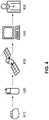
- FIG. 1a single-chamber ICD system shown. Its housing 110 together with the components therein is connected to a flexible, implantable electrode line 120. This has at its distal end a bipolar sensing and Stimulationspol, consisting of a right ventricular tip electrode 130 and a right ventricular ring electrode 140. For defibrillation shock delivery, a distal shock coil 150 and optionally a proximal shock coil 160 are attached to electrode lead 120 as the respective defibrillation or shock electrode.
- a bipolar sensing and Stimulationspolconsisting of a right ventricular tip electrode 130 and a right ventricular ring electrode 140.
- a distal shock coil 150 and optionally a proximal shock coil 160are attached to electrode lead 120 as the respective defibrillation or shock electrode.
- the electrocardiograms required for the determination according to the invention of the P-wave dispersioncan in principle be derived from the following electrode combinations: Option A: right ventricular tip electrode - ICD housing Variant B: right ventricular ring electrode - ICD housing Variant C: distal shock coil - ICD housing Variant D: Proximal shock coil - ICD housing
- the preferred derivativesare variant D, if a proximal shock coil is present, and variant C, if no proximal shock coil is present, since in these derivatives the imaging of the atrial excitation (P-wave) is most favorable.
- a selection matrixis provided in the exemplary embodiment, either manually programmable by the user, or automatically selecting the most favorable derivative for the P-wave determination on the basis of electrode impedances and signal quality.
- an atrial pacemaker electrodeeither tip electrode or ring electrode
- a floating atrial electrodewhich additionally housed as a ring electrode on the lead of the ventricular electrode is (A + or VDD principle).
- Upper curve 210shows an input signal with an amplitude of 0.1mV to simulate a very small P-wave.
- the input signalis somewhat noisy to simulate the real conditions of far-field electrocardiogram derivation.
- the second curve 220shows the derivative of these P-waves in the far-field electrocardiogram derived with an ICD between the proximal shock coil and the housing of the ICD.
- the interference signals shown next to the P-wave to be detectedstill do not permit automatic P-wave detection by the ICD.
- the third curve 230depicts the signal after it has been averaged over 24 cardiac cycles.
- the signal averagingis synchronized to a respective detected atrial heart action (atrial sense event).
- the atrial cardiac actionis detected in this embodiment in an electrocardiogram which has been recorded via the proximal shock electrode 160 and the housing of the implant 110.
- a separate right atrial electrodemay be used for atrial sensing.
- the signal quality after 24 averages(signal 230) is already sufficient to realize an automatic detection of the P-wave including its components (right-left atrium) in the ICD.
- the duration (t)also called width
- the duration of the averaged P-wavecorresponds to the 12-channel surface electrocardiogram with a sufficiently selected derivative vector and number of averaged cycles of the P-wave dispersion.
- a further improvement of the diagnostic statement - in particular for unmasking multiple foci of the atrial excitation -represents a count of discontinuities (S1..S4) in the averaged P-wave 230.
- FIG. 3For example, some components of an ICD designed for P-wave dispersion analysis described in the present invention are shown in block diagram form.
- the ICDis additionally connected here to a right-atrial sensing and stimulation electrode 310.
- the intracardiac electrocardiogram (inferred) taken with this electrodeis analyzed in a conventional ICD sensing stage 320 and the detected atrial cardiac events (atrial events, P-sense) subsequently become an ICD timer 330 for therapy control and rhythm diagnostics 340.
- the shock electrodes 391 and 392 connected to a shock generator 390 of the ICD and the electrically conductive housing 300 of the ICDare additionally connected to a far field electrocardiogram selection matrix 350.
- This selection matrix 350determines which of the electrodes will be used to derive (capture) a far-field electrocardiogram for P-wave dispersion analysis. The selection is made either manually by programming by the doctor or automatically by a signal quality analysis performed in the ICD (380: "Signal Quality Check").
- This far-field electrocardiogramis then preprocessed (amplified, digitized, filtered) in an electrocardiogram signal processing unit 360 and then delivered to an averager 370 as an averaging unit.
- the far-field electrocardiogram selection matrix 350 and the electrocardiogram signal processing unit 360together form a far-field electrocardiogram detection unit.
- the averaging device 370 connected theretoperforms a signal averaging triggered on a respectively detected atrial heart action (atrial event 320) and displays this averaged P- Waveforms are available to a morphology classifier 380.
- This morphology classifier 380measures the average P-wave in terms of its signal duration (signal width), possibly with regard to the number of discontinuities and optionally further morphological characteristics. This information is then provided to a diagnostic memory 340, maintaining a mapping to the atrial rhythm (330-> 340).
- the information on the P-wave dispersion and the atrial rhythm available in the diagnostic memory 340can be transmitted and displayed to the physician via a near field or far field telemetry 321.
- FIG. 4is an expanded overall system for continuous monitoring of the P-wave dispersion shown.
- the electronic implant 410 described aboveis connected to a relay station or base station 420 via RF telemetry (preferably in the MICS band) and periodically transmits the information regarding the freedom from atrial fibrillation to this relay station 420.
- This relaytransmits this information via the data transmission network 430 a remote monitoring server 440 to the doctor z.
- B.has access via the Internet and thus has the opportunity to telemedicine care the patient (eg, drug monitoring, ordering for ablation therapy).
- the implantcan immediately send a message to the remote monitoring system and the remote monitoring server then sends a special message to the attending physician (eg. as SMS, fax, e-mail or a particularly conspicuous marking of patients in the remote database).
- a special messageeg. as SMS, fax, e-mail or a particularly conspicuous marking of patients in the remote database.
- a stored IEGMis always sent to the remote monitoring server for events classified as non-atrial fibrillation free periods.
- FIG. 5is a multi-channel determination of the P-wave width ("dispersion") shown in an example.
- a first far-field electrocardiogram lead 510)is recorded and averaged and simultaneously a second far-field electrocardiogram lead 530 is recorded and averaged. Both far-field electrocardiogram leads are selected so that the atrial electrocardiogram can be well imaged.
- the right ventricular (alternatively left ventricular) derived intracardiac electrocardiogramis also recorded.
- the determination of the p-wave durationis carried out in such a way that 540 atrial excitation is searched for in the two atrial averages after the earliest onset. Subsequently, the end of 550 atrial pacing is determined in the two atrial mean electrocardiograms.
- the analysis window for the atrial excitationsis also limited to the rear.
- the information from the ventricular IEGMis used.
- the atrial analysis windowis limited at the earliest detectable ventricular pace 560.
- FIG. 6is a multichannel detector for determining the p-wave width after in FIG. 5 illustrated method illustrated.
- This detectoris connected to a right ventricular lead (600: RV), electrodes for a first far-field lead (630: FF1), and electrodes for a second far-field lead (660: FF2).
- the electrodes for the first far-field derivativecan, for. B. the proximal shock coil of an ICD electrode and the ICD housing.
- the electrodes for the second far-field derivativecan, for. B. the proximal ring of a coronary sinus electrode and the ICD housing.
- the right ventricular lead terminalis connected to a conventional IEGM signal processing sensing stage 610. This in turn passes the processed IEGM signals to an R-wave detector, which is so pronounced that it detects at least the earliest beginning of the R-wave and passes it on to the connected P-wave width detector 690.
- the two far-field terminals 630 and 660are connected to an electrocardiogram signal processing unit 640 and 670, respectively.
- These electrocardiogram signal processing units 640 and 670are designed such that they maximally amplify and broadband the atrial signals to be detected, so that the entire atrial excitation can be detected.
- Other parametersmay be set for the electrocardiogram signal processing of the first far-field channel 640, as for the electrocardiogram signal processing unit of the second far-field channel 670.
- the electrocardiogram signal processing unitsmay include algorithms that provide automatic beat-to-beat matching performs the parameter to capture optimally recorded electrocardiogram signals.
- the far-field electrocardiogram signal processing unitsare each associated with a P-wave averaging unit 650 and 680. These units average the arterial electrocardiogram over a defined number of cardiac cycles, either preset or automatically determined by a signal quality check (eg, based on signal-to-noise ratio evaluation).
- the results of the P-wave averaging (650, 680)are also fed to the P-wave width detector (690). This P-wave width detector then determines according to the description of FIG. 5 the duration of the P-wave.
Landscapes
- Health & Medical Sciences (AREA)
- Life Sciences & Earth Sciences (AREA)
- Cardiology (AREA)
- Heart & Thoracic Surgery (AREA)
- Molecular Biology (AREA)
- Pathology (AREA)
- Engineering & Computer Science (AREA)
- Biomedical Technology (AREA)
- Physics & Mathematics (AREA)
- Medical Informatics (AREA)
- Biophysics (AREA)
- Surgery (AREA)
- Animal Behavior & Ethology (AREA)
- General Health & Medical Sciences (AREA)
- Public Health (AREA)
- Veterinary Medicine (AREA)
- Measurement And Recording Of Electrical Phenomena And Electrical Characteristics Of The Living Body (AREA)
Description
Translated fromGermanDie Erfindung betrifft ein elektromedizinisches Implantat, das zum Bestimmen einer P-Wellendispersion ausgebildet ist. Das elektromedizinische Implantat kann beispielsweise ein entsprechend konfigurierter implantierbarer Herzschrittmacher oder ein implantierbarer Kardioverter/Defibrillator (ICD) oder eine Kombination aus Beidem sein.The invention relates to an electromedical implant, which is designed to determine a P-wave dispersion. The electromedical implant may be, for example, a suitably configured implantable pacemaker or an implantable cardioverter defibrillator (ICD) or a combination of both.
Wie derartige bekannte Geräte auch besitzt das elektromedizinische Implantat eine Aufnahmeeinheit zum Aufnehmen eines Elektrokardiogrammsignals. Diese Aufnahmeeinheit ist wenigstens mit zwei Elektroden zur Aufnahme elektrischer Signale verbunden oder zu verbinden, die den Verlauf eines Elektrokardiogrammsignals des rechten und des linken Vorhofes widerspiegeln.Like such known devices, the electro-medical implant has a receiving unit for receiving an electrocardiogram signal. This receiving unit is connected or connected to at least two electrodes for receiving electrical signals that reflect the course of an electrocardiogram signal of the right and left atrium.
Außerdem besitzt das elektromedizinische Implantat eine Detektionseinheit, die ausgebildet ist, für atriale Herzaktionen kennzeichnende Signalmerkmale in einem Elektrokardiogrammsignal zu detektieren. Letzteres geschieht bei bekannten implantierbaren Herzschrittmachern oder ICD dadurch, dass ein im Atrium eines Herzens aufgenommenes intraatriales Elektrokardiogrammsignal permanent einem Schwellwertvergleich unterzogen wird. Überschreitet die Amplitude des intraatrialen Elektrokardiogrammsignals den Schwellwert, wird eine atriale Herzaktion detektiert. Typischerweise ist hierfür eine atriale Sensing-Einheit vorgesehen. Die Detektion einer atrialen Herzaktion wird auch als atriales Sense-Ereignis bezeichnet. Das jeweils detektierte elektrische Signal ist Folge einer mit der Kontraktion des atrialen Myokards einhergehenden Dipolarisierung der atrialen Muskelzellen.In addition, the electromedical implant has a detection unit which is designed to detect signal characteristics indicative of atrial cardiac actions in an electrocardiogram signal. The latter happens in known implantable cardiac pacemakers or ICD in that a intraatrial electrocardiogram signal recorded in the atrium of a heart is permanently subjected to a threshold value comparison. If the amplitude of the intra-atrial electrocardiogram signal exceeds the threshold value, an atrial heart action is detected. Typically, an atrial sensing unit is provided for this purpose. The detection of an atrial heart action is also referred to as an atrial sense event. The respectively detected electrical signal is the result of a dipolarization of the atrial muscle cells that accompanies the contraction of the atrial myocardium.
Die Erfassung und Auswertung der atrialen Dispersion ist ebenfalls grundsätzlich bekannt. Die P-Wellen-Dispersion beschreibt die zeitliche Verteilung der P-Welle in den 12-Ableitungen des Oberflächen-Elektrokardiogramm und ist somit Ausdruck der atrialen Erregungsausbreitung. Vergrößert sich der Wert der P-Wellendispersion ist von einer inhomogenen atrialen Erregungsbildung und -leitung auszugehen. Insbesondere die durch mehrere Fokusse initiierte atriale Erregung im Vorfeld einer atrialen Arrhythmie verursacht eine inhomogene Erregung des Vorhofs und somit eine größere P-Wellen-Dispersion.The detection and evaluation of the atrial dispersion is also known in principle. The P-wave dispersion describes the time distribution of the P-wave in the 12-derivatives of the surface electrocardiogram and is thus an expression of the atrial spread of excitation. If the value of the p-wave dispersion increases, inhomogeneous atrial excitation formation and conduction must be assumed. In particular, the atrial excitation initiated by multiple focuses prior to an atrial arrhythmia causes an inhomogeneous atrial excitation and thus a larger P-wave dispersion.
Die P-Wellen-Dispersion stellt also eine wichtige diagnostische Information für Patienten mit einem Risiko für Vorhofarrhythmien dar. Da die Koinzidenz von Vorhofflimmern und die Indikation für einen ICD sehr hoch ist, hat dieser Parameter für diese Patienten eine große Bedeutung.Thus, P-wave dispersion is an important diagnostic information for patients at risk for atrial arrhythmias. Since the coincidence of atrial fibrillation and the indication for ICD is very high, this parameter is of great importance to these patients.
In
Die in der Literatur beschriebene P-Wellendispersion ist jedoch definiert im 12-Kanal-Oberflächen-Elektrokardiogramm als eine zeitliche "Zerstreuung" einer P-Welle gemessen in den 12-Ableitungen des Oberflächen-Elektrokardiogramm. Diese P-Wellendispersion ist damit Ausdruck der atrialen Erregungsbildung und -ausbreitung. Genau dies soll mit der beschriebenen Erfindung in einem elektronischen Implantat realisiert werden, ohne dass dazu eine atriale Elektrode zwingend erforderlich ist.However, the P-wave dispersion described in the literature is defined in the 12-channel surface electrocardiogram as a temporal "scattering" of a P-wave measured in the 12-lead surface electrocardiogram. This p-wave dispersion is thus an expression of the atrial excitation formation and propagation. Exactly this is to be realized with the described invention in an electronic implant, without the need for an atrial electrode is absolutely necessary.
Die Studie "
Bislang ist es nicht möglich, diesen Parameter in einem ICD automatisch zu erfassen.So far, it is not possible to automatically capture this parameter in an ICD.
Die Aufgabe der Erfindung besteht darin, einen der P-Wellen-Dispersion des 12-Kanal-Oberflächen-Elektrokardiogramms entsprechenden Parameter in einem implantierbaren Gerät (z. B. ICD, Herzschrittmacher, Rhythmusmonitor) zu erfassen und damit einen prediktiven diagnostischen Wert für das Management vom Vorhofflimmerpatienten bereitzustellen.The object of the invention is to detect a parameter corresponding to the P-wave dispersion of the 12-channel surface electrocardiogram in an implantable device (eg ICD, cardiac pacemaker, rhythm monitor) and thus a predictive diagnostic value for the management from the atrial fibrillation patient.
Wichtig ist dabei die exakte Bestimmung des frühesten Beginns der atrialen Erregung und des Endes der atrialen Erregung.What is important is the exact determination of the earliest onset of atrial pacing and the end of atrial pacing.
Erfindungsgemäß wird diese Aufgabe durch ein elektromedizinisches Implantat gelöst, das eine Fernfeld-Elektrokardiogrammerfassungseinheit zum Aufnehmen eines Fernfeld-Elektrokardiogrammsignals aufweist, die mit wenigstens zwei Elektroden zur Aufnahme solcher elektrischer Signale verbunden oder zu verbinden ist, die den Verlauf eines zur Aufnahme solcher elektrischer Signale verbunden oder zu verbinden ist, die den Verlauf eines Fernfeld-Elektrokardiogramms des rechten und des linken Vorhofs widerspiegeln. Außerdem weist das erfindungsgemäße elektromedizinische Implantat eine Detektionseinheit auf, die ausgebildet ist, für atriale Herzaktionen kennzeichnende Signalmerkmale in einem Elektrokardiogrammsignal zu detektieren. Weiterhin weist das elektromedizinische Implantat eine Mittelungseinheit auf, die mit der Aufnahmeeinheit und der Detektionseinheit verbunden und ausgebildet ist, ein gemitteltes P-Wellen-Signal zu generieren, in dem die Mittelungseinheit eine Mehrzahl von einer jeweiligen detektierten atrialen Herzaktion zugeordneten Signalabschnitten des Fernfeld-Elektrokardiogrammsignals miteinander mittelt. Schließlich besitzt das elektromedizinische Implantat eine Auswerteeinheit, die mit der Mittelungseinheit verbunden ist und ausgebildet ist, in dem jeweiligen gemittelten P-Wellen-Signal die Dauer einer gemittelten P-Welle zu bestimmen.According to the invention, this object is achieved by an electromedical implant having a far-field electrocardiogram detection unit for receiving a far-field electrocardiogram signal which is connected or connectable to at least two electrodes for receiving such electrical signals which connect the course of one for receiving such electrical signals to connect, which reflect the course of a far-field electrocardiogram of the right and left atrium. In addition, the electromedical implant according to the invention has a detection unit which is designed to detect signal characteristics characterizing atrial cardiac actions in an electrocardiogram signal. Furthermore, the electromedical implant has an averaging unit which is connected to the acquisition unit and the detection unit and configured to generate an averaged P-wave signal in which the averaging unit has a plurality of signal portions of the far-field electrocardiogram signal associated with a respective detected atrial cardiac action averages. Finally, the electro-medical implant has an evaluation unit, which is connected to the averaging unit and is designed to determine the duration of an averaged P-wave in the respective averaged P-wave signal.
Die Dauer einer jeweiligen gemittelten P-Welle spiegelt dabei die Dispersion der P-Welle wider.The duration of each averaged P-wave reflects the dispersion of the P-wave.
Die Erfindung beruht auf der Erkenntnis, dass ein mittels eines Implantats aufgenommenes Fernfeld-Elektrokardiogrammsignal, welches die Aktivität beider Vorhöfe widerspiegelt, besonders dafür geeignet ist, hinsichtlich einer P-Wellen-Dispersion analysiert zu werden.The invention is based on the finding that a far-field electrocardiogram signal recorded by means of an implant, which reflects the activity of both atria, is particularly suitable for being analyzed with regard to a P-wave dispersion.
Bei aus dem Stand der Technik bekannten Implantaten beruht die Analyse von P-Wellen typischerweise auf einem intraatrialen Elektrokardiogramm, welches mit einer relativ kleinflächigen Elektrode in einem Atrium eines Herzens aufgenommen wird. Derartige Elektrokardiogramme spiegeln regelmäßig im Wesentlichen die Aktivität eines einzigen Vorhofs, aber nicht beider Vorhöfe (Atrien) wider.In implants known in the art, analysis of P-waves is typically based on an intra-atrial electrocardiogram acquired with a relatively small area electrode in an atrium of a heart. Such electrocardiograms regularly reflect essentially the activity of a single atrium but not both atria.
Der Vorteil der erfindungsgemäßen Lösung besteht darin, dass nunmehr die diagnostische Information der P-Wellen-Dispersion in einem elektronischen Implantat, wie z. B. einem Herzschrittmacher, ICD oder implantierbaren Monitor erfasst werden kann. Dabei können die für die üblichen Anwendungen eines solchen Gerätes bereits vorhandenen Elektroden eingesetzt werden.The advantage of the solution according to the invention is that now the diagnostic information of the P-wave dispersion in an electronic implant, such. As a pacemaker, ICD or implantable monitor can be detected. In this case, the existing for the usual applications of such a device electrodes can be used.
Mit dieser diagnostische Information kann das Management von Vorhofflimmerpatienten erheblich verbessert werden, da nun ein kontinuierliches Monitoring der P-Wellendispersion möglich ist und so z. B. der Zeitpunkt einer Medikationsumstellung oder einer Vorhofflimmerablation vorausschauend geplant werden kann.With this diagnostic information, the management of atrial fibrillation patients can be significantly improved, since now a continuous monitoring of the P-wave dispersion is possible and so z. B. the time of a medication conversion or atrial fibrillation can be planned in advance.
Diese zusätzliche atriale Diagnostik kann auch zu einem differenzierterem Einsatz der Vorhofflimmerablation beitragen und somit die z. Z. noch zu hohen Kosten der Ablation zu senken.This additional atrial diagnosis can also contribute to a more sophisticated use of atrial fibrillation and thus the z. Z. To lower even high costs of ablation.
Im Folgenden werden nun einige vorteilhafte Ausgestaltungen näher erläutert.In the following, some advantageous embodiments will now be explained in more detail.
Die Detektionseinheit zum Erfassen atrialer Herzaktionen kann eine übliche atriale Sensingeinheit sein, die mit einer üblichen atrialen Elektrode verbunden sein kann. Vorzugsweise ist jedoch die Detektionseinheit mit der Fernfeld-Elektrokardiogrammerfassungs-einheit verbunden und ausgebildet, atriale Herzaktionen, beispielsweise anhand von Morphologiekriterien oder anderen Kriterien, in dem von der Fernfeld-Elektrokardiogrammerfassungseinheit aufgenommenen Fernfeld-Elektrokardiogramm zu detektieren. Die letztgenannte Variante hat den Vorteil, dass sie eine Erfassung und Analyse der P-Wellen-Dispersion auch mit solchen Implantaten ermöglicht, die keine eigene atriale Elektrode aufweisen, also beispielsweise bei Einkammer-Herzschrittmachern oder Einkammer-ICDs.The atrial cardiac action detecting unit may be a common atrial sensing unit that may be connected to a conventional atrial electrode. Preferably, however, the detection unit is connected to the far field electrocardiogram detection unit and configured to perform atrial cardiac actions, for example based on morphology criteria or other criteria, in the far field electrocardiogram detection unit detected far-field electrocardiogram. The last-mentioned variant has the advantage that it makes it possible to detect and analyze the P-wave dispersion even with implants which do not have their own atrial electrode, for example in the case of single-chamber cardiac pacemakers or single-chamber ICDs.
Das der Detektionseinheit zugeführte Elektrokardiogramm ist vorzugsweise gefiltert. Hierzu weist das Implantat vorzugsweise insbesondere einen Bandpassfilter auf, der auf den Frequenzbereich der zu detektierenden Signale abgestimmt ist.The electrocardiogram supplied to the detection unit is preferably filtered. For this purpose, the implant preferably has in particular a bandpass filter which is tuned to the frequency range of the signals to be detected.
Zur Aufnahme eines Fernfeld-Elektrokardiogrammsignals ist die Fernfeld-Elektrokardiogrammerfassungseinheit vorzugsweise wenigstens mit einem elektrisch leitenden Teil eines Gehäuses des Implantats mittels einer ersten Elektrode verbunden. Dies erlaubt zum einen die Aufnahme eines Fernfeld-Elektrokardiogramms, da sich das Gehäuse des Implantats außerhalb des Herzens in einem geeigneten Abstand befindet. Außerdem macht es diese Variante überflüssig, eine gesonderte Elektrode zu implantieren.To record a far-field electrocardiogram signal, the far-field electrocardiogram detection unit is preferably connected to at least one electrically conductive part of a housing of the implant by means of a first electrode. This allows for a recording of a far-field electrocardiogram, since the housing of the implant outside the heart is at a suitable distance. In addition, it makes this variant unnecessary to implant a separate electrode.
Weiterhin ist es bevorzugt, wenn die Fernfeld-Elektrokardiogrammerfassungseinheit mit einer Defibrillationselektrode an einer entsprechenden, mit dem Implantat verbundenen Elektrodenleitung als zweite Elektrode verbunden ist. Defibrillationselektroden sind in der Regel als Schockwendeln ausgebildet und im Vergleich zu typischen Stimulations- oder Sensingelektroden relativ großflächig. Eine besonders geeignete Elektrode ist eine atriale Schockwendel. Durch eine großflächige Elektrode als zweite Elektrode zur Aufnahme eines Fernfeld-Elektrokardiogramms wird bewirkt, dass das aufgenommene Elektrokardiogramm tatsächlich ein Fernfeld-Elektrokardiogramm ist.Furthermore, it is preferred if the far field electrocardiogram detection unit is connected to a defibrillation electrode on a corresponding electrode lead connected to the implant as a second electrode. Defibrillation electrodes are usually designed as shock coils and relatively large compared to typical stimulation or sensing electrodes. A particularly suitable electrode is an atrial shock coil. A large area electrode as a second electrode for receiving a far-field electrocardiogram causes the recorded electrocardiogram to actually be a far-field electrocardiogram.
Vorzugsweise ist das Implantat ist ein ICD, verbunden mit den üblichen Elektroden.Preferably, the implant is an ICD connected to the usual electrodes.
Speziell in diesem Fall (aber auch bei anderen Implantaten) kann die Fernfeld-Elektrokardiogrammerfassungseinheit auch mit an sich bekannten atrialen oder ventrikulären Ring- oder Tipelektroden verbunden sein, beispielsweise sind folgende Konfigurationen möglich:
Die breitbandige Ableitung des Fernfeld-Elektrokardiogramms zur Bestimmung der P-Wellendispersion erfolgt zwischen einer distalen Schockelektrode und dem Gehäuse eines ICD.Especially in this case (but also with other implants), the far-field electrocardiogram detection unit can also be connected to known atrial or ventricular ring or tip electrodes, for example the following configurations are possible:
The broadband derivative of the far-field electrocardiogram for determining P-wave dispersion occurs between a distal shock electrode and the housing of an ICD.
Die breitbandige Ableitung des Fernfeld-Elektrokardiogramms zur Bestimmung der P-Wellendispersion erfolgt zwischen einer proximalen Schockelektrode und dem Gehäuse eines ICD.The broadband derivative of the far-field electrocardiogram for determining P-wave dispersion occurs between a proximal shock electrode and the housing of an ICD.
Die breitbandige Ableitung des Fernfeld-Elektrokardiogramms zur Bestimmung der P-Wellendispersion erfolgt zwischen rechtsventrikulären Ringelektrode und dem Gehäuse eines ICD oder Herzschrittmachers.The broadband derivation of the far-field electrocardiogram for determining the P-wave dispersion takes place between the right-ventricular ring electrode and the housing of an ICD or cardiac pacemaker.
Die breitbandige Ableitung des Fernfeld-Elektrokardiogramms zur Bestimmung der P-Wellendispersion erfolgt zwischen einer rechtsventrikulären Tipelektrode und dem Gehäuse eines ICD oder Herzschrittmachers.The broadband derivation of the far-field electrocardiogram to determine the P-wave dispersion is performed between a right ventricular tip electrode and the housing of an ICD or cardiac pacemaker.
Vorteilhaft ist es auch, wenn die für die breitbandige Ableitung des Fernfeld-Elektrokardiogramms zur Bestimmung der P-Wellendispersion genutzten Elektrodenkonfigurationen manuell umgeschaltet oder umprogrammiert werden können.It is also advantageous if the electrode configurations used for the broadband derivation of the far-field electrocardiogram for determining the P-wave dispersion can be manually switched or reprogrammed.
Alternativ kann auch vorgesehen sein, dass die jeweilige für die breitbandige Ableitung des Fernfeld-Elektrokardiogramms zur Bestimmung der P-Wellendispersion genutzte E-lektrodenkonfiguration basierend auf einer Elektrokardiogramm-Signalqualitätsprüfung automatisch ausgewählt wird.Alternatively, it can also be provided that the respective electrode configuration used for the broadband derivation of the far-field electrocardiogram for determining the P-wave dispersion is selected automatically on the basis of an electrocardiogram signal quality test.
Die Auswerteeinheit besitzt vorzugsweise sowohl eine Einheit zum Bestimmen eines Anfangszeitpunkts einer gemittelten P-Welle als auch eine Einheit zum Bestimmen eines Endzeitpunkts einer gemittelten P-Welle. Diese beiden Einheiten können auch separat von der Auswerteeinheit vorgesehen sein und mit dieser verbunden sein. Die Auswerteeinheit ist dazu ausgebildet, die Dauer einer gemittelten P-Welle als Zeitdifferenz zwischen dem von der einen Einheit ermittelten Anfangszeitpunkt und dem von der anderen Einheit ermittelten Endzeitpunkt zu bestimmen. Diese beiden Einheiten zum Bestimmen des Anfangszeitpunkts bzw. des Endzeitpunkts einer gemittelten P-Welle sind vorzugsweise so ausgebildet, dass für sie jeweils eigene Detektionsparameter, wie z. B. Signalverstärkungsfaktor, Schwellwerte, verwendete Signale etc., vorgegeben werden können. Zu den auszuwählenden Vorgaben kann es auch gehören, ein bestimmtes von mehreren Elektrokardiogrammsignalen hinsichtlich des jeweiligen Zeitpunkts auszuwerten.The evaluation unit preferably has both a unit for determining a start time of an averaged P-wave and a unit for determining an end time of an averaged P-wave. These two units can also be provided separately from the evaluation unit and connected to it. The evaluation unit is designed to determine the duration of an averaged P-wave as a time difference between the start time determined by the one unit and the end time determined by the other unit. These two units for determining the start time or the end time of an averaged P-wave are preferably formed so that their own detection parameters such. B. signal amplification factor, thresholds, signals used, etc., can be specified. It may also belong to the preselected specifications to evaluate a particular one of several electrocardiogram signals with regard to the respective time.
Besonders vorteilhaft ist es, wenn die Mittelungseinheit, die Auswerteeinheit oder die Einheit zum Bestimmen eines Endzeitpunkts einer gemittelten P-Welle dazu ausgebildet ist, von einer jeweiligen P-Welle oder einem zu mittelnden Signalabschnitt ein zeitgleiches ventrikuläres Elektrokardiogramm abzuziehen, d.h. die Amplitude eines synchronen ventrikulären Elektrokardiogramms von der jeweils entsprechenden Amplitude der P-Welle oder des zu mittelnden Signalabschnitts zu subtrahieren.It is particularly advantageous if the averaging unit, the evaluation unit or the unit for determining an end time of an averaged P-wave is adapted to subtract from a respective P-wave or a signal portion to be averaged a simultaneous ventricular electrocardiogram, i. to subtract the amplitude of a synchronous ventricular electrocardiogram from the respective corresponding amplitude of the P-wave or signal portion to be averaged.
Die Mittelungseinheit ist vorzugsweise dazu ausgebildet, miteinander zu mittelnde Signalabschnitte so miteinander zu mitteln, dass sie über die jeweiligen Zeitpunkte der Detektion einer atrialen Herzaktion miteinander synchronisiert sind. Der Zeitpunkt der Detektion einer jeweiligen atrialen Herzaktion ist somit für jeden der zu mittelnden Signalabschnitte der Bezugszeitpunkt für die Mittlung der Signalabschnitte miteinander.The averaging unit is preferably designed to average signal portions to be averaged with one another in such a way that they are synchronized with one another over the respective points in time of the detection of an atrial heart action. The time of detection of a respective atrial heart action is thus for each of the signal sections to be averaged the reference time for the averaging of the signal sections with each other.
In Bezug auf die Mittelungseinheit ist es außerdem vorzugsweise vorgesehen, dass die Anzahl aufeinander folgender zu mittelnder Signalabschnitte einstellbar ist.With regard to the averaging unit, it is also preferably provided that the number of successive signal sections to be averaged is adjustable.
Gemäß einer bevorzugten Ausführungsvariante weist das Implantat eine Monitoringeinheit auf, die einen der P-Wellen-Dispersion entsprechenden Parameter - also insbesondere die von der Auswerteeinheit ermittelte Dauer der gemittelten P-Wellen regelmäßig, und zwar vorzugsweise kontinuierlich oder mindestens einmal täglich, überwacht.According to a preferred embodiment variant, the implant has a monitoring unit which regularly monitors a parameter corresponding to the p-wave dispersion, ie in particular the duration of the averaged P-waves determined by the evaluation unit, preferably continuously or at least once a day.
Besonders vorteilhaft ist es, wenn die Fernfeldelektrokardiogrammerfassungseinheit dazu ausgebildet ist, wenigstens zwei Fernfeldelektrokardiogrammsignale parallel aufzunehmen, wie dies nachfolgend mit Bezug auf die
Gemäß einer weiteren vorteilhaften Ausführungsvariante erfolgt eine breitbandige Ableitung des Fernfeld-Elektrokardiogramms zur Bestimmung der P-Wellendispersion über eine rechtsatriale, flottierende Elektrode (VDD-Prinzip).According to a further advantageous embodiment, a broadband derivative of the far-field electrocardiogram for determining the P-wave dispersion via a right-atrial, floating electrode (VDD principle).
Die Erfindung soll nun anhand eines Ausführungsbeispiels mit Bezug auf die Figuren näher erläutert werden. Von den Figuren zeigt:
- Fig. 1:
- ein Einkammer-ICD-System als Beispiel für ein elektromedizinisches Implantat;
- Fig. 2:
- eine beispielhafte Darstellung einer P-Welle in einem Fernfeld-Elektrokardiogramm;
- Fig. 3:
- ein Blockschaltbild einiger Komponenten eines Implantats;
- Fig. 4:
- Ein Beispiel für ein Implantat in einem Fernübertragungssystem;
- Fig. 5:
- ein Beispiel für eine mehrkanalige P-Wellendauer-Bestimmung; und
- Fig. 6:
- einen Mehrkanaldetektor zur P-Wellendauer-Bestimmung
- Fig. 1:
- a single-chamber ICD system as an example of an electromedical implant;
- Fig. 2:
- an exemplary representation of a P-wave in a far-field electrocardiogram;
- 3:
- a block diagram of some components of an implant;
- 4:
- An example of an implant in a telemetry system;
- Fig. 5:
- an example of a multi-channel P-wave duration determination; and
- Fig. 6:
- a multi-channel detector for P-wave duration determination
Als mögliches Ausführungsbeispiel ist in der
Die für die erfindungsgemäße Bestimmung der P-Wellen-Disperion benötigten Elektrokardiogramme können prinzipiell von folgenden Elektrodenkombinationen abgeleitet werden:
Die bevorzugten Ableitungen sind jedoch Variante D, sofern eine proximale Schockwendel vorhanden ist und Variante C, wenn keine proximale Schockwendel vorhanden ist, da in diesen Ableitungen die Abbildung der Vorhoferregung (P-Welle) am günstigsten ist.However, the preferred derivatives are variant D, if a proximal shock coil is present, and variant C, if no proximal shock coil is present, since in these derivatives the imaging of the atrial excitation (P-wave) is most favorable.
Da mehrere Ableitungen für die Bestimmung der P-Welle möglich sind, ist in dem Ausführungsbeispiel eine Auswahlmatrix vorgesehen, die entweder manuell durch den Anwender programmierbar, oder aber automatisch anhand von Elektrodenimpedanzen und Signalqualität die jeweils günstigste Ableitung für die P-Wellenbestimmung auswählt.Since several derivatives are possible for the determination of the P-wave, a selection matrix is provided in the exemplary embodiment, either manually programmable by the user, or automatically selecting the most favorable derivative for the P-wave determination on the basis of electrode impedances and signal quality.
Bei der Ausführung als Herzschrittmacher entfallen die dargestellten Schockwendeln 150 und 160. An deren Stelle erfolgt die Elektrokardiogramm-Ableitung über eine atriale Schrittmacherelektrode (wahlweise Tipelektrode oder Ringelektrode) oder aber über eine flottierende atriale Elektrode, die zusätzlich als Ringelektrode auf der Zuleitung der ventrikulären Elektrode untergebracht ist (A+ bzw. VDD-Prinzip).In the place of the electrocardiogram derivative via an atrial pacemaker electrode (either tip electrode or ring electrode) or via a floating atrial electrode, which additionally housed as a ring electrode on the lead of the ventricular electrode is (A + or VDD principle).
In der
Die obere Kurve 210 zeigt ein Eingangssignal mit einer Amplitude von 0,1mV, um eine sehr kleine P-Welle zu simulieren. Zusätzlich ist das Eingangssignal etwas verrauscht, um so die realen Bedingungen der Fernfeld-Elektrokardiogramm-Ableitung zu simulieren.
In der zweiten Kurve 220 wird die Ableitung dieser P-Wellen im Fernfeld-Elektrokardiogramm, abgeleitet mit einem ICD zwischen der proximalen Schockwendel und dem Gehäuse des ICD dargestellt. Die neben der zu erkennenden P-Welle abgebildeten Störsignale lassen noch keine automatische P-Wellenerkennung durch den ICD zu.The
In der dritten Kurve 230 ist das Signal dargestellt nachdem es über 24 Herzzyklen gemittelt wurde. Die Signalmittelung wird dabei auf eine jeweilige detektierte atriale Herzaktion (atriales Senseereignis) hin synchronisiert. Die atriale Herzaktion wird in diesem Ausführungsbeispiel in einem Elektrokardiogramm detektiert, das über die proximale Schockelektrode 160 und das Gehäuse des Implantates 110 aufgenommen wurde. Alternativ kann eine separate rechtsatriale Elektrode für das atriale Sensing verwendet werden.The
Die Signalqualität nach 24 Mittelungen (Signal 230) ist bereits hinreichend, um eine automatische Erkennung der P-Welle einschließlich ihrer Komponenten (rechtes-linkes Atrium) im ICD realisieren zu können.The signal quality after 24 averages (signal 230) is already sufficient to realize an automatic detection of the P-wave including its components (right-left atrium) in the ICD.
Basierend auf dem hinreichend gemittelten Signal 230 ist es nun möglich, Parameter zu bestimmen, die mit der P-Wellen-Dispersion korrelieren. Der dabei wichtigste Parameter stellt die Dauer (t) (auch Breite genannt) der P-Welle dar, die im Implantat bestimmt und gespeichert wird. Die Dauer der gemittelten P-Welle entspricht bei hinreichend gewähltem Ableitungsvektor und Zahl der gemittelten Zyklen der P-Wellen-Dispersion aus dem 12-Kanal-Oberflächen-Elektrokardiogramm.Based on the adequately averaged
Eine weitere Verbesserung der diagnostischen Aussage - insbesondere zur Demaskierung mehrere Fokusse der atrialen Erregung - stellt eine Zählung der Unstetigkeitsstellen (S1..S4) in der gemittelten P-Welle 230 dar.A further improvement of the diagnostic statement - in particular for unmasking multiple foci of the atrial excitation - represents a count of discontinuities (S1..S4) in the averaged P-
In der
Der ICD ist hier zusätzlich mit einer rechtsatrialen Wahrnehmungs- und Stimulationselektrode 310 verbunden. Das mit Hilfe dieser Elektrode aufgenommene (abgeleitete) intrakardiale Elektrokardiogramm wird in einer konventionellen ICD-Sensingstufe 320 analysiert und die detektieren atrialen Herzaktionen (atrialen Ereignisse; P-Sense) werden anschließend einem ICD-Zeitgeber 330 für die Therapiesteuerung und zur Rhythmusdiagnostik 340 zur Verfügung gestellt.The ICD is additionally connected here to a right-atrial sensing and
Nicht dargestellt ist der ventrikuläre Wahrnehmungs- und Stimulationskanal, da dieser für die erfindungsgemäße Implementierung keine Änderung gegenüber dem Stand der Technik erfährt.Not shown is the ventricular sensing and stimulation channel, since this undergoes no change from the prior art for the implementation according to the invention.
Die mit einem Schockgenerator 390 des ICD verbundenen Schockelektroden 391 und 392 und das elektrisch leitfähige Gehäuse 300 des ICD sind zusätzlich mit einer Fernfeld-Elektrokardiogramm-Auswahlmatrix 350 verbunden. Diese Auswahlmatrix 350 legt fest, welche der Elektroden für die Ableitung (Aufnahme) eines Fernfeldelektrokardiogramms zur P-Wellen-Dispersionanalyse verwendet werden. Die Auswahl erfolgt dabei entweder manuell durch eine Programmierung durch den Arzt oder aber automatisch durch eine im ICD durchgeführte Signalqualitätsanalyse (380: "Signalqualitätsprüfung"). Dieses Fernfeld-Elektrokardiogramm wird anschließend in einer Elektrokardiogramm-Signalverarbeitungseinheit 360 vorverarbeitet (verstärkt, digitalisiert, gefiltert) und dann einem Mittelwertbildner 370 als Mittelungseinheit zugeführt. Die Fernfeld-Elektrokardio-gramm-Auswahlmatrix 350 und die Elektrokardiogramm-Signalverarbeitungseinheit 360 bilden zusammen eine Fernfeldelektrokardiogrammerfassungseinheit dar. Der mit dieser verbundene Mittelwertbildner 370 führt eine auf eine jeweils detektierte atriale Herzaktion (atriales Ereignis 320) hin getriggerte Signalmittelung durch und stellt diese gemittelten P-Wellenaufzeichnungen einem Morphologieklasifizierer 380 zur Verfügung. Dieser Morphologieklassifizierer 380 vermisst die gemittelte P-Welle hinsichtlich ihrer Signaldauer (Signalbreite), ggf. hinsichtlich der Anzahl ihrer Unstetigkeitsstellen und optional weiterer morphologischer Charakteristika. Diese Information wird dann einem Diagnostikspeicher 340 zur Verfügung gestellt, wobei eine Zuordnung zum atrialen Rhythmus (330->340) erhalten bleibt.The shock electrodes 391 and 392 connected to a
Die im Diagnostikspeicher 340 verfügbare Information zur P-Wellen-Dispersion und zum atrialen Rhythmus kann über eine Nah- oder Fernfeldtelemetrie 321 dem Arzt übermittelt und angezeigt werden.The information on the P-wave dispersion and the atrial rhythm available in the
In
Optional kann das Implantat beim erneuten Auftreten von Vorhofflimmern bzw. einer Periode, in der die Kriterien zum Nachweis der Vorhofflimmerfreiheit nicht erfüllt sind, sofort eine Nachricht an das Fernüberwachungssystem senden und der Fernüberwachungsserver versendet dann eine spezielle Nachricht an den betreuenden Arzt (z. B. als SMS, Fax, Email oder eine besonders auffällige Kennzeichnung der Patienten in der Fernnachsorgedatenbank).Optionally, upon recurrence of atrial fibrillation or a period in which the criteria for detecting atrial flutter resistance are not met, the implant can immediately send a message to the remote monitoring system and the remote monitoring server then sends a special message to the attending physician (eg. as SMS, fax, e-mail or a particularly conspicuous marking of patients in the remote database).
Zur korrekten Analyse des klassifizierten Rhythmus durch den Arzt wird zu den als nichtvorhofflimmerfreien Perioden klassifizierten Ereignissen immer auch ein gespeichertes IEGM mit an den Fernüberwachungsserver versendet.For correct analysis of the classified rhythm by the physician, a stored IEGM is always sent to the remote monitoring server for events classified as non-atrial fibrillation free periods.
In der
In der
Der rechtsventrikuläre Elektrodenanschluss ist mit einer herkömmlichen Sensingstufe 610 zur IEGM-Signalverarbeitung verbunden. Diese wiederum leitet die aufbereiteten IEGM-Signale an einen R-Wellendetektor weiter, der derart ausgeprägt ist, dass dieser mindestens den frühesten Beginn der R-Welle detektiert und an den daran angeschlossenen P-Wellenbreitendetektor 690 weitergibt.The right ventricular lead terminal is connected to a conventional IEGM signal
Die beiden Fernfeld-Anschlüsse 630 und 660 sind jeweils mit einer Elektrokardiogramm-Signalverarbeitungseinheit 640 und 670 verbunden. Diese Elektrokardiogramm-Signalverarbeitungseinheiten 640 und 670 sind derart ausgeprägt, dass diese die zu erfassenden atrialen Signale maximal verstärken und breitbandig filtern, sodass die gesamte atriale Erregung erfasst werden kann. Für die Elektrokardiogramm-Signalverarbeitung des ersten Fernfeld-Kanals 640 können dabei andere Parameter eingestellt werden, wie für die Elektrokardiogramm-Signalverarbeitungseinheit des zweiten Fernfeld-Kanals 670. Optional können die Elektrokardiogramm-Signalverarbeitungseinheiten Algorithmen beinhalten, die eine automatische Schlag-zu-Schlag-Anpassung der Parameter durchführt, um so optimal aufgezeichnete Elektrokardiogramm-Signale zu erfassen.The two far-
Die Fernfeld-Elektrokardiogramm-Signalverarbeitungseinheiten sind jeweils einer P-Wellenmittelungseinheit 650 und 680 zugeordnet. Diese Einheiten mitteln das artiale Elektrokardiogramm über eine definierte Anzahl von Herzzyklen, wobei diese Anzahl entweder fest voreingestellt wird oder aber durch eine Signalqualitätsprüfung automatisch bestimmt wird (z. B. basierend auf der Auswertung des Signal-Rauschverhältnisses). Die Ergebnisse der P-Wellenmittelung (650, 680) werden ebenfalls dem P-Wellenbreitendetektor (690) zugeführt. Dieser P-Wellenbreitendetektor bestimmt dann gemäß der Beschreibung von
Claims (10)
- An electromedical implant comprising- a far-field electrocardiogram capturing unit (350, 360) for recording a far-field electrocardiogram signal, which unit is connected or can be connected to at least two electrodes for recording electrical signals which reflect the course of a far-field electrocardiogram of the right and left atria,- with a detection unit (320), which is connected to the recording unit or is part thereof and is designed to detect signal features characterising atrial heart actions in a far-field electrocardiogram signal,- an averaging unit (370), which is connected to the recording unit and the detection unit and is designed to generate an averaged P-wave signal in that the averaging unit averages a plurality of signal portions of the electrocardiogram signal associated with a particular detected atrial heart action with one another, and- an evaluation unit (380), which is connected to the averaging unit (370) and is designed to determine the duration of an averaged P-wave in a particular averaged P-wave signal,- a monitoring unit, which is connected to the evaluation unit and which is designed to regularly monitor a parameter corresponding to the P-wave dispersion, specifically the duration of an averaged P-wave determined by the evaluation unit,characterised in that
the far-field electrocardiogram capturing unit is designed to record at least two far-field electrocardiogram signals in parallel and to average them in order to determine the P-wave duration. - The implant according to claim 1,characterised in that the detection unit is designed to detect signal features characterising atrial heart actions in a filtered electrocardiogram signal.
- The implant according to either one of claims 1 or 2,characterised in that the far-field electrocardiogram capturing unit is connected to an electrically conductive portion of a housing of the implant as a first of the at least two electrodes.
- The implant according to claim 3,characterised in that the far-field electrocardiogram capturing unit is connected to a defibrillation electrode suitable for intracardial positioning as a second of the at least two electrodes.
- The implant according to any one of claims 1 to 4,characterised in that the evaluation unit contains a unit for determining a start time of an averaged P-wave or is connected to such a unit and contains a unit for determining an end time of an averaged P-wave or is connected to such a unit and is designed to determine the duration of an averaged P-wave as a time difference between the start time and end time.
- The implant according to claim 5,characterised in that separate detection parameters can be specified for the unit for determining a start time of an averaged P-wave and for the unit for determining an end time of an averaged P-wave.
- The implant according to claim 5 or 6,characterised in that the averaging unit, the evaluation unit or the unit for determining an end time of an averaged P-wave is designed to deduct an isochronous ventricular electrocardiogram from a particular P-wave or a signal portion to be averaged.
- The implant according to any one of claims 1 to 7,characterised in that the averaging unit is designed to average with one another the signal portions that are to be averaged with one another such that they are synchronised with one another via the various times of the detection of an atrial heart action of each signal portion.
- The implant according to any one of claims 1 to 8,characterised in that the averaging unit is designed to average with one another an adjustable number of successive signal portions.
- The implant according to any one of claims 1 to 9,characterised in that the far-field electrocardiogram capturing unit is designed to record a broadband far-field electrocardiogram via a right-atrial, floating electrode.
Applications Claiming Priority (1)
| Application Number | Priority Date | Filing Date | Title |
|---|---|---|---|
| DE102009002988ADE102009002988A1 (en) | 2009-05-11 | 2009-05-11 | Implantable P-wave dispersion detector |
Publications (2)
| Publication Number | Publication Date |
|---|---|
| EP2250962A1 EP2250962A1 (en) | 2010-11-17 |
| EP2250962B1true EP2250962B1 (en) | 2019-07-31 |
Family
ID=42333333
Family Applications (1)
| Application Number | Title | Priority Date | Filing Date |
|---|---|---|---|
| EP10158185.8AActiveEP2250962B1 (en) | 2009-05-11 | 2010-03-29 | Implantable P-wave dispersion detector |
Country Status (3)
| Country | Link |
|---|---|
| US (1) | US8321001B2 (en) |
| EP (1) | EP2250962B1 (en) |
| DE (1) | DE102009002988A1 (en) |
Families Citing this family (1)
| Publication number | Priority date | Publication date | Assignee | Title |
|---|---|---|---|---|
| US11826149B2 (en) | 2020-11-02 | 2023-11-28 | Medtronic, Inc. | Electrocardiogram gain adjustment |
Family Cites Families (6)
| Publication number | Priority date | Publication date | Assignee | Title |
|---|---|---|---|---|
| US6292694B1 (en)* | 1999-06-22 | 2001-09-18 | Pacesetter, Inc. | Implantable medical device having atrial tachyarrhythmia prevention therapy |
| US6449503B1 (en)* | 1999-07-14 | 2002-09-10 | Cardiac Pacemakers, Inc. | Classification of supraventricular and ventricular cardiac rhythms using cross channel timing algorithm |
| US6904315B2 (en)* | 2000-12-14 | 2005-06-07 | Medtronic, Inc. | Atrial aware VVI: a method for atrial synchronous ventricular (VDD/R) pacing using the subcutaneous electrode array and a standard pacing lead |
| US7620446B2 (en) | 2003-07-31 | 2009-11-17 | Medtronic, Inc. | Monitoring P-waves to detect degradation of atrial myocardium |
| US7328063B2 (en)* | 2004-11-30 | 2008-02-05 | Cardiac Pacemakers, Inc. | Method and apparatus for arrhythmia classification using atrial signal mapping |
| US7460902B2 (en)* | 2005-02-02 | 2008-12-02 | The General Electric Company | Monitoring of atrial activation |
- 2009
- 2009-05-11DEDE102009002988Apatent/DE102009002988A1/ennot_activeWithdrawn
- 2010
- 2010-03-29EPEP10158185.8Apatent/EP2250962B1/enactiveActive
- 2010-04-16USUS12/762,116patent/US8321001B2/ennot_activeExpired - Fee Related
Non-Patent Citations (1)
| Title |
|---|
| None* |
Also Published As
| Publication number | Publication date |
|---|---|
| DE102009002988A1 (en) | 2010-11-25 |
| US20100286540A1 (en) | 2010-11-11 |
| US8321001B2 (en) | 2012-11-27 |
| EP2250962A1 (en) | 2010-11-17 |
Similar Documents
| Publication | Publication Date | Title |
|---|---|---|
| DE60315485T2 (en) | DEVICE FOR DETECTING THE R-WAVE OF THE HEART IN A BODY ECG WAVEFORM | |
| DE60210086T2 (en) | REAL TIME HIGH FREQUENCY QRS ELECTROCARDIOGRAPH | |
| DE60016276T2 (en) | CLASSIFICATION OF SIGNALS WITH A CRUEL CHANNEL TIMING ALGORITHM | |
| DE69330820T2 (en) | Device for analyzing the function of a heart | |
| DE60013786T2 (en) | CHECKING THE ACCURACY OF A NORMAL STANDARD PATTERN | |
| DE69330217T2 (en) | Implantable device for determining and controlling the effect of the sympathetic vagus nerve | |
| EP0617918B1 (en) | Apparatus for analysis of potential course signals of an electrocardiogram | |
| EP1510173B1 (en) | Intracardial impedance measuring device | |
| DE60025486T2 (en) | ADJUSTABLE EVOCATED HEART RESPONSE MEASURING DEVICE FOR AUTOMATIC EXAMINATION | |
| DE69114517T2 (en) | METHOD FOR DETECTING A PATHOLOGICAL STATE OF THE VENTILATION FOR AN AUTOMATIC DEFIBRILLATION. | |
| DE69533344T2 (en) | Synchronization system for cardioverting | |
| DE60020514T2 (en) | Method for distinguishing heart-recorded electrical events and corresponding system | |
| DE4304269A1 (en) | ||
| EP2123324B1 (en) | ECG Analyzing Device | |
| EP2181648B1 (en) | Single chamber heart simulator | |
| DE69732887T2 (en) | Stimulus pulse detector | |
| EP2250962B1 (en) | Implantable P-wave dispersion detector | |
| EP2140910B1 (en) | Heart stimulator for treating cardiac tachyarrhythmias | |
| EP2111893A1 (en) | Ventricular heart stimulator | |
| DE10048649A1 (en) | Risikomontoring | |
| DE10046241A1 (en) | Pacemaker system with improved classification of physiological events and improved heart monitoring, based on DSP | |
| DE102008043480A1 (en) | Single-chamber cardiac stimulator | |
| EP3679984A1 (en) | Implantable assembly for stimulating a human or animal heart | |
| WO2020182609A1 (en) | System for predicting at least one cardiological dysfunction in an individual | |
| DE112006001098B4 (en) | Implantable cardiac device |
Legal Events
| Date | Code | Title | Description |
|---|---|---|---|
| PUAI | Public reference made under article 153(3) epc to a published international application that has entered the european phase | Free format text:ORIGINAL CODE: 0009012 | |
| AK | Designated contracting states | Kind code of ref document:A1 Designated state(s):AT BE BG CH CY CZ DE DK EE ES FI FR GB GR HR HU IE IS IT LI LT LU LV MC MK MT NL NO PL PT RO SE SI SK SM TR | |
| 17P | Request for examination filed | Effective date:20110512 | |
| STAA | Information on the status of an ep patent application or granted ep patent | Free format text:STATUS: EXAMINATION IS IN PROGRESS | |
| 17Q | First examination report despatched | Effective date:20170418 | |
| RAP1 | Party data changed (applicant data changed or rights of an application transferred) | Owner name:BIOTRONIK SE & CO. KG | |
| GRAP | Despatch of communication of intention to grant a patent | Free format text:ORIGINAL CODE: EPIDOSNIGR1 | |
| STAA | Information on the status of an ep patent application or granted ep patent | Free format text:STATUS: GRANT OF PATENT IS INTENDED | |
| INTG | Intention to grant announced | Effective date:20190219 | |
| GRAS | Grant fee paid | Free format text:ORIGINAL CODE: EPIDOSNIGR3 | |
| GRAA | (expected) grant | Free format text:ORIGINAL CODE: 0009210 | |
| STAA | Information on the status of an ep patent application or granted ep patent | Free format text:STATUS: THE PATENT HAS BEEN GRANTED | |
| AK | Designated contracting states | Kind code of ref document:B1 Designated state(s):AT BE BG CH CY CZ DE DK EE ES FI FR GB GR HR HU IE IS IT LI LT LU LV MC MK MT NL NO PL PT RO SE SI SK SM TR | |
| REG | Reference to a national code | Ref country code:CH Ref legal event code:EP Ref country code:GB Ref legal event code:FG4D Free format text:NOT ENGLISH | |
| REG | Reference to a national code | Ref country code:DE Ref legal event code:R096 Ref document number:502010016154 Country of ref document:DE | |
| REG | Reference to a national code | Ref country code:AT Ref legal event code:REF Ref document number:1160061 Country of ref document:AT Kind code of ref document:T Effective date:20190815 | |
| REG | Reference to a national code | Ref country code:IE Ref legal event code:FG4D Free format text:LANGUAGE OF EP DOCUMENT: GERMAN | |
| REG | Reference to a national code | Ref country code:NL Ref legal event code:MP Effective date:20190731 | |
| REG | Reference to a national code | Ref country code:LT Ref legal event code:MG4D | |
| PG25 | Lapsed in a contracting state [announced via postgrant information from national office to epo] | Ref country code:SE Free format text:LAPSE BECAUSE OF FAILURE TO SUBMIT A TRANSLATION OF THE DESCRIPTION OR TO PAY THE FEE WITHIN THE PRESCRIBED TIME-LIMIT Effective date:20190731 Ref country code:LT Free format text:LAPSE BECAUSE OF FAILURE TO SUBMIT A TRANSLATION OF THE DESCRIPTION OR TO PAY THE FEE WITHIN THE PRESCRIBED TIME-LIMIT Effective date:20190731 Ref country code:HR Free format text:LAPSE BECAUSE OF FAILURE TO SUBMIT A TRANSLATION OF THE DESCRIPTION OR TO PAY THE FEE WITHIN THE PRESCRIBED TIME-LIMIT Effective date:20190731 Ref country code:FI Free format text:LAPSE BECAUSE OF FAILURE TO SUBMIT A TRANSLATION OF THE DESCRIPTION OR TO PAY THE FEE WITHIN THE PRESCRIBED TIME-LIMIT Effective date:20190731 Ref country code:NO Free format text:LAPSE BECAUSE OF FAILURE TO SUBMIT A TRANSLATION OF THE DESCRIPTION OR TO PAY THE FEE WITHIN THE PRESCRIBED TIME-LIMIT Effective date:20191031 Ref country code:BG Free format text:LAPSE BECAUSE OF FAILURE TO SUBMIT A TRANSLATION OF THE DESCRIPTION OR TO PAY THE FEE WITHIN THE PRESCRIBED TIME-LIMIT Effective date:20191031 Ref country code:NL Free format text:LAPSE BECAUSE OF FAILURE TO SUBMIT A TRANSLATION OF THE DESCRIPTION OR TO PAY THE FEE WITHIN THE PRESCRIBED TIME-LIMIT Effective date:20190731 Ref country code:PT Free format text:LAPSE BECAUSE OF FAILURE TO SUBMIT A TRANSLATION OF THE DESCRIPTION OR TO PAY THE FEE WITHIN THE PRESCRIBED TIME-LIMIT Effective date:20191202 | |
| PG25 | Lapsed in a contracting state [announced via postgrant information from national office to epo] | Ref country code:ES Free format text:LAPSE BECAUSE OF FAILURE TO SUBMIT A TRANSLATION OF THE DESCRIPTION OR TO PAY THE FEE WITHIN THE PRESCRIBED TIME-LIMIT Effective date:20190731 Ref country code:GR Free format text:LAPSE BECAUSE OF FAILURE TO SUBMIT A TRANSLATION OF THE DESCRIPTION OR TO PAY THE FEE WITHIN THE PRESCRIBED TIME-LIMIT Effective date:20191101 Ref country code:LV Free format text:LAPSE BECAUSE OF FAILURE TO SUBMIT A TRANSLATION OF THE DESCRIPTION OR TO PAY THE FEE WITHIN THE PRESCRIBED TIME-LIMIT Effective date:20190731 Ref country code:IS Free format text:LAPSE BECAUSE OF FAILURE TO SUBMIT A TRANSLATION OF THE DESCRIPTION OR TO PAY THE FEE WITHIN THE PRESCRIBED TIME-LIMIT Effective date:20191130 | |
| PG25 | Lapsed in a contracting state [announced via postgrant information from national office to epo] | Ref country code:TR Free format text:LAPSE BECAUSE OF FAILURE TO SUBMIT A TRANSLATION OF THE DESCRIPTION OR TO PAY THE FEE WITHIN THE PRESCRIBED TIME-LIMIT Effective date:20190731 | |
| PG25 | Lapsed in a contracting state [announced via postgrant information from national office to epo] | Ref country code:RO Free format text:LAPSE BECAUSE OF FAILURE TO SUBMIT A TRANSLATION OF THE DESCRIPTION OR TO PAY THE FEE WITHIN THE PRESCRIBED TIME-LIMIT Effective date:20190731 Ref country code:IT Free format text:LAPSE BECAUSE OF FAILURE TO SUBMIT A TRANSLATION OF THE DESCRIPTION OR TO PAY THE FEE WITHIN THE PRESCRIBED TIME-LIMIT Effective date:20190731 Ref country code:DK Free format text:LAPSE BECAUSE OF FAILURE TO SUBMIT A TRANSLATION OF THE DESCRIPTION OR TO PAY THE FEE WITHIN THE PRESCRIBED TIME-LIMIT Effective date:20190731 Ref country code:PL Free format text:LAPSE BECAUSE OF FAILURE TO SUBMIT A TRANSLATION OF THE DESCRIPTION OR TO PAY THE FEE WITHIN THE PRESCRIBED TIME-LIMIT Effective date:20190731 Ref country code:EE Free format text:LAPSE BECAUSE OF FAILURE TO SUBMIT A TRANSLATION OF THE DESCRIPTION OR TO PAY THE FEE WITHIN THE PRESCRIBED TIME-LIMIT Effective date:20190731 | |
| PG25 | Lapsed in a contracting state [announced via postgrant information from national office to epo] | Ref country code:CZ Free format text:LAPSE BECAUSE OF FAILURE TO SUBMIT A TRANSLATION OF THE DESCRIPTION OR TO PAY THE FEE WITHIN THE PRESCRIBED TIME-LIMIT Effective date:20190731 Ref country code:SM Free format text:LAPSE BECAUSE OF FAILURE TO SUBMIT A TRANSLATION OF THE DESCRIPTION OR TO PAY THE FEE WITHIN THE PRESCRIBED TIME-LIMIT Effective date:20190731 Ref country code:SK Free format text:LAPSE BECAUSE OF FAILURE TO SUBMIT A TRANSLATION OF THE DESCRIPTION OR TO PAY THE FEE WITHIN THE PRESCRIBED TIME-LIMIT Effective date:20190731 Ref country code:IS Free format text:LAPSE BECAUSE OF FAILURE TO SUBMIT A TRANSLATION OF THE DESCRIPTION OR TO PAY THE FEE WITHIN THE PRESCRIBED TIME-LIMIT Effective date:20200224 | |
| REG | Reference to a national code | Ref country code:DE Ref legal event code:R097 Ref document number:502010016154 Country of ref document:DE | |
| PLBE | No opposition filed within time limit | Free format text:ORIGINAL CODE: 0009261 | |
| STAA | Information on the status of an ep patent application or granted ep patent | Free format text:STATUS: NO OPPOSITION FILED WITHIN TIME LIMIT | |
| PG2D | Information on lapse in contracting state deleted | Ref country code:IS | |
| PG25 | Lapsed in a contracting state [announced via postgrant information from national office to epo] | Ref country code:IS Free format text:LAPSE BECAUSE OF FAILURE TO SUBMIT A TRANSLATION OF THE DESCRIPTION OR TO PAY THE FEE WITHIN THE PRESCRIBED TIME-LIMIT Effective date:20191030 | |
| 26N | No opposition filed | Effective date:20200603 | |
| PG25 | Lapsed in a contracting state [announced via postgrant information from national office to epo] | Ref country code:SI Free format text:LAPSE BECAUSE OF FAILURE TO SUBMIT A TRANSLATION OF THE DESCRIPTION OR TO PAY THE FEE WITHIN THE PRESCRIBED TIME-LIMIT Effective date:20190731 | |
| PG25 | Lapsed in a contracting state [announced via postgrant information from national office to epo] | Ref country code:MC Free format text:LAPSE BECAUSE OF FAILURE TO SUBMIT A TRANSLATION OF THE DESCRIPTION OR TO PAY THE FEE WITHIN THE PRESCRIBED TIME-LIMIT Effective date:20190731 | |
| REG | Reference to a national code | Ref country code:DE Ref legal event code:R079 Ref document number:502010016154 Country of ref document:DE Free format text:PREVIOUS MAIN CLASS: A61B0005045200 Ipc:A61B0005349000 | |
| REG | Reference to a national code | Ref country code:BE Ref legal event code:MM Effective date:20200331 | |
| PG25 | Lapsed in a contracting state [announced via postgrant information from national office to epo] | Ref country code:LU Free format text:LAPSE BECAUSE OF NON-PAYMENT OF DUE FEES Effective date:20200329 | |
| PG25 | Lapsed in a contracting state [announced via postgrant information from national office to epo] | Ref country code:FR Free format text:LAPSE BECAUSE OF NON-PAYMENT OF DUE FEES Effective date:20200331 | |
| PG25 | Lapsed in a contracting state [announced via postgrant information from national office to epo] | Ref country code:BE Free format text:LAPSE BECAUSE OF NON-PAYMENT OF DUE FEES Effective date:20200331 | |
| GBPC | Gb: european patent ceased through non-payment of renewal fee | Effective date:20200329 | |
| PG25 | Lapsed in a contracting state [announced via postgrant information from national office to epo] | Ref country code:GB Free format text:LAPSE BECAUSE OF NON-PAYMENT OF DUE FEES Effective date:20200329 | |
| REG | Reference to a national code | Ref country code:AT Ref legal event code:MM01 Ref document number:1160061 Country of ref document:AT Kind code of ref document:T Effective date:20200329 | |
| PG25 | Lapsed in a contracting state [announced via postgrant information from national office to epo] | Ref country code:AT Free format text:LAPSE BECAUSE OF NON-PAYMENT OF DUE FEES Effective date:20200329 | |
| PG25 | Lapsed in a contracting state [announced via postgrant information from national office to epo] | Ref country code:MT Free format text:LAPSE BECAUSE OF FAILURE TO SUBMIT A TRANSLATION OF THE DESCRIPTION OR TO PAY THE FEE WITHIN THE PRESCRIBED TIME-LIMIT Effective date:20190731 Ref country code:CY Free format text:LAPSE BECAUSE OF FAILURE TO SUBMIT A TRANSLATION OF THE DESCRIPTION OR TO PAY THE FEE WITHIN THE PRESCRIBED TIME-LIMIT Effective date:20190731 | |
| PG25 | Lapsed in a contracting state [announced via postgrant information from national office to epo] | Ref country code:MK Free format text:LAPSE BECAUSE OF FAILURE TO SUBMIT A TRANSLATION OF THE DESCRIPTION OR TO PAY THE FEE WITHIN THE PRESCRIBED TIME-LIMIT Effective date:20190731 | |
| PGFP | Annual fee paid to national office [announced via postgrant information from national office to epo] | Ref country code:IE Payment date:20230320 Year of fee payment:14 | |
| PGFP | Annual fee paid to national office [announced via postgrant information from national office to epo] | Ref country code:DE Payment date:20230320 Year of fee payment:14 | |
| P01 | Opt-out of the competence of the unified patent court (upc) registered | Effective date:20230605 | |
| PGFP | Annual fee paid to national office [announced via postgrant information from national office to epo] | Ref country code:CH Payment date:20230402 Year of fee payment:14 | |
| REG | Reference to a national code | Ref country code:DE Ref legal event code:R119 Ref document number:502010016154 Country of ref document:DE | |
| REG | Reference to a national code | Ref country code:CH Ref legal event code:PL | |
| PG25 | Lapsed in a contracting state [announced via postgrant information from national office to epo] | Ref country code:DE Free format text:LAPSE BECAUSE OF NON-PAYMENT OF DUE FEES Effective date:20241001 | |
| PG25 | Lapsed in a contracting state [announced via postgrant information from national office to epo] | Ref country code:IE Free format text:LAPSE BECAUSE OF NON-PAYMENT OF DUE FEES Effective date:20240329 | |
| PG25 | Lapsed in a contracting state [announced via postgrant information from national office to epo] | Ref country code:IE Free format text:LAPSE BECAUSE OF NON-PAYMENT OF DUE FEES Effective date:20240329 Ref country code:DE Free format text:LAPSE BECAUSE OF NON-PAYMENT OF DUE FEES Effective date:20241001 Ref country code:CH Free format text:LAPSE BECAUSE OF NON-PAYMENT OF DUE FEES Effective date:20240331 |